

Page 1
MAKING MODERN LIVING POSSIBLE
Quick Guide
VLT® HVAC Basic Drive FC 101
Page 2
Contents
1 Quick Guide
1-1
1.1 Safety
1-1
1.1.1 Warnings 1-1
1.1.2 Safety Instructions 1-1
1.2 Introduction
1-2
1.2.1 Available Literature 1-2
1.2.2 Approvals 1-2
1.2.3 IT Line Power 1-2
1.2.4 Avoid Unintended Start 1-3
1.2.5 Disposal Instruction 1-3
1.3 Installation
1-3
1.3.1 Before Starting Repair Work 1-3
1.3.2 Side-by-Side Installation 1-3
1.3.3 Dimensions 1-4
1.3.4 Electrical Installation in General 1-6
1.3.5 Connecting to Line Power and Motor 1-7
1.3.6 Fuses 1-14
1.3.7 EMC-compatible Electrical Installation 1-16
1.3.8 Control Terminals 1-18
1.3.9 Electrical Overview 1-19
1.4 Programming
1-20
1.4.1 Programming with the Local Control Panel (LCP) 1-20
1.4.3 The Start-up Wizard for Open-loop Applications 1-21
1.5.1 Main menu structure 1-32
1.6 Warnings and Alarms
1-34
1.7 General Specifications
1-36
1.7.1 Line Power Supply 3x200–240 V AC 1-37
1.7.2 Line Power Supply 3x380–480 V AC 1-38
1.7.3 Line Power Supply 3x380–480 V AC 1-40
1.7.4 Line Power Supply 3x525–600 V AC 1-42
1.8 Special Conditions
1-47
1.8.1 Derating for Ambient Temperature and Switching Frequency 1-47
1.8.2 Derating for Low Air Pressure 1-47
1.9 Options for VLT® HVAC Basic Drive FC 101
1-47
1.10 MCT 10 Support
1-47
Contents
VLT® HVAC Basic Drive Quick Guide
MG18A422 - VLT® is a registered Danfoss trademark
Page 3

Contents
VLT® HVAC Basic Drive Quick Guide
MG18A422 - VLT® is a registered Danfoss trademark
Page 4
1 Quick Guide
1.1 Safety
1.1.1 Warnings
WARNING
High Voltage Warning
The voltage of the adjustable frequency drive is dangerous
whenever it is connected to line power. Incorrect installation of the motor or adjustable frequency drive may
cause damage to the equipment, serious injury or death.
Consequently, it is essential to comply with the
instructions in this manual as well as local and national
rules and safety regulations.
WARNING
DISCHARGE TIME!
Adjustable frequency drives contain DC link capacitors that
can remain charged even when the adjustable frequency
drive is not powered. To avoid electrical hazards,
disconnect AC line power, any permanent magnet type
motors, and any remote DC link power supplies, including
battery backups, UPS and DC link connections to other
adjustable frequency drives. Wait for the capacitors to fully
discharge before performing any service or repair work.
The wait time required is listed in the Discharge Time table.
Failure to wait for the specified period of time after power
has been removed to do service or repair could result in
death or serious injury.
Voltage [V] Power range hp/[kW] Minimum waiting time
[min]
3x200 0.34–5 [0.25–3.7] 4
3x200 7.5–15 [5.5–11] 15
3x400 0.5–10 [0.37–7.5] 4
3x400 15–125 [11–90] 15
3x600 3–10 [2.2–7.5] 4
3x600 15–125 [11–90] 15
Table 1.1 Discharge Time
CAUTION
Leakage Current:
The ground leakage current from the adjustable frequency
drive exceeds 3.5 mA. According to IEC 61800-5-1 a
reinforced Protective Ground connection must be ensured
with a min. 10 mm² Cu or an additional PG wire - with the
same cable cross-section as the line power wiring - must
be terminated separately.
Residual Current Device:
This product can cause a DC current in the protective
conductor. Where a residual current device (RCD) is used
for extra protection, only an RCD of Type B (time delayed)
shall be used on the supply side of this product. See also
Danfoss Application Note on RCD, MN90G.
Protective grounding of the adjustable frequency drive and
the use of RCDs must always follow national and local
regulations.
Motor thermal protection:
Motor overload protection is possible by setting Parameter
1-90 Motor thermal protection to the value Electronic
Thermal Relay (ETR) trip.
WARNING
Installation at high altitudes
For altitudes above 6,600 feet [2 km], contact Danfoss
regarding PELV.
1.1.2 Safety Instructions
•
Make sure the adjustable frequency drive is
properly grounded.
•
Do not remove AC line input connections, motor
connections or other power connections while
the adjustable frequency drive is connected to
line power.
•
Protect users against supply voltage.
•
Protect the motor against overloading according
to national and local regulations.
•
The ground leakage current exceeds 3.5 mA.
•
The [Off/Reset] key is not a safety switch. It does
not disconnect the adjustable frequency drive
from line power.
Quick Guide
VLT® HVAC Basic Drive Quick Guide
MG18A422 - VLT® is a registered Danfoss trademark 1-1
1 1
Page 5
1.2 Introduction
1.2.1 Available Literature
This Quick Guide contains the basic information necessary
for installing and running the adjustable frequency drive. If
more information is needed, literature can be found on the
enclosed CD or downloaded from:
www.danfoss.com/BusinessAreas/DrivesSolutions/Documentations/Technical+Documentation.htm
1.2.2 Approvals
Table 1.2
IP54 enclosure adjustable
frequency drive do not have UL
approvals.
Table 1.3
1.2.3
IT Line Power
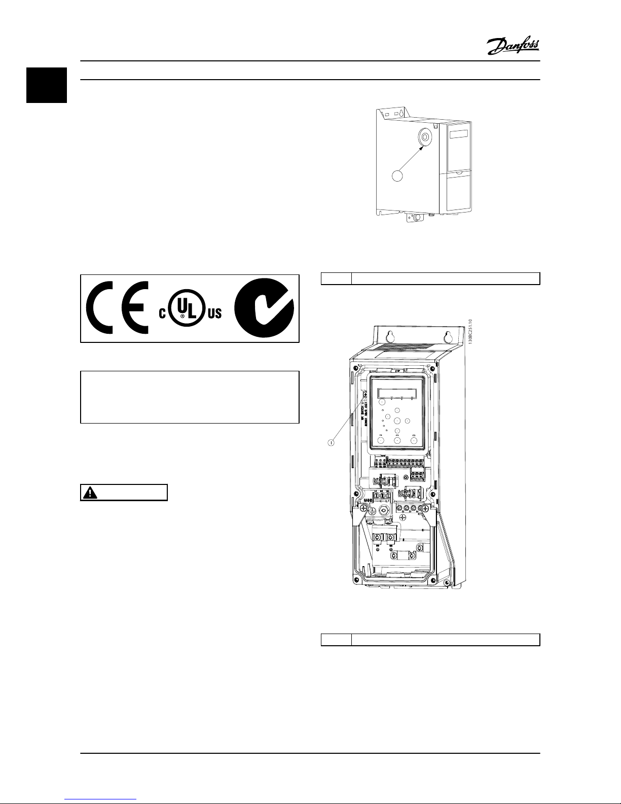
CAUTION
IT Line Power
Installation on isolated line power source, that is, IT line
power.
Max. supply voltage allowed when connected to line
power: 440 V (3x380–480 V units).
On IP20 200–240 V 0.34–15 hp [0.25–11 kW] and 380–480
V IP20 0.5–30 hp [0.37–22 kW], open the RFI switch by
removing the screw on the side of the adjustable
frequency drive when at IT grid.
130BB612.10
1
Figure 1.1 IP20 200–240 V 0.34–15 hp [0.25–11 kW], IP20 0.5–30
hp [0.37–22 kW] 380–480 V.
1 EMC screw
Table 1.4
130BC251.10
Figure 1.2 IP54 400 V 1–25 hp [0.75–18.5 kW]
1
EMC screw
Table 1.5
On all units, set to [Off] when operating in IT line power.
Quick Guide
VLT® HVAC Basic Drive Quick Guide
1-2 MG18A422 - VLT® is a registered Danfoss trademark
11
Page 6
CAUTION
If reinserted, only use M3x12 screws.
1.2.4 Avoid Unintended Start
While the adjustable frequency drive is connected to line
power, the motor can be started/stopped using digital
commands, bus commands, references or via the LCP.
•
Disconnect the adjustable frequency drive from
line power whenever personal safety considerations make it necessary to avoid unintended
start of any motors.
•
To avoid unintended start, always press [Off/
Reset] before changing parameters.
1.2.5
Disposal Instruction
Equipment containing electrical components
may not be disposed of together with domestic
waste.
It must be separately collected with electrical
and electronic waste according to local and
currently valid legislation.
Table 1.6
1.3
Installation
1.3.1 Before Starting Repair Work
1. Disconnect FC 101 from line power (and external
DC supply, if present).
2.
Wait as stated in Table 1.1 for discharge of the DC
link.
3. Remove motor cable.
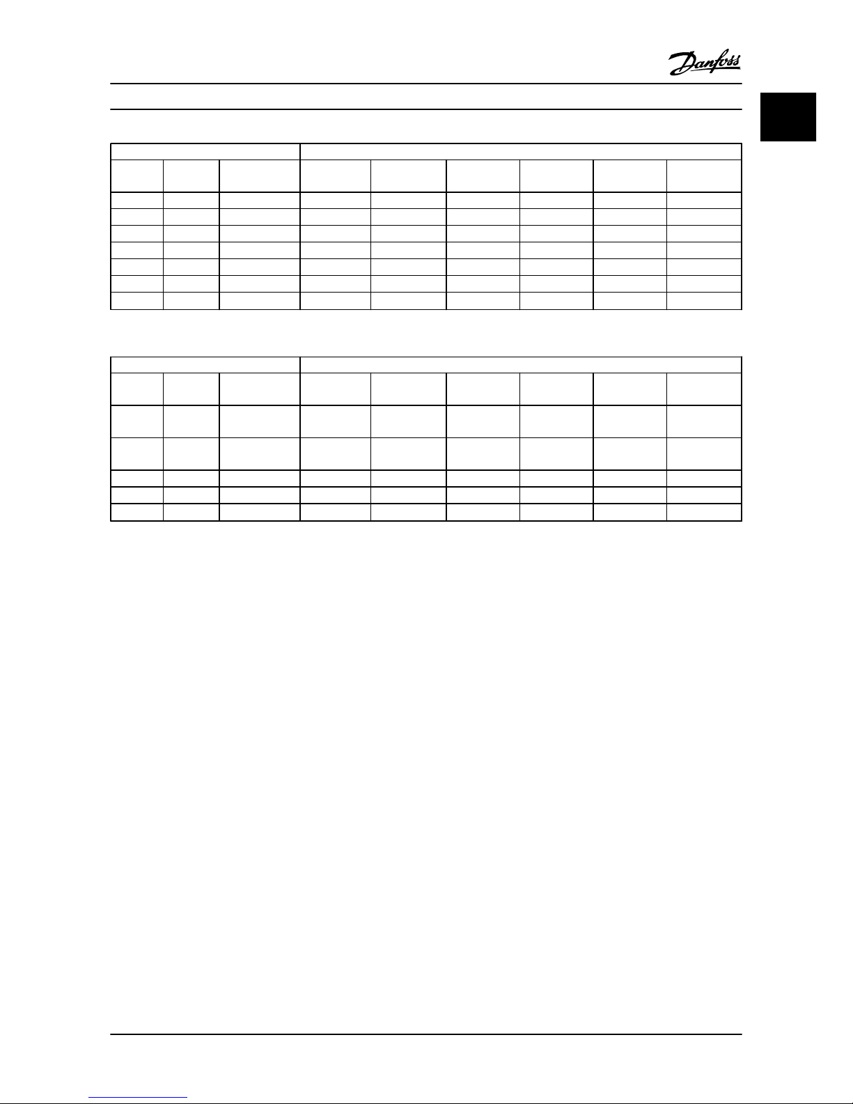
1.3.2 Side-by-Side Installation
The adjustable frequency drive can be mounted side-byside and requires the clearance above and below for
cooling.
Power (hp [kW]) Clearance above/below mm/[inch]
Frame IP class 3x200–240 V 3x380–480 V 3x525–600 V
H1 IP20 0.34–2 [0.25–1.5] 0.5–2 [0.37–1.5] 100 [4]
H2 IP20 3 [2.2] 3–5 [2.2–4] 100 [4]
H3 IP20 5 [3.7] 7.5–10 [5.5–7.5] 100 [4]
H4 IP20 7.5–10 [5.5–7.5] 15–20 [11–15] 100 [4]
H5 IP20 15 [11] 25–30 [18.5–22] 100 [4]
H6 IP20 20–25 [15–18.5] 45–60 [30–45] 25–45 [18.5–30] 200/[8]
H7 IP20 30–45 [22–30] 75–100 [55–75] 50–75 [37–55] 200/[8]
H8 IP20 50–60 [37–45] 125 [90] 100–125 [75–90] 225/[8.9]
H9 IP20 3–10 [2.2–7.5] 100 [4]
H10 IP20 15–20 [11–15] 200/[8]
Table 1.7
NOTE!
With IP21/Nema Type1 option kit mounted, a distance of 2
in [50 mm] between the units is required.
Quick Guide
VLT® HVAC Basic Drive Quick Guide
MG18A422 - VLT® is a registered Danfoss trademark 1-3
1 1
Page 7
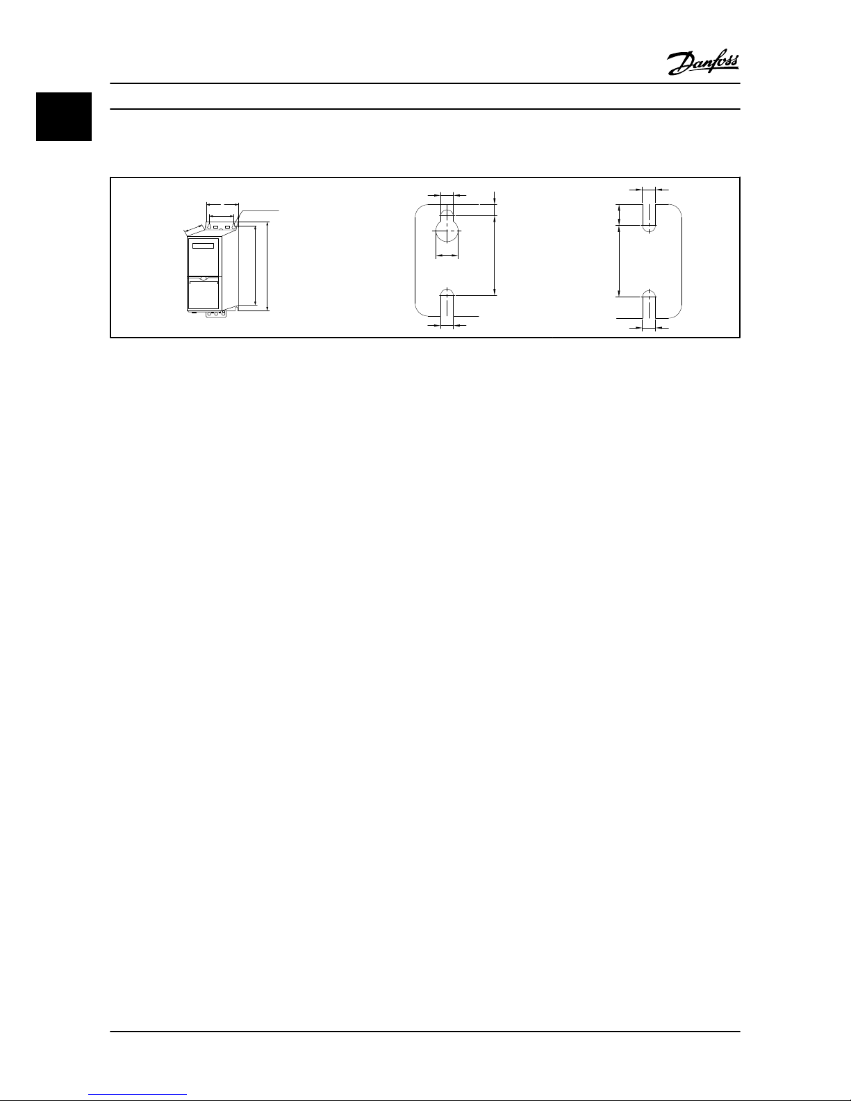
1.3.3 Dimensions
A
a
b
B
C
D
130BB614.10
e
f
a
d
e
130BC205.10
e
f
a
e
130BC246.10
Table 1.8
Quick Guide
VLT® HVAC Basic Drive Quick Guide
1-4 MG18A422 - VLT® is a registered Danfoss trademark
11
Page 8
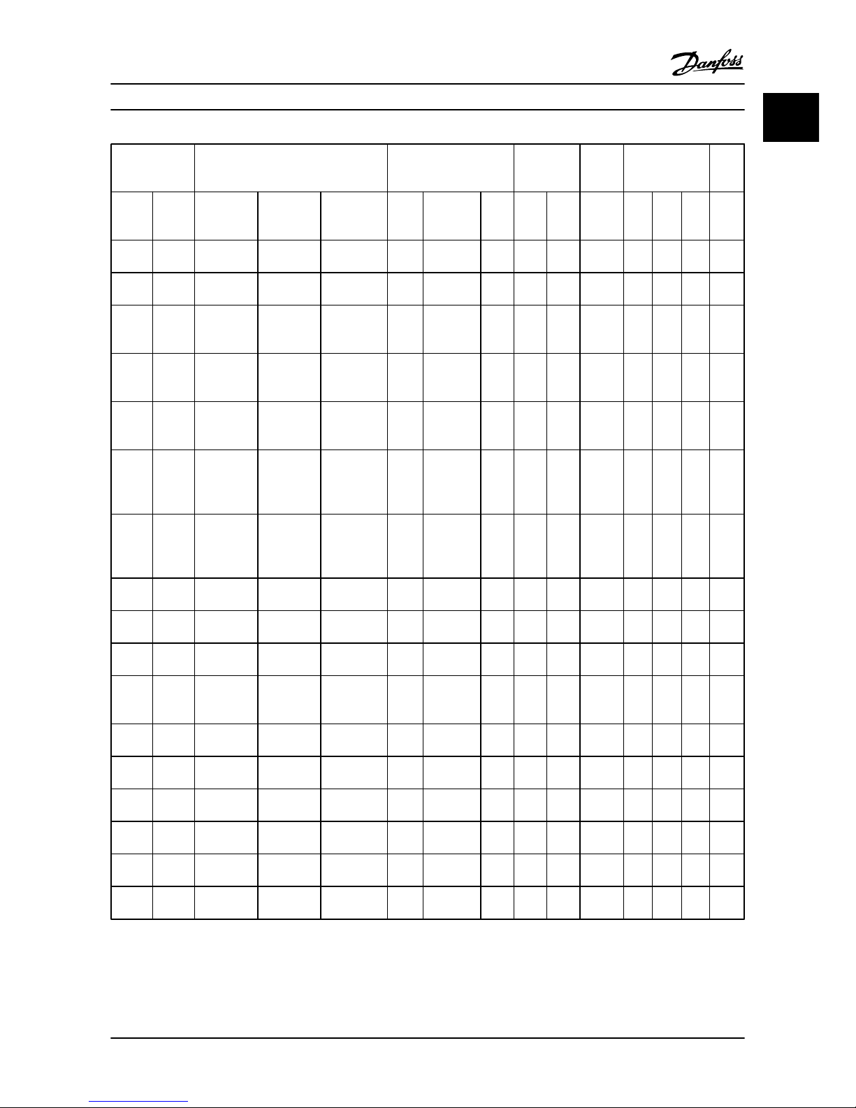
Enclosure Power (hp [kW]) Height (in [mm]) Width (in
[mm])
Depth
(in
[mm])
Mounting hole
(in [mm])
Max.
Weig
ht
Frame IP Class 3x200–240V3x380–480V3x525–600 V A "A incl De-
coupling
Plate"
a B b C d e f lb
[kg]
H1 IP20 0.34–2
[0.25–1.5]
0.5–2 [0.37–
1.5]
7.68
[195]
10.79 [273] 7.21
[183]
2.95
[75]
2.21
[56]
6.61
[168]
0.35
[9]
0.18
[4.5]
0.21
[5.3]
4.63
[2.1]
H2 IP20 3 [2.2] 3–5 [2.2–
4.0]
8.94
[227]
11.93 [303] 8.35
[212]
3.54
[90]
2.56
[65]
7.48
[190]
0.43
[11]
0.22
[5.5]
0.29
[7.4]
7.5
[3.4]
H3 IP20 5 [3.7] 7.5–10 [5.5–
7.5]
10.04
[255]
12.95 [329] 9.45
[240]
3.94
[100]
2.91
[74]
8.11
[206]
0.43
[11]
0.22
[5.5]
17.8
6
[8.1]
9.9
[4.5]
H4 IP20 7.5–10 [5.5–
7.5]
15–20 [11–
15]
11.65
[296]
14.13 [359] 10.83
[275]
5.32
[135]
4.13
[105]
9.5
[241]
0.5
[12.6
]
0.28
[7]
0.33
[8.4]
17.42
[7.9]
H5 IP20 15 [11] 25–30
[18.5–22]
13.2
[334]
15.83 [402] 12.36
[314]
5.91
[150]
[97/1
20]
10.04
[255]
0.5
[12.6
]
0.28
[7]
0.33
[8.5]
20.94
[9.5]
H6 IP20 20–25 [15–
18.5]
45–60 [30–
45]
25–45 [18.5–
30]
20.39
[518]
23.43/25
[595/635]
(60 hp [45
kW])
19.5
[495]
9.41
[239]
7.87
[200]
9.53
[242]
- 0.33
[8.5]
0.6
[15]54[24.5]
H7 IP20 30–45 [22–
30]
75–100 [55–
75]
50–75 [37–
55]
21.7
[550]
24.8/27.17
[630/690]
(100 hp
[75 kW])
20.51
[521]
12.32
[313]
10.63
[270]
13.2
[335]
- 0.33
[8.5]
0.67
[17]
79.4
[36]
H8 IP20 50–60 [37–
45]
125 [90] 100–125 [75–
90]
25.98
[660]
31.5 [800] 28.84
[631]
14.76
[375]
12.99
[330]
13.2
[335]
- 0.33
[8.5]
0.67
[17]
112.4
4 [51]
H9 IP20 3–10 [2.2–
7.5]
10.6
[269]
14.72 [374] 10.12
[257]
5.12
[130]
0.148
[110]
8.1
[205]
0.43
[11]
0.22
[5.5]
0.35
[9]
14.6
[6.6]
H10 IP20 15–20 [11–
15]
15.71
[399]
16.5 [419] 14.96
[380]
6.5
[165]
5.51
[140]
9.76
[248]
0.47
[12]
0.27
[6.8]
0.3
[7.5]
26.46
[12]
I2 IP54 1–5 [0.75–
4.0]
13.1
[332]
- 12.54
[318.5
]
4.53
[115]
2.91
[74]
88.58
[225]
0.43
[11]
0.22
[5.5]
0.35
[9]
11.69
[5.3]
I3 IP54 7.5–10 [5.5–
7.5]
14.5
[368]
- 11.94
[354]
5.32
[135]
3.5
[89]
9.33
[237]
0.47
[12]
0.26
[6.5]
0.37
[9.5]
15.87
[7.2]
I4 IP54 15–25 [11–
18.5]
18.74
[476]
- 18.11
[460]
7.1
[180]
5.24
[133]
11.42
[290]
0.47
[12]
0.26
[6.5]
0.37
[9.5]
30.42
[13.8]
I5 IP54 15–25 [11–
18.5]
18.9
[480]
- 17.9
[454]
9.53
[242]
8.27
[210]
10.24
[260]
0.75
[19]
0.35
[9]
0.35
[9]
50.71
[23]
I6 IP54 30–50 [22–
37]
25.6
[650]
- 2.6
[624]
9.53
[242]
8.27
[210]
10.24
[260]
0.75
[19]
0.35
[9]
0.35
[9]
59.52
[27]
I7 IP54 60–75 [45–
55]
26.8
[680]
- 25.51
[648]
12.13
[308]
10.71
[272]
12.21
[310]
0.75
[19]
0.35
[9]
0.39
[9.8]
99.21
[45]
I8 IP54 100–125
[75–90]
30.32
[770]
- 29.1
[739]
14.57
[370]
13.2
[334]
13.2
[335]
0.75
[19]
0.35
[9]
0.39
[9.8]
143.3
[65]
Table 1.9
Quick Guide
VLT® HVAC Basic Drive Quick Guide
MG18A422 - VLT® is a registered Danfoss trademark 1-5
1 1
Page 9
The dimensions are only for the physical units, but when
installing in an application it is necessary to add space for
free air passage both above and below the units. The
amount of space for free air passage is listed in Table 1.10:
Enclosure Clearance needed for free air passage (in [mm])
Frame IP class Above unit Below unit
H1 0.79 [20] 3.94 [100] 3.94 [100]
H2 0.79 [20] 3.94 [100] 3.94 [100]
H3 0.79 [20] 3.94 [100] 3.94 [100]
H4 0.79 [20] 3.94 [100] 3.94 [100]
H5 0.79 [20] 3.94 [100] 3.94 [100]
H6 0.79 [20] 7.87 [200] 7.87 [200]
H7 0.79 [20] 7.87 [200] 7.87 [200]
H8 0.79 [20] 88.58 [225] 88.58 [225]
H9 0.79 [20] 3.94 [100] 3.94 [100]
H10 0.79 [20] 7.87 [200] 7.87 [200]
I2 2.13 [54] 3.94 [100] 3.94 [100]
I3 2.13 [54] 3.94 [100] 3.94 [100]
I4 2.13 [54] 3.94 [100] 3.94 [100]
I5 2.13 [54] 7.87 [200] 7.87 [200]
I6 2.13 [54] 7.87 [200] 7.87 [200]
I7 2.13 [54] 7.87 [200] 7.87 [200]
I8 2.13 [54] 88.58 [225] 88.58 [225]
Table 1.10 Clearance Needed for Free Air Passage (in [mm])
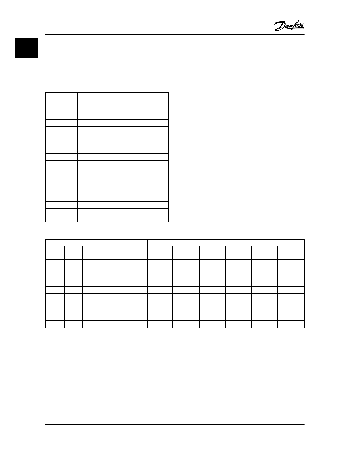
1.3.4
Electrical Installation in General
All cabling must comply with national and local
regulations on cable cross-sections and ambient
temperature. Copper conductors required, (167° F [75°C])
recommended.
Power (hp [kW]) Torque [Nm]
Frame IP class 3x200–240 V 3x380–480 V Line Motor DC
connection
Control
terminals
Ground Relay
H1 IP20 0.34–2 [0.25–
1.5]
0.5–2 [0.37–1.5] 1.4 0.8 0.8 0.5 0.8 0.5
H2 IP20 3 [2.2] 3–5 [2.2–4] 1.4 0.8 0.8 0.5 0.8 0.5
H3 IP20 5 [3.7] 7.5–10 [5.5–7.5] 1.4 0.8 0.8 0.5 0.8 0.5
H4 IP20 7.5–10 [5.5–7.5] 15–20 [11–15] 1.2 1.2 1.2 0.5 0.8 0.5
H5 IP20 15 [11] 25–30 [18.5–22] 1.2 1.2 1.2 0.5 0.8 0.5
H6 IP20 20–25 [15–18] 45–60 [30–45] 4.5 4.5 - 0.5 3 0.5
H7 IP20 30–45 [22–30] 75 [55] 10 10 - 0.5 3 0.5
H7 IP20 - 100 [75] 14 14 - 0.5 3 0.5
H8 IP20 50–60 [37–45] 125 [90]
24
2
24
2
- 0.5 3 0.5
Table 1.11
Quick Guide
VLT® HVAC Basic Drive Quick Guide
1-6 MG18A422 - VLT® is a registered Danfoss trademark
11
Page 10
Power (hp [kW]) Torque [Nm]
Frame IP class 3x380–480 V Line Motor DC connection Control
terminals
Ground Relay
I2 IP54 1–5 [0.75–4.0] 1.4 0.8 0.8 0.5 0.8 0.5
I3 IP54 7.5–10 [5.5–7.5] 1.4 0.8 0.8 0.5 0.8 0.5
I4 IP54 15–25 [11–18.5] 1.4 0.8 0.8 0.5 0.8 0.5
I5 IP54 15–25 [11–18.5] 1.8 1.8 - 0.5 3 0.6
I6 IP54 30–50 [22–37] 4.5 4.5 - 0.5 3 0.6
I7 IP54 60–75 [45–55] 10 10 - 0.5 3 0.6
I8 IP54 100–125 [75–90]
14/24
1
14/24
1
- 0.5 3 0.6
Table 1.12
Power (hp [kW]) Torque [Nm]
Frame IP class 3x525–600 V Line Motor DC connection Control
terminals
Ground Relay
H9 IP20 3–10 [2.2–7.5] 1.8 1.8 not
recommended
0.5 3 0.6
H10 IP20 15–20 [11–15] 1.8 1.8 not
recommended
0.5 3 0.6
H6 IP20 25–45 [18.5–30] 4.5 4.5 - 0.5 3 0.5
H7 IP20 50–75 [37–55] 10 10 - 0.5 3 0.5
H8 IP20 100–125 [75–90]
14/24
1
14/24
1
- 0.5 3 0.5
Table 1.13 Details of Tightening Torques
1
Cable dimensions ≤0.1472 [95 mm2]
2
Cable dimensions >0.1472 [95 mm2]
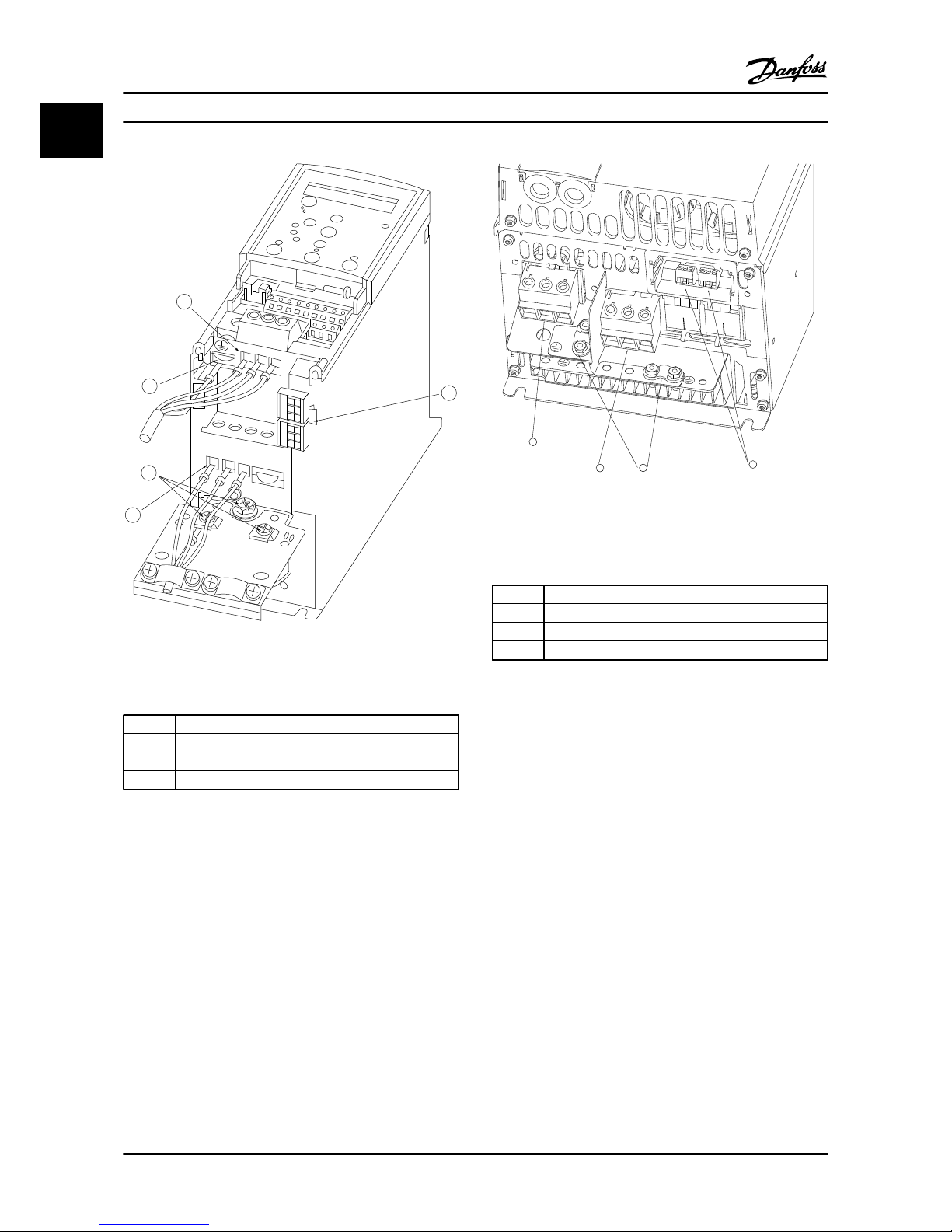
1.3.5 Connecting to Line Power and Motor
The adjustable frequency drive is designed to operate all
standard three-phased asynchronous motors. For
maximum cross-section on wires, see 1.6 General Specifi-
cations.
•
Use a shielded/armored motor cable to comply
with EMC emission specifications, and connect
this cable to both the decoupling plate and the
motor metal.
•
Keep motor cable as short as possible to reduce
the noise level and leakage currents.
•
For further details on mounting of the
decoupling plate, see FC 101 De-coupling Plate
Mounting Instruction MI02Q.
•
Also see EMC-compatible Installation in the VLT
®
HVAC Basic Design Guide, MG18C.
1. Mount the ground wires to the ground terminal.
2. Connect the motor to terminals U, V and W.
3. Mount line power supply to terminals L1, L2 and
L3 and tighten.
Quick Guide
VLT® HVAC Basic Drive Quick Guide
MG18A422 - VLT® is a registered Danfoss trademark 1-7
1 1
Page 11
130BB634.10
1
2
2
3
4
Motor
U
V
W
-DC
+DC
MAINS
Figure 1.3 H1-H5 Frame
IP20 200–240 V 0.34–15 hp [0.25–11 kW] and IP20 380–480 V
0.5–30 hp [0.37–22 kW].
1
Line
2 Ground
3 Motor
4 Relays
Table 1.14
1
95
99
L1 91 / L2 92 / L3 93
U 96 / V 97 / W 98
03 02 01
06 05 04
2
3
4
130BB762.10
Figure 1.4 H6 Frame
IP20 380–480 V 40–60 hp [30–45 kW]
IP20 200–240 V 20–25 hp [15–18.5 kW]
IP20 525–600 V 30–40 hp [22–30 kW|
1 Line
2 Motor
3 Ground
4 Relays
Table 1.15
Quick Guide
VLT® HVAC Basic Drive Quick Guide
1-8 MG18A422 - VLT® is a registered Danfoss trademark
11
Page 12
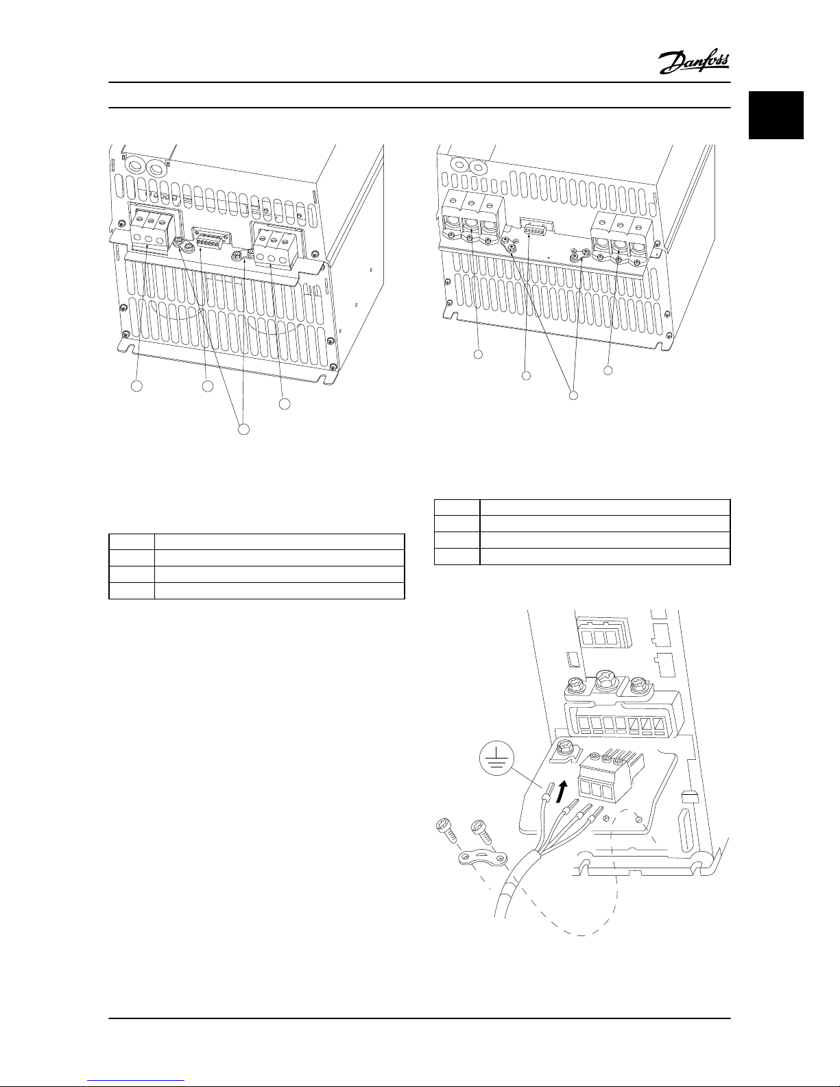
1
2
3
4
130BB763.10
Figure 1.5 H7 Frame
IP20 380–480 V 75–100 hp [55–75 kW]
IP20 200–240 V 30–40 hp [22–30 kW]
IP20 525–600 V 60–75 hp [45–55 kW]
1
Line
2 Relays
3 Ground
4 Motor
Table 1.16
130BB764.10
1
2
3
4
98
97
96
99
95
93
92
91
L1
L1
L1
U
V
w
Figure 1.6 H8 Frame
IP20 380-480 V 125 hp [90 kW]
IP20 200–240 V 50–60 hp [37–45 kW]
IP20 525–600 V 100–125 hp [75–90 kW]
1 Line
2 Relays
3 Ground
4 Motor
Table 1.17
MOTOR
MOTOR
U V W
99
130BT302.12
Figure 1.7 H9 Frame
IP20 600 V 3–10 hp [2.2–7.5 kW]
Quick Guide
VLT® HVAC Basic Drive Quick Guide
MG18A422 - VLT® is a registered Danfoss trademark 1-9
1 1
Page 13
-DC+DC
BR- BR+ U V W
99
M A I N S
95
RELAY 1 RELAY 2
- LC +
130BA261.10
Figure 1.8
130BA262.10
M
I N S
+DC
BR-
BR+
U
V
W
RELAY 1 RELAY 2
95
Figure 1.9
130BA263.10
95
M
A
INS
+DC
BR-
BR+
U
V
W
91
92
93
L1
L2
L3
RELAY 1 RELAY 2
Figure 1.10
Quick Guide
VLT® HVAC Basic Drive Quick Guide
1-10 MG18A422 - VLT® is a registered Danfoss trademark
11
Page 14
+DC
BR-
BR+
U
V
W
MAINS
L1 L2 L3
91 92 93
RELAY 1 RELAY 2
99
- LC -
130BA264.10
Figure 1.11
130BA725.10
Figure 1.12 H10 Frame
IP20 600 V 15–20 hp [11–15 kW]
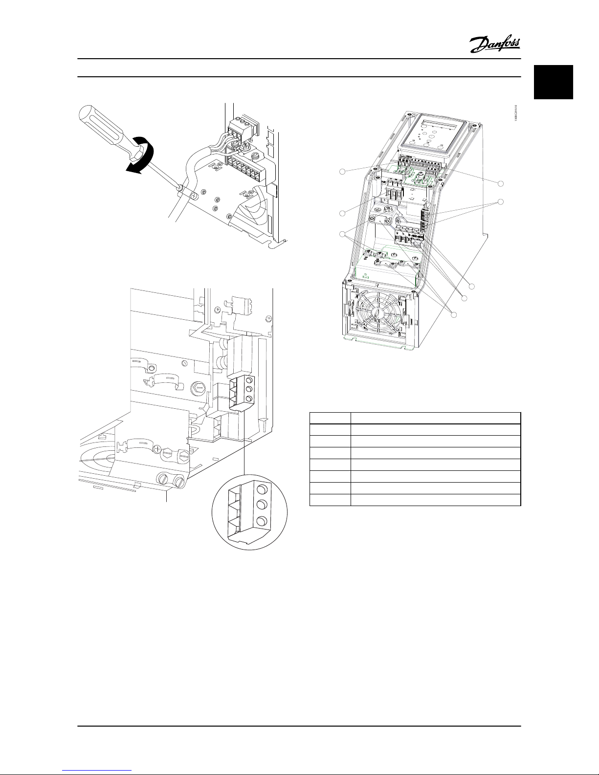
130BC299.10
7
3
2
5
1
8
4
6
Figure 1.13 I2 Frame
IP54 380–480 V 1–5 hp [0.75–4.0 kW]
1
RS-485
2 Line in
3 Ground
4 Wire clamps
5 Motor
6 UDC
7 Relays
8 I/O
Table 1.18
Quick Guide
VLT® HVAC Basic Drive Quick Guide
MG18A422 - VLT® is a registered Danfoss trademark 1-11
1 1
Page 15
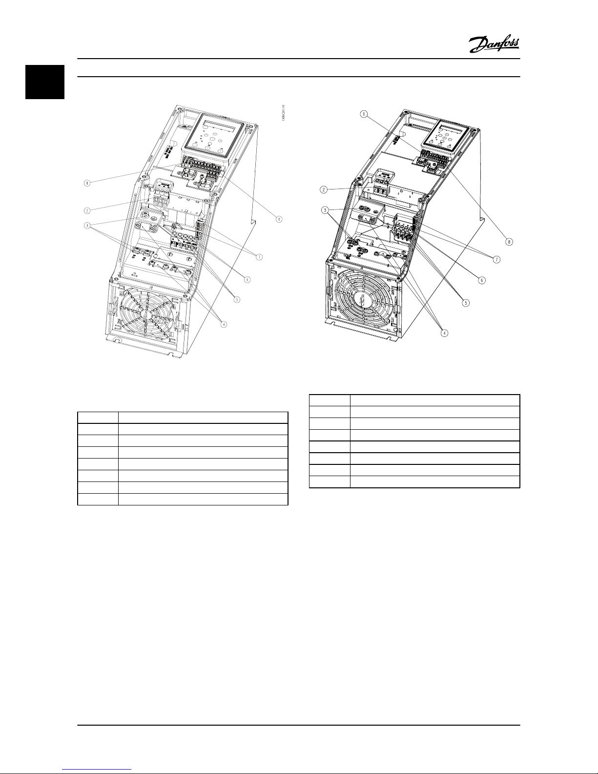
130BC201.10
Figure 1.14 I3 Frame
IP54 380–480 V 75–100 hp [5.5–7.5 kW]
1
RS-485
2 Line in
3 Ground
4 Wire clamps
5 Motor
6 UDC
7 Relays
8 I/O
Table 1.19
130BD011.10
Figure 1.15 I4 Frame
IP54 380–480 V 1–5 hp [0.75–4.0 kW]
1
RS-485
2 Line in
3 Ground
4 Wire clamps
5 Motor
6 UDC
7 Relays
8 I/O
Table 1.20
Quick Guide
VLT® HVAC Basic Drive Quick Guide
1-12 MG18A422 - VLT® is a registered Danfoss trademark
11
Page 16
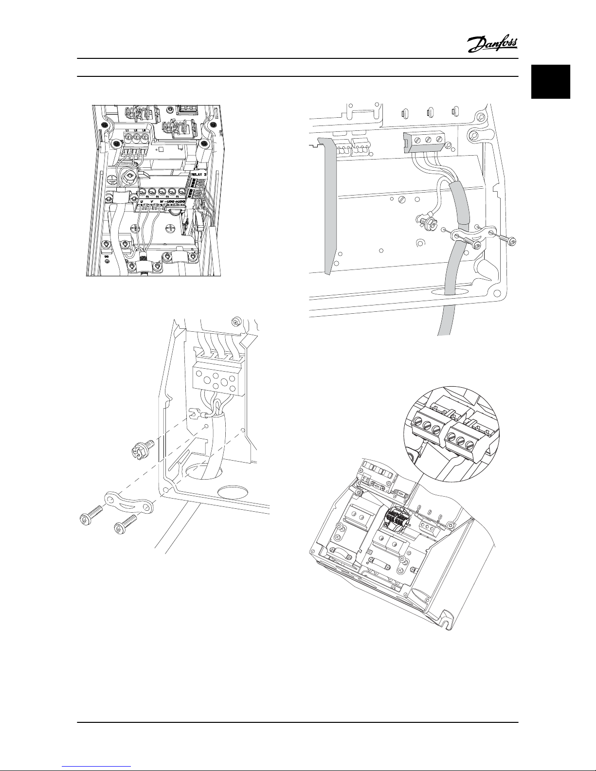
130BC203.10
Figure 1.16 IP54 I2-I3-I4 frame
130BT326.10
Figure 1.17 I6 Frame
IP54 380-480 V 30–50 hp [22–37 kW]
130BT325.10
Figure 1.18 I6 Frame
IP54 380-480 V 30–50 hp [22–37 kW]
311
130BA215.10
RELAY 1
RELAY 2
9
9
6
03 02 01
90 05 04
Figure 1.19 I6 Frame
IP54 380-480 V 30–50 hp [22–37 kW]
Quick Guide
VLT® HVAC Basic Drive Quick Guide
MG18A422 - VLT® is a registered Danfoss trademark 1-13
1 1
Page 17

91
L1
92
L2
93
L3
96
U
97
V
98
W
88
DC-
89
DC+
81
R-
8
R+
99
95
130BA248.10
Figure 1.20 I7, I8 Frame
IP54 380–480 V 60–75 hp [45–55 kW]
IP54 380–480 V 100–125 hp [75–90 kW]
1.3.6
Fuses
Branch circuit protection
In order to protect the installation from electrical and fire
hazards, all branch circuits in an installation, switch gears,
machines etc., must be protected from short-circuits and
overcurrents according to national/international
regulations.
Short circuit protection
Danfoss recommends using the fuses mentioned in the
following tables to protect service personnel or other
equipment in case of an internal failure in the unit or
short-circuit on DC link. The adjustable frequency drive
provides full short-circuit protection in case of a shortcircuit on the motor.
Overcurrent protection
Provide overload protection to avoid overheating of the
cables in the installation. Overcurrent protection must
always be carried out according to national regulations.
Fuses must be designed for protection in a circuit capable
of supplying a maximum of 100,000 A
rms
(symmetrical),
480 V maximum.
Non-UL compliance
If UL/cUL is not to be complied with, Danfoss recommends
using the fuses mentioned in Table 1.21, which ensures
compliance with IEC 61800-5-1.
In case of malfunction, not following the fuse recommendation may result in damage to the adjustable frequency
drive.
Circuit Breaker Fuse
UL Non-UL UL Non-UL
Bussmann Bussmann Bussmann Bussmann Max fuse
Power (hp [kW]) Type RK5 Type RK1 Type J Type T Type G
3x200–240 V IP20
0.34 [0.25]
FRS-R-10 KTN-R10 JKS-10 JIN-10 10
0.5 [0.37] FRS-R-10 KTN-R10 JKS-10 JIN-10 10
1 [0.75] FRS-R-10 KTN-R10 JKS-10 JIN-10 10
2 [1.5] FRS-R-10 KTN-R10 JKS-10 JIN-10 10
3 [2.2] FRS-R-15 KTN-R15 JKS-15 JIN-15 16
5 [3.7] FRS-R-25 KTN-R25 JKS-25 JIN-25 25
7.5 [5.5] FRS-R-50 KTN-R50 JKS-50 JIN-50 50
10 [7.5] FRS-R-50 KTN-R50 JKS-50 JIN-50 50
15 [11] FRS-R-80 KTN-R80 JKS-80 JIN-80 65
Quick Guide
VLT® HVAC Basic Drive Quick Guide
1-14 MG18A422 - VLT® is a registered Danfoss trademark
11
Page 18

Circuit Breaker Fuse
UL Non-UL UL Non-UL
Bussmann Bussmann Bussmann Bussmann Max fuse
Power (hp [kW]) Type RK5 Type RK1 Type J Type T Type G
20 [15]
Cutler-Hammer
EGE3100FFG
Moeller NZMB1-
A125
FRS-R-100 KTN-R100
125
25 [18.5] FRS-R-100 KTN-R100 125
30 [22]
Cutler-Hammer
JGE3150FFG
Moeller NZMB1-
A160
FRS-R-150 KTN-R150 160
40 [30] FRS-R-150 KTN-R150 160
50 [37]
Cutler-Hammer
JGE3200FFG
Moeller NZMB1-
A200
FRS-R-200 KTN-R200 200
60 [45] FRS-R-200 KTN-R200 200
3x380–480 V IP20
0.5 [0.37]
FRS-R-10 KTS-R10 JKS-10 JJS-10 10
1 [0.75] FRS-R-10 KTS-R10 JKS-10 JJS-10 10
2 [1.5] FRS-R-10 KTS-R10 JKS-10 JJS-10 10
3 [2.2] FRS-R-15 KTS-R15 JKS-15 JJS-15 16
4 [3] FRS-R-15 KTS-R15 JKS-15 JJS-15 16
5 [4] FRS-R-15 KTS-R15 JKS-15 JJS-15 16
7.5 [5.5] FRS-R-25 KTS-R25 JKS-25 JJS-25 25
10 [7.5] FRS-R-25 KTS-R25 JKS-25 JJS-25 25
15 [11] FRS-R-50 KTS-R50 JKS-50 JJS-50 50
20 [15] FRS-R-50 KTS-R50 JKS-50 JJS-50 50
25 [18.5] FRS-R-80 KTS-R80 JKS-80 JJS-80 65
30 [22] FRS-R-80 KTS-R80 JKS-80 JJS-80 65
40 [30]
Cutler-Hammer
EGE3125FFG
Moeller NZMB1-
A125
FRS-R-80 KTS-R80 JKS-R80 JJS-R80 80
50 [37] FRS-R-100 KTS-R100 JKS-R100 JJS-R100 100
60 [45] FRS-R-125 KTS-R125 JKS-R125 JJS-R125 125
75 [55]
Cutler-Hammer
JGE3200FFG
Moeller NZMB1-
A200
FRS-R-150 KTS-R150 JKS-R150 JJS-R150 150
100 [75] FRS-R-200 KTS-R200 JKS-R200 JJS-R200 200
125 [90]
Cutler-Hammer
JGE3250FFG
Moeller NZMB2-
A250
FRS-R-250 KTS-R250 JKS-R250 JJS-R250 250
Table 1.21
Quick Guide
VLT® HVAC Basic Drive Quick Guide
MG18A422 - VLT® is a registered Danfoss trademark 1-15
1 1
Page 19

Circuit Breaker Fuse
UL Non-UL UL Non-UL
Bussmann Bussmann Bussmann Bussmann Max fuse
Power (hp [kW]) Type RK5 Type RK1 Type J Type T Type G
3x525–600 V IP20
3 [2.2]
KTS-R20
20
3 KTS-R20 20
5 [3.7] KTS-R20 20
5.5 KTS-R20 20
10 [7.5] KTS-R20 30
11
KTS-R30 35
20 [15] KTS-R30 35
18.5
Cutler-Hammer
EGE3080FFG
Cutler-Hammer
EGE3080FFG
FRS-R-80 KTN-R80 80
30 [22] FRS-R-80 KTN-R80 80
40 [30] FRS-R-80 KTN-R80 80
50 [37]
Cutler-Hammer
JGE3125FFG
Cutler-Hammer
JGE3125FFG
FRS-R-125 KTN-R125 125
60 [45] FRS-R-125 KTN-R125 125
75 [55] FRS-R-125 KTN-R125 125
100 [75]
Cutler-Hammer
JGE3200FAG
Cutler-Hammer
JGE3200FAG
FRS-R-200 KTN-R200 200
125 [90] FRS-R-200 KTN-R200 200
3x380–480 V IP54
1 [0.75]
2 [1.5]
3 [2.2]
4 [3]
5 [4]
7.5 [5.5]
10 [7.5]
15 [11]
20 [15]
25 [18.5]
30 [22]
Moeller NZMB1-A125
125
40 [30] 125
50 [37] 125
60 [45]
Moeller NZMB2-A160
160
75 [55] 160
100 [75]
Moeller NZMB2-A250
200
125 [90] 200
Table 1.22 Fuses
1.3.7
EMC-compatible Electrical Installation
General points to be observed to ensure EMC-compatible
electrical installation.
•
Use only shielded/armored motor cables and
shielded/armored control cables.
•
Connect the shield to ground at both ends.
•
Avoid installation with twisted shield ends
(pigtails), since this ruins the shielding effect at
high frequencies. Use the cable clamps provided
instead.
•
It is important to ensure good electrical contact
from the installation plate through the installation
screws to the metal cabinet of the adjustable
frequency drive.
•
Use star-washers and galvanically grounding
plates.
•
Do not use shielded/armored motor cables in the
installation cabinets.
Quick Guide
VLT® HVAC Basic Drive Quick Guide
1-16 MG18A422 - VLT® is a registered Danfoss trademark
11
Page 20

L1
L2
L3
PE
Min. 0.0248 in
2
[16 mm2]
Equalizing cable
Control cables
All cable entries in
one side of panel
Grounding rail
Cable insulation stripped
Output contactor, etc.
Motor cable
Motor, 3 phases and
PLC etc.
Panel
Line power supply
Min. 7.9 in [200 mm]
between control
cable, line cable
and between line power
motor cable
PLC
Protective ground
Reinforced protective ground
130BB761.10
Figure 1.21 EMC-compatible Electrical Installation
NOTE!
For North America, use metal conduits instead of shielded
cables.
Quick Guide
VLT® HVAC Basic Drive Quick Guide
MG18A422 - VLT® is a registered Danfoss trademark 1-17
1 1
Page 21

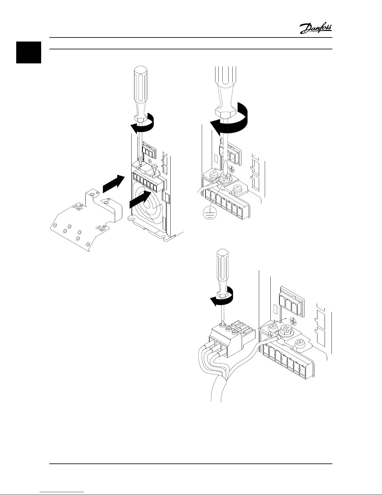
1.3.8 Control Terminals
IP20 200–240 V 0.34–15 hp [0.25–11 kW] and IP20 380–480
V 0.5–30 hp [0.37–22 kW]:
130BB622.10
Figure 1.22 Location of Control Terminals
1. Place a screwdriver behind the terminal cover to
activate snap.
2. Tilt the screwdriver outwards to open the cover.
130BB624.10
Figure 1.23 IP20 380–480 V 40–125 hp [30–90 kW]
1. Place a screwdriver behind the terminal cover to
activate snap.
2. Tilt the screwdriver outwards to open the cover.
Digital input 18, 19 and 27 mode is set in 5-00 Digital Input
Mode (PNP is default value) and digital input 29 mode is
set in 5-03 Digital Input 29 Mode (PNP is default value).
130BC249.10
Figure 1.24 IP54 400 V 1–10 hp [0.75–7.5 kW]
1. Remove the front cover.
Control terminals
Figure 1.25 shows all control terminals of the adjustable
frequency drive. Applying Start (term. 18), connection
between terminal 12-27 and an analog reference (term. 53
or 54 and 55) make the adjustable frequency drive run.
18
19
12 20 55
27 29 42 45 50 53 54
DIGI IN
DIGI IN
DIGI IN
DIGI IN
61 68 69
N
P
COMM. GND
+24V
0/4-20mA A OUT / DIG OUT 0/4-20mA A OUT / DIG OUT
GND
GND
10V/20mA IN
10V/20mA IN
10V OUT
130BB625.10
BUS TER.
OFF ON
Figure 1.25 Control Terminals
Quick Guide
VLT® HVAC Basic Drive Quick Guide
1-18 MG18A422 - VLT® is a registered Danfoss trademark
11
Page 22

1.3.9 Electrical Overview
L1
L2
L3
3 Phase
power
input
PE
PE
+10Vdc
0-10Vdc-
0-10Vdc-
50 (+10V OUT)
54 (A IN)
53 (A IN)
55 (COM A IN/OUT)
0/4-20 mA
0/4-20 mA
42 0/4-20mA A OUT / DIG OUT
45 0/4-20mA A OUT / DIG OUT
18 (DIGI IN)
19 (DIGI IN)
27 (DIGI IN)
29 (DIGI IN)
12 (+24V OUT)
24V (NPN)
20 (COM D IN)
OV (PNP)
24V (NPN)
OV (PNP)
24V (NPN)
OV (PNP)
24V (NPN)
OV (PNP)
Bus ter.
Bus ter.
RS-485
Interface
RS-485
(N PS-485) 69
(P RS-485) 68
(Com RS-485) 61
(PNP) Source
(NPN) Sink
ON=Terminated
OFF=Unterminated
ON
1 2
240Vac 2A
Not present on all power sizes
Do not connect shield to
61 on 116, 117 and 118 units
01
02
03
relay1
relay2
UDC+
UDC-
Motor
U
V
W
130BB626.10
06
05
04
240Vac 2A
Figure 1.26
NOTE!
There is no access to UDC- and UDC+ on the following units:
IP20 380–480 V 40–125 hp [30–90 kW]
IP20 200–240 V 20–60 hp [15–45 kW]
IP20 525–600 V 3–125 hp [2.2–90 kW]
IP54 380–480 V 30–125 hp [22–90 kW]
Quick Guide
VLT® HVAC Basic Drive Quick Guide
MG18A422 - VLT® is a registered Danfoss trademark 1-19
1 1
Page 23

1.4 Programming
1.4.1 Programming with the Local Control
Panel (LCP)
NOTE!
The adjustable frequency drive can also be programmed
from a PC via RS-485 COM port by installing the MCT 10
Set-up Software. This software can either be ordered using
code number 130B1000 or downloaded from the Danfoss
website: www.danfoss.com/BusinessAreas/DrivesSolutions/
softwaredownload
1.4.2 Local Control Panel (LCP)
The following instructions are valid for the FC 101 LCP. The
LCP is divided into four functional sections.
A. Alphanumeric display
B. Menu key
C. Navigation keys and LEDs
D. Operation keys and LEDs
130BB765.11
B
a
c
k
Com.
1-20 Motor Power
[5] 0.37kW - 0.5HP
Setup 1
A
B
1
12
13 14 15
11
11
10
9
8
7
6
5
4
3
2
C
D
Status
Main
Menu
Quick
Menu
Hand
On
OK
Menu
O
Reset
Auto
On
Alarm
Warn.
On
11
Figure 1.27
A. Alpha Numeric Display
The LCD display is backlit with two alpha-numeric lines. All
data is displayed on the LCP.
Information can be read from the display.
1 Parameter number and name.
2 Parameter value.
3 Set-up number shows the active set-up and the edit set-
up. If the same set-up acts as both the active and edit setup, only that set-up number is shown (factory setting).
When the active and edit set-up differ, both numbers are
shown in the display (Set-up 12). The flashing number
indicates the edit set-up.
4 Motor direction is shown to the bottom left of the display
– indicated by a small arrow pointing either clockwise or
counter-clockwise.
5 The triangle indicates if the LCP is in status, quick menu or
main menu.
Table 1.23
B. Menu key
Use the menu key to select between status, quick menu or
main menu.
C. Navigation keys and LEDs
6 COM LED: Flashes when bus communication is communi-
cating.
7 Green LED/On: Control section is working.
8 Yellow LED/Warn.: Indicates a warning.
9 Flashing Red LED/Alarm: Indicates an alarm.
10 [Back]: For moving to the previous step or layer in the
navigation structure
11
[▲] [▼] [►]: For navigating between parameter groups,
parameters and within parameters. Can also be used for
setting local reference.
12 [OK]: For selecting a parameter and for accepting changes to
parameter settings
Table 1.24
D. Operation keys and LEDs
13
[Hand On]: Starts the motor and enables control of the
adjustable frequency drive via the LCP.
NOTE!
Terminal 27 Digital Input (5-12 Terminal 27 Digital
Input) has coast inverse as default setting. This means
that [Hand On] not starts the motor if there is no 24
V to terminal 27. Connect terminal 12 to terminal 27.
14 [Off/Reset]: Stops the motor (Off). If in alarm mode the
alarm will be reset.
15 [Auto On]: The adjustable frequency drive is controlled
either via control terminals or serial communication.
Table 1.25
Quick Guide
VLT® HVAC Basic Drive Quick Guide
1-20 MG18A422 - VLT® is a registered Danfoss trademark
11
Page 24

At power-up
At the first power-up, select the preferred language. Once
selected, this screen never shows again in the following
power-ups, but language can still be changed in
0-01 Language.
130BB628.10
Select Language
[ 0 ] English
Set-up 1
Figure 1.28
1.4.3 The Start-up Wizard for Open-loop
Applications
The built-in “wizard” menu guides the installer through the
set-up of the adjustable frequency drive in a clear and
structured manner to set up an open-loop application. An
open-loop application is here an application with a start
signal, analog reference (voltage or current) and optionally
also relay signals (but no feedback signal from the process
applied).
FC
+24V
DIG IN
DIG IN
DIG IN
DIG IN
COM DIG IN
A OUT / D OUT
A OUT / D OUT
18
19
27
29
42
55
50
53
54
20
12
01
02
03
04
05
06
R2
R1
0-10 V
Reference
Start
+10V
A IN
A IN
COM
130BB674.10
45
+
-
Figure 1.29
The wizard will initially be shown after power-up until any
parameter has been changed. The wizard can always be
accessed again through the Quick Menu. Press [OK] to start
the wizard. If [Back] is pressed, the FC 101 returns to the
status screen.
130BB629.10
Press OK to start Wizard
Push Back to skip it
Set-up 1
Figure 1.30
Quick Guide
VLT® HVAC Basic Drive Quick Guide
MG18A422 - VLT® is a registered Danfoss trademark 1-21
1 1
Page 25

Setup 1
Power kW/50 Hz
Setup 1
Set Motor Speed low Limit
Hz
Setup 1
Set Motor Speed high Limit
Hz
Setup 1
Set Ramp 1 ramp-up time
s
Setup 1
Set Ramp 1 ramp-down Time
s
Setup 1
Active Flying start?
Disable
OK
5
Setup 1
Set Motor Power
7
Setup 1
Set Motor Voltage
8
Setup 1
Set Motor frequency
9
Setup 1
Set Motor current
10
Setup 1
Set Motor nominal speed
11
if
17
20
21
22
Select Regional Settings
... the HVAC FC 101 Wizard starts
Setup 1
200-240V/50Hz/Delta
Grid Type
4
Asynchronous Motor
Setup 1
Asynchronous
Select Motor Type
6
Setup 1
Set Motor current
12
Setup 1
Select Motor nominal speed
13
Setup 1
Set Motor Cont. Rated Torque
14
Setup 1
Stator resistance
15
Setup 1
Motor poles
16
Setup 1
Back EMF at 1000 rpm
18
Setup 1
d-axis inductance
19
Setup 1
Set Max Output Frequency
23
24
Setup 1
Setup 1Setup 1
Setup 1
Set T53 low Voltage
V
Set T53 high Voltage
V
Set T53 Low Current
A
Set T53 High Current
A
Current
Voltage
28
29
26
27
Setup 1
Setup 1
Setup 1
Setup 1
Setup 1
Setup 1
Setup 1
Setup 1
Setup 1
AMA Failed
0.0 Hz
0.0 kW
Wizard completed
Press OK to accept
Automatic Motor Adaption
O
Auto Motor Adapt OK
Press OK
Select Function of Relay 2
No function
Select Function of Relay 1
[0] No function
Set Max Reference
Hz
Set Min Reference
Hz
AMA running
-----
AMA failed
Do AMA
(Do not AMA)
AMA OK
30
31
32
33
34
37
38
39
35 36
[0]
[0]
[0]
Setup 1
Select T53 Mode
Current
25
[0]
[0]
3.8
A
3000
RPM
5.4
Nm
0.65
Ohms
8
57
V
5
mH
0065
Hz
1.50
kW
0050
V
0050
Hz
04.66
A
1420
RPM
[0]
PM motor
Motor Type = Asynchronous
Motor Type = PM Motor
0000
0050
0003
0003
[0]
[0]
04.66
13.30
0050
0220
0000
0050
OK
B
a
c
k
Status
Main
Menu
Quick
Menu
Hand
On
OK
Menu
O
Reset
Auto
On
Alarm
Warn.
On
Status Screen
The Wizard can always be
reentered via the Quick Menu!
Power Up Screen
At power up the user is
asked to choose the
prefered laguage.
Select language
[1] English
0.0 Hz
0.0 kW
Setup 1
Setup 1
Status
Main
Menu
Quick
Menu
Hand
On
OK
Menu
O
Reset
Auto
On
Alarm
Warn.
On
Press OK to start Wizard
Press Back to skip it
Setup 1
Status
Main
Menu
Quick
Menu
Hand
On
OK
Menu
O
Reset
Auto
On
Alarm
Warn.
On
The next screen will be
the Wizard screen.
Wizard Screen
1
2
if
3
B
a
c
k
B
a
c
k
B
a
c
k
Com.
Com.
Com.
130BC244.11
Figure 1.31
Quick Guide
VLT® HVAC Basic Drive Quick Guide
1-22 MG18A422 - VLT® is a registered Danfoss trademark
11
Page 26

The FC 101 Start-up Wizard for Open-loop Applications
No & Name Range Default Function
0-03 Regional Settings [0] International
[1] US
0
0-06 GridType [0] 200–240 V/50 Hz/IT grid
[1] 200–240 V/50 Hz/Delta
[2] 200–240 V/50 Hz
[10] 380–440 V/50 Hz/IT grid
[11] 380–440 V/50 Hz/Delta
[12] 380–440 V/50 Hz
[20] 440–480 V/50 Hz/IT grid
[21] 440–480 V/50 Hz/Delta
[22] 440–480 V/50 Hz
[30] 525–600 V/50 Hz/IT grid
[31] 525–600 V/50 Hz/Delta
[32] 525–600 V/50 Hz
[100] 200–240 V/60 Hz/IT grid
[101] 200–240 V/60 Hz/Delta
[102] 200–240 V/60 Hz
[110] 380–440 V/60 Hz/IT grid
[111] 380–440 V/60 Hz/Delta
[112] 380–440 V/60 Hz
[120] 440–480 V/60 Hz/IT grid
[121] 440–480 V/60 Hz/Delta
[122] 440–480 V/60 Hz
[130] 525–600 V/60 Hz/IT grid
[131] 525–600 V/60 Hz/Delta
[132] 525–600 V/60 Hz
Size related
Select operating mode for restart upon
reconnection of the drive to AC line voltage after
power-down
1-10 Motor Construction *[0] Asynchron
[1] PM, non-salient SPM
[0] Asynchron Setting the parameter value might change these
parameters:
1-01 Motor Control Principle
1-03 Torque Characteristics
1-14 Damping Gain
1-15 Low Speed Filter Time Const.
1-16 High Speed Filter Time Const.
1-17 Voltage filter time const.
1-20 Motor Power [kW]
1-22 Motor Voltage
1-23 Motor Frequency
1-24 Motor Current
1-25 Motor Nominal Speed
1-26 Motor Cont. Rated Torque
1-30 Stator Resistance (Rs)
1-33 Stator Leakage Reactance (X1)
1-35 Main Reactance (Xh)
1-37 d-axis Inductance (Ld)
1-39 Motor Poles
1-40 Back EMF at 1000 RPM
1-66 Min. Current at Low Speed
1-72 Start Function
1-73 Flying Start
4-19 Max Output Frequency
4-58 Missing Motor Phase Function
1-20 Motor Power
0.12–110 kW/0.16–150 hp Size related Enter motor power from nameplate data
Quick Guide
VLT® HVAC Basic Drive Quick Guide
MG18A422 - VLT® is a registered Danfoss trademark 1-23
1 1
Page 27

No & Name Range Default Function
1-22 Motor Voltage 50.0–1,000.0 V Size related Enter motor voltage from nameplate data
1-23 Motor Frequency 20.0–400.0 Hz Size related Enter motor frequency from nameplate data
1-24 Motor Current 0.01–10,000.00 A Size related Enter motor current from nameplate data
1-25 Motor Nominal
Speed
100.0–9,999.0 RPM Size related Enter motor nominal speed from nameplate data
1-26 Motor Cont. Rated
Torque
0.1–1,000.0 Size related This parameter is available only when 1-10 Motor
Construction Design is set to [1] PM, non-salient
SPM.
NOTE!
Changing this parameter will affect settings
of other parameters
1-29 Automatic Motor
Adaption (AMA)
See 1-29 Automatic Motor Adaption
(AMA)
Off Performing an AMA optimizes motor performance.
1-30 Stator Resistance
(Rs)
0.000–99.990 Size related Set the stator resistance value
1-37 d-axis Inductance
(Ld)
0–1,000 Size related Enter the value of the d-axis inductance.
Obtain the value from the permanent magnet
motor data sheet. The de-axis inductance cannot
be found by performing an AMA.
1-39 Motor Poles 2–100 4 Enter the number of motor poles
1-40 Back EMF at 1000
RPM
10–9,000 Size related Line-Line RMS back EMF voltage at 1000 RPM
1-73 Flying Start When PM is selected, Flying Start is enabled and
cannot disable
1-73 Flying Start [0] Disabled
[1] Enabled
0
Select [1] Enable to enable the drive to catch a
motor spinning due to line drop-out. Select [0]
Disable if this function is not required. When is
enabled 1-71 Start Delay and 1-72 Start Function
have no function. is active in VVC+ mode only.
3-02 Minimum Reference -4,999–4,999 0 The minimum reference is the lowest value
obtainable by summing all references.
3-03 Maximum Reference -4,999–4,999 50 The maximum reference is the lowest obtainable
by summing all references.
3-41 Ramp 1 Ramp Up
Time
0.05–3,600.0 s Size related Ramp-up time from 0 to rated 1-23 Motor
Frequency if Asynchron motor is selected; ramp-up
time from 0 to 1-25 Motor Nominal Speed if PM
motor is selected
3-42 Ramp 1 Ramp
Down Time
0.05–3,600.0 s Size related Ramp-down time from rated 1-23 Motor Frequency
to 0 if Asynchron motor is selected; ramp-down
time from 1-25 Motor Nominal Speed to 0 if PM
motor is selected.
4-12 Motor Speed Low
Limit [Hz]
0.0–400 Hz 0 Hz Enter the minimum limit for low speed
4-14 Motor Speed High
Limit [Hz]
0.0–400 Hz 65 Hz Enter the maximum limit for high speed
4-19 Max Output
Frequency
0–400 Size related Enter the maximum output frequency value
5-40 Function Relay [0]
Function relay
See 5-40 Function Relay Alarm Select the function to control output relay 1.
Quick Guide
VLT® HVAC Basic Drive Quick Guide
1-24 MG18A422 - VLT® is a registered Danfoss trademark
11
Page 28

No & Name Range Default Function
5-40 Function Relay [1]
Function relay
See 5-40 Function Relay Drive running Select the function to control output relay 2.
6-10 Terminal 53 Low
Voltage
0–10 V 0.07 V Enter the voltage that corresponds to the low
reference value.
6-11 Terminal 53 High
Voltage
0–10 V 10 V Enter the voltage that corresponds to the high
reference value.
6-12 Terminal 53 Low
Current
0–20 mA 4 Enter the current that corresponds to the low
reference value.
6-13 Terminal 53 High
Current
0–20 mA 20 Enter the current that corresponds to the high
reference value.
6-19 Terminal 53 mode [0] Current
[1] Voltage
1 Select if terminal 53 is used for current or voltage
input.
Table 1.26
Quick Guide
VLT® HVAC Basic Drive Quick Guide
MG18A422 - VLT® is a registered Danfoss trademark 1-25
1 1
Page 29

Closed-loop Set-up Wizard
Quick Guide
VLT® HVAC Basic Drive Quick Guide
1-26 MG18A422 - VLT® is a registered Danfoss trademark
11
Page 30

6-29 Terminal 54 Mode
[1]
Voltage
6-25 T54 high Feedback
0050
Hz
20-94 PI integral time
0020.00
s
Current
Voltage
This dialog is forced to be set to
[1] Analog input 54
27
28
29
30
31
32
33
34
20-00 Feedback 1 source
[1]
Analog input 54
3-10 Preset reference [0]
0.00
3-03 Max Reference
50.00
3-02 Min Reference
0.00
Asynchronous Motor
1-73 Flying Start
[0]
No
1-22 Motor Voltage
0050
V
1-24 Motor current
04.66
A
1-25 Motor nominal speed
1420
RPM
3-41 Ramp 1 ramp-up time
0003
s
3-42 Ramp1 ramp-down time
0003
s
5
6
7
8
9
18
19
20
21
22
22a
23
24
25
26
35
36
37
38
39
40
0-06 Grid Type
4-12 Motor speed low limit
0016
Hz
4-13 Motor speed high limit
0050
Hz
130BC402.10
1-20 Motor Power
1.10
kW
1-23 Motor frequency
0050
Hz
6-22 T54 Low Current
A
6-24 T54 low Feedback
0016
Hz
6-23 T54 high Current
13.30
A
6-25 T54 high Feedback
0050
0.01
s
20-81 PI Normal/Inverse Control
[0]
Normal
20-83 PI Normal/Inverse Control
0050
Hz
20-93 PI Proportional Gain
00.50
1-29 Automatic Motor Adaption
[0]
O
6-20 T54 low Voltage
0050
V
6-24 T54 low Feedback
0016
Hz
6-21 T54 high Voltage
0220
V
6-26
T54 Filter time const.
1-00 Conguration Mode
[3]
Closed Loop
3
0-03 Regional Settings
[0]
Power kW/50 Hz
1
3-16 Reference Source 2
[0]
No Operation
22b
1-10 Motor Type
[0]
Asynchronous
4
2
[0]
200-240V/50Hz/Delta
1-30 Stator resistance
0.65
Ohms
1-25 Motor nominal speed
3000
RPM
1-24 Motor Current
3.8
A
1-26 Motor Cont. Rated Torque
5.4
Nm
1-37 d-axis inductance(Ld)
5
mH
4-19 Max Ouput Frequency
0065
Hz
1-40 Back EMF at 1000 rpm
57
V
10
11
12
13
14
15
16
17
PM motor
1-39 Motor poles
8
%
04.66
Hz
MotorType = Asynchronous
MotorType = PM Motor
Figure 1.32
Quick Guide
VLT® HVAC Basic Drive Quick Guide
MG18A422 - VLT® is a registered Danfoss trademark 1-27
1 1
Page 31

Closed-loop Set-up Wizard
No & Name Range Default Function
0-03 Regional Settings [0] International
[1] US
0
0-06 GridType [0] -[[132] see start-up wizard
for open-loop application
Size selected Select operating mode for restart upon
reconnection of the adjustable frequency
drive to AC line voltage after power-down.
1-00 Configuration Mode [0] Open-loop
[3] Closed-loop
0 Change this parameter to Closed-loop
1-10 Motor Construction *[0] Motor construction
[1] PM, non-salient SPM
[0] Asynchron Setting the parameter value might change
these parameters:
1-01 Motor Control Principle
1-03 Torque Characteristics
1-14 Damping Gain
1-15 Low Speed Filter Time Const.
1-16 High Speed Filter Time Const.
1-17 Voltage filter time const.
1-20 Motor Power [kW]
1-22 Motor Voltage
1-23 Motor Frequency
1-25 Motor Nominal Speed
1-26 Motor Cont. Rated Torque
1-30 Stator Resistance (Rs)
1-33 Stator Leakage Reactance (X1)
1-35 Main Reactance (Xh)
1-37 d-axis Inductance (Ld)
1-39 Motor Poles
1-40 Back EMF at 1000 RPM
1-66 Min. Current at Low Speed
1-72 Start Function
1-73 Flying Start
4-19 Max Output Frequency
4-58 Missing Motor Phase Function
1-20 Motor Power
0.125–150 hp [0.09–110 kW] Size related Enter motor power from nameplate data
1-22 Motor Voltage 50.0–1,000.0 V Size related Enter motor voltage from nameplate data
1-23 Motor Frequency 20.0–400.0 Hz Size related Enter motor frequency from nameplate data
1-24 Motor Current 0.0–10,000.00 A Size related Enter motor current from nameplate data
1-25 Motor Nominal Speed 100.0–9,999.0 RPM Size related Enter motor nominal speed from nameplate
data
1-26 Motor Cont. Rated Torque 0.1–1,000.0 Size related This parameter is available only when
1-10 Motor Construction Design is set to [1]
PM, non-salient SPM.
NOTE!
Changing this parameter affects the
settings of other parameters
1-29 Automatic Motor Adaption
(AMA)
Off Performing an AMA optimizes motor
performance.
1-30 Stator Resistance (Rs) 0.000–99.990 Size related Set the stator resistance value
1-37 d-axis Inductance (Ld) 0–1,000 Size related Enter the value of the d-axis inductance.
Obtain the value from the permanent magnet
motor data sheet. The de-axis inductance
cannot be found by performing an AMA.
Quick Guide
VLT® HVAC Basic Drive Quick Guide
1-28 MG18A422 - VLT® is a registered Danfoss trademark
11
Page 32

No & Name Range Default Function
1-39 Motor Poles 2–100 4 Enter the number of motor poles
1-40 Back EMF at 1000 RPM 10–9,000 Size related Line-Line RMS back EMF voltage at 1000 RPM
1-73 Flying Start [0] Disabled
[1] Enabled
0
Select [1] Enable to enable the adjustable
frequency drive to catch a spinning motor,
e.g., in fan applications. When PM is selected,
Flying Start is enabled.
3-02 Minimum Reference -4,999–4,999 0 The minimum reference is the lowest value
obtainable by summing all references.
3-03 Maximum Reference -4,999–4,999 50 The maximum reference is the highest value
obtainable by summing all references.
3-10 Preset Reference -100–100% 0 Enter the setpoint.
3-41 Ramp 1 Ramp Up Time 0.05–3,600.0 s Size related Ramp-up time from 0 to rated 1-23 Motor
Frequency if Asynchron motor is selected;
ramp-up time from 0 to 1-25 Motor Nominal
Speed if PM motor is selected.
3-42 Ramp 1 Ramp Down Time 0.05–3,600.0 s Size related Ramp-down time from rated 1-23 Motor
Frequency to 0 if Asynchron motor is selected;
ramp-down time from 1-25 Motor Nominal
Speed to 0 if PM motor is selected.
4-12 Motor Speed Low Limit [Hz] 0.0–400 Hz 0.0 Hz Enter the minimum limit for low speed
4-14 Motor Speed High Limit [Hz] 0–400 Hz 65 Hz Enter the minimum limit for high speed
4-19 Max Output Frequency 0–400 Size related Enter the maximum output frequency value
6-29 Terminal 54 mode [0] Current
[1] Voltage
1 Select if terminal 54 is used for current or
voltage input
6-20 Terminal 54 Low Voltage 0–10 V 0.07 V Enter the voltage that corresponds to the low
reference value.
6-21 Terminal 54 High Voltage 0–10 V 10 V Enter the voltage that corresponds to the low
high reference value.
6-22 Terminal 54 Low Current 0–20 mA 4 Enter the current that corresponds to the high
reference value.
6-23 Terminal 54 High Current 0–20 mA 20 Enter the current that corresponds to the high
reference value.
6-24 Terminal 54 Low Ref./Feedb.
Value
-4,999–4,999 0 Enter the feedback value that corresponds to
the voltage or current set in 6-20 Terminal 54
Low Voltage/6-22 Terminal 54 Low Current
6-25 Terminal 54 High Ref./Feedb.
Value
-4,999–4,999 50 Enter the feedback value that corresponds to
the voltage or current set in 6-21 Terminal 54
High Voltage/6-23 Terminal 54 High Current
6-26 Terminal 54 Filter Time
Constant
0–10 s 0.01 Enter the filter time constant.
20-81 PI Normal/ Inverse Control [0] Normal
[1] Inverse
0
Select [0] Normal to set the process control to
increase the output speed when the process
error is positive. Select [1] Inverse to reduce
the output speed.
20-83 PI Start Speed [Hz] 0–200 Hz 0 Enter the motor speed to be attained as a
start signal for commencement of PI control.
20-93 PI Proportional Gain 0–10 0.01 Enter the process controller proportional gain.
Quick control is obtained at high amplifi-
cation. However, if amplification is too great,
the process may become unstable
Quick Guide
VLT® HVAC Basic Drive Quick Guide
MG18A422 - VLT® is a registered Danfoss trademark 1-29
1 1
Page 33

No & Name Range Default Function
20-94 PI Integral Time 0.1–999.0 s 999.0 s Enter the process controller integral time.
Obtain quick control through a short integral
time, though if the integral time is too short,
the process becomes unstable. An excessively
long integral time disables the integral action.
Table 1.27
Motor Set-up
The Quick Menu Motor Set-up guides you through the
needed motor parameters.
No & Name Range Default Function
0-03 Regional
Settings
[0] International
[1] US
0
0-06 GridType [0] -[132] see
start-up wizard
for open-loop
application
Size selected Select operating
mode for restart
upon
reconnection of
the drive to AC
line voltage after
power-down
1-10 Motor
Construction
*[0] Motor
construction
[1] PM, nonsalient SPM
[0]
Asynchron
1-20 Motor
Power
0.12–110 kW/
0.16–150 hp
Size related Enter motor
power from
nameplate data
1-22 Motor
Voltage
50.0–1,000.0 V Size related Enter motor
voltage from
nameplate data
1-23 Motor
Frequency
20.0–400.0 Hz Size related Enter motor
frequency from
nameplate data
1-24 Motor
Current
0.01–10,000.00ASize related Enter motor
current from
nameplate data
1-25 Motor
Nominal
Speed
100.0–9,999.0
RPM
Size related Enter motor
nominal speed
from nameplate
data
No & Name Range Default Function
1-26 Motor
Cont. Rated
Torque
0.1–1,000.0 Size related This parameter is
available only
when 1-10 Motor
Construction
Design is set to
[1] PM, nonsalient SPM.
NOTE!
Changing this
parameter
affects the
settings of
other
parameters
1-30 Stator
Resistance (Rs)
0.000–99.990 Size related Set the stator
resistance value
1-37 d-axis
Inductance
(Ld)
0–1,000 Size related Enter the value
of the d-axis
inductance.
Obtain the value
from the
permanent
magnet motor
data sheet. The
de-axis
inductance
cannot be found
by performing an
AMA.
1-39 Motor
Poles
2–100 4 Enter the number
of motor poles
1-40 Back EMF
at 1000 RPM
10–9,000 Size related Line-Line RMS
back EMF voltage
at 1000 RPM
1-73 Flying
Start
[0] Disabled
[1] Enabled
0 Select Enable to
enable the
adjustable
frequency drive
to catch a
spinning motor.
Quick Guide
VLT® HVAC Basic Drive Quick Guide
1-30 MG18A422 - VLT® is a registered Danfoss trademark
11
Page 34

No & Name Range Default Function
3-41 Ramp 1
Ramp Up
Time
0.05–3,600.0 s Size related Ramp-up time
from 0 to rated
1-23 Motor
Frequency
3-42 Ramp 1
Ramp Down
Time
0.05–3,600.0 s Size related Ramp-down time
from rated
1-23 Motor
Frequency to 0
4-12 Motor
Speed Low
Limit [Hz]
0.0–400 Hz 0.0 Hz Enter the
minimum limit
for low speed
4-14 Motor
Speed High
Limit [Hz]
0.0–400 Hz 65 Enter the
maximum limit
for high speed
4-19 Max
Output
Frequency
0–400 Size related Enter the
maximum output
frequency value
Table 1.28
Changes Made
Changes Made lists all parameters changed since factory
setting. Only the changed parameters in current edit-setup
are listed in changes made.
If the parameter's value is changed back to the factory
setting value from another different value, the parameter
will NOT be listed in Changes Made.
1. Press [Menu] key to enter the Quick Menu until
indicator in display is placed above Quick Menu.
2.
Press [▲] [▼] to select either FC 101 wizard,
closed-loop set-up, motor set-up or changes
made, then press [OK].
3.
Press [▲] [▼] to browse through the parameters
in the Quick Menu.
4. Press [OK] to select a parameter.
5.
Press [▲] [▼] to change the value of a parameter
setting.
6. Press [OK] to accept the change.
7. Press either [Back] twice to enter “Status”, or
press [Menu] once to enter “Main Menu”.
The Main Menu accesses all parameters.
1. Press [Menu] key until indicator in display is
placed above “Main Menu”.
2.
Press [▲] [▼] to browse through the parameter
groups.
3. Press [Ok] to select a parameter group.
4.
Press [▲] [▼] to browse through the parameters
in the specific group.
5. Press [Ok] to select the parameter.
6.
Press [▲] [▼] to set/change the parameter value.
Quick Guide
VLT® HVAC Basic Drive Quick Guide
MG18A422 - VLT® is a registered Danfoss trademark 1-31
1 1
Page 35

1.5.1 Main menu
structure
0-** Operation/Display
0-0* Basic Settings
0-01 Language
0-03 Regional Settings
0-04 Operating State at Power-up
0-06 GridType
0-07 Auto DC Braking
0-1* Set-up Operations
0-10 Active Set-up
0-11 Programming Set-up
0-12 Link Set-ups
0-3* LCP Custom Readout
0-30 Custom Readout Unit
0-31 Custom Readout Min Value
0-32 Custom Readout Max Value
0-37 Display Text 1
0-38 Display Text 2
0-39 Display Text 3
0-4* LCP Keypad
0-40 [Hand on] Key on LCP
0-42 [Auto on] Key on LCP
0-44 [Off/Reset] Key on LCP
0-5* Copy/Save
0-50 LCP Copy
0-51 Set-up Copy
0-6* Password
0-60 Main Menu Password
1-** Load and Motor
1-0* General Settings
1-00 Configuration Mode
1-01 Motor Control Principle
1-03 Torque Characteristics
1-06 Clockwise Direction
1-1* Motor Selection
1-10 Motor Construction
1-14 Damping Gain
1-15 Low Speed Filter Time Const
1-16 High Speed Filter Time Const
1-17 Voltage filter time const
1-2* Motor Data
1-20 Motor Power
1-22 Motor Voltage
1-23 Motor Frequency
1-24 Motor Current
1-25 Motor Nominal Speed
1-26 Motor Cont. Rated Torque
1-29 Automatic Motor Adaption (AMA)
1-3* Adv. Motor Data
1-30 Stator Resistance (Rs)
1-33 Stator Leakage Reactance (X1)
1-35 Main Reactance (Xh)
1-37 d-axis Inductance (Ld)
1-39 Motor Poles
1-4* Adv. Motor Data II
1-40 Back EMF at 1000 RPM
1-42 Motor Cable Length
1-43 Motor Cable Length Feet
1-5* Load Indep. Setting
1-50 Motor Magnetization at Zero Speed
1-52 Min Speed Normal Magnetizing [Hz]
1-55 U/f Characteristic - U
1-56 U/f Characteristic - F
1-6* Load Depen. Setting
1-60 Low Speed Load Compensation
1-61 High Speed Load Compensation
1-62 Slip Compensation
1-63 Slip Compensation Time Constant
1-64 Resonance Dampening
1-65 Resonance Dampening Time
Constant
1-66 Min. Current at Low Speed
1-7* Start Adjustments
1-71 Start Delay
1-72 Start Function
1-73 Flying Start
1-8* Stop Adjustments
1-80 Function at Stop
1-82 Min Speed for Function at Stop [Hz]
1-9* Motor Temperature
1-90 Motor Thermal Protection
1-93 Thermistor Source
2-** Brakes
2-0* DC Brake
2-00 DC Hold/Motor Preheat Current
2-01 DC Brake Current
2-02 DC Braking Time
2-04 DC Brake Cut-in Speed
2-06 Parking Current
2-07 Parking Time
2-1* Brake Energy Funct.
2-10 Brake Function
2-16 AC Brake, Max current
2-17 Over-voltage Control
3-** Reference / Ramps
3-0* Reference Limits
3-02 Minimum Reference
3-03 Maximum Reference
3-1* References
3-10 Preset Reference
3-11 Jog Speed [Hz]
3-14 Preset Relative Reference
3-15 Reference 1 Source
3-16 Reference 2 Source
3-17 Reference 3 Source
3-4* Ramp 1
3-41 Ramp 1 Ramp-up Time
3-42 Ramp 1 Ramp-down Time
3-5* Ramp 2
3-51 Ramp 2 Ramp-up Time
3-52 Ramp 2 Ramp-down Time
3-8* Other Ramps
3-80 Jog Ramp Time
3-81 Quick Stop Ramp Time
4-** Limits / Warnings
4-1* Motor Limits
4-10 Motor Speed Direction
4-12 Motor Speed Low Limit [Hz]
4-14 Motor Speed High Limit [Hz]
4-18 Current Limit
4-19 Max Output Frequency
4-4* Adj. Warnings 2
4-40 Warning Freq. Low
4-41 Warning Freq. High
4-5* Adj. Warnings
4-50 Warning Current Low
4-51 Warning Current High
4-54 Warning Reference Low
4-55 Warning Reference High
4-56 Warning Feedback Low
4-57 Warning Feedback High
4-58 Missing Motor Phase Function
4-6* Speed Bypass
4-61 Bypass Speed From [Hz]
4-63 Bypass Speed To [Hz]
4-64 Semi-Auto Bypass Set-up
5-** Digital In/Out
5-0* Digital I/O mode
5-00 Digital Input Mode
5-03 Digital Input 29 Mode
5-1* Digital Inputs
5-10 Terminal 18 Digital Input
5-11 Terminal 19 Digital Input
5-12 Terminal 27 Digital Input
5-13 Terminal 29 Digital Input
5-3* Digital Outputs
5-34 On Delay, Digital Output
5-35 Off Delay, Digital Output
5-4* Relays
5-40 Function Relay
5-41 On Delay, Relay
5-42 Off Delay, Relay
5-5* Pulse Input
5-50 Term. 29 Low Frequency
5-51 Term. 29 High Frequency
5-52 Term. 29 Low Ref./Feedb. Value
5-53 Term. 29 High Ref./Feedb. Value
5-9* Bus Controlled
5-90 Digital & Relay Bus Control
6-** Analog In/Out
6-0* Analog I/O Mode
6-00 Live Zero Timeout Time
6-01 Live Zero Timeout Function
6-1* Analog Input 53
6-10 Terminal 53 Low Voltage
6-11 Terminal 53 High Voltage
6-12 Terminal 53 Low Current
6-13 Terminal 53 High Current
6-14 Terminal 53 Low Ref./Feedb. Value
6-15 Terminal 53 High Ref./Feedb. Value
6-16 Terminal 53 Filter Time Constant
6-19 Terminal 53 mode
6-2* Analog Input 54
6-20 Terminal 54 Low Voltage
6-21 Terminal 54 High Voltage
6-22 Terminal 54 Low Current
6-23 Terminal 54 High Current
6-24 Terminal 54 Low Ref./Feedb. Value
6-25 Terminal 54 High Ref./Feedb. Value
6-26 Terminal 54 Filter Time Constant
6-29 Terminal 54 mode
6-7* Analog/Digital Output 45
6-70 Terminal 45 Mode
6-71 Terminal 45 Analog Output
6-72 Terminal 45 Digital Output
6-73 Terminal 45 Output Min Scale
6-74 Terminal 45 Output Max Scale
6-76 Terminal 45 Output Bus Control
6-9* Analog/Digital Output 42
6-90 Terminal 42 Mode
6-91 Terminal 42 Analog Output
6-92 Terminal 42 Digital Output
6-93 Terminal 42 Output Min Scale
6-94 Terminal 42 Output Max Scale
6-96 Terminal 42 Output Bus Control
6-98 Drive Type
8-** Comm. and Options
8-0* General Settings
8-01 Control Site
8-02 Control Source
8-03 Control Timeout Time
8-04 Control Timeout Function
8-3* FC Port Settings
8-30 Protocol
8-31 Address
8-32 Baud Rate
8-33 Parity / Stop Bits
8-35 Minimum Response Delay
8-36 Maximum Response Delay
8-37 Maximum Inter-char delay
8-4* FC MC protocol set
8-43 PCD Read Configuration
8-5* Digital/Bus
8-50 Coasting Select
8-51 Quick Stop Select
8-52 DC Brake Select
8-53 Start Select
8-54 Reversing Select
8-55 Set-up Select
8-56 Preset Reference Select
8-7* BACnet
8-70 BACnet Device Instance
8-72 MS/TP Max Masters
8-73 MS/TP Max Info Frames
8-74 "I am" Service
8-75 Intialisation Password
8-8* FC Port Diagnostics
8-80 Bus Message Count
8-81 Bus Error Count
8-82 Slave Messages Rcvd
8-83 Slave Error Count
8-84 Slave Messages Sent
8-85 Slave Timeout Errors
8-88 Reset FC Port Diagnostics
8-9* Bus Feedback
8-94 Bus Feedback 1
13-** Smart Logic
13-0* SLC Settings
13-00 SL Controller Mode
13-01 Start Event
13-02 Stop Event
13-03 Reset SLC
13-1* Comparators
13-10 Comparator Operand
13-11 Comparator Operator
13-12 Comparator Value
13-2* Timers
13-20 SL Controller Timer
13-4* Logic Rules
13-40 Logic Rule Boolean 1
13-41 Logic Rule Operator 1
13-42 Logic Rule Boolean 2
13-43 Logic Rule Operator 2
13-44 Logic Rule Boolean 3
13-5* States
13-51 SL Controller Event
13-52 SL Controller Action
14-** Special Functions
14-0* Inverter Switching
14-01 Switching Frequency
14-03 Overmodulation
14-08 Damping Gain Factor
14-1* Mains On/Off
14-10 Mains Failure
14-12 Function at Mains Imbalance
14-2* Reset Functions
14-20 Reset Mode
14-21 Automatic Restart Time
14-22 Operation Mode
14-23 Typecode Setting
14-27 Action At Inverter Fault
14-28 Production Settings
14-29 Service Code
14-4* Energy Optimizing
14-40 VT Level
14-41 AEO Minimum Magnetization
14-5* Environment
14-50 RFI Filter
14-51 DC Link Voltage Compensation
14-52 Fan Control
14-53 Fan Monitor
14-55 Output Filter
14-6* Auto Derate
14-63 Min Switch Frequency
15-** Drive Information
15-0* Operating Data
15-00 Operating hours
15-01 Running Hours
15-02 kWh Counter
15-03 Power-ups
15-04 Over Temps
15-05 Over Volts
Quick Guide
VLT® HVAC Basic Drive Quick Guide
1-32 MG18A422 - VLT® is a registered Danfoss trademark
11
Page 36

15-06 Reset kWh Counter
15-07 Reset Running Hours Counter
15-3* Alarm Log
15-30 Alarm Log: Error Code
15-31 InternalFaultReason
15-4* Drive Identification
15-40 FC Type
15-41 Power Section
15-42 Voltage
15-43 Software Version
15-44 Ordered TypeCode
15-46 Drive Ordering No
15-47 Power Card Ordering No.
15-48 LCP ID Num.
15-49 SW ID Control Card
15-50 SW ID Power Card
15-51 Drive Serial Number
15-53 Power Card Serial Number
15-9* Parameter Info
15-92 Defined Parameters
15-97 Application Type
15-98 Drive Identification
16-** Data Readouts
16-0* General Status
16-00 Control Word
16-01 Reference [Unit]
16-02 Reference [%]
16-03 Status Word
16-05 Main Actual Value [%]
16-09 Custom Readout
16-1* Motor Status
16-10 Power [kW]
16-11 Power [hp]
16-12 Motor Voltage
16-13 Frequency
16-14 Motor current
16-15 Frequency [%]
16-18 Motor Thermal
16-3* Drive Status
16-30 DC Link Voltage
16-34 Heatsink Temp.
16-35 Inverter Thermal
16-36 Inv. Nom. Current
16-37 Inv. Max. Current
16-38 SL Controller State
16-5* Ref. & Feedb.
16-50 External Reference
16-52 Feedback[Unit]
16-6* Inputs & Outputs
16-60 Digital Input
16-61 Terminal 53 Setting
16-62 Analog Input AI53
16-63 Terminal 54 Setting
16-64 Analog Input AI54
16-65 Analog Output AO42 [mA]
16-66 Digital Output
16-67 Pulse Input #29 [Hz]
16-71 Relay Output [bin]
16-72 Counter A
16-73 Counter B
16-79 Analog Output AO45
16-8* Fieldbus & FC Port
16-86 FC Port REF 1
16-9* Diagnosis Readouts
16-90 Alarm Word
16-91 Alarm Word 2
16-92 Warning Word
16-93 Warning Word 2
16-94 Ext. Status Word
16-95 Ext. Status Word 2
18-** Info & Readouts
18-1* Fire Mode Log
18-10 FireMode Log:Event
20-** Drive Closed-loop
20-0* Feedback
20-00 Feedback 1 Source
20-01 Feedback 1 Conversion
20-8* PI Basic Settings
20-81 PI Normal/ Inverse Control
20-83 PI Start Speed [Hz]
20-84 On Reference Bandwidth
20-9* PI Controller
20-91 PI Anti Windup
20-93 PI Proportional Gain
20-94 PI Integral Time
20-97 PI Feed Forward Factor
22-** Appl. Functions
22-4* Sleep Mode
22-40 Minimum Run Time
22-41 Minimum Sleep Time
22-43 Wake-up Speed [Hz]
22-44 Wake-up Ref./FB Diff
22-45 Setpoint Boost
22-46 Maximum Boost Time
22-47 Sleep Speed [Hz]
22-6* Broken Belt Detection
22-60 Broken Belt Function
22-61 Broken Belt Torque
22-62 Broken Belt Delay
24-** Appl. Functions 2
24-0* Fire Mode
24-00 FM Function
24-05 FM Preset Reference
24-09 FM Alarm Handling
24-1* Drive Bypass
24-10 Drive Bypass Function
24-11 Drive Bypass Delay Time
38-** Debug only - see PNU 1429 (service
code) also
38-0* All debug parameters
38-00 TestMonitorMode
38-01 Version And Stack
38-02 Protocol SW version
38-06 LCPEdit Set-up
38-07 EEPROMDdataVers
38-08 PowerDataVariantID
38-09 AMA Retry
38-10 DAC selection
38-12 DAC scale
38-20 MOC_TestUS16
38-21 MOC_TestS16
38-23 TestMocFunctions
38-24 DC Link Power Measurement
38-25 CheckSum
38-30 Analog Input 53 (%)
38-31 Analog Input 54 (%)
38-32 Input Reference 1
38-33 Input Reference 2
38-34 Input Reference Setting
38-35 Feedback (%)
38-36 Fault Code
38-37 Control Word
38-38 ResetCountersControl
38-39 Active Set-up For BACnet
38-40 Name Of Analog Value 1 For BACnet
38-41 Name Of Analog Value 3 For BACnet
38-42 Name Of Analog Value 5 For BACnet
38-43 Name Of Analog Value 6 For BACnet
38-44 Name Of Binary Value 1 For BACnet
38-45 Name Of Binary Value 2 For BACnet
38-46 Name Of Binary Value 3 For BACnet
38-47 Name Of Binary Value 4 For BACnet
38-48 Name Of Binary Value 5 For BACnet
38-49 Name Of Binary Value 6 For BACnet
38-50 Name Of Binary Value 21 For BACnet
38-51 Name Of Binary Value 22 For BACnet
38-52 Name Of Binary Value 33 For BACnet
38-53 Bus Feedback 1 Conversion
38-54 Run Stop Bus Control
38-58 Inverter ETR counter
38-59 Rectifier ETR counter
38-60 DB_ErrorWarnings
38-61 Extended Alarm Word
38-69 AMA_DebugS32
38-74 AOCDebug0
38-75 AOCDebug1
38-76 AO42_FixedMode
38-77 AO42_FixedValue
38-78 DI_TestCounters
38-79 Protect Func. Counter
38-80 Highest Lowest Couple
38-81 DB_SendDebugCmd
38-82 MaxTaskRunningTime
38-83 DebugInformation
38-85 DB_OptionSelector
38-86 EEPROM_Address
38-87 EEPROM_Value
38-88 Logger Time Remain
38-90 LCP FC Protocol select
38-91 Motor Power Internal
38-92 Motor Voltage Internal
38-93 Motor Frequency Internal
38-94 Lsigma
38-95 DB_SimulateAlarmWarningExStatus
38-96 Data Logger Password
38-97 Data Logging Period
38-98 Signal to Debug
38-99 Signed Debug Info
40-** Debug only - Backup
40-0* Debug parameters backup
40-00 TestMonitorMode_Backup
Quick Guide
VLT® HVAC Basic Drive Quick Guide
MG18A422 - VLT® is a registered Danfoss trademark 1-33
1 1
Page 37

1.6 Warnings and Alarms
Fault
number
Alarm/
Warning
Bit
Number Fault text Warning Alarm
Trip
locked Cause of problem
2 16 Live zero error X X
Signal on terminal 53 or 54 is less than 50% of value set in
6-10 Terminal 53 Low Voltage, 6-12 Terminal 53 Low Current,
6-20 Terminal 54 Low Voltageor 6-22 Terminal 54 Low Current. See
also parameter group 6-0*
4 14
Line power ph.
loss X X X
Missing phase on supply side or too high voltage imbalance. Check
supply voltage. See 14-12 Function at Mains Imbalance
7 11 DC over volt X X Intermediate circuit voltage exceeds the limit.
8 10 DC under volt X X
Intermediate circuit voltage drops below the “voltage warning low”
limit.
9 9
Inverter
overload X X More than 100% load for too long.
10 8
Motor ETR
over X X
Motor is too hot due to more than 100% load for too long. See
1-90 Motor Thermal Protection
11 7 Motor th over X X
The thermistor or the thermistor connection is disconnected. See
1-90 Motor Thermal Protection.
13 5 Overcurrent X X X Inverter peak current limit is exceeded.
14 2 Ground Fault X X Discharge from output phases to ground.
16 12 Short-circuit X X Short-circuit in the motor or on the motor terminals.
17 4 Ctrl. word TO X X
No communication to the adjustable frequency drive. See
parameter group 8-0*
24 50 Fan Fault X X
The fan is not working (Only on 400 V 40–125 hp [30–90 kW]
units).
30 19 U phase loss X X
Motor phase U is missing. Check the phase. See 4-58 Missing Motor
Phase Function.
31 20 V phase loss X X
Motor phase V is missing. Check the phase. See 4-58 Missing Motor
Phase Function.
32 21 W phase loss X X
Motor phase W is missing. Check the phase. See 4-58 Missing Motor
Phase Function.
38 17 Internal fault X X Contact the local Danfoss supplier.
44 28 Ground Fault X X Discharge from output phases to ground.
47 23
Control
Voltage Fault X X X 24 V DC may be overloaded.
48 25
VDD1 Supply
Low X X Control voltage low. Contact the local Danfoss supplier
50
Calibration
failed X Contact the local Danfoss supplier.
51 15 Unom,Inom X
The setting of motor voltage, motor current and motor power is
presumably wrong. Check the settings.
52 low Inom X The motor current is too low. Check the settings.
53 big motor X The motor is too big for the to be carried out
54 small mot X The motor is too small for the to be carried out
55 par. range X
The parameter values found from the motor are outside acceptable
range.
56 user interrupt X The has been interrupted by the user
Quick Guide
VLT® HVAC Basic Drive Quick Guide
1-34 MG18A422 - VLT® is a registered Danfoss trademark
11
Page 38

Fault
number
Alarm/
Warning
Bit
Number Fault text Warning Alarm
Trip
locked Cause of problem
57 timeout X
Try to start the again a number of times, until the is carried out.
NOTE!
Repeated runs may heat the motor to a level where the
resistance Rs and Rr are increased. In most cases, however,
this is not critical.
58 internal X X Contact the local Danfoss supplier.
59 25 Current limit X The current is higher than the value in 4-18 Current Limit
60 44
External
Interlock X
External interlock has been activated. To resume normal operation,
apply 24 V DC to the terminal programmed for external interlock
and reset the adjustable frequency drive (via serial communication,
digital I/O, or by pressing reset button on keypad).
66 26
Heat Sink
Temperature
Low X
This warning is based on the temperature sensor in the IGBT
module (Only on 400 V 40–125 hp [30–90 kW] units).
69 1
Pwr. Card
Temp X X X
The temperature sensor on the power card is either too hot or too
cold.
79
Illegal power
section configuration X X Internal fault. Contact the local Danfoss supplier.
80 29
Drive
initialized X All parameter settings are initialized to default settings.
87 47
Auto DC
Braking X The drive is auto DC braking
95 40 Broken Belt X X
Torque is below the torque level set for no load, indicating a
broken belt. See parameter group 22-6*.
126 Motor Rotating X High back emf voltage. Stop the motor of the PM motor.
200 Fire Mode X Fire mode has been activated.
202
Fire Mode
Limits
Exceeded X Fire mode has suppressed one or more warranty voiding alarms.
250
New spare
part X X
The power or switch mode power supply has been exchanged.
(Only on 400 V 40–125 hp [30–90 kW] units). Contact the local
Danfoss supplier
251 New Typecode X X
The adjustable frequency drive has a new type code (only on 400 V
40–125 hp [30–90 kW] units). Contact the local Danfoss supplier.
Table 1.29
Quick Guide
VLT® HVAC Basic Drive Quick Guide
MG18A422 - VLT® is a registered Danfoss trademark 1-35
1 1
Page 39

1.7 General Specifications
Quick Guide
VLT® HVAC Basic Drive Quick Guide
1-36 MG18A422 - VLT® is a registered Danfoss trademark
11
Page 40

1.7.1 Line Power Supply 3x200–240 V AC
Adjustable frequency drive PK25PK37PK75P1K5P2K2 P3K7 P5K5 P7K5 P11K P15K P18K P22K P30K P37K P45K
Typical shaft output [kW] 0.25 0.37 0.75 1.5 2.2 3.7 5.5 7.5 11.0 15.0 18.5 22.0 30.0 37.0 45.0
Typical shaft output [hp] 0.33 0.5 1.0 2.0 3.0 5.0 7.5 10.0 15.0 20.0 25.0 30.0 40.0 50.0 60.0
IP20 frame H1 H1 H1 H1 H2 H3 H4 H4 H5 H6 H6 H7 H7 H8 H8
Max. cable size in terminals (line power,
motor) [mm2/AWG]
4/10 4/10 4/10 4/10 4/10 4/10 16/6 16/6 16/6 35/2 35/2 50/1 50/1 95/0 120/
(4/0)
Output current
RELAY 2
130BB632.10
104° F [40°C] ambient temperature
Continuous
(3x200–240 V) [A]
1.5 2.2 4.2 6.8 9.6 15.2 22.0 28.0 42.0 59.4 74.8 88.0 115.0 143.0 170.0
Intermittent
(3x200–240 V) [A]
1.7 2.4 4.6 7.5 10.6 16.7 24.2 30.8 46.2 65.3 82.3 96.8 126.5 157.3 187.0
Max. input current
RELAY 2
130BB633.10
Continuous
(3x200–240 V) [A]
1.1 1.6 2.8 5.6 8.6/
7.2
14.1/
12.0
21.0/
18.0
28.3/
24.0
41.0/
38.2
52.7 65.0 76.0 103.7 127.9 153.0
Intermittent
(3x200–240 V) [A]
1.2 1.8 3.1 6.2 9.5/
7.9
15.5/
13.2
23.1/
19.8
31.1/
26.4
45.1/
42.0
58.0 71.5 83.7 114.1 140.7 168.3
Max. electrical
fuses
See 1.3.6 Fuses
Estimated power
loss hp [W], Best
case/typical
1)
0.01
6/0.
019
[12/
14]
0.02
0/0.
024
[15/
18]
0.02
8/0.
035
[21/
26]
0.06
4/0.
080
[48/
60]
0.10
7/0.1
37
[80/1
02]
0.13
0/0.1
61
[97/1
20]
0.244
/
0.274
[182/
204]
0.30
7/0.3
59
[229/
268]
0.495
/
0.518
[369/
386]
0.687
[512]
0.935
[697]
1.179
[879]
1.541
[1,14
9]
1.864
[1,39
0]
2.012
[1,50
0]
Weight enclosure
IP20 (lb [kg])
4.41
[2.0]
4.41
[2.0]
4.41
[2.0]
4.63
[2.1]
7.5
[3.4]
9.92
[4.5]
17.42
[7.9]
17.4
2
[7.9]
20.94
[9.5]54[24.5]54[24.5
]
79.37
[36.0]
79.37
[36.0]
112.4
4
[51.0]
112.4
4
[51.0]
Efficiency [%],
Best case/
Typical
1)
97.0
/
96.5
97.3
/
96.8
98.0
/
97.6
97.6
/
97.0
97.1/
96.3
97.9/
97.4
97.3/
97.0
98.5/
97.1
97.2/
97.1
97.0 97.1 96.8 97.1 97.1 97.3
Output current
122° F [50°C] ambient temperature
Continuous
(3x200–240 V) [A]
1.5 1.9 3.5 6.8 9.6 13.0 19.8 23.0 33.0 53.5 66.6 79.2 103.5 128.7 153.0
Intermittent
(3x200–240 V) [A]
1.7 2.1 3.9 7.5 10.6 14.3 21.8 25.3 36.3 58.9 73.3 87.1 113.9 141.6 168.3
Table 1.30
1) At rated load conditions
Quick Guide
VLT® HVAC Basic Drive Quick Guide
MG18A422 - VLT® is a registered Danfoss trademark 1-37
1 1
Page 41

1.7.2 Line Power Supply 3x380–480 V AC
Adjustable frequency drive PK37 PK75 P1K5 P2K2 P3K0 P4K0 P5K5 P7K5 P11K P15K P18K P22K P30K P37K P45K P55K P75K P90K
Typical shaft output [kW] 0.37 0.75 1.5 2.2 3.0 4.0 5.5 7.5 11.0 15.0 18.5 22.0 30.0 37.0 45.0 55.0 75.0 90.0
Typical shaft output [hp] 0.5 1.0 2.0 3.0 4.0 5.0 7.5 10.0 15.0 20.0 25.0 30.0 40.0 50.0 60.0 70.0 100.0 125.0
IP20 frame H1 H1 H1 H2 H2 H2 H3 H3 H4 H4 H5 H5 H6 H6 H6 H7 H7 H8
Max. cable size in terminals (line power,
motor) [mm
2
/AWG]
4/10 4/10 4/10 4/10 4/10 4/10 4/10 4/10 16/6 16/6 16/6 16/6 35/2 35/2 35/2 50/1 95/0 120/2
50MC
M
Output current
RELAY 2
130BB632.10
104° F [40°C] ambient temperature
Continuous
(3x380–440 V)
[A]
1.2 2.2 3.7 5.3 7.2 9.0 12.0 15.5 23.0 31.0 37.0 42.5 61.0 73.0 90.0 106.0 147.0 177.0
Intermittent
(3x380–440 V)
[A]
1.3 2.4 4.1 5.8 7.9 9.9 13.2 17.1 25.3 34.0 40.7 46.8 67.1 80.3 99.0 116.0 161.0 194.0
Continuous
(3x440–480 V)
[A]
1.1 2.1 3.4 4.8 6.3 8.2 11.0 14.0 21.0 27.0 34.0 40.0 52.0 65.0 80.0 105.0 130.0 160.0
Intermittent
(3x440–480 V)
[A]
1.2 2.3 3.7 5.3 6.9 9.0 12.1 15.4 23.1 29.7 37.4 44.0 57.2 71.5 88.0 115.0 143.0 176.0
Max. input current
RELAY 2
130BB633.10
Continuous
(3x380–440 V)
[A]
1.2 2.1 3.5 4.7 6.3 8.3 11.2 15.1 22.1 29.9 35.2 41.5 57.0 70.0 84.0 103.0 140.0 166.0
Intermittent
(3x380–440 V)
[A]
1.3 2.3 3.9 5.2 6.9 9.1 12.3 16.6 24.3 32.9 38.7 45.7 62.7 77.0 92.4 113.0 154.0 182.0
Continuous
(3x440–480 V)
[A]
1.0 1.8 2.9 3.9 5.3 6.8 9.4 12.6 18.4 24.7 29.3 34.6 49.2 60.6 72.5 88.6 120.9 142.7
Intermittent
(3x440–480 V)
[A]
1.1 2.0 3.2 4.3 5.8 7.5 10.3 13.9 20.2 27.2 32.2 38.1 54.1 66.7 79.8 97.5 132.9 157.0
Max. electrical fuses
See 1.3.6 Fuses
Table 1.31
Quick Guide
VLT® HVAC Basic Drive Quick Guide
1-38 MG18A422 - VLT® is a registered Danfoss trademark
11
Page 42

Adjustable frequency drive PK37 PK75 P1K5 P2K2 P3K0 P4K0 P5K5 P7K5 P11K P15K P18K P22K P30K P37K P45K P55K P75K P90K
Estimated power loss hp [W], Best case/
typical
1)
0.017/0
.020
[13/15]
0.021/
0.028
[16/21]
0.062/
0.076
[46/57]
0.062/
0.078
[46/58]
0.089/0
.111
[66/83]
0.127/0
.158
[95/11
8]
0.139/
0.176
[104/1
31]
0.213/
0.266
[159/1
98]
0.333/
0.367
[248/2
74]
0.473/
0.508
[353/3
79]
0.552/
0.612
[412/4
56]
0.637/
0.701
[475/5
23]
0.983
[733]
1.236
[922]
1.431
[1,067]
1.519
[1,133]
2.324
[1,733]
2.871
[2,141]
Weight enclosure IP20 (lb [kg]) 4.41
[2.0]
4.41
[2.0]
4.63
[2.1]
7.28
[3.3]
7.28
[3.3]
7.5
[3.4]
9.48
[4.3]
9.92
[4.5]
17.42
[7.9]
17.42
[7.9]
20.94
[9.5]
20.94
[9.5]
54
[24.5]
54
[24.5]
54
[24.5]
79.37
[36.0]
79.37
[36.0]
112.44
[51.0]
Efficiency [%], Best case/Typical 1 97.8/97
.3
98.0/9
7.6
97.7/9
7.2
98.3/9
7.9
98.2/97
.8
98.0/97
.6
98.4/9
8.0
98.2/9
7.8
98.1/9
7.9
98.0/9
7.8
98.1/9
7.9
98.1/9
7.9
97.8 97.7 98 98.2 97.8 97.9
Output current
122° F [50°C] ambient temperature
Continuous
(3x380–440 V)
[A]
1.04 1.93 3.7 4.85 6.3 8.4 10.9 14.0 20.9 28.0 34.1 38.0 48.8 58.4 72.0 74.2 102.9 123.9
Intermittent
(3x380–440 V)
[A]
1.1 2.1 4.07 5.4 6.9 9.2 12.0 15.4 23.0 30.8 37.5 41.8 53.7 64.2 79.2 81.6 113.2 136.3
Continuous
(3x440–480 V)
[A]
1.0 1.8 3.4 4.4 5.5 7.5 10.0 12.6 19.1 24.0 31.3 35.0 41.6 52.0 64.0 73.5 91.0 112.0
Intermittent
(3x440–480 V)
[A]
1.1 2.0 3.7 4.8 6.1 8.3 11.0 13.9 21.0 26.4 34.4 38.5 45.8 57.2 70.4 80.9 100.1 123.2
Table 1.32
Quick Guide
VLT® HVAC Basic Drive Quick Guide
MG18A422 - VLT® is a registered Danfoss trademark 1-39
1 1
Page 43

1.7.3 Line Power Supply 3x380–480 V AC
Adjustable frequency drive PK75 P1K5 P2K2 P3K0 P4K
O
P5K5 P7K5 P11K P15K P18K P11K P15K P18K P22K P30K P37K P45K P55K P75K P90K
Typical shaft output [kW] 0.75 1.5 2.2 3.0 4.0 5.5 7.5 11 15 18.5 11 15 18.5 22.0 30.0 37.0 45.0 55.0 75.0 90.0
Typical shaft output [hp] 1.0 2.0 3.0 4.0 5.0 7.5 10.0 15 20 25 15.0 20 25.0 30.0 40.0 50.0 60.0 70.0 100.0 125.0
IP54 frame I2 I2 I2 I2 I2 I3 I3 I4 I4 I4 I5 I5 I5 I6 I6 I6 I7 I7 I8 I8
Max. cable size in terminals (line
power, motor) [mm
2
/AWG]
4/10 4/10 4/10 4/10 4/10 4/10 4/10 16/6 16/6 16/6 10/7 10/7 10/7 35/2 35/2 35/2 50/1 50/1 95/
(3/0)
120/
(4/0)
Output current
104° F [40°C] ambient temperature
Continuous
(3x380–440
V) [A]
2.2 3.7 5.3 7.2 9.0 12.0 15.5 23.0 31.0 37.0 24 32 37.5 44.0 61.0 73.0 90.0 106.0 147.0 177.0
Intermittent
(3x380–440
V) [A]
2.4 4.1 5.8 7.9 9.9 13.2 17.1 25.3 34.0 40.7 26.2 35.2 41.3 48.4 67.1 80.3 99.0 116.6 161.7 194.7
Continuous
(3x440–80 V)
[A]
2.1 3.4 4.8 6.3 8.2 11.0 14.0 21.0 27.0 34.0 21 27 34 40.0 52.0 65.0 80.0 105.0 130.0 160.0
Intermittent
(3x440–480
V) [A]
2.3 3.7 5.3 6.9 9.0 12.1 15.4 23.1 29.7 37.4 23.1 29.7 37.4 44.0 57.2 71.5 88.0 115.5 143.0 176.0
Max. input current
Continuous
(3x380–440
V )[A]
2.1 3.5 4.7 6.3 8.3 11.2 15.1 22.1 29.9 35.2 22 29 34 41.8 57.0 70.3 84.2 102.9 140.3 165.6
Intermittent
(3x380–440
V) [A]
2.3 3.9 5.2 6.9 9.1 12.3 16.6 24.3 32.9 38.7 24.2 31.9 37.3 46.0 62.7 77.4 92.6 113.1 154.3 182.2
Continuous
(3x440–80 V)
[A]
1.8 2.9 3.9 5.3 6.8 9.4 12.6 18.4 24.7 29.3 19 25 31 36.0 49.2 60.6 72.5 88.6 120.9 142.7
Intermittent
(3 x 440–480
V) [A]
2.0 3.2 4.3 5.8 7.5 10.3 13.9 20.2 27.2 32.2 20.9 27.5 34.1 39.6 54.1 66.7 79.8 97.5 132.9 157.0
Max. electrical fuses
See 1.3.6 Fuses
Table 1.33
Quick Guide
VLT® HVAC Basic Drive Quick Guide
1-40 MG18A422 - VLT® is a registered Danfoss trademark
11
Page 44

Adjustable frequency drive PK75 P1K5 PK2K
2
PK3K
O
PK4K
O
PK5K
5
PK7K
5
P11K P15K P18K PK11
K
PK15
K
P18K P22K P30K P37K P45K P55K P75K P90K
Estimated power loss hp [W], Best
case/typical
1)
0.028/
0.035
[21/16
]
0.062/
0.076
[46/57
]
0.062/
0.078
[46/58
]
0.088/
0.111
[66/8
3]
0.127/
0.158
95/11
8
0.139/
0.176
[104/1
31]
0.213/
0.266
[159/1
98]
0.333/
0.367
[248/2
74]
0.473/
0.508
[353/3
79]
0.553/
0.612
412/4
56
0.325
[242]
0.443
[330]
0.531
[396]
0.665
[496]
0.984
[734]
1.334
[995]
1.126
[840]
1.474
[1,099
]
2.038
[1,52
0]
2.388
[1,781]
Weight enclosure IP54 (lbs [kg]) 11.69
[5.3]
11.69
[5.3]
11.69
[5.3]
11.69
[5.3]
11.69
[5.3]
15.87
[7.2]
15.87
[7.2]
30.42
[13.8]
30.42
[13.8]
30.42
[13.8]
50.71
[23]
50.71
[23]
50.71
[23]
59.52
[27]
59.52
[27]
59.52
[27]
99.21
[45]
99.21
[45]
143.3
[65]
143.3
[65]
Efficiency [%], Best case/Typical 1 98.0/
97.6
97.7/
97.2
98.3/
97.9
98.2/
97.8
98.0/
97.6
98.4/
98.0
98.2/
97.8
98.1/
97.9
98.0/
97.8
98.1/
97.9
98.0 98.0 98.0 98.0 97.8 97.6 98.3 98.2 98.1 98.3
Output current
122° F [50°C] ambient temperature
Continuous
(3x380–440 V) [A]
1.93 3.7 4.85 6.3 7.5 10.9 14.0 20.9 28.0 33.0 19.2 25.6 30 35.2 48.8 58.4 63.0 74.2 102.9 123.9
Intermittent
(3x380–440 V) [A]
2.1 4.07 5.4 6.9 9.2 12.0 15.4 23.0 30.8 36.3 21.2 28.2 33 38.7 53.9 64.2 69.3 81.6 113.2 136.3
Continuous
(3x440–480 V) [A]
1.8 3.4 4.4 5.5 6.8 10.0 12.6 19.1 24.0 30.0 16.8 21.6 27.2 32.0 41.6 52.0 56.0 73.5 91.0 112.0
Intermittent
(3x440–480 V) [A]
2.0 3.7 4.8 6.1 8.3 11.0 13.9 21.0 26.4 33.0 18.5 23.8 30 35.2 45.8 57.2 61.6 80.9 100.1 123.2
Table 1.34
Quick Guide
VLT® HVAC Basic Drive Quick Guide
MG18A422 - VLT® is a registered Danfoss trademark 1-41
1 1
Page 45

1.7.4 Line Power Supply 3x525–600 V AC
Adjustable frequency drive P2K2 P3K0 P3K7 P5K5 P7K5 P11K P15K P18K P22K P30K P37K P45K P55K P75K P90K
Typical shaft output [kW] 2.2 3.0 3.7 5.5 7.5 11.0 15.0 18.5 22.0 30.0 37 45.0 55.0 75.0 90.0
Typical shaft output [hp] 3.0 4.0 5.0 7.5 10.0 15.0 20.0 25.0 30.0 40.0 50.0 60.0 70.0 100.0125.0
IP20 frame H9 H9 H9 H9 H9 H10 H10 H6 H6 H6 H7 H7 H7 H8 H8
Max. cable size in terminals (line
power, motor) [mm2/AWG]
4/10 4/10 4/10 4/10 4/10 10/8 10/8 35/2 35/2 35/2 50/1 50/1 50/1 95/0 120/
(4/0)
Output current
RELAY 2
130BB632.10
104° F [40°C] ambient temperature
Continuous
(3x525–550 V)
[A]
4.1 5.2 6.4 9.5 11.5 19.0 23.0 28.0 36.0 43.0 54.0 65.0 87.0 105.0137.0
Intermittent
(3x525–550 V)
[A]
4.5 5.7 7.0 10.5 12.7 20.9 25.3 30.8 39.6 47.3 59.4 71.5 95.7 115.5150.7
Continuous
(3x551–600 V)
[A]
3.9 4.9 6.1 9.0 11.0 18.0 22.0 27.0 34.0 41.0 52.0 62.0 83.0 100.0131.0
Intermittent
(3x551–600 V)
[A]
4.3 5.4 6.7 9.9 12.1 19.8 24.2 29.7 37.4 45.1 57.2 68.2 91.3 110.0144.1
Max. input current
RELAY 2
130BB633.10
Continuous
(3x525–550 V)
[A]
3.7 5.1 5.0 8.7 11.9 16.5 22.5 27.0 33.1 45.1 54.7 66.5 81.3 109.0130.9
Intermittent
(3x525–550 V)
[A]
4.1 5.6 6.5 9.6 13.1 18.2 24.8 29.7 36.4 49.6 60.1 73.1 89.4 119.9143.9
Continuous
(3x551–600 V)
[A]
3.5 4.8 5.6 8.3 11.4 15.7 21.4 25.7 31.5 42.9 52.0 63.3 77.4 103.8124.5
Intermittent
(3x551–600 V)
[A]
3.9 5.3 6.2 9.2 12.5 17.3 23.6 28.3 34.6 47.2 57.2 69.6 85.1 114.2137.0
Max. electrical fuses
See 1.3.6 Fuses
Estimated power loss hp [W], Best
case/typical
1)
0.087
[65]
0.121
[90]
0.148
[110]
0.17
7
[132]
0.241
[180]
0.290
[216]
0.394
[294]
0.51
6
[385]
0.61
4
[458]
0.72
7
[542]
0.801
[597]
0.97
5
[727]
1.46
4
[1,09
2]
1.85
1
[1,38
0]
2.223
[1.65
8]
Weight enclosure IP54 lbs [kg] 14.6
[6.6]
14.6
[6.6]
14.6
[6.6]
14.6
[6.6]
14.6
[6.6]
25.35
[11.5]
25.35
[11.5]54[24.5
]
54
[24.5
]
54
[24.5
]
79.37
[36.0
]
79.3
7
[36.0
]
79.3
7
[36.0
]
112.
44
[51.0
]
112.4
4
[51.0
]
Efficiency [%], Best case/Typical 1 97.9 97 97.9 98.1 98.1 98.4 98.4 98.4 98.4 98.5 98.5 98.7 98.5 98.5 98.5
Output current
122° F [50°C] ambient temperature
Continuous
(3x525–550 V)
[A]
2.9 3.6 4.5 6.7 8.1 13.3 16.1 19.6 25.2 30.1 37.8 45.5 60.9 73.5 95.9
Intermittent
(3x525–550 V)
[A]
3.2 4.0 4.9 7.4 8.9 14.6 17.7 21.6 27.7 33.1 41.6 50.0 67.0 80.9 105.5
Continuous
(3x551–600 V)
[A]
2.7 3.4 4.3 6.3 7.7 12.6 15.4 18.9 23.8 28.7 36.4 43.3 58.1 70.0 91.7
Intermittent
(3x551–600 V)
3.0 3.7 4.7 6.9 8.5 13.9 16.9 20.8 26.2 31.6 40.0 47.7 63.9 77.0 100.9
Quick Guide
VLT® HVAC Basic Drive Quick Guide
1-42 MG18A422 - VLT® is a registered Danfoss trademark
11
Page 46

1.7.5 EMC Test Results
The following test results have been obtained using a
system with an adjustable frequency drive, a shielded
control cable, a control box with potentiometer, as well as
a motor shielded cable.
Quick Guide
VLT® HVAC Basic Drive Quick Guide
MG18A422 - VLT® is a registered Danfoss trademark 1-43
1 1
Page 47

RFI Filter Type Conduct emission. Maximum shielded cable length [m] Radiated emission
Industrial environment
Housing, trades and
light industries
Industrial environment
Housing, trades and
light industries
EN 55011 Class A2 EN 55011 Class A1 EN 55011 Class B EN 55011 Class A1 EN 55011 Class B
Without
external
filter
With
external
filter
Without
external
filter
With
external
filter
Without
external
filter
With
external
filter
Without
external
filter
With
external
filter
Without
external
filter
With
external
filter
H4 RFI filter (Class A1)
0.34–15 hp
[0.25–11 kW]
3x200–240 V
IP20
25 50 20 Yes Yes No
0.5–30 hp
[0.37–22 kW]
3x380–480 V
IP20
25 50 20 Yes Yes No
H2 RFI filter (Class A2)
2–60 hp [1.5–
45 kW]
3x200–240 V
IP20
25 No No
40–125 hp [30–
90 kW]
3x380–480 V
IP20
25 No No
1–25 [0.75–18.5
kW]
3x380–480 V
IP54
25 Yes
30–125 hp [22–
90 kW]
3x380–480 V
IP54
25 No No
H3 RFI filter (Class A1/B)
2–60 hp [1.5–
45 kW]
3x200–240 V
IP20
50 20 Yes No
40–125 hp [30–
90 kW]
3x380–480 V
IP20
50 20 Yes No
1–25 [0.75–18.5
kW]
3x380–480 V
IP54
25 10 Yes
30–125 hp [22–
90 kW]
3x380–480 V
IP54
50 10 Yes No
Table 1.36
Quick Guide
VLT® HVAC Basic Drive Quick Guide
1-44 MG18A422 - VLT® is a registered Danfoss trademark
11
Page 48

Protection and features
•
Electronic thermal motor protection motor protection against overload.
•
Temperature monitoring of the heatsink ensures that the adjustable frequency drive trips in case of overtemperature.
•
The adjustable frequency drive is protected against short-circuits between motor terminals U, V, W.
•
If a motor phase is missing, the adjustable frequency drive trips and issues an alarm.
•
If a line phase is missing, the adjustable frequency drive trips or issues a warning (depending on the load).
•
Monitoring of the intermediate circuit voltage ensures that the adjustable frequency drive trips if the intermediate
circuit voltage is too low or too high.
•
The adjustable frequency drive is protected against ground faults on motor terminals U, V, W.
Line power supply (L1, L2, L3)
Supply voltage 200–240 V ±10%
Supply voltage 380–480 V ±10%
Supply voltage 525–600 V ±10%
Supply frequency 50/60 Hz
Max. temporary imbalance between line phases 3.0% of rated supply voltage
True Power Factor (λ) ≥ 0.9 nominal at rated load
Displacement Power Factor (cosφ) near unity (>0.98)
Switching on the input supply L1, L2, L3 (power-ups) enclosure frame H1-H5, I2, I3, I4 Max. 2 times/min.
Switching on the input supply L1, L2, L3 (power-ups) enclosure frame H6-H8, I6-I8 Max. 1 time/min.
Environment according to EN 60664-1 overvoltage category III/pollution degree 2
The unit is suitable for use on a circuit capable of delivering not more than 100.000 RMS symmetrical Amperes, 240/480 V
maximum.
Motor output (U, V, W)
Output voltage 0–100% of supply voltage
Output frequency 0–200 Hz (VVC
plus
), 0–400 Hz (u/f)
Switching on output Unlimited
Ramp times 0.05–3,600 s
Cable lengths and cross-sections
Max. motor cable length, shielded/armored (EMC-compliant installation) See 1.7.5 EMC Test Results
Max. motor cable length, unshielded/unarmored 165 ft [50m]
Max. cross-section to motor, line power*
Cross-section DC terminals for filter feedback on enclosure frame H1-H3, I2, I3, I4 4 mm2/11 AWG
Cross-section DC terminals for filter feedback on enclosure frame H4-H5 16 mm2/6 AWG
Maximum cross-section to control terminals, rigid wire 2.5 mm2/14 AWG)
Maximum cross-section to control terminals, flexible cable 2.5 mm2/14 AWG)
Minimum cross-section to control terminals 0.05 mm2/30 AWG
*See 1.7.2 Line Power Supply 3x380–480 V AC for more
information
Digital inputs
Programmable digital inputs 4
Terminal number 18, 19, 27, 29
Logic PNP or NPN
Voltage level 0–24 V DC
Voltage level, logic '0' PNP <5 V DC
Voltage level, logic '1' PNP >10 V DC
Voltage level, logic '0' NPN >19 V DC
Voltage level, logic '1' NPN <14 V DC
Quick Guide
VLT® HVAC Basic Drive Quick Guide
MG18A422 - VLT® is a registered Danfoss trademark 1-45
1 1
Page 49

Maximum voltage on input 28 V DC
Input resistance, R
i
Approx. 4 k
Digital input 29 as thermistor input Fault: >2.9 kΩ and no fault: <800 Ω
Analog inputs
Number of analog inputs 2
Terminal number 53, 54
Terminal 53 mode Parameter 6-19: 1=voltage, 0=current
Terminal 54 mode Parameter 6-29: 1=voltage, 0=current
Voltage level 0–10 V
Input resistance, R
i
approx. 10 kΩ
Max. voltage 20 V
Current level 0/4 to 20 mA (scalable)
Input resistance, R
i
<500 Ω
Max. current 29 mA
Analog output
Number of programmable analog outputs 2
Terminal number 42, 45
1)
Current range at analog output 0/4–20 mA
Max. load to common at analog output 500 Ω
Max. voltage at analog output 17 V
Accuracy on analog output Max. error: 0.4% of full scale
Resolution on analog output 10 bit
1) Terminal 42 and 45 can also be programmed as digital outputs.
Digital output
Number of digital outputs 2
Terminal number 42, 45
1)
Voltage level at digital output 17 V
Max. output current at digital output 20 mA
Max. load at digital output 1 kΩ
1) Terminals 42 and 45 can also be programmed as analog output.
Control card, RS-485 serial communication
Terminal number 68 (P, TX+, RX+), 69 (N, TX-, RX-)
Terminal number 61 Common for terminals 68 and 69
Control card, 24 V DC output
Terminal number 12
Max. load enclosure frame H1-H8, I2-I8 80 mA
Relay output
Programmable relay output 2
Relay 01 and 02 01-03 (NC), 01-02 (NO), 04-06 (NC), 04-05 (NO)
Max. terminal load (AC-1)1) on 01-02/04-05 (NO) (Resistive load) 250 V AC, 3 A
Max. terminal load (AC-15)1) on 01-02/04-05 (NO) (Inductive load @ cosφ 0.4) 250 V AC, 0.2 A
Max. terminal load (DC-1)1) on 01-02/04-05 (NO) (Resistive load) 30 V DC, 2 A
Max. terminal load (DC-13)1) on 01-02/04-05 (NO) (Inductive load) 24 V DC, 0.1 A
Max. terminal load (AC-1)1) on 01-03/04-06 (NC) (Resistive load) 250 V AC, 3 A
Max. terminal load (AC-15)1) on 01-03/04-06 (NC) (Inductive load @ cosφ 0.4) 250 V AC, 0.2 A
Max. terminal load (DC-1)1) on 01-03/04-06
(NC) (Resistive load)
30 V DC, 2 A
Min. terminal load on 01-03 (NC), 01-02 (NO) 24 V DC 10 mA, 24 V AC 20 mA
Environment according to EN 60664-1 Overvoltage category III/pollution degree 2
Quick Guide
VLT® HVAC Basic Drive Quick Guide
1-46 MG18A422 - VLT® is a registered Danfoss trademark
11
Page 50

1) IEC 60947 parts 4 and 5.
Control card, 10 V DC output
Terminal number 50
Output voltage 10.5 V ±0.5 V
Max. load 25 mA
All inputs, outputs, circuits, DC supplies and relay contacts are galvanically isolated from the supply voltage (PELV) and
other high-voltage terminals.
Surroundings
Enclosure IP20
Enclosure kit available. IP21, TYPE 1
Vibration test 1.0 g
Max. relative humidity 5%–95% (IEC 60721-3-3; Class 3K3 (non-condensing) during operation
Aggressive environment (IEC 60721-3-3), coated (standard) frame H1-H5 Class 3C3
Aggressive environment (IEC 60721-3-3), non-coated frame H6-H10 Class 3C2
Aggressive environment (IEC 60721-3-3), coated (optional) frame H6-H10 Class 3C3
Test method according to IEC 60068-2-43 H2S (10 days)
Ambient temperature See max. output current at 104°/122° F [40°/50°C] in the tables line power supply
Derating for high ambient temperature, see 1.7.6 Surroundings
Minimum ambient temperature during full-scale operation 32° F [0°C]
Minimum ambient temperature at reduced performance, enclosure frame H1-H5 -4° F [-20°C]
Minimum ambient temperature at reduced performance, enclosure frame H6-H10 14° F [-10°C]
Temperature during storage/transport 122° to 149°/158° F [-30 to +65/70°C]
Maximum altitude above sea level without derating 3,300 ft [1,000 m]
Maximum altitude above sea level with derating 10,000 ft [3,000 m]
Derating for high altitude, see 1.7.6 Surroundings
Safety standards EN/IEC 61800-5-1, UL 508C
EMC standards, Emission EN 61800-3, EN 61000-6-3/4, EN 55011, IEC 61800-3
EMC standards, Immunity
EN 61800-3, EN 61000-3-12, EN 61000-6-1/2, EN 61000-4-2, EN 61000-4-3, EN 61000-4-4, EN
61000-4-5, EN 61000-4-6
1.8 Special Conditions
1.8.1 Derating for Ambient Temperature
and Switching Frequency
The ambient temperature measured over 24 hours should
be at least 41° F [5°C] lower than the max. ambient
temperature. If the adjustable frequency drive is operated
at a high ambient temperature, the continuous output
current should be decreased. For derating curve, see VLT
®
HVAC Basic Design Guide MG18C.
1.8.2
Derating for Low Air Pressure
The cooling capability of air is decreased at low air
pressure. For altitudes above 6,500 ft [2,000 m], contact
Danfoss regarding PELV. Below 3,300 ft [1,000 m] altitude,
no de-rating is necessary, but above 3281 ft [1000 m], the
ambient temperature or the maximum output current
should be decreased. Decrease the output by 1% per 330
ft [100 m] altitude above 3,3001 ft [1,000 m] or reduce the
max. ambient temperature by 1° per 660 ft [200 m].
1.9
Options for VLT® HVAC Basic Drive FC
101
For options, see the VLT® HVAC Basic Design Guide MG18C.
1.10 MCT 10 Support
MCT 10 information is available at: www.danfoss.com/
BusinessAreas/DrivesSolutions/fc101driveupdates
Quick Guide
VLT® HVAC Basic Drive Quick Guide
MG18A422 - VLT® is a registered Danfoss trademark 1-47
1 1
Page 51

www.danfoss.com/drives
*MG18A422*
132R0078 MG18A422 Rev. 2012-07-06
 Loading...