

Page 1

■ Contents
VLT®FCM Series
Introduction
Safety regulations ..................................................................................................... 4
Warning against unintended start ............................................................................. 4
Introduction .............................................................................................................. 5
Integration of frequency converter and motor ........................................................... 6
Key diagram for FCM 300 Series .............................................................................. 6
Product range .......................................................................................................... 7
Ordering ................................................................................................................... 7
Ordering info for Frames and Flanges ....................................................................... 8
Ordering info for inverter box position and drain hole position ................................... 8
Ordering form ........................................................................................................... 9
......................................................................................................... 3
Installation ......................................................................................................... 10
FCM 305-375 for 3 phases, 380-480 V .................................................................. 10
General technical data ............................................................................................ 10
Tightening Torques ................................................................................................. 14
Maximum Cable Cross Section .............................................................................. 14
Screw Sizes .......................................................................................................... 14
Description of the motor ......................................................................................... 15
Handling the FC motor .......................................................................................... 16
Bearings ................................................................................................................. 16
Output shafts ......................................................................................................... 16
Dimensions ............................................................................................................ 17
Installation of the FC motor ..................................................................................... 20
Alignment ............................................................................................................... 20
Bolt torques ........................................................................................................... 21
Maintenance ......................................................................................................... 21
Forced ventilation (FV) units (Not yet available) ........................................................ 22
FCM 300 Thermal Protection .................................................................................. 22
Control panel (175NO131) ...................................................................................... 23
LCP installation ..................................................................................................... 23
LCP functions ....................................................................................................... 23
Display ................................................................................................................... 23
LEDs ...................................................................................................................... 24
Control keys ........................................................................................................... 24
Control key functions .............................................................................................. 24
Display read-out state ............................................................................................ 25
Display mode ......................................................................................................... 25
Display mode - selection of read-out state ............................................................. 26
Quick menu mode versus Menu mode ................................................................... 26
Quick Setup via Quick menu .................................................................................. 27
Parameter selection ................................................................................................ 27
Menu mode ............................................................................................................ 27
Parameter groups .................................................................................................. 27
Changing data ........................................................................................................ 28
Changing a text value ............................................................................................. 28
Infinitely variable change of numeric data value ....................................................... 28
Menu structure ....................................................................................................... 29
Service plug kit (175N2546) ................................................................................... 30
Plug kit (175N2545) ................................................................................................ 30
Remote mounting kit (175N0160) ........................................................................... 30
MG.03.H3.02 - VLT is a registered Danfoss trademark
1
Page 2

VLT®FCM Series
Potentiometer option (177N0011) .......................................................................... 31
Local Operation Pad (LOP) (175N0128) IP65 .......................................................... 32
Programming .................................................................................................... 34
PC Software tools .................................................................................................. 78
Serial bus ............................................................................................................... 78
Telegram communication ....................................................................................... 78
Telegram build-up ................................................................................................... 78
Databytes ............................................................................................................... 79
Control word according to Fieldbus Profile Standard .............................................. 81
All about FCM 300 .......................................................................................... 87
Galvanic isolation (PELV) ......................................................................................... 87
Earth leakage current ............................................................................................. 87
Extreme running conditions .................................................................................... 87
Acoustic noise ........................................................................................................ 88
Balance ................................................................................................................. 88
Thermal Protection and Derating ............................................................................ 89
Derating for ambient temperature ........................................................................... 89
Derating for air pressure ......................................................................................... 89
Derating for running at low speed ........................................................................... 89
Derating for high switching frequency ..................................................................... 89
Vibration and shock ................................................................................................ 90
Air humidity ............................................................................................................ 90
Efficiency ................................................................................................................ 90
Mains supply interference/harmonics ...................................................................... 90
Power factor .......................................................................................................... 91
What is CE labelling? .............................................................................................. 91
The machinery directive(98/37/EEC) ....................................................................... 91
The low-voltage directive (73/23/EEC) .................................................................... 91
The EMC directive(89/336/EEC) ............................................................................. 91
What is covered? ................................................................................................... 91
Danfoss FCM 300 Series motor and CE labelling ................................................... 92
Compliance with EMC directive 89/336/EEC .......................................................... 92
EMC standards ...................................................................................................... 92
Aggressive environments ........................................................................................ 93
List of warnings and alarms .................................................................................... 94
What if the motor does not start? ........................................................................... 94
Warnings ............................................................................................................... 94
Warning word, extended Status word and Alarm word ........................................... 96
List of parameters .................................................................................................. 98
Index .................................................................................................................... 104
2
MG.03.H3.02 - VLT is a registered Danfoss trademark
Page 3
When reading through this Design Guide, you will come
across various symbols that require special attention.
The symbols used are the following:
This symbol indicates a general warning.
NB!:
This symbol indicates something to be
noted by the reader.
This symbol indicates a high-voltage
warning.
VLT®FCM Series
Introduction
MG.03.H3.02 - VLT is a registered Danfoss trademark
3
Page 4
VLT®FCM Series
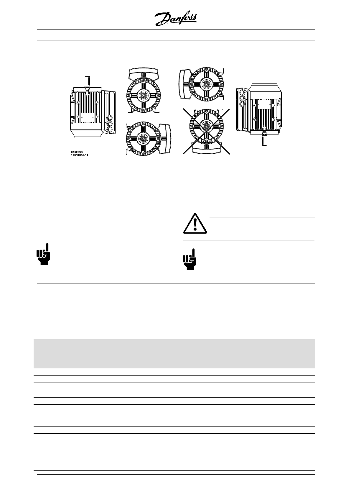
All operations must be carried out by
appropriately trained personel.
Use all lifting facilities provided
e.g. both lifting points if fitted or
single lifting point if fitted*.
Vertical lifting - Prevent uncontrolled rotation.
Lift machine - Do not lift other equipment with
motor lifting points only.
Before installation check for fan cover damage,
shaft damage, foot/mounting damage, and loose
fasteners. Check nameplate details.
Ensure level mounting surface, balanced
mounting, not misaligned.
Gaskets, and/or sealants, and guards must
be correctly fitted.
Correct belt tension.
Please observe derating rules, see "Special conditions".
*Note: maximum hand lift is 20 kg below shoulder,
but above ground level. Max. gross weights:
- Frame size 80: 15 kg
- Frame size 90 & 100: 30 kg
- Frame size 112: 45 kg
- Frame size 132: 80 kg
2. Correct protective earthing of the equipment
must be established, the user must be protected
against supply voltage, and the motor must be
protected against overload in accordance with
applicable national and local regulations.
Use of RCD’s(ELCBrelays)isdescribed
in chapter 10.
3. The earth leakage currents are higher than 3.5
mA. This means that the FC motor requires
a fixed, permanent installation as well as
reinforced protective earthing.
■ Warning against unintended start
1. The motor can be brought to a stop by means of
digital commands, bus commands, or references,
while the frequency converter is connected to mains.
If personal safety considerations make it necessary
to ensure that no unintended start occurs, t
stop functions are not sufficient .
2. While parameters are being changed, the
motor may start.
3. A motor that has been stopped may start
if faults occur in the electronics of the FC
motor, or if a temporary overload or a fault
in the mains supply ceases.
hese
The voltage on the FC motor is
dangerous when the motor is connected
to mains. Incorrect installation of
the FC motor may lead to material damage or
serious injury, or it may be fatal.
Consequently, the instructions in this manual
as well as national and local rules and safety
regulations must be complied with.
Touching the electrical parts may be fatal, even
after the mains supply has been disconnected.
Wait at least 4 minutes.
- Installation must be fused and isolated correctly.
- Covers and cable entries must be fitted.
NB!:
It is the user’s or certified electrician’s
responsibility to ensure correct earthing and
protection in accordance with applicable
national and local requirements and standards.
■ Safety regulations
1. The VLT DriveMotor (FC motor) must be
disconnected from mains if repair work
is to be carried out.
Check that the mains supply has been disconnected
and that the necessary time has passed (4 minutes).
4
MG.03.H3.02 - VLT is a registered Danfoss trademark
Page 5
VLT®FCM Series
■Introduction
Specific technical publications on the FCM 300 series:
Design Guide: Gives all required information for design purposes, and gives a good
insight into the product concept, product range, technical data, control,
programming, etc.
Quick Setup: Helps the users to quickly get their FCM 300 Series motor unit installed
and running.
The Quick Setup is always delivered with the unit.
If you have a
ny questions concerning FCM 300
Series, please call us. We have drive specialists all
over the world ready to advise you on applications,
mming, training and service.
progra
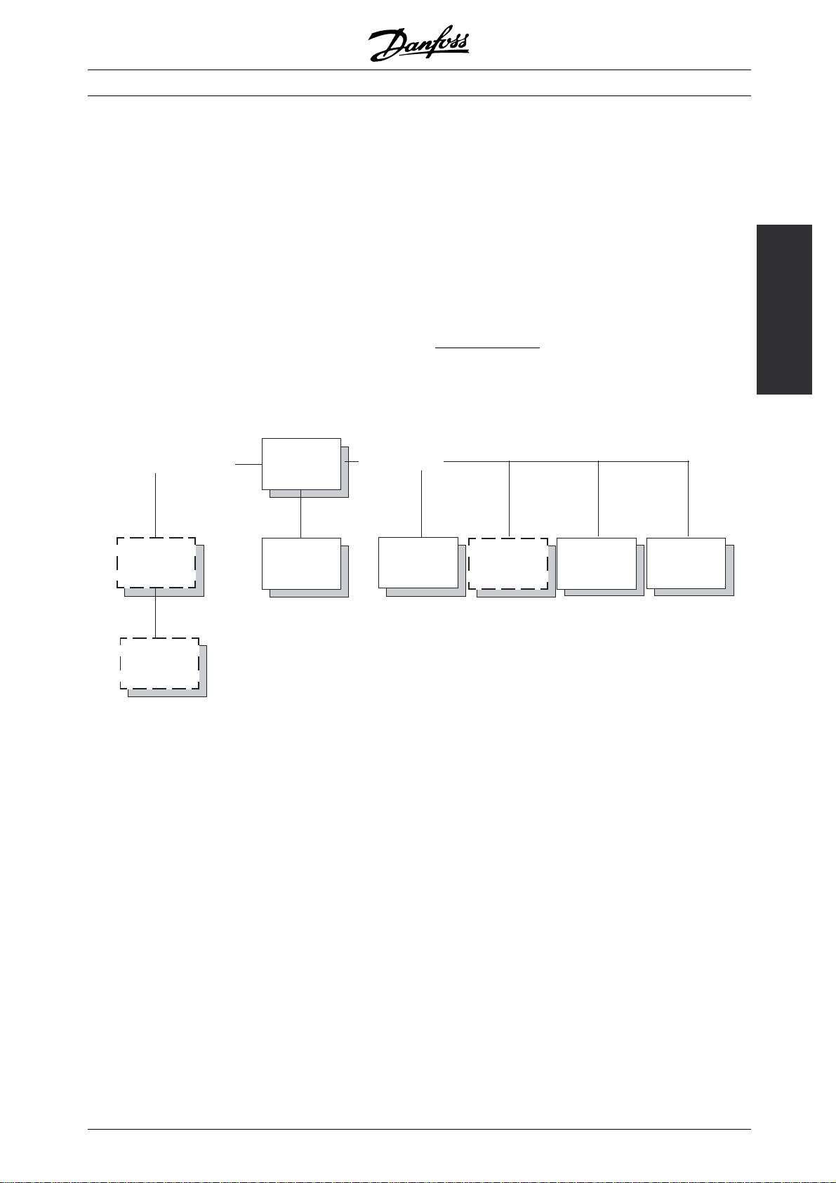
Promotion
Brochure
MB.03.CX.YY
Articles
MZ.03.AX.YY
All
users
Quick Setup
MG.03.FX.YY
A
The chart below gives an overview of the literature
available for the FCM 300 Series.
Misc.
Design
Guide
MG.03.BX.YY
vailable literature
VLT Software
Dialog
MG.50.EX.YY
PROFIBUS-
Manual
MG.03.EX.YY
X = version number
YY = language
Introduction
175NA116.10
Data sheet
MD.03.AX.YY
MG.03.H3.02 - VLT is a registered Danfoss trademark
5
Page 6
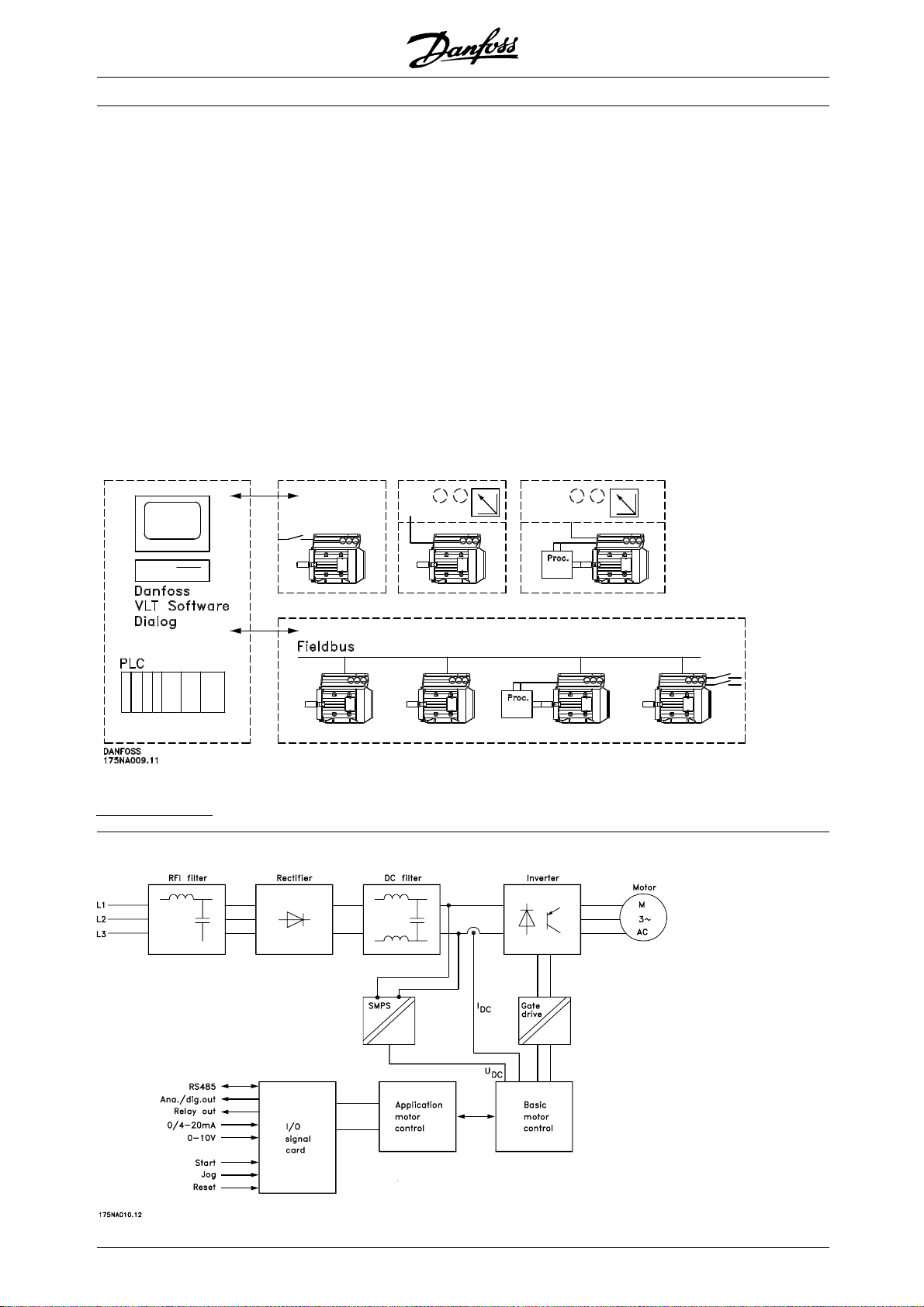
■ Integration of frequency converter and motor
The Danfoss VLT frequency converter integrated
onto the asynchronous motor gives infinite
speed control in one unit.
The VLT DriveMotor FCM 300 Series is a very compact
alternative to the ordinary solution with VLT frequency
converter and motor as separate units. The frequency
converter is attached instead of the motor terminal box,
and it is no higher than the standard terminal box, nor
widerorlongerthanthemotor(seechapter6).
Installation is made extremely easy. Panel space is
not a problem. There is no need for special details
on wiring to meet the EMC directive, since motor
cables are not necessary. The only connections
are mains and control connections.
VLT®FCM Series
Factory-set adaption between frequency converter
and motor gives precise and energy efficient control
in addition to eliminating pre-setting on site.
The FC motor can be used in stand alone systems
with traditional control signals, such as start/stop
signals, speed references and closed loop process
control or in multiple drive systems with control
signals distributed by a field bus.
Combination of fieldbus and traditional control signals
and closed loop PID control is possible.
Control structures
■ Key diagram for FCM 3
00 Series
6
MG.03.H3.02 - VLT is a registered Danfoss trademark
Page 7

VLT®FCM Series
■ Product range
LT DriveMotor FCM 300 Series, 2/4 poled motors
V
Type Motor output Mains supply
FCM 305 0.55 kW
FCM 307 0.75 kW
FCM 311 1.1 kW
FCM 315 1.5 kW
FCM 322 2.2 kW
3 phase 380-480 V
FCM 330 3.0 kW
FCM 340 4.0 kW
FCM 355 5.5 kW
FCM 375 7.5 kW
Each type in the product range is available
in different versions:
nverter versions
I
Drive control:
- F 00: Without Fieldbus
- F 10: With PROFIBUS DP 3 MBit/s
- F 12: With PROFIBUS DP 12MBit/s
RFI filter:
Inverter with integrated RFI filter, class 1A (industrial)
or class 1B (domestic).
Cooling:
- TEFV: Motor cooled by a shaft mounted fan (IC 411)
ounting versions
M
- Foot mounting (B3)
- Flange mounting (B5)
- Face mounting (B14)
- Foot + flange mounting (B35)
- Foot + face mounting (B34)
See section Dimensions.
anfoss PC software for serial communication, MCT 10
D
All FCM 300 Series units have an RS 485 port as
standard, which enables them to communicate e.g.
with a PC. A programme entitled MCT 10 is available
for this purpose (see section PC Software tools).
rdering numbers, MCT 10
O
Please order your CD containing MCT 10 Set-up
Software using code number 130B1000.
C Software - VLT Software Dialog
P
For single or few unit installations a basic software
package, VLT Software Dialog, is available. Please
order using code number 175Z0967.
ccessories for the FC motor
A
A Local Operation Pad (LOP) for local set point and
start/stop is available for the FC motor. The LOP is IP 66
enclosed. A Local Control Panel (LCP 2) which makes
up a complete interface for operation, programming
and monitoring of the FC motor is also available.
rdering numbers, accessories
O
Local Operation Pad (LOP) 175N0128
Local Control Panel (LCP 2) 175N0131
Remote mounting kit (LCP 2) 175N0160
Plug kit (LCP 2) 175N2545
Cable for plug kit (LCP 2) 175N0162
Cable (direct mounting) (LCP 2) 175N0165
Service plug kit (LCP 2) 175N2546
Potentiometer option
177N0011
(Available from February 2005)
Introduction
nverter box position: Top, opposite motor feet.
I
D
rainhole (+ position): None, D1, D2, D3 (see
drawing in section Ordering info for inverter box
position and drain hole position.
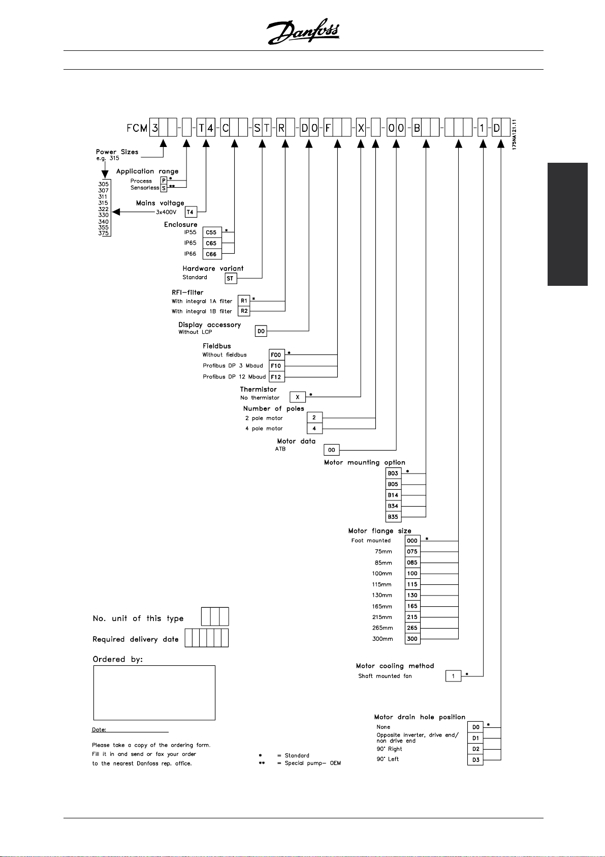
■ Ordering
Take a copy of the ordering form, see section
Ordering form. Fill in and post or fax your order
to the nearest branch office of the Danfoss sales
organisation. On the basis of your order, the FCM
300 Series motor is given a type code.
The ordering form for the basic unit must always be
completed. When the type code is written, always
state the characters of the basic string (1-34). Together
with the order confirmation the customer receives an
8-figure code number to be used when reordering.
MG.03.H3.02 - VLT is a registered Danfoss trademark
7
Page 8
■Ordering info for Frames and Flanges
Frame sizes and the corresponding flange sizes
for different mounting versions
VLT®FCM Series
Type Motor frame size Mounting version Flange size, standard
(S) [mm]
FCM 305 80
FCM 307 80
FCM 311 90
FCM 315 90
FCM 322 100
FCM 330 100
FCM 340 112
FCM 355 132
FCM 375 132
B5/B35 165 100/115/130/215
B14/B34 100 85/115/130
B5/B35 165 100/115/130/215
B14/B34 100 85/115/130
B5/B35 165 130/215
B14/B34 115 100/130
B5/B35 165 130/215
B14/B34 115 100/130
B5/B35 215 165/265
B14/B34 130 115/165
B5/B35 215 165/265
B14/B34 130 115/165
B5/B35 215 165/265
B14/B34 130 165
B5/B35 265 215/300
B14/B34 165 130
B5/B35 265 215/300
B14/B34 165 130
Flange size according to IEC ref. FFxxx (Dimension M), see section Dimensions
S: Available as standard shaft
*
No changes regarding shaft dimensions
Flange size,
alternatives
*
[mm]
■Ordering info for inverter box position a
drain hole position
Inverter box position, always top mounted.
D1: Drain holes opposite inverter side, both
drive end and non drive end.
D2/D3: Drain holes 90° to inverter, both drive
end and non drive end.
nd
All drain holes are mounted with screw and
washer, IP 66 if not opened.
8
MG.03.H3.02 - VLT is a registered Danfoss trademark
Page 9
■Ordering form
VLT®FCM Series
Introduction
MG.03.H3.02 - VLT is a registered Danfoss trademark
9
Page 10

VLT®FCM Series
■ FCM 305-375 for 3 phases, 380-480 V
FCM 305 307 311 315 322 330 340 355 375
Motor output
[HP] 0.75 1.0 1.5 2.0 3.0 4.0 5.0 7.5 10.0
[kW] 0.55 0.75 1.1 1.5 2.2 3.0 4.0 5.5 7.5
Motor torque
2pole[Nm]
4pole[Nm]
Frame
size [mm] 80 80 90 90 100 100 112 132 132
Weight [kg] 11 13 17 20 26 28 37 56 61
Input current [A]
380 V
2 p 1.5 1.8 2.3 3.4 4.5 5.0 8.0 12.0 15.0
4 p 1.4 1.7 2.5 3.3 4.7 6.4 8.0 11.0 15.5
480 V
2 p 1.2 1.4 1.8 2.7 3.6 4.0 6.3 9.5 11.9
4 p 1.1 1.3 2.0 2.6 3.7 5.1 6.3 8.7 12.3
Efficiency at
nom. speed
(4 pole) % 66 71 74 80 80 81 80 84 84
Efficiency at
nom. speed
(2 pole) % 61 64 76 75 76 85 82 83 91
Power terminals
[AWG] 10101010101010 6 6
[mm2] 4 4 4 4 4 4 4 10 10
Gland sizes 3xM20x1.5 3xM20x1.5 3xM20x1.5 3xM20x1.5 3xM20x1.5 3xM20x1.5 3xM20x1.5 1xM25x1.5/
Max. prefuse
UL
IEC
At 400 V 3000 r/min
1)
At 400 V 1500 r/min
2)
Type gG prefuses must be used. If you want to maintain UL/cUL you must use prefuses of the type Bussmann KTS-R 500 V or Ferraz
3)
Shawmut, ATMR Class C (max. 30A). The fuses must be placed for protection in a circuit that is capable of supplying a maximum of
100,000 amps RMS (symmetrical), 500 V maximum.
1)
2)
3)
[A] 101010101015152525
3)
[A] 252525252525252525
1.8 2.4 3.5 4.8 7.0 9.5 12.6 17.5 24.0
3.5 4.8 7.0 9.6 14.0 19.1 25.4 35.0 48.0
1xM25x1.5/
2xM20x1.5
2xM20x1.5
■General technical data
Mains supply, TT, TN and IT* (L1, L2, L3):
- Supply voltage 380-480 V units .............................................................. 3 x 380/400/415/440/460/480 V ±10%
- Supply frequency ................................................................................................................................... 50/60 Hz
- Max. imbalance of supply voltage ............................................................................ ±2% of
rated supply voltage
- Power factor / cos φ .................................................................................................... max. 0.9/1.0 at rated load
- No. of switching operations on supply input L1, L2, L3 ....................................................... approx. 1 time/2 min
*) Not valid for RFI class 1B units
Torque characteristics:
- Starting torque/overload torque ................................................................................................... 160 % fo
- Continuous torque ................................................................................................................................ see above
Control card, digital/pulse inputs:
- Number of programmable digital inputs .............................................................................................................. 4
10
MG.03.H3.02 - VLT is a registered Danfoss trademark
r1min
Page 11

VLT®FCM Series
- Terminal nos. ............................................................................................................................ X101-2, -3, -4, -5
- Voltage level ........................................................................................................ 0-24 V DC (PNP positive logics)
- Voltage level, logic
- Voltage level, logic
- Maximum voltage on input ..................................................................................................................... 28 V DC
- Input resistance, R
- Scanning time ........................................................................................................................................ 20 msec
Control card, pulse input:
- No. of programmable pulse inputs ..................................................................................................................... 1
- Terminal nos. ............................................................................................................................................ X101-3
- Max. frequency on terminal 3, open collector/push pull 24 V .......................................................... 8 kHz/70 kHz
- Resolution ................................................................................................................................................... 10 bit
- Accuracy (0.1-1 kHz), terminal 3 .............................................................................. Max. error: 0.5% of full scale
- Accuracy (1-12 kHz), terminal 3 ............................................................................... Max. error: 0.1% of full scale
Control card, analogue inputs:
- No. of programmable analogue voltage inputs .................................................................................................. 1
- Terminal nos. ........................................................................................................................................... X101-2
- Voltage level ....................................................................................................................... 0 - 10 V DC (scalable)
- Input resistance, R
- No. of programmable analogue current inputs ................................................................................................... 1
- Terminal no. .............................................................................................................................................. X101-1
- Current range ........................................................................................................................ 0 - 20 mA (scalable)
- Input resistance, R
- Resolution ..................................................................................................................................................... 9 bit
- Accuracy on input ....................................................................................................... Max. error 1% of full scale
- Scanning time ....................................................................................................................................... 20 msec.
´
0 .............................................................................................................................. <5VDC
´
´
1 ............................................................................................................................ > 10VDC
´
............................................................................................................................... approx. 2
i
............................................................................................................................. approx. 10
i
............................................................................................................................. approx. 30
i
Installation
Control card, digital/pulse and analogue outputs:
- No. of programmable digital and analogue outputs ........................................................................................... 1
- Terminal nos. ............................................................................................................................................ X101-9
- Voltage level at digital output/load .......................................................................................... 0 - 24 VDC/25mA
- Current at analoque output ................................................................................................................... 0 - 20 mA
- Maximum load to frame (terminal 8) at analogue output ................................................................ R
LOAD
≤ 500
- Accuracy of analogue output ................................................................................... Max. error: 1.5% of full scale
- Resolution on analogue output. ..................................................................................................................... 8 bit
Relay output:
- No. of programmable outputs ............................................................................................................................ 1
- Terminal nos. .............................................................................................. 1-2 (make), 1-3 (brake) terminal X102
- Voltage level at contact/load (AC) ...................................................................................... 250 V AC, 5A-AC load
- Voltage level at contact/load (DC) ..................................................... 30 V DC, 5A; 40 V DC, 2A; 100 V DC, 0.5A
Control card, RS 485 serial communication:
- Terminal nos. ....................................................................................................................................... X100-1, -2
Control characteristics (frequency converter):
- Frequency range ................................................................................................................................. 0 - 132 Hz
Please see special conditions for frequency range for IP 66 motors at the end of this section.
- Resolution on output frequency .................................................................................................................. 0.1 %
- System response time .................................................................................................................. Max. 40 msec.
- Speed accuracy (open loop, CT mode, 4 P motor driven in speed range 150-1500 rPm) .................... +/- 15 rpm
MG.03.H3.02 - VLT is a registered Danfoss trademark
11
Page 12
VLT®FCM Series
Externals:
- Enclosure .................................................................................................................................. IP 55 (IP56, IP66)
Please see special conditions for frequency range for IP 66 motors at the end of this section.
- Vibration test ................................................................................................................. (IEC68seepage93)1g
- Max. relative humidity .............................................................. 95 % (IEC 68-2-3) for storage/transport/operation
- Ambient temperature ............................................................................ Max. 40°C (24-hour average max. 35°C)
see Derating for high ambient temperature
- Min. ambient temperature in full operation ..................................................................................................... 0°C
- Min. ambient temperature at reduced performance ................................................................................... -10°C
- Temperature during storage/transport .......................................................................................... -25 - +65/70°C
- Max. altitude above sea level .................................................................................................................... 1000 m
see Derating for air pressure
- EMC standards applied, Emission ................... EN 61000-6-3/EN 6100-6-4, EN 61800-3, EN 55011, EN 55014
- EMC standards applied, Immunity ................................................................................................................... EN
61000-6-2, EN 61000-4-2, EN 61000-4-3, EN 61000-4-4, EN 61000-4-5, EN 61000-4-6, ENV 50204
- Safety standards applied, ..................................................................... EN 60146, EN 50178, EN 60204, UL508
NB!:
Please note that the normal IP 66 solution
is only intended for speed up to maximum
3000 rpm. If higher speed is needed, please
give notification when ordering.
Protection:
• Thermal overload protection of motor
and electronics.
• Monitoring of the intermediate circuit voltage
ensures that the inverter cuts out if the intermediate
circuit voltage gets too high or too low.
• If a mains phase is missing, the inverter will cut
out when a load is placed on the motor.
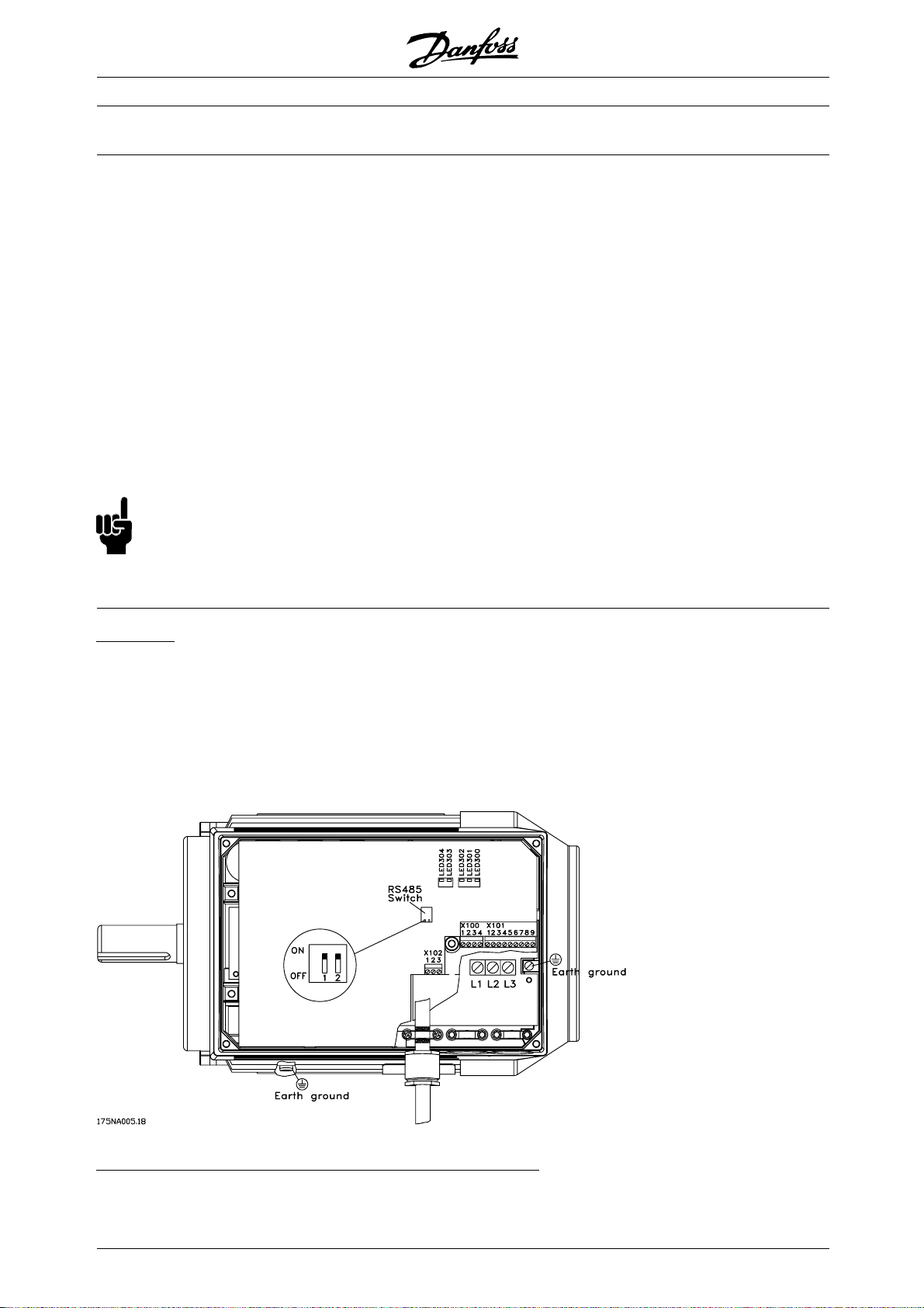
Terminal arrangement (for installation see quick setup, MG.03.AX.62)
12
MG.03.H3.02 - VLT is a registered Danfoss trademark
Page 13
VLT®FCM Series
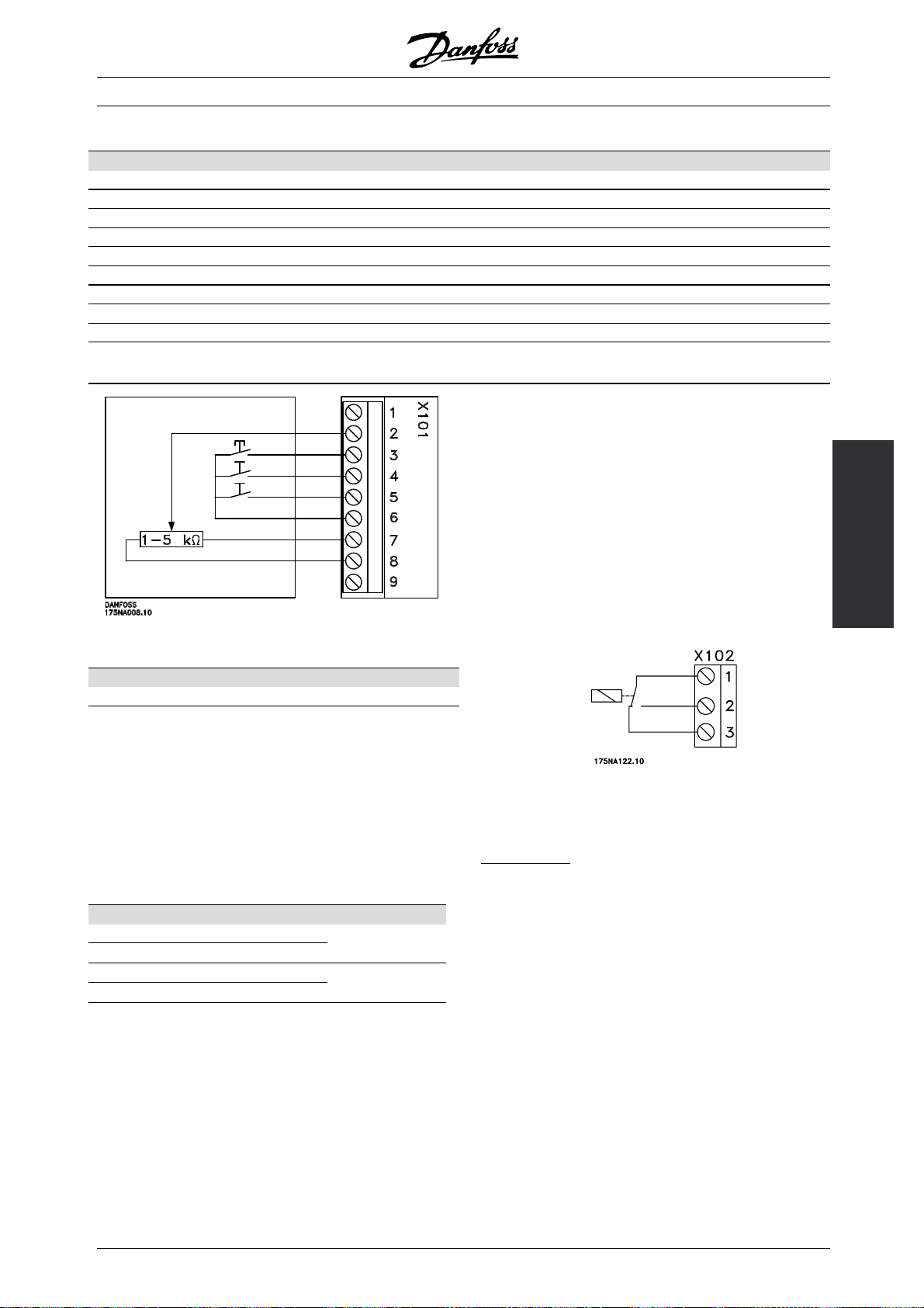
X101: Terminal block for analogue/digital control signals
Terminal No. Function Example
1 Analogue input (0-20 mA) Feedback signal
2 Analogue (0-10 V)/digital input 2 Speed reference
3 Digital input (or pulse) 3 Reset
4 Digital input (or precise stop) 4 Start
5 Digital input (other) 5 Jog (fixed speed)
6 24 V DC supply for digital inputs (max. 150 mA)
7 10 V DC supply for potentiometer (max. 15 mA)
80Vforterminals1-7and9
9 Analogue (0-20 mA)/digital output Fault indication
Connection diagram - factory setting
- Reset to be closed short time for resetting fault trips
- Start to be closed for changing to run mode
- Jog will run at fixed speed while closed (10 Hz)
- Speed reference (0-10 V) determines speed
while in run mode
X102: Terminal block for relay output
Terminal No. Function
1-2 Make (normally open)
1-3 Brake (normally closed)
See parameter 323 (relay output) for programming
of relay output.
X100: Terminal block for data communication
Terminal No. Function
1PRS485
2 N RS 485
35VDC
40VDC
for connection
to bus or PC
Supply for RS
485 bus
Installation
LED 300-304
LED 300 (red): Fault trip
LED 301 (yellow): Warning
LED 302 (green): Power on
LED 303-304: Communication
For PROFIBUS versions please refer to the
manual MG.90.AX.YY.
MG.03.H3.02 - VLT is a registered Danfoss trademark
13
Page 14

VLT®FCM Series
■Tightening Torques
Cover (lid) screws: 19.5 - 21.2 lb-in (2.2 - 2.4 Nm)
Plastic cable entrance plugs: 19.5 lb-in (2.2 Nm)
L1, L2, L3 (AC Line) screws (FCM 305-340): 5 - 7 lb-in (0.5 - 0.6 Nm)
L1, L2, L3 (AC Line) screws (FCM 355-375): 15 lb-in (1.2 - 1.5 Nm)
Earth Ground: 30.1 lb-in (3.4 Nm)
Terminal screws require a max 2.5 mm
flat-blade screwdriver.
AC Line screws require a 8mm flat-blade screwdriver.
■Maximum Cable Cross Section
Earth ground and cable clamp screws all require
T-20 Torx or flat-blade screwdriver.
Lid screws require Philips screwdriver.
Note:
Use°60Ccopperwireorbetter
AWG mm
Max size AC Line cable (FCM 305-340): 10 4.0
Max size AC Line cable (FCM 355-375): 6 10
Max size control cable: 16 1.5
Max size serial communication cable: 16 1.5
Earth Ground: 6 10
■Screw Sizes
Cover (lid) screws: M5
Earth Ground and Cable Clamp screws (FCM 305-340): M4
Earth Ground and Cable Clamp screws (FCM 355-375): M5
2
14
MG.03.H3.02 - VLT is a registered Danfoss trademark
Page 15
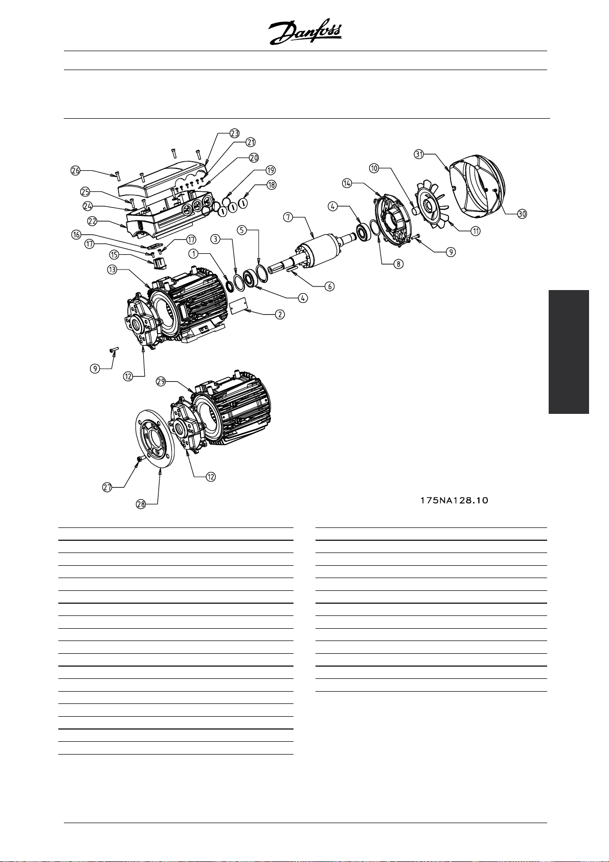
■Description of the motor
The FC motor consists of the following parts:
VLT®FCM Series
Item Description Item Description
1 Gasket 19 Gaskets for cable glands
2 Name plate 20 Cable Clamps
3 Shim ring 21 Screws for cable clamps
4 Ball bearing 22 Frequency inverter
5 Circlip for drive-end bearing 23 Lid for frequency inverter
6 Key 24 Gasket
7 Rotor 25 Torx-screws for inverter monting
8 Shim ring for bearing 26 Screws for lid
9 Tension screws 27 Mounting screws for flange ring
10 Tolerance ring for air blower 28 Flange ring
11 Air blower 29 Stator
12 Endshield drive end 30 Mounting screws for air blower hood
13 Stator 31 Air blower hood
14 Endshield non drive end
15 Connector block
16 Gasket
17 Screws for connector block
18 Metric blind plugs
Installation
MG.03.H3.02 - VLT is a registered Danfoss trademark
15
Page 16

VLT®FCM Series
■ Handling the FC motor
Handling and lifting of VLT DriveMotors (FC motors)
must only be undertaken by qualified personnel. Full
product documentation and operating instructions
must be available together with tools and equipment
necessary for safe working practice. Eyebolts and/or
lifting trunnions supplied with the FC motor are
designed to support only the weight of the FC motor,
not the weight of the FC motor and any auxcillary
equipment attached to it. Be absolutely sure that
cranes, jacks, slings and lifting beams are capable of
carrying the weight of equipment to be lifted. Where
an eyebolt is provided with the motor, this should
■ Bearings
The standard solution is fixed bearing in the drive
side of the motor (shaft output side).
To avoid static indention, the storage area should be
vibration free. Where exposure to some vibration is
unavoidable, the shaft should be locked. Bearings
may be fitted with a shaft locking device which should
be screwed down until its shoulder is firmly against
the face of the stator frame to be lifted.
FCM type approx. weight (kg.)
FCM 305 11
FCM 307 13
FCM 307 17
FCM 315 20
FCM 322 26
FCM 330 28
FCM 340 37
FCM 355 56
FCM 375 61
be kept in place during storage. Shafts should be
rotated by hand, one quarter of a revolution, at weekly
intervals. Bearings are despatched from the works
fully charged with lithium based grease.
Lubrication
Frame size Lubrication type Temperatur range
80-132 Esso unirex N3 -10 to + 1400°C
Bearing life
Maximum hours bearing life (Lna) expected at 80° C bearing temp. x 103hours.
FCM 3000 min
-1
1500 min
-1
Horiz. Vert. Horiz. Vert.
305-315 22 22 30 30
322-340 26 26 30 30
355-375 26 26 30 30
Lna bearing life is the adjusted, L10 life rating, taking account of: -Reliability -Material improvement -Lubrication
conditions.
Standard Bearing references and oil seals
FCM Mounting Poles (2/4) Bearings Oil seals - Bore x O/D x width in mm
Drive end Non-drive end
305-307 All All 6204 2Z-C3 6204 2RS-C3 20 x 30 x 7
311-315 All All 6205 2Z-C3 6205 2RS-C3 25 x 35 x 7
322-330 All All 6206 2Z-C3 6206 2RS-C3 30 x 42 x 7
340 All All 6206 2Z-C3 6206 2RS-C3 30 x 42 x 7
355-375 All All 6208 2Z-C3 6208 2RS-C3 40 x 52 x 7
■ Output shafts
Output shafts are produced from 35/40 Ton (460/540
2
) tensile steel. Drive end shafts are provided
MN/m
with a tapped hole to DIN 332 Form D and a
closed profile keyway as standard.
alance
B
All motors are dynamically balanced, to ISO 8821with
key convention to IEC 60034-14.
16
MG.03.H3.02 - VLT is a registered Danfoss trademark
Page 17
Inertia
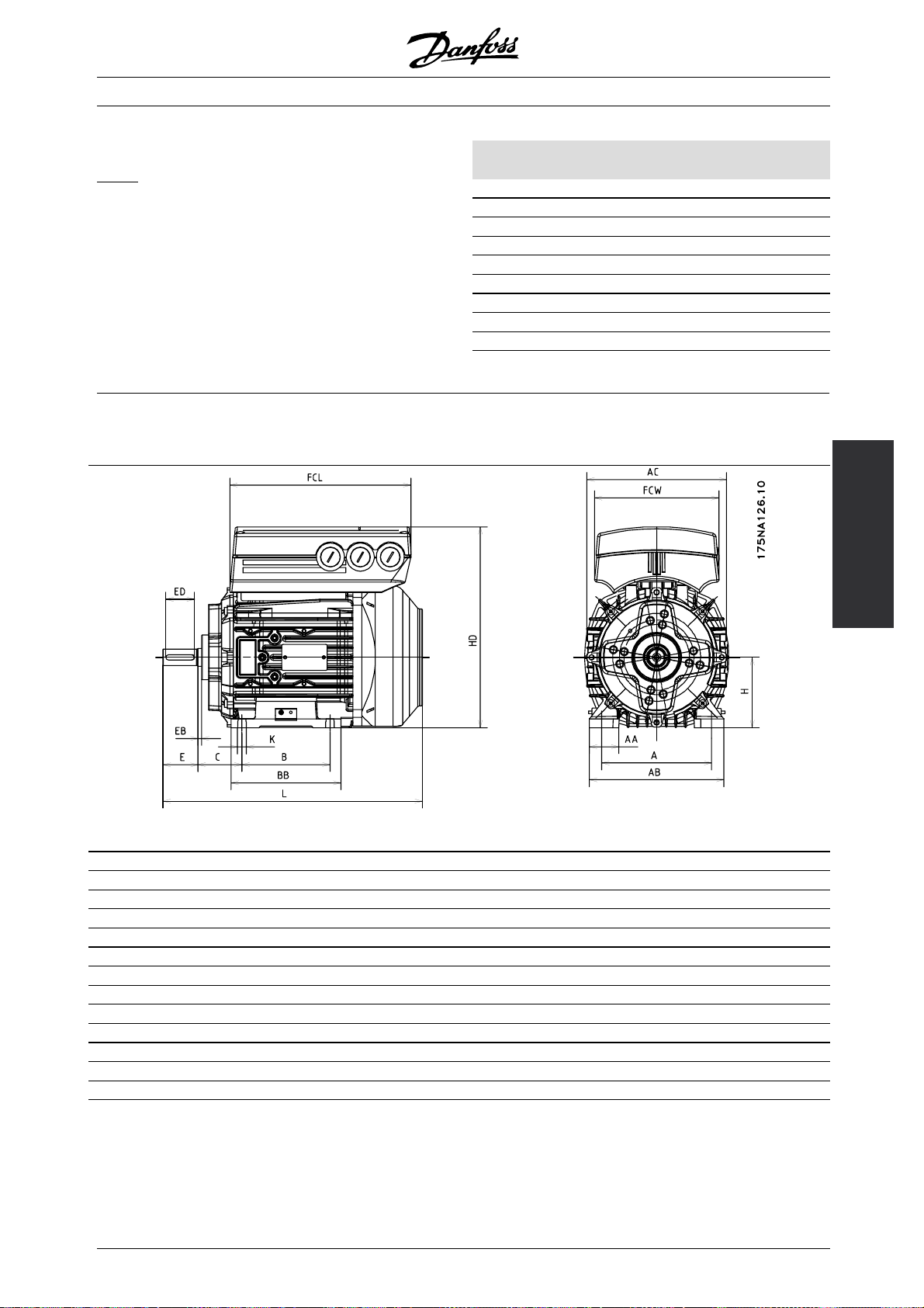
■ Dimensions
Foot mounting - B3
VLT®FCM Series
FCM J [kgm2]
2pole 4pole
305 0.0015 0.0019
307 0.0015 0.0027
311 0.0024 0.0022
315 0.0012 0.0030
322 0.006 0.0042
330 0.0028 0.0050
340 0.0053 0.0091
355 0.0074 0.0143
375 0.0097 0.0190
General
FCM 305 307 311 315 322 330 340 355 375
Frame size 80 80 90 90 100 100 112 132 132
A [mm] 125 125 140 140 160 160 190 216 216
B [mm] 100 100 125 125 140 140 140 178 178
C[mm]505056566363708989
H [mm] 80 80 90 90 100 100 112 132 132
K[mm]99991212121212
AA [mm] 33.5 33.5 35 35 38 38 44 55 55
AB [mm] 153 153 170 170 195 195 225 256 256
BB [mm] 125 125 155 155 176 176 176 218 218
L [mm] 295 295 319 319 336 336 380 485 485
AC [mm] 159 159 176 176 196 196 220 246 246
HD [mm] 228.5 228.5 241 241 267 267 296 344 344
FCL [mm] 206 206 230 230 256 256 286 340 340
FCW [mm] 141 141 158 158 176 176 197 235 235
Installation
MG.03.H3.02 - VLT is a registered Danfoss trademark
17
Page 18
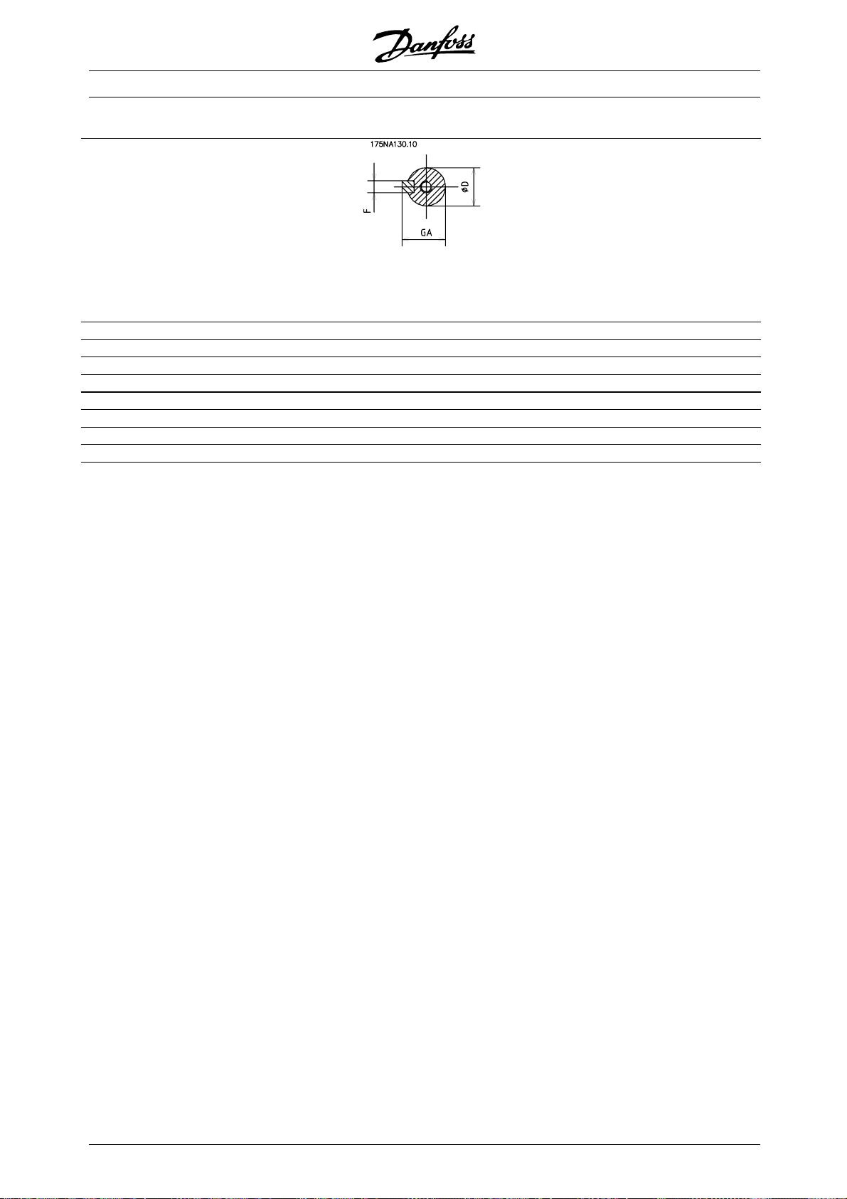
VLT®FCM Series
Shaft Drive End
Shaft tapped
DH x deep to
DIN 332 Form DR
FCM 305 307 311 315 322 330 340 355 375
Frame size 80 80 90 90 100 100 112 132 132
D [mm] 19 19 24 24 28 28 28 38 38
E [mm] 40 40 50 50 60 60 60 80 80
ED [mm] 32 32 40 40 50 50 50 70 70
EB[mm]445555555
DH [mm] M6x16 M6x16 M8x19 M8x19 M10x22 M10x22 M10x22 M12x28 M12x28
F[mm]66888881010
GA [mm] 21.5 21.5 27 27 31 31 31 41 41
18
MG.03.H3.02 - VLT is a registered Danfoss trademark
Page 19
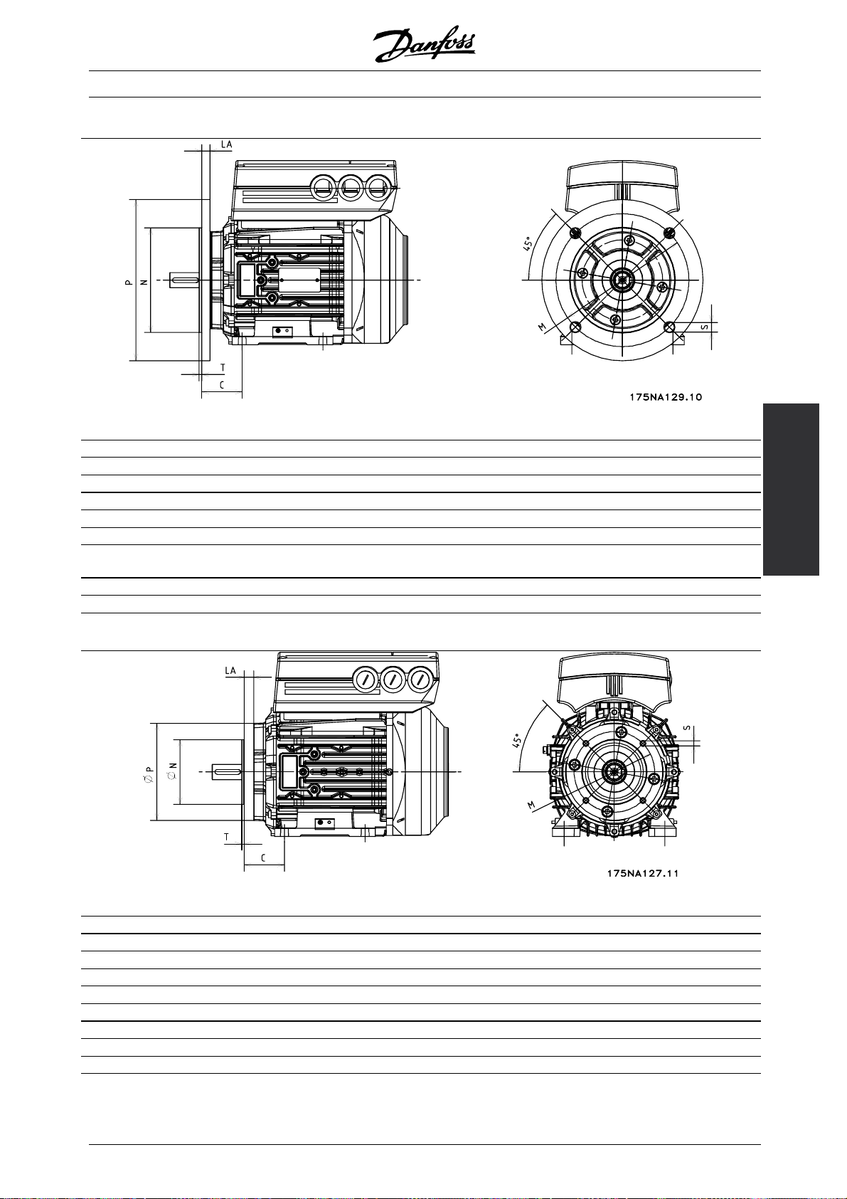
VLT®FCM Series
Flange mounting - B5, B35 (B3+B5)
B5
FCM 305 307 311 315 322 330 340 355 375
Framesize80809090100100112132132
IEC Ref. FF165 FF165 FF165 FF165 FF215 FF215 FF215 FF265 FF265
DIN Ref. A200 A200 A200 A200 A250 A250 A250 A300 A300
M [mm] 165 165 165 165 215 215 215 265 265
N [mm] 130 130 130 130 180 180 180 250 230
P [mm] 200 200 200 200 250 250 250 300 300
S[mm] 121211.511.51414141414
Installation
T[mm]3.53.53.53.544444
LA [mm] 10 10 10 10 11 11 11 12 12
Face mounting - B14, B34 (B3+B14)
B14
FCM 305 307 311 315 322 330 340 355 375
Frame size 80 80 90 90 100 100 112 132 132
IEC Ref. FT100 FT100 FT115 FT115 FT130 FT130 FT130 FT165 FT165
DIN Ref. C120 C120 C140 C140 C160 C160 C160 C200 C200
M [mm] 100 100 115 115 130 130 130 165 165
N [mm] 80 80 95 95 110 110 110 130 130
P [mm] 120 120 140 140 160 160 160 200 200
S [mm] M6 M6 M8 M8 M8 M8 M8 M10 M10
T [mm] 3 3 3 3 3.5 3.5 3.5 3.5 3.5
LA [mm] 12 12 10 10 10 10 10 12 12
MG.03.H3.02 - VLT is a registered Danfoss trademark
19
Page 20
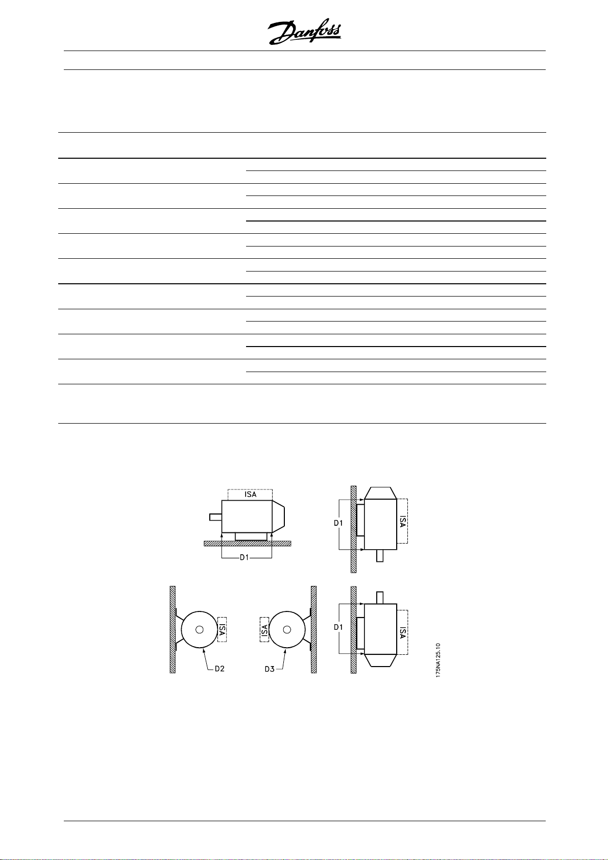
■ Installation of the FC motor
FC motors must be installed with adequate access for
routine maintenance. A minimum of 0.75m of working
space around the motor is recommended. Adequate
space around the motor, particularly at the fan inlet
(50 mm), is also necessary to facilitate airflow.
Where several FC motors are installed in close
proximity, care must be taken to ensure that there is
no recirculation of exhausted warm air. Foundations
must be solid, rigid and level.
NB!:
Electrical installation
Do not remove the top foil inside the inverter part,
as this is a part of the protective arrangements.
VLT®FCM Series
itting pinions, pulleys and couplings.
F
These should be bored to our standard limits and fitted
on the shaft with a screwing motion. Attention must
be paid to correct guarding of all moving parts.
Tapping of fitments onto the FC motor shaft,
with a hammer or mallet, causes bearing
damage. This results in an increase in
bearing noise and a significant reduction in bearing life.
NB!:
Max. length of mounting bolts penetrating
the B14 flange, see section Dimensions
in this chapter.
■ Alignment
When the application calls for direct coupling, the
shafts must be correctly aligned in all three planes. Bad
alignment can be a major source of noise and vibration.
Maximum permissible external axial and radial loads in N
Allowance must be made for shaft endfloat and
thermal expansion in both axial and vertical planes.
It is preferable to use flexible drive couplings.
1
- standard ball bearings
Horizontal shaft Vertical shaft
Load towards Load away Shaft up Shaft down
Frame motor from motor load load load load
size Poles Up Down Up Down Max. radial
80 2 275 441 481 245 294 432 638
4 373 549 569 343 392 520 785
90 2 412 638 598 294 373 520 824
4 540 765 716 402 471 628 903
100 2 853 853 932 932 814 814 1207
4 1010 1010 1118 1118 961 961 1393
112 2 853 853 932 932 814 814 1207
4 1010 1010 1118 1118 961 961 1393
132S 2 1059 1403 1570 952 1216 1305 1785
4 1265 1609 1825 1138 1472 1481 1972
132M 4 1256 1609 1854 1109 1501 1462 2040
1
All figures are based on Lna bearing life of 20,000 hours.
Lna = adjusted L10 life rating taking account of:-Reliability -Material improvements -Lubrication conditions
2
Max. permissible radial load at end of shaft (horizontal mounting).
2
20
MG.03.H3.02 - VLT is a registered Danfoss trademark
Page 21
VLT®FCM Series
Maximum permissible external axial and radial loads in N1- reinforced ball bearings
Horizontal shaft Vertical shaft
Load towards Load away Shaft up Shaft down
Frame motor from motor load load load load
size Poles Up Down Up Down Max. radial
80 2 1375 2205 2405 1225 1470 2160 3190
4 1865 2745 2845 1715 1960 2600 3925
90 2 2060 3190 2990 1470 1865 2600 4120
4 2700 3825 3580 2010 2355 3140 4515
100 2 4265 4265 4660 4660 4070 4070 6035
4 5050 5050 5590 5590 4805 4805 6965
112 2 4265 4265 4660 4660 4070 4070 6035
4 5050 5050 5590 5590 4805 4805 6965
132S 2 5295 7015 7850 4760 6080 6525 8925
4 6325 8045 9125 5690 7360 7405 9860
132M 4 6280 8045 9270 5545 7505 7310 10200
1
All figures are based on Lna bearing life of 20,000 hours.
Lna = adjusted L10 life rating taking account of:-Reliability -Material improvements -Lubrication conditions
2
Max. permissible radial load at end of shaft (horizontal mounting).
2
■ Bolt torques
Endshields and lid should be secured with the bolt
sizes and torque’s detailed in the table below.
Endshield fixing bolt torques
FCM Type Frame size Bolt diameter Torque
Nm.
305-307 80 M5 5
311-315 90 M5 5
322-330 100 M6 (taptite) 8-10
340 112 M6 (taptite) 8-10
355-375 132 M8 (taptite) 29
LID screws torque: 2.2 - 2.4 Nm
■Maintenance
outine cleaning of the FC motor
R
Remove the fan cover and ensure that all air inlet holes
are completely free. Clean any dirt and obstructions
from behind the fan and along the ribs of the frame,
and between the motor and inverter part.
eriodic maintenance of motor part.
P
a. Remove the inverter part, the fan cover and
the fan which is keyed to the shaft extension.
Loosen and remove bearing cover screws and
endshield bolts/studs.The endshields should
then be eased off their spigots.
b. The rotor can now be carefully withdrawn from
the stator, taking care not to damage the stator
bore and both stator and rotor windings.
c. Having dismantled the motor, maintenance can be
carried out to remove all dirt. For this purpose,
the use of an air line supplying dry compressed
air under comparatively low pressure is best, as
a high velocity air-stream can force dirt into the
spaces between the windings and insulation, etc.
Grease-removing solvents can cause damage
to impregnating varnish or insulation
d. The FC-motor should be re-assembled in the
reverse order from dismantling, remember
to ease endshields onto bearings and spigots.
DO NOT USE FORCE.
e. Before starting, check that the rotor rev
Ensure that the electrical connections are correct.
f. Refit any pulley, coupling, sprocket etc. which
has been removed, being particular
ensure correct alignment with the driven part,
as misalignment will lead to ultimate bearing
trouble and shaft breakage.
g. When replacing screws and bolts, care should be
taken to use only those with the requisite quality and
tensile strength recommen
These must also be of identical thread form and
screw/bolt length (see the table above).
ded by the manufacturer.
ing
olves freely.
ly careful to
Installation
MG.03.H3.02 - VLT is a registered Danfoss trademark
21
Page 22

■ Forced ventilation (FV) units (Not yet available)
In some applications the fan built on to the motor
shaft do not give sufficient cooling for operation at low
speed. That problem is solved by mounting a FV unit.
Typical applications are for example conveyors,
spindles and other contant torque (CT) applications
VLT®FCM Series
where the customer wants a wide control range without
reduction in torque down to low speed.
The VLT Drive Motor yields full continuous torque
down to low speed with FV built on. The forced vent
enclosure is IP 55. Not approved according to UL.
■ FCM 30 0 Thermal Protection
The thermal protection of FC and motor is
covered in the following way:
1. Overload situations are handled by the calculated
2
electrical load (I
Xt).
2. Missing ventillation and high ambient temperature
is handled by the temperature measurement. The
derating for low speed (due to missing ventillation)
is not incoporated in the electrical load calculaton
but taken care of by the temperature measurement.
Forced ventillation is thus automaticly covered.
Electrical load
The current is measured in the DC link and the
estimated load is calculated. The level of the electrical
load is set at an output torque of 105%. Above
that level a counter is increased, below the level it
is decreased. The counter starts at zero. When the
counter reaches 100, the unit trips. At 98 the warning
indication goes on (LED and status word).
Load Time from 0 to 100 Time from 100 to 0
0% - 60 sec
20% - 100 sec
40% - 150 sec
60% - 200 sec
80% - 250 sec
105% 900 sec (if over 105%) 300 sec (if under 105%)
120% 550 sec 140% 210 sec 160% 60 sec >165% 20 sec -
activated in parameter 412, the switching frequency
is decreased gradually down to 2 kHz attempting
to decrease the temperature.
Trip level => Immediate trip and alarm indication
(LED and status word).
The value can be read in parameter 537
(LCP: Heat sink temp.).
The temperature levels seem to be high, but due to a
local heating of the sensor the practical levels of the
inside air temperature are approx. 10 deg C lower.
At full AC brake (parameter 400) a load > 165%
is simulated => 20 sec to trip.
The value can be read in parameter 527.
(LCP:FC thermal)..
Temperature measurement
The temperature measurement is sensing the
temperature within the electronics box.’
At warning level => Warning indication goes on
(LED and status word) and the unit might trip if the
temperature doesn’t sink back below warning level
within 15 minutes. If the function TEMP.DEP.SW is
22
MG.03.H3.02 - VLT is a registered Danfoss trademark
Page 23
VLT®FCM Series
■Control panel (175NO131)
The FC motor optionally features a Local Control
Panel- LCP 2 which makes up a complete interface
for operation and monitoring of the FC motor.
IP 65 on front.
NB!:
The LCP from the VLT 5000 Series (code
number 175Z0401) cannot be used for the
FC motor. However, the general LCP 2 (code
number 175N0131) can be used for both the FCM
300, VLT 2800 and the VLT 5000 Series.
■LCP installation
The LCP 2 is connected to the terminal X100, 1-4
(see separate instruction MI.03.AX.YY).
1. Service Plug Kit (175N2546) (see section Service
plug kit) and cabel 175N0162
2. Plug kit (175N2545) (see section Plug kit)
and cabel 175N0162
3. Remote mounting kit (175N0160) (see section
Remote mounting kit)
■LCP functions
The functions of the control panel can be
divided into three groups:
required for quick, effective parameter Setup of the
FC motor will be displayed. As a supplement to the
display, there are three LEDs for voltage, warning and
alarm. All program parameters of the FC motor can be
changed immediately from the control panel, unless
this function has been blocked via parameter 018.
Installation
• display
• keys for changing program parameters
• keys for local operation
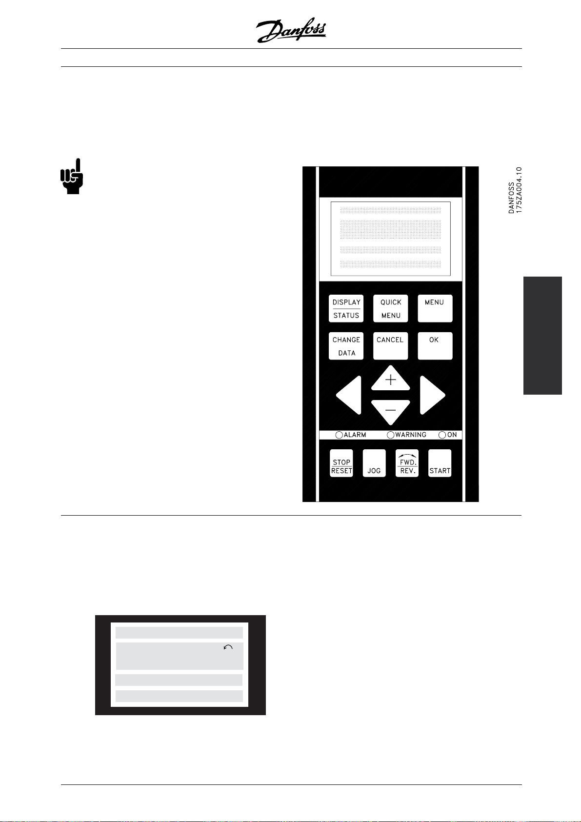
All data are indicated by means of a 4-line alphanumeric
display, which in normal operation is able show
4 measurements and 3 operating conditions
continuously. During programming, all the information
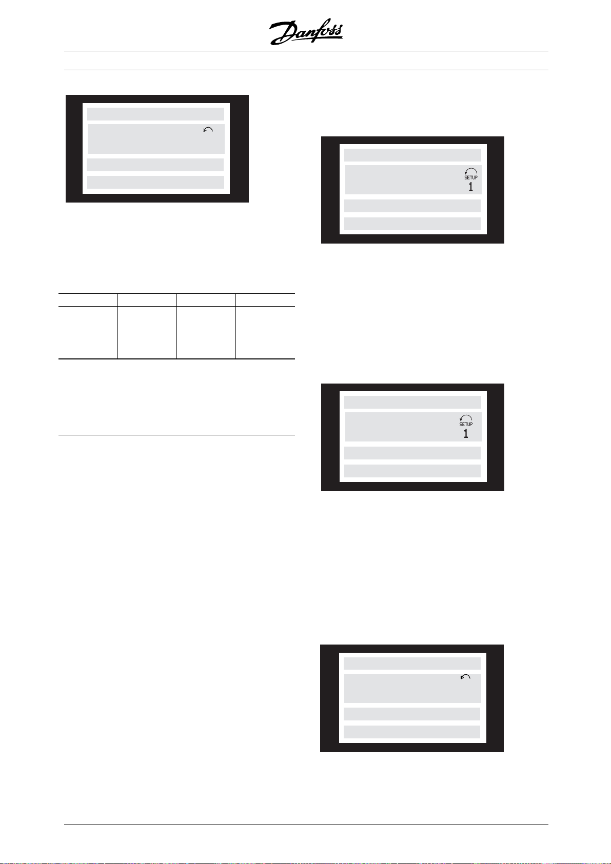
■ Display
The LCD-displayhas rear lighting and a total of 4
alpha-numeric lines together with a box that shows
the direction of rotation (arrow) and the chosen
Setup as well as the Setup in which programming
is taking place if that is the case.
1st line
2nd line
3rd line
4th line
12345678901234567890
SETUP
12345678
1
12345678901234567890
12345678901234567890
1st line shows up to 3 measurements continuously
in normal operating status or a text which
explains the 2nd line.
2nd line shows a measurement with related
unit continuously, regardless of status (except
inthecaseofalarm/warning).
175ZA443.10
3rd line is normally blank and is used in the menu
mode to show the selected parameter number or
parameter group number and name.
4th line is used in operating status for showing
astatustextorindatachangemodeforshowing
the value of the selected parameter.
MG.03.H3.02 - VLT is a registered Danfoss trademark
23
Page 24
VLT®FCM Series
An arrow indicates the direction of rotation
of the motor. Furthermore, the Setup
which has been selected as the Active
Setup in parameter 004 is shown. When
programming another Setup than the
Active Setup, the number of the Setup
which is being programmed will appear
to the right. This second Setup number
will flash.
■ LEDs
At the bottom of the control panel is a red alarm LEDand
a yellow warning LED, as well as a green voltage LED.
red yellow green
If certain threshold values are exceeded, the alarm
and/or warning lamp lights up together with a status
and alarm text on the control panel.
The voltage LED is activated when the FC motor
receives voltage; at the same time the rear
lighting of the display will be on.
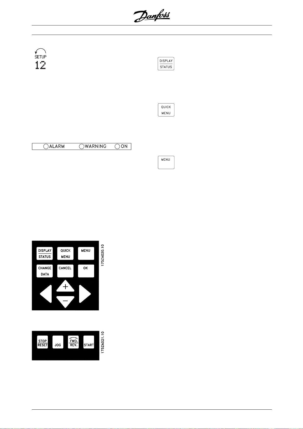
■Control key functions
[DISPLAY / STATUS] is used for
selecting the mode of display
or for changing back to Display
mode from either the Quick
menu mode or the Menu mode.
[QUICK MENU] is used for
programming the parameters
that belong under the Quick
menu mode. It is possible to
switch directly between Quick
menu mode and Menu mode.
[MENU] is used for programming
all parameters. It is possible to
switch directly between Menu
mode and Quick menu mode.
■ Control keys
The control keys are divided into functions. This
means that the keys between display and indicator
LEDs are used for parameter Setup, including choice
of display indication during normal operation.
Keys for local control are found under the
indicator LEDs.
24
MG.03.H3.02 - VLT is a registered Danfoss trademark
Page 25
VLT®FCM Series
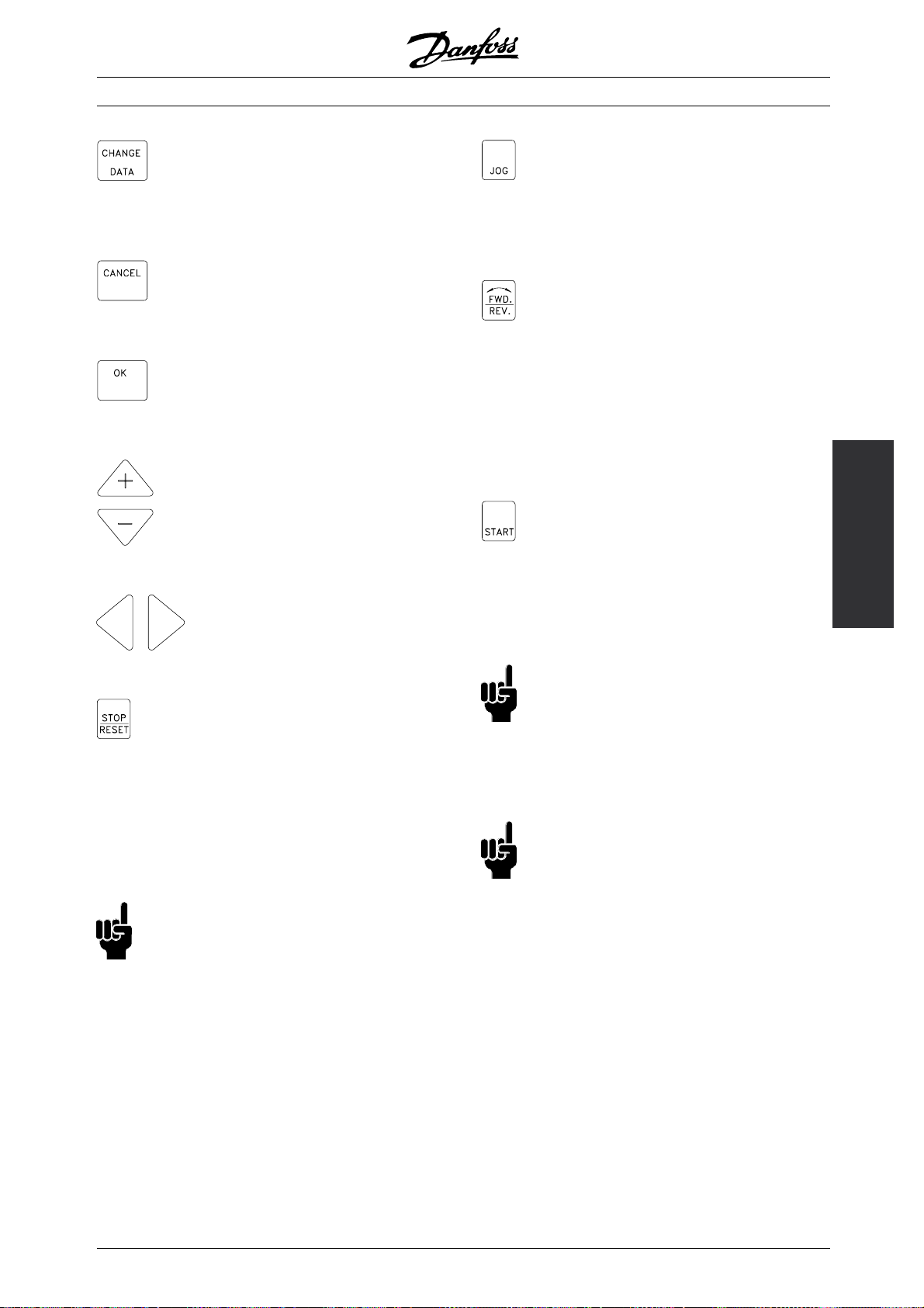
[CHANGE DATA] is used for
changing the parameter selected
either in the Menu mode or the
Quick menu mode.
[CANCEL] is used if a change of
the selected parameter is not to
be carried out.
[OK] is used for confirming
a change of the parameter
selected.
[+/-] is used for selecting
parameter and for changing
the chosen parameter or for
changing the read out in line 2.
[<>] is used for selecting group
and to move the cursor when
changing numerical parameters.
[JOG] overrides the output
frequency to a preset frequency
while the key is kept down. Can
be selected via parameter 015
to be active or inactive.
[FWD / REV] changes the
direction of rotation of the motor,
which is indicated by means of
the arrow on the display although
only in Local. Can be selected
via parameter 016 to be active
or inactive (parameter 013 must
be set to [1] or [3] and parameter
200 set to [1].
[START] is used for starting the
FC motor after stop via the [Stop]
key. Is always active, but cannot
override a stop command given
via the terminal strip.
Installation
[STOP / RESET] is used for
stopping or for resetting the FC
motor after a drop-out (trip). Can
be selected via parameter 014
to be active or inactive. If stop
is activated, line 2 will flash, and
[START] must be activated.
NB!:
Pressing [STOP/RESET] will prevent motor
from running also with disconnected
LCP 2. Restarting is only possible via
the LCP 2 [START] key.
NB!:
he keys for local control have been
If t
selected as active, they will remain active
both when the frequency has been set for
Local Control and for Remote Control via parameter
002, although with the exception of [FWD/REV],
which is only active in Local operation.
NB!:
If no external stop function has been selected
and the [STOP] key has been selected as
inactive via parameter 014, the FC motor
can be started and can only be stopped by
disconnecting the voltage to the motor.
■ Display read-out state
The display read-out state can be varied - see the list
on page 32 - depending on whether the FC motor is
in normal operation or is being programmed.
■ Display mode
In normal operation, up to 4 different operating
variables can be indicated continuously: 1,1 and 1,2
and 1,3 and 2, and in line 4 the present operating
status or alarms and warnings that have arisen.
MG.03.H3.02 - VLT is a registered Danfoss trademark
25
Page 26
VAR 1.1 VAR 1.2 VAR 1.3
SETUP
VAR 2
1
VLT®FCM Series
195NA113.10
• Read-out state I:
This read-out state is standard after starting
up or after initialisation.
FREQUENCY
STATUS
■Display mode - selection of read-out state
There are three options in connection with the
choice of read-out state in the Display mode - I, II
and III. The choice of read-out state determines the
number of operating variables read out.
Read-out state: I: II: III:
Line 1 Description for
operating variable
in line 2
The table below gives the units linked to the
variables in the first and second line of the
display (see parameter 009).
Operating variable: Unit:
Reference [%]
Reference [unit]*
Feedback [unit]*
Frequency [Hz]
Frequency x scaling [-]
Motor current [A]
To rq ue [ %]
Power [kW]
Power [HP]
Motor voltage [V]
DC-link voltage [V]
FC thermal [%]
Hours run [Hours]
Input status, dig. Input [Binary code]
External reference [%]
Status word [Hex]
Heat sink temp. [ºC]
Alarm word [Hex]
Control word [Hex]
Warning word 1 [Hex]
Warning word 2 [Hex]
Analog input 1 [mA]
Analog input 2 [V]
*) Select in parameter 416. The unit is shown in readout state 1 line 1
otherwise ’U’ is shown.
Operating variables 1,1 and 1,2 and 1,3 in the first
line, and operating variable 2 in the second line are
selected via parameter 009, 010, 011 and 012.
Data value for
3operating
variables in line
1
Description for
3operating
variables in line
1
50.0 Hz
MOTOR IS RUNNING
Line 2 gives the data value of an operating variable with
related unit, and line 1 provides a text which explains
line 2, cf. table. In the example, Frequency has
been selected as variable via parameter 009. During
normal operation another variable can immediately
be read out by using the [+/-] keys.
• Read-out state II:
Switching between read-out states I and II is effected
by pressing the [DISPLAY / STATUS] key.
24.3% 30.2% 13.8A
50.0 Hz
MOTOR IS RUNNING
In this state, data values for four operating values
are shown at the same time, giving the related
unit, cf. table. In the example, Reference, Torque,
Current and Frequency are selected as variables
in the first and second line.
• Read-out state III:
This read-out state can be held as long as the
[DISPLAY/STATUS] key is pressed. When the key is
released, the system switches back to Read-out state
II, unless the key is pressed for less than approx. 1 sec.
REF% TORQUE CURR A
SETUP
50.0 Hz
MOTOR IS RUNNING
This is where parameter names and units for
operating variables in the first line are given operating variable 2 remains unchanged.
1
26
MG.03.H3.02 - VLT is a registered Danfoss trademark
Page 27
VLT®FCM Series
■Quick menu mode versus Menu mode
The FC motor series can be used for practically
all assignments, which is why the number of
parameters is quite large. Also, this series offers
a choice between two programming modes - a
Menu mode and a Quick menu mode.
• The Quick menu takes the user through a number
of parameters that may be enough to get the
motor to run nearly optimally, if the factory setting
for the other parameters takes the desired control
functions into account, as well as the configuration
of signal inputs/outputs (control terminals).
• The Menu mode makes it possible to select
and change all parameters at the user’soption.
However, some parameters will be "missing",
depending on the choice of configuration (parameter
100), e.g. open loop hides all the PID parameters.
In addition to having a name, each parameter is linked
up with a number which is the same regardless of
the programming mode. In the Menu mode, the
parameters are divided into groups, with the first digit
of the parameter number (from the left) indicating the
group number of the parameter in question.
Regardless of the mode of programming, a change
of a parameter will take effect and be visible both in
the Menu mode and in the Quick menumode.
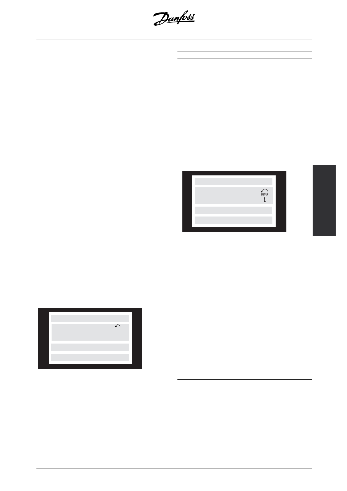
■Quick Setup via Quick menu
The Quick Setup starts with pressing the [QUICK
MENU] key, which brings out the following
read-out on the display:
QUICK MENU X OF Y
SETUP
50.0 Hz
1
001 LANGUAGE
ENGLISH
At the bottom of the display, the parameter number
and name are given together with the status/value
of the first parameter under
time the [Quick Menu] key is pressed after the unit
has been switched on, the read-outs will always
startatpos. 1-seetabl
Quick Setup. The first
ebelow.
Pos.: No.: Parameter: Unit:
1 001 Language
2 200 Direction of rotation
3 101 Torque characteristic
4 204 Min. reference [Hz]
5 205 Max. reference [Hz]
6 207 Ramp up time [sec.]
7 208 Ramp down time [sec.]
8 002 Local/remote control
9 003 Local reference
10 500 Bus address
■ Menu mode
The Menu mode is started by pressing the [MENU] key,
which produces the following read-out on the display:
FREQUENCY
50.0 Hz
0 KEYB.&DISPLAY
Line 3 on the display shows the parameter
group number and name.
■Parameter groups
IntheMenumodetheparametersaredivided
into groups. Selection of parameter group is
effected by means of the [<>] keys.
The following parameter groups are accessible:
Group no. Parameter group:
0Operation&Display
1Load&Motor
2 References & Limits
3 Inputs & Outputs
4 Special functions
5 Serial communication
6Technicalfunctions
*For information on parameter group 800 and 900
for PROFIBUS, please see the FCM Profibus manual
MG.03.EX.YY.
When the desired parameter group has been
selected, each parameter can be chosen by
means of the [+/-] keys:
Installation
■ Parameter selection
The selection of parameter is effected by means of the
[+/-] keys. The following parameters are accessible:
MG.03.H3.02 - VLT is a registered Danfoss trademark
27
Page 28
VLT®FCM Series
FREQUENCY
50.0 Hz
001 LANGUAGE
ENGLISH
The 3rd line of the display shows the parameter
number and name, while the status/value of the
selected parameter is shown in line 4.
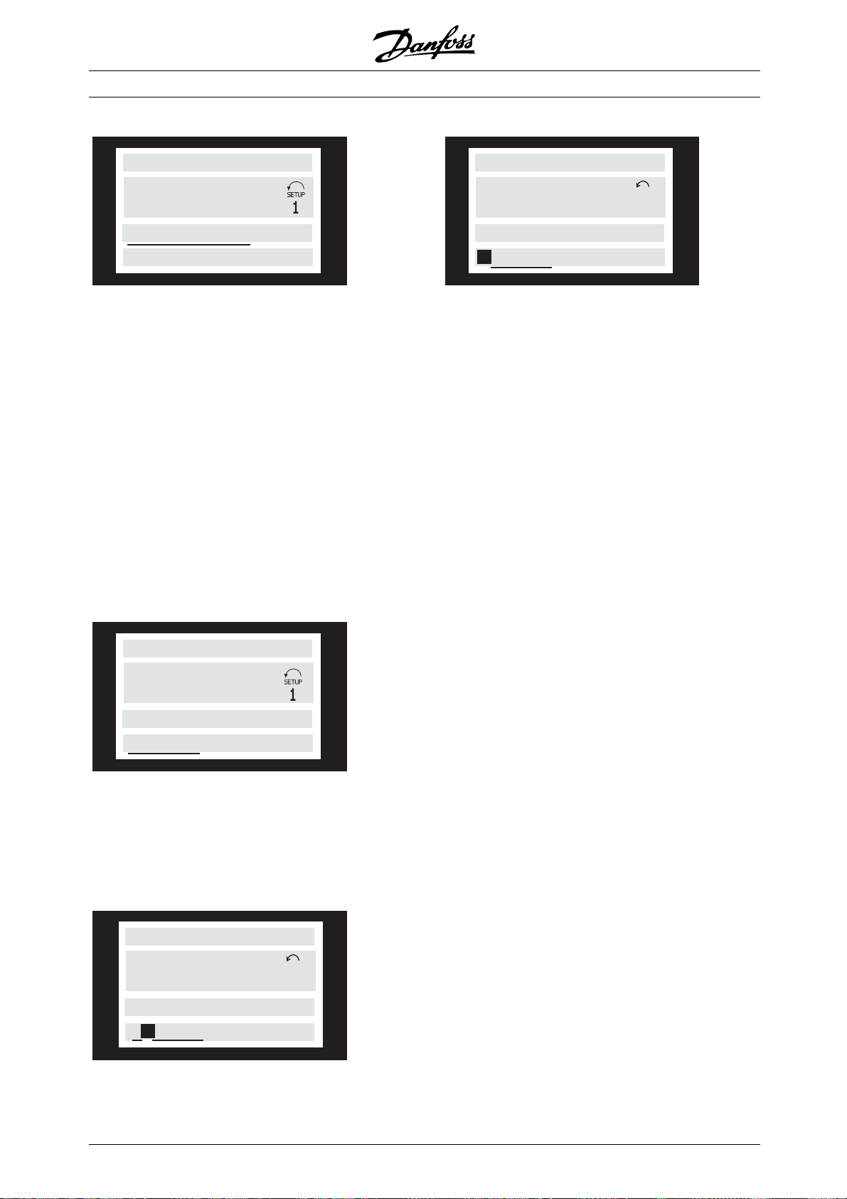
■ Changing data
Regardless of whether a parameter has been selected
under the Quick menu or the Menu mode, theprocedure
for changing data is the same. Pressing the [CHANGE
DATA] key gives access to changing the selected
parameter, following which the underlining in line 4
will flash on the display. The procedure for changing
data depends on whether the selected parameter
represents a numerical data value or a text value.
■Changing a text value
If the selected parameter is a text value, the text value
is changed by means of the [+/-] keys.
FREQUENCY
SETUP
50.0 Hz
130 START FREQUENCY
10.0 HZ
The chosen digit is indicated by the digit flashing. The
bottom display line shows the data value that will be
entered (saved) when signing off with [OK].
1
FREQUENCY
50.0 Hz
001 LANGUAGE
ENGLISH
The bottom display line shows the text value that will be
entered (saved) when acknowledgement is given [OK].
■Infinitely variable change of numeric data value
If the chosen parameter represents a numeric data
value, a digit is first selected by means of the [<>] keys.
FREQUENCY
SETUP
50.0 Hz
130 START FREQUENCY
09.0 HZ
1
Then the chosen digit is changed infinitely variably
by means of the [+/-] keys:
28
MG.03.H3.02 - VLT is a registered Danfoss trademark
Page 29
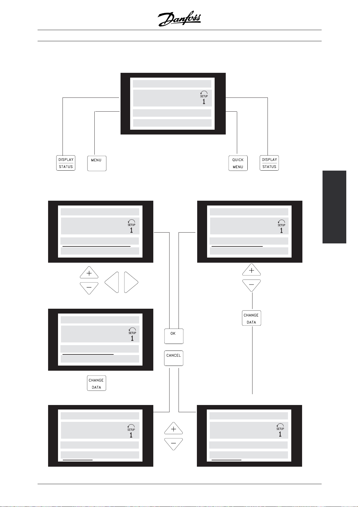
■ Menu structure
VLT®FCM Series
DISPLAY MODE
VAR 1.1 VAR 1.2 VAR 1.3
▲
▲
VAR 2
STATUS
▲
MENU MODE
FREQUENCY
50.0 HZ
0 KEYB.&DISPLAY
Choice of
parameter
DATA MODE
FREQUENCY
▲
Choice of
group
▲
▲
QUICK MENU MODE
QUICK MENU 1 OF 13
Installation
50.0 HZ
001 LANGUAGE
ENGLISH
50.0 HZ
001 LANGUAGE
ENGLISH
DATA CHANGE MODE
FREQUENCY
50.0 HZ
001 LANGUAGE
ENGLISH
175ZA446.11
MG.03.H3.02 - VLT is a registered Danfoss trademark
▲
▲
Choice of
data value
▲
DATA CHANGE MODE
QUICK MENU 1 OF 13
50.0 HZ
001 LANGUAGE
ENGLISH
29
Page 30
■ Service plug kit (175N2546)
Purpose:
To run LCP2 and PROFIBUS at the same time. The
service plug can be used with FCM 300 of serial
number 03Gxxx and software version as from 2.03.
Used together with cable for plug kit 175N0162.
■ Plug kit (175N2545)
Purpose
To make a plugable connection between
LCP 2 and FCM 300.
Used together with cable for plug kit 175N0162.
VLT®FCM Series
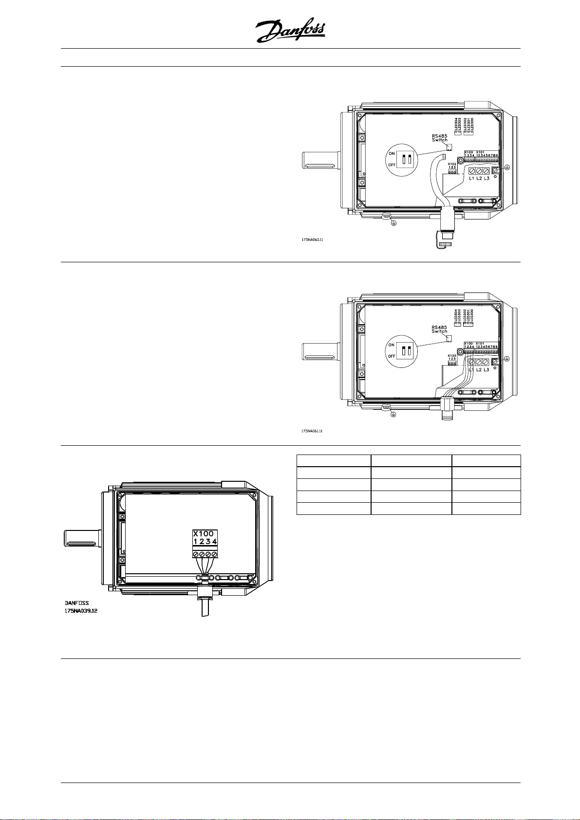
■ Remote mounting kit (175N0160)
Connections
Colour of wire/ Te r mi n al X 1 00 / D-sub pin
yellow 1 8
green 2 9
red 3 2
blue 4 3
30
MG.03.H3.02 - VLT is a registered Danfoss trademark
Page 31

■ Remote mounting kit cont.
VLT®FCM Series
■Potentiometer option (177N0011)
Option to control the reference by means of a
potentiometer. The option is mounted instead of a
cable bracket. The potentiometer is operated
removing the blind plug to set the desired reference,
and then mount the blind plug again.
Colour of wire Terminal on X101
White 2 (analog input)
Red 8(0V)
Black 7(+10V)
Installation
by
MG.03.H3.02 - VLT is a registered Danfoss trademark
31
Page 32

VLT®FCM Series
■ Local Operation Pad (LOP) (175N0128) IP65
Wiring
Colour of wire Te rm i na l Function
White 2 Reference
Brown 3 Reset
Purple * or Grey 4 See table under button
Green 5 See table under button
Red 6 +24V
Yellow 7 +10V
Blue 8 Ground
Use the +/- keys to set reference
Local Operation Panel (LOP) 175N0128 IP 65 Fixture for LOP 175N1114
* Can be orange in some cables
Functions/settings Key I (Start) Key II (Start)
Default - Dual speed operation (connect
purple wire):
Runonset
reference (+/-)
Runon10Hz**jog
speed
No changes to factory setting.
Function 2 - Dual mode operation
RunwithSetup1 RunwithSetup2 Stop (and reset* - if trip)
(connect purple wire)
Select desired modes of operation
in Setups 1 and 2 (use para. 4-6)
Parameter 335 = 18 (select Setup)
Function 3 - Dual direction operation
Run forward Run reverse Stop (and reset* - if trip)
(connect grey wire)
Parameter 335 = 10 (start reversing)
Parameter 200 = 1 (both directions)
*If no reset is required, do not connect the brown wire
**or set parameter 213
At power up the unit will always be in stop mode.
Set reference will be stored during power down.
If permanent start mode is desired, connect
terminal 6 to terminal 4 and do not connect
purple/grey wire to terminal 4. This means the
stop function on LOP is disabled.
Key (Stop)
Stop (and reset* - if trip)
32
MG.03.H3.02 - VLT is a registered Danfoss trademark
Page 33

NB!:
After fitting, cut off or isolate excess wire.
VLT®FCM Series
Installation
MG.03.H3.02 - VLT is a registered Danfoss trademark
33
Page 34

VLT®FCM Series
001 Language
(LANGUAGE)
Value:
✭English (ENGLISH)
German (DEUTSCH)
French (FRANCAIS)
Danish (DANSK)
Spanish (ESPAÑOL)
Italian (ITALIANO)
State when delivered may vary from factory setting.
Function:
The choice in this parameter defines the language
to be used on the display.
Description of choice:
There is a choice of English [0], German[1], French
[2], Danish [3], Spanish [4] and Italian [5].
002 Local/remote control
(OPERATION SITE)
Value:
✭Remote control (REMOTE)
Local control (LOCAL)
Function:
There is a choice of two methods of controlling the FC
motor: Remote control [0] and Local control [1].
Description of choice:
If Remote control [0] is selected, the FC motor
can be controlled via:
1. The control terminals or the serial
communication port .
2. The [START] key. However, this cannot overrule
Stop commands (also start-disable) entered via the
digital inputs or the serial communication port.
3. The [STOP], [JOG] and [RESET] keys, provided that
these are active (see parameters 014, 015 and 017).
If Local control [1] is selected, the FC motor
can be controlled via:
1. The [START] key. However, this cannot override
Stop commands on the digital terminals (if [2] or
[4] has been selected in parameter 013).
2. The [STOP], [JOG] and [RESET] keys, provided that
these are active (see parameters 014, 015 and 017).
3. The [FWD/REV] key, provided that this has been
activated in parameter 016 and that in parameter
013 a choice of [1] or [3] has been made.
[0]
[1]
[2]
[3]
[4]
[5]
[0]
[1]
4. Via parameter 003 the local referencecan
be controlled by means of the "Arrow up"
and "Arrow down" keys.
003 Local reference
(LOCAL REFERENCE)
Value:
Par 013 set for [1] or [2]:
0-f
MAX
✭ 000.000
Par 013 set for [3] or [4] and par. 203 = [0] set for:
-Ref
Ref
MIN
MAX
✭ 000.000
Par 013 set for [3] or [4] and par. 203 = [1] set for:
MAX
-+Ref
MAX
✭ 000.000
-Ref
Function:
This parameter allows manual setting of the
desired reference value (speed or reference for
the selected configuration, depending on the
choice made in parameter 013).
The unit follows the configuration selected in
parameter 100, provided that Process regulation,
closed loop [3] has been selected.
Description of choice:
Local [1] must be selected in parameter 002
for this parameter to be used.
The set value is saved in the case of a voltage
dropout, see parameter 019.
InthisparameterDataChangeModeisnotexited
automatically (after time out).
Local reference cannot be set via the serial
communication port.
Warning: Since the value set is remembered
after the power has been cut, the motor
may start without warning when the
power is reinstated; if parameter 019 is changed
to Auto restart, use saved ref. [0].
004 Active Setup
(ACTIVE SETUP)
Value:
Factory Setup (FACTORY SETUP)
✭Setup 1 (SETUP 1)
Setup 2 (SETUP 2)
Multi Setup (MULTI SETUP)
Function:
The choice in this parameter defines the Setup number
you want to control the functions of the FC motor.
[0]
[1]
[2]
[5]
✭
= factory setting. () = display text [] = value for use in communication via serial communication port
34
MG.03.H3.02 - VLT is a registered Danfoss trademark
Page 35

VLT®FCM Series
All parameters can be programmed in two individual
parameter Setups, Setup 1 and Setup 2. In addition,
there is a pre-programmed Setup, called Factory
Setup, that cannot be modified.
Description of choice:
Factory Setup [0] contains the factory data. Can
be used as a data source if the other Setups are
to be returned to a known state.
Parameters 005 and 006 allow copying from
one Setup to the other.
Setups 1 [1] and 2 [2] are two individual Setups
that can be selected as required.
Multi-Setup [5] is used if remote-mounting switching
between Setups is desired. Terminals 2, 3, 4, and
5 as well as the serial communication port can be
used for switching between Setups.
005 Programming Setup
(EDIT SETUP)
Value:
Factory Setup (FACTORY SETUP)
Setup 1 (SETUP 1)
Setup 2 (SETUP 2)
✭Active Setup (ACTIVE SETUP)
Function:
The choice is of the Setup in which programming
(change of data) is to occur during operation.
It is possible to programme the two Setups
independently of the Setup selected as the Active
Setup (selected in parameter 004).
[0]
[1]
[2]
[5]
006 Copying of Setups
(SETUP COPY)
Value:
✭No copying (NO COPY)
Copy to Setup 1 from# (COPY TO SETUP 1)
Copy to Setup 2 from# (COPY TO SETUP 2)
Copy to Setup all from# (COPY TO ALL)
# = the Setup selected in parameter 005
Function:
A copy is made from the Setup selected in
parameter 005 to one of the other Setups or to
all the other Setups simultaneously.
NB!:
Copying is only possible in Stop Mode (motor
stopped on a Stop command). Copying will
take max. 3 seconds and has ended when
parameter 006 has returned to value 0.
007 LCP copy
(LCP COPY)
Value:
✭No copying (NO COPY)
Upload all parameters (UPLOAD ALL PARAM)
Download all parameters (DOWNLOAD ALL)
Download power-independent par.
(DOWNLOAD SIZE INDEP.)
Function:
Parameter 007 is used if it is desired to use the
integrated copying function of the control panel.
You can therefore easily copy parameter value(s)
from one FC motor to another.
[0]
[1]
[2]
[5]
[0]
[1]
[2]
[3]
Programming
Description of choice:
The Factory Setup [0] contains the factory data and
can be used as a data source if the other Setups
aretobereturnedtoaknownstate.
Setups 1 [1] and 2 [2] are individual Setups which can
be used as required. They can be programmed freely,
regardless of the Setup selected as the Active Setup
and thus controlling the functions of the FC motor.
NB!:
If a general change of data or a copying to
the Active Setup is effected, this immediately
affects the functioning of the unit.
✭ = factory setting. () = display text [] = value for use in communication via serial communication port
MG.03.H3.02 - VLT is a registered Danfoss trademark
Description of choice:
Select Upload all parameters [1] if all parameter
values are to be transmitted to the control panel.
Select Download all parameters [2] if all transmitted
parameter values are to be copied to the FC motor
on which the control panel has been mounted.
Select Download power-independent par. [3] if
only the power-independent parameters are to be
downloaded. This is used if downloading to a FC
motor that has a different rated power than the one
from where the parameter Setup originates.
NB!:
Uploading/Downloading can only be carried
out in the Stop mode and only between
units with the same m
(see par. 626 value m
ajor database version
ajor.minor)
35
Page 36

VLT®FCM Series
008 Display scaling of motor frequency
(FREQUENCY SCALE)
Value:
0.01 - 100.00
✭1.00
[1 - 10000]
[100]
Function:
This parameter chooses the factor to be multiplied
by the motor frequency, f
, for presentation in
M
the display, when parameters 009-012 have been
set for Frequency x Scaling [5].
Description of choice:
Set the desired scaling factor.
009 Display line 2
(DISPLAY LINE 2)
Value:
None
Reference [%] (REFERENCE [%])
Reference [unit] (REFERENCE [UNIT])
Feedback [unit] (FEEDBACK [UNIT])
✭Frequency [Hz] (FREQUENCY [HZ])
Frequency x Scaling [-](FREQUENCY X SCALE)
Motor current [A] (MOTOR CURRENT [A])
Torque [%] (TORQUE [%])
Power [kW] (POWER [KW])
Power [HP] (POWER [HP] [US])
Motor voltage [V] (MOTOR VOLTAGE [V])
DC link voltage [V] (DC LINK VOLTAGE [V])
Thermal load, FC [%] (FC THERMAL [%])
Hours run [Hours] (RUNNING HOURS)
Digital input [Binary code] (DIGITAL INPUT [BIN])
External reference [%] (EXTERNAL REF [%])
Status word [Hex] (STATUS WORD [HEX])
Heat sink temp. [°C] (HEATSINK TEMP [°C])
Alarm word [Hex] (ALARM WORD [HEX])
Control word[Hex] (CONTROL WORD [HEX])
[11]
[12]
[14]
[15]
[16]
[21]
[22]
[25]
[26]
[27]
Warning word 1 [Hex]
(WARNING WORD 1 [HEX])
[28]
Warning word 2 [Hex]
(EXTENDED STATUS WORD [HEX])
Analog input 1 [mA] (ANALOG INPUT 1 [MA])
Analog input 2 [V](ANALOG INPUT 2 [V])
[29]
[30]
[31]
Function:
This parameter allows a choice of the data value
to be displayed in line 2 of the display.
Parameters 010-012 enable the use of three additional
data values to be displayed in line 1.
For display read-outs, press the [DISPLAY/STATUS]
button, see also page 31.
[0]
[1]
[2]
[3]
[4]
[5]
[6]
[7]
[8]
[9]
NB!:
In parameter 009, "none" [0] cannot be selected.
Description of choice:
Reference [%] corresponds to the total reference
(sum of digital/analogue/preset/bus/freeze ref./
catch-up and slow-down).
Reference [unit] gives the sum of the references
using the unit stated on the basis of configuration
in parameter 100 (Hz, Hz and rpm).
Feedback [unit] gives the status value of
terminal 1 and 2 using the unit/scale selected
in parameter 414, 415 and 416.
Frequency [Hz] gives the motor frequency, i.e. the
output frequency to the motor.
Frequency x Scaling [-] corresponds to the
present motor frequency f
multiplied by a factor
M
(scaling) set in parameter 008.
Motor current [A] states the phase current of the
motor measured as effective value.
Torque [%] gives the current motor load in relation
to the rated motor torque.
Power [kW] states the actual power consumed
by the motor in kW.
Power [HP] states the actual power consumed
by the motor in HP.
Motor voltage [V] states the voltage supplied
to the motor.
DC link voltage [V] states the intermediate circuit
voltage in the FC motor.
Thermal load, FC [%] states the calculated/ estimated
thermal load on the FC motor. 100% is the cut-out limit.
Hours run [Hours] states the number of hours that the
motor has run since the latest reset in parameter 619.
Digital input [Binary code] states the signal states
from the 4 digital terminals (2, 3, 4 and 5). Input
5 corresponds to the bit at the far left. ’0’ =no
signal, ’1’ = connected signal.
External reference [%] gives the sum of the
external reference as a percentage (the sum
of analogue/ pulse/bus).
Status word [Hex] gives the status word sent
via the serial communication port in Hex code
from the FC motor.
Heat sink temp. [°C] states the present heat sink
temperature of the FC motor. The cut-out limit is 90
± 5°C; cutting back in occurs at 60 ± 5°C.
Alarm word [Hex] indicates one or several alarms
in a Hex code. See page 74.
Control word [Hex] indicates the control word for
the FC motor. See Serial communication.
= factory setting. () = display text [] = value for use in communication via serial communication port
✭
36
MG.03.H3.02 - VLT is a registered Danfoss trademark
Page 37

VLT®FCM Series
Warning word 1 [Hex] indicates one or more warnings
in a Hex code. See page 74 for further information.
Extended status word [Hex] indicates one or
more status states in a Hex code. See page
74 for further information.
Analog input 1 [mA]states the signal value on terminal 1.
Analog input 2[V] states the signal value on terminal 2.
010 Display line 1.1
(DISPLAY LINE 1.1)
Value:
✭Reference [%]
See parameter 009.
Function:
This parameter enables a choice of the first of three data
values to be shown on the display, line 1, position 1.
Description of choice:
There is a choice of 24 different data values,
see parameter 009.
011 Display line 1.2
(DISPLAY LINE 1.2)
Value:
✭Motor current [A]
See parameter 009
[1]
[1]
012 Display line 1.3
(DISPLAY LINE 1.3)
Value:
✭Power [kW]
See parameter 009
Function:
This parameter enables a choice of the third of the three
data values to be shown on the display, line 1, position 3.
Display read-outs are made by pressing the
[DISPLAY/STATUS] button, see also page 31.
Description of choice:
There is a choice of 24 different data values,
see parameter 009.
013 Local Control/Configuration as
parameter 100
(LOCAL CTRL/CONFIG.)
Value:
Local not active (DISABLE)
LCP control and open loop.
(LCP CTRL/OPEN LOOP)
LCP digital control and open loop.
(LCP+DIG CTRL/OP.LOOP)
LCP control/as parameter 100.
(LCP CTRL/AS P100)
✭LCP digital control/as parameter 100.
(LCP+DIG CTRL/AS P100)
[8]
[0]
[1]
[2]
[3]
Programming
[4]
Function:
This parameter enables a choice of the second
of the three data values to be shown on the
display, line 1, position 2.
For Display read-outs, press the [DISPLAY/STATUS]
button, see also page 31.
Description of choice:
There is a choice of 24 different data values,
see parameter 009.
= factory setting. () = display text [] = value for use in communication via serial communication port
✭
Function:
This is where the desired function is to be selected
if Local control has been chosen in parameter 002.
See also the description of parameter 100.
Description of choice:
If Local not active [0] is selected, a possible setting
of Local reference via parameter 003 is blocked.
It is only possible to change to Local not active [0]
from one of the other setting options in parameter
013, when the FC motor has been set to Remote
control [0] in parameter 002.
LCP control and open loop [1] is used when the
speed is to be adjustable (in Hz) via parameter
003, when the FC motor has been set to Local
control [1] in parameter 002.
If parameter 100 has not been set to Speed regulation
open loop [0], switch to Speed regulation open loop [0].
LCP digital control and open loop [2] functions as LCP
control and open loop [1], the only difference being that
MG.03.H3.02 - VLT is a registered Danfoss trademark
37
Page 38

VLT®FCM Series
when parameter 002 has been set to Local operation
[1], the motor is controlled via the digital inputs.
LCP control/as parameter 100 [3] is selected if the
reference is to be set via parameter 003.
LCP digital control/as parameter 100 [4] functions as
LCP control/as parameter 100 [3], although, when
parameter 002 has been set to Local operat ion [1], the
motor may be controlled via the digital inputs.
NB!:
Shift from Remote control to LCP digital
control and open loop:
The present motor frequency and direction of rotation
must be maintained. If the present direction of rotation
does not correspond to the reversing signal (negative
reference), the motor frequency f
S
hift from LCP digital control and open loop
willbesetat0Hz.
M
to Remote control:
The selected configuration (parameter 100)
will be active. Shifts are effected without
any abrupt movement.
hift from Remote control to LCP control/as parameter
S
100 or LCP digital control/as parameter 100.
The present reference will be maintained. If the reference
signal is negative, the local reference will be set at 0.
hift from LCP control/as parameter 100 or LCP
S
remote control as parameter 100 to Remote control.
The reference will be replaced by the active reference
signal from the remote control..
NB!:
If Enable is selected, the [STOP] key
overrules all Start commands.
015 Local jog
(LOCAL JOGGING)
Value:
✭Not possible (DISABLE)
Possible (ENABLE)
Function:
In this parameter, the jog function can be enabled/
disabled on the control panel.
Description of choice:
If Disable [0] is selected in this parameter, the
[JOG] key will be inactive.
016 Local reversing
(LOCAL REVERSING)
Value:
✭Not possible (DISABLE)
Possible (ENABLE)
Function:
In this parameter, the reversing function can be
enabled/disabled on the control panel. This key can
only be used if parameter 002 has been set to Local
operation [1] and parameter 013 to LCP control with
open loop [1] or LCP control as parameter 100 [3].
[0]
[1]
[0]
[1]
Description of choice:
014 Local stop
(LOCAL STOP)
If Disable [0] is selected in this parameter, the
[FWD/ REV] key will be inactive.
See parameter 200.
Value:
Not possible (DISABLE)
✭Possible (ENABLE)
Function:
This parameter disables/enables the local stop
function in question from the control panel. This
key is used when parameter 002 has been set
[0]
[1]
017 Local reset of trip
(LOCAL RESET)
Value:
Notpossible(DISABLE)
✭Possible (ENABLE)
for Remote control [0] or Local [1].
Function:
Description of choice:
If Disable [0] is selected in this parameter, the
[STOP] key will be inactive.
In this parameter, the reset function can be
selected/removed from the keyboard. This key can
be used when parameter 002 has been set for
Remote control [0] or Local control [1].
= factory setting. () = display text [] = value for use in communication via serial communication port
✭
38
MG.03.H3.02 - VLT is a registered Danfoss trademark
[0]
[1]
Page 39

VLT®FCM Series
Description of choice:
If Disable [0] is selected in this parameter, the
[RESET] key will be inactive.
NB!:
Only select Disable [0] if an external reset signal
has been connected via the digital inputs.
018 Lock for data chang e
(DATA CHANGE LOCK)
Value:
✭Not locked (NOT LOCKED)
Locked (LOCKED)
Function:
In this parameter, the software can "lock" the
control, which means that data changes cannot
be made via LCP 2 (however, this is still possible
via the serial communication port).
Description of choice:
If Locked[1] is selected, data changes cannot be made.
NB!:
In remote controlled operation (parameter
002), the start/stop condition at power up
will depend on the external control signals. If
Latched start is selected in parameter 332-335, the
motor will remain stopped at power up.
[0]
[1]
019 Operating state at power up, local control
(POWER UP ACTION)
Value:
Auto restart, use saved ref. (AUTO RESTART)
✭Forced stop, use saved ref. (LOCAL=STOP)
Forced stop, set ref. to 0 (LOCAL=STOP, REF=0)
Function:
Setting of the desired operating mode when the
mains voltage is reconnected.
This function can only be active in connection with
Local control [1] in parameter 002.
Description of choice:
Auto restart, use saved ref. [0] is selected if the unit
is to start up with the same local reference (set in
parameter 003) and the same start/stop conditions
(given via the [START/STOP] keys) that the FC
motor had before it was switched off.
Forced stop, use saved ref. [1] is used if the
unit is to remain stopped when the mains voltage
is connected, until the [START] key is pressed.
After the start command, the local reference
used is set in parameter 003.
Forced stop, set ref. to 0 [2] is selected if the unit is to
remain stopped when the mains voltage is connected.
Local reference (parameter 003) is reset.
[0]
[1]
[2]
Programming
✭ = factory setting. () = display text [] = value for use in communication via serial communication port
MG.03.H3.02 - VLT is a registered Danfoss trademark
39
Page 40

100 Configuration
(CONFIG. MODE)
Value:
✭Speed, open loop mode (SPEED OPEN LOOP)
Process, closed loop mode
(PROCESS CLOSED LOOP)
Function:
This parameter is used for selecting the configuration
to which the FC motor is to be adapted.
Description of choice:
If Speed, open loop mode [0] is selected, a
normal speed control (without feedback signal) is
obtained, but with automatic slip compensation,
ensuring a nearly constant speed at varying loads.
Compensations are active, but may be disabled
as required in parameter 133 - 136.
VLT®FCM Series
[0]
[1]
NB!:
Slip compensation (parameter 136) and
start (parameter 134) are not active if a
variable torque is used.
If Process, closed loop mode [3] is selected, the internal
process regulator will be activated, thereby enabling
accurate regulation of a process with respect to a given
process signal. The process signal can be set using
the actual process unit or as a percentage. A feedback
signal must be supplied from the process, and the
process setpoint must be adjusted. In process closed
loop both directions is n
NB!:
This is only possible in Stop Mode (motor
stopped on a Stop command).
101 Torque characteristics
(TORQUE CHARACT)
Value:
✭Constant torque (CONSTANT TORQUE)
Variable torque: low (VAR.TORQUE: LOW)
Var. torque: medium (VAR.TORQUE: MEDIUM)
Variable torque: high (VAR.TORQUE: HIGH)
Function:
In this parameter, the principle for adjusting the
U/f characteristics of the FC motor to the torque
characteristics of the load is selected.
Description of choice:
If Constant torque [1] is selected, a load-dependent U/f
characteristic is obtained in which the output voltage is
increased in the case of an increasing load (current) so
as to maintain constant magnetisation of the motor.
Select Variable torque low [2], Variable torque
medium [3] or Variable torque high [4] if the load
is square (centrifugal pumps, fans).
ot allowed in parameter 200.
[1]
[2]
[3]
[4]
102 Motor power
(MOTOR POWER)
Value:
XX.XX kW - depends on the FC motor
Function:
Read only parameter.
103 Motor voltage
(MOTOR VOLTAGE)
Value:
XX V- depends on the FC motor
Function:
Read only parameter.
104 Motor frequency
(MOTOR FREQUENCY)
Value:
XX.X Hz - depends on the FC motor
Function:
Read only parameter.
[XXXX]
[XX]
[XXX]
✭ = factory setting. () = display text [] = value for use in communication via serial communication port
40
MG.03.H3.02 - VLT is a registered Danfoss trademark
Page 41

105 Motor current
(MOTOR C URRENT)
Value:
XX.X X A- depends on the FC motor.
Function:
Read only parameter.
106 Rated motor speed
(MOTOR NOM. SPEED)
Value:
XX rpm - depends on the FC motor
Function:
Read only parameter.
117 Resonance damping
(RESONANCE DAMP.)
Value:
OFF - 100%
✭OFF %.
Function:
It is possible to optimise the resonance damping
in CT mode. The grade of the influence is
adjusted in this parameter.
The value may be set between 0% (OFF) and 100%.
100% corresponds to 50% reduction of U/F ratio.
Default value is OFF.
NB!:
Vibrations cannot be removed in all cases
at no load function.
[XXXX]
[OFF -100]
[OFF]
[XX]
VLT®FCM Series
If the active motor current is below 10%, the motor
voltage will be decreased by the speed mentioned
above until the voltage reaches the setting for Par.
117. If the active motor current comes over 20% the
voltage will be increased by the above mentioned
speed. If the active motor current reaches 40%
the motor voltage will be increased immediately to
normal motor voltage. The reduction in motor voltage
depends on the parameter 117 setting.
Description of choice:
Set the grade of Motor current [Imact] influence
on the U/F ratio between 0% (OFF) and 100%.
100% corresponds to 50% reduction of U/F
ratio. Default value is OFF.
NB!:
A change of selection will not become
active until the mains voltage has been
disconnected and reconnected.
Programming
Internal settings (fixed):
The resonance filter is active from 10% of
nominal speed and above.
In this case 5Hz and above.
Speed to go from 0 to nominal flux level: 500msSpeed
to go from 0 to nominal flux level: 500ms
Speed to go from nominal to 0 flux level: 500ms
Description of functionality:
The filter monitors the active motor current and
changes the motor voltage according to the
figure below. The filter reacts on levels referring
to the nominal motor current.
✭
= factory setting. () = display text [] = value for use in communication via serial communication port
MG.03.H3.02 - VLT is a registered Danfoss trademark
126 DC braking time
(DC BRAKING TIME)
Value:
0.0 - 60.0 sec.
✭10.0 sec.
DC braking see P132
Function:
This parameter is for setting the DC braking time
for which the DC braking voltage (parameter
132) is to be active.
0.0 sec. = OFF
[0-600]
[100]
41
Page 42

VLT®FCM Series
Description of choice:
Set the desired time.
127 DC brake cut-in frequency
(DC BRAKE CUT-IN)
Value:
0.0 - f
(PARAMETER 202)
MAX
[0 -]
0.0 Hz = OFF
DC braking see P132
Function:
This parameter is for setting the DC brake cut-in
frequency at which the DC braking voltage (parameter
132) is to be active, in connection with a Stop command.
Description of choice:
Set the desired frequency.
128 Motor thermal protection
(MOTOR THERM. PROTEC.)
Value:
✭Disable (DISABLE)
Enable (ENABLE)
Function:
FCM always disable [0]
[0]
[0]
[1]
time. P126, R127 and P132 are used for the
control of the DC braking.
The DC braking can also be activated directly
by a digital input.
Function:
The braking torque depends on the selected DC
braking voltage. The DC braking voltage is stated as
a percentage of maximum braking voltage.
Description of choice:
Set the desired voltage as a specified percentage
of maximum braking voltage.
NB!:
The DC braking voltage cannot be used
as a holding brake.
133 Start voltage
(START VOLTAGE)
Value:
0.00 - 100.00 V
[0-10000]
✭Depends on motor
Function:
You can set the motor voltage below the field weakening
point independently of the motor current. Use this
parameter to compensate too low starting torque.
The start voltage is the voltage at 0 Hz.
Description of choice:
If Disable [0] is selected no tripping is required
when the motor is overloaded.
132 DC braking voltage
(DC BRAKE VOLTAGE)
Value:
0 - 100 %
✭0%
Function:
DC braking:
If the stator in an asynchronous is supplied with
DC voltage, a braking torque will arise.
The braking torque depends on the selected
DC braking voltage.
For applying a braking torque by means of DC
braking the rotating field (AC) in the motor is
exchanged with a stationary field (DC)
The DC braking will be active when below cut
in frequency and stop is activated at the same
[v0-100]
[0]
NB!:
If the start voltage is set too high, it can lead
to magnetic saturation and motor overheating;
the FC motor may trip. Therefore take
care when using the start voltage.
Description of choice:
Set the desired start voltage.
134 Load compensation
(LOAD COMPENSATION)
Value:
0.0 - 300.0 %
✭100.0 %
[0-3000]
[1000]
Function:
In this parameter, the load characteristic is set. By
increasing the load compensation, the motor is given an
extra voltage and frequency supplement at increasing
loads. This is used e.g. in motors/applications in
= factory setting. () = display text [] = value for use in communication via serial communication port
✭
42
MG.03.H3.02 - VLT is a registered Danfoss trademark
Page 43
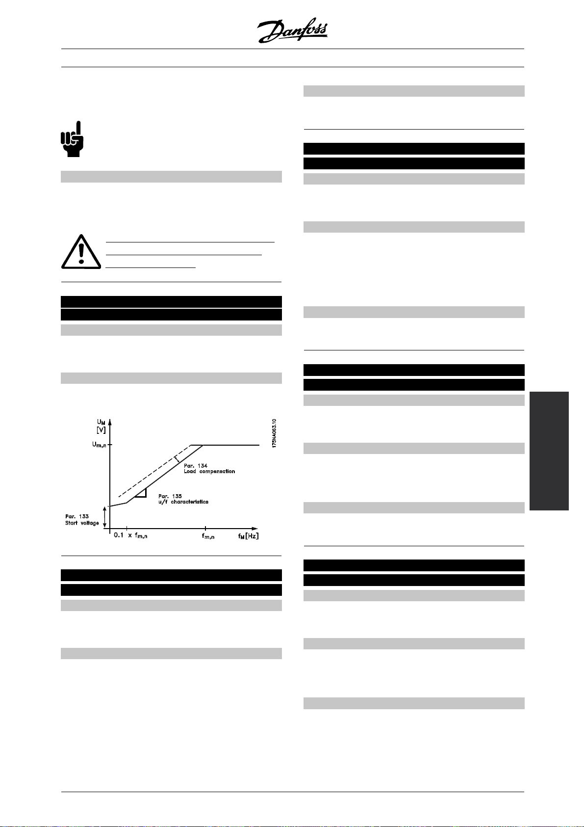
VLT®FCM Series
which there is a big difference between the full-load
current and idle-load current of the motor.
NB!:
If the value is too high the FC motor can
trip due to overcurrent.
Description of choice:
If the factory setting is not adequate, load
compensation must be set to enable the motor
to start at the given load.
Should be set to 0% in case of quick load
changes. Too high load compensation
may lead to instability.
135 U/f ratio
(U/F RATIO)
Value:
0.00 - 20.00 V/Hz
✭Motor dependent
Function:
The output voltage to the motor can be adjusted on
a linear basis from 0 to rated frequency.
[0-2000]
Description of choice:
Enter a % value of rated slip compensation.
137 DC holding voltage
(DCHOLDVOLTAGE)
Value:
0-100%
✭0 (OFF) %
Function:
This parameter is used to uphold the motor function
(holding torque) or to pre-heat the motor. DC
holding voltage is active at stopped motor when it
is set at a value which is different from 0. Coasting
stop will deactivate the function.
Description of choice:
Enter a percentage value.
138 Brake cut out frequency
(BRAKE RELEASE)
Value:
0.5 - 132 Hz (PARAMETER 200)
✭3.0 Hz
[0-100]
[0]
[5-]
[30]
136 Slip compensation
(SLIP COMP.)
Value:
-500.0 - +500.0 %
✭100.0 %
Function:
The rated slip compensation (factory setting) is
calculated on the basis of the motor parameters. In
parameter 136 the slip compensation can be adjusted
in detail. Optimizing makes the motor speed less load
dependent. This function is not active at the same
time as variable torque (parameter 101).
[-5000 - +5000]
[1000]
Function:
Here the frequency at which the external brake
is to be released is selected via output set in
parameter 340 during running.
Description of choice:
Set desired frequency.
139 Brake cut in frequency at activated stop
(BRAKE CUT IN)
Value:
0.5 - 132 Hz (PARAMETER 200)
✭3.0 Hz
Function:
Here the frequency at which the external brake is to
be activated is selected via output set in parameter
340 when the motor is ramping down to stop.
Description of choice:
Set the desired frequency.
See below speed profile for brake function.
Programming
[5-]
[30]
= factory setting. () = display text [] = value for use in communication via serial communication port
✭
MG.03.H3.02 - VLT is a registered Danfoss trademark
43
Page 44
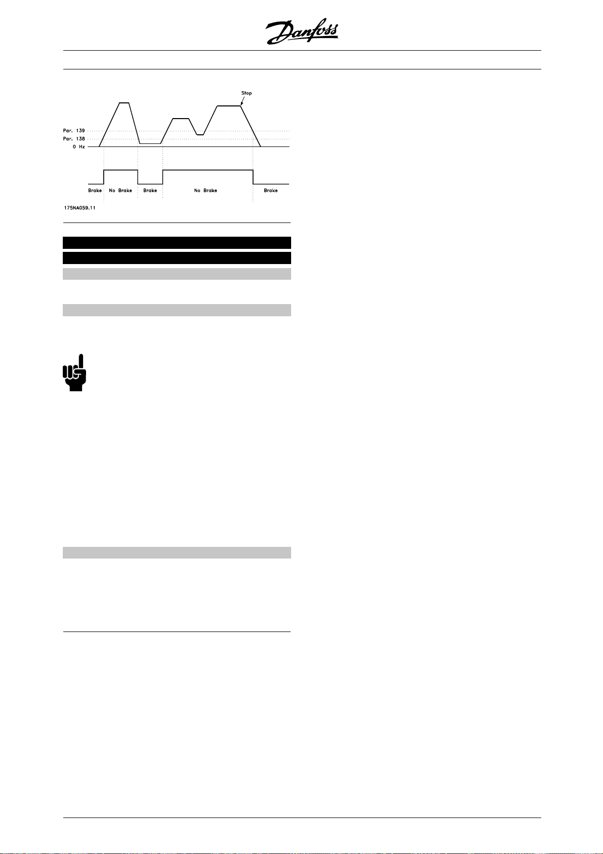
147 Setup of motor type
(SETUP OF MOTOR TYPE)
Value:
Depends on unit
Function:
This is where to select the specific motor at which
the spare part unit is to be installed.
VLT®FCM Series
NB!:
This parameter will only be changeable
in spare part units.
Please check software version number
in parameter 624.
If software version = 2.61:
After changing parameter 147, please set parameter
620 to initialize [3] and power off and on again.
If software version > 2.61:
After changing parameter 147, please switch
power off and on again.
Please note that the actions above will put
the drive into factory settings (except for
parameters 500, and 600-605).
Description of choice:
Select the choice of motor according to motor brand,
numbers of poles and power size.
Example: ATB STD-4-075 means ATB 4
pole 0.75 kW motor.
✭ = factory setting. () = display text [] = value for use in communication via serial communication port
44
MG.03.H3.02 - VLT is a registered Danfoss trademark
Page 45

VLT®FCM Series
200 Rotation direction
(ROTATION)
Value:
✭Only clockwise,
(ONLY CLOCKWISE)
Both directions,
0-132 Hz (132 HZ BOTH DIRECTIONS)
Only counterclockwise, 0-132 Hz
(132HZ COUNTERCLOCKW.)
Function:
This parameter guarantees protection against
unwanted reversing.
Using Process, closed loop mode (parameter
100) parameter 200 must n
ot be changed
to Both directions [1].
Description of choice:
Select the desired direction seen from the
motor drive end.
Note that if Only clockwise, 0-132 Hz [0] /Only
counterclockwise, 0-132 Hz [2] is selected, the output
frequency will be limited to the range f
MIN-fMAX
.
If Both directions, 0-132 Hz [1] is selected, the output
frequency will be limited to the range ± f
MAX
(the
minimum frequency is of no significance).
NB!:
This is only possible in Stop Mode (motor
stopped on a Stop command). Ramp will
be followed, if no set up change.
NB!:
If parameter 200, selection of direction, is set
for different values in the 2 setups, and the
setup is changed during operation, the direction
changes without ramping. In such cases trip may
occur and that may reduce the service life of the power
module, as well as it may be harmful to the application.
Therefore!
It is recommended n
ot to set parameter 200 for
different values in the 2 setups. If that should be
necessary the user must make sure that setup
changes are only made with stopped motor.
[0]
[1]
[2]
Function:
In this parameter, a minimum motor frequency limit
can be selected that corresponds to the minimum
frequency at which the motor is to run.
The minimum frequency can never be higher than
the maximum frequency, f
MAX
.
If Both directions has been selected in parameter 200,
the minimum frequency is of no significance.
Description of choice:
A value from 0.0 Hz to the max. frequency selected
in parameter 202 (f
) can be chosen.
MAX
202 Max. output frequency
(MAX OUTPUT FREQ)
Value:
f
(parameter 201) - f
MIN
✭f
RANGE
(132 Hz, par. 200)
RANGE
Function:
In this parameter, a maximum motor frequency
can be selected that corresponds to the highest
frequency at which the motor is to run.
See also parameter 205.
Description of choice:
Avaluefromf
to 132 Hz can be selected.
MIN
203 Reference/feedback range
(REF/FEEDB. RANGE)
Value:
✭Min - Max (MIN - MAX)
-Max-+Max(-MAX-+MAX)
Function:
This parameter decides whether the reference signal is
to be positive or can be both positive and negative.
NB!:
Analogue input (reference/feedback) can
only be positive.
Programming
[0]
[1]
Choose Min - Max [0] if Process, closed loop mode
has been selected in parameter 100.
201 Min. output frequency
(MIN OUTPUT FREQ)
Value:
0.0 HZ - f
MAX
✭0.0 HZ
(PARAMETER 202)
[0 -]
[0]
Description of choice:
Choose the desired range.
✭ = factory setting. () = display text [] = value for use in communication via serial communication port
MG.03.H3.02 - VLT is a registered Danfoss trademark
45
Page 46

204 Minimum reference
(MIN. REFERENCE)
Value:
-100,000.000 - Ref
(PAR. 205)
MAX
[-100000000 -]
✭0.000
Depends on parameter 100.
Function:
The Minimum reference gives the minimum setting that
can be assumed by the sum of all references.
Minimum reference is only active if Min - Max [0] has
been set in parameter 203; however, it is always active
in Process, closed loop mode (parameter 100).
Description of choice:
Is only active when parameter 203 has been
set to Min - Max [0].
Set the desired value.
205 Maximum reference
(MAX. REFERENCE)
Value:
Ref
(parameter 204)-100,000,000
MIN
✭50.000 HZ
[-100000000]
[50000]
Function:
The Maximum reference gives the highest value
that can be assumed by the sum of all references.
If parameter 100 has been selected to open loop
the max. setting is 132 Hz.
If closed loop has been selected the maximum
reference cannot be set higher than the maximum
feedback (parameter 415).
Description of choice:
Set the desired value.
[0]
VLT®FCM Series
Description of choice:
Program the desired ramp-up time.
208 Ramp-down time 1
(RAMPDOWNTIME1)
Value:
0.15 - 3600.00 sec.
✭3.00 sec.
Function:
The ramp-down time is the deceleration time from
the rated motor frequency f
(parameter 104) to 0
M,N
Hz provided there is no over-voltage in the inverter
because of regenerative operation of the motor, and the
current limit is not reached (to be set in parameter 221).
Description of choice:
Program the desired ramp-down time.
209 Ramp-up time 2
(RAMPUPTIME2)
Value:
0.15 - 3600.00 sec.
✭3.00 sec.
[5 - 360000]
[300]
[5 -360000]
[300]
207 Ramp-up time 1
(RAMPUPTIME1)
Value:
0.15 - 3600.00 sec.
[5 -360000]
3.00 sec.
Function:
The ramp-up time is the acceleration time from 0
Hz to the rated motor frequency f
(parameter
M,N
104). This presupposes that the current limit is not
[300]
Function:
The ramp-up time is the acceleration time from 0
Hz to the rated motor frequency f
104). This presupposes that the current limit is not
reached (to be set in parameter 221).
Description of choice:
Program the desired ramp-up time.
Shift from ramp 1 to ramp 2 by activating
ramp 2 via a digital input.
reached (to be set in parameter 221).
✭ = factory setting. () = display text [] = value for use in communication via serial communication port
46
MG.03.H3.02 - VLT is a registered Danfoss trademark
(parameter
M,N
Page 47

VLT®FCM Series
210 Ramp-down time 2
(RAMPDOWNTIME2)
Value:
0.15 - 3600.00 sec.
✭3.00 sec.
[5 - 360000]
[300]
Function:
The ramp-down time is the deceleration time from
the rated motor frequency f
(parameter 104) to 0
M,N
Hz provided there is no over-voltage in the inverter
because of regenerative operation of the motor, and the
current limit is not reached (to be set in parameter 221).
Description of choice:
Program the desired ramp-down time.
Shift from ramp 1 to ramp 2 by activating
ramp 2 via a digital input
211 Jog ramp time
(JOG RAMP TIME)
Value:
0.15 - 3600.00 sec.
✭3.00 sec.
[5 - 360000]
[300]
Function:
The jog ramp time is the acceleration/deceleration time
from 0 Hz to the rated motor frequency f
(parameter
M,N
104), provided there is no over-voltage in the inverter
because of regenerative operation of the motor, and the
current limit is not reached (to be set in parameter 221).
212 Quick stop ramp-down time
(Q STOP RAMP TIME)
Value:
0.15 - 3600.00 sec.
✭3.00 sec.
[5 - 360000]
[300]
Function:
The ramp-down time is the deceleration time from the
rated motor frequency to 0 Hz, provided there is no
over-voltage in the inverter because of regenerative
operation of the motor, and the current limit is not
reached (to be set in parameter 221).
Quick-stop is activated by means of a signal
on one of the digital input terminals (2-5), or via
the serial communication port.
Description of choice:
Program the desired ramp-down time.
213 Jog frequency
(JOG FREQUENCY)
Value:
0.0 HZ - parameter 202
✭10.0 HZ
[0 -]
[100]
Function:
The jog frequency f
is the fixed output
JOG
frequency at which the FC motor is running when
the jog function is activated.
Programming
Description of choice:
Set the desired frequency.
214 Reference function
(REF FUNCTION )
Value:
✭Sum (SUM)
External/preset (EXTERNAL/PRESET)
Function:
It is possible to define how the preset references
are to be added to the other references. For
this purpose, Sum is used. It is also possible -
The jog ramp time starts if a jog signal is given via the
digital inputs or the serial communication port.
Description of choice:
Set the desired ramp time.
by using the External/preset function - to select
whether a shift between external references and
preset references is desired.
Description of choice:
If Sum [0] is selected, one of the adjusted preset
references (parameters 215-216) is added as a
percentage of the maximum possible reference.
= factory setting. () = display text [] = value for use in communication via serial communication port
✭
[0]
[2]
MG.03.H3.02 - VLT is a registered Danfoss trademark
47
Page 48

VLT®FCM Series
If External/preset [2] is selected, it is possible to shift
between external references or preset references
via terminal 2, 3, 4, or 5 (parameter 332, 333, 334,
or 335). Preset references will be a percentage
value of the reference range.
External reference is the sum of the analogue
references, pulses and bus references.
NB!:
If Sum is selected, one of the preset references
will always be active. If the preset references
are to be without influence, they should be
set to 0 % (as in the factory setting).
215 Preset reference 1
(PRESET REF. 1)
216 Preset reference 2
(PRESET REF. 2)
Value:
-100.00 % - +100.00 %
[-10000 - +10000]
NB!:
The parameter 215-216 setting automatically
will be the setting of parameter 241-242
as well. Parameter 241-247 can be used
for up to 7 preset references.
219 Catch up/slow down value
(CATCH UP/SLW DWN)
Value:
0.00 - 100.00 %
[0 - 10000]
✭0.00 %
Function:
This parameter enables the entry of a percentage
value (relative) which will either be added to or
deducted from the actual reference.
Description of choice:
If Catch up has been selected via one of the
terminals 2, 3, 4, or 5 (parameters 332 - 335), the
percentage (relative) value selected in parameter
219 will be added to the total reference.
[0]
% of the reference range/external reference
0.00%
Function:
Two different preset references can be programmed
in parameters 215-216.
The preset reference is stated as a percentage of
the value Ref
or as a percentage of the other
MAX
external references, depending on the choice made in
parameter 214. If a Ref
≠ 0 has been programmed,
MIN
the preset reference as a percentage will be calculated
on the basis of the difference between Ref
, following the value is added to Ref
Ref
MIN
MAX
MIN
and
.
Description of choice:
Set the fixed reference(s) that is/are to be the options.
To use the fixed references, it is necessary to
have selected Preset ref. enable on terminal 2,
3, 4, or 5 (parameters 332 - 335).
Choices between fixed references can be made by
activating terminal 2, 3, 4, or 5 - see the table be
low.
[0]
If Slow down has been selected via one of the
terminals 2, 3, 4, or 5 (parameters 332 - 335), the
percentage (relative) value selected in parameter 219
will be deducted from the total reference.
221 Current limit for motor mode
(CURRENT L IMIT)
Value:
Min. limit (XX.X) - max. limit (XXX.X)
in % of I
RATED
✭Max. limit (XXX.X)
= rated motor current
I
RATED
Min. limit = magnetising current in % of I
Max. limit = unit dependent limit in % of I
[XXX - XXXX]
[XXXX]
RATED
RATED
Function:
This function is relevant for all application configurations;
speed and process regulation. This is where to set
the current limit for motor operation.
Terminals 2/3/4/5
Preset reference
Preset reference 1 0
Preset reference 2 1
= factory setting. () = display text [] = value for use in communication via serial communication port
✭
48
MG.03.H3.02 - VLT is a registered Danfoss trademark
Page 49

VLT®FCM Series
A percentage of the setting in parameters
230-231 is selected.
230 Frequency bypass 1
(FREQ. BYPASS 1)
231 Frequency bypass 2
(FREQ. BYPASS 2)
Value:
0.0 - 132 Hz (PARAMETER 200)
✭0.0 Hz
Function:
Some systems call for some output frequencies to be
avoided because of resonance problems in the system.
Description of choice:
Enter the frequencies to be avoided.
[0 -]
[0]
Description of choice:
Set the desired % of current.
NB!:
The setting is limited to 160%, but for motors
with2poles(0.55+1.1kW),thesettingis
limited to 120% which corresponds to 160%
torque, setting 73% corresponds to 100% torque.
229 Frequency bypass, bandwidth
(FREQ BYPASS B.W.)
Value:
0(OFF)-100%
[0-100]
0 (OFF) %
[0]
See also parameter 229.
241 Reference preset 1
(REF PRESET 1)
242 Reference preset 2
(REF PRESET 2)
243 Reference preset 3
(REF PRESET 3)
244 Reference preset 4
(REF PRESET 4)
245 Reference preset 5
(REF PRESET 5)
246 Reference preset 6
(REF PRESET 6)
247 Reference preset 7
(REF PRESET 7)
Value:
-100.00 % - +100.00 %
Programming
[-10000 - +10000]
Function:
Some systems call for some output frequencies to be
% of the reference range/external reference
✭0.00%
avoided because of resonance problems in the system.
In parameters 230-231 these output frequencies can
be programmed for bypassing (Frequency bypass).
In this parameter (229), a bandwidth can be defined
on either side of these frequency bypasses.
Description of choice:
The bypass band is the bypass frequency +/half the set bandwidth.
= factory setting. () = display text [] = value for use in communication via serial communication port
✭
MG.03.H3.02 - VLT is a registered Danfoss trademark
Function:
Seven different reference presets can be programmed
in parameters 241 - 247 reference preset. The
reference preset is stated as a percentage of the
value Ref
or as a percentage of the other external
MAX
references, depending on the choice made in
parameter 214. If a Ref
MIN
the reference preset as a percentage will be calculated
[0]
≠ 0 has been programmed,
49
Page 50

VLT®FCM Series
on the basis of the difference between Ref
following the value is added to Ref
Ref
MIN
MAX
MIN
and
.
Thechoicebetweenreferencepresetscanbemade
via the digital inputs or via serial communication.
Description of choice:
Set the fixed reference(s) that is/are to be the option.
See P332, P333, P334 and P335 Description of choice,
where the description of the digital input set up is given.
✭ = factory setting. () = display text [] = value for use in communication via serial communication port
50
MG.03.H3.02 - VLT is a registered Danfoss trademark
Page 51

VLT®FCM Series
317 Time out
(LIVE ZERO TIME OUT)
Value:
1-99sec.
✭10 sec.
Function:
If the value of the reference signal connected to
the input, terminal 1, falls below 50% of the setting
in parameter 336 for a period longer than the
time set in parameter 317, the function selected
in parameter 318 will be activated.
Description of choice:
Set the desired time.
[1 - 99]
[10]
323 Terminal X102, relay function (RELAY FUNC.)
Settings:
✭No function (NO OPERATION) [0]
Ready signal (UNIT READY) [1]
Enable, no warning (ENABLE/NO WARNING) [2]
Running (MOTOR RUNNING) [3]
Running, no warning (RUNNING NO WARNING) [4]
Running on reference, no warning (RUNNING ON REFERENCE) [5]
Fault (FAULT) [6]
Fault or warning (FAULT OR WARNING) [7]
Current limit (CURRENT LIMIT) [8]
Thermal warning (THERMAL WARNING) [9]
Reversing (REVERSE) [10]
Control word bit 11 (CONTROL WORD BIT 11) [11]
Control word bit 12 (CONTROL WORD BIT 12) [12]
Mechanical brake (MECHANICAL BRAKE) [20]
318 Function after time out
(LIVE ZERO FUNCT.)
Value:
✭Off (OFF)
Stop and trip (STOP AND TRIP)
Function:
This parameter allows a choice of the function to
be activated if the value of the reference signal
connected to the input, terminal 1, falls below 50%
of the setting in parameter 336 for a period longer
than the time set in parameter 317.
If a time-out function (parameter 318) occurs at the
same time as a bus time-out function (parameter 514),
the time-out function (parameter 318) will be activated.
[0]
[5]
Programming
Therelayoutputcanbeusedtogivethe
present status or a warning.
Relay
1-3break,1-2make
Max. 250 V AC, 5Amp.
Description of choice:
Unit Ready signal, the FC motor is ready for use.
Enable/no warning, the FC motor is ready for
use; no start or stop command has been given
(start/ disable). No warning.
Motor Running, the output frequency is higher than
0.1 Hz. A start command has been given.
= factory setting. () = display text [] = value for use in communication via serial communication port
✭
MG.03.H3.02 - VLT is a registered Danfoss trademark
Running no warning, the output frequency is higher than
0.1 Hz. A start command has been given. No warning.
Running on reference, no warning, speed according
to reference. No warning.
Fault, output is activated by alarm.
Fault or warning, the output is activated by
alarm or warning.
Current limit, the current limit in parameter
221 has been exceeded.
Thermal warning, above the temperature limit
in the frequency converter.
51
Page 52

VLT®FCM Series
Reverse. Logic ’1’ = relay activated, 24 V DC on the
output when the direction of rotation of the motor
is clockwise. Logic ’0’ = relay not activated, no
signal on the output, when the direction of rotation
of the motor is counter-clockwise.
Control word bit 11, if bit 11 = "1" in the control
word (both Fieldbus Profile and FC Profile)
the relay will be activated.
Control word bit 12, if bit 12 = "1" in the control
word (both Fieldbus Profile and FC Profile)
the relay will be activated.
Mechanical brake, enables control of an
optional external mechanical brake (see also
parameter 138 and 139).
327 Pulse reference/feedback, max. frequency
(PULSE REF/FB MAX)
Value:
100 - 70000 Hz
✭5000 HZ
[100 - 70000]
[5000]
Description of choice:
No operation. Is selected if the FC motor is not to
react to signals connected to the terminal.
Reference. Is selected to enable change of reference
by means of an analogue reference signal.
If other inputs are connected, these are added
up, taking account of their signs.
Feedback. Is selected if closed loop regulation
with an analogue signal is used.
NB!:
If Reference or Feedback has been
selected on more than one terminal, these
signals will be added.
Function:
In this parameter, the signal value is set that
corresponds to the maximum reference/feedback
value set in parameter 205/415.
Description of choice:
Set the desired pulse frequency.
NB!:
Frequency limit:
Open collector 24 V: 8 kHz
Push pull 24 V: 70 kHz
331 Terminal 1, analogue input current
(AI [MA] 1 FUNCT)
Value:
✭No operation (NO OPERATION)
Reference (REFERENCE)
Feedback (FEEDBACK)
Function:
This parameter allows a choice between the different
functions available for the input, terminal 1.
[0]
[1]
[2]
Scaling of the input signal is effected in
parameters 338 and 339.
✭ = factory setting. () = display text [] = value for use in communication via serial communication port
52
MG.03.H3.02 - VLT is a registered Danfoss trademark
Page 53

VLT®FCM Series
332 Terminal 2, analogue/digital input
(DIGITAL INPUT 2)
333 Terminal 3, digital input
(DIGITAL INPUT 3)
334 Terminal 4, digital input
(DIGITAL INPUT 4)
335 Terminal 5, digital input
(DIGITAL INPUT 5)
Parameter 332 333 334 335
Digital input on terminal no. 2 3 4 5
Settings:
No function (NO OPERATION) [0] [0] [0] [0]
Reset (RESET) [1] ✭[1] [1] [1]
Coasting stop, inverse (MOTOR COAST INVERSE) [2] [2] [2] [2]
Reset and coasting stop, inverse (RESET & COAST INV.) [3] [3] [3] [3]
Quick-stop, inverse (QUICK STOP INVERSE) [4] [4] [4] [4]
DC-braking, inverse (DC-BRAKE INVERSE) [5] [5] [5] [5]
Stop inverse (STOP INVERSE) [6] [6] [6] [6]
Start (START) [7] [7] ✭[7] [7]
Latched start (LATCHED START) [8] [8] [8] [8]
Reversing (REVERSING) [9] [9] [9] [9]
Start reversing (START REVERSING) [10] [10] [10] [10]
Start clockwise, on (ENABLE FORWARD) [11] [11] [11] [11]
Start counter-clockwise, on (ENABLE REVERSE) [12] [12] [12] [12]
Jog (JOGGING) [13] [13] [13] ✭[13]
Freeze reference (FREEZE REFERENCE) [14] [14] [14] [14]
Freeze output (FREEZE OUTPUT) [15] [15] [15] [15]
Speed up (SPEED UP) [16] [16] [16] [16]
Speed down (SPEED DOWN) [17] [17] [17] [17]
Selection of Setup (SETUP SELECT) [18] [18] [18] [18]
Catch-up (CATCH UP) [19] [19] [19] [19]
Slow-down (SLOW DOWN) [20] [20] [20] [20]
Preset reference (PRESET REF.) [21] [21] [21] [21]
Preset reference, on (PRESET REF. ON) [22] [22] [22] [22]
Precise stop, inverse (PRECISE STOP) [23]
Pulse reference (PULSE REFERENCE) [24]
Pulse feedback (PULSE FEEDBACK) [25]
Analogue reference (REFERENCE) ✭[30]
Analogue feedback (FEEDBACK) [31]
Reset and start (RESET AND START) [32] [32] [32] [32]
Freeze reference and start (FREEZE REF AND START) [33] [33] [33] [33]
Ramp 2 (RAMP 2) [34] [34] [34] [34]
Start-ref bit 1 (START-REF BIT 1) [35] [35] [35] [35]
Start-ref bit 2 (START-REF BIT 2) [36] [36] [36] [36]
Start-ref bit 3 (START-REF BIT 3) [37] [37] [37] [37]
Programming
Function:
In parameters 332-335 it is possible to choose
between the different possible functions related to
the inputs on terminals 2-5. The function options
areshowninthetablebelow.
= factory setting. () = display text [] = value for use in communication via serial communication port
✭
MG.03.H3.02 - VLT is a registered Danfoss trademark
Description of choice:
No funct ion is selected if the FC motor is not to
react to signals transmitted to the terminal.
53
Page 54

VLT®FCM Series
Reset zeroes the FC motor after an alarm;
however, not all alarms can be reset without
disconnecting from mains.
Coasting stop, inverse is used for making the FC motor
run freely to stop. Logic ’0’ leadstocoastingstop.
Reset and coasting stop, inverse, is used for activating
coasting stop at the same time as reset.
Logic ‘0’ leadstocoastingstopandreset.
Quick stop, inverse is used for stopping the
motor in accordance with the quick-stop ramp
(set in parameter 212).
Logic ’0’ leads to a quick-stop.
DC breaking, inverse is used for stopping the
motor by energizing it with a DC voltage for a
given time, see parameters 126-132.
Please note that this function is only active if the
settings of parameters 126-132 is different from
0. Logic ’0’ leads to DC braking.
Stop inverse is activated by interrupting the voltage
to the terminal. This means that if the terminal
has no voltage, the motor cannot run. The stop
will be effected in accordance with the selected
ramp (parameters 207/208).
None of the above-mentioned stop
commands are to be used as
disconnection switch in connection
with repairs. Cut mains instead.
Start clockwise is used if the motor shaft is only to
be able to rotate clockwise when starting.
Should not be used with Process, closed loop mode.
Start counter-clockwise, on is used if the motor shaft is
to be able to rotate counter-clockwise when started.
Should not be used with Process, closed loop mode.
Jog is used for overriding the output frequency to the
jog frequency set in parameter 213. The ramp time
can be set in parameter 211. Jog is not active if a
stop command has been given (start-disable).
Jog overrides stand-by.
Freeze reference - freezes the actual reference. The
frozen reference is now the point of enable/ condition
for Speed up and Speed down to be used.
If speed up/down is used, the speed change
always follows the normal ramp (parameters
207/208) in the range 0 - Ref
MAX
.
Freeze output - freezes the actual motor frequency
(Hz). The frozen motor frequency is now the
point of enable/condition for Speed up and
Speed down to be used.
Freeze output overrides start/stand-by, slip
compensation and closed loop process control.
If speed up/down is used, the speed change
always follows the normal ramp (parameters
207/208) in the range 0 - f
M,N
.
Start, is selected if a start/stop command is desired.
Logic ’1’ = start, logic ’0’ = stop (stand-by).
Latched start - if a pulse is applied for min. 20 ms,
the motor will start, provided no stop command. The
motor stops if Stop inverse is activated briefly.
Reversing is used for changing the direction of
rotation of the motor shaft. Logic "0" will not lead
to reversing. Logic "1" will lead to reversing. The
reversing signal only changes the direction of rotation;
it does not activate the start function.
Should not be used with Process, closed loop mode.
Start reversing, is used for start/stop and for reversing
Speed up and Speed down are selected if digital
control of the up/down speed is desired (motor
potentiometer). This function is only active if Freeze
reference or Freeze output has been selected.
As long as there is a logic ‘1‘ on the terminal
selected for speed up, the reference or the
output frequency will increase.
As long as there is a logic ‘1‘ on the terminal
selected for speed down, the reference or the
output frequency will be reduced.
Pulses (logic ‘1‘ minimum high for 20 ms and a
minimum pause of 20 ms) will lead to a change of
speed of 0.1% (reference) or 0.1 Hz (output frequency).
with the same signal. No start signal is allowed at the
same time. Acts as latch start reversing, provided latch
start has been chosen for another terminal.
Should not be used with Process, closed loop mode.
= factory setting. () = display text [] = value for use in communication via serial communication port
✭
54
MG.03.H3.02 - VLT is a registered Danfoss trademark
Page 55

VLT®FCM Series
Example:
Ter min al F re ez e r ef ./
2-5 2-5 Freeze output
No speed change 0 0 1
Speed down 0 1 1
Speed up 1 0 1
Speed down 1 1 1
Selection of Setup, enables a choice of one of
the two Setups; however, this presupposes that
parameter 004 has been set to Multi Setup.
Catch-up/Slow-down is selected if the reference value
is to be increased or reduced by a programmable
percentage value set in parameter 219.
Slow-down Catch-up
Unchanged speed 0 0
Reduced by %-value 1 0
Increased by %-value 0 1
Reduced by %-value 1 1
Preset reference enables a choice of one of the
two preset references, in accordance with the table
in parameter 215 and 216. To be active, Preset
reference, on has to be selected.
Preset reference is used for shifting between external
reference and preset reference. It is assumed that
External/preset [2] has been selected in parameter
214. Logic ’0’ = external references active; logic ’1’
= one of the two preset references is active.
Precise stop corrects the ramp-down time to obtain
a high repetitive accuracy of the stopping point.
Pulse reference is selected if a pulse sequence
(frequency) of 0 Hz is used, corresponding to Ref
parameter 204. The frequency is set in parameter
327, corresponding to Ref
Pulse feedback is selected if a pulse sequence
(frequency) is selected as a feedback signal.
See also parameter 327.
MAX
.
MIN
Freeze refere nce and start, both a START and a
FREEZE REFERENCE command will be initiated.
When using SPEED UP/SPEED DOWN both FREEZE
REFERENCE and START must be activated. By
implementing this feature a digital input can be spared.
Ramp 2, is selected if a shift between ramp 1
(parameters 207-208) and ramp 2 (parameters
209-210) is required. Logic "0" leads to ramp
1 and logic "1" leads to ramp 2.
Start-ref bit 1,2 and 3, makes it possible to select
which REF RESET (1-7) is to be used. The REF
PRESET (1-7) are set in parameters 241 to 247.
Par. No Fixed speed START REF BIT
321
- - - Stand by 000
241 REF RESET 1 001
242 REF RESET 2 010
243 REF RESET 3 011
244 REF RESET 4 100
245 REF RESET 5 101
246 REF RESET 6 110
247 REF RESET 7 111
If at least one of the 3 digital inputs is activated the FCM
has start signal. The 7 possible input combinations will
than decide which preset speed is to be used.
If only 1 or 2 digital inputs are used respectively 1 or 3
speeds can be chosen after above shown principle.
If 2 set-ups are used up to 14 preset speeds can be
chosen by means of 4 digital inputs. The P241 and
P242 settings will be mirrored into P215 and P216.
Ex.
,
Digital inputs 2,3 and 4: P332 [choice 35
selected], P333 [choice 36 selected] and P334
[choice 37 selected]
Input combination on the digital inputs 2,3 and 4: "010".
This means REF PRESET 2 will be the preset speed.
Scaling of the input signal is effected in
parameters 338 and 339.
Programming
Analogue reference is selected to enable change of
reference by means of an analogue reference signal.
If other inputs are connected, these are added
up, taking account of their signs.
Analogue feedback is selected if closed loop regulation
with an analogue signal is used.
Reset and start is used for activating start at
the same time as reset.
✭
= factory setting. () = display text [] = value for use in communication via serial communication port
MG.03.H3.02 - VLT is a registered Danfoss trademark
NB!:
If Reference or Feedback has been selected
on more than one terminal, these signals
will be added with signs.
336 Terminal 1, min. scaling
(AI 1 SCALE LOW)
Value:
0.0 - 20.0 mA
✭0.0 mA
[0 - 200]
[0]
55
Page 56

VLT®FCM Series
Function:
This parameter determines the value of the reference
signal that is to correspond to the minimum
reference value set in parameter 204.
If the Time-out function of parameter 317 is to be
used, the setting must be > 2 mA.
Description of choice:
Set the desired current value.
337 Terminal 1, max. scaling
(AI 1 SCALE HIGH)
Value:
0.0 - 20.0 mA
✭20.0 mA
[0 - 200]
[200]
Function:
This parameter sets the value of the reference
signal that is to correspond to the maximum
reference value set in parameter 205.
Function:
This parameter is used for setting the signal value
that is to correspond to the maximum reference value
or maximum feedback, parameter 205 Maximum
reference, Ref
/ 415 Maximum feedback, FB
MAX
MAX
Description of choice:
Set the required voltage value. For reasons of
accuracy, compensation should be made for
voltage losses in long signal cables.
.
Description of choice:
Set the desired current value.
338 Terminal 2, min. scaling
(AI 2 SCALE LOW)
Value:
0.0 - 10.0 V
[0 - 100]
✭0.0 V
Function:
This parameter is used for setting the signal value
that is to correspond to the minimum reference or
the minimum feedback, parameter 204 Minimum
reference, Ref
/ 414 Minimum feedback, FB
MIN
MIN
.
Description of choice:
Set the required voltage value. For reasons of accuracy,
compensation should be made for voltage loss in long
signal cables. If the Time out function is to be used
(parameter 317 Time out and 318 Function after time
out), the value set must be higher than 1 Volt.
[0]
339 Terminal 2, max. scaling
(AI 2 SCALE HIGH)
Value:
0.0 - 10.0 V0.0 - 10.0 V
✭10.0 V
[0 - 100]
[100]
✭ = factory setting. () = display text [] = value for use in communication via serial communication port
56
MG.03.H3.02 - VLT is a registered Danfoss trademark
Page 57

VLT®FCM Series
340 Terminal 9, output functions (OUTPUT FUNC.)
Settings:
✭No function (NO OPERATION) [0]
Ready signal (UNIT READY) [1]
Enable, no warning (ENABLE/NO WARNING) [2]
Running (MOTOR RUNNING) [3]
Running, no warning (RUNNING NO WARNING) [4]
Running on reference, no warning (RUNNING ON REFERENCE) [5]
Fault (FAULT) [6]
Fault or warning (FAULT OR WARNING) [7]
Current limit (CURRENT LIMIT) [8]
Thermal warning (THERMAL WARNING) [9]
Reversing (REVERSE) [10]
Control word bit 11 (CONTROL WORD BIT 11) [11]
Actual frequency 0-20 mA (0-FMAX = 0-20 mA) [12]
Actual frequency 4-20 mA (0-FMAX = 4-20 mA) [13]
Reference
Reference
Feedback
Feedback
Actual current 0-20 mA (0-IMAX = 0-20 mA) [18]
Actual current 4-20 mA (0-IMAX = 4-20 mA) [19]
Mechanical brake (MECHANICAL BRAKE) [20]
Sleep mode (SLEEP MODE) [21]
- reference
MIN
- reference
MIN
- feedback
MIN
- feedback
MIN
: 0-20 mA (REF MIN-MAX =0-20 mA) [14]
MAX
: 4-20 mA (REF MIN-MAX =4-20 mA) [15]
MAX
: 0-20 mA (FB MIN-MAX =0-20 mA) [16]
MAX
: 4-20 mA (FB MIN-MAX =4-20 mA) [17]
MAX
Function:
This output can act both as a digital and an
analogue output. If used as a digital output (data
value [0]-[20]), a 24 V DC signal is transmitted;
if used as an analogue output either a 0-20 mA
signal, or a 4-20 mA signal output.
Description of choice:
Unit Ready signal, the FC motor is ready for use.
Enable/no warning, the FC motor is ready for
use; no start or stop command has been given
(start/ disable). No warning.
Motor Running, the output frequency is higher than
0.1 Hz or a start command has been given.
Running no warning, the output frequency is higher than
0.1 Hz. A start command has been given. No warning.
Running on reference, no warning, speed according
to reference. No warning.
Fault, output is activated by alarm.
Fault or warning, the output is activated by
alarm or warning.
Current limit, the current limit in parameter
221 has been exceeded.
Reverse.Logic’1’ = relay activated, 24 V DC on the
output when the direction of rotation of the motor
is clockwise. Logic ’0’ = relay not activated, no
signal on the output, when the direction of rotation
of the motor is counter-clockwise.
Control word bit 11, if bit 11 = "1" in the control
word (both Fieldbus Profile and FC Profile) the
digital output will be activated.
⇒
0-fMAX (parameter 202)
0-fMAX (parameter 202)
Reference
Reference
Feedback
Feedback
0-I
VLT, MAX
0-I
VLT, MAX
- Reference
MIN
- Reference
MIN
- Feedback
LOW
- Feedback
LOW
⇒
0-20 mA and
⇒
4-20 mA
0-20 mA and
⇒
4-20 mA
:0-20mAand
MAX
:4-20mA
MAX
:0-20mAand
HIGH
:4-20mA
HIGH
Mechanical brake, enables control of an
optional external mechanical brake (see also
parameter 138 and 139).
Sleep mode, active when the unit is in sleep
mode. See sectionSleep mode.
Programming
Thermal warning, above the temperature limit
in the frequency converter.
✭ = factory setting. () = display text [] = value for use in communication via serial communication port
MG.03.H3.02 - VLT is a registered Danfoss trademark
57
Page 58

VLT®FCM Series
400 Brake functions
(BRAKE FUNCTIONS)
Value:
OFF (OFF)
AC brake (AC BRAKE)
Function:
AC brake [4] can be selected to improve braking. With
the new AC brake function it is possible to control
the time of increased motor losses, still protecting
the motor thermally. This function will yield a braking
torque between 80 and 20 % in the speed range
up to base speed (50 Hz). Above base speed the
extra braking will gradually disappear.
[0]
[4]
is set that determines how long the output frequency
can be lower than the frequency set in parameter
404 Sleep frequency. When the timer runs out, the
frequency converter will ramp down the motor to stop
via parameter 208 Ramp-down time. If the output
frequency rises above the frequency set in parameter
404 Sleep frequency, the timer is reset.
Description of choice:
Select AC brake [4] if short-term generated loads occur.
■Sleep mode
Sleep mode makes it possible to stop the motor
when it is running at low speed, similar to a no
load situation. If consumption in the system goes
back up, the frequency converter will start the
motor and supply the power required.
NB!:
Energy can be saved with this function,
since the motor is only in operation when
the system needs it.
Sleep mode is not active if Local refe ren ce
or Jog has been selected
The function is active in both Open loop
and Closed loop.
In parameter 403 Sleep mode timer, the Sleep mode is
activated. In parameter 403 Sleep mode timer,atimer
= factory setting. () = display text [] = value for use in communication via serial communication port
✭
58
MG.03.H3.02 - VLT is a registered Danfoss trademark
Page 59

While the frequency converter has stopped the
motor in sleep mode, a theoretical output frequency
is calculated on the basis of the reference signal.
When the theoretical output frequency rises above
the frequency in parameter 407 Wake up frequency,
the frequency converter will restart the motor and the
output frequency will ramp up to the reference.
In systems with constant pressure regulation, it
is advantageous to provide extra pressure to the
system before the frequency converter stops the
motor. This extends the time during which the
VLT®FCM Series
frequency converter has stopped the motor and
helps to avoid frequent starting and stopping of the
motor, e.g. in the case of system leaks.
If 25% more pressure is required before the
frequency converter stops the motor, parameter
406 Boost setpoint is set to 125%.
Parameter 406 Boost setpoint is only active
in Closed loop.
NB!:
In highly dynamic pumping processes, it
is recommended to switch off the Flying
Start function (parameter 445).
Programming
✭ = factory setting. () = display text [] = value for use in communication via serial communication port
MG.03.H3.02 - VLT is a registered Danfoss trademark
59
Page 60

VLT®FCM Series
403 Sleep mode timer
(SLEEP MODE TIMER)
Value:
0 - 300 sec. (301 sec. = OFF)
✭ OFF
Function:
This parameter enables the frequency converter to
stop the motor if the load on the motor is minimal.
The timer in parameter 403 Sleep mode timer starts
when the output frequency drops below the frequency
set in parameter 404 Sleep frequency.
Whenthetimesetinthetimerhasexpired,the
frequency converter will turn off the motor.
The frequency converter will restart the motor, when
the theoretical output frequency exceeds the frequency
in parameter 407 W ake up frequency.
Description of choice:
Select OFF if this function is not wanted. Set
the threshold value that is to activate Sleep
mode after the output frequency has fallen below
parameter 404 Sleep frequency.
Reset at power-up (RESET AT POWER UP)
[11]
Function:
This parameter makes it possible to select the
reset function desired after tripping.
After reset, the FC motor can be restarted after 1.5 sec.
Description of choice:
If Manual reset [0] is selected, reset must be
effected via the digital inputs.
If the FC motor is to carry out an automatic
reset (max. 1-10 times within 10 minutes) after
tripping, select data value [1]-[10].
Warning: The motor may start without
warning up to 10 x 5 sec. after trip.
406 Boost setpoint
(BOOST SETPOINT)
Value:
1-200%
✭ 100 % of setpoint
404 Sleep frequency
(SLEEP FREQUENCY)
Value:
000,0 - par. 407 Wake up frequency
✭ 0,0 Hz
Function:
When the output frequency falls below the preset value,
the timer will start the time count set in parameter 403
Sleep mode. The present output frequency will follow
the theoretical output frequency until f
is reached.
MIN
Description of choice:
Set the required frequency.
405 Reset function
(RESET MODE)
Value:
✭Manual reset (MANUAL RESET)
Automatic reset x 1 (AUTOMATIC X 1)
Automatic reset x 2 (AUTOMATIC X 2)
Automatic reset x 3 (AUTOMATIC X 3)
Automatic reset x 4 (AUTOMATIC X 4)
Automatic reset x 5 (AUTOMATIC X 5)
Automatic reset x 6 (AUTOMATIC X 6)
Automatic reset x 7 (AUTOMATIC X 7)
Automatic reset x 8 (AUTOMATIC X 8)
Automatic reset x 9 (AUTOMATIC X 9)
Automatic reset x 10 (AUTOMATIC X 10)
[10]
[0]
[1]
[2]
[3]
[4]
[5]
[6]
[7]
[8]
[9]
Function:
This function can only be used if Closed loop has
been selected in parameter 100.
In systems with constant pressure regulation, it is
advantageous to increase the pressure in the system
before the frequency converter stops the motor.
This extends the time during which the frequency
converter stops the motor and helps to avoid frequent
starting and stopping of the motor, e.g. in the case
of leaks in the water supply system.
Description of choice:
Set the required Boost setpoint as a percentage
of the resulting reference under normal operation.
100% corresponds to the reference without
boost (supplement).
407 Wake up frequency
(WAKEUP FREQUENCY)
Value:
Par 404 Sleep frequency - par. 202 f
MAX
✭ 50 Hz
Function:
When the theoretical output frequency exceeds the
preset value, the frequency converter restarts the motor.
= factory setting. () = display text [] = value for use in communication via serial communication port
✭
60
MG.03.H3.02 - VLT is a registered Danfoss trademark
Page 61

VLT®FCM Series
Description of choice:
Set the required frequency.
411 Switching frequency
(SWITCH FREQ .)
Value:
1.5 -14.0 kHz
[1500 - 14000]
✭Unit dependent
Function:
The setting determines the switching frequency of the
inverter. If the switching frequency is changed, this may
help to minimise possible acoustic noise from the motor.
Description of choice:
When the motor is running, the switching frequency is
adjusted in parameter 411 until the frequency has been
obtained at which the motor is as low-noise as possible.
See also parameter 446 - switching pattern.
See derating in chapter 10.
NB!:
Switching frequencies higher than 4 kHz
may cause thermal trip depending on
ambient temperature.
412 Variable switching frequency
(VAR CARRIER FREQ)
Value:
Not possible (DISABLE)
Variable switching freq. (VAR. CARRIER FREQ.)
✭Temperature dep. sw. freq. (TEMP. DEP. FREQ.)
Function:
This function makes it possible to change the
switching frequency depending on the load. However,
the maximum switching frequency is determined
by the value set in parameter 411.
Description of choice:
Select Not possible [0] if a permanent switching
frequency is desired. Set the switching
frequency in parameter 411.
If Varia b le switching frequency [1] is selected the
switching frequency will decline at an increasing
output frequency. This is used in applications
with square torque characteristics (centrifugal
pumps and fans) in which the load declines
depending on the output frequency.
[0]
[1]
[2]
If Temperature dependent switching frequency [2] is
selected, the switching frequency will decline at an
increasing inverter temperature, see the drawing below.
413 Overmodulation function
(OVERMODULATION)
Value:
Off (OFF)
✭On (ON)
Function:
This parameter allows connection of the
overmodulation function for the output voltage.
Description of choice:
Off means that there is no overmodulation of the
output voltage, which means that torque ripple on
the motor shaft is avoided. This can be a good
feature, e.g. on grinding machines.
On means that an output voltage can be obtained
which is greater than the mains voltage (up to 5%).
414 Minimum feedback
(MIN. FEEDBACK)
Value:
-100,000,000 - FB
HIGH
(PAR. 415)
[-100000000 -]
✭0.000
Function:
Parameters 414 and 415 are used to scale the
feedback range to physical values used by the
user. The setting will also be the bounds of the
reference (parameters 204 and 205).
[0]
[1]
Programming
[0]
= factory setting. () = display text [] = value for use in communication via serial communication port
✭
MG.03.H3.02 - VLT is a registered Danfoss trademark
61
Page 62

VLT®FCM Series
Used together with Process, closed loop
mode (parameter 100).
Description of choice:
Is only active when parameter 203 has been
set to Min-Max [0].
415 Maximum feedback
(MAX. FEEDBACK)
Value:
(par. 414) FB
- 100,000,000
LOW
[- 100000000]
✭1.500.000
Function:
See description of parameter 414.
416 Reference/feedback unit
(REF/FEEDB. UNIT)
Value:
NO UNIT
✭%
PPM
RPM
bar
CYCLE/min
PULSE/s
UNITS/s
UNITS/min
UNITS/h
°C
Pa
l/s
3
/s
m
l/min
3
/min
m
l/h
3
/h
m
kg/s
kg/min
kg/h
t/min
t/h
m
Nm
m/s
m/min
°F
in wg
gal/s
3
/s
ft
[1500000]
[0]
[1]
[2]
[3]
[4]
[5]
[6]
[7]
[8]
[9]
[10]
[11]
[12]
[13]
[14]
[15]
[16]
[17]
[18]
[19]
[20]
[21]
[22]
[23]
[24]
[25]
[26]
[27]
[28]
[29]
[30]
gal/min
3
/min
ft
gal/h
3
/h
ft
lb/s
lb/min
lb/h
lb ft
ft/s
ft/min
[31]
[32]
[33]
[34]
[35]
[36]
[37]
[38]
[39]
[40]
Function:
Choose among different units to be shown
on the display.
This unit is also used directly in Process regulation,
closed loop as a unit for Minimum/Maximum reference
(parameters 204/205) and Minimum/ Maximum
feedback (parameters 414/415).
The possibility of choosing a unit in parameter
416 will depend on the choices made in the
following parameters:
Par. 002 Local/remote control.
Par. 013 Local control/config. as par. 100.
Par. 100 Configuration.
elect parameter 002 as Remote control
S
If parameter 100 is selected as Speed regulation,
open loop, the unit selected in parameter 416
can be used in displays (par. 009-12 Feedback
[unit]) of process parameters.
Note: The reference can only be shown in Hz
(Speed regulation, open loop).
If parameter 100 is selected as Process regulation,
closed loop, the unit selected in parameter 416
will be used when displaying both reference
(par. 009- 12: Reference [unit]) and feedback
(par. 009-12: Feedback [unit]).
elect parameter 002 as Local control
S
If parameter 013 is chosen as LCP control and
open loop or LCP digital control and open loop ,
the reference will be given in Hz, regardless of the
choice made in parameter 416. If parameter 013 is
chosen as LCP control/as par. 100 or LCP digital
control/as par. 100, the unit will be as described
above under parameter 002, Remote-control.
NB!:
The above applies to display of Reference
[unit] and Feedback [unit].IfReference [%] or
Feedback [%] is selected, the value displayed
will be in the form of a percentage of the selected range.
= factory setting. () = display text [] = value for use in communication via serial communication port
✭
62
MG.03.H3.02 - VLT is a registered Danfoss trademark
Page 63

VLT®FCM Series
Description of choice:
Select the desired unit for the reference/feedback signal.
■FCM 300 Regulator
rocess regulation
P
The PID regulator maintains a constant process
mode (pressure, temperature, flow, etc.) and
adjusts the motor speed on the basis of the
reference/setpoint and feedback signal.
A transmitter provides the PID regulator with a
feedback signal from the process as an expression
of the process’s actual mode. The feedback signal
varies as the process load varies.
This means that there is a variance between the
reference/setpoint and the actual process mode.
This variance is compensated by the PID regulator
by means of the output frequency being regulated
up or down in relation to the variance between the
reference/setpoint and the feedback signal.
The integrated PID regulator in the frequency converter
has been optimised for use in process applications.
This means that there are a number of special functions
available in the frequency converter.
Previously it was necessary to obtain a system to
handle these special functions by installing extra I/O
modules and programming the system. With the
frequency converter the need to install extra modules
can be avoided. The parameters that are specific to the
Process Regulator are parameter 437 to parameter 444.
■PID functions
nit of reference/feedback
U
When Process regulation, closed loop is selected
in parameter 100 Configuration the unit is defined
in parameter 416 Reference/feedback unit:
eedback
F
A feedback range must be preset for the regulator. At
the same time this feedback range limits the potential
reference range so that if the sum of all references
lies outside the feedback range, the reference will
be limited to lie within the feedback range.
The feedback signal must be connected to a
terminal on the frequency converter. If feedback
is selected on two terminals simultaneously, the
two signals will be added together.
Use the overview below to determine which terminal is to
be used and which parameters are to be programmed.
Feedback type Terminal Parameters
Pulse 3 333, 327
Voltage 2 332, 338, 339
Current 1 331, 336, 337
A correction can be made for loss of voltage
in long signal cables when a transmitter with a
voltage output is used. This is done in parameters
338/339 Min./Max s caling.
Parameters 414/415 Minimum/Maximum feedback
must also be preset to a value in the process unit
corresponding to the minimum and maximum scaling
values for signals that are connected to the terminal.
eference
R
In parameter 205 Maximum reference, Ref
possible to preset a maximum reference that scales the
sum of all references, i.e. the resulting reference.
The minimum reference in parameter 204 is
an expression of the minimum value that the
resulting reference can assume.
All references will be added together and the sum
will be the reference against which regulation will
take place. It is possible to limit the reference range
to a range that is smaller than the feedback range.
This can be an advantage if you want to avoid
an unintentional change to an external reference
making the sum of the references move too far away
from the optimal reference. The reference range
cannot exceed the feedback range.
If preset references are desired, they are preset
in parameters 215 to 216 Preset reference.See
description Reference Function and Handling of
References in parameter 214.
If a current signal is used as the feedback signal,
it will only be possible to use voltage as an
analogue reference. Use the overview below to
determine which terminal is to be used and which
parameters are to be programmed.
MAX
it is
Reference type Terminal Parameters
Pulse 3 333, 327
Voltage 2 332, 338, 339
Current 1 331, 336, 337
Preset
references
215-216
(241-247)
Bus reference 68+69
Programming
✭ = factory setting. () = display text [] = value for use in communication via serial communication port
MG.03.H3.02 - VLT is a registered Danfoss trademark
63
Page 64
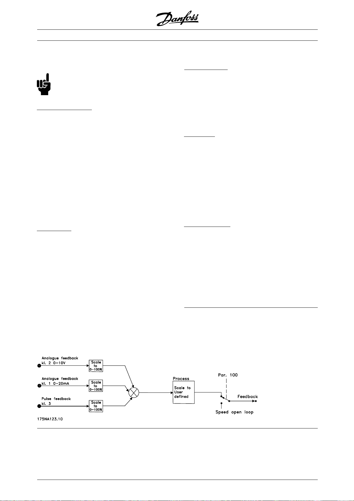
Note that the bus reference can only be preset
via serial communication.
NB!:
It is best to preset terminals that are not
being used to No function [0].
ifferentiator gain limit
D
If very rapid variations occur in an application in either
the reference signal or the feedback signal, the deviation
between the reference/setpoint and the process’s
actual mode will change quickly. The differentiator
can then become too dominant. This is because it
is reacting to the deviation between the reference
and the process’s actual mode, and the quicker the
variance changes the more powerful the differentiator’s
frequency contribution becomes. The differentiator’s
frequency contribution can therefore be limited in such a
way that both a reasonable differentiation time for slow
changes and an appropriate frequency contribution
for quick changes can be preset. This is done using
parameter 443 Process PID Differentiator gain limit.
owpass filter
L
If there is a lot of noise in the feedback signal, these
can be dampened using an integrated lowpass filter.
A suitable lowpass filter time constant is preset.
If the lowpass filter is preset to 0.1 s, the cut-off
frequency will be 10 RAD/sec, corresponding to (10 / 2
x π) = 1.6 Hz. This will mean that all currents/voltages
that vary by more than 1.6 oscillations per second
will be dampened. In other words, there will only
be regulation on the basis of a feedback signal
that varies by a frequency of less than 1.6 Hz. The
appropriate time constant is selected in parameter
444 Process PID lowpass filter time.
VLT®FCM Series
nverse regulation
I
Normal regulation means that the motor speed is
increased when the reference/setpoint is greater than
the feedback signal. If it is necessary to run inverse
regulation, in which the speed is reduced when
the reference/setpoint is greater than the feedback
signal, parameter 437 PID normal/inverse control
must be programmed at Inverted .
nti Windup
A
In the factory the process regulator is preset with
an active anti windup function. This function means
that when either a frequency limit, a current limit or
a voltage limit is reached, the integrator is initialised
at a frequency corresponding to the present output
frequency. This is a means of avoiding the integration
of a variance between the reference and the process’s
actual mode that cannot be deregulated by means of
a change of speed. This function can be deselected
in parameter 438 Process PID anti windup.
tarting conditions
S
In some applications the optimal setting of the
process regulator will mean that a relatively long
period of time will pass before the required process
condition is achieved. In these applications it can
be a good idea to define an output frequency to
which the frequency converter must run the motor
before the process regulator is activated. This is
done by programming a start frequency in parameter
439 Process PID start frequency.
■Handling of feedback
Feedback handling is depicted in this flowchart.
The flowchart shows which parameters can affect the
handling of feedback and how. A choice can be made
between voltage, current and pulse feedback signals.
✭ = factory setting. () = display text [] = value for use in communication via serial communication port
64
MG.03.H3.02 - VLT is a registered Danfoss trademark
Page 65
VLT®FCM Series
437 Process PID Normal/inverse control
(PROC NO/INV CTRL)
Value:
✭Normal (NORMAL)
Inverse (INVERSE)
Function:
It is possible to choose whether the process
regulator is to increase/reduce the output frequency
if there is a difference between the reference
signal and the feedback signal.
Used together with Process, closed loop
mode (parameter 100).
Description of choice:
If the FC motor is to reduce the output frequency in
case the feedback signal increases, select Normal [0].
If the FC motor is to increase the output frequency in
case the feedback signal increases, select Inverse [1].
438 Process PID anti windup
(PROC ANTI WINDUP)
Value:
Disable (DISABLE)
✭Enable (ENABLE)
Function:
It is possible to select whether the process regulator is
to continue regulating on an error even if it is notpossible
to increase/reduce the output frequency. Used together
with Process, closed loop mode (parameter 100).
Description of choice:
The factory setting is Enable [1], which means that
the integration link is adjusted in relation to the
actual output frequency if either the current limit or
the max./ min. frequency has been reached. The
process regulator will not engage again until either
the error is zero or its sign has changed.
[0]
[1]
[0]
[1]
439 Process PID start frequency
(PROC START VALUE)
Value:
f
MIN-fMAX
(PARAMETER 201 AND 202)
[X.X]
✭parameter 201
Function:
When the start signal comes, the FC motor will react
in the form of Speed, open loop mode following the
ramp. Only when the programmed start frequency
has been obtained, will it change over to Process,
closed loop mode. In addition, it is possible to set a
frequency that corresponds to the speed at which the
process normally runs, which will enable the required
process conditions to be reached sooner.
Used together with Process, closed loop
mode (parameter 100).
Description of choice:
Set the required start frequency.
NB!:
If the FC motor is running at the current limit
before the desired start frequency is obtained,
the process regulator will not be activated.
For the regulator to be activated anyway, the start
frequency must be lowered to the required output
frequency. This can be done during operation.
440 Process PID proportional gain
(PROC. PROP. GAIN)
Value:
0.00 (OFF) - 10.00
[0 - 1000]
✭0.01
Function:
The proportional gain indicates the number of
times the error between the set point and the
feedback signal is to be applied.
Programming
[1]
Select Disable [0] if the integrator is to continue
integrating on an error, even if it is not possible to
Used together with Process, closed loop
mode (parameter 100).
remove the fault by such regulation.
Description of choice:
NB!:
If Disable [0] is selected, it will mean that when
Quick regulation is obtained by a high gain, but if the
gain is too high, the process may become unstable.
the error changes its sign, the integrator will
first have to integrate down from the level
obtained as a result of the former error, before any
change to the output frequency occurs.
441 Process PID integral time
(PROC. INTEGR. T.)
Value:
0.01 - 9999 sec. (OFF)
✭9999 sec.
= factory setting. () = display text [] = value for use in communication via serial communication port
✭
MG.03.H3.02 - VLT is a registered Danfoss trademark
[1 - 999900]
[999900]
65
Page 66

VLT®FCM Series
Function:
The integrator provides an increasing gain at a constant
error between the set point and the feedback signal.
The greater the error, the quicker the gain will increase.
The integral time is the time needed by the integrator
to reach the same gain as the proportional gain.
Used together with Process, closed loop
mode (parameter 100).
Description of choice:
Quick regulation is obtained at a short integral
time. However, this time may become too short,
which can make the process unstable.
If the integral time is long, major deviations from
the required set point may occur, since the
process regulator will take a long time to regulate
in relation to a given error.
442 Process PID differentiation time
(PROC. DIFF. TIME)
Value:
0.00 (OFF) - 10.00 sec.
✭0.00 sec.
Function:
The differentiator does not react to a constant error.
It only provides a gain when the error changes.
The quicker the error changes, the stronger the
gain from the differentiator.
The gain is proportional to the speed at which
the error changes.
Used together with Process, closed loop
mode (parameter 100).
Description of choice:
Fast regulation is obtained with a long differentiation
time. However, this time may become too long,
which can make the process unstable.
443 Process PID diff. gain limit
(PROC. DIFF. GAIN)
Value:
5.0 - 50.0
✭5.0
Function:
It is possible to set a limit for the differentiator gain.
[0 - 1000]
[50 - 500]
[50]
[0]
The differentiator gain will increase if there are fast
changes, which is why it can be beneficial to limit
this gain, thereby obtaining a pure differentiator gain
at slow changes and a constant differentiator gain
where quick changes to the error occur.
Used together with Process, closed loop
mode (parameter 100).
Description of choice:
Select a limit to differentiator gain as required.
444 Process PID lowpass filter time
(PROC. FILTER TIME)
Value:
0.02 - 10.00 sec
✭0.02 sec
Function:
Oscillations on the feedback signal are dampened by
the lowpass filter in order to reduce their impact on
the process regulation. This can be an advantage
e.g. if there is a lot of noise on the signal.
Used together with Process, closed loop
mode (parameter 100).
Description of choice:
Select the desired time constant (τ). Ifatimeconstant
(τ) of 100 ms is programmed, the break frequency
for the lowpass filter will be 1/0.1 = 10 RAD/sec.,
correspondingto(10/2xπ)=1.6Hz.
The process regulator will thus o
signal that varies by a frequency lower than 1.6 Hz. If
the feedback signal varies by a higher frequency than
1.6 Hz, the Process regulator will not react.
445 Flying start
(FLYING START)
Value:
✭Disable (DISABLE)
OK - same direction (OK-SAME DIRECTION)
OK - both directions (OK-BOTH DIRECTIONS)
DC-brake before start
(DC-BRAKE BEF. START)
Function:
This function makes it possible to ‘catch‘ a motor,
which is spinning freely because of a mains dropout.
nly regulateafeedback
[2 - 1000]
[2]
[0]
[1]
[2]
[3]
= factory setting. () = display text [] = value for use in communication via serial communication port
✭
66
MG.03.H3.02 - VLT is a registered Danfoss trademark
Page 67

VLT®FCM Series
Description of choice:
Select Disable if this function is not required.
OK - same direction: Chosen if the motor can
only rotate in same direction on cut-in.
OK - both directions: Chosen if the motor can
rotate in both directions on cut-in.
DC-brake - before start: Selected if the motor is
to be stopped using DC brake before the motor is
ramped up to the desired speed. The DC brake
time must be set in parameter 126.
Limitations:
1. Too low inertia will cause acceleration of the load,
which may be dangerous or prevent succesful
Flying start. Use DC brake instead.
2. If load is driven eg. by "windmilling", the unit
might trip due to overvoltage.
3. Below 250 rpm the Flying start will not function.
446 Switching pattern
(SWITCH PATTERN)
Value:
60° AVM(60° AVM)
✭SFAVM (SFAVM)
Description of choice:
If Linear [0] is selected, the feedback signal and
the feedback value will be proportional.
If Square root [1] is selected, the frequency
converter translates the feedback signal to
be the square root value.
[0]
[1]
Function:
Description of choice:
Normally it is not necessary for the customer
to set this parameter.
461 Feedback conversion
(FEEDBACK CONV.)
Value:
✭Linear (LINEAR)
Square root(SQUARE ROOT)
Function:
In this parameter, a function is selected which
converts a connected feedback signal from the
process to a feedback value that equals the square
root of the connected signal.
This is used, e.g. where regulation of a flow (volume)
is required on the basis of pressure as feedback signal
(flow = constant x √pressure). This conversion makes
it possible to set the reference in such a way that
there is a linear connection between the reference
and the flow required. See drawing.
Programming
[0]
[1]
✭ = factory setting. () = display text [] = value for use in communication via serial communication port
MG.03.H3.02 - VLT is a registered Danfoss trademark
67
Page 68

VLT®FCM Series
500 Address
(BUS ADDRESS)
Value:
1 - 126
✭1
Function:
This parameter allows specification of the address of
each FC motor. This feature is used in connection
with PLC/PC connection.
Description of choice:
The individual FC motor can be given an address
between 1 and 126. The address 0 is used if a
master (PLC or PC) wishes to send a telegram that
is to be received by all FC motors connected to the
serial communication port at the same time. In this
case, the FC motor will not acknowledge receipt. If
the number of units connected (FC motors + master)
exceeds 31, a repeater is required.
501 Baudrate
(BAUDRATE)
Value:
300 Baud (300 BAUD)
600 Baud (600 BAUD)
1200 Baud (1200 BAUD)
2400 Baud (2400 BAUD)
4800 Baud (4800 BAUD)
9600 Baud (9600 BAUD)
[1 -126]
[1]
[0]
[1]
[2]
[3]
[4]
[5]
502 Coasting
(COASTING SELECT)
503 Quick-stop
(Q STOP SELECT)
504 DC-brake
(DC BRAKE SELECT)
505 Start
(START SELECT)
506 Reversing
(REVERSING SELECT)
507 Selection of Setup
(SETUP SELECT)
508 Selection of speed
(PRES.REF. SELECT)
Value:
Digital input (DIGITAL INPUT)
Bus (SERIAL PORT)
Logic and (LOGIC AND)
✭Logic or (LOGIC OR)
Function:
Parameters 502-508 allow a choice between
controlling the FC motor via the terminals (digital
input) and/or via the bus.
If Logic and or Bus is selected, the command
in question can only be activated if transmitted
via the serial communication port. In the case
of Logic and, the command must additionally be
activated via one of the digital inputs.
[0]
[1]
[2]
[3]
Function:
This parameter is for programming the speed
at which data is to be transmitted via the serial
connection. Baud rate is defined as the number
of bits transferred per second.
Description of choice:
The transmission speed of the FC motor is
to be set at a value that corresponds to the
transmission speed of the PLC/PC.
NB!:
Can not be changed via LCP 2. LCP 2 is only
capable to communicate at 9600 baud.
Description of choice:
Digital input [0] is selected if the control command in
question is only to be activated via a digital input.
Bus [1] is selected if the control command in
question is only to be activated via a bit in the
control word (serial communication).
Logic and [2] is selected if the control command
in question is only to be activated when a signal
is transmitted (active signal = 1) via both a
control word and a digital input.
Digital input
505-508 Bus Control command
00 0
01 0
10 0
11 1
Logic or [3] is selected if the control command in
question is to be activated when a signal is given (active
signal = 1) either via a control word or via a digital input.
= factory setting. () = display text [] = value for use in communication via serial communication port
✭
68
MG.03.H3.02 - VLT is a registered Danfoss trademark
Page 69
VLT®FCM Series
Digital input
505-508 Bus Control command
00 0
01 1
10 1
11 1
NB!:
Parameters 502-504 deal with stop functions
- see examples regarding 502 (coasting)
below. Active stop command "0".
Parameter 502 = Logic and
Digital input Bus Control command
001Coasting
0 1 0 Motor running
1 0 0 Motor running
1 1 0 Motor running
Parameter 502 = Logic or
Digital input Bus Control command
001Coasting
011Coasting
101Coasting
1 1 0 Motor running
This function is the same as in parameter 213.
Description of choice:
The jog frequency f
between f
(parameter 201) and f
MIN
can be selected in the range
JOG
(parameter 202).
MAX
512 Telegram profile
(TELEGRAM PROFILE)
Value:
Fieldbus Profile (FIELDBUS PROFILE)
✭FC Profile (FC PROFILE)
Function:
There is a choice of two different control word profiles.
Description of choice:
Select the desired control word profile.
See Serial communication for further information
about the control word profiles.
NB!:
This is only possible in Stop Mode (motor
stopped on a Stop command).
[0]
[1]
509 Bus jog 1
(BUS JOG 1 FREQ.)
Value:
0.0 - parameter 202
✭10.0 HZ
[0 -]
[100]
Function:
This is where to set a fixed speed (jog) that is activated
via the serial communication port.
This function is the same as in parameter 213.
Description of choice:
The jog frequency f
between f
(parameter 201) and f
MIN
can be selected in the range
JOG
(parameter 202).
MAX
510 Bus jog 2
(BUS JOG 2 FREQ.)
Value:
0.0 - parameter 202
✭10.0 HZ
[0 -]
[100]
Function:
This is where to set a fixed speed (jog) that is activated
via the serial communication port.
513 Bus time interval
(BUS TIMEOUT TIME)
Value:
1 - 99 sec.
[1-99]
✭1sec.
Function:
This parameter sets the maximum time expected
to pass between the receipt of two consecutive
telegrams. If this time is exceeded, the serial
communication is assumed to have stopped and the
desired reaction is set in parameter 514.
Description of choice:
Set the desired time.
514 Bus time interval function
(BUS TIMEOUT FUNC)
Value:
✭Off (OFF)
Freeze output (FREEZE OUTPUT)
Stop (STOP)
Jogging (JOGGING)
Max. speed (MAX SPEED)
Stop and trip (STOP AND TRIP)
Programming
[1]
[0]
[1]
[2]
[3]
[4]
[5]
= factory setting. () = display text [] = value for use in communication via serial communication port
✭
MG.03.H3.02 - VLT is a registered Danfoss trademark
69
Page 70

VLT®FCM Series
Function:
This parameter selects the desired reaction of the FC
motor when the set time for bus timeout (parameter
513) has been exceeded. If choices [1] to [5] are
activated, relay 01 and relay 04 will be de-activated.
Description of choice:
The output frequency of the FC motor can: be frozen
at the present value, be frozen at the reference,
go to stop, go to jogging frequency (parameter
213), go to max. output frequency (parameter
202) or stop and activate a trip.
515 Data read-out: Reference %
(REFERENCE)
Value:
XXX.X %
[XXXX]
Function:
This parameter can be read out via the serial
communication port.
Description of choice:
The value shown corresponds to the total
reference (sum of digital/analogue/preset/bus/freeze
ref./catchup and slow-down).
This value is updated every 320 ms.
517 Data read-out: Feedback
(FEEDBACK [UNIT])
Value:
X.XXX
Function:
This parameter can be read out via the serial
communication port.
Description of choice:
Indicates the status value of terminals 1/2 at the
unit/scale selected in parameters 414 and 415.
This value is updated every 320 ms.
518 Data read-out: Frequency
(FREQUENCY)
Value:
XXX.X Hz
Function:
This parameter can be read out via the serial
communication port.
Description of choice:
The value shown corresponds to the actual
motor frequency.
This value is updated every 320 ms.
[XXXX]
[XXXX]
516 Data read-out: Reference unit
(REFERENCE [UNIT])
Value:
X.XXX Hz or rpm.
Function:
This parameter can be read out via the serial
communication port.
Description of choice:
Indicates the status value of the unit given on the
basis of the choice of the reference sum.
This value is updated every 320 ms.
[XXXX]
519 Data read-out: Frequency x scale
(FREQUENCY X SCALE)
Value:
XXX.X Hz
[XXXX]
Function:
This parameter can be read out via the serial
communication port.
Description of choice:
The value corresponds to the present output frequency
multiplied by the factor preset in parameter 008
f
M
Display scaling of output frequency.
✭ = factory setting. () = display text [] = value for use in communication via serial communication port
70
MG.03.H3.02 - VLT is a registered Danfoss trademark
Page 71

VLT®FCM Series
520 Data read-out: Current
(MOTOR C URRENT)
Value:
XXX.XX A
Function:
This parameter can be read out via the serial
communication port.
Description of choice:
The value shown is a calculated value of the
given motor current.
This value is updated every 320 ms.
521 Data read-out: Torque
(TORQUE)
Value:
XXX.X %
Function:
This parameter can be read out via the serial
communication port.
Description of choice:
The value shown is the torque, with sign, supplied
to the motor shaft. The value is given as a
percentage of the rated torque.
[XXXXX]
[XXXX]
This value is updated every 320 ms.
523 Data read-out: Power, HP
(POWER (HP))
Value:
XX.XX HP (US)
Function:
This parameter can be read out via the serial
communication port.
Description of choice:
The value shown is calculated on the basis of
the actual motor voltage and motor current. The
value is indicated in the form of HP.
This value is updated every 320 ms.
524 Data read-out: Motor voltage
(MOTOR VOLTAGE)
Value:
XXX.X V
Function:
This parameter can be read out via the serial
communication port.
[XXXX]
[XXXX]
There is not exact linearity between 160% motor
current and torque in relation to the rated torque.
Due to tollerences and temperature differences some
motors supply more torque than that. Consequently,
the min. value and the max. value will depend
on the max./min. motor current.
This value is updated every 320 ms.
522 Data read-out: Power, kW
(POWER (KW))
Value:
XX.XX kW
Function:
This parameter can be read out via the serial
communication port.
Description of choice:
The value shown is calculated on the basis of the
actual motor voltage and motor current.
[XXXX]
Description of choice:
The value shown is a calculated value used
for controlling the motor.
This value is updated every 320 ms.
525 Data read-out: DC link voltage
(DC LINK VOLTAGE)
Value:
XXXX V
Function:
This parameter can be read out via the serial
communication port.
Description of choice:
The value shown is a measured value.
The value is filtered, which means that approx. 1.3
seconds may pass from an input value changes
until the data read-out changes values.
[XXXX]
Programming
= factory setting. () = display text [] = value for use in communication via serial communication port
✭
MG.03.H3.02 - VLT is a registered Danfoss trademark
71
Page 72

VLT®FCM Series
This value is updated every 320 ms.
527 Data read-out: FC therm.
(FC THERMAL)
Value:
0 - 100%
Function:
This parameter can be read out via the serial
communication port.
Description of choice:
Only whole numbers are displayed.
This value is updated every 160 ms.
528 Data read-out: Digital input
(DIGITAL INPUT)
Value:
Unit
Function:
This parameter can be read out via the serial
communication port.
[0 - 100]
534 Data read-out: Status word, binary
(STATUS WORD [HEX])
Value:
Unit
Function:
This parameter can be read out via the serial
communication port.
Description of choice:
Indicates the status word transmitted via the
serial communication port.
537 Data read-out: INV. temperature
(INVERTER TEMP.)
Value:
Unit: ºC
Function:
This parameter can be read out via the serial
communication port.
Description of choice:
States the given temperature of the frequency
converter. This value is updated every 10 sec.
Description of choice:
The value shown indicates the signal status from
the 4 digital terminals (2, 3, 4, and 5).
This value is updated every 20 ms.
533 Data read-out: External reference %
(EXT. REFERENCE)
Value:
-200.0 - +200.0 %
Function:
This parameter can be read out via the serial
communication port.
Description of choice:
The value stated gives, as a percentage, the sum of
external references (sum of analogue/bus/pulse).
This value is updated every 80 ms.
538 Data read-out: Alarm word
(ALARM WORD)
Value:
Unit
Function:
This parameter can be read out via the
serial communication port. See chapter on
"Warnings and alarms".
Description of choice:
States whether there is an alarm on the FC motor.
= factory setting. () = display text [] = value for use in communication via serial communication port
✭
72
MG.03.H3.02 - VLT is a registered Danfoss trademark
Page 73

VLT®FCM Series
Hex Fault messages
00000002 Trip lock
00000040 HPFB timeout
00000080 Standard bus timeout
00000100 Short circuit
00000200 24 V supply fault
00000400 Earth fault
00000800 Overcurrent
00004000 Motor thermistor
00008000 Inverter overload
00010000 Undervoltage
00020000 Overvoltage
00040000 Phase loss
00080000 Live zero error
00100000 Overtemperature
02000000 HPFB error
08000000 Inrush fault
10000000 Internal error
NB!:
This parameter is updated every 20 ms.
539 Data read-out: Control word
(CONTROL WORD)
Value:
Unit
Function:
This parameter can be read out via the serial
communication port.
Description of choice:
Indicates the control word sent via the serial
communication port in Hex code from the FC motor.
This parameter is updated every 20 ms.
Hex Warning messages
00000008 HPFB timeout
00000010 Standard bus timeout
00000040 Current limit
00000200 Inverter overload
00001000 Voltage warning low
00002000 Voltage warning high
00004000 Phase loss
00010000 Live zero error warning
00400000 Output freq. limit warning
00800000 HPFB error
40000000 24 V supply warning
80000000 Inverter temp. high
541 Data read-out: Extended status word
(STATUS WORD)
Value:
Unit
Function:
This parameter can be read out via the serial
communication port.
Description of choice:
States in Hex format whether there is a
warning on the FC motor.
Hex Status messages
01 Ramping
04 Start clockwise/counterclock-
wise
08 Slow down
10 Catch-up
8000 Frequency limit
Programming
542 Data read-out: Terminal 1, analogue input
540 Data read-out: Warning word
(WARN. WORD)
Value:
Unit
Function:
This parameter can be read out via the
serial communication port. See chapter on
"Warnings and alarms".
Description of choice:
States in Hex format whether there is a
warning on the FC motor.
= factory setting. () = display text [] = value for use in communication via serial communication port
✭
MG.03.H3.02 - VLT is a registered Danfoss trademark
(ANALOG INPUT 1)
Value:
Unit: mA
Function:
This parameter can be read out via the serial
communi
Descri
The value shown indicates the signal value on terminal 1.
The scaling (parameters 336 and 337) does not
influence the read-out. Min. and max. are determined
by the offset and gain adjustment of the AD-converter.
cation port.
ption of choice:
73
Page 74

This value is updated every 20 ms.
543 Data read-out: Terminal 2, analogue input
(ANALOG INPUT 2)
Value:
Unit: X.X V
Function:
This parameter can be read out via the serial
communication port.
Description of choice:
The value shown indicates the signal value on terminal 2.
The scaling (parameters 338 and 339) does not
influence the read-out. Min. and max. are determined
by the offset and gain adjustment of the AD-converter.
This value is updated every 20 ms.
VLT®FCM Series
✭ = factory setting. () = display text [] = value for use in communication via serial communication port
74
MG.03.H3.02 - VLT is a registered Danfoss trademark
Page 75

VLT®FCM Series
600 Operating data: Operating hours
(OPERATING HO URS)
Value:
Unit: hours
0.0 - 130,000.0
Function:
This parameter can be read out via the display or the
serial communication port. The value cannot be reset.
Description of choice:
Indicates the number of hours in which the FC
motor has been switched on.
The value is updated in the FC motor every hour
and saved when the unit is turned off.
601 Operating data: Hours run
(RUNNING HOURS)
Value:
Unit: hours
0.0 - 130,000.0
Function:
This parameter can be read out via the display
or the serial communication port. The value can
be reset via parameter 619.
Description of choice:
Indicates the number of hours in which the FC motor
has been in operation since reset in parameter 619.
The value is updated in the FC motor every hour
and saved when the unit is turned off.
604 Operating data: Number of
overtemperatures
(OVER TEMP’S)
Value:
Unit: number
0 - 9999
Function:
This parameter can be read out via the display
or the serial communication port.
Description of choice:
States the number of temperature faults there
has been on the FC motor.
605 Operating data: Number of overvoltages
(OVER VOLT’S)
Value:
Unit: number
0 - 9999
Function:
This parameter can be read out via the display
or the serial communication port.
Description of choice:
States the number of overvoltages there has
been on the FC motor.
Programming
615 Fault log: Error code
(F.LOG: ERROR COD)
Value:
[Index XX - XXX]
603 Operating data: Number of power-up’s
(POWER UP’S)
Value:
Unit: number
0 - 9999
Function:
This parameter can be read out via the display
or the serial communication port.
Description of choice:
States the number of power-ups of the supply
voltage to the FC motor.
✭
= factory setting. () = display text [] = value for use in communication via serial communication port
MG.03.H3.02 - VLT is a registered Danfoss trademark
Function:
Array type parameter. This parameter makes it possible
to see the reason why a trip occurs.
10 log values are stored.
The lowest log number (1) contains the latest/most
recently saved data value; the highest log number
(10) contains the oldest data value.
For additional information, see chapter on "
Warnings and alarms".
Description of choice:
Read out as a figure code between 1 and 37.
75
Page 76

VLT®FCM Series
Fault code Alarm
0Nofault
1
2 Technical Live zero error
3
4 Phase loss
7Overvoltage
8 Undervoltage
9Inverteroverload
11 Motor thermistor
13 Overcurrent
14 Earth fault
15 Supply fault
16 Short circuit
17 Standard BUS time out
18 HPFB time out
34 HPFB error
35 Inrush fault
36 Overtemperature
37 Internal error
The fault log is reset after initialization in parameter 620.
616 Fault log: Time
(F.LOG: TIME)
Value:
Unit: Hours
[Indication range XX - XXX]
Function:
Array type parameter. This parameter makes it possible
to see the total number of operating hours before the
trip occurred. 10 (1-10) log values are stored.
The lowest log number (1) contains the latest/most
recently saved data value, while the highest log
number (10) contains the oldest data value.
Description of choice:
Read out as an option.
Indication range: XX - XXX.
The fault log is reset after initialization (para. 620).
Description of choice:
Read out as one value.
Indication range: 0.0 - 999.9.
The fault log is reset after initialisation (para. 620).
619 Reset of hours-run counter
(RESET RUN. HOUR)
Value:
✭No reset (DO NOT RESET)
Reset (RESET COUNTER)
Function:
Reset to zero of hours-run counter (parameter 601).
Description of choice:
If Reset [1] has been selected the hours-run
counter of the FC motor is reset.
620 Operating mode
(OPERATION MODE)
Value:
Normal function (NORMAL OPERATION)
Control card test (CONTROL CARD TEST)
Initialisation (INITIALIZE)
Function:
In addition to its normal function, this parameter
can be used for two different tests.
Also, all parameters (except parameters
603-605) can be initialized.
Description of choice:
Normal function [0] is selected for normal operation
with the motor in the selected application.
Control card test [2] is selected if control of the
analogue and digital inputs, as well as the analogue,
digital outputs and the +10 V control voltage is desired.
A test connector with internal connections is required for
this test. Setup: Analogue/digital output to digital inputs
3, 4 and 5 and 10 V supply to analogue/digital input 2.
[0]
[1]
[0]
[2]
[3]
617 Fault log: Value
(F.LOG: VALUE)
Value:
[Index XX - XXX]
Function:
Array type parameter. This parameter makes it possible
to see at what current or voltage a given trip occurred.
✭ = factory setting. () = display text [] = value for use in communication via serial communication port
76
Initialization [3] is selected if the factory setting of the
unit is desired without resetting parameters 500, 501
+ 600 - 605. Initialisationis active after power up.
MG.03.H3.02 - VLT is a registered Danfoss trademark
Page 77

VLT®FCM Series
621 Nameplate: FC type
(FC TYPE)
Value:
Depends on unit
Function:
The key data of the unit can be read out via the
display or the serial communication.
Description of choice:
Type indicates the unit size and basic
function concerned.
624 Nameplate: Software version no.
(SOFTWARE VERSION)
Value:
Depends on unit
Function:
The key data of the unit can be read out via the
display or the serial communication.
Description of choice:
Software version gives the version number.
628 Nameplate: Application option type
(APP. OPTION)
Value:
Function:
The key data of the unit can be read out via the
display or the serial communication port.
630 Nameplate: Communication option
type ordering no.
(COM. ORDER NO)
Value:
Function:
The key data of the unit can be read out via the
display or the serial communication port.
632 BMC software identification
(BMC SW VERSION)
Value:
625 Nameplate: LCP identification no.
(LCP VERSION)
Value:
Depends on unit
Function:
The key data of the unit can be read out via
the display or the serial communication port.
Forexample: ID1,422kB.
626 Nameplate: Database identification no.
(DATABASE VER.)
Value:
Depends on unit
Function:
The key data of the unit can be read out via the
display or the serial communication port.
Function:
The key data of the unit can be read out via the
display or the serial communication port.
Programming
633 Motor database identification
(MOTOR DATA VERS.)
Value:
Function:
The key data of the unit can be read out via the
display or the serial communication port.
634 Unit identification for communication
(UNIT ID)
Value:
Function:
The key data of the unit can be read out via the
display or the serial communication port.
✭ = factory setting. () = display text [] = value for use in communication via serial communication port
MG.03.H3.02 - VLT is a registered Danfoss trademark
77
Page 78

VLT®FCM Series
■PC Software tools
PC Software - MCT 10
All drives are equipped with a serial communication
port. We provide a PC tool for communication
between PC and frequency converter, VLT Motion
Control Tool MCT 10 Set-up Software.
MCT 10 Set-up Software
MCT 10has been designed as an easy to use interactive
tool for setting parameters in our frequency converters.
The MCT 10 Set-up Software will be useful for:
• Planning a communication network off-line. MCT 10
contains a complete frequency converter database
• Commissioning frequency converters on line
• Saving settings for all frequency converters
• Replacing a drive in a network
• Expanding an existing network
• Future developed drives will be supported
The MCT 10 Set-up Software Modules
The following modules are included in the
software package:
MCT 10 Set-up Software
Setting parameters
Copy to and from frequency
converters
Documentation and print out of
parameter settings incl. diagrams
SyncPos
Creating SyncPos programme
Ordering number:
Please order your CD containing MCT 10 Set-up
Software using code number 130B1000.
PC Software - VLT Software Dialog:
For single or few unit installations a basic software
package, VLT Software Dialog, is available. Please
order using code number 175Z0967.
■ Serial bus
■ Telegram communication
ontrol and reply telegrams
C
The telegram communication in a master/slave
system is controlled by the master. A maximum
of 31 slaves (FC motors) can be connected to one
master, unless a repeater is used - see also the
description of the address format.
The master continuously sends control telegrams
addressed to the slaves and awaits reply
telegrams from these. The response time of
the slaves is maximum 50 ms.
Only a slave that has received a faultless telegram
addressed to that slave will respond by sending
back the telegram unchanged.
roadcast
B
A master can send the same telegram at the same
time to all slaves connected to the bus. In such
78
broadcast communication, the control telegram
broadcast bit of the address bit has a value of 1 (see
VLT address). Address bits 0-4 are not used.
ontents of a byte
C
Each transmitted sign begins with a start bit.
Subsequently, 8 databits are transmitted. Each sign
is given via a parity bit set at "1" when there is an
even parity (i.e. an even number of binary 1’sinthe8
databits and parity bits together). The sign ends with a
stop bit and thus consists of a total of 11 bits.
■ Telegram build-up
Each telegram begins with a startbyte (STX) = 02 Hex,
followed by a byte that gives the telegram length (LGE)
MG.03.H3.02 - VLT is a registered Danfoss trademark
Page 79

VLT®FCM Series
and a byte that gives the address (ADR). Then follows a
number of databytes (variable, depending on telegram
type). The telegram ends with a data control byte (BCC).
Telegram length (LGE)
The telegram length is the number of databytes plus
address byte ADR plus data control byte BCC.
Telegrams with 4 databytes have a length of:
LGE=4+1+1=6bytes
Telegrams with 12 databytes have a length of:
LGE=12+1+1=14bytes
LT address (ADR)
V
Two different address formats are used:
1. Siemens USS protocol address format:
BCC
BCC
EXOR and gives a new BCC
OLD
=00000010
OLD
NEW
, e.g.:
EXOR
second byte" = 1 1 0 1 0 1 1 0 (D6H)
"
BCC
=11010100
NEW
The result after the last received sign is BCC.
■ Databytes
The block of databytes is divided into two
smaller blocks:
1. Parameter bytes used for transferred parameters
between master and slave
2. Process bytes, covering
- Control word and reference value (from
master to slave)
- Status word and present output frequency
(from slave to master)
This structure applies to both the control
telegram (master → slave) and the reply
telegram (slave → master).
Bit 7 = 0
Bit6isnotused
Bit 5 = 1: Broadcast, address bits (0-4) are not used
Bit 5 = 0: No Broadcast
Bits0-4=VLTaddress1-31
2. Danfoss format:
Bit 7 = 1
Bits 0-6 = VLT address 1-127 (0 = Broadcast)
ata control byte (BCC)
D
The data control byte can best be explained by
means of an example: Before the first sign of the
telegram is received, BCC = 0.
After the first sign has been received:
BCC
NEW
=BCC
EXOR "first byte"
OLD
(EXOR = exclusive-or gate)
BCC
=00000000
OLD
EXOR
first byte" = 0 0 0 0 0 0 1 0 (02H)
"
BCC
=00000010
NEW
Each additional, subsequent byte is gated by
There are two types of telegrams:
- with 12 bytes built up as shown above, with
parameter and process block
- with four bytes, which is the process block
from the 12 byte telegram
. Parameter bytes
1
Commands and replies (AK)
Bits no. 12-15 are used for transmitting commands
from master to slave and the slave’s processed
reply back to the master.
Commands master → slave:
Programming
MG.03.H3.02 - VLT is a registered Danfoss trademark
79
Page 80

VLT®FCM Series
Bit no.
15 14 13 12 Command
0 0 0 0 No command
0 0 0 1 Read parameter value
0 0 1 0 Write parameter value in
RAM (word)
0 0 1 1 Write parameter value in
RAM (double word)
1 1 0 1 Write parameter value in
RAM and EEPROM (double
word)
1 1 1 0 Write parameter value in
RAM and EEPROM (word)
11 11Readtext
Reply slave → master:
Bit no.
15 14 13 12 Reply
00 00Noreply
0 0 0 1 Parameter value transferred
(word)
0 0 1 0 Parameter value transferred
(double word)
0 1 1 1 Command cannot be
executed
1 1 1 1 Text transferred
Bits no. 0-10 are used for transmitting parameter
numbers. The function of a given parameter can be
seen from the parameter description in chapter 8.
Index
Index is used together with the parameter number
for read/write access to parameters of the array
type (par. 615, 616 and 617).
arameter value (PWE)
P
The parameter value depends on the command
given. If the master wants a parameter (read), it does
not care about the PWE block value. If a parameter
is changed by the master (write), the new value is
transferred in the PWE block. If the slave replies to
a parameter request (read command), the present
parameter value is transferred to the PWE block.
If the command cannot be executed, the slave
will send this reply (0111) and give the following
error message in the parameter value:
Error code
(reply 0111) Error message
0 The parameter number used does not
exist
1 There is no write access to the
parameter called
2 The data value exceeds the parameter
limits
3 The used sub-index does not exist
4 The parameter is not of the array type
5 The data type does not match the
parameter called
17 Data change in the parameter called
is not possible in the present mode of
the FC motor. E.g. some parameters
can only be changed when the motor
has stopped
130 There is no bus access to the
parameter called
131 Data change is not possible because
factory Setup has been selected
Parameter number (PNU)
The transferred value corresponds to the figures
given in the parameter descriptions in chapter 8. E.g.
parameter 101, where [1] corresponds to Constant
torque, [2] corresponds to Variable torque: low,etc.
However, parameters with data type 9 (text string) are
excepted, as this text is transferred as an ASCII text
string. When a text string is transferred (read), the
telegram length is variable, since the texts have different
lengths. The telegram length is stated in the 2nd byte
of the telegram, called LGE, see page 73. Parameters
621-634 (nameplate data) have data type 9 (text string).
ata types supported by the VLT frequency converter
D
Data type Description
3Integer16
4Integer32
5 Unsigned 8
6 Unsigned 16
7 Unsigned 32
9Textstring
Unsigned means there is no sign included
in the telegram.
The different attributes for each parameter can be
seen in the section on factory settings. Since a
parameter value can only be transferred as an integer,
aconversionfactormustbeusedtotransferdecimals.
80
MG.03.H3.02 - VLT is a registered Danfoss trademark
Page 81

VLT®FCM Series
Example:
Parameter 201: minimum frequency, conversion factor
0,1. If parameter 201 is to be set to 10 Hz, a value of
100 must be transferred, since a conversion factor of
0,1 means that the transferred value will be multiplied
by 0.1. A value of 100 will thus be understood as 10.
ddressing by unit ID
A
2. Process-bytes
The process byte block is divided into two blocks each
of 16 bits, which always come in the sequence stated.
■Controlwordaccording to FieldbusProfileStandard
(parameter 512 = Fieldbus Profile) The control word
is used for transmitting commands from a master
(e.g. a PC) to a slave (FC motor).
The unit ID is printed on the label on the plastic
cover under the lid of the electronics box. The three
groups of unit ID each with three digits must be
converted to Hex. The desired address is added as
the last byte. The frame is sent to the bus address
parameter(s) 500 (and 918) via a broadcast.
PKE: Write to parameter No. 500 or 918
IND: Not Used
PCD1 PCD2
Control
telegram
Control word Reference
value
(master→slave)
Reply telegram
(slave→master)
NB!:
The use of Bit 00, Bit 01 and Bit 02 for
switching off the power supply (by use of
relay) will require a separate power on. This
because there is no 24V external connection to supply
the FCM 300 control, which is required to activate
the FCM 300 again via input signal.
Status word Given output
frequency
Bit Bit = 0 Bit =1
00 OFF 1 ON 1
01 OFF 2 ON 2
02 OFF 3 ON 3
03 Motor coasting Enable
04 Quick-stop Ramp
05 Freeze output frequency Ramp enable
06 Ramp stop Start
07 No function Reset
08 Jog1OFF ON
09 Jog2OFF ON
10 Data not valid Valid
11 No function Slow down /
Relay 123 / Digital
output terminal 9
12 No function Catch-up / Relay
123
13 Setup 1 Setup 2
14
15 No function Reversing
it 00, OFF1/ON1:
B
An ordinary ramp stop which uses the ramp time
in parameters 207/208. Bit 00 = "0" leads to
a stop. Bit 00 = "1" means that the frequency
converter will be able to start if the other conditions
for starting have been fulfilled.
it 01, OFF2/ON2:
B
Coasting stop. Bit 01 = "0" leads to a coasting stop.
Bit 01 = "1" means that the frequency converter
is able to start, provided the other conditions
for starting have been fulfilled.
it 02, OFF3/ON3:
B
Quick-stop, which uses the ramp time in parameter 212.
Bit 02 = "0" leads to a quick-stop. Bit 02 = "1" means
that the frequency converter is able to start, provided
the other conditions for starting have been fulfilled.
it 03, Coasting/enable:
B
Coasting. Bit 03 = "0" leads to a stop. Bit 03 =
"1" means that the frequency converter is able to
start, provided the other conditions for starting are
fulfilled. Note: In parameter 502 the choice is made
Programming
MG.03.H3.02 - VLT is a registered Danfoss trademark
81
Page 82
VLT®FCM Series
as to how bit 03 is to be combined (gated) with the
corresponding function in the digital inputs.
B
it 04, Quick-stop/ramp:
Quick-stop which uses the ramp time in parameter
212. Bit 04 = "0" leads to a quick-stop. Bit 04 =
"1" means that the frequency converter is able to
start, provided the other conditions for starting are
fulfilled. Note: In parameter 503 the choice is made
as to how bit 04 is to be combined (gated) with the
corresponding function on the digital inputs.
it 05, Freeze output frequency/ramp enable:
B
Bit 05 = "0" means that the given output frequency is
maintained even if the reference is changed. Bit 05 =
"1" means that the frequency converter is again able
to regulate, and the given reference is followed.
it 06, Ramp stop/start:
B
An ordinary ramp stop that uses the ramp time in
parameters 207/208. Bit 06 = "0" leads to a stop. Bit
06 = "1" means that the frequency converter is able to
start, provided the other conditions for starting have
been fulfilled. Note: In parameter 505 the choice is
made as to how bit 06 is to be combined (gated) with
the corresponding function on the digital inputs.
it 07, No function/reset
B
Resetoftrip.Bit07="0"meansthatthereisnoreset.
Bit 07 = "1" means that a trip is reset. After reset it
will take approx. 1.5 second until the unit is ready.
The status word will indicate the ready state.
it 08, Jog 1 OFF/ON:
B
Activation of pre-programmed speed in parameter
509 (Bus JOG 1). JOG 1 is only possible when
Bit 04 = "0" and bit 00-03 = "1".
it 09, Jog 2 OFF/ON:
B
Activation of pre-programmed speed in parameter
510 (Bus JOG 2). JOG 2 is only possible when Bit
04 = "0" and Bits 00-03 = "1". If both JOG 1 and
JOG 2 are activated (Bits 08 and 09 = "1"), JOG 1
has the higher priority, which means that the speed
programmed in parameter 509 will be used.
it 10, Data not valid/valid:
B
Used for telling the FC motor whether the control word
is to be used or ignored. Bit 10 = "0" means that the
control word is ignored. Bit 10 = "1" means that the
control word is used. This function is relevant because
the control word is always contained in the telegram,
regardless of the type of telegram used, i.e. it is possible
to disconnect the control word if it is not to be used in
connection with updating or reading of parameters.
it 11, No function / slow down, relay 123,
B
digital output terminal 9:
Used for reducing the speed reference by the value in
parameter 219. Bit 11 = "0" means that there is no
change of the reference. Bit 11 = "1" means that the
reference is reduced. Bit 11 = "1" will also activate
relay 123 (provided parameter 323 = "Control word
bit 11") and set digital out terminal 9 high (provided
parameter 340 = "Control word bit 11").
it 12, No function / catchup, relay 123:
B
Used for increasing the speed reference by the value
of parameter 219. Bit 12 = "0" means that there is
no change of the reference; Bit 12 = "1" means that
the reference is increased. If both slow down and
catchup are activated (Bits 11 and 12 = "1"), slow
down has the higher priority, i.e. the speed reference
is reduced. Bit 12 = "1" will also activate relay 123
(provided parameter 323 = "Control word bit 12").
its 13, Choice of Setup:
B
Bit 13 is used for choosing between the two menu
Setups in accordance with the following table:
Setup Bit 13
10
21
This function is only possible if Multi-Setups have
been selected in parameter 004.
NB!:
Parameter 507 is used for choosing how
Bit 13 is to be combined (gated) with the
corresponding function on the digital inputs.
it 15, No function/reversing:
B
Reversing of the direction of rotation of the
motor. Bit 15 = "0" leads to no reversing, Bit
15 = "1" leads to reversing.
NB!:
Unless otherwise mentioned, the control
word bit is combined (gated) with the
corresponding function on the digital
inputs as a logic "or" function.
tatus word (according to Fieldbus
S
Profile standard)
The status word is used for informing the master (e.g.
a PC) of the condition of a slave (FC motor).
82
MG.03.H3.02 - VLT is a registered Danfoss trademark
Page 83
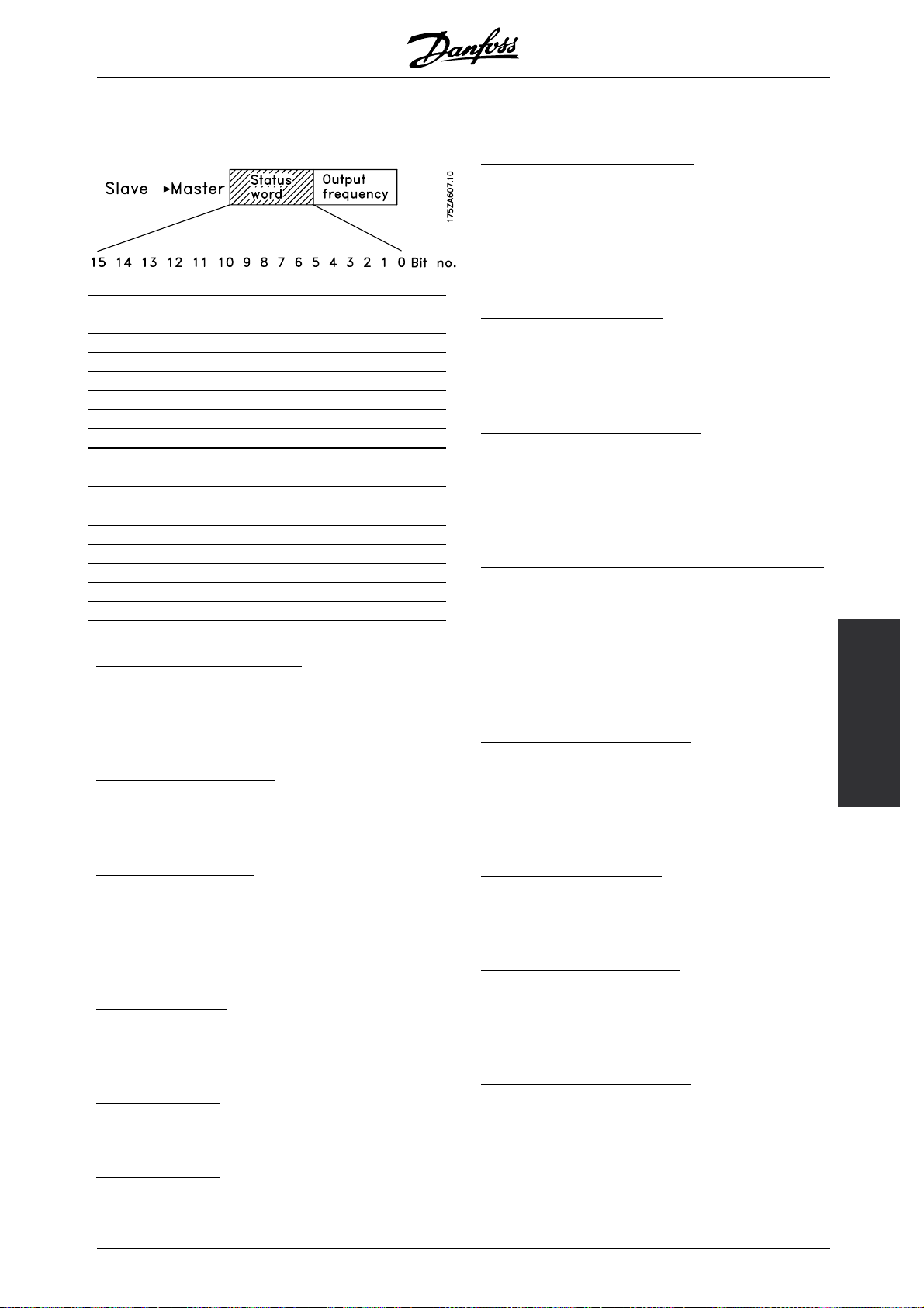
Bit Bit = 0 Bit =1
00 Control not ready Ready
01 FC not ready Ready
02 Coasting Enable
03 No fault Trip
04 ON 2 OFF 2
05 ON 3 OFF 3
06 Start enable Start disable
07 No warning Warning
08 Speed ≠ ref. Speed = ref.
09 Local control Serial communication
10 Outside frequency
Frequency limit OK
range
11 Not running Running
12
13 Voltage OK Above limit
14 Current OK Above limit
15 Thermal warning
Bit 00, Control not ready/ready:
Bit 00 = "0" means that bit 00, 01 or 02 of the
control word is "0" (OFF1, OFF2 or OFF3), or that the
frequency converter has tripped. Bit 00 = "1" means
that the frequency converter control is ready.
it 01, FC not ready/ready:
B
Same meaning as bit 00; however, there is also a supply
to the power section, and the frequency converter is
ready to run when it receives the necessary start signals.
VLT®FCM Series
it 06, Start enable/start disable:
B
Bit 06 is always "0" if FC Drive has been selected
in parameter 512. If Profidrive has been selected in
parameter 512, bit 06 will be "1" after reset of a trip,
after activation of OFF2 or OFF3 and after connection
of mains voltage. Start disable is reset, setting control
wordbit00to"0"andbits01,02and10to"1".
it 07, No warning/warning:
B
Bit 07 = "0" means that there is no unusual situation. Bit
07 = "1" means that an abnormal condition has arisen
for the FC motor. All warnings described in section List
of warnings and alarms will set bit 07 to "1".
it 08, Speed ≠ ref/speed. = ref.:
B
Bit 08 = "0" means that the actual motor speed is
different from the speed reference set. This can be
thecasei.a. whilethespeedisrampedup/down
during start/stop. Bit 08 = "1" means that the present
motor speed equals the speed reference set.
it 09, Local operation / serial communication control:
B
Bit 09 = "0" means that [STOP/RESET] is activated
on the control unit, or that Local control in parameter
002 Local/remote operation is selected. It is not
possible to control the frequency converter via
serial communication. Bit 09 = "1" means that
it is possible to control the frequency converter
via serial communication.
it 10, Outside frequency range:
B
Bit 10 = "0", if the output frequency has reached
the value in parameter 201Output frequency low
limit or parameter 202 Output frequency high l imit.
Bit 10 = "1" means that the output frequency
is within the defined limits.
Programming
it 02, Coasting/enable:
B
Bit 02 = "0" means that the control word bit 00, 01,
02 or 03 is "0" (OFF1, OFF2, OFF3 or Coasting), or
the FCM 300 Series unit has tripped. Bit 02 = "1"
means that the control word bits 00, 01, 02 or 03 are
"1" and that the FC motor has not tripped.
it 03, No fault/trip:
B
Bit 03 = "0" means that FCM 300 Series is not in a fault
condition. Bit 03 = "1" means that FCM 300 Series has
tripped and needs a reset signal in order to run.
it 04, ON2/OFF2:
B
Bit 04 = "0" means that control word bit 01 = "1". Bit
04 = "1" means that control word bit 01 = "0".
it 05, ON3/OFF3:
B
Bit 05 = "0" means that control word bit 02 = "1". Bit
05 = "1" means that control word bit 02 = "0".
MG.03.H3.02 - VLT is a registered Danfoss trademark
it 11, Not running/running:
B
Bit 11 = "0" means that the motor is not running. Bit
11 = "1" means that the FC motor has a start signal or
that the output frequency is greater than 0 Hz.
it 13, Voltage OK/above limit:
B
Bit 13 = "0" means that the voltage limits of the
FC motor have not been exceeded. Bit 13 =
"1" means that the DC voltage of the FC motor
intermediate circuit is too low or too high.
it 14, Current OK / above limit:
B
Bit 14 = "0" means that the motor current is
lower than the current limit selected in parameter
221. Bit 14 = "1" means that the current limit in
parameter 221 has been exceeded.
it 15, Thermal warning:
B
83
Page 84

VLT®FCM Series
Bit 15 = "0" means that the timers for motor thermal
protection and VLT thermal protection, respectively,
Control word under FC Profile (parameter
512 = FC Drive)
The control word is used for sending commands from
a master (e.g. a PC) to a slave (FC motor).
Bit Bit = 0 Bit =1
00 Preset reference choice
01 No function
02 DC brake Ramp
03 Coasting Enable
04 Quick-stop Ramp
05 Hold Ramp enable
06 Ramp stop Start
07 No function Reset
08 No function Jog
09 No function
10 Data not valid Valid
11 No function Relay 123 / digital
input terminal 9
12 No function Relay 123
13 Setup 1 Setup 2
15 No function Reversing
Bit 00:
Bit 00 is used for choosing between the two
pre-program
in accordance with the following table:
med references (parameters 215-216)
have not exceeded 100%. Bit 15 = "1" means that
one of the timers has exceeded 100%.
provided the other conditions for starting have been
fulfilled. Note: In parameter 502 the choice is made
as to how bit 03 is to be combined (gated) with the
corresponding function in the digital inputs.
it 04, Quick-stop / ramp:
B
Quick-stop which uses the ramp time in parameter
212. Bit 04 = "0" leads to a quick-stop. Bit 04 = "1"
means that the frequency converter is able to start,
provided the other conditions for starting have been
fulfilled. Note: In parameter 503 the choice is made
as to how bit 04 is to be combined (gated) with the
corresponding function on the digital inputs.
it 05, Hold / ramp enable:
B
Bit 05 = "0" means that the given output frequency is
maintained even if the reference is changed. Bit 05 =
"1" means that the frequency converter is again able
to regulate, and the given reference is followed.
it 06, Ramp stop / start:
B
An ordinary ramp stop that uses the ramp time in
parameters 207/208. Bit 06 = "0" leads to a stop. Bit
06 = "1" means that the frequency converter is able to
start, provided the other conditions for starting have
been fulfilled. Note: In parameter 505 the choice is
made as to how bit 06 is to be combined (gated) with
the corresponding function on the digital inputs.
it 07, No function / reset:
B
Reset of trip. Bit 07 = "0" means that there is no reset.
Bit 07 = "1" means that a trip is reset. After reset it
will take approx. 1.5 second until the unit is ready.
The status word will indicate the ready state.
Preset ref. Parameter Bit 00
1 215 0
2 216 1
NB!:
Parameter 508 is where to choose the way
bits 1/12 are to be combined (gated) with the
corresponding function on the digital inputs.
it 02, DC brake:
B
Bit 02 = "0" leads to DC braking and stop. Braking
current and duration are set in parameters 132
and 133. Bit 02 = "1" leads to ramp.
it 03, Coasting/enable:
B
Coasting. Bit 03 = "0" leads to a stop. Bit 03 = "1"
means that the frequency converter is able to start,
84
it 08, Activation of Jog speed in parameter 213:
B
Bit 08 = "0": Jog speed not activated. Bit 08 = "1"
means that the motor is running at Jog speed.
B
it 10, Data not valid / valid:
Used for telling the FC motor whether the control word
is to be used or ignored. Bit 10 = "0" means that the
control word is ignored. Bit 10 = "1" means that the
control word is used. This function is relevant because
the control word is always contained in the telegram,
regardless of the type of telegram used, i.e. it is possible
to disconnect the control word if it is not to be used in
connection with updating or reading of parameters.
it 11, No function / relay 123, digital output terminal 9:
B
MG.03.H3.02 - VLT is a registered Danfoss trademark
Page 85

VLT®FCM Series
Bit 11 = "1" will activate relay 123 (provided parameter
323 = "Control word bit 11") and set digital out terminal
9 high (provided parameter 340 = "Control word bit 11").
it 12, No function / relay 123:
B
Bit 12 = "1" will activate relay 123 (provided parameter
323 = "Control word bit 12").
B
it 13, Choice of setup:
Bit 13 is used for choosing between the two menu
setups in accordance with the following table:
Setup Bit 13
10
21
This function is only possible if Multi-Setups have
been selected in parameter 004.
NB!:
Parameter 507 is used for c
Bit13istobecombined(gated)withthe
corresponding function on the digital inputs.
it 15, No function / reversing::
B
Reversing of the dire
motor. Bit 15 = "0" leads to no reversing. Bit
15 = "1" leads to reversing..
ction of rotation of the
hoosing how
Status word under FC Profile
The status word is used for informing the master (e.g.
a PC) about the condition of the slave (FC motor).
Bit Bit = 0 Bit =1
00 Control not ready Ready
01 FC not ready Ready
02 Coasting Enable
03 No fault Trip
04 Reserved
05 Reserved
06 Reserved
07 No warning Warning
08 Speed ≠ ref. Speed = ref.
09 Local control Bus control
10 Out of range Frequency OK
11 Not running Running
12
13 Voltage OK Above limit
14 Current OK Above limit
15 Timer OK Thermal warning
NB!:
Unless otherwis
word bit is combined (gated) with the
corresponding function on the digital
inputs as a
logic "or" function.
e mentioned, the control
Bit 01, FC not ready/ready:
Bit 01 = "0" means that the frequency
converter has tripped.
Bit 01 = "1" means that the frequency converter is ready.
it 02, Coasting/enable:
B
Bit 02 = "0" means that the control word bit 03 is "
(Coasting) or that the FC motor has tripped.
Bit02="1"meansthatcontrolwordbit03is"1"
and that the FC motor has not tripped.
it 03, No fault / trip:
B
Bit 03 = "0" means that FCM 300 Series is not in a fault
condition. Bit 03 = "1" means that FCM 300 Series has
tripped and needs a reset signal in order
it 07, No warning / warning:
B
Bit 07 = "0" means that there is no unusual situation.
Bit 07 = "1" means that an abnormal condition has
arisen for the FC motor. All warnin
part List of warnings and alarms will set bit 07 to "1".
it 08, Speed ≠ ref/speed. = ref.:
B
Bit 08 = "0" means that the actual motor speed is
different from the speed refe
thecasei.e. whilethespeedisrampedup/down
during start/stop. Bit 08 = "1" means that the present
motor speed equals the sp
rence set. This can be
eed reference set.
to run.
gs described in the
0"
Programming
MG.03.H3.02 - VLT is a registered Danfoss trademark
85
Page 86

VLT®FCM Series
Bit 09, Local operation / bus control:
Bit 09 = "0" means that [STOP/RESET] is activated
on the control unit, or that Local control in parameter
002 Local/remote operation is selected. It is not
possible to control the frequency converter via
serial communication. Bit 09 = "1" means that
it is possible to control the frequency converter
via serial communication.
it 10, Out of range/frequency:
B
Bit 10 = "0", if the output frequency has reached
the value in parameter 201 Output frequency
low limit or parameter 202 Output frequency
high limit. Bit 10 = "1" means that the output
frequency is within the defined limits.
it 11, Not running / running:
B
Bit 11 = "0" means that the motor is not running. Bit
11 = "1" means that the FC motor has a start signal or
that the output frequency is greater than 0 Hz.
it 13, Voltage OK / above limit:
B
Bit 13 = "0" means that the voltage limits of the
FC motor have not been exceeded. Bit 13 =
"1" means that the DC voltage of the FC motor
intermediate circuit is too low or too high.
Parameter 203 = "1"
MAX
-+ref
MAX
-ref
-16384 (...Hex)-+16384 (4000 Hex) ~
-100- +100% ~ -ref
MAX
-+ref
MAX
Actual output frequency
The value of the actual output frequency of the
frequency converter is transmitted in the form
of a 16- bit word. The value is transmitted as
a whole number (0-32767). 16384 (4000 Hex)
corresponds to 100%. (Negative figures are formed
by means of 2’s complement).
it 14, Current OK / above limit:
B
Bit 14 = "0" means that the motor current is
lower than the torque limit selected in parameter
221. Bit 14 = "1" means that the torque limit in
parameter 221 has been exceeded.
it 15, Thermal warning:
B
Bit 15 = "0" means that the timers for motor thermal
protection and VLT thermal protection, respectively,
have not exceeded 100%. Bit 15 = "1" means that
one of the timers has exceeded 100%.
us reference value:
B
The frequency reference value is transmitted to the
frequency converter in the form of a 16-bit word. The
value is transmitted as a whole number (0-32767).
16384 (4000 Hex) corresponds to 100%. (Negative
figures are formed by means of 2’s complement.)
The bus reference has the following format:
Parameter 203 = "0"
-ref
"ref
MIN
0-16384 (4000 Hex) ~ 0-100% ~ ref
MAX
"
-ref
MIN
86
MAX
MG.03.H3.02 - VLT is a registered Danfoss trademark
Page 87

VLT®FCM Series
■ Galvanic isolation (PELV)
PELV offers protection by way of extra low voltage.
Protection against electric shock is considered to
be ensured when all connected devices are of the
PELV type and the installation is made as described
in local/national regulations on PELV supplies.
In FCM 300 Series all control terminals are supplied
from or in connection with extra low voltage (PELV).
Galvanic (ensured) isolation is obtained by fulfilling
requirements concerning higher isolation and
by providing the relevant creapage/clearance
distances. These requirements are described
in the EN 50178 standard.
The components that make up the electrical
isolation, as described below, also comply with the
requirements concerning higher isolation and the
relevant test as described in EN 50178.
The galvanic isolation can be shown in three
locations (see drawing below), namely:
1. Power supply (SMPS) incl. signal isolation of U
indicating the intermediate current voltage.
2. Gate drive that runs the IGBTs (optocouplers).
3. Current transducers (opto-couplers).
■ Earth leakage current
Earth leakage current is primarily caused by the
capacitance between motor phases and the
motor frame. The RFI filter contributes additional
leakage current, as the filter circuit is connected
to earth through capacitors.
The size of the leakage current to the ground depends
on the following factors, in order of priority:
DC
1. Switching frequency
2. Motor grounded on site or not
The leakage current is of importance to safety during
handling/operation of the frequency converter if (by
mistake) the frequency converter has not been earthed.
NB!:
FCM 305-375 all have leakage currents > 3.5
mA,approx4to20mA.Varieswithswitching
frequencies within the given interval.
This means reinforced earthing mus be established
(see Quick Guide MG.03.A1.02), if EN50178
is to be complied with.
Never use ELCB (Earth Leakage Circuit Breaker) relays
also called RCD(Residual Current Device) that are
not suitable for DC fault currents (type A).
If a RCD is used it must be:
- Suitable for protecting equipment with a DC current
content in the fault current (3-phase rectifier)
- Suitable for power-up with short charging
,
current to earth
- Suitable for a high leakage current.
ThismeansitispossibletooperatetheFCM
300 on RCD type B:
Residual Current Devices (RCD) type B has a tolerance
on trip level. It is therefore recommended to use a
RCD where the max leakage current for the FCM (see
above, 20 mA) is less than 1/3 of the trip level for the
RCD. This means the trip level for the RCD will have
to be 60 mA or higher, i.e. a RCD type B with a trip
level 100 mA can be used for protection.
Galvanic isolation
■ Extreme running conditions
otor-generated overvoltage
M
MG.03.H3.02 - VLT is a registered Danfoss trademark
300
All about FCM
The voltage in the intermediate circuit is increased when
the motor acts as a generator. This occurs in two cases:
87
Page 88

1. The load drives the motor (at constant output
frequency from the frequency converter), i.e.
the load generates energy.
2. During deceleration ("ramp-down") if the moment of
inertia is high, the load is low and the ramp-down
time is too short for the energy to be dissipated
as a loss in the VLT frequency converter, the
motor and the installation.
The control unit attempts to correct the ramp if possible.
The inverter turns off to protect the transistors
and the intermediate circuit capacitors when a
certain voltage level is reached.
ains drop-out
M
During a mains drop-out, FCM 300 Series continues
until the intermediate circuit voltage drops below the
minimum stop level, which is typically 15% below
FCM 300 Series’s lowest rated supply voltage.
The time before the inverter stops depends on the mains
voltage before the drop-out and on the motor load.
VLT®FCM Series
tatic overload
S
When FCM 300 Series is overloaded (the current
limit in parameter 221 has been reached), the
controls will reduce the output frequency in an
attempt to reduce the load.
If the overload is excessive, a current may occur that
makes the FC motor cut out after approx. 1.5 sec.
■ Acoustic noise
Below are the typical values measured at a distance
of 1 m from the unit at full load:
2pole 4pole
FCM 305 54 dB(A)
FCM 311 58 dB(A)
FCM 315 59 dB(A)
FCM 322 58 dB(A)
FCM 330 61 dB(A)
FCM 340 62 dB(A) 63 dB(A)
FCM 355 64 dB(A) 60 dB(A)
FCM 375 61 dB(A)
■Balance
The FCM 300 is balanced to class R according to
ISO8821 (re
especially at high speed (>4000 RPM) special
balance (class S) might be required.
duced balance). For critical applications
88
MG.03.H3.02 - VLT is a registered Danfoss trademark
Page 89

VLT®FCM Series
■Thermal Protection and Derating
The FCM 300 Series motor is thermally protected in
case limits are exceeded. At high temperatures the
switching frequency will be gradually reduced down
to 2 kHz and eventually the motor will trip.
■ Derating for ambient temperature
The ambient temperature (T
AMB,MAX
temperature allowed. The average (T
) is the maximum
AMB,AVG
over 24 hours must be at least 5ºC lower.
If FCM 300 Series is operated at temperatures
above 40 ºC, a derating of the continuous
output current is necessary.
■ Derating for air pressure
Below 1000 m altitude no derating is necessary.
NB!:
Combination of high switching frequency and
missing fan cooling might damage the unit.
) measured
Above 1000 m the ambient temperature (T
max. output current (I
) must be derated in
VLT,MAX
AMB
accordance with the following diagram:
1. Derating of output current versus altitude
at T
2. Derating of max. T
=max. 40°C
AMB
versus altitude at
AMB
100% output current.
■ Derating for running at low speed
When a centrifugal pump or a fan is controlled
by a FC motor, it is not necessary to reduce the
output at low speed because the load characterstic
of the centrifugal pumps/fans, automatically
ensures the necessary reduction.
FC motors running constant load torque applications
continuously at low speed must be derated (see
diagram) or an independent fan must be used
(cooling option 2, not yet available).
Nominal torque (100%) can be yielded up to 15 min
and at a duty cycle up to 25% at low speed.
)or
300
All about FCM
■ Derating for high switching frequency
The FCM 300 Series motor can use two different
PWM schemes, SFAVM and 60° AVM. Factory setting
is SFAVM. The PWM scheme can be changed in
MG.03.H3.02 - VLT is a registered Danfoss trademark
parameter 446. Below 25 Hz motor speed the FCM
300 Series motor automatically change to SFAVM.
Factory setting of the switching frequency is
4000 Hz. It can be changed between 2 and
14 kHz in parameter 411.
89
Page 90

A higher switching frequency leads to a quieter running
unit but higher losses in the electronics of the FC motor
and makes an appropriate derating necessary.
See below Torque carateteristic
■ Vibration and shock
FCM 300 Series has been tested according to a
procedure based on the following standards:
VLT®FCM Series
■ Efficiency
2pole
IEC 60068-2-6: Vibration (sinusoidal) - 1970
IEC 60068-2-34: Random vibration broad-band
- general requirements
IEC 60068-2-35: Random vibration broad-band
- high reproducibility
IEC 60068-2-36: Random vibration broad-band
- medium reproducibility
FCM 300 Series complies with requirements
that correspond to conditions in the standards
mentioned above.
■ Air humidity
FCM 300 Series has been designed to meet
the IEC 60068-2-3 standard, EN 50178 item
9.4.2.2/DIN 40040, class E, at 40°C.
Cyclic damp heat according to IEC 60068-2-30, 40°C.
4pole
■ Mains supply interference/harmonics
A FC motor takes up a non-sinusoidal current from
mains, which increases the input current I
RMS
.A
nonsinusoidal current can be transformed by means of
a Fourier analysis and split up into sine wave currents
with different frequencies, i.e. different harmonic
currents I
Harmonic
with 50 Hz as the basic frequency:
N
I
1
I
5
I
7
currents
Hz 50 Hz 250 Hz 350 Hz 550 Hz
In/I1 [%] 100% 44% 29% 8%
I
11
90
The harmonics do not affect the power consumption
directly, but increase the heat losses in the installation
(transformer, cables). Consequently, in plants
with a rather high percentage of rectifier load, it
is important to maintain harmonic currents at a
low level to avoid overload of the transformer and
high temperature in the cables.
MG.03.H3.02 - VLT is a registered Danfoss trademark
Page 91

VLT®FCM Series
Some of the harmonic currents might disturb
communication equipment connected to the same
transformer or cause resonance in connection with
power-factor correction batteries.
To ensure low, harmonic currents, FCM 300
has intermediate circuit coils as standard..
THD (current) ≤ 54%
The voltage distortion on the mains supply depends on
the size of the harmonic currents multiplied by the mains
impedance for the frequency in question. The total
voltage distortion THD is calculated on the basis of the
individual voltage harmonics using the following formula:
■ Power factor
The power factor is the relation between I
and I
1
The power factor for 3-phase control
RMS
■The machinery directive(98/37/EEC)
All machines with critical moving parts are covered
by the machinery directive, which came into force
on 1 January 1995. Since a frequency converter is
largely electrical, and the motor always will be placed in
connection with other machines, it does not fall under
the machinery directive. However, if a FC motor is
supplied for use in a machine, we provide information
on safety aspects relating to the FC motor. We do
this by means of a manufacturer’s declaration.
■The low-voltage directive (73/23/EEC)
Frequency converters must be CE labelled in
accordance with the low-voltage directive. The
directive applies to all electrical equipment and
appliances used in the voltage range of 50-1000
V AC and 75-1500 V DC.
■The EMC directive(89/336/EEC)
EMC is short for electromagnetic compatibility. The
presence of electromagnetic compatibility means
that the mutual interference between different
components/ appliances is so small that the
functioning of the appliances is not affected. The
.
EMC directive came into force on 1 January 1996.
The directive distinguishes between components,
appliances, systems and installations.
The power factor indicates the extent to which the FC
motor imposes a load on the mains supply.
The lower the power factor, the higher the I
RMS
for the same kW performance.
In addition, a high power factor indicates that the
different harmonic currents are low.
■What is CE labelling?
The purpose of CE labellingis to avoid technical
obstacles to trade within EFTA and the EU. The
EU has introduced the CE label as a simple way of
showing whether a product complies with the relevant
EU directives. The CE label says nothing about the
specifications or quality of the product. Frequency
converters are regulated by three EU directives:
■What is covered?
The EU "Guidelines on the Application of Council
Directive 89/336/EEC" outline three typical
situations of using a FC motor. For each of these
situations, explanations are offered as to whether
the situation in question is covered by the EMC
directive and must be CE labelled.
1. The FC motor is sold directly to the endconsumer.
The FC motor is for example sold to a DIY
market. The end-consumer is a layman. He
installs the FC motor himself for use with a hobby
machine, a kitchen appliance, etc. For such
applications, the FC motor must be CE labelled
in accordance with the EMC directive.
2. The FC motor is sold for installation in a plant. The
plant is built up by professionals of the trade. It could
be a production plant or a heating/ ventilation plant
designed and installed by professionals of the trade.
Neither the FC motor nor the finished plant has to be
CE labelled under the EMC directive. However, the
unit must comply with the basic EMC requirements
of the directive. The installer can ensure this by
using components, appliances and systems that
are CE labelled under the EMC directive.
300
All about FCM
MG.03.H3.02 - VLT is a registered Danfoss trademark
91
Page 92

VLT®FCM Series
3. The FC motor is sold as part of a complete system.
The system is being marketed as complete. It could
be e.g. an air-conditioning system. The complete
system must be CE labelled in accordance with
the EMC directive. The manufacturer who supplies
the system can ensure CE labelling under the EMC
directive either by using CE labelled components or
by testing the EMC of the system. If he chooses
to use only CE labelled components, he does
not have to test the entire system.
■Danfoss FCM 300 Series motor and CE labelling
CE labelling isa positive feature when used for its original
purpose, i.e. to facilitate trade within the EU and EFTA.
However, CE labelling may cover many different
specifications. This means that it has to be checked
what a given CE label specifically covers.
The specifications covered can in fact be widely
different. That is why a CE label can give the installer
a false feeling of security when using a FC motor as
a component in a system or an appliance.
®
We CE label our VLT
DriveMotors in accordance with
the low-voltage directive. This means that as long as
the FC motor is installed correctly, we guarantee that
it complies with the low-voltage directive. We issue a
declaration of conformity that confirms our CE labelling
in accordance with the low-voltage directive.
The CE label also applies to the EMC directive,
on condition that the instructions given in the
Operating Instructions for EMC-correct installation
and filtering have been followed. On this basis,
a declaration of conformity in accordance with
theEMCdirectiveisissued.
The Quick Guide gives detailed instructions for
installation to ensure that your installation is
EMCcorrect. Furthermore, we specify which norms
that are complied with by our different products.
We offer the filters that can be seen from
the specifications and gladly provide other types of
assistance that can help you obtain the best EMC result.
■ Compliance with EMC directive 89/336/EEC
In the great majority of cases, the VLT DriveMotor
is used by professionals of the trade as a complex
component forming part of a larger appliance,
system or installation. It must be noted that the
responsibility for the final EMC properties of the
appliance, system or installation rests with the installer.
As an aid to the installer, Danfoss has prepared EMC
installation guidelines for the Power Drive System.
The standards and test levels stated for Power
Drive Systems are complied with, provided the right
EMC-correct instructions for installation have been
followed, see electrical installation.
■ EMC standards
NB!:
- All EMC specifications are stated with
factory settings.
- Maximum 4 kHz switching frequency.
- Screened data/control cables must be used
for surge protection.
- The FC motor must be connected to earth
in order to comply.
- Maximum/minimum line impedance Z
0.24 + j0.15 ohm; Z
=0+j0ohm. (EN
min
max
=
61800-3 commutation notches)
G
eneric standards
The generic standards are stated in the EMC
directive (89/336/EEC).
The FC motor complies with:
1)
EN 61000-6-3
, EN 61000-6-1.
Residential, commercial and light industrial environment.
EN 61000-6-2, EN 61000-6-4.
Industrial environment.
1)
Emission levels stated by EN 61000-6-3 are only
fulfilled by FC motors with class B-1 optional filter.
Furthermore the FC motor complies with:
DIN VDE 0160/1990
2)
‘Protection against overvoltage 7.3.1. class1’
P
roduct standards
2)
The product standards are stated in EN
61800-3 (IEC 61800-3).
The FC motor complies with:
3)
EN 61800-3, unrestricted distribution
.
EN 61800-3, restricted distribution.
3)
Emission levels stated by EN 61800-3
unrestricted distribution are only fulfilled by FC
motors with class B-1 filter.
asic standards, emissions
B
- EN 55011: Limits and methods of measuring radio
disturbance characteristics of industrial, scientific
and medical (ISM) radio-frequency equipment.
- EN 55022: Limits and methods of measuring
radio disturbance characteristics of information
technology equipment.
92
MG.03.H3.02 - VLT is a registered Danfoss trademark
Page 93

VLT®FCM Series
- EN 61000-3-2: Limits for harmonic current
emissions (equipment input current ≥ 16 A)
- EN 61000-3-4: Limits for harmonic current
emissions (equipment input current ≤ 16 A)
asic standards, immunity
B
- EN 61000-2-4 (IEC 61000-2-4):
Compatibility levels
Simulation of voltage and frequency fluctuations,
harmonics and commutation notches on
the power line.
- EN 61000-4-2 (IEC 61000-4-2): Electrostatic
discharge (ESD)
Simulation of electrostatic discharge.
- EN 61000-4-4 (IEC 61000-4-4): Fast
transients, burst 5/ 50 nS
Simulation of transients caused by switching of
contactors, relays or similar devices.
- EN 61000-4-5 (IEC 61000-4-5):
Surges 1.2/ 50 µS.
Simulation of transients caused by e.g. lightning
that strikes near an installation.
- EN 61000-4-3: (IEC 61000-4-3):
Radio-frequency electromagnetic field.
Amplitude modulated.
Simulation of interference caused by radio
transmission equipment.
- EN 61000-4-6: (IEC 61000-4-6):
RF common mode.
Simulation of the effect from radio-transmitting
equipment connected to connection cables.
- ENV 50204:
Radio-frequency electromagnetic field.
Pulse modulated.
Simulation of interference caused by GSM
mobile phones.
eneral aspects of EMC emissions
G
For high frequency shielding, screened cables
used for Profibus, standard bus, control cables
and signal interface must in general be connected
to the enclosure at both ends.
eneral aspects of EMC immunity
G
If there are problems with low frequency interference
(ground loops), screened cable used for Profibus,
standard bus, control cables and signal interface
can be left open at one end.
■ Aggressive environments
In common with all electronic equipment, a VLT
frequency converter contains a large number of
mechanical and electronic components, all of which are
vulnerable to environmental effects to some extent.
The VLT frequency converter should not
therefore be installed in environments with
airborne liquids, particles or gases capable
of affecting and damaging the electronic components.
Failure to take the necessary protective measures
increases the risk of stoppages, thus reducing the
life of the VLT frequency converter.
Liquids can be carried through the air and condense in
the VLT frequency converter. In addition to this, liquids
may cause corrosion of components and metal parts.
Steam, oil and salt water may cause corrosion
of components and metal parts.
In such environments, equipment with enclosure
rating ≥ IP 54 is recommended.
In environments with high temperatures and humidity,
orrosive gases such as sulphur, nitrogen and
c
chlorine compounds will cause chemical processes
on the VLT frequency converter components.
Such chemical reactions will rapidly affect and
damage the electronic components.
NB!:
Mounting VLT frequency converters in
aggressive environments will increase the risk
of stoppages and furthermore considerably
reduce the life of the converter.
Before the installation of the VLT frequency converter,
the ambient air should be checked for liquids, particles
and gases. This may be done by observing existing
installations in this environment. Typical indicators
of harmful airborne liquids are water or oil on metal
parts, or corrosion of metal parts.
Excessive dust particle levels are often found on
installation cabinets and existing electrical installations.
One indicator of aggressive airborne gases is blackening
of copper rails and cable ends on existing installations.
300
All about FCM
MG.03.H3.02 - VLT is a registered Danfoss trademark
93
Page 94

VLT®FCM Series
■List of warnings and alarms
The table gives the different warningsand alarmsand
indicates whether the fault locks the FC motor. After
Trip locked, the mains supply must be cut and the
fault must be corrected. Reconnect the mains supply
and reset the FC motor before being ready. Wherever
a cross is placed under both Warning and
No. Description Warning Trip Alarm Trip locked
2 Live zero fault (LIVE ZERO ERROR) X X
4 Phase loss (MAINS PHASE LOSS) X X X
5 Voltage warning high (DC LINK VOLTAGE HIGH) X
6 Voltage warning low (DC LINK VOLTAGE LOW) X
7 Overvoltage (DC LINK OVERVOLT) X X
8 Undervoltage (DC LINK UNDERVOLT) X
9 Inverter overload (INVERTER TIME) X X
11 Motor thermistor (MOTOR THERMISTOR) X
12 Torque limit (TORQUE LIMIT) X
13 Overcurrent (OVERCURRENT) X X
14 Earth fault (EARTH FAULT) X X
15 Supply fault (SWITCH MODE FAULT) X X
16 Short-circuit (CURR.SHORT CIRCUIT) X X
17 Standard bus timeout (STD BUS TIMEOUT) X X
18 HPFB bus timeout (HPFB TIMEOUT) X X
33 Out of frequency range (OUT FREQ RNG/ROT LIM) X
34 HPFB error (HPFB ALARM) X X
35 Inrush fault (INRUSH FAULT) X X
36 Overtemperature (OVERTEMPERATURE) X X
37 Internal error (INTERNAL ERROR) X X
Alarm, this can mean that a warning precedes the
alarm. It can also mean that it is possible to program
whether a given fault is to result in a warning or an
alarm. After a trip, alarm and warning will flash, but if
the fault is removed, only alarm will flash. After a reset,
the FC motor will be ready to start operation again.
■What if the motor does not start?
The LCP may be set for local stop. If so, the motor
does not start when you disconnect the LCP. To make
the motor start a LCP has to be connected, - there
is no other way, and the VLT Dialog Software will not
tell you what is wrong og what to do. So in case of
problems follow the procedure stated below:
Warning:
Extreme care must be taken when operating
the unit with open lid.
Green Yellow Red Action
LED 302 LED 301 LED 300
OFF OFF OFF Apply power
ON OFF OFF Apply start and reference signals , (see drawing on page 17)
ON OFF ON Apply and remove reset signal according to the drawing on page 17.
ON ON ON Switch off power until all LED’s have turned off
For further information see the quick setup MG.03.Fx.xx.
1. Make sure no parameters have been changed from
initial delivery status (factory setting). Use the Local
Control Panel or serial port to reset to factory setting.
Make sure that parameter 002 is set for remote (if
not, the yellow LED 301 will be flashing slowly.
2. Make sure no STOP command has been
made via the optional control panel keyboard
(local stop, yellow LED 301 flashing slowly *),
Control panel STOP can only be restarted by
the Control Panel START button.
3. Check the Light Emitting Diodes visible through
a hole in the inside isolation cover (see drawing
page 16) follow table below.
*) as from software version 2.12
Serial communication problems If the bus address is
set for a high value, communication may seem to be
impossible, if the high address is not scanned by the
master. The address is not changed back to factory
setting with reset to factory setting function.
94
MG.03.H3.02 - VLT is a registered Danfoss trademark
Page 95

VLT®FCM Series
■Warnings
The display flashes between normal state and warning.
A warning comes up on the first and second line
of the display. See examples below:
DC LINK VOLTAGE LOW
SETUP
WARN. 6
WARNING/ALARM 2
Live z ero fault (LIVE ZERO ERROR):
The current signal on terminal 1 is less than 50% of the
value set in parameter 336 Terminal 1, min. scaling.
WARNING/ALARM 4
Phase loss (MAINS PHASE LOSS):
Phase missing on the supply side. Check the
supply voltage to the FC motor.
WARNING 5
Voltage warning high (DC LINK VOLTAGE HIGH):
The intermediate circuit voltage (DC) is higher than
the overvoltage limit of the control system, see table
on this page. The FC motor is still active.
WARNING 6
Voltage warning low (DC LINK VOLTAGE LOW):
The intermediate circuit voltage (DC) is below the
undervoltage limit of the control system, see table
below. The FC motor is still active.
ALARM 7
1
175NA117.10
Alarm messages
The alarm comes up in the 2. and 3. line of
the display, see example below:
TRIP (RESET)
SETUP
SETUP
ALARM:12
1
1
175NA1 18.10
TORQUE LIMIT
Overvoltage (DC LINK OVERVOLT):
If the intermediate circuit voltage (DC) exceeds
the inverter overvoltage limit (see table), the
FC motor will trip. Furthermore, the voltage
will be stated in the display.
ALARM 8
Undervoltage (DC LINK UNDERVOLT):
If the intermediate circuit voltage (DC) drops below the
inverter lower voltage limit (see table on this page),
the FC motor will trip after 3 - 28 sec., depending
on unit. Furthermore, the voltage will be stated
in the display. Check whether the supply voltage
matches the FC motor, see technical data.
WARNING/ALARM 9
Inverter overload (INVERTER TIME):
The electronic, thermal inverter protection reports
that the FC motor is about to cut out because o
overload (too high current for too long). The counter for
electronic, thermal inverter protection gives a warning at
95% and trips at 100%, while giving an
motor c
annot be reset until the counter is below 90%.
alarm. The FC
fan
Trip/Alarm/warning limits:
FC motor Series 3 x 380 -
480 V
[VDC]
Undervoltage 410
Voltage warning low 440
Voltage warning high 760
Overvoltage 760*
* 760V in 5 sec. or 800V im
The voltages stated are t
intermediate circuit voltage of the
FC motor.
ALARM 11
MG.03.H3.02 - VLT is a registered Danfoss trademark
mediately.
he
Motor thermistor (MOTOR THERMISTOR):
If a thermistor is mounted and parameter 128 is set to
Enable[1], the F
WARNING 12
Current limit (CURRENT LIMIT):
The current is higher than the value in parameter
221 (in motor ope
ALARM 13
Overcurrent (OVERCURRENT):
The inverter peak current limit (approx. 230% of
the rated curre
motor will trip, while giving an alarm.
C motor will trip ifthe motor gets too hot.
ration).
nt) has been exceeded. The FC
300
All about FCM
95
Page 96

VLT®FCM Series
Turn off the FC motor and check whether the
motor shaft can be turned.
NB!:
If shock loads occur this alarm may appear.
ALARM: 14
Earth fault (EARTH FAULT):
There is a discharge from the output phases
to earth, either between the inverter and the
motororinthemotoritself.
ALARM: 15
Supply fault (SWITCH MODE FAULT):
Fault in the switch mode power supply (internal
24 V supply).
Contact your Danfoss supplier.
ALARM: 16
Short-circuiting (CURR.SHORT CIRCUIT):
There is short-circuiting on the motor terminals
or the motor itself.
Contact your Danfoss supplier.
ALARM: 17
Standard bus timeout (STD BUSTIMEOUT)
There is no communication to the FC motor. The
warning will only be active when parameter 514 has
been set to another value than OFF.
If parameter 514 has been set to stop and trip,
it will first give a warning and then ramp down
until it trips, while giving an alarm.
Parameter 513 Bus time interval could possibly
be increased.
WARNING/ALARM 18
HPFB bus timeout (HPFB BUS TIMEOUT)
There is no communication with the FC motor. The
warning will only be active when parameter 804 has
been set to another value than OFF. If parameter 804
has been set to Stop and trip, it will first give a warning
and then ramp down until it trips, while giving an alarm.
Parameter 803 Bus time out could possibly
be increased.
Inrush fault (INRUSH FAULT):
This warning occurs when the unit has been switched
on too many times within 1 minute.
WARNING/ALARM 36
Overtemperature (OVERTEMPERATURE):
ALARM: 37
Internal error (INTERNAL ERROR):
An error has occurred in the system. Contact
your Danfoss supplier.
■Warning word, extended Status word and
Alarm word
Warning word, extened status word and alarm
wordare shown on the display in Hex format. If
there are more than one warning or alarm, a sum
of all warnings or alarms will be shown.
Warning word, extened status word and alarm
word can also be displayed using the serial bus
in parameter 540, 541 and 538.
Bit (Hex) Warning word (P. 540)
00000008 HPFB timeout
00000010 Standard bus timeout
00000040 Current limit
00000200 Inverter overload
00001000 Voltage warning low
00002000 Voltage warning high
00004000 Phase loss
00010000 Live zero error warning
00400000 Output freq. limit warning
00800000 HPFB error
40000000 24 V supply warning
80000000 Inverter temp. high
Bit (Hex) Extended status word (P.541)
01 Ramping
04 Start clockwise/counterclockwise
08 Slow down
10 Catch-up
8000 Frequency limit
WARNING 33
Out of frequency range:
This warning is active if the output frequency has
reached parameter 201 Output frequency low limit or
parameter 202 Output frequency high limit.
WARNING/ALARM 34
HPFB error (HPFB ALARM):
The profibus communication is not working correctly.
ALARM 35
96
MG.03.H3.02 - VLT is a registered Danfoss trademark
Page 97

Bit (Hex) Alarm word (P.538)
00000002 Trip l oc k
00000040 HPFB timeout
00000080 Standard bus timeout
00000100 Short circuit
00000200 24 V supply fault
00000400 Earth fault
00000800 Overcurrent
00004000 Motor thermistor
00008000 Inverter overload
00010000 Undervoltage
00020000 Overvoltage
00040000 Phase loss
00080000 Live zero error
00100000 Overtemperature
02000000 HPFB error
08000000 Inrush fault
10000000 Internal error
VLT®FCM Series
MG.03.H3.02 - VLT is a registered Danfoss trademark
300
All about FCM
97
Page 98

VLT®FCM Series
■List of parameters
Functions to programme, to control, and to monitor via bus (PROFIBUS) or by PC.
Parameter No. Function
001 Language 6 English 5 0
002 Local/remote control 2 Remote control 5 0
003 Local reference 000.000 4 -3
004 Active Setup 4 Setup 1 5 0
005 Programming Setup 4 Active setup 5 0
006 Copying of Setups 4 No copying 5 0
007 LCP copy 4 No copying 5 0
008 Display scaling of motor frequency 100 6 -2
009 Display line 2 24 Frequency [Hz] 5 0
010 Display line 1.1 24 Reference [%] 5 0
011 Display line 1.2 24 Motor current [A] 5 0
012 Display line 1.3 24 Power [kW] 5 0
013 Local control/configuration 5 LCP digital control/par. 100 5 0
014 Local stop 2 Possible 5 0
015 Local jog 2 Not possible 5 0
016 Local reversing 2 Not possible 5 0
017 Local reset of trip 2 Possible 5 0
018 Lock for data change 2 Not locked 5 0
019 Operating state at power up, local c. 3 Forced stop, use saved ref. 5 0
100 Configuration 2 Speed, open loop mode 5 0
101 Torque characteristics 4 Constant torque 5 0
102 Motor power XX.XX kW - dep. on unit 6 1
103 Motor voltage XX.XX V - dep. on unit 6 0
104 Motor frequency XX.X Hz - dep. on unit 6 -1
105 Motor current XX.XX A - dep. on unit 7 -2
106 Rated motor speed XX rpm - dep. on unit 6 0
117 Resonance damping off - 100% off % 6 0
126 DC braking time 0.0 (off) - 60.0 sec. 10.0 sec. 6 -1
127 DC brake cut-in frequency 0.0 Hz - f
128 Motor thermal protection 2 Disable 5 0
132 DC braking voltage 0 - 100 % 0 % 5 0
133 Start voltage 0.00 - 100.00 V Motor dependent 6 -2
134 Start compensation 0.0 - 300.0 % 100.0 % 6 -1
135 U/f ratio 0.00 - 20.00 V/Hz Motor dependent 6 -2
136 Slip compensation -500.0 - +500.0 % 100.0 % 3 -1
137 DC holding voltage 0 - 100 % 0 % 5 0
138 Brake cut out frequency 0.5 - 132 Hz 3.0 Hz 6 -1
139 Brake cut in frequency 0.5 - 132 Hz 3.0 Hz 6 -1
Range/number of
settings/value Factory setting
MAX
0.0 Hz 6 -1
Data
type
Conv.
index
Conversion index:
This number refers to a conversion figure to be used
when writing or reading via serial communication
with a frequency converter.
See Databytes in Serial Bus.
98
ata type:
D
Data type shows the type and length of the telegram.
Data type Description
3Integer16
4Integer32
5Unsigned8
6Unsigned16
7Unsigned32
9Textstring
MG.03.H3.02 - VLT is a registered Danfoss trademark
Page 99

VLT®FCM Series
Functions to programme, to control, and to monitor via bus (PROFIBUS) or by PC.
Parameter No. Function Ran ge/number of settings/value Factory setting
200 Rotation direction 3 Only clockwise 0 - 132 Hz 5 0
201 Min. output frequency
(f
)
MIN
202 Max. output frequency
(f
)
MAX
203 Reference/feedback
0.0 Hz - f
f
MIN-fRANGE
MAX
Min. - max./-max.- +max. Min. - Max. 5 0
0.0 Hz 6 -1
f
(132 Hz) 6 -1
RANGE
range
204 Minimum reference -100,000.000 - Ref
205 Maximum reference Ref
- 100,000.000 50.000 4 -3
MIN
MAX
0.000 4 -3
207 Ramp-up time 1 0.05 - 3600.00 sec. 3.00 sec. 7 -2
208 Ramp-down time 1 0.05 - 3600.00 sec. 3.00 sec. 7 -2
209 Ramp-up time 2 0.15 - 3600.00 sec. 3.00 sec 7 -2
210 Ramp-down time 2 0.15 - 3600.00 sec. 3.00 sec 7 -2
211 Jog ramp time 0.05 - 3600.00 sec. 3.00 sec. 7 -2
212 Quick stop ramp-down
0.05 - 3600.00 sec. 3.00 sec. 7 -2
time
213 Jog frequency 0 Hz - f
MAX
10.0 Hz 6 -1
214 Reference function 2 Sum 5 0
215 Preset reference 1 -100.00 % - +100.00 % 0.00 % 3 -2
216 Preset reference 2 -100.00 % - +100.00 % 0.00 % 3 -2
219 Catch up/slow down
0.00 - 100.00 % 0.00 % 6 -2
value
221 Current limit for motor
Min.- max. limit in % of I
rated
Max. limit 6 -1
mode
229 Frequency bypass,
0 (off) - 100 % 0 % 6 0
bandwidth
230 Frequency bypass 1 0.0 - 132 Hz 0.0 Hz 6 -1
231 Frequency bypass 2 0.0 - 132 Hz 0.0 Hz 6 -1
241 Reference preset 1 -100.00 % - +100.00 % 0.00 % 3 -2
242 Reference preset 2 -100.00 % - +100.00 % 0.00 % 3 -2
243 Reference preset 3 -100.00 % - +100.00 % 0.00 % 3 -2
244 Reference preset 4 -100.00 % - +100.00 % 0.00 % 3 -2
245 Reference preset 5 -100.00 % - +100.00 % 0.00 % 3 -2
246 Reference preset 6 -100.00 % - +100.00 % 0.00 % 3 -2
247 Reference preset 7 -100.00 % - +100.00 % 0.00 % 3 -2
Data
type
Conv.
index
MG.03.H3.02 - VLT is a registered Danfoss trademark
300
All about FCM
99
Page 100

VLT®FCM Series
Functions to programme, to control, and to monitor via bus (PROFIBUS) or by PC.
Parameter No. Function Range/numberofsettings/value Factory setting
317 Time out 1 -99 sec. 10 sec. 5 0
318 Function after time out Off/Stop and trip Off 5 0
323 X102 relay function 13 No operation 5 0
327 Pulse reference/feedback, max. freq. 100 - 70000 Hz 5000 Hz 7 0
331 Terminal 1, analog input current 3 No operation 6 0
332 Terminal 2, digital input 25 Reference 6 0
333 Terminal 3, digital input 25 Reset 6 0
334 Terminal 4, digital input 24 Start 6 0
335 Terminal 5, digital input 23 Jog 6 0
336 Terminal 1, min. scaling 0.0 - 20.0 mA 0.0 mA 6 -4
337 Terminal 1, max. scaling 0.0 - 20.0 mA 20.0 mA 6 -4
338 Terminal 2, min. scaling 0.0 - 10.0 V 0.0 V 6 -1
339 Terminal 2, max. scaling 0.0 - 10.0 V 10.0 V 6 -1
340 Output functions 21 No operation 6 0
Data
type
Conv.
index
100
MG.03.H3.02 - VLT is a registered Danfoss trademark
 Loading...