

Page 1
MAKING MODERN LIVING POSSIBLE
Quick Setup
VLT® FCM 300 Series
Phone: 800.894.0412 - Fax: 888.723.4773 - Web: www.clrwtr.com - Email: info@clrwtr.com
Page 2
MG.03.A3.62 – VLT is a registered Danfoss trademark6
VLT® DriveMotor FCM 300 Quick Setup
ENGLISH
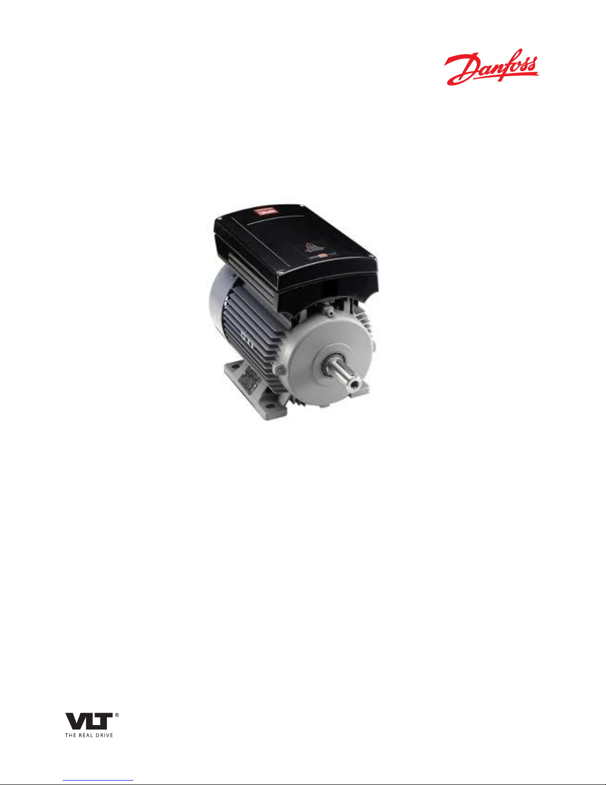
Reset
(pushbutton)
Start
Jog
Speed
reference
Terminals
1: Analogue input 6: 24 V DC supply
2: Analogue input 7: 10 V DC supply
3: Digital input 8: 0 V
4: Digital input 9: Output
5: Digital input
- Reset to be closed short time for resetting fault trips
- Start to be closed for changing to run mode
- Jog will run at fixed speed while closed (10 Hz)
- Speed reference (0-10 V) determines speed while in
run mode
Fig. 1
Factory setting
1 Mechanical installation
Install the FC motor with adequate access for routine
maintenance. Adequate space, particularly at the fan
inlet (50 mm), is necessary to facilitate airflow.
Where several FC motors are installed in close proximity,
care must be taken to ensure that there is no
recirculation of exhausted warm air.
NB!:
Ambient temperature
To avoid the FC part getting overheated, the
ambient temperature is not to exceed 40 °C and
the 24-hour average temperature is not to exceed 35
°C. If the ambient temperature is in the range of 40 °C 55 °C, a reduction of the service life of the FC part is to
be expected. For further information, please see the
section on derating in the Design Guide.
NB!:
Bearings
Ball and roller bearings are despatched from the
works fully charged with grease. Shielded
bearings have sufficient grease for an operating life of at
least two years in normal ambient temperatures,
providing there is little or no leakage.
Tapping of fitments onto the motor shaft,
with a hammer or mallet, causes bearing
damage. This results in increased bearing
noise and a significant reduction in bearing
life.
Motors type B14 & B34 mounting
1) Max length of the fixing bolts / screws
penetrating the B14 flange:
FCM 305-307 (frame 80) = 12.0mm
FCM 311-315 (frame 90) = 10.0mm
FCM 322-330 (frame 100) = 10.0mm
FCM 340 (frame 112) = 10,0mm
FCM 355-375 (frame 132) = 12.0mm
2) The following precautions must be taken:
a) A non-setting jointing and sealing compound must
be used to seal the bolt / screw threads in the motor
flange.
b) A soft copper washer must be inserted
underneath the bolt / screw head.
c) The joint face between the motor flange and the
mounting must be sealed using non-setting jointing
and sealing compound.
For B34 types where it is only foot mounted, the flange
is not used. Then the bolts should be fitted in
accordance with parts a) & b) of item 2 to maintain the
IP55.
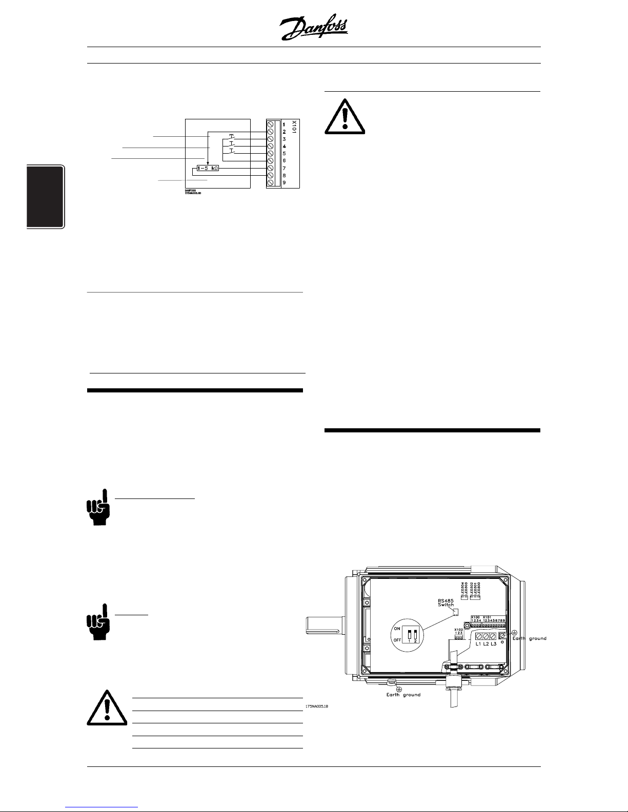
2 Electrical connections
Remove the inverter box cover, which is held by four
screws, to obtain access to the terminals.
Remove the detachable terminal plugs from the terminal
blocks X100 and X101 to obtain access to the mains
terminals.
Lift only the corner of the black plastic cover by the
cable entries to expose the mains terminals L1, L2 and L
3
(see fig. 2).
The control cables must be screened cables.
Fig. 2
Phone: 800.894.0412 - Fax: 888.723.4773 - Web: www.clrwtr.com - Email: info@clrwtr.com
Page 3

VLT® DriveMotor FCM 300 Quick Setup
ENGLISH
NB!:
Do not lift or remove the entire plastic cover.
The voltage on the FC motor is dangerous
and may lead to material damage, serious
injury or it may be fatal.
NB!:
Mains terminals L1, L2 and L3:
Make sure that your mains supply corresponds
to the voltage required by the FC motor (see
inverter label), TT and NT mains .
Connect the three mains phases to terminals L1, L2 and
L
3
and the earth to the separate terminal provided.
Tightening Torques
L1, L2, L
3
FCM 305-340 0,5-0,6 Nm
L1, L2, L
3
FCM 355-375 1,2-1,5 Nm
Earth ground FCM 305-375 3,4 Nm
Fixed wires:
Rated temperature for fixed wires min. 60° C or 140° F.
Use copper conduction only.
NB!:
You cannot change the rotation direction of the
motor by shifting around the phases. The direct-
ion of rotation is clockwise by default. Another
direction of rotation can be programmed, see the Design
Guide.
Prefuses Max.
UL
1)
FCM 305-322 10A
FCM 330-340 15A
FCM 355-375 25A
IEC
1)
FCM 305-375 25A
1)
Type gG prefuses must be used. If you want to maintain
UL/cUL you must use prefuses of the type Bussmann KTS-R
500 V or Ferraz Shawmut, type ATMR (max. 30A). The fuses
must be placed for protection in a circuit that is capable of
supplying a maximum of 100,000 amps RMS (symmetrical),
500 V maximum.
Control terminals
For information on terminal blocks X100, X101 and
X102, please see table A, B and C.
X100: Terminal block for data communication
Terminal Function
No.
1 P RS 485 for connection to
2 N RS 485 bus or PC
3 5 V DC
Supply for RS 485 bus
4 0 V DC
Table A
X101: Terminal block for analog/digital control signals
Terminal Function Example
No.
1 Analog input (0-20 mA) Feedbacksignal
2 Analog (0-10 V)/ Hastigheds-
digital input 2 reference
3 Digital input (or pulse) 3 Reset
4 Digital input
(or precise stop) 4
Start
5 Digital input (other) 5
Jog
(fixed speed)
6 24 V DC supply for digital
inputs (max 50 mA)
7 10 V DC supply
for potentiometer
(max. 15 mA)
8 0 V for terminals 1-7 and 9
9 Analog (0-20 mA)
digital output
Fault indication
Table B
X102: Terminal block for relay output
Terminal Function
No.
1-2 Make (normally open)
1-3 Brake (normally closed)
Table C
RS 485 switch
For terminating an RS 485 interface serial
communication, the bus must be terminated by a
resistor network at both ends. This is provided by setting
both switches to ON.
LEDs
The FC motor has five LEDs which indicate the status of
the FC motor:
LED 300 (red): Fault trip
LED 301 (yellow): Warning
LED 302 (green): Power on
LED 303-304 (green): Communication
EMC-correct installation
The control cables must be screened cables to ensure
EMC-correct electrical installation.
Connect the screen to earth at both ends.
Avoid installation with twisted screen ends (pigtails),
since this ruins the screening effect at high frequencies.
Use cable clamps instead.
Phone: 800.894.0412 - Fax: 888.723.4773 - Web: www.clrwtr.com - Email: info@clrwtr.com
Page 4

MG.03.A3.62 – VLT is a registered Danfoss trademark8
VLT® DriveMotor FCM 300 Quick Setup
ENGLISH
3 Start the FC motor
Connect mains. LED 302 (green) lights up to indicate
that the power is on. In Profibus versions, LED 303 will
flash. For further information on Profibus, please see the
Profibus manual.
Connect terminal 4 and 6 to the start button (see fig. 1).
Connect terminal 2, 7 and 8 to the potentiometer (see
fig. 1).
Use the start button to start the FC motor and adjust the
speed by means of the potentiometer.
Warning
The voltage on the FC motor is dangerous
when the motor is connected to mains.
Incorrect installation of the FC motor may
lead to material damage or serious injury
or it may be fatal.
4 Mount the inverter box cover.
Fastening torque: 2.2 - 2.4 Nm
SafetySafety
SafetySafety
Safety
All operations must be carried out by
appropriately trained personnel.
Use all lifting facilities provided e.g. both
lifting points, if fitted, or single lifting point, if
fitted*.
Vertical lifting - Prevent uncontrolled rotation.
Lift machine - Do not lift other equipment with motor
lifting points only.
Before installation check for fan cover damage, shaft
damage, foot/mounting damage, and loose
fasteners. Check nameplate details.
Ensure level mounting surface, balanced mounting,
not misaligned.
Gaskets, and/or sealants, and guards must be
correctly fitted.
Correct belt tension.
Please observe derating rules, see Design Guide
* Note: maximum hand lift is 20 kg below shoulder, but
above ground level.
Max. weights:
- Frame size 80: 15 kg
- Frame size 90 & 100: 30 kg
- Frame size 112: 65 kg
The voltage on the FC motor is dangerous
when the motor is connected to mains.
Incorrect installation of the FC motor may
lead to material damage or serious injury or
it may be fatal.
Consequently, the instructions in this Quick Setup as
well as national and local rules and safety regulations
must be complied with.
Touching the electrical parts may be fatal, even after the
mains supply has been disconnected.
Wait at least 4 minutes.
- Installation must be fused and isolated correctly.
- Covers and cable entries must be fitted
NB!:
It is the user's or certified electrician's
responsibility to ensure correct earthing and
protection in accordance with applicable national
and local requirements and standards.
Safety regulations
1. The FC motor must be disconnected from mains if
repair work is to be carried out. Check that the mains
supply has been disconnected and that the
necessary time has passed (4 minutes).
2. Correct protective earthing of the equipment must
be established, the user must be protected against
supply voltage, and the motor must be protected
against overload in accordance with applicable
national and local regulations.
In UL/cUL applications ETR provides class 20,
overload protection in accordance with the NEC
®
.
RCD's (ELCB relays), multiple protective earthing or
earthing can be used as extra protection, provided
that local safety regulations are complied with.
In case of an earth fault, a DC content may develop
in the fault current.
If RCD's are used, local regulations must be
observed. Relays must be suitable for protection of
3-phase equipment with a bridge rectifier and for a
brief discharge on power-up.
Phone: 800.894.0412 - Fax: 888.723.4773 - Web: www.clrwtr.com - Email: info@clrwtr.com
Page 5

VLT® DriveMotor FCM 300 Quick Setup
ENGLISH
■■
■■
■ What if the motor does not start?
- Make sure no parameters have been changed from
initial delivery status (factory setting). Use the Local
Control Panel or serial port to reset to factory setting.
- Make sure no STOP command have been issued by
the optional control panel keyboard (local stop)
Control Panel STOP can only be restarted by the
Control Panel START button.
- Remove lid to check the Light Emitting Diodes visible
through a hole in the inside isolation cover (See the
drawing), follow table below.
Warning:
Extreme care must be taken when
operating the unit with open lid.
Green Yellow Red Action
LED 302LED 302
LED 302LED 302
LED 302
LED 301LED 301
LED 301LED 301
LED 301
LED 300LED 300
LED 300LED 300
LED 300
OFF OFF OFF Apply power
(see point 2)(see point 2)
(see point 2)(see point 2)
(see point 2)
ON OFF OFF Apply start and
reference signals ,
(see figur(see figur
(see figur(see figur
(see figur
e 1 ande 1 and
e 1 ande 1 and
e 1 and
point 3)point 3)
point 3)point 3)
point 3)
ON OFF ON Apply reset signal
according to figure 1.
ON ON ON Switch off power until
all LED's have turned
off. After power on
reset signal is required.
This Quick Setup gives information on safety and helps
you to get your FCM 300 Series motors installed and
running in factory setting, see fig. 1.
For additional information, please see the Design
Guide.
Tools for installation
1 cross-point screwdriver
1 large screwdriver
1 small screwdriver
Min. 2 glands:
Gland sizes
FCM 305-330 3 x M20 x 1.5 mm
FCM 340-375 1 x M25 x 1.5 mm,
2 x M20 x 1.5 mm
1 mains cable
1 control cable
Max. cable cross section
Mains supply cable 4.0 mm2/10 AWG
Control cable 1.5 mm2/16 AWG
Serial communication cable 1.5 mm2/16 AWG
For further information see the design guide and/or
PROFIBUS manual.
3. The earth leakage currents are higher than 3.5
mA (approx. 7 mA). This means that the FC motor
requires a fixed, permanent installation as well as
reinforced protective earthing.
■ Warning against unintended start
1. The motor can be brought to a stop by means
of digital commands, bus commands, or
references, while the FC motor is connected to
mains. If personal safety considerations make it
necessary to ensure that no unintended start
occurs,
these stop functions are not sufficient.
2. While parameters are being changed, the motor
may start.
3. A motor that has been stopped may start if
faults occur in the electronics of the FC motor, or if
a temporary overload or a fault in the supply
mains or the motor connection ceases.
Phone: 800.894.0412 - Fax: 888.723.4773 - Web: www.clrwtr.com - Email: info@clrwtr.com
 Loading...