

Danfoss VLT FCD 303, VLT FCD 322, VLT FCD 305, VLT FCD 330, VLT FCD 335 Operating Instructions Manual
...Page 1

■ Contents
VLT®FCD Series
Introduction to FCD 300
Software version ...................................................................................................... 3
High voltage warning ............................................................................................... 4
These rules concern your safety ............................................................................... 4
Warning against unintended start ............................................................................. 4
................................................................................ 3
Installation ........................................................................................................... 7
Mechanical measurements ..................................................................................... 7
Mechanical dimensions, FCD, motor mounting ........................................................ 7
Mechanical dimensions, stand alone mounting ........................................................ 7
Mechanical installation ............................................................................................. 8
General information about electrical installation ...................................................... 10
Electronics purchased without installation box ....................................................... 10
EMC-correct electrical installation .......................................................................... 11
Diagram ................................................................................................................. 13
RFI switches J1, J2 ................................................................................................ 13
Location of terminals .............................................................................................. 14
Mains connection ................................................................................................... 16
Pre-fuses ................................................................................................................ 16
Motor connection ................................................................................................... 16
Direction of motor rotation ..................................................................................... 16
Mains and motor connection with service switch ................................................... 16
Connection of HAN 10E motor plug for T73 .......................................................... 16
Parallel connection of motors ................................................................................. 17
Motor cables .......................................................................................................... 17
Motor thermal protection ....................................................................................... 17
Brake resistor ......................................................................................................... 17
Control of mechanical brake .................................................................................. 18
Electrical installation, control cables ....................................................................... 19
Connection of sensors to M12 plugs for T53, T63, T73 ........................................ 20
Electrical installation, control terminals ................................................................... 21
PC communication ................................................................................................ 21
Relay connection ................................................................................................... 21
Connection examples ............................................................................................ 22
Programming, FCD 300 ............................................................................... 26
The LCP 2 control unit, option ............................................................................... 26
Parameter selection ............................................................................................... 29
Operation & Display ............................................................................................... 31
Setup configuration ................................................................................................ 31
Load and Motor ..................................................................................................... 39
DC Braking ............................................................................................................ 43
Motortype, par, 147 - FCD 300 ............................................................................. 48
References & Limits ............................................................................................... 49
Handling of references ........................................................................................... 49
Reference function ................................................................................................. 53
Inputs and outputs ................................................................................................. 57
Special functions .................................................................................................... 66
PID functions ......................................................................................................... 68
Handling of feedback ............................................................................................. 70
Serial communication for FCD 300 ........................................................................ 77
MG.04.B7.02 - VLT is a registered Danfoss trademark
1
Page 2

VLT®FCD Series
Control Word according to FC protocol ................................................................. 81
Status Word according to FC Profile ...................................................................... 83
Fast I/O FC-profile ................................................................................................. 84
Control word according to Fieldbus Profile ............................................................ 84
Status word according to Profidrive protocol ......................................................... 85
Serial communication ............................................................................................. 88
Technical functions ................................................................................................ 96
All about FCD 300 ......................................................................................... 101
Service ................................................................................................................. 101
Warnings/alarm messages ................................................................................... 102
Warning words, extended status words and alarm words ................................... 105
Aggressive environments ...................................................................................... 106
Cleaning ............................................................................................................... 106
Derating for running at low speed ........................................................................ 107
Galvanic isolation (PELV) ...................................................................................... 107
Derating for air pressure ...................................................................................... 108
Emission test results according to generic standards and PDS product standard 108
General technical data ......................................................................................... 109
Ordering form - FCD 300 ..................................................................................... 115
Technical data, mains supply 3 x 380 - 480 V ..................................................... 116
Available literature ............................................................................................... 117
Supplied with the unit ........................................................................................... 117
Factory Settings ................................................................................................... 118
Index .................................................................................................................... 125
2
MG.04.B7.02 - VLT is a registered Danfoss trademark
Page 3
VLT®FCD Series
FCD 300 Series
Operating instructions
Software version: 1.5x
These operating instructions can be used for all FCD 300
Series frequency converters with software version 1.5x.
The software version number can be seen from parameter
640 Software version no.
195NA195.12
300
Introduction to FCD
NB!:
Indicates something to be noted by the reader.
tes a general warning.
Indica
Indicates a high-voltage warning.
MG.04.B7.02 - VLT is a registered Danfoss trademark
3
Page 4
VLT®FCD Series
■High voltage warning
The voltage of the frequency converter
is dangerous whenever the converter
is connected to mains. Incorrect fitting
of the motor or frequency converter may cause
damage to the equipment, serious injury or death.
Consequently, it is essential to comply with the
instructions in this manual as well as local and
national rules and safety regulations.
■These rules concern your safety
1. The frequency converter must be disconnected from
the mains if repair work is to be carried out. Check
that the mains supply has been disconnected
and that the prescribed time has passed before
removing the inverter part from the installation.
2. The [STOP/RESET] key on the optional control
panel does not disconnect the equipment from
mains and is thus not to be used as a safety switch.
3. The unit must be properly connected to the
earth, the user must be protected against the
supply voltage and the motor must be protected
against overloading pursuant to prevailing
national and local regulations.
4. The earth leakage currents are higher than 3.5 mA.
5. Protection against motor overload is not included
in the factory setting. If this function is required,
set parameter 128 Motor thermal protection to
data value ETR trip or data value ETR warning.For
the North American market: The ETR functions
provide overload protection of the motor, class
20, in accordance with NEC.
■Warning against unintended start
1. The motor can be brought to a stop by
means of digital commands, bus commands,
references or a local stop, while the frequency
converter is connected to mains. If personal
safety considerations make it necessary to
ensure that no unintended start occurs, these
stop functions are not sufficient.
2. While parameters are being changed, the
motor may start. Consequently, the stop
key [STOP/RESET] on the optional control
panel must always be activated, following
which data can be modified.
3. A motor that has been stopped may start if faults
occur in the electronics of the frequency converter,
or if a temporary overload or a fault in the supply
mains or the motor connection ceases.
Warning:
It can be extremely dangerous to touch the electrical parts
even when the AC line supply has been disconnected.
For FCD 300: wait at least 4 minutes.
195NA194.10
4
MG.04.B7.02 - VLT is a registered Danfoss trademark
Page 5
■The decentral concept
The FCD 300 Adjustable speed drive is designed
for decentral mounting, e.g. in the food and
beverage industry, in the automotive industry, or
for other material handling applications.
With the FCD 300 it is possible to utilize the cost saving
potential by placing the power electronics decentrally,
and thus make the central panels obsolete saving
cost, space and effort for installation and wiring.
VLT®FCD Series
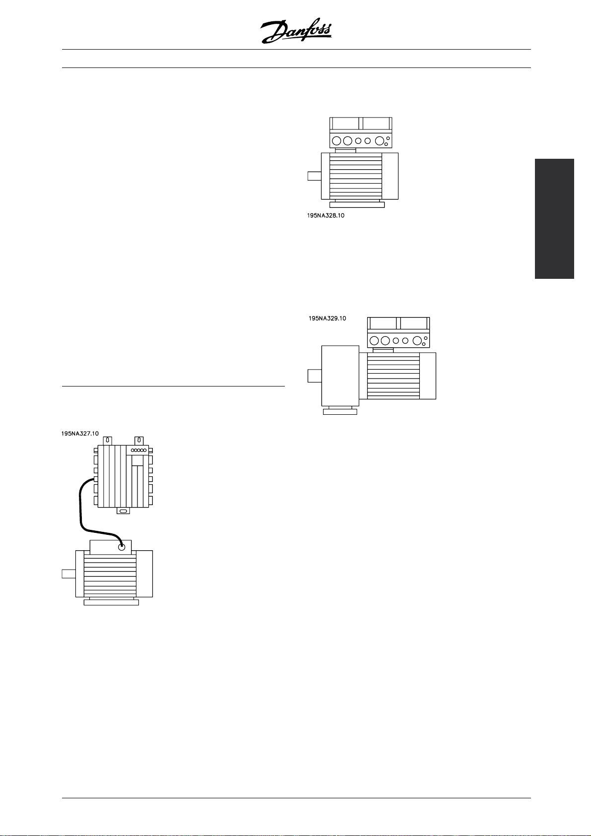
2. Mounted directly onthe motor ("motor-mounted")
The unit is flexible in its mounting options for as
well stand alone mounting and motor mounting. It
is also possible to have the unit pre-mounted on
a Danfoss Bauer geared motor (3 in one solution).
Thebasicdesignwithaplugableelectronicpartand
a flexible and "spacious" wiring box is extremely
servicefriendly and easy to change electronics
without the need for unwiring.
The FCD 300 is a part of the VLT frequency converter
family, which means similar funcionality, programming,
and operating as the other family members.
■Flexible installation options
1. Stand alone close to the motor ("wall-mounted")
300
• Fair choice of motor brands
• No need for screened motor cable
Introduction to FCD
3. "Pre-mounted" on Danfoss Bauer
geared motors
• A fixed combination of motor and electronics
supplied by one supplier
• Easy mounting, only one unit
• No need for screened motor cable
• Clear responsibility regarding the complete solution
Astheelectronicpartsarecommon-samefunction
of terminals, similar operation and similar parts
and spare parts for all drives - you are free to
mix the three mounting concepts.
• Free choice of motor brand
• Easy retrofitting to existing motor
• Easy interfacing to motor (short cable)
• Easy access for diagnosis and optimal serviceability
MG.04.B7.02 - VLT is a registered Danfoss trademark
5
Page 6
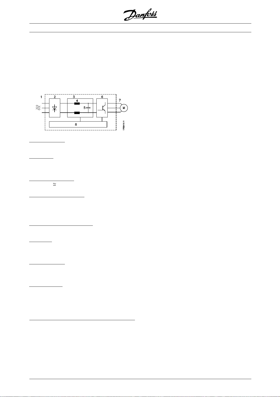
■Control principle
A frequency converter rectifies AC voltage from
the mains supply into DC voltage, following which
it changes this voltage to an AC voltage with
variable amplitude and frequency.
The motor thus receives a variable voltage and
frequency, which enables infinitely variable speed
control of three-phase, standard AC motors.
1. Mains voltage
3 x 380 - 480 V AC, 50 / 60 Hz.
2
. Rectifier
Three-phase rectifier bridge which rectifies AC
voltage into DC voltage.
VLT®FCD Series
3
. Intermediate circuit
DC voltage √2 x mains voltage [V].
4
. Intermediate circuit coils
Evens out the intermediate circuit current and
limits the load on mains and components (mains
transformer, cables, fuses and contactors).
. Intermediate circuit capacitor
5
Evens out the intermediate circuit voltage.
6
. Inverter
Converts DC voltage into a variable AC voltage
withavariablefrequency.
. Motor voltage
7
Variable AC voltage depending on supply voltage.
Variable frequency: 0.2 - 132 / 1 - 1000 Hz.
8
. Control card
Here is the computer that controls the inverter
which generates the pulse pattern by which
the DC voltage is converted into variable AC
voltage with a variable frequency.
6
MG.04.B7.02 - VLT is a registered Danfoss trademark
Page 7
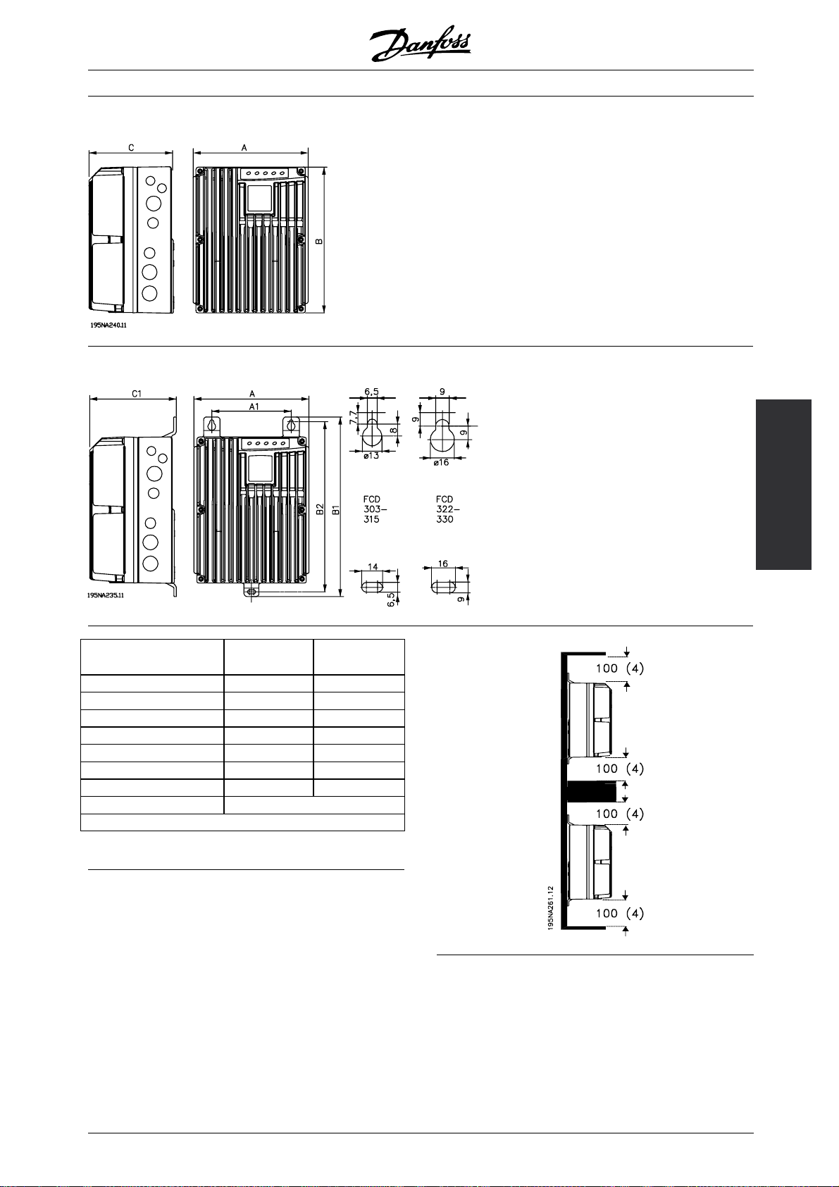
■Mechanical dimensions, FCD, motor mounting
■Mechanical dimensions, stand alone mounting
VLT®FCD Series
Mechanical dimensions inmmFCD 303-315 FCD 322-335
A 192 258
A1 133 170
B 244 300
B1 300 367
B2 284 346
C 142 151
C1 145 154
Cable Gland sizes M16, M20, M25 x 1.5 mm
Space for cable inlets and service switch handle 100-150 mm
■Spacing for mechanical installation
All units require a minimum of 100 mm air from other
components above and below the enclosure.
Installation
MG.04.B7.02 - VLT is a registered Danfoss trademark
7
Page 8
VLT®FCD Series
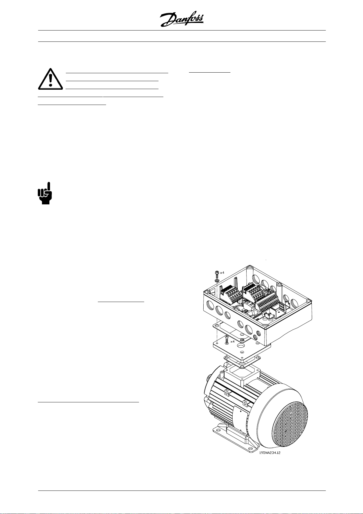
■Mechanical installation
Please pay attention to the requirements
that apply to integration and remote
mounting. These must be complied
with to avoid serious injury or damage, especially
when installing large units.
The FCD 300 consists of two parts: The installation
part and the electronics part.
The two parts must be separated, and the installation
part is to be mounted first. After wiring, the electronics
is to be fixed to the installation part by the attached
6 screws. For compressing the gasket the screws
must be tightened with 2-2.4 Nm, tighten both centre
screws first, thereafter the 4 corner srews "cross over".
NB!:
Do not switch on the mains before the
6 screws are tightened.
The FCD 300 can be applied as following:
- Stand alone mounted close to the motor
- Motor mounted
or might be delivered pre mounted on a Danfoss
Bauer (geared) motor. Please contact the Danfoss
Bauer sales organisation for further information.
See Dimensional Drawings.
otor mounting
M
The installation box should be mounted on the
surface of the motor frame, typically instead of the
motor terminal box. The motor/geared motor may
be mounted with the shaft vertically or horizontally.
The unit mustnot be mounted upside down (the heat
sink pointing down). The cooling of the electronics is
independent on the motor cooling fan. For mounting
directly on Danfoss Bauer geared motors no adaption
plate is necessary. For motor mounting (non Danfoss
Bauer motors), an adaptor plate should usually be
applied. For that purpose a neutral plate incl gasket
and screws for attaching to the installation box is
available. The appropriate drillings and gasket for the
motor housing are applied locally. Please make sure,
that the mechanical strength of the mounting screws
and the threads are sufficient for the application. The
specified resistance against mechanical vibrations
does not cover the mounting onto a non Danfoss
Bauer motor, as the stability of the motor frame
and threads are outside Danfoss Drive’s control and
responsibility and the same applies to the enclosure
class. Please be aware, that the frequency converter
may not be used to lift the motor/geared motor.
The frequency converter is cooled by means of air
circulation. For the unit to be able to release its
cooling air, the minimum free distance above and
below the unit must be m
the unit from overheating, it must be ensured that the
ambient temperature does not rise above the max.
temperature stated for the frequency converter and
that the 24-hour average temperature is not exceeded.
The max. temperature and 24-hour average can
be seen in Ge neral technical data. If the ambient
temperature is higher, derating of the frequency
converter is to be carried out. See Derating for
ambient temperature. Pleasenotethattheservicelife
of the frequency converter will be reduced if derating
for ambient temperature is not considered.
tand alone mounting ("wall mounting")
S
For best cooling the unit should be mounted vertically,
however where space limitations require it, horizontal
mounting is allowable. The integrated 3 wall mounting
brackets in the wall mounting version can be used
for fixing the installation box to the mounting surface,
keeping a distance for possible cleaning between
the box and the mounting surface. Use the three
supplied washers to protect the paint.
inimum 100 mm.Toprotect
Bolts must be M6 for the FCD 303 - 315
and M8 for FCD 322 - 335.
8
MG.04.B7.02 - VLT is a registered Danfoss trademark
Page 9
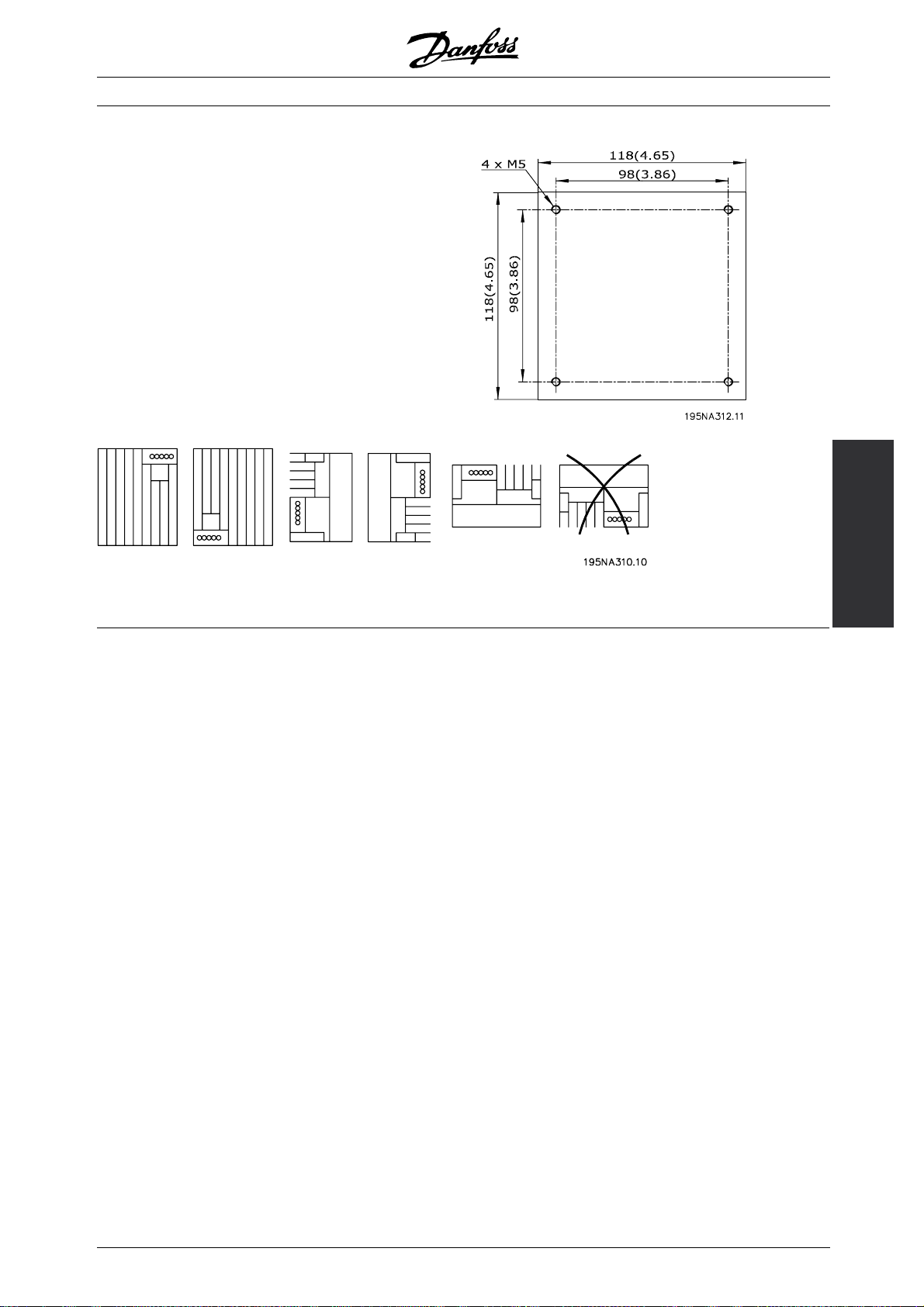
1. Prepare the adaptor plate for mounting on the motor by
drilling the fixing holes and the hole for the cables.
2. Mount the plate on the motor with the normal terminal
box gasket.
3. Knock out the 4 screw holes for mounting the adaptor
plate (outer holes).
4. Mount the terminal box onto the motor by the 4 sealing
screws and the gasket supplied.
Use the supplied star washers for securing PE
connection according to EN 60204. The screws must
be tightened with 5 Nm.
VLT®FCD Series
Universal adaptorplate
Allowed mounting positions
Installation
MG.04.B7.02 - VLT is a registered Danfoss trademark
9
Page 10
VLT®FCD Series
■General information about electrical installation
■High voltage warning
The voltage of the frequency converter
is dangerous whenever the equipment is
connected to mains. Incorrect installation
of the motor or frequency converter may cause
damage to the equipment, serious injury or death.
Comply with the instructions in this manual, as well as
national and local rules and safety regulations.
Touching the electrical parts may be fatal - even after
the equipment has been disconnected from mains:
Wait at least 4 minutes for current dissipate.
NB!:
It is the responsibility of the user or installer
to ensure correct earthing and protection in
accordance with national and local standards.
■Cables
The control cable and the mains cable should be
installed separately from motor cables to prevent
noisetransfer. Asaruleadistanceof20cmis
sufficient, but it is recommended that the distance
is as great as possible, particularly when cables are
installed in parallel over large distances.
For sensitive signal cables such as telephone or data
cables the greatest possible distance is recommended.
Please note that the required distance depends on
installation and the sensitivity of the signal cables, and
that for this reason exact values cannot be given.
■Extra protection
ELCB relays, multiple protective earthing or earthing
can be used as extra protection, provided that local
safety regulations are complied with. In the case of an
earth fault, a DC content may develop in the faulty
current. Never use an RCD (ELCB relay), type A, as
it is not suitable for DC faulty currents. If ELCB relays
are used, local regulations must be complied with.
If ELCB relays are used, they must be:
- Suitable for protecting equipment with a DC content
in the faulty current (3-phase bridge rectifier)
- Suitable for a pulse-shaped, brief discharge
on power-up
- Suitable for a high leakage current.
See also RCD Application Note MN.90.GX.02.
■High voltage test
A high voltage test can be performed by
short-circuitingterminalsU,V,W,L1,L2andL3,
and applying max. 2160 V DC in 1 sec. between
this short-circuit and PE-terminal.
■Electronics purchased without installation box
If the electronic part is purchased without the
Danfoss installation part, the earth connection
the
must be suitable for high leakage current. Use
of original Danfoss installation box or installation
kit 175N2207 is recommended.
When being placed in cable trays, sensitive cables
may not be placed in the same cable tray as t
motor cable. If signal cables run across power
cables, this is done at an angle of 90 degrees.
Remember that all noise-filled inlet
to a cabinet must be screened/armoured.
See also EMC-compliant electrical installation.
Cable glands
It must be assured that appropriat
glands needed for the environment are chosen
and carefully mounted.
■Screened/armoured cables
The screen must have low HF impe
achieved by a braided screen of copper, aluminium or
iron. Screen reinforcement intended for mechanical
protection, for example, is
installation. See also Use of EMC-correct cables.
10
not suitable for EMC-correct
and outlet cables
e cable
dance, which is
he
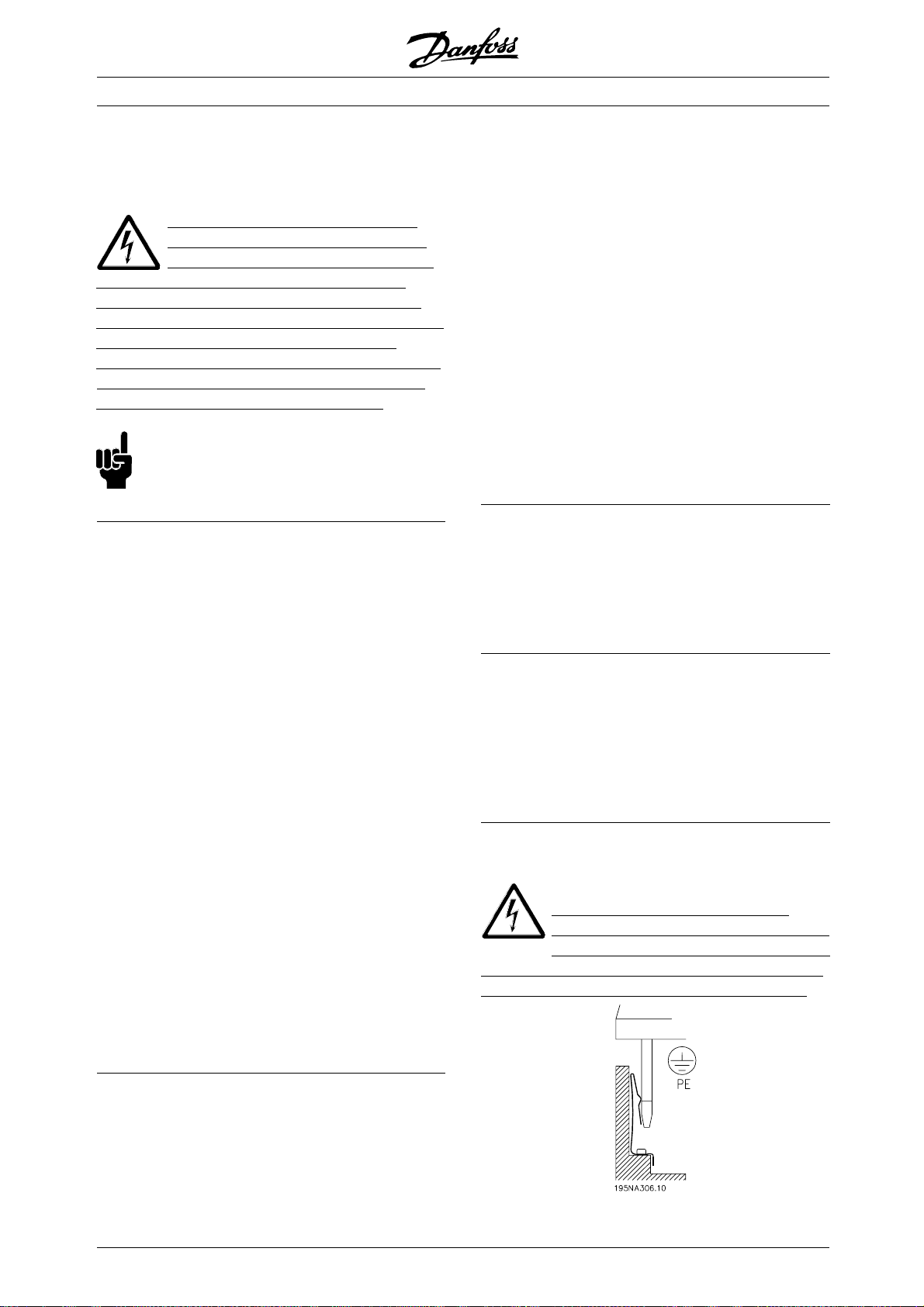
■Caution
PE connection
he metal pin in the corner(s) of the
T
electronic part and the bronze spring in the
corner(s) of the installation box are essential
for the protective earth connection. Mak
are not loosened, removed, or violated in any way.
MG.04.B7.02 - VLT is a registered Danfoss trademark
e sure they
Page 11
VLT®FCD Series
NB!:
Do not plug/unplug the electronic part with
mains voltage switched on.
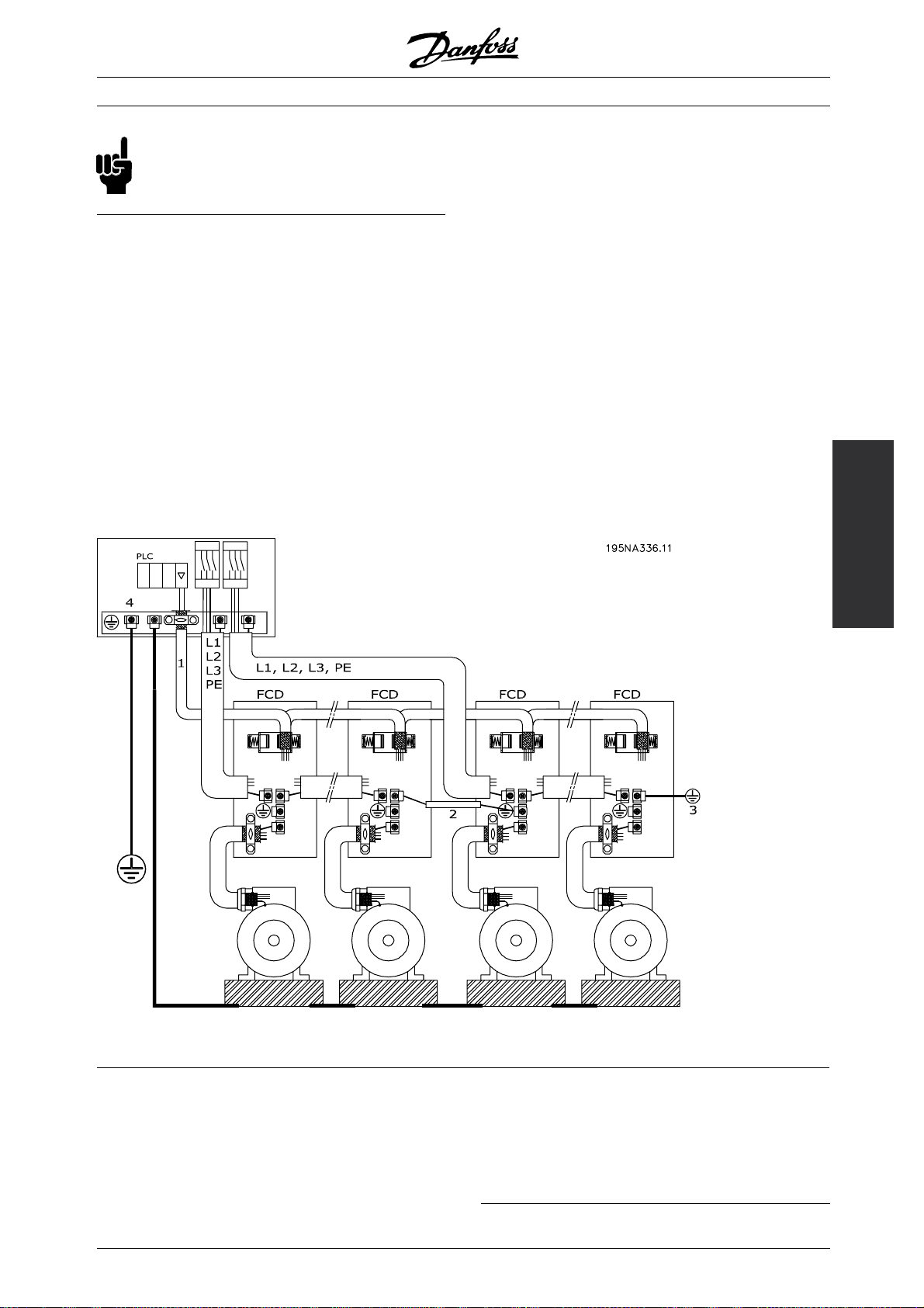
■Protective earth
The earth connection serves several purposes.
• Safety earth (Protective earth, PE)
The equipment must be properly earthed according
to local regulation. This equipment has a leakage
current > 3.5 mA AC. It must be connected to
an earth connection complying with the local
rules for high leakage current equipment.
Typically, this implies that the PE conductors
must be mechanically enhanced (minimum cross
2
section 10 mm
) or duplicated
• Noise "clamping" (high frequencies)
Stable communication between units call for
screening of the communication cables (1).
Cables must be properly attached to screen
clamps provided for that purpose.
• Equalisation of voltage potential (low frequencies)
To reduce alignment currents in the screen
of the communication cable, always apply a
short earthing cable between units that are
connected to the same communication cable (2)
or connect to an earthed frame (3).
• Potential equalization: All metal parts, where the
motors are fastened, must be potential equalized
PE connections, voltage equalising cables and the
screen of the communication cable should be
connected to the same potential (4).
Keep the conductor as short as possible and use
the greatest possible surface area.
The numbering refers to the figure.
Installation
Proper installation earthing
■EMC-correct electrical installation
General points to be observed to ensure
EMC-correct electrical installation.
- Use only screened/armoured motor cables and
screened/armoured control cables.
- Connect the screen to earth at both ends.
MG.04.B7.02 - VLT is a registered Danfoss trademark
- Avoid installation with twisted screen ends (pigtails),
since this ruins the screening effect at high
frequencies. Use cable clamps instead.
-Don’t remove the cable screen between the
cable clamp and the terminal.
11
Page 12

■ATEX correct installation
The following issues must be taken into account when
installing the FCD 300 in ATEX zone 22 environments:
• Motor must be designed, tested and certified by the
motor manufacturer for variable speed application
• Motor must be designed for Zone 22 operation.
I.e. with type of protection "tD" acc. to
EN61241-0 and -1 or EN50281-1-1.
• Motor must be provided with thermistor protection.
The thermistor protection must either be connected
to an external thermistor relay, with EC Type
Examination Certificate or compatible with
the FCD 300 thermistor input.
If the FCD 300 thermistor protection is used,
the thermistor must be wired to terminals
31a and 31b, and thermistor trip activated by
programming parameter 128 to thermistor trip
[2]. See parameter 128 for further details.
• Cable entries must be chosen for the enclosure
protection to be maintained. It must also be
ensured that the cable entries comply with the
requirements for clamping force and mechanical
strengths as described in EN 50014:2000.
• The FCD must be installed with appropriate earth
connecting according to local/national regulations.
• The installation, inspection and maintenance of
electrical apparatus for use in combustible dusts,
must only be carried out by personnel that is
trained and familiar with the concept of protection.
VLT®FCD Series
For a declaration of conformity, please consult
your local Danfoss representative.
12
MG.04.B7.02 - VLT is a registered Danfoss trademark
Page 13
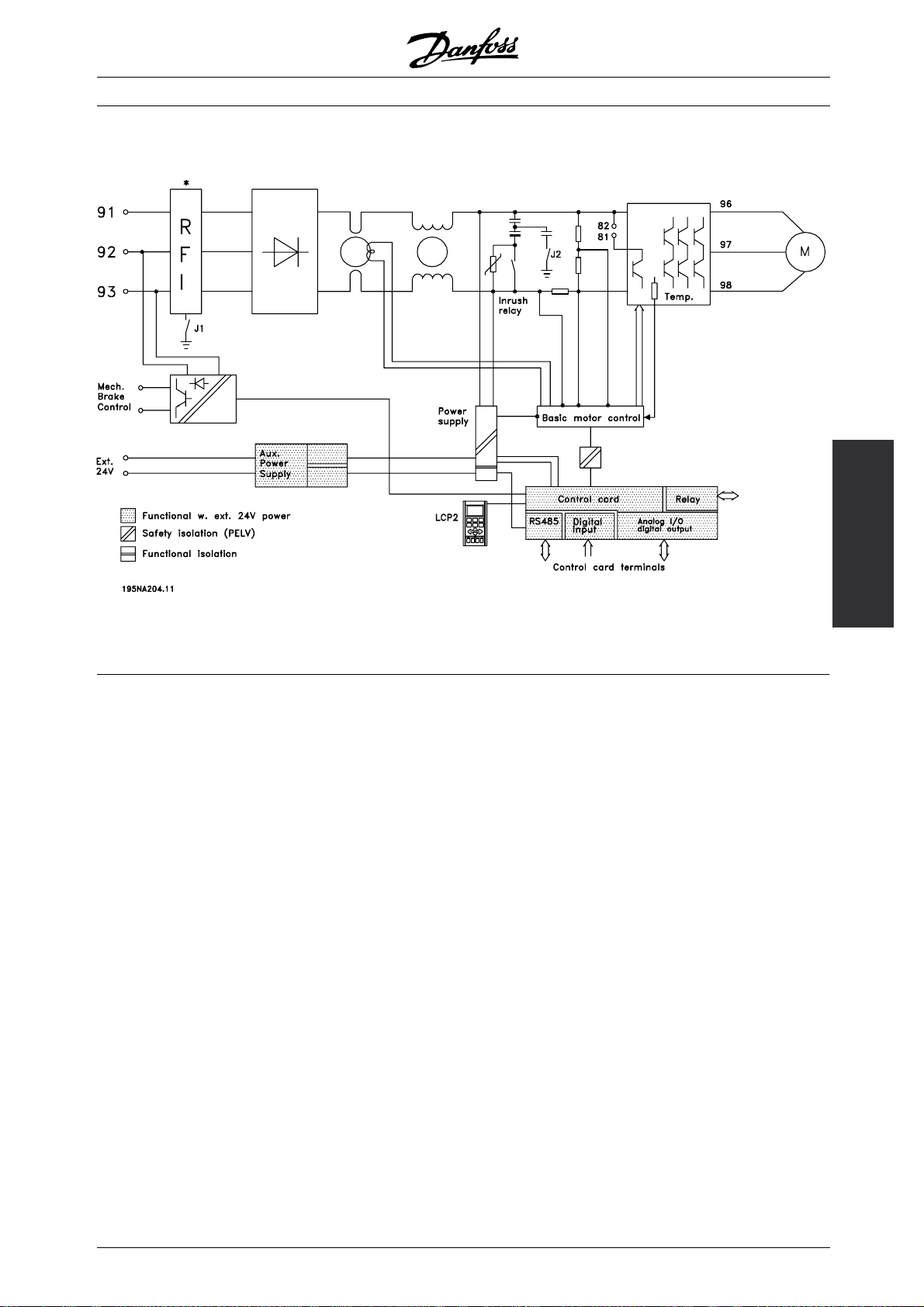
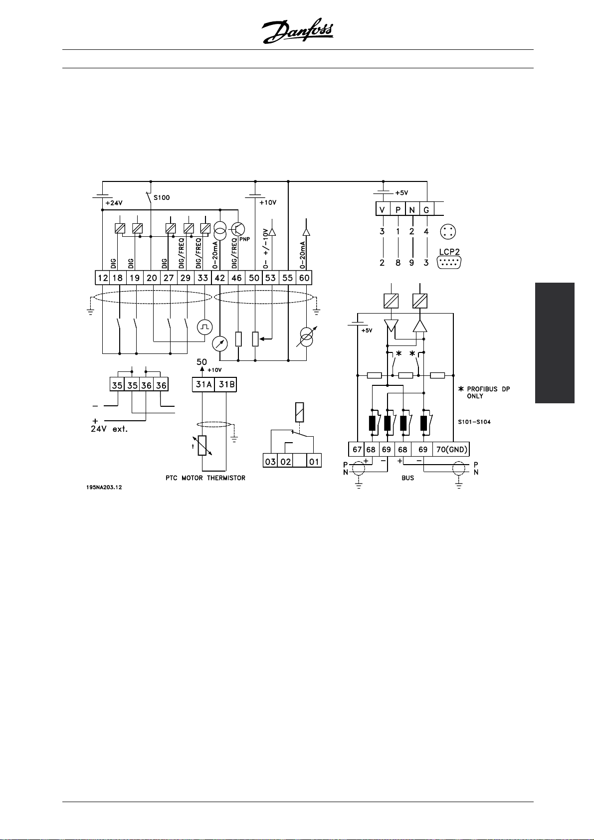
■Diagram
VLT®FCD Series
* Integrated brake and mechanical brake control
and external 24 V are options.
■RFI switches J1, J2
J1 and J2 must be removed at IT mains and
delta grounded mains with phase to earth voltage
> 300 V also during earth failure.
J1 and J2 can be removed to reduce leakage current.
Caution: No correct RFI filtering.
Installation
MG.04.B7.02 - VLT is a registered Danfoss trademark
13
Page 14

■Location of terminals
VLT®FCD Series
T11, T12, T16, T52, T56
T22, T26, T62, T66versions with service switch
14
MG.04.B7.02 - VLT is a registered Danfoss trademark
Page 15
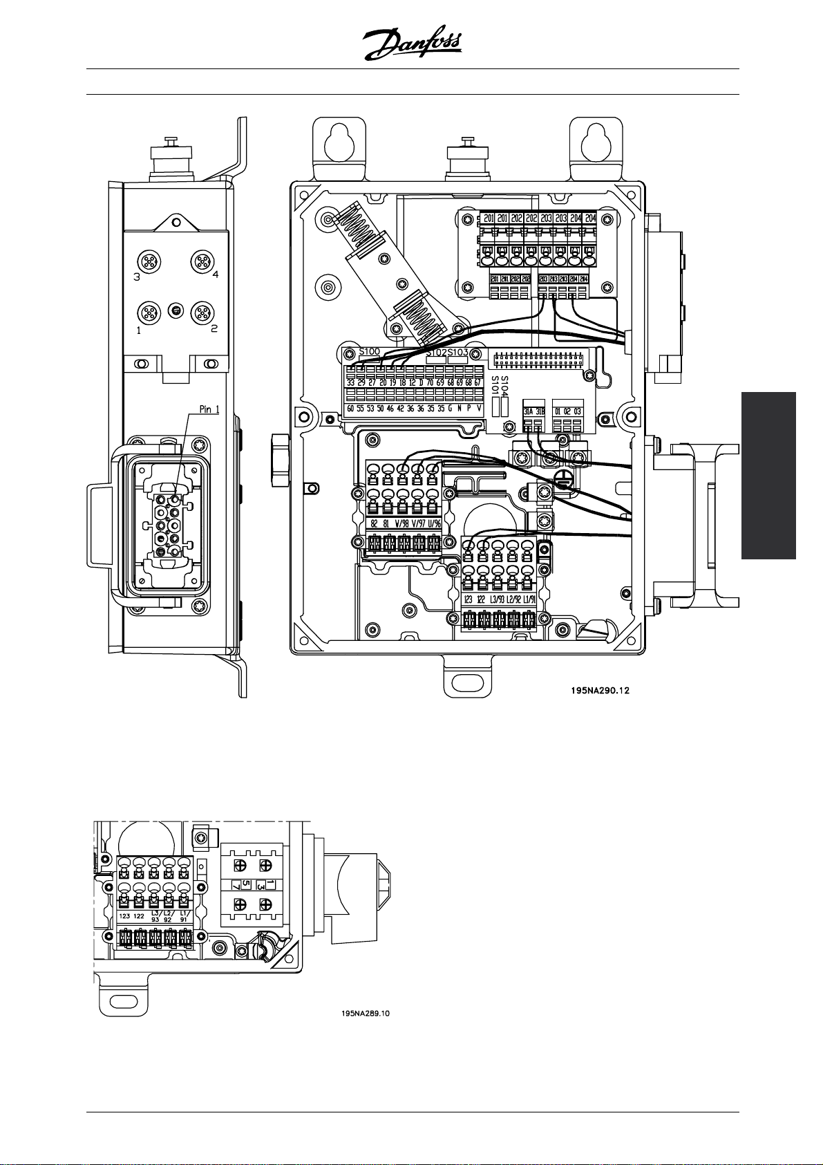
VLT®FCD Series
T73 version with motor plug and sensor plugs
Version is supplied from Danfoss with wiring as shown
Installation
versionwithserviceswitch(nomotorplug)
T63
MG.04.B7.02 - VLT is a registered Danfoss trademark
15
Page 16

VLT®FCD Series
■Mains connection
No. 91 92 93 Mains voltage 3 x 380-480 V
L1 L2 L3
PE Earth connection
NB!:
Please check that the mains voltage fits the
mains voltage of the frequency converter, which
can be seen from the nameplate.
See Technical data for correct dimensioning
of cable cross-section.
■Pre-fuses
See Technical data for correct dimensioning
of pre-fuses.
■Motor connection
Connect the motor to terminal
s 96, 97, 98.
Connect earth to PE-terminal.
No. 96 97 98 Motor voltage 0-100% of mains voltage
UVW3 wires out of motor
U1W2V1U2W1V26 wires out of motor, Delta connected
■Direction of motor rotation
The factory setting is for clockwise rotation
with the frequency converter transformer output
connected as follows:
Terminal 96 connected to U-phase.
Terminal 97 connected to V-phase.
Terminal 98 connected to W-phase.
The direction of rotation can be changed by switching
two phases on the motor terminals.
U1 V1 W1 6 wires out of motor, Star connected
U2, V2, W2 to be interconnected
separately (optional terminal block)
PE Earth connection
See Technical data for correct dimensioning
of cable cross-section.
All types of three-phase asynchronous standard
motors can be connected to a frequency converter.
Normally, small motors are star-connected (230/400
/ Y). Large motors are delta-connected (400/690
V,
/ Y). The correct connection mode and voltage
V,
can be read from the motor nameplate.
NB!:
In motors without phase insulation paper,
an LC filter should be fitted on the output
of the frequency converter.
■Mains and motor connection with service switch
16
MG.04.B7.02 - VLT is a registered Danfoss trademark
Page 17
VLT®FCD Series
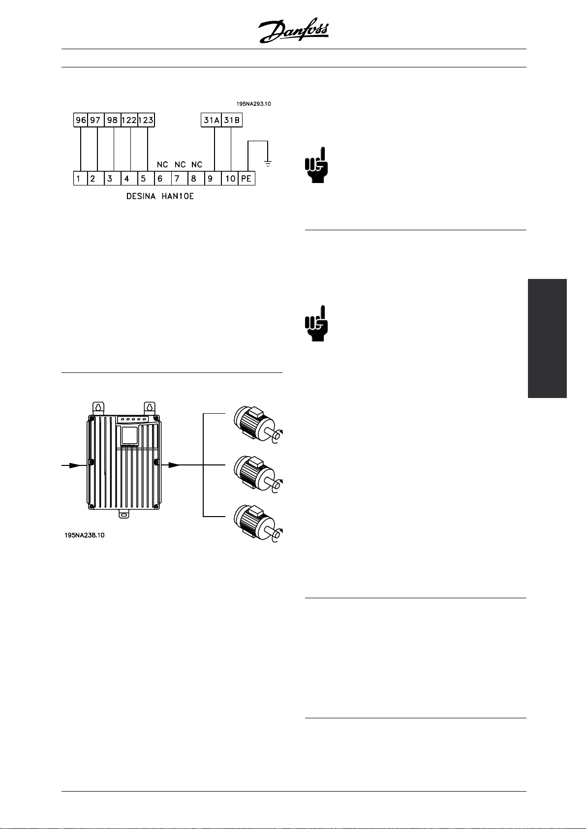
■Connection of HAN 10E motor plug for T73
HAN 10E pin no 1 - Motor phase U
HAN 10E pin no 2 - Motor phase V
HAN 10E pin no 3 - Motor phase W
HAN 10E pin no 4 - Motor brake, see Operating
Instructions MG.04.BX.YY, terminal 122
HAN 10E pin no 5 - Motor brake, see Operating
Instructions MG.04.BX.YY, terminal 123
HAN 10E pin no 9 - Motor thermistor, see Operating
Instructions MG .04.BX.YY, terminal 31A
HAN 10E pin no 10 - Motor thermistor, see
Operating Instructions MG.04.BX.YY, terminal 31B
PE = protective earth
■Parallel connection of motors
The frequency converter is able to control several
motors connected in parallel. If the motors are
to have different rpm values, use motors with
different rated rpm values. Motor rpm is changed
simultaneously, which means that the ratio between
the rated rpm values is maintained across the range.
The total current consumption of the motors is
not to exceed the maximum rated output current
for the frequency converter.
I
INV
Problems may arise at the start and at low rpm
values if the motor sizes are widely different. This
is because the small motors’ relatively high ohmic
resistance in the stator calls for a higher voltage
at the start and at low rpm values.
converter cannot be used as motor protection for
the individual motor. For this reason further motor
protection must be used, e.g. thermistors in each
motor (or an individual thermal relay).
NB!:
Parameter 107 Automatic motor tuning, AMT
cannot be used when motors are connected
in parallel. Parameter 101 Torque characteristic
must be set to Special motor characteristics [8]
when motors are connected in parallel.
■Motor cables
See Technical data for correct dimensioning of motor
cable cross-section and length. Always comply with
national and local regulations on cable cross-section.
NB!:
If an unscreened/unarmoured cable is used,
some EMC requirements are not complied with,
see EMC test results in the Design Guide.
If the EMC specifications regarding emission are
to be complied with, the motor cable must be
screened/armoured, unless otherwise stated for the
RFI filter in question. It is important to keep the motor
cable as short as possible so as to reduce the noise
level and leakage currents to a minimum. The motor
cable screen must be connected to the metal cabinet
of the frequency converter and to the metal cabinet of
the motor. The screen connections are to be made
with the biggest possible surface area (cable clamp).
This is enabled by different installation devices in
different frequency converters. Mounting with twisted
screen ends (pigtails) is to be avoided, since these
spoil the screening effect at high frequencies. If it
is necessary to break the screen to install a motor
isolator or motor relay, the screen must be continued
at the lowest possible HF impedance.
■Motor thermal protection
The electronic thermal relay in UL-approved frequency
converters has received the UL-approval for single
motor protection, when parameter 128 Motor thermal
protection has been set for ETR Trip and parameter
105 Motor current, I
has been programmed to
M, N
the rated motor current (see motor nameplate).
Installation
In systems with motors connected in parallel, the
electronic thermal relay (ETR) of the frequency
MG.04.B7.02 - VLT is a registered Danfoss trademark
17
Page 18
■Brake resistor
VLT®FCD Series
No. 81 (optional
function)
R- R+
82 (optional
function)
Brake resistor
terminals
The connection cable to the brake resistor must
be screened/armoured. Connect the screen to the
metal cabinet of the frequency conver
ter and to the
metal cabinet of the brake resistor by means of
cable clamps. Dimension the cross-section of the
brake cable to match the brake to
See chapter Dynamic Brak
ing in the Design Guide
rque.
MG.90.FX.YY for dimensionering of brake resistors.
NB!:
Please note that voltages up to 850 V
DC occur on the te
rminals.
■Control of mechanical brake
No. 122 (optional
function)
MBR+ MBR- Mechanical brake
123
(optional
function)
(UDC=0.45 X Mains
Voltage) Max 0.8 A
In lifting/lowering applications you need to be able
to control an electromagnetic brake. The brake
is controlled using the special mechanical brake
control/supply terminals 122/123.
When the output frequency exceeds the brake cut
out value set in par. 138, the brake is released if the
motor current exceeds the preset value in parameter
140. When stopping the brake is engaged when
the output frequency is less than the brake engaging
frequency, which is set in par. 139.
If the frequency converter is at alarm status
or in an overvoltage situation the mechanical
brake is cut in immediately.
If not using the special mechanical brake control/supply
terminals (122-123), select Mechanical brake control
in parameter 323 or 341 for applications with
an electromagnetic brake.
A relay output or digital output (terminal 46)
can be used. See Connection of mechanical
brake for further details.
18
MG.04.B7.02 - VLT is a registered Danfoss trademark
Page 19
VLT®FCD Series
■Electrical installation, control cables
Control cables must be screened/armoured. The
screen must be connected to the frequency converter
chassis by means of a clamp. Normally, the screen
must also be connected to the chassis of the
controlling unit (use the instructions for the unit in
question). In connection with very long control cables
and analogue signals, in rare cases depending on
the installation, 50/60 Hz earth loops may occur
because of noise transmitted from mains supply
cables. In this connection, it may be necessary
to break the screen and possibly insert a 100 nF
capacitor between the screen and the chassis.
Installation
Switches S101-104
Bus line coils, leave switches ON
MG.04.B7.02 - VLT is a registered Danfoss trademark
19
Page 20
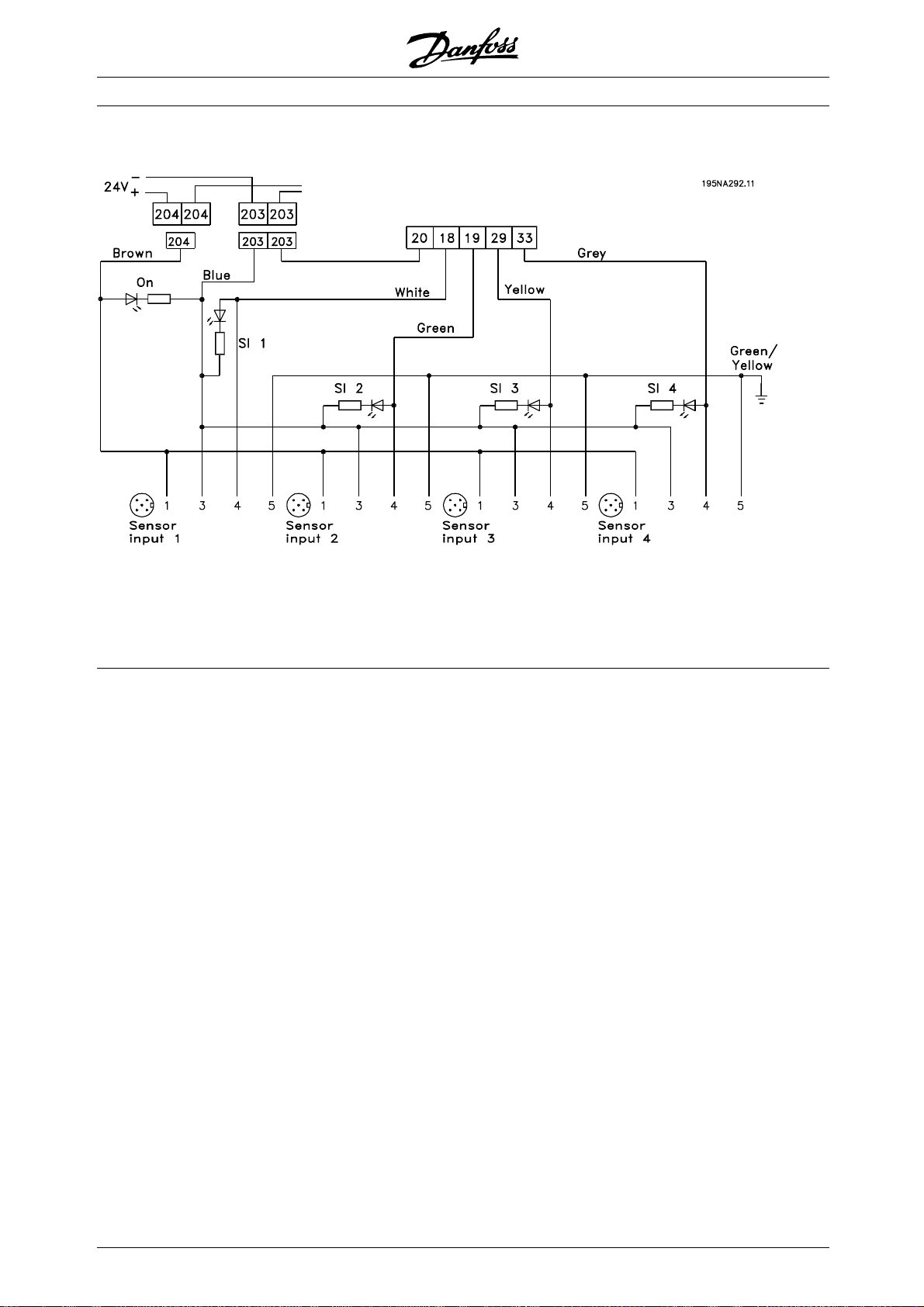
■Connection of sensors to M12 plugs for
T53, T63, T73
VLT®FCD Series
For rating specifications see the Operating Instructions
MG.04.BX.YY, digital inputs terminals 18, 19, 29, 33.
Terminals 203/204 are used for sensor supply.
Terminal 203 = common
Terminal 204 = +24 V
Terminals 201/202 can be used for a
separate 24 V supply.
20
MG.04.B7.02 - VLT is a registered Danfoss trademark
Page 21
VLT®FCD Series
■Electrical installation, control terminals
See section entitled Earthing of screened/armoured
control cables in the Design Guide for the correct
termination of control cables.
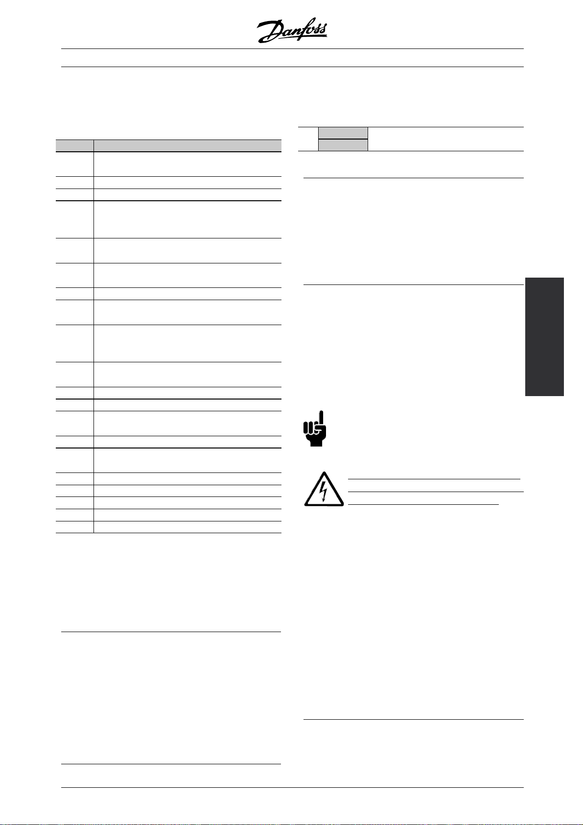
No. Function
01-03 Relay outputs 01-03 can be used for
indicating status and alarms/warnings.
12 24 V DC voltage supply.
18-33 Digital inputs.
20, 55 Common frame for input
and output terminals. Can be separated with switch
S100
31a,
31b
35 Common (-) for external 24 V control back up
36 External + 24 V control back up supply. Optional.
42 Analog output for displaying frequency,
46 Digital output for displaying status,
50 +10 V DC supply
53 Analogue voltage input 0 - +/- 10 V DC.
60 Analogue current input 0/4 - 20 mA.
67 + 5 V DC supply voltage
68, 69 Fieldbus serial communication*
70 Ground for terminals 67, 68 and 69.
D For future use
V +5V, red
P RS485(+), LCP2/PC, yellow
N RS485(-), LCP2/PC, green
G OV, blue
*SeeVLT 2800/FCM 300/
Motor thermistor
supply. Optional.
reference, current or torque.
warnings or alarms, as well as
frequency output.
voltage for potentiometer
to Profibus.
Normally this terminal is not to be used.
FCD 300 Profibus DP
V1 Operating Instructions (MG.90.AX.YY), VLT
2800/FCD 300 DeviceNet Operating Instructions
(MG.90.BX.YY) or FC
D 300 AS-interface Operating
Instructions (MG.04.EX.YY).
■Relay connection
See parameter 323 Relay output for programming
of relay output.
No. 01 - 02 1 - 2 make (normally open)
01 - 03 1-3break(normallyclosed)
■LCP 2 plug, optional
An LCP 2 control unit can be connected to a
plug which is optionally mounted in the housing.
Ordering number: 175N0131.
LCP control units with ordering number 175Z0401
are not to be connected.
■Installation of 24 Volt external supply (optional)
24 V external DC supply can be use
d as low-voltage
supply to the control card. This enables full
operation of the LCP2 and serial bus (incl. parameter
setting) without connecti
on to mains.
Please note that a warning of low voltage will
be given when 24 V DC has been connected;
however there will be n
o tripping.
NB!:
Use24VDCsupplyoftypePELVtoensure
correct galvanic isolation (type PELV) on the
control terminal
Beware of unin
s of the VLT frequency converter.
tended start of the motor, if
the mains power is applied during operation
on the external 24 V back up supply.
■Software version 1.5x
A Field bus equipped FCD shows the status Unit
ready even with bridged terminals 12-27 and cannot
be set into RUNNING mode by digital inputs alone
until one of the following parameters is set:
- Par. 502 is set to Digital input or Logic and or
- Par. 833 or 928 is set to Disable or
- Par. 678 is set to Standard version
Installation
■PC communication
Connect to terminals P and N for PC-access to single
parameters. Mot
or and field bus communication
should be stopped before performing automatic
transfer of multiple parameters.
On non-fieldb
us and Profibus variants, terminals
68 and 69 can be used provided Profibus
communication is stopped.
MG.04.B7.02 - VLT is a registered Danfoss trademark
The field bus status word at power up might be
different (typically 0603h instead of 0607h) until the
first valid control word is sent. After sending the first
valid control word (bit 10 = Data valid) the status
is exactly as in earlier software versions.
21
Page 22
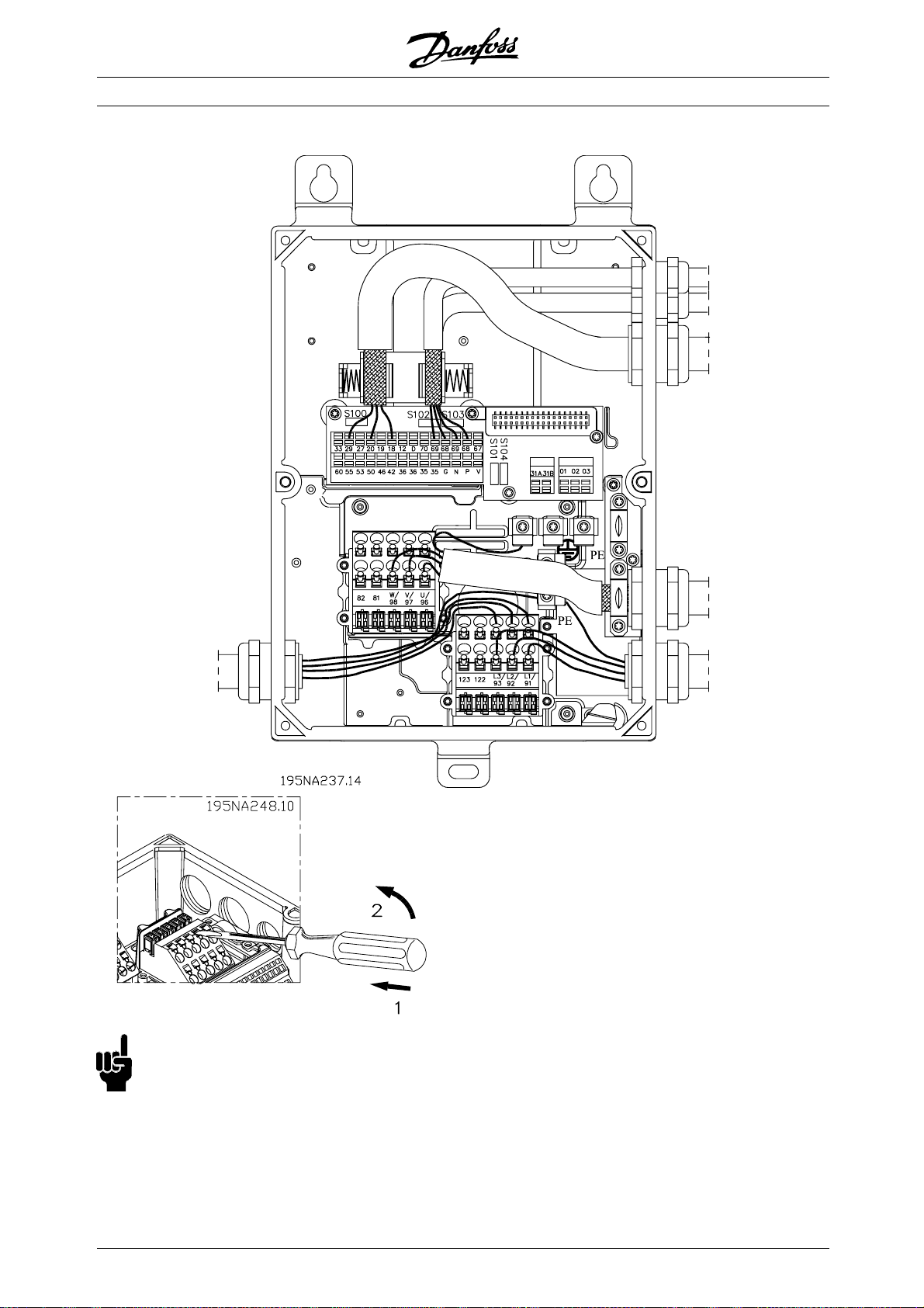
■Connection examples
VLT®FCD Series
NB!:
Avoid leading the cables over the plugs
to the electronics.
Dont loosen screw fixing the spring
for the PE connection.
22
MG.04.B7.02 - VLT is a registered Danfoss trademark
Page 23
NB!:
In the connection examples below, it should
be noted, that the Switch S100 must not be
changed from factory settings (on).
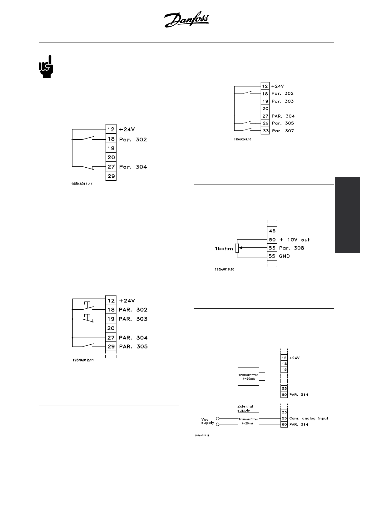
■Start/stop
Start/stop using terminal 18 and coasting
stop using terminal 27.
VLT®FCD Series
■Speed up/down
Speed up/down using terminals 29/33.
Par. 302 Digital input = Start [7]
Par. 303 Digital input = Freeze reference [14]
Par. 305 Digital input = Speed up [16]
Par. 307 Digital input = Speed down [17]
Par. 302 Digital input = Start [7]
Par. 304 Digital input = Coasting stop inverted [2]
For Precise start/stop the following settings are made:
Par. 302 Digital input = Precise start/stop [27]
Par. 304 Digital input = Coasting stop inverted [2]
■Pulse start/stop
Pulse start using terminal 18 and pulse stop
using terminal 19. In addition, the jog frequency
is activated via terminal 29.
Par. 302 Digital input = Pulse start [8]
Par. 303 Digital input = Stop inverted [6]
Par. 304 Digital input = Coasting stop inverted [2]
Par. 305 Digital input = Jog [13]
■Potentiometer reference
Voltage reference via a potentiometer.
Installation
Par. 308 Analog input = Reference [1]
Par. 309 Terminal 53, min. scaling =0Volt
Par. 310 Terminal 53, max. scaling =10Volt
■Connection of a 2-wire transmitter
Connection of a 2-wire transmitter as feedback
to terminal 60.
MG.04.B7.02 - VLT is a registered Danfoss trademark
Par. 314 Analog input = Feedback [2]
Par. 315 Terminal 60, min. scaling =4mA
Par. 316 Terminal 60, max. scaling =20mA
23
Page 24
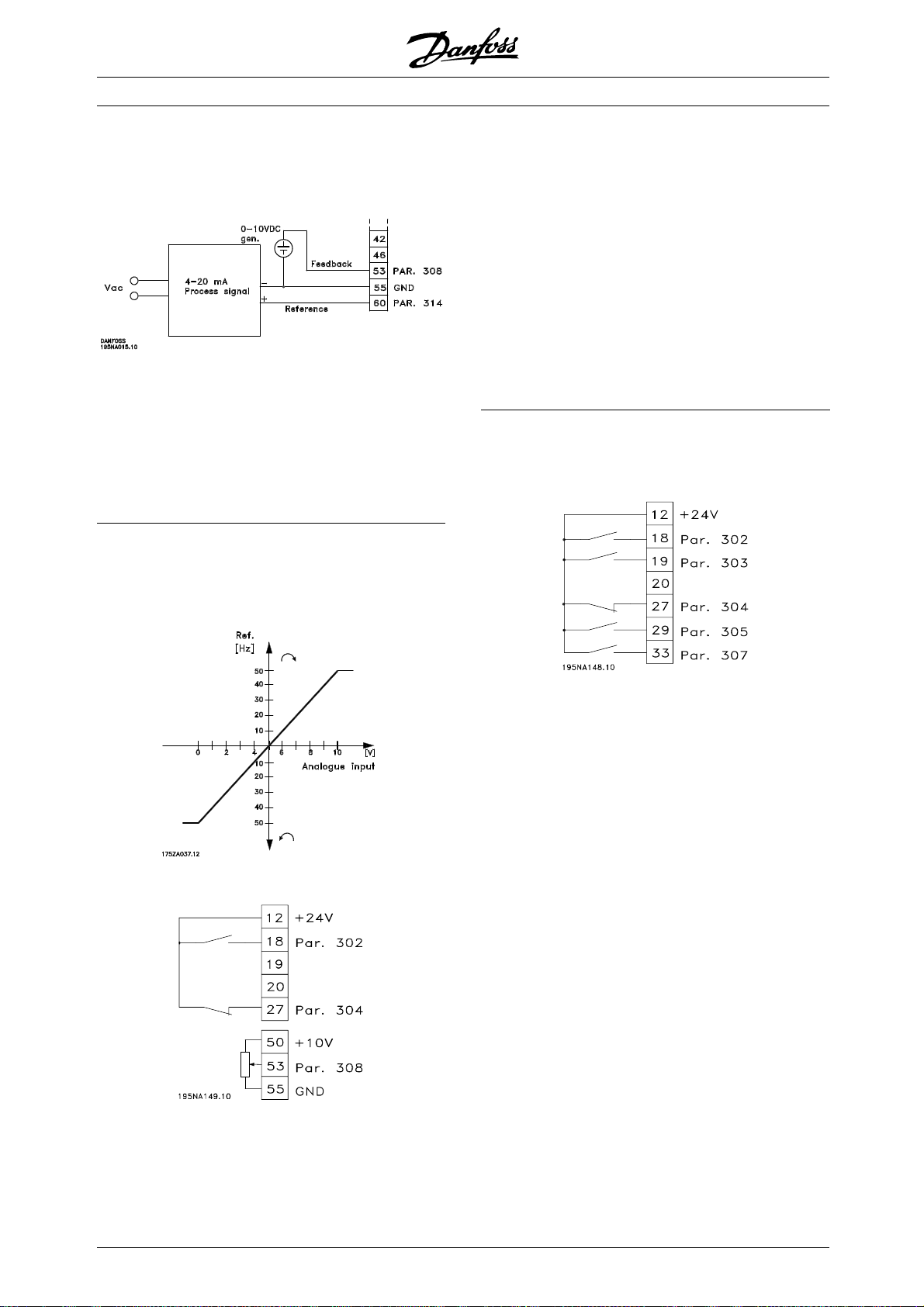
■4-20 mA reference
4-20 mA reference on terminal 60 and speed
feedback signal on terminal 53.
Par. 100 Configuration = Speedclosedloop[1]
Par. 308 Analog input = Feedback [2]
Par. 309 Terminal 53, min. scaling =0Volt
Par. 310 Terminal 53, max. scaling =10Volt
Par. 314 Analog input = Reference [1]
Par. 309 Terminal 60, min. scaling =4mA
Par. 310 Teminal 60, max. scaling =20mA
VLT®FCD Series
Par. 100 Configuration = Speed regulation
open loop [0]
Par. 200 Output frequency range = Both
directions, 0-132 Hz [1]
Par. 203 Reference range = Min. ref. - Max. ref. [0]
Par. 204 Min. reference =-50Hz
Par. 205 Max. reference =50Hz
Par. 302 Digital input = Start [7]
Par. 304 Digital input = Coasting stop inverted [2]
Par. 308 Analogue input = Reference [1]
Par. 309 Terminal 53, min. scaling =0Volt.
Par. 310 Terminal 53, max. scaling =10Volt.
■Preset references
Switch between 8 preset references via two digital
inputs and Setup 1 and Setup 2.
■ 50 Hz anti-clockwise to 50 Hz clockwise.
With internally supplied potentiometer.
Par. 004 Active Setup = Multisetup 1 [5]
Par. 204 Min. reference =0Hz
Par. 205 Max. reference =50Hz
Par. 302 Digital input = Start [7]
Par. 303 Digital input = Choice of Setup, lsb [31]
Par. 304 Digital input = Coasting stop inverted [2]
Par. 305 Digital input = Preset ref., lsb [22]
Par. 307 Digital input = Preset ref., msb [23]
Setup 1 contains the following preset references:
Par. 215 Preset reference 1 = 5.00%
Par. 216 Preset reference 2 = 10.00%
Par. 217 Preset reference 3 = 25.00%
Par. 218 Preset reference 4 = 35.00%
24
Setup 2 contains the following preset references:
Par. 215 Preset reference 1 = 40.00%
Par. 216 Preset reference 2 = 50.00%
Par. 217 Preset reference 3 = 70.00%
Par. 218 Preset reference 4 = 100.00%
MG.04.B7.02 - VLT is a registered Danfoss trademark
Page 25
VLT®FCD Series
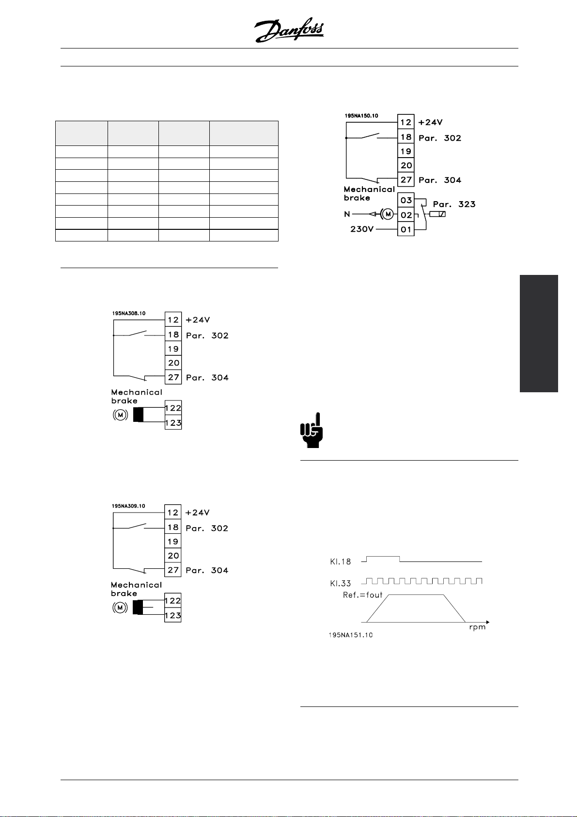
This table shows what the output frequency is:
Preset ref.,
msb
0 0 0 2.5
0 1 0 5
1 0 0 10
1 1 0 17.5
0 0 1 20
0 1 1 25
1 0 1 35
1 1 1 50
Preset ref.,
lsb
Selection of
Setup
■Connection of mechanical brake
Using terminal 122/123
Output
frequency[Hz]
Use of the relay for 230 V AC brake
Par. 302 Digital input = Start [7]
Par. 304 Digital input = Coasting stop inverted [2]
Par. 323 Relay output = Mechanical
brake control [25]
See also par. 138, 139, 140
Mechanical brake control [25] = ’0’ => Brake is closed.
Mechanical brake control [25] = ’1’ => The
brake is open.
See more detailed parameter settings under
Control of mechanical brake.
Installation
Par. 302 Digital
input = Start [7]
Par. 304 Digital input = Coasting stop inverted [2]
See also par. 138, 139, 140
Mechanical brake with accelerator winding
Par. 302 Digital input = Start [7]
Par. 304 Digital input = Coasting stop inverted [2]
See also par. 138, 139, 140
NB!:
Do not use the internal relay for DC brakes
or brake voltages > 250 V.
■Counter stop via terminal 33
The start signal (terminal 18) must be active, i.e. logical
’1’, until the output frequency is equal to the reference.
The start signal (terminal 18 = logical ’0’) must then be
removed before the counter value in parameter 344
has managed to stop the VLT frequency converter.
Par. 307 Digital input = Pulse input [30]
Par. 343 Precise stop function = Counter
stop with reset [1]
Par. 344 Counter value = 100000
MG.04.B7.02 - VLT is a registered Danfoss trademark
25
Page 26
VLT®FCD Series
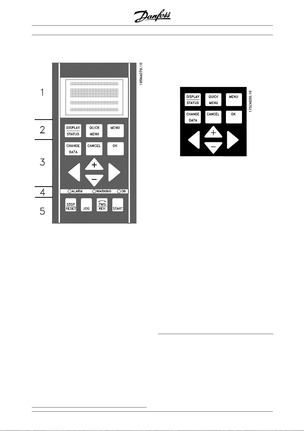
■The LCP 2 control unit, option
■Control keys for parameter Setup
The control keys are divided into functions, in
such a way that the keys between the display
and the indicator lamps are used for parameter
Setup, including selection of the display’sview
mode during normal operation.
[DISPLAY/STATUS] is used to select the display’s
view mode or to change back to Display mode
from either Quick Menu or Menu mode.
[QUICK MENU] provides access to the parameters
used in the Quick Menu. It is possible to switch
between Quick Menu and Menu mode.
The FCD 300 can be combined with an LCP control
unit (Local Control Panel - LCP 2) which makes up a
complete interface for operation and pro
the frequency converter. The LCP 2 control unit can
be attached up to three metres from the frequency
converter, e.g. on a front panel, usin
The control panel is divided into f
1. Display.
2. Keys used to change the display function.
3. Keys used to change the programme par
4. Indicator lamps.
5. Local control keys.
Alldataisdisplayedviaa4-linealphanumeric
display, which during normal ope
to continuously display 4 items of operating data
and 3 operating modes. During programming all
information needed for quick,
setup of the frequency converter will be displayed. As
asupplementtothedisplay,therearethreeindicator
lamps for voltage (ON), w
(ALARM). All frequency converter parameter Setups
can be changed immediately from the control panel,
unless this function h
[1] via parameter 018 Lock for data c hanges.
arning (WARNING) and alarm
as been programmed as Locked
ive functional groups:
ration will be able
effective parameter
gramming of
g an accessory kit.
ameters.
[MENU] givesaccesstoallparameters. Itispossible
to switch between Menu mode and Quick Menu.
[CHANGE DATA] is used to change a parameter that
has been selected either in Menu mode or Quick Menu.
[CANCEL] is used if a change to the selected
parameter is not to be implemented.
[OK] is used to confirm a change to a
selected parameter.
[+ / -] are used for selecting parameters and
for changing parameter values.
These keys are also used in Display mode to switch
between the readouts of operating variables.
[< >] are used for selecting parameter group and to
move the cursor when changing a numerical value.
26
MG.04.B7.02 - VLT is a registered Danfoss trademark
Page 27
VLT®FCD Series
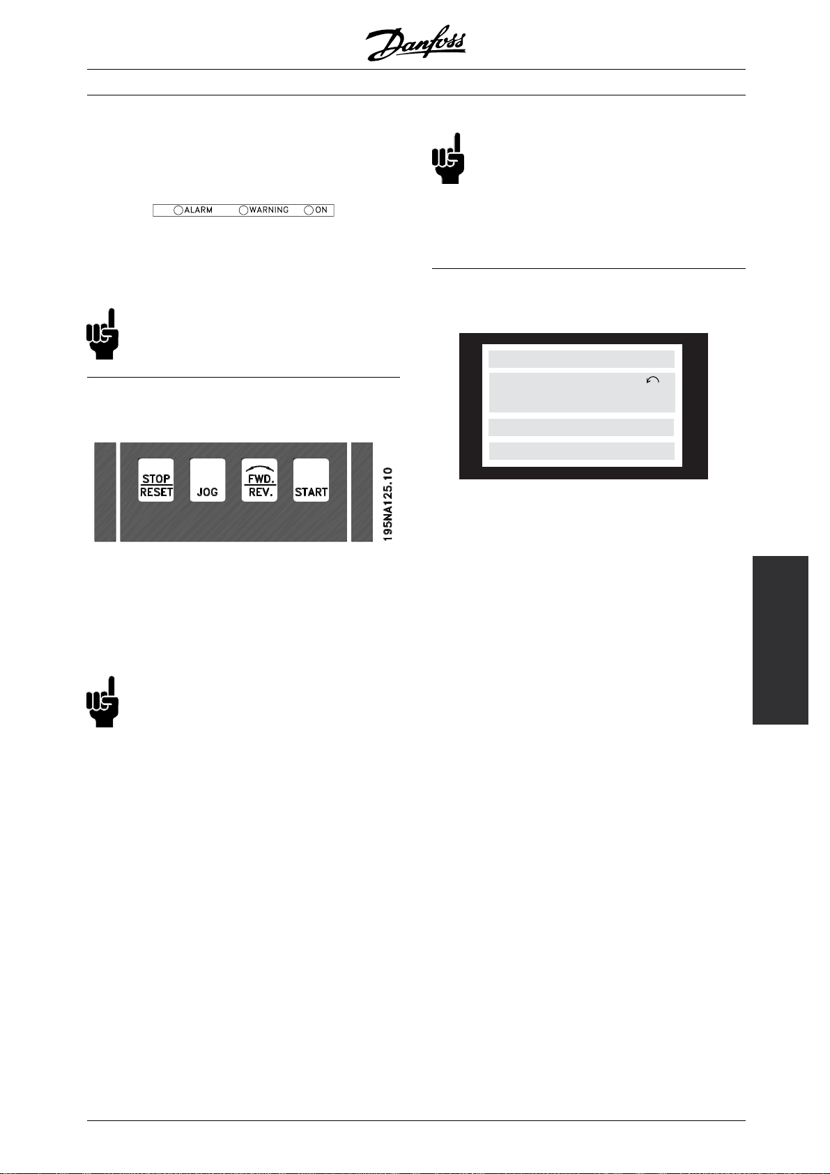
■Indicator lamps
At the bottom of the control panel are a red
alarm lamp, a yellow warning lamp and a
green voltage indicator lamp.
If certain threshold values are exceeded, the alarm
and/or warning lamp are activated, while a status
or alarm text is shown on the display.
NB!:
The voltage indicator lamp is activated when
voltage is connected to the frequency converter.
■Local control
[STOP/RESET] is used for stopping the motor
connected or for resetting the frequency converter
after a drop-out (trip). Can be set to active or
inactive via parameter 014 Local stop.
If stop is activated Display line 2 will flash.
NB!:
If an external stop function is not selected and
the [STOP/RESET] key is set to inactive, the
motor can only be stopped by disconnecting
the voltage to the motor or the frequency converter.
[JOG] changes the output frequency to a preset
frequency while the key is held down. Can be set to
active or inactive via parameter 015 Local jog.
NB!:
If the local control keys are set to inactive,
these will both become active when the
frequency converter is set to Loc al control
and Remote control via parameter 002 Local/remote
operation, with the exception of [FWD/REV], which
is only active in Local control.
■Display mode
VAR 1.1 VAR 1.2 VAR 1.3
SETUP
VAR 2
1
STATUS
In normal operation, up to 4 different display data
items can optionally be shown continuously: 1,1,
1,2, 1,3 and 2. The present operation status or
alarms and warnings that have been generated are
displayed in line 2 in the form of a number.
In the event of alarms this is displayed in lines
3and4withexplanatorytext.
A warning will appear flashing in line 2 with
explanatory text in line 1. The active Setup
will also appear on the display.
The arrow indicates the selected direction of rotation.
Here the frequency converter shows that it has
an active reversing signal. The body of the arrow
will disappear if a stop command is given, or if the
output frequency drops below 0.1 Hz.
The bottom line displays the frequency transformer’s
status. The scrollbar shows which operating values
can be displayed in lines 1 and 2 in Display mode.
Changes are made using the [+ / -] keys.
195NA113.10
300
Programming, FCD
[FWD / REV] changes the direction of rotation of
the motor, which is indicated by means of the arrow
on the display. Can be set to active or inactive via
parameter 016 Local reversing.The[FWD/REV]key
is only active when parameter 002 Local/remote
operation is set to Local control.
[START] is used to start the frequency converter. Is
always active, but cannot override a stop command.
MG.04.B7.02 - VLT is a registered Danfoss trademark
Switching between AUTO and HAND modes
By activating the [CHANGE DATA] key in [DISPLAY
MODE] the display will indicate the mode of
the frequency converter.
Switch mode by using [+/-] key [HAND...AUTO]
In [HAND] mode the reference can be changed
by [+] or [-] keys.
27
Page 28
VLT®FCD Series
Operating data Unit
Resulting reference [%]
Resulting reference [unit]
Feedback [unit]
Output frequency [Hz]
Output frequency x scaling [-]
Motor current [A]
Torque [%]
Power [kW]
Power [HP]
Motor voltage [V]
DC link voltage [V]
Thermal load motor [%]
Thermal load [%]
Hours run [hours]
Digital input [binary]
Pulse input 29 [Hz]
Pulse input 29 [Hz]
Pulse input 33 [Hz]
External reference [%]
Status word [hex]
Heatsink temperature [°C]
Alarm word [hex]
Control word [hex]
Warning word [hex]
Extended status word [hex]
Analogue input 53 [V]
Analogue input 60 [mA]
Three operating data items can be shown in the
first display line, and one operating variable can be
shown in the second display line. Is programmed via
parameters 009, 010, 011 and 012 Display readout .
■Display modes
The LCP control unit has different display
modes, which depend on the mode selected
for the frequency converter.
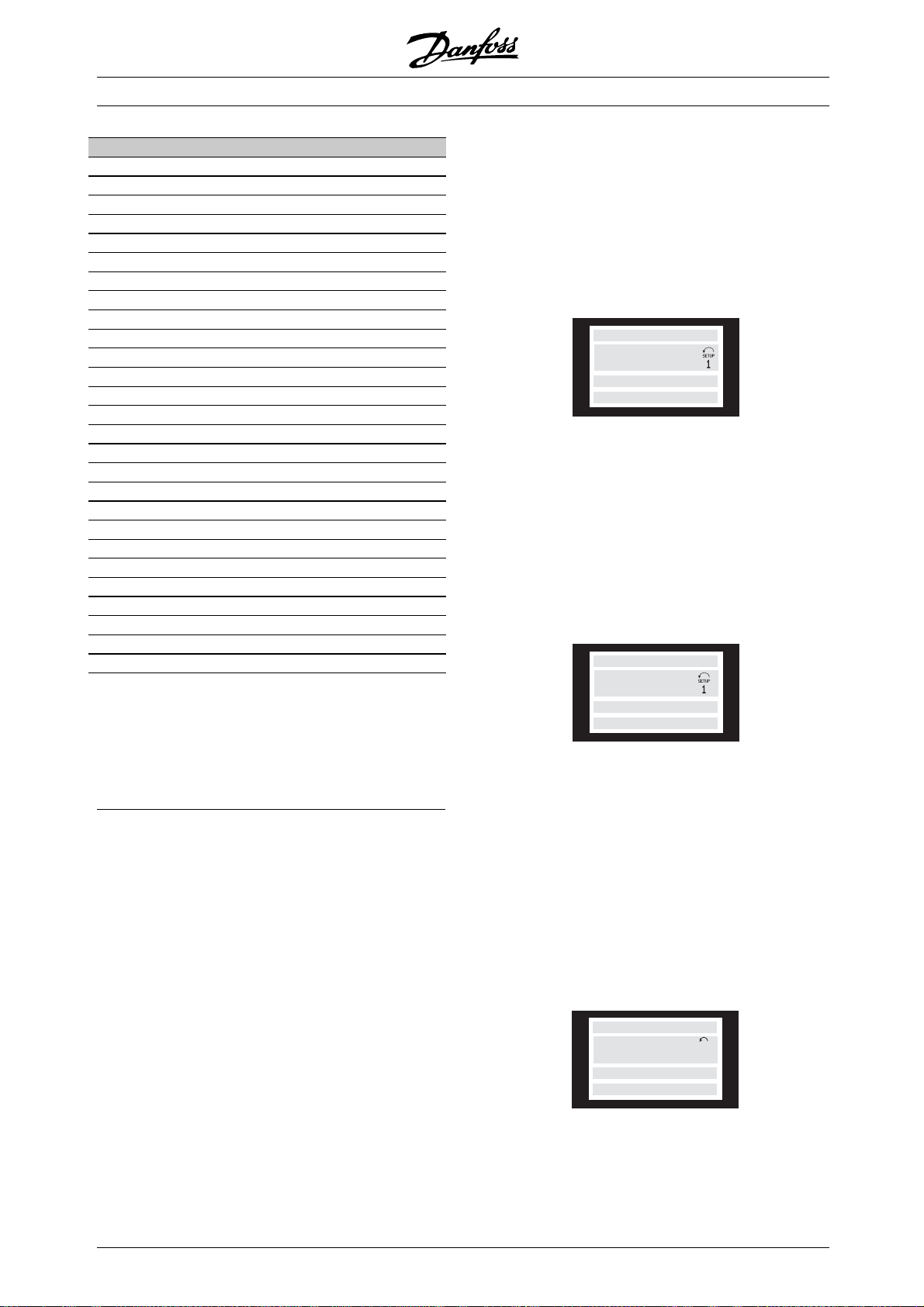
Display mode I:
This display mode is standard after startup
or initialisation.
FREQUENCY
50.0 Hz
MOTOR IS RUNNING
Line 2 shows the data value of an operating data item
with unit, and line 1 contains a text that explains line
2. In the example, Frequency has been selected as
readout via parameter 009 Large display readout.In
normal operation, another variable can be entered
immediately using the [+ / -] keys.
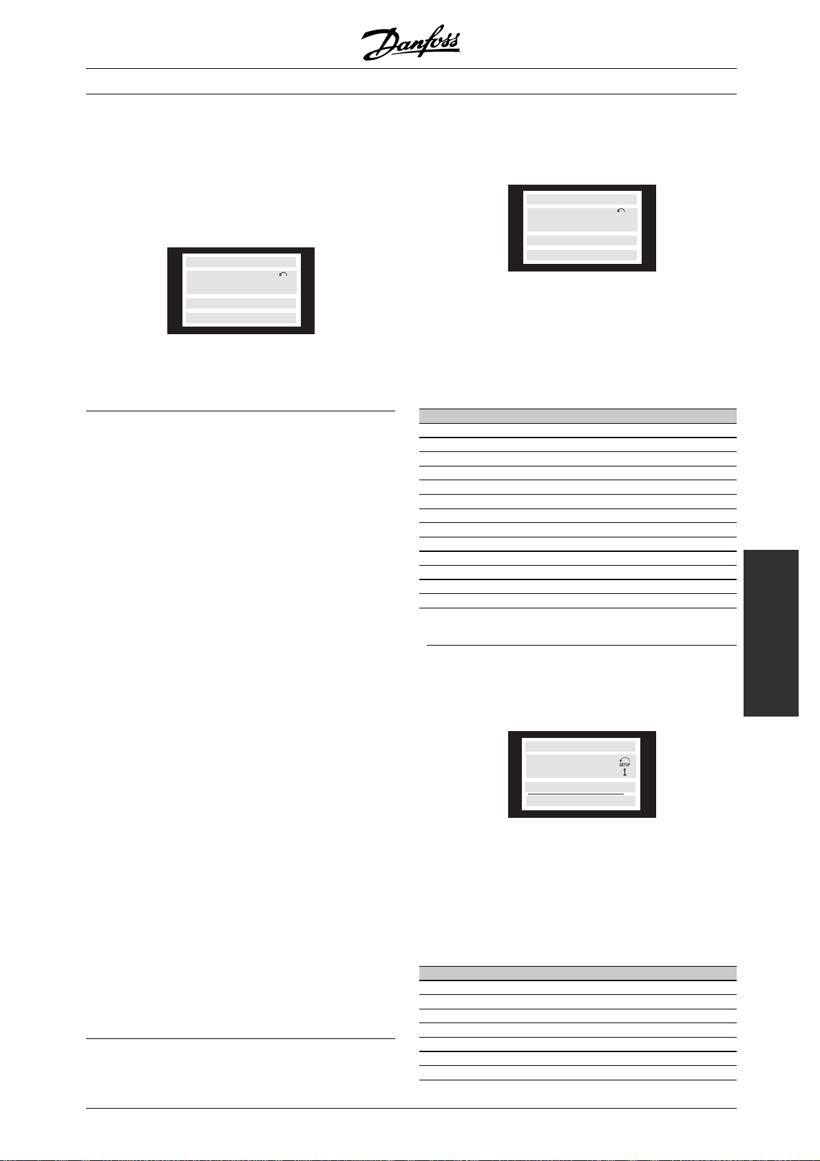
Display mode II:
Switch between Display modes I and II is performed
by briefly pressing the [DISPLAY / STATUS] key.
24.3% 30.2% 13.8A
50.0 Hz
MOTOR IS RUNNING
In this mode, all data values for four operating
data items with any pertaining units are shown,
see table. In the example, the following have been
selected: Frequency, Reference, Torque and Current
as readout in the first and second line.
28
Display mode III:
This display mode is called up as long as the [DISPLAY
/ STATUS] key is held down. When the key is released
it switches back to Display mode II, unless
the key is
held down for less than approx. 1 sec., in which case
the system always reverts to Display mode I.
REF% TORQUE CURR A
50.0 Hz
MOTOR IS RUNNING
SETUP
1
Here you can read out the parameter names and
units for operating data in the first and second lines.
Line 2 in the display remains unchanged.
MG.04.B7.02 - VLT is a registered Danfoss trademark
Page 29
DisplaymodeIV:
This display mode can be called up during operation
if a change has to be made in another Setup without
stopping the frequency converter. This function is
activated in parameter 005 Programming Setup.
24.3% 30.2% 13.8A
SETUP
50.0 Hz
MOTOR IS RUNNING
12
Here the programming Setup number 2 will flash
to the right of the active Setup.
■Parameter Setup
A frequency converter’s comprehensive work area can
be accessed via a large number of parameters, making
it possible to adapt its functionality for a specific
application. To provide a better overview of the many
parameters, there is a choice of two programming
modes - Menu mode and Quick Menu mode. The
former provides access to all parameters. The latter
takes the user through the parameters, which make
it possible to start operating the frequency converter
in most cases, in accordance with the Setup made.
Regardless of the mode of programming, a change
of a parameter will take effect and be visible both in
the Menu mode and in the Quick menu mode.
Structure for Quick menu m ode v Menu mode
In addition to having a name, each parameter is linked
up with a number which is the same regardless of
the programming mode. In Menu mode, paramet
will be split into groups, with the first digit (left)
of the parameter number indicating the group
number of the parameter in question.
VLT®FCD Series
■Quick m enu with LCP 2 control unit
Start Quick Setup by pressing the [QUICK MENU] key,
which will bring out the following display values:
QUICK MENU X OF Y
50.0 Hz
001 LANGUAGE
ENGLISH
At the bottom of the display, the parameter number
and name are given together with the status/value
of the first parameter under the Quick menu. The
first time the [QUICK MENU] key is pressed after
the unit has been switched on, the readouts always
start in pos. 1 - see table below.
Pos. Parameter no. Unit
1 001 Language
2 102 Motor power [kW]
3 103 Motor voltage [V]
4 104 Motor frequency [Hz]
5 105 Motor current [A]
6 106 Rated motor speed [rpm]
7 107 AMT
8 204 Minimum reference [Hz]
9 205 Maximum reference [Hz]
10 207 Ramp-up time [sec]
11 208 Ramp-down time [sec]
12 002 Local/remote operation
13 003 Local reference [Hz]
■Parameter selection
Menu mode is started by pressing the [MENU] key,
which produces the following readout on the display:
ers
FREQUENCY
50.0 Hz
0 KEYB.&DISPLAY
SETUP
1
300
Programming, FCD
• Using the [QUICK MENU] key, it is possibl
eto
get access to the most important parameters
of the frequency converter. After programming,
the frequency converter is in most
cases ready
for operation. Scroll through the Quick menu
using the [+ / -] keys and change the data values
by pressing [CHANGE DATA] + [OK
].
• The Menu mode allows choosing and changing
all parameters as required. However, some
parameters will be "shaded
off", depending on the
choice in parameter 100 Configuration .
MG.04.B7.02 - VLT is a registered Danfoss trademark
Line 3 on the display shows the parameter
group number and name.
In Menu mode, the parameters are divided
into groups. Selection of parameter group is
effected using the [< >] keys.
The following parameter groups will be accessible:
Group no. Parameter group
0 Operation & Display
1Load&Motor
2 References & Limits
3 Inputs & Outputs
4 Special functions
5 Serial communication
6 Technical functions
29
Page 30

VLT®FCD Series
When the required parameter group has been
selected, each parameter can be chosen by
means of the [+ / -] keys:
FREQUENCY
50.0 Hz
001 LANGUAGE
ENGLISH
The 3rd line of the display shows the parameter
number and name, while the status/value of the
selected parameter is shown in line 4.
Changing data
Regardless of whether a parameter has been
selected under the Quick menu or the Menu mode,
theprocedureforchangingdatawillbethesame.
Pressing the [CHANGE DATA] key gives access
to changing the selected parameter, following
which the underlining in line 4 will flash on the
display. The procedure for changing data depends
on whether the selected parameter represents a
numerical data value or a text value.
Changing a data value
If the selected parameter is a text value, the text
value is changed by means of the [+ / -] keys.
The chosen digit is indicated by the digit flashing. The
bottom display line shows the data value that will be
entered (saved) when signing off with [OK].
■ Manual initialisation
NB!:
Manual initialisation is n
the LCP 2 175N0131 control unit. It is,
however, possible to perform an initialisation
via par. 620 Operation mode:
The following parameters are not changed when
initialising via par. 620 Operation mode.
- par. 500 Address
- par. 501 Baud rate
- par. 600 Operat ing hours
- par. 601 Hours run
- par. 602 kWh counter
- par. 603 Number of power-ups
- par. 604 Number of overtemperatures
- par. 605 Number of overvoltages
- par. 615-617 Fault log
- par. 678 Configure Control Card
ot possible on
FREQUENCY
50.0 Hz
001 LANGUAGE
ENGLISH
The bottom display line will show the value that will be
entered (saved) when acknowledgment is given [OK].
Changeofnumericdatavalue
If the selected parameter is represented by a numerical
data value, a digit is first chosen using the [< >] keys.
FREQUENCY
50.0 Hz
130 START FREQUENCY
09.0 HZ
The selected digit can then be changed infinitely
variably using the [+ / -] keys:
FREQUENCY
50.0 Hz
130 START FREQUENCY
10.0 HZ
SETUP
1
SETUP
1
30
MG.04.B7.02 - VLT is a registered Danfoss trademark
Page 31

VLT®FCD Series
■Operation & Display
001 Language
(LANGUAGE)
Value:
✭English (ENGLISH)
German (DEUTSCH)
French (FRANCAIS)
Danish (DANSK)
Spanish (ESPANOL)
Italian (ITALIANO)
Function:
This parameter is used to choose the language
to be shown in the display whenever the LCP
control unit is connected.
Description of choice:
There is a choice of the languages shown.
The factory setting may vary.
002 Local/remote operation
(OPERATION SITE)
Value:
✭Remote operation (REMOTE)
Local operation (LOCAL)
Function:
There is a choice of two different modes of operation
of the frequency converter; Remote operation [0] or
Local operation [1]. See also parameter 013 Local
control if Local operation [1] is selected.
Description of choice:
If Remote operation [0] is selected, the frequency
converter is controlled via:
1. the control terminals or via serial communication.
2. the [START] key. This cannot, however, override
stop commands transmitted via the digital
inputs or via serial communication.
3. the [STOP/RESET] and [JOG] keys, on the
condition that these are active.
If Local operation [1], is selected, the frequency
converter is controlled via:
1. the [START] key. This cannot, however, override
stop commands via the digital inputs (see
parameter 013 Local control).
2. the [STOP/RESET] and [JOG] keys, on the
condition that these are active.
3. the [FWD/REV] key, on the condition that is has
been selected as active in parameter 016 Local
reversing, and that parameter 013 Local control
is set at Local control and open loop [1] or Local
control as parameter 100 [3]. Parameter 200
Output frequency range is set at Both directions.
4. parameter 003 Local reference where the reference
can be set using the [+] and [-] keys.
[0]
[1]
[2]
[3]
[4]
[5]
5. an external control command that can be
connected to the digital inputs (see parameter
013 Local control).
NB!:
The [JOG] and [FWD/REV] keys are located
on the LCP control unit.
003 Local reference
(LOCAL REFERENCE)
Value:
Par. 013 Local control must be set to [1] or [2]:
0-f
MAX
Par. 013 Local control must be set to [3] or [4].
Ref
MIN
[0]
[1]
Function:
In this parameter, the local reference can be set
manually. The unit of the local reference depends on the
configuration selected in parameter 100 Configuration.
Description of choice:
In order to protect the local reference, parameter
002 Local/remote operation must be set to
Local operation [1]. Local reference cannot be
set via serial communication.
■Setup configuration
There is a choice of four Setups (parameter Setups),
which can be programmed independently of one
another. The active Setup can be selected in
parameter 004 Act ive Setup. WhenanLCPcontrol
unit is connected, the active Setup number will be
appear in the display under "Setup". It is also possible
to preset the frequency converter to Multisetup,sothat
it is possible to shift Setups using the digital inputs
or serial communication. Setup shift can be used in
a plant in which, for example, one Setup is used for
daytime operation and another one at night time.
In parameter 006 Se tup copying it is possible to copy
from one Setup to another. Using parameter 007 LCP
copy all Setups can be transferred from one frequency
converter to another by moving the LCP control panel.
(par. 202)
-Ref
MAX
(par. 204-205)
✭ 50 Hz
✭ 0,0
300
Programming, FCD
= factory setting. () = display text [] = value for use in communication via serial communication port
✭
MG.04.B7.02 - VLT is a registered Danfoss trademark
31
Page 32

VLT®FCD Series
First all parameter values are copied to the LCP control
panel, which can then be moved to another frequency
converter. Here all parameter values can be copied
from the LCP control unit to the frequency converter.
■Setup shift
- Selection of Setup via terminals 29 and 33.
Par. 305 Digital input = Selection of Setup, lsb [31]
Par. 307 Digital input = Selection of Setup, msb [32]
Par. 004 Active setup = Multi Setup [5]
004 Active Setup
(ACTIVE SETUP)
Value:
Factory Setup (FACTORY SETUP)
✭Setup 1 (SETUP 1)
Setup 2 (SETUP 2)
Setup 3 (SETUP 3)
Setup 4 (SETUP 4)
Multi Setup (MULTI SETUP)
Function:
The active parameter Setup is selected here. All
parameters can be programmed in four individual
parameter Setups. Shifts between Setups can
be made in this parameter via a digital input
or via serial communication.
Description of choice:
Factory Setup [0] contains the factory-set parameter
values. Setup 1-4 [1]-[4] are four individual
Setups which can be selected as required. Multi
Setup [5] is used where remote-controlled shifts
between the four Setups via a digital input or via
serial communication is required.
005 Programming S etup
(EDIT SETUP)
Value:
Factory Setup (FACTORY SETUP)
Setup 1 (SETUP 1)
Setup 2 (SETUP 2)
= factory setting. () = display text [] = value for use in communication via serial communication port
✭
[0]
[1]
[2]
[3]
[4]
[5]
[0]
[1]
Setup 3 (SETUP 3)
Setup 4 (SETUP 4)
✭Active Setup (ACTIVE SETUP)
Function:
You can select which Setup you want to programme
during operation (applies both via the control
panel and the serial communication port). It is,
for example, possible to programme Setup 2
[2], while the active Setup is set to Setup 1 [1]
in parameter 004 Active Setup .
Description of choice:
Factory Setup [0] contains the factory-set data
and can be used as a source of data if the
other Setups are to be reset to a known status.
Setup 1-4 [1]-[4] are individual Setups that can
be programmed freely during operation. If Active
Setup [5] is selected, the programming Setup will
be equal to parameter 004 Active Setup.
NB!:
If data is modified or copied to the active
Setup, the modifications have an immediate
effect on the unit’soperation.
006 Setup copying
(SETUP COPY)
Value:
✭No copying (NO COPY)
Copy to Setup 1 from #
(COPY TO SETUP 1)
Copy to Setup 2 from #
(COPY TO SETUP 2)
Copy to Setup 3 from #
(COPY TO SETUP 3)
Copy to Setup 4 from #
(COPY TO SETUP 4)
Copy to all Setups from # (COPY TO ALL)
Function:
You can copy from the selected active Setup in
parameter 005 Programming setup to the selected
Setup or Setups in this parameter.
NB!:
Copying is only possible in Stop (motor stopped
in connection with a stop command).
Description of choice:
Copying begins when the required copying function
has been selected and the [OK]/[CHANGE DATA]
[2]
[3]
[4]
[5]
[0]
[1]
[2]
[3]
[4]
[5]
32
MG.04.B7.02 - VLT is a registered Danfoss trademark
Page 33

VLT®FCD Series
key has been pushed. The display indicates
when copying is in progress.
007 LCP copy
(LCP COPY)
Value:
✭No copying (NO COPY)
Upload all parameters (UPL. ALL PAR.)
Download all parameters (DWNL. ALL PAR.)
Download size-independent parameters
(DWNL.OUTPIND.PAR.)
Function:
Parameter 007 LCP copy is used if you want to use
the LCP 2 control panel’s integral copy function. The
function is used if you want to copy all parameter
setups from one frequency converter to another
by moving the LCP 2 control panel.
Description of choice:
Select Upload all parameters [1] if you want all
parameter values to be transferred to the control
panel. Select Download all parameters [2] if all
parameter values transferred are to be copied to the
frequency converter to which the control panel is
attached. Select Download size-independent par. [3]
if you only want to downloade the size-independent
parameters. This is used when downloading to a
frequency converter with a different rated power size
than that from which the parameter setup originates.
NB!:
Upload/download can only be performed
in stop mode. Download can o
performed to a frequency converter with
the same software version number, see parameter
626 Database identification no.
008 Display scaling of output frequency
(FREQUENCY SCALE)
Value:
0.01 - 100.00
Function:
In this parameter, the factor is selected by which the
output frequency is to be multiplied. The value is shown
in the display, provided parameters 009-012 Disp
readout have been set to Output frequency x scaling [5].
Description of choice:
Set the required scaling factor.
nly be
✭ 1.00
lay
[0]
[1]
[2]
[3]
009 Large d isplay readout
(DISPLAY LINE 2)
Value:
No readout (NONE)
Resulting reference [%]
(REFERENCE [%])
Resulting reference [unit]
(REFERENCE [UNIT])
Feedback [unit] (FEEDBACK [UNIT])
✭Frequency [Hz] (FREQUENCY [HZ])
Output frequency x scaling
(FREQUENCY X SCALE)
Motor current [A] (MOTOR CURRENT [A])
Torque [ %] ( TORQUE [%])
Power [kW] (POWER [KW])
Power [HP] (POWER [HP][US])
Motor voltage [V]
(MOTOR VOLTAGE [V])
DC link voltage [V]
(DC LINK VOLTAGE [V])
Thermal load motor [%]
(MOTOR THERMAL [%])
Thermal load [%]
(FC. THERMAL[%])
Running hours [Hours]
(RUNNING HOURS])
Digital input [Bin]
(DIGITAL INPUT[BIN])
Analog input 53 [V]
(ANALOG INPUT 53 [V])
Analog input 60 [mA]
(ANALOG INPUT 60 [MA])
Pulse reference [Hz]
(PULSE INPUT 33. [HZ])
External reference [%]
(EXTERNAL REF. [%])
Status word [Hex] (STATUS WORD [HEX])
Heatsink temperature [°C]
(HEATSINK TEMP [°C])
Alarm word [Hex] (ALARM WORD [HEX])
Control word [Hex] (CONTROL WORD [HEX])
Warning word [Hex]
(WARNING WORD [HEX])
Extended status word [Hex]
(EXT. STATUS [HEX])
Communication option card warning
(COMM OPT WARN [HEX])
Pulse count
(PULSE COUNTER)
Pulse input 29
(PULSE INPUT 29)
[0]
[1]
[2]
[3]
[4]
[5]
[6]
[7]
[8]
[9]
[11]
[12]
[13]
[14]
[15]
[16]
300
[17]
Programming, FCD
[19]
[20]
[21]
[22]
[25]
[26]
[27]
[28]
[29]
[30]
[31]
[32]
= factory setting. () = display text [] = value for use in communication via serial communication port
✭
MG.04.B7.02 - VLT is a registered Danfoss trademark
33
Page 34

VLT®FCD Series
Function:
In this parameter you can select the data value that
you wish to display in the L C P c o n t r o l u nit display
line 2 when the frequency converter is switched on.
The display will also be included in the scrollbar
in display mode. In parameters 010-012 Display
readout you can select a further three data values,
whicharedisplayedindisplayline1.
Description of choice:
No readout can only be selected in parameters
010-012 Small display readout.
Resulting reference [%] gives, as a percentage,
the resulting reference in the range from Minimum
reference, Ref
to Maximum reference, Ref
MIN
MAX
.
Reference [unit] gives the resulting reference with unit
Hz in Open loop.InClosed loop the reference unit
is selected in parameter 416 Process units.
Feedback [unit] gives the resulting signal value
using the unit/scaling selected in parameter 414
Minimum feedback, FB
FB
and 416 Process units.
HIGH
, 415 Maximum feedback,
LOW
Frequency [Hz] gives the output frequency of
the frequency converter.
Output frequency x scaling [-] equals the present
output frequency f
multiplied by the factor set in
M
parameter 008 Display scaling of output frequency .
Running hours [Hours] gives the number of hours that
the motor has tun since the last reset in parameter
619 Reset of running hours counter.
Digital input [Binar y code] gives the signal status
from the 5 digital inputs (18, 19, 27, 29 and 33).
Terminal 18 corresponds to the bit on the extreme
left. ‘0’ = no signal, ‘1’ = signal connected.
Analog input 53 [V] gives the voltage value
of terminal 53.
Analog input 60 [mA] gives the present
value of terminal 60.
Pulse input 33[Hz] gives the frequency in Hz
connected to terminal 33.
External reference [%] gives the sum of
external references as a percentage (sum of
analogue/pulse/serial communication) in the
range from Minimum reference, Ref
Maximum reference, Ref
MAX
.
MIN
to
Status word [Hex] gives one or several status
conditions in a Hex code. See Serial communic ation
in the Design Guide for further information.
Heatsink temp.[°C] gives the present heatsink
temperature of the frequency converter. The
cut-out limit is 90-100 °C, while cutting back
in occurs at 70 ± 5 °C.
Motor current [A] gives the phase current of the
motor measured as an effective value.
Torque [%] denotes the motor’s present load in
relation to the motor’s rated torque.
Power [kW] gives the present power that
the
motor is absorbing in kW.
Power [HP] gives the present power that the
motor is absorbing in HP.
Motor voltage[V] gives the voltage supplied to the motor.
DC link voltage [V] gives the intermediate circuit
voltage of the frequency conve
Thermal load motor [%] gives th
rter.
e calculated/estimated
load on the motor. 100 % is the cut-out limit.
Thermal load [%] gives the calculated/estimated
thermal load on the frequency converter. 100
% is the cut-out limit.
Alarm word [Hex] gives one or several alarms
in hex code. See Serial communication in the
Design Guide for further information.
Control word [Hex] gives the control word for the
frequency converter. See Serial communication in
the Design Guide for further information.
Warning word [Hex] gives one or several warnings
in hex code. See Serial communication in the
Design Guide for further information.
Extended status word [H ex] gives one or several status
modes in Hex code. See Serial communication in
the Design Guide for further information.
Communication option card warning [Hex] gives a
warning word if there is a fault in the communication
bus. Only active if communication options are installed.
If there are no communication options 0
Hex is displayed.
= factory setting. () = display text [] = value for use in communication via serial communication port
✭
34
MG.04.B7.02 - VLT is a registered Danfoss trademark
Page 35

VLT®FCD Series
Pulse input 29[Hz] gives the frequency in Hz
connected to terminal 29.
Pulse count gives the number of pulses that
the unit has registered.
010 Small display line 1.1
(DISPLAY LIN E 1.1)
Value:
See par. 009 Large display readout
✭ Analog input 53 [V] [17]
Function:
In this parameter, the first of three data values
can be selected that is to be displayed in the
LCP control unit display, line 1, position 1. This
is a useful function, e.g. when setting the PID
regulator, as it gives a view of process reactions to
reference changes. The display readout is activated
by pushing the [DISPLAY STATUS] key.
Description of choice:
See parameter 009 Large display readout.
011 Small display readout 1.2
(DISPLAY LIN E 1.2)
Value:
See parameter 009 Large display readout
✭ Motor current [A][6]
Function:
See the functional description given under parameter
010 Small display readout.
Description of choice:
See parameter 009 Large display readout.
Description of choice:
See parameter 009 Large display readout.
013 Local control
(LOC CTRL/CONFIG.)
Value:
Local not active (DISABLE)
Local control and open loop without slip
compensation
(LOC CTRL/OPEN LOOP)
Remote-operated control and open loop
without slip compensation
(LOC+DIG CTRL)
Local control as parameter 100
(LOC CTRL/AS P100)
✭Remote-operated control as parameter 100
(LOC+DIG CTRL/AS P100)
Function:
This is where the required function is selected if,
in parameter 002 Local/remote operation, Local
operation [1] has been chosen.
Description of choice:
If Loc al not active [0] is selected, it is not possible to
set a reference via parameter 003 Local reference.
In order to enable a shift to Local not active
[0], parameter 002 Local/remote operation must
be set to Remote operation [0].
Local control and open loop [1] is used if the motor
speed is to be set via parameter 003 Local reference.
When this choice is made, parameter 100 Configuration
automatically shifts to Speed regulation, open loop [0].
Remote-operated control and open loop [2] functions
in the same way as Local control and open loop
[1]; however, the frequency converter can also
be controlled via the digital inputs.
[0]
[1]
[2]
[3]
[4]
300
Programming, FCD
For selections [1-2] control is shifted to open
012 Small display readout 1.3
(DISPLAY LIN E 1.3)
Value:
See parameter 009 Large display readout
✭ Feedback [unit] [3]
Function:
See the functional description given under parameter
010 Small display readout.
= factory setting. () = display text [] = value for use in communication via serial communication port
✭
MG.04.B7.02 - VLT is a registered Danfoss trademark
loop, no slip compensation.
Local c ontrol as parameter 100 [3] is used when
the motor speed is to be set via parameter
003 Local reference,butw
Configuration automatically shifting to Speed
regulation, open loop [0].
Remote-operated control as parameter 100 [4]
works the same way as Local control as parameter
100 [3]; however, the frequency converter can also
be controlled via the digital inputs.
ithout parameter 100
35
Page 36

VLT®FCD Series
Shifting from Remote operation to Local operation
in parameter 002 Local/remote operation,whilethis
parameter has been set to Remote-operated control
and open loop [1]: The present motor frequency and
direction of rotation will be maintained. If the present
direction of rotation does not respond to the reversing
signal (negative reference), the reference will be set to 0.
Shifting from Local operation to Remote operation
in parameter 002 Local/remote control,while
this parameter has been set to Remote-operated
control and open loop [1]: The configuration
selected in parameter 100 Configuration will be
active. The shift will be smooth.
Shifting from Remote control to Local control in
parameter 002 Local/remote operation,whilethis
parameter has been set to Remote-operated control
as parameter 100 [4]: the present reference will
be maintained. If the reference signal is negative,
thelocalreferencewillbesetto0.
Shifting from Local operation to Remote operation
in parameter 002 Local/remote operation, while
this parameter has been set to Remote operation:
The local reference will be replaced by the
remote-operated reference signal.
Function:
In this parameter, the jog function on the LCP
control panel can be engaged/disengaged.
Description of choice:
If Not active [0] is selected in this parameter,
the [JOG]-key will be inactive.
016 Local reversing
(LOCAL REVERSING)
Value:
✭Not active (DISABLE)
Active (ENABLE)
Function:
In this parameter you can select/deselect the reversing
function on the LCP control panel. The key can only
be used if parameter 002 Local/remote operation
is set to Local operation [1] and parameter 013
Localcontrol to Local control, open loop [1] or
Local control as parameter 100 [3].
Description of choice:
If Disable [0] is selected in this parameter, the
[FWD/REV] key will be disabled. See also parameter
200 Output frequency range.
[0]
[1]
014 Local stop
(LOCAL STOP)
Value:
Not active (DISABLE)
✭Active (ENABLE)
Function:
In this parameter, the local [STOP]-key can be
engaged or disengaged on the control panel
and on the LCP control panel.
Description of choice:
If Not active [0] is selected in this parame
the [STOP]-key will be inactive.
NB!:
If Not active [0] is selected, the motor cannot
be stopped by means of the [STOP]-key.
015 Local jog
(LOCAL JOGGING)
Value:
✭Not active (DISABLE)
Active (ENABLE)
ter,
[0]
[1]
[0]
[1]
017 Local reset of trip
(LOCAL RESET)
Value:
Not active (DISABLE)
✭Active (ENABLE)
Function:
In this parameter, the reset function on the control
panel can be engaged/disengaged.
Description of choice:
If Not active [0] is selected in this parameter,
the reset function will be inactive.
NB!:
Select Not active [0], only if an external reset
signal has been connected via the digital inputs.
018 Lock for data changes
(DATA CHANGE LOCK)
Value:
✭Not locked (NOT LOCKED)
Locked (LOCKED)
[0]
[1]
[0]
[1]
✭
= factory setting. () = display text [] = value for use in communication via serial communication port
36
MG.04.B7.02 - VLT is a registered Danfoss trademark
Page 37

VLT®FCD Series
Function:
In this parameter, it is possible to ’lock’ the controls
to disable data changes via the control keys.
Description of choice:
If Locked [1] is selected, data changes in the
parameters cannot be made; however, it will
still be possible to make data changes via serial
communication. Parameter 009-012 Display readout
can be changed via the control panel.
019 Operating m ode at power-up, local
operation
(POWER UP ACTION)
Value:
Auto restart, use saved reference
(AUTO RESTART)
✭Forced stop, use saved reference
(LOCAL=STOP)
Forced stop, set ref. to 0
(LOCAL=STOP, REF=0)
[0]
[1]
[2]
020 Lock for Hand mode
(LOCK HAND MODE)
Value:
✭Not active (DISABLE)
Active (ENABLE)
Function:
In this parameter you can select whether it should
be possible or not to switch between Auto- and
Hand mode. In Auto mode the frequency converter is
controlled by external signals whereas the frequency
converter in Hand mode is controlled via a local
reference directly from the control unit.
Description of choice:
If Not active [0] is selected in this parameter, the Hand
mode function will be inactive. This blocking can be
activated as desired. If Active [1] is selected you can
switch between Auto- and Hand mode.
NB!:
ThisparameterisonlyvalidforLCP2.
[0]
[1]
Function:
Setting of the required operating mode when the
mains voltage is engaged. This function can only
be active if Local operation [1] has been selected
in parameter 002 Local/remote operation.
Description of choice:
Auto restart, use saved ref. [0] is selected if the
frequency converter is to start using the local reference
(set in parameter 003 Local reference)andthe
start/stop state given via the control keys immediately
prior to the mains voltage being cut out.
Forced stop, use saved ref. [1] is selected if the
frequency converter is to remain stopped when the
mains voltage is engaged, until the [START]-key
is activated. After a start command the motor
speed is ramped up to the saved reference in
parameter 003 Local reference.
Forced stop, set ref. to 0 [2] is selected if the
frequency converter is to remain stopped when
the mains voltage is cut back in. Parameter 003
Local reference is to be zeroed.
024 Userdefined Quick Menu
(USER QUICKMENU)
Value:
✭Not active (DISABLE)
Active (ENABLE)
Function:
In this parameter you can select the standard
setup of the Quick menu key on the control
panel and the LCP 2 control panel.
Using this function, in parameter 025 Quick Menu
setup the user can select up to 20 parameters
for the Quick Menu key.
Description of choice:
If not active [0] is selected, the standard setup
of the Quick Menu key is active.
If Active [1] is selected, the user-defined
Quick Menu is active.
[0]
[1]
300
Programming, FCD
NB!:
In remote operation (parameter 002
Local/remote operation) the start/stop state
at the time of mains connection will depend
on the external control signals. If Pulse start [8] is
selected in parameter 302 Digital input,themotor
will remain stopped after mains connection.
✭ = factory setting. () = display text [] = value for use in communication via serial communication port
MG.04.B7.02 - VLT is a registered Danfoss trademark
37
Page 38

VLT®FCD Series
025 Quick Menu setup
(QUICK MENU SETUP)
Value:
[Index 1 - 20] Value: 0 - 999
Function:
In this parameter you define which parameters are
required in the Quick Menu when parameter 024
User-defined Quick Menu is se t to Active [1]´.
Up to 20 parameters can be selected for the
user-defined Quick Menu.
NB!:
Please note that this parameter can only be set
using an LCP 2 control panel. See Order form.
Description of choice:
The Quick Menu is set up as follows:
1. Select parameter 025 Quick Menu setup
and press [CHANGE DATA].
2. Index 1 indicates the first parameter in Quick
Menu. You can scroll between the index numbers
using the [+ / -] keys. Select Index 1.
3. Using [< >] you can scroll between the
three figures. Press the [<] key once ad
the last number in the parameter number
can be selected using the [+ / -] keys.
Set Index 1 to 100 for parameter 100 Configuration.
4. Press [OK] when Index 1 has been set to 100.
5. Repeat steps 2 - 4 until all parameters required
have been set to the Quick Menu key.
6. Press [OK] to complete the Quick Menu setup.
If parameter 100 Configuration is selected at
Index 1, Quick Menu will start with this parameter
every time Quick Menu is activated.
✭ 000
As dig.outp. par. 341 (AD DIG. OUT. / P341)
As mech.brake output
(AS MECH. BRAKE OUTPUT)
Function:
This parameter enables the user to visualize different
situations using the Status LED.
Description of choice:
Select the function to be visualized.
[9]
[10]
Please note that parameter 024 User-defined Quick
Menu and parameter 025 Quick Menu setup are
reset to the factory setting during initialisation.
026 LED Status
(LED STATUS)
Value:
✭Overload (OVERLOAD)
Therm. warn/alarm 36 (OVERTEMP)
Thermistor/ETR (THERMAL MOTOR)
Digital input 18 (DIGITAL INPUT 18)
Digital input 19 (DIGITAL INPUT 19)
Digital input 27 (DIGITAL INPUT 27)
Digital input 29 (DIGITAL INPUT 29)
Digital input 33 (DIGITAL INPUT 33)
As relay par. 323 (AS RELAY / P323)
✭ = factory setting. () = display text [] = value for use in communication via serial communication port
38
[0]
[1]
[2]
[3]
[4]
[5]
[6]
[7]
[8]
MG.04.B7.02 - VLT is a registered Danfoss trademark
Page 39

VLT®FCD Series
■Load and Motor
■Configuration
Selection of configuration and torque characteristics
has an effect on which parameters can be seen in the
display. If Open loop [0] is selected, all parameters
relating to PID regulation will be filtered out. This
means that the user only sees the parameters that
are relevant for a given application.
100 Configuration
(CONFIGURATION)
Value:
✭Speed control, open loop
(SPEED OPEN LOOP)
Speed control, closed loop
(SPEED CLOSED LOOP)
Process control, closed loop
(PROCESS CLOSED LOOP)
Function:
This parameter is used to select the configuration
to which the frequency converter is to be adapted.
This makes adaptation to a given application
simple, since the parameters not used in a given
configuration are hidden (not active).
[0]
[1]
[3]
101 Torque characteristic
(TORQUE CHARACT)
Value:
✭Constant torque
(CONSTANT TORQUE)
Variable torque low
(TORQUE: LOW)
Variable torque medium
(TORQUE: MED)
Variable torque high
(TORQUE: HIGH)
Variable torque low with CT start
(VT LOW CT START)
Variable torque medium with CT start
(VT MED CT START)
Variable torque high with CT start
(VTHIGHCTSTART)
Special motor mode
(SPECIAL MOTOR MODE)
CT = Constant torque
Function:
This parameter enables a choice of principle
for adaptation of the U/f ratio of the frequency
converter to the torque characteristic of the
load. See par. 135 U/f ratio.
[1]
[2]
[3]
[4]
[5]
[6]
[7]
[8]
Description of choice:
If Speed control, open loop [0] is selected, normal
speed control is obtained (without feedback
signal) with automatic load and slip compensation
to ensure a constant speed at varying loads.
Compensations are active, but may be disabled in
parameter 134 Load compensation and parameter
136 Slip compensation as required.
If Speed control, closed loop [1] is selected, better
speed accuracy is obtained. A feedback signal must
be added, and the PID regulator must be set in
parameter group 400 Special functions.
If Process control, closed loop [3] is selected, the
internal process regulator is activated to enabl
control of a process in relation to a given process
signal. The process signal can be set to the relevant
process unit or as a percentage. A feedback sign
must be added from the process and the process
regulator must be set in parameter group 400 Special
functions. Process closed loop is not ac
DeviceNet card is mounted and Instance 20/70 or
21/71 is chosen in parameter 904 Instance types.
eprecise
al
tive if a
Description of choice:
If Constant torque [1] is selected, a load-dependent U/f
characteristic is obtained, in which output voltage and
output frequency are increased at increasing loads in
order to maintain constant magnetization of the motor.
Select Variable torque low [2], Variable torque
medium [3] or Variable torque high [4], if the load
is square (centrifugal pumps, fans).
Variable torque - low with CT start [5], -mediumwith
CT start [6] or high with CT start [7], are selected if
you need a greater breakaway torque than can be
achieved with the three first characteristics.
NB!:
Load and slip compensation are not
active if variable torque or special motor
mode have been selected.
300
Programming, FCD
= factory setting. () = display text [] = value for use in communication via serial communication port
✭
MG.04.B7.02 - VLT is a registered Danfoss trademark
39
Page 40

VLT®FCD Series
Description of choice:
Select a value that corresponds to the nameplate
data on the motor, regardless of the frequency
converter’s mains voltage.
Select Special motor mode [8], if a special U/f
setting is needed that is to be adapted to the
present motor. The break points are set in
parameters 423-428 Voltage/frequency .
NB!:
Pleasenotethatifavaluesetinthenameplate
parameters 102-106 is changed, there will
be an automatic change of parameter 108
Stator resistance and 109 Stator reactance.
102 Motor power P
M,N
(MOTOR POWER)
Value:
0.18 - 4 kW
✭ Depends on unit
Function:
Here you must set a power value [kW] P
M,N
,
corresponding to the motor’s rated power. The
factory sets a rated power value [kW] P
M,N
,
that depends on the type of unit.
Description of choice:
Set a value that matches the nameplate data on the
motor. Settings between two sizes below and one
size over the factory setting are possible.
103 Motor voltage U
M,N
(MOTOR VOLTAGE)
Value:
50 - 999 V
✭ 400 V
Function:
This is where to set the rated motor voltage
U
foreitherstarYordelta .
M,N
104 Motor frequency f
M,N
(MOTOR FREQUENCY)
Value:
24-1000 Hz
✭ 50 Hz
Function:
This is where to select the rated motor frequency f
M,N
Description of choice:
Select a value that corresponds to the nameplate
data on the motor.
105 Motor current I
M,N
(MOTOR CURRENT)
Value:
0,01 - I
MAX
✭ Depends on choice of motor
Function:
The nominal, rated current of the motor I
M,N
forms
part of the frequency converter calculation of features
such as torque and motor thermal protection.
Description of choice:
Setavaluethatcorrespondstothenameplate
data on the motor. Set the motor current
taking into account whether the motor is
I
M,N
star-connected Y or delta-connected
.
106 Rated motor speed
(MOTOR NOM. SPEED)
Value:
100 - f
✭ Depends on parameter 104 Motor frequency, f
x 60 (max. 60000 rpm)
M,N
M,N
Function:
This is where to set the value that corresponds
to the rated motor speed n
that can be
M,N
seen from the nameplate data.
Description of choice:
Select a value that corresponds to the nameplate
data on the motor.
.
= factory setting. () = display text [] = value for use in communication via serial communication port
✭
40
MG.04.B7.02 - VLT is a registered Danfoss trademark
Page 41

VLT®FCD Series
NB!:
The max. value equals f
M,N
x 60. f
set in parameter 104 Motor frequency, f
M,N
to be
M,N
.
107 Automatic motor tuning, AMT
(AUTO MOTOR TUN.)
Value:
✭Optimisation off (AMT OFF)
Optimisation on (AMT START)
Function:
Automatic motor tuning is an algorithm that measures
stator resistance R
without the motor axle turning.
S
This means that the motor is not delivering any torque.
AMT can be used with benefit when initialising units
where the user wishes to optimise adjustment of
the frequency converter to the motor being used.
This is used in particular when the factory setting
does not sufficiently cover the motor.
For the best possible tuning of the frequency converter
it is recommended that AMT is performed on a
cold motor. It should be noted that repeated AMT
runs can cause heating of the motor, resulting
in an increase in the stator resistance R
.Asa
S
rule, however, this is not critical.
AMT is performed as follows:
S
tart AMT:
1. Give a STOP signal.
2. Parameter 107 Automatic motor tuning is se t
at value [2] Optimisation on.
3. A START signal is given and parameter 107
Automatic motor tuning is r e set to [0 ] when
AMT has been completed.
In factory setting START requires terminals 18 and
27 to be connected to terminal 12.
omplete AMT:
C
AMT is completed by giving a RESET signal.
Parameter 108 Stator resistance, Rs is updated
with the optimised value.
nterrupting AMT:
I
AMT can be interrupted during the optimisation
procedure by giving a STOP signal.
When using the AMT function the following
points should be observed:
- For AMT to be able to define the motor paramete
as well as possible, the correct type plate data for
[0]
[2]
the motor connected to the frequency converter
must be keyed into parameters 102 to 106.
- Alarms will appear in the display if faults arise
during tuning of the motor.
- As a rule the AMT function will be able to measure
values for motors that are 1-2 times larger or
the R
S
smaller than the frequency converter’snominalsize.
- If you wish to interrupt automatic motor tuning,
press the [STOP/RESET] key.
NB!:
AMT may not be performed on motors
connected in parallel, nor may setup changes
be made while AMT is running.
Description of choice:
Select Optimisation on [2] if you want the frequency
converter to perform automatic motor tuning.
108 Stator res istance R
S
(STATOR RESISTAN)
Value:
0.000 - X.XXX
✭ Depends on choice of motor
Function:
After setting of parameters 102-106 Nameplate data,
a number of adjustments of various parameters is
300
carried out automatically, including stator resistance
. A manually entered RSmust apply to a cold
R
S
motor. The shaft performance can be improved by
fine-tuning R
and XS, see procedure below.
S
Programming, FCD
NB!:
Parameters 108 Stator resistance R
Stator reactance X
are normally not to be
S
and 109
S
changed if nameplate data has been set.
Description of choice:
can be set as follows:
R
S
1. Use the factory settings of R
which the
S
frequency converter itself chooses on the basis
of the motor nameplate data.
2. The value is stated by the motor supplier.
3. The value is obtained through manual
measurements: R
theresistanceR
terminals. R
is set automatically when AMT has
4. R
rs
S
been completed. See parameter 107
can be calculated by measuring
S
PHASE-PHASE
=0.5xR
S
between two phase
PHASE-PHASE
.
Auto motor adaption.
✭ = factory setting. () = display text [] = value for use in communication via serial communication port
MG.04.B7.02 - VLT is a registered Danfoss trademark
41
Page 42

VLT®FCD Series
109 Stator reactance X
S
(STATOR REACTANCE)
Value:
0.00 - X,XX
✭ Depends on choice of motor
Function:
After setting of parameters 102-106 Nameplate data,
a number of adjustments of various parameters
are made automatically, including stator reactance
. The shaft performance can be improved by
X
S
fine-tuning R
and XS, see procedure below.
S
Description of choice:
can be set as follows:
X
S
1. The value is stated by the motor supplier.
2. The value is obtained through manual
measurements X
is obtained by connecting a
S
motor to mains and measuring the phase-phase
voltage U
and the idle current .
M
XL: See parameter 142.
3. Use the factory settings of X
which the
S
frequency converter itself chooses on the basis
of the motor nameplate data.
117 Resonance dampening
(RESONANCE DAMP.)
Value:
0 - 100 %
✭ 0%
Function:
Reduces the output voltage when running at low
load for avoiding resonance phenomena.
Description of choice:
If 0 is selected, there will be no reduction. If 100 % is
selected, the voltage is reduced to 50% at no load.
119 High start torque
(HIGH START TORQ.)
Value:
0.0 - 0.5 sec.
✭ 0.0 sec.
Function:
To ensure a high start torque approx. 1.8 x I
INV.
can be
permitted for max. 0.5 sec. The current is, however,
limited by the frequency converter’s(inverter’s) safety
limit. 0 sec. corresponds to no high start torque.
Description of choice:
Set the necessary time for which a high
start torque is required.
120 Start delay
(START DELAY)
Value:
0.0 - 10.0 sec.
✭ 0.0 sec.
Function:
This parameter enables a delay of the start-up time
after the conditions for start have been fulfilled.
When the time has passed, the output frequency
will start by ramping up to the reference.
Description of choice:
Set the necessary time before commencing
to accelerate.
121 Start function
(START FUNCTION)
Value:
DC hold during start delay time
(DC HOLD/DELAY TIME)
DC brake during start delay time
(DC BRAKE/DELAY TIME)
✭Coasting during start delay time
(COAST/DELAY TIME)
Start frequency/voltage clockwise
(CLOCKWISE OPERATION)
Start frequency/voltage in reference direction
(VERTICAL OPERATION)
Function:
This is where to choose the required mode during the
start delay time (parameter 120 Start delay time).
Description of choice:
Select DC hold during start delay time [0] to energize
the motor with a DC hold voltage during the start delay
time. Set voltage in parameter 137 DC hold voltage.
Choose DC brake during start delay time [1] to energize
the motor with a DC brake voltage during the start delay
time. Set voltage in parameter 132 DC brake voltage.
Choose Coasting during start delay time [2] and the
motor will not be controlled by the frequency converter
during the start delay time (inverter turned off).
[0]
[1]
[2]
[3]
[4]
= factory setting. () = display text [] = value for use in communication via serial communication port
✭
42
MG.04.B7.02 - VLT is a registered Danfoss trademark
Page 43

VLT®FCD Series
Choose Start frequency/voltage clockwise [3] to
obtain the function described in parameter 130
Start frequency and 131 Voltage at start during start
delay time. Regardless of the value assumed by
the reference signal, the output frequency equals
the setting in parameter 130 Start frequency and
the output voltage will correspond to the setting
in parameter 131 Voltage at start .
This functionality is typically used in hoist applications.
It is used in particular in applications in which a cone
anchor motor is applied, where the direction of rotation
is to start clockwise followed by the reference direction.
Select Start frequency/voltage in reference direction
[4] to obtain the function described in parameter
130 Start frequency and 131 Voltage at start
during the start delay time.
The direction of rotation of the motor will always
follow in the reference direction. If the reference signal
equals zero, the output frequency will equal 0 Hz,
while the output voltage will correspond to the setting
in parameter 131 Voltageatstart. If the reference
signal is different from zero, the output frequency will
equal parameter 130 Start frequency and the output
voltage will equal parameter 131 Voltage at start.This
functionality is used typically for hoist applications with
counterweight. It is used in particular for applications
in which a cone anchor motor is applied. The cone
anchor motor can break away using parameter 130
Start frequency and parameter 131 Voltage at start.
122 Function at stop
(FUNCTION AT STOP)
Value:
✭Coasting (COAST)
DC hold (DC HOLD)
Function:
This is where to choose the function of the frequency
converter after the output frequency has become
lower than the value in parameter 123 The min.
frequency for activation of function at stop or after
a stop command and when the output frequency
has been ramped down to 0 Hz.
[0]
[1]
123 Min. frequency for activation of
function at stop
(MIN.F.FUNC.STOP)
Value:
0,1 - 10 Hz
Function:
In this parameter, the output frequency is set at
which the function selected in parameter 122
Function at stop is to be activated.
Description of choice:
Set the required output frequency.
NB!:
If parameter 123 is set higher than parameter
130, then the start delay function (parameter
120 and 121) will be skipped.
NB!:
If parameter 123 is set too high, and DC
hold has been chosen in parameter 122,
the output frequency will jump to the value
in parameter 123 without ramping up. This may
cause an overcurrent warning / alarm.
■DC Braking
During DC braking DC voltage is supplied to the
motor, and this will cause the shaft to be brought to
a standstill. In parameter 132 DC brake voltage DC
brake voltage can be preset from 0-100%. Max. DC
brake voltage depends on the motor data selected.
In parameter 126 DC braking time DC braking time
is determined and in parameter 127 DC brake cut-in
frequency the frequency at which DC braking becomes
active is selected. If a digital input is programmed to DC
braking inverse [5] and shifts from logic ’1’ to logic ’0’,
DC braking will be activated. When a stop command
becomes active, DC braking is activated when the
output frequency is less than the brake cut-in frequency.
NB!:
DC braking may not be used if the inertia in
the motor shaft is more than 20 times greater
than the motor’s internal inertia.
✭ 0,1 Hz
300
Programming, FCD
Description of choice:
Select Coasting [0] if the frequency converter is to
’let go’ of the motor (inverter turned off).
Select DC hold [1] if parameter 137 DC hold
voltage is to be activated.
✭ = factory setting. () = display text [] = value for use in communication via serial communication port
MG.04.B7.02 - VLT is a registered Danfoss trademark
43
Page 44

VLT®FCD Series
126 DC brake time
(DC BRAKING TIME)
Value:
0 - 60 sec.
✭ 10 sec
Function:
In this parameter, the DC brake time is set at which
parameter 132 DC brake voltage is to be active.
Description of choice:
Set the required time.
127 DC brake cut-in frequency
(DC BRAKE CUT-IN)
Value:
0.0 (OFF) - par. 202
Output frequency high limit, f
MAX
✭ OFF
Function:
In this parameter, the DC brake cut-in frequency
is set at which the DC brake is to be activated
in connection with a stop command.
Description of choice:
Set the required frequency.
to stop the frequency converter if the motor
overheats. The cut-out value is 3 k
.
If a motor features a Klixon thermal switch instead,
this can also be connected to the input. If
motors operate in parallel, the thermistors/thermal
switches can be connected in series (total
resistance lower than 3 k
).
- Thermal load calculation (ETR - Electronic
Thermal Relay), based on present load and
time. This is compared with the rated motor
current I
and rated motor frequency f
M,N
M,N
The calculations take into account the need for
lower loading at low speeds due to the motor’s
internal ventilation being reduced.
.
128 Thermal motor protection
(MOT.THERM PROTEC)
Value:
✭No protection (NO PROTECTION)
Thermistor warning
(THERMISTOR WARN)
Thermistor trip (THERMISTOR TRIP)
ETR warning 1 (ETR WARNING 1)
ETR trip 1 (ETR TRIP 1)
ETR warning 2 (ETR WARNING 2)
ETR trip 2 (ETR TRIP 2)
ETR warning 3 (ETR WARNING 3)
ETR trip 3 (ETR TRIP 3)
ETR warning 4 (ETR WARNING 4)
ETR trip 4 (ETR TRIP 4)
[10]
Function:
The frequency converter can monitor the motor
temperature in two different ways:
- Via a PTC thermistor that is mounted on the motor.
The thermistor is connected between terminal 31a
/ 31b. Thermistor is to be selected if a possibly
integrated thermistor in the motor is to be able
[0]
[1]
[2]
[3]
[4]
[5]
[6]
[7]
[8]
[9]
ETR functions 1-4 correspond to Setup 1-4. ETR
functions 1-4 do not begin to calculate the load until
you switch to the Setup in which they have been
selected. This means that you can use the ETR function
even when changing between two or more motors.
Description of choice:
Select No protection [0] if you do not want a warning
or trip when a motor is overloaded.
Select Thermistor warning [1] if you want a warning
when the connected becomes too hot.
Select Thermistor trip [2] if you want a trip when the
connected thermistor becomes too hot.
= factory setting. () = display text [] = value for use in communication via serial communication port
✭
44
MG.04.B7.02 - VLT is a registered Danfoss trademark
Page 45

VLT®FCD Series
Select ETR warning if you want a warning when the
motor is overloaded according to the calculations.
You can also programme the frequency converter to
give a warning signal via the digital output.
Select ETR Trip ifyouwantatripwhenthemotor
is overloaded according to the calculations.
Select ETR warning 1-4 if you want a warning when
the motor is overloaded according to the calculations.
You can also programme the frequency converter to
give a warning signal via one of the digital outputs.
Select ETR Trip 1-4 if you want a trip when the motor
is overloaded according to the calculations.
NB!:
This function cannot protect the individual
motors in the case of motors linked in parallel.
130 Start frequency
(START FREQUENCY)
Value:
0.0 - 10.0 Hz
Function:
Thestartfrequencyisactiveforthetimesetin
parameter 120 Start delay, after a start command.
The output frequency will ’jump’ tothenextpreset
frequency. Certain motors, such as conical anchor
motors, need an extra voltage/start frequency
(boost) at start to disengage the mechanical brake.
To achieve this parameters 130 Start frequency
and 131 Initial voltage are used.
Description of choice:
Set the required start frequency. It is a precondition
that parameter 121 Start function,issetto
Start frequency/voltage clockwise [3] or Start
frequency voltage in reference direction [4] and
that in parameter 120 Start d elay atimeisset
and a reference signal is present.
NB!:
If parameter 123 is set higher than parameter
130, the start delay function (parameter
120 and 121) will be skipped.
✭ 0.0 Hz
parameter can be used for example for lifting/dropping
applications (conical anchor motors).
Description of choice:
Set the required voltage necessary to cut out the
mechanical brake. It is assumed that parameter
121 Start function,issettoStart frequency/voltage
clockwise [3] or Start frequency/voltage in reference
direction [4] and that in parameter 120 Start delay a
time is set, and that a reference signal is present.
132 DC brake voltage
(DC BRAKE VOLTAGE)
Value:
0 - 100% of max. DC brake voltage
Function:
In this parameter, the DC brake voltage is set which is
to be activated at stop when the DC brake frequency
set in parameter 127 DC brake cut-in frequency is
reached, or if DC braking inverse isactiveviaadigital
input or via serial communication. Subsequently,
the DC brake voltage will be active for the time
set in parameter 126 DC brake time.
Description of choice:
To be set as a percentage value of the max. DC
brake voltage, which depends on the motor.
133 Start voltage
(START VOLTAGE)
Value:
0.00 - 100.00 V
Function:
A higher start torque can be obtained by increasing
the start voltage. Small motors (< 1.0 kW)
normally require a high start voltage.
✭ Depends on unit
✭ 0%
300
Programming, FCD
131 Initial voltage
(INITIAL VOLTAGE)
Value:
0.0 - 200.0 V
Function:
Initial voltage is active for the time set in parameter
120 Start delay , after a start command
✭ = factory setting. () = display text [] = value for use in communication via serial communication port
MG.04.B7.02 - VLT is a registered Danfoss trademark
✭ 0.0 V
.This
45
Page 46

VLT®FCD Series
Description of choice:
The factory setting will be suitable for must
applications, the value may need to be increase
gradually for high torque application.
Warning: If the use of start voltage
is exaggerated, this may lead to
over-energizing and overheating of the
motor and the frequency converter may cut out.
134 Load compensation
(LOAD COMPENSATIO)
Value:
0.0 - 300.0%
✭ 100.0%
Function:
In this parameter, the load characteristic is set. By
increasing the load compensation, the motor is given an
extra voltage and frequency supplement at increasing
loads. This is used e.g. in motors/applications in
which there is a big difference between the full-load
current and idle-load current of the motor.
Description of choice:
The U/f-ratio is only to be changed if it is not
possible to set the correct motor data in parameter
102-109. The value programmed in the factory
settings is based on idle operation.
136 Slip compensation
(SLIP COMP.)
Value:
-500 - +500% of rated slip compensation
✭ 100%
Function:
Slip compensation is calculated automatically, on
the basis of such data as the rated motor speed
. In this parameter, the slip compensation can be
n
M,N
fine-tuned, thereby compensating for tolerances on
the value for n
. Slip compensation is only active if
M,N
a selection has been made of Speedregulat ion, open
loop [0] in parameter 100 Configuration and Constant
torque [1] in parameter 101 Torque characteristic.
NB!:
If this value is set too high, the frequency
converter may cut out because of overcurrent.
Description of choice:
If the factory setting is not adequate, load
compensation must be set to enable the motor
to start at the given load.
Warning: Should be set to 0% in
connection with synchronous and
parallel-coupled motors and in the
case of quick load changes. Too high load
compensation may lead to instability.
135 U/f-ratio
(U/F RATIO)
Value:
0.00 - 20.00 V/Hz
✭ Depends on unit
Function:
This parameter enables a shift in the ratio between
output voltage (U) and output frequency (f) linearly,
so as to ensure correct energizing of the motor and
thus optimum dynamics, accuracy and efficiency.
The U/f-ratio only affects the voltage characteristic
if a selection has been made of Constant torque
[1] parameter 101 Torque characteristic.
Description of choice:
Key in a % value.
137 DC hold voltage
(DCHOLDVOLTAGE)
Value:
0 - 100% of max. DC hold voltage
✭ 0%
Function:
This parameter is used to keep the motor
(holding torque) at start/stop.
Description of choice:
This parameter can only be used if a selection has
been made of DC hold in parameter 121 Start
function or 122 Function at stop .Tobesetas
a percentage value of the max. DC hold voltage,
which depends on the choice of motor.
138 Brake cut out value
(BRAKE CUT OUT)
Value:
0.5 - 132.0/1000.0 Hz
✭ 3.0 Hz
Function:
Here you can select the frequency at which the
external brake is released, via the output defined in
= factory setting. () = display text [] = value for use in communication via serial communication port
✭
46
MG.04.B7.02 - VLT is a registered Danfoss trademark
Page 47

VLT®FCD Series
parameter 323 Relay output 1-3 or 341 Digital o utput,
terminal 46 (optionally also terminal 122 and 123).
Description of choice:
Set the required frequency.
139 Brake cut in frequency
(BRAKE CUT IN)
Value:
0.5 - 132.0/1000.0 Hz
✭ 3.0 Hz
Function:
Here you can select the frequency at which the external
brake is activated; this takes place via the output
defined in parameter 323 Relay output 1-3 or 341
Digital output terminal 46 (Optionally also 122 and 123).
Description of choice:
Set the required frequency.
140 Current, minimum value
(CURRENT MIN VAL)
Value:
0 % - 100 % of inverter output current
✭ 0%
Function:
This is where the user selects the minimum motor
current running for the mechanical brake to be
released. Current monitoring is only active from stop
until the point when the brake is released.
Description of choice:
This is an extra safety precaution, aimed at
guaranteeing that the load is not lost during start
of a lifting/lowering operation.
NB!:
Parameter 142 The leakage reactance X
is
L
normally not to be changed if the nameplate
data have been set, parameters 102-106.
Description of choice:
can be set as follows:
X
L
1. The value is stated by the motor supplier.
2. Use the factory settings of X
which the
L
frequency converter itself chooses on the basis
of the motor nameplate data.
144 Gain AC brake
(GAIN AC BRAKE)
Value:
1.00 - 1.50
✭ 1.30
Function:
This parameter is used to set the AC brake. Using par.
144 it is possible to adjust the size of the generator
torque that can be applied to the motor without the
intermediate circuit voltage exceeding the warning level.
Description of choice:
The value is increased if a greater possible brake
torque is required. If 1.0 is selected, this corresponds
to the AC brake being inactive.
NB!:
If the value in par. 144 is increased, the
motor current will simultaneously increase
significantly when generator loads are applied.
The parameter should therefore only be changed if
it is guaranteed during measurement that the motor
current in all operating situations will never exceed the
maximum permitted current in the motor. Please note:
that the current c
annot be read out from the display.
300
Programming, FCD
142 Leakage reactance X
(LEAK. REACTANCE)
Value:
0.000 - XXX,XXX
✭ Depends on choice of motor
is sum of rotor and stator leakage reactance.
X
L
L
146 Reset voltage vector
(RESET VECTOR)
Value:
*Off (OFF)
Reset (RESET)
Function:
Function:
After setting of parameters 102-106 Nameplate data,
When the voltage vector is reset it is set to the same
starting point each time a new process commences.
a number of adjustments of various parameter is
made automatically, including the leakage reactance
. The shaft performance can be improved by
X
L
fine-tuning the leakage reactance X
= factory setting. () = display text [] = value for use in communication via serial communication port
✭
MG.04.B7.02 - VLT is a registered Danfoss trademark
.
L
Description of choice:
Select reset (1) when running unique processes each
time they arise. This will enable repetitive precision
[0]
[1]
47
Page 48

when stopping to be improved. Select Off (0) for
example for lifting/lowering operations or synchronous
motors. It is an advantage that the motor and the
frequency converter are always synchronized.
147 Motor type
(MOTOR TYPE)
Value:
*General (GENERAL)
Danfoss Bauer (DANFOSS BAUER)
Function:
This parameter selects the type of motor connected
to the frequency converter.
Description of choice:
The value can be selected general for most motor
brands. Select Danfoss Bauer for optimal settings
for Danfoss Bauer gear motors.
[0]
[1]
VLT®FCD Series
✭ = factory setting. () = display text [] = value for use in communication via serial communication port
48
MG.04.B7.02 - VLT is a registered Danfoss trademark
Page 49

VLT®FCD Series
■References & Limits
200 Output frequency range
(OUT FREQ. RNG/ROT)
Value:
✭Only clockwise, 0 - 132 Hz
(132 HZ CLOCKWISE)
Both directions, 0 - 132 Hz
(132 HZ BOTH DIRECT)
Anti-clockwise only, 0 - 132 Hz
(132 HZ COUNTER CLOCK)
Clockwise only, 0 - 1000 Hz
(1000 HZ CLOCK WISE)
Both directions, 0 - 1000 Hz
(1000 HZ BOTH DIRECT)
Anti-clockwise only, 0 - 1000 Hz
(1000 HZ COUNTER CLOCK)
Function:
This parameter guarantees protection against
unwanted reversing. Furthermore, the maximum
output frequency can be selected that is to apply
regardless of the settings of other parameters. This
parameter has no function if Process regulation, closed
loop has been selected in parameter 100 Configuration.
Description of choice:
Select the required direction of rotation as well as
the maximum output frequency. Please note that if
Clockwise only [0]/[3] or Anti-clockwise only [2]/[5] is
selected, the output frequency will be limited to the
range f
MIN-fMAX
.IfBoth directions [1]/[4] is selected,
the output frequency will be limited to the range ± f
(the minimum frequency is of no significance).
MAX
[0]
[1]
[2]
[3]
[4]
[5]
201 Output frequency low limit, f
MIN
(MIN OUTPUT FREQ)
Value:
0.0 - f
MAX
✭ 0.0 Hz
Function:
In this parameter, a minimum motor frequency limit can
be selected that corresponds to the minimum speed
at which the motor is allowed to run. If Both directions
has been selected in parameter 200 Output frequency
range, the minimum frequency is of no significance.
Description of choice:
The value chosen can range from 0.0 Hz to
the frequency set in parameter 202 Output
frequency high limit, f
202 Output frequency high limit, f
MAX
.
MAX
(MAX. OUTPUT FREQ)
Value:
f
- 132/1000 Hz (par. 200 Output frequency range)
MIN
✭ 132 Hz
Function:
In this parameter, a maximum output frequency limit
can be selected that corresponds to the highest
speed at which the motor is allowed to run.
NB!:
The output frequency of the frequency
converter can never assume a value higher
than 1/10 of the switching frequency
(parameter 411 Switching frequency).
300
Programming, FCD
Description of choice:
A value can be selected from f
in parameter 200 Output frequency range.
■Handling of references
Handling of references is described in the block diagram
below. The block diagram shows how a change in
one parameter can affect the resulting reference.
Parameters 203 to 205 Reference and parameter
214 Reference function define how the handling
of references can be performed. The parameters
mentioned can be active in both closed and open loop.
Remote controlled references are defined as:
- External references, such as analogue inputs 53
and 60, pulse references via terminal 33 and
references from serial communication.
= factory setting. () = display text [] = value for use in communication via serial communication port
✭
MG.04.B7.02 - VLT is a registered Danfoss trademark
to the value chosen
MIN
49
Page 50

VLT®FCD Series
- Preset references.
The resulting reference can be shown on the LCP
control unit’s display by selecting Reference [%] in
parameters 009-012 Display readout and can be
shown as one unit by selecting Reference [unit].
The sum of the external references can be shown on
the LCP control unit’sdisplayasa%oftheareafrom
Minimum reference, Ref
. Select External reference, % [25] in parameters
MAX
to Maximum reference, Ref
MIN
009-012 Display readout if a readout is desired.
It is possible to have both references and external
references simultaneously. In parameter 214
Reference function a selection can be made
to determine how preset references should be
added to the external references.
There is also an independent local reference in
parameter 003 Local reference,inwhichthe
resulting reference is set using the [+/-] keys.
When the local reference has been selected, the
output frequency range is limited by parameter
201 Output frequency low limit, f
202 Output frequency high limit, f
and parameter
MIN
.
MAX
The local reference unit depends on the selection
in parameter 100 Configuration.
✭ = factory setting. () = display text [] = value for use in communication via serial communication port
50
MG.04.B7.02 - VLT is a registered Danfoss trademark
Page 51

VLT®FCD Series
203 Reference range
(REFERENCE RANGE)
Value:
✭Min. reference - Max reference (MIN - MAX)
-Max. reference - Max. reference
(-MAX - +MAX)
Function:
In this parameter you select whether the reference
signal must be positive or whether it can be both
positive and negative. The minimum limit may be a
negative value, unless in parameter 100 Configuration
a selection has been made of Speed regulation,
closed loop. You should select Min ref. - Max. ref.
[0], if Process regulation, closed loop [3] has been
selected in parameter 100 Configuration.
Description of choice:
Select the required range.
204 Minimum reference, Ref
MIN
(MIN.REFERENCE)
Value:
Par. 100 Config. = Open loop [0].
-100,000.000 - par. 205 Ref
MAX
✭ 0.000 Hz
[0]
[1]
205 Maximum reference, Ref
MAX
(MAX.REFERENCE)
Value:
Par. 100 Config. = Open loop [0].
Par. 204 Ref
- 1000.000 Hz
MIN
✭ 50.000 Hz
Par. 100 Config. = Closed loop [1]/[3].
Par. 204 Ref
- Par. 415 Max. feedback
MIN
✭ 50.000 rpm/par 416
Function:
The maximum reference gives the highest value
that can be assumed by the sum of all references.
If Closed loop [1]/[3] is selected in parameter 100
Configuration the maximum reference cannot exceed
the value in parameter 415 Maximum feedback.
Maximum reference is ignored if the local
reference is active.
The reference unit can be defined from
the following table:
Par. 100 Configuration Unit
Open loop [0] Hz
Speed reg, closed loop [1] rpm
Process reg, closed loop [3] Par. 416
Par. 100 Config. = Closed loop [1]/[3].
-Par. 414 Minimum feedback - par. 205 Ref
MAX
✭ 0.000 rpm/par 416
Function:
Minimum reference is an expression of the minimum
possiblevalueofthetotalofallreferences. Ifin
parameter 100 Configuration, Speed regulation,
closed loop [1] or Process regulation, closed loop
[3] is selected, the minimum reference is limited
by parameter 414 Minimum feedback. Minimum
reference is ignored if the local reference is active.
The reference unit can be defined from
the following table:
Par. 100 Configuration Unit
Open loop [0] Hz
Speedreg,closedloop[1] rpm
Process reg, closed loop [3] Par. 416
Description of choice:
The minimum reference is preset if the motor
has to run at a minimum speed, regardless of
whether the resulting reference is 0.
Description of choice:
Maximum reference is set, if the speed of the
motor is to be max. the set value, regardless
of the whether the resulting reference is greater
than the maximum reference.
206 Ramp type
(RAMP TYPE)
Value:
✭Linear (LINEAR)
Sin shaped (SIN SHAPED)
2
shaped (S-SHAPED 2)
Sin
Function:
You can choose between a linear, an S-shaped
and an S
2
ramp process.
Description of choice:
Select the required ramp type depending on the
required acceleration/deceleration process.
300
Programming, FCD
[0]
[1]
[2]
= factory setting. () = display text [] = value for use in communication via serial communication port
✭
MG.04.B7.02 - VLT is a registered Danfoss trademark
51
Page 52

207 Ramp-up time 1
(RAMP-UP TIME 1)
Value:
0.02 - 3600.00 sec
✭ 3.00 sec
Function:
The ramp-up time is the acceleration time from 0
Hz to the rated motor frequency f
104 Motor frequency, f
). It is assumed that the
M,N
(parameter
M,N
output current will not reach the current limit (set
in parameter 221 Current limit I
LIM
).
VLT®FCD Series
209 Ramp-up time 2
(RAMPUPTIME2)
Value:
0.02 - 3600.00 sec.
Function:
See description of parameter 207 Ramp-up time 1.
Description of choice:
Set the required ramp-up time. Shift from ramp 1 to
ramp 2 by activating Ramp 2 viaadigitalinput.
210 Ramp-down time 2
(RAMPDOWNTIME2)
Value:
0.02 - 3600.00 sec.
Function:
See description of parameter 208 Ramp-down time 1.
Description of choice:
Set the required ramp-down time. Shift from ramp 1
to ramp 2 by activating Ramp 2 via a digital input.
✭ 3.00 sec
✭ 3.00 sec
Description of choice:
Set the required ramp-up time.
208 Ramp-down time 1
(RAMPDOWNTIME1)
Value:
0.02 - 3600.00 sec
✭ 3.00 sec
Function:
The ramp-down time is the deceleration time
from the rated motor frequency f
104 Motor frequency, f
)to0Hz,provided
M,N
(parameter
M,N
no overvoltage arises in the inverter because of
generating operation of the motor.
211 Jog ramp time
(JOG RAMP TIME)
Value:
0.02 - 3600.00 sec.
✭ 3.00 sec
Function:
The jog ramp time is the acceleration/deceleration
time from 0 Hz to the rated motor frequency f
(parameter 104 Motor frequency, f
). It is assumed
M,N
M,N
that the output current will not reach the current
limit(setinparameter221Current limit I
LIM
).
Description of choice:
Set the required ramp-down time.
The jog ramp time starts if a jog-signal is given via
the LCP control panel, one of the digital inputs
or the serial communication port.
= factory setting. () = display text [] = value for use in communication via serial communication port
✭
52
MG.04.B7.02 - VLT is a registered Danfoss trademark
Page 53

VLT®FCD Series
Description of choice:
Set the required ramp time.
212 Quick-stop ramp-down time
(Q STOP RAMP TIME)
Value:
0.02 - 3600.00 sec.
✭ 3.00 sec
Function:
The quick-stop ramp-down time is the deceleration
time from the rated motor frequency to 0 Hz, provided
no overvoltage arises in the inverter because of
generating operation of the motor, or if the generated
current exceeds the current limit in parameter 221
Current limit I
. Quick-stop is activated via one of
LIM
the digital inputs or the serial communication.
Description of choice:
Set the required ramp-down time.
213 Jog frequency
(JOG FREQUENCY)
Value:
0.0 - Par. 202 Output frequency high limit, f
MAX
✭ 10.0 Hz
Function:
Jog frequency f
means a fixed output frequency
JOG
that the frequency converter supplies to the motor
when the Jog function is activated. Jog can be
activated via the digital inputs, serial communication
or via the LCP control panel, on the condition that
this is active in parameter 015 Local jog.
Description of choice:
Set the required frequency.
The following parameters are preset:
Par. 204 Minimum reference 10 Hz
Par. 205 Maximum reference 50 Hz
Par. 215 Preset reference 15 %
Par. 308 Term.53, Analogue input Reference
Par. 309 Term.53, min. scaling 0V
Par. 310 Term.53, max. scaling 10 V
When parameter 214 Reference function is se t to Sum
[0] one of the preset Preset references(par. 215-218) is
added to the external references as a percentage of the
reference range. If terminal 53 is applied an analogue
input voltage of 4 Volt will be the resulting reference:
Par. 214 Reference function =Sum[0]:
Par. 204 Minimum reference 10.0 Hz
Reference contribution at 4 Volt 16.0 Hz
Par. 215 Preset reference 6.0 Hz
Resulting reference 32.0 Hz
When parameter 214 Reference function is se t
to Relative [1] the defined Preset references (par.
215-218) are added as a percentage of the total
of the present external references. If terminal
53 is applied to an analogue input voltage of 4
Volt the resulting reference will be:
Par. 214 Reference function = Relative [1]:
Par. 204 Minimum reference 10.0 Hz
Reference effect at 4 Volt 16.0 Hz
Par. 215 Preset reference 2.4 Hz
Resulting reference 28.4 Hz
The graph shows the resulting reference in relation to
the external reference, which varies from 0-10 Volt.
Parameter 214 Reference function is programmed
to Sum [0] and Relative [1] respectively. Also
shown is a graph in which parameter 215 Preset
reference 1 is programmed to 0 %.
300
Programming, FCD
■Reference function
The example shows how the resulting reference is
calculated when Preset references is used together
with Sum and Relative in parameter 214 Re ference
function. The formula for the calculation of the
resulting reference can be seen in the section
entitled All about the FCD 300. See also the
drawing in Handling of references.
✭ = factory setting. () = display text [] = value for use in communication via serial communication port
MG.04.B7.02 - VLT is a registered Danfoss trademark
53
Page 54

VLT®FCD Series
214 Reference function
(REF FUNC TIO N)
Value:
✭Sum (SUM)
Relative (RELATIVE)
External/preset (EXTERNAL/PRESET)
Function:
It is possible to define how preset references are to
be added to the other references; for this purpose,
use Sum or Relative.Itisalsopossiblebyusingthe
External/preset to select whether a shift between
external references and preset references is required.
External reference is the sum of the analogue
references, pulse references and any references
from serial communication.
Description of choice:
If Sum [0] is selected, one of the adjusted
preset references (parameters 215-218 Preset
reference) is summarized as a percentage of
the reference range (Ref
MIN
-Ref
MAX
), added
to the other external references.
If Relative [1] is selected, one of the added
preset references (parameters 215-218 Preset
reference) is summarized as a percentage of the
sum of present external references.
If External/preset [2] is selected, it is possible via
a digital input to shift between external references
or preset references. Preset references will be a
percentage value of the reference range.
NB!:
If Sum or Relative is selected, one of the
preset references will always be active. If the
preset references are to be without influence,
they must be set to 0% (factory setting).
215 Preset reference 1 (PRESET REF. 1)
216 Preset reference 2 (PRESET REF. 2)
217 Preset reference 3 (PRESET REF. 3)
218 Preset reference 4 (PRESET REF. 4)
Value:
-100.00% - +100.00%
✭ 0.00%
of the reference range/external reference
Function:
Four different preset references can be programmed
in parameters 215-218 Preset reference.
The preset reference is stated as a percentage of the
reference range (Ref
MIN
-Ref
) or as a percentage
MAX
of the other external references, depending on the
choice made in parameter 214 Refe rence function.
[0]
[1]
[2]
The choice between preset references can be made
via the digital inputs or via serial communication.
Preset ref., msb Preset ref. lsb
0 0 Preset ref. 1
0 1 Preset ref. 2
1 0 Preset ref. 3
1 1 Preset ref. 4
Description of choice:
Set the preset reference(s) that is/are to be the options.
219 Catch up/ Slow down reference
(CATCH UP/SLW DWN)
Value:
0.00 - 100% of the given reference
✭ 0.00%
Function:
In this parameter, the percentage value can be
set which will either be added to or deducted
from the remote-controlled references.
The remote-controlled reference is the sum of preset
references, analogue references, pulse reference and
any references from serial communication.
Description of choice:
If Catch up is active via a digital input, the percentage
value in parameter 219 Catch up/S
low down reference
will be added to the remote-controlled reference.
If Slow down is active via a digital input, the percentage
value in parameter 219 Catc
h up/Slow down reference
will be deducted from the remote-controlled reference.
221 Current limit, I
LIM
(CURRENT LIMIT)
Value:
0 - XXX.X % of par. 105
✭ 160 %
Function:
In this parameter, the maximum output current I
LIM
is set. The factory-set value corresponds to the
maximum output current I
. If the current limit
MAX
is to be used as motor protection, set the rated
motor current. If the current limit is set above 100%
(the rated output current of the frequency converter,
), the frequency converter can only handle a load
I
INV.
intermittently, i.e. for short periods at a time. After the
load has been higher than I
for a period the load is lower than I
if the current limit is set at a lower value than I
,itmustbeensuredthat
INV.
Pleasenotethat
INV.
INV.
,the
acceleration torque will be reduced to the same extent.
= factory setting. () = display text [] = value for use in communication via serial communication port
✭
54
MG.04.B7.02 - VLT is a registered Danfoss trademark
Page 55

VLT®FCD Series
Description of choice:
Set the required maximum output current I
223 Warning: Low current, I
LOW
LIM
.
(WARN. CURRENT LO)
Value:
0.0 - par. 224 Warning: High current, I
HIGH
✭ 0.0 A
Function:
If the output current falls below the preset
limit I
a warning is given.
LOW
Parameters 223-228 Warning functions are out of
function during ramp-up after a start command and
after a stop command or during stop.The warning
functions are activated when the output frequency
has reached the resulting reference. The signal
outputs can be programmed to give a warning signal
via terminal 46 and via the relay output.
Description of choice:
The lower signal limit of the output current I
LOW
must be programmed within the normal working
range of the frequency converter.
outputs can be programmed to give a warning signal
via terminal 46 and via the relay output.
Description of choice:
The output current’s upper signal limit I
HIGH
must
be programmed within the frequency converter’s
normal operating range. See drawing at parameter
223 Warning: Low current, I
225 Warning: Low frequency, f
LOW
.
LOW
(WARN.FREQ. LOW)
Value:
0.0 - par. 226
Warn.: High frequency, f
HIGH
✭ 0.0 Hz
Function:
If the output frequency falls below the preset
limit f
,awarningisgiven.
LOW
Parameters 223-228 Warning functions are out of
function during ramp-up after a start command and
after stop command or during stop. The warning
functions are activated when the output frequency
has reached the resulting reference. The signal
outputs can be programmed to give a warning signal
via terminal 46 and via the relay output.
224 Warning: High current, I
HIGH
(WARN. CURRENT HI)
Value:
0-I
MAX
✭ I
Function:
If the output current exceeds the preset limit
a warning is given.
I
HIGH
Parameters 223-228 Warning functions do not
work during ramp-up after a start command and
after stop command or during stop. The warning
functions are activated when the output frequency
has reached the resulting reference. The signal
MAX
Description of choice:
The lower signal limit of the output frequency f
LOW
must be programmed within the normal operating
range of the frequency converter. See drawing at
parameter 223 Warning: Low current, I
226 Warning: High frequency f
HIGH
LOW
.
(WARN.FREQ.HIGH)
Value:
Par. 200 Frequency range = 0-132 Hz [0]/[1].
par. 225 f
LOW
- 132 Hz
✭ 132.0 Hz
Par. 200 Frequency range = 0-1000 Hz [2]/[3].
par. 225 f
LOW
- 1000 Hz
✭ 132.0 Hz
Function:
If the output frequency exceeds the preset
limit f
a warning is given.
HIGH
Parameters 223-228 Warning functions do not
work during ramp-up after a start command and
after stop command or during stop. The warning
functions are activated when the output frequency
has reached the resulting reference. The signal
300
Programming, FCD
= factory setting. () = display text [] = value for use in communication via serial communication port
✭
MG.04.B7.02 - VLT is a registered Danfoss trademark
55
Page 56

VLT®FCD Series
outputs can be programmed to give a warning signal
via terminal 46 and via the relay output.
Description of choice:
The output frequency’s upper signal limit f
HIGH
must
be programmed within the frequency converter’s
normal operating range. See drawing at parameter
223 Warning: Low current, I
227 Warning: Low feedback, FB
LOW
.
LOW
(WARN.FEEDB. LOW)
Value:
-100,000.000 - par. 228 Warn.:FB
✭ -4000.000
HIGH
Function:
If the feedback signal falls below the preset
limit FB
,awarningisgiven.
LOW
Parameters 223-228 Warning functions are out of
function during ramp-up after a start command and
after a stop command or during stop. The warning
functions are activated when the output frequency has
reached the resulting reference.The signal outputs can
be programmed to give a warning signal via terminal 46
and via the relay output.The unit for feedback in Closed
loop is programmed in parameter 416 Process units.
Description of choice:
Set the required value within the feedback range
(parameter 414 Minimum feedback, FB
415 Maximum feedback, FB
MAX
).
228 Warning: High feedback, FB
MIN
HIGH
and
(WARN.FEEDB HIGH)
Value:
Par. 227 Warn.: FB
- 100,000.000
LOW
✭ 4000.000
Function:
If the feedback signal gets above the preset
limit FB
,awarningisgiven.
HIGH
Parameters 223-228 Warning functions are out of
function during ramp-up after a start command
and after a stop command or during stop. The
warning functions are activated when the output
frequency has reached the resulting reference.
The signal outputs can be programmed to give a
warning signal via terminal 46 and via the relay
output. The unit for feedback in Closed loop is
programmed in parameter 416 Process units.
Description of choice:
Set the required value within the feedback range
(parameter 414 Minimum feedback, FB
415 Maximum feedback, FB
MAX
).
MIN
and
229 Frequence bypass, bandwidth
(FREQ BYPASS B.W.)
Value:
0 (OFF) - 100 Hz
✭ 0Hz
Function:
Some systems call for some output frequencies
to be avoided because of mechanical resonance
problems in the system. In parameters 230-231
Frequency bypass these output frequencies can be
programmed. In this parameter a bandwidth can be
defined on either side of these frequencies.
Description of choice:
The frequency set in this parameter will be centered
around parameters 230 Frequency bypass 1
and 231 Frequency bypass 2.
230 Frequency bypass 1 (FREQ. BYPASS 1)
231 Frequency bypass 2 (FREQ. BYPASS 2)
Value:
0 - 1000 Hz
✭ 0.0 Hz
Function:
Some systems call for some output frequencies
to be avoided because of mechanical resonance
problems in the system.
Description of choice:
Enter the frequencies to be avoided. See also
parameter 229 Frequency bypass, bandwidth.
✭ = factory setting. () = display text [] = value for use in communication via serial communication port
56
MG.04.B7.02 - VLT is a registered Danfoss trademark
Page 57

VLT®FCD Series
■Inputs and outputs
Digital inputs Term. no. 18 19 27 29 33
par. no. 302 303 304 305 307
Value:
No function (NO OPERATION) [0] [0] [0] [0] ✭[0]
Reset (RESET) [1] [1] [1] [1] [1]
Coasting stop inverse (MOTOR COAST INVERSE) [2] [2] [2] [2] [2]
Reset and coasting inverse (RESET AND COAST INV.) [3] [3] ✭[3] [3] [3]
Quick-stop inverse (QUICK-STOP INVERSE) [4] [4] [4] [4] [4]
DC braking inverse (DC-BRAKE INVERSE) [5] [5] [5] [5] [5]
Stop inverse (STOP INVERSE) [6] [6] [6] [6] [6]
Start (START) ✭[7] [7] [7] [7] [7]
Pulse start (LATCHED START) [8] [8] [8] [8] [8]
Reversing (REVERSING) [9] ✭[9] [9] [9] [9]
Reversing and start (START REVERSING) [10] [10] [10] [10] [10]
Start clockwise (ENABLE FORWARD) [11] [11] [11] [11] [11]
Start anti-clockwise (ENABLE REVERSE) [12] [12] [12] [12] [12]
Jog (JOGGING) [13] [13] [13] ✭[13] [13]
Freeze reference (FREEZE REFERENCE) [14] [14] [14] [14] [14]
Freeze output frequency (FREEZE OUTPUT) [15] [15] [15] [15] [15]
Speed up (SPEED UP) [16] [16] [16] [16] [16]
Speed down (SPEED DOWN) [17] [17] [17] [17] [17]
Catch-up (CATCH-UP) [19] [19] [19] [19] [19]
Slow-down (SLOW-DOWN) [20] [20] [20] [20] [20]
Ramp 2 (RAMP 2) [21] [21] [21] [21] [21]
Preset ref, LSB (PRESET REF, LSB) [22] [22] [22] [22] [22]
Preset ref, MSB (PRESET REF, MSB) [23] [23] [23] [23] [23]
Preset reference on (PRESET REFERENCE ON) [24] [24] [24] [24] [24]
Precise stop, inverse (PRECISE STOP INV.) [26] [26]
Precise start/stop (PRECISE START/STOP) [27] [27]
Pulse reference (PULSE REFERENCE) [28]
Pulse feedback (PULSE FEEDBACK) [29]
Pulse input (PULSE INPUT) [30]
Selection of Setup, lsb (SETUP SELECT LSB) [31] [31] [31] [31] [31]
Selection of Setup, msb (SETUP SELECT MSB) [32] [32] [32] [32] [32]
Reset and start (RESET AND START) [33] [33] [33] [33] [33]
Encoder reference (ENCODER REFERENCE) [34]
Encoder feedback (ENCODER FEEDBACK) [35]
Encoder input (ENCODER INPUT) [36]
1
Cannot be selected if Pulse output is selec ted
in par. 341 Digital output terminal 46.
2
Settings are identical for terminal 29 and 33.
1
1
[28]
[29]
300
2
2
2
[34]
[35]
[36]
2
2
2
Programming, FCD
✭ = factory setting. () = display text [] = value for use in communication via serial communication port
MG.04.B7.02 - VLT is a registered Danfoss trademark
57
Page 58

Function:
In these parameters 302-307 Digital inputs it is p ossible
to choose between the different enabled functions
related to the digital inputs (terminals 18-33).
Description of choice:
No operation is selected if the frequency converter is
not to react to signals transmitted to the terminal.
Reset resets the frequency converter after an
alarm; however, a few alarms cannot be reset
(trip locked) without first disconnecting the mains
supply and reconnecting it. See table under List
of warnings and alarms. Reset is activated on
the leading edge of the signal.
Coasting stop inverse is used for making the frequency
converter "let go" of the motor immediately (output
transistors are "turned off"), which means that the motor
runs freely to stop. Logic ’0’ leadstocoastingtostop.
Reset and coasting inverse are used to activate
motor coast simultaneously with reset. Logical
’0’ means motor coast stop and reset. Reset
is activated on the falling edge.
Quick stop inverse is used for activating the quick-stop
ramp down set in parameter 212 Quick stop
ramp-down time. Logic ’0’ leads to quick stop.
DC-braking inverse is used for stopping the motor by
energizing it with a DC voltage for a given time, see
parameters 126, 127 and 132 DC brake. Please note
that this function is only active if the value i
126 DC braking time and 132 DC brake voltage is
different from 0. Logic ’0’ leads to DC braking.
Stop inverse, a logic ’0’ means that the motor speed
is ramped down to stop via the selected
None of the stop commands mentioned
above are to be used as repair switches.
Check that all voltage inputs are
disconnected and that the presc
has passed before repair work is commenced.
Start is selected if a start/stop command is required.
Logic ’1’ = start, logic ’0’ =stop.
ribed time (4 mins.)
n parameter
ramp.
VLT®FCD Series
Latched start, if a pulse is applied for min. 14 ms,
the frequency converter will start the motor, provided
no stop command has been given. The motor can
be stopped by briefly activating Stop inverse.
Reversing is used for changing the direction of
rotation of the motor shaft. Logic ’0’ will not lead
to reversing. Logic ’1’ will lead to reversing. The
reverse signal only changes the direction of rotation,
it does not activate the start. Is not active at Process
regulation, closed loop . See also parameter 200
Output frequency range/direction.
Reversing and start is used for start/stop and for
reversing with the same signal. No active start
command is allowed at the same time. Is not active for
Process regulation, closed loop.Seealsoparameter
200 Output frequency range/direction.
Start clockwise is used if you want the motor shaft on
to be able to rotate clockwise when started. Should
notbeusedforProcess regulation, closed loop.
Start anticlockwise is used if you want the motor
shaftonlytobeabletorotateanticlockwi
when started. Should not be used for Process
regulation, closed loop. See also parameter 200
Output frequency range/direction
Jogisusedtooverridetheoutputf
to the jog frequency set in parameter 213 Jog
frequency. Jog is active regardless of whether a
start command has been given, y
stop, Quick-stop or DC braking are active.
Freeze reference freezes the present reference.
The reference can now only be changed via
Speed up and Speed down.I
is active, it will be saved after a stop command
and in the event of mains failure.
.
et not when Coast
f freeze reference
se
requency
ly
Freeze output freezes the present output frequency
(in Hz). The output f
changed via Speed up and Speed down .
= factory setting. () = display text [] = value for use in communication via serial communication port
✭
58
MG.04.B7.02 - VLT is a registered Danfoss trademark
requency can now only be
Page 59

VLT®FCD Series
NB!:
If Freeze output is active the frequency converter
can only be stopped if you select Motor coast,
Quick stop or DC braking via a digital input.
Speed up and Speed down are selected if digital
control of the up/down speed is required. This
function is only active if Freeze reference or Freeze
output frequency has been selected.
If Speed up is active the reference or output frequency
will be increased, and if Speed down is active the
reference or output frequency will be reduced. The
output frequency is changed via the preset ramp
times in parameters 209-210 Ramp 2.
One pulse (logic ’1’ minimum high for 14 ms
and a minimum break time of 14 ms) will lead
to a speed change of 0.1 % (reference) or 0.1
Hz (output frequency). Example:
Term.29Term.33Freeze ref/
freeze outp.
0 0 1 No speed change
0
1
1
1 1 Speed up
0 1 Speed down
1 1 Speed down
Function
Freeze reference can be changed even if the frequency
converter has stopped. The reference will also be
saved if the mains are disconnected
Catch-up/Slow-down is selected if the reference
value is to be increased or reduced by a
programmable percentage value set in parameter
219 Catch-up/Slow-down reference .
Slow-down Catch-up Function
0 0 Unchanged speed
0
1
1
1Increaseby%value
0Reduceby%value
1Reduceby%value
Preset reference on is used for shifting between
remote-controlled reference and preset reference.
It is assumed that External/preset [2] has been
selected in parameter 214 Reference function. Logic
’0’ = remote-controlled references are active, logic
’1’ = one of the four preset references is active,
as can be seen from the table above.
Precise stop, inverse is selected to obtain a high
degree of accuracy when a stop command is
repeated. A logic 0 means that the motor speed is
ramped down to stop via the selected ramp.
Precise start/stop is selected to obtain a high degree of
accuracy when a start and stop command is repeated.
Pulse reference is selected if the reference
signal applied is a pulse train (frequency). 0 Hz
corresponds to parameter 204 Minimum reference,
. The frequency set in parameter 327/328
Ref
MIN
Pulse Max 33/29 corresponds to parameter
205 Maximum reference Ref
MAX
.
Pulse feedback is selected if the feedback signal
used is a pulse train (frequency). In parameter
327/328 Pulse Max 33/29 the maximum pulse
feedback frequency is set.
Pulse input is selected if a specific number of pulses
must lead to a Precise stop, see parameter 343
Precise stop and parameter 344 Counter value.
Selection of Setup, lsb and Selection of Setup,
msb gives the possibility to select one of the
four setups. It is, however, a condition that
parameter 004 is set to Multisetup.
Reset and start can be used as a start function.
If 24 V are connected to the digital input, this will
cause the frequency converter to reset and the motor
will ramp up to the preset reference.
300
Programming, FCD
Ramp 2 is selected if a shift between ramp 1
(parameters 207-208) and ramp 2 (parameters
209-210) is required. Logic ’0’ leads to ramp
1 and logic ’1’ leads to ramp 2.
Preset reference, lsb and Preset reference, msb
makes it possible to select one of the four preset
references, see the table below:
Preset ref.
msb
0 0Presetref.1
0
1
1
= factory setting. () = display text [] = value for use in communication via serial communication port
✭
MG.04.B7.02 - VLT is a registered Danfoss trademark
Preset ref.
lsb
1Presetref.2
0Presetref.3
1Presetref.4
Function
signal applied is a pulse train (frequency). 0 Hz
corresponds to parameter 204 Minimum reference,
. The frequency set in parameter 327/328
Ref
MIN
Pulse Max 33/29 corresponds to parameter
205 Maximum reference Ref
Encoder feedback is selected if the feedback signal
used is a pulse train (frequency). In parameter
327/328 Pulse Max 33/29 the maximum pulse
feedback frequency is set.
Encoder input is selected if a specific number of
pulses must lead to a Precise stop, see parameter 343
Precise stop and parameter 344 Counter value.
Encoder reference is selected if the reference
MAX
.
59
Page 60

VLT®FCD Series
All encoder settings are used in connection with dual
track encoders with direction recognition.
A track connected to terminal 29.
B track connected to terminal 33.
308 Terminal 53, analogue input voltage
(AI [V]53FUNCT.)
Value:
No function (NO OPERATION)
✭Reference (REFERENCE)
Feedback (FEEDBACK)
Wobble (WOBB.DELTA FREQ [%])
[10]
Function:
In this parameter it is possible to select the function
required to be connected to terminal 53. Scaling of the
input signal is made in parameter 309 Terminal 53, min.
scaling and parameter 310 Terminal 53, max. scaling.
Description of choice:
No function [0]. Is selected if the frequency converter
is not to react to signals connected to the terminal.
Reference [1]. If this function is selected, the reference
can be changed by means of an analogue reference
signal. If reference signals are connected to more than
one input, these reference signals must be added up.
If a voltage feedback signal is connected, select
Feedback [2] on terminal 53.
Wobble [10]
The delta frequency can be controlled by the analog
input. If WOBB.DELTA FREQ is selected as analog
input (par. 308 or par. 314) the value selected in
par. 702 equals 100 % analog input.
Example: Analog input = 4-20 mA, Delta freq. par.
702 = 5 Hz → 4mA=0Hzand20mA=5Hz.
If this function is chosen, see Wobble Instruction
MI28JXYY for further information.
[0]
[1]
[2]
Description of choice:
Set the required voltage value. For reasons of
accuracy, compensation should be made for voltage
loss in long signal cables. If the Time out function is to
be used (parameter 317 Time out and 318 Function
after time out), the value set must be higher than 1 Volt.
310 Terminal 53 Max. scaling
(AI 53 SCALE HIGH)
Value:
0 - 10.0 Volt
✭ 10.0 Volt
Function:
This parameter is used for sett ing the signal value that
is to correspond to the maximum reference value
or maximum feedback, parameter 205 Maximum
reference, Ref
/ 414 Maximum feedback, FB
MAX
MAX
Description of choice:
Set the required voltage value. For reasons of
accuracy, compensation should be made for
voltage losses in long signal cables.
314 Terminal 60, analogue input current
(AI [MA] 60 FUNCT)
Value:
No function (NO OPERATION)
Reference (REFERENCE)
✭Feedback (FEEDBACK)
Wobble (WOBB.DELTA FREQ [%])
[10]
Function:
This parameter allows a choice between the different
functions available for the input, terminal 60.
Scaling of the input signal is effected in parameter
315 Terminal 60, min. scaling and parameter
316 Terminal 60, max. scaling.
.
[0]
[1]
[2]
309 Terminal 53 Min. scaling
(AI 53 SCALE LOW)
Value:
0.0 - 10.0 Volt
✭ 0.0 Volt
Function:
This parameter is used for setting the signal value
that is to correspond to the minimum reference or
the minimum feedback, parameter 204 Minimum
reference, Ref
= factory setting. () = display text [] = value for use in communication via serial communication port
✭
/ 414 Minimum feedbac k, FB
MIN
MIN
.
60
Description of choice:
No function [0]. Is selected if the frequency converter
is not to react to signals connected to the terminal.
Reference [1]. If this function is selected, the reference
can be changed by means of an analogue reference
signal. If reference signals are connected to more than
one input, these reference signals must be added up.
If one current feedback signal is connected,
select Feedback [2] on terminal 60.
Wobble [10]
MG.04.B7.02 - VLT is a registered Danfoss trademark
Page 61

VLT®FCD Series
The delta frequency can be controlled by the analog
input. If WOBB.DELTA FREQ is selected as analog
input (par. 308 or par. 314) the value selected in
par. 702 equals 100 % analog input.
Example: Analog input = 4-20 mA, Delta freq. par.
702 = 5 Hz → 4mA=0Hzand20mA=5Hz.
If this function is chosen, see Wobble Instruction
MI28JXYY for further information.
315 Terminal 60 Min. scaling
(AI 60 SCALE LOW)
Value:
0.0 - 20.0 mA
✭ 4.0 mA
Function:
In this parameter you can set the signal value that will
correspond to the minimum reference or minimum
feedback, parameter 204 Minimum reference,
Ref
/ 414 Minimum feedback, FB
MIN
MIN
.
Description of choice:
Set the required current value. If the Time out
function is to be used (parameter 317 Time
out and 318 Function after time out )thevalue
set must be higher than 2 mA.
function is only active if in parameter 309 Terminal
53, min. scaling a value higher than 1 Volt has been
selected, or if in parameter 315 Terminal 60, min.
scaling a value higher than 2 mA has been selected.
Description of choice:
Set the required time.
318 Function after time out
(LIVE ZERO FUNCT.)
Value:
✭No operation (NO OPERATION)
Freeze output frequency
(FREEZE OUTPUT FREQ.)
Stop (STOP)
Jog (JOG)
Max. speed (MAX SPEED)
Stop and trip (STOP AND TRIP)
Function:
This parameter allows a choice of the function to be
activated after the expiry of the Time out (parameter
317 Time out ). If a time-out function occurs at the
same time as a bus time-out function (parameter 513
Bus t ime interval function ), the time-out function
in parameter 318 will be activated.
[0]
[1]
[2]
[3]
[4]
[5]
316 Terminal 60 Max. scaling
(AI 60 SCALE HIGH)
Value:
0.0 - 20.0 mA
✭ 20.0 mA
Function:
This parameter is used for setting the signal value that
is to correspond to the maximum reference value,
parameter 205 Maximum reference value, Ref
MAX
.
Description of choice:
Set the required current value.
317 Time out
(LIVE ZERO TIME O)
Value:
1 - 99 sec.
✭ 10 sec.
Function:
If the signal value of the reference or feedback signal
connected to one of the input terminals 53 or 60 falls
below 50 % of the minimum scaling for a period longer
than the time set, the function selected in parameter
318 Function after time out will be activated. This
Description of choice:
The output frequency of the frequency converter can be:
- frozen at the present frequency [1]
-overruledtostop[2]
- overruled to jog frequency [3]
- overruled to max. output frequency [4]
- overruled to stop with subsequent trip [5]
319 Analogue output terminal 42
(AO 42 FUNCTION)
Value:
No function (NO OPERATION)
[0]
External reference min.-max. 0-20 mA
(REF MIN-MAX = 0-20 MA)
[1]
External reference min.-max. 4-20 mA
(REF MIN-MAX = 4-20 MA)
[2]
Feedback min.-max. 0-20 mA
(FB MIN-MAX = 0-20 MA)
[3]
Feedback min.-max. 4-20 mA
(FB MIN-MAX = 4-20 MA)
[4]
Output frequency 0-max 0-20 mA
(0-FMAX = 0-20 MA)
[5]
Output frequency 0-max 4-20 mA
(0-FMAX = 4-20 MA)
[6]
300
Programming, FCD
= factory setting. () = display text [] = value for use in communication via serial communication port
✭
MG.04.B7.02 - VLT is a registered Danfoss trademark
61
Page 62

VLT®FCD Series
✭Output current 0-I
INV
0-20 mA
(0-IINV = 0-20 MA)
Output current 0-I
IINV
4-20 mA
(0-IINV = 4-20 MA)
Output power 0-P
M,N
0-20 mA
(0-PNOM = 0-20 MA)
Output power 0-P
(0-PNOM = 4-20 MA)
M,N
4-20 mA
[10]
Inverter temperature 20-100 °C 0-20 mA
(TEMP 20-100 C=0-20 MA)
[11]
Inverter temperature 20-100 °C 4-20 mA
(TEMP 20-100 C=4-20 MA)
[12]
Function:
The analogue output can be used for stating a
process value. It is possible to choose two types
of output signals 0 - 20 mA or 4 - 20 mA.
If used as a voltage output (0 - 10 V), a pull-down
resistor of 500
must be fitted to common
(terminal 55). If the output is used as a current
output the resulting resistance from the equipment
connected may not exceed 500
.
Description of choice:
No function. Is selected if the analogue
output is not to be used.
External Ref
MIN
-Ref
0-20 mA/4-20 mA.
MAX
An output signal is obtained, which is proportional
to the resulting reference value in the interval
Minimum reference, Ref
Ref
FB
(parameters 204/205).
MAX
MIN
-FB
0-20 mA/ 4-20 mA.
MAX
- Maximum reference,
MIN
An output signal is obtained, which is proportional to the
feedback value in the interval Minimum feedback, FB
- Maximum feedback, FB
0-f
0-20 mA/4-20 mA.
MAX
(parameter 414/415).
MAX
MIN
An output signal is obtained, which is proportional to
the output frequency in the interval 0 - f
202 Output frequency, high limit, f
0-I
0-20 mA/4-20 mA.
INV
MAX
MAX
).
(parameter
An output signal is obtained, which is proportional
to the output current in the interval 0 - I
0-P
0-20 mA/4-20 mA.
M,N
INV
An output signal is obtained, which is proportional to
the present output power. 20 mA corresponds to the
value set in parameter 102 Motor power, P
M,N
.
[7]
[8]
[9]
0-Temp.
0-20 mA/4-20 mA.
MAX
An output signal is obtained, which is proportional
to the present heatsink temperature. 0/4 mA
corresponds to a heatsink temperature of less than
20 °C, and 20 mA corresponds to 100 °C.
323 Relay output 1-3
(RELAY 1-3 FUNCT.)
Value:
✭No function (NO OPERATION)
Unit ready (UNIT READY)
Enable/no warning (ENABLE/NO WARNING)
Running (RUNNING)
Running in reference, no warning
( RUN ON REF/NO WARN)
Running, no warnings
(RUNNING/NO WARNING)
Running in reference range, no warnings
(RUN IN RANGE/ NO WARN)
Ready - mains voltage within range
(RDY NO OVER/UNDERVOL)
Alarm or warning
(ALARM OR WARNING)
Current higher than current limit, par. 221
(CURRENT LIMIT)
Alarm (ALARM)
Output frequency higher than f
LOW
par. 225
(ABOVE FREQUENCY LOW)
Output frequency lower than f
HIGH
par. 226
(BELOW FREQUENCY HIGH)
Output current higher than I
LOW
par. 223
(ABOVE CURRENT LOW)
Output current lower than I
HIGH
par. 224
(BELOW CURRENT HIGH)
Feedback higher than FB
LOW
par. 227
(ABOVE FEEDBACK LOW)
Feedback lower than FB
HIGH
par. 228
(UNDER FEEDBACK HIGH)
Relay 123 (RELAY 123)
Reversing (REVERSE)
Thermal warning (THERMAL WARNING)
Local operation (LOCAL MODE)
Out of frequency range par. 225/226
(OUT OF FREQ RANGE)
Out of current range
(OUT OF CURRENT RANGE)
Out of feedback range
(OUT OF FDBK. RANGE)
Mechanical brake control
(MECH. BRAKE CONTROL)
[0]
[1]
[2]
[3]
[4]
[5]
[6]
[7]
[8]
[9]
[10]
[11]
[12]
[13]
[14]
[15]
[16]
[17]
[18]
[19]
[20]
[22]
[23]
[24]
[25]
= factory setting. () = display text [] = value for use in communication via serial communication port
✭
62
MG.04.B7.02 - VLT is a registered Danfoss trademark
Page 63

VLT®FCD Series
Control word bit 11
(CTRL W. BIT 11)
Function:
The relay output can be used for giving the present
status or warning. The output is activated (1–2
make) when a given condition is fulfilled.
Description of choice:
No function. Is selected if the frequency converter
is not to react to signals.
Unit ready, there is a supply voltage on the control
card of the frequency converter, and the frequency
converter is ready for operation.
Enable, no warning, the frequency converter
is ready for operation, but no start command
has been given. No warning.
Running, a start command has been given.
Running in reference, no warning speed
according to reference.
Running, no warning, a start command has
been given. No warning.
Ready - mains voltage within range, the frequency
converter is ready for use; the control card is
receiving a supply voltage; and there are no
active control signals on the inputs. The mains
voltage lies within the voltage limits.
Alarm or warning, the output is activated by
an alarm or warning.
[26]
Feedback higher than FB
, the feedback value
LOW
is higher than the value set in parameter 227
Warning: Low feedback, FB
Feedback lower than FB
HIGH
.
LOW
, the feedback value
is lower than the value set in parameter 228
Warning: High current, I
HIGH
.
Relay 123 is only used in connection with Profidrive.
Reversing, The relay output is activated when
the direction of motor rotation is anti-clockwise.
When the direction of motor rotation is clockwise,
the value is 0 V DC.
Thermal warning, above the temperature limit in
either the motor or the frequency converter, or from
a thermistor connected to a digital input.
Local operation, theoutputisactivewhenin
parameter 002 Local/remote operation, Local
operation [1] has been selected.
Out of the frequency range, the output frequency
is out of the programmed frequency range in
parameters 225 and 226.
Out of the current range, the motor current is out of
the programmed range in parameters 223 and 224.
Out of the feedback range, the feedback signal is out
of the programmed range in parameters 227 and 228.
Mechanical brake control, enables you to control an
external mechanical brake (see section about control
of mechanical brake in the Design Guide).
300
Programming, FCD
Current limit, the output current is higher than the
value programmed in parameter 221 Current limit I
LIM
Control word bit 11, bit 11of the control word, the
.
relay output will be set/reset according to bit 11.
Alarm, The output is activated by an alarm.
Output frequency higher than f
frequency is higher than the value set in par
225 Warning: Low frequency, f
Output frequency lower than f
,theoutput
LOW
.
LOW
, the output
HIGH
ameter
327 Pulse Max. 33
(PULSE MAX 33)
Value:
150 - 110000 Hz
frequency is lower than the value set in parameter
Function:
This parameter is used for setting the sig
that corresponds to the maximum value set in
parameter 205 Maximum reference, Ref
to the maximum feedback value set in
LOW
HIGH
,th
.
eoutput
226 Warning: High frequency, f
Output current higher than I
current is higher than the value set in parameter
223 Warning: Low current, I
LOW
.
415 Maximum feedback, FB
Output current lower than I
is lower than the value set in p
Warning: High current, I
✭
= factory setting. () = display text [] = value for use in communication via serial communication port
MG.04.B7.02 - VLT is a registered Danfoss trademark
, the output current
HIGH
arameter 224
.
HIGH
MAX
.
✭ 5000 Hz
nal value
or
MAX
parameter
63
Page 64

VLT®FCD Series
Description of choice:
Set the required pulse reference or pulse feedback
to be connected to terminal 33.
328 Pulse Max. 29
(PULSE MAX 29)
Value:
1000 - 110000 Hz
✭ 5000 Hz
Function:
This parameter is used for setting the signal value
that corresponds to the maximum value set in
parameter 205 Maximum reference, Ref
MAX
or
to the maximum feedback value set in parameter
415 Maximum feedback, FB
MAX
.
Description of choice:
Set the required pulse reference or pulse feedback
to be connected to terminal 29.
341 Digital output terminal 46
(DO 46 FUNCTION)
Value:
✭No function (NO OPERATION)
Value [0] - [20] see parameter 323
Pulse reference (PULSE REFERENCE)
[21]
Value [22] - [25] see parameter 323
Pulse feedback (PULSE FEEDBACK)
Output frequency (PULSE OUTPUTFREQ)
Pulse current (PULSE CURRENT)
Pulse power (PULSE POWER)
Pulse temperature (PULSE TEMP)
Control word bit 12 (CTRL. W. BIT 12)
[26]
[27]
[28]
[29]
[30]
[31]
Function:
The digital output can be used for giving the present
status or warning. The digital output (terminal 46) gives
a 24 V DC signal when a given condition is fulfilled.
Description of choice:
External Ref
MIN
-Ref
Par. 0-342.
MAX
An output signal is obtained, which is proportional
to the resulting reference value in the interval
Minimum reference, Ref
Ref
FB
(parameters 204/205).
MAX
MIN
-FB
Par. 0-342.
MAX
- Maximum reference,
MIN
An output signal is obtained, which is proportional to the
feedback value in the interval Minimum feedback, FB
- Maximum feedback, FB
(parameter 414/415).
MAX
MIN
[0]
An output signal is obtained, which is proportional to
the output frequency in the interval 0 - f
202 Output frequency, high limit, f
0-I
Par. 0-342.
INV.
MAX
MAX
).
(parameter
An output signal is obtained, which is proportional
to the output current in the interval 0 - I
0-P
Par. 0-342.
M,N
INV
.
An output signal is obtained, which is proportional to
the present output power. Par. 342 corresponds to
the value set in parameter 102 Motor power, P
0-Temp.
Par. 0-342.
MAX
M,N
An output signal is obtained, which is proportional to
the present heatsink temperature. 0 Hz corresponds
to a heatsink temperature of less than 20 °C,
and 20 mA corresponds to 100 °C.
Control word bit 12, bit 12 of the control word. The
digital output will be set/reset according to bit 12.
342 Terminal 46, max. pulse scaling
(DO 46 MAX. PULS)
Value:
150 - 10000 Hz
✭ 5000 Hz
Function:
This parameter is used for setting the pulse
output signal’s maximum frequency.
Description of choice:
Set the required frequency.
343 Precise stop function
(PRECISE STOP)
Value:
✭Precise ramp stop (NORMAL)
Counter stop with reset
(COUNT STOP RESET)
Counter stop without reset
(COUNT STOP NO RESET)
Speed-compensated stop (SPD CMP STOP)
Speed-compensated counter stop with reset
(SPD CMP CSTOP W. RES)
Speed-compensated counter stop without reset
(SPD CMP CSTOP NO RES)
Function:
In this parameter you select which stop function is
performed in response to a stop command. All six
.
[0]
[1]
[2]
[3]
[4]
[5]
0-f
✭
64
Par. 0-342.
MAX
= factory setting. () = display text [] = value for use in communication via serial communication port
MG.04.B7.02 - VLT is a registered Danfoss trademark
Page 65

VLT®FCD Series
data selections contain a precise stop routine, thus
ensuring a high level of repeat accuracy.
The selections are a combination of the
functions described below.
NB!:
Pulse start [8] may n
with the precise stop function.
Description of choice:
Precise ramp stop [0] is selected to achieve high
repetitive precision at the stopping point.
Counter stop. Once it has received a pulse start
signal the frequency converter runs until the number of
pulses programmed by the user have been received at
input terminal 33. In this way an internal stop signal will
activate the normal ramp down time (parameter 208).
The counter function is activated (starts timing) at
the flank of the start signal (when it changes
from stop to start).
Speed compensated stop.Tostopatprecisely
the same point, regardless of the present speed,
a stop signal received is delayed internally when
the present speed is lower than the maximum
speed (set in parameter 202).
Reset. Counter stop and Speed-compensated stop
can be combined with or without reset.
Counter stop with reset [1]. After each precise
stop the number of pulses counted during
ramp down 0 Hz is reset.
Counter stop without reset [2]. The number of pulses
counted during ramp down to 0 Hz is deducted
from the counter value in parameter 344.
ot be used together
349 Speed comp delay
(SPEED COMP DELAY)
Value:
0 ms - 100 ms
Function:
In this parameter the user can set the system’s
delay time (Sensor, PLC, etc.). If you are running
speed-compensated stop, the delay time at
different frequencies has a major influence on
the way in which you stop.
Description of choice:
The factory setting is 10 ms. This means that it is
assumed that the total delay from the Sensor, PLC
and other hardware corresponds to this setting.
NB!:
Only active for speed-compensated stop.
✭ 10 ms
300
Programming, FCD
344 Counter value
(PULSE COUNT PRE.)
Value:
0 - 999999
Function:
In this parameter you can select the counter
value to be used in the integrated precise stop
function (parameter 343).
Description of choice:
The factory setting is 100000 pulses. The highest
frequency (max. resolution) that can be registered
at terminal 33 is 67.6 kHz.
✭ = factory setting. () = display text [] = value for use in communication via serial communication port
MG.04.B7.02 - VLT is a registered Danfoss trademark
✭ 100000 pulses
65
Page 66

VLT®FCD Series
■ Special functions
400 Brake function
(BRAKE FUNCTION )
Value:
✭Off (OFF)
Resistor brake
(RESISTOR)
AC brake (AC BRAKE)
Function:
Resistor brake [1] is selected if the frequency
converter has a brake resistor connected to terminals
81, 82. A higher intermediate circuit voltage is
permitted during braking (generated operation)
when a brake resistor is connected.
AC brake [4] can be selected to improve braking
withoutusingbrakeresistors. PleasenotethatAC
brake [4] is not as effective as Resistor brake [1].
Description of choice:
Select Resistor brake [1] if a brake resistor is connected.
Select AC brake [4] if short-term generated loads occur.
See parameter 144 Gain AC brake to set the brake.
NB!:
A change of selection will not become
active until the mains voltage has been
disconnected and reconnected.
[0]
[1]
[4]
Description of choice:
If Manual reset [0] is selected, reset is to be carried
out via the [STOP/RESET] key, a digital input or
serial communication. If the frequency converter
is to carry out an automatic reset and restart after
a trip, select data value [1], [3] or [10].
If Reset at power-up [11] is selected, the frequency
converter will carry out a reset if there has been a
faultinconnectionwiththemainsfailure.
The motor may start without warning.
406 Automatic restart time
(AUTORESTART TIME)
Value:
0-10sec.
✭ 5sec.
Function:
This parameter allows setting of the time from
tripping until the automatic reset function begins. It
is assumed that automatic reset has been selected
in parameter 405 Reset function.
Description of choice:
Set the required time.
405 Reset function
(RESET MODE)
Value:
✭Manual reset (MANUAL RESET)
Automatic reset x 1
(AUTOMATIC X 1)
Automatic reset x 3
(AUTOMATIC X 3)
Automatic reset x 10
(AUTOMATIC X 10)
Reset at power-up
(RESET AT POWER UP)
Function:
This parameter makes it possible to select whether
reset and restart after a trip are to be manual or
whether the frequency converter is to be reset and
restarted automatically. Furthermore, it is possible
to select the number of times a restart is to be
attempted. The time between each attempt is set
in parameter 406 Automatic restart time.
[0]
[1]
[3]
[10]
[11]
409 Trip delay overcurrent, I
LIM
(TRIP DELAY CUR.)
Value:
0 - 60 sec. (61=OFF)
Function:
When the frequency converter registers that the
output current has reached the current limit I
LIM
(parameter 221 Current limit) and remains there
for the preset time, it is disconnected. Can be
used to protect the application, like the ETR
will protect the motor if selected.
Description of choice:
Select how long the frequency converter should
maintain the output current at the current limit
before it disconnects. At OFF parameter 409
I
LIM
Trip delay overcurrent, I
is not working, i.e.
LIM
disconnection will not take place.
✭ OFF
✭ = factory setting. () = display text [] = value for use in communication via serial communication port
66
MG.04.B7.02 - VLT is a registered Danfoss trademark
Page 67

VLT®FCD Series
411 Switching frequency
(SWITCH FREQ.)
Value:
3000 - 14000 Hz
✭ 4500 Hz
Function:
The set value determines the switching frequency of the
display text to make it show the feedback signal in a
process unit proportionally to the signal on the input.
Description of choice:
Setthevaluetobeshownonthedisplayasthe
minimum feedback signal value on the selected
feedback input (parameters 308/314 Analogue inputs).
inverter. If the switching frequency is changed, this may
help to minimise possible acoustic noise from the motor.
NB!:
The output frequency of the frequency converter
can never assume a value higher than 1/10
of the switching frequency.
Description of choice:
When the motor is running, the switching frequency
is adjusted in parameter 411 Switching frequency
until the frequency has been obtained at which
the motor is as low-noise as possible.
NB!:
The switching frequency is reduced
415 Maximum feedback, FB
(MAX. FEEDBACK)
Value:
FB
- 100,000.000
MIN
Function:
See description of parameter 414 Minimum
feedback, FB
MIN
.
Description of choice:
Setthevaluetobeshownonthedisplaywhenthe
maximum feedback has been obtained on the selected
feedback input (parameter 308/314 Analogue inputs).
automatically as a function of the load.
See Temperature-Dependent Switching
Frequency under Special Conditions .
416 Process units
(REF/FEEDB. UNIT)
413 Overmodulation function
(OVERMODULATION)
Value:
Off (OFF)
✭On (ON)
Function:
This parameter allows connection of the
overmodulation function for the output voltage.
[0]
[1]
Value:
✭No unit (NO UNIT)
%(%)
ppm (PPM)
rpm (RPM)
bar (BAR)
Cycles/min (CYCLE/MI)
Pulses/s (PULSE/S)
Units/s (UNITS/S)
Units/min. (UNITS/MI)
Description of choice:
Off [0] means that there is no overmodulation
of the output voltage, which means that torque
ripple on the motor shaft is avoided. This can
be a good feature, e.g. on grinding machines.
On [1] means that an output voltage can be obtained
which is greater than the mains voltage (up to 5 %).
Units/h (UNITS/H)
°C (°C)
Pa (PA)
l/s (L/S)
3
/s (M3/S)
m
l/min. (L/M)
3
/min. (M3/MIN)
m
l/h (L/H)
3
/h (M3/H)
m
414 Minimum feedback, FB
MIN
(MIN. FEEDBACK)
Value:
-100,000.000 - par. 415 FB
MAX
✭ 0.000
Function:
Parameter 414 Minimum feedback, FB
Maximum feedback, FB
= factory setting. () = display text [] = value for use in communication via serial communication port
✭
are used to scale the
MAX
MIN
and 415
Kg/s (KG/S)
Kg/min. (KG/MIN)
Kg/hour (KG/H)
Tons/min. (T/MIN)
Tons/hour (T/H)
Metres (M)
Nm (NM)
m/s (M/S)
MAX
✭ 1500.000
[0]
[1]
[2]
[3]
[4]
[5]
[6]
[7]
[8]
[9]
[10]
[11]
[12]
[13]
[14]
[15]
[16]
[17]
[18]
[19]
[20]
[21]
[22]
[23]
[24]
[25]
300
Programming, FCD
MG.04.B7.02 - VLT is a registered Danfoss trademark
67
Page 68

VLT®FCD Series
m/min. (M/MIN)
°F (°F)
In wg (IN WG)
gal/s (GAL/S)
3
/s (FT3/S)
Ft
Gal/min. (GAL/MIN)
3
/min. (FT3/MIN)
Ft
Gal/h (GAL/H)
3
/h (FT3/H)
Ft
Lb/s (LB/S)
Lb/min. (LB/MIN)
Lb/hour (LB/H)
Lb ft (LB FT)
Ft/s (FT/S)
Ft/min. (FT/MIN)
Function:
Select among different units to be shown on the
display. The unit is read out if an LCP control
unit can be connected, and if Reference [unit] [2]
or Feedback [unit] [3] has been selected in one
of parameters 009-012 Display read-out,andin
Display mode. The unit is used in Closed loop
also as a unit for Minimum/Maximum reference
and Minimum/Maximum feedback.
Description of choice:
Select the required unit for the reference/feedback signal.
■FCD 300 Regulators
The FCD 300 has two integrated PID regulators, one
to regulate speed and one to regulate processes.
Speed regulation and process regulation require
a feedback signal back to an input. There are a
number of settings for both PID regulators that are
made in the same parameters, but selection of
regulator type will affect the selections that have
to be made in the shared parameters.
In parameter 100 Configuration it is possible to select
regulator type, Speed regulation, closed loop [1]
or Process regulation, closed loop [3].
[26]
[27]
[28]
[29]
[30]
[31]
[32]
[33]
[34]
[35]
[36]
[37]
[38]
[39]
[40]
S
This PID regulation is optimised for use in applications
in which there is a need to maintain a particular motor
speed. The parameters that are specific for the speed
regulator are parameter 417 to parameter 421.
P
The PID regulator maintains a constant process
mode (pressure, temperature, flow, etc.) and
adjusts the motor speed on the basis of the
reference/setpoint and feedback signal.
A transmitter provides the PID regulator with a
feedback signal from the process as an expression
of the process’s actual mode. The feedback signal
varies as the process load varies.
This means that there is a variance between the
reference/setpoint and the actual process mode.
This variance is compensated by the PID regulator
by means of the output frequency being regulated
up or down in relation to the variance between the
reference/setpoint and the feedback signal.
The integrated PID regulator in the frequency converter
has been optimised for use in process applications.
This means that there are a number of special
functions available in the frequency converter.
Previously it was necessary to obtain a system
to handle these special functions by installing
extra I/O modules and programming the system.
With the frequency converter the need to install
extra modules can be avoided. The parameters
that are specific to the Process Regulator are
parameter 437 to parameter 444.
■PID functions
U
When Speed regulation, closed loop is selected
in parameter 100 Configuration the unit of
reference/feedback is always rpm.
When Process regulation, closed loop is selected
in parameter 100 Configuration the unit is defined
in parameter 416 Process units.
peed regulation
rocess regulation
nit of reference/feedback
eedback
F
A feedback range must be preset for both regulators.
Atthesametimethisfeedbackrangelimitsthe
potential reference range so that if the sum of all
references lies outside the feedback range, the
reference will be limited to lie within the feedback range.
The feedback signal must be connected to a
terminal on the frequency converter. If feedback
= factory setting. () = display text [] = value for use in communication via serial communication port
✭
68
MG.04.B7.02 - VLT is a registered Danfoss trademark
Page 69

VLT®FCD Series
is selected on two terminals simultaneously, the
two signals will be added together.
Use the overview below to determine which
terminal is to be used and which parameters
are to be programmed.
Feedback type Terminal Parameters
Pulse 29, 33 305, 307, 327, 328
Voltage 53 308, 309, 310
Current 60 314, 315, 316
A correction can be made for loss of voltage
in long signal cables when a transmitter with a
voltage output is used. Thi
s is done in parameter
group 300 Min./Max scaling.
Parameters 414/415 Minimum/Maximum feedback
must also be preset to a value in the process unit
corresponding to
the minimum and maximum scaling
values for signals that are connected to the terminal.
eference
R
In parameter 205 Maximum reference, Ref
possible to pre
set a maximum reference that scales
MAX
it is
the sum of all references, i.e. the resulting reference.
The minimum reference in parameter 204 is
an expressi
on of the minimum value that the
resulting reference can assume.
All references will be added together and the sum
will be the
reference against which regulation will
take place. It is possible to limit the reference range
to a range that is smaller than the feedback range.
an be an advantage if you want to avoid
This c
an unintentional change to an external reference
making the sum of the references move too far
ay from the optimal reference. The reference
aw
range cannot exceed the feedback range.
If preset references are desired, they are preset
n parameters 215 to 218 Preset reference.
i
See description Reference Function and
Handling of References.
If a current signal is used as the feedback signal,
it will only be possible to use voltage as an
analogue reference. Use the overview below to
determine which terminal is to be used and which
parameters are to be programmed.
Reference type Terminal Parameters
Pulse 29, 33 305, 307, 327, 328
Voltage 53 308, 309, 310
Current 60 314, 315, 316
Preset
references
Bus reference 68+69
215-218
Note that the bus reference can only be preset
via serial communication.
NB!:
It is best to preset terminals that are not
being used to No function [0].
ifferentiator gain limit
D
If very rapid variations occur in an application in
either the reference signal or the feedback signal,
the deviation between the reference/setpoint and
the process’s actual mode will change quickly.
Thedifferentiator can then become too dominant. This
is because it is reacting to the deviation between
the reference and the process’s actual mode,
and the quicker the variance changes the more
powerful the differentiator’s frequency contribution
becomes. The differentiator’s frequency contribution
can therefore be limited in such a way that both
a reasonable differentiation time for slow changes
and an appropriate frequency contribution for quick
changes can be preset. This is done using the speed
regulation in parameter 420 Speed PID Differentiator
gain limit and Process regulation in parameter 443
Process PID Differentiator gain limit.
owpass filter
L
If there is a lot of noise in the feedback signal, these
can be dampened using an integratedlowpass filter.
A suitable lowpass filter time constant is preset.
If the lowpass filter is preset to 0.1 s, the cut-off
frequency will be 10 RAD/sec, corresponding to (10 / 2
x π) = 1.6 Hz. This will mean that all currents/voltages
that vary by more than 1.6 oscillations per second
will be dampened. In other words, there will only
be regulation on the basis of a feedback signal
that varies by a frequency of less than 1.6 Hz.
The appropriate time constant is selected in Speed
Regulation in parameter 421 Speed PID lowpass
filter time and in Process Regulation in parameter
444 Process PID lowpass filter time.
nverse regulation
I
Normal regulation means that the motor speed is
increased when the reference/setpoint is greater
than the feedback signal. If it is necessary to run
inverse regulation, in which the speed is reduced
when the reference/setpoint is greater than the
feedback signal, parameter 437 PID normal/inverted
control must be programmed at Inverted .
nti Windup
A
300
Programming, FCD
✭ = factory setting. () = display text [] = value for use in communication via serial communication port
MG.04.B7.02 - VLT is a registered Danfoss trademark
69
Page 70

VLT®FCD Series
In the factory the process regulator is preset with
an active anti windup function. This function means
that when either a frequency limit, a current limit or
a voltage limit is reached, the integrator is initialised
at a frequency corresponding to the present output
frequency. This is a means of avoiding the integration
of a variance between the reference and the process’s
actual mode that cannot be deregulated by means of
a change of speed. This function can be deselected
in parameter 438 Process PID anti windup.
■Handling of feedback
Feedback handling is depicted in this flowchart.
tarting conditions
S
In some applications the optimal setting of the
process regulator will mean that a relatively long
period of time will pass before the required process
condition is achieved. In these applications it can
be a good idea to define an output frequency to
which the frequency converter must run the motor
before the process regulator is activated. This is
done by programming a start frequency in parameter
439 Process PID start frequency.
The flowchart shows which parameters can affect the
handling of feedback and how. A choice can be made
between voltage, current and pulse feedback signals.
✭ = factory setting. () = display text [] = value for use in communication via serial communication port
70
MG.04.B7.02 - VLT is a registered Danfoss trademark
Page 71

VLT®FCD Series
NB!:
Parameters 417-421 are only used, if in
parameter 100 Configuration the selection
made is Speed regulation , closed loop [1].
417 Speed PID proportional gain
(SPEED PROP GAIN)
Value:
0.000 (OFF) - 1.000
Function:
Proportional gain indicates how many times the
fault (deviation between the feedback signal and
the setpoint) is to be amplified.
Description of choice:
Quick regulation is obtained at high amplification,
but if the amplification is too high, the process may
become unstable in the case of overshooting.
418 Speed PID integral time
(SPEED INT. TIME)
Value:
20.00 - 999.99 ms (1000 = OFF)
✭ 0.010
✭ 100 ms
from the differentiator will be. The contribution is
proportional to the speed at which errors change.
Description of choice:
Quick control is obtained by a long differential
time. However, if this time is too long, it can make
the process unstable. When the differential time
is 0 ms, the D-function is not active.
420 Speed PID D- gain limit
(SPEED D-GAIN LIM)
Value:
5.0 - 50.0
Function:
It is possible to set a limit for the gain provided by the
differentiator. Since the D-gain increases at higher
frequencies, limiting the gain may be useful. This
enables obtaining a pure D-gain at low frequencies
and a constant D-gain at higher frequencies.
Description of choice:
Select the required gain limit.
✭ 5.0
Function:
The integral time determines how long the PID
regulator takes to correct the error. The greater
the error, the quicker the integrator frequency
contribution will increase. The integral time is the
time the integrator needs to achieve the same
change as the proportional amplification.
Description of choice:
Quick regulation is obtained through a short integral
time. However, if this time is too short, it can make
the process unstable. If the integral time is long,
major deviations from the required reference may
occur, since the process regulator will take long
to regulate if an error has occurred.
419 Speed PID differential time
(SPEED DIFF. TIME)
Value:
0.00 (OFF) - 200.00 ms
✭ 20.00 ms
421 Speed PID lowpass filter time
(SPEED FILT. TIME)
Value:
20 - 500 ms
Function:
Noise in the feedback signal is dampened by a first
order lowpass filter to reduce the noise’s impact on the
regulation. This might be an advantage, e.g. if there is
a great amount of noise on the signal. See drawing.
✭ 100 ms
300
Programming, FCD
Function:
The differentiator does not react to a constant erro
It only makes a contribution when the error changes.
The quicker the error changes, the stronger the gain
✭
= factory setting. () = display text [] = value for use in communication via serial communication port
MG.04.B7.02 - VLT is a registered Danfoss trademark
r.
71
Page 72

VLT®FCD Series
Description of choice:
Set the output voltage (U1) that is to match the first
output frequency (F1), parameter 424 F1 frequency.
424 F1 frequency
(F1 FREQUENCY)
Value:
0.0 - par. 426 F2 frequency
✭ Par. 104 Motor frequency
Function:
See parameter 423 U1 voltage .
Description of choice:
Set the output frequency (F1) that is to match the first
output voltage (U1), parameter 423 U1 voltage .
Description of choice:
If a time constant (t) of 100 ms is programmed, the
cut-off frequency for the lowpass filter will be 1/0.1 =
10 RAD/sec., corresponding to (10 / 2 x π)=1.6Hz.
The PID regulator will then only regulate a feedback
signal that varies with a frequency of less than 1.6 Hz.
If the feedback signal varies by a higher frequency than
1.6 Hz, it will be dampened by the lowpass filter.
423 U1 voltage
(U1 VOLTAGE)
Value:
0.0 - 999.0 V
Function:
Parameters 423-428 are used when in parameter
101 Torque characteristic a selection has be
of Special motor ch aracteristic [8]. It is possible to
determine a U/f characteristic on the basis of four
definable voltages and three frequencie
at 0 Hz is set in parameter 133 Start voltage.
✭ par. 103
en made
s. The voltage
425 U2 voltage
(U2 VOLTAGE)
Value:
0.0 - 999.0 V
Function:
See parameter 423 U1 voltage.
Description of choice:
Set the output voltage (U2) that is to match the second
output frequency (F2), parameter 426 F2 frequency.
426 F2 frequency
(F2 FREQUENCY)
Value:
Par. 424 F1 frequency - par. 428 F3 frequency
✭ Par. 104 Motor frequency
Function:
See parameter 423 U1 voltage.
Description of choice:
Set the output frequency (F2) that is to match the
second output voltage (U2), parameter 425 U2 voltage .
✭ par. 103
✭ = factory setting. () = display text [] = value for use in communication via serial communication port
72
MG.04.B7.02 - VLT is a registered Danfoss trademark
Page 73

VLT®FCD Series
427 U3 voltage
(U3 VOLTAGE)
Value:
0.0 - 999.0 V
✭ par. 103
Function:
See parameter 423 U1 voltage.
Description of choice:
Set the output voltage (U3) that is to match the third
output frequency (F3), parameter 428 F3 frequency .
428 F3 frequency
(F3 FREQUENCY)
Value:
Par. 426 F2 frequency - 1000 Hz
✭ Par. 104 Motor frequency
Function:
See parameter 423 U1 voltage.
Description of choice:
Set the output frequency (F3) that is to match the third
output voltage (U3), parameter 427 U3 voltage .
NB!:
Parameters 437-444 are only used
if in parameter 100 Configuration a
selection has been made of Process
regulation, closed loop. [3].
437 Process PID normal/inverse control
(PROC NO/INV CTRL)
Value:
✭Normal (NORMAL)
Inverse (INVERSE)
Function:
It is possible to choose whether the process regulator
is to increase/reduce the output frequency if there
is a deviation between the reference/setpoint
and the actual process mode.
Description of choice:
If the frequency converter is to reduce
the output frequency in case the feedback signal increases, select Normal [0].
If the frequency converter is to increase the
output frequency in case the feedback signal
increases, select Inverse [1].
[0]
[1]
438 Proces PID anti windup
(PROC ANTI W IN DUP)
Value:
Not active (DISABLE)
✭Active (ENABLE)
Function:
It is possible to select whether the process regulator is
to continue regulating on a deviation even if it is not
possible to increase/reduce the output frequency.
Description of choice:
The factory setting is Enable [1], which means that
the integration link is initialised in relation to the
actual output frequency if either the current limit, the
voltage limit or the max./min. frequency has been
reached. The process regulator will not engage
again until either the error is zero or its sign has
changed. Select Disable [0] if the integrator is to
continue integrating on the deviation, even if it is not
possible to remove the fault by such control.
NB!:
If Disable [0] is selected, it will mean that when
the deviation changes its sign, the integrator
will first have to integrate down from the
level obtained as a result of the former error, before
any change in output frequency occurs.
439 Process PID start frequency
(PROC START VALUE)
Value:
f
MIN-fMAX
(parameter 201/202)
✭ Par. 201 Output frequency, low limit, f
MIN
Function:
When the start signal comes, the frequency converter
will react in the form of Open loop and will not
change to Closed loop until the programmed start
frequency is reached. This makes it possible to set a
frequency that corresponds to the speed at which the
process normally runs, which will enable the required
process conditions to be reached sooner.
Description of choice:
Set the required start frequency.
[0]
[1]
300
Programming, FCD
= factory setting. () = display text [] = value for use in communication via serial communication port
✭
MG.04.B7.02 - VLT is a registered Danfoss trademark
73
Page 74

VLT®FCD Series
NB!:
If the frequency converter is running a the
current limit before the required start frequency
is obtained, the process regulator will not be
activated. For the regulator to be activated anyway, the
start frequency must be lower to the required output
frequency. This can be done during operation.
440 Proces PID proportioanl gain
(PROC. PROP. GAIN)
Value:
0.0 - 10.00
Function:
The proportional gain indicates the number of
times the deviation between the setpoint and the
feedback signal is to be applied.
Description of choice:
Quick regulation is obtained by a high gain, but
if the gain is too high, the process may become
unstable due to overshoot.
441 Process PID integration time
(PROC. INTEGR. T.)
Value:
0.01 - 9999.99 (OFF)
✭ 0.01
✭ OFF
442 Process PID differentiation time
(PROC. DIFF. TIME)
Value:
0.00 (OFF) - 10.00 sec.
Function:
The differentiator does not react to a constant error.
It only makes a gain when an error changes. The
quicker the deviation changes, the stronger the gain
from the differentiator. The gain is proportional to
the speed at which the deviation changes.
Description of choice:
Quick regulation is obtained with a long differentiation
time. However, this time may become too long, which
can make the process unstable due to overswing.
443 Process PID diff. gain limit
(PROC. DIFF.GAIN)
Value:
5.0 - 50.0
Function:
It is possible to set a limit for the differentiator gain.
The differentiator gain will increase if there are fast
changes, which is why it can be beneficial to limit this
gain. Thereby a pure differentiator gain is obtained
at slow changes and a constant differentiator gain
where quick changes to the deviation occur.
✭ 0.00 sec.
✭ 5.0
Function:
The integrator provides an increasing gain at a
constant error between the reference/setpoint and the
feedback signal. The greater the error, the quicker
the integrator frequency contribution will increase.The
integral time is the time needed by the integrator to
make the same change as the proportional gain.
Description of choice:
Quick regulation is obtained at a short integral time.
However, this time may become too short, which can
make the process unstable due to overswing. If the
integral time is long, major deviations from the required
setpoint may occur, since the process regulator will
take a long time to regulate in relation to a given error.
Description of choice:
Select a differentiator gain limit as required.
444 Process PID lowpass filter time
(PROC FILTER TIME)
Value:
0.02 - 10.00
Function:
Noise in the feedback signal is dampened by a first
order lowpass filter to reduce the noise’s impact on
the process regulation. This can be an advantage
e.g. if there is a lot of noise on the signal.
Description of choice:
Select the required time constant (t). If a time constant
(t) of 0.1 s is programmed, the cut-off frequency
for the lowpass filter will be 1/0.1 = 10 RAD/sec.,
corresponding to (10 / 2 x π) = 1.6 Hz. The process
regulator will thus only regulate a feedback signal
that varies by a frequency lower than 1.6 Hz. I
✭ 0.02
fthe
= factory setting. () = display text [] = value for use in communication via serial communication port
✭
74
MG.04.B7.02 - VLT is a registered Danfoss trademark
Page 75

VLT®FCD Series
feedback signal varies by a higher frequency than 1.6
Hz, it will be dampened by the lowpass filter.
445 Flying start
(FLYINGSTART)
Value:
✭Off (DISABLE)
OK - same direction
(OK-SAME DIRECTION)
OK - both directions
(OK-BOTH DIRECTIONS)
DC brake and start
(DC-BRAKE BEF. START)
Function:
This function makes it possible to ’catch’ arotating
motor shaft, which is no longer controlled by the
frequency converter, e.g. because of a mains
drop-out. The function is activated each time a start
command is enabled. For the frequency converter
to be able to ’catch’ the rotating motor shaft, the
motor speed must be lower than the frequency
that corresponds to the frequency in parameter
202 Output frequency, high limit, f
MAX
.
[0]
[1]
[2]
[3]
- Flying start does not work at lower values
than 250 rpm.
451 Speed PID feedforward factor
(FEEDFORWARD FACT)
Value:
0 - 500 %
✭ 100 %
Function:
This parameter is only active if in parameter 100
Configuration the selection made is Speed regulation,
closed loop. The FF function sends a larger or smaller
part of the reference signal outside the PID controller
in such a way that the PID controller only has an
influence on part of the control signal. Any change
to the set point will thus have a direct effect on the
motor speed. The FF factor provides high dynamism
when changing the set point and less overswing.
Description of choice:
The required % value can be selected in the interval
f
MIN-fMAX
. Values over 100 % are used if the
set point variations are only small.
Description of choice:
Select Disable [0] if this function is not required.
Select OK - same direction [1] if the motor shaft
is only able to rotate in the same direction when
452 Controller range
(PID CONTR. RANGE)
Value:
0 - 200 %
cutting in. OK - same direction [1] should be
selected if in parameter 200 Output frequency range
a selection has been of Clockwise only .
Function:
This parameter is only active if in parameter
100 Configurat ion the selection made is Speed
Select OK - both directions [2] if the motor is able
to rotate in both directions when cutting in.
Select DC brake and start [3] if the frequency converter
is to be able to brake the motor using the DC brake
first, followed by start. It is assumed that parameters
126-127/132 DC brake are enabled. In the case
of higher ’Windmilling’ (rotating motor) effects, the
regulation, closed loop.
The controller range (bandwidth) limits the output from
the PID controller as a % of motor frequency f
Description of choice:
The required % value can be selected for motor
frequency f
. If the controller range is reduced the
M,N
speed variations will be less during initial tuning.
frequency converter is not able to ’catch’ arotating
motor without selecting DC brake and start .
Limitations:
- Too low inertia will lead to load acceleration, which
can be dangerous or prevent correct catching of a
rotating motor. Use the DC brake instead.
- If the load is driven, e.g. by ’Windmilling’
(rotating motor) effects, the unit may cut
out because of overvoltage.
455 Frequency range monitor
(MON. FREQ. RANGE)
Value:
Disable
✭Enable
Function:
This parameter is used if warning 35 O ut of frequency
range must be turned off in the display in process
✭
= factory setting. () = display text [] = value for use in communication via serial communication port
✭ 10 %
.
M,N
[0]
[1]
300
Programming, FCD
MG.04.B7.02 - VLT is a registered Danfoss trademark
75
Page 76

control closed loop. This parameter does not
affect the extended status word.
Description of choice:
Select Enable [1] to enable the readout in the display
if warning 35 Out of frequency range occurs. Select
Disable [0] to disable the readout in the display if
warning 35 Out of frequency range occurs.
456 Brake Voltage Reduce
(BRAKE VOL REDUCE)
Value:
0 - 200 V
Function:
The user sets the voltage by which the level for
resistor braking is reduced. It is only active when
resistor in parameter 400 is selected.
✭ 0
VLT®FCD Series
Description of choice:
The greater the reduction value, the faster the
reaction to a generator overload. Should only
be used if there are problems with overvoltage
in the intermediate circuit.
NB!:
A change of selection will not become
active until the mains voltage has been
disconnected and reconnected.
✭ = factory setting. () = display text [] = value for use in communication via serial communication port
76
MG.04.B7.02 - VLT is a registered Danfoss trademark
Page 77

■Serial communication for FCD 300
■Protocols
All frequency converters are equipped with an RS 485
port as standard, which makes it possible to choose
between two protocols. The two protocols that can
be selected in parameter 512 Te legram Profile ,are:
• Profidrive protocol
• Danfoss FC protocol
To select Danfoss FC protocol, parameter 512
Telegram Profile is set to FC protocol [1].
■Telegram Traffic
ontrol and response telegrams
C
Telegram traffic in a master-slave system is controlled
by the master. A maximum of 31 slaves can
be connected to a master, unless repeaters are
used. If repeaters are used, a maximum of 126
slaves can be connected to a master.
The master constantly sends telegrams addressed to
the slaves and waits for response telegrams from them.
The slave’s response time is a maximum of 50 ms.
VLT®FCD Series
■Telegram Structure
Each telegram begins with a start character (STX)
= 02 Hex, followed by a byte that denotes the
length of the telegram (LGE) and a byte that denotes
the address of the frequency converter (ADR).
Then follows a number of data bytes (variable,
depending on the type of telegram). The telegram
is completed by a data control byte (BCC).
Telegram timing
The communication speed between a master and
a slave depends on the baud rate. The frequency
converter’s baud rate must be the same as the master’s
baud rate and be selected in parameter 501 Baudrate.
After a response telegram from the slave, there
must be a pause of at least 2 characters (22 bits)
before the master can send a new telegram. At a
baud rate of 9600 baud there must be a pause of
at least 2.3 ms. When the master has completed
the telegram, the slave’s response time back to the
master will be a maximum of 20 ms, and there
will be pause of at least 2 characters.
300
Programming, FCD
Only a slave that has received an error-free telegram,
addressed to that slave can send a response telegram.
roadcast
B
A master can send the same telegram simultaneously
to all slaves connected to the bus. During this
broadcast communication the slave does not send
any response telegrams back to the master as to
whether the telegram has been correctly received.
Broadcast communication is set up in address
format (ADR), see Telegram structure.
ontent of a character (byte)
C
Each character transferred begins with a start bit.
Then 8 data bits are transferred, corresponding to
a byte. Each character is secured via a parity bit,
which is set at "1" when it reaches parity (i.e. when
there is an equal number of 1’sinthe8databits
and the parity bit in total). A character is completed
by a stop bit, thus consisting of 11 bits in all.
Pause time, min: 2 characters
Response time, min: 2 characters
Response time, max: 20 ms
Thetimebetweentheindividualcharactersina
telegram may not exceed 2 characters and the
telegram must be completed within 1.5 x nominal
telegram time. At a baud rate of 9600 baud
and a telegram length of 16 bytes the telegram
will be completed after 27.5 msec.
MG.04.B7.02 - VLT is a registered Danfoss trademark
77
Page 78

Telegram length (LGE)
The telegram length is the number of data bytes plus
theaddressbyteADRplusthedatacontrolbyteBCC.
The length of telegrams with 4 data bytes is:
LGE=4+1+1=6bytes
The length of telegrams with 12 data bytes is:
LGE=12+1+1=14bytes
The length of telegrams containing texts is 10+n bytes.
10 represents the fixed characters, while the ’n’ is
variable (depending on the length of the text).
requency converter address (ADR)
F
Two different address formats are used, with
the frequency converter’s address range being
either 1-31 or 1-126.
1. Address format 1-31
The byte for address range 1-31 has the
following profile:
VLT®FCD Series
When the first byte (02H) has been received:
BCS = BCC EXOR "first byte"
(EXOR = exclusive-or)
BCS =00000000(00H)
EXOR
1. byte =00000010(02H)
BCC =00000010(02H)
Each subsequent byte gates with BCS EXOR
and produces a new BCC, e.g.:
BCS =00000010(02H)
EXOR
2ndbyte =11010110(D6H)
BCC =11010100(D4H)
Bit 7 = 0 (address format 1-31 active)
Bit 6 is not used
Bit 5 = 1: Broadcast, address bits (0-4) are not used
Bit 5 = 0: No Broadcast
Bit 0-4 = Frequency converter address 1-31
2. Address format 1-126
The byte for address range 1 - 126 has
the following profile:
Bit 7 = 1 (address format 1-126 active)
Bit 0-6 = Frequency converter address 1-126
Bit 0-6 = 0 Broadcast
The slave sends the address byte back unchanged
in the response telegram to the master.
xample:
E
writing to frequency converter address 22 (16H)
with address format 1-31:
Data control byte (BCC)
The data control byte is explained in this example:
Before the first byte in the telegram is received,
the Calculated CheckSum (BCS) is 0.
78
MG.04.B7.02 - VLT is a registered Danfoss trademark
Page 79

VLT®FCD Series
■Data Character (byte)
The structure of data blocks depends on the type
of telegram. There are three types of telegram,
and the type of telegram applies for both control
telegrams (master⇒slave) and response telegrams
(slave⇒master). The three types of telegram are:
- Parameter block, used to transfer parameters
between master and slave. The data block
is made up of 12 bytes (6 words) and also
contains the process block.
- The process block is made up of a data block
of four bytes (2 words) and contains:
- Control word and reference value
- Status word and present output frequency
(from slave to master)
Parameter commands master⇒slave
Bit no.
15 14 13 12 Parameter command
0 0 0 0 No command
0 0 0 1 Read parameter value
0 0 1 0 Write parameter value in RAM
(word)
0 0 1 1 Write parameter value in RAM
(double word)
1 1 0 1 Write parameter value in RAM
and EEprom (double word)
1 1 1 0 Write parameter value in RAM
and EEprom (word)
1 1 1 1 Read/write text
Response slave⇒master
Bit no. Response
15 14 13 12
0000Noresponse
0 0 0 1 Parameter value transferred (word)
0 0 1 0 Parameter value transferred
(double word)
0 1 1 1 Command cannot be performed
1 1 1 1 Text transferred
- Text block, which is used to read or write
textsviathedatablock.
Parameter commands and responses (AK).
Bits no. 12-15 are used to transfer parameter
commands from master to slave and the slave’s
processed responses back to the master.
If the command cannot be performed the slave
sends this response: 0111 Command cannot
be performed and gives the following fault report
in the parameter value (PWE):
Response
(0111)
0 The parameter number used
1 There is no write access to the
2 Data value exceeds
3 The sub index used
4 The parameter is not the array type
5 The data type does not match the
17 Data change in the defined para-
130 There is no bus access to the
131 Data change is not possible because
Fault report
does not exist
defined parameter
the parameter’slimits
does not exist
defined parameter
meter is not possible in the frequency
converter’spresentmode.
Certain parameters can only be changed
when the motor is turned off
defined parameter
factory Setup is selected
300
Programming, FCD
MG.04.B7.02 - VLT is a registered Danfoss trademark
79
Page 80

VLT®FCD Series
Parameter number (PNU)
Bits no. 0-10 are used to transfer parameter
numbers. The relevant parameter’s function
is defined in the parameter description in the
section entitled Programming.
ndex
I
Index is used together with the parameter number
to read/write-access parameters that have an index,
e.g. parameter 615 Error code .Theindexismade
up of 2 bytes, one lowbyte and one highbyte, but
only the lowbyte is used as an index.
xample - Index:
E
The first error code (index [1]) in parameter
615 Error code must be read.
PKE = 1267 Hex (read parameter 615 Error code.)
IND = 0001 Hex - Index no. 1.
and [3] corresponds to Danish,thedatavalueis
selected by entering the value in the PWE block.
See Example - Selecting a data value.
Via serial communication it is only possible to read
parameters that have data type 9 (text string).
Parameter 621 - 635 Nameplate data is data ty p e 9.
For example, in parameter 621 Unit type it is possible
to read the unit size and mains voltage range.
When a text string is transferred (read) the length
of the telegram is variable, as the texts are of
different lengths. The telegram length is defined in
the telegram’s second byte, known as LGE.
To be able to read a text via the PWE block the
parameter command (AK) must be set to ’F’ Hex.
The index character is used to indicate whether
it is a read or w rite co mmand.
In a read command the index must have
the following format:
The frequency converter will respond in the
parameter value block (PWE) with a fault code
value from 1 - 99. See Summary of Warnings
and Alarms to identify the fault code.
Parameter value (PWE)
The parameter value block consists of 2 wor
ds
(4 bytes), and the value depends on the defined
command (AK). If the master prompts for a parameter
value, the PWE block does not contain a v
alue.
If you wish the master to change a parameter
value (write), the new value is written in the PWE
block and sent to the slave.
If the slave responds to a parameter request (read
command), the present parameter value in the PWE
block is transferred and returned
to the master.
If a parameter contains not a numerical value,
but several data options, e.g. parameter 001
Language where [0] correspond
stoEnglish ,
Some frequency converters have parameters to
whichatextmaybewritten. Tobeabletowrite
a text via the PWE block the parameter command
(AK) must be set to ’F’ Hex.
For a write command the text must have
the following format:
Data types supported by frequency transformer:
Data types Description
3Integer16
4Integer32
5Unsigned8
6Unsigned16
7Unsigned32
9Textstring
Unsigned means that there is no operational
sign in the telegram.
80
MG.04.B7.02 - VLT is a registered Danfoss trademark
Page 81

VLT®FCD Series
Example - Write a parameter value:
Parameter 202 Output frequency high limit, f
MAX
to
be changed to 100 Hz. The value must be recalled
after a mains failure, so it is written in EEPROM.
PKE = E0CA Hex - Write for parameter 202
Output frequency high limit, f
MAX
IND = 0000 Hex
PWE
PWE
= 0000 Hex
HIGH
= 03E8 Hex - Data value 1000,
LOW
corresponding to 100 Hz, see conversion.
Theresponsefromtheslavetothemasterwillbe:
Example - Selection of a data value:
You wish to select kg/hour [20] in parameter 416
Process units. The value must be recalled after a
mains failure, so it is written in EEPROM.
PKE = E19F Hex - Write for parameter
416 Process units
IND = 0000 Hex
PWE
PWE
= 0000 Hex
HIGH
= 0014 Hex - Select data option
LOW
kg/hour [20]
PWE
= 0000 Hex
LOW
If the value in parameter 207 Ramp-up time 1 is 10
sec., the response from the slave to the master will be:
Conversion:
Under the section entitled Factory Settings the
various attributes of each parameter are displayed.
As a parameter value can only be transferred
as a whole number, a conversion factor must
be used to transfer decimals.
xample:
E
Parameter 201 Output frequency, low limit f
MIN
has
a conversion factor of 0.1. If you wish to preset the
minimum frequency to 10 Hz, the value 100 must
be transferred, as a conversion factor of 0.1 means
that the value transferred is multiplied by 0.1. The
value 100 will thus be perceived as 10.0.
Conversion table
Conversion
index
73 0.1
2 100
110
01
-1 0.1
-2 0.01
-3 0.001
-4 0.0001
-5 0.00001
Conversion
factor
300
Programming, FCD
Theresponsefromtheslavetothemasterwillbe:
Example - Reading a parameter value:
The value in parameter 207 Ramp up time 1 is requir ed.
The master sends the following request:
PKE = 10CF Hex - read parameter 207
Ramp up time 1
IND = 0000 Hex
PWE
MG.04.B7.02 - VLT is a registered Danfoss trademark
= 0000 Hex
HIGH
■Process Words
The block of process words is divided into two blocks
of 16 bi
Control telegram
(master⇒slave)
Control telegram
(slave⇒master)
ts, which always occur in the defined sequence.
PCD 1 PCD 2
Control word Reference-
value
Status word Present outp.
frequency
81
Page 82

■Control Word according to FC protocol
To select FC protocol in the control word, parameter
512 Telegram Profile must be set to FC protocol [1].
The control word is used to send commands from a
master (e.g. a PC) to a slave (frequency converter).
VLT®FCD Series
it 03, Coasting stop:
B
Bit 03 = ’0’ causes the frequency converter to
immediately "let go" of the motor (the output transistors
are "shut off"), so that it coasts to a standstill.
Bit 03 = ’1’ causes the frequency converter to be able
start the motor if the other starting conditions have
been fulfilled. Note: In parameter 502 Coasting stop
a selection is made to define how Bit 03 gates with
the corresponding function on a digital input.
Bit Bit = 0 Bit =1
00 Preset ref. lsb
01 Preset ref. msb
02 DC braking
03 Coasting stop
04 Quick stop
05 Freeze outp. freq.
06 Ramp stop Start
07 Reset
08 Jog
09 Ramp 1 Ramp 2
10 Data not valid Data valid
11 No function Relay output
12 No function Digital output
13 Select Setup, lsb
14 Select Setup, msb
15 Reversing
Bit 00/01:
Bit 00/01 is used to select between the two
pre-programmed references (parameters 215-218
Preset reference) according to the following table:
Preset ref. Parameter Bit 01 Bit 00
1 215 0 0
2 216 0 1
3 217 1 0
4 218 1 1
NB!:
In parameter 508 Selection of preset
reference a selection is made to define how
Bit 00/01 gates with the corresponding
function on the digital inputs.
it 02, DC brake:
B
Bit 02 = ’0’ causes DC braking and stop. Brake
voltage and duration are preset in parameters
132 DC brake voltage and parameter 126 DC
braking time. Note: In parameter 504 DC brake a
selection is made to define how Bit 02 gates with
the corresponding function on a digital input.
it 04, Quick stop:
B
Bit 04 = ’0’ causes a stop, in which the motor’s
speedisrampeddowntostopviaparameter
212 Quick stop ramp-down time.
it 05, Freeze output frequency:
B
Bit 05 = ’0’ causes the present output frequency
(in Hz) to freeze. The frozen output frequency can
now only be changed by means of the digital inputs
programmed to Speed up and Speed down.
NB!:
If Freeze output is active, the frequency
converter cannot be stopped via Bit 06 Start
or via a digital input. The frequency converter
can only be stopped by the following:
• Bit03Coastingstop
• Bit 02 DC braking
• Digital input programmed to DC braking, Coasting
stop or Reset and coasting stop.
it 06, Ramp stop/start:
B
Bit 06 = ’0’ causes a stop, in which the motor’s
speed is ramped down to stop via the selected
ramp down parameter.
Bit 06 = ’1’ causes the frequency converter to be able
to start the motor, if the other starting conditions have
been fulfilled. Note: In parameter 505 Start a selection
is made to define how Bit 06 Ramp stop/start gates
with the corresponding function on a digital input.
it 07, Reset:
B
Bit 07 = ’0’ does not cause a reset.
Bit 07 = ’1’ causes the reset of a trip. Reset is
activated on the signal’s leading edge, i.e. when
changing from logic ’0’ to logic ’1’.
it 08, Jog:
B
Bit 08 = ’1’ causes the output frequency to be
determined by parameter 213 Jog frequency.
82
MG.04.B7.02 - VLT is a registered Danfoss trademark
Page 83

VLT®FCD Series
Bit 09, Selection of ramp 1/2:
Bit 09 = "0" means that ramp 1 is active (parameters
207/208). Bit 09 = "1" means that ramp 2
(parameters 209/210) is active.
it 10, Data not valid/Data valid:
B
Is used to tell the frequency converter whether the
control word is to be used or ignored. Bit 10 =
’0’ causes the control word to be ignored, Bit 10
= ’1’ causes the control word to be used. This
function is relevant, because the control word is
always contained in the telegram, regardless of which
type of telegram is used, i.e. it is possible to turn
off the control word if you do not wish to use it in
connection with updating or reading parameters.
it 11, No function:
B
Bit11=relayoutputcontrol.
B
it 12, No function:
Bit 12 = digital output control.
B
it 13/14, Selection of Setup:
Bits 13 and 14 are used to choose from the four
menu Setups according to the following table:
Setup Bit 14 Bit 13
100
201
310
411
■Status Word according to FC Profile
The status word is used to inform the master
(e.g. a PC) of the slave’s (frequency converter)
mode. Slave⇒Master.
Bit Bit = 0 Bit =1
00 Control ready
01 Drive ready
02 Coasting stop
03 No trip Trip
04 Not used
05 Not used
06 Trip lock
07 No warning Warning
08 Speed ≠ ref. Speed = ref.
09 Local control Ser. communi.
10 Outside
frequency range
11 Motor running
12
13 Voltage warn.
14 Current limit
15 Thermal warn.
Frequency limit
OK
300
The function is only possible when Multi-Setups is
selected in parameter 004 Active Setup.
Note: I parameter 507 Selection of Setup a selection
is made to define how Bit 13/14 gates with the
corresponding function on the digital inputs.
it 15 Reversing:
B
Bit 15 = ’0’ causes no reversing.
Bit 15 = ’1’ causes reversing.
Note: In the factory setting reversing is set to
digital in parameter 506 Reversing. Bit 15 only
causes reversing when either Ser. communication,
Logic or or Logic and is selected.
Bit 00, Control ready:
Bit 00 = ’1’. The frequency converter is
ready for operation.
Bit 00 = ’0’. The frequency converter is
not ready for operation.
it 01, Drive ready:
B
Bit 01 = ’1’. The frequency converter is ready for
operation, but there is an active coasting command
via the digital inputs or via serial communication.
it 02, Coasting stop:
B
Bit 02 = ’0’. The frequency converter has
released the motor.
Bit 02 = ’1’. The frequency converter can start the
motor when a start command is given.
it 03, No trip/trip:
B
Bit 03 = ’0’ means that the frequency converter
is not i n fa ult mod e.
Bit 03 = ’1’ means that the frequency converter
is tripped, and that it needs a reset signal for
operation to be reestablished.
Programming, FCD
MG.04.B7.02 - VLT is a registered Danfoss trademark
83
Page 84

VLT®FCD Series
Bit 04, Not used:
Bit 04 is not used in the status word.
B
it 05, Not used:
Bit 05 is not used in the status word.
B
it 06, Trip lock:
Bit 06 = ’0’ means that the frequency converter
is n o t tr ip l o c ked.
Bit 06 = ’1’ means that the frequency converter
is trip locked and it cannot be reset before the
mains supply has been removed. The trip can be
reset either with 24 V external control back up or
after the power is connected again.
it 07, No warning/warning:
B
Bit 07 = ’0’ means that there are no warnings.
Bit 07 = ’1’ means that a warning has occurred.
B
it 08, Speed≠ ref/speed = ref.:
Bit 08 = ’0’ means that the motor is running, but that
the present speed is different from the preset speed
reference. It might, for example, be the case while the
speed is being ramped up/down during start/stop.
Bit 08 = ’1’ means that the motor’spresentspeed
is the same as the preset speed reference.
it 09, Local operation/serial communication control:
B
Bit 09 = ’0’ means that [STOP/RESET] is activated on
the control unit, or that Local control in parameter
002 Local/remote operation is selected. It is
not possible to control the frequency converter
via serial communication.
Bit 09 = ’1’ means that it is possible to control the
frequency converter via serial communication.
it 10, Outside frequency range:
B
Bit 10 = ’0’, if the output frequency has reached
the value in parameter 201 Output frequency
low limit or parameter 202 Output frequency
high limit. Bit 10 = "1" means that the output
frequency is within the defined limits.
it 11, Running/not running:
B
Bit 11 = ’0’ means that the motor is not running.
Bit 11 = ’1’ means that the frequency converter
has a start signal or that the output frequency
is greater than 0 Hz.
it 13, Voltage warning high/low:
B
Bit 13 = ’0’ means that there are no voltage warnings.
Bit 13 = ’1’ means that the DC voltage in the frequency
converter’s intermediate circuit is too low or too high.
Bit 14 = ’1’ means that the output current is
greater than the value in parameter 221 Current
LimitI
and that the frequency converter will
LIM
trip after a set period of time.
it 15, Thermal warning:
B
Bit 15 = ’0’ means that there is no thermal warning.
Bit 15 = ’1’ means that the temperature limit has been
exceeded in either the motor, frequency converter or
from a thermistor that is connected to a digital input.
■Fast I/O FC-profile
The Fast I/O FC-profile can be used to monitor the
digital inputs just by reading the status word. The
input status in the status word reflects the actual
input state (High or Low) regardless of the selected
digital input function. The fast I/O profile(s) will
only be available in drives fitted with Profibus. The
response time from input changes until it is available
on the Profibus is approximately 10 mS.
Bit Bit =0 Bit =1
00 Control ready
01 Drive ready
02 Coasting stop
03 No trip Trip
04 Not used
05 Digital input 27 0: Input LOW/
1: Input HIGH
06 Trip lock
07 No warning Warning
08 Speed ≠ ref. Speed = ref.
09 Local control Ser. communication
10 Outside frequency range Frequency limit OK
11 Motor OK
12 Digital input 18 0: Input LOW/
1: Input HIGH
13 Digital input 19 0: Input LOW/
1: Input HIGH
14 Digital input 29 0: Input LOW/
1: Input HIGH
15 Digital input 33 0: Input LOW/
1: Input HIGH
it 14, Current limit:
B
Bit 14 = ’0’ means that the output current is less than
the value in parameter 221 Current Limit I
LIM
.
84
MG.04.B7.02 - VLT is a registered Danfoss trademark
Page 85

■Control word according to Fieldbus Profile
To select Profidrive in the control word, parameter 512
Telegram Profile must be set to Profidrive [0].
The control word is used to send commands
from a master (e.g. a PC) to a slave (frequency
converter). Master⇒Slave.
Bit Bit = 0 Bit =1
00 OFF 1 ON 1
01 OFF 2 ON 2
02 OFF 3 ON 3
03 Coasting stop
04 Quick stop
05 Freeze outp. freq.
06 Ramp stop Start
07 Reset
08 Bus jog 1
09 Bus jog 2
10 Data not valid Data valid
11 Slow down
12 Catch-up
13 Select Setup (lsb)
14 Select Setup (msb)
15 Reversing
VLT®FCD Series
it 03, Coasting stop:
B
See description under Control word according
to FC protocol.
it 04, Quick stop:
B
See description under Control word according
to FC protocol.
it 05, Freeze output frequency:
B
See description under Control word according
to FC protocol.
B
it 06, Ramp stop/start:
See description under Control word according
to FC protocol.
it 07, Reset:
B
See description under Control word according
to FC protocol.
it 08, Jog 1:
B
Bit 08 = "1" means that the output frequency is
determined by parameter 09 Bus jog 1.
B
it 09, Jog 2:
Bit 09 = "1" means that the output frequency is
determined by parameter 510 Bus jog 2.
it 10, Data not valid/Data valid:
B
See description under Control word according
to FC protocol.
300
Bit 00-01-02, OFF1-2-3/ON1-2-3:
Bit 00-01-02 = ’0’ causes ramp stop, which uses the
ramp time in parameters 207/208 or 209/210.
If Relay 123 is selected in parameter 323 Relay
output, the output relay will be activated when
the output frequency is 0 Hz.
Bit 00-01-02 = ’1’ means that the frequency
converter can start the motor if the other
starting conditions are fulfilled.
it 11, Slow-down:
B
Used to reduce the speed reference by the value in
parameter 219 Catch-up/slow-down reference.
Bit 11 = ’0’ does not cause any change to the reference.
Bit 11 = ’1’ means that the reference is reduced.
it 12, Catch-up:
B
Used to increase the speed reference by the value in
parameter 219 Catch-up/slow-down reference.
Bit 12 = ’0’ does not cause any change to the reference.
Bit 12 = ’1’ means that the reference is increased.
If both Slow down and Catch-up are activated (Bits
11 and 12 = "1"), slow down has the highest priority,
i.e. that the speed reference is reduced.
it 13/14, Selection of Setup:
B
See description under Control word according
to FC protocol.
it 15 Reversing:
B
See description under Control word according
to FC protocol.
Programming, FCD
MG.04.B7.02 - VLT is a registered Danfoss trademark
85
Page 86

VLT®FCD Series
■Status word according to Profidrive protocol
The status word is used to inform the master
(e.g. a PC) of the slave’s (frequency converter)
mode. Slave⇒Master.
Bit Bit = 0 Bit =1
00 Control ready
01 Drive ready
02 Coasting stop
03 No trip Trip
04 ON 2 OFF 2
05 ON 3 OFF 3
06 Start enable Start disable
07 Warning
08 Speed ≠ ref. Speed = ref.
09 Local control Ser. communi.
10 Outside
frequency range
11 Motor running
12
13 Voltage warn.
14 Current limit
15 Thermal warn.
Frequency limit
OK
Bit 00, Control not ready/ready:
Bit 00 = ’0’ means that the Bit 00, 01 or 02 in the
control word are ’0’ (OFF1, OFF2 or OFF3) or the
frequency converter is not ready for operation.
Bit 00 = ’1’ means that the frequency converter
is ready for operation.
it 01, Drive ready:
B
See description under Status word according
to FC protocol.
Bit 02, Coasting stop:
Bit 02 = ’0’ means that Bits 00, 02 or 03 in the control
word are "0" (OFF1, OFF3 or Coasting stop).
Bit 02 = ’1’ means that Bits 00, 01, 02 and
03 in the control word are "1", and that the
frequency converter has not tripped.
Bit 05 = ’0’ means that Bit 02 in the control word = ’1’.
Bit 05 = ’1’ means that Bit 02 in the control word = ’0’.
B
it 06, Start enable/start disable:
Bit 06 = ’1’ after reset of a trip, after activation of OFF2
or OFF3 and after connection of mains voltage. Start
disable is reset by setting Bit 00 in the control word
to ’0’, and Bit 01, 02 and 10 are set to ’1’.
it 07, Warning:
B
See description under Status word according
to FC protocol.
B
it 08, Speed:
See description under Status word according
to FC protocol.
Bit 09, No warning/warning:
See description under Status word according
to FC protocol.
it 10, Speed ≠ ref/speed = ref.:
B
See description under Status word according
to FC protocol.
B
it 11, Running/not running:
See description under Status word according
to FC protocol.
it 13, Voltage warning high/low:
B
See description under Status word according
to FC protocol.
it 14, Current limit:
B
See description under Status word according
to FC protocol.
B
it 15, Thermal warning:
See description under Status word according
to FC protocol.
■Serial communication reference
it 03, No trip/trip:
B
See description under Status word according
to FC protocol.
it 04, ON 2/OFF 2:
B
Bit 04 = ’0’ means that Bit 01 in the control word = ’1’.
Bit 04 = ’1’ means that Bit 01 in the control word = ’0’.
it 05, ON 3/OFF 3:
B
86
The serial communication reference is transferred to
the frequency converter as a 16-bit word. The value is
transferred in whole numbers 0 - ±32767 (±200%).
16384 (4000 Hex) corresponds to 100%.
The serial communication reference has the following
format: 0-16384 (4000 Hex)
0-100% (Par. 204
Minimum ref. - Par. 205 Maximum ref.).
MG.04.B7.02 - VLT is a registered Danfoss trademark
Page 87

It is possible to change the direction of rotation via the
serial reference. This is done by converting the binary
reference value to 2’ complement. See example.
xample - Control word and serial communication ref.:
E
The frequency converter is to receive a start
command and the reference is to be set to 50%
(2000 Hex) of the reference range.
Control word = 047F Hex ⇒ Start command.
Reference = 2000 Hex ⇒ 50% reference.
The frequency converter is to receive a start
command and the reference is to be set to -50%
(-2000 Hex) of the reference range.
The reference value is first converted to 1’ complement,
and then 1 is added binarily to obtain 2’ complement:
VLT®FCD Series
xample - Status word and current output frequency:
E
The master receives a status message from the
frequency converter that the current output frequency
is 50% of the output frequency range.
Par. 201 Output frequency low limit =0Hz
Par. 202 Output frequency high limit =50Hz
Status word = 0F03 Hex.
Output frequency = 2000 Hex ⇒ 50% of the
frequency range, corresponding to 25 Hz.
2000 Hex 0010 0000 0000 0000 0000
1’ complement 1101 1111 1111 1111 1111
2’ complement 1110 0000 0000 0000 0000
Control word = 047F Hex ⇒ Start command.
Reference = E000 Hex ⇒ -50% reference.
■Present output frequency
The value of the frequency converter’s present output
frequency is transferred as a 16-bit word. The value is
transferred as whole numbers 0 - ±32767 (±200%).
16384 (4000 Hex) corresponds to 100%.
+1
300
Programming, FCD
Output frequency has the following format:
0-16384 (4000 Hex)
0-100% (Par. 201
Output frequency low limit - Par. 202 Output
frequency high limit).
MG.04.B7.02 - VLT is a registered Danfoss trademark
87
Page 88

VLT®FCD Series
■Serial communication
500 Address
(BUS ADDR ESS)
Value:
Parameter 500 Protocol = FC protocol [0]
0 - 247
Parameter 500 Protocol = Metasys N2 [1]
1 - 255
Parameter 500 Protocol = MODBUS RTU [3]
1 - 247
Function:
This parameter allows the allocation of an
address to each frequency converter in a serial
communication network.
Description of choice:
The individual frequency converter must be
allocated a unique address.
If the number of units connected (frequency converters
+ master) is higher than 31, a repeater must be used.
Parameter 500 Address cannot be selected
via the serial communication, but must be
preset via the control unit.
✭ 1
✭ 1
✭ 1
502 Coasting Stop
(COASTING SELECT)
Value:
Digital input (DIGITAL INPUT)
Serial port (SERIAL PORT)
Logic and (LOGIC AND)
✭Logic or (LOGIC OR)
Function:
Parameters 502-508 allow a choice between
controlling the frequency converter via the digital
inputs and/or via the serial port.
If Serial port [1] is selected, the relevant
command can only be activated if a command
is given via the serial port.
In the case of Logic and [2] the function must
also be activated via a digital input.
Description of choice:
The table below shows when the motor is running
and when it is coasting, when each of the
following is selected: Digital input [0], Serial port
[1], Logic and [2] or Logic or [3].
NB!:
Note that Coasting stop and Bit 03 in the
control word are active at logic ’0’.
[0]
[1]
[2]
[3]
501 Baudrate
(BAUDRATE)
Value:
300 Baud (300 BAUD)
600 Baud (600 BAUD)
1200 Baud (1200 BAUD)
2400 Baud (2400 BAUD)
4800 Baud (4800 BAUD)
✭9600 Baud (9600 BAUD)
Function:
This parameter is for programming the speed at which
data is transmitted via the serial port. Baud rate is
defined as the number of bits transmitted per second.
Description of choice:
The frequency converter’s transmission speed
mustbesetatavaluecorrespondingtothe
transmission speed of the master.
Parameter 501 Baudrate cannot be selected via the
serial port, but must be preset via the operating unit.
[0]
[1]
[2]
[3]
[4]
[5]
Digital input [0]
Dig. input Ser. port Function
0 0 Coasting
0 1 Coasting
1 0 Motor running
1 1 Motor running
Serial p ort [1]
Dig. input Ser. port Function
0 0 Coasting
0 1 Motor running
1 0 Coasting
1 1 Motor running
Logic and [2]
Dig. input Ser. port Function
0 0 Coasting
0 1 Motor running
1 0 Motor running
1 1 Motor running
✭ = factory setting. () = display text [] = value for use in communication via serial communication port
88
MG.04.B7.02 - VLT is a registered Danfoss trademark
Page 89

VLT®FCD Series
Logic or [3]
Dig. input Ser. port Function
0 0 Coasting
0 1 Coasting
1 0 Coasting
1 1 Motor running
503 Quick-stop
(Q STOP SELECT)
Value:
Digital input (DIGITAL INPUT)
Serial port (SERIAL PORT)
Logic and (LOGIC AND)
✭Logic or (LOGIC OR)
Function:
See function description for parameter 502
Coasting stop.
Description of choice:
The table below shows when the motor is running
and when it is in Quick-stop mode, when each of
the following is selected: Digital input [0], Serial
port [1], Logic and [2] or Logic or [3].
[0]
[1]
[2]
[3]
Logic or [3]
Dig. input Serial port Function
0 0 Quick-stop
0 1 Quick-stop
1 0 Quick-stop
1 1 Motor running
504 DC brake
(DC BRAKE SELECT)
Value:
Digital input (DIGITAL INPUT)
Serial port (SERIAL PORT)
Logic and (LOGIC AND)
✭Logic or (LOGIC OR)
Function:
See function description for parameter 502
Coasting stop.
Description of choice:
The table below shows when the motor is
running and the DC braking when each of the
following is selected Digital input [0], Serial port
[1], Logic and [2] or Logic or [3].
[0]
[1]
[2]
[3]
NB!:
Note that Quick-stop inverse and Bit 04 in
the control word are active at logic ’0’.
Digital input [0]
Dig. input Serial port Function
0 0 Quick-stop
0 1 Quick-stop
1 0 Motor running
1 1 Motor running
Serial port [1]
Dig. input Serial port Function
0 0 Quick-stop
0 1 Motor running
1 0 Quick-stop
1 1 Motor running
Logic and [2]
Dig. input Serial port Function
0 0 Quick-stop
0 1 Motor running
1 0 Motor running
1 1 Motor running
NB!:
Note that DC braking inverse and Bit 02
the control word are active at logic ’0’.
Digital input [0]
Dig. input Ser. port Function
0 0 DC braking
0 1 DC braking
1 0 Motor running
1 1 Motor running
Serial p ort [1]
Dig. input Ser. port Function
0 0 DC braking
0 1 Motor running
1 0 DC braking
1 1 Motor running
Logic and [2]
Dig. input Ser. port Function
0 0 DC braking
0 1 Motor running
1 0 Motor running
1 1 Motor running
in
300
Programming, FCD
✭ = factory setting. () = display text [] = value for use in communication via serial communication port
MG.04.B7.02 - VLT is a registered Danfoss trademark
89
Page 90

VLT®FCD Series
Logic or [3]
Dig. input Ser. port Function
0 0 DC braking
0 1 DC braking
1 0 DC braking
1 1 Motor running
505 Start
(START SELECT)
Value:
Digital input (DIGITAL INPUT)
Serial port (SERIAL PORT)
Logic and (LOGIC AND)
✭Logic or (LOGIC OR)
Function:
See function description for parameter 502
Coasting stop.
Description of choice:
The table below shows when the motor has stopped
and when the frequency converter has a start comm
when each of the following is selected: Digital input
[0], Serial port [1], Logic and [2] or Logic or [3].
Digital input [0]
Dig. input Ser. port Function
0 0 Stop
0 1 Stop
1 0 Start
1 1 Start
Serial port [1]
Dig. input Ser. port Function
0 0 Stop
0 1 Start
1 0 Stop
1 1 Start
Logic and [2]
Dig. input Ser. port Function
0 0 Stop
0 1 Stop
1 0 Stop
1 1 Start
[0]
[1]
[2]
[3]
and
506 Reversing
(REVERSING SELECT)
Value:
Digital input (DIGITAL INPUT)
Serial port (SERIAL PORT)
Logic and (LOGIC AND)
✭Logic or (LOGIC OR)
Function:
See function description for parameter 502
Coasting stop.
Description of choice:
The table below shows when the motor is running
clockwise and anti-clockwise when each of the
following is selected: Digital input [0], Serial port
[1], Logic and [2] or Logic or [3].
Digital input [0]
Dig. input Ser. port Function
0 0 Clockwise
0 1 Clockwise
1 0 Anti-clockwise
1 1 Anti-clockwise
Serial p ort [1]
Dig. input Ser. port Function
0 0 Clockwise
0 1 Anti-clockwise
1 0 Clockwise
1 1 Anti-clockwise
Logic and [2]
Dig. input Ser. port Function
0 0 Clockwise
0 1 Clockwise
1 0 Clockwise
1 1 Anti-clockwise
Logic or [3]
Dig. input Ser. port Function
0 0 Clockwise
0 1 Anti-clockwise
1 0 Anti-clockwise
1 1 Anti-clockwise
[0]
[1]
[2]
[3]
Logic or [3]
Dig. input Ser. port Function
0 0 Stop
0 1 Start
1 0 Start
1 1 Start
507 Selection of Setup
(SETUP SELECT)
Value:
Digital input (DIGITAL INPUT)
Serial communication (SERIAL PORT)
Logic and (LOGIC AND)
✭Logic or (LOGIC OR)
= factory setting. () = display text [] = value for use in communication via serial communication port
✭
90
MG.04.B7.02 - VLT is a registered Danfoss trademark
[0]
[1]
[2]
[3]
Page 91

VLT®FCD Series
Function:
See function description of parameter 502
Coasting stop.
Description of choice:
The table below shows which Setup (parameter
004 Active Setup) is selected for each of the
following: Digital input [0], Serial communication
[1], Logic and [2] or Logic or [3].
Digital input [0]
Setup msb Setup lsb Function
0 0 Setup 1
0 1 Setup 2
1 0 Setup 3
1 1 Setup 4
Serial communication [1]
Setup msb Setup lsb Function
0 0 Setup 1
0 1 Setup 2
1 0 Setup 3
1 1 Setup 4
Logic and [2]
Bus Setup
msb
0 0 0 0 1
0
0
0
0 1 0 0 1
0
0
0
1 0 0 0 1
1
1
1
1 1 0 0 1
1
1
1
Bus
Setup
lsb
0 0 1 1
0 1 0 1
0 1 1 1
1 0 1 2
1 1 0 1
1 1 1 2
0 0 1 1
0 1 0 3
0 1 1 3
1 0 1 2
1 1 0 3
1 1 1 4
Dig.
Setup
msb
Dig.
Setup
lsb
Setup no.
Logic or [3]
Bus
Setup
msb
0 0 0 0 1
0
0
0
0 1 0 0 2
0
0
0
1 0 0 0 3
1
1
1
1 1 0 0 4
1
1
1
Bus Setup
lsb
0 0 1 2
0 1 0 3
0 1 1 4
1 0 1 2
1 1 0 4
1 1 1 4
0 0 1 4
0 1 0 3
0 1 1 4
1 0 1 4
1 1 0 4
1 1 1 4
Dig.
Setup
msb
Dig.
Setup
lsb
Setup no.
508 Selection of preset ref.
(PRES.REF. SELECT)
Value:
Digital input (DIGITAL INPUT)
Serial comunication (SERIAL PORT)
Logic and (LOGIC AND)
✭Logic or (LOGIC OR)
Function:
See function description of parameter 502
Coasting stop.
Description of choice:
Preset references via serial communication are
active when parameter 512 Telegram profile
is se t to FC protocol [1].
509 Busjog1(BUSJOG1FREQ.)
510 Busjog2(BUSJOG2FREQ.)
Value:
0.0 - par. 202 Output frequency high limit
✭ 10,0 Hz
[0]
[1]
[2]
[3]
300
Programming, FCD
Function:
If parameter 512 Telegram Profile shows the selection
Profidrive [0], two fixed speeds (Jog 1 or Jog 2)
can be selected via the serial port.
The function is the same as in parameter
213 Jog frequency .
= factory setting. () = display text [] = value for use in communication via serial communication port
✭
MG.04.B7.02 - VLT is a registered Danfoss trademark
91
Page 92

VLT®FCD Series
Description of choice:
Jog frequency f
0Hzandf
MAX
can be selected between
JOG
.
512 Telegram Profile
(TELEGRAM PROFILE)
Value:
Profidrive (PROFIDRIVE)
✭FC protocol (FC PROTOCOL)
Fast I/O FC-profile (FAST I/O FC-PROFILE)
Function:
It is possible to choose between three different
control word profiles.
Description of choice:
Select the desired control word profile.
See Serial port for FCD 300 for further details
of control word profiles.
[0]
[1]
[2]
been exceeded. If choices [1] to [5] are activated
the output relay will be deactivated.
Description of choice:
The output frequency of the frequency converter
can be frozen at the present value, stop the motor,
be frozen at parameter 213 Jogging frequency,be
frozen at parameter 202 Output frequency, high
limit f
or stop and activate a cut out.
MAX
513 Bus time interval
(BUS TIMEOUT TIME)
Value:
1 - 99 sec.
✭ 1 sec.
Function:
In this parameter it is possible to preset the maximum
time expected to elapse between receipt of two
consecutive telegrams. If this time is exceeded, the
serial communication is assumed to have stopped
and the desired reaction is preset in parameter
514 Bus time interval function.
Description of choice:
Preset the required time.
514 Bus time interval function
(BUS TIMEOUT FUNC)
Value:
✭Off (OFF)
Freeze output frequency (FREEZE OUTPUT)
Stop (STOP)
Jogging (JOGGING)
Max. speed (MAX SPEED)
Stopandtrip(STOP AND TRIP)
[0]
[1]
[2]
[3]
[4]
[5]
Function:
In this parameter you can select the required
reaction for the frequency converter when the
preset time in parameter 513 Bus time interval has
✭ = factory setting. () = display text [] = value for use in communication via serial communication port
92
MG.04.B7.02 - VLT is a registered Danfoss trademark
Page 93

VLT®FCD Series
515-544 Data readout
Value:
Par.
no.
515 Res. reference (REFERENCE %) %
516 Res. reference [U nit] ( REFERENCE [UNIT]) Hz, rpm
517 Feedback [Unit] (FEEDBACK [UNIT]) Par. 416
518 Frequency (FREQUENCY) Hz
519 Frequency x scale (FREQUENCY X SCALE) Hz
520 Motor current (MOTOR CURRENT) Amp
521 Torque (TORQUE) %
522 Power[kW] (POWER (KW)) kW
523 Power[HP] (POWER (HP)) HP
524 Motor voltage (MOTOR VOLTAGE) V
525 DC-link voltage (DC LINK VOLTAGE) V
526 Thermal load motor (MOTOR THERMAL) %
527 Thermal load inverter (INV. THERMAL) %
528 Digital input (DIGITAL INPUT) Bin
529 Term.53, analogue input (ANALOG INPUT 53) V
531 Term.60, analogue input (ANALOG INPUT 60) mA
532 Term. 33, pulse input (PULSE INPUT 33) Hz
533 External ref. (EXT. REF.%) %
534 Status word, Hex (STATUS WORD) Hex
537 Inverter temperature (INVERTER TEMP.) °C
538 Alarm word (ALARM WORD) Hex
539 Control word (CONTROL WORD) Hex
540 Warning word (WARN. WORD) Hex
541 Extended status word (EXT. STATUS WORD) Hex
544 Pulse count (PULSE COUNT)
545 Term. 29, pulse input (PULSE INPUT 29) Hz
Function:
These parameters can be read out via the serial
communication port and the LCP display. See also
parameters 009-012 Display readout.
Description Display text Unit Update
Description of choice:
Resulting reference %, parameter 515:
NB!:
Parameters 515-541 can only be read out
via the serial communication port.
Gives the resulting reference as a percentage in the
range from Minimum reference, Ref
reference, Ref
. See also Dealing with references.
MAX
Resulting reference [unit], parameter 516:
Gives the resulting reference in Hz in Open loop
(parameter 100). In a closed loop the reference unit
is selected in parameter 416 Process units.
interval
to Maximum
MIN
300
Programming, FCD
Feedback [unit], parameter 517:
Gives the resulting feedback value with the
unit/scaling selected in parameters 414, 415 and
416. See also dealing with feedback.
Frequency [Hz], parameter 518:
Gives the output frequency from the
frequency converter.
Frequency x sca ling [-], parameter 519:
corresponds to the present output frequency f
multiplied by the factor preset in parameter 008
Display scaling of output frequency .
= factory setting. () = display text [] = value for use in communication via serial communication port
✭
MG.04.B7.02 - VLT is a registered Danfoss trademark
M
93
Page 94

Motor current [A], parameter 520:
Gives the motor’s phase current measured
as an effective value.
Torque [Nm], parameter 521:
Gives the motor’s present load in relation to
the motor’sratedtorque.
Power [kW], parameter 522:
Gives the present power absorbed by the motor in kW.
Power [HP], parameter 523:
Gives the present power absorbed by the motor in HP.
Motor voltage, parameter 524:
Gives the voltage being supplied to the motor.
VLT®FCD Series
Inverter temperature, parameter 537:
Gives the present inverter temperature on the
frequency converter. The cut-out limit is 90-100
°C, with cut back in at 70 ± 5 °C.
Alarm word, parameter 538:
Gives in Hex code which alarm is on the
frequency converter. See Warning word, extended
status word and alarm word.
Control word, parameter 539:
Gives the present control word on the frequency
converter in Hex. See Serial communication
for the FCD 300.
DC link voltage, parameter 525:
Gives the intermediate circuit voltage in the
frequency converter.
Thermal load, motor [%], parameter 526:
Gives the calculated/estimated thermal load on
the motor. 100% is the cut-out limit. See also
parameter 128 Thermal motor protection.
Thermal load INV [%], parameter 527:
Gives the calculated/estimated thermal load on the
frequency converter. 100% is the cut-out limit.
Digital input, parameter 528:
Gives the signal status from the 5 digital inputs (18, 19,
27, 29 and 33). Input 18 corresponds to the bit on the
extreme left. ’0’ =nosignal,’1’ = connected signal.
Terminal 53 analogue input [V], parameter 529:
Gives the voltage value for the signal on terminal 53.
Terminal 60 analogue input [mA], parameter 531:
Gives the present value for the signal on terminal 60.
Pulse input 33[Hz], parameter 532:
Gives a pulse frequency in Hz connected to terminal 33.
External reference, parameter 533:
Gives the sum of external references as a percentage
(sum of analogue/pulse/serial communication)
in the range from Minimum reference, Ref
to Maximum reference, Ref
MAX
.
MIN
Status word, parameter 534:
Gives the present status word for the frequency
converter in Hex. See Serial communication
for the VLT 2800.
Warning word, parameter 540:
States whether there is a warning on the frequency
converter in Hex. See Warning word, extended
status word and alarm word.
Extended status word, parameter 541:
States whether there is a warning on the frequency
converter in Hex code. See Warning word,
extended status word and alarm word.
Pulse count, parameter 544:
This parameter can be read out via the LCP display
(009–012). When you run with counter stop, this
parameter enables you, either with or without reset, to
read the number of pulses registered by the device.
The highest frequency is 67.6 kHz, while the lowest is 5
Hz. The counter is reset when counter stop is restarted.
Pulse input 29[Hz], parameter 545:
Gives a pulse frequency in Hz connected to terminal 29.
561 Protocol
(PROTOCOL)
Value:
✭FC protocol (FC PROTOKOL)
Metasys N2 (METASYS N2)
Modbus RTU
Function:
There is a choice of three different protocols.
Description of choice:
Select the required control word protocol.
For further information about using the Metasys N2
Protocol see MG91CX and Modbus RTU see MG10SX.
[0]
[1]
[3]
✭ = factory setting. () = display text [] = value for use in communication via serial communication port
94
MG.04.B7.02 - VLT is a registered Danfoss trademark
Page 95

570 Modbus parity and message framing
(M.BUS PAR./FRAME)
Value:
(EVEN/1 STOPBIT)
(ODD/1 STOPBIT)
✭ (NO PARITY/1 STOPBIT)
(NO PARITY/2 STOPBIT)
Function:
This parameter sets up the drive’sModbusRTU
interface to communicate properly with the master
controller. The parity (EVEN, ODD, or NO PARITY) must
be set to match the setting of the master controller.
Description of choice:
Select the parity that matches the setting for the
Modbus master controller. Even or odd parity is
sometimes used to allow a transmitted word to be
checked for errors. Because Modbus RTU uses
the more efficient CRC (Cyclic Redundancy Check)
method of checking for errors, parity checking is
seldom used in Modbus RTU networks.
VLT®FCD Series
[0]
[1]
[2]
[3]
571 Modbus communications timeout
(M.BUS COM.TIME.)
Value:
10 ms - 2000 ms
Function:
This parameter determines the maximum amount
of time that the drive’s Modbus RTU will wait
between characters that are sent by the master
controller. When this amount of time expires, the
drive’s Modbus RTU interface will assume that it
has received the entire message.
Description of choice:
Generally, the value of 100 ms is sufficient for Modbus
RTU networks, although some Modbus RTU networks
may operate on a timeout value as short as 35 ms.
If this value is set too short, the drive’s Modbus RTU
interface may miss a part of the message. Since the
CRC check will not be valid, the drive will ignore the
message. The resulting retransmissions of messages
will slow communications on the network.
If this value is set too long, the drive will wait longer
than necessary to determine that the message is
completed. This will delay the drive’s response to the
message and possibly cause the master controller to
time out. The resulting retransmissions of messages
will slow communications on the network.
✭ 100 ms
300
Programming, FCD
✭ = factory setting. () = display text [] = value for use in communication via serial communication port
MG.04.B7.02 - VLT is a registered Danfoss trademark
95
Page 96

VLT®FCD Series
■Technical functions
600-605 Operating Data
Value:
Par. no. Description Display text Unit Range
600 Operating hours (OPERATING HOURS) Hours 0-130,000.0
601 Hours run (RUNNING HOURS) Hours 0-130,000.0
602 kWh counter (KWH COUNTER) kWh Depends on unit
603 Number of power-up’s(POWERUP’S) Number of times 0-9999
604 Number of overtemperatures (OVER TEMP’S) Number of times 0-9999
605 Number of overvoltages (OVER VOLT’S) Number of times 0-9999
Function:
These parameters can be read out via the serial
communication port and the LCP control unit.
Description of choice:
Parameter 600, Operating hours:
Gives the number of hours the frequency
converter has been operating. The value is
saved every hour and when there is a mains
failure. This value cannot be reset.
Parameter 601, Hours run:
Gives the number of hours the motor has been
operating since the reset in parameter 619 Reset
of hours-run counter. The value is saved every
hour and when there is a mains failure.
Parameter 602, kWh counter:
Gives the frequency converter’soutputenergyin
kWh. The calculation is based on the mean kW
value over one hour. This value can be reset using
parameter 618 Reset of kWh counter.
Range: 0 - depends on unit.
Parameter 603, Number of power-ups:
Gives the number of power-ups of the supply voltage
undertaken on the frequency converter.
Parameter 604, Number of overtemperatures:
Gives the number of overtemperature faul
ts that have
been registered on the frequency converter’s heat sink.
Parameter 605, Number of overvoltages:
Gives the number of overvoltages of the intermediate
circuit voltage in the frequency con
verter. This is only
counted when Alarm 7 Overvoltage is active.
615 Fault log: Error code
(F.LOG: ERROR COD)
Value:
[Index 1 - 10] Error code: 0 - 99
Function:
In this parameter it is possible to see the reason for
a trip (cut-out of the frequency converter) occurring.
10 [1-10] log values are defined.
The lowest log number [1] contains the latest/most
recently saved data value. The highest log number
[10] contains the oldest data value saved. If a trip
occurs, it is possible to see the cause, time and a
possible value of the output current or output voltage.
Description of choice:
Given as a fault code, in which the number refers to a
table. See the table in Warnings/alarm messages.
616 Fault log: Time
(F.LOG: TIME)
Value:
[Index 1 - 10] Hours: 0 - 130,000.0
Function:
In this parameter it is possible to see the total number
of operating hours in connection with the last 10 trips.
10 [1-10] log values are denoted. The lowest
log number [1] contains the latest/most recently
saved data value, and the highest log number
[10] contains the oldest data value.
Description of choice:
Read out as one value.
NB!:
Parameters 615-617 Fault log cannot be read
out via the integral control un
it.
✭ = factory setting. () = display text [] = value for use in communication via serial communication port
96
MG.04.B7.02 - VLT is a registered Danfoss trademark
Page 97

VLT®FCD Series
617 Fault log: Value
(F.LOG: VALUE)
Value:
[Index 1 - 10] Value: 0 - 9999
Function:
In this parameter it is possible to see at which value a
trip occurred. The unit of the value depends on which
alarm is active in parameter 615 Fault log: Fault code .
Description of choice:
Read out as one value.
618 Reset of kW h counter
(RESET KWH COUNT)
Value:
✭No reset (DO NOT RESET)
Reset (RESET COUNTER)
Function:
Resetting parameter 602 kWh counter to zero.
Description of choice:
If Reset [1]is selected and you press the [OK] key, the
frequency converter’s kWh counter is reset to zero. This
parameter cannot be selected via serial communication.
NB!:
When the [OK] key is activated, the
counter is reset to zero.
[0]
[1]
620 Operation Mode
(OPERATION MODE)
Value:
✭Normal operation (NORMAL OPERATION)
Control card test (CONTROL CARD TEST)
Initialise (INITIALIZE)
Function:
In addition to its normal function, this parameter
can be used to test the control card.
There is also the opportunity to perform an
initialisation at the factory setting for all parameters
in all Setups, with the exception of parameters
500 Address, 501 Baudrate, 600-605 Operating
data and 615-617 Fault log.
Description of choice:
Normal function [0] is used for normal
operation of the motor.
Control card test [2] is selected if you wish to check
the control card’s analog/digital inputs, analog/digital
outputs, relay outputs and 10 V and 24 V voltages.
The test is performed as follows:
18-19-27-29-33-46areconnected.
20 - 55 are connected.
42 - 60 are connected.
01 - 50 are connected.
02 - 53 are connected.
03 - 31B are connected.
[0]
[2]
[3]
300
619 RESET RUNNING HOURS COUNTER
(RESET RUN. HOUR)
Value:
✭No reset (DO NOT RESET)
Reset (RESET COUNTER)
Function:
Resetting of parameter 601 Hours run to zero.
Description of choice:
If Reset [1] is selected and you press the [OK]
key, the frequency converter’s parameter 601 is
reset to zero Hours run. This parameter cannot
be selected via serial communication.
NB!:
When the [OK] key is activated the
parameter is reset to zero.
= factory setting. () = display text [] = value for use in communication via serial communication port
✭
[0]
[1]
Use the following procedure for the control card test:
1. Select control card test.
2. Disconnect the mains voltage and wait until the
light in the display has disappeared.
3. Mount according to drawing and description.
4. Connect the mains voltage.
5. The frequency converter automatically undertakes
a test of the control card.
If the LEDs are flashing a code (4 LEDs alternatively),
the control card test has failed (see the section
Internal faults for further details. Change the control
card to start up the frequency converter.
If the frequency converter comes into Normal/Display
mode, the test is OK. Remove the test connector
and the frequency converter is ready for operation.
Parameter 620 Operating mode is automatically
set to Normal operation [0].
Programming, FCD
MG.04.B7.02 - VLT is a registered Danfoss trademark
97
Page 98

Initialisation [3] is selected if you wish to use
the unit’sfactorysetting.
Procedure for initialisation:
1. Select Initialisation [3].
2. Disconnect the mains voltage and wait until the
light in the display has disappeared.
3. Connect the mains voltage.
4. An initialisation is performed in all parameters
in all Setups, with the exception of parameters
500 Address, 501 Baudrate, 600-605 Operating
data and 615-617 Fault log.
VLT®FCD Series
✭ = factory setting. () = display text [] = value for use in communication via serial communication port
98
MG.04.B7.02 - VLT is a registered Danfoss trademark
Page 99

VLT®FCD Series
621-642 Nameplate
Value:
Par.
no
621 Unit type (DRIVE TYPE)
624 Software version (SOFTWARE VERSION)
625 LCP identification no. (LCP VERSION)
626 Database identification no. (DATABASE VER.)
627 Power parts version (POWER UNIT DB ID)
628 Application option type (APP. OPTION)
630 Communication option type (COM. OPTION)
632 BMC software identification (BMC-SOFTWARE ID)
634 Unit identification for communication (UNIT ID)
635 Software parts no. (SW. PART NO.)
640 Software version (SOFTWARE VERSION)
641 BMC-software identification (BMC2 SW)
642 Power card identification (POWER ID)
Function:
The unit’s main data can be read out from parameters
621 to 635 Nameplate using the LCP control unit or
serial communication. Parameters 640 - 642 can
also be seen on the unit’s integral display.
Description of choice:
Parameter 621 Nameplate: Unit type:
Gives unit size and mains voltage.
Example: FCD 311 380-480 V.
Parameter 624 Nameplate: Software version no.
The unit’s present software version number
appears here.
Example: V 1.00
Parameter 625 Nameplate: LCP ID number:
The ID number of the unit’s LCP appears here.
Example: ID 1.42 2 kB
Parameter 626 Nameplate: Database ID number:
The ID number of the software’s database
appears here.
Example: ID 1.14.
Description
Nameplate
Display text
Parameter 628 Nameplate: Application option type:
Here you can see which types of application options
are installed in the frequency converter.
Parameter 630 Nameplate: Communication
option type:
Here you can see which types of communication
options are installed in the frequency converter.
Parameter 632 Nameplate: BMC software
identification:
The ID number of the BMC software appears here.
Parameter 634 Nameplate: Unit identification
for communicat ion:
The ID number for communication appears here.
Parameter 635 Nameplate: Software section no.:
The software section number appears here.
Parameter 640 Nameplate: Software version:
The unit’s present software version number
appears here. Example: 1.00
300
Programming, FCD
Parameter 627 Nameplate: Power section version:
The ID number of the unit’s power section appears here.
Example: ID 1.15.
Parameter 641 Nameplate: BMC software
identification:
The ID number of the BMC software appears here.
Parameter 642 Nameplate: Pow er card identification:
The ID number of the unit’s power part appears
here. Example: 1.15
✭ = factory setting. () = display text [] = value for use in communication via serial communication port
MG.04.B7.02 - VLT is a registered Danfoss trademark
99
Page 100

678 Configure Control Card
(CONFIG CONTROL CARD)
Value:
Standard version (STANDARD VERSION)
Profibus 3 Mbaud Version
(PROFIBUS 3 MB VER.)
Profibus 12 Mbaud Version
(PROFIBUS 12 MB VER.)
Function:
This parameter enables a configuration of a Profibus
Control Card. The default value depends on the
produced unit, also being the maximum obtainable
value. This means, that a control card only can be
down graded to a lower performance version.
VLT®FCD Series
[1]
[2]
[3]
✭ = factory setting. () = display text [] = value for use in communication via serial communication port
100
MG.04.B7.02 - VLT is a registered Danfoss trademark
 Loading...