

Page 1

■ Contents
Decentral Solutions
The decentral concept
Introduction .............................................................................................................. 5
Decentral Design Benefits ........................................................................................ 6
Application Examples ............................................................................................. 13
Product Design Guide ............................................................................................ 21
Ordering form - DMS 300 ....................................................................................... 25
Ordering form - FCD 300 ........................................................................................ 28
PC Software tools .................................................................................................. 29
Accessories for DMS 300 and FCD 300 ................................................................. 29
Communication ...................................................................................................... 33
Good Installation Practice ....................................................................................... 36
Servicing the Danfoss Decentral Products .............................................................. 40
................................................................................... 5
Introduction, DMS 300 .................................................................................. 41
Operating instructions ............................................................................................ 42
Symbols used in this manual .................................................................................. 42
General warning ..................................................................................................... 42
Safety regulations ................................................................................................... 42
Warning against unintended start ........................................................................... 42
Avoiding DMS damage ........................................................................................... 42
Mechanical details, DMS 300 .................................................................... 43
Description ............................................................................................................ 43
General layout ....................................................................................................... 43
Construction ......................................................................................................... 43
Tools required ........................................................................................................ 43
Wall mounting ....................................................................................................... 43
Motor mounting ..................................................................................................... 43
Ventilation .............................................................................................................. 44
Electrical connections, DMS 300 ............................................................ 45
Power Wiring .......................................................................................................... 45
Power factor correction .......................................................................................... 45
Control Wiring ........................................................................................................ 45
Motor thermistors ................................................................................................... 47
Serial communication ............................................................................................. 47
Grounding .............................................................................................................. 47
High voltage warning .............................................................................................. 47
Galvonic isolation (PELV) ........................................................................................ 47
Electrical Schematic .............................................................................................. 48
SettingupDMS300 ....................................................................................... 49
Adjustment/ Settings .............................................................................................. 49
Start/ stop profile setting ........................................................................................ 49
Start/ stop profile setting table: ............................................................................... 50
MG.90.F2.22 - VLT is a registered Danfoss trademark
1
Page 2

Decentral Solutions
Trip Class selection: ................................................................................................ 51
Trip Class selection table : ...................................................................................... 51
Full Load Current setting: ...................................................................................... 51
FLC setting table : .................................................................................................. 51
Completing the installation: .................................................................................... 52
Operation details, DMS 300 ....................................................................... 53
Operation ............................................................................................................... 53
Powering-up the DMS ............................................................................................ 53
Starting the motor: ................................................................................................. 53
Brake Release ........................................................................................................ 53
Operation with AS-i Interface ................................................................................. 53
Description of AS-i profiles used with DMS ............................................................ 53
Fault Procedure ..................................................................................................... 55
Reading the "Alarm" LED ...................................................................................... 55
Specification and order codes, DMS 300 ........................................... 56
General Technical Data .......................................................................................... 56
Current Ratings (AC53a ratings) ............................................................................. 56
Ordering type code ................................................................................................ 57
Certifications .......................................................................................................... 57
Fuses ..................................................................................................................... 57
Special variants: ..................................................................................................... 58
Motor connection ................................................................................................... 58
Details of Profibus Connectivity .............................................................................. 59
Profibus DP Slave 6 E/DC 24 V, 4 A/DC 24 V/1A ................................................... 59
Table of bits in control and status word .................................................................. 60
Profibus connector PCB 4 x M12 ........................................................................... 60
Profibus address setting: DIP switch SW3 .............................................................. 61
Introduction to FCD 300 .............................................................................. 62
Software version ..................................................................................................... 62
High voltage warning .............................................................................................. 63
These rules concern your safety ............................................................................. 63
Warning against unintended start ........................................................................... 63
Technology ............................................................................................................. 64
CE labeling ............................................................................................................. 67
Installation, FCD 300 ..................................................................................... 69
Mechanical dimensions .......................................................................................... 69
Mechanical dimensions, FCD, motor mounting ...................................................... 69
Mechanical dimensions, stand-alone mounting ...................................................... 69
Mechanical Installation ........................................................................................... 70
General information about electrical installation ..................................................... 73
Electronics purchased without installation box ........................................................ 73
EMC-correct electrical installation ........................................................................... 75
Grounding of shielded/armoured control cables ..................................................... 77
Diagram ................................................................................................................. 78
2
MG.90.F2.22 - VLT is a registered Danfoss trademark
Page 3

Decentral Solutions
RFI switches J1, J2 ................................................................................................ 78
Location of terminals .............................................................................................. 79
Electrical connection .............................................................................................. 82
Pre-fuses ................................................................................................................ 82
Motor connection ................................................................................................... 82
Direction of motor rotation ...................................................................................... 82
AC lines and motor connection with service switch ................................................ 82
Connection of HAN 10E motor plug for T73 ........................................................... 83
Parallel connection of motors ................................................................................. 83
Motor cables .......................................................................................................... 83
Motor thermal protection ........................................................................................ 84
Brake resistor ......................................................................................................... 84
Control of mechanical brake ................................................................................... 84
Electrical installation, control cables ........................................................................ 85
Connection of sensors to M12 plugs for T73 .......................................................... 86
Electrical installation, control terminals .................................................................... 87
PC communication ................................................................................................. 87
Relay connection .................................................................................................... 87
Connection examples ............................................................................................. 88
Programming, FCD 300 ............................................................................... 93
The LCP 2 control unit, option ................................................................................ 93
Parameter selection ................................................................................................ 97
Operation & Display ................................................................................................ 99
Setup configuration ................................................................................................ 99
Load and Motor ................................................................................................... 108
DC Braking .......................................................................................................... 113
Motortype, par, 147 - FCD 300 ............................................................................ 117
References & Limits .............................................................................................. 118
Handling of references .......................................................................................... 118
Reference function ............................................................................................... 122
Inputs and outputs ............................................................................................... 127
Special functions .................................................................................................. 137
PID functions ........................................................................................................ 139
Handling of feedback ........................................................................................... 141
Serial communication for FCD 300 ....................................................................... 149
Control Word according to FC protocol ................................................................ 154
Status Word according to FC Profile ..................................................................... 156
Control word according to Fieldbus Profile ........................................................... 157
Status word according to Profidrive protocol ........................................................ 158
Serial communication ........................................................................................... 161
Technical functions ............................................................................................... 169
All About FCD 300 ........................................................................................ 173
Dynamic braking .................................................................................................. 173
Internal Brake Resistor ......................................................................................... 177
Special conditions ................................................................................................ 179
Galvonic isolation (PELV) ...................................................................................... 179
Ground leakage current and RCD relays ............................................................... 180
MG.90.F2.22 - VLT is a registered Danfoss trademark
3
Page 4

Decentral Solutions
Extreme operating conditions ............................................................................... 180
dU/dt on motor .................................................................................................... 180
Switching on the input .......................................................................................... 181
Acoustic noise ...................................................................................................... 181
Temperature-dependent switch frequency ............................................................ 182
Derating for air pressure ....................................................................................... 182
Derating for running at low speed ......................................................................... 182
Motor cable lengths .............................................................................................. 182
Vibration and shock .............................................................................................. 182
Air humidity .......................................................................................................... 183
UL Standard ......................................................................................................... 183
Efficiency .............................................................................................................. 183
Electrical supply interference/harmonics ............................................................... 183
Power factor ........................................................................................................ 184
Emission test results according to generic standards and PDS product standard . 185
Immunity test result according to Generic standards, PDS product standards and basic
standards ............................................................................................................. 185
Aggressive environments ...................................................................................... 187
Cleaning ............................................................................................................... 187
Status messages .................................................................................................. 189
Warnings/alarm messages ................................................................................... 189
Warning words, extended status words and alarm words ..................................... 192
General technical data .......................................................................................... 194
Technical data, line supply 3 x 380 - 480V ............................................................ 199
Available literature ................................................................................................. 200
Supplied with the unit ........................................................................................... 200
Factory Settings ................................................................................................... 201
Index .................................................................................................................... 209
4
MG.90.F2.22 - VLT is a registered Danfoss trademark
Page 5

Decentral Solutions
■Introduction
Danfosswastheworld’s first company to manufacture
and supply variable frequency drives for infinitely variable
speed control of three-phase AC motors. Until then,
AC motors had to operate at the speed determined
by the frequency of the electrical power supply.
Production of variable frequency drives started in 1968.
The first variable frequency drive was also the first
decentralized drive as it was placed next to the motor.
The first variable frequency drive was totally enclosed
and filled with silicone oil for cooling, as semiconductors
of that time were very inefficient. The enclosure
design was made for mounting the drive directly in the
application next to the motor. Temperature, water,
cleaning agents, dust and other environmental factors
were also no problem, even in harsh environments.
Semiconductors improved during the next decades.
Air-cooling showed sufficient and oil cooling was
abandoned. At the same time use of variable frequency
drives grew significantly. PLCs gained a footing for
advanced application control and it became common
practice to install all variable frequency drives in one
cabinet, rather than several places in the factory.
concept and guide you through the process of
selecting the appropriate products.
Finally we have included comprehensive information
about the Danfoss decentralized products.
concept
The decentral
Continuing improvements in semi-conductors and
related technologies - such as fieldbus technolog
- now again makes it feasible to consider installing
drives close to the motors, achieving the benefits of
decentralized installation without
from the first oil-filled variable frequency drives.
Development of automation in industry is based on the
ability to send and receive data from the application
needed to control the processes. More and more
sensors are installed and more and more data is
submitted to the central PLC control. This trend
depends on increased use of fieldbus systems.
Industrial sources often clai
all drive installations will be installed decentrally
within the next few years and the trend towards
distributed intellig
more and more components and applications are
developed for decentralized installation.
This book is a general introduction to basic features
of decentralized installation philosophies for motor
controls and differences from the centralized
concept. It will help you choose the most suitable
ent control is undisputed as
the disadvantages
mthatupto30%of
y
MG.90.F2.22 - VLT is a registered Danfoss trademark
5
Page 6
■Decentralized design benefits
In the following we will concentrate on describing
decentralized installation of adjustable frequency drives
and motor starters, referred to here as motor controls.
There are two topologic concepts for the layout of motor
control installations in a plant, in the following referred
to as "centralized" and "decentralized" installations.
The two typologies are illustrated in the figure.
In a centralized installation:
- motor controls are placed in a central place
In a decentralized installation:
- motor controls are distributed throughout the plant,
mounted on or next to the motor they control
Decentralized does not mean "control cabinet free", but
merely that their enormous size can now be reduced
thanks to innovative designs of the components that
will be placed decentralized. There will continue
to be a need for cabinets for power distribution
and for overall intelligence, and there are areas,
particularly in the process industry with areas such
as explosion protection, where centralized cabinets
continue to be the preferred solution.
Decentral Solutions
Centralized versus decentralized installations
Placing the advanced and reliable electronics needed
to ensure a smooth, responsive and economical
operation of the motor next to - or on - the motor
facilitates modularization and reduces cabling costs
and EMC problems dramatically. Further benefits:
• Space-consuming motor control cabinets in long
rows of centralized panels are eliminated
• Reduced efforts for building in and wiring long
screened motor cables where special attention
on EMC terminations is required
• Heat dissipation from power electronics is moved
from the panel into the plant
• Standardized machine elements by modularization
reduces design time and time to market
• Commissioning is easier and faster
Decentralized motor control is rapidly gaining
ground despite of the advantages of the
centralized control concept:
• no need for extra space around the motor
or close to the motor
6
MG.90.F2.22 - VLT is a registered Danfoss trademark
Page 7
Decentral Solutions
• no control cable wiring into the plant
• independence of plant environment
■Direct cost savings
Motor controls for decentralized installations must be
built to meet the harsh conditions in manufacturing
areas - especially such conditions found in the food
and beverage industry, where frequent wash downs
are required. This of course increases the cost of
the drive. This increase will be more than offset by
savings in expenses for cabinets and cables.
The cable saving potential is considerable, as will be
demonstrated by the following example.
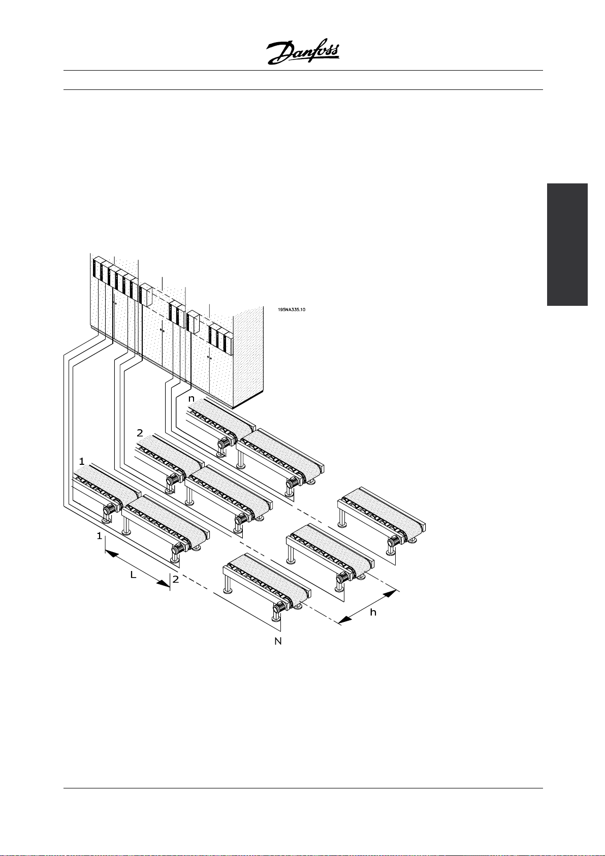
The figure illustrates an installation with motors
distributed in a number of rows with several motors in
each, as is the situation in for example parallel bottling
or baking lines in the Food and Beverage industry.
This example shows the need for power cables from
the centrally placed drives to the motors.
concept
The decentral
Centralized installation
The drives are distributed equidistant with the distance
L between each drive and the distance h between each
row and also with a distance h from the centralized
power entry/cabinet location to the first row. There
are n rows, and N drives in each row.
MG.90.F2.22 - VLT is a registered Danfoss trademark
7
Page 8
Decentral Solutions
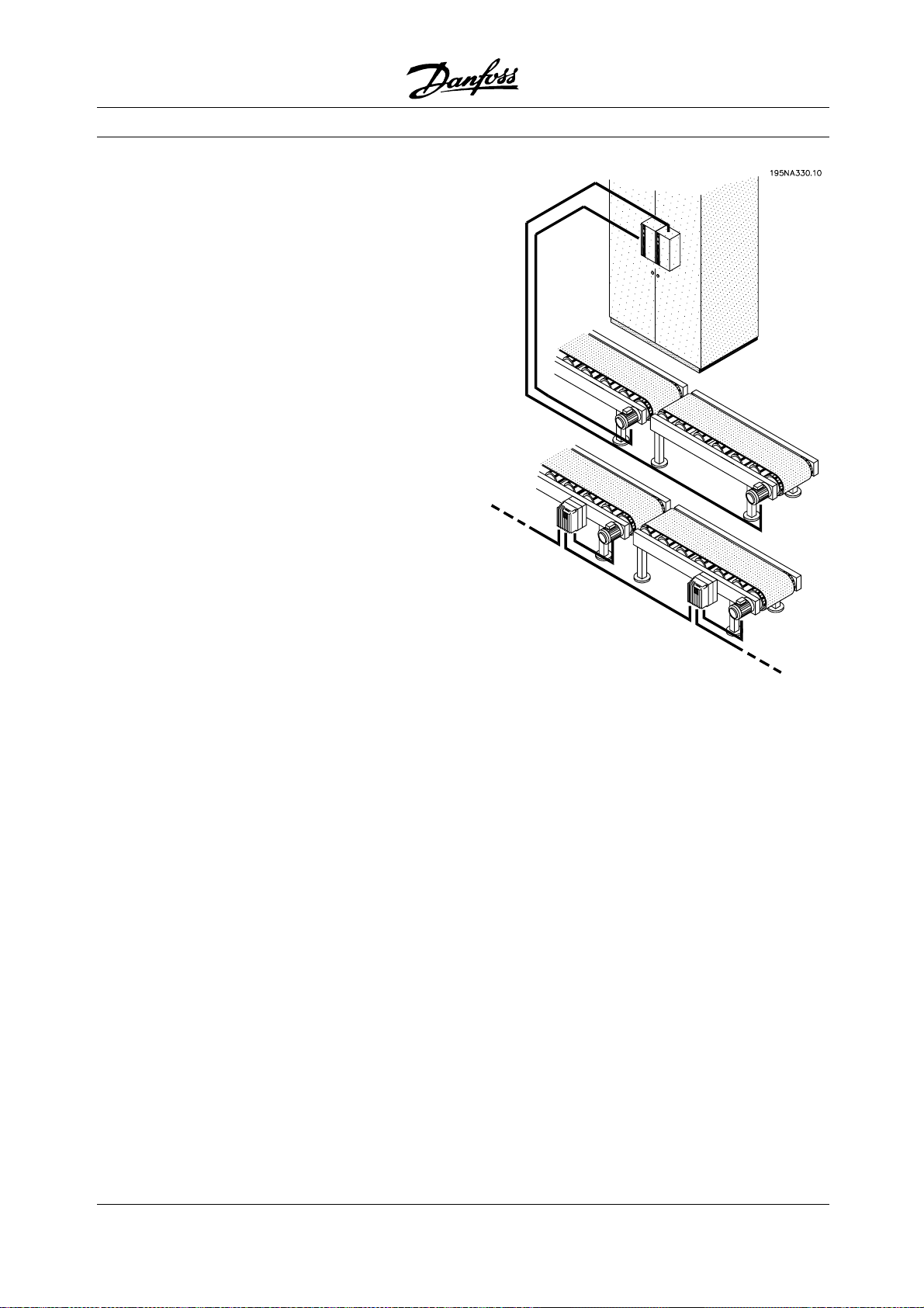
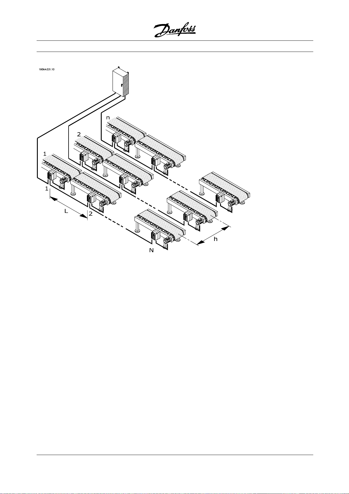
Decentralized cabling
The figure illustrates how the three-phase power
cable can be distributed with power looping from one
motor (drive) to the next. The cable saving potential is
illustrated in figure 4. Given a distance of 33 ft (10m)
between each motor and 66ft (20m) between each line,
the potential cable savings as a function of the number
of motors and number of lines shows of the figure.
Cable saving potential in an illustrative installation
The saving potential in power cable length alone
is substantial. The figure only illustrates the
potential concerning power cables. Issues like
unshielded/shielded cables and cable dimensions also
adds to the benefits of decentralized installations.
Real case
Calculations on a specific, typical bottling line with 91
pieces of 1.5 HP (1.5 kW) motors, taking the cable
dimensioning into account, showed the following
saving potential in cables and terminations:
• Cable terminations are reduced from 455 to 352
• EMC cable terminations are reduced from
364 to 182 by using motor controls with
integrated service switches
• Power cable length reduced from 21,220 ft
(6468m) to 3870ft (1180m), a reduction of 17,350ft
(5288m), and it is converted from shielded cables
to standard installation cables
For details consult the following chapter on
Good installation practice.
■Minimal need for additional fieldbus cables
Power cable savings are not offset by the additional
cost for expensive fieldbus cables. Fieldbus cables
will be extended in a decentralized installation, but
since fieldbus cables will be distributed in the plant
anyway to connect sensors or remote I/O-stations,
the extension will be limited. Decentralized products
from Danfoss can even be used as remote I/O
8
MG.90.F2.22 - VLT is a registered Danfoss trademark
Page 9
Decentral Solutions
stations to connect sensors to the fieldbus and
reduce direct costs even more.
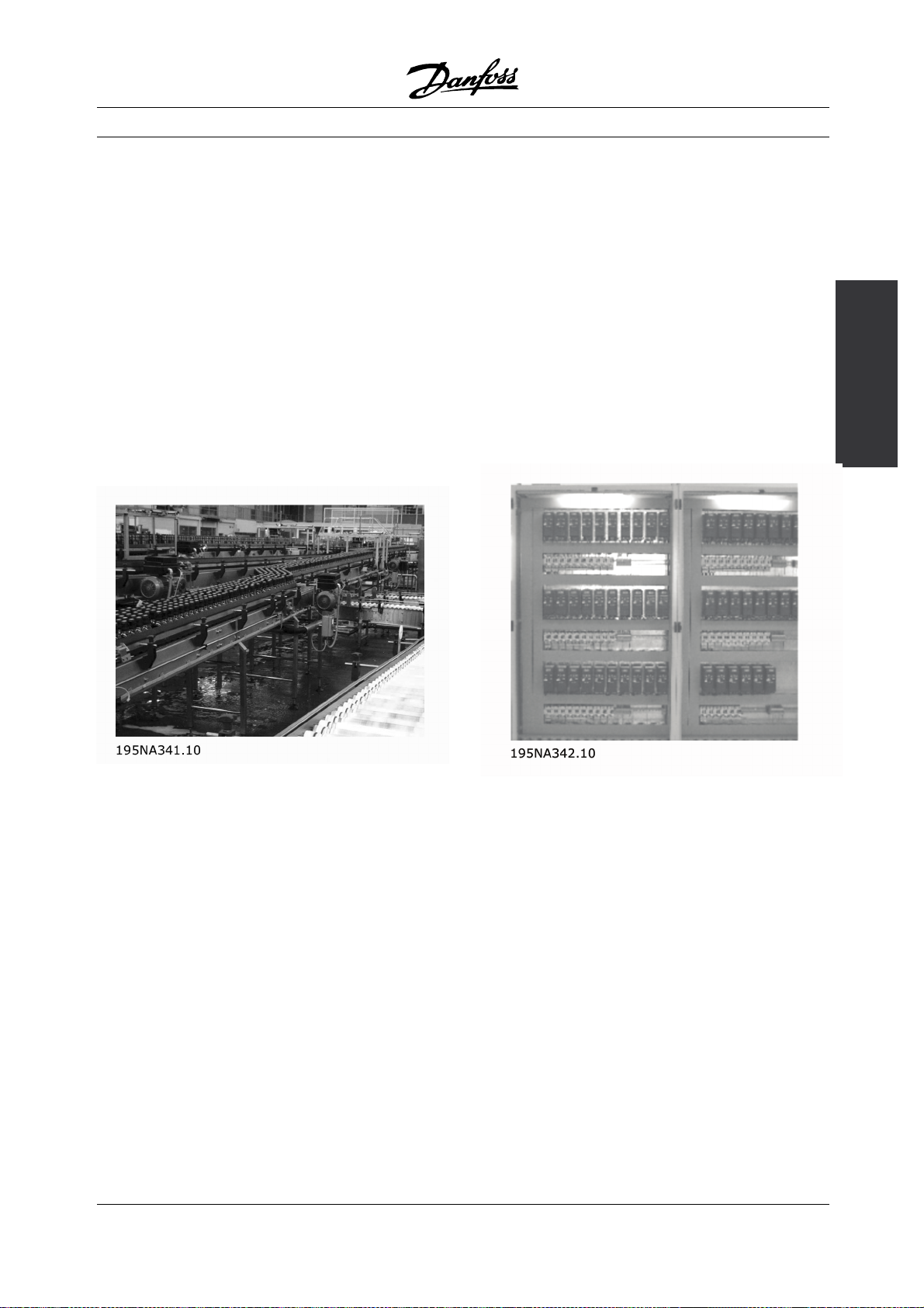
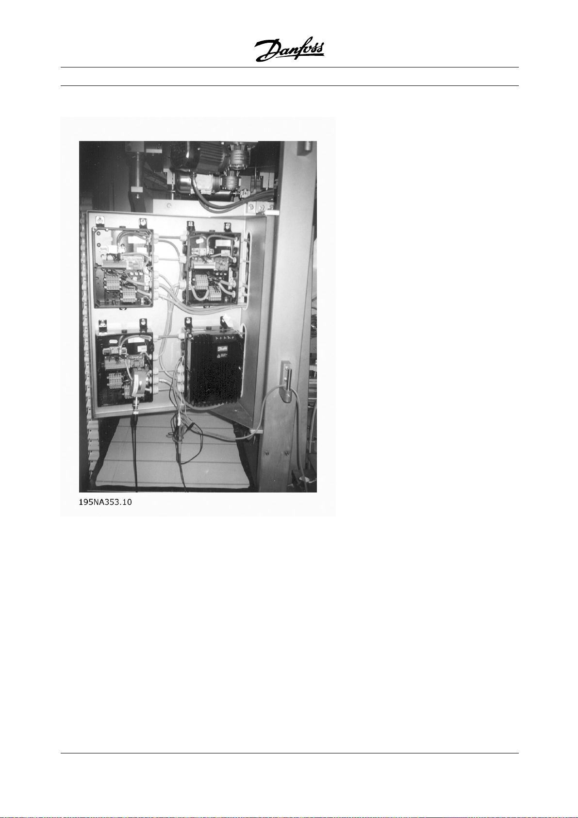
Fewer cabinets, cooling and cabletrays
Further savings will result from smaller cabinets, less
cabinet cooling and fewer cable trays. Motor controls
generate heat and are often mounted side by side
due to limited space, as illustrated in Figure 6. Forced
cooling is therefore required to remove the heat.
Less Commissioning
Time spent commissioning at the end-user is
significantly reduced using decentralized solutions especially when fieldbus communication is combined
with decentralized motor controls.
Up to 40-50 % on the total time from design to
running production can be saved.
The concept of modularization is known from
equipment like PC’s and cars. Modules with
well-described functionalities and interfaces are
used in these products. The same concept can
be applied to manufacturing, even though specific
physical constraints play a role.
Production equipment is often built from different basic
building blocks, each kind employed at several places
in the installation. Examples include various types of
conveyor sections and machinery like mixers, scales,
fillers, labellers, palletizers, packaging machines etc.
concept
The decentral
Decentralized brewery installation
An Australian brewery has installed a line of 96
decentralized drives from Danfoss connected by
DeviceNet. An excessive amount of time was saved
as the commissioning of the v ariable speed drives
was done in a few days. The brewery estimates
a saving exceeding AUD 100,000 compared to
traditional centralized installation.
■Design savings
End users want to postpone the final decision for new
equipment - and to start production as fast as possible
once a decision has been made. Payback time and
time to market must be reduced. This squeezes both
the design phase and the commissioning phase.
Modularization can minimize lead-time. Even
manufacturers of large production equipment
or lines use modularization to reduce lead-time.
MG.90.F2.22 - VLT is a registered Danfoss trademark
Centralized cabinet
In a truly modular machine, all basic elements are
self-confined and need nothing but electricity, water,
compressed air or similar to function.
Modularization therefore requires the distribution of
intelligence to the individual sections and modules.
Sure, centralized installations can be modularized,
but then motor controls will be physically separated
from the rest of the module.
■Ready-installed intelligence
The function of machinery and applications is typically
tested at the suppliers. Machines are built, tested,
calibrated and taken apart for transportation.
The process of rebuilding the application at the
production site is considerably simplified by shipping
9
Page 10
it in modules with built-in motor controls, as rewiring
and testing is time consuming and calls for skilled
personnel. Using ready-installed, decentralized
installations reduces both time and risk as wiring for
motor, control and sensors are already in place and
maintained during transportation. The need for highly
skilled experts is reduced and local labour can do a
larger part of the installation. The commissioning costs
and OEM resources on-site will be reduced.
■Improved EMC
Electrical noise emitted is proportional to cable
length. The very short - or eliminated - cable
between motor control and motor in decentralized
installations therefore reduces emitted electrical noise.
In decentralized installations, the machine builder
normally mounts cables between motor controls and
motors in the machine leaving only power cables
and fieldbus cables with no EMC emission to be
installed at the production site. The risk of electrical
noise from motor controls to disturb other electrical
equipment caused by a faulty installation will diminish
and you avoid time-consuming fault finding in the
commissioning phase, where time frame is tight.
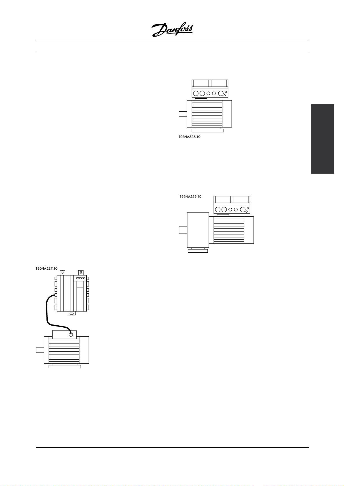
■Adapts to standard and special motors
Danfoss’ decentralized motor controls, FCD 300
and DMS 300, are designed to control standard AC
asynchronous motors. Their flexibility allows them
also to adapt to special motor types. An example
istheAMTfeature(AutomaticMotorTu
FCD 300. Combining Danfoss adjustable frequency
drives to Danfoss geared motors makes it even
easier as they fit mechanically and
already stored in the FCD 300 memory. Combined
motor-drives are provided pre-assembled directly
from Danfoss removing the need f
fitting between motor and control.
ning) in the
the motor data are
or mechanical
Decentral Solutions
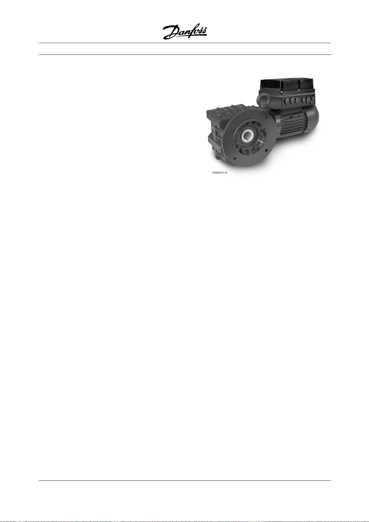
Danfoss geared motor with FCD 300
■Minimum thermal losses
Danfoss adjustable frequency drives feature the
unique VVC switch principle to generate motor
voltages. Due to the VVC principle, power losses
in the motor are similar or less than the losses in a
motor connected to line. Thermal losses are minimized
and overheating is prevented. At the same time, the
VVC principle ensures nominal torque at nominal
speed and eliminates bearing currents.
Slim DC-links
It takes two steps to convert the frequency to
vary the speed of an AC motor: A rectifier and an
inverter. As the rectifier itself produces a rippled DC
voltage, a capacitor is often introduced to smooth
the voltage supplied to the inverter. A link between
rectifier and inverter with only a small capacitor to
even out the voltage is called a "slim DC link". With
a slim DC link, the inverter will not be able to provide
quitethesamevoltageamplitudeassuppliedby
the line supply, leading to lower efficiency. A special
pulse-width-modulation can be used to compensate
theripplefromaslimDClink.Inthiscasetheoutput
voltage for the motor still does not reach the rated
supply voltage value leading to an over-consumption
of motor current up to 10% and this will increase the
motor heating. Low efficiency and need of an oversized
motor is the result. As torque decreases with the
square of voltage the application will be exceedingly
sensitive to load-changes and speed sensors might be
required. At start, only nominal torque is available.
10
MG.90.F2.22 - VLT is a registered Danfoss trademark
Page 11
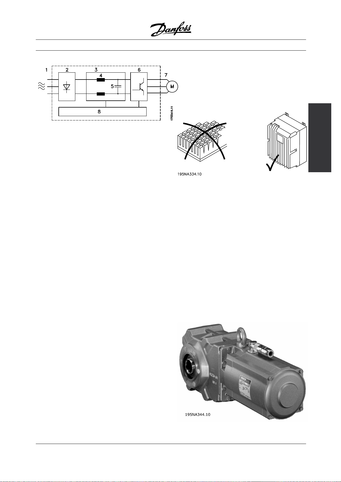
Principle of a adjustable frequency drive
using a DC link coil
The Danfoss option is to add coils to the DC link in
all drives as shown in the figure. This way a high
DC link voltage with a very low voltage ripple is
obtained and the electric strength of the drive with
regard to line transients is improved.
Further advantages are the prolonged lifetime of the
capacitors, reduced harmonic disturbance of the net
supply and presence of 150-160% start torque.
Decentral Solutions
Danfoss decentralized drives are designed to meet
the requirements as shown in Figure 9. There
are no hard-to-clean places, blind plugs have no
notches or indentations and two-layer robust surface
treatment - tested to withstand commonly used
cleaning agents - protects the housing.
concept
The decentral
Non-cleaning friendly pin fin heat sink versus
the easy to clean Danfoss solution
Numerous manufacturers of frequency inverters
use slim DC links leading to bad efficiency rates
- even if users due to the activity of for instance
the CEMEP now tend to use high efficiency
motors - meeting at least EFF2.
Danfoss’ aim is to provide high efficiency drives that
also improve the efficiency of the motors. There
should be no need for expensive over-dimensioning
and inefficient operation.
■Environmental considerations
Drives - both centrally-mounted and distributed in the
plant - are exposed to the environment. As motor
controls handle high voltages and currents at the
same time they must be protected from dust and
humidity so that they do not fail or break down. Both
manufacturers and installers must take account of this
and Danfoss Drives have designed the decentralized
products with a deep concern in both aspects.
Decentralized motor controls must also meet increasing
demands in respect of hygiene levels in pharmaceutical
industries and in food- and beverage production
in particular, where drives are exposed to cleaning
agents for extensive periods of time, high pressure
hosing and the like. The exterior of the decentralized
motor controls must be designed in such a way as
to achieve this. Complicated heat sinks as illustrated
in the figure must be avoided as it is difficult to clean
and not resistant to common cleaning agents.
All corners are rounded to prevent dust sticking, and
the distance between ribs allows high-pressure air
cleaning, hosing and easy cleaning with a brush.
These concerns are more or less irrelevant if not applied
to all elements and standard AC motors are normally
designed without these concerns in mind - stressed by
integrated fans and cooling ribs both difficult to clean.
Danfoss has met the challenge by designing a range
of aseptic geared motors. These motors have no fans
and only smooth surfaces. An IP65 enclosure class is
standard as is the special CORO coating resistant to
acid, alkali and cleaning agents used in for instance
food and beverage industry. See the photo of an
example of the aseptic geared motor series.
Aseptic Danfoss geared motor
MG.90.F2.22 - VLT is a registered Danfoss trademark
11
Page 12
Electrical contact can cause galvanic corrosion under
wet or humid conditions. This can occur between
housing (Aluminium) and screws (stainless steel). One
possible consequence is that screws become stuck
and therefore impossible to unfasten in a maintenance
situation. Galvanic corrosion will not be found on
Danfoss decentralized products, as the housings
are fully coated and nylon washers underneath
the screws protects the coating. The complete
coating and the unique gasket design prevent pitting
corrosion, which can occur under gaskets.
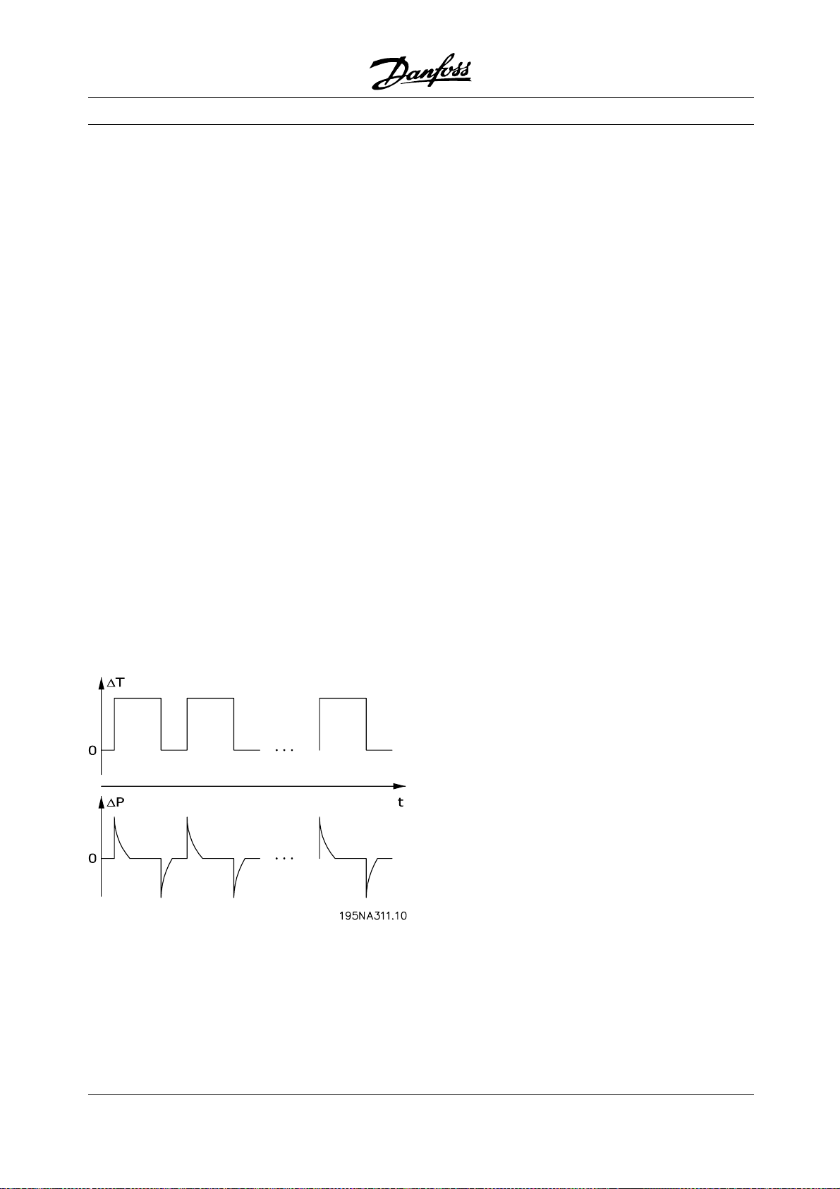
Tightly enclosed equipment is susceptible to water
build-up inside the enclosure. This is especially the case
where equipment is exposed to ambient temperature
differences under wet conditions. As a decreasing
ambient temperature lowers the surface temperature
inside the enclosure, water vapor tends to condensate.
At the same time pressure inside the enclosure will
drop and cause humid air from the outside to penetrate
non-hermetic polymer gasket materials and cable
glands. When the enclosure heats up again, only the
vaporized water will escape, leaving more and more
condensed water inside the enclosure. This can lead
to water build-up inside the enclosure and eventually
cause malfunction. The phenomenon is illustr
the figure, with a cyclic temperature fluctuation.
ated in
Decentral Solutions
material is offered by Danfoss to eliminate this problem.
The cable gland should be used in applications
exposed to frequent temperature fluctuations and
humid environments as in equipment used only during
daytimewheretheinsidetemperaturetendstofallto
the ambient temperature during the night.
■Installation flexibility
Danfoss decentralized solutions offers exceptional
installation flexibility. Flexibility is supported
by a number of benefits:
• Mountable on Danfoss geared motors
• Decentralized panel mounting possible
• Handheld control panels
• PC software for configuring and logging
• Single or double-sided installation
• Service switch optional
• Brake chopper and resistor optional
• External 24 V backup supply optional
• M12 connections for external sensors optional
• Han 10E motor connector optional
• Fieldbus support (Profibus DP V1, DeviceNet,
As-Interface)
• Compatibility with standard AC supply systems
(TN, TT, IT, delta grounded)
For further details see the chapter on The
decentralized product range.
The pumping effect in tight enclosures
Build-up of water inside enclosures can be prevented
by membranes that prevents fluids to penetrate but
allows for vapor to pass, as known from fabrics used for
outdoor clothing. A special cable gland with this kind of
12
MG.90.F2.22 - VLT is a registered Danfoss trademark
Page 13
Decentral Solutions
■Application Examples
Danfoss has completed a wide range of applications
in many different industries. This has given us a
valuable experience that has influenced the latest
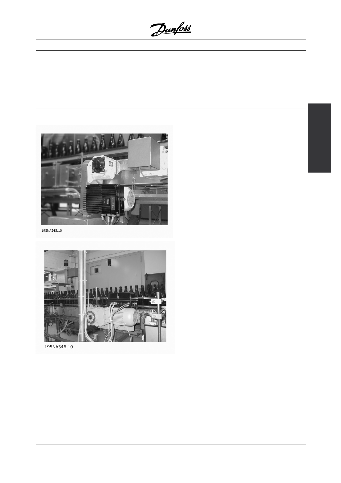
■Beverage - Bottling line
development of our decentralized products. In
the following we provide illustrative examples of
actual installations using Danfoss decentralized
products, and the benefit and value these provide
for the customer in these installations.
concept
The decentral
FCD 300 on bottling conveyor
Benefits:
• Reduced switchboard space as all drives
are mounted in the field
• Reduced cabling as several drives can be
supplied from same circuit
• Ease of commissioning over the fieldbus as the
protocol allows for transfer of complete parameters.
MG.90.F2.22 - VLT is a registered Danfoss trademark
Once one drive is set up, its basic program can
be copied to any other decentralized drive
• The FCD motor performance is markedly
superior to all other types
• The FCD can be retrofitted to existing motors
of nearly any brand or type
• The aseptic IP 66 enclosure is ideal for damp
bottling hall conditions
13
Page 14

• All in one box: e.g. service switch, Profibus
and power looping
Decentral Solutions
14
MG.90.F2.22 - VLT is a registered Danfoss trademark
Page 15
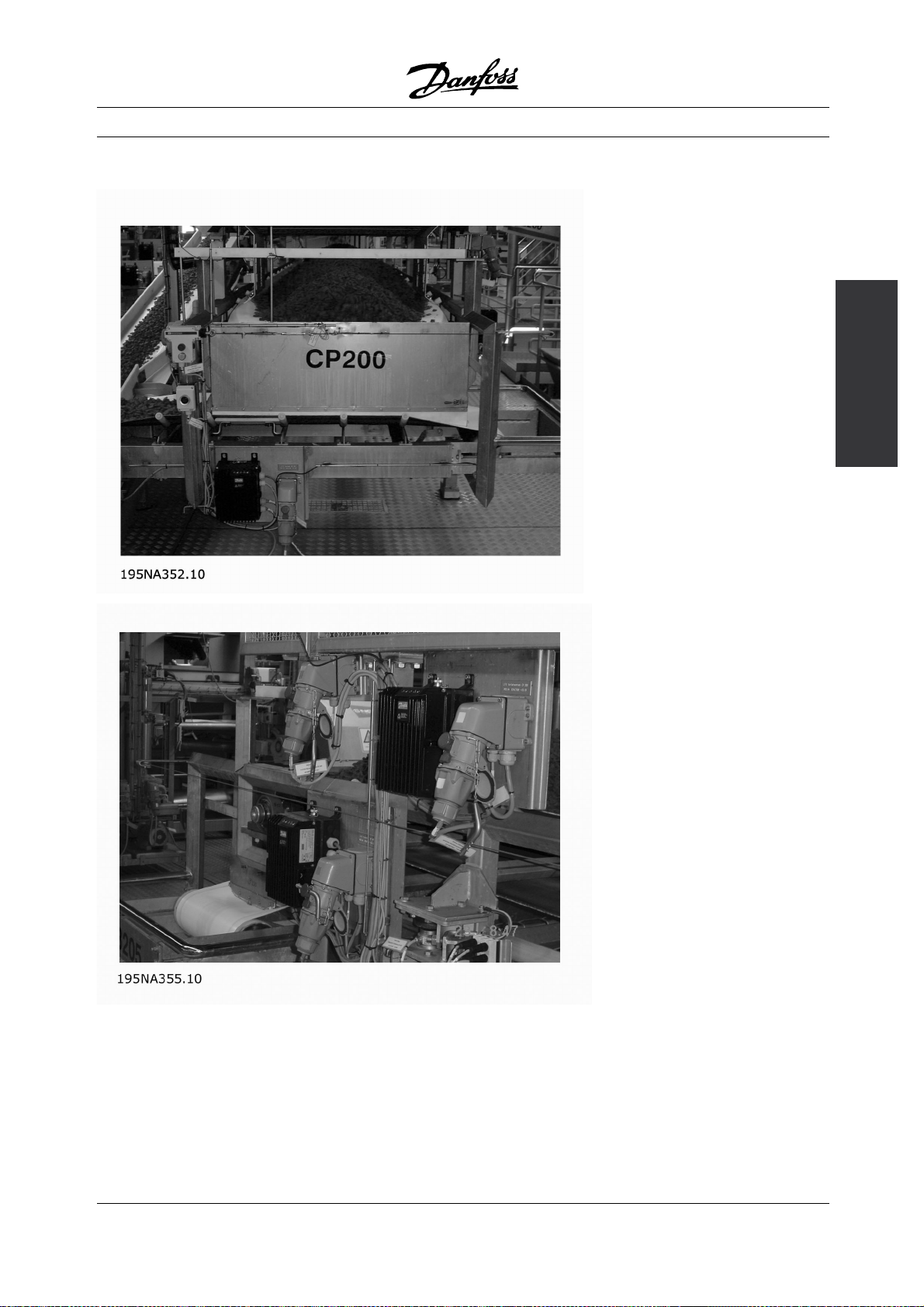
■Beverage - Packaging machine
Decentral Solutions
concept
The decentral
Decentral motor controls integrated in packaging machine
Benefits:
• Distributing motor controls in the application releases
space for other purposes in the switchboard
• The number of drives in an application can be
increased without extending the switchboard
• IP66 enclosure, easy to clean and resistant
to strong cleaning liquids
• Same flexibility as with centrally mounted
motor controls. Decentralized motor controls
can be adapted for all standard AC motors,
and feature same user interface and same
numbers on connectors
• Profibus integrated
MG.90.F2.22 - VLT is a registered Danfoss trademark
15
Page 16
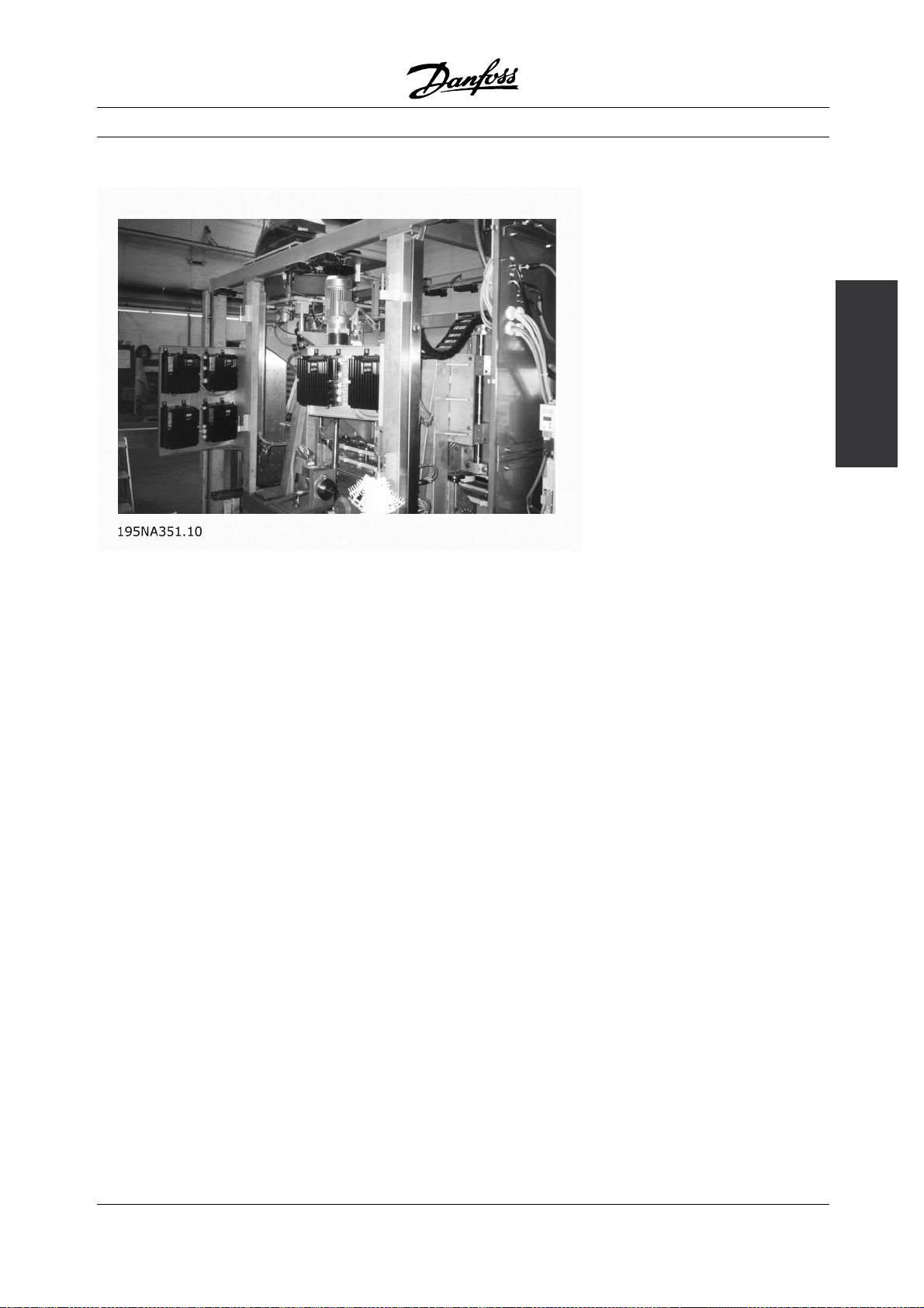
■Food - Cocoa powder plant
Old solution: Motor control - panel mounted decentrally
Decentral Solutions
New Solution: Genuine decentralized motor control
Benefits:
• Easy to expand plant capacity
• No need for switchboard
• Visible LED for status
• Service switch integrated in the unit
• High enclosure rating IP66
• Low cost installation
• Less space needed for the new solution
16
MG.90.F2.22 - VLT is a registered Danfoss trademark
Page 17
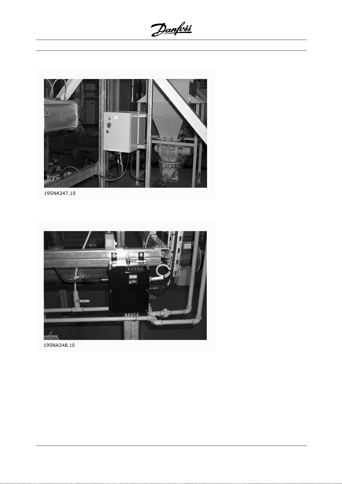
■Food conveyor
Decentral Solutions
concept
The decentral
Efficient space utilisation in the food industry with decentralized motor controls from Danfoss
Benefits:
• The number of drives in an application can be
raised without extending the switchboard
• IP66 enclosure, easy to clean and resistant
to strong cleaning liquids
MG.90.F2.22 - VLT is a registered Danfoss trademark
• Dirt-repelling surface and design prevents dirt
and product remains on the drive
• Motor or wall mount units available
• Same flexibility as with centrally mounted motor
controls. Decentralized motor controls adapt to all
17
Page 18

standard AC motors, features same user interface
and same numbering on connectors
• Profibus integrated
• Connectors for fast service integrated in
the installation box
Decentral Solutions
18
MG.90.F2.22 - VLT is a registered Danfoss trademark
Page 19
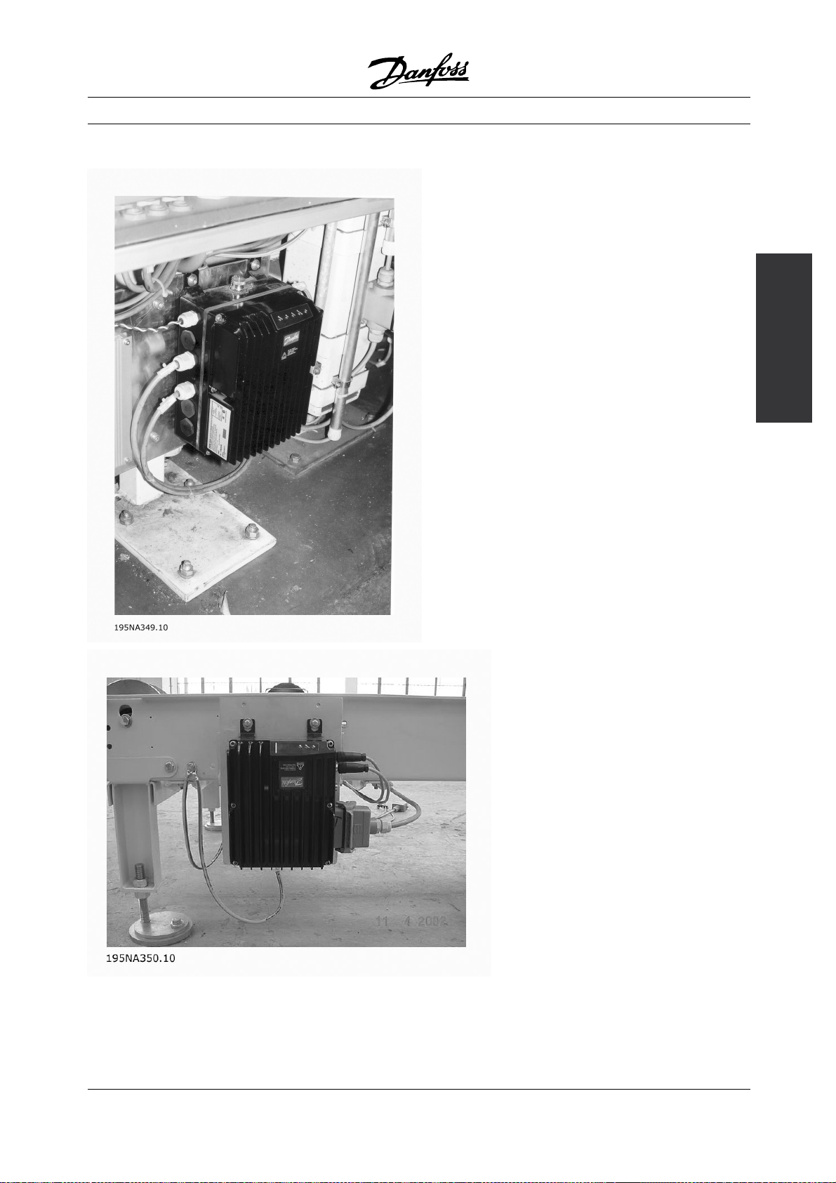
■Automotive Industry - Hoists and conveyors Benefits:
• Simple installation
• AS-i or Profibus control optional
• Sensor input available within the physical
size of the unit
• Separate 24V supply for sensors and bus
• Brake supply and control build in
• Easy pluggable remote control panel
• Connectors for looping (T-connector) integrated
in the installation box
• Low installation and component costs
• No additional and expensive EMC
connectors needed
• Compact and space saving
• Easy to install and commission
• Input for motor thermistor monitoring
Decentral Solutions
concept
The decentral
Decentral installation in the automotive industry
MG.90.F2.22 - VLT is a registered Danfoss trademark
19
Page 20
■Retrofit in existing applications
Decentral Solutions
Retrofitting on existing application with speed control
Benefits:
• No need for a big control cabinet thanks to
the decentralized motor controls.
• No expensive wiring: All motors use existing
power cables, pipes and local switches
• All motor controls can be controlled from the
existing centralized cabinet via Profibus
20
MG.90.F2.22 - VLT is a registered Danfoss trademark
Page 21
■The decentralized product range
The Danfoss decentralized concept covers motor
controls ranging from motor starters/soft starters
to variable frequency drives.
Motor starters and soft starters (DMS 300) make
start and stop of your application smoother and
smarter than ordinary DOL (Direct On Line) operation
but do not affect operation further.
Variable frequency drives (FCD 300) are used
for following requirements:
• Adjustable speed
• Precise speed
• Defined speed ramps at start or/and stop
• Shorter stop times (braking)
Danfoss decentralized motor controls range from
0.24HP(0.18kW)to4HP(3kW)(connectstoup
to 5 HP (4 kW) motors). This chapter lists several
optional features and accessories available.
Decentral Solutions
2. Mounted directly on the motor ("motor-mounted")
• Fair choice of motor brands
• No need for shielded motor cable
3. "Pre-mounted" on Danfoss Bauer
geared motors
concept
The decentral
■Flexible installation options
Danfoss decentralized motor controls FCD 300 and
DMS 300 series can be adapted for mounting using
the following options - each offering specific benefits:
1. Stand alone close to the motor ("wall-mounted")
• Free choice of motor brand
• Easy retrofitting to existing motor
• Easy interfacing to motor (short cable)
• Easy access for diagnosis and optimal serviceability
• A fixed combination of motor and electronics
supplied by one supplier
• Easy mounting, only one unit
• No need for shielded motor cable
• Clear responsibility regarding the complete solution
As the electronic parts are common - same function
of terminals, similar operation and similar parts
and spare parts for all drives - you are free to
mixthethreemountingconcepts.
MG.90.F2.22 - VLT is a registered Danfoss trademark
21
Page 22

Decentral Solutions
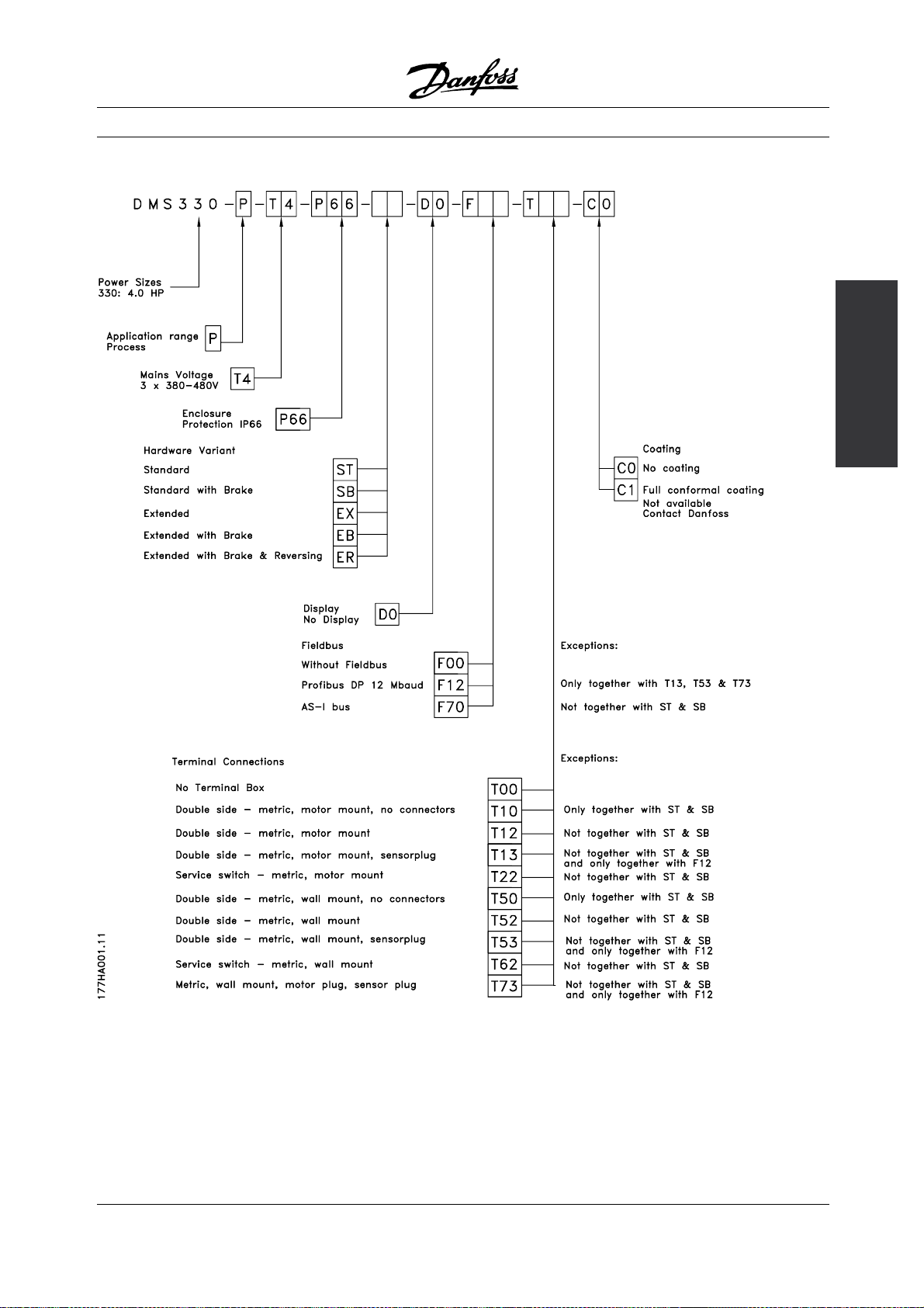
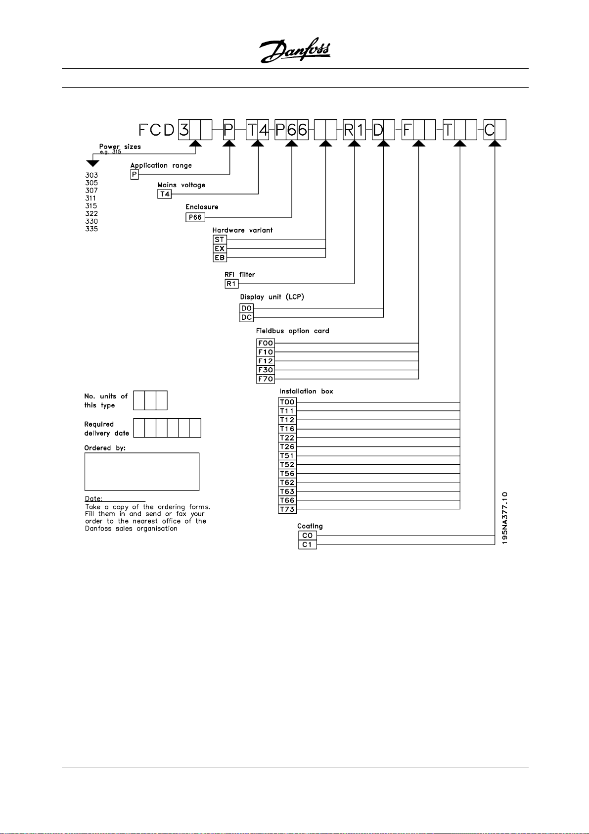
■Configuring a product
The decentralized motor controls DMS 300 and
FCD300seriesareconfiguredwithatypecode
string (see also Ordering):
DMS 330 P T4 P66 XX D0 Fxx Txx C0
FCD 3xx P T4 P66 R1 XX Dx Fxx Txx C0
Electrical voltage
DMS 300/FCD 300 are available for connection to
electrical voltage 3 phase 380-480 V.
Choice of motor starter
The motor starter DMS 300 covers the whole power
range from 0.18-3 HP (kW) in one unit.
Choice of adjustable frequency drive
Theadjustablefrequencydrivemustbechosenon
the basis of the present motor current at maximum
loading of the unit. The adjustable frequency drive’s
rated output current I
must be equal to or greater
INV.
than the required motor current.
Typical shaft output
P
INV.
Type [kW] [HP] [HP]
303 0.37 0.50
305 0.55 0.75
307 0.75 1.0
311 1.1 1.5
315 1.5 2.0
322 2.2 3.0
330 3.0 4.0
335** 3.3 5.0*
* at power/motor voltage 3 x 460 - 480 V
** t
max. 95º F (35° C)
amb
■Enclosure
DMS 300 / FCD 300 units are protected against
water and dust as standard.
See also th
e section entitled Technical data
for further details.
■Brake
FCD 300 is available with or without an integral
brake m
odule. See also the section entitled Brake
resistors for ordering a brake resistor.
EB version including mechanical brake control/supply.
■24 V external supply
Back up of control supply with 24 V DC is
available in EX and EB versions.
■RFI filter
FCD 300 has an integral 1A RFI-filter. The integral
1A RFI filter complies with EMC standards EN
55011-1A. See the sections Cable lengths and
Cross section for further details.
■Harmonic filter
The harmonic currents do not affect power
consumption directly, but they increase the heat losses
in the installation (transformer, cables). That is why in
a system with a relatively high percentage of rectifier
load it is important to keep the harmonic currents at
alowlevelsoastoavoidatransformeroverloadand
high cable temperature. For the purpose of ensuring
low harmonic currents, the FCD 300 units are fitted
with coils in their intermediate circuit as standard. This
reduces the input current I
by typically 40 %.
RMS
■Display unit
OntheFCD300unitthereare5LEDsforvoltage
(ON), warning, alarm, status and bus.
In addition, a plug for connecting an LCP control panel
is available as an option. The LCP control panel can be
installed up to 9 feet away from the variable frequency
drive, e.g. on a front panel, by means of a mounting kit.
All displays of data are via a 4-line alpha-numerical
display, which in normal operation is able to show
4 operating data items and 3 operation modes
continuously. During programming, all the information
required for quick, efficient parameter Setup of the
variable frequency drive is displayed. As a supplement
to the display, the LCP has three LEDs for voltage
(ON), warning (WARNING) and alarm (ALARM).
Most of the variable frequency drive’s parameter
Setups can be changed immediately via the LCP
control panel. See also the section entitled The
LCP control unit in the Design Guide.
Desired features are selected by specifying the
corresponding fields in the string (xx). The choices -
22
MG.90.F2.22 - VLT is a registered Danfoss trademark
Page 23

and detailed explanation - shown in the two tables.
Short form explanations of a feature are u
For technical details and data, see Technical data.
■Installation box variants
Connections on right side
Gland holes for all c
ight side only (seen from motor drive end). This
r
version is useful where cable inlet is required from
one direction only (only FCD 300 series).
able inlets are machined on the
nderlined.
Decentral Solutions
Connections on two sides
Gland holes for c
allowing for cable inlet from both directions.
Both m
(selected variants).
P
looping AC line power supply between drives
(0.15 in
The bottom section contains Cage Clamp connectors
and looping facilities for power and fieldbus cables well
protected against dust, hosing and cleaning agents.
S
motor drive end). A lockable switch integrated in the
enclosure - disconnecting the motor or drive.
4s
drive end). Looping through of 2 X 24 V external supply.
Pluggable connection of remote I/O such as sens
and external supply of these.
M
from motor drive end) wired according to DESINA
standard (see electrical installation).
etric thread and NPT thread is available
luggable connection and the possibility of
2
line or 4 mm2line).
ervice switch mounted on the right side (seen from
ensor plugs, M12 on the right side (seen from motor
otor plug, HARTING 10 E on the right side (seen
able inlets are machined on both sides
ors
concept
The decentral
D
isplay connector for external pluggable
of the local control panel for operating and
programming. Can also be used for PC connection.
Only available for FCD 300.
MG.90.F2.22 - VLT is a registered Danfoss trademark
connection
23
Page 24
Decentral Solutions
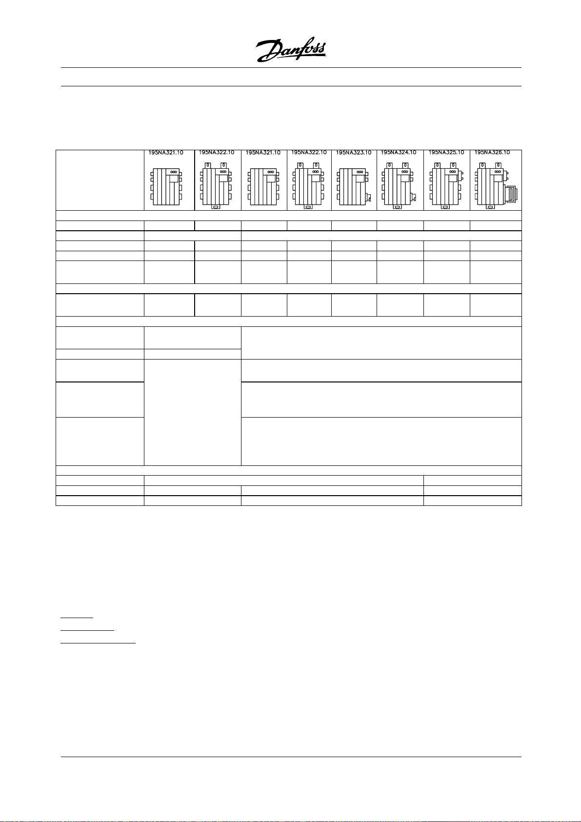
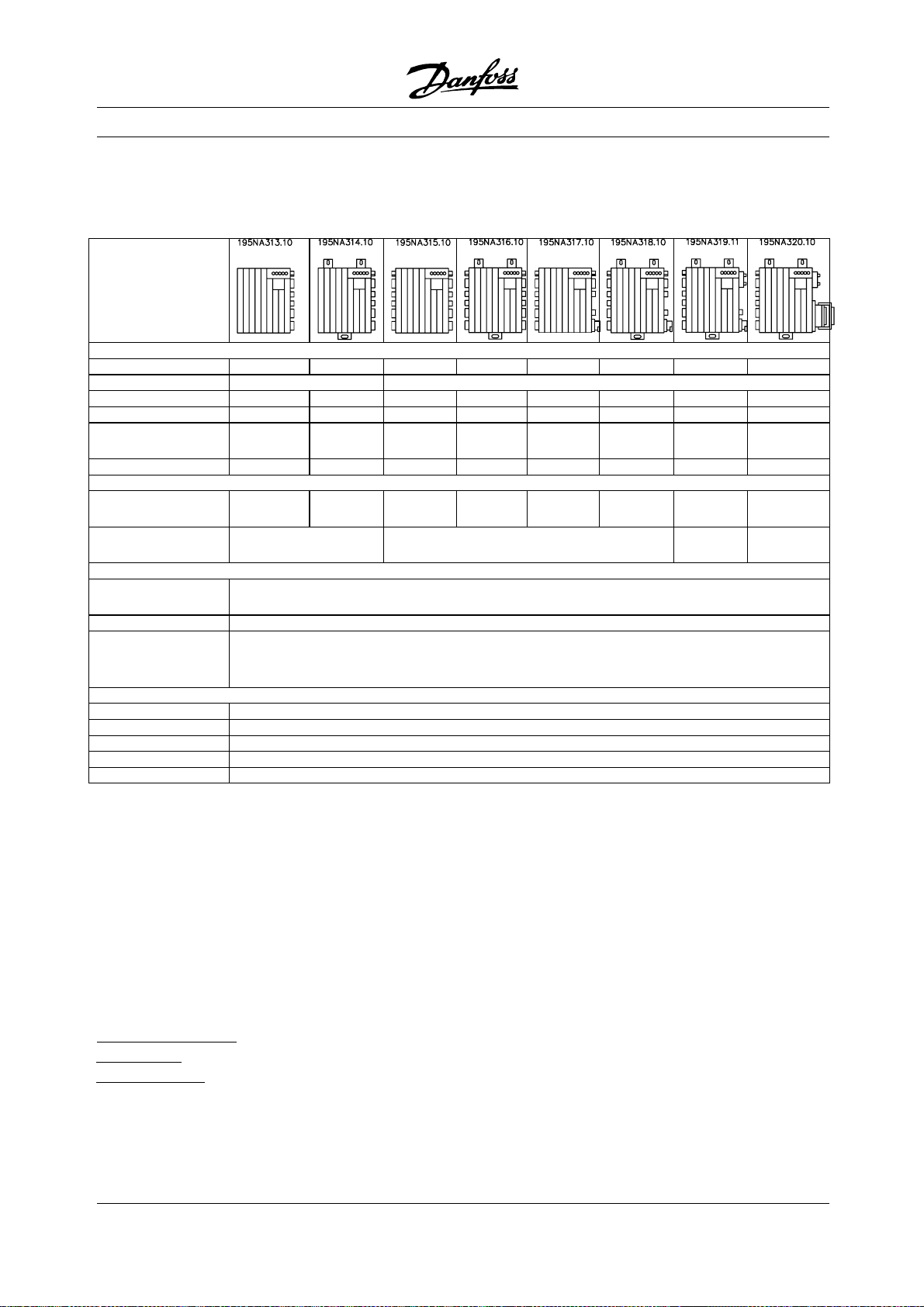
■DMS 300 Decentralized electronic Motor Starter
DMS 300 - Combinations of versions
Installation features
Mounting Motor Wall Motor Wall Motor Wall Wall Wall
Pluggable - X
Service switch - - - - X X - -
Sensor plugs - - - - - - 4XM12 4XM12
Motor plug - - - - - - - Harting
Ordering codes DMS330PT4P66XX D0 Fxx Txx C0
Metric thread
(NPT thread)
Functional features
Basic functions
(see below)
+ Brake control SB
+ Current
monitoring
+ Current
monitoring +
Brake control
+ Current
monitoring +
Brake control
+Reverse
Communication
No bus F00 -
AS-interface - F70 -
Profibus - F12* F12
T10 T50 T12
(T16)*
ST
-
T52
(T56)*
T22
(T26)*
-
EX
EB
ER
T62
(T66)*
T53 T73
10E
- = not available * contact Danfoss sales org for availability
Basic functions
Electronic start/stop of a motor
Soft start/stop
Extended functionality
everse for bi-directional operation of the motor
R
rake control and supply of electromechanical brake
B
C
urrent monitoring for electronic motor protection
24
MG.90.F2.22 - VLT is a registered Danfoss trademark
Page 25
■Ordering form - DMS 300
Decentral Solutions
concept
The decentral
MG.90.F2.22 - VLT is a registered Danfoss trademark
25
Page 26
Decentral Solutions
■FCD 300 Decentralized Adjustable Frequency Drive
FCD 300: Combinations of versions
Installation features
Mounting Motor Wall Motor Wall Motor Wall Wall Wall
Cable inlets Right side Double sided
Service switch - - - - X X X -
Sensor plugs - - - - - - 4XM12 4XM12
Motor plug - - - - - - - Harting
ATEX 22
Metric thread
(NPT thread)
Display
connector
Functional features
Basic functions
(see below)
+24ext.backup EX
+24ext.backup
+ Dynamic brake
+ Brake control
Communication
RS 485 F00
AS-interface F70
Profibus 3 MB F10
Profibus12 MB F12
DeviceNet F30
*
X X X X - - - -
Ordering codes FCD 3xx P T4 P66 R1 XX DxFxx Txx C0
T11
(-)
Not available
only D0
T51
(-)
T12
(T16)
T52
(T56)
T22
(T26)
T62
(T66)
DC DC
T63
(-)
includedDCincluded
ST
EB
10E
T73
(-)
* ATEX 22: Approved for use in dusty environments according to the ATEX directive (ATmosphère EXplosive)
Basic functions
Adjustable motor speed
Defined speed ramps - up and down
Features and operation concepts similar to
other VLT series
Electronic motor protection and reverse are
always included
Extended functionality
2
4 V external back up of control and communication
rake control and supply of electromechanical brake
B
ynamic braking (brake resistor is optional
D
see brake resistors)
26
MG.90.F2.22 - VLT is a registered Danfoss trademark
Page 27

The below explanations refer to the ordering form.
P
ower sizes (positions 1-6):
0,37 HP (kW) - 3,3 HP (kW) (See power
size selection table)
A
pplication range (position 7):
• P-process
E
lectrical voltage (positions 8-9):
• T4 - 380-480 V three phase supply voltage
E
nclosure (positions 10-12):
The enclosure offers protection against dusty,
wet, and aggressive environment
• P66 - Protected IP66 enclosure
ardware variant (positions 13-14):
H
• ST - Standard hardware
• EX - 24 V external supply for backup of control card
• EB - 24 V external supply for backup of control
card, control and supply of mechanical brake
and an additional brake chopper
R
FI filter (positions 15-16):
• R1 - Compliance with class A1 filter
Decentral Solutions
nstallation box (positions 22-24):
I
• T00 - No Installation box
• T11 - Installation box, motor mount, metric
thread, only right side
• T12 - Installation box, motor mount, metric
thread, double side
• T16 - Installation box, motor mount, NPT
thread, double side
• T22 - Installation box, motor mount, metric
thread, double side, service switch
• T26 - Installation box, motor mount, NPT thread,
double side, service switch
• T51 - Installation box, wall mount, metric
thread, only right side
• T52 - Installation box, wall mount, metric
thread, double side
• T56 - Installation box, wall mount, NPT
thread, double side
• T62 - Installation box, wall mount, metric thread,
double side, service switch
• T66 - Installation box, wall mount, NPT thread,
double side, service switch
• T63 - Installation box, wall mount, metric thread,
double side, service switch, sensor plugs
• T73 - Installation box, wall mount, metric thread,
double side, motor plug, sensor plugs, Viton gasket
concept
The decentral
D
isplay unit (LCP) (positions 17-18):
Connection possibility for display and keypad
• D0 - No pluggable display connector in the unit
• DC - Display connector plug mounted (not available
with "only right side" installation box variants)
F
ieldbus option card (positions 19-21):
A wide selection of high performance fieldbus
options is available (integrated)
• F00 - No fieldbus option built in
• F10 - Profibus DP V0/V1 3 Mbaud
• F12-ProfibusDPV0/V112Mbaud
• F30 - DeviceNet
• F70 - AS-interface
C
oating (positions 25-26):
The IP66 enclosure offers protection of the drive against
aggressive environments, which practically eliminates
the need for coated printed circuit boards.
• C0 - Non-coated boards
MG.90.F2.22 - VLT is a registered Danfoss trademark
27
Page 28
■Ordering form - FCD 300
Decentral Solutions
28
MG.90.F2.22 - VLT is a registered Danfoss trademark
Page 29
Decentral Solutions
■PC Software tools
PC Software - MCT 10
All drives are equipped with a serial communication
port. We provide a PC tool for communication
between PC and adjustable frequency drive, VLT
Motion Control Tool MCT 10 Set-up Software.
MCT10Set-upSoftware
MCT 10 has been designed as an easy-to-use
interactive tool for setting parameters in our
adjustable frequency drives.
The MCT 10 Set-up Software will be useful for:
• Planning a communication network off-line.
MCT10containsacompleteadjustable
frequency drive database
• Commissioning adjustable frequency drives on line
• Saving settings for all adjustable frequency drives
• Replacing a drive in a network
• Expanding an existing network
• Future developed drives will be supported
MCT 10 Set-up Software support Profibus DP-V1 via
a Master class 2 connection. It makes it possible to
on-line read/write parameters in a adjustable frequency
driveviatheProfibusnetwork. Thiswilleliminatethe
need for an extra communication network.
The MCT 10 Set-up Software Modules
The following modules are included in the
software package:
MCT10Set-upSoftware
Setting parameters
Copy to and from adjustable frequency
drives
Documentation and print out of
parameter settings incl. diagrams
SyncPos
Creating SyncPos program
Ordering number:
Please order your CD containing MCT 10 Set-up
Software using code number 130B1000.
concept
The decentral
■Accessories for DMS 300 and FCD 300
Type Description Ordering no.
LCP2 control unit FCD LCP2 for programming the adjustable frequency
175N0131
drive
Cable for LCP2 control
FCD Cable from LCP2 to adjustable frequency drive 175N0162
unit
LCP2 remote-mounting
kit
LOP (Local Operation
Pad)
FCD Kit for remote-mounting of LCP2 (incl. 39 in.
cable, excl. LCP2)
FCD LOP can be used for setting the reference
and start/stop via the control terminals
175N0160
175N0128
Motor adaption plate DMS/FCD Plate for adapting to non Danfoss Bauer motors 175N2115
Membrane DMS/FCD Membrane for preventing condensation 175N2116
Plug kit for LCP2 FCD Plug for LCP2 for mounting in the terminal box. 175N2118
Motor star terminal DMS/FCD Terminal for interconnection of motor wires (star
175N2119
point)
Installation kit FCD Installation kit for mounting in panels 175N2207
M 12 plug FCD E.g. for DeviceNet 175N2279
Viton Gasket FCD 303-315 Painting shop compatible 175N2431
Viton Gasket FCD 322-335 Painting shop compatible 175N2450
Data Cable FCD For PC communication 175N2491
Motor mounting adaptor 175N2115
Aluminium plate with holes drilled to fit the FCD/DMS
box. Must be fitted locally for the actual motor.
LCP2 connection 175N2118 (for the FCD
300 series)
MG.90.F2.22 - VLT is a registered Danfoss trademark
29
Page 30

The installation box can be mounted with or without
a sealed connector (IP66) to connect the common
display LCP2 (code DC). The connector can be ordered
separately (Not for single sided installation boxes).
LCP2 keyboard/Display 175N0131 (for
the FCD 300 series)
Alphanumeric display for programming the
adjustable frequency drive.
Cable for LCP2 175N0162 (for the FCD 300 series)
Preconfectioned cable to be used between adjustable
frequency drive and LCP2.
Data cable for PC communication 175N2491
(for the FCD 300 series)
connects a drive (e.g. USB) to the LCP2 connector.
Remote mounting kit for LCP2 175N0160
(for the FCD 300 series)
Kit for permanent mounting of the LCP2 in an enclosure.
Decentral Solutions
5 pole M12 plug for AS-interface 175N2281
The plug, M12, can be mounted into the gland
holes of the installation box.
Viton Gasket for FCD 303-315 175N2431
With this gasket the FCD can be used in painting
shops in e.g. the automotive industry.
Viton Gasket for FCD 322-335 175N2450
With this gasket the FCD can be used in painting
shops in e.g. the automotive industry.
■Ordering numbers for brake resistors
Internally mountable brake resistors for low duty cycle
braking (1-3%). The resistors are self-protecting.
Internal brake resistors cannot be mounted in
FCD 303-315 with service switch.
Venting membrane 175N2116
Membrane preventing water build-up due to
condensation inside enclosures.
Star point terminal 175N2119
Six wires must be either star- or delta-connected to
supply an AC motor. Delta connection is possible
in the standard motor terminal. Star connection
requires a separate terminal.
5 pole M12 plug for e.g. DeviceNet 175N2279
(for the FCD 300 series)
The plug, micro type, M12 can be mounted into the
gland holes of the installation box. The plug can also be
used for other purposes such as connection of sensors.
6.5ft (2m) drop cable for DeviceNet 195N3113
(for the FCD 300 series)
The cable can be mounted inside the terminal
box, and connects to the DeviceNet trunk line
via a micro connector (M12).
Type Description Ordering no.
Internal brake resistor FCD 303-307 Brake resistor for mounting inside the terminal
175N2154
box
Internal brake resistor FCD 311-335 Brake resistor for mounting inside the terminal
175N2117
box
30
MG.90.F2.22 - VLT is a registered Danfoss trademark
Page 31
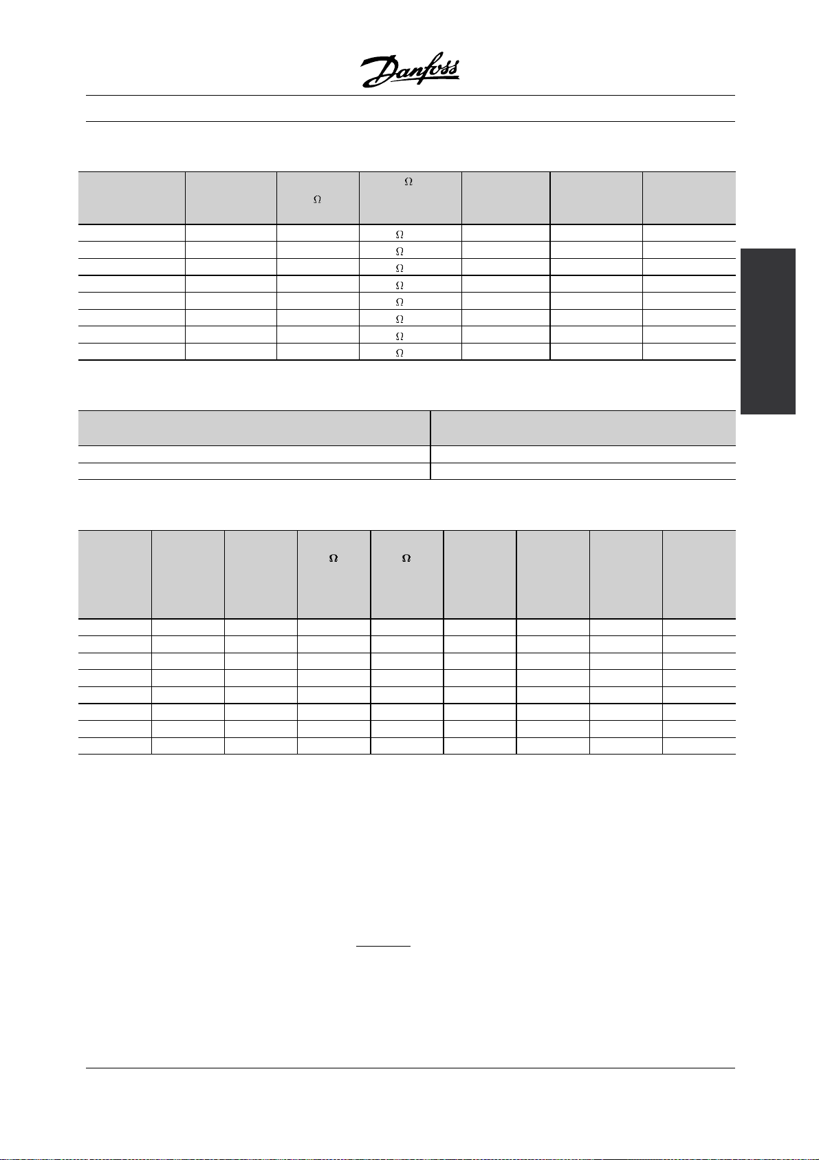
Flatpack brake resistors IP 65
Decentral Solutions
Ty pe P
303 (400 V) 0.37 520 830 / 100 W 20 1000 2397
305 (400 V) 0.55 405 830 / 100 W 20 1000 2397
307 (400 V) 0.75 331 620 / 100 W 14 1001 2396
311 (400 V) 1.10 243 430 / 100 W 8 1002 2395
315 (400 V) 1.50 197 310 / 200 W 16 0984 2400
322 (400 V) 2.20 140 210 / 200 W 9 0987 2399
330 (400 V) 3.00 104 150 / 200 W 5.5 0989 2398
335 (400 V) 3.30 104 150 / 200 W 5.5 0989 2398
motor
[kW] [HP]
R
MIN
[ ]
Size [ ]/[W]
per item
Duty cycle % 2wires
Order no.
175Uxxxx
Shielded cable
Order no.
175Nxxxx
Mounting bracket for brake resistors
Ty pe Order no.
175Nxxxx
303-315 2402
322-335 2401
Coiled wire brake resistors Duty-cycle 40%
VLT Type Intermit-
tent brak-
ing period
time
[seconds]
303 (400 V) 120 0,37 520 830 0,45 0,7 1976 1,5*
305 (400 V) 120 0,55 405 830 0,45 0,7 1976 1,5*
307 (400 V) 120 0,75 331 620 0,32 0,7 1910 1,5*
311 (400 V) 120 1,1 243 430 0,85 1,4 1911 1,5*
315 (400 V) 120 1,5 197 330 0,85 1,6 1912 1,5*
322 (400 V) 120 2,2 140 220 1,00 2,1 1913 1,5*
330 (400 V) 120 3,0 104 150 1,35 3,0 1914 1,5*
335 (400 V) 120 3,3 104 150 1,35 3,0 1914 1,5*
P
motor
[kW] [HP]
R
[ ]
min
R
[ ]
rec
P
b, max
[kW] [HP]
Therm.re-
lay
[Amp]
Code
number
175Uxxxx
Cable
cross
section
2
[
]
concept
The decentral
*Always observe national and local regulations
P
motor
R
min
R
rec
P
b, max
: Rated motor size for VLT type
: Minimum permissible brake resistor
: Recommended brake resistor (Danfoss)
: Brake resistor rated power as stated by supplier
Therm. relay : Brake current setting of thermal relay
Code number : Order numbers for Danfoss brake resistors
Cable cross section : Recommended m
inimum value based upon PVC insulated cober cable, 86
degrees Fahrenheit (30 degree Celsius) ambient temperature with normal heat
dissipation
See dimensions of Coiled wire brake resistors in instructions MI.90.FX.YY
MG.90.F2.22 - VLT is a registered Danfoss trademark
31
Page 32

Externally mounted brake resistors in general
No use of aggressive cleaning solvents. Cleaning
solvents must be pH neutral.
See Dynamic braking for dimensioning of
brake resistors.
Decentral Solutions
32
MG.90.F2.22 - VLT is a registered Danfoss trademark
Page 33

Decentral Solutions
■Information and communication
Growth in the world of automation is increasingly
based on information technology. Having reformed
hierarchies, structures and flows in the entire office
world, use of information technology opens for a
similar restructuring of industrial sectors ranging
from process and manufacturing industries to
logistics and building automation.
Devices capability of communication and continuous
transparent channels for information are indispensable
in automation concepts of the future.
IT is an evident means for optimisation of system
processes, leading to improved exploitation of
energy, materials and investment.
Industrial communication systems are a key
function in this respect.
Cell level
Programmable controllers such as PLC and IPC
communicate at cell level. Large data packets
and numerous powerful communication functions
provide information flow. Smooth integration into
company-wide communication systems, such
as Intranet and Internet via TCP/IP and Ethernet
are important requirements.
Field level
Distributed peripherals such as I/O modules, measuring
transducers, drive units, valves and operator terminals
communicate with the automation systems via an
efficient, real-time communication system at field level.
Transmission of process data is performed in cycles,
while alarms, parameters and diagnostic data have
to be transmitted acyclically if necessary.
Sensor/actuator level
Binary signals from sensors and actuators are
transmitted purely cyclically via bus communication.
■Profibus
Profibus is a vendor-independent, open field bus
standard for use in a wide range of applications
in manufacturing and process automation.
Vendor-independence and openness are ensured
by the international standards EN 50170, EN
50254 and IEC 61158.
Profibus communicates between devices from different
manufacturers without s
pecific interface adjustments
and can be used for both high-speed time critical
applications and complex communication tasks.
Due to ongoing technical developments, Profibus
is widely acknowledged as the leading industrial
communication system of the future.
More than 2,000 products from approximately 250
Profibus vendors are available today. More than
6.5 million devices representing a huge variety of
products are installed and successfully used in
more than 500,000 applications in manufacturing
and process automation.
Danfoss Drives solution offers a cost
optimal Profibus solution
• MCT-10 software tool for access via standard PC
• Simple two-wire connection
• A universal, globally-accepted product
• Compliance with the international standard
EN 50170
• Communication speed 12 Mbaud
• Access to drive master file makes planning easy
• Fulfilment of PROFIDRIVE guideline
• Integrated solution
• All variable frequency drives with Profibus are
certified by the Profibus organization
• Danfoss variable frequency drives support
Profibus DP V1
Profibus DP V1 for two different purposes
Fieldbus systems are used for two very different
purposes with two very different sets of essentials in
modern automation applications. One is transfer of
signals referring to the process itself, the other service,
commissioning and set-up communication.
Transfer of control and status signals between sensors
and actuators is time critical and must be processe
reliably and in real time. This is accomplished by
cyclic communication where each node in the network
is polled within each cycle, and each cycle has a
pre-defined time. It is necessary to pre-define and
minimize the extent of data in each telegram to make
this work reliably and as fast as possi
This consideration contradicts the second use of the
fieldbus, namely as a timesaving set-up and diagnostics
bus. Set-up and diagnostics are not time-critical, not
continuously used, and require a larger amount of data
in each telegram. Furthermore, you would tend to
control this information from a PC or an interface device
ble.
d
concept
The decentral
MG.90.F2.22 - VLT is a registered Danfoss trademark
33
Page 34

Decentral Solutions
(HMI) - and not from the master (typically a PLC) that
controls the cyclic communication. Standard Profibus
does not support networks with several masters so
set-up and diagnostics information must be contained
in the standard telegram handled by the master,
making for very long and time-consuming telegrams
with room for information only sporadically used.
Profibus DP V1 now combines the two sets of
requirements from above in a single fieldbus system,
allowing a second master to use the entire network
in a specified time slot in each cycle. Profibus DP
V1 thus operates with two classes of masters.
Masterclass 1 (typically a PLC) performs the cyclic
communication. Masterclass 2, typically an interface
device (HMI or PC), transfers non-time critical
information through non-cyclic communication.
Masterclass 2 masters can be connected anywhere
on the Profibus net and the communication channel
can be opened and closed anytime without disturbing
the cyclic communication. You can have non-cyclic
communication even without cyclic communication to
for instance transfer complete programs or set-ups.
the broadcast-oriented, communications protocol
CAN (Controller Area Network).
The CAN protocol was originally developed for the
European automotive market to be used in exchange
for expensive wire harnesses in automobiles. As
a result, the CAN protocol offers fast response
and high reliability for demanding applications
like ABS brakes and air bags.
Danfoss concept offers the cost optimal
DeviceNet solution
• Cyclic I/O communication
• Acyclic communication - "explicit messaging"
• Unconnected Messages Manager (UCMM)
messages are supported
• Integrated solution
• Electronic Data sheet (EDS)-files secures
easy configuring
• Provides fieldbus voltage supply
• Fulfilment of DeviceNet AC/DC motor profile
• Protocol defined in accordance with the Open
DeviceNet Vendor Association (ODVA)
Profibus DP V1 is fully compatible with prior versions of
Profibus DP V0. Profibus DP V0 and Profibus DP V1
nodes can be combined in the same network, although
the master must support Masterclass 2 communication.
User benefits:
• Connection to the motor controls is possible
from every part of the network
• Existing network can be used for commissioning,
set-up and diagnostic without disturbing of
the cyclic communication
• Both DP V1 and DP V0-nodes can be connected
in the same network
• No need for extensive telegrams in the PLC
or IPC. A second master who supports DP
V1 can handle set-up tasks
NOTE
DP V1 is only possible for Ma
communication-cards which support
Masterclass 2 specification.
■DeviceNet
DeviceNet is a communications link that connects
industrial devices to a network. It is based on
ster
■AS-interface
AS-interface (AS-i) is a cost-efficient alternative
to conventional cabling at the lowest level of the
automation hierarchy. The network can link into a
higher-level fieldbus like Profibus for low-cost remote
I/O. Known by its yellow cable; AS-I has grown an
"open" technology supported by more than 100
vendors worldwide. Enhancements through time have
broadened its field of applications and AS-interface is
today proven in hundreds of thousands of product
and applications spanning the automation spectrum.
■InterBus
InterBus is an open, non-proprietary standard.
It complies with the EN 50254 standard. Using
decentralized motor controls with integrated
fieldbus communication allows you to connect
to an InterBus network.
• Easy connection
• Compliance with the international standard
EN 50254
• I/O based transmission principle, h
protocol efficiency
• Unified planning tool (e.g. CMD software)
igh
s
34
MG.90.F2.22 - VLT is a registered Danfoss trademark
Page 35

• InterBus option is certified by the
Frauenhofer Institute
The Gateway IB-S/DP for Danfoss variable frequency
drives allows for up to 14 variable frequency drives of
different series on the same InterBus network
■FC Protocol
An RS-485 interface is standard on all Danfoss
variable frequency drives allowing for up to 126 units
in one network. The FC protocol has a very simple
design described in Serial Communication.For
applications where data transmission speed is of less
importance, the RS 485 interface provides a good
alternative to the faster fieldbus solution.
The FC protocol can also be used as a service bus
for transfer of status information and parameter
setup. In this case it is combined with normal time
critical I/0 control via digital inputs.
Decentral Solutions
concept
The decentral
MG.90.F2.22 - VLT is a registered Danfoss trademark
35
Page 36

■Good Installation Practice
■Flexible installation options
A major benefit of Danfoss’ decentralized concept
is saving installation cost partly due to the clever
two-part design of the DMS 300/FCD 300
All electrical installation is done inside the installation
box prior to mounting the electronic part. Subsequently
the electronic part is plugged into the installation box,
fixed, and the drive is ready for operation.
Power line looping
The FCD 300 and DMS 300 series facilitates internal
power line looping. Terminals for 0.08 in (4 mm)
cables inside the enclosure allows connection of up
to 10+ units. FCD 300 and DMS 300 can be mixed
along the line. Average load must not exceed 25 A.
24 V control back up
External 24 V (20-30 V) DC can be connected
intheEXandEBversionsforback-upofcontrol
circuits. This way communication and programming
possibility are maintained even during power down.
The terminals are dimensioned for up to 0.1 in (2.5
2
mm)
and are doubled for looping.
2
power
Decentral Solutions
The T63 and T73 installation boxes have additional
looping terminals for 2 X 24 V with 0.15 in (4 mm)
Connected sensors can be supplied separately
from the control back up supply.
2
.
36
MG.90.F2.22 - VLT is a registered Danfoss trademark
Page 37
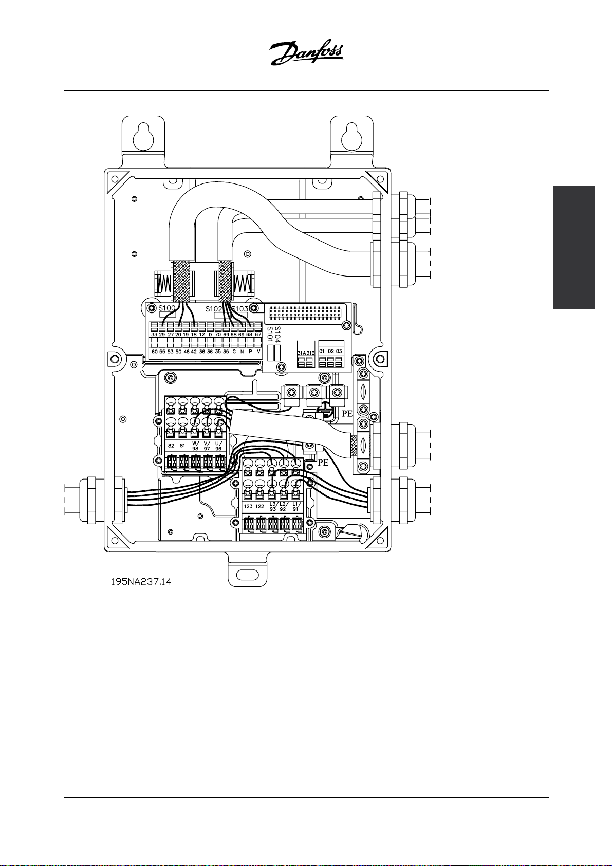
Decentral Solutions
concept
The decentral
Example of power and bus looping
MG.90.F2.22 - VLT is a registered Danfoss trademark
37
Page 38

Decentral Solutions
■Guidelines for selection of cables and fuses in a
power line installation with FCD and DMS products
It is assumed that the installation follows the Low
Voltage Directive as stated in HD 384 and IEC 60364.
This section can’t be used in explosive areas and where
fire hazard exists. In general cable dimension has to
follow IEC 60364-5-523. If the installation is part of a
machinery EN 60204-1 has to be followed. Cables as
mentioned under point 1, 2 and 3 in the figure have
to be protected by an enclosure or conduit.
The following section numbers refer to the figure.
1. The cable shall only be able to carry the maximum
continuous current of the friction brake. By ground
fault non-renewable protective circuit in the FCD
will interrupt the flow of current.
2. If the IP 65 brake resistors recommended by
Danfoss are used the cable will only be exposed
to the continuous current of the brake resistor.
If the brake resistor becomes overheated it will
disconnect itself. If another type or make of
brake resistor, without any power limitation device,
is used, the maximum power must be equal
to the rated power of the motor.
The current in Amps would be: I = 0.77/motor
power, with motor power inserted in HP (kW);
[A=V/W]. The rated motor current comes fairly close
to the current in the cable to the brake resistor.
3. The cables to encoders and thermistors are on
PELV potential. The currents are in mA range
and limited by the FCD or DMS. In order not to
violate the PELV protection of the control terminals
of FCD the thermistor has to have reinforced
insulation according to the PELV demands.
For EMI purposes the cables must have their
own electrical shielding and if possible be kept
separated from power cables.
4. The cable is protected by the current limit function
in the FCD. By ground faults and short circuit of low
impedance the FCD will interrupt the current.
5. The current is limited by the DMS*, and ground and
short circuit protected by the circuit breaker (CB).
6. The current is limited by the downstream FCD and
DMS*. The CB makes the ground and short circuit
protection. The impedance in the leads has to
be so low that the CB disconnects in 5 s by low
impedance ground faults. (TN supply).
7. If installation is on a machine (EN 60204-1) and
the distance between the T connection and the
FCD or DMS* is less than 10 ft (3 m), the cable
can be downsized to the current capacity that
is needed for the down stream FCD.
8. The trip current for the CB upstream must not
be higher than the highest maximal prefuses for
the smallest FCD or DMS downstream.
See section Fuses for DMS coordination class.
For EMC purposes cable # 2, 3 & 4 has to be
shielded or placed in metal conduits.
* only extended versions
38
MG.90.F2.22 - VLT is a registered Danfoss trademark
Page 39
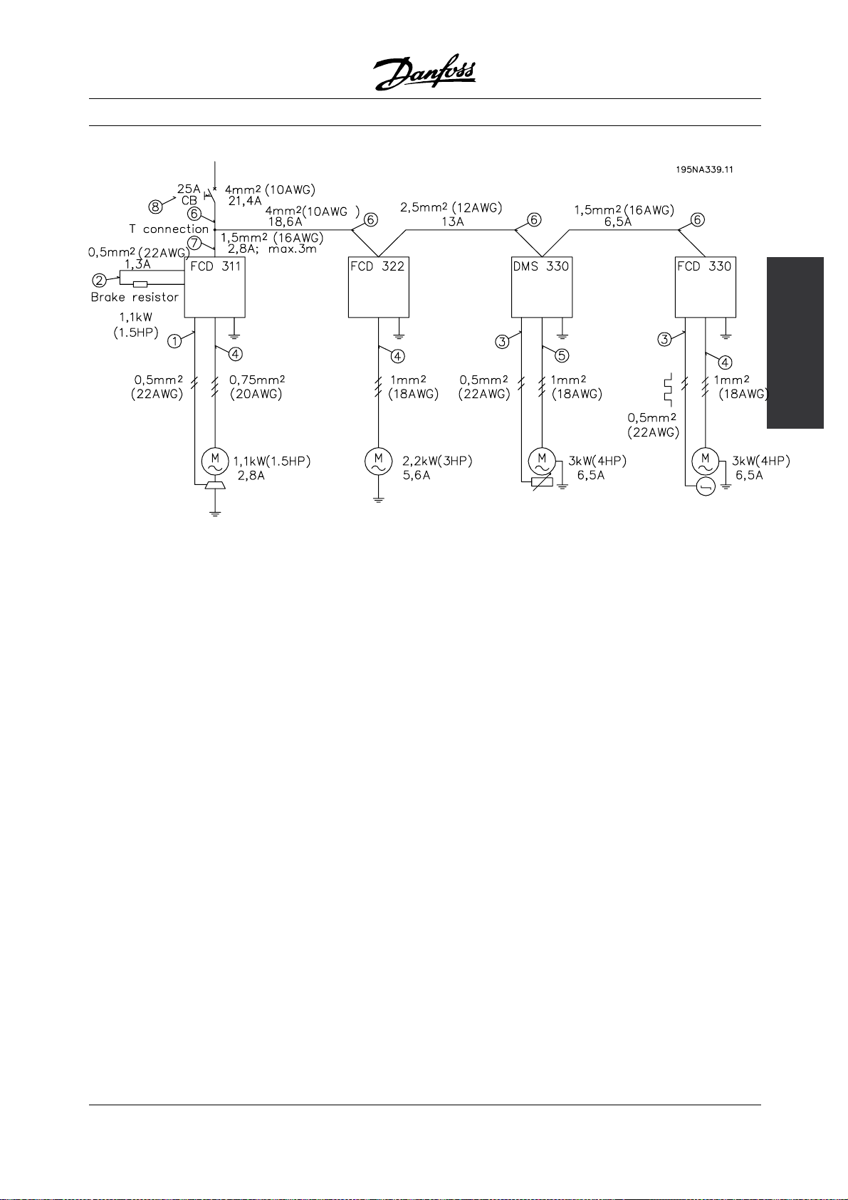
Decentral Solutions
concept
The decentral
Example of decentral cable dimensioning
MG.90.F2.22 - VLT is a registered Danfoss trademark
39
Page 40

Decentral Solutions
■Service
Breakdown of Danfoss drives or geared motors only
occur under exceptional circumstances. As downtime
represents lack of production, failures must be located
and defective components replaced quickly.
Danfoss’ decentralized products place great
emphasis on addressing these issues. This chapter
also describes measures taken to make Danfoss
decentralized products superior in a service situation.
For detailed information on specific service issues
please consult relevant literature.
Centralized adjustable frequency drives from Danfoss
have pluggable connections to facilitate service using
fast and faultless replacement. The same concept is
used and improved for the decentralized drives.
Plug-and-drive
All the advanced and reliable electronics needed
to ensure your motors act smoothly, responsively
and economically at each command are hidden
inside the box lid and plug into connectors when
mounted onto the bottom section. The bottom section
contains maintenance-free Cage Clamp connectors
and looping facilities for power and fieldbus cables
well protected against dust, hosing and cleaning
agents. Once installed, commissioning and upgrading
can be performed in no time simply by plugging in
another control lid. See the illustration.
to fail. In case of a failure in the electronic part,
just remove the six screws, unplug the electronic
part and plug in a new one.
You only need standard installation material like cable
glands, cables, etc., to commission and service a
Danfoss decentralized drive. Special equipment like
hybrid cables not likely to be held in stock by a standard
supplier of electric installation components is needed.
This provides high flexibility and maximum uptime.
Product concept
Since the installation box only contains plugs,
connectors and low density pcb’s, it is not likely
40
MG.90.F2.22 - VLT is a registered Danfoss trademark
Page 41

Decentral Solutions
DMS 300 Series
195NA357.10
300
Introduction, DMS
MG.90.F2.22 - VLT is a registered Danfoss trademark
41
Page 42
■Operating instructions
DMS Version no.02
These operating instructions can be used for all
DMS 300 units with version no. 02.
The version no. can be identified from the product
serial number. The 5th and 6th digit from left
pertain to the version no.
Thus serial number xxxx-02-xxx indicates
version no. 02.
■Symbols used in this manual
When reading this manual you will come across
different symbols that require special attention.
The symbols used are the following:
NOTE
Indicates something to be noted by the reader
Indicates a general warning
Decentral Solutions
■Safety regulations
1. The DMS must be disconnected from the AC
line if repair work is to be carried out.
2. The [COASTING STOP INVERSE] command
applied to the DMS does not disconnect the
equipment from the mains and thus is not to
be used as a safety switch.
It is the responsibility of the user or the
person installing the DMS to provide proper
grounding and branch circuit protection in
accordance with national and local regulations.
■Warning against unintended start
1. The motor can be brought to a stop by means
of digital commands, bus commands or a local
stop, while the DMS is connected to the AC line. If
personal safety considerations make it necessary
to ensure that no unintended start occurs,
stop functions are not sufficient .
2. A motor that has been stopped may start if faults
occur in the electronics of the DMS.
these
Indicates a high voltage warning
■General warning
The DMS contains dangerous voltages
when connected to line voltage. Only a
competent electrician should carry out the
electrical installation. Improper installation of the motor
or the DMS may cause equipment failure, serious
injury or death. Follow this manual as well as national
and local rules and safety regulations.
■Avoiding DMS damage
Please read and follow all instructions in this manual.
Electrostatic Precaution; Electrostatic
discharge (ESD). Many electronic
components are sensitive to static
electricity. Voltages so low that they cannot be
felt, seen or heard, can reduce the life, affec
performance, or completely destroy sensitive
electronic components. When performing service,
proper ESD equipment should be used to prev
possible damage from occurring.
t
ent
42
MG.90.F2.22 - VLT is a registered Danfoss trademark
Page 43
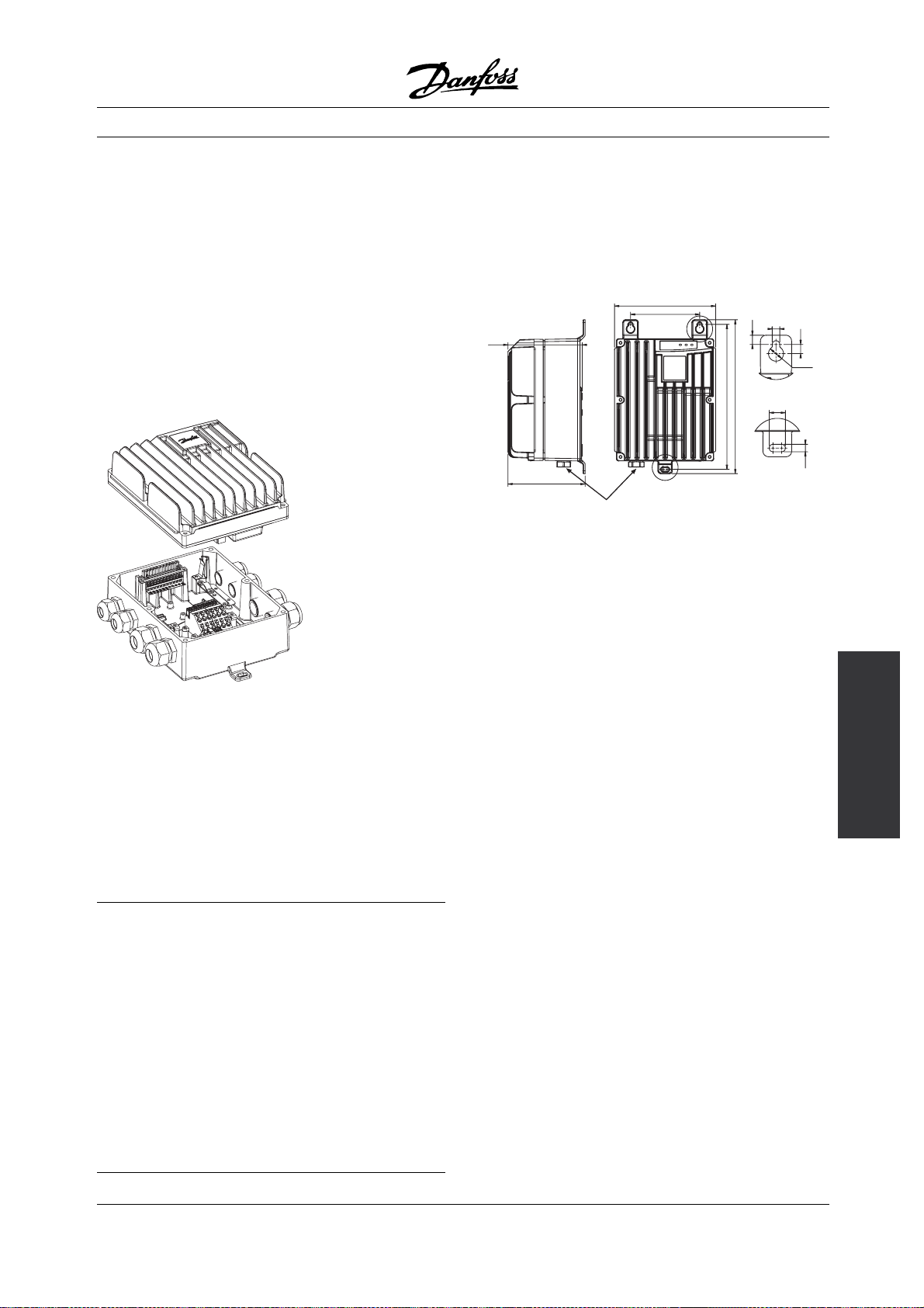
Decentral Solutions
■Description
The Danfoss DMS is an advanced electronic motor
starting system. It performs six main functions;
1. Start control, including soft start.
2. Stop control, including soft stop (extended
stop time).
3. Thermistor motor protection
4. Electronic motor protection (optional).
5. Electromechanical brake control (optional)
6. Monitoring & system interface.
■General layout
177ha010.10
■Construction
The DMS unit is made of two separable parts:
1. Installation box, which is the bottom half. The
installation box has all the mounting arrangement,
cable entries, and grounding studs.
2. Electronics Module, which is the top half.
The electronics module contains all the
circuitry of the DMS.
■Wall mounting
For best cooling, the DMS unit should be mounted
vertically. If needed, horizontal mounting is allowable.
For installing, use the three eye-holes provided.
Use the nylon washers provided to avoid
scratching the protective paint.
mm (inches)
129 (5.10)
134 (5.28)
Ground plug for type T73
2
16 mm
(0.63 in2) max.
176 (6.93)
120 (4.73)
8.0 (0.32)
252 (10.00)
267 (10.50)
Dimension drawing - DMS Wall mount version
■Motor mounting
1. Remove the cover of motor terminal box.
2. In the DMS Installation box, knock out 4 screw
holes to match the motor terminal box.
Two hole-patterns (4 holes each) have been
provided to suit Danfoss Bauer geared motors,
depending on the power size of the motor.
For different motors use the outer holes and the
adaption plate [Order no. 175N2115]
3. In the DMS Installation box, knockout the motor
cable gland (1 of 1.2 in (30 mm diameter)) for the
power connection to motor terminals.
4. Mount the DMS Installation Box direct on
the motor terminal box.
6.5 (0.26)
14.0 (0.55)
177ha002.20
8.0 (0.32)
ø 13.0 (0.51)
6.5 (0.26)
300
DMS
Mechanical details,
■Tools required
The DMS unit does not require any special
tools for installation.
All the power & control connections are snap-on,
spring-loaded type.
The following set of tools is adequate for
installing the DMS units:
- Screw Drivers, general (or T20 Torxslot)
- Spanners - 28 AF and 24 AF
- Center-punch for motor-mounted versions, if
not already mounted on a motor
MG.90.F2.22 - VLT is a registered Danfoss trademark
43
Page 44

Decentral Solutions
98.0
60.0
60.0
98.0
177ha008.10
Dimension drawing - DMS Motor mount version
NOTE
Do not mount in direct sunlight or near
heat radiating elements.
FLC
100%
98%
96%
94%
92%
177ha022.20
1000 (3300)
Altitude from Mean Sea Level
Derating curve for altitude
2000 (6600) 3000 (10000)
40 (104)
38 (100)
36 (97)
34 (93)
m (ft)
F) at 100% FLC
o
C (
o
Max. ambient temperature
■Ventilation
DMS cooling is by means of air circulation.
Consequently, the air needs to be able to move
freely above and below the soft starter.
If installing the DMS in a switchboard or other
enclosure, ensure there is sufficient airflow through
the enclosure to limit heat rise in the enclosure to
maintain the internal enclosure temperature at or
below 104 deg. F. (40 deg. C.) (Heat loss of DMS at
rated current is 0.025 HP (18 watts) approx.).
FLC
100%
90%
80%
70%
177ha021.10
40 (140) 50 (122) 60 (140)
Temperature
°C (°F)
Derating curve for temperature
44
MG.90.F2.22 - VLT is a registered Danfoss trademark
Page 45

■Power Wiring
Connect the Supply voltage to the DMS input
terminals 1/L1, 3/L2 & 5/L3.The terminals in the
Extended versions of the DMS allow two cables
to loop the power line as shown.
Use of screw driver to open the connector clamp
177ha011.10
Decentral Solutions
For ST & SB versions, provide strain relief for power
and control cables by using the cable support
provided in the DMS unit, as shown.
■Power factor correction
3-phase Mains from
power-bus/
previous unit
3-phase Mains to
next unit
e77ha013.eps
Looping the power line - 3-phase AC lines
Connect the Motor terminals to the DMS output
terminals 2/T1, 4/T2 & 6/T3. Take care of the phase
sequence to have the correct direction of rotation.
The terminals in the Extended versions of the
DMS allow two cables to connect two motors
in parallel to one DMS.
Maximum cross section: 0.15 in sq. (10 AWG)
If a DMS is used with static power factor
correction it must be connected to the
supply side of the DMS.
Connecting power factor correction
capacitors to the output of the DMS will result
in damage to the DMS.
■Control Wiring
Complete the Control wiring as shown in the
Electrical Schematic diagram.
Use of a screw driver to open the connector clamp
for control terminals [Press to open the clamp]
Electrical
connections, DMS 300
177ha012.10
Rev310103
MG.90.F2.22 - VLT is a registered Danfoss trademark
Connect Control Supply / AS-i Interface at
the terminals provided.
45
Page 46

Contacts used for controlling these inputs should be
low voltage, low current rated (Gold flash or similar)
2
Maximum cross section: 0.1 in
U
se cables complying with local regulations.
(12 AWG)
Decentral Solutions
46
MG.90.F2.22 - VLT is a registered Danfoss trademark
Page 47

Decentral Solutions
■Motor thermistors
If the motor is fitted with thermistors these may
be connected directly to the DMS. To connect the
thermistors, first remove the shorting link, and then
connect the thermistors between terminals 31A & 31B.
Use double-isolated thermistors to
retain PELV.
■Serial communication
The DMS can be equipped with either AS-i or
Profibus communication capabilities.
The AS-i and Profibus interfaces are optional.
The AS-i Fieldbus is connected at terminals 125 & 126.
The details of the Profibus connectivity are given
at the end of the manual.
NOTE
Communications and control cabling should
not be located within 1 ft (300 mm) of power
cabling. Where this cannot be avoided
consideration should be given to providing magnetic
shielding to reduce induced common mode voltages,
for example, by laying the communication and
control cables in a separate conduit.
■Galvonic isolation (PELV)
All control terminals, and terminals for serial
communication are safely isolated from the
AC lines potential, i.e. they comply with the
PELV requirements of EN/ IEC 60947-1. PELV isolation
of the control card is guaranteed provided there is
max. 300 VAC between phase and ground.
■Grounding
Ensure that the DMS unit is grounded
properly. Use the chassis ground studs
provided for the purpose (4 of size M4).
For type T73 units, an external ground plug
(size M8) is provided to facilitate grounding.
To retain the IP rating of DMS, remember
to close all the unutilized cable entries
using the gland plugs (bungs) provided
loose with the DMS unit. In units with external plugs,
all plugs must be correctly mounted.
■High voltage warning
The voltage of the DMS is dangerous
whenever the equipment is connected to
the AC line. Ensure the DMS is correctly
connected and that all safety measures have been
taken before switching on the supply.
Electrical
connections, DMS 300
MG.90.F2.22 - VLT is a registered Danfoss trademark
47
Page 48

■Electrical Schematic
Decentral Solutions
48
MG.90.F2.22 - VLT is a registered Danfoss trademark
Page 49

■Adjustment/ Settings
DMS adjustments are made using the DIP switch
adjustment panel located on the underside of
the Electronics module.
Decentral Solutions
Section Switch no.
1 Off
177ha007b.10
2 Off
1
2
3
4
5
6
A
3 Off
4
5 Off
6
1
2
3
4
5
6
B
1 Not used
2 3.2A Off
3 1.6A Off
4 0.8A Off
5 0.4A Off
6
OFF
ON
Note: Settings marked grey are applicable
only in Extended versions.
Description Value Factory setting
Start/ stop
profile setting
Selection of
ramp times
Profile no.0
and start
voltage. See
table below.
Off
Trip clas s
selection
Full load
See table
below Off
Trip cla ss 5
Off
FLC = 0.1A
current
setting (note:
0.1Amps is
always added
internally)
0.2A
See table
Off
below
■Start/ stop profile setting
Choose the required Start/ Stop profile which is most
suited to the application. Use DIP switches A1-A4 to set
the start/stop profile. Some examples are shown below.
300
Setting up DMS
MG.90.F2.22 - VLT is a registered Danfoss trademark
49
Page 50
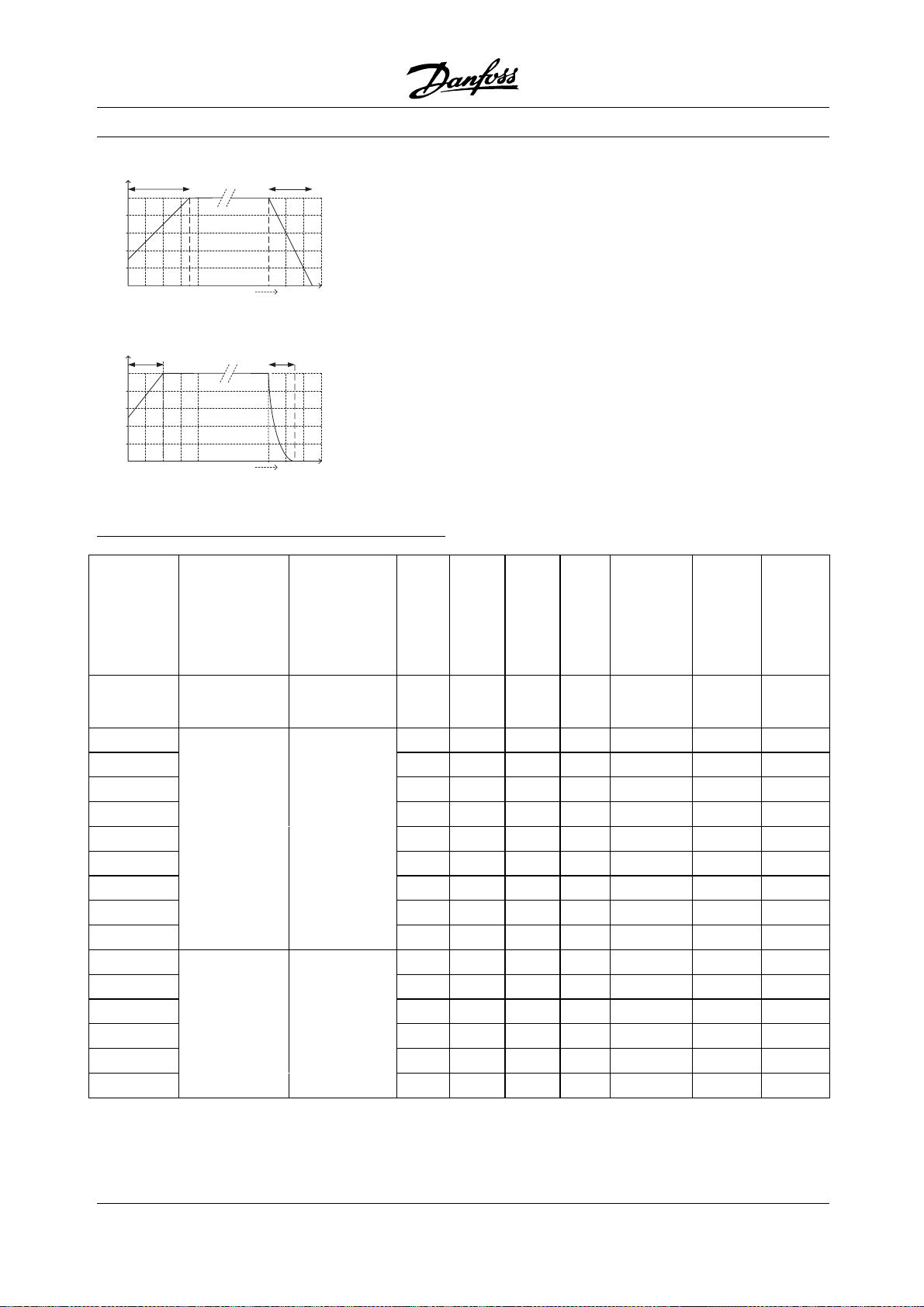
Decentral Solutions
7 Sec.
Start ramp Stop ramp
100%
80%
60%
Motor voltage %
40%
20%
4
8
4
8
4 Sec.
Start ramp
100%
80%
60%
Motor voltage %
40%
20%
177ha025.10
26
Start-stop Profile no: 14
26
Start-stop Profile no: 7
Start/stop
Profile
Performance
Run
Time, sec.
[DIP Switch settings
A1,A2,A3:ON; A4:OFF]
Run
Time, sec.
[DIP Switch settings
A1:OFF; A2,A3,A4:ON]
Start
5 Sec.
Coast to stop
Stop
Performance1(A1)
■Start/ stop profile setting table:
Initial
Voltage
(%)
2(A2) 3(A3)
4
(A4)
Start
Ramp
Time
(sec) #
Stop
Ramp
time
(sec) #
0
Equivalent to
DOL
Coast to stop Off Off Off Off 80 0.25 *
1 Fastest
2 |
3 |
4 |
5 |
Coast to stop
6 |
7
8
|
|
9 Slowest
10 Fastest Fastest
11 | |
12 | |
13 | |
14 | |
15 Slowest Slowest
Off Off Off On 80 0.5 *
Off Off On Off 60 0.75 *
Off Off On On 60 1.5 *
Off On Off Off 60 1.0 *
Off On Off On 50 2 *
Off On On Off 40 3 *
Off On On On 50 4 *
On Off Off Off 60 6 *
On Off Off On 60 8 *
On Off On Off 60 2 1
On Of
f
On On 50 3 2
On On Off Off 40 4 3
On On Off On 40 5 3
On On On Off 30 7 5
On On On On 30 9 7
50
MG.90.F2.22 - VLT is a registered Danfoss trademark
Page 51
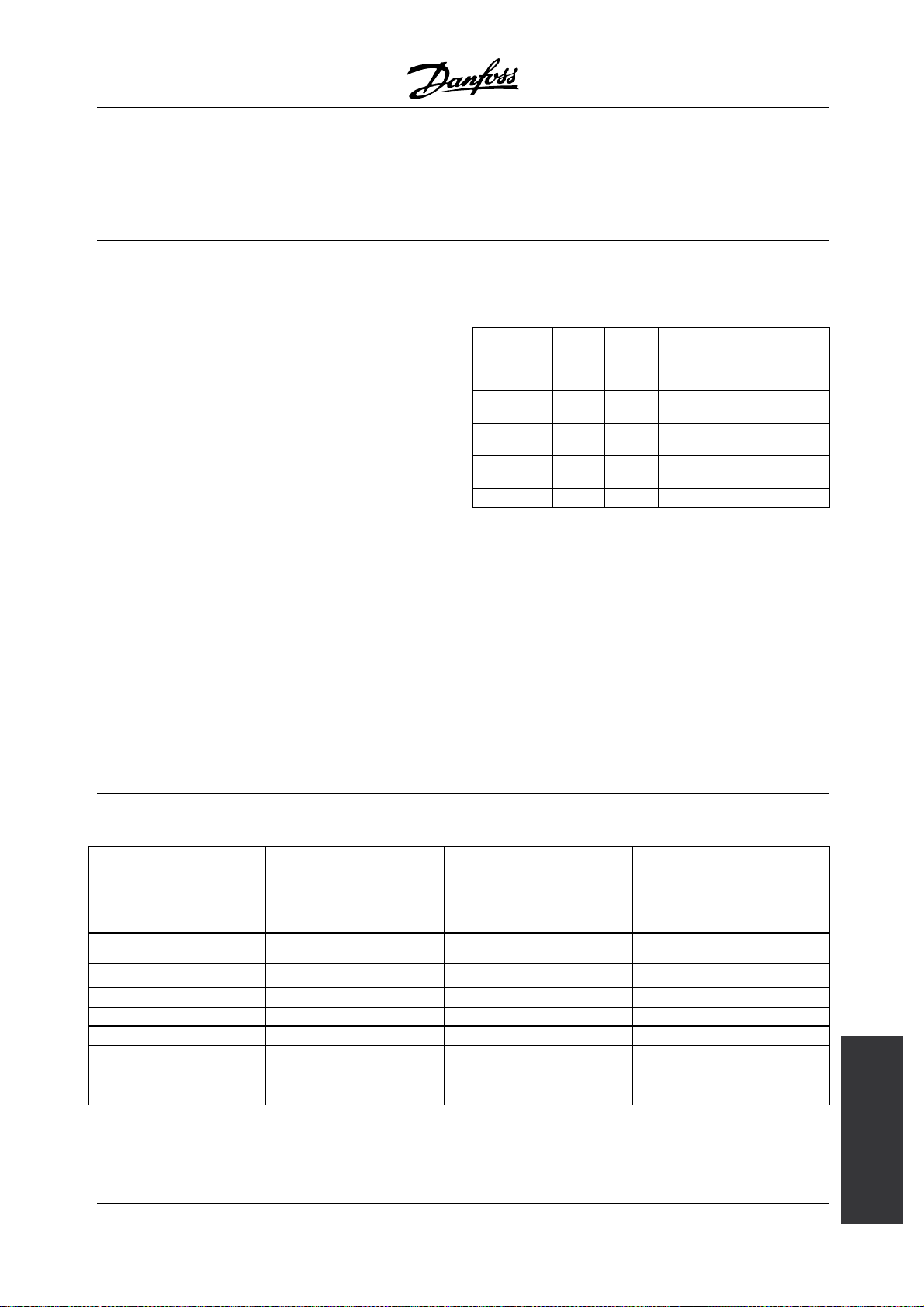
Decentral Solutions
Note: * indicates Stop Ramp time is not controlled
byDMS.Motorwillcoasttostop.
■Trip Class selection:
This setting is applicable only for the Extended
versions of DMS.
The DMS motor overload protection is an advanced
motor thermal model. Motor temperature is
continuously calculated by the microprocessor.
This uses a sophisticated mathematical model
to accurately reflect motor heat generation and
dissipation during all stages of operation, e.g.
Starting, Running, Stopping & Stopped.
Because it operates continuously, the motor thermal
model eliminates the need for protection systems such
as Excess Start Time, Limited Starts per hour etc.
Calibrate the DMS motor thermal model for theTrip
Class of the connected motor. The Motor Trip
Class is defined as the length of time the motor
can sustain Locked Rotor Current. The motor
Trip Class can be found from the motor curves
or data sheet. For example, if a given motor can
withstand Locked Rotor Current for 10 sec, set
Trip Class 10 (or lower) in the DMS.
If in doubt, use "Trip Class 5", which is the Factory
Default setting for this parameter. With this setting,
the DMS will trip & protect the motor if the Locked
Rotor current sustains for more than 5 secs.
# In some applications, actual ramp time on the
motor shaft could differ from the settings.
Use the DIP switches A5-A6 to choose the Trip Class.
■Trip Class selection table :
Trip Cla ss
Time
(sec)
5
(A5)6(A6)
Remarks
5 Off Off Tr ip Clas s 5
10 Off On Trip Cla ss 1 0
20 On Off Trip Class 20
0 On On Motor Protection off
■Full Load Current setting:
This setting is applicable only for the Extended
versions of DMS and refers to the ETR function. It
may not be used for current limitation.
Calibrate the DMS for the connected motor
nameplate Full Load Current (FLC).
Use the five (5) DIP switches B2-B6 to add up to motor
nameplate FLC minus 0.1 Amps. (0.1 Amps is added
internally to the FLC amps. read from the DIP switches)
Please note that switch B1 is not used.
■FLC setting table :
DIP Switch bits Value (Amps)
2(B2) 3.2 On Off
3(B3)
1.6
4(B4) 0.8 On On
5(B5) 0.4 Off On
6(B6) 0.2 On Off
6.3 Amps, when B2-B6
are all On
MG.90.F2.22 - VLT is a registered Danfoss trademark
Example-1 for setting
FLC=4.3 Amps
Off On
0.1+3.2+0+0.8+0+0.2
=4.3
See remark
Example-2 for setting
FLC=2.9 Amps
0.1+0+1.6+0.8+0.4+0
=2.9
See remark
300
Setting up DMS
51
Page 52

Note: 0.1 Amps is added internally to the
value read from DIP switches.
■Completing the installation:
To complete installation, fit the DMS Electronics
module to the DMS Installation box and secure with
the screws provided. Recommended tightening torque
for the screws is between 2.5 and 3 Nm.
Decentral Solutions
52
MG.90.F2.22 - VLT is a registered Danfoss trademark
Page 53

■Operation
Once the DMS has been installed, wired and
programmed according to the instructions,
it can be operated.
Decentral Solutions
■Operation with AS-i Interface
The AS-i switch profile S-7.E is used, having the
following inputs and outputs:
■Powering-up the DMS
PowermaynowbeappliedtotheDMSunit.
The "On" LED should glow when the 24VCD
Control Supply is turned On.
■Starting the motor:
Connect +24VDC to the "Reset/ Coasting
stop inverse input (27).
To start the motor in the Forward direction,
use the Start CW Input (18). To initiate a stop,
open the Start CW Input.
To start the motor in the Reverse direction, use the
Start CCW Input (19).This feature is optional. To
initiate a stop, open the Start CCW Input.
If the direction of rotation is wrong, change any
two of mains or motor phases.
Disconnecting the +24VDC to the "Reset/ Coasting
stop inverse input (27) will disable the DMS and
cause the motor to coast to stop.
NOTE
If both Start CW & Start CCW inputs are
active together, the motor will stop.
• Start CW (DO)
• Start CCW (D1)
• Brake Control (D2)
• Reset (D3)
• Ready output(D0)
• Run Output (D1)
• Fault Output (D2)
The profile codes with the different variants are:
• Profile 7E 1 for Extended
• Profile 7E 3 for Extended with Brake
• Profile 7E 4 for Extended with Brake & Reverse
300
Operation details, DMS
■Brake Release
(For variants with Braking function only variants SB, EB, ER).
When a Start is initiated, the DMS automatically
generates a brake release command. This will release
the brakes before the motor starts running.
The motor brake can also be released without
starting the motor by connecting +24VDC to
the Brake Release input (124).
NOTE
MainssupplytotheDMSisrequiredfor
the operation of Brake Release. The
Electromechanical brake supply is not
short-circuit protected.
MG.90.F2.22 - VLT is a registered Danfoss trademark
53
Page 54

■Description of AS-i profiles used with DMS
Decentral Solutions
Bit Ty pe f or ho st Meaning
D0 output Run forward
D1 output Run reverse
D2 output Brake
D3 output Fault reset
D0 input Ready
D1 input Running
D2 input Fault
D3 input Not used
P0 parameter Not used
Host
level
0
1
0
1
0
1
0
1
0
1
0
1
0
1
0
1
Direct starter
Profile 7E 1
Stop - forward
Start - forward
Not used Not used
Not used
Not reset
Reset
Not ready or fault
Ready
Motor stopped
Motor running
No fault
Fault
Direct starter with
brake
Profile 7E 3
Stop - forward
Start - forward
Motor blocked
Motor free
Not reset
Reset
Not ready or fault
Ready
Motor stopped
Motor running
No fault
Fault
Reverser with brake
Profile 7E 4
Stop - forward
Start - forward
Stop - reverse
Start - reverse
Motor blocked
Not ready or fault
Motor stopped
Motor running
Not used Not used Not used
Motor free
Not reset
Reset
Ready
No fault
Fault
P1 parameter Not used
P2 parameter Not used
P3 parameter Not used
It is possible to operate DMS with both the control
inputs and an AS-i Interface. It will function as follows:
• Start CW: Logically "OR"ed - DMS will Start
if either input is active.
• Start CCW: Logically "OR"ed - DMS will Start
if either input is active.
• Brake: Logically "OR"ed - DMS will generate Brake
release command if either input is active.
• Reset/Coasting stop inverse: Logically "AND"ed.
NOTE
Both inputs must be active for DMS to Start.
If AS-i bus is used for control, the binary
Reset/Coasting stop inverse input must be
held active (i.e. connected to +24 VDC)
Use a standard AS-i addressing device or the AS-i
master to configure the DMS with the designated
slave address on the AS-i network.
Configuring DMS with a Slave address:
54
MG.90.F2.22 - VLT is a registered Danfoss trademark
Page 55

Decentral Solutions
■Fault Procedure
Use the Reset (Reset/ Coasting stop inverse)
input to reset any fault.
The "On" LED (Green), when illuminated, indicates
that the Control supply is on.
The "Bus" LED (Green), when illuminated, indicates
that AS-i bus communication is OK.
■Reading the "Alarm" LED
No. of
Trip Condition Cause & Action
The "Alarm" LED (Red), when illuminated, indicates
that the DMS is in the alarm/ trip state.
The number of Alarm LED flashes indicates the fault/
trip condition. The Alarm LED will flash a certain
number of times, depending on the nature of fault.
flashes
One (1) PowerLossorShortedSCR Check supply voltages. This is a pre-start check.
Two ( 2) Thermal Overload Check FLC setting.
Check the Motor Trip class setting.
Remove the cause of the overload and let the
motor cool before restarting.
Three (3) Motor Thermistor Trip Identify and correct the cause of motor
overheating.
If no thermistors are connected to the DMS,
ensure there is a closed circuit across the motor
thermistor input (terminals 31A & 31B).
Four (4) Phase Loss Check supply for missing phase. This is active
anytime during start.
Five (5) Welded Direction Change Relay Replace unit.
300
Operation details, DMS
MG.90.F2.22 - VLT is a registered Danfoss trademark
55
Page 56

Decentral Solutions
■General Technical Data
Supply (L1, L2, L3, 125, 126, 127, 128):
AC line Supply voltage ........................................................................................ 3 x 380 VAC ~ 480 VAC +/- 10%
AC Line Supply frequency ................................................................................................................. 45HZ ~ 65 Hz
Electronics control voltage .......................................................................... +24VDC (20V to 30V), 150mA nominal
Control Inputs
Start (Terminals 18 & 19) .......................................................................................... Binary, 24 VDC, 8mA approx.
Reset/ Coasting stop inverse(Terminal 27) ........................................................... Binary, 24 VDC, 90mA approx. #
Release Electromechanical Brake (Terminal 124) ..................................................... Binary, 24 VDC, 8mA approx.
The Control inputs are suitable for connection to a d evice with a PNP output stage.
#20mAapprox. forStandradversions(SB&ST)
Outputs
Run Output (Terminal 46) ....................................................................... Binary, PNP output, 24 VDC, 20mA max.
The output is short circuit protected.
Electromechanical Brake Supply output
Electromechanical Brake Supply Output (Terminals 122 & 123) ........................................... 180 VDC, 1.0 A max. *
* The electro-mechanical brake supply output voltage is proportional to the Ac line supply vo
which is 180 VDC f or 400VAC mains, 205 VDC for 460 VAC AC lines.
The output is not short circuit protected.
ltage,
Operating temperature ......... 14 to +140 deg. F (-10 to +60 deg. C.)(above 104 deg. F. (40 deg. C.) with derating)
Relative humidity ........................................................................................................ 5 -90% RH, non-condensing
Weight .............................................................................................................................................. 7.7 lb (3.5 kg)
■Current Ratings (AC53a ratings)
These ratings assume Starting current of 500%
FLC. All ratings are in Amps.
Continuous Ratings (Not bypassed) at 104 deg. F (40 deg C.) Ambient Temperature, < 3000 feet
(1000 m)
Duty Cycle
No. of starts per hour Start Time (sec.)
70% 50% 30%
10 5 8.4 8.7 9.0
50 5 7.9 8.1 8.3
100 5 7.3 7.5 7.6
300 1 7.7 8.0 8.2
For ambient temperature or altitude conditions
beyond t
hose listed contact Danfoss.
56
MG.90.F2.22 - VLT is a registered Danfoss trademark
Page 57

Decentral Solutions
■Ordering type code
The DMS is available in the following variants:
- Standard
-StandardwithBrake
- Extended
- Extended with Brake
- Extended with Brake & Reverse
■Certifications
The DMS 300 has CE, UL, cUL and C-tick
certifications. The details are as under:
CE
Rated insulation voltage ............................................................................................................................ 500 VAC
Rated impulse withstand ........................................................................................... 2.0 kV (1.2/ 50 micro second)
Conducted and radiated frequency emissions ................................................................ Class B as per EN 55011
Electrostatic discharge, 4 kV contact and 8 kV air discharge ................................................ no effect on operation
Radio frequency electromagnetic field, 0.15 MHz to 1.0 GHz ................................................ no effect on operation
Fast transients, 2.0 kV/ 5.0 kHz ............................................................................................ no effect on operation
Surges, 2.0 kV line to earth, 1.0 kV line to line ...................................................................... no effect on operation
Voltage dips and short interruptions ...................................................................................... no effect onoperation
Short circuit tested on 5 kA supply, when protected by semiconductor fuses (Type 2 co-ordination) ................... no
damage to DMS 300, no danger to persons or installation
Short circuit tested on 5 kA supply, when protected by HRC fuses (Type 1 co-ordination) ................................... no
danger to persons or installation, DMS unit may be unsuitable for future use
The Extended varaints are available with integrated
Fieldbus AS-i interface. The extended versions can be
delivered with Profibus interface including 4 additional
M12 plugs for connection of external sensors.
RefertothetableforthePartnumbers
corresponding to the variants.
For example, the part number for a Motor Mount
DMS unit, with Reverse function, and without
Fieldbus connection would be:
DMS330PT4P66ERD0F00T12C0
Specification and
order codes, DMS 300
UL
C-tick
IP66
To maintain certifications, the product shall not be
modified an any way, shall be used only for the specified
purpose, and must be installed according to this manual
and/or any other authorized Danfoss instruction.
■Fuses
The DMS 300 should be used with suitable fusing as
per the co-ordination requirements of the circuit..
Max pre-fuses: DMS 300 meets Type 1 co-ordination
with properly rated HRC fuses.
Use type gG 25A, 415 VAC or equivalent HRC fuses.
MG.90.F2.22 - VLT is a registered Danfoss trademark
Semiconductor fuses are required to meet
UL, C-UL Certification.
Semiconductor fuses listed below are manufactured
by Bussmann and should be ordered directly from
Bussmann or their local supplier.
Bussmann, High Speed fuse, Square body, Size 000,
660 V, 20 Amps rated - Part no: 170 M 1310
or
Bussmann, British style, BS88, Type CT, 690 V,
20 Amps rated - Part no: 20CT
57
Page 58

■Special variants:
o
In addition to the installation boxes described
earlier, DMS units can be offered as variants with
additional functionality and options
Example 1
Variant T73: DMS Extended unit with Profibus
communication option, 4 x M12 sensor plugs
(as described above) plus a special Harting
connector for motor connections.
Picture of DMS Unit with Profibus card, with
4 x M12 connectors for sensors, and Harting
connector for Motor connections
■Motor connection
The motor must be connected by a Han 10E connector
according to the DESINA standard.
Decentral Solutions
Example 2
Variant T22 or T62: DMS Extended unit with
an integrated service switch.
The service switch can either be connected between
the AC line supply & DMS unit, or between DMS
unit and the motor, as shown here.
3-PHASE SUPPLY
(POWER-BUS)
SERVICE SWITCH
1/L1
3/L2
5/L3
DMS Unit
2/T1
4/T2
6/T3
To Motor
Pin
no.
Function
Pin
no.
Function
1 Motor U 6-8 Not connected
2 Motor V 9
3 Motor W 10
Electromechanical
4
Electromechanical
5
brake B
brake A
PE
Motor
thermistor A
Motor
thermistor B
Ground
connection
SERVICE SWITCH
SERVICE SWITCH
177ha024.10
3-PHASE SUPPLY
(POWER-BUS)
To other Decentral controllers
1/L1
3/L2
5/L3
1/L1
3/L2
5/L3
The service switch used for providing isolation to DMS Unit and the mot
1/L1
3/L2
DMS Unit
5/L3
The service switch used for providing isolation to only the motor.
DMS Unit
DMS Unit
2/T1
4/T2
6/T3
2/T1
4/T2
6/T3
SERVICE SWITCH
2/T1
4/T2
6/T3
To Motor
To Motor
To Motor
Examples of connection of Service switch
58
MG.90.F2.22 - VLT is a registered Danfoss trademark
Page 59

■Details of Profibus Connectivity NOTE
When using Profibus interface, the complete
control of the DMS is done by the Profibus. T
DMS control terminals cannot be used.
■Profibus DP Slave 6 E/DC 24 V, 4 A/DC 24 V/1A
spring terminal block 2 x 2 x 0.1 sq.in. (2.5
connection bus connection
sq.mm.)
69: A-Line RxD/TxD-N, green wire 68:B-Line
RxD/TxD-P, red wire
termination switchable, SW2 both on
supply power to the
module
voltage range incl. ripple 20-30VDC
ripple max. 10%
current consumption nom. 90 mA
spring terminal block 2 x 2 x 0.1 sq.in. (2.5
connection
sq.mm.)
201: DC 0 V, 202:DC 24 V
supply power input and
output
voltage range incl. ripple 20-30VDC
spring terminal block 2 x 2 x 0.1 sq.in. (2.5
connection
sq.mm.)
203: DC 0 V, 204:DC 24 V
DC 500 V between bus and electronics
galvonic isolation isolation voltage
DC 2.5kV between module supply and
inputs/ outputs
Bus interface Bus system Profibus DP
module type Slave I/O module
standard DIN 19245
data width in the process image 1 Byte inputs, 1 Byte outputs
fieldbus controller LSPM2
identifier 0409 hex
addressing Node ID: 1-99 set by DIP switch SW3
baud rate up to 12Mbaud, automatic detection
Decentral Solutions
he
Specification and
order codes, DMS 300
MG.90.F2.22 - VLT is a registered Danfoss trademark
59
Page 60
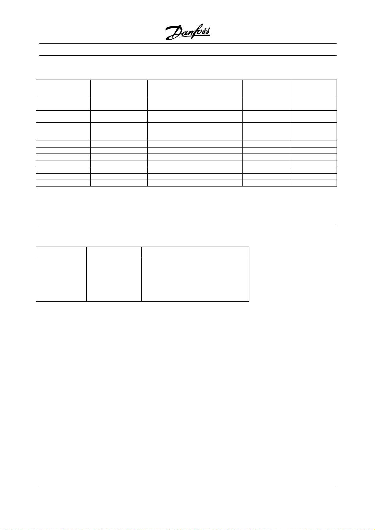
■Tableofbitsincontrolandstatusword
Decentral Solutions
Te rm i na l
connection
Output 1 18 Start CW Bit 0
Output 2 19 Start CCW Bit 1
Output 3 27
0V 125 (203)
+24V 126 (204)
Input 1 M12, I1 Input Bit 0
Input 2 M12, I2 Input Bit 1
Input 3 M12, I3 Input Bit 2
Input 4 M12, I4 Input Bit 3
Input 5 46 Ready Bit 4
The GSD file is available on the internet at
www.danfoss.com/drives
■Profibus connector PCB 4 x M12
inputs number 4xM12femalesocketIP67
connection
Function
Reset/
Coasting stop inverse
M12 female socket
Pin 1: DC 24 V
Pin 2: NC (not connected)
Pin 3: DC 0 V
Pin 4: input
Profibus
control word
Bit 2
Profibus status
word
60
MG.90.F2.22 - VLT is a registered Danfoss trademark
Page 61
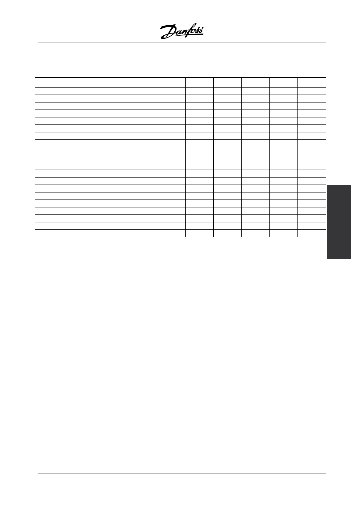
Decentral Solutions
■Profibus address setting: DIP switch SW3
Address decimal DIP 1 DIP 2 DIP 3 DIP 4 DIP 5 DIP 6 DIP 7 DIP 8
x0 1 1 1 1 x x x x
x1 0 1 1 1 x x x x
x2 1 0 1 1 x x x x
x3 0 0 1 1 x x x x
x4 1 1 0 1 x x x x
x5 0 1 0 1 x x x x
x6 1 0 0 1 x x x x
x7 0 0 0 1 x x x x
x8 1 1 1 0 x x x x
x9 0 1 1 0 x x x x
0x x x x x 1 1 1 1
1x x x x x 0 1 1 1
2x x x x x 1 0 1 1
3x x x x x 0 0 1 1
4x x x x x 1 1 0 1
5x x x x x 0 1 0 1
6x x x x x 1 0 0 1
7x x x x x 0 0 0 1
8x x x x x 1 1 1 0
9x x x x x 0 1 1 0
The address 00 is not allowed. Also all positions
not listed in the table are not allowed. In those
cases address 126dec is used.
Specification and
order codes, DMS 300
MG.90.F2.22 - VLT is a registered Danfoss trademark
61
Page 62

Decentral Solutions
FCD 300 Series
Design guide
Software version: 1.4x
This design guide can be used for all FCD 300 Series frequency converters with software version 1.4x.
The software version number can be seen from parameter
640 Software version no.
195NA193.11
NOTE
This symbol indicates something that should
be noted by the reader.
Indicates a general warning.
This symbol indicates a warning of
high voltage.
62
MG.90.F2.22 - VLT is a registered Danfoss trademark
Page 63

Decentral Solutions
■High voltage warning
The voltage of the adjustable frequency
drive is dangerous whenever the drive is
connected to electrical current. Incorrect
fitting of the motor or adjustable frequency drive may
cause damage to the equipment, serious injury or
death. Consequently, it is essential to comply with
the instructions in this manual as well as local and
national rules and safety regulations.
■These rules concern your safety
1. The variable frequency drive must be disconnected
from the AC supply if repair work is to be
carried out. Check that the electrical supply
has been disconnected and that the prescribed
time has passed before removing the inverter
part from the installation
2. The [STOP/RESET] key on the optional control
panel does not disconnect the equipment from AC
supply and is thus not to be used as a safety switch.
3. The unit must be properly connected to the
ground, the user must be protected against
the supply voltage and the motor must be
protected against overloading pursuant to prevailing
national and local regulations.
4. The ground leakage currents are higher than 3.5 mA.
5. Protection against motor overload is not included
in the factory setting. If this function is required,
set parameter 128 Motor thermal protection to
data value ETR trip or data value ETR warning.For
the North American market: The ETR functions
provide overload protection of the motor, class
20, in accordance with NEC.
■Warning against unintended start
1. The motor can be brought to a stop by means of
digital commands, bus commands, references
or a local stop, while the variable frequency
drive is connected to AC line. If personal safety
considerations make it necessary to ensure
that no unintended start occurs, these stop
functions are not sufficient.
2. While parameters are being changed, the motor may
start. Consequently, the stop key [STOP/RESET] on
the optional control panel must always be activated,
following which data can be modified.
3. A motor that has been stopped may start if faults
occur in the electronics of the variable frequency
drive, or if a temporary overload or a fault in the
supply AC line or the motor connection ceases.
Warning:
It can be extremely dangerous to touch the electrical parts
even when the AC line supply has been disconnected.
For FCD 300: wait at least 4 minutes.
195NA194.10
300
Introduction to FCD
MG.90.F2.22 - VLT is a registered Danfoss trademark
63
Page 64

Decentral Solutions
■Technology
■Control principle
A variable frequency drive rectifies AC voltage
from the AC line supply into DC voltage, following
which it changes this voltage to an AC voltage
with variable amplitude and frequency.
The motor thus receives a variable voltage and
frequency, which enables infinitely variable speed
control of three-phase, standard AC motors.
1. AC line voltage
3 x 380 - 480 V AC, 50 / 60 Hz.
. Rectifier
2
Three-phase rectifier bridge which rectifies AC
voltage into DC voltage.
the DC voltage is converted into variable AC
voltage with a variable frequency.
3
. Intermediate circuit
DC voltage √2 x mains voltage [V].
. Intermediate circuit coils
4
Evens out the intermediate circuit current and limits
the load on AC lines and components (electrical
transformer, cables, fuses and contactors).
5
. Intermediate circuit capacitor
Evens out the intermediate circuit voltage.
6
. Inverter
Converts DC voltage into a variable AC voltage
with a variable frequency.
7
. Motor voltage
Variable AC voltage depending on supply voltage.
Variable frequency: 0.2 - 132 / 1 - 1000 Hz.
. Control card
8
Here is the computer that controls the inverter
which generates the pulse pattern by which
64
MG.90.F2.22 - VLT is a registered Danfoss trademark
Page 65

■The decentral concept
The FCD 300 Adjustable speed drive is designed
for decentral mounting, e.g. in the food and
beverage industry, in the automotive industry, or
for other material handling applications.
With the FCD 300 it is possible to utilize the cost saving
potential by placing the power electronics decentrally,
and thus make the central panels obsolete saving cost,
space and effort for installation and wiring.
Theunitisflexibleinitsmountingoptionsforas
well stand-alone mounting and motor-mounting. It
is also possible to have the unit pre-mounted on
a Danfoss Bauer geared motor (3 in one solution).
Thebasicdesignwithaplugableelectronicpartand
a flexible and "spacious" wiring box is extremely
service-friendly and easy to change electronics
without the need for unwiring.
Decentral Solutions
It is easy for the user to program the required functions
on the control panel or via serial communication.
■AC input protection
The FCD 300 Series is protected against the transients
that may occur on the AC line, such as coupling
with a phase compensation system or transients
from blown fuses or lightning strikes.
Rated motor voltage and full torque can be maintained
down to approx. 10% undervoltage in the mains supply.
As all 400 V units in the FCD 300 Series have
intermediate circuit coils, there is only a low amount
of harmonic electrical supply interference. This gives
a good power factor (lower peak current), which
reduces the load on the electrical installation.
The FCD 300 is a part of the VLT variable frequency drive
family, which means similar funcionality, programming,
and operating as the other family members.
■FCD 300 control principle
A variable frequency drive is an electronic unit
which is able to infinitely variably control the rpm
of an AC motor. The variable frequency converter
governs the motor speed by converting the regular
voltage and frequency from AC line, e.g. 400 V /
50 Hz, into variable magnitudes. Today the variable
frequency drive-controlled AC motor is a natural
part of all types of automated plants.
The FCD 300 Series has an inverter control system
called VVC (Voltage Vector Control). VVC controls an
induction motor by energizing with a variable frequency
and a voltage suitable for it. If the motor load changes,
so does its energizing and speed. That is why the
motor current is measured on an ongoing basis,
and a motor model is used to calculate the actual
voltage requirement and slip of the motor.
■Programmable inputs and outputs in four Setups
In the FCD 300 Series it is possible to program the
different control inputs and signal outputs and to select
four different user-defined Setups for most parameters.
■Variable frequency drive protection
The current measurement in the intermediate circuit
constitutes perfect protection of the FCD 300
Series in case there is a short-circuit or a ground
fault on the motor connection.
Constant monitoring of the intermediate circuit
current allows switching on the motor output,
e.g. by means of a contactor.
Efficient monitoring of the electrical supply means
that the unit will stop in the case of a phase drop-out
(if the load exceeds approx. 50%). In this way,
inverter and the capacitors in the intermediate circuit
are not overloaded, which would dramatically reduce
the service life of the variable frequency d
The FCD 300 Series offers temperature protection
as standard. If there is a thermal overload, this
function cuts out the inverter.
■Reliable galvonic isolation
In the FCD 300 all digital inputs/outputs, analog
inputs/outputs and the terminals for serial
communication are supplied from o
with circuits that comply with PELV requirements.
PELV is also complied with in relation to relay
terminals at max. 250 V, so that
connected to AC line potential.
they can be
rive.
r in connection
300
the
Introduction to FCD
MG.90.F2.22 - VLT is a registered Danfoss trademark
65
Page 66

See section Galvonic Isolation (PELV) for further details.
■Advanced motor protection
The FCD 300 Series has integral electronic
motor protection.
The variable frequency drive calculates the motor
temperature on the basis of current, frequency and time.
As opposed to traditional, bimetallic protection,
electronic protection takes account of reduced cooling
at low frequencies because of reduced fan speed
(motors with internal fan). This function cannot protect
the individual motors when motors are connected in
parallel. Thermal motor protection can be compared
to a protective motor switch, CTI.
To give the motor maximum protection against
overheating when it is covered or blocked, or if the fan
should fail, you can install a thermistor and connect it
to the variable frequency drive’s thermistor input (Digital
input), see parameter 128 Thermal motor protection.
Decentral Solutions
NOTE
This function cannot protect the individual
motors in the case of motors linked in parallel.
66
MG.90.F2.22 - VLT is a registered Danfoss trademark
Page 67

Decentral Solutions
■CE labelling
What is CE labelling?
The purpose of CE labelling is to avoid technical
obstacles to trade within EFTA and the EU. The
EU has introduced the CE label as a simple way of
showing whether a product complies with the relevant
EU directives. The CE label says nothing about the
specifications or quality of the product. Variable
frequency drives are regulated by three EU directives:
The machinery directive (98/37/EEC)
All machines with critical moving parts are covered
by the machinery directive, which came into force on
January 1, 1995. Since a variable frequency drive is
largely electrical, it does not fall under the machinery
directive. However, if a variable frequency drive is
supplied for use in a machine, we provide information on
safety aspects relating to the variable frequency drive.
We do this by means of a manufacturer’s declaration.
The low-voltage directive (73/23/EEC)
Variable frequency drives must be CE-labelled in
accordance with the low-voltage directive, which came
into force on January 1, 1997. The directive applies to
all electrical equipment and appliances used in the 50 1000 Volt AC and the 75 - 1500 Volt DC voltage ranges.
Danfoss CE labels in accordance with the directive and
issues a declaration of conformity upon request.
The EMC directive (89/336/EEC)
EMC is short for electromagnetic compatibility. The
presence of electromagnetic compatibility means
that the mutual interference between differen
t
components/appliances is so small that the functioning
of the appliances is not affected.
The EMC directive came into force on 1 January 1
Danfoss CE labels in accordance with the directive and
issues a declaration of conformity upon request. In
order that EMC-correct installation can be
carried out,
this manual gives detailed instructions for installation. In
addition, we specify the standards which our different
products comply with. We offer the filte
rs that can be
seen from the specifications and provide other types of
assistance to ensure the optimum EMC result.
In the great majority of cases, the variable frequency
drive is used by professionals of the trade as a complex
component forming part of a larger appliance, system
or installation. It must be noted that the responsibility
for the final EMC properties of the appliance, system
or installation rests with the installer.
996.
■ATEX
What is ATEX?
Directive 94/9/EC is valid in the European Union (EU)
with the purpose of creating unified standards for
equipment and protective systems intended for use in
potentially explosive atmospheres. The directive was
valid from July 2003, and all equipment installed and
built into potentially explosive areas in EU after this date,
must comply with this directive. The directive and its
derivatives are often referred to as the ATEX-directive.
ATEX is an acronym for ATmosphere Explosible.
It has been found practical to classify hazardous
areas into zones according to the likelihood of an
explosive gas/dust atmosphere being present (see IEC
79-10). Such classification allows appropriate types
of protection to be specified for each zone.
Motors supplied at variable frequency and voltage
When electrical motors are to be installed in areas
where dangerous concentrations and quantities of
flammable gases, vapors, mists, ignitable fibers or dust
may be present in the atmosphere, protective measures
are applied to reduce the likelihood of explosion due to
ignition by arcs, sparks or hot surfaces, produced either
in normal operation or under specified fault conditions.
Motors supplied at varying frequency and
voltage require either:
• Means (or equipment) for direct temperature control
by embedded temperature sensors specifi
ed in the
motor documentation or other effective measures
for limiting the surface temperature of the motor
housing. The action of the protective d
evice shall
be to cause the motor to be disconnected. The
motor and adjustable frequency drive combination
does not need to be tested together,
or
• The motor must have been type-tested for this
duty as a unit in association with the adjustable
frequency drive specified in the d
escriptive
documents according to IEC 79-0 and with
the protective device provided.
FCD 300 and ATEX
The following variants of the FCD 300 can be installed
directly in Group II, Category 3, and Zone 22 areas:
®
VLT
Decentral FCD3xx-P-T4-P66-xx-R1-
Dx-Fxx-T11-Cx
®
VLT
Decentral FCD3xx-P-
T4-P66-xx-R1-
Dx-Fxx-T12-Cx
300
Introduction to FCD
MG.90.F2.22 - VLT is a registered Danfoss trademark
67
Page 68

Decentral Solutions
VLT®Decentral FCD3xx-P-T4-P66-xx-R1Dx-Fxx-T51-Cx
®
Decentral FCD3xx-P-T4-P66-xx-R1-
VLT
Dx-Fxx-T52-Cx
Group II, Category 3, and Zone 22 areas
are characterised by:
• Surface installations
• Explosive atmosphere is unlikely to occur or,
if it does, is likely to only be of short duration
and not in normal duty
• The explosive media is dust
The maximum surface temperature of the FCD 300
during worst-case normal duty is limited to 275ºF
(135°C). This temperature must be lower than the
ignition temperature of the present dust.
The installer must define the zone, category and
dust ignition temperature of the environment
where the FCD 300 is installed.
ATEX correct installation
The following issues must be taken into account when
installing the FCD 300 in ATEX zone 22 environments:
must only be carried out by personnel that are
trained and familiar with the concept of protection.
For a declaration of conformity, please consult
your local Danfoss representative.
• Motor must be designed, tested and certified by the
motor manufacturer for variable speed application
• Motor must be designed for Zone 22 operation.
I.e. with type of protection "tD" acc. to
EN61241-0 and -1 or EN50281-1-1.
• Motor must be provided with thermistor protectio
n.
The thermistor protection must either be connected
to an external thermistor relay, with EC Type
Examination Certificate or compatible with t
he
FCD 300 thermistor input.
If the FCD 300 thermistor protection is used,
the thermistor must be wired to terminals
31a and 31b, and thermistor trip activated by
programming parameter 128 to thermistor trip [2].
See parameter 128 for further detai
ls.
• Cable entries must be chosen for the enclosure
protection to be maintained. It must also be
ensured that the cable entries com
ply with the
requirements for clamping force and mechanical
strengths as described in EN 50014:2000.
• The FCD must be installed with app
ropriate ground
connecting according to local/national regulations.
• The installation, inspection and maintenance of
electrical apparatus for use in
combustible dust,
68
MG.90.F2.22 - VLT is a registered Danfoss trademark
Page 69

■Mechanical dimensions, FCD, motor mounting
■Mechanical dimensions, stand-alone mounting
Decentral Solutions
Mechanical
dimensions in in
FCD 303-
315
FCD 322-
335
(mm)
A 7.56 (192) 10.2 (258)
A1 5.24 (133) 6.69 (170)
B 9.61 (244) 11.8 (300)
B1 11.8 (300) 14.4 (367)
B2 11.2 (284) 13.6 (346)
C 5.59 (142) 5.94 (151)
C1 5.71 (145) 6.06 (154)
Cable Gland sizes M16, M20, M25 x 0.06 in
(1.5 mm)
Space for cable inlets and service switch handle
4-6 in (100-150 mm)
■Spacing for mechanical installation
All units require a minimum of 4 in (100 mm) of air from
other components above and below the enclosure.
300
Installation, FCD
MG.90.F2.22 - VLT is a registered Danfoss trademark
69
Page 70

Decentral Solutions
■Mechanical Installation
Please pay attention to the requirements
that apply to integration and remote
mounting. These must be complied
with to avoid serious injury or damage, especially
when installing large units.
The FCD 300 consists of two parts: The installation
part and the electronics part.
The two parts must be separated, and the installation
part is to be mounted first. After wiring, the electronics
is to be fixed to the installation part by the attached
6 screws. For compressing the gasket the screws
must be tightened with 2.5-3 Nm.
NOTE
Donotswitchonthepowerbeforethe
6 screws are tightened.
The FCD 300 can be applied as following:
- Stand alone mounted close to the motor
- Motor mounted
or might be delivered pre mounted on a Danfoss Bauer
(geared) motor. Please contact the Danfoss Bauer
sales organization for further information.
The adjustable frequency drive is cooled by means
of air circulation. For the unit to be able to release
its cooling air, the minimum free distance above and
below the unit must be m
protect the unit from overheating, it must be ensured
that the ambient temperature does not rise above the
max. temperature stated for the adjustable frequency
drive and that the 24-hour average temperature is not
exceeded. The max. temperature and 24-hour average
can be seen in General technical data. If the ambient
temperature is higher, derating of the adjustable
frequency drive is to be carried out. See Derating for
ambient temperature. Please note that the service life
of the adjustable frequency drive will be reduced if
derating for ambient temperature is not considered.
inimum 4 in. (100 mm).To
the box and the mounting surface. Use the three
supplied washers to protect the paint.
Bolts must be M6 for the FCD 303 - 315 and
M8 for FCD 322 - 335.
See Dimensional Drawings.
M
otor mounting
The installation box should be mounted on the
surface of the motor frame, typically instead of the
motor terminal box. The motor/geared motor may
be mounted with the shaft vertically or horizontally.
The unit must not be mounted upside down (the heat
sink pointing down). The cooling of the electronics is
independent on the motor cooling fan. For mounting
directly on Danfoss Bauer geared motors no adaption
plate is necessary. For motor mounting (non Danfoss
Bauer motors), an adaptor plate should usually be
applied. For that purpose a neutral plate incl gasket
and screws for attaching to the installation box is
available. The appropriate drillings and gasket for the
motor housing are applied locally. Please make sure
that the mechanical strength of the mounting screws
and the threads are sufficient for the application. The
specified resistance against mechanical vibrations d
not cover the mounting onto a non-Danfoss Bauer
motor, as the stability of the motor frame and threads
are outside Danfoss Drive’s control and responsib
and the same applies to the enclosure class. Please
be aware, that the adjustable frequency drive may
not be used to lift the motor/geared mo
tor.
oes
ility
S
tand alone mounting ("wall mounting")
For best cooling the unit should be mounted vertically,
however where space limitations require it, horizontal
mounting is allowable. The integrated 3 wall mounting
brackets in the wall mounting version can be used
for fixing the installation box to the mounting surface,
keeping a distance for possible cleaning between
70
MG.90.F2.22 - VLT is a registered Danfoss trademark
Page 71

Decentral Solutions
Universal adaptorplate
1. Prepare the adaptor plate for mounting on
the motor by drilling the fixing holes and the
hole for the cables.
2. Mount the plate on the motor with the normal
terminal box gasket.
3. Knock out the 4 screw holes for mounting
the adaptor plate (outer holes).
4. Mount the terminal box onto the motor by the
4 sealing screws and the gasket supplied.
Use the supplied star washers for securing
PE connection according to EN 60204. The
screws must be tightened with 5 Nm.
Allowed mounting positions
300
Installation, FCD
MG.90.F2.22 - VLT is a registered Danfoss trademark
71
Page 72

Decentral Solutions
Bottom view of FCD 303-315 Bottom view of FCD 322-330
72
MG.90.F2.22 - VLT is a registered Danfoss trademark
Page 73

Decentral Solutions
■General information about electrical installation
■High voltage warning
The voltage of the adjustable frequency
drive is dangerous whenever the drive
is connected to the AC line. Incorrect
installation of the motor or drive may cause damage
to the equipment, serious injury or death. Comply
with the safety instructions in this manual as well
as local and national rules and safety regulations.
Touching electrical parts may be fatal - even after the
equipment has been disconnected from the AC line.
Wait at least 4 minutes for current to dissipate.
NOTE
It is the responsibility of the user or installer
to ensure correct grounding and protection in
accordance with national and local standards.
■Cables
The control cable and the power cable should be
installed separately from motor cables to prevent
noisetransfer. Asaruleadistanceof8in(20cm)is
sufficient, but it is recommended that the distance
is as great as possible, particularly when cables are
installed in parallel over large distances.
iron. Shield reinforcement intended for mechanical
protection, for example, is not suitable for EMC-correct
installation. See also Use of EMC-correct cables.
■Extra protection
ELCB relays, multiple protective grounding or grounding
can be used as extra protection, provided that local
safety regulations are complied with. In the case of an
ground fault, a DC content may develop in the faulty
current. Never use an RCD (ELCB relay), type A, as it
is not suitable for DC faulty currents. If ELCB relays
are used, local regulations must be complied with.
If ELCB relays are used, they must be:
- Suitable for protecting equipment with a DC content
in the faulty current (3-phase bridge rectifier)
- Suitable for a pulse-shaped, brief discharge
on power-up
- Suitable for a high leakage current.
See also RCD Application Note MN.90.GX.02.
■High voltage test
A high voltage test can be performed by short-circuiting
terminals U, V, W, L1, L2 and L3, and applying
max. 2160 V DC in 1 sec. between this
short-circuit and PE-terminal.
For sensitive signal cables such as telephone or data
cables the greatest possible distance is recommended.
Please note that the required distance depends on the
installation and the sensitivity of the signal cables, and
that for this reason exact values cannot be given.
When being placed in cable trays, sensitive cables
may not be placed in the same cable tray as the
motor cable. If signal cables run across power
cables, this is done at an angle of 90 degrees.
Remember that all noise-filled inlet and outlet cables
to a cabinet must be shielded/armoured.
See also EMC-compliant electrical installation.
Cable glands
It must be assured that appropriate cableglands needed
for the environment are chosen and carefully mounted.
■Shielded/armoured cables
The shield must have low HF impedance, which is
achieved by a braided shield of copper, aluminium or
■Electronics purchased without installation box
If the electronic part is purchased without the
Danfoss installation part, the ground connection
must be suitable for high leakage current. Use
of original Danfoss installation box or installation
kit 175N2207 is recommended.
■Caution
PE connection
he metal pin in the corner(s) of the
T
electronic part and the bronze spring in the
corner(s) of the installation box a
for the protective ground connection. Make sure they
are not loosened, removed, or violated in any way.
re essential
300
Installation, FCD
MG.90.F2.22 - VLT is a registered Danfoss trademark
73
Page 74

NOTE
Do not plug/unplug the electronic part with
power voltage switched on.
■Protective ground
The ground connection serves several purposes.
• Safety ground (Protective ground, PE)
The equipment must be properly grounded
according to local regulation. This equipment has a
leakage current > 3.5 mA AC. It must be connected
to an ground connection complying with the local
rules for high leakage current equipment.
Decentral Solutions
Typically, this implies that the PE conductors
must be mechanically enhanced (minimum cross
2
section 0.4 in (10 mm)
• Noise "clamping" (high frequencies)
Stable communication between units call for
shielding of the communication cables (1).
Cables must be properly attached to screen
clamps provided for that purpose.
• Equalization of voltage potential (low frequencies)
To reduce alignment currents in the screen
of the communication cable, always apply a
short grounding cable between units that are
connected to the same communication cable (2)
or connect to a grounded frame (3).
• Potential equalization: All metal parts, where the
motors are fastened, must be potential equalized
PE connections, voltage equalizing cables and
the shield of the communication cable should be
connected to the same potential (4)
Keep the conductor as short as possible and use
the greatest possible surface area.
The numbering refers to the figure.
) or duplicated
Proper installation grounding
74
MG.90.F2.22 - VLT is a registered Danfoss trademark
Page 75

■EMC-correct electrical installation
General points to be observed to ensure
EMC-correct electrical installation.
- Use only shielded/armoured motor cables and
shielded/armoured control cables.
- Connect the screen to ground at both ends.
- Avoid installation with twisted shield ends (pigtails),
since this ruins the shielding effect at high
frequencies. Use cable clamps instead.
-Don’t remove the cable shield between the
cable clamp and the terminal.
Decentral Solutions
MG.90.F2.22 - VLT is a registered Danfoss trademark
300
Installation, FCD
75
Page 76

Decentral Solutions
■Use of EMC compliant cables
In order to comply with requirements for EMC immunity
of the control cables and EMC emissions from the
motor cables shielded/armoured cables must be used.
The ability of a cable to reduce the amount of ingoing
and outgoing radiation of electric noise depends
on the transfer impedance (Z
). The shield of a
T
cable is normally designed to reduce the transfer of
electric noise, and a shield with a lower Z
effective than a shield with a higher Z
is rarely stated by cable manufacturers, but it
Z
T
is often possible to estimate Z
by looking at and
T
is more
T
.
T
assessing the physical design of the cable.
Z
can be assessed on the basis of the following factors:
T
- the contact resistance between the individual
shield conductors.
- Shield coverage, i.e. the physical area of the
cable covered by the shield. Is often stated as a
percentage and should be no less than 85%.
- The shield type, i.e. braided or twisted pattern. A
braided pattern or closed pipe is recommended.
76
MG.90.F2.22 - VLT is a registered Danfoss trademark
Page 77
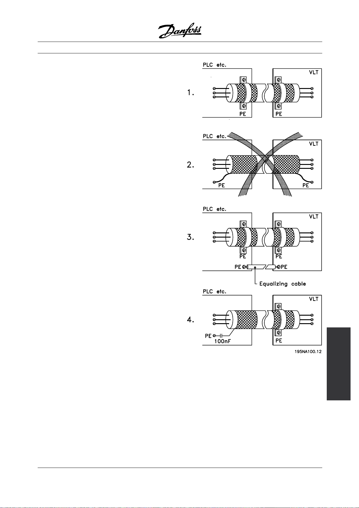
■Grounding of shielded/armoured control cables
In general control cables must be shielded/armoured,
and the shield must be connected to the unit’s metal
cabinet with a cable clamp at each end.
The drawing below shows the correct way to perform
the grounding, and what to do when in doubt.
1. Correct grounding
Control cables and cables for serial
communication must be attached with cable
clamps at both ends to ensure maximum
possible electrical contact.
2. Incorrect grounding
Do not use twisted shield ends that are
plaited together (pigtails), as these increase shield
impedance at higher frequencies.
3. Protection with respect to ground
potential between PLC and VLT
f the ground potential between the VLT
variable frequency drive and the PLC (etc.)
is different, electric noise may occur that will
disturb the whole system. This problem can
be solved by fitting an equalising cable, to be
placed next to the control cable. Minimum cable
cross-section: 6 AWG (16 mm
4. n the event of a 50/60 Hz ground loop
If very long control cables are used, 50/60 Hz
ground loops can arise, and these can interfere
with the whole system. This problem is resolved
by attaching one end of the shield to the gr
via a 100 nF capacitor (short pin length).
2
).
ound
Decentral Solutions
MG.90.F2.22 - VLT is a registered Danfoss trademark
300
Installation, FCD
77
Page 78
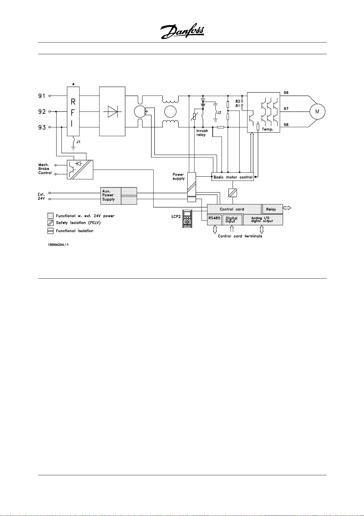
■Diagram
Decentral Solutions
* Integrated brake and mechanical brake control
and external 24 V are options.
■RFI switches J1, J2
J1 and J2 must be removed at IT mains and delta
grounded mains with phase to earth voltage >
300 V also during ground failure.
J1 and J2 can be removed to reduce leakage current.
Caution: No correct RFI filtering.
78
MG.90.F2.22 - VLT is a registered Danfoss trademark
Page 79
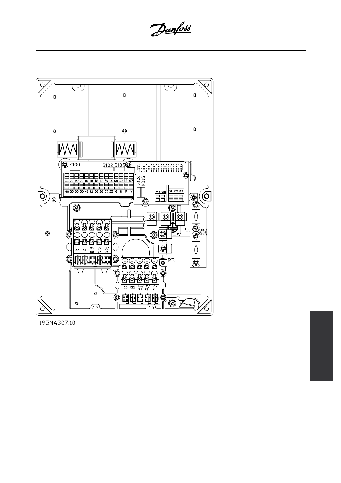
■Location of terminals
Decentral Solutions
T11, T12, T16, T52, T56
MG.90.F2.22 - VLT is a registered Danfoss trademark
300
Installation, FCD
79
Page 80

T22, T26, T62, T66versions with service switch
Decentral Solutions
80
MG.90.F2.22 - VLT is a registered Danfoss trademark
Page 81

Decentral Solutions
T73 version with motor plug and sensor plugs
Version is supplied from Danfoss with wiring as shown
T63 version with service switch (no motor plug)
MG.90.F2.22 - VLT is a registered Danfoss trademark
300
Installation, FCD
81
Page 82

■Electrical connection
No. 91 92 93 AC line voltage 3 x 380-480 V
L1 L2 L3
PE Ground connection
NOTE
Please check that the AC line voltage fits the
mains voltage of the frequency converter, which
can be seen from the nameplate.
See Technical data for correct dimensioning
of cable cross-section.
■Pre-fuses
See Technical data for correct dimensioning
of pre-fuses.
Decentral Solutions
■Direction of motor rotation
■Motor connection
Connect the motor to terminals 96, 97, 98.
Connect ground to PE-terminal.
No. 96 97 98 Motor voltage 0-100% of AC
line voltage
UVW3 wires out of motor
U1W2V1U2W1V26 wires out of motor, Delta
connected
U1 V1 W1 6 wires out of motor, Star
connected
U2, V2, W2 to be
interconnected separately
(optional terminal block)
PE Ground connection
See Technical data for correct dimensioning
of cable cross-section.
All types of three-phase asynchronous standard
motors can be connected to a variable frequency drive.
Normally, small motors are star-connected (230/400 V,
/ Y). Large motors are delta-connected (400/690
/ Y). The correct connection mode and voltage
V,
can be read from the motor nameplate.
The factory setting is for clockwise rotation
with the variable frequency drive transformer
output connected as follows:
Terminal 96 connected to U-phase.
Terminal 97 connected to V-phase.
Terminal 98 connected to W-phase.
The direction of rotation can be changed by switching
two phases on the motor terminals.
NOTE
In motors without phase insulation paper,
an LC filter should be fitted on the output
of the variable frequency drive.
82
MG.90.F2.22 - VLT is a registered Danfoss trademark
Page 83

Decentral Solutions
■AC lines and motor connection with service switch
■Connection of HAN 10E motor plug for T73
■Parallel connection of motors
Thevariablefrequencydriveisabletocontrol
several motors connected in parallel. If the motors
are to have different rpm values, use motors with
different rated rpm values. Motor rpm is changed
simultaneously, which means that the ratio between
the rated rpm values is maintained across the range.
The total current consumption of the motors is
not to exceed the maximum rated output current
I
for the variable frequency drive.
INV
HAN 10E pin no 1 - Motor phase U
HAN 10E pin no 2 - Motor phase V
HAN 10E pin no 3 - Motor phase W
HAN 10E pin no 4 - Motor brake, see Operating
Instructions MG.04.BX.YY, terminal 122
HAN 10E pin no 5 - Motor brake, see Operating
Instructions MG.04.BX.YY, terminal 123
HAN 10E pin no 9 - Motor thermistor, see Operating
Instructions MG.04.BX.YY, terminal 31A
HAN10Epinno10-Motorthermistor,see
Operating Instructions MG.04.BX.YY, terminal 31B
PE = protective ground
Problems may arise at the start and at low rpm
values if the motor sizes are widely different. This
is because the small motors’ relatively high ohmic
resistance in the stator calls for a higher voltage
at the start and at low rpm values.
In systems with motors connected in parallel, the
electronic thermal relay (ETR) of the variable frequency
drive cannot be used as motor protection for the
individual motor. For this reason further motor
protection must be used, e.g. thermistors in each
motor (or an individual thermal relay).
NOTE
Parameter 107 Automatic motor tuning, AMT
cannot be used when motors are connected
in parallel. Parameter 101 Torque characteristic
must be set to Special motor characteristics [8]
when motors are connected in parallel.
■Motor cables
See Technical data for correct sizing of motor cable
cross-section and length. Always comply with national
and local regulations on cable cross-section.
300
Installation, FCD
MG.90.F2.22 - VLT is a registered Danfoss trademark
83
Page 84

Decentral Solutions
NOTE
If an unshielded/unarmoured cable is used,
some EMC requirements are not complied with,
see EMC test results in the Design Guide.
If the EMC specifications regarding emission are
to be complied with, the motor cable must be
shielded/armoured, unless otherwise stated for the
RFI filter in question. It is important to keep the
motor cable as short as possible so as to reduce the
noise level and leakage currents to a minimum. The
motor cable shield must be connected to the metal
cabinet of the variable frequency drive and to the metal
cabinet of the motor. The shield connections are to
be made with the biggest possible surface area (cable
clamp). This is enabled by different installation devices
in different variable frequency drives. Mounting with
twisted shield ends (pigtails) is to be avoided, since
these spoil the shielding effect at high frequencies. If
it is necessary to break the shield to install a motor
isolator or motor relay, the shield must be continued
at the lowest possible HF impedance.
■Motor thermal protection
The electronic thermal relay in UL approved variable
frequency drives has received the UL approval for single
motor protection, when parameter 128 Motor thermal
protection has been set for ETR Trip and parameter
105 Motor current, I
the rated motor current (see motor nameplate).
■Brake resistor
has been programmed to
M, N
NOTE
Please note that voltages up to 850 V DC
occur on the terminals.
■Control of mechanical brake
No. 122
(optional
function)
123
(optional
function)
MBR- MBR+ Mechanical brake
(UDC=0.45 X
electrical Voltage)
Max 0.8 A
In lifting/lowering applications you need to be able
to control an electromagnetic brake. The brake
is controlled using the special mechanical brake
control/supply terminals 122/123.
When the output frequency exceeds the brake cut
out value set in par. 138, the brake is released if the
motor current exceeds the preset value in parameter
140. When stopping the brake is engaged when the
output frequency is less than the brake engaging
frequency, which is set in par. 139.
If the variable frequency drive is at alarm status
or in an overvoltage situation the mechanical
brake is cut in immediately.
If not using the special mechanical brake control/supply
terminals (122-123), select Mechanical brake
control in parameter 323 or 341 for applications
with an electromagnetic brake.
A relay output or digital output (terminal 46) can be used.
See Connection of mechanical brake for further details.
No. 81 (optional
function)
82 (optional
function)
Brake resistor
terminals
R- R+
The connection cable to the brake resistor must
be shielded/armoured. Connect the shield to the
metal cabinet of the variable frequency drive and to
the metal cabinet of the brake resistor by means of
cable clamps. Dimension the cross-section of the
brake cable to match the brake torque.
See chapter Dynamic Braking in the Design Guide
MG.90.FX.YY for sizing of brake resistors.
84
MG.90.F2.22 - VLT is a registered Danfoss trademark
Page 85

Decentral Solutions
■Electrical installation, control cables
Control cables must be shielded/armoured. The
screen must be connected to the variable frequency
converter chassis by means of a clamp. Normally,
the screen must also be connected to the chassis of
the controlling unit (use the instructions for the unit
in question). In connection with very long control
cables and analog signals, in rare cases depending
on the installation, 50/60 Hz ground loops may occur
because of noise transmitted from AC line supply
cables. In this connection, it may be necessary to
break the shield and possibly insert a 100 nF capacitor
between the shield and the chassis.
MG.90.F2.22 - VLT is a registered Danfoss trademark
300
Installation, FCD
85
Page 86

■Connection of sensors to M12 plugs for T73
Decentral Solutions
For rating specifications see the Operating Instructions
MG.04.BX.YY, digital inputs terminals 18, 19, 29, 33.
Terminals 203/204 are used for sensor supply.
Terminal 203 = common
Terminal 204 = +24 V
Terminals 201/202 can be used for a separate
24 V supply.
86
MG.90.F2.22 - VLT is a registered Danfoss trademark
Page 87

Decentral Solutions
■Electrical installation, control terminals
See section entitled Grounding of shielded/armoured
control cables intheDesignGuideforthecorrect
termination of control cables.
No. Function
01-03 Relay outputs 01-03 can be used for
indicating status and alarms/warnings.
12 24 V DC voltage supply.
18-33 Digital inputs.
20, 55 Common frame for input
and output terminals. Can be separated
with switch S100
31a,
Motor thermistor
31b
35 Common (-) for external 24 V control back
up supply. Optional.
36 External + 24 V control back up supply.
Optional.
42 Analog output for displaying frequency,
reference, current or torque.
46 Digital output for displaying status,
warnings or alarms, as well as
frequency output.
50 +10 V DC supply
voltage for potentiometer
53 Analog voltage input 0 - +/- 10 V DC.
60 Analog current input 0/4 - 20 mA.
67 + 5 V DC supply voltage
to Profibus.
68, 69 Fieldbus serial communication*
70 Ground for terminals 67, 68 and 69.
Normally this terminal is not to be used.
D For future use
V +5V, red
P RS485(+), LCP2/PC, yellow
N RS485(-), LCP2/PC, green
G OV, blue
*SeeVLT 2800/FCM 300/FCD 300 Profibus DP
V1 Operating Instructions (MG.90.AX.YY), VLT
2800/FCD 300 DeviceNet Operating Instructions
(MG.90.BX.YY) or FCD 300 AS-interface Operating
Instructions (MG.04.EX.YY).
On non-fieldbus and Profibus variants, terminals
68 and 69 can be used as well.
■Relay connection
See parameter 323 Relay output for programming
of relay output.
No. 01 - 02 1-2make(normallyopen)
01 - 03 1-3break(normallyclosed)
■LCP 2 plug, optional
An LCP 2 control unit can be connected to a
plug which is optionally mounted in the housing.
Ordering number: 175N0131.
LCP control units with ordering number 175Z0401
are not to be connected.
■Installation of 24 Volt external supply (optional)
24 V external DC supply can be used as low-voltage
supply to the control card. This enables full operation
of the LCP2 and serial bus (incl. parameter setting)
without connection to AC input.
Please note that a warning of low voltage will
be given when 24 V DC has been connected;
however there will be no tripping.
NOTE
Use 24 V DC supply of type PELV to
ensure correct galvonic isolation (type
PELV) on the control terminals of the
VLT variable frequency drive.
Beware of unintended start of the
motor, if the electrical power is
applied during operation on the
external 24 V back up supply.
300
Installation, FCD
■PC communication
Connection to terminals P and N.
MG.90.F2.22 - VLT is a registered Danfoss trademark
87
Page 88

■Connection examples
Decentral Solutions
NOTE
Avoid leading the cables over the plugs
to the electronics.
Dont loosen screw fixing the spring
for the PE connection.
88
MG.90.F2.22 - VLT is a registered Danfoss trademark
Page 89

NOTE
In the connection examples below, it should
be noted, that the Switch S100 must not be
changed from factory settings (on).
■Start/stop
Start/stop using terminal 18 and coasting
stop using terminal 27.
Decentral Solutions
■Speed up/slow down
Speed up/slow down using terminals 29/33.
Par. 302 Digital input = Start [7]
Par. 303 Digital input = Freeze reference [14]
Par. 305 Digital input = Speed up [16]
Par. 307 Digital input = Slow down [17]
Par. 302 Digital input = Start [7]
Par. 304 Digital input = Coasting stop inverted [2]
For Precise start/stop the following settings are made:
Par. 302 Digital input = Precise start/stop [27]
Par. 304 Digital input = Coasting stop inverted [2]
■Pulse start/stop
Pulse start using terminal 18 and pulse stop
using terminal 19. In addition, the jog frequency
is activated via terminal 29.
Par. 302 Digital input = Pulse start [8]
Par. 303 Digital input = Stop inverted [6]
Par. 304 Digital input = Coasting stop inverted [2]
Par. 305 Digital input = Jog [13]
■Potentiometer reference
Voltage reference via a potentiometer.
Par. 308 Analog input = Reference [1]
Par. 309 Terminal 53, min. scaling =0Volt
Par. 310 Terminal 53, max. scaling =10Volt
■Connection of a 2-wire transmitter
Connection of a 2-wire transmitter as feedback
to terminal 60.
300
Installation, FCD
MG.90.F2.22 - VLT is a registered Danfoss trademark
Par. 314 Analog input = Feedback [2]
Par. 315 Terminal 60, min. scaling =4mA
89
Page 90

Par. 316 Terminal 60, max . scaling =20mA
■4-20 mA reference
4-20 mA reference on terminal 60 and speed
feedback signal on terminal 53.
Par. 100 Configuration = Speed closed loop [1]
Par. 308 Analog input = Feedback [2]
Par. 309 Terminal 53, min. scaling =0Volt
Par. 310 Terminal 53, max. scaling =10Volt
Par. 314 Analog input = Reference [1]
Par. 309 Terminal 60, min. scaling =4mA
Par. 310 Teminal 60, max. scaling =20mA
■ 50 Hz counter-clockwise to 50 Hz clockwise.
With internally supplied potentiometer.
Decentral Solutions
Par. 100 Configuration = Speed regulation
open loop [0]
Par. 200 Output frequency range = Both
directions, 0-132 Hz [1]
Par. 203 Reference range = Min. ref. - Max. ref. [0]
Par. 204 Min. reference =-50Hz
Par. 205 Max. reference =50Hz
Par. 302 Digital input = Start [7]
Par. 304 Digital input = Coasting stop inverted [2]
Par. 308 Analog input = Reference [1]
Par. 309 Terminal 53, min. scaling =0Volt.
Par. 310 Terminal 53, max. scaling =10Volt.
■Preset references
Switch between 8 preset references via two digital
inputs and Setup 1 and Setup 2.
Par. 004 Active Setup = Multisetup 1 [5]
Par. 204 Min. reference =0Hz
Par. 205 Max. reference =50Hz
Par. 302 Digital input = Start [7]
Par. 303 Digital input = Choice of Setup, lsb [31]
Par. 304 Digital input = Coasting stop inverted [2]
Par. 305 Digital input = Preset ref., lsb [22]
Par. 307 Digital input = Preset ref., msb [23]
90
Setup 1 contains the following preset references:
MG.90.F2.22 - VLT is a registered Danfoss trademark
Page 91

Par. 215 Preset reference 1 = 5.00%
Par. 216 Preset reference 2 = 10.00%
Par. 217 Preset reference 3 = 25.00%
Par. 218 Preset reference 4 = 35.00%
Setup 2 contains the following preset references:
Par. 215 Preset reference 1 = 40.00%
Par. 216 Preset reference 2 = 50.00%
Par. 217 Preset reference 3 = 70.00%
Par. 218 Preset reference 4 = 100.00%
Decentral Solutions
This table shows what the output frequency is:
Preset
ref., msb
0 0 0 2.5
0 1 0 5
1 0 0 10
1 1 0 17.5
0 0 1 20
0 1 1 25
1 0 1 35
1 1 1 50
■Connection of mechanical brake
Using terminal 122/123
Preset
ref., lsb
Selection
of Setup
Output
frequency[Hz]
Par. 302 Digital input = Start [7]
Par. 304 Digital input = Coasting stop inverted [2]
See also par. 138, 139, 140
Mechanical brake with accelerator winding
Par. 302 Digital input = Start [7]
Par. 304 Digital input = Coasting stop inverted [2]
See also par. 138, 139, 140
300
Installation, FCD
MG.90.F2.22 - VLT is a registered Danfoss trademark
91
Page 92

Use of the relay for 230 V AC brake
Par. 302 Digital input = Start [7]
Par. 304 Digital input = Coasting stop inverted [2]
Par. 323 Relay output = Mech anical
brake control [25]
See also par. 138, 139, 140
Decentral Solutions
Mechanical brake control [25] = ’0’ => Brake is closed.
Mechanical brake control [25] = ’1’=> The brake is open.
See more detailed parameter settings under
Control of mechanical brake .
NOTE
Do not use the internal relay for DC brakes
or brake voltages > 250 V.
■Counter stop via terminal 33
The start signal (terminal 18) must be active, i.e. logical
’1’, until the output frequency is equal to the reference.
The start signal (terminal 18 = logical ’0’) must then be
removed before the counter value in parameter 344
has managed to stop the VLT frequency converter.
Par. 307 Digital input = Pulse input [30]
Par. 343 Precise stop function = Counter
stop with reset [1]
Par. 344 Counter value = 100000
92
MG.90.F2.22 - VLT is a registered Danfoss trademark
Page 93
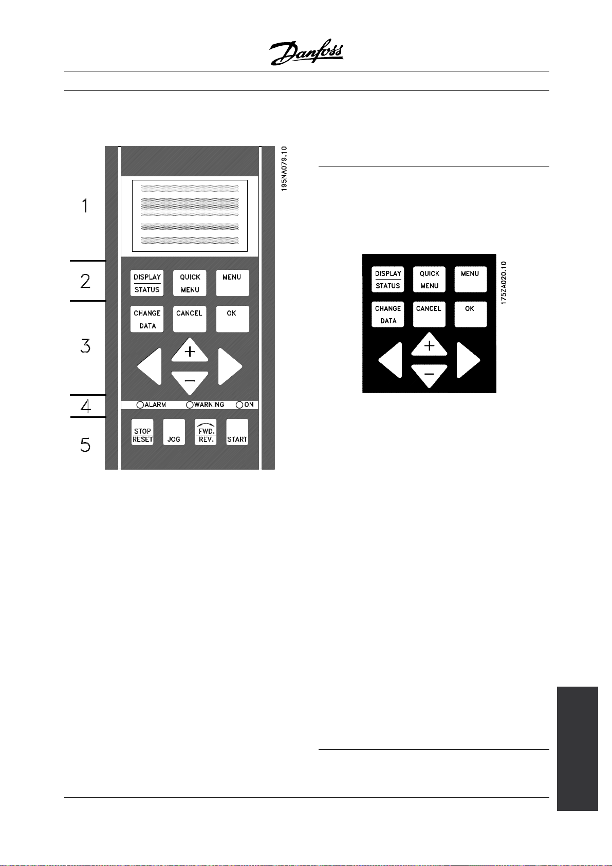
Decentral Solutions
■The LCP 2 control unit, option
changed immediately from the control panel, unless
this function has been programmed as Locked [1]
via parameter 018 Lock for data changes.
■Control keys for parameter Setup
The control keys are divided into functions, in such a
way that the keys between the display and the indicator
lamps are used for parameter Setup, including selection
of the display’s view mode during normal operation.
[DISPLAY/STATUS] is used to select the display’s
view mode or to change back to Display mode
from either Quick Menu or Menu mode.
The FCD 300 can be combined with an LCP control
unit (Local Control Panel - LCP 2) which makes up a
complete interface for operation and programming of
the variable frequency drive. The LCP 2 control unit can
be attached up to nine feet from the variable frequency
drive, e.g. on a front panel, using an accessory kit.
The control panel is divided into five functional groups:
1. Display.
2. Keys used to change the display function.
3. Keys used to change the program parameters.
4. LEDs.
5. Local control keys.
Alldataisdisplayedviaa4-linealphanumeric
display, which during normal operation will be able
to continuously display 4 items of operating data
and 3 operating modes. During programming all
information needed for quick, effective parameter setup
of the variable frequency drive will be displayed. As
a supplement to the display, there are three LEDs for
voltage (ON), warning (WARNING) and alarm (ALARM).
All variable frequency drive parameter Setups can be
[QUICK MENU] provides access to the parameters
used in the Quick Menu. It is possible to switch
between Quick Menu and Menu mode.
[MENU] gives access to all parameters. It is possible
to switch between Menu mode and Quick Menu.
[CHANGE DATA] is used to change a parameter that
has been selected either in Menu mode or Quick Menu.
[CANCEL] is used if a change to the selected
parameter is not to be implemented.
[OK] is used to confirm a change to a
selected parameter.
[+ / -] are used for selecting parameters and
for changing parameter values.
These keys are also used in Display mode to switch
between the readouts of operating variables.
[< >] are used for selecting parameter group and to
move the cursor when changing a numerical value.
300
Programming, FCD
MG.90.F2.22 - VLT is a registered Danfoss trademark
93
Page 94

Decentral Solutions
■LEDs
At the bottom of the control panel are a red alarm light, a
yellow warning light and a green voltage indicator light.
If certain threshold values are exceeded, the alarm
and/or warning light are activated, while a status
or alarm text is shown on the display.
NOTE
The voltage indicator light is activated
when voltage is connected to the variable
frequency drive.
■Local control
NOTE
If the local control keys are set to inactive,
these will both become active when the variable
frequency drive is set to Local control and
Remote control via parameter 002 Local/remote
operation, with the exception of [FWD/REV], which
is only active in Local control.
[STOP/RESET] is used for stopping the motor
connected or for resetting the variable frequency
drive after a drop-out (trip). Can be set to active or
inactive via parameter 014 Local stop.
If stop is activated Display line 2 will flash.
NOTE
If an external stop function is not selected and
the [STOP/RESET] key is set to inactive, the
motor can only be stopped by disconnecting
the voltage to the motor or the variable frequency drive.
[JOG] changes the output frequency to a preset
frequency while the key is held down. Can be set to
active or inactive via parameter 015 Local jog.
[FWD / REV] changes the direction of rotation of
the motor, which is indicated by means of the arrow
on the display. Can be set to active or inactive via
parameter 016 Local reverse. The [FWD/REV] key
is only active when parameter 002 Local/remote
operation is set to Local control.
[START] is used to start the variable frequency drive.
Is always active, but cannot override a stop command.
94
MG.90.F2.22 - VLT is a registered Danfoss trademark
Page 95
Decentral Solutions
■Display mode
VAR 1.1 VAR 1.2 VAR 1.3
SETUP
VAR 2
1
STATUS
In normal operation, up to 4 different display data
items can optionally be shown continuously: 1,1,
1,2, 1,3 and 2. The present operation status or
alarms and warnings that have been generated are
displayed in line 2 in the form of a number.
In the event of alarms this is displayed in lines
3 and 4 with explanatory text.
A warning will appear flashing in line 2 with
explanatory text in line 1. The active Setup will
also appear on the display.
The arrow indicates the selected direction of rotation.
Here the variable frequency drive shows that it has
an active reverse signal. The body of the arrow
will disappear if a stop command is given, or if the
output frequency drops below 0.1 Hz.
Thebottomlinedisplaysthefrequencytransformer’s
status. The scrollbar shows which operating values
can be displayed in lines 1 and 2 in Display mode.
Changes are made using the [+ / -] keys.
Switching between AUTO and HAND modes
By activating the [CHANGE DATA] key in [DISPLAY
MODE] the display will indicate the mode of
the variable frequency drive.
Operating data Unit
Resulting reference [%]
195NA113.10
Resulting reference [unit]
Feedback [unit]
Output frequency [Hz]
Output frequency x scaling [-]
Motor current [A]
Torque [%]
Power [kW]
Power [HP]
Motor voltage [V]
DC link voltage [V]
Thermal load motor [%]
Thermal load [%]
Hours run [hours]
Digital input [binary]
Pulse input 29 [Hz]
Pulse input 29 [Hz]
Pulse input 33 [Hz]
External reference [%]
Status word [hex]
Heatsink temperature [°C]
Alarm word [hex]
Control word [hex]
Warning word [hex]
Extended status word [hex]
Analog input 53 [V]
Analog input 60 [mA]
Three operating data items can be shown in the
first display line, and one operating variable can be
shown in the second display line. Is programmed via
parameters 009, 010, 011 and 012 Display readout .
Switch mode by using [+/-] key [HAND...AUTO]
In [HAND] mode the reference can be changed
by [+] or [-] keys.
MG.90.F2.22 - VLT is a registered Danfoss trademark
300
Programming, FCD
95
Page 96

■Display modes
The LCP control unit has different display modes,
which depend on the mode selected for the
variable frequency drive.
Display mode I:
This display mode is standard after startup
or initialization.
FREQUENCY
50.0 Hz
MOTOR IS RUNNING
Line 2 shows the data value of an operating data
item with unit, and line 1 contains a text that explains
line 2. In the example, Frequency has been selected
as readout via parameter 009 Large display readout.
In normal operation, another variable can be entered
immediately using the [+ / -] keys.
Decentral Solutions
Here you can read out the parameter names and
units for operating data in the first and second lines.
Line 2 in the display remains unchanged.
Display mode II:
Switch between Display modes I and II is perfo
by briefly pressing the [DISPLAY / STATUS] key.
24.3% 30.2% 13.8A
rmed
50.0 Hz
MOTOR IS RUNNING
In this mode, all data values for four operating
data items with any pertaining units are shown,
see table. In the example, the following have been
selected: Frequency, Reference, Torqu e and Current
as readout in the first and second line.
Display mode III:
This dis
/ STATUS] key is held down. When the key is released
it switches back to Display mode II, unless the key is
held d
the system always reverts to Display mode I.
play mode is called up as long as the [DISPLAY
own for less than approx. 1 sec., in which case
96
REF% TORQUE CURR A
50.0 Hz
MOTOR IS RUNNING
SETUP
1
MG.90.F2.22 - VLT is a registered Danfoss trademark
Page 97

DisplaymodeIV:
This display mode can be called up during operation
if a change has to be made in another Setup without
stopping the variable frequency drive. This function is
activated in parameter 005 Programming Setup.
Decentral Solutions
parameters will be "shaded off", depending on the
choice in parameter 100 Configuration .
■Quick menu with LCP 2 control unit
Start Quick Setup by pressing the [QUICK MENU] key,
which will bring out the following display values:
24.3% 30.2% 13.8A
SETUP
50.0 Hz
MOTOR IS RUNNING
12
Here the programming Setup number 2 will flash
to the right of the active Setup.
■Parameter Setup
A variable frequency drive’s comprehensive work area
can be accessed via a large number of parameters,
making it possible to adapt its functionality for a specific
application. To provide a better overview of the many
parameters, there is a choice of two programming
modes - Menu mode and Quick Menu mode. The
former provides access to all parameters. The latter
takes the user through the parameters, which make it
possible to start operating the variable frequency drive
in most cases, in accordance with the Setup made.
Regardless of the mode of programming, a change
of a parameter will take effect and be visible both in
theMenumodeandintheQuickmenumode.
QUICK MENU X OF Y
50.0 Hz
001 LANGUAGE
ENGLISH
SETUP
1
At the bottom of the display, the parameter number
and name are given together with the status/value
of the first parameter under the Quick menu. The
first time the [QUICK MENU] key is pressed after
the unit has been switched on, the readouts always
start in pos. 1 - see table below.
Pos. Parameter no. Unit
1 001 Language
2 102 Motor power [kW]
3 103 Motor voltage [V]
4 104 Motor frequency [Hz]
5 105 Motor current [A]
6 106 Rated motor speed [rpm]
7 107 AMT
8 204 Minimum reference [Hz]
9 205 Maximum reference [Hz]
10 207 Ramp-up time [sec]
11 208 Ramp-down time [sec]
12 002 Local/remote operation
13 003 Local reference [Hz]
Structure for Quick menu mode v Menu mode
In addition to having a name, each parameter is linked
up with a number which is the same regardless of
the programming mode. In Menu mode, parameters
will be split into groups, with the first digit (left)
of the parameter number indicating the group
number of the parameter in question.
• Using the [QUICK MENU] key, it is possible to get
access to the most important parameters of the
variable frequency drive. After programming, the
variable frequency drive is in most cases ready
for operation. Scroll through the Quick menu
using the [+ / -] keys and change the data values
by pressing [CHANGE DATA] + [OK].
• The Menu mode allows choosing and changing
all parameters as required. However, some
MG.90.F2.22 - VLT is a registered Danfoss trademark
■Parameter selection
Menu mode is started by pressing the [MENU] key,
which produces the following readout on the display:
FREQUENCY
50.0 Hz
0 KEYB.&DISPLAY
Line 3 on the display shows the parameter
group number and name.
In Menu mode, the parameters are divided
into groups. Selection of parameter group is
effected using the [< >] keys.
The following parameter groups will be accessible:
300
Programming, FCD
97
Page 98
Decentral Solutions
Group no. Parameter group
0 Operation & Display
1Load&Motor
2 References & Limits
3 Inputs & Outputs
4 Special functions
5 Serial communication
6 Technical functions
When the required parameter group has been
selected, each parameter can be chosen by
means of the [+ / -] keys:
FREQUENCY
50.0 Hz
001 LANGUAGE
ENGLISH
The 3rd line of the display shows the parameter
number and name, while the status/value of the
selected parameter is shown in line 4.
Changing data
Regardless of whether a parameter has been
selected under the Quick menu or the Menu mode,
the procedure for changing data will be the same.
Pressing the [CHANGE DATA] key gives access
to changing the selected parameter, following
which the underlining in line 4 will flash on the
display. The procedure for changing data depends
on whether the selected parameter represents a
numerical data value or a text value.
Changing a data value
If the selected parameter is a text value, the text value
is changed by means of the [+ / -] keys.
FREQUENCY
50.0 Hz
001 LANGUAGE
ENGLISH
FREQUENCY
50.0 Hz
130 START FREQUENCY
09.0 HZ
SETUP
1
The selected digit can then be changed infinitely
variably using the [+ / -] keys:
FREQUENCY
50.0 Hz
130 START FREQUENCY
10.0 HZ
SETUP
1
The chosen digit is indicated by the digit flashing. The
bottom display line shows the data value that will be
entered (saved) when signing off with [OK].
■ Manual initialization
NOTE
Manual initialization is n
ot possible on
the LCP 2 175N0131 control unit. It is,
however, possible to perform an initialization
via par. 620 Operation mode:
The following parameters are not changed when
initializing via par. 620 Operation mode.
-par.500Address
- par. 501 Baud rate
- par. 600 Operating hours
- par. 601 Hours run
- par. 602 kWh counter
- par. 603 Number of power-ups
- par. 604 Number of overheatings
- par. 605 Number of overheatings
- par. 615-617 Fault log
- par. 678 Configure Control Card
The bottom display line will show the value that will be
entered (saved) when acknowledgment is given [OK].
Change of numeric data value
If the selected parameter is represented by a numerical
data value, a digit is first chosen using the [< >] keys.
98
MG.90.F2.22 - VLT is a registered Danfoss trademark
Page 99

Decentral Solutions
■Operation & Display
001 Language
(LANGUAGE)
Value:
✭English (ENGLISH)
German (DEUTSCH)
French (FRANCAIS)
Danish (DANSK)
Spanish (ESPANOL)
Italian (ITALIANO)
Function:
This parameter is used to choose the language
to be shown in the display whenever the LCP
control unit is connected.
Description of choice:
There is a choice of the languages shown. The
factory setting may vary.
002 Local/remote operation
(OPERATION SITE)
Value:
✭Remote operation (REMOTE)
Local operation (LOCAL)
Function:
There is a choice of two different modes of operation
of the variable frequency drive. Remote operation [0]
or Local operation [1]. See also parameter 013 Local
control if Local operation [1] is selected.
Description of choice:
If Remote operation [0] is selected, the variable
frequency drive is controlled via:
1. the control terminals or via serial communication.
2. the [START] key. This cannot, however, override
stop commands transmitted via the digital inputs
or via serial communication.
3. the [STOP/RESET] and [JOG] keys, on the
condition that these are active.
If Local operation [1], is selected, the variable
frequency drive is controlled via:
1. the [START] key. This cannot, however, override
stop commands via the digital inputs (see
parameter 013 Local control).
2. the [STOP/RESET] and [JOG] keys, on the
condition that these are active.
3. the [FWD/REV] key, on the condition that is has
been selected as active in parameter 016 Local
reversing, and that parameter 013 Local control
[0]
[1]
[2]
[3]
[4]
[5]
is set at Local c o ntrol and open loop [1] or Local
control as parameter 100 [3]. Parameter 200
Output frequency range is set at Both directions.
4. parameter 003 Local reference where the reference
can be set using the [+] and [-] keys.
5. an external control command that can be
connected to the digital inputs (see parameter
013 Local control).
NOTE
The [JOG] and [FWD/REV] keys are located
on the LCP control unit.
003 Local reference
(LOCAL REFERENCE)
Value:
Par.013 Local control must be set to [1] or [2]:
0-f
MAX
[0]
[1]
Par. 013 Local control must be set to [3] or [4] and
parameter 203 Reference/feedback range to [0]:
Ref
MIN
-Ref
Par. 013 Local control must be set to [3] or [4] and
parameter 203 Reference/feedback range to [1]:
-Ref
MAX
Function:
In this parameter, the local reference can be set
manually. The unit of the local reference depends on the
configuration selected in parameter 100 Configuration.
Description of choice:
In order to protect the local reference, parameter
002 Local/remote operation must be set to
Local operation [1]. Local reference cannot be
set via serial communication.
■Setup configuration
There is a choice of four Setups (parameter Setups),
which can be programmed independently of one
(par. 202)
(par. 204-205)
MAX
-+Ref
MAX
(par. 204-205)
✭ 000,000.000
✭ 000,000.000
✭ 000,000.000
300
✭
= factory setting. () = display text [] = value for use in communication via serial communication port
MG.90.F2.22 - VLT is a registered Danfoss trademark
Programming, FCD
99
Page 100

Decentral Solutions
another. The active Setup can be selected in parameter
004 Active Setup. WhenanLCPcontrolunitis
connected, the active Setup number will be appear
in the display under "Setup". It is also possible to
preset the variable frequency drive to Multisetup,so
that it is possible to shift Setups using the digital inputs
or serial communication. Setup shift can be used
in a plant in which, for example, one Setup is used
for daytime operation and another one at night time.
In parameter 006 Setup copying it is possible to
copy from one Setup to another. Using parameter
007 LCP copy all Setups can be transferred from
one variable frequency drive to another by moving
the LCP control panel. First all parameter val ues
are copied to the LCP control panel, which can then
be moved to another variable frequency drive. Here
all parameter values can be copied from the LCP
control unit to the variable frequency drive.
■Setup shift
be made in this parameter via a digital input
or via serial communication.
Description of choice:
Factory Setup [0] contains the factory-set parameter
values. Setup 1-4 [1]-[4] are four individual
Setups which can be selected as required. Multi
Setup [5] is used where remote-controlled shifts
betweenthefourSetupsviaadigitalinputorvia
serial communication is required.
005 Programming Setup
(EDIT SETUP)
Value:
Factory Setup (FACTORY SETUP)
Setup 1 (SETUP 1)
Setup 2 (SETUP 2)
Setup 3 (SETUP 3)
Setup 4 (SETUP 4)
✭Active Setup (ACTIVE SETUP)
[0]
[1]
[2]
[3]
[4]
[5]
Function:
You can select which Setup you want to program
during operation (applies both via the control panel
and the serial communication port). It is, for example,
possible to program Setup 2 [2], while the active Setup
is set to Setup 1 [1] in parameter 004 Active Setup .
Description of choice:
- Selection of Setup via terminals 29 and 33.
Par. 305 Digital input = Selection of Setup, lsb [31]
Par. 307 Digital input = Selection of Setup, msb [32]
Par. 004 Active setup = Multi Setup [5]
004 Active Setup
(ACTIVE SETUP)
Value:
Factory Setup (FACTORY SETUP)
✭setup 1 (SETUP 1)
setup 2 (SETUP 2)
Setup 3 (SETUP 3)
setup 4 (SETUP 4)
Multi Setup (MULTI SETUP)
Function:
The active parameter Setup is selected here. All
parameters can be programmed in four individual
parameter Setups. Shifts between Setups can
✭
= factory setting. () = display text [] = value for use in communication via serial communication port
[0]
[1]
[2]
[3]
[4]
[5]
Factory Setup [0] contains the factory-set data and can
be used as a source of data if the other Setups are to be
reset to a known status. Setup 1-4 [1]-[4] are individual
Setups that can be programmed freely during operation.
If Active Setup [5] is selected, the programming Setup
will be equal to parameter 004 Active Setup.
NOTE
If data is modified or copied to the active
Setup, the modifications have an immediate
effect on the unit’soperation.
006 Setup copying
(SETUP COPY)
Value:
✭No copying (NO COPY)
Copy to Setup 1 from #
(COPY TO SETUP 1)
[0]
[1]
100
MG.90.F2.22 - VLT is a registered Danfoss trademark
 Loading...