

Page 1
MAKING MODERN LIVING POSSIBLE
Design Guide
VLT® AutomationDrive FC 360
Page 2

Page 3

Contents
Contents
VLT® AutomationDrive FC 360 Design Guide
1 Introduction
1.1 How to Read This Design Guide
1.1.1 Symbols 5
1.1.2 Abbreviations 5
1.2 Definitions
1.2.1 Frequency Converter 6
1.2.2 Input 6
1.2.3 Motor 6
1.2.4 References 6
1.2.5 Miscellaneous 7
1.3 Safety Precautions
1.4 Software Version
1.5 CE Labelling
1.6 Air Humidity
2 Product Overview
2.1 Enclosure Type Overview
2.2 Electrical Installation
5
5
6
8
9
10
11
12
12
13
2.3 Control Structures
2.3.1 Control Principle 14
2.3.2 FC 360 Controls 14
2.3.3 Control Structure in VVC
2.3.4 Internal Current Control in VVC
2.3.5 Local (Hand On) and Remote (Auto On) Control 16
plus
plus
Mode 16
2.4 Reference Handling
2.4.1 Reference Limits 18
2.4.2 Scaling of Preset References and Bus References 19
2.4.3 Scaling of Analog and Pulse References and Feedback 19
2.4.4 Dead Band Around Zero 21
2.5 PID Control
2.5.1 Speed PID Control 24
2.5.2 Process PID Control 27
2.5.3 Process Control Relevant Parameters 28
2.5.4 Example of Process PID Control 29
2.5.5 Optimisation of the Process Regulator 31
14
15
17
24
2.5.6 Ziegler Nichols Tuning Method 31
2.6 General Aspects of EMC
2.6.1 General Aspects of EMC Emissions 32
2.6.2 EMC Test Results 33
MG06B202 - VLT® is a registered Danfoss trademark 1
32
Page 4

Contents
VLT® AutomationDrive FC 360 Design Guide
2.6.3 Immunity Requirements 34
2.7 Galvanic Isolation (PELV)
2.7.1 PELV - Protective Extra Low Voltage 35
2.8 Earth Leakage Current
2.9 Brake Functions
2.9.1 Mechanical Holding Brake 37
2.9.2 Dynamic Braking 37
2.9.3 Selection of Brake Resistor 37
2.10 Smart Logic Controller
2.11 Extreme Running Conditions
2.11.1 Motor Thermal Protection 40
3 RS-485 Installation and Set-up
3.1 Introduction
3.1.1 Overview 41
3.1.2 Network Connection 41
3.1.3 Frequency Converter Hardware Set-up 41
3.1.4 Frequency Converter Parameter Settings for Modbus Communication 41
3.1.5 EMC Precautions 42
35
35
37
39
39
41
41
3.2 FC Protocol Overview
3.3 Network Configuration
3.4 FC Protocol Message Framing Structure
3.4.1 Content of a Character (byte) 42
3.4.2 Telegram Structure 43
3.4.3 Telegram Length (LGE) 43
3.4.4 Frequency Converter Address (ADR) 43
3.4.5 Data Control Byte (BCC) 43
3.4.6 The Data Field 44
3.4.7 The PKE Field 44
3.4.8 Parameter Number (PNU) 45
3.4.9 Index (IND) 45
3.4.10 Parameter Value (PWE) 45
3.4.11 Data Types Supported by the Frequency Converter 46
3.4.12 Conversion 46
3.4.13 Process Words (PCD) 46
3.5 Examples
42
42
42
46
3.6 Modbus RTU Overview
3.6.1 Assumptions 47
3.6.2 What the User Should Already Know 47
3.6.3 Modbus RTU Overview 47
3.6.4 Frequency Converter with Modbus RTU 48
2 MG06B202 - VLT® is a registered Danfoss trademark
47
Page 5

Contents
VLT® AutomationDrive FC 360 Design Guide
3.7 Network Configuration
3.8 Modbus RTU Message Framing Structure
3.8.1 Frequency Converter with Modbus RTU 48
3.8.2 Modbus RTU Message Structure 48
3.8.3 Start/Stop Field 49
3.8.4 Address Field 49
3.8.5 Function Field 49
3.8.6 Data Field 49
3.8.7 CRC Check Field 49
3.8.8 Coil Register Addressing 49
3.8.9 How to Control the Frequency Converter 52
3.8.10 Function Codes Supported by Modbus RTU 52
3.8.11 Modbus Exception Codes 52
3.9 How to Access Parameters
3.9.1 Parameter Handling 52
3.9.2 Storage of Data 53
3.9.3 IND 53
48
48
52
3.9.4 Text Blocks 53
3.9.5 Conversion Factor 53
3.9.6 Parameter Values 53
3.10 Examples
3.10.1 Read Coil Status (01 HEX) 53
3.10.2 Force/Write Single Coil (05 HEX) 54
3.10.3 Force/Write Multiple Coils (0F HEX) 54
3.10.4 Read Holding Registers (03 HEX) 54
3.10.5 Preset Single Register (06 HEX) 55
3.10.6 Preset Multiple Registers (10 HEX) 55
3.11 Danfoss FC Control Profile
3.11.1 Control Word According to FC Profile (8-10 Protocol = FC profile) 56
3.11.2 Status Word According to FC Profile (STW) (8-30 Protocol = FC profile) 57
3.11.3 Bus Speed Reference Value 58
4 Application Examples
4.1 Introduction
4.1.1 Encoder Connection 62
53
56
59
59
4.1.2 Encoder Direction 62
4.1.3 Closed Loop Drive System 62
5 Type Code and Selection
5.1 Ordering from FC 360 Series
5.1.1 Drive Configurator 64
MG06B202 - VLT® is a registered Danfoss trademark 3
63
63
Page 6

Contents
VLT® AutomationDrive FC 360 Design Guide
5.2 Options and Accessories
5.3 Brake Resistors
5.3.1 Ordering Numbers: Brake Resistors 10% 65
5.3.2 Ordering Numbers: Brake Resistors 40% 66
5.4 Sine-wave Filters
6 Specifications
6.1 Power-dependent Specifications
6.1.1 Mains Supply 3 x 380-480 V AC 67
6.2 General Specifications
6.3 Fuse Specifications
6.3.1 Fuses 73
6.3.2 Recommendations 73
6.3.3 CE Compliance 73
6.4 Efficiency
6.5 Acoustic Noise
6.6 dU/dt Conditions
6.7 Special Conditions
64
64
66
67
67
69
73
74
74
74
75
Index
6.7.1 Manual Derating 75
6.7.2 Automatic Derating 76
77
4 MG06B202 - VLT® is a registered Danfoss trademark
Page 7
Introduction
VLT® AutomationDrive FC 360 Design Guide
1 Introduction
1.1 How to Read This Design Guide
This Design Guide will introduce all aspects of the
frequency converter.
Available literature
-
The VLT® AutomationDrive FC 360 Quick Guide
provides the necessary information for getting
the drive up and running.
-
The VLT® AutomationDrive FC 360 Design Guide
entails all technical information about the drive
and customer design and applications.
-
The VLT® AutomationDrive FC 360 Programming
Guide provides information on how to
programme and includes complete parameter
descriptions.
Danfoss Drives technical literature is also available online
at www.danfoss.com/BusinessAreas/DrivesSolutions/
Documentations/Technical+Documentation.
Symbols
1.1.1
The following symbols are used in this manual.
WARNING
Indicates a potentially hazardous situation which, if not
avoided, could result in death or serious injury.
CAUTION
Indicates a potentially hazardous situation which, if not
avoided, may result in minor or moderate injury. It may
also be used to alert against unsafe practices.
CAUTION
Indicates a situation that may result in equipment or
property-damage-only accidents.
NOTE
Indicates highlighted information that should be regarded
with attention to avoid mistakes or operate equipment at
less than optimal performance.
1.1.2
Abbreviations
Alternating current AC
American wire gauge AWG
Ampere/AMP A
Automatic Motor Adaptation AMA
Current limit I
Degrees Celsius
Direct current DC
Drive Dependent D-TYPE
Electro Magnetic Compatibility EMC
Electronic Thermal Relay ETR
Gram g
Hertz Hz
Horsepower hp
Kilohertz kHz
Local Control Panel LCP
Meter m
Millihenry Inductance mH
Milliampere mA
Millisecond ms
Minute min
Motion Control Tool MCT
Nanofarad nF
Newton Meters Nm
Nominal motor current I
Nominal motor frequency f
Nominal motor power P
Nominal motor voltage U
Parameter par.
Permanent Magnet motor PM motor
Protective Extra Low Voltage PELV
Printed Circuit Board PCB
Rated Inverter Output Current I
Revolutions Per Minute RPM
Regenerative terminals Regen
Second sec.
Synchronous Motor Speed n
Torque limit T
Volts V
The maximum output current I
The rated output current supplied by the
frequency converter
Table 1.1 Abbreviations
LIM
°C
M,N
M,N
M,N
M,N
INV
s
LIM
VLT,MAX
I
VLT,N
1 1
* Indicates default setting
MG06B202 - VLT® is a registered Danfoss trademark 5
Page 8
175ZA078.10
Pull-out
rpm
Torque
Introduction
VLT® AutomationDrive FC 360 Design Guide
11
1.2 Definitions
1.2.1 Frequency Converter
I
VLT, MAX
Maximum output current.
I
VLT,N
Rated output current supplied by the frequency converter.
U
VLT,MAX
n
slip
Motor slip.
P
M,N
Rated motor power (nameplate data in kW or HP).
T
M,N
Rated torque (motor).
U
M
Instantaneous motor voltage.
U
M,N
Rated motor voltage (nameplate data).
Maximum output voltage.
Input
1.2.2
Control command
Start and stop the connected motor by means of LCP and
digital inputs.
Functions are divided into two groups.
Functions in group 1 have higher priority than functions in
group 2.
Group 1 Reset, Coasting stop, Reset and Coasting stop,
Quick-stop, DC braking, Stop and the [OFF] key.
Group 2 Start, Pulse start, Reversing, Start reversing, Jog
and Freeze output
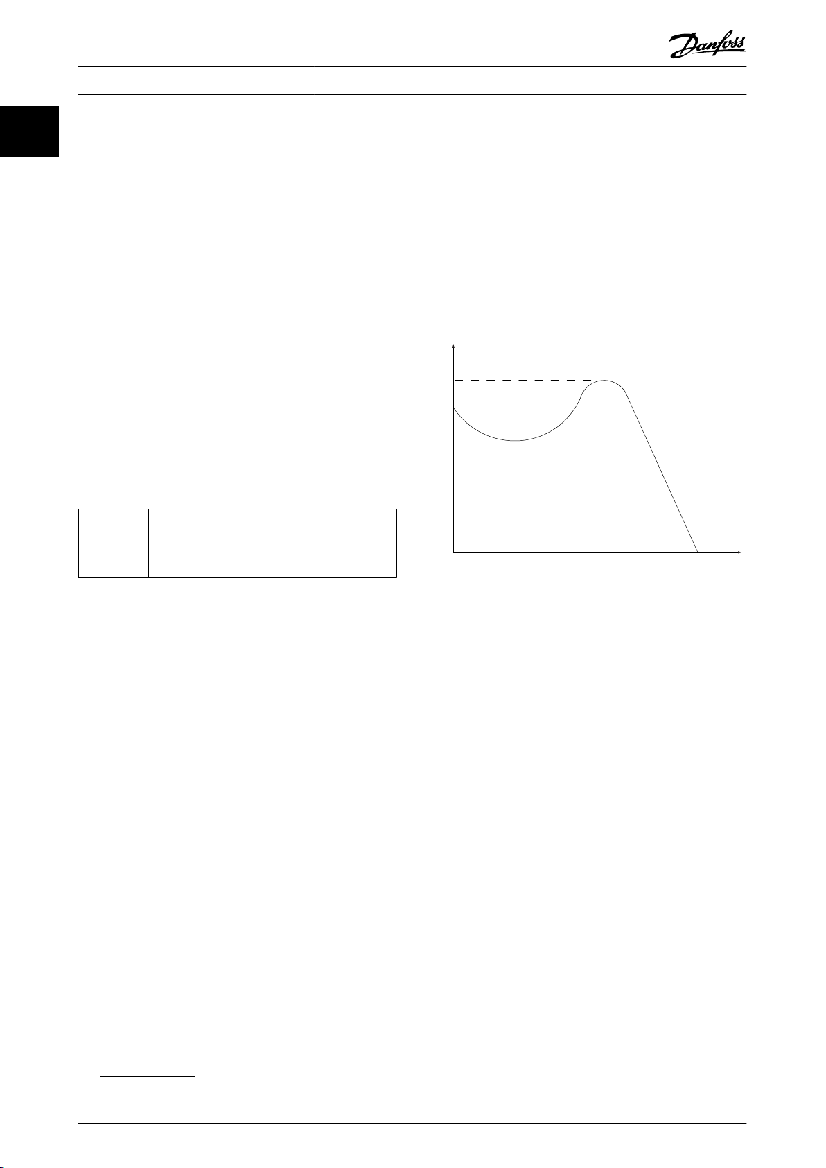
Illustration 1.1 Break-away Torque
1.2.3 Motor
Motor Running
Torque generated on output shaft and speed from zero
rpm to max. speed on motor.
f
JOG
Motor frequency when the jog function is activated (via
digital terminals).
f
M
Motor frequency.
f
MAX
Maximum motor frequency.
f
MIN
Minimum motor frequency.
f
M,N
Rated motor frequency (nameplate data).
I
M
Motor current (actual).
I
M,N
Rated motor current (nameplate data).
n
M,N
Rated motor speed (nameplate data).
n
s
Synchronous motor speed
2 ×
par
n
=
s
. 1 − 23 × 60
par
. 1 − 39
s
Break-away torque
η
VLT
The efficiency of the frequency converter is defined as the
ratio between the power output and the power input.
Start-disable command
A stop command belonging to the group 1 control
commands - see this group.
Stop command
See Control commands.
References
1.2.4
Analog Reference
A signal transmitted to the analog inputs 53 or 54, can be
voltage or current.
Binary Reference
A signal transmitted to the serial communication port.
Preset Reference
A defined preset reference to be set from -100% to +100%
of the reference range. Selection of eight preset references
via the digital terminals.
Pulse Reference
A pulse frequency signal transmitted to the digital inputs
(terminal 29 or 33).
6 MG06B202 - VLT® is a registered Danfoss trademark
Page 9

Introduction
VLT® AutomationDrive FC 360 Design Guide
Ref
MAX
Determines the relationship between the reference input
at 100% full scale value (typically 10 V, 20 mA) and the
resulting reference. The maximum reference value set in
3-03 Maximum Reference.
Ref
MIN
Determines the relationship between the reference input
at 0% value (typically 0 V, 0 mA, 4 mA) and the resulting
reference. The minimum reference value set in
3-02 Minimum Reference.
1.2.5 Miscellaneous
Analog Inputs
The analog inputs are used for controlling various
functions of the frequency converter.
There are two types of analog inputs:
Current input, 0-20 mA and 4-20 mA
Voltage input, -10 to +10 V DC.
Analog Outputs
The analog outputs can supply a signal of 0-20 mA, 4-20
mA.
Automatic Motor Adaptation, AMA
AMA algorithm determines the electrical parameters for
the connected motor at standstill.
Brake Resistor
The brake resistor is a module capable of absorbing the
brake power generated in regenerative braking. This
regenerative braking power increases the intermediate
circuit voltage and a brake chopper ensures that the
power is transmitted to the brake resistor.
CT Characteristics
Constant torque characteristics used for all applications
such as conveyor belts, displacement pumps and cranes.
Digital Inputs
The digital inputs can be used for controlling various
functions of the frequency converter.
Digital Outputs
The frequency converter features two Solid State outputs
that can supply a 24 V DC (max. 40 mA) signal.
DSP
Digital Signal Processor.
ETR
Electronic Thermal Relay is a thermal load calculation
based on present load and time. Its purpose is to estimate
the motor temperature.
Hiperface
Hiperface® is a registered trademark by Stegmann.
Initialising
If initialising is carried out (14-22 Operation Mode), the
frequency converter returns to the default setting.
®
Intermittent Duty Cycle
An intermittent duty rating refers to a sequence of duty
cycles. Each cycle consists of an on-load and an off-load
period. The operation can be either periodic duty or nonperiodic duty.
LCP
The Local Control Panel makes up a complete interface for
control and programming of the frequency converter. The
control panel is detachable and can be installed up to 3 m
from the frequency converter, i.e. in a front panel with the
installation kit option.
NLCP
Numerical Local Control Pandel interface for control and
programming of the frequency converter. The display is
numerical and the panel is used to display process values.
The NLCP has no storing and copy functions.
lsb
Least significant bit.
msb
Most significant bit.
MCM
Short for Mille Circular Mil, an American measuring unit for
cable cross-section. 1 MCM = 0.5067mm2.
On-line/Off-line Parameters
Changes to on-line parameters are activated immediately
after the data value is changed. Press [OK] to activate
changes to off-line parameters.
Process PID
The PID control maintains the desired speed, pressure,
temperature, etc. by adjusting the output frequency to
match the varying load.
PCD
Process Control Data
Power Cycle
Switch off the mains until display (LCP) is dark – then turn
power on again.
Pulse Input/Incremental Encoder
An external, digital pulse transmitter used for feeding back
information on motor speed. The encoder is used in
applications where great accuracy in speed control is
required.
RCD
Residual Current Device.
Set-up
Save parameter settings in four Set-ups. Change between
the four parameter Set-ups and edit one Set-up, while
another Set-up is active.
SFAVM
Switching pattern called Stator Flux oriented Asynchronous
Vector Modulation (14-00 Switching Pattern).
1 1
MG06B202 - VLT® is a registered Danfoss trademark 7
Page 10

Introduction
11
Slip Compensation
The frequency converter compensates for the motor slip
by giving the frequency a supplement that follows the
measured motor load keeping the motor speed almost
constant.
Smart Logic Control (SLC)
The SLC is a sequence of user defined actions executed
when the associated user defined events are evaluated as
true by the Smart Logic Controller. (Parameter group 13-**
Smart Logic Control (SLC).
STW
Status Word
FC Standard Bus
Includes RS-485 bus with FC protocol or MC protocol. See
8-30 Protocol.
VLT® AutomationDrive FC 360 Design Guide
Power factor
=
3 x U x
3 x U x
The power factor for 3-phase control:
=
I1 x cos
I
RMS
ϕ1
=
I
RMS
I
1
The power factor indicates to which extent the frequency
converter imposes a load on the mains supply.
The lower the power factor, the higher the I
same kW performance.
2
2
I
=
I
RMS
+
1
2
I
+
I
5
7
In addition, a high power factor indicates that the different
harmonic currents are low.
The frequency converters' built-in DC coils produce a high
power factor, which minimizes the imposed load on the
mains supply.
I
cos
1
I
RMS
since cos
+ .. +
ϕ
ϕ1 = 1
2
I
n
RMS
for the
THD
Total Harmonic Distortion states the total contribution of
1.3 Safety Precautions
harmonic.
Thermistor
A temperature-dependent resistor placed where the
temperature is to be monitored (frequency converter or
motor).
Trip
A state entered in fault situations, e.g. if the frequency
converter is subject to an over-temperature or when the
frequency converter is protecting the motor, process or
WARNING
The voltage of the frequency converter is dangerous
whenever connected to mains. Incorrect installation of the
motor, frequency converter or fieldbus may cause death,
serious personal injury or damage to the equipment.
Consequently, the instructions in this manual, as well as
national and local rules and safety regulations, must be
complied with.
mechanism. Restart is prevented until the cause of the
fault has disappeared and the trip state is cancelled by
activating reset or, in some cases, by being programmed
to reset automatically. Trip may not be used for personal
safety.
Trip Locked
A state entered in fault situations when the frequency
converter is protecting itself and requiring physical
intervention, e.g. if the frequency converter is subject to a
short circuit on the output. A locked trip can only be
cancelled by cutting off mains, removing the cause of the
fault, and reconnecting the frequency converter. Restart is
prevented until the trip state is cancelled by activating
reset or, in some cases, by being programmed to reset
automatically. Trip may not be used for personal safety.
VT Characteristics
Variable torque characteristics used for pumps and fans.
plus
VVC
If compared with standard voltage/frequency ratio control,
Voltage Vector Control (VVC
plus
) improves the dynamics
and the stability, both when the speed reference is
changed and in relation to the load torque.
60° AVM
Switching pattern called 60° Asynchronous Vector
Modulation (14-00 Switching Pattern).
Power Factor
The power factor is the relation between I1 and I
RMS
.
Safety Regulations
1. Always disconnect mains supply to the frequency
converter before carrying out repair work. Check
that the mains supply has been disconnected and
observe the discharge time stated in Table 1.3
before removing motor and mains supply.
2. [Off/Reset] on the LCP does not disconnect the
mains supply and must NOT be used as a safety
switch.
3. The equipment must be properly earthed, the
user must be protected against supply voltage
and the motor must be protected against
overload in accordance with applicable national
and local regulations.
4. The earth leakage current exceeds 3.5 mA.
5. Protection against motor overload is not included
in the factory setting. If this function is desired,
set 1-90 Motor Thermal Protection to data value [4]
ETR trip 1 or data value [3] ETR warning 1.
6. The frequency converter has more voltage
sources than L1, L2 and L3, when load sharing
(linking of DC intermediate circuit). Check that all
voltage sources have been disconnected and that
the necessary time has elapsed before
commencing repair work.
8 MG06B202 - VLT® is a registered Danfoss trademark
Page 11
Introduction
VLT® AutomationDrive FC 360 Design Guide
Warning against unintended start
1. The motor can be stopped with digital
commands, bus commands, references or a local
stop, while the frequency converter is connected
to mains. If personal safety considerations (e.g.
risk of personal injury caused by contact with
moving machine parts following an unintentional
start) make it necessary to ensure that no
unintended start occurs, these stop functions are
not sufficient. In such cases the mains supply
must be disconnected.
2. The motor may start while setting the
parameters. If this means that personal safety
may be compromised (e.g. personal injury caused
by contact with moving machine parts), motor
starting must be prevented, for instance by
secure disconnection of the motor connection.
3. A motor that has been stopped with the mains
supply connected, may start if faults occur in the
electronics of the frequency converter, through
temporary overload or if a fault in the power
supply grid or motor connection is remedied. If
unintended start must be prevented for personal
safety reasons (e.g. risk of injury caused by
contact with moving machine parts), the normal
stop functions of the frequency converter are not
sufficient. In such cases the mains supply must be
disconnected.
4. Control signals from, or internally within, the
frequency converter may in rare cases be
activated in error, be delayed or fail to occur
entirely. When used in situations where safety is
critical, e.g. when controlling the electromagnetic
brake function of a hoist application, these
control signals must not be relied on exclusively.
WARNING
High Voltage
Touching the electrical parts may be fatal - even after the
equipment has been disconnected from mains.
Make sure that all voltage inputs have been disconnected,
including load sharing (linkage of DC intermediate circuit),
as well as motor connection for kinetic back up.
Systems where frequency converters are installed must, if
necessary, be equipped with additional monitoring and
protective devices according to the valid safety regulations,
e.g law on mechanical tools, regulations for the prevention
of accidents etc. Modifications on the frequency converters
by means of the operating software are allowed.
NOTE
Hazardous situations shall be identified by the machine
builder/ integrator who is responsible for taking necessary
preventive means into consideration. Additional
monitoring and protective devices may be included, always
according to valid national safety regulations, e.g. law on
mechanical tools, regulations for the prevention of
accidents.
WARNING
The DC link capacitors remain charged after power has
been disconnected. Be aware that there may be high
voltage on the DC link. To avoid electrical shock hazard,
disconnect the frequency converter from mains before
carrying out maintenance. When using a PM-motor, make
sure it is disconnected. Before doing service on the
frequency converter wait at least the amount of time
indicated below:
Voltage
[V]
380-480 0.37-7.5 kW 11-75 kW
Table 1.2 Discharge Time
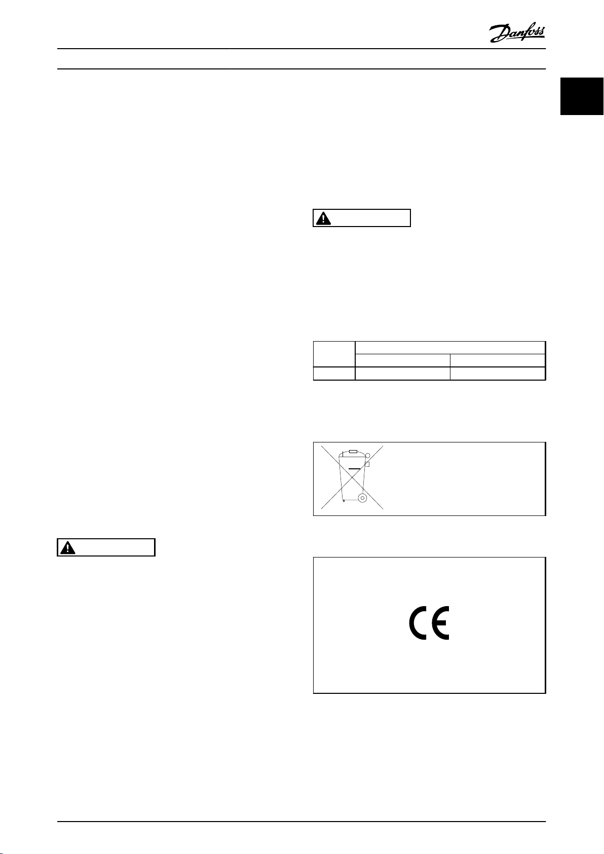
Disposal Instruction
1.3.1
1.4 Software Version
This Design Guide can be used for all FC 360 frequency
converters with software version 1.0x.
The software version number can be seen from 15-43 Software
Version.
Minimum waiting time [minutes]
4 15
Equipment containing electrical
components may not be disposed of
together with domestic waste.
It must be separately collected with
electrical and electronic waste according
to local and currently valid legislation.
Design Guide
Software version: 1.0x
1 1
MG06B202 - VLT® is a registered Danfoss trademark 9
Page 12

Introduction
VLT® AutomationDrive FC 360 Design Guide
11
1.5 CE Labelling
1.5.1 CE Conformity and Labelling
The machinery directive (2006/42/EC)
Frequency converters do not fall under the machinery
directive. However, if a frequency converter is supplied for
use in a machine, we provide information on safety
aspects relating to the frequency converter.
What is CE Conformity and Labelling?
The purpose of CE labelling is to avoid technical trade
obstacles within EFTA and the EU. The EU has introduced
the CE label as a simple way of showing whether a
product complies with the relevant EU directives. The CE
label says nothing about the specifications or quality of
the product. Frequency converters are regulated by two EU
directives:
The low-voltage directive (2006/95/EC)
Frequency converters must be CE labelled in accordance
with the low-voltage directive of January 1, 1997. The
directive applies to all electrical equipment and appliances
used in the 50-1000 V AC and the 75-1500 V DC voltage
ranges. Danfoss CE-labels in accordance with the directive
and issues a declaration of conformity upon request.
The EMC directive (2004/108/EC)
EMC is short for electromagnetic compatibility. The
presence of electromagnetic compatibility means that the
mutual interference between different components/
appliances does not affect the way the appliances work.
The EMC directive came into effect January 1, 1996.
Danfoss CE-labels in accordance with the directive and
issues a declaration of conformity upon request. To carry
out EMC-correct installation, see the instructions in this
Design Guide. In addition, we specify which standards our
products comply with.
1.5.3
CE labelling is a positive feature when used for its original
purpose, i.e. to facilitate trade within the EU and EFTA.
However, CE labelling may cover many different specifications. Thus, you have to check what a given CE label
specifically covers.
frequency converter must be CE labelled in
accordance with the EMC directive.
2. The frequency converter is sold for installation in
a plant. The plant is built up by professionals of
the trade. It could be a production plant or a
heating/ventilation plant designed and installed
by professionals of the trade. Neither the
frequency converter nor the finished plant has to
be CE labelled under the EMC directive. However,
the unit must comply with the basic EMC
requirements of the directive. This is ensured by
using components, appliances, and systems that
are CE labelled under the EMC directive.
3. The frequency converter is sold as part of a
complete system. The system is being marketed
as complete and could e.g. be an air-conditioning
system. The complete system must be CE labelled
in accordance with the EMC directive. The
manufacturer can ensure CE labelling under the
EMC directive either by using CE labelled
components or by testing the EMC of the system.
If he chooses to use only CE labelled
components, he does not have to test the entire
system.
Danfoss Frequency Converter and CE
Labelling
The frequency converter is most often used by professionals of the trade as a complex component forming part
of a larger appliance, system or installation. It must be
noted that the responsibility for the final EMC properties of
the appliance, system or installation rests with the installer.
What Is Covered
1.5.2
The EU "Guidelines on the Application of Council Directive
2004/108/EC" outline three typical situations of using a
frequency converter. See the following for EMC coverage
and CE labelling.
1. The frequency converter is sold directly to the
end-consumer. The frequency converter is for
example sold to a DIY market. The end-consumer
is a layman. He installs the frequency converter
himself for use with a hobby machine, a kitchen
appliance, etc. For such applications, the
10 MG06B202 - VLT® is a registered Danfoss trademark
The covered specifications can be very different and a CE
label may therefore give the installer a false feeling of
security when using a frequency converter as a component
in a system or an appliance.
Danfoss CE labels the frequency converters in accordance
with the low-voltage directive. This means that if the
frequency converter is installed correctly, we guarantee
compliance with the low-voltage directive. Danfoss issues a
declaration of conformity that confirms our CE labelling in
accordance with the low-voltage directive.
The CE label also applies to the EMC directive provided
that the instructions for EMC-correct installation and
filtering are followed. On this basis, a declaration of
conformity in accordance with the EMC directive is issued.
The Design Guide offers detailed instructions for installation to ensure EMC-correct installation. Furthermore,
Page 13

Introduction
VLT® AutomationDrive FC 360 Design Guide
Danfoss specifies which our different products comply
with.
Danfoss provides other types of assistance that can help
you obtain the best EMC result.
1.5.4 Compliance with EMC Directive
2004/108/EC
As mentioned, the frequency converter is mostly used by
professionals of the trade as a complex component
forming part of a larger appliance, system, or installation. It
must be noted that the responsibility for the final EMC
properties of the appliance, system or installation rests
with the installer. As an aid to the installer, Danfoss has
prepared EMC installation guidelines for the Power Drive
system. The standards and test levels stated for Power
Drive systems are complied with, provided that the EMCcorrect instructions for installation are followed, see
2.6.3 Immunity Requirements.
1.6 Air Humidity
The frequency converter has been designed to meet the
IEC/EN 60068-2-3 standard, EN 50178 pkt. 9.4.2.2 at 50 °C.
Aggressive Environments
1.6.1
A frequency converter contains a large number of
mechanical and electronic components. All are to some
extent vulnerable to environmental effects.
dust particles around the frequency converter fan. In very
dusty environments, use equipment with enclosure rating
IP54/55 or a cabinet for IP00/IP20/TYPE 1 equipment.
In environments with high temperatures and humidity,
corrosive gases such as sulphur, nitrogen, and chlorine
compounds will cause chemical processes on the
frequency converter components.
Chemical reactions will rapidly affect and damage the
electronic components. In such environments, mount the
equipment in a cabinet with fresh air ventilation, keeping
aggressive gases away from the frequency converter.
As an extra protection all printed circuit boards are coated
NOTE
Mounting frequency converters in aggressive environments
increases the risk of stoppages and considerably reduces
the life of the converter.
Before installing the frequency converter, check the
ambient air for liquids, particles, and gases. This is done by
observing existing installations in this environment. Typical
indicators of harmful airborne liquids are water or oil on
metal parts, or corrosion of metal parts.
Excessive dust particle levels are often found on installation cabinets and existing electrical installations. One
indicator of aggressive airborne gases is blackening of
copper rails and cable ends on existing installations.
Vibration and Shock
1.6.2
1 1
CAUTION
Frequency converters in environments with airborne
liquids, particles, or gases capable of affecting and
damaging the electronic components. Failure to take the
necessary protective measures increases the risk of
stoppages, thus reducing the life of the frequency
converter.
Degree of protection as per IEC 60529
Liquids can be carried through the air and condense in the
frequency converter and may cause corrosion of
components and metal parts. Steam, oil, and salt water
may cause corrosion of components and metal parts. In
such environments, use equipment with enclosure rating
IP54/55. As an extra protection, all printed circuit boards
are coated.
Airborne particles such as dust may cause mechanical,
electrical, or thermal failure in the frequency converter. A
typical indicator of excessive levels of airborne particles is
The frequency converter has been tested according to the
procedure based on the shown standards:
The frequency converter complies with requirements that
exist for units mounted on the walls and floors of
production premises, as well as in panels bolted to walls or
floors.
IEC/EN 60068-2-6: Vibration (sinusoidal) - 1970
•
IEC/EN 60068-2-64: Vibration, broad-band random
•
MG06B202 - VLT® is a registered Danfoss trademark 11
Page 14
130BA870.10
130BA809.10
130BA810.10
130BA810.10
130BA810.10
130BA826.10
130BA826.10
Product Overview
VLT® AutomationDrive FC 360 Design Guide
2 Product Overview
22
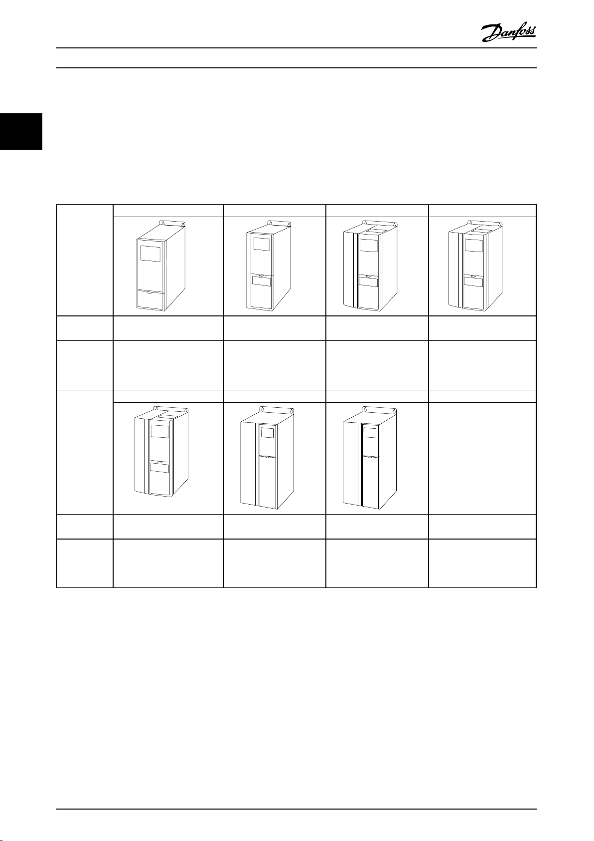
2.1 Enclosure Type Overview
Frame size depends on power range.
Frame size J1 J2 J3 J4
Enclosure
protection
High overload
rated power 160% overload
1)
torque
Frame size J5 J6 J7
Enclosure
protection
High overload
rated power 160% overload
torque
Table 2.1 Enclosure Types
1)
Sizes 11-75 kW also have normal overload: 110% overload
Sizes 11-22 kW high overload types: 150% overload
0.37-2.2 kW (380-480 V) 3.0-5.5 kW (380-480 V) 7.5 kW (380-480 V) 11-15 kW (380-480 V)
18.5-22 kW (380-480 V) 30-45 kW (380-480 V) 55-75 kW (380-480 V)
IP20 IP20 IP20 IP20
IP20 IP20 IP20
12 MG06B202 - VLT® is a registered Danfoss trademark
Page 15
130BC438.12
3 Phase
power
input
Switch Mode
Power Supply
Motor
Analog Output
Interface
(PNP) = Source
(NPN) = Sink
ON=Terminated
OFF=Open
Brake
resistor
91 (L1)
92 (L2)
93 (L3)
PE
50 (+10 V OUT)
53 (A IN)
54 (A IN)
55 (COM A IN)
0/4-20 mA
12 (+24 V OUT)
31 (D IN)
18 (D IN)
20 (COM D IN)
10 V DC
15 mA 100 mA
+ - + -
(U) 96
(V) 97
(W) 98
(PE) 99
(A OUT) 45
(A OUT) 42
(P RS-485) 68
(N RS-485) 69
(COM RS-485) 61
0V
5V
S801
0/4-20 mA
RS-485
RS-485
03
+10 V DC
0/4-20 mA
0-10 V DC
24 V DC
02
01
05
04
240 V AC, 2 A
24 V (NPN)
0 V (PNP)
0 V (PNP)
24 V (NPN)
19 (D IN)
24 V (NPN)
0 V (PNP)
27
24 V
0 V
(D IN/OUT)
0 V (PNP)
24 V (NPN)
(D IN/OUT)
0 V
24 V
29
24 V (NPN)
0 V (PNP)
0 V (PNP)
24 V (NPN)
33 (D IN)
32 (D IN)
95
P 5-00
21
ON
(+UDC) 82
(BR) 81
24 V (NPN)
0 V (PNP)
0-10 V DC
(-UDC) 88
RFI
3)
0 V
240 V AC, 2 A
Relay 1
1)
Relay 2 2)
4)
06
Product Overview
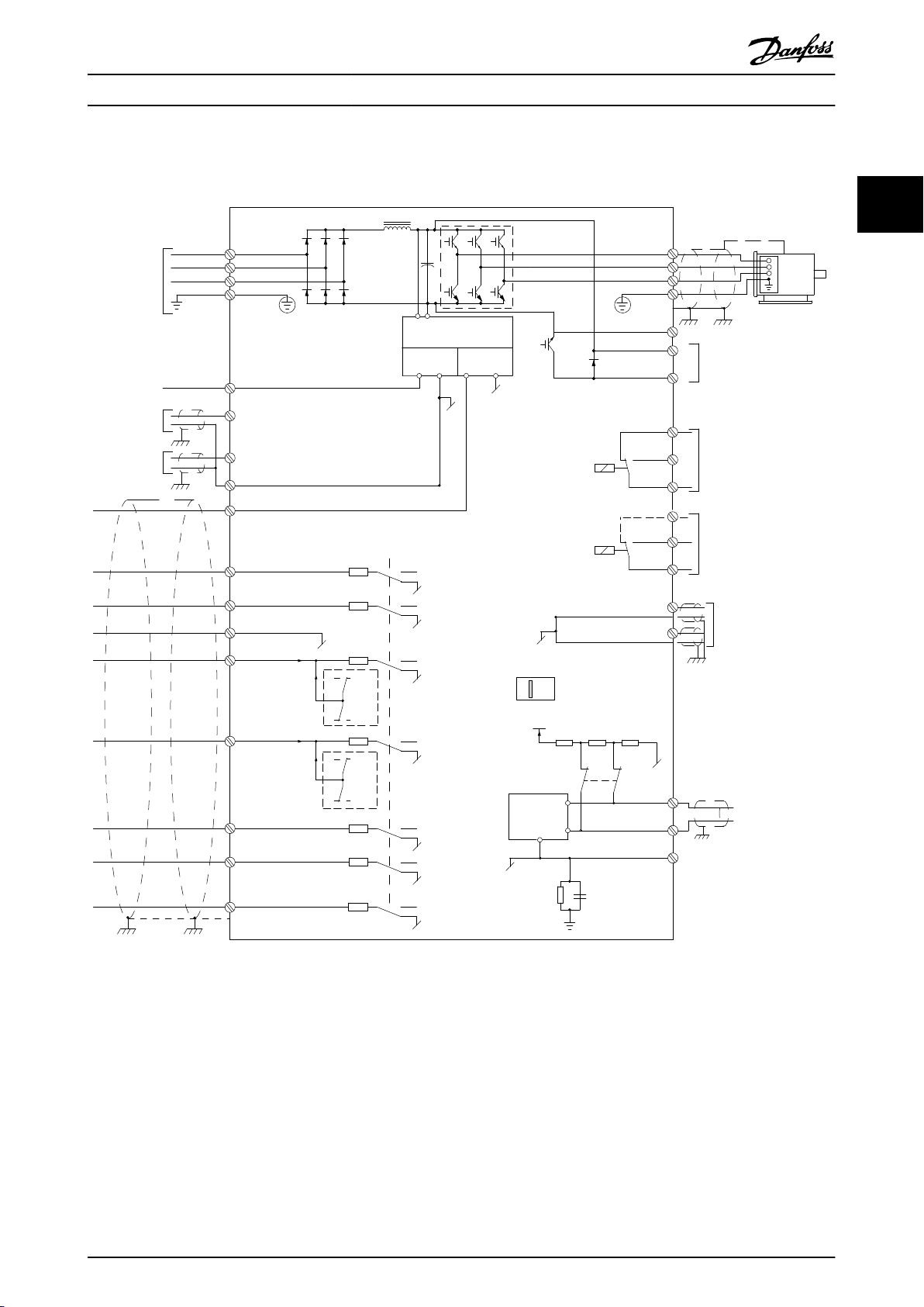
2.2 Electrical Installation
VLT® AutomationDrive FC 360 Design Guide
2 2
Illustration 2.1 Basic Wiring Schematic Drawing
A=Analog, D=Digital
1) Built-in brake chopper available from 0.37-22 kW
2) Relay 2 is 2 pole for J1-J3 and 3 pole for J4-J7. Relay 2 of J4-J7 with terminal 4, 5, 6, same NO/NC logic as Relay 1.
3) Dual DC choke in 30-75 kW
4) Switch S801 (bus terminal) can be used to enable termination on the RS-485 port (terminals 68 and 69).
MG06B202 - VLT® is a registered Danfoss trademark 13
Page 16

Product Overview
VLT® AutomationDrive FC 360 Design Guide
2.3 Control Structures
2.3.1 Control Principle
22
A frequency converter rectifies AC voltage from mains into
DC voltage, after which this DC voltage is converted into a
AC current with a variable amplitude and frequency.
The motor is supplied with variable voltage/current and
frequency, which enables infinitely variable speed control
of three-phased, standard AC motors and permanent
magnet synchronous motors.
FC 360 Controls
2.3.2
The frequency converter is capable of controlling either
the speed or the torque on the motor shaft. Setting
1-00 Configuration Mode determines the type of control.
Speed control
There are two types of speed control:
Speed closed loop PID control requires a speed
•
feedback to an input. A properly optimised speed
closed loop control will have higher accuracy
than a speed open loop control.
Selects which input to use as speed PID feedback in
7-00 Speed PID Feedback Source.
Torque control
The torque control function is used in applications where
the torque on motor output shaft is controlling the
application as tension control. Torque control can be
selected in 1-00 Configuration Mode. Torque setting is done
by setting an analog, digital or bus controlled reference.
When running torque control it is recommended to make
a full AMA procedure as the correct motor data are of high
importance for optimal performance.
Open loop in VVC
•
in mechanical robust applications, but the
accuracy is limited. Open loop torque function
works for two directions. The torque is calculated
on basic of current measurement internal in the
frequency converter. See Application Example
Torque open Loop
Speed/torque reference
The reference to these controls can either be a single
reference or be the sum of various references including
relatively scaled references. The handling of references is
explained in detail later in this section.
plus
mode. The function is used
14 MG06B202 - VLT® is a registered Danfoss trademark
Page 17

+
_
+
_
S
S
Cong. mode
Ref.
Process
P 1-00
High
+f max.
Low
-f max.
P 4-12
Motor speed
low limit (Hz)
P 4-14
Motor speed
high limit (Hz)
Motor
controller
Ramp
Speed
PID
P 7-20 Process feedback
1 source
P 7-22 Process feedback
2 source
P 7-00 Speed PID
feedback source
P 1-00
Cong. mode
P 4-19
Max. output freq.
-f max.
Motor
controller
P 4-19
Max. output freq.
+f max.
P 3-**
P 7-0*
130BD371.10
Product Overview
VLT® AutomationDrive FC 360 Design Guide
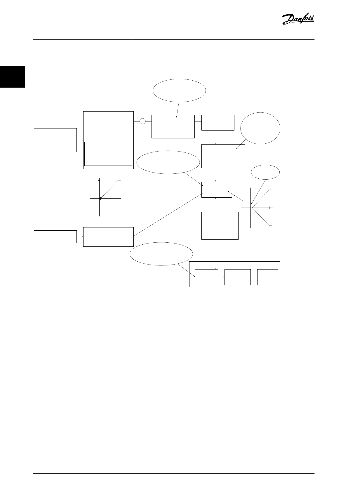
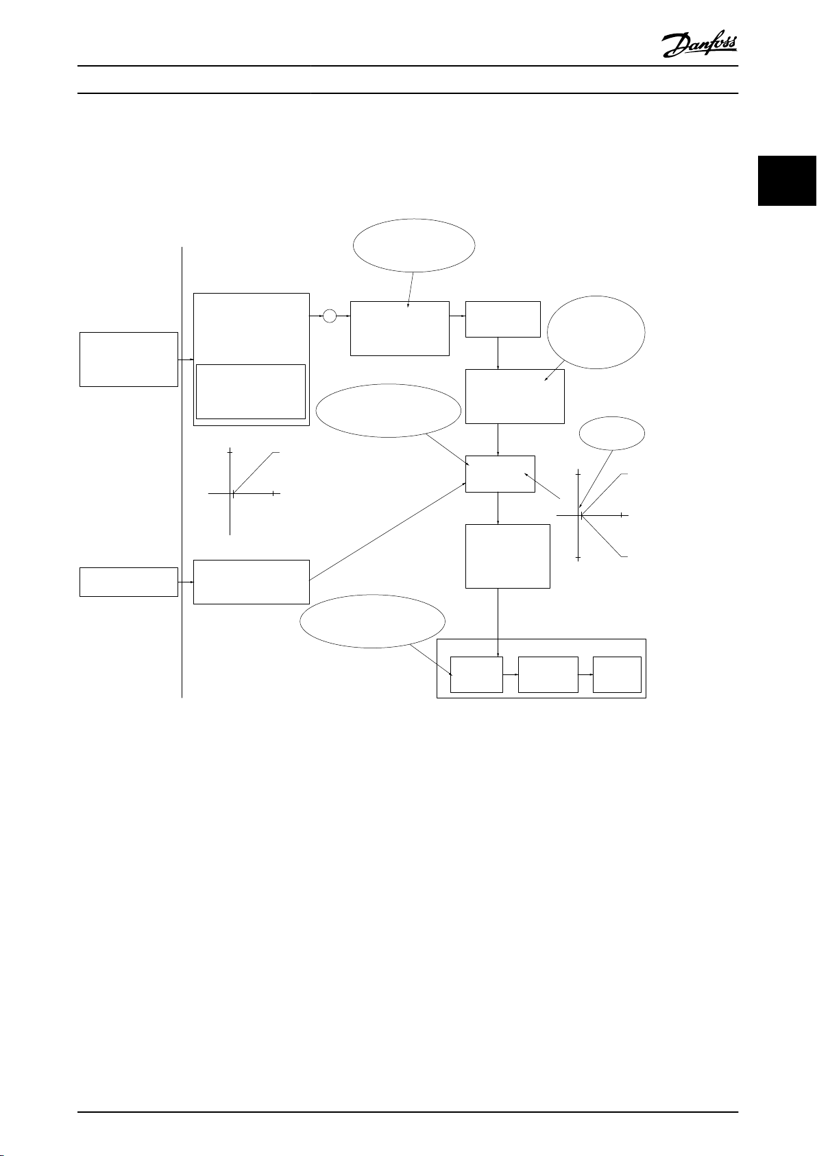
2.3.3
Control Structure in VVC
Illustration 2.2 Control Structure in VVC
In the configuration shown in Illustration 2.2, 1-01 Motor Control Principle is set to [1] VVC
plus
plus
Open Loop and Closed Loop Configurations
plus
and 1-00 Configuration Mode is
set to [0] Speed open loop. The resulting reference from the reference handling system is received and fed through the ramp
limitation and speed limitation before being sent to the motor control. The output of the motor control is then limited by
the maximum frequency limit.
2 2
If 1-00 Configuration Mode is set to [1] Speed closed loop the resulting reference will be passed from the ramp limitation and
speed limitation into a speed PID control. The Speed PID control parameters are located in the parameter group 7-0* Speed
PID Ctrl. The resulting reference from the Speed PID control is sent to the motor control limited by the frequency limit.
Select [3] Process in 1-00 Configuration Mode to use the process PID control for closed loop control of e.g. speed or pressure
in the controlled application. The Process PID parameters are located in parameter group 7-2* Process Ctrl. Feedb and 7-3*
Process PID Ctrl.
MG06B202 - VLT® is a registered Danfoss trademark 15
Page 18

Hand
On
Off
Reset
Auto
On
130BB893.10
Product Overview
VLT® AutomationDrive FC 360 Design Guide
2.3.4
Internal Current Control in VVC
plus
Mode
22
The frequency converter features an integral current limit
control which is activated when the motor current, and
thus the torque, is higher than the torque limits set in
4-16 Torque Limit Motor Mode, 4-17 Torque Limit Generator
Mode and 4-18 Current Limit.
When the frequency converter is at the current limit during
motor operation or regenerative operation, the frequency
converter will try to get below the preset torque limits as
quickly as possible without losing control of the motor.
Local (Hand On) and Remote (Auto
2.3.5
On) Control
Operate the frequency converter manually via the local
control panel (LCP) or remotely via analog/digital inputs or
serial bus.
Start and stop the frequency converter pressing the [Hand
On] and [Off/Reset] keys on the LCP. Setup required:
0-40 [Hand on] Key on LCP,
0-44 [Off/Reset] Key on LCP, and
0-42 [Auto on] Key on LCP.
Reset alarms via the [Off/Reset] key or via a digital input,
when the terminal is programmed to "Reset".
Illustration 2.3 LCP Control Keys
Local Reference forces the configuration mode to open
loop, independent of the setting of 1-00 Configuration
Mode.
Local Reference is restored at power-down.
16 MG06B202 - VLT® is a registered Danfoss trademark
Page 19
No function
Analog ref.
Pulse ref.
Local bus ref.
Preset relative ref.
Preset ref.
Local bus ref.
No function
Analog ref.
Pulse ref.
Analog ref.
Pulse ref.
Local bus ref.
No function
Local bus ref.
Pulse ref.
No function
Analog ref.
Input command:
Catch up/ slow down
Catchup Slowdown
value
Freeze ref./Freeze output
Speed up/ speed down
ref.
Remote
Ref. in %
-max ref./
+max ref.
Scale to
Hz
Scale to
Nm
Scale to
process
unit
Relative
X+X*Y
/100
DigiPot
DigiPot
DigiPot
max ref.
min ref.
DigiPot
D1
P 5-1x(15)
Preset '1'
External '0'
Process
Torque
Speed
open/closed loop
(1)
(2)
(3)
(4)
(5)
(6)
(7)
(0)
(0)
(1)
Relative scaling ref.
P 3-18
Ref.resource 1
P 3-15
Ref. resource 2
P 3-16
Ref. resource 3
P 3-17
200%
-200%
Y
X
-100%
100%
%
%
Ref./feedback range
P 3-00
Conguration mode
P 1-00
P 3-14
±100%
130BD374.10
P 16-01
P 16-02
P 3-12
P 5-1x(21)/P 5-1x(22)
P 5-1x(28)/P 5-1x(29)
P 5-1x(19)/P 5-1x(20)
P 3-04
Freeze ref.
&
increase/
decrease
ref.
Catch up/
slow
down
P 3-10
Product Overview
VLT® AutomationDrive FC 360 Design Guide
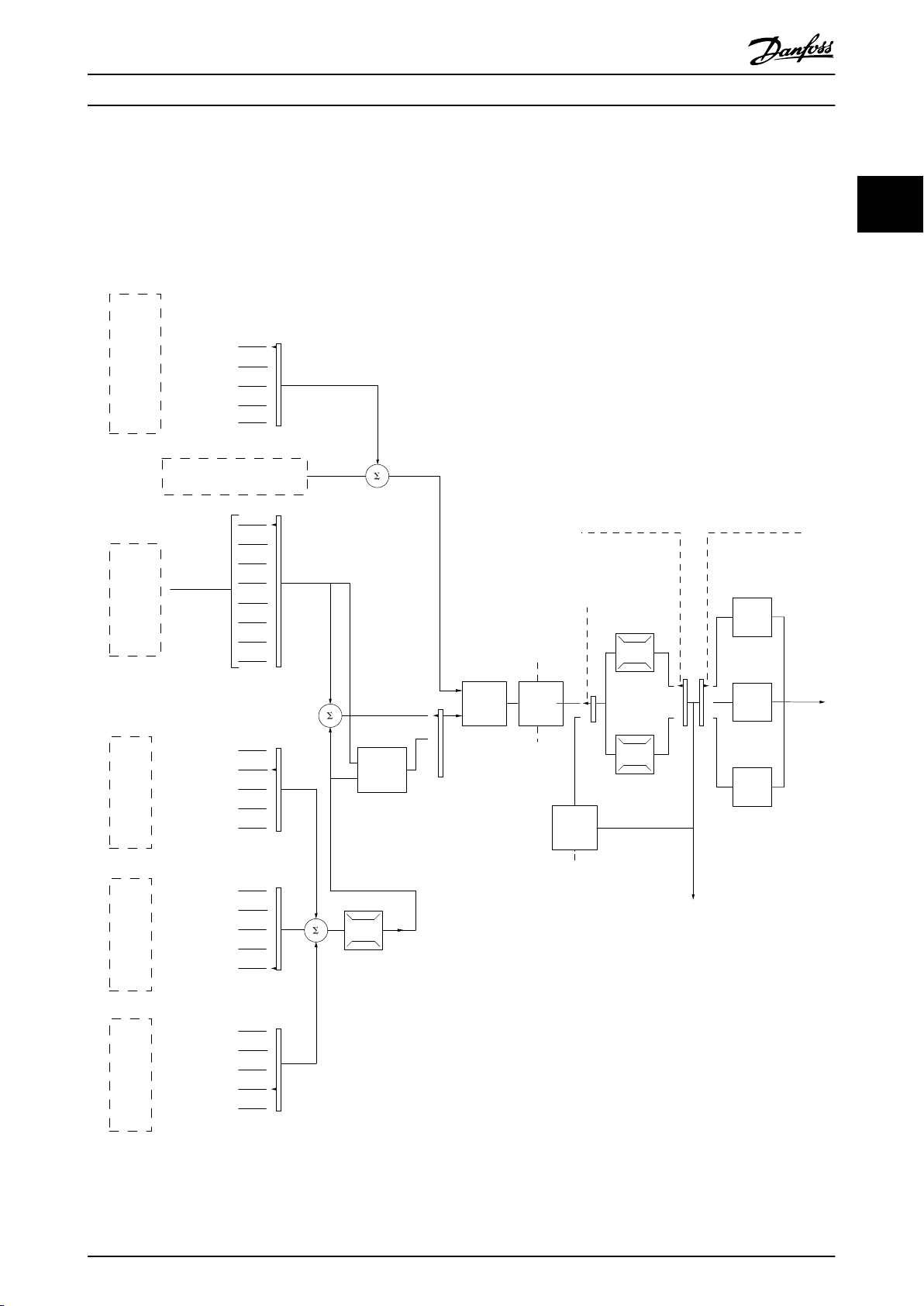
2.4 Reference Handling
Local reference
The local reference is active when the frequency converter is operated with [Hand On] active. Adjust the reference by
[▲]/[▼] and [◄/[►].
Remote reference
The reference handling system for calculating the Remote reference is shown in Illustration 2.4.
2 2
Illustration 2.4 Remote Reference
MG06B202 - VLT® is a registered Danfoss trademark 17
Page 20
Resulting reference
Sum of all
references
Forward
Reverse
P 3-00 Reference Range= [0] Min-Max
130BA184.10
-P 3-03
P 3-03
P 3-02
-P 3-02
P 3-00 Reference Range =[1]-Max-Max
Resulting reference
Sum of all
references
-P 3-03
P 3-03
130BA185.10
130BA186.11
P 3-03
P 3-02
Sum of all
references
P 3-00 Reference Range= [0] Min to Max
Resulting reference
Product Overview
VLT® AutomationDrive FC 360 Design Guide
The remote reference is calculated once every scan
interval and initially consists of two types of reference
inputs:
22
1. X (the external reference): A sum (see
3-04 Reference Function) of up to 4 externally
selected references, comprising any combination
(determined by the setting of 3-15 Reference 1
Source, 3-16 Reference 2 Source and 3-17 Reference
3 Source) of a fixed preset reference (3-10 Preset
Reference), variable analog references, variable
digital pulse references, and various serial bus
references in whatever unit the frequency
converter is controlled ([Hz], [RPM], [Nm] etc.).
2. Y- (the relative reference): A sum of one fixed
preset reference (3-14 Preset Relative Reference)
and one variable analog reference (3-18 Relative
Scaling Reference Source) in [%].
Illustration 2.5 Sum of all References
The two types of reference inputs are combined in the
following formula: Remote reference = X + X * Y / 100%. If
relative reference is not used, set 3-18 Relative Scaling
Reference Source to [0] No function and 3-14 Preset Relative
Reference to 0%. The catch up/slow down function and the
freeze reference function can both be activated by digital
inputs on the frequency converter. The functions and
parameters are described in the VLT® AutomationDrive FC
360 Programming Guide.
The scaling of analog references are described in
parameter groups 6-1* Analog Input 53 and 6-2* Analog
Input 54, and the scaling of digital pulse references are
described in parameter group 5-5* Pulse Input.
Reference limits and ranges are set in parameter group
3-0* Reference Limits.
Illustration 2.6 Sum of all References
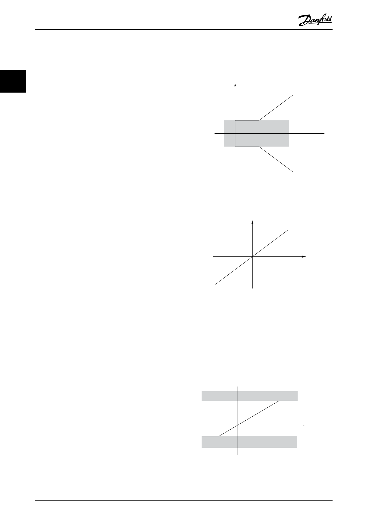
Reference Limits
2.4.1
3-00 Reference Range, 3-02 Minimum Reference and
3-03 Maximum Reference together define the allowed range
of the sum of all references. The sum of all references are
clamped when necessary. The relation between the
resulting reference (after clamping) and the sum of all
references is shown in Illustration 2.5 and Illustration 2.6.
18 MG06B202 - VLT® is a registered Danfoss trademark
The value of 3-02 Minimum Reference cannot be set to less
than 0, unless 1-00 Configuration Mode is set to [3] Process.
In that case, the following relations between the resulting
reference (after clamping) and the sum of all references is
as shown in Illustration 2.7.
Illustration 2.7 Sum of all References
Page 21

Resource output
[Hz]
Resource input
Terminal X
high
High reference/
feedback value
130BD431.10
8
[V]
50
10
P1
P2
10
Low reference/
feedback value
Product Overview
VLT® AutomationDrive FC 360 Design Guide
2.4.2 Scaling of Preset References and Bus
References
Preset references are scaled according to the following
rules:
When 3-00 Reference Range: [0] Min - Max 0%
•
reference equals 0 [unit] where unit can be any
unit e.g. rpm, m/s, bar etc. 100% reference equals
the Max (abs (3-03 Maximum Reference), abs
(3-02 Minimum Reference).
When 3-00 Reference Range: [1] -Max - +Max 0%
•
reference equals 0 [unit] -100% reference equals Max Reference 100% reference equals Max
Reference.
Bus references are scaled according to the following rules:
When 3-00 Reference Range: [0] Min - Max. To
•
obtain max resolution on the bus reference the
scaling on the bus is: 0% reference equals Min
Reference and 100% reference equals Max
reference.
When 3-00 Reference Range: [1] -Max - +Max
•
-100% reference equals -Max Reference 100%
reference equals Max Reference.
Scaling of Analog and Pulse
2.4.3
References and Feedback
2 2
References and feedback are scaled from analog and pulse
inputs in the same way. The only difference is that a
reference above or below the specified minimum and
maximum “endpoints” (P1 and P2 in Illustration 2.8) are
clamped whereas a feedback above or below is not.
Illustration 2.8 Minimum and Maximum Endpoints
MG06B202 - VLT® is a registered Danfoss trademark 19
Page 22

Product Overview
VLT® AutomationDrive FC 360 Design Guide
The endpoints P1 and P2 are defined by the following parameters depending on choice of input.
22
voltage
mode
P1 = (Minimum input value, Minimum reference value)
Minimum reference value 6-14 Terminal
53 Low Ref./
Feedb. Value
Minimum input value 6-10 Terminal
53 Low
Voltage [V]
P2 = (Maximum input value, Maximum reference value)
Maximum reference value 6-15 Terminal
53 High Ref./
Feedb. Value
Maximum input value 6-11 Terminal
53 High
Voltage [V]
Table 2.2 P1 and P2 Endpoints
Input Analog 53
Analog 53
current mode
6-14 Terminal 53
Low Ref./Feedb.
Value
6-12 Terminal 53
Low Current
[mA]
6-15 Terminal 53
High Ref./Feedb.
Value
6-13 Terminal 53
High Current
[mA]
Analog 54
voltage
mode
6-24 Terminal
54 Low Ref./
Feedb. Value
6-20 Terminal
54 Low
Voltage [V]
6-25 Terminal
54 High Ref./
Feedb. Value
6-21 Terminal
54 High
Voltage[V]
Analog 54
current mode
6-24 Terminal 54
Low Ref./Feedb.
Value
6-22 Terminal 54
Low Current
[mA]
6-25 Terminal 54
High Ref./Feedb.
Value
6-23 Terminal 54
High Current
[mA]
Pulse Input 29 Pulse Input 33
5-52 Term. 29
Low Ref./Feedb.
Value
5-50 Term. 29
Low Frequency
[Hz]
5-53 Term. 29
High Ref./
Feedb. Value
5-51 Term. 29
High Frequency
[Hz]
5-57 Term. 33 Low
Ref./Feedb. Value
5-55 Term. 33 Low
Frequency [Hz]
5-58 Term. 33 High
Ref./Feedb. Value
5-56 Term. 33 High
Frequency [Hz]
20 MG06B202 - VLT® is a registered Danfoss trademark
Page 23

Resource output
[Hz] or “No unit”
Resource input
[mA]
Quadrant 2
Quadrant 3
Quadrant 1
Quadrant 4
Terminal X high
Low reference/feedback
value
High reference/feedback
value
1
-50
165020
P1
P2
0
130BD446.10
forward
reverse
Terminal low
Product Overview
2.4.4 Dead Band Around Zero
VLT® AutomationDrive FC 360 Design Guide
In some cases the reference (in rare cases also the
feedback) should have a dead band around zero (i.e. to
make sure the machine is stopped when the reference is
“near zero”).
To make the dead band active and to set the amount of
dead band, the following settings must be done:
Either minimum reference value (see Table 2.2 for
•
relevant parameter) or maximum reference value
must be zero. In other words; Either P1 or P2
must be on the X-axis in Illustration 2.9.
And both points defining the scaling graph are in
•
the same quadrant.
The size of the Dead Band is defined by either P1 or P2 as
shown in Illustration 2.9.
2 2
Illustration 2.9 Size of Dead Band
MG06B202 - VLT® is a registered Danfoss trademark 21
Page 24
20
1
10
V
V
20
1
10
-20
130BD454.10
+
Analog input 53
Low reference 0 Hz
High reference 20 Hz
Low voltage 1 V
High voltage 10 V
Ext. source 1
Range:
0.0% (0 Hz)
100.0% (20 Hz)
100.0% (20 Hz)
Ext. reference
Range:
0.0% (0 Hz)
20 Hz 10V
Ext. Reference
Absolute
0 Hz 1 V
Reference
algorithm
Reference
100.0% (20 Hz)
0.0% (0 Hz)
Range:
Limited to:
0%- +100%
(0 Hz- +20 Hz)
Limited to: -200%- +200%
(-40 Hz- +40 Hz)
Reference is scaled
according to min
max reference giving a
speed.!!!
Scale to
speed
+20 Hz
-20 Hz
Range:
Speed
setpoint
Motor
control
Range:
-8 Hz
+8 Hz
Motor
Digital input 19
Low No reversing
High Reversing
Limits Speed Setpoint
according to min max speed.!!!
Motor PID
Hz
Hz
Dead band
Digital input
General Reference
parameters:
Reference Range: Min - Max
Minimum Reference: 0 Hz (0,0%)
Maximum Reference: 20 Hz (100,0%)
General Motor
parameters:
Motor speed direction:Both directions
Motor speed Low limit: 0 Hz
Motor speed high limit: 8 Hz
Product Overview
VLT® AutomationDrive FC 360 Design Guide
Case 1: Positive reference with dead band, digital input to trigger reverse
Illustration 2.10 shows how reference input with limits inside Min to Max limits clamps.
22
Illustration 2.10 Clamping of Reference Input with Limits inside Min to Max
22 MG06B202 - VLT® is a registered Danfoss trademark
Page 25
+
30 Hz
1
10
20 Hz
1
10
130BD433.10
-20 Hz
V
V
Analog input 53
Low reference 0 Hz
High reference 20 Hz
Low voltage 1 V
High voltage 10 V
Ext. source 1
Range:
0.0% (0 Hz)
150.0% (30 Hz)
150.0% (30 Hz)
Ext. reference
Range:
0.0% (0 Hz)
30 Hz 10 V
Ext. Reference
Absolute
0 Hz 1 V
Reference
algorithm
Reference
100.0% (20 Hz)
0.0% (0 Hz)
Range:
Limited to:
-100%- +100%
(-20 Hz- +20 Hz)
Limited to: -200%- +200%
(-40 Hz- +40 Hz)
Reference is scaled
according to
max reference giving a
speed.!!!
Scale to
speed
+20 Hz
-20 Hz
Range:
Speed
setpoint
Motor
control
Range:
-8 Hz
+8 Hz
Motor
Digital input 19
Low No reversing
High Reversing
Limits Speed Setpoint
according to min max speed.!!!
Motor PID
Dead band
Digital input
General Reference
parameters:
Reference Range: -Max - Max
Minimum Reference: Don't care
Maximum Reference: 20 Hz (100.0%)
General Motor
parameters:
Motor speed direction: Both directions
Motor speed Low limit: 0 Hz
Motor speed high limit: 10 Hz
Product Overview
VLT® AutomationDrive FC 360 Design Guide
Case 2: Positive reference with dead band, digital input to trigger reverse. Clamping rules.
Illustration 2.11 shows how reference input with limits outside -Max to +Max limits clamps to the inputs low and high limits
before addition to external reference. And how the external reference is clamped to -Max to +Max by the Reference
algorithm.
2 2
Illustration 2.11 Clamping of Reference Input with Limits outside -Min to +Max
MG06B202 - VLT® is a registered Danfoss trademark 23
Page 26

Product Overview
VLT® AutomationDrive FC 360 Design Guide
2.5 PID Control
2.5.1 Speed PID Control
22
1-00 Configuration Mode
[0] Speed open loop Not Active Not Active
[1] Speed closed loop N.A. ACTIVE
[2] Torque N.A. Not Active
[3] Process Not Active Not Active
Table 2.3 Control Configurations, Active Speed Control
“N.A.” means that the specific mode is not available at all. “Not Active” means that the specific mode is available but the Speed Control is not
active in that mode.
The following parameters are relevant for the Speed Control:
Parameter Description of function
7-00 Speed PID Feedback Source Select from which input the Speed PID should get its feedback.
7-02 Speed PID Proportional Gain The higher the value - the quicker the control. However, too high value may lead to oscillations.
7-03 Speed PID Integral Time Eliminates steady state speed error. Lower value means quicker reaction. However, too low value may
lead to oscillations.
7-04 Speed PID Differentiation
Time
7-05 Speed PID Diff. Gain Limit If there are quick changes in reference or feedback in a given application - which means that the error
7-06 Speed PID Lowpass Filter
Time
Provides a gain proportional to the rate of change of the feedback. A setting of zero disables the
differentiator.
changes swiftly - the differentiator may soon become too dominant. This is because it reacts to
changes in the error. The quicker the error changes, the stronger the differentiator gain is. The differ-
entiator gain can thus be limited to allow setting of the reasonable differentiation time for slow
changes and a suitably quick gain for quick changes.
A low-pass filter that dampens oscillations on the feedback signal and improves steady state
performance. However, too large filter time will deteriorate the dynamic performance of the Speed PID
control.
Practical settings of parameter 7-06 taken from the number of pulses per revolution on from encoder
(PPR):
Encoder PPR 7-06 Speed PID Lowpass Filter
512 10 ms
1024 5 ms
2048 2 ms
4096 1 ms
1-01 Motor Control Principle
U/f
Time
VVC
plus
Table 2.4 Speed Control Parameters
24 MG06B202 - VLT® is a registered Danfoss trademark
Page 27

M
3
96 97 9998
91 92 93 95
50
12
L1 L2L1PEL3
W PEVU
F1
L2
L3
N
PE
18
53
27
55
20
32
33
24 Vdc
130BD372.10
Product Overview
VLT® AutomationDrive FC 360 Design Guide
Example of how to Programme the Speed Control
In this case, the Speed PID Control is used to maintain a
constant motor speed regardless of the changing load on
the motor. The required motor speed is set via a potentiometer connected to terminal 53. The speed range is
0-1500 RPM corresponding to 0-10 V over the potentiometer. Starting and stopping is controlled by a switch
connected to terminal 18. The Speed PID monitors the
actual RPM of the motor by using a 24 V (HTL) incremental
encoder as feedback. The feedback sensor is an encoder
(1024 pulses per revolution) connected to terminals 32 and
33. The pulse frequency range to terminals 32 and 33 is 4
Hz-32 kHz
2 2
Illustration 2.12 Speed Control Programming
MG06B202 - VLT® is a registered Danfoss trademark 25
Page 28

Product Overview
VLT® AutomationDrive FC 360 Design Guide
The following must be programmed in order shown (see explanation of settings in the VLT® AutomationDrive FC 360
Programming Guide)
In Table 2.5 it is assumed that all other parameters and switches remain at their default setting.
22
Function Parameter no. Setting
1) Make sure the motor runs properly. Do the following:
Set the motor parameters using name plate data 1-2* As specified by motor name plate
Have the frequency converter makes an Automatic Motor
Adaptation
2) Check the motor is running and the encoder is attached properly. Do the following:
Press [Hand On]. Check that the motor is running and note
in which direction it is turning (henceforth referred to as
the “positive direction”).
3) Make sure the drive limits are set to safe values
Set acceptable limits for the references. 3-02 Minimum Reference
Check that the ramp settings are within drive capabilities
and allowed application operating specifications.
Set acceptable limits for the motor speed and frequency. 4-12 Motor Speed Low
4) Configure the Speed Control and select the Motor Control principle
Activation of Speed Control 1-00 Configuration Mode [1] Speed closed loop
Selection of Motor Control Principle 1-01 Motor Control
5) Configure and scale the reference to the Speed Control
Set up Analog Input 53 as a reference Source 3-15 Reference Resource1Not necessary (default)
1-29 Automatic Motor
Adaptation (AMA)
Set a positive reference.
3-03 Maximum Reference050
3-41 Ramp 1 Ramp Up
Time
3-42 Ramp 1 Ramp Down
Time
Limit [Hz]
4-14 Motor Speed High
Limit [Hz]
4-19 Max Output
Frequency
Principle
[1] Enable complete AMA
default setting
default setting
0 Hz
50 Hz
60 Hz
plus
[1] VVC
Scale Analog Input 53 0 RPM (0 V) to 50 RPM (10 V) 6-1* Not necessary (default)
6) Configure the 24 V HTL encoder signal as feedback for the Motor Control and the Speed Control
Set up digital input 32 and 33 as encoder inputs 5-14 Terminal 32 Digital
Input
5-15 Terminal 33 Digital
Input
Choose terminal 32/33 as Speed PID feedback 7-00 Speed PID Feedback
Source
7) Tune the Speed Control PID parameters
Use the tuning guidelines when relevant or tune manually 7-0* See the guidelines below
8) Finished!
Save the parameter setting to the LCP for safe keeping 0-50 LCP Copy [1] All to LCP
Table 2.5 Programming Order for Speed PID Control
[82] Encoder input B
[83] Encoder input A
[1] 24 V Encoder
26 MG06B202 - VLT® is a registered Danfoss trademark
Page 29

P 7-30
normal/inverse
PID
P 7-38
*(-1)
Feed forward
Ref.
Handling
Feedback
Handling
% [unit]
% [unit]
%
[unit]
%
[speed]
Scale to
speed
P 4-10
Motor speed
direction
To motor
control
Process PID
130BA178.10
_
+
0%
-100%
100%
0%
-100%
100%
Product Overview
2.5.2 Process PID Control
VLT® AutomationDrive FC 360 Design Guide
The Process PID Control can be used to control application parameters that can be measured by a sensor (i.e. pressure,
temperature, flow) and be affected by the connected motor through a pump, fan or otherwise.
Table 2.6 shows the control configurations where the Process Control is possible. Refer to 2.3 Control Structures to see where
the Speed Control is active.
1-00 Configuration Mode 1-01 Motor Control Principle
U/f
VVC
plus
[3] Process N.A. Process
Table 2.6 Control Configuration
NOTE
The Process Control PID will work under the default parameter setting, but tuning the parameters is highly recommended
to optimise the application control performance.
2 2
Illustration 2.13 Process PID Control Diagram
MG06B202 - VLT® is a registered Danfoss trademark 27
Page 30

Product Overview
VLT® AutomationDrive FC 360 Design Guide
2.5.3 Process Control Relevant Parameters
22
Parameter Description of function
7-20 Process CL Feedback 1 Resource Select from which Source (i.e. analog or pulse input) the Process PID should get its
feedback
7-22 Process CL Feedback 2 Resource Optional: Determine if (and from where) the Process PID should get an additional
feedback signal. If an additional feedback source is selected the two feedback signals will
be added together before being used in the Process PID Control.
7-30 Process PID Normal/ Inverse Control
7-31 Process PID Anti Windup The anti windup function ensures that when either a frequency limit or a torque limit is
7-32 Process PID Start Speed In some applications, reaching the required speed/set point can take a very long time. In
7-33 Process PID Proportional Gain The higher the value, the quicker the control. However, too large value may lead to
7-34 Process PID Integral Time Eliminates steady state speed error. Lower value means quick reaction. However, too small
7-35 Process PID Differentiation Time Provides a gain proportional to the rate of change of the feedback. A setting of zero
7-36 Process PID Diff. Gain Limit If there are quick changes in reference or feedback in a given application - which means
7-38 Process PID Feed Forward Factor In application where there is a good (and approximately linear) correlation between the
5-54 Pulse Filter Time Constant #29 (Pulse
term. 29), 5-59 Pulse Filter Time Constant #33
(Pulse term. 33), 6-16 Terminal 53 Filter Time
Constant (Analog term 53), 6-26 Terminal 54
Filter Time Constant (Analog term. 54)
Under [0] Normal operation the Process Control will respond with an increase of the motor
speed if the feedback is getting lower than the reference. In the same situation, but under
[1] Inverse operation, the Process Control will respond with a decreasing motor speed
instead.
reached, the integrator will be set to a gain that corresponds to the actual frequency. This
avoids integrating on an error that cannot in any case be compensated for by means of a
speed change. This function can be disabled by selecting [0] Off.
such applications it might be an advantage to set a fixed motor speed from the frequency
converter before the process control is activated. This is done by setting a Process PID
Start Value (speed) in 7-32 Process PID Start Speed.
oscillations.
value may lead to oscillations.
disables the differentiator.
that the error changes swiftly - the differentiator may soon become too dominant. This is
because it reacts to changes in the error. The quicker the error changes, the stronger the
differentiator gain is. The differentiator gain can thus be limited to allow setting of the
reasonable differentiation time for slow changes.
process reference and the motor speed necessary for obtaining that reference, the Feed
Forward Factor can be used to achieve better dynamic performance of the Process PID
Control.
If there are oscillations of the current/voltage feedback signal, these can be dampened by
means of a low-pass filter. This time constant represents the speed limit of the ripples
occurring on the feedback signal.
Example: If the low-pass filter has been set to 0.1 s, the limit speed will be 10 RAD/s (the
reciprocal of 0.1 s), corresponding to (10/(2 x π)) = 1.6 Hz. This means that all currents/
voltages that vary by more than 1.6 oscillations per second will be damped by the filter.
The control will only be carried out on a feedback signal that varies by a frequency
(speed) of less than 1.6 Hz.
The low-pass filter improves steady state performance but selecting a too large filter time
will deteriorate the dynamic performance of the Process PID Control.
Table 2.7 Process Control Parameters
28 MG06B202 - VLT® is a registered Danfoss trademark
Page 31

Temperature
Fan speed
Temperature
transmitter
Heat
Heat
generating
process
Cold air
130BA218.10
100kW
n °CW
Transmitter
96 97 9998
91 92 93 95
50
12
L1 L2L1PEL3
W PEVU
F1
L2
L3
N
PE
130BD373.10
18
53
27
55
54
M
3
Product Overview
VLT® AutomationDrive FC 360 Design Guide
2.5.4 Example of Process PID Control
Illustration 2.14 is an example of a Process PID Control
used in a ventilation system:
Illustration 2.14 Process PID Control in a Ventilation System
In a ventilation system, the temperature is to be settable
from - 5 to 35 °C with a potentiometer of 0-10 V. The set
temperature must be kept constant, for which purpose the
Process Control is to be used.
The control is of the inverse type, which means that when
the temperature increases, the ventilation speed is
increased as well, so as to generate more air. When the
temperature drops, the speed is reduced. The transmitter
used is a temperature sensor with a working range of -10
to 40 °C, 4-20 mA. Min./Max. speed 300/1500 RPM.
2 2
Illustration 2.15 Two-wire Transmitter
1. Start/Stop via switch connected to terminal 18.
2. Temperature reference via potentiometer (-5 to
35 °C, 0-10 V DC) connected to terminal 53.
3. Temperature feedback via transmitter (-10 to 40
°C, 4-20 mA) connected to terminal 54.
MG06B202 - VLT® is a registered Danfoss trademark 29
Page 32

Product Overview
VLT® AutomationDrive FC 360 Design Guide
Function Par. no. Setting
Initialize the frequency converter 14-22 [2] Initialization - make a power cycling - press reset
1) Set motor parameters:
22
Set the motor parameters according to name plate
1-2* As stated on motor name plate
data
Perform a full Automation Motor Adaptation 1-29 [1] Enable complete AMA
2) Check that motor is running in the right direction.
When motor is connected to frequency converter with straight forward phase order as U - U; V- V; W - W motor shaft usually turns
clockwise seen into shaft end.
Press [Hand On]. Check shaft direction by applying
a manual reference.
If motor turns opposite of required direction:
1.
Change motor direction in 4-10 Motor Speed
4-10 Select correct motor shaft direction
Direction
2. Turn off mains - wait for DC link to discharge switch two of the motor phases
Set configuration mode 1-00 [3] Process
3) Set reference configuration, ie. the range for reference handling. Set scaling of analog input in parameter 6-xx
Set reference/feedback units
Set min. reference (10 °C)
Set max. reference (80 °C)
If set value is determined from a preset value
(array parameter), set other reference sources to
No Function
3-01
3-02
3-03
3-10
[60] ° C Unit shown on display
-5° C
35° C
[0] 35%
Par
. 3 − 10
(0)
Ref
=
100
×
((
Par
. 3 − 03) −
(
par
. 3 − 02)) = 24, 5°
C
3-14 Preset Relative Reference to 3-18 Relative Scaling Reference Resource [0]
= No Function
4) Adjust limits for the frequency converter:
Set ramp times to an appropriate value as 20 s 3-41
3-42
Set min. speed limits
Set motor speed max. limit
Set max. output frequency
4-12
4-14
4-19
20 s
20 s
10 Hz
50 Hz
60 Hz
Set 6-19 Terminal 53 mode and 6-29 Terminal 54 mode to voltage or current mode.
5) Scale analog inputs used for reference and feedback
Set terminal 53 low voltage
Set terminal 53 high voltage
Set terminal 54 low feedback value
Set terminal 54 high feedback value
Set feedback source
6-10
6-11
6-24
6-25
7-20
0V
10V
-5° C
35° C
[2] Analog input 54
6) Basic PID settings
Process PID Normal/Inverse 7-30 [0] Normal
Process PID Anti Wind-up 7-31 [1] On
Process PID start speed 7-32 300 rpm
Save parameters to LCP 0-50 [1] All to LCP
Table 2.8 Example of Process PID Control Set-up
30 MG06B202 - VLT® is a registered Danfoss trademark
Page 33

130BA183.10
y(t)
t
P
u
Product Overview
VLT® AutomationDrive FC 360 Design Guide
2.5.5 Optimisation of the Process Regulator
The basic settings have now been made; all that needs to
be done is to optimise the proportional gain, the
integration time and the differentiation time (7-33 Process
PID Proportional Gain, 7-34 Process PID Integral Time,
7-35 Process PID Differentiation Time). In most processes,
this can be done by following this procedure:
1. Start the motor
2.
Set 7-33 Process PID Proportional Gain to 0.3 and
increase it until the feedback signal again begins
to vary continuously. Then reduce the value until
the feedback signal has stabilised. Now lower the
proportional gain by 40-60%.
3.
Set 7-34 Process PID Integral Time to 20 s and
reduce the value until the feedback signal again
begins to vary continuously. Increase the
integration time until the feedback signal
stabilises, followed by an increase of 15-50%.
4.
Only use 7-35 Process PID Differentiation Time for
very fast-acting systems only (differentiation
time). The typical value is four times the set
integration time. The differentiator should only be
used when the setting of the proportional gain
and the integration time has been fully
optimised. Make sure that oscillations on the
feedback signal is sufficiently dampened by the
lowpass filter on the feedback signal.
should be measured when the amplitude of oscillation is
quite small.
1. Select only proportional control, meaning that
the integral time is set to the maximum value,
while the differentiation time is set to 0.
2. Increase the value of the proportional gain until
the point of instability is reached (sustained
oscillations) and the critical value of gain, Ku, is
reached.
3. Measure the period of oscillation to obtain the
critical time constant, Pu.
4.
Use Table 2.9 to calculate the necessary PID
control parameters.
The process operator can do the final tuning of the control
iteratively to yield satisfactory control.
2 2
NOTE
If necessary, start/stop can be activated a number of times
in order to provoke a variation of the feedback signal.
2.5.6 Ziegler Nichols Tuning Method
To tune the PID controls of the frequency converter,
several tuning methods can be used. Danfoss recommends
to use the Ziegler Nichols tuning method.
NOTE
Do not use the Ziegler Nichols Tuning method in
applications that could be damaged by the oscillations
created by marginally stable control settings.
The criteria for adjusting the parameters are based on
evaluating the system at the limit of stability rather than
on taking a step response. Increase the proportional gain
until observing continuous oscillations (as measured on
the feedback), that is, until the system becomes marginally
stable. The corresponding gain (Ku) is called the ultimate
gain, and is the gain at which the oscillation is obtained.
The period of the oscillation (Pu) (called the ultimate
period) is determined as shown in Illustration 2.16 and
Illustration 2.16 Marginally Stable System
Type of
Control
PI-control
PID tight
control
PID some
overshoot
Table 2.9 Ziegler Nichols Tuning for Regulator
Proportional
Gain
0.45 * K
u
0.6 * K
u
0.33 * K
u
Integral Time Differentiation
0.833 * P
0.5 * P
0.5 * P
u
u
u
Time
-
0.125 * P
0.33 * P
u
u
MG06B202 - VLT® is a registered Danfoss trademark 31
Page 34

1
2
z
z
z
L1
L2
L3
PE
U
V
W
C
S
I
2
I
1
I
3
I
4
C
S
C
S
C
S
C
S
I
4
C
S
z
PE
3
4
5
6
175ZA062.12
Product Overview
VLT® AutomationDrive FC 360 Design Guide
2.6 General Aspects of EMC
2.6.1 General Aspects of EMC Emissions
22
Electrical interference is usually conducted at frequencies in the range 150 kHz to 30 MHz. Airborne interference from the
frequency converter system in the range 30 MHz to 1G Hz is generated from the inverter, motor cable and the motor.
Capacitive currents in the motor cable coupled with a high dU/dt from the motor voltage generate leakage currents.
The use of a screened motor cable increases the leakage current (see Illustration 2.17) because screened cables have higher
capacitance to earth than unscreened cables. If the leakage current is not filtered, it will cause greater interference on the
mains in the radio frequency range below approximately 5 MHz. Since the leakage current (I1) is carried back to the unit
through the screen (I3), there will only be a small electro-magnetic field (I4) from the screened motor cable.
The screen reduces the radiated interference but increases the low-frequency interference on the mains. The motor cable
screen must be connected to the frequency converter enclosure as well as the motor enclosure. This is best done by using
integrated screen clamps so as to avoid twisted screen ends (pigtails). These increase the screen impedance at higher
frequencies, which reduces the screen effect and increases the leakage current (I4).
If a screened cable is used for fieldbus, relay, control cable, signal interface and brake, the screen must be mounted on the
enclosure at both ends. In some situations, however, it will be necessary to break the screen to avoid current loops.
Illustration 2.17 EMC Emission
1 Earth wire
2 Screen
3 AC mains supply
4 Frequency converter
5 Screened motor cable
6 Motor
Table 2.10 Legend to Illustration 2.17
If the screen is to be placed on a mounting plate for the frequency converter, the mounting plate must be made of metal,
because the screen currents have to be conveyed back to the unit. Moreover, ensure good electrical contact from the
mounting plate through the mounting screws to the frequency converter chassis.
When unscreened cables are used, some emission requirements are not complied with, although the immunity
requirements are observed.
To reduce the interference level from the entire system (unit + installation), make motor and brake cables as short as
possible. Avoid placing cables with a sensitive signal level alongside motor and brake cables. Radio interference higher than
50 MHz (airborne) is especially generated by the control electronics.
32 MG06B202 - VLT® is a registered Danfoss trademark
Page 35

Product Overview
2.6.2 EMC Test Results
VLT® AutomationDrive FC 360 Design Guide
The test results in Table 2.11 have been obtained using a system with a frequency converter (with options if relevant), a
screened control cable, a control box with potentiometer, as well as a motor and motor screened cable.
RFI filter type Conducted emission Radiated emission
Standards and requirements
J1 0.37-2.2 kW, 380-480 V 25 m Yes
J2 3.0-5.5 kW, 380-480 V 25 m Yes
J3 7.5 kW, 380-480 V 25 m Yes
J4 11-15 kW (380-480 V) 25 m Yes
J5 18.5-22 kW (380-480 V) 25 m Yes
Table 2.11 EMC Test Results (Emission, Immunity)
EN 55011
EN/IEC 61800-3
Class A Group 2
Industrial
environment
Category C3
Second environment
Industrial
Class A Group 1
Industrial environment
Category C2
First environment Home and
office
2 2
MG06B202 - VLT® is a registered Danfoss trademark 33
Page 36

Product Overview
2.6.3 Immunity Requirements
VLT® AutomationDrive FC 360 Design Guide
22
requirements for the industrial environment are higher than the requirements for the home and office environment. All
Danfoss frequency converters comply with the requirements for the industrial environment and consequently comply also
with the lower requirements for home and office environment with a large safety margin.
To document immunity against electrical interference from electrical phenomena, the following immunity tests have been
made on a system consisting of a frequency converter (with options if relevant), a screened control cable and a control box
with potentiometer, motor cable and motor.
The tests were performed in accordance with the following basic standards:
The immunity requirements for frequency converters depend on the environment where they are installed. The
EN 61000-4-2 (IEC 61000-4-2): Electrostatic discharges (ESD): Simulation of electrostatic discharges from human
•
beings.
EN 61000-4-3 (IEC 61000-4-3): Incoming electromagnetic field radiation, amplitude modulated simulation of the
•
effects of radar and radio communication equipment as well as mobile communications equipment.
EN 61000-4-4 (IEC 61000-4-4): Burst transients: Simulation of interference brought about by switching a contactor,
•
relay or similar devices.
EN 61000-4-5 (IEC 61000-4-5): Surge transients: Simulation of transients brought about e.g. by lightning that strikes
•
near installations.
EN 61000-4-6 (IEC 61000-4-6): RF Common mode: Simulation of the effect from radio-transmission equipment
•
joined by connection cables.
See Table 2.12.
Voltage range: 380-480 V
Basic standard Burst
IEC 61000-4-4
Acceptance criterion B B B A A
Line
Motor
Brake 4 kV CM
Load sharing 4 kV CM
Control wires
Standard bus 2 kV CM
Relay wires 2 kV CM
LCP cable
Enclosure
Table 2.12 EMC Immunity Form
1) Injection on cable shield
AD: Air Discharge
CD: Contact Discharge
CM: Common mode
DM: Differential mode
4 kV CM
4 kV CM
2 kV CM
2 kV CM
— —
Surge
IEC 61000-4-5
2 kV/2 Ω DM
4 kV/12 Ω CM
4 kV/2 Ω
4 kV/2 Ω
4 kV/2 Ω
2 kV/2 Ω
2 kV/2 Ω
2 kV/2 Ω
2 kV/2 Ω
1)
1)
1)
1)
1)
1)
1)
ESD
IEC
61000-4-2
— —
— —
— —
— —
— —
— —
— —
— —
8 kV AD
6 kV CD
Radiated electromagnetic
field
IEC 61000-4-3
10 V/m —
RF common
mode voltage
IEC 61000-4-6
10 V
10 V
10 V
10 V
10 V
10 V
10 V
10 V
RMS
RMS
RMS
RMS
RMS
RMS
RMS
RMS
34 MG06B202 - VLT® is a registered Danfoss trademark
Page 37

130BD447.10
1
3
2
a
M
Product Overview
VLT® AutomationDrive FC 360 Design Guide
2.7 Galvanic Isolation (PELV)
2.7.1 PELV - Protective Extra Low Voltage
PELV offers protection by way of extra low voltage.
Protection against electric shock is ensured when the
electrical supply is of the PELV type and the installation is
made as described in local/national regulations on PELV
supplies.
2 2
All control terminals and relay terminals 01-03/04-06
comply with PELV (Protective Extra Low Voltage) (Does not
apply to grounded Delta leg above 400 V).
Galvanic (ensured) isolation is obtained by fulfilling
requirements for higher isolation and by providing the
relevant creapage/clearance distances. These requirements
are described in the EN 61800-5-1 standard.
The components that make up the electrical isolation, as
described below, also comply with the requirements for
higher isolation and the relevant test as described in EN
61800-5-1.
The PELV galvanic isolation can be shown in six locations
(see Illustration 2.18):
To maintain PELV all connections made to the control
terminals must be PELV, e.g. thermistor must be
reinforced/double insulated.
1. Power supply (SMPS) incl. signal isolation of UDC,
indicating the intermediate current voltage.
2. Gate drive that runs the IGBTs (trigger
transformers/opto-couplers).
3. Current transducers.
4. Opto-coupler, brake module.
5. Internal inrush, RFI, and temperature
measurement circuits.
6. Custom relays.
Illustration 2.18 Galvanic Isolation
1 Power supply (SMPS) for control cassette
2 Communication between power card and control cassette
3 Customer relays
4 RS-485 standard bus interface
Table 2.13 Legend to Illustration 2.18
The functional galvanic isolation (a on drawing) is for the
RS-485 standard bus interface.
WARNING
Touching the electrical parts could be fatal - even after the
equipment has been disconnected from mains.
Also make sure that other voltage inputs have been
disconnected, such as load sharing (linkage of DC
intermediate circuit), as well as the motor connection for
kinetic back-up.
Before touching any electrical parts, wait at least the
amount of time indicated in Table 1.3.
Shorter time is allowed only if indicated on the nameplate
for the specific unit.
2.8 Earth Leakage Current
Follow national and local codes regarding protective
earthing of equipment with a leakage current > 3,5 mA.
Frequency converter technology implies high frequency
switching at high power. This will generate a leakage
current in the earth connection. A fault current in the
frequency converter at the output power terminals might
contain a DC component which can charge the filter
capacitors and cause a transient earth current.
The earth leakage current is made up of several contributions and depends on various system configurations
including RFI filtering, screened motor cables, and
frequency converter power.
MG06B202 - VLT® is a registered Danfoss trademark 35
Page 38

130BB955.11
a
b
Cable length [m]
Leakage current [mA]
130BB956.11
Leakage current [mA]
THVD=0%
THVD=5%
130BB958.11
L
leakage
[mA]
f [Hz]
f
sw
Cable
f
s
150 Hz
3rd harmonics
50 Hz
Mains
RCD with low f
cut-o
RCD with high f
cut-o
Product Overview
22
VLT® AutomationDrive FC 360 Design Guide
Earth ground wire (terminal 95) of at least 10
•
•
2
mm
Two separate earth ground wires both complying
with the dimensioning rules
See EN/IEC61800-5-1 and EN50178 for further information.
Using RCDs
Where residual current devices (RCDs), also known as earth
leakage circuit breakers (ELCBs), are used, comply with the
following:
Use RCDs of type B only which are capable of
•
detecting AC and DC currents
Use RCDs with an inrush delay to prevent faults
Illustration 2.19 Leakage Current Influenced by the Cable Length
and Power Size
•
due to transient earth currents
Dimension RCDs according to the system configu-
•
ration and environmental considerations
The leakage current also depends on the line distortion.
Illustration 2.20 Leakage Current Influenced by Line Distortion
NOTE
When a filter is used, remove the RFI screw (enclosure size
J1 to J5) or turn off 14-50 RFI Filter (enclosure size J6 to J7)
when charging the filter, to avoid that a high leakage
current makes the RCD switch.
EN/IEC61800-5-1 (Power Drive System Product Standard)
requires special care if the leakage current exceeds 3.5mA.
Earth grounding must be reinforced in one of the
following ways:
Illustration 2.21 Main Contributions to Leakage Current
36 MG06B202 - VLT® is a registered Danfoss trademark
Page 39

130BB957.11
Leakage current [mA]
100 Hz
2 kHz
100 kHz
T
ta
tc
tb
to ta
tc
tb
to ta
130BA167.10
Load
Time
Speed
Product Overview
VLT® AutomationDrive FC 360 Design Guide
2.9.3
Selection of Brake Resistor
Illustration 2.22 Influence of Cut-off Frequency of the RCD on
what is Responded to/Measured
See also RCD Application Note, MN90GX02.
To handle higher demands by generatoric braking, a brake
resistor is necessary. Using a brake resistor ensures that the
energy is absorbed in the brake resistor and not in the
frequency converter. For more information, see the Brake
Resistor Design Guide.
If the amount of kinetic energy transferred to the resistor
in each braking period is not known, the average power
can be calculated on the basis of the cycle time and
braking time also called intermittent duty cycle. The
resistor intermittent duty cycle is an indication of the duty
cycle at which the resistor is active. Illustration 2.23 shows
a typical braking cycle.
The intermittent duty cycle for the resistor is calculated as
follows:
Duty cycle = tb/T
T = cycle time in seconds
tb is the braking time in seconds (of the cycle time)
2 2
2.9
2.9.1 Mechanical Holding Brake
A mechanical holding brake mounted directly on the
motor shaft normally performs static braking.
NOTE
When the holding brake is included in a safety chain:
A frequency converter cannot provide a safe control of a
mechanical brake. A redundancy circuitry for the brake
control must be included in the total installation.
2.9.2 Dynamic Braking
Dynamic Brake established by:
Brake Functions
Resistor brake: A brake IGBT keep the overvoltage
•
under a certain threshold by directing the brake
energy from the motor to the connected brake
resistor (2-10 Brake Function = [1] Resistor brake).
AC brake: The brake energy is distributed in the
•
motor by changing the loss conditions in the
motor. The AC brake function cannot be used in
applications with high cycling frequency since
this will overheat the motor (2-10 Brake Function
= [2] AC brake).
DC brake: An over-modulated DC current added
•
to the AC current works as an eddy current brake
(2-10 Brake Function≠0 s ).
Illustration 2.23 Typical Braking Cycle
HK37-H75K
380-480 V
Cycle time (s) 120
Braking duty cycle at 100% torque Continuous
Braking duty cycle at over torque
(150/160%)
Table 2.14 Braking at High overload Torque Level
40%
Danfoss offers brake resistors with duty cycle of 10% and
40%. If a 10% duty cycle is applied, the brake resistors are
able to absorb brake power for 10% of the cycle time. The
remaining 90% of the cycle time will be used on
dissipating excess heat.
MG06B202 - VLT® is a registered Danfoss trademark 37
Page 40

Product Overview
VLT® AutomationDrive FC 360 Design Guide
NOTE
Make sure the resistor is designed to handle the required
braking time.
22
The max. permissible load on the brake resistor is stated as
a peak power at a given intermittent duty cycle and can
be calculated as:
2
U
x 0.83
= P
dc,br
P
peak
x Mbr [%] x η
motor
motor
x η
VLT
[W]
Rbr Ω=
where
P
peak
NOTE
The resistor brake circuit resistance selected should not be
higher than that recommended by Danfoss. If a brake
resistor with a higher ohmic value is selected, the 160%
braking torque may not be achieved because there is a risk
that the frequency converter cuts out for safety reasons.
The resistance should be bigger than R
min
.
NOTE
If a short circuit in the brake transistor occurs, power
dissipation in the brake resistor is only prevented by using
a mains switch or contactor to disconnect the mains for
the frequency converter. (The contactor can be controlled
Table 2.15 Brake Resistance Calculation
As can be seen, the brake resistance depends on the
intermediate circuit voltage (Udc).
by the frequency converter).
NOTE
Do not touch the brake resistor as it can get very hot
while/after braking. The brake resistor must be placed in a
Size Brake active
U
dc,br
FC 360
3 x 380-480 V
770 V 800 V 800 V
Warning
before cut
out
Cut out
(trip)
secure environment to avoid fire risk.
2.9.4 Control with Brake Function
Table 2.16 Areas of Mains
NOTE
Check that the brake resistor can cope with a voltage of
410 V or 820 V - unless Danfoss brake resistors are used.
Danfoss recommends the brake resistance R
guarantees that the frequency converter is able to brake at
the highest braking torque (M
) of 160%. The formula
br(%)
can be written as:
2
U
x 100x 0.83
R
Ω =
η
η
rec
motor
VLT
P
is typically at 0.80 (≤ 75. kW); 0.85 (11-22 kW)
is typically at 0.97
For FC 360 R
480V :
R
rec
480V :
R
rec
dc
x
M
xη
motor
=
=
br
(%)
at 160% braking torque is written as:
rec
396349
Ω
P
motor
397903
Ω
P
motor
x η
VLT
1)
2)
motor
1) For frequency converters ≤ 7.5 kW shaft output
2) For frequency converters 11-75 kW shaft output
, i.e. one that
rec
The brake is protected against short-circuiting of the brake
resistor, and the brake transistor is monitored to ensure
that short-circuiting of the transistor is detected. A relay/
digital output can be used for protecting the brake resistor
against overloading in connection with a fault in the
frequency converter.
In addition, the brake enables readout of the momentary
power and the mean power for the latest 120 s. The brake
can also monitor the power energizing and make sure it
does not exceed a limit selected in 2-12 Brake Power Limit
(kW). In 2-13 Brake Power Monitoring, select the function to
carry out when the power transmitted to the brake resistor
exceeds the limit set in 2-12 Brake Power Limit (kW).
NOTE
Monitoring the brake power is not a safety function; a
thermal switch is required for that purpose. The brake
resistor circuit is not earth leakage protected.
Over voltage control (OVC) (exclusive brake resistor) can be
selected as an alternative brake function in 2-17 Over-
voltage Control. This function is active for all units. The
function ensures that a trip can be avoided if the DC link
voltage increases. This is done by increasing the output
frequency to limit the voltage from the DC link. It is a very
useful function, e.g. if the ramp-down time is too short
since tripping of the frequency converter is avoided. In this
situation the ramp-down time is extended.
38 MG06B202 - VLT® is a registered Danfoss trademark
Page 41

. . .
. . .
Par. 13-43
Comparator Operator
Par. 13-43
Logic Rule Operator 2
Par. 13-51
SL Controller Event
Par. 13-51
SL Controller Action
130BB671.10
Coast
Start timer
Set Do X low
Select set-up 2
. . .
Running
Warning
Torque limit
Digital inpute X 30/2
. . .
=
TRUE longer than..
. . .
. . .
130BA062.13
State 1
Event 1/
Action 1
State 2
Event 2/
Action 2
Start
event P13-01
State 3
Event 3/
Action 3
State 4
Event 4/
Action 4
Stop
event P13-02
Stop
event P13-02
Stop
event P13-02
Par. 13-11
Comparator Operator
=
TRUE longer than.
. . .
. . .
Par. 13-10
Comparator Operand
Par. 13-12
Comparator Value
130BB672.10
. . .
. . .
. . .
. . .
Par. 13-43
Logic Rule Operator 2
Par. 13-41
Logic Rule Operator 1
Par. 13-40
Logic Rule Boolean 1
Par. 13-42
Logic Rule Boolean 2
Par. 13-44
Logic Rule Boolean 3
130BB673.10
Product Overview
VLT® AutomationDrive FC 360 Design Guide
NOTE
OVC can be activated when running a PM motor (when
1-10 Motor Construction is set to [1] PM non salient SPM).
2.10 Smart Logic Controller
Smart Logic Control (SLC) is essentially a sequence of user
defined actions (see 13-52 SL Controller Action [x]) executed
by the SLC when the associated user defined event (see
13-51 SL Controller Event [x]) is evaluated as TRUE by the
SLC.
The condition for an event can be a particular status or
that the output from a Logic Rule or a Comparator
Operand becomes TRUE. That will lead to an associated
action as illustrated:
When the last
event/action has been executed, the
sequence starts over again from event [0]/action [0].
Illustration 2.25 shows an example with three event/actions:
Illustration 2.25 Sequence with Three Event/Actions
Comparators
Comparators are used for comparing continuous variables
(i.e. output frequency, output current, analog input etc.) to
fixed preset values.
2 2
Illustration 2.24 Associated Action
Events and actions are each numbered and linked together
in pairs (states). This means that when event [0] is fulfilled
(attains the value TRUE), action [0] is executed. After this,
the conditions of event [1] will be evaluated and if
evaluated TRUE, action [1] will be executed and so on.
Only one event will be evaluated at any time. If an event is
evaluated as FALSE, nothing happens (in the SLC) during
the current scan interval and no other events will be
evaluated. This means that when the SLC starts, it
evaluates event [0] (and only event [0]) each scan interval.
Only when event [0] is evaluated TRUE, will the SLC
execute action [0] and start evaluating event [1]. It is
possible to programme from 1 to 20 events and actions.
MG06B202 - VLT® is a registered Danfoss trademark 39
Illustration 2.26 Comparators
Logic Rules
Combine up to three boolean inputs (TRUE/FALSE inputs)
from timers, comparators, digital inputs, status bits and
events using the logical operators AND, OR, and NOT.
Illustration 2.27 Logic Rules
2.11 Extreme Running Conditions
Short circuit (motor phase – phase)
The frequency converter is protected against short circuits
by means of current measurement in each of the three
motor phases or in the DC link. A short circuit between
two output phases will cause an overcurrent in the
inverter. The inverter will be turned off individually when
Page 42

1.21.0 1.4
30
10
20
100
60
40
50
1.81.6 2.0
2000
500
200
400
300
1000
600
t [s]
175ZA052.12
f
OUT
= 2 x f
M,N
f
OUT
= 0.2 x f
M,N
f
OUT
= 1 x f
M,N
(par. 1-23)
IMN(par. 1-24)
I
M
Product Overview
VLT® AutomationDrive FC 360 Design Guide
the short circuit current exceeds the permitted value
(Alarm 16 Trip Lock).
To protect the frequency converter against a short circuit
22
at the load sharing and brake outputs, see the design
guidelines.
Switching on the output
Switching on the output between the motor and the
frequency converter is fully permitted, and does not
damage the frequency converter. However, fault messages
may appear.
Motor-generated over-voltage
The voltage in the intermediate circuit is increased when
the motor acts as a generator. This occurs in following
cases:
1. The load drives the motor (at constant output
frequency from the frequency converter), ie. the
load generates energy.
2. If the moment of inertia is high during
deceleration (ramp-down), the friction is low and
the ramp-down time is too short for the energy
to be dissipated as a loss in the frequency
converter, the motor and the installation.
3. Incorrect slip compensation setting may cause
higher DC link voltage.
The control unit may attempt to correct the ramp if
Torque limit
The Torque limit feature the motor is protected for being
overloaded independent of the speed. Torque limit is
controlled in 4-16 Torque Limit Motor Mode and or
4-17 Torque Limit Generator Mode and the time before the
torque limit warning shall trip is controlled in 14-25 Trip
Delay at Torque Limit.
Current limit
The current limit is controlled in 4-18 Current Limit and the
time before the current limit warning shall trip is
controlled in 14-24 Trip Delay at Current Limit.
Min speed limit
(4-12 Motor Speed Low Limit [Hz]) limit the operating speed
range to for instance between 30 and 50/60 Hz.
Max speed limit
(4-14 Motor Speed High Limit [Hz] or 4-19 Max Output
Frequency) limit the max output speed the frequency
converter can provide
ETR (Electronic Thermal relay)
The frequency converter ETR function measures actual
current, speed and time to calculate motor temperature
and protect the motor from being overheated (Warning or
trip). An external thermistor input is also available. ETR is
an electronic feature that simulates a bimetal relay based
on internal measurements. The characteristic is shown in
Illustration 2.28
possible (2-17 Over-voltage Control).
The inverter turns off to protect the transistors and the
intermediate circuit capacitors when a certain voltage level
is reached.
See 2-10 Brake Function and 2-17 Over-voltage Control to
select the method used for controlling the intermediate
circuit voltage level.
Mains drop-out
During a mains drop-out, the frequency converter keeps
running until the intermediate circuit voltage drops below
the minimum stop level, which is 320 V. The mains voltage
before the drop-out and the motor load determines how
long it takes for the inverter to coast.
Static Overload in VVC
When the frequency converter is overloaded (the torque
limit in 4-16 Torque Limit Motor Mode/4-17 Torque Limit
plus
mode
Illustration 2.28 ETR
Generator Mode is reached), the controls reduces the
output frequency to reduce the load.
If the overload is excessive, a current may occur that
makes the frequency converter cut out after approx. 5-10
s.
Operation within the torque limit is limited in time (0-60 s.)
in 14-25 Trip Delay at Torque Limit.
The X-axis shows the ratio between I
nominal. The Y-axis shows the time in seconds before the
ETR cuts off and trips the frequency converter. The curves
show the characteristic nominal speed, at twice the
nominal speed and at 0.2 x the nominal speed.
At lower speed, the ETR cuts off at lower heat due to less
motor
and I
motor
cooling of the motor. In that way the motor are protected
2.11.1
Motor Thermal Protection
from being over heated even at low speed. The ETR
feature is calculating the motor temperature based on
To protect the application from serious damage VLT
AutomationDrive offers several dedicated features.
40 MG06B202 - VLT® is a registered Danfoss trademark
®
actual current and speed. The calculated temperature is
visible as a read out parameter in 16-18 Motor Thermal.
Page 43

61 68 69
N
P
COMM. GND
130BB795.10
RS-485 Installation and Set...
VLT® AutomationDrive FC 360 Design Guide
3 RS-485 Installation and Set-up
3.1 Introduction
3.1.1 Overview
RS-485 is a two-wire bus interface compatible with multidrop network topology, that is, nodes can be connected as
a bus, or via drop cables from a common trunk line. A
total of 32 nodes can be connected to one network
segment.
Repeaters divide network segments.
NOTE
Each repeater functions as a node within the segment in
which it is installed. Each node connected within a given
network must have a unique node address, across all
segments.
Terminate each segment at both ends, using either the
termination switch (S801) of the frequency converters or a
biased termination resistor network. Always use screened
twisted pair (STP) cable for bus cabling, and always follow
good common installation practice.
Low-impedance earth connection of the screen at every
node is important, including at high frequencies. Thus,
connect a large surface of the screen to earth, for example
with a cable clamp or a conductive cable gland. It may be
necessary to apply potential-equalizing cables to maintain
the same earth potential throughout the network - particularly in installations with long cables.
To prevent impedance mismatch, always use the same
type of cable throughout the entire network. When
connecting a motor to the frequency converter, always use
screened motor cable.
Cable
Impedance
[Ω]
Cable length
[m]
Table 3.1 Cable
Screened twisted pair (STP)
120
Max. 1200 (including drop lines)
Max. 500 station-to-station
NOTE
Screened, twisted-pair cables are recommended in order to
reduce noise between conductors.
Illustration 3.1 Network Connection
3.1.3 Frequency Converter Hardware Setup
Use the terminator switch on the main control board of
the frequency converter to terminate the RS-485 bus.
The factory setting for the switch is OFF.
Frequency Converter Parameter
3.1.4
Settings for Modbus Communication
Define the RS-485 Communicaiton Set-up
Parameter Function
8-30 Protocol Select the application protocol to run on
the RS-485 interface
8-31 Address Set the node address.
NOTE
The address range depends on the
protocol selected in 8-30 Protocol
8-32 Baud Rate Set the baud rate.
NOTE
The default baud rate depends on the
protocol selected in 8-30 Protocol
3
3
Network Connection
3.1.2
Connect the frequency converter to the RS-485 network
as follows (see also Illustration 3.1):
1. Connect signal wires to terminal 68 (P+) and
terminal 69 (N-) on the main control board of the
frequency converter.
2. Connect the cable screen to the cable clamps.
MG06B202 - VLT® is a registered Danfoss trademark 41
8-33 Parity / Stop
Bits
8-35 Minimum
Response Delay
Set the parity and number of stop bits.
NOTE
The default selection depends on the
protocol selected in 8-30 Protocol
Specify a minimum delay time between
receiving a request and transmitting a
response. This function is for overcoming
modem turnaround delays.
Page 44

RS-485 Installation and Set...
VLT® AutomationDrive FC 360 Design Guide
3
Parameter Function
8-36 Maximum
Response Delay
8-37 Maximum
Inter-char delay
Table 3.2 Modbus Communication Parameter Settings
Specify a maximum delay time between
transmitting a request and receiving a
response.
If transmission is interrupted, specify a
maximum delay time between two received
bytes to ensure time-out.
3.1.5 EMC Precautions
To achieve interference-free operation of the RS-485
network, Danfoss recommends the following EMC
precautions.
NOTE
Observe relevant national and local regulations, for
example regarding protective earth connection. To avoid
coupling of high-frequency noise between the cables, the
RS-485 communication cable must be kept away from
motor and brake resistor cables. Normally, a distance of
200 mm (8 inches) is sufficient, but Danfoss recommends
keeping the greatest possible distance between the cables.
Especially where cables run in parallel over long distances.
When crossing is unavoidable, the RS-485 cable must cross
motor and brake resistor cables at an angle of 90°.
3.2 FC Protocol Overview
3.2.1
FC with Modbus RTU
The FC protocol provides access to the Control Word and
Bus Reference of the frequency converter.
The Control Word allows the Modbus master to control
several important functions of the frequency converter.
Start
•
Stop of the frequency converter in various ways:
•
Coast stop
•
Quick stop
•
DC Brake stop
•
Normal (ramp) stop
•
Reset after a fault trip
•
Run at various preset speeds
•
Run in reverse
•
Change of the active set-up
•
Control of the 2 relays built into the frequency
•
converter
The bus reference is commonly used for speed control. It is
also possible to access the parameters, read their values,
and where possible, write values to them. This permits a
range of control options, including controlling the setpoint
of the frequency converter when its internal PI controller is
used.
The FC protocol, also referred to as FC bus or Standard
bus, is the Danfoss standard fieldbus. It defines an access
technique according to the master-slave principle for
communications via a serial bus.
One master and a maximum of 126 slaves can be
connected to the bus. The master selects the individual
slaves via an address character in the telegram. A slave
itself can never transmit without first being requested to
do so, and direct message transfer between the individual
slaves is not possible. Communications occur in the halfduplex mode.
The master function cannot be transferred to another node
(single-master system).
The physical layer is RS-485, thus utilizing the RS-485 port
built into the frequency converter. The FC protocol
supports different telegram formats:
A short format of 8 bytes for process data.
•
A long format of 16 bytes that also includes a
•
parameter channel.
A format used for texts.
•
3.3
Network Configuration
3.3.1 Frequency Converter Set-up
Set the following parameters to enable the FC protocol for
the frequency converter.
Parameter
8-30 Protocol FC
8-31 Address 1-126
8-32 Baud Rate 2400-115200
8-33 Parity / Stop Bits Even parity, 1 stop bit (default)
Table 3.3 Network Configuration Parameters
3.4
FC Protocol Message Framing Structure
Setting
3.4.1 Content of a Character (byte)
Each character transferred begins with a start bit. Then 8
data bits are transferred, corresponding to a byte. Each
character is secured via a parity bit. This bit is set at "1"
when it reaches parity. Parity is when there is an equal
number of 1s in the 8 data bits and the parity bit in total.
42 MG06B202 - VLT® is a registered Danfoss trademark
Page 45

0 1 32 4 5 6 7
195NA036.10
Start
bit
Even Stop
Parity bit
STX LGE ADR D ATA BCC
195NA099.10
RS-485 Installation and Set...
VLT® AutomationDrive FC 360 Design Guide
A stop bit completes a character, thus consisting of 11 bits
in all.
Illustration 3.2 Content of a Character
3.4.2 Telegram Structure
Each telegram has the following structure:
1. Start character (STX)=02 Hex
2. A byte denoting the telegram length (LGE)
3. A byte denoting the frequency converter address
(ADR)
A number of data bytes (variable, depending on the type
of telegram) follows.
A data control byte (BCC) completes the telegram.
3.4.5
Data Control Byte (BCC)
The checksum is calculated as an XOR-function. Before the
first byte in the telegram is received, the calculated
checksum is 0.
3
3
Illustration 3.3 Telegram Structure
3.4.3 Telegram Length (LGE)
The telegram length is the number of data bytes plus the
address byte ADR and the data control byte BCC.
4 data bytes
12 data bytes LGE=12+1+1=14 bytes
Telegramscontaining texts
Table 3.4 Length of Telegrams
1)
The 10 represents the fixed characters, while the “n’” is variable
(depending on the length of the text).
3.4.4
Frequency Converter Address (ADR)
Address format 1-126
Bit 7=1 (address format 1-126 active)
Bit 0-6=frequency converter address 1-126
Bit 0-6=0 Broadcast
The slave returns the address byte unchanged to the
master in the response telegram.
LGE=4+1+1=6 bytes
101)+n bytes
MG06B202 - VLT® is a registered Danfoss trademark 43
Page 46

ADRLGESTX PCD1 PCD2 BCC
130BA269.10
PKE INDADRLGESTX PCD1 PCD2 BCC
130BA271.10
PWE
high
PWE
low
PKE IND
130BA270.10
ADRLGESTX PCD1 PCD2 BCCCh1 Ch2 Chn
15 14 13 12 11 10 9 8 7 6 5 4 3 2 1 0
130BB918.10
PKE IND
PWE
high
PWE
low
AK PNU
Parameter
commands
and replies
Parameter
number
RS-485 Installation and Set...
VLT® AutomationDrive FC 360 Design Guide
3.4.6 The Data Field
The structure of data blocks depends on the type of telegram. There are three telegram types, and the type applies for both
control telegrams (master⇒slave) and response telegrams (slave⇒master).
3
The 3 types of telegram are:
Process block (PCD)
The PCD is made up of a data block of 4 bytes (2 words) and contains:
- Control word and reference value (from master to slave)
- Status word and present output frequency (from slave to master)
Illustration 3.4 Process Block
Parameter block
The parameter block is used to transfer parameters between master and slave. The data block is made up of 12 bytes (6
words) and also contains the process block.
Illustration 3.5 Parameter Block
Text block
The text block is used to read or write texts via the data block.
Illustration 3.6 Text Block
3.4.7 The PKE Field
The PKE field contains two subfields: Parameter command
and response (AK) and Parameter number (PNU):
Illustration 3.7 PKE Field
44 MG06B202 - VLT® is a registered Danfoss trademark
Page 47

RS-485 Installation and Set...
VLT® AutomationDrive FC 360 Design Guide
Bits no. 12-15 transfer parameter commands from master
to slave and return processed slave responses to the
master.
Parameter commands master ⇒ slave
Bit no. Parameter command
15 14 13 12
0 0 0 0 No command
0 0 0 1 Read parameter value
0 0 1 0 Write parameter value in RAM (word)
0 0 1 1 Write parameter value in RAM (double
word)
1 1 0 1 Write parameter value in RAM and
EEprom (double word)
1 1 1 0 Write parameter value in RAM and
EEprom (word)
1 1 1 1 Read text
Table 3.5 Parameter Commands
Response slave ⇒ master
Bit no. Response
15 14 13 12
0 0 0 0 No response
0 0 0 1 Parameter value transferred (word)
0 0 1 0 Parameter value transferred (double
word)
0 1 1 1 Command cannot be performed
1 1 1 1 text transferred
Table 3.6 Response
If the command cannot be performed, the slave sends this
response:
0111 Command cannot be performed
- and issues the following fault report in the parameter
value:
Error code
0 Illegal Parameter Number
1 Parameter cannot be changed.
2 Upper or lower limit exceeded
3 Subindex corrupted
4 No Array
5 Wrong Data Type
6 Not used
7 Not used
9 Description element not available
11 No parameter write access
15 No text available
17 Not while Running
18 Other error
100
>100
130 No bus access for this parameter
131 Write to factory set-up not possible
132 No LCP access
252 Unknown viewer
253 Request not supported
254 Unknown attribute
255 No error
Table 3.7 Slave Report
Parameter Number (PNU)
3.4.8
FC+ Specification
Bits no. 0-11 transfer parameter numbers. The function of
the relevant parameter is defined in the parameter
description in the VLT
®
AutomationDrive FC 360
Programming Guide.
Index (IND)
3.4.9
The index is used together with the parameter number to
read/write-access parameters with an index, for example,
15-30 Alarm Log: Error Code. The index consists of 2 bytes;
a low byte, and a high byte.
3
3
Only the low byte is used as an index.
3.4.10
Parameter Value (PWE)
The parameter value block consists of 2 words (4 bytes),
and the value depends on the defined command (AK). The
master prompts for a parameter value when the PWE block
contains no value. To change a parameter value (write),
write the new value in the PWE block and send from the
master to the slave.
When a slave responds to a parameter request (read
command), the present parameter value in the PWE block
is transferred and returned to the master. If a parameter
MG06B202 - VLT® is a registered Danfoss trademark 45
Page 48

E19E H
PKE IND PWE
high
PWE
low
0000 H 0000 H 03E8 H
130BA092.10
RS-485 Installation and Set...
VLT® AutomationDrive FC 360 Design Guide
3
contains several data options, e.g. 0-01 Language, select
the data value by entering the value in the PWE block.
Serial communication is only capable of reading
parameters containing data type 9 (text string).
15-40 FC Type to 15-53 Power Card Serial Number contain
data type 9.
For example, read the unit size and mains voltage range in
15-40 FC Type. When a text string is transferred (read), the
length of the telegram is variable, and the texts are of
different lengths. The telegram length is defined in the
second byte of the telegram (LGE). When using text
transfer, the index character indicates whether it is a read
or a write command.
To read a text via the PWE block, set the parameter
command (AK) to ’F’ Hex. The index character high-byte
must be “4”.
3.4.11
Data Types Supported by the
Frequency Converter
Unsigned means that there is no operational sign in the
telegram.
Data types
3 Integer 16
4 Integer 32
5 Unsigned 8
6 Unsigned 16
7 Unsigned 32
9 Text string
Description
Conversion index
74 0.1
2 100
1 10
0 1
-1 0.1
-2 0.01
-3 0.001
-4 0.0001
-5 0.00001
Table 3.9 Conversion
3.4.13
Process Words (PCD)
Conversion factor
The block of process words is divided into two blocks of
16 bits, which always occur in the defined sequence.
PCD 1 PCD 2
Control telegram (master⇒ slave Control
word)
Control telegram (slave⇒ master) Status word
Table 3.10 Process Words (PCD)
3.5
Examples
Reference-value
Present output
frequency
3.5.1 Writing a Parameter Value
Change 4-14 Motor Speed High Limit [Hz] to 100 Hz.
Write the data in EEPROM.
Table 3.8 Data Types
3.4.12
Conversion
The various attributes of each parameter are displayed in
the chapter Parameter Lists in the Programming Guide.
Parameter values are transferred as whole numbers only.
Conversion factors are therefore used to transfer decimals.
4-12 Motor Speed Low Limit [Hz] has a conversion factor of
0.1.
To preset the minimum frequency to 10 Hz, transfer the
value 100. A conversion factor of 0.1 means that the value
transferred is multiplied by 0.1. The value 100 is thus
perceived as 10.0.
PKE=E19E Hex - Write single word in 4-14 Motor Speed High
Limit [Hz]:
IND=0000 Hex
PWEHIGH=0000 Hex
PWELOW=03E8 Hex
Data value 1000, corresponding to 100 Hz, see
3.4.12 Conversion.
The telegram looks like this:
Illustration 3.8 Telegram
46 MG06B202 - VLT® is a registered Danfoss trademark
Page 49

119E H
PKE
IND
PWE
high
PWE
low
0000 H 0000 H 03E8 H
130BA093.10
1155 H
PKE IND PWE
high
PWE
low
0000 H 0000 H 0000 H
130BA094.10
130BA267.10
1155 H
PKE
IND
0000 H 0000 H 03E8 H
PWE
high
PWE
low
RS-485 Installation and Set...
VLT® AutomationDrive FC 360 Design Guide
NOTE
4-14 Motor Speed High Limit [Hz] is a single word, and the
parameter command for write in EEPROM is “E”. Parameter
4-14 is 19E in hexadecimal.
The response from the slave to the master is:
3.6.2
What the User Should Already Know
The Modbus RTU (Remote Terminal Unit) is designed to
communicate with any controller that supports the
interfaces defined in this document. It is assumed that the
user has full knowledge of the capabilities and limitations
of the controller.
3.6.3 Modbus RTU Overview
3
3
Illustration 3.9 Response from Master
3.5.2 Reading a Parameter Value
Read the value in 3-41 Ramp 1 Ramp up Time
PKE=1155 Hex - Read parameter value in 3-41 Ramp 1
Ramp up Time
IND=0000 Hex
PWE
PWE
=0000 Hex
HIGH
=0000 Hex
LOW
Illustration 3.10 Telegram
If the value in 3-41 Ramp 1 Ramp up Time is 10 s, the
response from the slave to the master is:
Illustration 3.11 Response
3E8 Hex corresponds to 1000 decimal. The conversion
index for 3-41 Ramp 1 Ramp up Time is -2, that is, 0.01.
3-41 Ramp 1 Ramp up Time is of the type Unsigned 32.
3.6
Modbus RTU Overview
3.6.1 Assumptions
Regardless of the type of physical communication
networks, the Modbus RTU Overview describes the process
a controller uses to request access to another device. This
process includes how the Modbus RTU responds to
requests from another device, and how errors are detected
and reported. It also establishes a common format for the
layout and contents of message fields.
During communications over a Modbus RTU network, the
protocol determines:
How each controller learns its device address
•
Recognizes a message addressed to it
•
Determines which actions to take
•
Extracts any data or other information contained
•
in the message
If a reply is required, the controller constructs the reply
message and sends it.
Controllers communicate using a master-slave technique in
which only one device (the master) can initiate
transactions (called queries). The other devices (slaves)
respond by supplying the requested data to the master, or
by taking the action requested in the query.
The master can address individual slaves, or can initiate a
broadcast message to all slaves. Slaves return a message
(called a response) to queries that are addressed to them
individually. No responses are returned to broadcast
queries from the master. The Modbus RTU protocol
establishes the format for the master’s query by placing
into it the device (or broadcast) address, a function code
defining the requested action, any data to be sent, and an
error-checking field. The slave’s response message is also
constructed using Modbus protocol. It contains fields
confirming the action taken, any data to be returned, and
an error-checking field. If an error occurs in receipt of the
message, or if the slave is unable to perform the requested
action, the slave constructs an error message, and send it
in response, or a time-out occurs.
Danfoss assumes that the installed controller supports the
interfaces in this document, and strictly observe all
requirements and limitations stipulated in the controller
and frequency converter.
MG06B202 - VLT® is a registered Danfoss trademark 47
Page 50

3
RS-485 Installation and Set...
VLT® AutomationDrive FC 360 Design Guide
3.6.4 Frequency Converter with Modbus
RTU
The frequency converter communicates in Modbus RTU
format over the built-in RS-485 interface. Modbus RTU
provides access to the control word and bus reference of
the frequency converter.
The control word allows the modbus master to control
several important functions of the frequency converter:
Start
•
Stop of the frequency converter in various ways:
•
Coast stop
Quick stop
DC Brake stop
Normal (ramp) stop
Reset after a fault trip
•
Run at a variety of preset speeds
•
Run in reverse
•
Change the active set-up
•
Control the frequency converter’s built-in relay
•
The bus reference is commonly used for speed control. It is
also possible to access the parameters, read their values,
and where possible, write values to them. This permits a
range of control options, including controlling the setpoint
of the frequency converter when its internal PI controller is
used.
3.7
Network Configuration
To enable Modbus RTU on the frequency converter, set the
following parameters:
Parameter
8-30 Protocol Modbus RTU
8-31 Address 1-247
8-32 Baud Rate 2400-115200
8-33 Parity/Stop Bits Even parity, 1 stop bit (default)
Table 3.11 Network Configuration
Setting
3.8
Modbus RTU Message Framing
Structure
3.8.1 Frequency Converter with Modbus
RTU
The controllers are set up to communicate on the Modbus
network using RTU (Remote Terminal Unit) mode, with
each byte in a message containing 2 4-bit hexadecimal
characters. The format for each byte is shown in Table 3.12.
Start
bit
Table 3.12 Format for Each Byte
Coding System 8-bit binary, hexadecimal 0-9, A-F. 2
Bits Per Byte 1 start bit
Error Check Field Cyclical Redundancy Check (CRC)
Data byte Stop/
parity
hexadecimal characters contained in each 8bit field of the message
8 data bits, least significant bit sent first
1 bit for even/odd parity; no bit for no
parity
1 stop bit if parity is used; 2 bits if no parity
Stop
3.8.2 Modbus RTU Message Structure
The transmitting device places a Modbus RTU message
into a frame with a known beginning and ending point.
This allows receiving devices to begin at the start of the
message, read the address portion, determine which
device is addressed (or all devices, if the message is
broadcast), and to recognise when the message is
completed. Partial messages are detected and errors set as
a result. Characters for transmission must be in
hexadecimal 00 to FF format in each field. The frequency
converter continuously monitors the network bus, also
during ‘silent’ intervals. When the first field (the address
field) is received, each frequency converter or device
decodes it to determine which device is being addressed.
Modbus RTU messages addressed to zero are broadcast
messages. No response is permitted for broadcast
messages. A typical message frame is shown in Table 3.14.
Start
T1-T2-T3-T48 bits 8 bits N x 8
Table 3.13 Typical Modbus RTU Message Structure
48 MG06B202 - VLT® is a registered Danfoss trademark
Address Function Data CRC
bits
End
check
16 bits T1-T2-T3-
T4
Page 51

RS-485 Installation and Set...
VLT® AutomationDrive FC 360 Design Guide
3.8.3 Start/Stop Field
Messages start with a silent period of at least 3.5 character
intervals. This is implemented as a multiple of character
intervals at the selected network baud rate (shown as Start
T1-T2-T3-T4). The first field to be transmitted is the device
address. Following the last transmitted character, a similar
period of at least 3.5 character intervals marks the end of
the message. A new message can begin after this period.
The entire message frame must be transmitted as a
continuous stream. If a silent period of more than 1.5
character intervals occurs before completion of the frame,
the receiving device flushes the incomplete message and
assumes that the next byte is the address field of a new
message. Similarly, if a new message begins before to 3.5
character intervals after a previous message, the receiving
device will consider it a continuation of the previous
message. This causes a time-out (no response from the
slave), since the value in the final CRC field is not valid for
the combined messages.
Address Field
3.8.4
The address field of a message frame contains 8 bits. Valid
slave device addresses are in the range of 0-247 decimal.
The individual slave devices are assigned addresses in the
range of 1-247. (0 is reserved for broadcast mode, which
all slaves recognize.) A master addresses a slave by placing
the slave address in the address field of the message.
When the slave sends its response, it places its own
address in this address field to let the master know which
slave is responding.
Function Field
3.8.5
The function field of a message frame contains 8 bits. Valid
codes are in the range of 1-FF. Function fields are used to
send messages between master and slave. When a
message is sent from a master to a slave device, the
function code field tells the slave what kind of action to
perform. When the slave responds to the master, it uses
the function code field to indicate either a normal (errorfree) response, or that some kind of error occurred (called
an exception response). For a normal response, the slave
simply echoes the original function code. For an exception
response, the slave returns a code that is equivalent to the
original function code with its most significant bit set to
logic 1. In addition, the slave places a unique code into the
data field of the response message. This tells the master
what kind of error occurred, or the reason for the
exception. Also refer to 3.8.10 Function Codes Supported by
Modbus RTU and 3.8.11 Modbus Exception Codes
3.8.6
Data Field
The data field is constructed using sets of two hexadecimal
digits, in the range of 00 to FF hexadecimal. These are
made up of one RTU character. The data field of messages
sent from a master to slave device contains additional
information which the slave must use to take the action
defined by the function code. This can include items such
as coil or register addresses, the quantity of items to be
handled, and the count of actual data bytes in the field.
3.8.7 CRC Check Field
Messages include an error-checking field, operating based
on a Cyclical Redundancy Check (CRC) method. The CRC
field checks the contents of the entire message. It is
applied regardless of any parity check method used for the
individual characters of the message. The CRC value is
calculated by the transmitting device, which appends the
CRC as the last field in the message. The receiving device
recalculates a CRC during receipt of the message and
compares the calculated value to the actual value received
in the CRC field. If the two values are unequal, a bus timeout results. The error-checking field contains a 16-bit
binary value implemented as two 8-bit bytes. When this is
done, the low-order byte of the field is appended first,
followed by the high-order byte. The CRC high-order byte
is the last byte sent in the message.
Coil Register Addressing
3.8.8
In Modbus, all data are organized in coils and holding
registers. Coils hold a single bit, whereas holding registers
hold a 2-byte word (that is, 16 bits). All data addresses in
Modbus messages are referenced to zero. The first
occurrence of a data item is addressed as item number
zero. For example: The coil known as ‘coil 1’ in a
programmable controller is addressed as coil 0000 in the
data address field of a Modbus message. Coil 127 decimal
is addressed as coil 007EHEX (126 decimal).
Holding register 40001 is addressed as register 0000 in the
data address field of the message. The function code field
already specifies a ‘holding register’ operation. Therefore,
the ‘4XXXX’ reference is implicit. Holding register 40108 is
addressed as register 006BHEX (107 decimal).
3
3
MG06B202 - VLT® is a registered Danfoss trademark 49
Page 52

RS-485 Installation and Set...
VLT® AutomationDrive FC 360 Design Guide
3
Coil
Number
1-16 Frequency converter control word
17-32 Frequency converter speed or set-
33-48 Frequency converter status word
49-64 Open loop mode: Frequency
65 Parameter write control (master to
66-65536 Reserved
Description Signal
(see Table 3.16)
point reference Range 0x0-0xFFFF
(-200% ... -200%)
(see Table 3.16 and Table 3.17)
converter output frequency
Closed loop mode: Frequency
converter feedback signal
slave)
0= Parameter changes are
written to the RAM of the
frequency converter
1= Parameter changes are
written to the RAM and
EEPROM of the frequency
converter.
Direction
Master to slave
Master to slave
Slave to master
Slave to master
Master to slave
Coil
33 Control not ready Control ready
34 Frequency converter not
35 Coasting stop Safety closed
36 No alarm Alarm
37 Not used Not used
38 Not used Not used
39 Not used Not used
40 No warning Warning
41 Not at reference At reference
42 Hand mode Auto mode
43 Out of freq. range In frequency range
44 Stopped Running
45 Not used Not used
46 No voltage warning Voltage warning
47 Not in current limit Current limit
48 No thermal warning Thermal warning
0 1
Frequency converter ready
ready
Table 3.16 Frequency Converter Status Word (FC Profile)
Table 3.14 Coil Register
Coil
01 Preset reference LSB
02 Preset reference MSB
03 DC brake No DC brake
04 Coast stop No coast stop
05 Quick stop No quick stop
06 Freeze freq. No freeze freq.
07 Ramp stop Start
08 No reset Reset
09 No jog Jog
10 Ramp 1 Ramp 2
11 Data not valid Data valid
12 Relay 1 off Relay 1 on
13 Relay 2 off Relay 2 on
14 Set up LSB
15
16 No reversing Reversing
0 1
Table 3.15 Frequency Converter Control Word (FC Profile)
50 MG06B202 - VLT® is a registered Danfoss trademark
Page 53

RS-485 Installation and Set...
VLT® AutomationDrive FC 360 Design Guide
Bus adress
0 1 40001 Reserved Reserved for Legacy Drives VLT 5000 and VLT 2800
1 2 40002 Reserved Reserved for Legacy Drives VLT 5000 and VLT 2800
2 3 40003 Reserved Reserved for Legacy Drives VLT 5000 and VLT 2800
3 4 40004 Free
4 5 40005 Free
5 6 40006 Modbus conf Read/Write TCP only. Reserved for Modbus TCP (p12-28 and 12-29 -
6 7 40007 Last error code Read only Error code recieved from parameter database, refer to
7 8 40008 Last error register Read only Address of register with which last error occurred, refer
8 9 40009 Index pointer Read/Write Sub index of parameter to be accessed. Refer to WHAT
9 10 40010 FC par. 0-01 Dependent on
19 20 40020 FC par. 0-02 Dependent on
29 30 40030 FC par. xx-xx Dependent on
Table 3.17 Adress/Registers
1)
Value written in Modbus RTU telegram must be one or less than register number. E.g. Read Modbus Register 1 by writing value 0 in telegram.
Bus register
1
PLC Register Content Access Description
store in Eeprom etc.)
WHAT 38295 for details
to WHAT 38296 for details
38297 for details
Parameter 0-01 (Modbus Register=10 parameter number
parameter access
parameter access
parameter access
20 bytes space reserved pr parameter in Modbus Map
Parameter 0-02
20 bytes space reserved pr parameter in Modbus Map
Parameter 0-03
20 bytes space reserved pr parameter in Modbus Map
3
3
MG06B202 - VLT® is a registered Danfoss trademark 51
Page 54

RS-485 Installation and Set...
VLT® AutomationDrive FC 360 Design Guide
3
3.8.9 How to Control the Frequency
Converter
This section describes codes which can be used in the
function and data fields of a Modbus RTU message.
3.8.10 Function Codes Supported by
Modbus RTU
Modbus RTU supports use of the following function codes
in the function field of a message.
Function Function Code
Read coils 1 hex
Read holding registers 3 hex
Write single coil 5 hex
Write single register 6 hex
Write multiple coils F hex
Write multiple registers 10 hex
Get comm. event counter B hex
Report slave ID 11 hex
Table 3.18 Function Codes
Function
Diagnostics 8 1 Restart communication
Table 3.19 Function Codes
Function
Code
Subfunction
code
2 Return diagnostic register
10 Clear counters and
11 Return bus message count
12 Return bus communi-
13 Return bus exception error
14 Return slave message
Sub-function
diagnostic register
cation error count
count
count
3.8.11
Modbus Exception Codes
For a full explanation of the structure of an exception code
response, refer to 3.8.5 Function Field.
Code Name Meaning
1 Illegal
function
2 Illegal data
address
3 Illegal data
value
4 Slave device
failure
Table 3.20 Modbus Exception Codes
The function code received in the query is
not an allowable action for the server (or
slave). This may be because the function
code is only applicable to newer devices,
and was not implemented in the unit
selected. It could also indicate that the
server (or slave) is in the wrong state to
process a request of this type, for
example because it is not configured and
is being asked to return register values.
The data address received in the query is
not an allowable address for the server
(or slave). More specifically, the
combination of reference number and
transfer length is invalid. For a controller
with 100 registers, a request with offset
96 and length 4 would succeed, a request
with offset 96 and length 5 generates
exception 02.
A value contained in the query data field
is not an allowable value for server (or
slave). This indicates a fault in the
structure of the remainder of a complex
request, such as that the implied length is
incorrect. It specifically does NOT mean
that a data item submitted for storage in
a register has a value outside the
expectation of the application program,
since the Modbus protocol is unaware of
the significance of any particular value of
any particular register.
An unrecoverable error occurred while the
server (or slave) was attempting to
perform the requested action.
3.9
How to Access Parameters
3.9.1 Parameter Handling
The PNU (Parameter Number) is translated from the
register address contained in the Modbus read or write
message. The parameter number is translated to Modbus
as (10 x parameter number) DECIMAL.
52 MG06B202 - VLT® is a registered Danfoss trademark
Page 55
RS-485 Installation and Set...
VLT® AutomationDrive FC 360 Design Guide
3.9.2 Storage of Data
The Coil 65 decimal determines whether data written to
the frequency converter are stored in EEPROM and RAM
(coil 65=1) or only in RAM (coil 65= 0).
3.9.3 IND
The array index is set in Holding Register 9 and used when
accessing array parameters.
3.9.4 Text Blocks
Parameters stored as text strings are accessed in the same
way as the other parameters. The maximum text block size
is 20 characters. If a read request for a parameter is for
more characters than the parameter stores, the response is
truncated. If the read request for a parameter is for fewer
characters than the parameter stores, the response is space
filled.
Conversion Factor
3.9.5
The different attributes for each parameter can be seen in
the section on factory settings. Since a parameter value
can only be transferred as a whole number, a conversion
factor must be used to transfer decimals.
Parameter Values
3.9.6
Standard data types
Standard data types are int16, int32, uint8, uint16 and
uint32. They are stored as 4x registers (40001–4FFFF). The
parameters are read using function 03HEX "Read Holding
Registers." Parameters are written using the function 6HEX
"Preset Single Register" for 1 register (16 bits), and the
function 10 HEX "Preset Multiple Registers" for 2 registers
(32 bits). Readable sizes range from 1 register (16 bits) up
to 10 registers (20 characters).
Non standard data types
Non standard data types are text strings and are stored as
4x registers (40001–4FFFF). The parameters are read using
function 03HEX "Read Holding Registers" and written using
function 10HEX "Preset Multiple Registers." Readable sizes
range from 1 register (2 characters) up to 10 registers (20
characters).
3.10
Examples
The following examples illustrate various Modbus RTU
commands.
3.10.1
Description
This function reads the ON/OFF status of discrete outputs
(coils) in the frequency converter. Broadcast is never
supported for reads.
Query
The query message specifies the starting coil and quantity
of coils to be read. Coil addresses start at zero, that is, coil
33 is addressed as 32.
Example of a request to read coils 33-48 (Status Word)
from slave device 01.
Field Name Example (HEX)
Slave Address 01 (frequency converter address)
Function 01 (read coils)
Starting Address HI 00
Starting Address LO 20 (32 decimals) Coil 33
No. of Points HI 00
No. of Points LO 10 (16 decimals)
Error Check (CRC) -
Response
The coil status in the response message is packed as one
coil per bit of the data field. Status is indicated as: 1=ON;
0=OFF. The LSB of the first data byte contains the coil
addressed in the query. The other coils follow toward the
high order end of this byte, and from ‘low order to high
order’ in subsequent bytes.
If the returned coil quantity is not a multiple of eight, the
remaining bits in the final data byte is padded with zeros
(toward the high order end of the byte). The Byte Count
field specifies the number of complete bytes of data.
Field Name
Slave Address 01 (frequency converter address)
Function 01 (read coils)
Byte Count 02 (2 bytes of data)
Data (Coils 40-33) 07
Data (Coils 48-41) 06 (STW=0607hex)
Error Check (CRC) -
Read Coil Status (01 HEX)
Table 3.21 Query
Example (HEX)
Table 3.22 Response
NOTE
Coils and registers are addressed explicit with an off-set of
-1 in Modbus.
I.e. Coil 33 is addressed as Coil 32.
3
3
MG06B202 - VLT® is a registered Danfoss trademark 53
Page 56

RS-485 Installation and Set...
VLT® AutomationDrive FC 360 Design Guide
3
3.10.2 Force/Write Single Coil (05 HEX)
Description
This function forces the coil to either ON or OFF. When
broadcast the function forces the same coil references in
all attached slaves.
Query
The query message specifies the coil 65 (parameter write
control) to be forced. Coil addresses start at zero, that is,
coil 65 is addressed as 64. Force Data=00 00HEX (OFF) or
FF 00HEX (ON).
Field Name Example (HEX)
Slave Address 01 (Frequency converter address)
Function 05 (write single coil)
Coil Address HI 00
Coil Address LO 40 (64 decimal) Coil 65
Force Data HI FF
Force Data LO 00 (FF 00=ON)
Error Check (CRC) -
Table 3.23 Query
Response
The normal response is an echo of the query, returned
after the coil state has been forced.
Field Name
Slave Address 01
Function 05
Force Data HI FF
Force Data LO 00
Quantity of Coils HI 00
Quantity of Coils LO 01
Error Check (CRC) -
Table 3.24 Response
3.10.3
Force/Write Multiple Coils (0F HEX)
This function forces each coil in a sequence of coils to
either ON or OFF. When broadcast the function forces the
same coil references in all attached slaves.
The query message specifies the coils 17 to 32 (speed setpoint) to be forced.
Example (HEX)
Field Name
Slave Address 01 (frequency converter address)
Function 0F (write multiple coils)
Coil Address HI 00
Coil Address LO 10 (coil address 17)
Quantity of Coils HI 00
Quantity of Coils LO 10 (16 coils)
Byte Count 02
Force Data HI
(Coils 8-1)
Force Data LO
(Coils 16-9)
Error Check (CRC) -
Table 3.25 Query
Example (HEX)
20
00 (ref.=2000 hex)
Response
The normal response returns the slave address, function
code, starting address, and quantity of coils forced.
Field Name Example (HEX)
Slave Address 01 (frequency converter address)
Function 0F (write multiple coils)
Coil Address HI 00
Coil Address LO 10 (coil address 17)
Quantity of Coils HI 00
Quantity of Coils LO 10 (16 coils)
Error Check (CRC) -
Table 3.26 Response
3.10.4
Read Holding Registers (03 HEX)
Description
This function reads the contents of holding registers in the
slave.
Query
The query message specifies the starting register and
quantity of registers to be read. Register addresses start at
zero, that is, registers 1-4 are addressed as 0-3.
Example: Read 3-03 Maximum Reference, register 03030.
Field Name
Slave Address 01
Function 03 (read holding registers)
Starting Address HI 0B (Register address 3029)
Starting Address LO 05 (Register address 3029)
No. of Points HI 00
No. of Points LO
Error Check (CRC) -
Example (HEX)
02 - (3-03 Maximum Reference is 32 bits
long, i.e. 2 registers)
Table 3.27 Query
54 MG06B202 - VLT® is a registered Danfoss trademark
Page 57

RS-485 Installation and Set...
VLT® AutomationDrive FC 360 Design Guide
Response
The register data in the response message are packed as
two bytes per register, with the binary contents right
justified within each byte. For each register, the first byte
contains the high-order bits and the second contains the
low-order bits.
Example: Hex 000088B8=35.000=15 Hz.
Field Name Example (HEX)
Slave Address 01
Function 03
Byte Count 04
Data HI (Register 3030) 00
Data LO (Register 3030) 16
Data HI (Register 3031) E3
Data LO (Register 3031) 60
Error Check (CRC) -
Table 3.28 Response
3.10.5
Preset Single Register (06 HEX)
Description
This function presets a value into a single holding register.
Query
The query message specifies the register reference to be
preset. Register addresses start at zero, that is, register 1 is
addressed as 0.
Example: Write to 1-00 Configuration Mode, register 1000.
Field Name
Slave Address 01
Function 06
Register Address HI 03 (Register address 999)
Register Address LO E7 (Register address 999)
Preset Data HI 00
Preset Data LO 01
Error Check (CRC) -
Table 3.29 Query
Example (HEX)
Response
The normal response is an echo of the query, returned
after the register contents have been passed.
Field Name Example (HEX)
Slave Address 01
Function 06
Register Address HI 03
Register Address LO E7
Preset Data HI 00
Preset Data LO 01
Error Check (CRC) -
Table 3.30 Response
3.10.6
Preset Multiple Registers (10 HEX)
Description
This function presets values into a sequence of holding
registers.
Query
The query message specifies the register references to be
preset. Register addresses start at zero, that is, register 1 is
addressed as 0. Example of a request to preset two
registers (set 1-24 Motor Current to 738 (7.38 A)):
Field Name
Slave Address 01
Function 10
Starting Address HI 04
Starting Address LO 19
No. of Registers HI 00
No. of registers LO 02
Byte Count 04
Write Data HI
(Register 4: 1049)
Write Data LO
(Register 4: 1049)
Write Data HI
(Register 4: 1050)
Write Data LO
(Register 4: 1050)
Error Check (CRC) -
Example (HEX)
00
00
02
E2
3
3
Table 3.31 Query
Response
The normal response returns the slave address, function
code, starting address, and quantity of registers preset.
MG06B202 - VLT® is a registered Danfoss trademark 55
Page 58

Speed ref.CTW
Master-slave
130BA274.10
15 14 13 12 11 10 9 8 7 6 5 4 3 2 1 0
Bit
no.:
RS-485 Installation and Set...
VLT® AutomationDrive FC 360 Design Guide
Field Name Example (HEX)
Slave Address 01
Function 10
Starting Address HI 04
Starting Address LO 19
3
No. of Registers HI 00
No. of registers LO 02
Error Check (CRC) -
Table 3.32 Response
3.11 Danfoss FC Control Profile
3.11.1 Control Word According to FC
Illustration 3.12 Control Word According to FC Profile
Bit Bit value=0 Bit value=1
00 Reference value external selection lsb
01 Reference value external selection msb
02 DC brake Ramp
03 Coasting No coasting
04 Quick stop Ramp
05 Hold output
06 Ramp stop Start
07 No function Reset
08 No function Jog
09 Ramp 1 Ramp 2
10 Data invalid Data valid
11 Relay 01 open Relay 01 active
12 Relay 02 open Relay 02 active
13 Parameter set-up selection lsb
15 No function Reverse
Table 3.33 Control Word According to FC Profile
Explanation of the control bits
Bits 00/01
Bits 00 and 01 are used to choose between the four
reference values, which are pre-programmed in 3-10 Preset
Reference according to the Table 3.35.
56 MG06B202 - VLT® is a registered Danfoss trademark
Profile (8-10 Protocol = FC profile)
use ramp
frequency
Programmed
ref. value
1
2
3
4
Table 3.34 Control Bits
Parameter Bit01Bit
00
3-10 Preset Reference [0]
3-10 Preset Reference [1]
3-10 Preset Reference [2]
3-10 Preset Reference [3]
0 0
0 1
1 0
1 1
NOTE
Make a selection in 8-56 Preset Reference Select to define
how Bit 00/01 gates with the corresponding function on
the digital inputs.
Bit 02, DC brake
Bit 02=’0’ leads to DC braking and stop. Set braking
current and duration in 2-01 DC Brake Current and 2-02 DC
Braking Time.
Bit 02=’1’ leads to ramping.
Bit 03, Coasting
Bit 03=’0’: The frequency converter immediately "lets go"
of the motor, (the output transistors are "shut off") and it
coasts to a standstill.
Bit 03=’1’: The frequency converter starts the motor if the
other starting conditions are met.
Make a selection in 8-50 Coasting Select to define how Bit
03 gates with the corresponding function on a digital
input.
Bit 04, Quick stop
Bit 04=’0’: Makes the motor speed ramp down to stop (set
in 3-81 Quick Stop Ramp Time).
Bit 05, Hold output frequency
Bit 05=’0’: The present output frequency (in Hz) freezes.
Change the frozen output frequency only with the digital
inputs (5-10 Terminal 18 Digital Input to 5-13 Terminal 29
Digital Input) programmed to Speed up=21 and Slow
down=22.
NOTE
If Freeze output is active, the frequency converter can only
be stopped by the following:
Bit 03 Coasting stop
•
Bit 02 DC braking
•
Digital input (5-10 Terminal 18 Digital Input to
•
5-13 Terminal 29 Digital Input) programmed to DC
braking=5, Coasting stop=2, or Reset and coasting
stop=3.
Bit 06, Ramp stop/start
Bit 06=’0’: Causes a stop and makes the motor speed ramp
down to stop via the selected ramp down parameter. Bit
06=’1’: Permits the Frequency converter to start the motor,
if the other starting conditions are met.
Page 59

Output freq.STW
Bit
no.:
Slave-master
15 14 13 12 11 10 9 8 7 6 5 4 3 2 1 0
130BA273.10
RS-485 Installation and Set...
VLT® AutomationDrive FC 360 Design Guide
Make a selection in 8-53 Start Select to define how Bit 06
Ramp stop/start gates with the corresponding function on
a digital input.
Bit 07, Reset
Bit 07=’0’: No reset.
Bit 07=’1’: Resets a trip. Reset is activated on the signal’s
leading edge, that is, when changing from logic ’0’ to
logic ’1’.
Bit 08, Jog
Bit 08=’1’: The output frequency is determined by 3-11 Jog
Speed [Hz].
Bit 09, Selection of ramp 1/2
Bit 09="0": Ramp 1 is active (3-41 Ramp 1 Ramp Up Time to
3-42 Ramp 1 Ramp Down Time).
Bit 09="1": Ramp 2 (3-51 Ramp 2 Ramp Up Time to
3-52 Ramp 2 Ramp Down Time) is active.
Bit 10, Data not valid/Data valid
Tell the frequency converter whether to use or ignore the
control word.
Bit 10=’0’: The control word is ignored.
Bit 10=’1’: The control word is used. This function is
relevant because the telegram always contains the control
word, regardless of the telegram type. Turn off the control
word if not wanting to use it when updating or reading
parameters.
Bit 11, Relay 01
Bit 11="0": Relay not activated.
Bit 11="1": Relay 01 activated provided that Control word
bit 11=36 is chosen in 5-40 Function Relay.
Bit 12, Relay 02
Bit 12="0": Relay 02 is not activated.
Bit 12="1": Relay 02 is activated provided that Control word
bit 12=37 is chosen in 5-40 Function Relay.
Bit 13, Selection of set-up
Use bit 13 to choose from the 2 menu set-ups according
to the table.
Set-up
1 0
2 1
Bit 13
The function is only possible when Multi Set-Ups=9 is
selected in 0-10 Active Set-up.
Make a selection in 8-55 Set-up Select to define how Bit 13
gates with the corresponding function on the digital
inputs.
Bit 15 Reverse
Bit 15=’0’: No reversing.
Bit 15=’1’: Reversing. In the default setting, reversing is set
to digital in 8-54 Reversing Select. Bit 15 causes reversing
only when Serial communication, Logic or Logic and is
selected.
3.11.2
Status Word According to FC Profile
(STW) (8-30 Protocol = FC profile)
Illustration 3.13 Status Word
Bit Bit=0 Bit=1
00 Control not ready Control ready
01 Drive not ready Drive ready
02 Coasting Enable
03 No error Trip
04 No error Error (no trip)
05 Reserved 06 No error Triplock
07 No warning Warning
08
09 Local operation Bus control
10 Out of frequency limit Frequency limit OK
11 No operation In operation
12 Drive OK Stopped, auto start
13 Voltage OK Voltage exceeded
14 Torque OK Torque exceeded
15 Timer OK Timer exceeded
Speed ≠ reference
Table 3.35 Status Word According to FC Profile
Explanation of the status bits
Bit 00, Control not ready/ready
Bit 00=’0’: The frequency converter trips.
Bit 00=’1’: The frequency converter controls are ready but
the power component does not necessarily receive any
power supply (in case of external 24 V supply to controls).
Bit 01, Drive ready
Bit 01=’1’: The frequency converter is ready for operation
but the coasting command is active via the digital inputs
or via serial communication.
Bit 02, Coasting stop
Bit 02=’0’: The frequency converter releases the motor.
Bit 02=’1’: The frequency converter starts the motor with a
start command.
Bit 03, No error/trip
Bit 03=’0’ : The frequency converter is not in fault mode.
Bit 03=’1’: The frequency converter trips. To re-establish
operation, press [Reset].
Speed=reference
3
3
MG06B202 - VLT® is a registered Danfoss trademark 57
Page 60

Actual output
freq.
STW
Slave-master
Speed ref.CTW
Master-slave
16bit
130BA276.10
Reverse Forward
Par.3-00 set to
(1) -max- +max
Max reference Max reference
Par.3-00 set to
(0) min-max
Max reference
Forward
Min reference
100%
(4000hex)
-100%
(C000hex)
0%
(0hex)
Par.3-03 0 Par.3-03
Par.3-03
(4000hex)(0hex)
0% 100%
Par.3-02
130BA277.10
RS-485 Installation and Set...
VLT® AutomationDrive FC 360 Design Guide
3
Bit 04, No error/error (no trip)
Bit 15=’1’: One of the timers exceeds 100%.
Bit 04=’0’: The frequency converter is not in fault mode. Bit
04=“1”: The frequency converter shows an error but does
3.11.3 Bus Speed Reference Value
not trip.
Bit 05, Not used
Bit 05 is not used in the status word.
Bit 06, No error / triplock
Bit 06=’0’: The frequency converter is not in fault mode. Bit
06=“1”: The frequency converter is tripped and locked.
Bit 07, No warning/warning
Speed reference value is transmitted to the frequency
converter in a relative value in %. The value is transmitted
in the form of a 16-bit word; in integers (0-32767) the
value 16384 (4000 Hex) corresponds to 100%. Negative
figures are formatted by means of 2’s complement. The
Actual Output frequency (MAV) is scaled in the same way
as the bus reference.
Bit 07=’0’: There are no warnings.
Bit 07=’1’: A warning has occurred.
Bit 08, Speed≠ reference/speed=reference
Bit 08=’0’: The motor is running but the present speed is
different from the preset speed reference. It might for
example, be the case when the speed ramps up/down
during start/stop.
Bit 08=’1’: The motor speed matches the preset speed
reference.
Illustration 3.14 Actual Output Frequency (MAV)
Bit 09, Local operation/bus control
Bit 09=’0’: [Off/Reset] is activate on the control unit or
Local control in 3-13 Reference Site is selected. It is not
The reference and MAV are scaled as follows:
possible to control the frequency converter via serial
communication.
Bit 09=’1’ It is possible to control the frequency converter
via the fieldbus/serial communication.
Bit 10, Out of frequency limit
Bit 10=’0’: The output frequency has reached the value in
4-12 Motor Speed Low Limit [Hz] or 4-14 Motor Speed High
Limit [Hz].
Bit 10="1": The output frequency is within the defined
limits.
Bit 11, No operation/in operation
Bit 11=’0’: The motor is not running.
Bit 11=’1’: The coasting has a start signal or the output
Illustration 3.15 Reference and MAV
frequency is greater than 0 Hz.
Bit 12, Drive OK/stopped, autostart
Bit 12='0’: There is no temporary over temperature on the
inverter.
Bit 12=’1’: The inverter stops because of over temperature
but the unit does not trip and resumes operation once the
over temperature stops.
Bit 13, Voltage OK/limit exceeded
Bit 13=’0’: There are no voltage warnings.
Bit 13=’1’: The DC voltage in the frequency converter’s
intermediate circuit is too low or too high.
Bit 14, Torque OK/limit exceeded
Bit 14=’0’: The motor current is lower than the torque limit
selected in 4-18 Current Limit.
Bit 14=’1’: The torque limit in 4-18 Current Limit is
exceeded.
Bit 15, Timer OK/limit exceeded
Bit 15=’0’: The timers for motor thermal protection and
thermal protection are not exceeded 100%.
58 MG06B202 - VLT® is a registered Danfoss trademark
Page 61

FC
+24 V
D IN
D IN
D IN
COM
D IN
D IN
D IN
D IN
+10 V
A IN
A IN
COM
A OUT
12
18
19
20
27
29
32
33
31
50
53
54
55
42
130BD063.11
45
A OUT
130BD064.11
+24 V
D IN
D IN
D IN
COM
D IN
D IN
D IN
D IN
+10 V
A IN
A IN
COM
A OUT
12
18
19
20
27
29
32
33
31
50
53
54
55
42
0 ~10 V
+
-
FC
45
A OUT
130BD065.11
+24 V
D IN
D IN
D IN
COM
D IN
D IN
D IN
D IN
+10 V
A IN
A IN
COM
A OUT
12
18
19
20
27
29
32
33
31
50
53
54
55
42
4 - 20mA
+
-
FC
A OUT
45
130BD066.11
FC
+24 V
D IN
D IN
D IN
COM
D IN
D IN
D IN
D IN
+10 V
A IN
A IN
COM
A OUT
12
18
19
20
27
29
32
33
31
50
53
54
55
42
45
A OUT
Application Examples
4 Application Examples
VLT® AutomationDrive FC 360 Design Guide
4.1 Introduction
The examples in this section are intended as a quick
reference for common functionalities.
Parameters
Function Setting
1-29 Automatic
Motor
Adaptation
(AMA)
5-12 Terminal 27
Digital Input
* = Default Value
Notes/comments: Parameter
[1] Enable
complete
AMA
[2]* Coast
inverse
6-12 Terminal 53
Low Current
6-13 Terminal 53
High Current
6-14 Terminal 53
Low Ref./Feedb.
Value
6-15 Terminal 53
High Ref./Feedb.
Value
6-19 Terminal 53
Mode
* = Default Value
Notes/comments:
Parameters
Function Setting
4 mA*
20 mA*
4 4
0
1500
[0] current
group 1-2* Motor Data must be
set according to motor
NOTE
If terminal 12 and 27 are
not connected, set 5-12 to
[0]
Table 4.1 AMA with T27 Connected
6-10 Terminal 53
Low Voltage
6-11 Terminal 53
High Voltage
6-14 Terminal 53
Low Ref./Feedb.
Value
6-15 Terminal 53
Table 4.2 Analog Speed Reference (Voltage)
High Ref./Feedb.
Value
6-19 Terminal 53
Mode
* = Default Value
Notes/comments:
Parameters
Function Setting
0.07 V*
10 V*
0
1500
[1] Voltage
MG06B202 - VLT® is a registered Danfoss trademark 59
Table 4.3 Analog Speed Reference (Current)
Parameters
Function Setting
5-10 Terminal 18
Digital Input
5-11 Terminal 19
Digital Input
5-12 Terminal 27
Digital Input
5-14 Terminal 32
Digital Input
5-15 Terminal 33
Digital Input
3-10 Preset
[8] Start
[10]
Reversing*
[0] No
operation
[16] Preset
ref bit 0
[17] Preset
ref bit 1
Reference
Preset ref. 0
Preset ref. 1
Preset ref. 2
Preset ref. 3
25%
50%
75%
100%
* = Default Value
Notes/comments:
Table 4.4 Start/Stop with Reversing and 4 Preset Speeds
Page 62

130BD067.11
FC
+24 V
D IN
D IN
D IN
COM
D IN
D IN
D IN
D IN
+10 V
A IN
A IN
COM
A OUT
12
18
19
20
27
29
32
33
31
50
53
54
55
42
45
A OUT
130BB068.11
+24 V
D IN
D IN
D IN
COM
D IN
D IN
D IN
D IN
+10 V
A IN
A IN
COM
A OUT
12
18
19
20
27
29
32
33
31
50
53
54
55
42
≈ 5kΩ
FC
45
A OUT
FC
+24 V
D IN
D IN
COM
D IN
D IN
D IN
D IN
D IN
+10 V
A IN
A IN
COM
A OUT
R1R2
12
18
19
20
27
29
32
33
31
50
53
54
55
42
01
02
03
04
05
06
130BD150.11
45
A OUT
Application Examples
VLT® AutomationDrive FC 360 Design Guide
Parameters
Function Setting
5-11 Terminal 19
Digital Input
[1] Reset
* = Default Value
Notes/comments:
Parameters
Function Setting
4-30 Motor
Feedback Loss
[1] Warning
Function
4-31 Motor
Feedback Speed
100
Error
4-32 Motor
44
Feedback Loss
5 s
Timeout
7-00 Speed PID
Feedback Source
17-11 Resolution
(PPR)
13-00 SL
Controller Mode
13-01 Start Event
13-02 Stop Event
[2] MCB 102
1024*
[1] On
[19] Warning
[44] Reset
key
Table 4.5 External Alarm Reset
Parameters
Function Setting
6-10 Terminal 53
Low Voltage
6-11 Terminal 53
High Voltage
0.07 V*
10 V*
6-14 Terminal 53
Low Ref./Feedb.
0
Value
6-15 Terminal 53
High Ref./Feedb.
1500
Value
6-19 Terminal 53
Mode
Table 4.6 Speed Reference (Using a Manual Potentiometer)
60 MG06B202 - VLT® is a registered Danfoss trademark
* = Default Value
Notes/comments:
[1] voltage
Table 4.7 Using SLC to Set a Relay
13-10 Comparato
r Operand
13-11 Comparato
r Operator
13-12 Comparato
r Value
13-51 SL
Controller Event
13-52 SL
Controller Action
5-40 Function
Relay
* = Default Value
Notes/comments:
If the limit in the feedback
monitor is exceeded, Warning
90 will be issued. The SLC
monitors Warning 90 and in
the case that Warning 90
becomes TRUE then Relay 1 is
triggered.
External equipment may then
indicate that service may be
required. If the feedback error
goes below the limit again
within 5 s, the frequency
converter continues and the
warning disappears. But Relay 1
will still be triggered until
pressing [Off/Reset].
[21] Warning
no.
[1] ≈*
90
[22]
Comparator 0
[32] Set
digital out A
low
[80] SL digital
output A
Page 63

FC
+24 V
D IN
D IN
D IN
COM
D IN
D IN
D IN
D IN
+10 V
A IN
A IN
COM
A OUT
12
18
19
20
27
29
32
33
31
50
53
54
55
42
130BD069.11
45
A OUT
S t a r t ( 1 8 )
F r e e z e r e f ( 2 7 )
S p e e d u p ( 2 9 )
S p e e d d o w n ( 3 2 )
S p e e d
R e f e r e n c e
130BB840.10
130BD070.11
+24 V
D IN
D IN
D IN
COM
D IN
D IN
D IN
D IN
+10 V
A IN
A IN
COM
A OUT
12
18
19
20
27
29
32
33
31
50
53
54
55
42
FC
45
A OUT
Application Examples
VLT® AutomationDrive FC 360 Design Guide
Parameters
Table 4.8 Speed Up/Down
Function Setting
5-10 Terminal 18
Digital Input
5-12 Terminal 27
Digital Input
5-13 Terminal 29
Digital Input
5-14 Terminal 32
Digital Input
* = Default Value
Notes/comments:
[8] Start*
[19] Freeze
Reference
[21] Speed
Up
[22] Speed
Down
Parameters
Table 4.9 Motor Thermistor
Function Setting
1-90 Motor
Thermal
Protection
1-93 Thermistor
Source
[2]
Thermistor
trip
[1] Analog
input 53
6-19 Terminal 53
Mode
[1] Voltage
* = Default Value
Notes/comments:
If only a warning is desired,
1-90 Motor Thermal Protection
should be set to [1] Thermistor
warning.
4 4
Illustration 4.1 Speed Up/Down
Illustration for Table 4.8
CAUTION
Thermistors must use reinforced or double insulation to
meet PELV insulation requirements.
MG06B202 - VLT® is a registered Danfoss trademark 61
Page 64

130BD366.12
+24 V DC
A
B
GND
12 18 322719 29 33 20
B
A
B
A
130BA646.10
CW
CCW
Motor
Gearbox
Load
Transmission
Encoder Mech. brake
Brake resistor
130BA120.10
Application Examples
VLT® AutomationDrive FC 360 Design Guide
4.1.1 Encoder Connection
The purpose of this guideline is to ease the set-up of
encoder connection to the frequency converter. Before
setting up the encoder the basic settings for a closed loop
speed control system will be shown.
Encoder Direction
4.1.2
The direction of encoder is determined by which order the
pulses are entering the drive.
Clockwise direction means channel A is 90 electrical
degrees before channel B.
Counter Clockwise direction means channel B is 90
Encoder Connection to the frequency converter
electrical degrees before A.
The direction determined by looking into the shaft end.
44
4.1.3 Closed Loop Drive System
A drive system consist usually of more elements such as:
Motor
•
Add
•
(Gearbox)
(Mechanical Brake)
Frequency converter
•
Encoder as feed-back system
•
Brake resistor for dynamic braking
•
Transmission
•
Load
•
Applications demanding mechanical brake control will
usually need a brake resistor.
Illustration 4.2 24 V or 10-30 V Encoder
Illustration 4.3 24 V Incremental Encoder. Max. Cable Length 5
m.
62 MG06B202 - VLT® is a registered Danfoss trademark
Illustration 4.4 Basic Set-up for Closed Loop Speed Control
Page 65

130BC435.11
CHASSIS/IP20
VLT
MADE BY DANFOSS
IN CHINA
AutomationDrive
www.danfoss.com
R
T/C: FC-360HK37T4E20H2BXCDXXSXXXXAXBX
P/N: 134F2970 S/N: 691950A240
0.37 kW 0.5HP High Overload
IN: 3x380-480V 50/60Hz 1.24/0.99A
OUT: 3x0-Vin 0-500Hz 1.2/1.1A(Tamb. 45 C)
o
1
2
3
CAUTION:
SEE MANUAL
WARNING:
AND LAODSHARING BEFORE SERVICE
STORED CHARGE DO NOT TOUCH UNTIL 4 MIN. AFTER
DISCONNECTION
RISK OF ELECTRIC SHOCK-DUAL SUPPLY DISCONNECT MAINS
130BC437.10
1 2 3 4 5 6 7 8 9 10 11 12 13 14 15 16 17 18 19 20 21 22 23 24 25 26 27 28 29 30 31 32
F C - 3 6 0 H T 4 E 2 0 H 2 X X C D X X S X X X X A X B X
Q B 0
LAA
Type Code and Selection
5 Type Code and Selection
VLT® AutomationDrive FC 360 Design Guide
5.1 Ordering from FC 360 Series
Confirm that the equipment matches the requirements
and ordering information by checking power size, voltage
and overload data on the name plate of the frequency
converter.
Illustration 5.1 Name Plate 1 and 2
1-6: Product Name
7: Overload
H: Heavy Duty
Q: Normal Duty
1)
0.37-75 kW e.g.
8-10: Power Size
K37: 0.37 kW
1K1: 1.1 kW
2)
11K: 11 kW etc.
11-12: Voltage Class T4: 380-480 V three phases
13-15: IP Class E20: IP20
16-17: RFI H2: C3 Class
18: Brake chopper
X: No
B: Built-in
4)
19: LCP X: No
20: PCB Coating C: 3C3
21: Mains terminals D: Load sharing
AX: No
29-30: Embedded Fieldbus
A0: Profibus
AL: Profinet
3)
3)
Table 5.2 Type Code: Selection of Different Features and Options
See for options and accessories.
1) Only 11-75 kW for normal duty variants. Fieldbus unavailable for
normal duty.
2) For all power sizes see
3) Not available yet.
4) 0.37-22 kW with built-in brake chopper. 30-75 kW external brake
chopper only.
5 5
1 Typecode
2 Ordering number
3 Specifications
Table 5.1 Legend to Illustration 5.1
Illustration 5.2 Typecode String
MG06B202 - VLT® is a registered Danfoss trademark 63
Page 66

Type Code and Selection
VLT® AutomationDrive FC 360 Design Guide
5.1.1 Drive Configurator
5.3
It is possible to design a frequency converter according to
the application requirements by using the ordering
number system.
The Series offers standard frequency converters and
frequency converters with integral options by sending a
type code string describing the product to the local
Danfoss sales office, i.e.:
FC-360HK37T4E20H2BXCDXXSXXXXAXBX
55
The meaning of the characters in the string can be located
in the pages containing the ordering numbers in this
chapter.
Use the Internet based Drive Configurator for configuring
the right frequency converter for the right application and
generate the type code string. The Drive Configurator
automatically generates an eight-digit sales number to be
delivered to a local sales office.
Furthermore, it is possible to establish a project list with
several products and send it to a Danfoss sales representative.
Brake Resistors
In applications where the motor is used as a brake, energy
is generated in the motor and send back into the
frequency converter. If the energy can not be transported
back to the motor it will increase the voltage in the
converter DC-line. In applications with frequent braking
and/or high inertia loads this increase may lead to an over
voltage trip in the converter and finally a shut down. Brake
resistors are used to dissipate the excess energy resulting
from the regenerative braking. The resistor is selected in
respect to its ohmic value, its power dissipation rate and
its physical size. Danfoss offers a wide variety of different
resistors that are specially designed to our frequency
converters. See 2.9.4 Control with Brake Function for the
dimensioning of brake resistors. Code numbers can be
found in 5.3.1 Ordering Numbers: Brake Resistors 10%.
The Drive Configurator can be found on the global
Internet site: www.danfoss.com/drives.
5.2
Options and Accessories
Danfoss offers a wide range of options and accessories for
VLT® AutomationDrive FC 360.
Description
VLT® Control Panel LCP 21
VLT® Numeric LCP IP55 panel mounting
VLT® Blind Cover for FC 360
Standard Control Cassette 132B0255
VLT® Decoupling for frame size J1
VLT® Decoupling for frame sizes J2 & J3
VLT® Decoupling for frame sizes J4 & J5
Table 5.3 Options and Accessories
1)
Two kinds of packages, 6 pcs or 72 pcs
2)
2 pcs in one package
Ordering numbers
132B0254
132B0102
132B0262
132B0258
132B0259
132B0260
1
2
1
64 MG06B202 - VLT® is a registered Danfoss trademark
Page 67

Type Code and Selection
VLT® AutomationDrive FC 360 Design Guide
5.3.1 Ordering Numbers: Brake Resistors 10%
FC 360 P
T4 [kW]
HK37 0.37 890 1041.98 989 0.030 3000 120 1.5 0.3 139
HK55 0.55 593 693.79 659 0.045 3001 120 1.5 0.4 131
HK75 0.75 434 508.78 483 0.061 3002 120 1.5 0.4 129
H1K1 1.1 288 338.05 321 0.092 3004 120 1.5 0.5 132
H1K5 1.5 208 244.41 232 0.128 3007 120 1.5 0.8 145
H2K2 2.2 139 163.95 155 0.190 3008 120 1.5 0.9 131
H3K0 3 100 118.86 112 0.262 3300 120 1.5 1.3 131
H4K0 4 74 87.93 83 0.354 3335 120 1.5 1.9 128
H5K5 5.5 54 63.33 60 0.492 3336 120 1.5 2.5 127
H7K5 7.5 38 46.05 43 0.677 3337 120 1.5 3.3 132
H11K 11 27 32.99 31 0.945 3338 120 1.5 5.2 130
H15K 15 19 24.02 22 1.297 3339 120 1.5 6.7 129
H18K 18.5 16 19.36 18 1.610 3340 120 1.5 8.3 132
H22K 22 16 18.00 17 1.923 3357 120 1.5 10.1 128
H30K 30 11 14.58 13 2.576 3341 120 2.5 13.3 150
H37K 37 9 11.71 11 3.206 3359 120 2.5 15.3 146
H45K 45 8 9.58 9 3.921 3065 120 4 20 150
H55K 55 6 7.80 7 4.816 3070 120 6 26 150
H75K 75 4 5.68 5 6.612 3231 120 10 36 150
m (HO)
R
min
[Ω] [Ω] [Ω]
R
br. nom
R
rec
P
br avg
[kW] 175Uxxxx [s]
Code no. Period Cable cross
section2*
[mm2]
Therm.
relay
Max. brake
[A] [%]
torque
with R
*
rec
5 5
Table 5.4 FC 360 - Mains: 380-480 V (T4), 10% Duty Cycle
MG06B202 - VLT® is a registered Danfoss trademark 65
Page 68

Type Code and Selection
VLT® AutomationDrive FC 360 Design Guide
5.3.2 Ordering Numbers: Brake Resistors 40%
FC 360 P
T4 [kW]
HK37 0.37 890 1041.98 989 0.127 3101 120 1.5 0.4 139
HK55 0.55 593 693.79 659 0.191 3308 120 1.5 0.5 131
HK75 0.75 434 508.78 483 0.260 3309 120 1.5 0.7 129
H1K1 1.1 288 338.05 321 0.391 3310 120 1.5 1 132
H1K5 1.5 208 244.41 232 0.541 3311 120 1.5 1.4 145
55
H2K2 2.2 139 163.95 155 0.807 3312 120 1.5 2.1 131
H3K0 3 100 118.86 112 1.113 3313 120 1.5 2.7 131
H4K0 4 74 87.93 83 1.504 3314 120 1.5 3.7 128
H5K5 5.5 54 63.33 60 2.088 3315 120 1.5 5 127
H7K5 7.5 38 46.05 43 2.872 3316 120 1.5 7.1 132
H11K 11 27 32.99 31 4.226 3236 120 2.5 11.5 130
H15K 15 19 24.02 22 5.804 3237 120 2.5 14.7 129
H18K 18.5 16 19.36 18 7.201 3238 120 4 19 132
H22K 22 16 18.00 17 8.604 3203 120 4 23 128
H30K 30 11 14.58 13 11.525 3206 120 10 32 150
H37K 37 9 11.71 11 14.344 3210 120 10 38 146
H45K 45 8 9.58 9 17.540 3213 120 16 47 150
H55K 55 6 7.80 7 21.543 3216 120 25 61 150
H75K 75 4 5.68 5 29.581 3219 120 35 81 150
m (HO)
R
min
[Ω] [Ω] [Ω]
R
br. nom
R
rec
P
br avg
[kW] 175Uxxxx [s]
Period Cable cross
section2*
[mm2]
Therm.
relay
Max. brake
[A] [%]
torque
with R
*
rec
Table 5.5 FC 360 - Mains: 380-480 V (T4), 40% Duty Cycle
5.4
Sine-wave Filters
When a motor is controlled by a frequency converter,
resonance noise will be heard from the motor. This noise,
which is the result of the design of the motor, arises every
time an inverter switch in the frequency converter is
activated. The frequency of the resonance noise thus
corresponds to the switching frequency of the frequency
converter.
For the FC 360, Danfoss can supply a Sine-wave filter to
dampen the acoustic motor noise.
The filter reduces the ramp-up time of the voltage, the
peak load voltage U
and the ripple current ΔI to the
PEAK
motor, which means that current and voltage become
almost sinusoidal. Consequently, the acoustic motor noise
is reduced to a minimum.
The ripple current in the Sine-wave Filter coils, will also
cause some noise. Solve the problem by integrating the
filter in a cabinet or similar.
66 MG06B202 - VLT® is a registered Danfoss trademark
Page 69

Specifications
VLT® AutomationDrive FC 360 Design Guide
6 Specifications
6.1 Power-dependent Specifications
6.1.1 Mains Supply 3 x 380-480 V AC
Frequency converter
Typical Shaft Output [kW]
Enclosure IP20 J1 J1 J1 J1 J1 J1 J2 J2 J2 J3
Output current
Shaft output [kW] 0.37 0.55 0.75 1.1 1.5 2.2 3 4 5.5 7.5
Continuous (3 x 380-439 V) [A] 1.2 1.7 2.2 3 3.7 5.3 7.2 9 12 15.5
Continuous (3 x 440-480 V) [A] 1.1 1.6 2.1 2.8 3.4 4.8 6.3 8.2 11 14
Intermittent (60 s overload) [A] 1.9 2.7 3.5 4.8 5.9 8.5 11.5 14.4 19.2 24.8
Continuous kVA (400 V AC) [kVA] 0.84 1.18 1.53 2.08 2.57 3.68 4.99 6.24 8.32 10.74
Continuous kVA (480 V AC) [kVA] 0.9 1.3 1.7 2.5 2.8 4.0 5.2 6.8 9.1 11.6
Max. input current
Continuous (3 x 380-439 V) [A] 1.2 1.6 2.1 2.6 3.5 4.7 6.3 8.3 11.2 15.1
Continuous (3 x 440-480 V) [A] 1.0 1.2 1.8 2.0 2.9 3.9 4.3 6.8 9.4 12.6
Intermittent (60 s overload) [A] 1.9 2.6 3.4 4.2 5.6 7.5 10.1 13.3 17.9 24.2
Additional specifications
Max. cable cross section (mains,
motor, brake and load sharing) [mm2/
2)
AWG]
Estimated power loss
at rated max. load [W]
Weight, enclosure IP20 2.3 2.3 2.3 2.3 2.3 2.5 3.6 3.6 3.6 4.1
Efficiency
Table 6.1 Mains Supply 3 x 380-480 V AC - Heavy Duty
4)
3)
HK 37
0.37
HK 55
0.55
52.4 113.9 150.8
HK75
0.75
1)
H1K1
1.1
H1K5
1.5
H2K2
2.2
2
4 mm
97.6% 97.9% 98.0%
H3K03H4K04H5K5
5.5
H7K5
7.5
6
6
Frequency converter
Typical Shaft Output [kW]
IP20 J4 J4 J5 J5 J6 J6 J6 J7 J7
Output current
Continuous (3 x 380-439 V) [A] 23 31 37 42.5
Continuous (3 x 440-480 V) [A] 21 27 34 40
Intermittent (60 s overload) [A] 34.5 46.5 55.5 63.8
Continuous kVA (400 V AC) [kVA] 15.94 21.48 25.64 29.45
Continuous kVA 480 V AC) [kVA] 17.5 22.4 28.3 33.3
Max. input current
Continuous (3 x 380-439 V ) [A] 22.1 29.9 35.2 41.5
Continuous (3 x 440-480 V) [A] 18.4 24.7 29.3 34.6
Intermittent (60 s overload) [A] 33.2 44.9 52.8 62.3
Additional specifications
Max. cable size (mains, motor, brake)
[mm2/AWG]
Estimated power loss at rated max.
load [W]
Weight enclosure IP20 [kg] 9.4 9.5 12.3 12.5
Efficiency
Table 6.2 Mains Supply 3x380-480 V AC - Heavy Duty
2)
3)
4)
H11K
11
16 mm216 mm216 mm216 mm250 mm250 mm250 mm250 mm285 mm
331.5 457.7
97.8% 97.9%
H15K15H18K
18.5
1)
H22K22H30K30H37K
37
H45K
45
H55K
55
H75K
75
2
MG06B202 - VLT® is a registered Danfoss trademark 67
Page 70

Specifications
VLT® AutomationDrive FC 360 Design Guide
6
Frequency converter
Typical Shaft Output [kW]
Q11K
11
Q15K15Q18K
18.5
Q22K22Q30K30Q37K
37
Q45K
45
Q55K
55
Q75K
IP20 J4 J4 J5 J5 J6 J6 J6 J7 J7
Output current
Continuous (3x380-439 V) [A] 23 31 37 42.5
Continuous (3x440-480 V) [A] 21 27 34 40
Intermittent (60 s overload) [A] 25.3 34.1 40.7 46.8
Continuous kVA (400 V AC) [kVA]
Continuous kVA 460 V AC) [kVA]
Max. input current
Continuous (3x380-439 V) [A] 22.1 29.9 35.2 41.5
Continuous (3x440-480 V) [A] 18.4 24.7 29.3 34.6
Intermittent (60 s overload) [A] 24.3 32.9 38.7 45.7
Additional specifications
Max. cable size (mains, motor, brake)
[mm2/AWG]
2)
Estimated power loss at rated max.
load [W]
3)
16 mm
2
50 mm
2
85 mm
Weight enclosure IP20 [kg] 9.4 9.5 12.3 12.5
Efficiency
4)
Table 6.3 Mains Supply 3x380-480 V AC - Normal Duty
1)
1) Heavy duty = 160% current during 60 s, Normal duty = 110% current during 60 s.
2) American Wire Gauge.
3) The typical power loss is at nominal load conditions and expected to be within
±
15% (tolerence relates to variety in voltage and
cable conditions).
Values are based on a typical motor efficiency (eff2/eff3 border line). Motors with lower efficiency will also add to the power loss in the
frequency converter and opposite.
If the switching frequency is increased compared to the default setting, the power losses may rise significantly.
LCP and typical control card power consumptions are included. Further options and customer load may add up to 30 W to the losses.
(Though typical only 4 W extra for a fully loaded control card, or fieldbus, or options for slot B).
Although measurements are made with state of the art equipment, some measurement inaccuracy must be allowed for (±5%).
4) Measured using 5 m screened motor cables at rated load and rated frequency.
75
2
68 MG06B202 - VLT® is a registered Danfoss trademark
Page 71

Specifications
VLT® AutomationDrive FC 360 Design Guide
6.2 General Specifications
Mains supply (L1, L2, L3)
Supply Terminals L1, L2, L3
Supply voltage 380-480 V:-15% (-25%)1) to +10%
1) The frequency converter can run at -25% input voltage with reduced performance. The maximum output power of the
frequency converter is 75% in case of -25% input voltage and 85% in case of -15% input voltage.
Mains voltage low/mains drop-out:
During low mains voltage or a mains drop-out, the frequency converter continues until the intermediate circuit voltage drops
below the minimum stop level, which corresponds typically to 15% below the frequency converter's lowest rated supply voltage.
Full torque cannot be expected at mains voltage lower than 10% below the frequency converter's lowest rated supply voltage.
Supply frequency 50/60 Hz ±5%
Max. imbalance temporary between mains phases 3.0 % of rated supply voltage
True Power Factor (λ) ≥ 0.9 nominal at rated load
Displacement Power Factor (cos ϕ) near unity (> 0.98)
Switching on input supply L1, L2, L3 (power-ups) ≤ 7.5 kW maximum 2 times/min.
Switching on input supply L1, L2, L3 (power-ups) 11-75 kW maximum 1 time/min.
The unit is suitable for use on a circuit capable of delivering not more than 100,000 RMS symmetrical Amperes, 480 V maximum.
Motor output (U, V, W)
Output voltage 0-100% of supply voltage
Output frequency (0.37-75 kW) 0-500 Hz
Output frequency in VVC
Switching on output Unlimited
Ramp times 0.01-3600 s
plus
Mode 0-200 Hz
6
6
Torque characteristics
Starting torque (constant torque) maximum 160% for 60 s
Overload torque (constant torque) maximum 160% for 60 s
Starting torque (variable torque) maximum 110% for 60 s
Overload torque (variable torque) maximum 110% for 60 s
Starting current maximum 200% for 1 s
Torque rise time in VVC
1)
Percentage relates to the nominal torque.
2)
The torque response time depends on application and load but as a general rule, the torque step from 0 to reference is 4-5 x
plus
(independent of fsw) 10 ms
torque rise time.
Control cable lengths and cross sections
1)
Max. motor cable length, screened 50 m
Max. motor cable length, unscreened 100 m
Maximum cross section to control terminals, flexible/rigid wire 2.5 mm2/14 AWG
Minimum cross section to control terminals 0.55 mm2/ 30 AWG
1)
For power cables, see Table 6.1 to Table 6.3.
Digital inputs
Programmable digital inputs 7
Terminal number 18, 19, 271), 291), 32, 33, 31
Logic PNP or NPN
Voltage level 0-24 V DC
Voltage level, logic'0' PNP < 5 V DC
Voltage level, logic'1' PNP > 10 V DC
Voltage level, logic '0' NPN
Voltage level, logic '1' NPN
2)
2)
> 19 V DC
< 14 V DC
Maximum voltage on input 28 V DC
Pulse frequency range 4 Hz-32 kHz
(Duty cycle) Min. pulse width 4.5 ms
1)
1)
1)
MG06B202 - VLT® is a registered Danfoss trademark 69
Page 72

Mains
Functional
isolation
PELV isolation
Motor
DC Bus
High
voltage
Control
+24 V
RS-485
18
31
130BD310.10
Specifications
VLT® AutomationDrive FC 360 Design Guide
6
Input resistance, R
i
approx. 4 kΩ
Analog inputs
Number of analog inputs 2
Terminal number 53, 54
Modes Voltage or current
Mode select software
Voltage level 0-10 V
Input resistance, R
i
approx. 10 kΩ
Max. voltage -15 to +20 V
Current level 0/4 to 20 mA (scaleable)
Input resistance, R
i
approx. 200 Ω
Max. current 30 mA
Resolution for analog inputs 11 bit (+ sign)
Accuracy of analog inputs Max. error 0.5% of full scale
Bandwidth 100 Hz
The analog inputs are galvanically isolated from the supply voltage (PELV) and other high-voltage terminals.
Illustration 6.1 Analog Inputs
Pulse inputs
Programmable pulse inputs 2
Terminal number pulse 32, 33
Max. frequency at terminal, 29, 33 32 kHz (Push-pull driven)
Max. frequency at terminal, 29, 33 5 kHz (open collector)
Min. frequency at terminal 29, 33 4 Hz
Voltage level see section on Digital input
Maximum voltage on input 28 V DC
Input resistance, R
i
Pulse input accuracy (0.1-1 kHz) Max. error: 0.1% of full scale
Pulse input accuracy (1-32 kHz) Max. error: 0.05% of full scale
Analog outputs
Number of programmable analog outputs 2
Terminal number 45, 42
Current range at analog output 0/4-20 mA
Max. resistor load to common at analog output 500 Ω
Accuracy on analog output Max. error: 0.8 % of full scale
Resolution on analog output 10 bit
The analog output is galvanically isolated from the supply voltage (PELV) and other high-voltage terminals.
Control card, RS-485 serial communication
Terminal number 68 (P,TX+, RX+), 69 (N,TX-, RX-)
Terminal number 61 Common for terminals 68 and 69
The RS-485 serial communication circuit is functionally seated from other central circuits and galvanically isolated from the
supply voltage (PELV).
approx. 4 kΩ
70 MG06B202 - VLT® is a registered Danfoss trademark
Page 73

Specifications
Digital outputs
Programmable digital/pulse outputs 2
Terminal number 27, 29
Voltage level at digital/frequency output 0-24 V
Max. output current (sink or source) 40 mA
Max. load at frequency output 1 kΩ
Max. capacitive load at frequency output 10 nF
Minimum output frequency at frequency output 4 Hz
Maximum output frequency at frequency output 32 kHz
Accuracy of frequency output Max. error: 0.1 % of full scale
Resolution of frequency outputs 10 bit
1) Terminal 27 and 29 can also be programmed as input.
The digital output is galvanically isolated from the supply voltage (PELV) and other high-voltage terminals.
Control card, 24 V DC output
Terminal number 12
Max. load 100 mA
The 24 V DC supply is galvanically isolated from the supply voltage (PELV), but has the same potential as the analog and digital
inputs and outputs.
Relay outputs
Programmable relay outputs 2
Relay 01 and 02 01-03 (NC), 01-02 (NO), 04-06 (NC), 04-05 (NO)
Max. terminal load (AC-1)1) on 01-02/04-05 (NO) (Resistive load) 250 V AC, 3 A
Max. terminal load (AC-15)1) on 01-02/04-05 (NO) (Inductive load @ cosφ 0.4) 250 V AC, 0.2 A
Max. terminal load (DC-1)1) on 01-02/04-05 (NO) (Resistive load) 30 V DC, 2 A
Max. terminal load (DC-13)1) on 01-02/04-05 (NO) (Inductive load) 24 V DC, 0.1 A
Max. terminal load (AC-1)1) on 01-03/04-06 (NC) (Resistive load) 250 V AC, 3 A
Max. terminal load (AC-15)1)on 01-03/04-06 (NC) (Inductive load @ cosφ 0.4) 250 V AC, 0.2 A
Max. terminal load (DC-1)1) on 01-03/04-06 (NC) (Resistive load) 30 V DC, 2 A
Min. terminal load on 01-03 (NC), 01-02 (NO) 24 V DC 10 mA, 24 V AC 20 mA
1) IEC 60947 t 4 and 5
The relay contacts are galvanically isolated from the rest of the circuit by reinforced isolation (PELV).
VLT® AutomationDrive FC 360 Design Guide
1)
6
6
Control card, +10 V DC output
Terminal number 50
Output voltage 10.5 V ±0.5 V
Max. load 15 mA
The 10 V DC supply is galvanically isolated from the supply voltage (PELV) and other high-voltage terminals.
Control characteristics
Resolution of output frequency at 0-500 Hz ± 0.003 Hz
System response time (terminals 18, 19, 27, 29, 32, 33) ≤ 2 ms
Speed control range (open loop) 1:100 of synchronous speed
Speed accuracy (open loop) 30-4000 RPM: Maximum error of ±8 RPM
All control characteristics are based on a 4-pole asynchronous motor
Surroundings
Enclosure type J1-J7 IP20, IP21/Type 1
Vibration test all enclosure types 1.0 g
Relative humidity 5-95% (IEC 721-3-3; Class 3K3 (non-condensing) during operation
Aggressive environment (IEC 60068-2-43) H2S test
Test method according to IEC 60068-2-43 H2S (10 days)
Ambient temperature (at 60 AVM switching mode)
- with derating max. 55 °C
- at full continuous output current with some power size max. 50 °C
- at full continuous output current max. 45 °C
class Kd
1)
1)
1)
MG06B202 - VLT® is a registered Danfoss trademark 71
Page 74

6
Specifications
Minimum ambient temperature during full-scale operation 0 °C
Minimum ambient temperature at reduced performance - 10 °C
Temperature during storage/transport -25 to +65/70 °C
Maximum altitude above sea level without derating 1000 m
Maximum altitude above sea level with derating 3000 m
EMC standards, Emission EN 61800-3, EN 61000-6-3/4, EN 55011, IEC 61800-3
EMC standards, Immunity
Control card performance
Scan interval 1 ms
Protection and features
Electronic thermal motor protection against overload.
•
Temperature monitoring of the heatsink ensures that the frequency converter trips if the temperature reaches a
•
predefined level. An overload temperature cannot be reset until the temperature of the heatsink is below the
temperature limit. For details of these limits and level, refer to the VLT® AutomationDrive FC 360 Design Guide. The
frequency converter has an auto derating function to avoid its heatsink reaching 95 °C.
The frequency converter is protected against short-circuits on motor terminals U, V, W.
•
If a mains phase is missing, the frequency converter trips or issues a warning (depending on the load and
•
parameter setting).
Monitoring of the intermediate circuit voltage ensures that the frequency converter trips if the intermediate circuit
•
voltage is too low or too high.
The frequency converter is protected against earth faults on motor terminals U, V, W.
•
VLT® AutomationDrive FC 360 Design Guide
EN 61800-3, EN 61000-6-1/2,
EN 61000-4-2, EN 61000-4-3, EN 61000-4-4, EN 61000-4-5, EN 61000-4-6
72 MG06B202 - VLT® is a registered Danfoss trademark
Page 75

Specifications
6.3 Fuse Specifications
VLT® AutomationDrive FC 360 Design Guide
6.3.3
CE Compliance
6.3.1 Fuses
It is recommended to use fuses and/or circuit breakers on
the supply side as protection in case of component breakdown inside the frequency converter (first fault).
NOTE
This is mandatory in order to ensure compliance with IEC
60364 for CE or NEC 70 for UL.
WARNING
Personnel and property must be protected against the
consequence of component break-down internally in the
frequency converter.
Branch circuit protection
To protect the installation against electrical and fire hazard,
all branch circuits in an installation, switch gear, machines
etc., must be protected against short-circuit and overcurrent according to national/international regulations.
NOTE
The recommendations given do not cover Branch circuit
protection for UL.
Short-circuit protection
Danfoss recommends using the fuses/circuit breakers
mentioned below to protect service personnel and
property in case of component break-down in the
frequency converter.
Recommendations
6.3.2
Fuses or circuit breakers are mandatory to comply with IEC
60364. Danfoss recommend using a selection of the
following.
The fuses in Table 6.4 and Table 6.5 are suitable for use on
a circuit capable of delivering 100,000 Arms (symmetrical),
480 V depending on the frequency converter voltage
rating. With the proper fusing the frequency converter
short circuit current rating (SCCR) is 100,000 Arms.
Frame Size Power [kW] gG
0.37-1.1
J1
2.2
3.0
J2
5.5
J3 7.5 32
J4 11-15 50
J5
J6
J7
Table 6.4 CE Fuse, 380-480 V, Frame Sizes J1-J7
The circuit breakers in Table 6.5 are suitable for use on a
circuit capable of delivering 35,000 Arms (symmetrical), 480
V depending on the frequency converter voltage rating.
With the proper fusing the frequency converter short
circuit current rating (SCCR) is 35,000 Arms.
18.5
22
30
45
55
75
101.5
254.0
80
16037
250
6
6
WARNING
In case of malfunction, not following the recommendation
may result in personnel risk and damage to the frequency
converter and other equipment.
Table 6.4 and Table 6.5 list the recommended fuses and
circuit breakers which have been tested.
If fuses/circuit breakers according to recommendations are
chosen, possible damages on the frequency converter will
mainly be limited to damages inside the unit.
MG06B202 - VLT® is a registered Danfoss trademark 73
Frame Size
J1
J2 3.0-5.5 NZMN-1-A-25
J3 7.5 NZMN-1-A-32
J4 11-15 NZMN-1-A-50
J5 18.5-22 NZMN-1-A-80
J6 30-45 NZMN-1-A-160
J7 55-75 NZMN-1-A-250
Table 6.5 CE Circuit Breakers, 380-480 V, Frame Sizes J1-J7
Power [kW] EATON
0.37-2.2 Moller
PKZM0-16
Page 76

1.0
0.99
0.98
0.97
0.96
0.95
0.93
0.92
0% 50% 100% 200%
0.94
Relative Eciency
130BB252.11
1.01
150%
% Speed
100% load 75% load 50% load 25% load
Specifications
VLT® AutomationDrive FC 360 Design Guide
6
6.4 Efficiency
Efficiency of the frequency converter (η
The load on the frequency converter has little effect on its
efficiency. In general, the efficiency is the same at the
rated motor frequency f
, even if the motor supplies
M,N
100% of the rated shaft torque or only 75%, i.e. in case of
part loads.
This also means that the efficiency of the frequency
converter does not change even if other U/f characteristics
are chosen.
However, the U/f characteristics influence the efficiency of
the motor.
The efficiency declines a little when the switching
frequency is set to a value above default value. The
efficiency will also be slightly reduced if the mains voltage
is 480 V, or if the motor cable is longer than 30 m.
Frequency converter efficiency calculation
Calculate the efficiency of the frequency converter at
different loads based on Illustration 6.2. The factor in this
graph must be multiplied with the specific efficiency factor
listed in the specification tables:
VLT
)
In general, the switching frequency does not affect the
efficiency of small motors. Motors from 11 kW and up have
their efficiency improved (1-2%). This is because the sine
shape of the motor current is almost perfect at high
switching frequency.
Efficiency of the system (η
SYSTEM
)
To calculate the system efficiency, the efficiency of the
frequency converter (η
the motor (η
η
SYSTEM
= η
VLT
MOTOR
x η
MOTOR
) is multiplied by the efficiency of
VLT
):
6.5 Acoustic Noise
The acoustic noise from the frequency converter comes
from three sources:
1. DC intermediate circuit coils.
2. Integral fan.
3. RFI filter choke.
The typical values measured at a distance of 1 m from the
unit:
Frame size
J1 (0.37-2.2 kW) 51
J2 (3.0-5.5 kW) 55
J3 (7.5 kW) 54
J4 (11-15 kW) 66
J5 (18.5-22 kW) 63
Full fan speed [dBA]
Illustration 6.2 Typical Efficiency Curves
Efficiency of the motor (η
MOTOR
)
The efficiency of a motor connected to the frequency
converter depends on magnetizing level. In general, the
efficiency is just as good as with mains operation. The
efficiency of the motor depends on the type of motor.
In the range of 75-100% of the rated torque, the efficiency
of the motor is practically constant, both when it is
controlled by the frequency converter and when it runs
directly on mains.
In small motors, the influence from the U/f characteristic
on efficiency is marginal. However, in motors from 11 kW
and up, the advantages are significant.
74 MG06B202 - VLT® is a registered Danfoss trademark
Table 6.6 Typical Measured Values
6.6
dU/dt Conditions
When a transistor in the inverter bridge switches, the
voltage across the motor increases by a dU/dt ratio
depending on:
the motor cable (type, cross-section, length
•
screened or unscreened)
inductance
•
The natural induction causes an overshoot U
PEAK
in the
motor voltage before it stabilises itself at a level
depending on the voltage in the intermediate circuit. The
rise time and the peak voltage U
affect the service life
PEAK
of the motor. If the peak voltage is too high, especially
motors without phase coil insulation are affected. If the
motor cable is short (a few metres), the rise time and peak
voltage are lower.
If the motor cable is long (100 m), the rise time and peak
voltage are higher.
Peak voltage on the motor terminals is caused by the
switching of the IGBTs. The FC 360 complies with the
demands of IEC 60034-25 regarding motors designed to be
Page 77

Specifications
VLT® AutomationDrive FC 360 Design Guide
controlled by frequency converters. The FC 360 also
complies with IEC 60034-17 regarding Norm motors
controlled by frequency converters
Measured values from lab tests:
Mains
Cable
length [m]
5 400 0.164 0.98 5.4
50 400 0.292 1.04 2.81
5 400 0.184 1.2 5.27
50 400 0.352 1.42 3.19
5 480 0.168 1.09 5.27
50 480 0.32 1.23 3.08
Table 6.7 FC 360, 2.2 kW T4
Cable
length [m]
5 400 0.18 0.86 3.84
50 400 0.376 0.96 2.08
5 400 0.232 1.03 3.54
50 400 0.432 1.43 2.64
5 480 0.196 0.97 3.98
50 480 0.38 1.19 2.5
Table 6.8 FC 360, 5.5 kW T4
Cable
length [m]
5 400 0.166 0.992 4.85
50 400 0.372 1.08 2.33
5 400 0.188 1.19 5.24
50 400 0.36 1.46 3.25
5 480 0.168 1.1 5.2
50 480 0.352 1.25 2.85
Table 6.9 FC 360, 7.5 kW T4
Cable
length [m]
5 400 0.224 0.99 3.54
50 400 0.392 1.07 2.19
5 400 0.332 0.855 2.07
50 400 0.456 1.51 2.65
5 480 0.236 1.14 3.87
50 480 0.408 1.33 2.61
voltage
[V]
Mains
voltage
[V]
Mains
voltage
[V]
Mains
voltage
[V]
Rise time
[μsec]
Rise time
[μsec]
Rise time
[μsec]
Rise time
[μsec]
Upeak
[kV]
Upeak
[kV]
Upeak
[kV]
Upeak
[kV]
dU/dt
[kV/μsec]
dU/dt
[kV/μsec]
dU/dt
[kV/μsec]
dU/dt
[kV/μsec]
Mains
Cable
length [m]
5 400 0.98 2.8
50 400 1.04 2.4
5 480 1.09 2.6
50 480 1.23 2.6
Table 6.11 FC 360, 22 kW T4
voltage
[V]
Rise time
[μsec]
Upeak
[kV]
dU/dt
[kV/μsec]
6.7 Special Conditions
Under some special conditions, where the operation of the
frequency converter is challenged, derating must be taken
into account. In some conditions, derating must be done
manually.
In other conditions, the frequency converter automatically
performs a degree of derating when necessary. This is
done in order to ensure the performance at critical stages
where the alternative could be a trip.
Manual Derating
6.7.1
Manual derating must be considered for:
Air pressure – for installation at altitudes above 1
•
km
Motor speed – at continuous operation at low
•
RPM in constant torque applications
Ambient temperature – above 45 °C (for some
•
types above 50 °C), for details, see Table 6.12 and
Table 6.13.
Frame size
Power size
[kW]
J1
J2
J3 7.5 15.5 13.1
J4
J5
Max. output current
at 45 °C
0.37 1.2 1.2
0.55 1.7 1.7
0.75 2.2 2.2
1.1 3.0 3.0
1.5 3.7 3.0
2.2 5.3 4.1
3 7.2 7.2
4 9.0 9.0
5.5 12.0 10.2
11 23.0 23.0
15 31.0 26.0
18.5 37.0 37.0
22 42.5 40.0
Max. output current
at 50 °C
6
6
Table 6.10 FC 360, 15 kW T4
Table 6.12 Derating at 380 V
MG06B202 - VLT® is a registered Danfoss trademark 75
Page 78

Specifications
VLT® AutomationDrive FC 360 Design Guide
6
Frame size Power size
[kW]
J1
J2
J3 7.5 14.0 11.9
J4
J5
Table 6.13 Derating at 480 V
Automatic Derating
6.7.2
The frequency converter constantly checks for critical
levels:
Max. output current
at 45 °C
0.37 1.1 1.1
0.55 1.6 1.6
0.75 2.1 2.1
1.1 3.0 2.8
1.5 3.4 2.8
2.2 4.8 3.8
3 6.3 6.3
4 8.2 8.2
5.5 11.0 9.4
11 21.0 21.0
15 27.0 22.6
18.5 34.0 34.0
22 40.0 37.7
Max. output current
at 50 °C
Critical high temperature on the control card or
•
heatsink
High motor load
•
Low motor speed
•
As a response to a critical level, the frequency converter
adjusts the switching frequency. For low motor speed, the
frequency converter can also force the PWM pattern to
SFAVM.
76 MG06B202 - VLT® is a registered Danfoss trademark
Page 79

Index
VLT® AutomationDrive FC 360 Design Guide
Index
A
Abbreviations........................................................................................... 5
Acoustic Noise....................................................................................... 74
Aggressive Environments.................................................................. 11
Air Humidity........................................................................................... 11
AMA With T27 Connected................................................................. 59
Analog
Inputs............................................................................................... 6, 70
Outputs................................................................................................ 70
B
Brake
Function.............................................................................................. 38
Power............................................................................................... 7, 38
Resistor................................................................................................ 37
Resistors.............................................................................................. 64
Branch Circuit Protection................................................................... 73
Break-away Torque................................................................................. 6
C
Catch Up/slow Down.......................................................................... 18
CE
Conformity And Labelling............................................................ 10
Conformity And Labelling?.......................................................... 10
Coasting....................................................................................... 57, 6, 56
Conducted Emission........................................................................... 33
Control
Cable Lengths And Cross Sections............................................ 69
Card Performance............................................................................ 72
Card, 24 V DC Output..................................................................... 71
Card, RS-485 Serial Communication......................................... 70
Characteristics................................................................................... 71
Word..................................................................................................... 56
Efficiency.................................................................................................. 74
EMC
EMC....................................................................................................... 72
Directive (2004/108/EC)................................................................. 10
Directive 2004/108/EC................................................................... 11
Precautions........................................................................................ 42
Test Results......................................................................................... 33
Extreme Running Conditions........................................................... 39
F
FC
Profile................................................................................................... 56
With Modbus RTU............................................................................ 42
Freeze
Output.................................................................................................... 6
Reference............................................................................................ 18
Frequency
Converter Hardware Set-up......................................................... 41
Converter Set-up.............................................................................. 42
Function CodesModbus RTU............................................................ 52
Fuses.......................................................................................................... 73
G
General Aspects Of EMC Emissions................................................ 32
H
Hold Output Frequency..................................................................... 56
I
IEC 61800-3............................................................................................. 72
Immunity Requirements.................................................................... 34
Index (IND).............................................................................................. 45
Intermediate Circuit...................................................................... 40, 74
Internal Current Control In VVCplus Mode................................. 16
D
Data Types Supported By The Frequency Converter.............. 46
DC Brake................................................................................................... 56
Dead
Band...................................................................................................... 21
Band Around Zero........................................................................... 21
Derating............................................................................................ 71, 72
Digital
Inputs................................................................................................... 69
Outputs................................................................................................ 71
Disposal Instruction............................................................................... 9
Drive Configurator............................................................................... 64
E
Earth Leakage Current........................................................................ 35
MG06B202 - VLT® is a registered Danfoss trademark 77
J
Jog......................................................................................................... 6, 57
L
LCP.................................................................................................... 6, 7, 16
Leakage Current.................................................................................... 35
Local (Hand On) And Remote (Auto On) Control...................... 16
Low-voltage Directive (2006/95/EC)............................................. 10
M
Machinery Directive (2006/42/EC)................................................. 10
Mains
Drop-out.............................................................................................. 40
Supply..................................................................................................... 8
Supply (L1, L2, L3)............................................................................ 69
Supply 3 X 380-480 V AC............................................................... 67
Page 80

Index
Mechanical Holding Brake................................................................ 37
Modbus
Communication................................................................................ 41
Exception Codes............................................................................... 52
RTU........................................................................................................ 48
RTU Overview.................................................................................... 47
Moment Of Inertia................................................................................ 40
Motor
Output.................................................................................................. 69
Phases.................................................................................................. 40
Protection........................................................................................... 72
Thermal Protection................................................................... 58, 40
Voltage................................................................................................. 74
Motor-generated Over-voltage....................................................... 40
VLT® AutomationDrive FC 360 Design Guide
N
Network
Configuration.................................................................................... 48
Connection......................................................................................... 41
O
Open Loop.............................................................................................. 71
Output Current...................................................................................... 71
P
Parameter
Number (PNU)................................................................................... 45
Values................................................................................................... 53
PELV
PELV............................................................................................... 61, 71
- Protective Extra Low Voltage.................................................... 35
Process PID Control............................................................................. 27
Protection
Protection.................................................................................... 11, 35
And Features...................................................................................... 72
Protocol Overview................................................................................ 42
Pulse Inputs............................................................................................ 70
S
Safety Precautions.................................................................................. 8
Scaling
Of Analog And Pulse References And Feedback.................. 19
Of Preset References And Bus References.............................. 19
Serial Communication........................................................................... 6
Short Circuit (Motor Phase – Phase).............................................. 40
Sine-wave
Filter...................................................................................................... 66
Filters.................................................................................................... 66
Special Conditions............................................................................... 75
Speed
PID.................................................................................................. 14, 15
PID Control......................................................................................... 24
Reference............................................................................................ 59
Static Overload In VVCplus Mode................................................... 40
Status Word............................................................................................ 57
Supply Voltage...................................................................................... 70
Surroundings......................................................................................... 71
Switching On The Output.................................................................. 40
Symbols...................................................................................................... 5
Synchronous Motor Speed.................................................................. 6
T
Telegram Length (LGE)....................................................................... 43
Thermistor.......................................................................................... 8, 61
Torque
Characteristics................................................................................... 69
Control................................................................................................. 14
V
Vibration And Shock............................................................................ 11
Voltage Level.......................................................................................... 69
VVCplus................................................................................................ 8, 15
R
Radiated Emission................................................................................ 33
Rated Motor Speed................................................................................ 6
RCD............................................................................................................... 7
Read Holding Registers (03 HEX).................................................... 54
Reference Limits.................................................................................... 18
Relay Outputs........................................................................................ 71
Reset.......................................................................................................... 72
Rise Time.................................................................................................. 74
RS-485
RS-485.................................................................................................. 41
Installation And Set-up.................................................................. 41
78 MG06B202 - VLT® is a registered Danfoss trademark
W
What Is Covered.................................................................................... 10
Page 81

Index
VLT® AutomationDrive FC 360 Design Guide
MG06B202 - VLT® is a registered Danfoss trademark 79
Page 82

www.danfoss.com/drives
130R0499 MG06B202 Rev. 2013-03-06
*MG06B202*
 Loading...