

Page 1
MAKING MODERN LIVING POSSIBLE
IInstruction Manual
VLTp Automation VT Drive FC 322
www.danfoss.com/drives
*MG21E122*
130R0411 MG21E122 Rev. 2012-05-03
Remote Site Products - 1-888-532-2706 - www.remotesiteproducts.com
http://www.remotesiteproducts.com/p-20776-Danfoss-131X8139-VLT-Automation-VT-Drive-VFD-FC322-230V-20-HP.aspx
Page 2
Safety
WARNING
HIGH VOLTAGE!
Frequency converters contain high voltage when
connected to AC mains input power. Installation, start up,
and maintenance should be performed by qualified
personnel only. Failure to perform installation, start up, and
maintenance by qualified personnel could result i n death
or serious injury.
High Voltage
Frequency converters are connected to hazardous mains
voltages. Extreme care should be taken to protect against
shock. Only trained personnel familiar with electronic
equipment should install, start, or maintain this equipment.
WARNING
UNINTENDED START!
When the frequency converter is connected to AC mains,
the motor may start at any time. The frequency converter,
motor, and any driven equipment must be in operational
readiness. Failure to be in operational readiness when the
frequency converter is connected to AC mains could result
in death, serious injury, equipment, or property damage.
Unintended Start
When the frequency converter is connected to the AC
mains, the motor may be started by means of an external
switch, a serial bus command, an input reference signal, or
a cleared fault condition. Use appropriate cautions to
guard against an unintended start.
WARNING
DISCHARGE TIME!
Frequency converters contain DC-link capacitors that can
remain charged even when the frequency converter is not
powered. To avoid electrical hazards, disconnect AC mains,
any permanent magnet type motors, and any remote DClink power supplies, including battery backups, UPS and
DC-link connections to other frequency converters. Wait for
the capacitors to fully discharge before performing any
service or repair work. The amount of wait time is listed in
the Discharge Time table. Failure to wait the specified time
after power has been removed before doing service or
repair could result in death or serious injury.
Voltage [V] Power range [kW] Minimum waiting time
[min]
3x400 90-250 20
3x400 110-315 20
3x500 110-315 20
3x500 132-355 20
3x525 75-250 20
3x525 90-315 20
3x690 90-250 20
3x690 110-315 20
Discharge Time
Safety VLT® Automation VT Drive FC 322 D-Frame Instruction Manual
MG21E122 - VLT® is a registered Danfoss trademark
Remote Site Products - 1-888-532-2706 - www.remotesiteproducts.com
http://www.remotesiteproducts.com/p-20776-Danfoss-131X8139-VLT-Automation-VT-Drive-VFD-FC322-230V-20-HP.aspx
Page 3

Safety VLT® Automation VT Drive FC 322 D-Frame Instruction Manual
MG21E122 - VLT® is a registered Danfoss trademark
Remote Site Products - 1-888-532-2706 - www.remotesiteproducts.com
http://www.remotesiteproducts.com/p-20776-Danfoss-131X8139-VLT-Automation-VT-Drive-VFD-FC322-230V-20-HP.aspx
Page 4
Contents
1 Introduction
2-1
1.1 Exploded Views
2-1
1.2 Purpose of the Manual
2-2
1.3 Additional Resources
2-2
1.4 Product Overview
2-2
1.5 Internal Controller Functions
2-2
1.6 Frame Sizes and Power Ratings
2-3
2 Installation
3-1
2.1 Planning the Installation Site
3-1
2.2 Pre-Installation Check List
3-1
2.3 Mechanical Installation
3-1
2.3.1 Cooling 3-1
2.3.2 Lifting 3-2
2.3.3 Wall Mounting - IP21 (NEMA 1) and IP54 (NEMA 12) Units 3-2
2.4 Electrical Installation
3-3
2.4.1 General Requirements 3-3
2.4.2 Earth (Grounding) Requirements 3-5
2.4.2.1 Leakage Current (>3.5 mA) 3-5
2.4.2.2 Earthing (Grounding) IP20 Enclosures 3-6
2.4.2.3 Earthing (Grounding) IP21/54 Enclosures 3-6
2.4.3 Motor Connection 3-7
2.4.4 Motor Cable 3-10
2.4.5 Motor Rotation Check 3-10
2.4.6 AC Mains Connection 3-10
2.5 Control Wiring Connection
3-11
2.5.1 Access 3-11
2.5.2 Using Screened Control Cables 3-11
2.5.3 Earthing (Grounding) of Screened Control Cables 3-12
2.5.4 Control Terminal Types 3-13
2.5.5 Wiring to Control Terminals 3-13
2.5.6 Control Terminal Functions 3-13
2.6 Serial Communication
3-13
3 Start Up and Commissioning
4-1
3.1 Pre-start
4-1
3.2 Applying Power to the Frequency Converter
4-2
3.3 Basic Operational Programming
4-2
Contents VLT® Automation VT Drive FC 322 D-Frame Instruction Manual
MG21E122 - VLT® is a registered Danfoss trademark
Remote Site Products - 1-888-532-2706 - www.remotesiteproducts.com
http://www.remotesiteproducts.com/p-20776-Danfoss-131X8139-VLT-Automation-VT-Drive-VFD-FC322-230V-20-HP.aspx
Page 5
3.4 Local-control Test
4-4
3.5 System Start Up
4-4
4 User Interface
5-1
4.1 Local Control Panel
5-1
4.1.1 LCP Layout 5-1
4.1.2 Setting LCP Display Values 5-2
4.1.3 Display 5-2
4.1.4 Navigation Keys 5-3
4.1.5 Operation Keys 5-3
4.2 Back Up and Copying Parameter Settings
5-3
4.2.1 Uploading Data to the LCP 5-4
4.2.2 Downloading Data from the LCP 5-4
4.3 Restoring Default Settings
5-4
4.3.1 Recommended Initialisation 5-4
4.3.2 Manual Initialisation 5-4
5 Programming
6-1
5.1 Introduction
6-1
5.2 Programming Example
6-1
5.3 Control Terminal Programming Examples
6-3
5.4 International/North American Default Parameter Settings
6-3
5.5 Parameter Menu Structure
6-4
5.5.1 Main Menu Structure 6-5
5.6 Remote Programming with MCT 10 Set-up Software
6-9
6 Application Examples
7-1
6.1 Introduction
7-1
6.2 Application Examples
7-1
7 Status Messages
8-1
7.1 Status Display
8-1
7.2 Status Message Definitions Table
8-1
8 Warnings and Alarms
9-1
8.1 System Monitoring
9-1
8.2 Warning and Alarm Types
9-1
8.2.1 Warnings 9-1
8.2.2 Alarm Trip 9-1
8.2.3 Alarm Trip-lock 9-1
Contents VLT® Automation VT Drive FC 322 D-Frame Instruction Manual
MG21E122 - VLT® is a registered Danfoss trademark
Remote Site Products - 1-888-532-2706 - www.remotesiteproducts.com
http://www.remotesiteproducts.com/p-20776-Danfoss-131X8139-VLT-Automation-VT-Drive-VFD-FC322-230V-20-HP.aspx
Page 6
8.3 Warning and Alarm Displays
9-1
8.4 Warning and Alarm Definitions
9-2
8.5 Fault Messages
9-5
9 Basic Troubleshooting
10-1
9.1 Start Up and Operation
10-1
10 Specifications
11-1
10.1 Power-dependent Specifications
11-1
10.2 General Technical Data
11-2
10.3 Fuse Tables
11-7
10.3.1 Protection 11-7
10.3.2 Non UL Compliance 11-7
10.3.3 UL Compliance 11-8
10.3.4 Connection Tightening Torques 11-8
12 Index
12-1
Contents VLT® Automation VT Drive FC 322 D-Frame Instruction Manual
MG21E122 - VLT® is a registered Danfoss trademark
Remote Site Products - 1-888-532-2706 - www.remotesiteproducts.com
http://www.remotesiteproducts.com/p-20776-Danfoss-131X8139-VLT-Automation-VT-Drive-VFD-FC322-230V-20-HP.aspx
Page 7

Contents VLT® Automation VT Drive FC 322 D-Frame Instruction Manual
MG21E122 - VLT® is a registered Danfoss trademark
Remote Site Products - 1-888-532-2706 - www.remotesiteproducts.com
http://www.remotesiteproducts.com/p-20776-Danfoss-131X8139-VLT-Automation-VT-Drive-VFD-FC322-230V-20-HP.aspx
Page 8
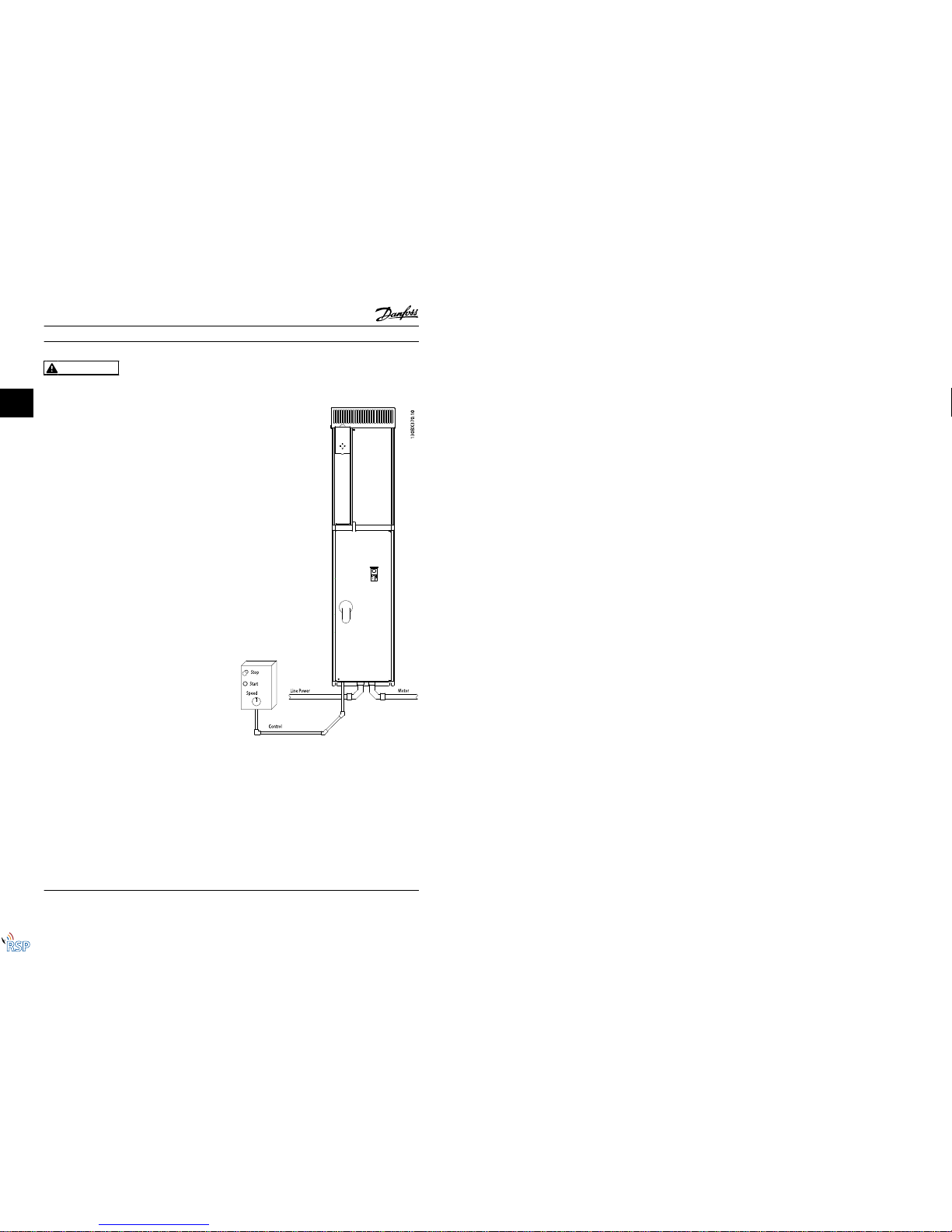
1Introduction
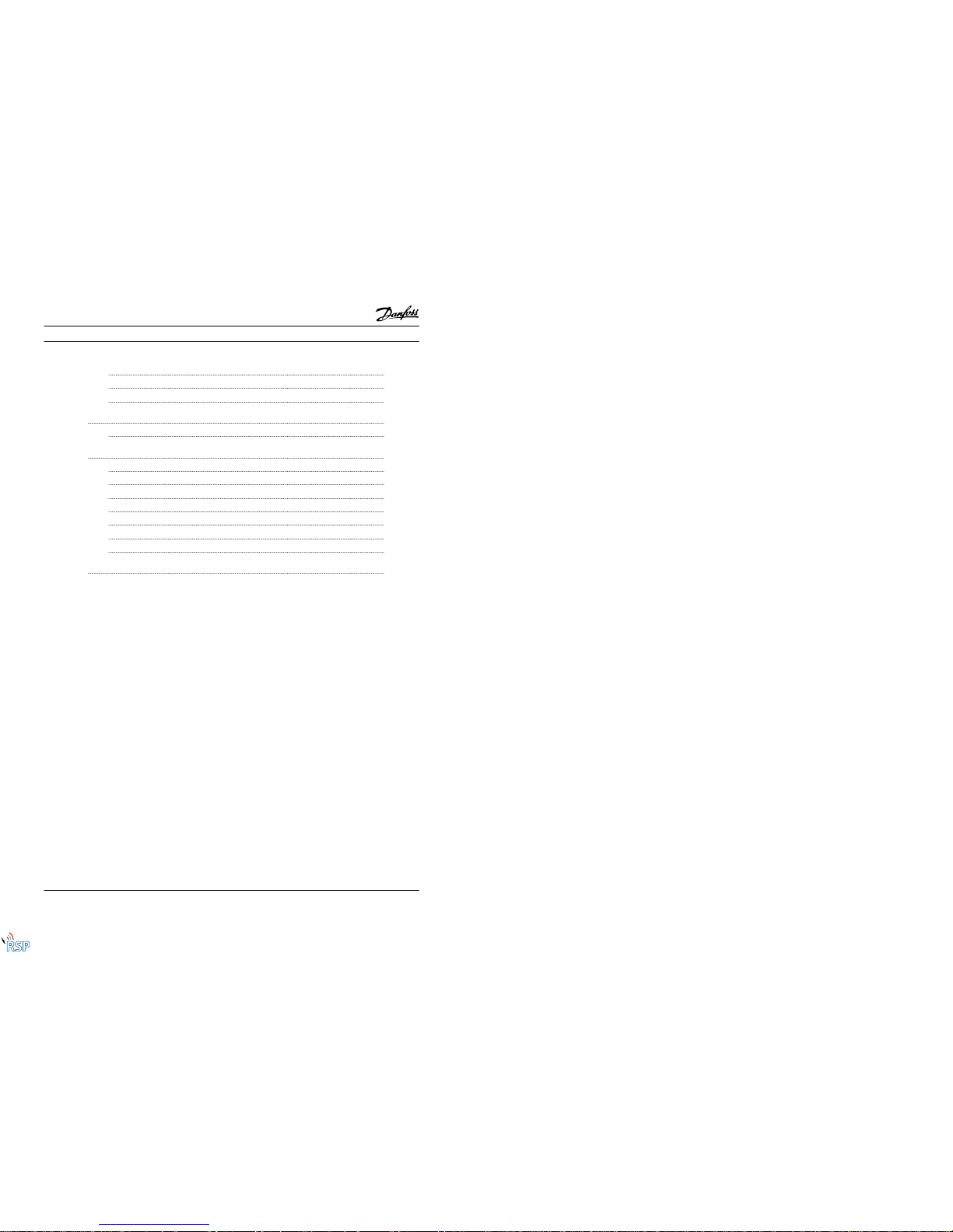
1.1 Exploded Views
Figure 1.1 D1 Interior Components
Figure 1.2 Close-up View: LCP and Control Functions
Introduction VLT® Automation VT Drive FC 322 D-Frame Instruction Manual
MG21E122 - VLT® is a registered Danfoss trademark 1-1
1 1
Remote Site Products - 1-888-532-2706 - www.remotesiteproducts.com
http://www.remotesiteproducts.com/p-20776-Danfoss-131X8139-VLT-Automation-VT-Drive-VFD-FC322-230V-20-HP.aspx
Page 9
1 LCP (Local Con trol Panel) 9 Relay 2 (04, 05, 06)
2 RS-485 serial bus connector 10 Lifting ring
3 Digital I/O and 24 V power supply 11 Mounting slot
4 Analog I/O con nector 12 Cable clamp (PE)
5 USB connector 13 Earth (ground)
6 Serial bus terminal switch 14 Motor output terminals 96 (U), 97 (V), 98 (W)
7 Analog switches (A53), (A54) 15 Mains input terminals 91 (L1), 92 (L2), 93 (L3)
8 Relay 1 (01, 02, 03)
Table 1.1
1.2 Purpose of the Manual
This manual is intended to provide detailed information for
the installation and start up of the frequency converter.
2 Installation provides requirements for mechanical and
electrical installation, including input, motor, control and
serial communications wiring, and control terminal
functions. 3 Start Up and Commissioning provides detailed
procedures for start up, basic operational programming,
and functional testing. The remaining chapters provide
supplementary details. These details include user interface,
detailed programming, application examples, start-up
troubleshooting, and specifications.
1.3 Additional Resources
Other resources are available to understand advanced
frequency converter functions and programming.
•
The VLT® Programming Guide provides greater
detail on working with parameters and many
application examples.
•
The VLT® Design Guide is intended to provide
detailed capabilities and functionality to design
motor control systems.
•
Optional equipment is available that may change
some of the procedures described. Reference the
instructions supplied with those options for
specific requirements. Contact the local Danfoss
supplier or visit the Danfoss website for
downloads or additional information.
1.4 Product Overview
A frequency converter is an electronic motor controller
that converts AC mains input into a variable AC waveform
output. The frequency and voltage of the output are
regulated to control the motor speed or torque. The
frequency converter can vary the speed of the motor in
response to system feedback, such as position sensors on a
conveyor belt. The frequency converter can also regulate
the motor by responding to remote commands from
external controllers.
In addition, the frequency converter monitors the system
and motor status, issues warnings or alarms for fault
conditions, starts and stops the motor, optimizes energy
efficiency, and offers many more control, monitoring, and
efficiency functions. Operation and monitoring functions
are available as status indications to an outside control
system or serial communication network.
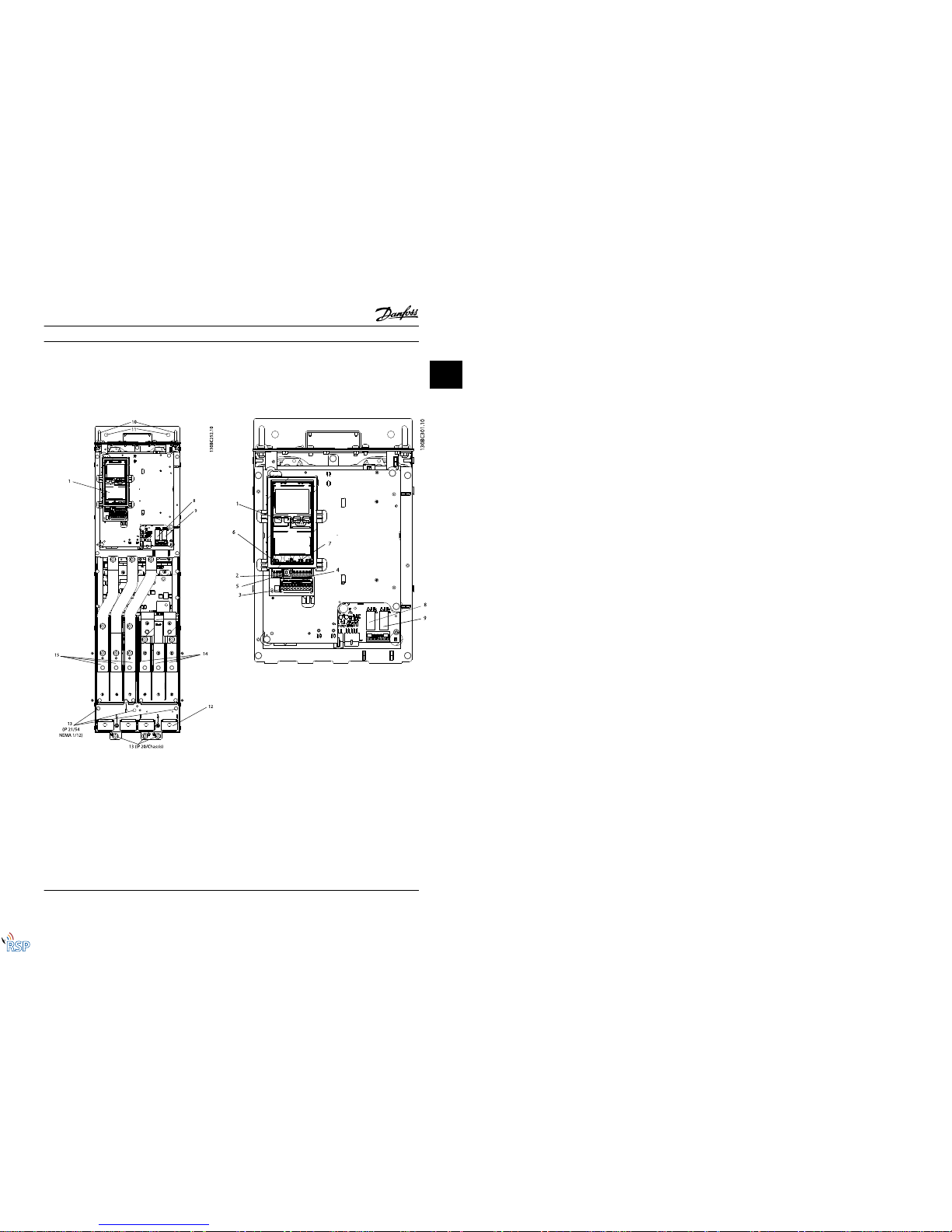
1.5 Internal Controller Functions
Figure 1.3 is a block diagram of the frequency converter's
internal components. See Table 1.2 for their functions.
Figure 1.3 Frequency Converter Block Diagram
Area Title Functions
1Mains input•Three-phase AC mains power
supply to the frequency
converter
2Rectifier
•
The rectifier bridge converts
the AC input to DC current to
supply inverter power
3DC bus
•
Intermediate DC-bus circuit
handles the DC current
Introduction VLT® Automation VT Drive FC 322 D-Frame Instruction Manual
1-2 MG21E122 - VLT® is a registered Danfoss trademark
1
Remote Site Products - 1-888-532-2706 - www.remotesiteproducts.com
http://www.remotesiteproducts.com/p-20776-Danfoss-131X8139-VLT-Automation-VT-Drive-VFD-FC322-230V-20-HP.aspx
Page 10
Area Title Functions
4 DC reactors
•
Filter the intermediate DC
circuit voltage
•
Prove line transient protection
•
Reduce RMS current
•
Raise the power factor
reflected back to the line
•
Reduce harmonics on the AC
input
5 Capacitor bank
•
Stores the DC power
•
Provides ride-through
protection for short power
losses
6Inverter
•
Converts the DC into a
controlled PWM AC waveform
for a controlled variable
output to the motor
Area Title Functions
7 Output to motor•Regulated three-phase output
power to the motor
8 Control circuitry
•
Input power, internal
processing, output, and motor
current are monitored to
provide efficient operation
and control
•
User interface and external
commands are monitored and
performed
•
Status output and control can
be provided
Table 1.2 Frequency Converter Internal Components
1.6 Frame Sizes and Power Ratings
kW rated frequency converters
kW High Overload 75 90 110 132 160 200 250 315 315
kW Normal Overloa d 90 110 132 160 200 250 315 355 400
400 V D3h D3h D3h D4h D4h D4h
500 V D3h D3h D3h D4h D4h D4h
525 V D4h D3h D3h D4h D4h D4h D4h
690 V D3h D3h D3h D4h D4h D4h
Table 1.3
Horsepower rated frequency converters
HP High
Overload
100 125 150 200 250 300 350 350
HP Normal
Overload
125 150 200 250 300 350 400 450
460 V D3h D3h D3h D4h D4h D4h
575 V D3h D3h D3h D4h D4h D4h D4h
Table 1.4
Introduction VLT® Automation VT Drive FC 322 D-Frame Instruction Manual
MG21E122 - VLT® is a registered Danfoss trademark 1-3
1 1
Remote Site Products - 1-888-532-2706 - www.remotesiteproducts.com
http://www.remotesiteproducts.com/p-20776-Danfoss-131X8139-VLT-Automation-VT-Drive-VFD-FC322-230V-20-HP.aspx
Page 11
Introduction VLT® Automation VT Drive FC 322 D-Frame Instruction Manual
1-4 MG21E122 - VLT® is a registered Danfoss trademark
1
Remote Site Products - 1-888-532-2706 - www.remotesiteproducts.com
http://www.remotesiteproducts.com/p-20776-Danfoss-131X8139-VLT-Automation-VT-Drive-VFD-FC322-230V-20-HP.aspx
Page 12
2 Installation
2.1 Planning the Installation Site
CAUTION
Before performing the installation it is important to plan
the installation of the frequency converter. Neglecting this
may result in extra work during and after installation.
Select the best possible operation site by considering the
following (see details on the following pages, and the
respective Design Guides):
•
Ambient operating temperature
•
Installation method
•
How to cool the unit
•
Position of the frequency converter
•
Cable routing
•
Ensure the power source supplies the correct
voltage and necessary current
•
Ensure that the motor current rating is within the
maximum current from the frequency converter
•
If the frequency converter is without built-in
fuses, ensure that the external fuses are rated
correctly.
Installation in High Altitudes
Voltage Altitude Restrictions
380-500 V At altitudes above 3 km, contact Danfoss regardin g
PELV
525-690 V At altitudes above 2 km, contact Danfoss regardin g
PELV.
Table 2.1
2.2 Pre-Installation Check List
•
Before unpacking the frequency converter, ensure
the packaging is intact. If any damage has
occurred, immediately contact the shipping
company to claim the damage.
•
Before unpacking the frequency converter, locate
it as close as possible to the final installation site.
•
Compare the model number on the nameplate to
what was ordered to verify the proper
equipment.
•
Ensure each of the following are rated for the
same voltage:
•
Mains (power)
•
Frequency converter
•
Motor
•
Ensure that frequency converter output current
rating is equal to or greater than motor full load
current for peak motor performance.
•
Motor size and frequency converter
power must match for proper overload
protection.
•
If frequency converte r rating is less than
motor, full motor output cannot be
achieved.
2.3 Mechanical Installation
2.3.1 Cooling
•
Top and bottom clearance for air cooling must be
provided. Generally, 225 mm (9 in) is required.
•
Improper mounting can result in over heating
and reduced performance
•
Derating for temperatures starting between 45° C
(113° F) and 50° C (122° F) and elevation 1000 m
(3300 ft) above sea level must be considered. See
VLT
®
Design Guide for detailed information.
The high power Danfoss VLT frequency converters utilize a
back-channel cooling concept that removes heatsink
cooling air, which carries approximately 90% of the heat
out of the back channel of the frequency converters. The
back-channel air can be redirected from the panel or room
using one of the kits below.
Duct cooling
A back-channel cooling kit is available to direct the
heatsink cooling air out of the panel when an IP20/chassis
frequency converters is installed in a Rittal enclosure. Use
of this kit reduces the heat in the panel and smaller door
fans can be specified on the enclosure.
Cooling out the back (top and bottom covers)
The back channel cooling air can be ventilated out of the
room so that the heat from the back channel is not
dissipated into the control room.
Installation VLT® Automation VT Drive FC 322 D-Frame Instruction Manual
MG21E122 - VLT® is a registered Danfoss trademark 2-1
2
2
Remote Site Products - 1-888-532-2706 - www.remotesiteproducts.com
http://www.remotesiteproducts.com/p-20776-Danfoss-131X8139-VLT-Automation-VT-Drive-VFD-FC322-230V-20-HP.aspx
Page 13
A door fan(s) is required on the enclosure to remove the
heat not contained in the backchannel of the frequency
converters and any additional losses generated by other
components inside the enclosure. The total re quired air
flow must be calculated so that the appropriate fans can
be selected.
Airflow
The necessary airflow over the heat sink must be secured.
The flow rate is shown in Table 2.2.
The fan runs for the following reasons:
•
AMA
•
DC Hold
•
Pre-Mag
•
DC Brake
•
60% of nominal current is exceeded
•
Specific heatsink temperature exceeded (power
size dependent).
•
Specific Power Card ambient temperature
exceeded (power size dependent)
•
Specific Control Card ambient temperature
exceeded
Frame Door fan/top fan Heatsink fan
D1h/D3h
102 m
3
/hr (60 C FM) 420 m3/hr (250 CFM)
D2h/D4h
204 m
3
/hr (120 CFM) 8 40 m3/hr (500 CFM)
Table 2.2 Airflow
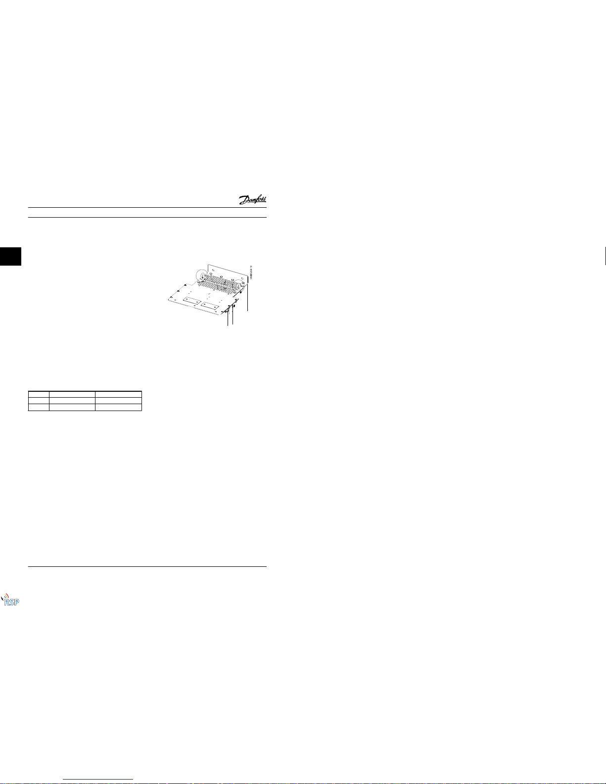
2.3.2 Lifting
Always lift the frequency converter using the dedicated
lifting eyes. Use a bar to avoid bending the lifting holes.
Figure 2.1 Position Lifting Straps where Indicated
CAUTION
The angle from the top of the frequency converter to the
lifting cables should be 60 ° or greater.
2.3.3 Wall Mounting - IP21 (NEMA 1) and
IP54 (NEMA 12) Units
Consider the following before selecting the final installation site:
•
Free space for cooling
•
Access to open the door
•
Cable entry from the bottom
Installation VLT® Automation VT Drive FC 322 D-Frame Instruction Manual
2-2 MG21E122 - VLT® is a registered Danfoss trademark
2
Remote Site Products - 1-888-532-2706 - www.remotesiteproducts.com
http://www.remotesiteproducts.com/p-20776-Danfoss-131X8139-VLT-Automation-VT-Drive-VFD-FC322-230V-20-HP.aspx
Page 14
2.4 Electrical Installation
2.4.1 General Requirements
This section contains detailed instructions for wiring the
frequency converter. The following tasks are describ ed:
•
Wiring the motor to the frequency converter
output terminals
•
Wiring the AC mains to the frequency converter
input terminals
•
Connecting control and serial communication
wiring
•
After power has been applied, checking input
and motor power; programming control terminals
for their intended functions
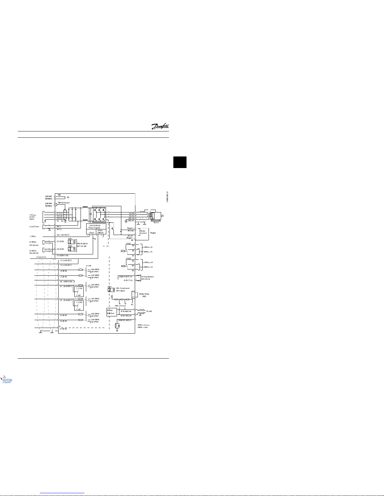
Figure 2.2
Installation VLT® Automation VT Drive FC 322 D-Frame Instruction Manual
MG21E122 - VLT® is a registered Danfoss trademark 2-3
2
2
Remote Site Products - 1-888-532-2706 - www.remotesiteproducts.com
http://www.remotesiteproducts.com/p-20776-Danfoss-131X8139-VLT-Automation-VT-Drive-VFD-FC322-230V-20-HP.aspx
Page 15
WARNING
EQUIPMENT HAZARD!
Rotating shafts and electrical equipment can be haz ardous.
All electrical work must conform to national and local
electrical codes. It is strongly recommended that installation, start up, and maintenance be performed only by
trained and qualified personnel. Failure to follow these
guidelines could result in death or serious injury.
CAUTION
WIRING ISOLATION!
Run input power, motor wiring and control wiring in three
separate metallic conduits or use separated shielded cable
for high frequency noise isolation. Failure to isolate power,
motor and control wiring could result in less than
optimum frequency converter and associated equipment
performance.
For your safety, comply with the following requirements
•
Electronic controls equipment is connected to
hazardous mains voltage. Extreme care should be
taken to protect against electrical hazards when
applying power to the unit.
•
Run motor cables from multiple frequency
converters separately. Induced voltage from
output motor cables run together can charge
equipment capacitors even with the equipment
turned off and locked out.
•
Field wiring terminals are not intended to receive
a conductor one size larger.
Overload and Equipment Protection
•
An electronically activ ated function within the
frequency converter provides overload protection
for the motor. The overload calculates the level of
increase to activate timing for the trip (controller
output stop) function. The higher the current
draw, the quicker the trip response. The overload
provides Class 20 motor protection. See
8 Warnings and Alarms for details on the trip
function.
•
Because the motor wiring carries high frequency
current, it is important that wiring for mains,
motor power, and control are run separately. Use
metallic conduit or separated shielded wire. See
Figure 2.3. Failure to isolate power, motor, and
control wiring could result in less than optimum
equipment performance.
•
All frequency converters must be provided with
short-circuit and over-current protection. Input
fusing is required to provide this protection, see
Figure 2.4. If not factory supplied, fuses must be
provided by the installer as part of installation.
See maximum fuse ratings in 10.3.1 Protection.
Figure 2.3 Example of Proper Electrical Installation Using Conduit
Installation VLT® Automation VT Drive FC 322 D-Frame Instruction Manual
2-4 MG21E122 - VLT® is a registered Danfoss trademark
2
Remote Site Products - 1-888-532-2706 - www.remotesiteproducts.com
http://www.remotesiteproducts.com/p-20776-Danfoss-131X8139-VLT-Automation-VT-Drive-VFD-FC322-230V-20-HP.aspx
Page 16
•
All frequency converters must be provided with
short-circuit and over-current protection. Input
fusing is required to provide this protection, see
Figure 2.4. If not factory supplied, fuses must be
provided by the installer as part of installation.
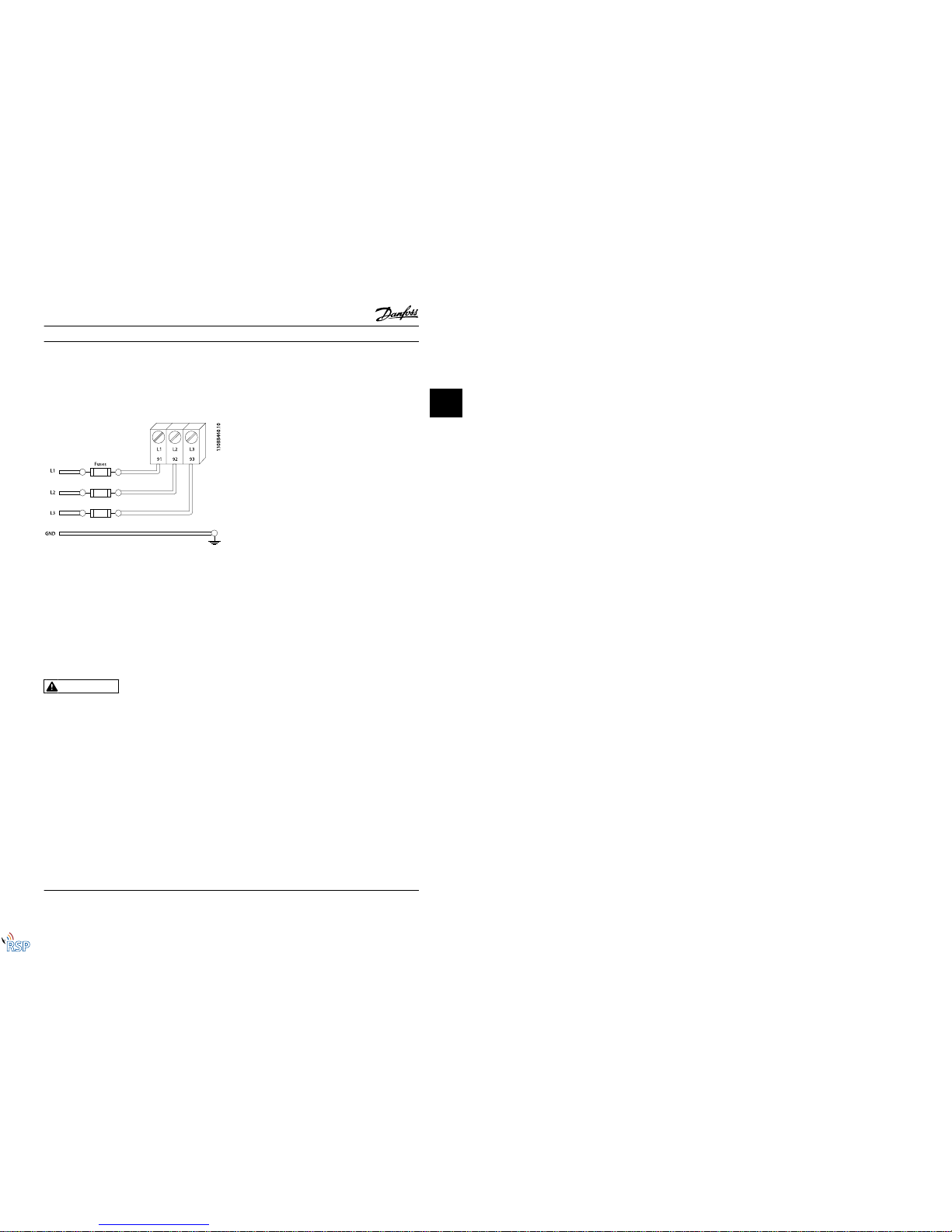
See maximum fuse ratings in 10.3.1 Protection.
Figure 2.4 Frequency Converter Fuses
Wire Type and Ratings
•
All wiring must comply with local and national
regulations regarding cross-section and ambient
temperature requirements.
•
Danfoss recommends that all power connections
be made with a minimum 75° C rated copper
wire.
2.4.2 Earth (Grounding) Requirements
WARNING
EARTHING (GROUNDING) HAZARD!
For operator safety, it is important to earth (ground) the
frequency converter properly in accordance with national
and local electrical codes as well as instructions contained
within this document. Do not use conduit connected to
the frequency converter as a replacement for p roper
grounding. Earth (ground) currents are higher than 3.5 mA.
Failure to earth (ground) the frequency converter pro perly
could result in death or serious injury.Earthing (grounding)
hazard
NOTE!
It is the responsibility of the user or certified electrical
installer to ensure correct earthing (grounding) of the
equipment in accordance with national and local electrical
codes and standards.
•
Follow all local and national electrical code s to
earth (ground) electrical equipment properly.
•
Proper protective earthing (grounding) for
equipment with earth (ground) currents higher
than 3.5 mA must be established, see
2.4.2.1 Leakage Current (>3.5 mA).
•
A dedicated earth wire (ground wire) is r equired
for input power, motor power and control wiring.
•
Use the clamps provided with the equipment for
proper earth connections (ground connections).
•
Do not earth (ground) one frequency converter to
another in a “daisy chain” fashion.
•
Keep the earth (ground) wire connections as
short as possible.
•
Using high-strand wire to reduce electrical noise
is recommended.
•
Follow motor manufacturer wiring requirements.
2.4.2.1 Leakage Current (>3.5 mA)
Follow national and local codes regarding pro tective
earthing of equipment with a leakage current > 3.5 mA.
Frequency converter technology implies high frequency
switching at high power. This will generate a leakage
current in the earth connection. A fault curren t in the
frequency converter at the output power terminals might
contain a DC component, which can charge the filter
capacitors and cause a transient earth current. The earth
leakage current depends on various system configurations
including RFI filtering, screened motor cables, and
frequency converter power.
EN/IEC61800-5-1 (Power Drive System Product Standard)
requires special care if the leakage current exceeds 3.5 mA.
Earthing (grounding) must be reinforced in one of the
following ways:
•
Earth (ground) wire of at least 10 mm
2
•
Two separate earth (ground) wires both
complying with the dimensioning rules.
See EN 60364-5-54 § 543.7 for further information.
Using RCDs
Where residual current devices (RCDs)–also known as earth
leakage circuit breakers (ELCBs)–are used, comply with the
following: residual current de vices (RCDs)
•
Use RCDs of type B only, which are capable of
detecting AC and DC currents.
•
Use RCDs with an inrush delay to prevent faults
due to transient earth currents.
•
Dimension RCDs according to the system configuration and environmental considerations.
Installation VLT® Automation VT Drive FC 322 D-Frame Instruction Manual
MG21E122 - VLT® is a registered Danfoss trademark 2-5
2
2
Remote Site Products - 1-888-532-2706 - www.remotesiteproducts.com
http://www.remotesiteproducts.com/p-20776-Danfoss-131X8139-VLT-Automation-VT-Drive-VFD-FC322-230V-20-HP.aspx
Page 17
2.4.2.2 Earthing (Grounding) IP20
Enclosures
The frequency converter can be earthed (grounded) using
conduit or shielded cable. For earthing (grounding) of the
power connections, use the dedicated earthing
(grounding) points as shown in Figure 2.6.
Figure 2.5 Earthing (Grounding) Points for IP20 (Chassis)
Enclosures
2.4.2.3 Earthing (Grounding) IP21/54
Enclosures
The frequency converter can be earthed (grounded) using
conduit or shielded cable. For earthing (grounding) of the
power connections, use the dedicated earthing
(grounding) points as shown in Figure 2.6.
Figure 2.6 Earth ing (Grounding) for IP21/54 Enclosures.
Installation VLT® Automation VT Drive FC 322 D-Frame Instruction Manual
2-6 MG21E122 - VLT® is a registered Danfoss trademark
2
Remote Site Products - 1-888-532-2706 - www.remotesiteproducts.com
http://www.remotesiteproducts.com/p-20776-Danfoss-131X8139-VLT-Automation-VT-Drive-VFD-FC322-230V-20-HP.aspx
Page 18
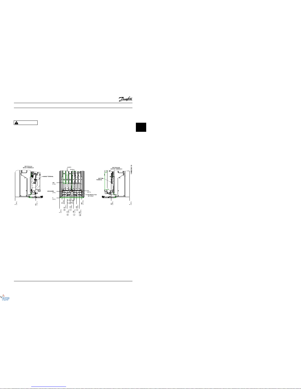
2.4.3 Motor Connection
WARNING
INDUCED VOLTAGE!
Run output motor cables from multiple frequency
converters separately. Induced voltage from output motor
cables run together can charge equipment capacitors even
with the equipment turned off and locked out. Failure to
run output motor cables separately could result in death
or serious injury.
•
For maximum cable sizes, see 10.1 Power-
dependent Specifications..
•
Comply with local and national electrical codes
for cable sizes.
•
Gland plates are provided at the base of IP21/54
and higher (NEMA1/12) units.
•
Do not install power factor correction capacitors
between the frequency converter and the motor.
•
Do not wire a starting or pole-changing device
between the frequency converter and the motor.
•
Connect the 3-phase motor wiring to terminals
96 (U), 97 (V), and 98 (W).
•
Earth (ground) the cable in accordance with the
instructions provided.
•
Torque terminals in accordance with the
information provided in 10.3.4 Connection
Tightening Torques
•
Follow motor manufacturer wiring requirements.
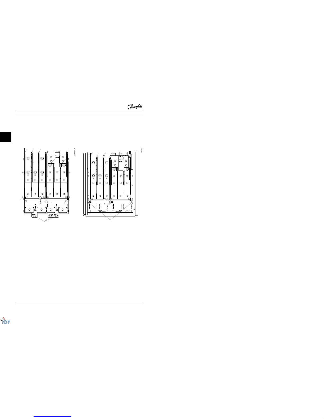
Figure 2.7 Termi nal Locations D1h
Installation VLT® Automation VT Drive FC 322 D-Frame Instruction Manual
MG21E122 - VLT® is a registered Danfoss trademark 2-7
2
2
Remote Site Products - 1-888-532-2706 - www.remotesiteproducts.com
http://www.remotesiteproducts.com/p-20776-Danfoss-131X8139-VLT-Automation-VT-Drive-VFD-FC322-230V-20-HP.aspx
Page 19
Figure 2.8 Termi nal Locations D3h
Figure 2.9 Termi nal Locations D2h
Installation VLT® Automation VT Drive FC 322 D-Frame Instruction Manual
2-8 MG21E122 - VLT® is a registered Danfoss trademark
2
Remote Site Products - 1-888-532-2706 - www.remotesiteproducts.com
http://www.remotesiteproducts.com/p-20776-Danfoss-131X8139-VLT-Automation-VT-Drive-VFD-FC322-230V-20-HP.aspx
Page 20
Figure 2.10 Termina l Locations D4h
Installation VLT® Automation VT Drive FC 322 D-Frame Instruction Manual
MG21E122 - VLT® is a registered Danfoss trademark 2-9
2
2
Remote Site Products - 1-888-532-2706 - www.remotesiteproducts.com
http://www.remotesiteproducts.com/p-20776-Danfoss-131X8139-VLT-Automation-VT-Drive-VFD-FC322-230V-20-HP.aspx
Page 21
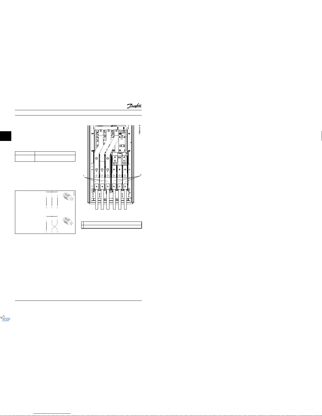
2.4.4 Motor Cable
The motor must be connected to terminals U/T1/96, V/
T2/97, W/T3/98. Earth (ground) to terminal 99. All types of
three-phase asynchronous standard motors can be used
with a frequency converter unit. The factory settin g is for
clockwise rotation with the frequency converter output
connected as follows:
Terminal No. Function
96, 97, 98, 99 Mains U/T1, V/T2, W/T3
Earth (ground)
Table 2.3
2.4.5 Motor Rotation Check
The direction of rotation can be changed b y switching two
phases in the motor cable or by changing the setting of
4-10 Motor Speed Direction.
•
Terminal U/T1/96 connected
to U-phase
•
Terminal V/T2/97 connected
to V-phase
•
Terminal W/T3/98
connected to W-phase
Table 2.4
A motor rotation check can be performed using1-28 Motor
Rotation Check and following the steps shown i n the
display.
2.4.6 AC Mains Connection
•
Size wiring is based upon the input current of the
frequency converter.
•
Comply with local and national electrical codes
for cable sizes.
•
Connect 3-phase AC input power wiring to
terminals L1, L2, and L3 (see Figure 2.11).
Figure 2.11 Connecting to AC Mains
1 Mains connection
2 Motor connection
Table 2.5
•
Earth (ground) the cable in accordance with the
instructions provided.
•
All frequency converters may be used with an
isolated input source as well as with earth
(ground) reference power lines. When supplied
from an isolated mains source (IT mains or
floating delta) or TT/TN-S mains with a grounded
leg (grounded delta), set 14-50 RFI Filter to OFF.
When off, the internal RFI filter capacitors
between the chassis and the intermediate circui t
are isolated to avoid damage to the intermediate
circuit and to reduce earth (ground) capacity
currents in accordance with IEC 61800-3.
Installation VLT® Automation VT Drive FC 322 D-Frame Instruction Manual
2-10 MG21E122 - VLT® is a registered Danfoss trademark
2
Remote Site Products - 1-888-532-2706 - www.remotesiteproducts.com
http://www.remotesiteproducts.com/p-20776-Danfoss-131X8139-VLT-Automation-VT-Drive-VFD-FC322-230V-20-HP.aspx
Page 22
2.5 Control Wiring Connection
•
Isolate control wiring from high power
components in the frequency converter.
•
If the frequency converter is connected to a
thermistor, for PELV isolation, optional thermistor
control wiring must be reinforced/double
insulated. A 24 V DC supply voltage is
recommended.
2.5.1 Access
All terminals to the control cables are loc ated underneath
the LCP on the inside of the frequency converter. To
access, open the door (IP21/54) or remove the front panel
(IP20).
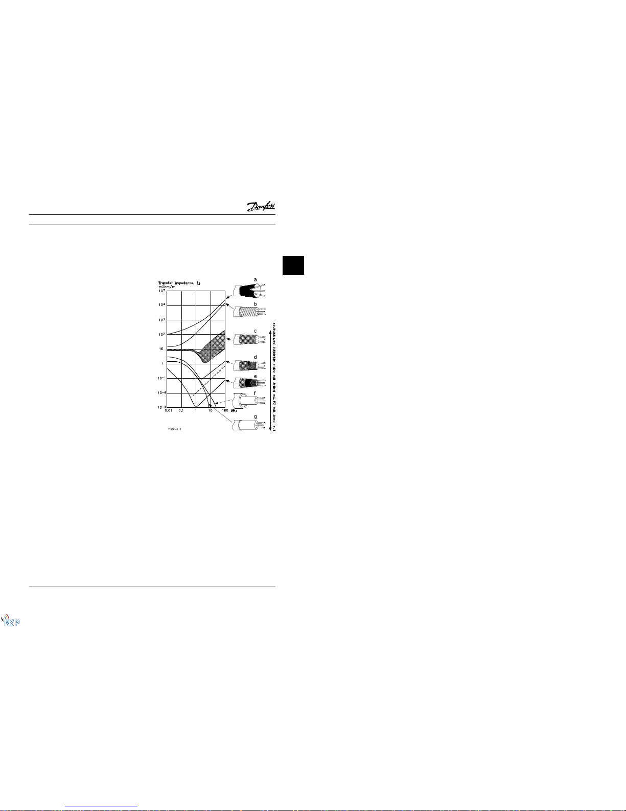
2.5.2 Using Screened Control Cables
Danfoss recommends braided screened/armoured cables to
optimise EMC immunity of the control cables and the EMC
emission from the motor cables.
The ability of a cable to reduce the incoming and
outgoing radiation of electric noise depends on the
transfer impedance (Z
T
). The screen of a cable is normally
designed to reduce the transfer of electric noise; however,
a screen with a lower transfer impedance (Z
T
) value is
more effective than a screen with a higher transfer
impedance (Z
T
).
Transfer impedance (Z
T
) is rarely stated by cable manufacturers but it is often possible to estimate transfer
impedance (Z
T
) by assessing the physical design of the
cable.
Transfer impedance (Z
T
) can be assessed on the basis of
the following factors:
- The conductibility of the screen material.
- The contact resistance between the individual
screen conductors.
- The screen coverage, i.e. the physical area of the
cable covered by the screen - often stated as a
percentage value.
- Screen type, i.e. braided or twisted pattern.
a. Aluminium-clad with copper wire.
b. Twisted copper wire or armoured steel wire cable.
c. Single-layer braided co pper wire with varying
percentage screen coverage.
This is the typical Danfoss reference cable.
d. Double-layer braided copper wire.
e. Twin layer of braided copper wire with a
magnetic, screened/armoured intermediate layer.
f. Cable that runs in copper tube or steel tube.
g. Lead cable with 1.1 mm wall thickness.
Figure 2.12
Installation VLT® Automation VT Drive FC 322 D-Frame Instruction Manual
MG21E122 - VLT® is a registered Danfoss trademark 2-11
2
2
Remote Site Products - 1-888-532-2706 - www.remotesiteproducts.com
http://www.remotesiteproducts.com/p-20776-Danfoss-131X8139-VLT-Automation-VT-Drive-VFD-FC322-230V-20-HP.aspx
Page 23
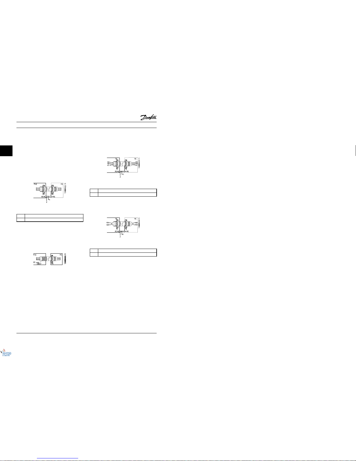
2.5.3 Earthing (Grounding) of Screened
Control Cables
Correct screening
The preferred method in most cases is to secure control
and serial communication cables with screening clamps
provided at both ends to ensure best possible high
frequency cable contact. If the earth (ground) potential
between the frequency converter and the PLC is different,
electric noise may occur that will disturb the entire system.
Solve this problem by fitting an equalizing cable next to
the control cable. Minimum cable cross section: 16 mm
2
.
Figure 2.13
1
Min. 16 mm
2
2Equalizing cable
Table 2.6
50/60 Hz earth (ground) loops
With very long control cables, earth loops (ground loops)
may occur. To eliminate earth (ground) loops, connect one
end of the screen-to-earth (ground) with a 100 nF
capacitor (keeping leads short).
Figure 2.14
Avoid EMC noise on serial communication
This terminal is connected to earth (ground) via an internal
RC link. Use twisted-pair cables to reduce interference
between conductors. The recommended method is shown
below:
Figure 2.15
1
Min. 16 mm
2
2 Equalizing cable
Table 2.7
Alternatively, the connection to terminal 61 can be
omitted:
Figure 2.16
1
Min. 16 mm
2
2 Equalizing cable
Table 2.8
Installation VLT® Automation VT Drive FC 322 D-Frame Instruction Manual
2-12 MG21E122 - VLT® is a registered Danfoss trademark
2
Remote Site Products - 1-888-532-2706 - www.remotesiteproducts.com
http://www.remotesiteproducts.com/p-20776-Danfoss-131X8139-VLT-Automation-VT-Drive-VFD-FC322-230V-20-HP.aspx
Page 24
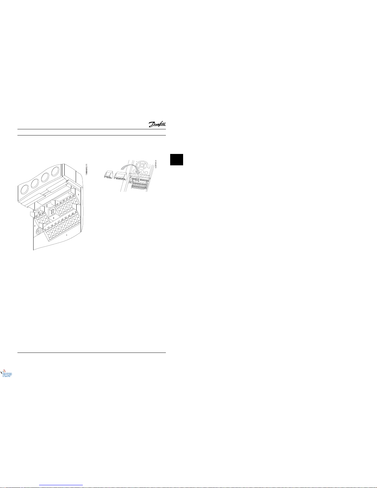
2.5.4 Control Terminal Types
Terminal functions and default settings are summarized in
2.5.6 Control Terminal Functions.
Figure 2.17 Control Terminal Locations
•
Connector 1 provides four programmable digital
input terminals, two additional digital terminals
programmable as either input or output, a 24 V
DC terminal supply voltage, and a common for
optional customer supplied 24 V DC voltage.
•
Connector 2 terminals (+)68 and (-)69 are for an
RS-485 serial communications connection.
•
Connector 3 provides two analog inputs, one
analog output, 10 V DC supply voltage, and
commons for the inputs and output.
•
Connector 4 is a USB port available for use with
the MCT 10 Set-up Software.
•
Also provided are two Form C relay outputs that
are in various locations depending upon the
frequency converter configuration and size.
•
Some options available for ordering with the unit
may provide additional terminals. See the manual
provided with the equipment option.
2.5.5 Wiring to Control Terminals
Terminal plugs can be removed for easy access.
Figure 2.18
2.5.6 Control Terminal Functions
Frequency converter functions are commanded by
receiving control input signals.
•
Each terminal must be programmed for the
function it will be supporting in the parameters
associated with that terminal. See 5 Programming
and 6 Application Examplesfor terminals and
associated parameters.
•
It is important to confirm that the control
terminal is programmed for the correct function.
See 5 Programming for details on accessing
parameters and programming.
•
The default terminal programming is intended to
initiate frequency converter functioning in a
typical operational mode.
2.6 Serial Communication
RS-485 is a two-wire bus interface compatible with multidrop network topology, i.e. nodes can be connected as a
bus, or via drop cables from a common trunk line. A total
of 32 nodes can be connected to one network segment.
Repeaters divide network segments. Each repeater
functions as a node within the segment i n which it is
installed. Each nod e connected within a giv en network
must have a unique node address across all segments.
Terminate each segment at both ends, using either the
termination switch (S801) of the frequency converter or a
biased termination resistor network. Always use screened
twisted pair (STP) cable for bus cabling, and always follow
good common installation practice.
Low-impedance earth (ground) connection of the screen at
every node is important, including at high frequencies.
Thus, connect a large surface of the sc reen to earth
Installation VLT® Automation VT Drive FC 322 D-Frame Instruction Manual
MG21E122 - VLT® is a registered Danfoss trademark 2-13
2
2
Remote Site Products - 1-888-532-2706 - www.remotesiteproducts.com
http://www.remotesiteproducts.com/p-20776-Danfoss-131X8139-VLT-Automation-VT-Drive-VFD-FC322-230V-20-HP.aspx
Page 25
(ground), for example with a cable clamp or a conductive
cable gland. It may be necessary to apply potentialequalizing cables to maintain the same earth (ground)
potential throughout the network. Particularly in installations with long cables.
To prevent impedance mismatch, always use the same
type of cable throughout the entire network. When
connecting a motor to the frequency converter, always use
screened motor cable.
Cable Screened twisted pair (STP)
Impedance
120
Ω
Max. cable length 1200 m (including drop lines)
500 m station-to-station
Table 2.9
Installation VLT® Automation VT Drive FC 322 D-Frame Instruction Manual
2-14 MG21E122 - VLT® is a registered Danfoss trademark
2
Remote Site Products - 1-888-532-2706 - www.remotesiteproducts.com
http://www.remotesiteproducts.com/p-20776-Danfoss-131X8139-VLT-Automation-VT-Drive-VFD-FC322-230V-20-HP.aspx
Page 26

3 Start Up and Commissioning
3.1 Pre-start
CAUTION
Before applying power to the unit, inspect the entire
installation as detailed in Table 3.1. Check mark those items
when completed.
Inspect for Description
☑
Auxiliary equipment•Look for auxiliary equipment, switches, disconnects, or input fuses/circuit breakers that may
reside on the input power side of the frequency converter o r output side to the motor. Ensure
that they are ready for full speed operation .
•
Check function and installation of any sensors used for feedback to the frequency converter.
•
Remove power factor correction caps on motor(s), if present.
Cable routing
•
Ensure that input power, motor wiring , and control wiring are separated or in three separate
metallic conduits for high frequency noise isolation.
Control wiring
•
Check for broken or damaged wires and loose connections.
•
Check that control wiring is isolated from power and motor wiring for noise immunity.
•
Check the voltage source of the signals, if necessary.
•
The use of shielded cable or twisted pair is recommended. Ensure that the shield is terminated
correctly.
Cooling clearance
•
Measure that top and bottom clearance is adequate to ensure proper air flow for cooling.
EMC considerations
•
Check for prop er installation regarding elec tromagnetic compatibility.
Environmental consider-
ations
•
See equipment label for the maximum ambient operating temperature limits.
•
Humidity levels must be 5-95% non-condensing.
Fusing and circuit
breakers
•
Check for prop er fusing or circuit breakers.
•
Check that all fuses are inserted firmly and in operational condition and that all circuit breakers
are in the open position.
Earthing (Grounding)
•
The unit requires an earth wire(ground wire) from its chassis to the building earth (ground).
•
Check for good earth connections(ground connections) that a re tight and free of oxidation.
•
Earthing (grounding) to conduit or mounting the back panel to a metal surface is not a
suitable earth (ground).
Input and output power
wiring
•
Check for loose connections.
•
Check that motor and mains are in separate conduit or separated screened cables.
Panel interior
•
Inspect that the unit interior is free of dirt, metal chips, moisture, and corrosion.
Switches
•
Ensure that all switch and disconnect settings are in the proper positions.
Vibration
•
Check that the unit is mounted solidly or that shock mounts are used, as necessary.
•
Check for an unusual amount of vibration.
Table 3.1 Start Up Check List
Start Up and Commissioning VLT® Automation VT Drive FC 322 D-Frame Instruction Manual
MG21E122 - VLT® is a registered Danfoss trademark 3-1
3
3
Remote Site Products - 1-888-532-2706 - www.remotesiteproducts.com
http://www.remotesiteproducts.com/p-20776-Danfoss-131X8139-VLT-Automation-VT-Drive-VFD-FC322-230V-20-HP.aspx
Page 27

3.2 Applying Power to the Frequency Converter
WARNING
HIGH VOLTAGE!
Frequency converters contain high voltage when
connected to AC mains. Installation, start-up and
maintenance should be performed by qualified personnel
only. Failure to perform installation, start-up and
maintenance by qualified personnel could result i n death
or serious injury.
WARNING
UNINTENDED START!
When the frequency converter is connected to AC mains,
the motor may start at any time. The frequency converter,
motor, and any driven equipment must be in operational
readiness. Failure to be in operational readiness when the
frequency converter is connected to AC mains could result
in death, serious injury, equipment, or property damage.
1. Confirm input voltage is balanced within 3%. If
not, correct input voltage imbalance before
proceeding. Repeat procedure after voltage
correction.
2. Ensure optional equipment wiring, if present,
matches installation application.
3. Ensure that all operator devices are in the OFF
position. Panel doors closed or cover mounted.
4. Apply power to the unit. DO NOT start the
frequency converter at this time. For units with a
disconnect switch, turn to the ON position to
apply power to the frequency converter.
NOTE!
If the status line at the bottom of the LCP reads AUTO
REMOTE COAST, this indicates that the unit is ready to
operate but is missing an input signal on terminal 27.
3.3 Basic Operational Programming
Frequency converters require basic operational
programming before running for best performance. Basic
operational programming requires entering motornameplate data for the motor being operated and the
minimum and maximum motor speeds. Parameter settings
recommended are intended for start up and checkout
purposes. Application settings may vary. See 4.1 Local
Control Panel for detailed instructions on entering data
through the LCP.
Enter data with power ON, but bef ore operating the
frequency converter. There are two ways of programming
the frequency converter: either by using the Smart
Application Set-up (SAS) or by using the procedure
described further down. The SAS is a quick wizard for
setting up the most commonly used applications. At first
power-up and after a reset the SAS appears on the LCP.
Follow the instructions that appear on the successive
screens for setting-up the applications listed. SAS can also
be found under the Quick Menu. [Info] can be used
throughout the Smart Set-up to see help information for
various selections, settings, and messages.
NOTE!
The start conditions will be ignored while in the wizard.
NOTE!
If no action is taken after first power-up or reset, the SAS
screen will automatically disappear after 10 minutes.
When not using the SAS, enter data in accordance with
the following procedure.
1. Press [Main Menu] twice on the LCP.
2. Use the navigation keys to scroll to parameter
group 0-** Operation/Display and press [OK].
Figure 3.1
Start Up and Commissioning VLT® Automation VT Drive FC 322 D-Frame Instruction Manual
3-2 MG21E122 - VLT® is a registered Danfoss trademark
3
Remote Site Products - 1-888-532-2706 - www.remotesiteproducts.com
http://www.remotesiteproducts.com/p-20776-Danfoss-131X8139-VLT-Automation-VT-Drive-VFD-FC322-230V-20-HP.aspx
Page 28

3. Use navigation keys to scroll to parameter group
0-0* Basic Settings and press [OK].
Figure 3.2
4. Use navigation keys to scroll to 0-03 Regional
Settings and press [OK].
Figure 3.3
5. Use navigation keys to select International or
North America as appropriate and press [OK]. (This
changes the default settings for a number of
basic parameters. See 5.5 Parameter Menu
Structure for a complete list.)
6. Press [Quick Menu] on the LCP.
7. Use the navigation keys to scroll to parameter
group Q2 Quick Setup and press [OK].
Figure 3.4
8. Select language and press [OK]. Then enter the
motor data i n 1-20 Motor Power [kW] /1-21 Motor
Power [HP] through 1-25 Motor Nominal Speed.
The information can be found on the motor
nameplate.
1-20 Motor Power [kW] or 1-21 Motor
Power [HP]
1-22 Motor Voltage
1-23 Motor Frequency
1-24 Motor Current
1-25 Motor Nominal Speed
Figure 3.5
9. A jumper wire should be in place between
control terminals 12 and 27. If this is the case,
leave 5-12 Terminal 27 Digital Input at factory
default. Otherwise select No Operation. For
frequency converters with an optional Danfoss
bypass, no jumper wire is required.
10. 3-02 Minimum Reference
11. 3-03 Maximum Reference
12. 3-41 Ramp 1 Ramp Up Time
13. 3-42 Ramp 1 Ramp Down Time
14. 3-13 Reference Site. Linked to Hand/Auto* Local
Remote.
This concludes the quick set-up procedure. Press [Status]
to return to the operational display.
Start Up and Commissioning VLT® Automation VT Drive FC 322 D-Frame Instruction Manual
MG21E122 - VLT® is a registered Danfoss trademark 3-3
3
3
Remote Site Products - 1-888-532-2706 - www.remotesiteproducts.com
http://www.remotesiteproducts.com/p-20776-Danfoss-131X8139-VLT-Automation-VT-Drive-VFD-FC322-230V-20-HP.aspx
Page 29

3.4 Local-control Test
CAUTION
MOTOR START!
Ensure that the motor, system and any attached
equipment are ready for start. It is the responsibility of the
user to ensure safe operation under any condition. Failure
to ensure that the motor, system, and any attached
equipment is ready for start could result in personal injury
or equipment damage.
NOTE!
The [Hand On] key provides a local start command to the
frequency converter. The [Off] key provides the stop
function.
When operating in local mode, [
▲
] and [▼] increase and
decrease the speed output of the frequency converter. [◄]
and [►] move the display cursor in the numeric display.
1. Press [Hand On].
2. Accelerate the frequency converter by pressing
[
▲
] to full speed. Moving the cursor left of the
decimal point provides quicker input changes.
3. Note any acceleration problems.
4. Press [Off].
5. Note any deceleration problems.
If acceleration problems were encountered
•
If warnings or alarms occur, see 8 Warnings and
Alarms.
•
Check that motor data is entered correctly.
•
Increase the ramp-up time in 3-41 Ramp 1 Ramp
Up Time.
•
Increase current limit in 4-18 Current Limit.
•
Increase torque limit in 4-16 Torque Limit Motor
Mode.
If deceleration problems were encountered
•
If warnings or alarms occur, see .
•
Check that motor data is entered correctly.
•
Increase the ramp-down time in 3-42 Ramp 1
Ramp Down Time.
•
Enable overvoltage control in 2-17 Over-voltage
Control.
NOTE!
The OVC algorithm does not work when using PM motors.
See 4.1.1 Local Control Panel for resetting the frequency
converter after a trip.
NOTE!
3.2 Applying Power to the Frequency Converter through
3.3 Basic Operational Programming in this chapter
concludes the p rocedures for applying power to the
frequency converter, basic programming, set-up, and
functional testing.
3.5 System Start Up
The procedure in this section requires user-wiring and
application programming to be completed. See
6 Application Examples for application set-up information.
The following procedure is recommended after application
set-up by the user is completed.
CAUTION
MOTOR START!
Ensure that the motor, system, and any attached
equipment is ready for start. It is the responsibility of the
user to ensure safe operation under any co ndition. Failure
to do so could result in personal injury or equipment
damage.
1. Press [Auto On].
2. Ensure that external control functions are
properly wired to the frequency converter and all
programming is completed.
3. Apply an external run command.
4. Adjust the speed reference throughout the speed
range.
5. Remove the external run command.
6. Note any problems.
If warnings or alarms occur, see 8 Warnings and Alarms.
Start Up and Commissioning VLT® Automation VT Drive FC 322 D-Frame Instruction Manual
3-4 MG21E122 - VLT® is a registered Danfoss trademark
3
Remote Site Products - 1-888-532-2706 - www.remotesiteproducts.com
http://www.remotesiteproducts.com/p-20776-Danfoss-131X8139-VLT-Automation-VT-Drive-VFD-FC322-230V-20-HP.aspx
Page 30

4 User Interface
4.1 Local Control Panel
The local control panel (LCP) is the combined display and
keypad on the front of the unit. The LCP is the user
interface to the frequency converter.
The LCP has several user functions.
•
Start, stop, and control speed when in local
control.
•
Display operational data, status, warnings and
cautions.
•
Programming frequency converter functions.
•
Manually reset the frequency converter after a
fault when auto-reset is inactive.
An optional numeric LCP (NLCP) is also avail able. The NLCP
operates in a manner similar to the LCP. See VLT
®
Programming Guide, for details on use of the NLCP.
4.1.1 LCP Layout
The LCP is divided into four functional groups (see
Figure 4.1).
Figure 4.1 LCP
a. Display area.
b. Display menu keys for changing the display to
show status options, programming, or error
message history.
c. Navigation keys for programming functions,
moving the display cursor, and speed control in
local operation. Also included are the status
indicator lights.
d. Operational mode keys and reset.
User Interface VLT® Automation VT Drive FC 322 D-Frame Instruction Manual
MG21E122 - VLT® is a registered Danfoss trademark 4-1
4
4
Remote Site Products - 1-888-532-2706 - www.remotesiteproducts.com
http://www.remotesiteproducts.com/p-20776-Danfoss-131X8139-VLT-Automation-VT-Drive-VFD-FC322-230V-20-HP.aspx
Page 31

4.1.2 Setting LCP Display Values
The display area is activated when the frequency converter
receives power from mains voltage, a DC bus terminal, or
an external 24 V supply.
The information displayed on the LCP can be customized
for user application.
•
Each display readout has a parameter associated
with it.
•
Options are selected in the quick menu Q3-13
Display Settings.
•
Display 2 has an alternate larger display option.
•
The frequency converter status at the bottom line
of the display is generated automatically and is
not selectable.
Display Parameter number Default setting
1.1 0-20 Motor RPM s
1.2 0-21 Motor current
1.3 0-22 Motor power (kW)
2 0-23 Motor frequency
3 0-24 Reference in percent
Table 4.1
Figure 4.2
Figure 4.3
4.1.3 Display
Menu keys are used for menu access for parameter set-up,
toggling through status display modes during normal
operation, and viewing fault log data.
Figure 4.4
Key Function
Status Shows operationa l information.
•
In Auto mode, press to toggle between
status read-out displays
•
Press repeatedly to scroll through each
status display
•
Press [Status] plus [▲] or [▼] to adjust the
display brightness
•
The symbol in the upper right corner of the
display shows the direction of motor
rotation and which set-up is active. This is
not programmable.
Quick Menu Allows access to programming parameters for
initial set up instructions and many detailed
application instructions.
•
Press to access Q2 Quick Setup for
sequenced instructions to program the basic
frequency controller set up
•
Follow the sequence of parameters as
presented for the function set up
Main Menu Allows access to all programming parameters.
•
Press twice to access top-level index
•
Press once to return to the last location
accessed
•
Press to enter a parameter number for
direct access to that parameter
Alarm Log Displays a list of current warnings, the last 10
alarms, and the maintenance log.
•
For details about the frequency converter
before it entered the alarm mode, select the
alarm number using the navigation keys
and press [OK].
Table 4.2
User Interface VLT® Automation VT Drive FC 322 D-Frame Instruction Manual
4-2 MG21E122 - VLT® is a registered Danfoss trademark
4
Remote Site Products - 1-888-532-2706 - www.remotesiteproducts.com
http://www.remotesiteproducts.com/p-20776-Danfoss-131X8139-VLT-Automation-VT-Drive-VFD-FC322-230V-20-HP.aspx
Page 32

4.1.4 Navigation Keys
Navigation keys are used for programming functions and
moving the display cursor. The navigation keys also
provide speed control in local (hand) operation. Three
frequency converter status indicator lights are also located
in this area.
Figure 4.5
Key Function
Back Reverts to the previous step or list in the menu
structure.
Cancel Cancels the last cha nge or command as long as
the display mode has not changed.
Info Press for a definition of the functi on being
displayed.
Navigation
Keys
Use the four navigation keys to move between
items in the menu.
OK Use to access parameter groups or to ena ble a
choice.
Table 4.3
Light Indicator Fun ction
Green ON The ON light activates when the
frequency converter receives
power from mains voltage, a DC
bus terminal, or an external 24 V
supply.
Yellow WARN When warning conditions are met,
the yellow WARN light comes on
and text appears in the display
area identifying the problem.
Red ALARM A fault condition causes the red
alarm light to flash and an alarm
text is displayed.
Table 4.4
4.1.5 Operation Keys
Operation keys are found at the bottom of the LCP.
Figure 4.6
Key Function
Hand On Starts the frequency converter in local control.
•
Use the navigation keys to control frequency
converter speed
•
An external stop signal by control input or
serial communication overrides the local hand
on
Off Stops the motor but does not remove power to
the frequency converter.
Auto On Pu ts the system in remo te operational mode.
•
Responds to an external start command by
control terminals or serial communication
•
Speed reference is from an external source
Reset Resets the frequency converter manually after a
fault has been cleared.
Table 4.5
4.2 Back Up and Copying Parameter
Settings
Programming data is stored internally in the frequency
converter.
•
The data can be uploaded into the LCP memory
as a storage back up
•
Once stored in the LCP, the data can be
downloaded back into the frequency converter
•
Data can also be downloaded into other
frequency converters by connecting the LCP into
those units and downloading the stored settings.
(This is a quick way to program multiple units
with the same settings.)
•
Initialisation of the frequency converter to restore
factory default settings does not change data
stored in the LCP memory
User Interface VLT® Automation VT Drive FC 322 D-Frame Instruction Manual
MG21E122 - VLT® is a registered Danfoss trademark 4-3
4
4
Remote Site Products - 1-888-532-2706 - www.remotesiteproducts.com
http://www.remotesiteproducts.com/p-20776-Danfoss-131X8139-VLT-Automation-VT-Drive-VFD-FC322-230V-20-HP.aspx
Page 33

WARNING
UNINTENDED START!
When the frequency converter is connected to AC mains,
the motor may start at any time. The frequency converter,
motor, and any driven equipment must be in operational
readiness. Failure to be in operational readiness when the
frequency converter is connected to AC mains could result
in death, serious injury, or equipment or property damage.
4.2.1 Uploading Data to the LCP
1. Press [Off] to stop the motor before uploading or
downloading data.
2. Go to 0-50 LCP Copy.
3. Press [OK].
4.
Select All to LCP.
5. Press [OK]. A progress bar shows the uploading
process.
6. Press [Hand On] or [Auto On] to return to normal
operation.
4.2.2 Downloading Data from the LCP
1. Press [Off] to stop the motor before uploading or
downloading data.
2. Go to 0-50 LCP Copy.
3. Press [OK].
4. Select All from LCP.
5. Press [OK]. A progress bar shows the
downloading process.
6. Press [Hand On] or [Auto On] to return to normal
operation.
4.3 Restoring Default Settings
CAUTION
Initialisation restores t he unit to factory default settings.
Any programming, motor data, localization, and
monitoring records will be lost. Uploading data to the LCP
provides a backup before initialisation.
Restoring the frequency converter parameter settings back
to default values is done by initialisation of the frequency
converter. Initialisation can be through 14-22 Operation
Mode or manually.
•
Initialisation using 14-22 Operation Mode does not
change frequency converter data such as
operating hours, serial communication selections,
personal menu settings, fault log, alarm log, and
other monitoring functions
•
Using 14-22 Operation Mode is generally
recommended
•
Manual initialisation erases all motor,
programming, localization, and monitoring data
and restores factory default settings
4.3.1 Recommended Initialisation
1. Press [Main Menu] twice to access parameters.
2.
Scroll to 14-22 Operation Mode.
3. Press [OK].
4. Scroll to Initialisation .
5. Press [OK].
6. Remove power to the unit and wait for the
display to turn off.
7. Apply power to the unit.
Default parameter settings are restored during start up.
This may take slightly longer than normal.
8. Alarm 80 is displayed.
9. Press [Reset] to return to operation mode.
4.3.2 Manual Initialisation
1. Remove power to the unit and wait for the
display to turn off.
2. Press and hold [Status], [Main Menu], and [OK] at
the same time and apply power to the unit.
Factory default parameter settings are restored during start
up. This may take slightly longer than normal.
Manual initialisation does not the following frequency
converter information
•
15-00 Operating Hours
•
15-03 Power Up's
•
15-04 Over Temp's
•
15-05 Over Volt's
User Interface VLT® Automation VT Drive FC 322 D-Frame Instruction Manual
4-4 MG21E122 - VLT® is a registered Danfoss trademark
4
Remote Site Products - 1-888-532-2706 - www.remotesiteproducts.com
http://www.remotesiteproducts.com/p-20776-Danfoss-131X8139-VLT-Automation-VT-Drive-VFD-FC322-230V-20-HP.aspx
Page 34

5Programming
5.1 Introduction
The frequency converter is programmed for its application
functions using parameters. Parameters are accessed by
pressing either [Quick Menu] or [Main Menu] on the LCP.
(See 4.1 Local Control Panel for details on using the LCP
function keys.) Parameters may also be accessed through a
PC using the MCT 10 Set-up Software (see 5.6.1 Remote
Programming with MCT 10 Set-up Software).
The quick menu is intended for initial start up (Q2-** Quick
Set Up) and detailed instructions for common frequency
converter applications (Q3-** Function Set Up). Step-by-step
instructions are provided. These instructions enable the
user to walk through the parameters used for
programming applications i n their proper sequence. Data
entered in a parameter can change the options available in
the parameters following that entry. The quick menu
presents easy guidelines for getting most systems up and
running.
The main menu accesses all parameters and allows for
advanced frequency converter applications.
5.2 Programming Example
Here is an example for programming the frequency
converter for a common application in open loop using
the quick menu.
•
This procedure programs the frequency converter
to receive a 0-10 V DC analog control signal on
input terminal 53.
•
The frequency converter will respond by
providing 20-50 Hz output to the motor proportional to the input signal (0-10 V DC = 20-50 Hz).
This is a common pump or fan ap plication.
Press [Quick Menu] and select the following parameters
using the navigation keys to scroll to the titles and press
[OK] after each action.
1. Q3 Function Setups
2. Parameter Data Set
Figure 5.1
3. Q3-2 Open Loop Settings
Figure 5.2
4. Q3-21 Analog Reference
Figure 5.3
Programming VLT® Automation VT Drive FC 322 D-Frame Instruction Manual
MG21E122 - VLT® is a registered Danfoss trademark 5-1
5
5
Remote Site Products - 1-888-532-2706 - www.remotesiteproducts.com
http://www.remotesiteproducts.com/p-20776-Danfoss-131X8139-VLT-Automation-VT-Drive-VFD-FC322-230V-20-HP.aspx
Page 35

5. 3-02 Minimum Reference. Set minimum internal
frequency converter reference to 0 Hz. (This sets
the minimum frequency converter speed at 0 Hz .)
Figure 5.4
6. 3-03 Maximum Reference. Set maximum internal
frequency converter reference to 60 Hz. (This sets
the maximum frequency converter speed at 60
Hz. Note that 50/60 Hz is a regional variation.)
Figure 5.5
7. 6-10 Terminal 53 Low Voltage. Set minimum
external voltage reference on Terminal 53 at 0 V.
(This sets the minimum input signal at 0 V.)
Figure 5.6
8. 6-11 Terminal 53 High Voltage. Set maximum
external voltage reference on Terminal 53 at 10 V.
(This sets the maximum input signal at 10 V.)
Figure 5.7
9. 6-14 Terminal 53 Low Ref./Feedb. Value. Set
minimum speed reference on Terminal 53 at 20
Hz. (This tells the frequency converter that the
minimum voltage received on Terminal 53 (0 V)
equals 20 Hz output.)
Figure 5.8
10. 6-15 Terminal 53 High Ref./Feedb. Value. Set
maximum speed reference on Terminal 53 at 50
Hz. (This tells the frequency converter that the
maximum voltage received on Terminal 53 (10 V)
equals 50 Hz output.)
Figure 5.9
With an external device providing a 0-10 V control signal
connected to frequency converter terminal 53, the system
is now ready for operation. Note that the scroll bar on th e
right in the last illustration of the display is at the bottom,
indicating the procedure is complete.
Figure 5.10 shows the wiring connections used to enable
this set up.
Programming VLT® Automation VT Drive FC 322 D-Frame Instruction Manual
5-2 MG21E122 - VLT® is a registered Danfoss trademark
5
Remote Site Products - 1-888-532-2706 - www.remotesiteproducts.com
http://www.remotesiteproducts.com/p-20776-Danfoss-131X8139-VLT-Automation-VT-Drive-VFD-FC322-230V-20-HP.aspx
Page 36

Figure 5.10 Wiring Example for External Device Providing 0-10 V
Control Signal
5.3 Control Terminal Programming
Examples
Control terminals can be programmed.
•
Each terminal has specified functions it is capable
of performing
•
Parameters associated with the terminal enable
the function
•
For proper frequency converter functioning, the
control terminals must be
Wired properly
Programmed for the intended function
Receiving a signal
See Table 5.1 for control terminal parameter number and
default setting. (Default setting can change based on the
selection in 0-03 Regiona l Settings.)
The following example shows accessing Terminal 18 to see
the default setting.
1. Press [Main Menu] twice, scroll to parameter
group 5-** Digital In/Out Parameter Data Set and
press [OK].
Figure 5.11
2. Scroll to parameter group 5-1* Digital Inputs an d
press [OK].
Figure 5.12
3. Scroll to 5-10 Terminal 18 Digital Input. Press [OK]
to access function choices. The default setting
Start is shown.
Figure 5.13
5.4 International/North American Default
Parameter Settings
Setting 0-03 Regional Settings [0] International or [1] North
America changes the default settings for some parameters.
Table 5.1 lists those parameters that are affected.
Parameter International
Default Parameter
Value
North American
Default Parameter
Value
0-03 Regional
Settings
International North America
0-71 Date Format DD-MM-YYYY MM/DD/YYYY
0-72 Time Format 24 h 12 h
1-20 Motor Power
[kW]
See Note 1 See Note 1
1-21 Motor Power
[HP]
See Note 2 See Note 2
1-22 Motor Voltage 230 V/400 V/575 V 208 V/460 V/575 V
1-23 Motor
Frequency
50 Hz 60 Hz
3-03 Maximum
Reference
50 Hz 60 Hz
3-04 Reference
Function
Sum External/Preset
Programming VLT® Automation VT Drive FC 322 D-Frame Instruction Manual
MG21E122 - VLT® is a registered Danfoss trademark 5-3
5
5
Remote Site Products - 1-888-532-2706 - www.remotesiteproducts.com
http://www.remotesiteproducts.com/p-20776-Danfoss-131X8139-VLT-Automation-VT-Drive-VFD-FC322-230V-20-HP.aspx
Page 37

Parameter International
Default Parameter
Value
North American
Default Parameter
Value
4-13 Motor Speed
High Limit [RPM]
See Note 3
1500 RPM 1800 RPM
4-14 Motor Speed
High Limit [Hz]
See Note 4
50 Hz 60 Hz
4-19 Max Output
Frequency
100 Hz 120 Hz
4-53 Warning Speed
High
1500 RPM 1800 RPM
5-12 Terminal 27
Digital Input
Coast inverse External interlock
5-40 Function Relay Alarm No alarm
6-15 Terminal 53
High Ref./Feedb.
Value
50 60
6-50 Terminal 42
Output
Speed 0 - HighLim Speed 4-20 mA
14-20 Reset Mode Manual reset Infinite auto reset
22-85 Speed at
Design Point [RPM]
See Note 3
1500 RPM 1800 RPM
22-86 Speed at
Design Point [Hz]
50 Hz 60 Hz
24-04 Fire Mode
Max Reference
50 Hz 60 Hz
Table 5.1 International/North American Default Parameter Settings
5.5 Parameter Menu Structure
Establishing the correct programming for applications
often requires setting functions in several related
parameters. These parameter settings provide the
frequency converter with system details it needs to
operate properly. System details may include such things
as input and output signal types, programming terminals,
minimum and maximum signal ranges, custom displays,
automatic restart, and other features.
•
See the LCP display to view detailed parameter
programming and settin g options
•
Press [Info] in any menu location to view
additional details for that function
•
Press and hold [Main Menu] to enter a parameter
number for direct access to that parameter
•
Details for common application set ups are
provided in 6 Application Examples
Programming VLT® Automation VT Drive FC 322 D-Frame Instruction Manual
5-4 MG21E122 - VLT® is a registered Danfoss trademark
5
Remote Site Products - 1-888-532-2706 - www.remotesiteproducts.com
http://www.remotesiteproducts.com/p-20776-Danfoss-131X8139-VLT-Automation-VT-Drive-VFD-FC322-230V-20-HP.aspx
Page 38

5.5.1 Main Menu
Structure
0-** Operation / Display
0-0* Basic Settings
0-01 Language
0-02 Motor Speed Unit
0-03 Regional Settings
0-04 Operating State at Power-up
0-05 Local Mode Unit
0-1* Set-up Operations
0-10 Active Set-up
0-11 Programming Set-up
0-12 This Set-up Linked to
0-13 Readout: Linked Set-ups
0-14 Readout: Prog. Set-ups / Channel
0-2* LCP Display
0-20 Display Line 1.1 Small
0-21 Display Line 1.2 Small
0-22 Display Line 1.3 Small
0-23 Display Line 2 Large
0-24 Display Line 3 Large
0-25 My Personal Menu
0-3* LCP Custom Readout
0-30 Custom Readout Unit
0-31 Custom Readout Min Value
0-32 Custom Readout Max Value
0-37 Display Text 1
0-38 Display Text 2
0-39 Display Text 3
0-4* LCP Keypad
0-40 [Hand on] Key on LCP
0-41 [Off] Key on LCP
0-42 [Auto on] Key on LCP
0-43 [Reset] Key on LCP
0-44 [Off/Reset] Key on LCP
0-45 [Drive Bypass] Key on LCP
0-5* Copy/Save
0-50 LCP Copy
0-51 Set-up Copy
0-6* Password
0-60 Main Menu Password
0-61 Access to Main Menu w/o Password
0-65 Personal Menu Password
0-66 Access to Personal Menu w/o
Password
0-7* Clock Settings
0-70 Date and Time
0-71 Date Format
0-72 Time Format
0-74 DST/Summertime
0-76 DST/Summertime Start
0-77 DST/Summertime End
0-79 Clock Fault
0-81 Working Days
0-82 Additional Working Days
0-83 Additional Non-Working Days
0-89 Date and Time Readout
1-** Load and Motor
1-0* General Settings
1-00 Configuration Mode
1-03 Torque Characteristics
1-06 Clockwise Direction
1-1* Motor Selection
1-10 Motor Construction
1-1* VVC+ PM
1-14 Damping Gain
1-15 Low Speed Filter Time Const.
1-16 High Speed Filter Time Const.
1-17 Voltage filter time const.
1-2* Motor Data
1-20 Motor Power [kW]
1-21 Motor Power [HP]
1-22 Motor Voltage
1-23 Motor Frequency
1-24 Motor Current
1-25 Motor Nominal Speed
1-26 Motor Cont. Rated Torque
1-28 Motor Rotation Check
1-29 Automatic Motor Adaptation (AMA)
1-3* Adv. Motor Data
1-30 Stator Resistance (Rs)
1-31 Rotor Resistance (Rr)
1-35 Main Reactance (Xh)
1-36 Iron Loss Resistance (Rfe)
1-37 d-axis Inductance (Ld)
1-39 Motor Poles
1-40 Back EMF at 1000 RPM
1-5* Load Indep. Setting
1-50 Motor Magnetisation at Zero Speed
1-51 Min Speed Normal Magnetising
[RPM]
1-52 Min Speed Normal Magnetising [Hz]
1-58 Flystart Test Pulses Current
1-59 Flystart Test Pulses Frequency
1-6* Load Depen. Setting
1-60 Low Speed Load Compensation
1-61 High Speed Load Compensation
1-62 Slip Compensation
1-63 Slip Compensation Time Constant
1-64 Resonance Dampening
1-65 Resonance Dampening Time
Constant
1-66 Min. Current at Low Speed
1-7* Start Adjustments
1-70 PM Startmode
1-71 Start Delay
1-72 Start Function
1-73 Flying Start
1-77 Compressor Start Max Speed [RPM]
1-78 Compressor Start Max Speed [Hz]
1-79 Compressor Start Max Time to Trip
1-8* Stop Adjustments
1-80 Function at Stop
1-81 Min Speed for Function at Stop
[RPM]
1-82 Min Speed for Function at Stop [Hz]
1-86 Trip Speed Low [RPM]
1-87 Trip Speed Low [Hz]
1-9* Motor Temperature
1-90 Motor Thermal Protection
1-91 Motor External Fan
1-93 Thermistor Source
2-** Brakes
2-0* DC-Brake
2-00 DC Hold/Preheat Current
2-01 DC Brake Current
2-02 DC Braking Time
2-03 DC Brake Cut In Speed [RPM]
2-04 DC Brake Cut In Speed [Hz]
2-06 Parking Current
2-07 Parking Time
2-1* Brake Energy Funct.
2-10 Brake Function
2-11 Brake Resistor (ohm)
2-12 Brake Power Limit (kW)
2-13 Brake Power Monitoring
2-15 Brake Check
2-16 AC brake Max. Current
2-17 Over-voltage Control
3-** Reference / Ramps
3-0* Reference Limits
3-02 Minimum Reference
3-03 Maximum Reference
3-04 Reference Function
3-1* References
3-10 Preset Reference
3-11 Jog Speed [Hz]
3-13 Reference Site
3-14 Preset Relative Reference
3-15 Reference 1 Source
3-16 Reference 2 Source
3-17 Reference 3 Source
3-19 Jog Speed [RPM]
3-4* Ramp 1
3-41 Ramp 1 Ramp Up Time
3-42 Ramp 1 Ramp Down Time
3-5* Ramp 2
3-51 Ramp 2 Ramp Up Time
3-52 Ramp 2 Ramp Down Time
3-8* Other Ramps
3-80 Jog Ramp Time
3-81 Quick Stop Ramp Time
3-82 Starting Ramp Up Time
3-9* Digital Pot.Meter
3-90 Step Size
3-91 Ramp Time
3-92 Power Restore
3-93 Maximum Limit
3-94 Minimum Limit
3-95 Ramp Delay
4-** Limits / Warnings
4-1* Motor Limits
4-10 Motor Speed Direction
4-11 Motor Speed Low Limit [RPM]
4-12 Motor Speed Low Limit [Hz]
4-13 Motor Speed High Limit [RPM]
4-14 Motor Speed High Limit [Hz]
4-16 Torque Limit Motor Mode
4-17 Torque Limit Generator Mode
4-18 Current Limit
4-19 Max Output Frequency
4-5* Adj. Warnings
4-50 Warning Current Low
4-51 Warning Current High
4-52 Warning Speed Low
4-53 Warning Speed High
4-54 Warning Reference Low
4-55 Warning Reference High
4-56 Warning Feedback Low
4-57 Warning Feedback High
4-58 Missing Motor Phase Function
4-6* Speed Bypass
4-60 Bypass Speed From [RPM]
4-61 Bypass Speed From [Hz]
4-62 Bypass Speed To [RPM]
4-63 Bypass Speed To [Hz]
4-64 Semi-Auto Bypass Set-up
5-** Digital In/Out
5-0* Digital I/O mode
5-00 Digital I/O Mode
5-01 Terminal 27 Mode
5-02 Terminal 29 Mode
5-1* Digital Inputs
5-10 Terminal 18 Digital Input
5-11 Terminal 19 Digital Input
5-12 Terminal 27 Digital Input
5-13 Terminal 29 Digital Input
5-14 Terminal 32 Digital Input
5-15 Terminal 33 Digital Input
5-16 Terminal X30/2 Digital Input
5-17 Terminal X30/3 Digital Input
5-18 Terminal X30/4 Digital Input
5-19 Terminal 37 Safe Stop
5-3* Digital Outputs
5-30 Terminal 27 Digital Output
5-31 Terminal 29 Digital Output
5-32 Term X30/6 Digi Out (MCB 101)
5-33 Term X30/7 Digi Out (MCB 101)
5-4* Relays
5-40 Function Relay
5-41 On Delay, Relay
5-42 Off Delay, Relay
5-5* Pulse Input
5-50 Term. 29 Low Frequency
5-51 Term. 29 High Frequency
5-52 Term. 29 Low Ref./Feedb. Value
5-53 Term. 29 High Ref./Feedb. Value
5-54 Pulse Filter Time Constant #29
5-55 Term. 33 Low Frequency
5-56 Term. 33 High Frequency
5-57 Term. 33 Low Ref./Feedb. Value
5-58 Term. 33 High Ref./Feedb. Value
5-59 Pulse Filter Time Constant #33
5-6* Pulse Output
5-60 Terminal 27 Pulse Output Variable
5-62 Pulse Output Max Freq #27
5-63 Terminal 29 Pulse Output Variable
5-65 Pulse Output Max Freq #29
5-66 Terminal X30/6 Pulse Output Variable
5-68 Pulse Output Max Freq #X30/6
5-8* I/O Options
5-80 AHF Cap Reconnect Delay
5-9* Bus Controlled
5-90 Digital & Relay Bus Control
5-93 Pulse Out #27 Bus Control
5-94 Pulse Out #27 Timeout Preset
5-95 Pulse Out #29 Bus Control
5-96 Pulse Out #29 Timeout Preset
5-97 Pulse Out #X30/6 Bus Control
5-98 Pulse Out #X30/6 Timeout Preset
6-** Analog In/Out
6-0* Analog I/O Mode
6-00 Live Zero Timeout Time
6-01 Live Zero Timeout Function
6-02 Fire Mode Live Zero Timeout
Function
6-1* Analog Input 53
6-10 Terminal 53 Low Voltage
6-11 Terminal 53 High Voltage
6-12 Terminal 53 Low Current
6-13 Terminal 53 High Current
6-14 Terminal 53 Low Ref./Feedb. Value
6-15 Terminal 53 High Ref./Feedb. Value
6-16 Terminal 53 Filter Time Constant
6-17 Terminal 53 Live Zero
6-2* Analog Input 54
6-20 Terminal 54 Low Voltage
6-21 Terminal 54 High Voltage
6-22 Terminal 54 Low Current
6-23 Terminal 54 High Current
6-24 Terminal 54 Low Ref./Feedb. Value
6-25 Terminal 54 High Ref./Feedb. Value
6-26 Terminal 54 Filter Time Constant
6-27 Terminal 54 Live Zero
6-3* Analog Input X30/11
6-30 Terminal X30/11 Low Voltage
6-31 Terminal X30/11 High Voltage
6-34 Term. X30/11 Low Ref./Feedb. Value
6-35 Term. X30/11 High Ref./Feedb. Value
6-36 Term. X30/11 Filter Time Constant
6-37 Term. X30/11 Live Zero
6-4* Analog Input X30/12
6-40 Terminal X30/12 Low Voltage
6-41 Terminal X30/12 High Voltage
6-44 Term. X30/12 Low Ref./Feedb. Value
6-45 Term. X30/12 High Ref./Feedb. Value
6-46 Term. X30/12 Filter Time Constant
6-47 Term. X30/12 Live Zero
6-5* Analog Output 42
6-50 Terminal 42 Output
6-51 Terminal 42 Output Min Scale
6-52 Terminal 42 Output Max Scale
6-53 Terminal 42 Output Bus Control
Programming VLT® Automation VT Drive FC 322 D-Frame Instruction Manual
MG21E122 - VLT® is a registered Danfoss trademark 5-5
5
5
Remote Site Products - 1-888-532-2706 - www.remotesiteproducts.com
http://www.remotesiteproducts.com/p-20776-Danfoss-131X8139-VLT-Automation-VT-Drive-VFD-FC322-230V-20-HP.aspx
Page 39

6-54 Terminal 42 Output Timeout Preset
6-55 Analog Output Filter
6-6* Analog Output X30/8
6-60 Terminal X30/8 Output
6-61 Terminal X30/8 Min. Scale
6-62 Terminal X30/8 Max. Scale
6-63 Terminal X30/8 Output Bus Control
6-64 Terminal X30/8 Output Timeout
Preset
8-** Comm. and Options
8-0* General Settings
8-01 Control Site
8-02 Control Source
8-03 Control Timeout Time
8-04 Control Timeout Function
8-05 End-of-Timeout Function
8-06 Reset Control Timeout
8-07 Diagnosis Trigger
8-08 Readout Filtering
8-09 Communication Charset
8-1* Control Settings
8-10 Control Profile
8-13 Configurable Status Word STW
8-3* FC Port Settings
8-30 Protocol
8-31 Address
8-32 Baud Rate
8-33 Parity / Stop Bits
8-34 Estimated cycle time
8-35 Minimum Response Delay
8-36 Maximum Response Delay
8-37 Maximum Inter-Char Delay
8-4* FC MC protocol set
8-40 Telegram Selection
8-42 PCD write configuration
8-43 PCD read configuration
8-5* Digital/Bus
8-50 Coasting Select
8-52 DC Brake Select
8-53 Start Select
8-54 Reversing Select
8-55 Set-up Select
8-56 Preset Reference Select
8-7* BACnet
8-70 BACnet Device Instance
8-72 MS/TP Max Masters
8-73 MS/TP Max Info Frames
8-74 “I-Am” Service
8-75 Initialisation Password
8-8* FC Port Diagnostics
8-80 Bus Message Count
8-81 Bus Error Count
8-82 Slave Messages Rcvd
8-83 Slave Error Count
8-84 Slave Messages Sent
8-85 Slave Timeout Errors
8-89 Diagnostics Count
8-9* Bus Jog / Feedback
8-90 Bus Jog 1 Speed
8-91 Bus Jog 2 Speed
8-94 Bus Feedback 1
8-95 Bus Feedback 2
8-96 Bus Feedback 3
9-** Profibus
9-00 Setpoint
9-07 Actual Value
9-15 PCD Write Configuration
9-16 PCD Read Configuration
9-18 Node Address
9-22 Telegram Selection
9-23 Parameters for Signals
9-27 Parameter Edit
9-28 Process Control
9-44 Fault Message Counter
9-45 Fault Code
9-47 Fault Number
9-52 Fault Situation Counter
9-53 Profibus Warning Word
9-63 Actual Baud Rate
9-64 Device Identification
9-65 Profile Number
9-67 Control Word 1
9-68 Status Word 1
9-71 Profibus Save Data Values
9-72 ProfibusDriveReset
9-75 DO Identification
9-80 Defined Parameters (1)
9-81 Defined Parameters (2)
9-82 Defined Parameters (3)
9-83 Defined Parameters (4)
9-84 Defined Parameters (5)
9-90 Changed Parameters (1)
9-91 Changed Parameters (2)
9-92 Changed Parameters (3)
9-93 Changed Parameters (4)
9-94 Changed Parameters (5)
9-99 Profibus Revision Counter
10-** CAN Fieldbus
10-0* Common Settings
10-00 CAN Protocol
10-01 Baud Rate Select
10-02 MAC ID
10-05 Readout Transmit Error Counter
10-06 Readout Receive Error Counter
10-07 Readout Bus Off Counter
10-1* DeviceNet
10-10 Process Data Type Selection
10-11 Process Data Config Write
10-12 Process Data Config Read
10-13 Warning Parameter
10-14 Net Reference
10-15 Net Control
10-2* COS Filters
10-20 COS Filter 1
10-21 COS Filter 2
10-22 COS Filter 3
10-23 COS Filter 4
10-3* Parameter Access
10-30 Array Index
10-31 Store Data Values
10-32 Devicenet Revision
10-33 Store Always
10-34 DeviceNet Product Code
10-39 Devicenet F Parameters
11-** LonWorks
11-0* LonWorks ID
11-00 Neuron ID
11-1* LON Functions
11-10 Drive Profile
11-15 LON Warning Word
11-17 XIF Revision
11-18 LonWorks Revision
11-2* LON Param. Access
11-21 Store Data Values
12-** Ethernet
12-0* IP Settings
12-00 IP Address Assignment
12-01 IP Address
12-02 Subnet Mask
12-03 Default Gateway
12-04 DHCP Server
12-05 Lease Expires
12-06 Name Servers
12-07 Domain Name
12-08 Host Name
12-09 Physical Address
12-1* Ethernet Link Parameters
12-10 Link Status
12-11 Link Duration
12-12 Auto Negotiation
12-13 Link Speed
12-14 Link Duplex
12-2* Process Data
12-20 Control Instance
12-21 Process Data Config Write
12-22 Process Data Config Read
12-27 Primary Master
12-28 Store Data Values
12-29 Store Always
12-3* EtherNet/IP
12-30 Warning Parameter
12-31 Net Reference
12-32 Net Control
12-33 CIP Revision
12-34 CIP Product Code
12-35 EDS Parameter
12-37 COS Inhibit Timer
12-38 COS Filter
12-4* Modbus TCP
12-40 Status Parameter
12-41 Slave Message Count
12-42 Slave Exception Message Count
12-8* Other Ethernet Services
12-80 FTP Server
12-81 HTTP Server
12-82 SMTP Service
12-89 Transparent Socket Channel Port
12-9* Advanced Ethernet Services
12-90 Cable Diagnostic
12-91 Auto Cross Over
12-92 IGMP Snooping
12-93 Cable Error Length
12-94 Broadcast Storm Protection
12-95 Broadcast Storm Filter
12-96 Port Config
12-98 Interface Counters
12-99 Media Counters
13-** Smart Logic
13-0* SLC Settings
13-00 SL Controller Mode
13-01 Start Event
13-02 Stop Event
13-03 Reset SLC
13-1* Comparators
13-10 Comparator Operand
13-11 Comparator Operator
13-12 Comparator Value
13-2* Timers
13-20 SL Controller Timer
13-4* Logic Rules
13-40 Logic Rule Boolean 1
13-41 Logic Rule Operator 1
13-42 Logic Rule Boolean 2
13-43 Logic Rule Operator 2
13-44 Logic Rule Boolean 3
13-5* States
13-51 SL Controller Event
13-52 SL Controller Action
14-** Special Functions
14-0* Inverter Switching
14-00 Switching Pattern
14-01 Switching Frequency
14-03 Overmodulation
14-04 PWM Random
14-1* Mains On/Off
14-10 Mains Failure
14-11 Mains Voltage at Mains Fault
14-12 Function at Mains Imbalance
14-2* Reset Functions
14-20 Reset Mode
14-21 Automatic Restart Time
14-22 Operation Mode
14-23 Typecode Setting
14-25 Trip Delay at Torque Limit
14-26 Trip Delay at Inverter Fault
14-28 Production Settings
14-29 Service Code
14-3* Current Limit Ctrl.
14-30 Current Lim Ctrl, Proportional Gain
14-31 Current Lim Ctrl, Integration Time
14-32 Current Lim Ctrl, Filter Time
14-4* Energy Optimising
14-40 VT Level
14-41 AEO Minimum Magnetisation
14-42 Minimum AEO Frequency
14-43 Motor Cosphi
14-5* Enviro nment
14-50 RFI Filter
14-51 DC Link Compensation
14-52 Fan Control
14-53 Fan Monitor
14-55 Output Filter
14-59 Actual Number of Inverter Units
14-6* Auto Derate
14-60 Function at Over Temperature
14-61 Function at Inverter Overload
14-62 Inv. Overload Derate Current
15-** Drive Information
15-0* Operating Data
15-00 Operating Hours
15-01 Running Hours
15-02 kWh Counter
15-03 Power Up's
15-04 Over Temp's
15-05 Over Volt's
15-06 Reset kWh Counter
15-07 Reset Running Hours Counter
15-08 Number of Starts
15-1* Data Log Settings
15-10 Logging Source
15-11 Logging Interval
15-12 Trigger Event
15-13 Logging Mode
15-14 Samples Before Trigger
15-2* Histor ic Log
15-20 Historic Log: Event
15-21 Historic Log: Value
15-22 Historic Log: Time
15-23 Historic Log: Date and Time
15-3* Ala rm Log
15-30 Alarm Log: Error Code
15-31 Alarm Log: Value
15-32 Alarm Log: Time
15-33 Alarm Log: Date and Time
15-4* Drive Identification
15-40 FC Type
15-41 Power Section
15-42 Voltage
15-43 Software Version
15-44 Ordered Typecode String
15-45 Actual Typecode String
15-46 Frequency Converter Ordering No
15-47 Power Card Ordering No
15-48 LCP Id No
15-49 SW ID Control Card
15-50 SW ID Power Card
15-51 Frequency Converter Serial Number
15-53 Power Card Serial Number
15-55 Vendor URL
15-56 Vendor Name
15-59 CSIV Filename
15-6* Option Ident
15-60 Option Mounted
15-61 Option SW Version
15-62 Option Ordering No
Programming VLT® Automation VT Drive FC 322 D-Frame Instruction Manual
5-6 MG21E122 - VLT® is a registered Danfoss trademark
5
Remote Site Products - 1-888-532-2706 - www.remotesiteproducts.com
http://www.remotesiteproducts.com/p-20776-Danfoss-131X8139-VLT-Automation-VT-Drive-VFD-FC322-230V-20-HP.aspx
Page 40

15-63 Option Serial No
15-70 Option in Slot A
15-71 Slot A Option SW Version
15-72 Option in Slot B
15-73 Slot B Option SW Version
15-74 Option in Slot C0
15-75 Slot C0 Option SW Version
15-76 Option in Slot C1
15-77 Slot C1 Option SW Version
15-8* Operating Data II
15-80 Fan Running Hours
15-81 Preset Fan Running Hours
15-9* Parameter Info
15-92 Defined Parameters
15-93 Modified Parameters
15-98 Drive Identification
15-99 Parameter Metadata
16-** Data Readouts
16-0* General Status
16-00 Control Word
16-01 Reference [Unit]
16-02 Reference [%]
16-03 Status Word
16-05 Main Actual Value [%]
16-09 Custom Readout
16-1* Motor Status
16-10 Power [kW]
16-11 Power [hp]
16-12 Motor Voltage
16-13 Frequency
16-14 Motor Current
16-15 Frequency [%]
16-16 Torque [Nm]
16-17 Speed [RPM]
16-18 Motor Thermal
16-22 Torque [%]
16-26 Power Filtered [kW]
16-27 Power Filtered [hp]
16-3* Drive Status
16-30 DC Link Voltage
16-32 Brake Energy /s
16-33 Brake Energy /2 min
16-34 Heatsink Temp.
16-35 Inverter Thermal
16-36 Inv. Nom. Current
16-37 Inv. Max. Current
16-38 SL Controller State
16-39 Control Card Temp.
16-40 Logging Buffer Full
16-41 Logging Buffer Full
16-43 Timed Actions Status
16-49 Current Fault Source
16-5* Ref. & Feedb.
16-50 External Reference
16-52 Feedback [Unit]
16-53 Digi Pot Reference
16-54 Feedback 1 [Unit]
16-55 Feedback 2 [Unit]
16-56 Feedback 3 [Unit]
16-58 PID Output [%]
16-6* Inputs & Outputs
16-60 Digital Input
16-61 Terminal 53 Switch Setting
16-62 Analog Input 53
16-63 Terminal 54 Switch Setting
16-64 Analog Input 54
16-65 Analog Output 42 [mA]
16-66 Digital Output [bin]
16-67 Pulse Input #29 [Hz]
16-68 Pulse Input #33 [Hz]
16-69 Pulse Output #27 [Hz]
16-70 Pulse Output #29 [Hz]
16-71 Relay Output [bin]
16-72 Counter A
16-73 Counter B
16-75 Analog In X30/11
16-76 Analog In X30/12
16-77 Analog Out X30/8 [mA]
16-8* Fieldbus & FC Port
16-80 Fieldbus CTW 1
16-82 Fieldbus REF 1
16-84 Comm. Option STW
16-85 FC Port CTW 1
16-86 FC Port REF 1
16-9* Diagnosis Readouts
16-90 Alarm Word
16-91 Alarm Word 2
16-92 Warning Word
16-93 Warning Word 2
16-94 Ext. Status Word
16-95 Ext. Status Word 2
16-96 Maintenance Word
18-** Info & Readouts
18-0* Maintenance Log
18-00 Maintenance Log: Item
18-01 Maintenance Log: Action
18-02 Maintenance Log: Time
18-03 Maintenance Log: Date and Time
18-1* Fire Mode Log
18-10 Fire Mode Log: Event
18-11 Fire Mode Log: Time
18-12 Fire Mode Log: Date and Time
18-3* Inputs & Outputs
18-30 Analog Input X42/1
18-31 Analog Input X42/3
18-32 Analog Input X42/5
18-33 Analog Out X42/7 [V]
18-34 Analog Out X42/9 [V]
18-35 Analog Out X42/11 [V]
18-36 Analog Input X48/2 [mA]
18-37 Temp. Input X48/4
18-38 Temp. Input X48/7
18-39 Temp. Input X48/10
18-5* Ref. & Feedb.
18-50 Sensorless Readout [unit]
20-** Drive Closed Loop
20-0* Feedback
20-00 Feedback 1 Source
20-01 Feedback 1 Conversion
20-02 Feedback 1 Source Unit
20-03 Feedback 2 Source
20-04 Feedback 2 Conversion
20-05 Feedback 2 Source Unit
20-06 Feedback 3 Source
20-07 Feedback 3 Conversion
20-08 Feedback 3 Source Unit
20-12 Reference/Feedback Unit
20-13 Minimum Reference/Feedb.
20-14 Maximum Reference/Feedb.
20-2* Feedback/Setpoint
20-20 Feedback Function
20-21 Setpoint 1
20-22 Setpoint 2
20-23 Setpoint 3
20-3* Feedb. Adv. Conv.
20-30 Refrigerant
20-31 User Defined Refrigerant A1
20-32 User Defined Refrigerant A2
20-33 User Defined Refrigerant A3
20-34 Duct 1 Area [m2]
20-35 Duct 1 Area [in2]
20-36 Duct 2 Area [m2]
20-37 Duct 2 Area [in2]
20-38 Air Density Factor [%]
20-6* Sensorless
20-60 Sensorless Unit
20-69 Sensorless Information
20-7* PID Autotuning
20-70 Closed Loop Type
20-71 PID Performance
20-72 PID Output Change
20-73 Minimum Feedback Level
20-74 Maximum Feedback Level
20-79 PID Autotuning
20-8* PID Basic Settings
20-81 PID Normal/ Inverse Control
20-82 PID Start Speed [RPM]
20-83 PID Start Speed [Hz]
20-84 On Reference Bandwidth
20-9* PID Controller
20-91 PID Anti Windup
20-93 PID Proportional Gain
20-94 PID Integral Time
20-95 PID Differentiation Time
20-96 PID Diff. Gain Limit
21-** Ext. Closed Loop
21-0* Ext. CL Autotuning
21-00 Closed Loop Type
21-01 PID Performance
21-02 PID Output Change
21-03 Minimum Feedback Level
21-04 Maximum Feedback Level
21-09 PID Autotuning
21-1* Ext. CL 1 Ref./Fb.
21-10 Ext. 1 Ref./Feedback Unit
21-11 Ext. 1 Minimum Reference
21-12 Ext. 1 Maximum Reference
21-13 Ext. 1 Reference Source
21-14 Ext. 1 Feedback Source
21-15 Ext. 1 Setpoint
21-17 Ext. 1 Reference [Unit]
21-18 Ext. 1 Feedback [Unit]
21-19 Ext. 1 Output [%]
21-2* Ext. CL 1 PID
21-20 Ext. 1 Normal/Inverse Control
21-21 Ext. 1 Proportional Gain
21-22 Ext. 1 Integral Time
21-23 Ext. 1 Differentation Time
21-24 Ext. 1 Dif. Gain Limit
21-3* Ext. CL 2 Ref./Fb.
21-30 Ext. 2 Ref./Feedback Unit
21-31 Ext. 2 Minimum Reference
21-32 Ext. 2 Maximum Reference
21-33 Ext. 2 Reference Source
21-34 Ext. 2 Feedback Source
21-35 Ext. 2 Setpoint
21-37 Ext. 2 Reference [Unit]
21-38 Ext. 2 Feedback [Unit]
21-39 Ext. 2 Output [%]
21-4* Ext. CL 2 PID
21-40 Ext. 2 Normal/Inverse Control
21-41 Ext. 2 Proportional Gain
21-42 Ext. 2 Integral Time
21-43 Ext. 2 Differentation Time
21-44 Ext. 2 Dif. Gain Limit
21-5* Ext. CL 3 Ref./Fb.
21-50 Ext. 3 Ref./Feedback Unit
21-51 Ext. 3 Minimum Reference
21-52 Ext. 3 Maximum Reference
21-53 Ext. 3 Reference Source
21-54 Ext. 3 Feedback Source
21-55 Ext. 3 Setpoint
21-57 Ext. 3 Reference [Unit]
21-58 Ext. 3 Feedback [Unit]
21-59 Ext. 3 Output [%]
21-6* Ext. CL 3 PID
21-60 Ext. 3 Normal/Inverse Control
21-61 Ext. 3 Proportional Gain
21-62 Ext. 3 Integral Time
21-63 Ext. 3 Differentation Time
21-64 Ext. 3 Dif. Gain Limit
22-** Appl. Functions
22-0* Miscellaneous
22-00 External Interlock Delay
22-01 Power Filter Time
22-2* No-Flow Detection
22-20 Low Power Auto Set-up
22-21 Low Power Detection
22-22 Low Speed Detection
22-23 No-Flow Function
22-24 No-Flow Delay
22-26 Dry Pump Function
22-27 Dry Pump Delay
22-3* No-Flow Power Tuning
22-30 No-Flow Power
22-31 Power Correction Factor
22-32 Low Speed [RPM]
22-33 Low Speed [Hz]
22-34 Low Speed Power [kW]
22-35 Low Speed Power [HP]
22-36 High Speed [RPM]
22-37 High Speed [Hz]
22-38 High Speed Power [kW]
22-39 High Speed Power [HP]
22-4* Sleep Mode
22-40 Minimum Run Time
22-41 Minimum Sleep Time
22-42 Wake-up Speed [RPM]
22-43 Wake-up Speed [Hz]
22-44 Wake-up Ref./FB Difference
22-45 Setpoint Boost
22-46 Maximum Boost Time
22-5* End of Curve
22-50 End of Curve Function
22-51 End of Curve Delay
22-6* Broken Belt Detection
22-60 Broken Belt Function
22-61 Broken Belt Torque
22-62 Broken Belt Delay
22-7* Short Cycle Protection
22-75 Short Cycle Protection
22-76 Interval between Starts
22-77 Minimum Run Time
22-78 Minimum Run Time Override
22-79 Minimum Run Time Override Value
22-8* Flow Compensation
22-80 Flow Compensation
22-81 Square-linear Curve Approximation
22-82 Work Point Calculation
22-83 Speed at No-Flow [RPM]
22-84 Speed at No-Flow [Hz]
22-85 Speed at Design Point [RPM]
22-86 Speed at Design Point [Hz]
22-87 Pressure at No-Flow Speed
22-88 Pressure at Rated Speed
22-89 Flow at Design Point
22-90 Flow at Rated Speed
23-** Time-based Functions
23-0* Timed Actions
23-00 ON Time
23-01 ON Action
23-02 OFF Time
23-03 OFF Action
23-04 Occurrence
23-0* Timed Actions Settings
23-08 Timed Actions Mode
23-09 Timed Actions Reactivation
23-1* Maintenance
23-10 Maintenance Item
23-11 Maintenance Action
23-12 Maintenance Time Base
23-13 Maintenance Time Interval
23-14 Maintenance Date and Time
23-1* Maintenance Reset
23-15 Reset Maintenance Word
Programming VLT® Automation VT Drive FC 322 D-Frame Instruction Manual
MG21E122 - VLT® is a registered Danfoss trademark 5-7
5
5
Remote Site Products - 1-888-532-2706 - www.remotesiteproducts.com
http://www.remotesiteproducts.com/p-20776-Danfoss-131X8139-VLT-Automation-VT-Drive-VFD-FC322-230V-20-HP.aspx
Page 41

23-16 Maintenance Text
23-5* Energy Log
23-50 Energy Log Resolution
23-51 Period Start
23-53 Energy Log
23-54 Reset Energy Log
23-6* Trending
23-60 Trend Variable
23-61 Continuous Bin Data
23-62 Timed Bin Data
23-63 Timed Period Start
23-64 Timed Period Stop
23-65 Minimum Bin Value
23-66 Reset Continuous Bin Data
23-67 Reset Timed Bin Data
23-8* Payback Counter
23-80 Power Reference Factor
23-81 Energy Cost
23-82 Investment
23-83 Energy Savings
23-84 Cost Savings
24-** Appl. Functions 2
24-0* Fire Mode
24-00 Fire Mode Function
24-01 Fire Mode Configuration
24-02 Fire Mode Unit
24-03 Fire Mode Min Reference
24-04 Fire Mode Max Reference
24-05 Fire Mode Preset Reference
24-06 Fire Mode Reference Source
24-07 Fire Mode Feedback Source
24-09 Fire Mode Alarm Handling
24-1* Drive Bypass
24-10 Drive Bypass Function
24-11 Drive Bypass Delay Time
24-9* Multi-Motor Funct.
24-90 Missing Motor Function
24-91 Missing Motor Coefficient 1
24-92 Missing Motor Coefficient 2
24-93 Missing Motor Coefficient 3
24-94 Missing Motor Coefficient 4
24-95 Locked Rotor Function
24-96 Locked Rotor Coefficient 1
24-97 Locked Rotor Coefficient 2
24-98 Locked Rotor Coefficient 3
24-99 Locked Rotor Coefficient 4
25-** Cascade Controller
25-0* System Settings
25-00 Cascade Controller
25-02 Motor Start
25-04 Pump Cycling
25-05 Fixed Lead Pump
25-06 Number of Pumps
25-2* Bandwidth Settings
25-20 Staging Bandwidth
25-21 Override Bandwidth
25-22 Fixed Speed Bandwidth
25-23 SBW Staging Delay
25-24 SBW Destaging Delay
25-25 OBW Time
25-26 Destage At No-Flow
25-27 Stage Function
25-28 Stage Function Time
25-29 Destage Function
25-30 Destage Function Time
25-4* Staging Settings
25-40 Ramp Down Delay
25-41 Ramp Up Delay
25-42 Staging Threshold
25-43 Destaging Threshold
25-44 Staging Speed [RPM]
25-45 Staging Speed [Hz]
25-46 Destaging Speed [RPM]
25-47 Destaging Speed [Hz]
25-5* Alternation Settings
25-50 Lead Pump Alternation
25-51 Alternation Event
25-52 Alternation Time Interval
25-53 Alternation Timer Value
25-54 Alternation Predefined Time
25-55 Alternate if Load < 50%
25-56 Staging Mode at Alternation
25-58 Run Next Pump Delay
25-59 Run on Mains Delay
25-8* Status
25-80 Cascade Status
25-81 Pump Status
25-82 Lead Pump
25-83 Relay Status
25-84 Pump ON Time
25-85 Relay ON Time
25-86 Reset Relay Counters
25-9* Service
25-90 Pump Interlock
25-91 Manual Alternation
26-** Analog I/O Option
26-0* Analog I/O Mode
26-00 Terminal X42/1 Mode
26-01 Terminal X42/3 Mode
26-02 Terminal X42/5 Mode
26-1* Analog Input X42/1
26-10 Terminal X42/1 Low Voltage
26-11 Terminal X42/1 High Voltage
26-14 Term. X42/1 Low Ref./Feedb. Value
26-15 Term. X42/1 High Ref./Feedb. Value
26-16 Term. X42/1 Filter Time Constant
26-17 Term. X42/1 Live Zero
26-2* Analog Input X42/3
26-20 Terminal X42/3 Low Voltage
26-21 Terminal X42/3 High Voltage
26-24 Term. X42/3 Low Ref./Feedb. Value
26-25 Term. X42/3 High Ref./Feedb. Value
26-26 Term. X42/3 Filter Time Constant
26-27 Term. X42/3 Live Zero
26-3* Analog Input X42/5
26-30 Terminal X42/5 Low Voltage
26-31 Terminal X42/5 High Voltage
26-34 Term. X42/5 Low Ref./Feedb. Value
26-35 Term. X42/5 High Ref./Feedb. Value
26-36 Term. X42/5 Filter Time Constant
26-37 Term. X42/5 Live Zero
26-4* Analog Out X42/7
26-40 Terminal X42/7 Output
26-41 Terminal X42/7 Min. Scale
26-42 Terminal X42/7 Max. Scale
26-43 Terminal X42/7 Bus Control
26-44 Terminal X42/7 Timeout Preset
26-5* Analog Out X42/9
26-50 Terminal X42/9 Output
26-51 Terminal X42/9 Min. Scale
26-52 Terminal X42/9 Max. Scale
26-53 Terminal X42/9 Bus Control
26-54 Terminal X42/9 Timeout Preset
26-6* Analog Out X42/11
26-60 Terminal X42/11 Output
26-61 Terminal X42/11 Min. Scale
26-62 Terminal X42/11 Max. Scale
26-63 Terminal X42/11 Bus Control
26-64 Terminal X42/11 Timeout Preset
31-** Bypass Option
31-00 Bypass Mode
31-01 Bypass Start Time Delay
31-02 Bypass Trip Time Delay
31-03 Test Mode Activation
31-10 Bypass Status Word
31-11 Bypass Running Hours
31-19 Remote Bypass Activation
35-** Sensor Input Option
35-0* Temp. Input Mode
35-00 Term. X48/4 Temp. Unit
35-01 Term. X48/4 Input Type
35-02 Term. X48/7 Temp. Unit
35-03 Term. X48/7 Input Type
35-04 Term. X48/10 Temp. Unit
35-05 Term. X48/10 Input Type
35-06 Temperature Sensor Alarm Function
35-1* Temp. Input X48/4
35-14 Term. X48/4 Filter Time Constant
35-15 Term. X48/4 Temp. Monitor
35-16 Term. X48/4 Low Temp. Limit
35-17 Term. X48/4 High Temp. Limit
35-2* Temp. Input X48/7
35-24 Term. X48/7 Filter Time Constant
35-25 Term. X48/7 Temp. Monitor
35-26 Term. X48/7 Low Temp. Limit
35-27 Term. X48/7 High Temp. Limit
35-3* Temp. Input X48/10
35-34 Term. X48/10 Filter Time Constant
35-35 Term. X48/10 Temp. Monitor
35-36 Term. X48/10 Low Temp. Limit
35-37 Term. X48/10 High Temp. Limit
35-4* Analog Input X48/2
35-42 Term. X48/2 Low Current
35-43 Term. X48/2 High Current
35-44 Term. X48/2 Low Ref./Feedb. Value
35-45 Term. X48/2 High Ref./Feedb. Value
35-46 Term. X48/2 Filter Time Constant
35-47 Term. X48/2 Live Zero
99-* Devel support
99-00 DAC 1 selection
99-01 DAC 2 selection
99-02 DAC 3 selection
99-03 DAC 4 selection
99-04 DAC 1 scale
99-05 DAC 2 scale
99-06 DAC 3 scale
99-07 DAC 4 scale
99-08 Test param 1
99-09 Test param 2
99-10 DAC Option Slot
99-11 RFI 2
99-12 Fan
99-13 Idle time
99-14 Paramdb requests in queue
99-15 Secondary Timer at Inverter Fault
99-16 No of Current Sensors
99-20 HS Temp. (PC1)
99-21 HS Temp. (PC2)
99-22 HS Temp. (PC3)
99-23 HS Temp. (PC4)
99-24 HS Temp. (PC5)
99-25 HS Temp. (PC6)
99-26 HS Temp. (PC7)
99-27 HS Temp. (PC8)
99-29 Platform Version
99-40 StartupWizardState
99-90 Options present
99-91 Motor Power Internal
99-92 Motor Voltage Internal
99-93 Motor Frequency Internal
99-94 Imbalance derate [%]
99-95 Temperature derate [%]
99-96 Overload derate [%]
Programming VLT® Automation VT Drive FC 322 D-Frame Instruction Manual
5-8 MG21E122 - VLT® is a registered Danfoss trademark
5
Remote Site Products - 1-888-532-2706 - www.remotesiteproducts.com
http://www.remotesiteproducts.com/p-20776-Danfoss-131X8139-VLT-Automation-VT-Drive-VFD-FC322-230V-20-HP.aspx
Page 42

5.6 Remote Programming with MCT 10 Setup Software
Danfoss has a software program available for developing,
storing, and transferring frequency converter
programming. The MCT 10 Set-up Software allows the user
to connect a PC to the frequency converter and perform
live programming rather than using the LCP. Additionally,
all frequency converter programming can be done off-line
and simply downloaded to the frequency converter. Or the
entire frequency converter profile can be loaded onto the
PC for back up storage or analysis.
The USB connector or RS-485 terminal are available for
connecting to the frequency converter.
Programming VLT® Automation VT Drive FC 322 D-Frame Instruction Manual
MG21E122 - VLT® is a registered Danfoss trademark 5-9
5
5
Remote Site Products - 1-888-532-2706 - www.remotesiteproducts.com
http://www.remotesiteproducts.com/p-20776-Danfoss-131X8139-VLT-Automation-VT-Drive-VFD-FC322-230V-20-HP.aspx
Page 43

Programming VLT® Automation VT Drive FC 322 D-Frame Instruction Manual
5-10 MG21E122 - VLT® is a registered Danfoss trademark
5
Remote Site Products - 1-888-532-2706 - www.remotesiteproducts.com
http://www.remotesiteproducts.com/p-20776-Danfoss-131X8139-VLT-Automation-VT-Drive-VFD-FC322-230V-20-HP.aspx
Page 44

6 Application Examples
6.1 Introduction
NOTE!
A jumper wire may be required between terminal 12 (or
13) and terminal 37 for the frequency co nverter to operate
when using factory default programming values.
The examples in this section are intended as a quick
reference for common applications.
•
Parameter settings are the regional default values
unless otherwise indicated (selected in
0-03 Regional Settings)
•
Parameters associated with the terminals and
their settings are shown next to the drawings
•
Where switch settings for analog terminals A53 or
A54 are required, these are also shown
6.2 Application Examples
Parameters
Function Setting
1-29 Automatic
Motor
Adaptation
(AMA)
[1] Enable
complete
AMA
5-12 Terminal 27
Digital Input
[2]* Coast
inverse
* = Default Value
Notes/comments: Parameter
group 1-2* must be set
according to motor
Table 6.1 AMA with T27 Connected
Parameters
Function Setting
1-29 Automatic
Motor
Adaptation
(AMA)
[1] Enable
complete
AMA
5-12 Terminal 27
Digital Input
[0] No
operation
* = Default Value
Notes/comments: Parameter
group 1-2* must be set
according to motor
Table 6.2 AMA without T27 Connected
Parameters
Function Setting
6-10 Terminal 53
Low Voltage 0.07 V*
6-11 Terminal 53
High Voltage
10 V*
6-14 Terminal 53
Low Ref./Feedb.
Value
0 RPM
6-15 Terminal 53
High Ref./Feedb.
Value
1500 RPM
* = Default Value
Notes/comments:
Table 6.3 Analog Speed Reference (Voltage)
Application Examples VLT® Automation VT Drive FC 322 D-Frame Instruction Manual
MG21E122 - VLT® is a registered Danfoss trademark 6-1
6
6
Remote Site Products - 1-888-532-2706 - www.remotesiteproducts.com
http://www.remotesiteproducts.com/p-20776-Danfoss-131X8139-VLT-Automation-VT-Drive-VFD-FC322-230V-20-HP.aspx
Page 45

Parameters
Function Setting
6-12 Terminal 53
Low Current
4 mA*
6-13 Terminal 53
High Current
20 mA*
6-14 Terminal 53
Low Ref./Feedb.
Value
0 RPM
6-15 Terminal 53
High Ref./Feedb.
Value
1500 RPM
* = Default Value
Notes/comments:
Table 6.4 Analog Speed Reference (Current)
Parameters
Function Setting
5-10 Terminal 18
Digital Input
[8] Start*
5-12 Terminal 27
Digital Input
[0] No
operation
5-19 Terminal 37
Digital Input
[1] Safe Stop
Alarm
* = Default Value
Notes/comments:
If 5-12 Terminal 27 Digital Input
is set to [0] No operation, a
jumper wire to terminal 27 is
not needed.
Table 6.5 Start/Stop Command with Safe Stop
Figure 6.1
Parameters
Function Setting
5-10 Terminal 18
Digital Input
[9] Latched
Start
5-12 Terminal 27
Digital Input
[6] Stop
Inverse
* = Default Value
Notes/comments:
If 5-12 Terminal 27 Digital Input
is set to [0] No operation, a
jumper wire to terminal 27 is
not needed.
Table 6.6 Pulse Start/Stop
Figure 6.2
Application Examples VLT® Automation VT Drive FC 322 D-Frame Instruction Manual
6-2 MG21E122 - VLT® is a registered Danfoss trademark
6
Remote Site Products - 1-888-532-2706 - www.remotesiteproducts.com
http://www.remotesiteproducts.com/p-20776-Danfoss-131X8139-VLT-Automation-VT-Drive-VFD-FC322-230V-20-HP.aspx
Page 46

Parameters
Function Setting
5-10 Terminal 18
Digital Input
[8] Start
5-11 Terminal 19
Digital Input
[10]
Reversing*
5-12 Terminal 27
Digital Input
[0] No
operation
5-14 Terminal 32
Digital Input
[16] Preset
ref bit 0
5-15 Terminal 33
Digital Input
[17] Preset
ref bit 1
3-10 Preset
Reference
Preset ref. 0
Preset ref. 1
Preset ref. 2
Preset ref. 3
25%
50%
75%
100%
* = Default Value
Notes/comments:
Table 6.7 Start/Stop with Reversing and 4 Preset Speeds
Parameters
Function Setting
5-11 Terminal 19
Digital Input
[1] Reset
* = Default Value
Notes/comments:
Table 6.8 External Alarm Reset
Parameters
Function Setting
6-10 Terminal 53
Low Voltage 0.07 V*
6-11 Terminal 53
High Voltage
10 V*
6-14 Terminal 53
Low Ref./Feedb.
Value
0 RPM
6-15 Terminal 53
High Ref./Feedb.
Value
1500 RPM
* = Default Value
Notes/comments:
Table 6.9 Speed Reference (using a Manual Potentiometer)
Parameters
Function Setting
5-10 Terminal 18
Digital Input
[8] Start*
5-12 Terminal 27
Digital Input
[19] Freeze
Reference
5-13 Terminal 29
Digital Input
[21] Speed
Up
5-14 Terminal 32
Digital Input
[22] Speed
Down
* = Default Value
Notes/comments:
Table 6.10 Speed Up/Down
Application Examples VLT® Automation VT Drive FC 322 D-Frame Instruction Manual
MG21E122 - VLT® is a registered Danfoss trademark 6-3
6
6
Remote Site Products - 1-888-532-2706 - www.remotesiteproducts.com
http://www.remotesiteproducts.com/p-20776-Danfoss-131X8139-VLT-Automation-VT-Drive-VFD-FC322-230V-20-HP.aspx
Page 47

S t a r t ( 1 8 )
F r e e z e r e f ( 2 7 )
S p e e d u p ( 2 9 )
S p e e d d o w n ( 3 2 )
S p e e d
R e f e r e n c e
130BB840.10
Figure 6.3
Parameters
Function Setting
8-30 Protocol FC*
8-31 Address 1*
8-32 Baud Rate 9600*
* = Default Value
Notes/comments:
Select protocol, address and
baud rate in the above
mentioned parameters.
Table 6.11 RS-485 Network Connection
CAUTION
Thermistors must use reinforced or double insulation to
meet PELV insulation requirements.
Parameters
Function Setting
1-90 Motor
Thermal
Protection
[2]
Thermistor
trip
1-93 Thermistor
Source
[1] Analog
input 53
* = Default Value
Notes/comments:
If only a warning is desired,
1-90 Motor Thermal Protection
should be set to [1] Thermistor
warning.
Table 6.12 Motor Thermistor
Application Examples VLT® Automation VT Drive FC 322 D-Frame Instruction Manual
6-4 MG21E122 - VLT® is a registered Danfoss trademark
6
Remote Site Products - 1-888-532-2706 - www.remotesiteproducts.com
http://www.remotesiteproducts.com/p-20776-Danfoss-131X8139-VLT-Automation-VT-Drive-VFD-FC322-230V-20-HP.aspx
Page 48

Parameters
Function Setting
4-30 Motor
Feedback Loss
Function [1] Warning
4-31 Motor
Feedback Speed
Error
100 RPM
4-32 Motor
Feedback Loss
Timeout
5 s
7-00 Speed PID
Feedback Source
[2] MCB 102
17-11 Resolution
(PPR)
1024*
13-00 SL
Controller Mode
[1] On
13-01 Start
Event
[19] Warning
13-02 Stop
Event
[44] Reset
key
13-10 Comparat
or Operand
[21] Warning
no.
13-11 Comparat
or Operator
[1] ≈*
13-12 Comparat
or Value
90
13-51 SL
Controller Event
[22]
Comparator 0
13-52 SL
Controller Action
[32] Set
digital out A
low
5-40 Function
Relay
[80] SL digital
output A
* = Default Value
Notes/comments:
If the limit in the feedback
monitor is exceeded, Warning
90 will be issued. The SLC
monitors Warning 90 and in the
case that Warning 90 becomes
TRUE then Relay 1 is triggered.
External equipment may then
indicate that service may be
required. If th e feedback error
goes below the limit again
within 5 s then the frequency
converter continues and the
warning disappears. But Relay 1
will still be triggered until
[Reset] on the LCP.
Table 6.13 Using SLC to Set a Rel ay
Parameters
Function Setting
5-40 Function
Relay
[32] Mech.
brake ctrl.
5-10 Terminal 18
Digital Input
[8] Start*
5-11 Terminal 19
Digital Input
[11] Start
reversing
1-71 Start Delay 0.2
1-72 Start
Function
[5] VVC
plus
/
FLUX
Clockwise
1-76 Start
Current
Im,n
2-20 Release
Brake Current
App.
dependent
2-21 Activate
Brake Speed
[RPM]
Half of
nominal slip
of the motor
* = Default Value
Notes/comments:
Table 6.14 Mechanical Brake Control
Figure 6.4
Application Examples VLT® Automation VT Drive FC 322 D-Frame Instruction Manual
MG21E122 - VLT® is a registered Danfoss trademark 6-5
6
6
Remote Site Products - 1-888-532-2706 - www.remotesiteproducts.com
http://www.remotesiteproducts.com/p-20776-Danfoss-131X8139-VLT-Automation-VT-Drive-VFD-FC322-230V-20-HP.aspx
Page 49

Application Examples VLT® Automation VT Drive FC 322 D-Frame Instruction Manual
6-6 MG21E122 - VLT® is a registered Danfoss trademark
6
Remote Site Products - 1-888-532-2706 - www.remotesiteproducts.com
http://www.remotesiteproducts.com/p-20776-Danfoss-131X8139-VLT-Automation-VT-Drive-VFD-FC322-230V-20-HP.aspx
Page 50

7 Status Messages
7.1 Status Display
When the frequency converter is in status mode, status
messages are generated automatically from within the
frequency converter and appear in the bottom line of the
display (see Figure 7.1.)
Figure 7.1 Status Display
a. The first part of the status line indicates where
the stop/start command originates.
b. The second part of the status line indicates where
the speed control originates.
c. The last part of the status line gives the present
frequency converter status. These show the
operational mode the frequency converter is in.
NOTE!
In auto/remote mode, the frequency converter requires
external commands to execute functions.
7.2 Status Message Definitions Table
The next three tables define the meaning of the status
message display words.
Operation mode
Off The frequency converter does not react to any
control signal until [Auto On] or [Hand On] is
pressed.
Auto on The frequency converter is controlled from the
control terminals and/or the serial communi-
cation.
Hand on The frequency converter can be controlled by
the navigation keys on the LCP. Stop
commands, reset, revers ing, DC brake, and
other signals applied to the control terminals
can override local control.
Table 7.1
Reference site
Remote The speed reference is given from external
signals, serial communication, or internal
preset references.
Local The frequency converter uses [Hand On]
control or reference values from the LCP .
Table 7.2
Operation status
AC Brake AC Brake was selected in 2-10 Brake Function.
The AC brake over-magnetizes the motor to
achieve a controlled slow down.
AMA finish OK Automatic motor adaptation (AMA) was
carried out successfully.
AMA ready AMA is ready to start . Press [Hand On] to start.
AMA running AMA process is in progress.
Braking The bra ke chopper is in operation. Generative
energy is absorbed by the brake resistor.
Braking max. The brake chopper is in operation. The power
limit for the brake resistor defined in
2-12 Brake Power Limit (kW) is reached.
Coast
•
Coast inverse was selected as a function
for a digital input (parameter group 5-1*).
The corresponding terminal is not
connected.
•
Coast activated by serial communication
Status Messages VLT® Automation VT Drive FC 322 D-Frame Instruction Manual
MG21E122 - VLT® is a registered Danfoss trademark 7-1
7
7
Remote Site Products - 1-888-532-2706 - www.remotesiteproducts.com
http://www.remotesiteproducts.com/p-20776-Danfoss-131X8139-VLT-Automation-VT-Drive-VFD-FC322-230V-20-HP.aspx
Page 51

Operation status
Ctrl. Ramp-down Control Ramp-down was selected in
14-10 Mains Failure.
•
The mains voltage is below the value set
in 14-11 Mains Voltage at Mains Fault at
mains fault
•
The frequency converter ramps down the
motor using a controlled ramp down
Current High The frequency converter output curren t is
above the limit set in 4-51 Warning Current
High.
Current Low The frequency converter output current is
below the limit set in 4-52 Warning Speed Low
DC Hold DC hold is selected in 1-80 Function at Stop
and a stop command is active. The motor is
held by a DC current set in 2-00 DC Hold/
Preheat Current.
DC Stop The motor is held with a DC current (2-01 DC
Brake Current) for a specified time (2-02 DC
Braking Time).
•
DC Brake is activated in 2-03 DC Brake Cut
In Speed [RPM] and a Stop command is
active.
•
DC Brake (inverse) is selected as a function
for a digital input (parameter group 5-1*).
The corresponding term inal is not active.
•
The DC Brake is activated via serial
communication.
Feedback high The sum of all active feedbacks is above the
feedback limit set in 4-57 Warning Feedback
High.
Feedback low The sum of all active feedbacks is below the
feedback limit set in 4-56 Warning Feedback
Low.
Freeze output The remote reference is active, which holds
the present s peed.
•
Freeze output was selected as a function
for a digital input (parameter group 5-1*).
The corresponding terminal is active.
Speed control is only possible via the
terminal functions speed up and speed
down.
•
Hold ramp is activated via serial communi-
cation.
Freeze output
request
A freeze output command has been given,
but the motor will remain stopped until a run
permissive signal is received.
Operation status
Freeze ref. Freeze Reference was chosen as a function for
a digital input (parameter group 5-1*). The
corresponding terminal is active. The
frequency converter saves the actual
reference. Changing the reference is now on ly
possible via terminal functions speed up and
speed down.
Jog request A jog command has been given, but the
motor will be stopped until a run permissive
signal is received via a digital input.
Jogging The motor is running as programmed in
3-19 Jog Spee d [RPM].
•
Jog was selected as function for a digital
input (parameter group 5-1*). The
corresponding terminal (e.g. Terminal 29) is
active.
•
The Jog function is activated via the serial
communication.
•
The Jog function was selected as a
reaction for a monitoring function (e.g. No
signal). The monitoring function is active.
Motor check In 1-80 Function at Stop , Motor Check was
selected. A stop command is active. To ensure
that a motor is connected to the frequency
converter, a permanent test current is applied
to the motor.
OVC control Overvoltage control was activated in 2-17 Over-
voltage Control. The connected motor is
supplying the frequency converter with
generative energy. The overvoltage control
adjusts the V/Hz ratio to run the motor in
controlled mode and to prevent the frequency
converter from tripping.
PowerUnit Off (For frequency converters with an external 24
V power supply installed only.) Mains supply
to the frequency converter is removed, but
the control card is supplied by the external 24
V.
Protection md Protection mode is active. The unit has
detected a critical status (an overcurrent or
overvoltage).
•
To avoid tripping, switching frequency is
reduced to 4 kHz.
•
If possible, protection mode ends after
approximately 10 s.
•
Protection mode can be restricted in
14-26 Trip Delay at Inverter Fault
Status Messages VLT® Automation VT Drive FC 322 D-Frame Instruction Manual
7-2 MG21E122 - VLT® is a registered Danfoss trademark
7
Remote Site Products - 1-888-532-2706 - www.remotesiteproducts.com
http://www.remotesiteproducts.com/p-20776-Danfoss-131X8139-VLT-Automation-VT-Drive-VFD-FC322-230V-20-HP.aspx
Page 52

Operation status
QStop The moto r is decelerating using 3-81 Quick
Stop Ramp Time.
•
Quick stop inverse was chosen as a function
for a digital input (parameter group 5-1*).
The corresponding term inal is not active.
•
The quick stop function was activated via
serial communication.
Ramping The motor is accelerating/decelerating using
the active Ramp Up/Down. The reference, a
limit value or a standstill is not yet reached.
Ref. high The sum of all active references is above the
reference limit set in 4-55 Warning Reference
High.
Ref. low The sum of all active references is below the
reference limit set in 4-54 Warning Reference
Low.
Run on ref. The frequency converter is runnin g in the
reference range. The feedback value matches
the setpoint value.
Run request A start command has been given, but the
motor is stopped un til a run permissive signal
is received via digital input.
Running The moto r is driven by the frequency
converter.
Speed high Motor speed is above the value set in
4-53 Warning Speed High.
Speed low Motor speed is below the value set in
4-52 Warning Speed Low.
Standby In Auto On mode, the frequency converter will
start the motor with a start signal from a
digital input or serial communication.
Start delay In 1-71 Start Delay, a delay starting time was
set. A start command is activated and the
motor will start after the start delay time
expires.
Start fwd/rev Start forward and start reverse were selected
as functions for two different digital inputs
(parameter group 5-1*). The motor will start in
forward or reverse depending on which
corresponding terminal is activated.
Stop The frequency converter has received a stop
command from the LCP, digital input or serial
communication.
Trip An alarm occurred and the motor is stopped.
Once the cause of the alarm is cleared , the
frequency converter can be reset manually by
pressing [Reset] or remotely by control
terminals or serial communication.
Operation status
Trip lock An alarm occurred and the motor is stopped.
Once the cause of the alarm is cleared, power
must be cycled to the frequency converter.
The frequency converter can then be reset
manually by pressing [Reset] or remotely by
control terminals or serial communication.
Table 7.3
Status Messages VLT® Automation VT Drive FC 322 D-Frame Instruction Manual
MG21E122 - VLT® is a registered Danfoss trademark 7-3
7
7
Remote Site Products - 1-888-532-2706 - www.remotesiteproducts.com
http://www.remotesiteproducts.com/p-20776-Danfoss-131X8139-VLT-Automation-VT-Drive-VFD-FC322-230V-20-HP.aspx
Page 53

Status Messages VLT® Automation VT Drive FC 322 D-Frame Instruction Manual
7-4 MG21E122 - VLT® is a registered Danfoss trademark
7
Remote Site Products - 1-888-532-2706 - www.remotesiteproducts.com
http://www.remotesiteproducts.com/p-20776-Danfoss-131X8139-VLT-Automation-VT-Drive-VFD-FC322-230V-20-HP.aspx
Page 54

8 Warnings and Alarms
8.1 System Monitoring
The monitors the condition of its input power, output, and
motor factors as well as other system performance
indicators. A warning or alarm may not necessarily indicate
a problem internal to the itself. In many cases, it indicates
failure conditions from input voltage, motor load or
temperature, external signals, or other areas monitored by
the frequency converter’s internal logic. Be sure to
investigate those areas exterior to the as indicated in the
alarm or warning.
8.2 Warning and Alarm Types
8.2.1 Warnings
A warning is issued when an alarm condition is impending
or when an abnormal operating condition is present and
may result in the issuing an alarm. A warning clears by
itself when the abnormal condition is removed.
8.2.2 Alarm Trip
An alarm is issued when the is tripped, that is, the
suspends operation to prevent or system damage. The
motor will coast to a stop. The logic will continue to
operate and monitor the status. After the fault condition is
remedied, the can be reset. It will then be ready to start
operation again.
A trip can be reset in any of 4 ways:
•
Press [RESET] on the
•
Digital reset input command
•
Serial communication reset input command
•
Auto reset
8.2.3 Alarm Trip-lock
An alarm that causes the to trip-lock requires that input
power be cycled. The motor will coast to a stop. The lo gic
will continue to operate and monitor the status. Remove
input power to the and correct the cause of the fault, then
restore power. This action puts the into a trip condition as
described above and may be reset in any of those 4 ways.
8.3 Warning and Alarm Displays
Figure 8.1
An alarm or trip-lock alarm will flash on display along with
the alarm number.
Figure 8.2
Warnings and Alarms VLT® Automation VT Drive FC 322 D-Frame Instruction Manual
MG21E122 - VLT® is a registered Danfoss trademark 8-1
8
8
Remote Site Products - 1-888-532-2706 - www.remotesiteproducts.com
http://www.remotesiteproducts.com/p-20776-Danfoss-131X8139-VLT-Automation-VT-Drive-VFD-FC322-230V-20-HP.aspx
Page 55

In addition to the text and alarm code on the display,
there are three status indicator lights.
Figure 8.3
Warn. LED Alarm LED
Warning ON OFF
Alarm OFF ON (Flashing)
Trip-Lock ON ON (Flashing)
Table 8.1
8.4 Warning and Alarm Definitions
No. Description Warning Alarm/Trip Alarm/Trip Lock Parameter Reference
110V low X
2 Live zero error (X) (X) 6-01
3No motor (X) 1-80
4Mains phase loss (X) (X) (X) 14-12
5 DC link voltage high X
6 DC link voltage low X
7DC over voltage X X
8DC under voltage X X
9 Inverter overloaded X X
10 Motor overload temperature (X) (X) 1-90
11 Motor thermistor over temperature (X) (X) 1-90
12 Torque limit X X
13 Over current X X X
14 Earth fault X X X
15 Hardware mismatch X X
16 Short circuit X X
17 Control word timeout (X) (X) 8-04
23 Internal fan fault X
24 External fan fault X 14-53
25 Brake resistor short-circuit X
26 Brake resistor power limit (X) (X) 2-13
27 Brake chopper fault X X
28 Brake check failed (X) (X) 2-15
29 Heatsink temp X X X
30 Motor phase U missing (X) (X) (X) 4-58
31 Motor phase V missing (X) (X) (X) 4-58
32 Motor phase W missing (X) (X) (X) 4-58
Warnings and Alarms VLT® Automation VT Drive FC 322 D-Frame Instruction Manual
8-2 MG21E122 - VLT® is a registered Danfoss trademark
8
Remote Site Products - 1-888-532-2706 - www.remotesiteproducts.com
http://www.remotesiteproducts.com/p-20776-Danfoss-131X8139-VLT-Automation-VT-Drive-VFD-FC322-230V-20-HP.aspx
Page 56

No. Description Warning Alarm/Trip Alarm/Trip Lock Parameter Reference
33 Inrush fault X X
34 Fieldbus communication fault X X
35 Out of frequency range X X
36 Mains failure X X
37 Phase imbalance X X
39 Heatsink sensor X X
40 Overload of digital output terminal 27 (X) 5-00, 5-01
41 Overload of digital output terminal 29 (X) 5-00, 5-02
42 Overload of digital output on X30/6 or overload
of digital output on X30/7
(X) 5-32
46 Power card supply X X 5-33
47 24V supply low X X X
48 1.8V supply low X X
49 Speed limit X
50 AMA calibration failed X
51 AMA check U
nom
and I
nom
X
52 AMA low I
nom
X
53 AMA motor too big X
54 AMA motor too small X
55 AMA parameter out of range X
56 AMA interrupted by user X
57 AMA timeout X
58 AMA internal fault X X
59 Current limit X
60 External interlock X
62 Output frequency at maximum limit X
64 Voltag e limit X
65 Control board over-temperature X X X
66 Heatsink temperature low X
67 Option configuration has changed X
68 Safe stop activated
X
1)
69 Power card temperature X X
70 Illegal FC configuration X
71 PTC 1 safe stop X
X
1)
72 Dangerous failure
X
1)
73 Safe Stop auto restart
76 Power unit setup X
79 Illegal PS config X X
80 Drive Initialised to Default Value X
91 Analog input 54 wrong settings X
92 No flow X X 22-2*
93 Dry pump X X 22-2*
94 End of curve X X 22-5*
95 Broken belt X X 22-6*
96 Start delayed X 22-7*
97 Stop delayed X 22-7*
98 Clock fault X 0-7*
104 Mixing Fan fault X X 14-53
220 Overload trip X
243 Brake IGBT X X
Warnings and Alarms VLT® Automation VT Drive FC 322 D-Frame Instruction Manual
MG21E122 - VLT® is a registered Danfoss trademark 8-3
8
8
Remote Site Products - 1-888-532-2706 - www.remotesiteproducts.com
http://www.remotesiteproducts.com/p-20776-Danfoss-131X8139-VLT-Automation-VT-Drive-VFD-FC322-230V-20-HP.aspx
Page 57

No. Description Warning Alarm/Trip Alarm/Trip Lock Parameter Reference
244 Heatsink temp X X X
245 Heatsink sensor X X
246 Pwr. card supply X X
247 Pwr. card temp X X
248 Illegal PS config X X
250 New spare part X
251 New type code X X
Table 8.2 Warning/Alarm Action List
(X) Dependent on parameter
1)
Can not be Auto reset via 14-20 Reset Mode
A trip is the action when an alarm has appeared. The trip will coast the motor and can be reset by pressing the reset
button or make a reset by a digital input (parameter group 5-1* [1]). The origin event that caused an alarm cannot damage
the or connected parts. A Trip Lock situation can only be reset by a power cycling.
Warnings and Alarms VLT® Automation VT Drive FC 322 D-Frame Instruction Manual
8-4 MG21E122 - VLT® is a registered Danfoss trademark
8
Remote Site Products - 1-888-532-2706 - www.remotesiteproducts.com
http://www.remotesiteproducts.com/p-20776-Danfoss-131X8139-VLT-Automation-VT-Drive-VFD-FC322-230V-20-HP.aspx
Page 58

8.5 Fault Messages
The warning/alarm information below defines each
warning/alarm condition, provides the probable cause for
the condition, and details a remedy or troubleshooting
procedure.
WARNING 1, 10 Volts low
The control card voltage is below 10 V from terminal 50.
Remove some of the load from terminal 50, as the 10 V
supply is overloaded. Max. 15 mA or minimum 590 Ω.
This condition can be caused by a short in a connected
potentiometer or improper wiring of the potentiometer.
Troubleshooting
Remove the wiring from terminal 50. If the warning clears,
the problem is with the customer wiring. If the warning
does not clear, replace the control card.
WARNING/ALARM 2, Live zero error
This warning or alarm only appears if programmed by the
user in 6-01 Live Zero Timeout Function. The signal on one
of the analog inputs is less than 50% of the minimum
value programmed for that input. Broken wiring or faulty
device sending the signal can cause this condition.
Troubleshooting
Check connections on all the analog input
terminals. Control card terminals 53 and 54 for
signals, terminal 55 common. MCB 101 terminals
11 and 12 for signals, terminal 10 common. MCB
109 terminals 1, 3, 5 for signals, terminals 2, 4, 6
common).
Check that the frequency converter programming
and switch settings match the analog signal type.
Perform Input Terminal Signal Test.
WARNING/ALARM 3, No motor
No motor has been connected to the output of the
frequency converter.
WARNING/ALARM 4, Mains phase loss
A phase is missing on the supply side, or the mains
voltage imbalance is too high. This message also appears
for a fault in the input rectifier on the frequency converter.
Options are programmed at 14-12 Function at Mains
Imbalance.
Troubleshooting
Check the supply voltage and supply currents to the
frequency converter.
WARNING 5, DC link voltage high
The intermediate circuit voltage (DC) is higher than the
high voltage warning limit. The limit is dependent on the
frequency converter voltage rating. The unit is still active.
WARNING 6, DC link voltage low
The intermediate circuit voltage (DC) is lower than the low
voltage warning limit. The limit is dependent on the
frequency converter voltage rating. The unit is still active.
WARNING/ALARM 7, DC overvoltage
If the intermediate circuit voltage exceeds the limit, the
frequency converter trips after a time.
Troubleshooting
Connect a brake resistor
Extend the ramp time
Change the ramp type
Activate the functions in 2-10 Brake Function
Increase 14-26 Trip Delay at Inverter Fault
WARNING/ALARM 8, DC under voltage
If the intermediate circuit voltage (DC link) drops below
the under voltage limit, the frequency converter checks if a
24 V DC backup supply is connected. If no 24 V DC backup
supply is connected, the frequency converter trips after a
fixed time delay. The time delay varies with unit size.
Troubleshooting
Check that the supply voltage matches the
frequency converter voltage.
Perform input voltage test.
Perform soft charge circuit test.
WARNING/ALARM 9, Inverter overload
The frequency converter is about to cut out because of an
overload (too high current for too long). The counter for
electronic, thermal inverter protection gives a warning at
98% and trips at 100%, while giving an alarm. The
frequency converter cannot be reset until the counter is
below 90%.
The fault is that the frequency converter is overloaded by
more than 100% for too long.
Troubleshooting
Compare the output current shown on the LCP
with the freque ncy converter rated current.
Compare the output current shown on the LCP
with measured motor current.
Display the Thermal Drive Load on the LCP and
monitor the value. When running above the
frequency converter continuous current rating,
the counter should increase. When running below
the frequency converter continuous current
rating, the counter should decrease.
WARNING/ALARM 10, Motor overload temperature
According to the electronic thermal protection (ETR), the
motor is too hot. Select whether the frequency converter
gives a warning or an alarm when the counter reaches
Warnings and Alarms VLT® Automation VT Drive FC 322 D-Frame Instruction Manual
MG21E122 - VLT® is a registered Danfoss trademark 8-5
8
8
Remote Site Products - 1-888-532-2706 - www.remotesiteproducts.com
http://www.remotesiteproducts.com/p-20776-Danfoss-131X8139-VLT-Automation-VT-Drive-VFD-FC322-230V-20-HP.aspx
Page 59

100% in 1-90 Motor Thermal Protection. The fault occurs
when the motor is overloaded by more than 100% for too
long.
Troubleshooting
Check for motor overheating.
Check if the motor is mechanically overloaded
Check that the motor current set in 1-24 Motor
Current is correct.
Ensure that Motor data in parameters 1-20
through 1-25 are set correctly.
If an external fan is in use, check in 1-91 Motor
External Fan that it is selected.
Running AMA in 1-29 Automatic Motor Adaptation
(AMA) tunes the frequency converter to the
motor more accurately and reduces thermal
loading.
WARNING/ALARM 11, Motor thermistor over temp
The thermistor might be disconnected. Select whether the
frequency converter gives a warning or an alarm in
1-90 Motor Thermal Protection.
Troubleshooting
Check for motor overheating.
Check if the motor is mechanically overloaded.
Check that the thermistor is connected correctly
between either terminal 53 or 54 (analog voltage
input) and terminal 50 (+10 V supply) and that
the terminal switch for 53 or 54 is set for voltage.
Check 1-93 Thermistor Source selects terminal 53
or 54.
When using digital inputs 18 or 19, check that
the thermistor is connected correctly between
either terminal 18 or 19 (digital input PNP only)
and terminal 50.
If a KTY sensor is used, check for correct
connection between terminals 54 and 55
If using a thermal switch or thermistor, check that
the programming if 1-93 Thermistor Resource
matches sensor wiring .
If using a KTY sensor, check the programming of
1-95 KTY Sensor Type, 1-96 KTY Thermistor
Resource, and 1-97 KTY Threshold level match
sensor wiring.
WARNING/ALARM 12, Torque limit
The torque has exceeded the value in 4-16 Torque Limit
Motor Mode or the value in 4-17 Torque Limit Generator
Mode. 14-25 Trip Delay at Torque Limit can change this from
a warning only condition to a warning followed by an
alarm.
Troubleshooting
If the motor torque limit is exceeded during ramp
up, extend the ramp up time.
If the generator torque limit is exceeded during
ramp down, extend the ramp down time.
If torque limit occurs while running, possibly
increase the torque limit. Be sure the system can
operate safely at a higher torque.
Check the application for excessive current draw
on the motor.
WARNING/ALARM 13, Over current
The inverter peak current limit (approximately 200% of the
rated current) is exceeded. The warning lasts about 1.5
secs., then the frequency converter trips and issues an
alarm. This fault may be caused by shock loading or fast
acceleration with high inertia loads. If extended mechanical
brake control is selected, trip can be reset externally.
Troubleshooting
Remove power and check if the motor shaft can
be turned.
Check that the motor size matches the frequency
converter.
Check parameters 1-20 through 1-25. for correct
motor data.
ALARM 14, Earth (ground) fault
There is current from the output phases to earth, either in
the cable between the frequency converter and the motor
or in the motor itself.
Troubleshooting:
Remove power to the frequency converter and
repair the earth fault.
Check for earth faults in the motor by measuring
the resistance to ground of the motor leads and
the motor with a megohmmeter.
Perform current sensor test.
ALARM 15, Hardware mismatch
A fitted option is not operational with the present control
board hardware or software.
Record the value of the following parameters and contact
your Danfoss supplier:
15-40 FC Type
15-41 Power Section
15-42 Voltage
15-43 Software Version
15-45 Actual Typecode String
15-49 SW ID Control Card
Warnings and Alarms VLT® Automation VT Drive FC 322 D-Frame Instruction Manual
8-6 MG21E122 - VLT® is a registered Danfoss trademark
8
Remote Site Products - 1-888-532-2706 - www.remotesiteproducts.com
http://www.remotesiteproducts.com/p-20776-Danfoss-131X8139-VLT-Automation-VT-Drive-VFD-FC322-230V-20-HP.aspx
Page 60

15-50 SW ID Power Card
15-60 Option Mounted
15-61 Option SW Version (for each option slot)
ALARM 16, Short circuit
There is short-circuiting in the motor or motor wiring.
Remove power to the frequency converter and repair the
short circuit.
WARNING/ALARM 17, Control word timeout
There is no communication to the frequency converter.
The warning will only be active when 8-04 Control Timeout
Function is NOT set to OFF.
If 8-04 Control Timeout Function is set to Stop and Trip, a
warning appears and the frequency converter ramps down
until it trips then displays an alarm.
Troubleshooting:
Check connections on the serial communication
cable.
Increase 8-03 Control Timeout Time
Check the operation of the communication
equipment.
Verify a proper installation based on EMC
requirements.
WARNING/ALARM 22, Hoist mechanical brake
Report value shows what kind it is.
0 = The torque ref. was not reached before timeout.
1 = There was no brake feedback before timeout.
WARNING 23, Internal fan fault
The fan warning function is an extra protective function
that checks if the fan is running/mounted. The fan warning
can be disabled in 14-53 Fan Monitor ([0] Disabled).
For the D, E, and F Frame filters, the regulated voltage to
the fans is monitored.
Troubleshooting
Check fan resistance.
Check soft charge fuses.
WARNING 24, External fan fault
The fan warning function is an extra protective function
that checks if the fan is running/mounted. The fan warning
can be disabled in 14-53 Fan Monitor ([0] Disabled).
Troubleshooting
Check fan resistance.
Check soft charge fuses.
WARNING 25, Brake resistor short circuit
The brake resistor is monitored during operation. If a short
circuit occurs, the brake function is disabled and the
warning appears. The frequency converter is still
operational but without the brake function. Remove p ower
to the frequency converter and replace the brake resistor
(see 2-15 Brake Check).
WARNING/ALARM 26, Brake resistor power limit
The power transmitted to the brake resistor is calculated as
a mean value over the last 120 s of run time. The
calculation is based on the intermediate circuit voltage and
the brake resistance value set in 2-16 AC br ake Max.
Current. The warning is active when the dissipated braking
is higher than 90% of the brake resistance power. If Trip [2]
is selected in 2-13 Brake Power Monitoring, the frequency
converter will trip when the dissipated braking power
reaches 100%.
WARNING
There is a risk of substantial power being transmitted to
the brake resistor if the brake transistor is short-circuited.
WARNING/ALARM 27, Brake chopper fault
The brake transistor is monitored during operation and if a
short circuit occurs, the brake function is disabled and a
warning is issued. The frequency converter is still
operational but, since the brake transistor has shortcircuited, substantial power is transmitted to the brake
resistor, even if it is inactive.
Remove power to the frequency converter and remove the
brake resistor.
This alarm/warning could also occur should the brake
resistor overheat. Terminals 104 and 106 are available as
brake resistors Klixon inuputs, see section Brake Resistor
Temperature Switch.
WARNING/ALARM 28, Brake check failed
The brake resistor is not connected or not working.
Check 2-15 Brake Check.
ALARM 29, Heatsink temp
The maximum temperature of the heatsink has been
exceeded. The temperature fault will not reset until the
temperature falls below a defined heatsink temperature.
The trip and reset points are different based on the
frequency converter power size.
Troubleshooting
Check for the following conditions.
Ambient temperature too high.
Motor cable too long.
Incorrect airflow clearance above and below the
frequency converter
Blocked airflow around the frequency converter.
Damaged heatsink fan.
Dirty heatsink.
Warnings and Alarms VLT® Automation VT Drive FC 322 D-Frame Instruction Manual
MG21E122 - VLT® is a registered Danfoss trademark 8-7
8
8
Remote Site Products - 1-888-532-2706 - www.remotesiteproducts.com
http://www.remotesiteproducts.com/p-20776-Danfoss-131X8139-VLT-Automation-VT-Drive-VFD-FC322-230V-20-HP.aspx
Page 61

For the D, E, and F Frame sizes, this alarm is based on the
temperature measured by the heatsink sensor mounted
inside the IGBT modules. For the F Frame sizes, this alarm
can also be caused by the thermal sensor in the Rectifier
module.
Troubleshooting
Check fan resistance.
Check soft charge fuses.
IGBT thermal sensor.
ALARM 30, Motor phase U missing
Motor phase U between the frequency converter and the
motor is missing.
Remove power from the frequency converter and check
motor phase U.
ALARM 31, Motor phase V missing
Motor phase V between the frequency converter and the
motor is missing.
Remove power from the frequency converter and check
motor phase V.
ALARM 32, Motor phase W missing
Motor phase W between the frequency converter a nd the
motor is missing.
Remove power from the frequency converter and check
motor phase W.
ALARM 33, Inrush fault
Too many power-ups have occurred within a short time
period. Let the unit cool to operating temperature.
WARNING/ALARM 34, Fieldbus communication fault
The fieldbus on the communication option card is not
working.
WARNING/ALARM 36, Mains failure
This warning/alarm is only active if the supply voltage to
the frequency converter is lost and 14-10 Ma ins Failure is
NOT set to [0] No Function. Check the fuses to the
frequency converter and mains power supply to the unit.
ALARM 38, Internal fault
When an internal fault occurs, a code number defined in
the table below is displayed.
Troubleshooting
Cycle power
Check that the option is properly installed
Check for loose or missing wiring
It may be necessary to contact your Danfos s supplier or
service department. Note the code number for further
troubleshooting directions.
No. Text
0 Serial port cannot be initialised. Contact your
Danfoss supplier or Danfoss Service Department.
256-258 Power EEPROM data is defective or too old
512 Control board EEPROM data is defective or too old.
513 Communication time out reading EEPROM data
514 Communication time out reading EEPROM data
515 Application oriented contro l cannot recognize the
EEPROM data.
516 Cannot write to the EEPROM because a write
command is on progress.
517 Write command is under time out
518 Failure in the EEPROM
519 Missing or invalid barcode data in EEPROM
783 Parameter value outside of min/max limits
1024-1279 A centelegram that has to be sent couldn't be
sent.
1281 Digital signal processor flash timeout
1282 Power micro software version mismatch
1283 Power EEPROM data version mismatch
1284 Cannot read digital signal processor software
version
1299 Option SW in slot A is too old
1300 Option SW in slot B is too old
1301 Option SW in slot C0 is too old
1302 Option SW in slot C1 is too old
1315 Option SW in slot A is not supported (not allowed )
1316 Option SW in slot B is not supported (not allowed)
1317 Option SW in slot C0 is not supported (not
allowed)
1318 Option SW in slot C1 is not supported (not
allowed)
1379 Option A did not respond when calculating
platform version
1380 Option B did not respond when calculating
platform version
1381 Option C0 did not respond when calculating
platform version.
1382 Option C1 did not respond when calculating
platform version.
1536 An exception in the application oriented control is
registered. Debug information written in LCP
1792 DSP watchdog is active. Debugging of power part
data, motor oriented control data not transferred
correctly.
2049 Power data restarted
2064-2072 H081x: option in slot x has restarted
2080-2088 H082x: option in slot x has issued a powerup-wait
2096-2104 H983x: option in slot x has issued a legal
powerup-wait
2304 Could not read any data from power EEPROM
2305 Missing SW version from power unit
Warnings and Alarms VLT® Automation VT Drive FC 322 D-Frame Instruction Manual
8-8 MG21E122 - VLT® is a registered Danfoss trademark
8
Remote Site Products - 1-888-532-2706 - www.remotesiteproducts.com
http://www.remotesiteproducts.com/p-20776-Danfoss-131X8139-VLT-Automation-VT-Drive-VFD-FC322-230V-20-HP.aspx
Page 62

No. Text
2314 Missing power unit data from power unit
2315 Missing SW version from power unit
2316 Missint lo_statepage from power uni t
2324 Power card configuration is determined to be
incorrect at power up
2325 A power card has stopped communicating while
main power is applied
2326 Power card configuration is determined to be
incorrect after the delay for power cards to
register.
2327 Too many power card locations have been
registered as present.
2330 Power size information between the power cards
does not match.
2561 No communication from DSP to ATACD
2562 No communication from ATACD to DSP (state
running)
2816 Stack overflow control board module
2817 Scheduler slow tasks
2818 Fast tasks
2819 Parameter thread
2820 LCP stack overflow
2821 Serial port overflow
2822 USB port overflow
2836 cfListMempool too small
3072-5122 Parameter value is outside its limits
5123 Option in slot A: Hardware incompatible with
control board hardware
5124 Option in slot B: Hardware incompatible with
Control board hardware.
5125 Option in slot C0: Hardware incompatible with
control board hardware .
5126 Option in slot C1: Hardware incompatible with
control board hardware .
5376-6231 Ou t of memory
Table 8.3
ALARM 39, Heatsink sensor
No feedback from the heatsink temperature sensor.
The signal from the IGBT thermal sensor is not available on
the power card. The problem could be on the power card,
on the gate drive card, or the ribbon cable between the
power card and gate drive card.
WARNING 40, Overload of digital output terminal 27
Check the load connected to terminal 27 or remove shortcircuit connection. Check 5-00 Digital I/O Mode and
5-01 Terminal 27 Mode.
WARNING 41, Overload of digital output terminal 29
Check the load connected to terminal 29 or remove shortcircuit connection. Check 5-00 Digital I/O Mode and
5-02 Terminal 29 Mode.
WARNING 42, Overload of digital output on X30 /6 or
overload of digital output on X30/7
For X30/6, check the load connected to X30/6 or remove
the short-circuit connection. Check 5-32 Term X30/6 Digi
Out (MCB 101).
For X30/7, check the load connected to X30/7 or remove
the short-circuit connection. Check 5-33 Term X30/7 Digi
Out (MCB 101).
ALARM 46, Power card supply
The supply on the power card is out of range.
There are three power supplies generated by the switch
mode power supply (SMPS) on the power card: 24 V, 5 V,
±18 V. When powered with 24 V DC with the MCB 107
option, only the 24 V and 5 V supplies are monitored.
When powered with three phase mains voltage, all three
supplies are monitored.
WARNING 47, 24 V supply low
The 24 V DC is measured on the control card. The external
24 V DC backup power supply may be overloaded,
otherwise contact your Danfoss supplier.
WARNING 48, 1.8 V supply low
The 1.8 V DC supply used on the control card is outside of
allowable limits. The power supply is measured on the
control card. Check for a defective control ca rd. If an
option card is present, check for an overvoltage condition.
WARNING 49, Speed limit
When the speed is not within the specified range in
4-11 Motor Speed Low Limit [RPM] and 4-13 Motor Speed
High Limit [RPM], the frequency converter shows a warning.
When the speed is below the specified limit in 1-86 Trip
Speed Low [RPM] (except when starting or stopping) the
frequency converter will trip.
ALARM 50, AM A calibration failed
Contact your Danfoss supplier or Danfoss Service
Department.
ALARM 51, AM A check U
nom
and I
nom
The settings for motor voltage, motor current, and motor
power are wrong. Check the settings in parameters 1-20 to
1-25.
ALARM 52, AMA low I
nom
The motor current is too low. Check the settings.
ALARM 53, AM A motor too big
The motor is too big for the AMA to operate.
ALARM 54, AM A motor too small
The motor is too small for the AMA to operate.
ALARM 55, AM A Parameter out of range
The parameter values of the motor are outside of the
acceptable range. AMA will not run.
56 ALARM, AM A interrupted by user
The user has interrupted the AMA.
Warnings and Alarms VLT® Automation VT Drive FC 322 D-Frame Instruction Manual
MG21E122 - VLT® is a registered Danfoss trademark 8-9
8
8
Remote Site Products - 1-888-532-2706 - www.remotesiteproducts.com
http://www.remotesiteproducts.com/p-20776-Danfoss-131X8139-VLT-Automation-VT-Drive-VFD-FC322-230V-20-HP.aspx
Page 63

ALARM 57, AMA internal fault
Try to restart AMA again a number o f times, until the AMA
is carried out. Note that repeated runs may heat the motor
to a level where the resistance Rs and Rr are increased. In
most cases, however, this is not critical.
ALARM 58, AMA internal fault
Contact your Danfoss supplier.
WARNING 59, Current limit
The current is higher than the value in 4-18 Current Limit.
Ensure that Motor data in parameters 1-20 through 1-25
are set correctly. Possibly increase the current limit. Be sure
that the system can operate safely at a higher limit.
WARNING 60, External interlock
External interlock has been activated. To resume normal
operation, apply 24 V DC to the terminal programmed for
external interlock and reset the frequency conve rter (via
serial communication, digital I/O, or by pressing [Reset]).
WARNING/ALARM 61, Tracking error
An error between calculated motor speed and speed
measurement from feedback device. The function Warning/
Alarm/Disable is set in 4-30 Motor Feedback Loss Function.
Accepted error setting in 4-31 Motor Feedback Speed Error
and the allowed time the error occur setting in 4-32 Motor
Feedback Loss Timeout. During a commissioning procedure
the function may be effective.
WARNING 62, Output frequency at maximum limit
The output frequency is higher than the value set in
4-19 Max Output Frequency.
ALARM 64, Voltage Limit
The load and speed combination demands a motor
voltage higher than the actual DC link voltage.
WARNING/ALARM 65, Control card over temperature
The cutout temperature of the control card is 80° C.
Troubleshooting
•
Check that the ambient operating temperature is
within limits
•
Check for clogged filters
•
Check fan operation
•
Check the control card
WARNING 66, Heatsink temperature low
The frequency converter is too cold to op erate. This
warning is based on the temperature sensor in the IGBT
module.
Increase the ambien t temperature of the unit. Also, a
trickle amount of current can be supplied to the frequency
converter whenever the motor is stopped by setting
2-00 DC Hold/Preheat Current at 5% and 1-80 Function at
Stop
Troubleshooting
The heatsink temperature measured as 0° C could indicate
that the temperature sensor is defective, causing the fan
speed to increase to the maximum. If the sensor wire
between the IGBT and the gate drive card is disconnected,
this warning would result. Also, check the IGBT thermal
sensor.
ALARM 67, Option module configuration has changed
One or more options have either been added or removed
since the last power-down. Check that the configuration
change is intentional and reset the unit.
ALARM 68, Safe Stop activated
Safe stop has been activated. To resume normal operation,
apply 24 V DC to terminal 37, then send a reset signal (via
Bus, Digital I/O, or by pressing the reset key).
ALARM 69, Power card temperature
The temperature sensor on the power card is either too
hot or too cold.
Troubleshooting
Check the operation of the door fans.
Check that the filters for the door fans are not
blocked.
Check that the gland plate is properly installed
on IP21/IP 54 (NEMA 1/12) frequency converters.
ALARM 70, Illegal frequency converter configuration
The control card and power card are incompatible. Contact
your supplier with the type code of the unit from the
nameplate and the part numbers of the cards to check
compatibility.
ALARM 71, PTC 1 safe stop
Safe Stop has been activated from the MCB 112 PTC
Thermistor Card (motor too warm). Normal operation can
be resumed when the MCB 112 applies 24 V DC to T-37
again (when the motor temperature reaches an acceptable
level) and when the Digital Input from the MCB 112 is
deactivated. When that happens, a reset signal must be is
be sent (via Bus, Digital I/O, or by pressing [Reset]). Note
that if automatic restart is enabled, the motor may start
when the fault is cleared.
ALARM 72, Dangerous failure
Safe Stop with Trip Lock. Unexpected signal levels on safe
stop and digital input from the MCB 112 PTC thermistor
card.
WARNING 73, Safe stop auto restart
Safe stopped. With automatic restart enabled, the motor
may start when the fault is cleared.
WARNING 76, Power unit setup
The required number of power units does no t match the
detected number of active power units.
Warnings and Alarms VLT® Automation VT Drive FC 322 D-Frame Instruction Manual
8-10 MG21E122 - VLT® is a registered Danfoss trademark
8
Remote Site Products - 1-888-532-2706 - www.remotesiteproducts.com
http://www.remotesiteproducts.com/p-20776-Danfoss-131X8139-VLT-Automation-VT-Drive-VFD-FC322-230V-20-HP.aspx
Page 64

77 WARNING, Reduced power mode
This warning indicates that the frequency converter is
operating in reduced power mode (i.e. less than the
allowed number of inverter sections). This warning will be
generated on power cycle when the frequency converter is
set to run with fewer inverters and will remain on.
ALARM 79, Illegal power section configuration
The scaling card is the incorrect part number or not
installed. Also M K102 connector on the p ower card could
not be installed.
ALARM 80, Drive initialised to default value
Parameter settings are initialised to default settings after a
manual reset. Reset the unit to clear the alarm.
ALARM 81, CSIV corrupt
CSIV file has syntax errors.
ALARM 82, CSIV parameter error
CSIV failed to init a parameter.
ALARM 85, Dang fail PB:
Profibus/Profisafe Error.
WARNING/ALARM 104, Mixing fan fault
The fan monitor checks that the fan is spinning at drive
power-up or whenever the mixing fan is turned on. If the
fan is not operating, then the fault is annunciated. The
mixing-fan fault can be configured as a war ning or an
alarm trip by parameter 14-53 (Fan Monitor).
Troubleshooting Cycle power to the frequency converter
to determine if the warning/alarm returns.
WARNING 250, New spare part
A component in the frequency converter has been
replaced. Reset the frequency converter for normal
operation.
WARNING 251, New typecode
The power card or other components have been replaced
and the typecode changed. Reset to remove the warning
and resume normal operation.
Warnings and Alarms VLT® Automation VT Drive FC 322 D-Frame Instruction Manual
MG21E122 - VLT® is a registered Danfoss trademark 8-11
8
8
Remote Site Products - 1-888-532-2706 - www.remotesiteproducts.com
http://www.remotesiteproducts.com/p-20776-Danfoss-131X8139-VLT-Automation-VT-Drive-VFD-FC322-230V-20-HP.aspx
Page 65

Warnings and Alarms VLT® Automation VT Drive FC 322 D-Frame Instruction Manual
8-12 MG21E122 - VLT® is a registered Danfoss trademark
8
Remote Site Products - 1-888-532-2706 - www.remotesiteproducts.com
http://www.remotesiteproducts.com/p-20776-Danfoss-131X8139-VLT-Automation-VT-Drive-VFD-FC322-230V-20-HP.aspx
Page 66

9 Basic Troubleshooting
9.1 Start Up and Operation
Symptom Possible Cause Test Solution
Display dark / No function
Missing input power See Table 3.1. Check the input power source.
Missing or open fuses or circuit
breaker tripped
See open fuses and tripped circuit
breaker in this table for possible
causes.
Follow the recommendations
provided
No power to the LCP Check the LCP cable for proper
connection or damage.
Replace the faulty LCP or
connection cable.
Shortcut on contr ol voltage
(terminal 12 or 50) or at control
terminals
Check the 24 V control voltage
supply for terminal 12/13 to 20-39
or 10 V supply for terminal 50 to
55.
Wire the terminals properly.
Wrong LCP (LCP from VLT
®
2800
or 5000/6000/8000/ FCD or FCM)
Use only LCP 101 (P/N 130B1124)
or LCP 102 (P/N 130B1107).
Wrong contrast setting
Press [Status] + [
▲
]/[▼] to adjust
the contrast.
Display (LCP) is defective Test using a different LCP. Replace the faulty LCP or
connection cable.
Internal voltage supply fault or
SMPS is defective
Contact supplier.
Intermittent display
Overloaded power supply (SMPS)
due to improper control wiring or
a fault within the frequency
converter
To rule out a problem in the
control wiring, disconnect all
control wiring by removing the
terminal blocks.
If the display stays lit, then the
problem is in the control wiring.
Check the wiring for shorts or
incorrect connections. If the display
continues to cut out, follow the
procedure for display dark.
Basic Troubleshooting VLT® Automation VT Drive FC 322 D-Frame Instruction Manual
MG21E122 - VLT® is a registered Danfoss trademark 9-1
9
9
Remote Site Products - 1-888-532-2706 - www.remotesiteproducts.com
http://www.remotesiteproducts.com/p-20776-Danfoss-131X8139-VLT-Automation-VT-Drive-VFD-FC322-230V-20-HP.aspx
Page 67

Symptom Possible Cause Test Solution
Motor not running
Service switch open or missing
motor connection
Check if the motor is connected
and the connection is not
interrupted (by a service switch or
other device).
Connect the motor and check the
service switch.
No mains power with 24 V DC
option card
If the display is functioning but no
output, check that mains power is
applied to the frequency converter.
Apply mains power to run the unit.
LCP Stop Check if [Off] has been pressed. Press [Auto On] or [Hand On]
(depending on operation mode) to
run the motor.
Missing start signal (Standby) Check 5-10 Term inal 18 Digital Input
for correct setting for terminal 18
(use default setting).
Apply a valid start signal to start
the motor.
Motor coast signal active
(Coasting)
Check 5-12 Coast inv. for correct
setting for terminal 27 (use default
setting).
Apply 24 V on terminal 27 or
program this terminal to No
operation.
Wrong reference signal source Check reference signal: Local,
remote or bus reference? Preset
reference active? Terminal
connection correct? Scaling of
terminals correct? Reference signal
available?
Program correct settings. Check
3-13 Reference Site. Set preset
reference active in parameter
group 3-1* References. Check for
correct wiring. Check scaling of
terminals. Check reference signal.
Motor running in wrong
direction
Motor rotation limit Check that 4-10 Motor Speed
Direction is programmed correctly.
Program correct settings.
Active reversing signal Check if a reversing command is
programmed for the terminal in
parameter group 5-1* Digital inputs.
Deactivate reversing signal.
Wrong motor phase connection See 2.4.5 Motor Rotation Check in
this manual.
Motor is not reaching
maximum speed
Frequency limits set wrong Check output limits in 4-13 Motor
Speed High Limit [RPM], 4-14 Motor
Speed High Limit [Hz] and 4-19 Max
Output Frequency
Program correct limits.
Reference input signal not scaled
correctly
Check reference inpu t signal
scaling in 6-* Analog I/O mode and
parameter group 3-1* References.
Reference limits in parameter
group 3-0*.
Program correct settings.
Motor speed unstable
Possible incorrect parameter
settings
Check the settings of all motor
parameters, including all motor
compensation settings. For closed
loop operation, chec k PID settings.
Check settings in parameter group
1-6* Analog I/O mode. For closed
loop operation, ch eck settings in
parameter group 20-0* Feedback.
Motor runs rou gh
Possible over-magnetization Check for incorrect motor settings
in all motor parameters.
Check motor settings in parameter
groups 1-2* Motor data, 1-3* Adv
motor data, and
1-5* Load indep.
setting.
Motor will not brake
Possible incorrect settings in the
brake parameters. Possible too
short ramp down times.
Check brake parameters. Check
ramp time settings.
Check parameter group 2-0* DC
brake and 3-0* Reference limits.
Basic Troubleshooting VLT® Automation VT Drive FC 322 D-Frame Instruction Manual
9-2 MG21E122 - VLT® is a registered Danfoss trademark
9
Remote Site Products - 1-888-532-2706 - www.remotesiteproducts.com
http://www.remotesiteproducts.com/p-20776-Danfoss-131X8139-VLT-Automation-VT-Drive-VFD-FC322-230V-20-HP.aspx
Page 68

Symptom Possible Cause Test Solution
Open power fuses or circuit
breaker trip
Phase to phase short Motor or panel has a short phase
to phase. Check motor and panel
phase for shorts.
Eliminate any shorts detected.
Motor overload Motor is overloaded for the
application.
Perform startup test and verify
motor current is within specifi-
cations. If motor current is
exceeding nameplate full load
current, motor may run only with
reduced load. Review the specifi-
cations for the application.
Loose connections Perform pre-startup check for loose
connections.
Tighten loose connections.
Mains current imbalance
greater than 3%
Problem with mains power (See
Alarm 4 Mains phase loss
description)
Rotate input power leads into the
frequency converter one position: A
to B, B to C, C to A.
If imbalanced leg follows the wire,
it is a power problem. Check mains
power supply.
Problem with the frequency
converter
Rotate input power leads into the
frequency converter one position: A
to B, B to C, C to A.
If imbalance leg stays on same
input terminal, it is a problem with
the unit. Contact the supplier.
Motor current imbalance
greater than 3%
Problem with motor or motor
wiring
Rotate output motor leads one
position: U to V, V to W, W to U.
If imbalanced leg follows the wire,
the problem is in the motor or
motor wiring. Check motor and
motor wiring.
Problem with the frequency
converters
Rotate output motor leads one
position: U to V, V to W, W to U.
If imbalance leg stays on same
output terminal, it is a problem
with the unit. Contact the supplier.
Acoustic noise or vibration
(e.g. a fan blade is making
noise or vibrations at
certain frequencies)
Resonances, e.g. in the motor/fan
system
Bypass critical frequencies by using
parameters in parameter group
4-6*.
Check if noise and/or vibration
have been reduced to an
acceptable limit.
Turn off over-modulation in
14-03 Overmodulation.
Change switching pattern and
frequency in parameter group
14-0*.
Increase Resonance Dampening in
1-64 Resonance Dampening.
Table 9.1
Basic Troubleshooting VLT® Automation VT Drive FC 322 D-Frame Instruction Manual
MG21E122 - VLT® is a registered Danfoss trademark 9-3
9
9
Remote Site Products - 1-888-532-2706 - www.remotesiteproducts.com
http://www.remotesiteproducts.com/p-20776-Danfoss-131X8139-VLT-Automation-VT-Drive-VFD-FC322-230V-20-HP.aspx
Page 69

Basic Troubleshooting VLT® Automation VT Drive FC 322 D-Frame Instruction Manual
9-4 MG21E122 - VLT® is a registered Danfoss trademark
9
Remote Site Products - 1-888-532-2706 - www.remotesiteproducts.com
http://www.remotesiteproducts.com/p-20776-Danfoss-131X8139-VLT-Automation-VT-Drive-VFD-FC322-230V-20-HP.aspx
Page 70

10 Specifications
10.1 Power-dependent Specifications
Mains Supply 3x380-480 VAC
N110 N132 N160 N200 N250 N315
High/Normal Load* NO NO NO NO NO NO
Typical Shaft output at 400 V
[kW]
110 1 32 160 200 250 315
Typical Shaft output at 460 V
[hp]
150 2 00 250 300 350 450
Typical Shaft ouptut at 480 V
[kW]
132 1 60 200 250 315 355
Enclosure IP21 D1h D1h D1h D2h D2h D2h
Enclosure IP54 D1h D1h D1h D2h D2h D2h
Enclosure IP20 D3h D3h D3h D4h D4h D4h
Output current
Continuous (at 400 V) [A] 212 260 315 395 480 588
Intermittent (60 s overload) (at
400 V)[A]
233 2 86 347 435 528 647
Continuous (at 460/500 V) [A] 190 240 302 361 443 535
Intermittent (60 s overload) (at
460/500 V) [kVA]
209 2 64 332 397 487 588
Continuous kVA (at 400 V) [kVA] 147 180 218 274 333 407
Continuous kVA (at 460 V) [kVA] 151 191 241 288 353 426
Max. Input current
Continuous (at 400 V) [A] 204 251 304 381 381 463 463 5 67
Continuous (at 460/500 V) [A] 183 231 291 348 348 427 427 516
Max. cable size: mains, motor,
brake and load share [mm
2
(AWG2))]
5)
2 x 95
(2 x 3/0)
2 x 185
(2 x 350)
Max. external mains fuses [A]
1
315 3 50 400 550 630 800
Estimated power loss at 400 V
[W]
4
2555 2949 3764 4109 5129 6663
Estimated power loss at 460 V
[W]
2257 2719 3622 3561 4558 5703
Weight, enclosure IP21, IP54 kg
(lbs.)
62 (135) 125 (275)
Weight, enclosure IP20 kg (lbs.) 62 (135) 125 (275)
Efficiency
4)
0.98
Output frequency 0-800 Hz 0-600 Hz
*Normal overload = 110% current for 60 s
Table 10.1
1) For type of fuse see 10.3 Fuse Tables
2) American Wire Gauge
Specifications VLT® Automation VT Drive FC 322 D-Frame Instruction Manual
MG21E122 - VLT® is a registered Danfoss trademark 10-1
10
1
0
Remote Site Products - 1-888-532-2706 - www.remotesiteproducts.com
http://www.remotesiteproducts.com/p-20776-Danfoss-131X8139-VLT-Automation-VT-Drive-VFD-FC322-230V-20-HP.aspx
Page 71

3) Measured using 5 m screened motor cables at rated load a nd rated frequency.
4) The typical power loss is at nominal load conditions and expec ted to be within ±15% (tolerance relates to
variety in voltage and cable conditions).
5) Field wiring terminals on FC 322 N132, N160 and N315 models ar e not intended to receive conductors one size
larger.
Values are based on a typical motor efficiency (eff2/eff3 border line). Motors with lower efficiency will add to th e
power loss in the frequency converter and those with higher efficiency will decrease it.
The losses are based on the default switching frequency. The losses increase significantly at higher switching
frequencies. LCP and typical control card power consumptions are included. Further options and customer load
may add up to 30 W to the losses. (Though typically, only 4 W extra for a fully loaded control card, or options for
slot A or slot B, each).
10.2 General Technical Data
Mains supply (L1, L2, L3)
Supply voltage 380-480V ± 10%
Mains voltage low / mains voltage drop-out:
During low mains voltage or a mains drop-out, the FC continues until the intermediate circuit voltage drops below the minimum
stop level, which corresponds typically to 15% below the FC's lowest rated supply voltage. Power-up and full torque cannot be
expected at mains voltage lower than 10% below the FC's lowest rated supply voltage.
Supply frequency 50/60Hz ± 5%
Max. imbalance temporary between mains phases 3.0% of rated supply voltage
True Power Factor (λ) ≥ 0.9 nominal at rated load
Displacement Power Factor (cos Φ) near unity (> 0.98)
Switching on input supply L1, L2, L3 (power ups) maximum one time/2 minutes
Environment according to EN60664-1 overvoltage category III / pollution degree 2
The unit is suitable for use on a circuit capable of delivering not more than 100,000 RMS symmetrical Amperes, 480/600 V
Motor Output (U, V, W)
Output voltage 0 - 100% of supply voltage
Output frequency 0 - 800 Hz*
Switching on output Unlimited
Ramp times 0.01 - 3600 sec.
* Dependent on voltage and power
Torque Characteristics
Starting torque (Constant torque) maximum 110% for 60 secs. *
Starting torque maximum 135% up to 0.5 sec.*
Overload torque (Constant torque) maximum 110% for 60 secs.*
Percentage relates to the frequency converter's nominal torque
Cable lengths and cross sections
Max. motor cable length, screened/armoured 150 m
Max. motor cable length, unscreened/unarmoured 300 m
Max. cross section to motor, mains, load sharing and brake *
Maximum cross section to control terminals, rigid wire 1.5 mm2/16 AWG (2 x 0.75 mm2)
Maximum cross section to control terminals, flexible cable 1 mm2/18 AWG
Maximum cross section to control terminals, cable with enclosed core 0.5 mm2/20 AWG
Minimum cross section to control terminals 0.25 mm
2
Specifications VLT® Automation VT Drive FC 322 D-Frame Instruction Manual
10-2 MG21E122 - VLT® is a registered Danfoss trademark
10
0
Remote Site Products - 1-888-532-2706 - www.remotesiteproducts.com
http://www.remotesiteproducts.com/p-20776-Danfoss-131X8139-VLT-Automation-VT-Drive-VFD-FC322-230V-20-HP.aspx
Page 72

Digital inputs
Programmable digital inputs 4 (6)
Terminal number 18, 19, 271), 291), 32, 33
Logic PNP or NPN
Voltage level 0 - 24V DC
Voltage level, logic '0' PNP < 5V DC
Voltage level, logic '1' PNP > 10V DC
Voltage level, logic '0' NPN > 19 V DC
Voltage level, logic '1' NPN < 14V DC
Maximum voltage on input 28V DC
Input resistance, R
i
aprrox. 4kΩ
All digital inputs are galvanically isolated from the supply voltage (PELV) and other high-voltage terminals.
1) Terminals 27 and 29 can also be programmed as output.
Analog inputs
Number of analog inputs 2
Terminal number 53, 54
Modes Voltage or cur rent
Mode select Switches A53 and A54
Voltage mode Switch A53/A54 = (U)
Voltage level 0V to 10V (scaleable)
Input resistance, R
i
approx. 10 kΩ
Max. voltage ± 20 V
Current mode Switch A53/A54 = (I)
Current level 0/4 to 20 mA (scaleable)
Input resistance, R
i
approx. 200 Ω
Max. current 30 mA
Resolution for analog inputs 10 bit (+ sign)
Accuracy of analog inputs Max. error 0.5% of full scale
Bandwidth 200 Hz
The analog inputs are galvanically isolated from the supply voltage (PELV) and other high-voltage terminals.
Figure 10.1
Pulse inputs
Programmable pulse inputs 2
Terminal number pulse 29, 33
Max. frequency at terminal, 29, 33 110 kHz (Push-pull driven)
Max. frequency at terminal, 29, 33 5 kHz (open collector)
Min. frequency at terminal 29, 33 4 Hz
Voltage level see section on Digital input
Maximum voltage on input 28 V DC
Input resistance, R
i
approx. 4 kΩ
Pulse input accuracy (0.1 - 1 kHz) Max. error: 0.1% of full scale
Specifications VLT® Automation VT Drive FC 322 D-Frame Instruction Manual
MG21E122 - VLT® is a registered Danfoss trademark 10-3
10
1
0
Remote Site Products - 1-888-532-2706 - www.remotesiteproducts.com
http://www.remotesiteproducts.com/p-20776-Danfoss-131X8139-VLT-Automation-VT-Drive-VFD-FC322-230V-20-HP.aspx
Page 73

Analog output
Number of programmable analog outputs 1
Terminal number 42
Current range at analog output 0/4 - 20 mA
Max. resistor load to common at analog output 500 Ω
Accuracy on analog output Max. error: 0.8 % of full scale
Resolution on analog output 8 bit
The analog output is galvanically isolated from the supply voltage (PELV) an d other high-voltage terminals.
Control card, RS-485 serial communication
Terminal number 68 (P,TX+, RX+), 69 (N,TX-, RX-)
Terminal number 61 Common for terminals 68 and 69
The RS-485 serial communication circuit is functionally seated from other central circuits and galvanically isolated from the
supply voltage (PELV).
Digital output
Programmable digital/pulse outputs 2
Terminal number 27, 29
1)
Voltage level at digital/frequency output 0 - 24 V
Max. output current (sink or source) 40 mA
Max. load at frequency output 1 kΩ
Max. capacitive load at frequency output 10 nF
Minimum output frequency at frequency output 0 Hz
Maximum output frequency at frequency output 32 kHz
Accuracy of frequency output Max. error: 0.1 % of full scale
Resolution of frequency outputs 12 bit
1) Terminal 27 and 29 can also be programmed as input.
The digital output is galvanically isolated from the supply voltage (PELV) and other high-voltage terminals.
Control card, 24 V DC output
Terminal number 12, 13
Max. load 200mA
The 24 V DC supply is galvanically isolated from the supply voltage (PELV), but has the same potential as the analog and digital
inputs and outputs.
Relay outputs
Programmable relay outputs 2
Relay 01 Terminal number 1-3 (break), 1-2 (make)
Max. terminal load (AC-1)1) on 1-2 (NO) (Resistive load)
2)3)
400V AC, 2A
Max. terminal load (AC-15)1) on 1-2 (NO) (Inductive load @ cosφ 0.4) 240V AC, 0.2A
Max. terminal load (DC-1)1) on 1-2 (NO) (Resistive load) 80V DC, 2A
Max. terminal load (DC-13)1) on 1-2 (NO) (Inductive load) 24V DC, 0.1A
Max. terminal load (AC-1)1) on 1-3 (NC) (Resistive load) 240V AC, 2A
Max. terminal load (AC-15)1) on 1-3 (NC) (Inductive load @ cosφ 0.4) 240V AC, 0.2A
Max. terminal load (DC-1)1) on 1-3 (NC) (Resistive load) 50V DC, 2A
Max. terminal load (DC-13)1) on 1-3 (NC) (Inductive load) 24V DC, 0.1A
Min. terminal load on 1-3 (NC), 1-2 (NO) 24V DC 10mA, 24V AC 2 mA
Environment according to EN 60664-1 overvoltage category III/pollution degree 2
Relay 02 Terminal number 4-6 (break), 4-5 (make)
Max. terminal load (AC-1)1) on 4-5 (NO) (Resistive load)
2)3)
400V AC, 2A
Max. terminal load (AC-15)1) on 4-5 (NO) (Inductive load @ cosφ 0.4) 240V AC, 0.2A
Max. terminal load (DC-1)1) on 4-5 (NO) (Resistive load) 80V DC, 2A
Max. terminal load (DC-13)1) on 4-5 (NO) (Inductive load) 24V DC, 0.1A
Max. terminal load (AC-1)1) on 4-6 (NC) (Resistive load) 240V AC, 2A
Specifications VLT® Automation VT Drive FC 322 D-Frame Instruction Manual
10-4 MG21E122 - VLT® is a registered Danfoss trademark
10
0
Remote Site Products - 1-888-532-2706 - www.remotesiteproducts.com
http://www.remotesiteproducts.com/p-20776-Danfoss-131X8139-VLT-Automation-VT-Drive-VFD-FC322-230V-20-HP.aspx
Page 74

Max. terminal load (AC-15)1) on 4-6 (NC) (Inductive load @ cosφ 0.4) 240V AC, 0.2A
Max. terminal load (DC-1)1) on 4-6 (NC) (Resistive load) 50V DC, 2A
Max. terminal load (DC-13)1) on 4-6 (NC) (Inductive load) 24V DC, 0.1A
Min. terminal load on 4-6 (NC), 4-5 (NO) 24V DC 10mA, 24V AC 2 mA
Environment according to EN 60664-1 overvoltage category III/pollution degree 2
1) IEC 60947 t 4 and 5
The relay contacts are galvanically isolated from the rest of the circuit by reinforced isolation (PELV).
2) Overvoltage Category II
3) UL applications 300V AC 2A
Control card, 10 V DC output
Terminal number 50
Output voltage 10.5 V ±0.5 V
Max. load 25 mA
The 10 V DC supply is galvanically isolated from the supply voltage (PELV) and other high-vol tage terminals.
Control characteristics
Resolution of output frequency at 0 - 1000 Hz +/- 0.003 Hz
System response time (terminals 18, 19, 27, 29, 32, 33) ≤ 2 ms
Speed control range (open loop) 1:100 of synchronous speed
Speed accuracy (open loop) 30 - 4000 rpm: Maximum error of ±8 rpm
All control characteristics are based on a 4-pole asynchronous motor
Surroundings
Enclosure type D1h/D2h IP21/Type 1, IP54/Type12
Enclosure type D3h/D4h IP20/Chassis
Vibration test all enclosure types 1.0g
Relative humidity 5% - 95% (IEC 721-3-3; Class 3K3 (non-condensing) during operation
Aggressive environment (IEC 60068-2-43) H2S test
class Kd
Test method according to IEC 60068-2-43 H2S (10 days)
Ambient temperature (at 60 AVM switching mode)
- with derating max. 55°C
1)
- with full output power of typical EFF2 motors (up to 90% output current) max. 50 °C
1)
- at full continuous FC output current max. 45 °C
1)
1)
For more information on derating see the Design Guide, section on Special Conditions.
Minimum ambient temperature during full-scale operation 0°C
Minimum ambient temperature at reduced performance - 10°C
Temperature during storage/transport -25 - +65/70°°C
Maximum altitude above sea level without derating 1000m
Maximum altitude above sea level with derating 3000m
Derating for high altitude, see section on special conditions
EMC standards, Emission EN 61800-3, EN 61000-6-3/4, EN 55011, IEC 61800-3
EMC standards, Immunity
EN 61800-3, EN 61000-6-1/2,
EN 61000-4-2, EN 61000-4-3, EN 61000-4-4, EN 61000-4-5, EN 61000-4-6
See section on special conditions
Specifications VLT® Automation VT Drive FC 322 D-Frame Instruction Manual
MG21E122 - VLT® is a registered Danfoss trademark 10-5
10
1
0
Remote Site Products - 1-888-532-2706 - www.remotesiteproducts.com
http://www.remotesiteproducts.com/p-20776-Danfoss-131X8139-VLT-Automation-VT-Drive-VFD-FC322-230V-20-HP.aspx
Page 75

Control card performance
Scan interval 5 ms
Control card, USB Serial Communication
USB standard 1.1 (Full speed)
USB plug USB type B “device” plug
CAUTION
Connection to PC is carried out via a standard host/device USB cable.
The USB connection is galvanically isolated from the supply voltage (PELV) and other high-voltage terminals.
The USB connection is
not galvanically isolated from protection earth (ground). Use only isolated laptop/PC as connection to
the USB connector on or an isolated USB cable/converter.
Protection and Features
•
Electronic thermal motor protection against overload.
•
Temperature monitoring of the heatsink ensures that the trips if the temperature reaches 95°C ± 5°C. An overload
temperature cannot be reset until the temperature of the heatsink is below 70°C ± 5°C (Guideline - these temperatures may vary for different power sizes, enclosures etc.). The has a n auto derating function to avoid its heatsink
reaching 95°C.
•
The is protected against short-circuits on motor terminals U, V, W.
•
If a mains phase is missing, the tr ips or issues a warning (depending on the load).
•
Monitoring of the intermediate circuit voltage ensures that the trips if the intermediate circuit voltage is too low or
too high.
•
The is protected against earth (ground) faults on motor terminals U, V, W.
Specifications VLT® Automation VT Drive FC 322 D-Frame Instruction Manual
10-6 MG21E122 - VLT® is a registered Danfoss trademark
10
0
Remote Site Products - 1-888-532-2706 - www.remotesiteproducts.com
http://www.remotesiteproducts.com/p-20776-Danfoss-131X8139-VLT-Automation-VT-Drive-VFD-FC322-230V-20-HP.aspx
Page 76

10.3 Fuse Tables
10.3.1 Protection
Branch Circuit Protection:
In order to protect the installation against electrical and
fire hazard, all branch circuits in an installation, switch
gear, machines etc., must be short-circuited and overcurrent protected according to national/international
regulations.
Short-circuit Protection:
The must be protected against short-circuit to avoid
electrical or fire hazard. Danfoss recommends using the
fuses mentioned below to protect service personnel and
equipment in case of an internal failure in the frequency
conveter. The provides full short-circuit protection in case
of a short-circuit on the motor output.
Over-current Protection:
Provide overload protection to avoid fire hazard due to
overheating of the cables in the installation. The frequency
converter is equipped with an internal over-current
protection that can be used for upstream overload
protection (UL-applications excluded). See 4-18 Current
Limit. Moreover, fuses or circuit breakers can be used to
provide the over-current protection in the installation.
Over-current protection must always be carried out
according to national regulations.
10.3.2 Non UL Compliance
If UL/cUL is not to be complied with, we recommend using
the following fuses, which will ensure compliance with
EN50178. In case of malfunction, not following the
recommendation may result in unnecessary damage to the
frequency converter.
N110 - N250 380 - 500 V type gG
N315 380 - 500 V type gR
Table 10.2
Specifications VLT® Automation VT Drive FC 322 D-Frame Instruction Manual
MG21E122 - VLT® is a registered Danfoss trademark 10-7
10
1
0
Remote Site Products - 1-888-532-2706 - www.remotesiteproducts.com
http://www.remotesiteproducts.com/p-20776-Danfoss-131X8139-VLT-Automation-VT-Drive-VFD-FC322-230V-20-HP.aspx
Page 77

10.3.3 UL Compliance
380-500 V: The fuses below are suitable for use on a circuit
capable of delivering 100,000 Arms (symmetrical), With the
proper fusing, the drive Short Circuit Current Rating (SCCR)
is 100,000 Arms.
Power
Size
Fuse Options
BussmanPNLittelfuse PN LittelfusePNBussmannPNSiba PN Ferraz-ShawmutPNFerraz-Shawmut PN
(Europe)
Ferraz-Shawmut PN
(North America)
N110 170M2619 LA50QS300-4 L50S-300 FWH-3 00A 20 61 0
31.315
A50QS300-4 6,9URD31D08A0315 A070URD31KI0315
N132 170M2620 LA50QS350-4 L50S-350 FWH-3 50A 20 61 0
31.350
A50QS350-4 6,9URD31D08A0350 A070URD31KI0350
N160 170M2621 LA50QS400-4 L50S-400 FWH-4 00A 20 61 0
31.400
A50QS400-4 6,9URD31D08A0400 A070URD31KI0400
N200 170M4015 LA50QS500-4 L50S-500 FWH-5 00A 20 61 0
31.550
A50QS500-4 6,9URD31D08A0550 A070URD31KI0550
N250 170M4016 LA50QS600-4 L50S-600 FWH-6 00A 20 61 0
31.630
A50QS600-4 6,9URD31D08A0630 A070URD31KI0630
N315 170M4017 LA50QS800-4 L50S-800 FWH-8 00A 20 61 0
31.800
A50QS800-4 6,9URD32D08A0800 A070URD31KI0800
Table 10.3 Alternative Fuse Options
10.3.4 Connection Tightening Torques
When tightening all electrical connections it is very
important to tighten with the correct torque. Too low or
too high torque results in a bad electrical connection. Use
a torque wrench to ensure correct torque. Always use a
torque wrench to tighten the bolts.
Frame Size Terminal Torque Bolt size
D1h/D3h Mains
Motor
Load sharing
Regen
19-40 Nm
(168-354 in-
lbs)
M10
Earth (Ground)
Brake
8.5-20.5 Nm
(75-181 in-lbs)
M8
D2h/D4h Mains
Motor
Regen
Load sharing
Earth (ground)
19-40 Nm
(168-354 in-
lbs)
M10
Brake 8.5-20.5 Nm
(75-181 in-lbs)
M8
Table 10.4 Torque for terminals
Specifications VLT® Automation VT Drive FC 322 D-Frame Instruction Manual
10-8 MG21E122 - VLT® is a registered Danfoss trademark
10
0
Remote Site Products - 1-888-532-2706 - www.remotesiteproducts.com
http://www.remotesiteproducts.com/p-20776-Danfoss-131X8139-VLT-Automation-VT-Drive-VFD-FC322-230V-20-HP.aspx
Page 78

Index
A
AC
Input......................................................................................... 1-2, 2-10
Mains................................................................................................... 1-2
Mains Connection........................................................................ 2-10
Waveform.................................................... ............................. 1-2, 1-3
Airflow..................................................................................................... 2-2
Alarm Log............................................................................................... 4-2
AMA
AMA.............................................................. .............................. 8-6, 8-9
With T27 Connected...................................................................... 6-1
Without T27 Connected............................................................... 6-1
Analog
Inputs............................................................................ 2-13, 8-5, 10-3
Output................................................................................... 2-13, 10-4
Signal........................................................................ .......................... 8-5
Application Examples........................................................................ 6-1
Auto
Auto..................................................................................................... 4-3
Mode................................................................................................... 4-2
On.............................................................................. .................. 7-1, 4-3
Automatic Motor Adaptation......................................................... 7-1
Auto-reset.............................................................................................. 4-1
B
Basic Operational Programming....................................... ............ 3-2
Braking............................................................................................ 8-7, 7-1
C
Cable Lengths And Cross Sections............................................. 10-2
Circuit Breakers.................................................................................... 3-1
Communication Option.................................................................... 8-8
Conduit........................................................................................... 2-4, 3-1
Control
Cables............................................................................................... 2-12
Card............................................................................... ...................... 8-5
Card Performance........................................................................ 10-6
Card, 10 V DC Output............................................... .................. 10-5
Card, 24 V DC Output............................................... .................. 10-4
Card, RS-485 Serial Communication:.................................... 10-4
Card, USB Serial Communication........................................... 10-6
Characteristics............................................................................... 10-5
Signal......................................................... ........................ 5-1, 5-2, 7-1
System....................................................................................... ......... 1-2
Terminal Functions...................................................................... 2-13
Terminal Types.............................................................................. 2-13
Terminals...................................................... ......... 3-3, 7-1, 7-3, 2-13
Wiring................................................... ............................. 2-4, 2-5, 3-1
Wiring Connection.......................................... ............................ 2-11
Cooling
Cooling............................................................................................... 2-1
Clearance........................................................................................... 3-1
Copying Parameter Settings........................................................... 4-3
Current
Limit..................................................................................................... 3-4
Rating............................................................................ ............. 2-1, 8-5
D
DC
Current.............................................................. ................................. 1-2
Link......................................................................... ............................. 8-5
Derating............................................................................ 10-5, 10-6, 2-1
Digital
Input..................................................... ........................... 2-13, 7-3, 8-6
Inputs.................................................................................................. 7-3
Output.............................................................................................. 10-4
Disconnect Switch............................................................................. . 3-2
Downloading Data From The LCP................................................ 4-4
Duct Cooling......................................................................................... 2-1
E
Earth
Connections............................................................................. 2-5, 3-1
Loops................................................................................................ 2-12
Wire............................................................. ........................................ 3-1
Earthing
Earthing.............................................................................................. 3-1
(grounding) Hazard............................................................ ........... 2-5
(Grounding) IP20 Enclosures...................................................... 2-6
(Grounding) IP21/54 Enclosures............................................... 2-6
(Grounding) Of Screened Control Cables........................... 2-12
Electrical
Installation.................................................................. ...................... 2-3
Noise.................................................................. ................................. 2-5
EMC................................................................. ................... 2-12, 3-1, 10-5
Equalizing Cable......................................................... ...................... 2-12
Exploded Views.................................................................................... 1-1
External
Commands.............................................................................. . 1-3, 7-1
Controllers......................................................................................... 1-2
Interlock............................................................................................. 5-4
Voltage............................................................................... ................ 5-2
F
Fault
Log.................................................................................................. ..... 4-2
Messages.............................................................................. ............. 8-5
Feedback............................................................................... 3-1, 8-9, 7-2
Floating Delta.......................................................... .......................... 2-10
Frame Sizes And Power Ratings.................................................... 1-3
Index VLT® Automation VT Drive FC 322 D-Frame Instruction Manual
MG21E122 - VLT® is a registered Danfoss trademark 12-1
Remote Site Products - 1-888-532-2706 - www.remotesiteproducts.com
http://www.remotesiteproducts.com/p-20776-Danfoss-131X8139-VLT-Automation-VT-Drive-VFD-FC322-230V-20-HP.aspx
Page 79

Frequency Converter Block Diagram........................................... 1-2
Full Load Current................................................................................. 2-1
Functional Testing...................................................................... 1-2, 3-4
Fuses....................................................................................... 3-1, 8-8, 9-1
Fusing..................................................................................... 2-4, 2-5, 3-1
G
Ground
Connections............................................................................. 2-5, 3-1
Loops................................................................................................ 2-12
Wire............................................................................................. 2-5, 3-1
Grounded Delta................................................................................. 2-10
Grounding..................................................................................... 2-5, 3-1
H
Hand
Hand.................................................................................................... 4-3
On........................................................................................ 7-1, 3-4, 4-3
Harmonics.............................................................................................. 1-3
I
IEC 61800-3......................................................................... ..... 2-10, 10-5
Induced Voltage....................................................................... ........... 2-4
Initialisation........................................................................................... 4-4
Input
Current............................................................................................. 2-10
Power......................................................................... 2-4, 2-5, 3-1, 1-3
Signal........................................................................ .......................... 5-2
Signals.............................................................................................. 2-13
Terminals..................................................................................... ...... 8-5
Voltage....................................................................................... 3-2, 8-1
Installation
Installation....................................................... 1-2, 2-4, 2-5, 3-1, 3-2
Site................................................................................... .................... 2-1
Isolated Mains.................................................................................... 2-10
L
Leakage Current (>3.5 MA).............................................................. 2-5
Lifting............................................................................ .......................... 2-2
Local
Control............................................................................... 4-1, 4-3, 7-1
Control Panel......................................................... .......................... 4-1
Mode................................................................................................... 3-4
Operation...................................................................... .................... 4-1
Start.............................................................................. ....................... 3-4
Local-control Test.................................................... ........................... 3-4
M
Main Menu............................................................................... ..... 5-1, 4-2
Mains
Mains................................................................................................... 2-4
Supply (L1, L2, L3)..................................................................... ... 10-2
Voltage............................................................. ................. 4-2, 4-3, 7-2
Manual Initialisation........................................................................... 4-4
MCT
10 Set-up Software.............................................. .......................... 5-9
10 Set-up Software...................................................................... 2-13
Mechanical Installation..................................................................... 2-1
Menu
Keys............................................................................................. 4-1, 4-2
Structure.................................................................................... 4-3, 5-4
Motor
Cable................................................................................................. 2-10
Cables......................................................................................... 2-4, 2-7
Connection....................................................................... ................ 2-7
Current................................................ .............................. 1-3, 8-9, 4-2
Data....................................................... .................. 3-3, 3-4, 8-6, 8-10
Frequency.......................................................... ............................... 4-2
Output (U, V, W)............................................................................ 10-2
Power......................................................................... 2-4, 2-5, 8-9, 4-2
Protection............................................................................... 2-4, 10-6
Rotation............................................................. ................................ 4-2
Rotation Check.............................................................................. 2-10
Speeds........................................................................................... ..... 3-2
Status............................................................................... ................... 1-2
Wiring......................................................................................... 2-4, 3-1
Mounting......................................................................... ...................... 3-1
Multiple Frequency Converters............................................. 2-4, 2-7
N
Navigation Keys.................................................................. 3-2, 5-1, 4-3
Noise Isolation........................................................... .................. 2-4, 3-1
O
Open Loop.................................................................................. 5-1, 10-5
Operation Keys..................................................................................... 4-3
Optional Equipment............................................. ............................. 3-2
Output
Current............................................................................ 7-2, 8-5, 10-4
Signal...................................................................... ............................ 5-4
Overcurrent........................................................................................... 7-2
Overload Protection............................................... ................... 2-1, 2-4
Overvoltage................................................................................. . 3-4, 7-2
P
Parameter Settings............................................................................. 4-3
PELV................................................................... ........................... 2-11, 6-4
Phase Loss.............................................................................................. 8-5
Index VLT® Automation VT Drive FC 322 D-Frame Instruction Manual
12-2 MG21E122 - VLT® is a registered Danfoss trademark
Remote Site Products - 1-888-532-2706 - www.remotesiteproducts.com
http://www.remotesiteproducts.com/p-20776-Danfoss-131X8139-VLT-Automation-VT-Drive-VFD-FC322-230V-20-HP.aspx
Page 80

Power
Connections................................................................. .................... 2-5
Factor.......................................................................... ....... 1-3, 2-7, 3-1
Pre-Installation Check List................................................................ 2-1
Programming.................... 1-2, 3-4, 4-2, 5-4, 5-9, 8-5, 3-2, 4-1, 4-3
Protection
Protection............................................................................ ........... 10-7
And Features.................................................................................. 10-6
Pulse Inputs..................................................................... ................... 10-3
Q
Quick
Menu............................................................................. ..... 4-2, 5-1, 4-2
Set-up.............................................................. ................................... 3-3
R
Ramp-down Time................................................. .............................. 3-4
Ramp-up Time...................................................................................... 3-4
Reference.................................................. ........... 0-1, 7-2, 7-3, 4-2, 5-1
Relay Outputs.......................................................................... 2-13, 10-4
Remote
Commands........................................................................................ 1-2
Programming................................................................................... 5-9
Reference........................................................................................... 7-2
Reset........................................ 4-1, 4-4, 7-3, 8-1, 8-5, 8-11, 10-6, 4-3
Residual Current Devices (RCDs)................................................ ... 2-5
Restoring Default Settings............................................................... 4-4
RFI Filter............................................................... ................................ 2-10
RMS Current.......................................................................................... 1-3
RS-485................................................................................................... 2-13
Run
Command......................................................... ................................ 3-4
Permissive.................................................................. ....................... 7-2
S
Screened Control Cables................................................................ 2-12
Serial Communication...... 1-2, 2-12, 2-13, 4-3, 7-1, 7-2, 7-3, 8-1,
2-13
Set Up...................................................................................................... 4-2
Setpoint............................................................................................. ..... 7-3
Set-up...................................................................................................... 4-2
Shielded
Cable........................................................................................... 2-4, 3-1
Wire............................................................. ........................................ 2-4
Short Circuit................................................................... ....................... 8-7
Smart Application Set-up (SAS).................................... ................. 3-2
Specifications.......................................................... ............................. 1-2
Speed Reference................................................................. 3-4, 5-2, 7-1
Start Up.................................................................................. 1-2, 4-4, 5-1
Status
Messages.............................................................................. ............. 7-1
Mode................................................................................................... 7-1
Stop Command.................................................................................... 7-2
Supply Voltage.................................................... 2-11, 2-13, 8-8, 10-4
Surroundings......................................................... ............................ 10-5
Switching Frequency......................................................................... 7-2
System Feedback............................................................. ................... 1-2
T
Temperature Limits............................................................................ 3-1
Terminal
53......................................................................... ........................ 5-1, 5-2
Locations D1h.................................................................................. 2-7
Locations D2h.................................................................................. 2-8
Programming................................................................. ............... 2-13
Programming Examples............................................................... 5-3
Thermistor
Thermistor...................................................... ............... 2-11, 8-6, 6-4
Control Wiring............................................................................... 2-11
Torque
Characteristics............................................................................... 10-2
For Terminals................................................................................. 10-8
Limit..................................................................................................... 3-4
Transient Protection............................................. ............................. 1-3
Trip Function................................................................. ....................... 2-4
Troubleshooting................................................................. 1-2, 8-5, 9-1
U
Uploading Data To The LCP................................................. ........... 4-4
Using Screened Control Cables................................................... 2-11
V
Voltage Imbalance.............................................................................. 8-5
W
Warning And Alarm Definitions..................................................... 8-2
Wire Type And Ratings...................................................................... 2-5
Wiring To Control Terminals......................................................... 2-13
Index VLT® Automation VT Drive FC 322 D-Frame Instruction Manual
MG21E122 - VLT® is a registered Danfoss trademark 12-3
Remote Site Products - 1-888-532-2706 - www.remotesiteproducts.com
http://www.remotesiteproducts.com/p-20776-Danfoss-131X8139-VLT-Automation-VT-Drive-VFD-FC322-230V-20-HP.aspx
Page 81

MAKING MODERN LIVING POSSIBLE
IInstruction Manual
VLTp Automation VT Drive FC 322
www.danfoss.com/drives
*MG21E122*
130R0411 MG21E122 Rev. 2012-05-03
Remote Site Products - 1-888-532-2706 - www.remotesiteproducts.com
http://www.remotesiteproducts.com/p-20776-Danfoss-131X8139-VLT-Automation-VT-Drive-VFD-FC322-230V-20-HP.aspx
 Loading...