

Danfoss VLT AQUA Drive FC 202, VLT Refrigeration Drive FC 103, FC 102, VLT FC 103 Operating Manual
Page 1
ENGINEERING TOMORROW
Operating Guide
VLT® AQUA Drive FC 202
355–800 kW, Enclosure Size E
vlt-drives.danfoss.com
Page 2

Page 3

Contents Operating Guide
Contents
1 Introduction
1.1 Purpose of the Manual
1.2 Additional Resources
1.3 Manual and Software Version
1.4 Approvals and Certications
1.5 Disposal
2 Safety
2.1 Safety Symbols
2.2 Qualied Personnel
2.3 Safety Precautions
3 Product Overview
3.1 Intended Use
3.2 Power Ratings, Weights, and Dimensions
3.3 Interior View of Enclosures E1h and E2h
3.4 Interior View of Enclosures E3h and E4h
3.5 Control Shelf
3
3
3
3
3
3
4
4
4
4
6
6
6
7
8
9
3.6 Local Control Panel (LCP)
4 Mechanical Installation
4.1 Items Supplied
4.2 Tools Needed
4.3 Storage
4.4 Operating Environment
4.5 Installation and Cooling Requirements
4.6 Lifting the Unit
4.7 E1h/E2h Mechanical Installation
4.8 E3h/E4h Mechanical Installation
5 Electrical Installation
5.1 Safety Instructions
5.2 EMC-compliant Installation
5.3 Wiring Schematic
5.4 Connecting the Motor
5.5 Connecting the AC Mains
10
12
12
12
12
13
14
14
15
17
20
20
20
23
24
26
5.6 Connecting to Ground
5.7 Terminal Dimensions
5.8 Control Wiring
5.9 Pre-start Check List
MG22A102 Danfoss A/S © 01/2017 All rights reserved. 1
28
30
40
45
Page 4

Contents VLT® AQUA Drive FC 202
6 Commissioning
6.1 Safety Instructions
6.2 Applying Power
6.3 LCP Menu
6.4 Programming the Drive
6.5 Testing Before System Start-up
6.6 System Start-up
6.7 Parameter Settings
7 Wiring Conguration Examples
7.1 Wiring for Open-loop Speed Control
7.2 Wiring for Start/Stop
7.3 Wiring for External Alarm Reset
7.4 Wiring for a Motor Thermistor
7.5 Wiring for Regeneration
8 Maintenance, Diagnostics, and Troubleshooting
8.1 Maintenance and Service
46
46
46
47
48
51
52
52
54
54
55
56
57
57
58
58
8.2 Heat Sink Access Panel
8.3 Status Messages
8.4 Warning and Alarm Types
8.5 List of Warnings and Alarms
8.6 Troubleshooting
9 Specications
9.1 Electrical Data
9.2 Mains Supply
9.3 Motor Output and Motor Data
9.4 Ambient Conditions
9.5 Cable Specications
9.6 Control Input/Output and Control Data
9.7 Fuses
9.8 Enclosure Dimensions
9.9 Enclosure Airow
9.10 Fastener Torque Ratings
58
59
61
62
71
73
73
78
78
78
79
79
82
83
99
100
10 Appendix
10.1 Abbreviations and Conventions
10.2 International/North American Default Parameter Settings
10.3 Parameter Menu Structure
Index
2 Danfoss A/S © 01/2017 All rights reserved. MG22A102
101
101
102
102
108
Page 5
Introduction Operating Guide
1 Introduction
1.1 Purpose of the Manual
This operating guide provides information for safe instal-
lation and commissioning of the VLT® drives in an
enclosure size E (E1h, E2h, E3h, and E4h).
The operating guide is intended for use by qualied
personnel. To use the unit safely and professionally, read
and follow this operating guide. Pay particular attention to
the safety instructions and general warnings. Always keep
the operating guide with the drive.
VLT® is a registered trademark.
1.2 Additional Resources
Other resources are available to understand advanced E1h–
E4h drive functions and programming.
The VLT® AQUA Drive FC 202 Programming Guide
•
provides greater detail on working with
parameters and aqua application examples.
The VLT® AQUA Drive FC 202, 110–1400 kW Design
•
Guide provides detailed capabilities and
functionality to design motor control systems for
aqua applications.
The Safe Torque O Operating Guide.
•
Supplementary publications and manuals are available
from Danfoss. See drives.danfoss.com/knowledge-center/
technical-documentation/ for listings.
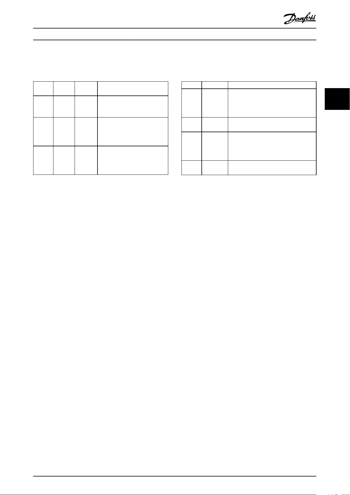
Manual and Software Version
1.3
This manual is regularly reviewed and updated. All
suggestions for improvement are welcome. Table 1.1 shows
the version of the manual and the corresponding software
version.
Manual version Remarks Software version
MG22A1xx Initial release 2.70
Approvals and Certications
1.4
Table 1.2 Approvals and
More approvals and certications are available. Contact the
local Danfoss oce or partner. Drives of voltage T7 (525–
690 V) are UL certied for only 525–600 V.
The drive complies with UL 61800-5-1 thermal memory
retention requirements. For more information, refer to the
section Motor Thermal Protection in the product-specic
design guide.
Certications
NOTICE
IMPOSED LIMITATIONS ON THE OUTPUT
FREQUENCY
From software version 1.99, the output frequency of the
drive is limited to 590 Hz due to export control
regulations.
1.4.1 Compliance with ADN
For compliance with the European Agreement concerning
International Carriage of Dangerous Goods by Inland
Waterways (ADN), refer to ADN-compliant Installation in the
design guide.
Disposal
1.5
Do not dispose of equipment containing
electrical components together with
domestic waste.
Collect it separately in accordance with
local and currently valid legislation.
1 1
Table 1.1 Manual and Software Version
MG22A102 Danfoss A/S © 01/2017 All rights reserved. 3
Page 6
Safety VLT® AQUA Drive FC 202
2 Safety
22
2.1 Safety Symbols
The following symbols are used in this guide:
WARNING
Indicates a potentially hazardous situation that could
result in death or serious injury.
CAUTION
Indicates a potentially hazardous situation that could
result in minor or moderate injury. It can also be used to
alert against unsafe practices.
NOTICE
Indicates important information, including situations that
can result in damage to equipment or property.
2.2 Qualied Personnel
WARNING
UNINTENDED START
When the drive is connected to AC mains, DC supply, or
load sharing, the motor can start at any time.
Unintended start during programming, service, or repair
work can result in death, serious injury, or property
damage. The motor can start with an external switch, a
eldbus command, an input reference signal from the
LCP or LOP, via remote operation using MCT 10 Set-up
Software, or after a cleared fault condition.
To prevent unintended motor start:
Press [O/Reset] on the LCP before
•
programming parameters.
Disconnect the drive from the mains.
•
Completely wire and assemble the drive, motor,
•
and any driven equipment before connecting
the drive to the AC mains, DC supply, or load
sharing.
Correct and reliable transport, storage, installation,
operation, and maintenance are required for the troublefree and safe operation of the drive. Only qualied
personnel are allowed to install or operate this equipment.
Qualied personnel are dened as trained sta, who are
authorized to install, commission, and maintain equipment,
systems, and circuits in accordance with pertinent laws and
regulations. Also, the personnel must be familiar with the
instructions and safety measures described in this manual.
Safety Precautions
2.3
WARNING
HIGH VOLTAGE
Drives contain high voltage when connected to AC mains
input, DC supply, load sharing, or permanent motors.
Failure to use qualied personnel to install, start up, and
maintain the drive can result in death or serious injury.
Only qualied personnel must install, start up,
•
and maintain the drive.
WARNING
DISCHARGE TIME
The drive contains DC-link capacitors, which can remain
charged even when the drive is not powered. High
voltage can be present even when the warning LED
indicator lights are o. Failure to wait 40 minutes after
power has been removed before performing service or
repair work can result in death or serious injury.
Stop the motor.
•
Disconnect AC mains and remote DC-link
•
supplies, including battery back-ups, UPS, and
DC-link connections to other drives.
Disconnect or lock motor.
•
Wait 40 minutes for the capacitors to discharge
•
fully.
Before performing any service or repair work,
•
use an appropriate voltage measuring device to
make sure that the capacitors are fully
discharged.
WARNING
LEAKAGE CURRENT HAZARD
Leakage currents exceed 3.5 mA. Failure to ground the
drive properly can result in death or serious injury.
Ensure the correct grounding of the equipment
•
by a certied electrical installer.
4 Danfoss A/S © 01/2017 All rights reserved. MG22A102
Page 7

Safety Operating Guide
WARNING
EQUIPMENT HAZARD
Contact with rotating shafts and electrical equipment
can result in death or serious injury.
Ensure that only trained and qualied personnel
•
install, start up, and maintain the drive.
Ensure that electrical work conforms to national
•
and local electrical codes.
Follow the procedures in this guide.
•
CAUTION
HOT SURFACES
The drive contains metal components that are still hot
even after the drive has been powered o. Failure to
observe the high temperature symbol (yellow triangle)
on the drive can result in serious burns.
Be aware that internal components, such as
•
busbars, may be extremely hot even after the
drive has been powered o.
Exterior areas marked by the high temperature
•
symbol (yellow triangle) are hot while the drive
is in use and immediately after being powered
o.
2 2
WARNING
INTERNAL FAILURE HAZARD
Under certain circumstances, an internal failure can
cause a component to explode. Failure to keep the
enclosure closed and properly secured can cause death
or serious injury.
Do not operate the drive with the door open or
•
panels o.
Ensure that the enclosure is properly closed and
•
secured during operation.
NOTICE
MAINS SHIELD SAFETY OPTION
A mains shield option is available for enclosures with a
protection rating of IP21/IP 54 (Type 1/Type 12). The
mains shield is a Lexan cover installed inside the
enclosure to protect against the accidental touch of the
power terminals, according to BGV A2, VBG 4.
MG22A102 Danfoss A/S © 01/2017 All rights reserved. 5
Page 8
Product Overview VLT® AQUA Drive FC 202
3 Product Overview
3.1 Intended Use
33
The drive is an electronic motor controller that converts AC mains input into a variable AC waveform output. The frequency
and voltage of the output are regulated to control the motor speed or torque. The drive is designed to:
Regulate motor speed in response to system feedback or to remote commands from external controllers.
•
Monitor system and motor status.
•
Provide motor overload protection.
•
The drive is allowed for use in industrial and commercial environments in accordance with local laws and standards.
Depending on conguration, the drive can be used in standalone applications or form part of a larger system or installation.
NOTICE
In a residential environment, this product can cause radio interference, in which case supplementary mitigation
measures can be required.
Foreseeable misuse
Do not use the drive in applications which are non-compliant with specied operating conditions and environments. Ensure
compliance with the conditions specied in chapter 9 Specications.
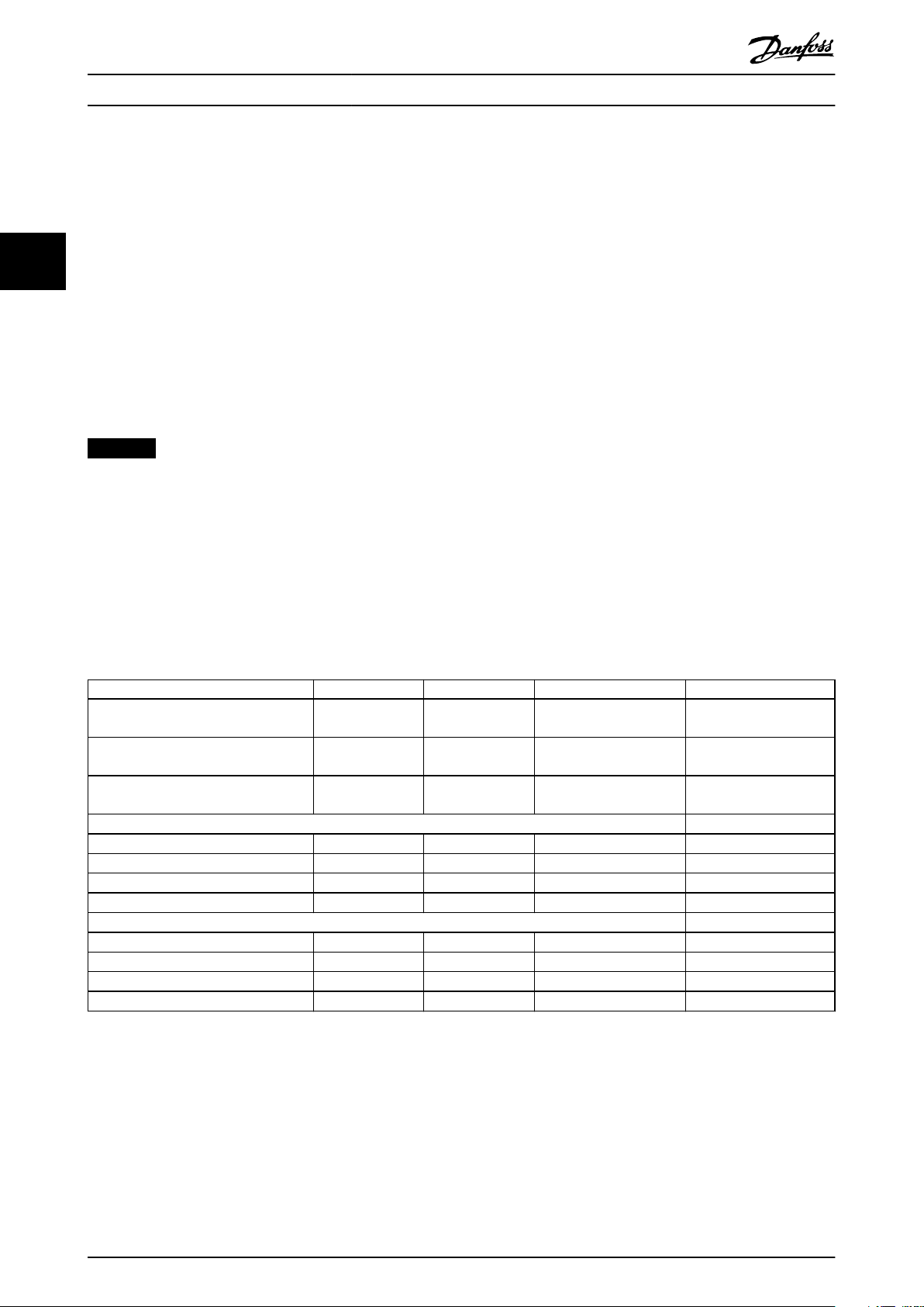
3.2 Power Ratings, Weights, and Dimensions
Table 3.1 provides dimensions for standard congurations. For dimensions on optional congurations, see
chapter 9.8 Enclosure Dimensions.
Enclosure size E1h E2h E3h E4h
Rated power at 380–480 V [kW (hp)] 355–450
(500–600)
Rated power at 525–690 V [kW (hp)] 450–630
(450–650)
Enclosure protection rating IP21/Type 1
IP54/Type 12
Unit dimensions
Height [mm (in)] 2043 (80.4) 2043 (80.4) 1578 (62.1) 1578 (62.1)
Width [mm (in)] 602 (23.7) 698 (27.5) 506 (19.9) 604 (23.89)
Depth [mm (in)] 513 (20.2) 513 (20.2) 482 (19.0) 482 (19.0)
Weight [kg (lb)] 295 (650) 318 (700) 272 (600) 295 (650)
Shipping dimensions
Height [mm (in)] 768 (30.2) 768 (30.2) 746 (29.4) 746 (29.4)
Width [mm (in)] 2191 (86.3) 2191 (86.3) 1759 (69.3) 1759 (69.3)
Depth [mm (in)] 870 (34.3) 870 (34.3) 794 (31.3) 794 (31.3)
Weight [kg (lb)] – – – –
500–560
(650–750)
710–800
(750–950)
IP21/Type 1
IP54/Type 12
355–450
(500–600)
450–630
(450–650)
IP20/
Chassis
500–560
(650–750)
710–800
(750–950)
IP 20/
Chassis
Table 3.1 Enclosure Power Ratings and Dimensions
6 Danfoss A/S © 01/2017 All rights reserved. MG22A102
Page 9
130BF206.11
FASTENER TORQUE:
M10 19Nm (14FT-LB)
M12 35Nm (26FT-LB)
- REGEN 83
FASTENER TORQUE:
M10 19Nm (14FT-LB)
M12 35Nm (26FT-LB)
+ REGEN 82
2
6
4
5
11
12
9
1
7
10
8
3
Product Overview Operating Guide
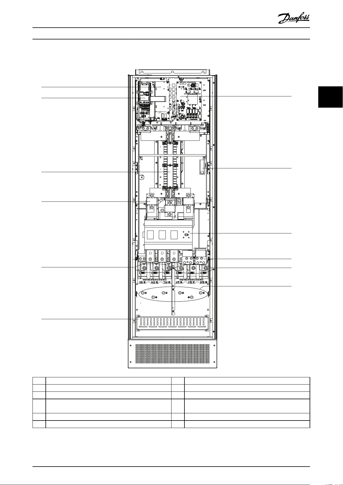
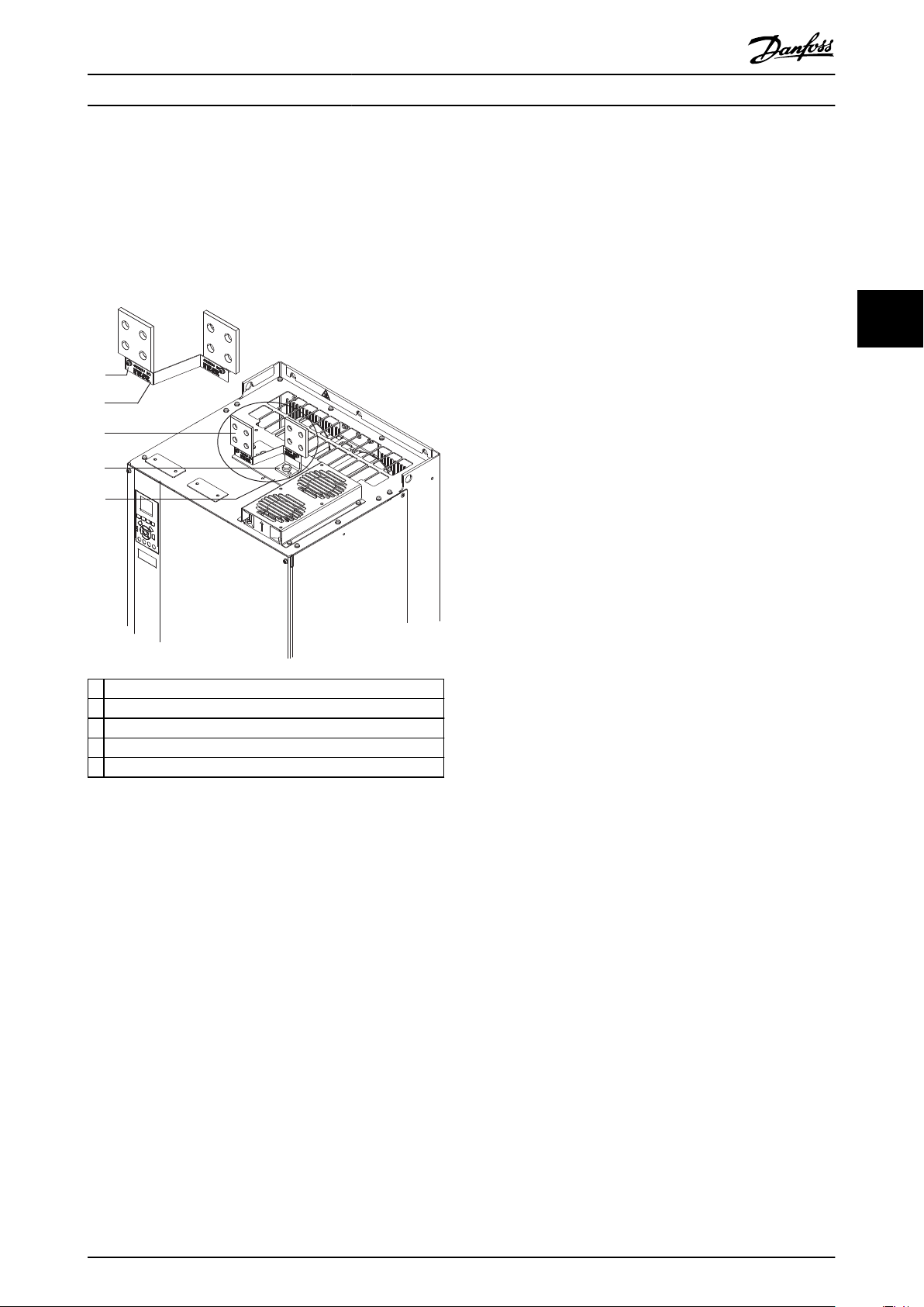
3.3 Interior View of Enclosures E1h and E2h
3 3
1 Control shelf (see Illustration 3.3) 7 Fan power card
2 Local control panel (LCP) cradle 8 Space heater (optional)
3 RFI lter (optional) 9 Mains disconnect (optional)
4 Mains fuses (required for UL compliance, but otherwise
10 Brake/regeneration terminals (optional)
optional)
5 Mains terminals 11 Motor terminals
6 RFI shield termination 12 Ground terminals
Illustration 3.1 Interior View of Enclosure E1h (Enclosure E2h is Similar)
MG22A102 Danfoss A/S © 01/2017 All rights reserved. 7
Page 10
FASTENER TORQUE:
M10 19Nm (14FT-LB)
M12 35Nm (26FT-LB)
+ DC 89
FASTENER TORQUE:
M10 19Nm (14FT-LB)
M12 35Nm (26FT-LB)
- BRAKE 83
FASTENER TORQUE:
M10 19Nm (14FT-LB)
M12 35Nm (26FT-LB)
+ BRAKE 82
FASTENER TORQUE:
M10 19Nm (14FT-LB)
M12 35Nm (26FT-LB)
- DC 88
130BF211.11
1
6
2
5
9
12
13
11
7
8
3
10
4
Product Overview VLT® AQUA Drive FC 202
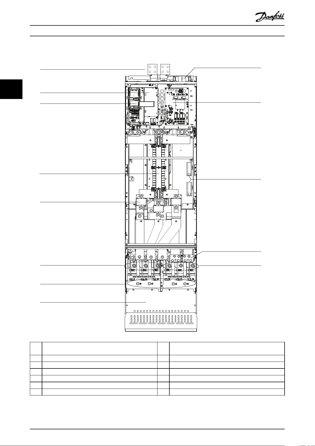
3.4 Interior View of Enclosures E3h and E4h
33
1 Load share/regeneration terminals (optional) 8 RFI shield termination (optional, but is standard when RFI
2 Control shelf (see Illustration 3.3) 9 Fans (used to cool the front section of enclosure)
lter is ordered)
3 Local control panel (LCP) cradle 10 Fan power card
4 RFI lter (optional) 11 Space heater (optional)
5 Mains fuses (optional) 12 Brake terminals (optional)
6 Mains terminals 13 Motor terminals
7 Ground terminals – –
Illustration 3.2 Interior View of Enclosure E3h (Enclosure E4h is Similar)
8 Danfoss A/S © 01/2017 All rights reserved. MG22A102
Page 11
130BF148.11
Remove Jumper to activate Safe Stop
12 13 18 19 27 29 32 33 20 37
39 42 50 53 54 55
61 68 69
1
3
4
12
9
8
RELAY 1 RELAY 2
01 02 0304 05 06
2
6
10
7
5
11
13
Product Overview Operating Guide
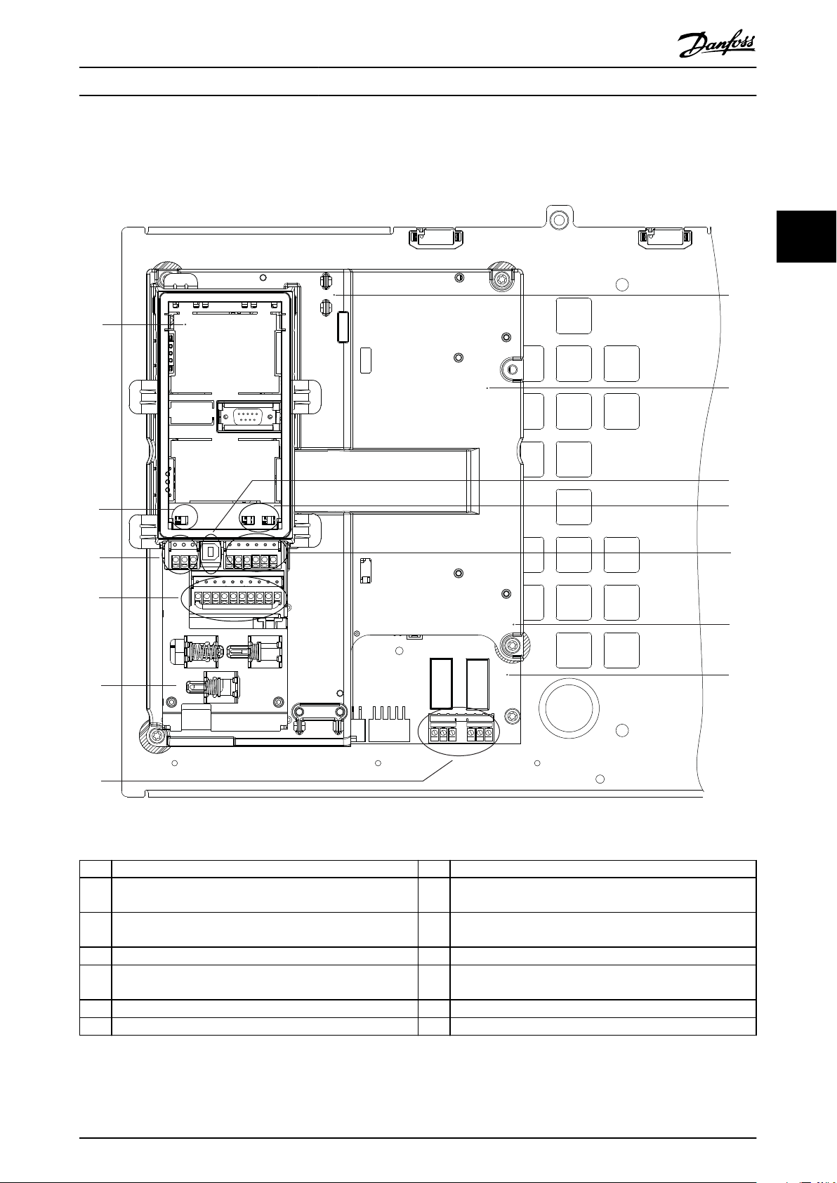
3.5 Control Shelf
3 3
1 LCP cradle (LCP not shown) 8 Control shelf
2 Bus terminal switch
3 Serial communication terminals (see Table 5.1) 10 Analog input switches A53/A54
(see chapter 5.8.5 Conguring RS485 Serial Communication)
4 Digital input/output terminals (see Table 5.2) 11 Analog input/output terminals (see Table 5.3)
5 Cable/EMC clamps 12 Brake resistor terminals, 104–106
6 Relay 1 and relay 2 (see Illustration 5.19) 13 Power card (underneath the control shelf)
7 Control card (underneath LCP and control terminals) – –
9 USB port
(see chapter 5.8.10 Selecting Voltage/Current Input Signal)
(on power card underneath control shelf)
Illustration 3.3 View of Control Shelf
MG22A102 Danfoss A/S © 01/2017 All rights reserved. 9
Page 12
130BF154.10
Auto
on
Reset
Hand
on
O
Status
Quick
Menu
Main
Menu
Alarm
Log
Back
Cancel
Info
OK
Status
1(1)
0.00 A
O Remote Stop
0.0 Hz
On
Alarm
Warn.
0.000
0.000 RPM
0.0000
A1.1
A1.2
A1.3
A2
A3
B1
B2
B4
B3
C1
C2
C3
C4
C5
D1
D2
D3
E1
E2
E3
E4
Product Overview VLT® AQUA Drive FC 202
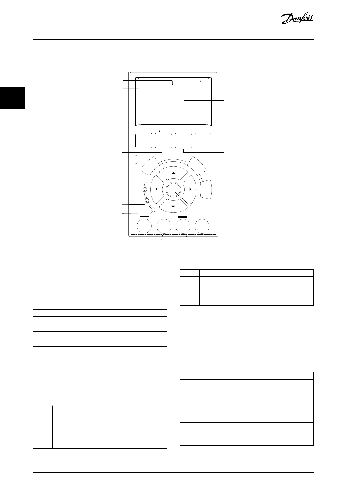
3.6 Local Control Panel (LCP)
33
Illustration 3.4 Graphical Local Control Panel (LCP)
A. Display area
Each display readout has a parameter associated with it.
See Table 3.2. The information shown on the LCP can be
customized for specic applications. Refer to
chapter 6.3.1.2 Q1 My Personal Menu.
Callout Parameter number Default setting
A1.1 0-20 Reference [Unit]
A1.2 0-21 Analog input 53 [V]
A1.3 0-22 Motor current [A]
A2 0-23 Frequency [Hz]
A3 0-24 Feedback [Unit]
Table 3.2 LCP Display Area
B. Menu keys
Menu keys are used to access the menu for setting up
parameters, toggling through status display modes during
normal operation, and viewing fault log data.
Callout Key Function
B1 Status Shows operational information.
B2 Quick Menu Allows access to parameters for initial
set-up instructions. Also provides
detailed application steps. Refer
to chapter 6.3.1.1 Quick Menu Mode.
Callout Key Function
B3 Main Menu Allows access to all parameters. Refer to
chapter 6.3.1.9 Main Menu Mode.
B4 Alarm Log Shows a list of current warnings and the
last 10 alarms.
Table 3.3 LCP Menu Keys
C. Navigation keys
Navigation keys are used for programming functions and
moving the display cursor. The navigation keys also
provide speed control in local (hand) operation. The
display brightness can be adjusted by pressing [Status] and
[▲]/[▼] keys.
Callout Key Function
C1 Back Reverts to the previous step or list in the
menu structure.
C2 Cancel Cancels the last change or command as
long as the display mode has not changed.
C3 Info Shows a denition of the function being
shown.
C4 OK Accesses parameter groups or enables an
option.
C5
▲ ▼
Table 3.4 LCP Navigation Keys
Moves between items in the menu.
◄ ►
10 Danfoss A/S © 01/2017 All rights reserved. MG22A102
Page 13
Product Overview Operating Guide
D. Indicator lights
Indicator lights are used to identify the drive status and to
provide a visual notication of warning or fault conditions.
Callout Indicator Indicator
D1 On Green Activates when the drive receives
D2 Warn. Yellow Activates when warning
D3 Alarm Red Activates during a fault
Table 3.5 LCP Indicator Lights
Function
light
power from the mains voltage or
a 24 V external supply.
conditions are active. Text
appears in the display area
identifying the problem.
condition. Text appears in the
display area identifying the
problem.
E. Operation keys and reset
The operation keys are found toward the bottom of the
local control panel.
Callout Key Function
E1 [Hand on] Starts the drive in local control. An
external stop signal by control input or
serial communication overrides the local
[Hand On].
E2 O Stops the motor but does not remove
power to the drive.
E3 Auto on Puts the system in remote operational
mode so it can respond to an external
start command by control terminals or
serial communication.
E4 Reset Resets the drive manually after a fault has
been cleared.
Table 3.6 LCP Operation Keys and Reset
3 3
MG22A102 Danfoss A/S © 01/2017 All rights reserved. 11
Page 14
Tamb. 55
C/131
F at Full Output Current Derating
IN: 3x525-600V 50/60Hz 743/711 A (UL)
OUT: MOTOR 3x0-Vin 0-500Hz 763/730 A
IN: 3x525-690V 50/60Hz 743/711 A (CE)
710 kW / 750 HP, High Overload
OUT: MOTOR 3x0-Vin 0-500Hz 889/850 A
IN: 3x525-690V 50/60Hz 866/828 A (CE)
800 kW / 950 HP, Normal Overload
VLT
T/C: FC-202N710T7E21H2XGC7XKSXXXXA0BXCXXXXD0
P/N: 131N2885 S/N:
R
AQUA Drive
www.danfoss.com
130BF712.10
IN: 3x525-690V 50/60Hz 866/828 A (UL)
ASSEMBLED IN USA
Tamb. 45
C/113
F at Full Output Current
IP21 / TYPE 1
SCCR 100 kA at UL Voltage range 525-600 V
Listed 36U0 E70524 IND. CONT. EQ.
UL Voltage range 525-600 V
CAUTION - ATTENTION:
Stored charge, wait 40 min.
Charge residuelle, attendez 40
See manual for special condition / prefuses
Voir manuel de conditions speciales / fusibles
WARNING - AVERTISSEMENT:
`
`
123456H123
1
2
3
4
5
6
Danfoss A/S
6340 Nordborg
Denmark
Mechanical Installation VLT® AQUA Drive FC 202
4 Mechanical Installation
4.1 Items Supplied
Items supplied can vary according to product congu-
ration.
4.2 Tools Needed
Receiving/unloading
I-beam and hooks rated to lift the weight of the
•
drive. Refer to chapter 3.2 Power Ratings, Weights,
Make sure that the items supplied and the
44
•
information on the nameplate correspond to the
order conrmation.
Visually check the packaging and the drive for
•
damage caused by inappropriate handling during
Installation
shipment. File any claim for damage with the
carrier. Retain damaged parts for clarication.
and Dimensions.
Crane or other lifting aid to place the unit into
•
position.
Drill with 10 mm or 12 mm drill bits.
•
Tape measurer.
•
Various sizes of Phillips and at bladed
•
screwdrivers.
Wrench with relevant metric sockets (7–17 mm).
•
Wrench extensions.
•
Torx drives (T25 and T50).
•
Sheet metal punch for conduits or cable glands.
•
I-beam and hooks to lift the weight of the drive.
•
Refer to chapter 3.2 Power Ratings, Weights, and
Dimensions.
Crane or other lifting aid to place the drive onto
•
pedestal and into position.
Storage
4.3
Store the drive in a dry location. Keep the equipment
sealed in its packaging until installation. Refer to
chapter 9.4 Ambient Conditions for recommended ambient
temperature.
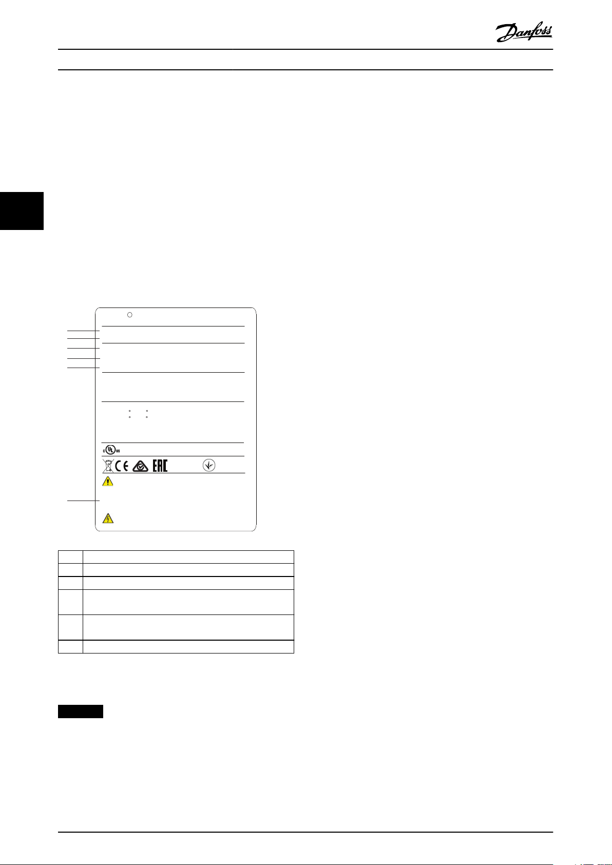
1 Type code
2 Code number
3 Power rating
Input voltage, frequency, and current (at low/high
4
voltages)
Output voltage, frequency, and current (at low/high
5
voltages)
6 Discharge time
Illustration 4.1 Product Nameplate for E2h Enclosure (Example)
NOTICE
Removing the nameplate from the drive can result in the
loss or warranty.
Periodic forming (capacitor charging) is not necessary
during storage unless storage exceeds 12 months.
12 Danfoss A/S © 01/2017 All rights reserved. MG22A102
Page 15
Mechanical Installation Operating Guide
4.4 Operating Environment
In environments with airborne liquids, particles, or
corrosive gases, ensure that the IP/Type rating of the
equipment matches the installation environment. For
specications regarding ambient conditions, see
chapter 9.4 Ambient Conditions.
NOTICE
CONDENSATION
Moisture can condense on the electronic components
and cause short circuits. Avoid installation in areas
subject to frost. Install an optional space heater when
the drive is colder than the ambient air. Operating in
standby mode reduces the risk of condensation as long
as the power dissipation keeps the circuitry free of
moisture.
NOTICE
EXTREME AMBIENT CONDITIONS
Hot or cold temperatures compromise unit performance
and longevity.
Do not operate in environments where the
•
ambient temperature exceeds 55 °C (131 °F).
The drive can operate at temperatures down to
•
-10 °C (14 °F). However, proper operation at
rated load is only guaranteed at 0 °C (32 °F) or
higher.
Extra air conditioning of the cabinet or instal-
•
lation site is required if temperature exceeds
ambient temperature limits.
4.4.1 Gases
Aggressive gases, such as hydrogen sulphide, chlorine, or
ammonia can damage the electrical and mechanical
components. The unit uses conformal-coated circuit boards
to reduce the eects of aggressive gases. For conformalcoating class specications and ratings, see
chapter 9.4 Ambient Conditions.
4.4.2 Dust
When installing the drive in dusty environments, pay
attention to the following:
Periodic maintenance
When dust accumulates on electronic components, it acts
as a layer of insulation. This layer reduces the cooling
capacity of the components, and the components become
warmer. The hotter environment decreases the life of the
electronic components.
Keep the heat sink and fans free from dust buildup. For
more service and maintenance information, refer to
chapter 8 Maintenance, Diagnostics, and Troubleshooting.
Cooling fans
Fans provide airow to cool the drive. When fans are
exposed to dusty environments, the dust can damage the
fan bearings and cause premature fan failure. Dust also can
accumulate on fan blades causing an imbalance which
prevents the fans from properly cooling the unit.
4.4.3 Potentially Explosive Atmospheres
WARNING
EXPLOSIVE ATMOSPHERE
Do not install the drive in a potentially explosive
atmosphere. Install the unit in a cabinet outside of this
area. Failure to follow this guideline increases risk of
death or serious injury.
Systems operated in potentially explosive atmospheres
must fulll special conditions. EU Directive 94/9/EC (ATEX
95) classies the operation of electronic devices in
potentially explosive atmospheres.
species that if a spark occurs, it is
Class d
•
contained in a protected area.
Class e prohibits any occurrence of a spark.
•
Motors with class d protection
Does not require approval. Special wiring and containment
are required.
Motors with class e protection
When combined with an ATEX approved PTC monitoring
device like the VLT® PTC Thermistor Card MCB 112, installation does not need an individual approval from an
approbated organization.
Motors with class d/e protection
The motor itself has an e ignition protection class, while
the motor cabling and connection environment is in
compliance with the d
peak voltage, use a sine-wave lter at the drive output.
When using a drive in a potentially explosive
atmosphere, use the following:
Motors with ignition protection class d or e.
•
PTC temperature sensor to monitor the motor
•
temperature.
Short motor cables.
•
Sine-wave output lters when shielded motor
•
cables are not used.
classication. To attenuate the high
4 4
MG22A102 Danfoss A/S © 01/2017 All rights reserved. 13
Page 16
Mechanical Installation VLT® AQUA Drive FC 202
Duct cooling
NOTICE
MOTOR THERMISTOR SENSOR MONITORING
VLT® AutomationDrive units with the VLT® PTC
Thermistor Card MCB 112 option are PTB-certied for
potentially explosive atmospheres.
4.5 Installation and Cooling Requirements
44
NOTICE
Improper mounting can result in overheating and
reduced performance.
Installation requirements
Locate the unit as near to the motor as possible.
•
See chapter 9.5 Cable Specications for the
maximum motor cable length.
Ensure unit stability by mounting the unit to a
•
solid surface.
Enclosures E3h and E4h can be mounted:
•
- Vertically on the back plate of the panel
(typical installation).
- Vertically upside down on the back
plate of the panel.
- Horizontally on its back, mounted on
the back plate of the panel.
- Horizontally on its side, mounted on
oor of the panel.
Ensure that the strength of the mounting location
•
supports the unit weight.
Ensure that there is enough space around the
•
unit for proper cooling. Refer to
chapter 9.9 Enclosure Airow.
Ensure enough access to open the door.
•
Ensure cable entry from the bottom.
•
1) For non-typical installation, contact the factory.
Cooling requirements
Ensure that top and bottom clearance for air
•
cooling is provided. Clearance requirement:
225 mm (9 in).
Provide
•
Consider derating for temperatures starting
•
between 45 °C (113 °F) and 50 °C (122 °F) and
elevation 1000 m (3300 ft) above sea level. See
the design guide for detailed information.
The drive utilizes a back-channel cooling concept that
removes heat sink cooling air. The heat sink cooling air
carries approximately 90% of the heat out of the back
channel of the drive. Redirect the back-channel air from
the panel or room by using:
sucient airow ow rate. See Table 4.1.
1)
1)
1)
•
Back-channel cooling kits are available to direct
the heat sink cooling air out of the panel when
IP20/Chassis drives are installed in Rittal
enclosures. Use of these kits reduce the heat in
the panel and smaller door fans can be specied.
Back-wall cooling
•
Installing top and base covers to the unit allows
the back-channel cooling air to be ventilated out
of the room.
NOTICE
For E3h and E4h enclosures (IP20/Chassis), at least 1
door fan is required on the enclosure to remove the heat
not contained in the back-channel of the drive. It also
removes any additional losses generated by other
components inside the drive. To select the appropriate
fan size, calculate the total required airow.
Secure the necessary airow over the heat sink.
Frame Door fan/top fan
[m3/hr (cfm)]
E1h 510 (300) 994 (585)
E2h 552 (325) 1053–1206 (620–710)
E3h 595 (350) 994 (585)
E4h 629 (370) 1053–1206 (620–710)
Table 4.1 Airow Rate
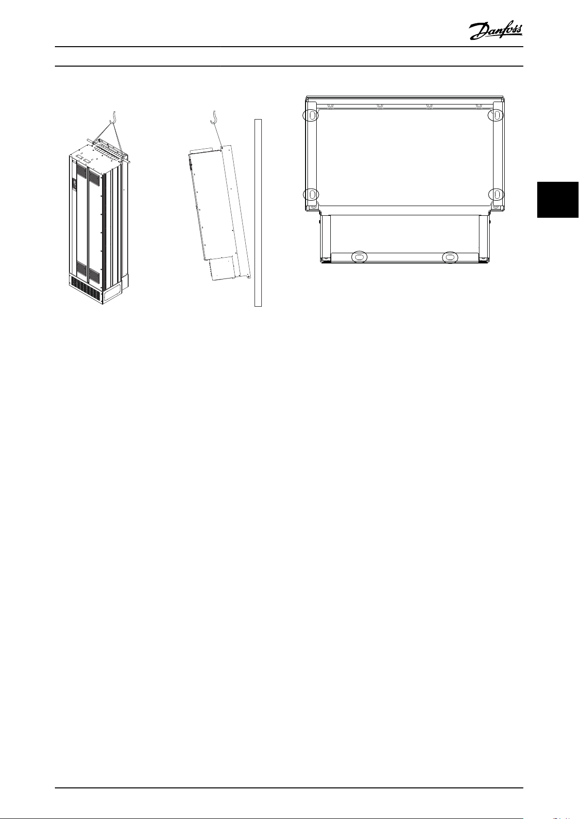
Lifting the Unit
4.6
Lifting
Always lift the drive using the dedicated lifting eyes. To
avoid bending the lifting holes, use a bar.
Heat sink fan
[m3/hr (cfm)]
WARNING
RISK OF INJURY OR DEATH
Follow local safety regulations for lifting heavy weights.
Failure to follow recommendations and local safety
regulations can result in death or serious injury.
Ensure that the lifting equipment is in proper
•
working condition.
See chapter 3.2 Power Ratings, Weights, and
•
Dimensions for the weight of the dierent
enclosure types.
Maximum diameter for bar: 20 mm (0.8 in).
•
The angle from the top of the drive to the
•
lifting cable: 60° or greater.
14 Danfoss A/S © 01/2017 All rights reserved. MG22A102
Page 17
130BF685.10
130BF208.10
Mechanical Installation Operating Guide
4 4
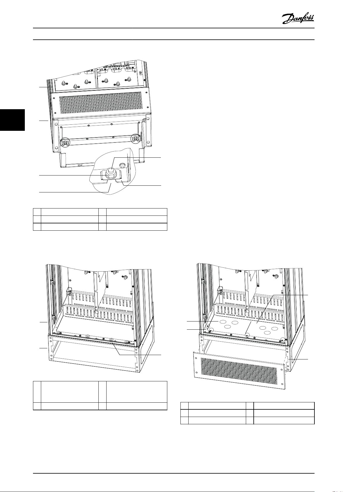
Illustration 4.3 Pedestal to Floor Mounting Points
4.7.2 Attaching the E1h/E2h to the Pedestal
Illustration 4.2 Recommended Lifting Method
4.7 E1h/E2h Mechanical Installation
The E1h and E2h enclosure size is intended only for oor
installation, and is shipped with a pedestal and a gland
plate. The pedestal and gland plate must be installed for
proper installation.
The pedestal is 200 mm (7.9 in) and has an opening in the
front to allow airow necessary to cool the power
components of the drive.
The gland plate is necessary to provide cooling air to the
control components of the drive via the door fan, and to
maintain the IP21/Type 1 or IP54/Type 12 protection rating.
4.7.1 Securing the Pedestal to the Floor
The pedestal must be secured to the oor using 6 bolts
before installing the enclosure.
1. Determine proper placement of the unit,
concerning operating conditions and cable
access.
2. Access the mounting holes by removing the front
panel of the pedestal.
3. Set the pedestal on the oor and secure using 6
bolts through the mounting holes. Refer to the
circled areas in Illustration 4.3.
1. Lift the drive and position it on the pedestal.
There are 2 bolts in the rear of the pedestal that
slide into the 2 slotted holes in the rear of the
enclosure. Position the drive by adjusting the
bolts up or down. Loosely secure with 2 M10 nuts
and locking brackets. See Illustration 4.4.
2. Verify that there is 225 mm (9 in) top clearance
for air exhaust.
3. Verify that the air intake at the bottom front of
the unit is not obstructed.
4. Around the top of the pedestal, secure the
enclosure using 6 M10x30 fasteners. Refer to
Illustration 4.5. Loosely tighten each bolt until all
bolts are installed.
5. Fasten each bolt securely and torque to 19 Nm
(169 in-lb).
6. Torque the 2 M10 nuts at the rear of the
enclosure to 19 Nm (169 in-lb).
MG22A102 Danfoss A/S © 01/2017 All rights reserved. 15
Page 18
130BF225.10
1
2
5
4
6
3
130BF207.10
1
2
3
130BF209.10
1
3
4
2
Mechanical Installation VLT® AQUA Drive FC 202
4.7.3 Creating Cable Openings
The gland plate is a sheet of metal with studs along the
outer edge. The gland plate provides cable entry and cable
termination points, and must be installed to maintain the
IP21/IP54 (Type 1/Type 12) protection rating. The plate is
placed between the drive enclosure and the pedestal.
Depending on stud orientation, the plate can be installed
from inside the enclosure or the pedestal. For gland plate
44
1 Enclosure 4 Slotted hole in enclosure
2 Pedestal 5 Bolt at rear of pedestal
3 M10 nut 6 Locking bracket
Illustration 4.4 Pedestal to Enclosure Back Mounting Points
dimensions, see chapter 9.8.1 E1h Exterior Dimensions.
Refer to Illustration 4.6 for the following steps.
1. Create cable entry holes in the gland plate using
a sheet metal punch.
2. Insert the gland plate using 1 of the following
methods:
2a To insert the gland plate through the
pedestal, slide the gland plate through
the slot (4) in the front of the pedestal.
2b To insert the gland plate through the
enclosure, angle the gland plate until it
can be slid under the slotted brackets.
3. Align the studs on the gland plate to the holes in
the pedestal and secure with 10 M5 nuts (2).
4. Torque each nut to 2.3 Nm (20 in-lb).
1 Enclosure 3 M10x30 fasteners
(rear corner bolts not
shown)
2 Pedestal – –
Illustration 4.5 Pedestal to Enclosure Mounting Points
16 Danfoss A/S © 01/2017 All rights reserved. MG22A102
1 Cable entry hole 4 Slot in pedestal base
2 M5 nut 5 Front cover/grill
3 Gland plate – –
Illustration 4.6 Installing the Gland Plate
Page 19
1
130BF662.10
2
Mechanical Installation Operating Guide
4.8 E3h/E4h Mechanical Installation
The E3h and E4h enclosure sizes are intended to be
mounted on a wall or on a mounting panel within an
enclosure. A plastic gland plate is installed on the
enclosure. It is designed to prevent unintentional access to
the terminals in an IP20/protected chasis unit.
NOTICE
Regeneration/Load share Option
Due to the exposed terminals at the top of the
enclosure, units with the regeneration/load share option
have an IP00 protection rating.
4.8.1 Attaching the E3h/E4h to a Mounting
Plate or Wall
1. Drill the mounting holes according to the
enclosure size. Refer to chapter 9.8 Enclosure
Dimensions.
2. Secure the top of the drive enclosure to the
mounting plate or wall.
3. Secure the base of the drive enclosure to the
mounting plate or wall.
3. Based on the measurement and positions of the
cables, create openings in the plastic gland plate
by cutting out the necessary squares.
4. Slide the plastic gland plate (7) onto the bottom
rails of the terminal cover.
5. Tilt the front of the terminal cover downward
until the fastener points (8) rest on the slotted
drive brackets (6).
6. Make sure the side panels of the terminal cover
are on the outside track guide (5).
7. Push the terminal cover until it is up against the
slotted drive bracket.
8. Tilt the front of the terminal cover upward until
the fastener hole in the bottom of the drive
aligns with the keyhole opening (9) in the
terminal. Secure with 2 T25 screws and torque to
2.3 Nm (20 in-lb).
9. Secure the bottom panel with 3 T25 screws and
torque to 2.3 Nm (20 in-lb).
4 4
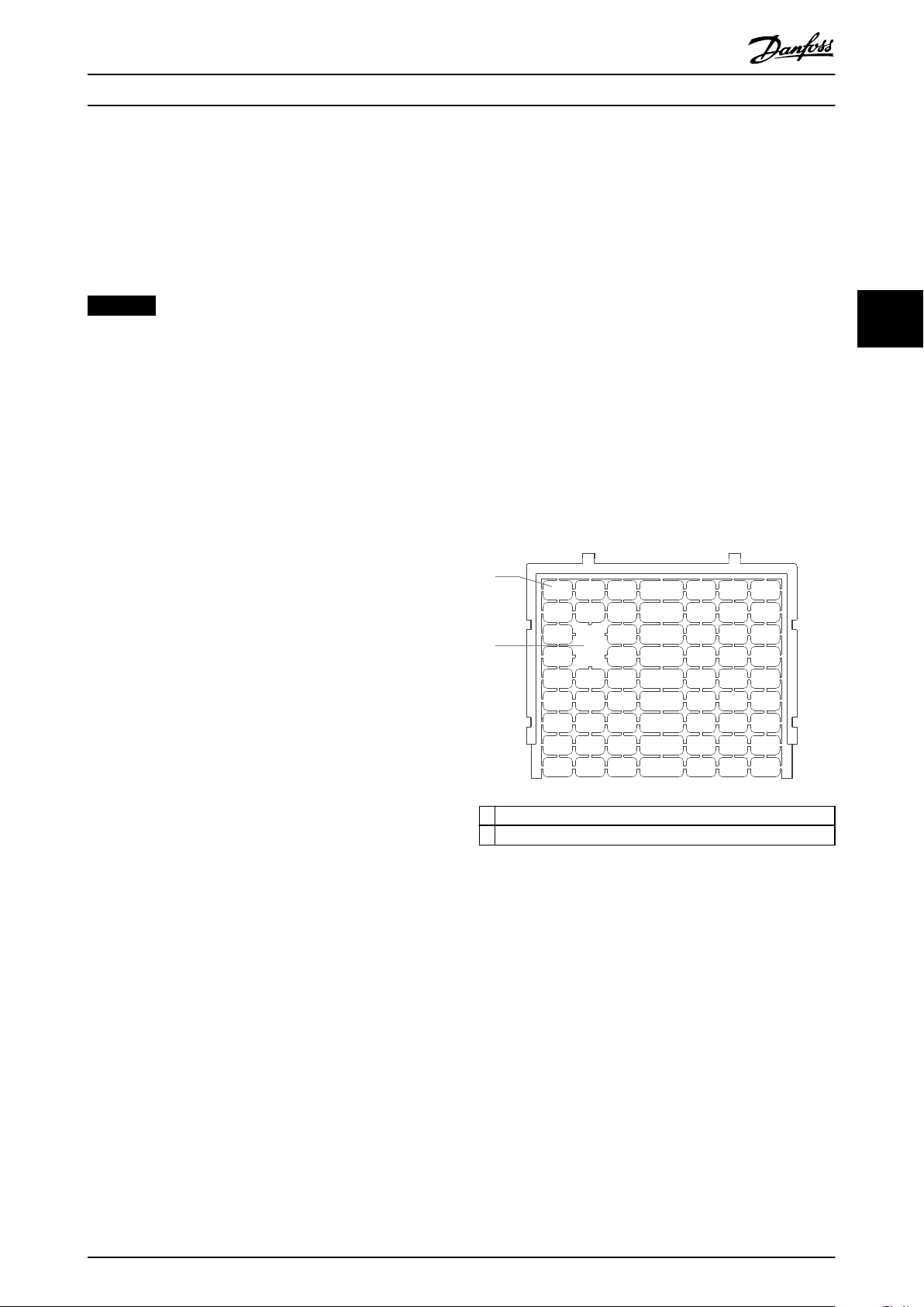
4.8.2 Creating Cable Openings
The gland plate covers the bottom part of the drive
enclosure and must be installed to maintain the IP20/
Chassis protection rating. The gland plate consists of
plastic squares that can be cut out to provide cable access
to the terminals. See Illustration 4.7.
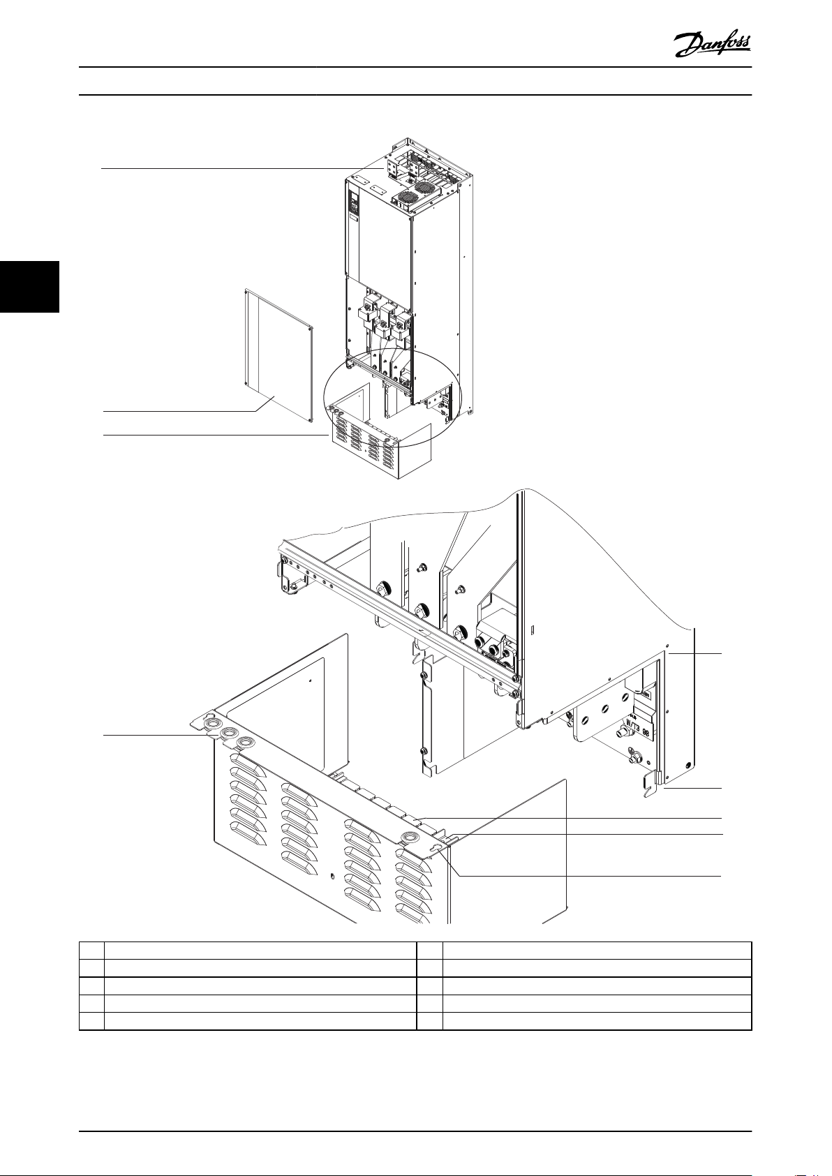
1. Remove the bottom panel and terminal cover.
See Illustration 4.8.
1a Detach the bottom panel by removing 4
T25 screws.
1b Remove 5 T20 screws that secure the
bottom of the drive to the top of the
terminal cover, and then pull the
terminal cover straight out.
2. Determine the size and position of the motor,
mains, and ground cables. Note their position and
measurements.
1 Plastic square
2 Squares removed for cable access
Illustration 4.7 Plastic Gland Plate
MG22A102 Danfoss A/S © 01/2017 All rights reserved. 17
Page 20
6
7
9
5
8
4
130BF688.10
2
3
1
Mechanical Installation VLT® AQUA Drive FC 202
44
1 Load share/regeneration terminals (optional) 6 Slotted drive bracket
2 Bottom panel 7 Plastic gland plate (installed)
3 Terminal cover 8 Fastener point
4 Grommet access hole for control wiring 9 Keyhole opening
5 Track guide – –
Illustration 4.8 Assembling the Gland Plate and Terminal Cover
18 Danfoss A/S © 01/2017 All rights reserved. MG22A102
Page 21
130BF697.10
3
5
4
1
2
Mechanical Installation Operating Guide
4.8.3 Installing Load share/Regeneration
Terminals
The load share/regeneration terminals, located on the top
of the drive, are not installed from the factory to prevent
damage during shipping. Refer to Illustration 4.9 for the
following steps.
4 4
1 Label fastener, M4
2 Label
3 Load share/regeneration terminal
4 Terminal fastener, M10
5 Terminal plate with 2 openings
Illustration 4.9 Load share/Regeneration Terminals
1. Remove the terminal plate, 2 terminals, label, and
fasteners from the accessory bag included with
the drive.
2. Remove the cover from the load share/
regeneration opening on the top of the drive. Put
aside the 2 M5 fasteners for reuse later.
3. Remove the plastic backing and install the
terminal plate over the load share/regeneration
opening. Secure with the 2 M5 fasteners and
torque to 2.3 Nm (20 in-lb).
4. Install the both terminals to the terminal plate
using 1 M10 fastener per terminal. Torque to 19
Nm (169 in-lb).
5. Install the label on the front of the terminals as
shown in Illustration 4.9. Secure with 2 M4 screws
and torque to 1.2 Nm (10 in-lb).
MG22A102 Danfoss A/S © 01/2017 All rights reserved. 19
Page 22
Electrical Installation VLT® AQUA Drive FC 202
5 Electrical Installation
5.1 Safety Instructions
See chapter 2 Safety for general safety instructions.
WARNING
INDUCED VOLTAGE
Induced voltage from output motor cables from dierent
drives that are run together can charge equipment
55
capacitors even with the equipment turned o and
locked out. Failure to run output motor cables separately
or use shielded cables could result in death or serious
injury.
Run output motor cables separately, or
•
Use shielded cables.
•
Simultaneously lock out all the drives.
•
WARNING
SHOCK HAZARD
The drive can cause a DC current in the ground
conductor and thus result in death or serious injury.
When a residual current-operated protective
•
device (RCD) is used for protection against
electrical shock, only an RCD of Type B is
allowed on the supply side.
Failure to follow the recommendation means that the
RCD cannot provide the intended protection.
CAUTION
PROPERTY DAMAGE!
Protection against motor overload is not included in the
default setting. To add this function, set
parameter 1-90 Motor Thermal Protection to [ETR trip] or
[ETR warning]. For the North American market, the ETR
function provides class 20 motor overload protection in
accordance with NEC. Failure to set parameter 1-90 Motor
Thermal Protection to [ETR trip] or [ETR warning] means
that motor overload protection is not provided and
property damage can occur if the motor overheats.
5.2 EMC-compliant Installation
To obtain an EMC-compliant installation, follow the
instructions provided in:
chapter 5.3 Wiring Schematic.
•
chapter 5.4 Connecting the Motor.
•
chapter 5.6 Connecting to Ground.
•
chapter 5.8 Control Wiring.
•
NOTICE
TWISTED SHIELD ENDS (PIGTAILS)
Twisted shield ends increase the shield impedance at
higher frequencies, which reduces the shield eect and
increases the leakage current. Avoid twisted shield ends
by using integrated shield clamps.
Overcurrent protection
Extra protective equipment such as short-circuit
•
protection or motor thermal protection between
drive and motor is required for applications with
multiple motors.
Input fusing is required to provide short circuit
•
and overcurrent protection. If fuses are not
factory-supplied, the installer must provide them.
See maximum fuse ratings in chapter 9.7 Fuses.
Wire type and ratings
All wiring must comply with local and national
•
regulations regarding cross-section and ambient
temperature requirements.
Power connection wire recommendation:
•
Minimum 75 °C (167 °F) rated copper wire.
See chapter 9.5.1 Cable Specications for recommended
wire sizes and types.
For use with relays, control cables, a signal
•
interface, eldbus, or brake, connect the shield to
the enclosure at both ends. If the ground path
has high impedance, is noisy, or is carrying
current, break the shield connection on 1 end to
avoid ground current loops.
Convey the currents back to the unit using a
•
metal mounting plate. Ensure good electrical
contact from the mounting plate through the
mounting screws to the drive chassis.
Use shielded cables for motor output cables. An
•
alternative is unshielded motor cables within
metal conduit.
NOTICE
SHIELDED CABLES
If shielded cables or metal conduits are not used, the
unit and the installation does not meet regulatory limits
on radio frequency (RF) emission levels.
20 Danfoss A/S © 01/2017 All rights reserved. MG22A102
Page 23

Electrical Installation Operating Guide
Ensure that motor and brake cables are as short
•
as possible to reduce the interference level from
the entire system.
Avoid placing cables with a sensitive signal level
•
alongside motor and brake cables.
For communication and command/control lines,
•
follow the particular communication protocol
standards. For example, USB must use shielded
cables, but RS-485/ethernet can use shielded UTP
or unshielded UTP cables.
Ensure that all control terminal connections are
•
PELV.
NOTICE
EMC INTERFERENCE
Use shielded cables for motor and control wiring, and
separate cables for mains input, motor wiring, and
control wiring. Failure to isolate power, motor, and
control cables can result in unintended behavior or
reduced performance. Minimum 200 mm (7.9 in)
clearance between mains input, motor, and control
cables is required.
5 5
NOTICE
INSTALLATION AT HIGH ALTITUDE
There is a risk for overvoltage. Isolation between
components and critical parts could be insucient, and
may not comply with PELV requirements. Reduce the risk
for overvoltage by using external protective devices or
galvanic isolation.
For installations above 2000 m (6500 ft) altitude, contact
Danfoss regarding PELV compliance.
NOTICE
PELV COMPLIANCE
Prevent electric shock by using protective extra low
voltage (PELV) electrical supply and complying with local
and national PELV regulations.
MG22A102 Danfoss A/S © 01/2017 All rights reserved. 21
Page 24
130BF228.10
L1
L2
L3
PE
PE
u
v
w
2
1
3
5
16
17
18
14
12
8
7
10
9
4
11
13
4
4
6
15
90
55
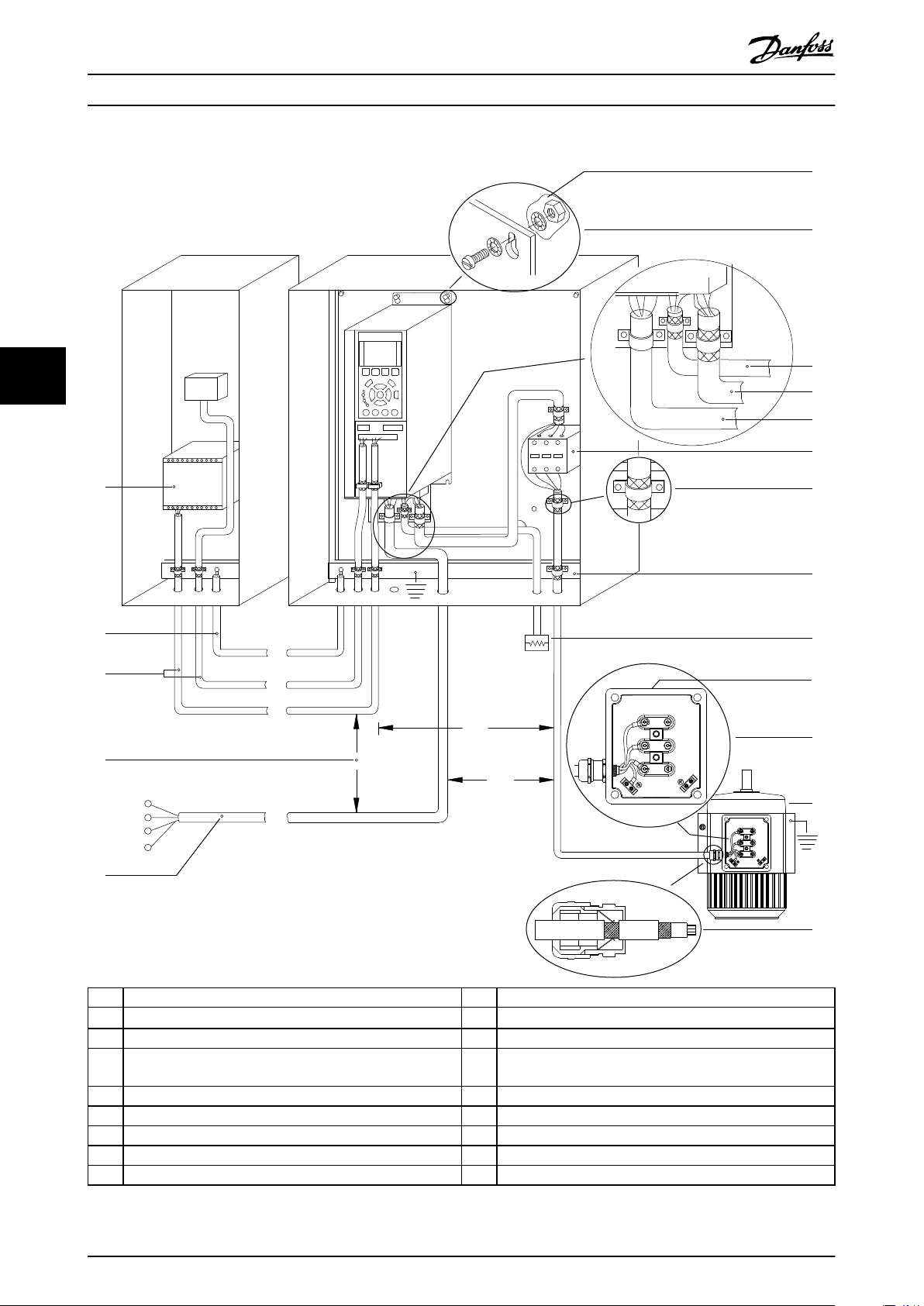
Electrical Installation VLT® AQUA Drive FC 202
1 PLC 10 Mains cable (unshielded)
2
Minimum 16 mm2 equalizing cable
3 Control cables 12 Cable insulation stripped
4 Minimum 200 mm between control cables, motor cables, and
mains cables.
5 Mains supply 14 Brake resistor
6 Bare (unpainted) surface 15 Metal box
7 Star washers 16 Connection to motor
8 Brake cable (shielded) 17 Motor
9 Motor cable (shielded) 18 EMC cable gland
11 Output contactor, and so on
13 Common ground busbar. Follow local and national
requirements for cabinet grounding.
Illustration 5.1 Example of Proper EMC Installation
22 Danfoss A/S © 01/2017 All rights reserved. MG22A102
Page 25
130BF111.11
230 V AC
50/60 Hz
TB5
R1
Regen +
Regen -
83
Regen (optional)
1
2
Brake temperature
(NC)
Space heater (optional)
91 (L1)
92 (L2)
93 (L3)
PE
88 (-)
89 (+)
50 (+10 V OUT)
53 (A IN)
54 (A IN)
55 (COM A IN)
0/4-20 mA
12 (+24 V OUT)
13 (+24 V OUT)
18 (D IN)
20 (COM D IN)
15 mA
200 mA
(U) 96
(V) 97
(W) 98
(PE) 99
(COM A OUT) 39
(A OUT) 42
0/4-20 mA
03
+10 V DC
-10 V DC - +10 V DC
0/4-20 mA
24 V DC
02
01
05
04
06
240 V AC, 2A
24 V (NPN)
0 V (PNP)
0 V (PNP)
24 V (NPN)
19 (D IN)
24 V (NPN)
0 V (PNP)
27
24V
0V
(D IN/OUT)
0 V (PNP)
24 V (NPN)
(D IN/OUT)
0V
24V
29
24 V (NPN)
0 V (PNP)
0 V (PNP)
24 V (NPN)
33 (D IN)
32 (D IN)
1 2
ON
A53 U-I (S201)
ON
21
A54 U-I (S202)
ON=0-20 mA
OFF=0-10 V
95
400 V AC, 2A
P 5-00
(R+) 82
(R-) 81
37 (D IN)
1)
+ - + -
(P RS485) 68
(N RS485) 69
(COM RS485) 61
0V
5V
S801
RS485
RS485
21
ON
S801/Bus Term.
OFF-ON
3-phase
power
input
Load share
Switch mode
power supply
Motor
Analog output
interface
Relay1
Relay2
ON=Terminated
OFF=Open
Brake
resistor
(NPN) = Sink
(PNP) = Source
= ==
240 V AC, 2A
400 V AC, 2A
-10 V DC - +10 V DC
10 V DC
(optional)
(optional)
Electrical Installation Operating Guide
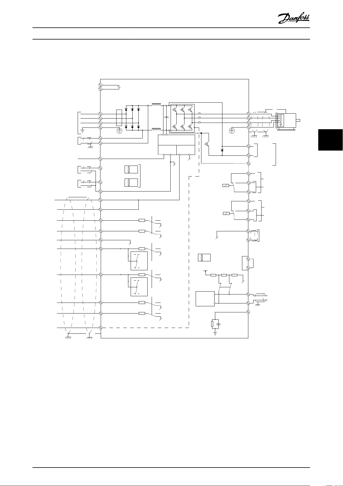
5.3 Wiring Schematic
5 5
Illustration 5.2 Basic Wiring Schematic
A=Analog, D=Digital
1) Terminal 37 (optional) is used for Safe Torque O. For Safe Torque O installation instructions, refer to the Safe Torque O
Operating Guide.
MG22A102 Danfoss A/S © 01/2017 All rights reserved. 23
Page 26

Electrical Installation VLT® AQUA Drive FC 202
5.4 Connecting the Motor
WARNING
INDUCED VOLTAGE
Induced voltage from output motor cables that run together can charge equipment capacitors, even with the
equipment turned o and locked out. Failure to run output motor cables separately or use shielded cables could result
in death or serious injury.
Comply with local and national electrical codes for cable sizes. For maximum wire sizes, see chapter 9.1 Electrical
•
Data.
Follow motor manufacturer wiring requirements.
55
•
Motor wiring knockouts or access panels are provided on the pedestal of IP21/IP54 (Type 1/Type 12) units.
•
Do not wire a starting or pole-changing device (for example Dahlander motor or slip ring asynchronous motor)
•
between the drive and the motor.
Procedure
1. Strip a section of the outer cable insulation.
2. Establish mechanical xation and electrical contact between the cable shield and ground by positioning the
stripped wire under the cable clamp.
3. Connect the ground wire to the nearest grounding terminal in accordance with the grounding instructions
provided in chapter 5.6 Connecting to Ground.
4. Connect the 3-phase motor wiring to terminals 96 (U), 97 (V), and 98 (W), see Illustration 5.3.
5. Tighten the terminals in accordance with the information provided in chapter 9.10.1 Fastener Torque Ratings.
24 Danfoss A/S © 01/2017 All rights reserved. MG22A102
Page 27
130BF150.10
U/T1 96 V/T2 97
W/T3 98
FASTENER TORQUE M10 19Nm (14FT-LB), M12 35Nm (26FT-LB)
U/T1 96 V/T2 97
W/T3 98
FASTENER TORQUE M10 19Nm (14FT-LB), M12 35Nm (14FT-LB)
+ REGEN 82
FASTENER TORQUE:
M10 19Nm (14FT-LB)
M12 35Nm (26FT-LB)
- REGEN 83
FASTENER TORQUE:
M10 19Nm (14FT-LB)
M12 35Nm (26FT-LB)
Electrical Installation Operating Guide
5 5
Illustration 5.3 AC motor terminals (E1h shown). For a detailed view of terminals, refer to chapter 5.7 Terminal Dimensions.
MG22A102 Danfoss A/S © 01/2017 All rights reserved. 25
Page 28

Electrical Installation VLT® AQUA Drive FC 202
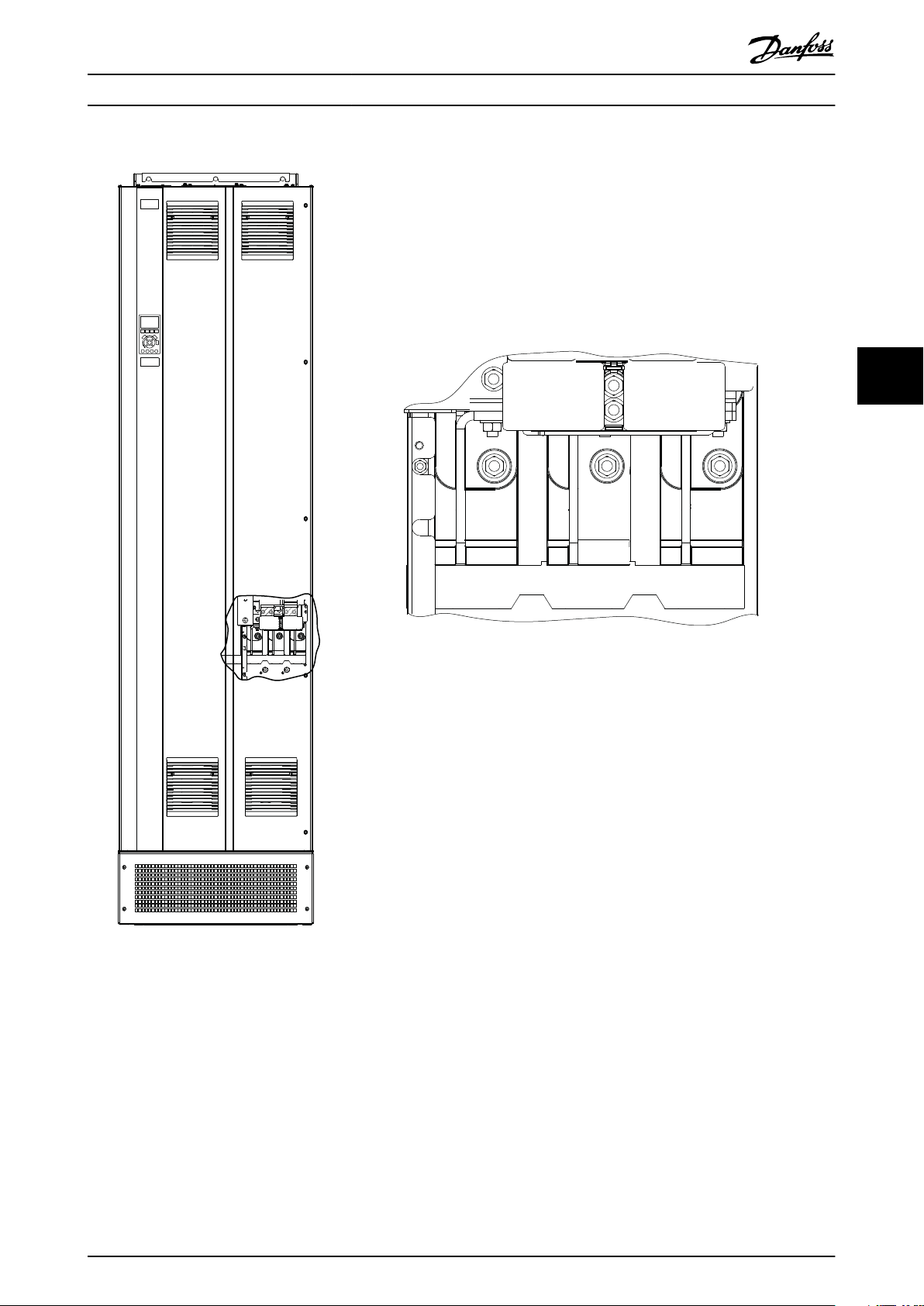
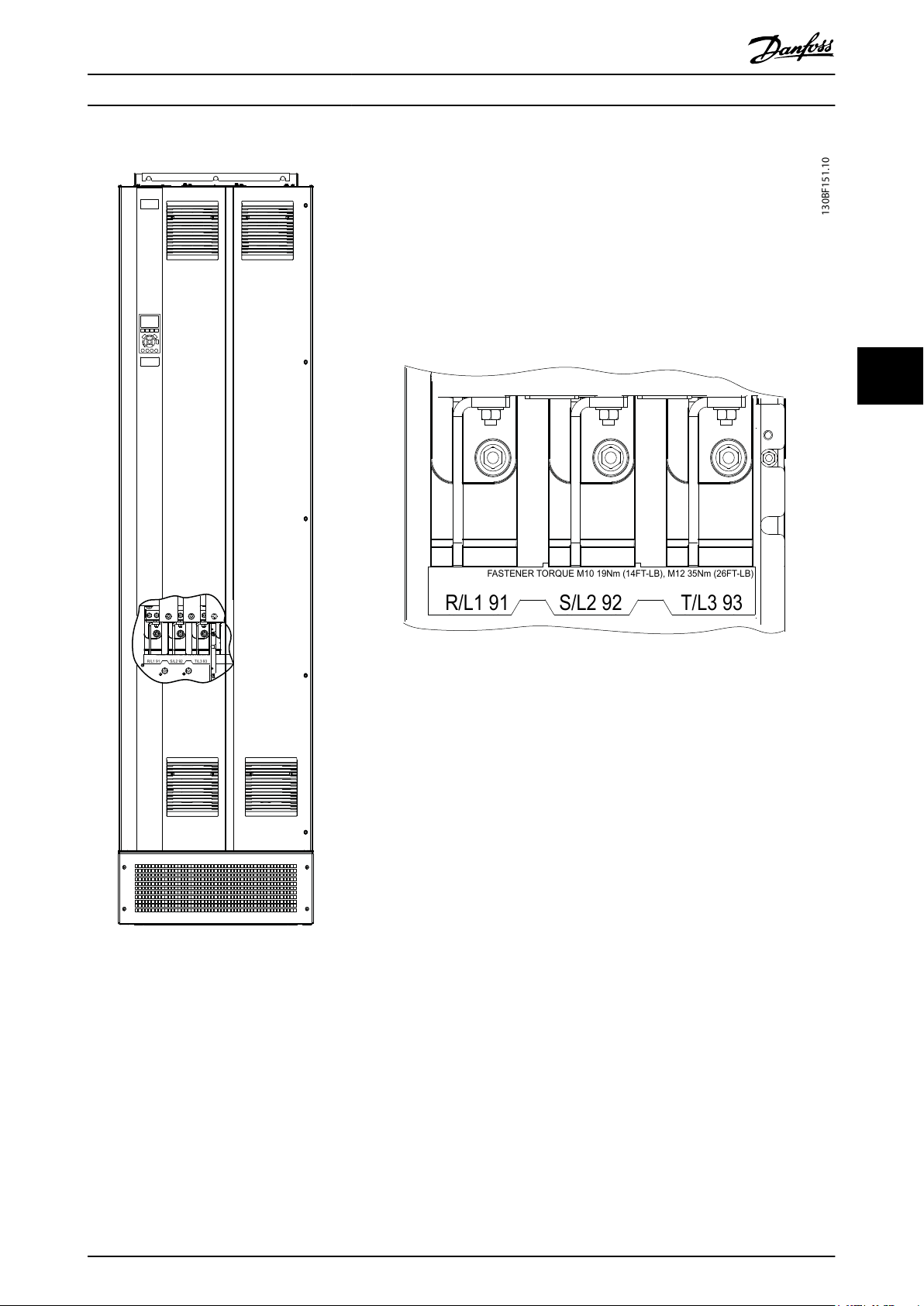
5.5 Connecting the AC Mains
Size the wiring according to the input current of the drive. For maximum wire sizes, see chapter 9.1 Electrical Data.
•
Comply with local and national electrical codes for cable sizes.
•
Procedure
1. Strip a section of the outer cable insulation.
2. Establish mechanical xation and electrical contact between the cable shield and ground by positioning the
stripped wire under the cable clamp.
3. Connect the ground wire to the nearest grounding terminal in accordance with the grounding instructions
provided in chapter 5.6 Connecting to Ground.
55
4. Connect the 3-phase AC input power wiring to terminals R, S, and T (see Illustration 5.4).
5. When supplied from an isolated mains source (IT mains or oating delta) or TT/TN-S mains with a grounded leg
(grounded delta), ensure that parameter 14-50 RFI Filter is set to [0] O to avoid damage to the DC link and to
reduce ground capacity currents.
6. Tighten the terminals in accordance with the information provided in chapter 9.10.1 Fastener Torque Ratings.
26 Danfoss A/S © 01/2017 All rights reserved. MG22A102
Page 29
130BF151.10
T/L3 93
S/L2 92
R/L1 91
FASTENER TORQUE M10 19Nm (14FT-LB), M12 35Nm (26FT-LB)
T/L3 93
S/L2 92
R/L1 91
FASTENER TORQUE M10 19Nm (14FT-LB), M12 35Nm (26FT-LB)
Electrical Installation Operating Guide
5 5
Illustration 5.4 AC mains terminals (E1h shown). For a detailed view of terminals, refer to chapter 5.7 Terminal Dimensions.
MG22A102 Danfoss A/S © 01/2017 All rights reserved. 27
Page 30

Electrical Installation VLT® AQUA Drive FC 202
5.6 Connecting to Ground
WARNING
LEAKAGE CURRENT HAZARD
Leakage currents exceed 3.5 mA. Failure to ground the drive properly can result in death or serious injury.
Ensure the correct grounding of the equipment by a certied electrical installer.
•
For electrical safety
Ground the drive in accordance with applicable standards and directives.
•
Use a dedicated ground wire for input power, motor power, and control wiring.
55
•
Do not ground 1 drive to another in a daisy chain fashion.
•
Keep the ground wire connections as short as possible.
•
Follow motor manufacturer wiring requirements.
•
Minimum cable cross-section: 10 mm2 (6 AWG) (or 2 rated ground wires terminated separately).
•
Tighten the terminals in accordance with the information provided in chapter 9.10.1 Fastener Torque Ratings.
•
For EMC-compliant installation
Establish electrical contact between the cable shield and the drive enclosure by using metal cable glands or by
•
using the clamps provided on the equipment.
Reduce burst transient by using high-strand wire.
•
Do not use pigtails.
•
NOTICE
POTENTIAL EQUALIZATION
There is a risk of burst transient when the ground potential between the drive and the control system is dierent.
Install equalizing cables between the system components. Recommended cable cross-section: 16 mm2 (5 AWG).
28 Danfoss A/S © 01/2017 All rights reserved. MG22A102
Page 31

130BF152.10
U/T1 96 V/T2 97
W/T3 98
T/L3 93S/L2 92R/L1 91
FASTENER TORQUE M10 19Nm (14FT-LB), M12 35Nm (26FT-LB)
FASTENER TORQUE M10 19Nm (14FT-LB), M12 35Nm (26FT-LB)
U/T1 96 V/T2 97
W/T3 98
T/L3 93S/L2 92R/L1 91
FASTENER TORQUE M10 19Nm (14FT-LB), M12 35Nm (26FT-LB)
FASTENER TORQUE M10 19Nm (14FT-LB), M12 35Nm (26FT-LB)
Electrical Installation Operating Guide
5 5
Illustration 5.5 Ground terminals (E1h shown). For a detailed view of terminals, refer to chapter 5.7 Terminal Dimensions.
MG22A102 Danfoss A/S © 01/2017 All rights reserved. 29
Page 32

130BF683.10
6X 613 (24.1)
383 (15.1)
472 (18.6)
423 (16.7)
165 (6.5)
0 (0.0)
101 (4.0)
82 (3.2)
721 (28.4)
0 (0.0)
1
2
3
4
200 (7.9)
515 (20.3)
485 (19.1)
248 (9.8)
241 (9.5)
171 (6.7)
414 (16.3)
361 (14.2)
331 (13.0)
501 (19.7)
497 (19.6)
431 (17.0)
512 (20.2)
5
Electrical Installation VLT® AQUA Drive FC 202
5.7 Terminal Dimensions
5.7.1 E1h Terminal Dimensions
55
1 Mains terminals 3 Motor terminals
2 Brake or regeneration terminals 4 Ground terminals, M10 nut
Illustration 5.6 E1h Terminal Dimensions (Front View)
30 Danfoss A/S © 01/2017 All rights reserved. MG22A102
Page 33

130BF650.10
A
A
649 (25.5)649 (25.5)
0 (0.0)
0 (0.0)
0 (0.0)
164 (6.4)
290 (11.4)
377 (14.8)
0 (0.0)
164 (6.4)
290 (11.4)
18 (0.7)
0 (0.0)
84 (3.3)
42 (1.7)
5X
0 (0.0)
36 (1.4)
44 (1.8)
14 (0.5)
Electrical Installation Operating Guide
5 5
Illustration 5.7 E1h Terminal Dimensions (Side Views)
MG22A102 Danfoss A/S © 01/2017 All rights reserved. 31
Page 34

130BF689.10
721 (28.4)
6X 613 (24.1)
1
515 (20.3)
485 (19.1)
0 (0.0)
200 (7.9)
185 (7.3)
0 (0.0)
101 (4.0)
89 (3.5)
289 (11.4)
281 (11.1)
195 (7.7)
483 (19.0)
409 (16.1)
387 (15.2)
597 (23.5)
579 (22.8)
503 (19.8)
479 (18.9)
568 (22.4)
519 (20.4)
608 (23.9)
2
3
4
Electrical Installation VLT® AQUA Drive FC 202
5.7.2 Mains, Motor, and Ground for E2h
55
1 Mains terminals 3 Motor terminals
2 Brake or regeneration terminals 4 Ground terminals, M10 nut
Illustration 5.8 E2h Terminal Dimensions (Front View)
32 Danfoss A/S © 01/2017 All rights reserved. MG22A102
Page 35

649 (25.5)649 (25.5)
0 (0.0)
0 (0.0)
0 (0.0)
164 (6.4)
290 (11.4)
377 (14.8)
0 (0.0)
164 (6.4)
290 (11.4)
130BF690.10
A
18 (0.7)
0 (0.0)
84 (3.3)
42 (1.7)
5X
0 (0.0)
36 (1.4)
44 (1.8)
14 (0.5)
A
Electrical Installation Operating Guide
5 5
Illustration 5.9 E2h Terminal Dimensions (Side Views)
MG22A102 Danfoss A/S © 01/2017 All rights reserved. 33
Page 36

130BF660.10
336 (13.2)
425 (16.7)
376 (14.8)
465 (18.3)
256 (10.1)
33 (1.3)
6X 148 (5.8)
90 (3.5)
50 (2.0)
0 (0.0)
0 (0.0)
64 (2.5)
35 (1.4)
91 (3.6)
118 (4.6)
194 (7.6)
174 (6.9)
201 (7.9)
284 (11.2)
340 (13.4)
314 (12.3)
367 (14.4)
444 (17.5)
423 (16.7)
450 (17.7)
2
3
4
1
Electrical Installation VLT® AQUA Drive FC 202
5.7.3 Mains, Motor, and Ground for E3h
55
1 Mains terminals 3 Motor terminals
2 Brake or regeneration terminals 4 Ground terminals, M8 and M10 nuts
Illustration 5.10 E3h Terminal Dimensions (Front View)
34 Danfoss A/S © 01/2017 All rights reserved. MG22A102
Page 37

130BF661.10
0 (0.0)
0 (0.0)
160 (6.3)
0 (0.0)
373 (14.7)
287 (11.3)
287 (11.3)
160 (6.3)
0 (0.0)
184
(7.2)
184
(7.2)
A
5X 14 (0.5)
44 (1.8)
0 (0.0)
36 (1.4)
18 (0.7)
0 (0.0)
84 (3.3)
42 (1.7)
A
Electrical Installation Operating Guide
5 5
Illustration 5.11 E3h Mains, Motor, and Ground Terminal Dimensions (Side Views)
MG22A102 Danfoss A/S © 01/2017 All rights reserved. 35
Page 38

130BF663.10
0 (0.0)
234 (9.2)
314 (12.4)
0 (0.0)
176 (6.9)
A
A
8X 14 (0.5)
20 (0.8)
0 (0.0)
35(1.4)
0 (0.0)
15 (0.6)
35 (1.4)
50 (2.0)
75 (3.0)
90 (3.5)
125 (4.9)
140 (5.5)
2X 125 (4.9)
0 (0.0)
Electrical Installation VLT® AQUA Drive FC 202
55
Illustration 5.12 E3h Load Share/Regeneration Terminal Dimensions
36 Danfoss A/S © 01/2017 All rights reserved. MG22A102
Page 39

130BF668.10
6X 148 (5.8)
90 (3.5)
50 (2.0)
0 (0.0)
1
0 (0.0)
64 (2.5)
41 (1.6)
105 (4.1)
137 (5.4)
194 (7.6)
200 (7.9)
233 (9.2)
402 (15.8)
339 (13.4)
410 (16.1)
499 (19.6)
435 (17.1)
531 (20.9)
256 (10.1)
33 (1.3)
2
3
4
540 (21.2)
432 (17.0)
521 (20.5)
472 (18.6)
561 (22.1)
Electrical Installation Operating Guide
5.7.4 Mains, Motor, and Ground for E4h
5 5
1 Mains terminals 3 Motor terminals
2 Brake or regeneration terminals 4 Ground terminals, M8 and M10 nuts
Illustration 5.13 E4h Terminal Dimensions (Front View)
MG22A102 Danfoss A/S © 01/2017 All rights reserved. 37
Page 40

130BF681.10
5X 14 (0.5)
44 (1.8)
0 (0.0)
36 (1.4)
0 (0.0)
373 (14.7)
287 (11.3)
160 (6.3)
0 (0.0)
0 (0.0)
160 (6.3)
0 (0.0)
287 (11.3)
184
(7.2)
184
(7.2)
A
18 (0.7)
0 (0.0)
84 (3.3)
42 (1.7)
Electrical Installation VLT® AQUA Drive FC 202
55
Illustration 5.14 E4h Mains, Motor, and Ground Terminal Dimensions (Side Views)
38 Danfoss A/S © 01/2017 All rights reserved. MG22A102
Page 41

130BF682.10
A
20 (0.8)
0 (0.0)
35(1.4)
0 (0.0)
15 (0.6)
35 (1.4)
50 (2.0)
75 (3.0)
90 (3.5)
125 (4.9)
140 (5.5)
8X 14 (0.5)
2X 125 (4.9)
0 (0.0)
0 (0.0)
234 (9.2)
314 (12.4)
0 (0.0)
219 (8.6)
A
Electrical Installation Operating Guide
5 5
Illustration 5.15 E4h Load Share/Regeneration Terminal Dimensions
MG22A102 Danfoss A/S © 01/2017 All rights reserved. 39
Page 42

130BF715.10
130BF144.10
12 13 18 19 27 29 32 33 20 37
39696861 42 50 53 54 55
130BF145.10
1
2
3
Electrical Installation VLT® AQUA Drive FC 202
5.8 Control Wiring
All terminals to the control cables are inside the drive
below the LCP. To access, either open the door (E1h and
E2h) or remove the front panel (E3h and E4h).
5.8.2 Control Terminal Types
Illustration 5.17 shows the removable drive connectors.
Terminal functions and default settings are summarized in
Table 5.1 – Table 5.3.
5.8.1 Control Cable Routing
Tie down and route all control wires as shown in
Illustration 5.16. Remember to connect the shields in a
proper way to ensure optimum electrical immunity.
55
Fieldbus connection
Connections are made to the relevant options on the
control card. For more detail, see the relevant eldbus
instruction. The cable must be tied down and routed along
with other control wires inside the unit. See
Illustration 5.16.
Isolate control wiring from high-power cables in
•
the drive.
When the drive is connected to a thermistor,
•
ensure that the thermistor control wiring is
shielded and reinforced/double insulated. A 24 V
DC supply voltage is recommended.
Illustration 5.17 Control Terminal Locations
1 Serial communication terminals
Illustration 5.16 Control Card Wiring Path
40 Danfoss A/S © 01/2017 All rights reserved. MG22A102
2 Digital input/output terminals
3 Analog input/output terminals
Illustration 5.18 Terminal Numbers Located on the Connectors
Serial communication terminals
Terminal Parameter Default
setting
61 – – Integrated RC-lter for
Description
cable shield. ONLY for
connecting the shield
in the event of EMC
problems.
Page 43

RELAY 1 RELAY 2
01 02 03 04 05 06
130BF156.10
Electrical Installation Operating Guide
Serial communication terminals
Terminal Parameter Default
setting
68 (+) Parameter
group 8-3* FC
Port Settings
69 (-) Parameter
group 8-3* FC
Port Settings
01, 02, 03 Parameter 5-40
Function Relay
[0]
04, 05, 06 Parameter 5-40
Function Relay
[1]
Table 5.1 Serial Communication Terminal Descriptions
Digital input/output terminals
Terminal Parameter Default
12, 13 – +24 V DC 24 V DC supply
18 Parameter 5-10
Terminal 18
Digital Input
19 Parameter 5-11
Terminal 19
Digital Input
32 Parameter 5-14
Terminal 32
Digital Input
33 Parameter 5-15
Terminal 33
Digital Input
27 Parameter 5-12
Terminal 27
Digital Input
29 Parameter 5-13
Terminal 29
Digital Input
20 – – Common for digital
– RS485 interface. A
–
Relays
[0] No
operation
[0] No
operation
setting
[8] Start Digital inputs.
[10]
Reversing
[0] No
operation
[0] No
operation
[2] Coast
inverse
[14] JOG
Description
switch (BUS TER.) is
provided on the
control card for bus
termination
resistance. See
Illustration 5.22.
Form C relay output.
For AC or DC voltage
and resistive or
inductive loads.
Description
voltage for digital
inputs and external
transducers.
Maximum output
current 200 mA for all
24 V loads.
For digital input or
output. Default
setting is input.
inputs and 0 V
potential for 24 V
supply.
Digital input/output terminals
Terminal Parameter Default
setting
37 – STO When not using the
Table 5.2 Digital Input/Output Terminal Descriptions
Analog input/output terminals
Terminal Parameter Default
setting
39 – – Common for analog
42 Parameter 6-50
Terminal 42
Output
50 – +10 V DC 10 V DC analog
53 Parameter
group 6-1*
Analog Input 1
54 Parameter
group 6-2*
Analog Input 2
55 – – Common for analog
Table 5.3 Analog Input/Output Terminal Descriptions
[0] No
operation
Reference Analog input. For
Feedback
Description
optional STO feature,
a jumper wire is
required between
terminal 12 (or 13)
and terminal 37. This
set-up allows the
drive to operate with
factory default
programming values.
Description
output.
Programmable analog
output. 0–20 mA or
4–20 mA at a
maximum of 500 Ω.
supply voltage for
potentiometer or
thermistor. 15 mA
maximum.
voltage or current.
Switches A53 and
A54 select mA or V.
input.
Relay terminals:
Illustration 5.19 Relay 1 and Relay 2 Terminals
Relay 1 and relay 2. The location of the outputs
•
depends on the drive conguration. See
chapter 3.5 Control Shelf.
Terminals on built-in optional equipment. See the
•
manual provided with the equipment option.
5 5
MG22A102 Danfoss A/S © 01/2017 All rights reserved. 41
Page 44

130BD546.11
2
1
10 mm
[0.4 inches]
12 13 18 19 27 29 32 33
Electrical Installation VLT® AQUA Drive FC 202
5.8.3 Wiring to Control Terminals
Control terminal connectors can be unplugged from the
drive for ease of installation, as shown in Illustration 5.20.
55
Illustration 5.20 Connecting Control Wires
NOTICE
Minimize interference by keeping control wires as short
as possible and separate from high-power cables.
1. Open the contact by inserting a small screwdriver
2. Insert the bare control wire into the contact.
3. Remove the screwdriver to fasten the control wire
4. Ensure that the contact is rmly established and
See chapter 9.1 Electrical Data for control terminal wiring
sizes and chapter 7 Wiring Conguration Examples for
typical control wiring connections.
5.8.4 Enabling Motor Operation
(Terminal 27)
A jumper wire is required between terminal 12 (or 13) and
terminal 27 for the drive to operate when using factory
default programming values.
•
•
•
into the slot above the contact and push the
screwdriver slightly upwards.
into the contact.
not loose. Loose control wiring can be the source
of equipment faults or reduced performance.
Digital input terminal 27 is designed to receive
24 V DC external interlock command.
When no interlock device is used, wire a jumper
between control terminal 12 (recommended) or
13 to terminal 27. This wire provides an internal
24 V signal on terminal 27.
When the status line at the bottom of the LCP
reads AUTO REMOTE COAST, the unit is ready to
operate, but is missing an input signal on
terminal 27.
When factory-installed optional equipment is
•
wired to terminal 27, do not remove that wiring.
NOTICE
The drive cannot operate without a signal on terminal
27, unless terminal 27 is reprogrammed using
parameter 5-12 Terminal 27 Digital Input.
5.8.5 Conguring RS485 Serial
Communication
RS485 is a 2-wire bus interface compatible with multi-drop
network topology, and it contains the following features:
Either Danfoss FC or Modbus RTU communication
•
protocol, which are internal to the drive, can be
used.
Functions can be programmed remotely using
•
the protocol software and RS485 connection or in
parameter group 8-** Communications and
Options.
Selecting a
•
changes various default parameter settings to
match the specications of the protocol, making
more protocol-specic parameters available.
Option cards for the drive are available to provide
•
more communication protocols. See the option
card documentation for installation and operation
instructions.
A switch (BUS TER) is provided on the control
•
card for bus termination resistance. See
Illustration 5.22.
For basic serial communication set-up, perform the
following steps:
1. Connect RS485 serial communication wiring to
terminals (+)68 and (-)69.
1a Use shielded serial communication cable
1b See chapter 5.6 Connecting to Ground for
2. Select the following parameter settings:
2a Protocol type in parameter 8-30 Protocol.
2b Drive address in parameter 8-31 Address.
2c Baud rate in parameter 8-32 Baud Rate.
specic communication protocol
(recommended).
proper grounding.
42 Danfoss A/S © 01/2017 All rights reserved. MG22A102
Page 45

61
68
69
+
130BB489.10
RS485
Electrical Installation Operating Guide
5.8.8 Wiring the Auxiliary Contacts to the
Disconnect
The disconnect is an option that is installed at the factory.
The auxiliary contacts, which are signal accessories used
with the disconnect, are not installed at the factory to
allow more exibility during installation. The contacts snap
into place without the need for tools.
Illustration 5.21 Serial Communication Wiring Diagram
5.8.6 Wiring Safe Torque O (STO)
The Safe Torque O (STO) function is a component in a
safety control system. STO prevents the unit from
generating the voltage required to rotate the motor.
To run STO, more wiring for the drive is required. Refer to
Safe Torque
O Operating Guide for further information.
5.8.7 Wiring the Space Heater
The space heater is an option used to prevent condensation from forming inside the enclosure when the unit is
turned o. It is designed to be eld wired and controlled
by an HVAC management system.
Specications
Nominal voltage: 100–240
•
Wire size: 12–24 AWG
•
Contacts must be installed in
disconnect depending upon their functions. Refer to the
datasheet included in the accessory bag that comes with
the drive.
Specications
Ui/[V]: 690
•
U
/[kV]: 4
imp
•
Pollution degree: 3
•
Ith/[A]: 16
•
Cable size: 1...2x0.75...2.5 mm
•
Maximum fuse: 16 A/gG
•
NEMA: A600, R300, wire size: 18–14 AWG, 1(2)
•
specic locations on the
2
5.8.9 Wiring the Brake Resistor Temperature
Switch
The brake resistor terminal block is located on the power
card and allows for the connection of an external brake
resistor temperature switch. The switch can be congured
as normally closed or normally open. If the input changes,
a signal trips the drive and shows alarm 27, Brake chopper
fault on the LCP display. At the same time, the drive stops
braking and the motor coasts.
1. Locate the brake resistor terminal block (terminals
104–106) on the power card. See Illustration 3.3.
2. Remove the M3 screws that hold the jumper to
the power card.
3. Remove the jumper and wire the brake resistor
temperature switch in 1 of the following congu-
rations:
3a Normally closed. Connect to terminals
104 and 106.
3b Normally open. Connect to terminals
104 and 105.
4. Secure the switch wires with the M3 screws.
Torque to 0.5-0.6 Nm (5 in lb).
5 5
MG22A102 Danfoss A/S © 01/2017 All rights reserved. 43
Page 46

130BF146.10
BUS TER.
OFF-ON
A53 A54
U- I U- I
1
2
N O
1
2
N O
1
2
N O
1
2
N O
Electrical Installation VLT® AQUA Drive FC 202
5.8.10 Selecting Voltage/Current Input
Signal
The analog input terminals 53 and 54 allow setting of
input signal to voltage (0–10 V) or current (0/4–20 mA).
Default parameter setting:
Terminal 53: Speed reference signal in open loop
•
(see parameter 16-61 Terminal 53 Switch Setting).
Terminal 54: Feedback signal in closed loop (see
•
parameter 16-63 Terminal 54 Switch Setting).
55
NOTICE
Disconnect power to the drive before changing switch
positions.
1. Remove the LCP (local control panel).
See chapter 6.3 LCP Menu.
2. Remove any optional equipment covering the
switches.
3. Set switches A53 and A54 to select the signal
type (U = voltage, I = current).
Illustration 5.22 Location of Terminal 53 and 54 Switches
44 Danfoss A/S © 01/2017 All rights reserved. MG22A102
Page 47

Electrical Installation Operating Guide
5.9 Pre-start Check List
Before completing installation of the unit, inspect the entire installation as detailed in Table 5.4. Check and mark the items
when completed.
Inspect for Description
Auxiliary equipment•Look for auxiliary equipment, switches, disconnects, or input fuses/circuit breakers that reside on the input
power side of the drive or output side to the motor. Ensure that they are ready for full-speed operation.
Check function and installation of any sensors used for feedback to the drive.
•
Remove any power factor correction caps on motor.
•
Adjust any power factor correction caps on the mains side and ensure that they are dampened.
•
Cable routing
Control wiring
Cooling clearance
Ambient conditions
Fusing and circuit
breakers
Grounding
Input and output
power wiring
Panel interior
Switches
Vibration
Ensure that motor wiring, brake wiring (if equipped), and control wiring are separated or shielded, or in 3
•
separate metallic conduits for high-frequency interference isolation.
Check for broken or damaged wires and loose connections.
•
Check that control wiring is isolated from high-power wiring for noise immunity.
•
Check the voltage source of the signals, if necessary.
•
The use of shielded cable or twisted pair is recommended. Ensure that the shield is terminated correctly.
•
Measure top clearance for adequate airow for cooling, see chapter 4.5.1 Installation and Cooling
•
Requirements.
Check that requirements for ambient conditions are met. See chapter 9.4 Ambient Conditions.
•
Check for proper fusing or circuit breakers.
•
Check that all fuses are inserted rmly and are in operational condition and that all circuit breakers (if
•
used) are in the open position.
Check for good ground connections that are tight and free of oxidation.
•
Grounding to conduit, or mounting the back panel to a metal surface, is not a suitable grounding.
•
Check for loose connections.
•
Check that motor and mains are in separate conduit or separated shielded cables.
•
Inspect that the unit interior is free of dirt, metal chips, moisture, and corrosion.
•
Verify that all installation tools have been removed from unit interior.
•
For E3h and E4h enclosures, ensure that the unit is mounted on an unpainted, metal surface.
•
Ensure that all switch and disconnect settings are in the proper positions.
•
Check that the unit is mounted solidly, or that shock mounts are used, if necessary.
•
Check for an unusual amount of vibration.
•
☑
5 5
Table 5.4 Pre-start Check List
CAUTION
POTENTIAL HAZARD IN THE EVENT OF INTERNAL FAILURE
If the drive is not properly secured with covers, personal injury can occur.
Before applying power, ensure all safety covers (door and panels) are in place and securely fastened. Refer to
•
chapter 9.10.1 Fastener Torque Ratings.
MG22A102 Danfoss A/S © 01/2017 All rights reserved. 45
Page 48

Commissioning VLT® AQUA Drive FC 202
6 Commissioning
6
6.1 Safety Instructions
See chapter 2 Safety for general safety instructions.
WARNING
HIGH VOLTAGE
Drives contain high voltage when connected to AC mains
input power. Failure to use qualied personnel to install,
start up, and maintain the drive can result in death or
serious injury.
Only qualied personnel must install, start up,
•
and maintain the drive.
Before applying power:
1. Close cover properly.
2. Check that all cable glands are rmly tightened.
3. Ensure that input power to the unit is OFF and
locked out. Do not rely on the drive disconnect
switches for input power isolation.
4. Verify that there is no voltage on input terminals
L1 (91), L2 (92), and L3 (93), phase-to-phase, and
phase-to-ground.
5. Verify that there is no voltage on output
terminals 96 (U), 97 (V), and 98 (W), phase-tophase, and phase-to-ground.
6. Conrm continuity of the motor by measuring
ohm values on U–V (96–97), V–W (97–98), and W–
U (98–96).
7. Check for proper grounding of the drive and the
motor.
8. Inspect the drive for loose connections on the
terminals.
9. Conrm that the supply voltage matches the
voltage of the drive and the motor.
Applying Power
6.2
WARNING
UNINTENDED START
When the drive is connected to AC mains, DC supply, or
load sharing, the motor can start at any time.
Unintended start during programming, service, or repair
work can result in death, serious injury, or property
damage. The motor can start with an external switch, a
eldbus command, an input reference signal from the
LCP or LOP, via remote operation using MCT 10 Set-up
Software, or after a cleared fault condition.
To prevent unintended motor start:
Press [O/Reset] on the LCP before
•
programming parameters.
Disconnect the drive from the mains.
•
Completely wire and assemble the drive, motor,
•
and any driven equipment before connecting
the drive to the AC mains, DC supply, or load
sharing.
1. Conrm that the input voltage between phases is
balanced within 3%. If not, correct input voltage
imbalance before proceeding. Repeat this
procedure after the voltage correction.
2. Ensure that optional equipment wiring, if present,
matches the installation application.
3. Ensure that all operator devices are in the OFF
position.
4. Close all panel doors and securely fasten all
covers.
5. Apply power to the unit. DO NOT start the drive
now. For units with a disconnect switch, turn to
the ON position to apply power to the drive.
NOTICE
If the status line at the bottom of the LCP reads AUTO
REMOTE COASTING or alarm 60, External Interlock is
shown, this status indicates that the unit is ready to
operate but is missing an input signal on terminal 27.
See chapter 5.8.4 Enabling Motor Operation (Terminal 27)
for details.
46 Danfoss A/S © 01/2017 All rights reserved. MG22A102
Page 49

130BF242.10
01 My Personal Menu
02 Quick Setup
05 Changes Made
06 Loggings
0.0% 0.00
Quick Menus
1(1)
07 Water and Pumps
03 Function Setups
04 Smart Start
130BP066.12
Keypad Set-Up
Parameter Data Set
Parameter Data Check
Drive Information
18.4% 5.22A
Main Menu
1(1)
07 Motor Setup
Commissioning Operating Guide
6.3 LCP Menu
For more detailed instructions regarding the menus or
parameters, refer to the programming guide.
6.3.1.1 Quick Menu Mode
The LCP provides access to parameters via the Quick
Menus. To list the quick menu options, press [Quick
Menus].
Illustration 6.1 Quick Menu View
6.3.1.6 Q5 Changes Made
Select Q5 Changes Made for information about:
The 10 most recent changes.
•
Changes made from default setting.
•
6.3.1.7 Q6 Loggings
Use Q6 Loggings for fault nding. To get information about
the display line readout, select Loggings. The information is
shown as graphs. Only parameters selected in
parameter 0-20 Display Line 1.1 Small through
parameter 0-24 Display Line 3 Large can be viewed. It is
possible to store up to 120 samples in the memory for
later reference.
Q6 Loggings
Parameter 0-20 Display Line 1.1 Small Reference [Unit]
Parameter 0-21 Display Line 1.2 Small Analog Input 53 [V]
Parameter 0-22 Display Line 1.3 Small Motor current [A]
Parameter 0-23 Display Line 2 Large Frequency [Hz]
Parameter 0-24 Display Line 3 Large Feedback [Unit]
Table 6.1 Logging Parameter Examples
6
6
6.3.1.2 Q1 My Personal Menu
The Personal Menu is used to determine what is shown in
the display area. Refer to chapter 3.6 Local Control Panel
(LCP). This menu can also show up to 50 pre-programmed
parameters. These 50 parameters are manually entered
using parameter 0-25 My Personal Menu.
6.3.1.3 Q2 Quick Setup
The parameters found in the Q2 Quick Setup contain basic
system and motor data that are always necessary for
conguring the drive. See chapter 6.4.2 Entering System
Information for the set-up procedures.
6.3.1.4 Q3 Function Setups
The parameters found in the Q3 Function Setups contain
data for fan, compressor, and pump functions. This menu
also includes parameters for LCP display, digital preset
speeds, scaling of analog references, closed-loop single
zone, and multizone applications.
6.3.1.8 Q7 Water and Pumps
The parameters found in the Q7 Water and Pumps contain
basic data that is necessary for conguring water pump
applications.
6.3.1.9 Main Menu Mode
The LCP provides access to the Main Menu mode. Select
the Main Menu mode by pressing the [Main Menu] key.
The resulting readout appears on the LCP display.
Illustration 6.2 Main Menu View
6.3.1.5 Q4 Smart Start
The Q4 Smart Start function prompts the user for questions
based on the previous answer which, in turn, automatically
congures the motor and selected pump/fan/conveyor
application.
MG22A102 Danfoss A/S © 01/2017 All rights reserved. 47
Lines 2 through 5 on the display show a list of parameter
groups that can be selected via the [▲] and [▼] keys.
All parameters can be changed in the main menu. Option
cards added to the unit enable extra parameters associated
with the option device.
Page 50

130BT112.12
Q1 My Personal Menu
Q2 Quick Setup
Q3 Function Setups
Q5 Changes Made
69.3% 5.20A 1(1)
Quick Menus
130BF725.10
Q3
Q3-1 General Settings
Q3-2 Open Loop Settings
Q3-3 Closed Loop Settings
Q3-4 Application Settings
28.4% 2.05A 1(1)
Function Setups
Commissioning VLT® AQUA Drive FC 202
6
6.4 Programming the Drive
For detailed information on the key functions on the local
control panel (LCP), see chapter 3.6 Local Control Panel
(LCP). For information on parameter settings, see the
programming guide.
Parameter overview
Parameter settings control the operation of the drive, and
are accessed via the LCP. These settings are assigned a
default value at the factory, but can be
unique application. Each parameter has a name and
number that remain the same regardless of the
programming mode.
In the Main Menu mode, the parameters are divided into
groups. The rst digit of the parameter number (from the
left) indicates the parameter group number. The parameter
group is then broken down into sub groups, if necessary.
For example:
0-** Operation/Display Parameter group
0-0* Basic Settings Parameter sub group
Parameter 0-01 Language Parameter
Parameter 0-02 Motor Speed Unit Parameter
Parameter 0-03 Regional Settings Parameter
Table 6.2 Example of Parameter Group Hierarchy
congured for their
6.4.1 Programming Example for an Openloop Application
This procedure, which is used to congure a typical openloop application, programs the drive to receive a 0–10 V
DC analog control signal on input terminal 53. The drive
responds by providing 20–50 Hz output to the motor
proportional to the input signal (0–10 V DC=20–50 Hz).
Press [Quick Menu] and complete the following steps:
1. Select Q3 Function Setups and press [OK].
2. Select Parameter Data Set and press [OK].
Illustration 6.3 Q3 Function Setups
Moving around parameters
Navigate through the parameters using the following LCP
keys:
Press [▲] [▼] to scroll up or down.
•
Press [◄] [►] to shift a space to the left or right of
•
a decimal point while editing a decimal
parameter value.
Press [OK] to accept the change.
•
Press [Cancel] to disregard the change and exit
•
edit mode.
Press [Back] twice to show the status view.
•
Press [Main Menu] once to go back to the main
•
menu.
3. Select Q3-2 Open Loop Settings and press [OK].
Illustration 6.4 Q3-2 Open Loop Settings
48 Danfoss A/S © 01/2017 All rights reserved. MG22A102
Page 51

130BF726.10
Q3-2
Q3-20 Digital Reference
Q3-21 Analog Reference
14.7% 0.00A 1(1)
Open Loop Settings
130BF727.10
Q3-21
3-02 Minimum Reference
0.000 Hz
14.7% 0.00A 1(1)
Analog Reference
130BF728.10
Q3-21
3-03 Maximum Reference
50.000 Hz
14.7% 0.00A 1(1)
Analog Reference
130BF729.10
Q3-21
6-10 Terminal 53 Low
Voltage
0.00 V
14.7% 0.00A 1(1)
Analog Reference
130BF730.10
Q3-21
6-11 Terminal 53 High
Voltage
10.00 V
14.7% 0.00A 1(1)
Analog Reference
130BF731.10
Q3-21
14.7 % 0.00 A 1(1)
Analog Reference
6 - 14 Terminal 53 Low
Ref./Feedb. Value
000020.000
Commissioning Operating Guide
4. Select Q3-21 Analog Reference and press [OK].
Illustration 6.5 Q3-21 Analog Reference
5. Select parameter 3-02 Minimum Reference.
Set the minimum internal drive reference to 0 Hz
and press [OK].
7. Select parameter 6-10 Terminal 53 Low Voltage.
Set the minimum external voltage reference on
terminal 53 at 0 V and press [OK].
Illustration 6.8 Parameter 6-10 Terminal 53 Low Voltage
8. Select parameter 6-11 Terminal 53 High Voltage.
Set maximum external voltage reference on
terminal 53 at 10 V and press [OK].
6
6
Illustration 6.6 Parameter 3-02 Minimum Reference
6. Select parameter 3-03 Maximum Reference.
Set the maximum internal drive reference to
60 Hz and press [OK].
Illustration 6.7 Parameter 3-03 Maximum Reference
MG22A102 Danfoss A/S © 01/2017 All rights reserved. 49
Illustration 6.9 Parameter 6-11 Terminal 53 High Voltage
9. Select parameter 6-14 Terminal 53 Low Ref./Feedb.
Value. Set minimum speed reference on terminal
53 at 20 Hz and press [OK].
Illustration 6.10 Parameter 6-14 Terminal 53 Low Ref./Feedb.
Value
Page 52

130BF732.10
Q3-21
14.7 % 0.00 A 1(1)
Analog Reference
6 - 15 Terminal 53 High
Ref./Feedb. Value
50.000
53
55
6-1*
+
A53
U - I
130BB482.10
0-10V
Commissioning VLT® AQUA Drive FC 202
6
10. Select parameter 6-15 Terminal 53 High Ref./Feedb.
Value. Set maximum speed reference on terminal
53 at 50 Hz and press [OK].
Illustration 6.11 Parameter 6-15 Terminal 53 High Ref./Feedb.
Value
With an external device providing a 0–10 V control signal
connected to drive terminal 53, the system is now ready
for operation.
NOTICE
In Illustration 6.11, the scroll bar on the right of the
display is at the bottom. This position indicates the
procedure is complete.
Illustration 6.12 shows the wiring connections used to
enable the external device set up.
6.4.2 Entering System Information
NOTICE
SOFTWARE DOWNLOAD
For commissioning via PC, install MCT 10 Set-up
Software. The software is available for download (basic
version) or for ordering (advanced version, code number
130B1000). For more information and downloads, see
www.drives.danfoss.com/services/pc-tools.
The following steps are used to enter basic system
information into the drive. Recommended parameter
settings are intended for start-up and checkout purposes.
Application settings vary.
NOTICE
Although these steps assume that an asynchronous
motor is used, a permanent magnet motor can be used.
For more information on specic motor types, see the
product-specic programming guide.
1. Press [Main Menu] on the LCP.
2. Select 0-** Operation/Display and press [OK].
3. Select 0-0* Basic Settings and press [OK].
4. Select parameter 0-03 Regional Settings and
press [OK].
5. Select [0] International or [1] North America as
appropriate and press [OK]. (This action changes
the default settings for some basic parameters).
6. Press [Quick Menus] on the LCP and then select
02 Quick Setup.
7. Change the following parameters settings listed
in Table 6.3 if necessary. The motor data is found
on the motor nameplate.
Illustration 6.12 Wiring Example for External Device Providing
0–10 V Control Signal
50 Danfoss A/S © 01/2017 All rights reserved. MG22A102
Parameter Default setting
Parameter 0-01 Language English
Parameter 1-20 Motor Power [kW ] 4.00 kW
Parameter 1-22 Motor Voltage 400 V
Parameter 1-23 Motor Frequency 50 Hz
Parameter 1-24 Motor Current 9.00 A
Parameter 1-25 Motor Nominal Speed 1420 RPM
Parameter 5-12 Terminal 27 Digital Input Coast inverse
Parameter 3-02 Minimum Reference 0.000 RPM
Parameter 3-03 Maximum Reference 1500.000 RPM
Parameter 3-41 Ramp 1 Ramp Up Time 3.00 s
Parameter 3-42 Ramp 1 Ramp Down Time 3.00 s
Parameter 3-13 Reference Site Linked to Hand/
Auto
Parameter 1-29 Automatic Motor Adaptation
(AMA)
Table 6.3 Quick Setup Settings
O
Page 53

Commissioning Operating Guide
NOTICE
MISSING INPUT SIGNAL
When the LCP shows AUTO REMOTE COASTING or alarm
60, External Interlock, the unit is ready to operate but is
missing an input signal. See chapter 5.8.4 Enabling Motor
Operation (Terminal 27) for details.
6.4.3 Conguring Automatic Energy
Optimization
Automatic energy optimization (AEO) is a procedure that
minimizes voltage to the motor, reducing energy
consumption, heat, and noise.
1. Press [Main Menu].
2. Select 1-** Load and Motor and press [OK].
3. Select 1-0* General Settings and press [OK].
4. Select parameter 1-03 Torque Characteristics and
press [OK].
5. Select either [2] Auto Energy Optim CT or [3] Auto
Energy Optim VT and press [OK].
6.4.4 Conguring Automatic Motor
Adaptation
Automatic motor adaptation is a procedure that optimizes
compatibility between the drive and the motor.
The drive builds a mathematical model of the motor for
regulating output motor current. The procedure also tests
the input phase balance of electrical power. It compares
the motor characteristics with the data entered in
parameters 1-20 to 1-25.
NOTICE
If warnings or alarms occur, see chapter 8.5 List of
Warnings and Alarms. Some motors are unable to run the
complete version of the test. In that case, or if an output
lter is connected to the motor, select [2] Enable reduced
AMA.
Run this procedure on a cold motor for best results.
1. Press [Main Menu].
2. Select 1-** Load and Motor and press [OK].
3. Select 1-2* Motor Data and press [OK].
4. Select parameter 1-29 Automatic Motor Adaptation
(AMA) and press [OK].
5. Select [1] Enable complete AMA and press [OK].
6. Press [Hand On] and then [OK].
The test runs automatically and indicates when it
is complete.
Testing Before System Start-up
6.5
WARNING
MOTOR START
Failure to ensure that the motor, system, and any
attached equipment are ready for start can result in
personal injury or equipment damage. Before start,
Ensure that equipment is safe to operate under
•
any condition.
Ensure that the motor, system, and any
•
attached equipment are ready for start.
6.5.1 Motor Rotation
NOTICE
If the motor runs in the wrong direction, it can damage
equipment. Before running the unit, check the motor
rotation by briey running the motor. The motor runs
briey at either 5 Hz or the minimum frequency set in
parameter 4-12 Motor Speed Low Limit [Hz].
1. Press [Hand On].
2. Move the left cursor to the left of the decimal
point by using the left arrow key, and enter an
RPM that slowly rotates the motor.
3. Press [OK].
4. If the motor rotation is wrong, set
parameter 1-06 Clockwise Direction to [1] Inverse.
6.5.2 Encoder Rotation
If encoder feedback is used, perform the following steps:
1. Select [0] Open Loop in parameter 1-00 Congu-
ration Mode.
2. Select [1] 24 V encoder in parameter 7-00 Speed
PID Feedback Source.
3. Press [Hand On].
4.
Press [►] for positive speed reference
(parameter 1-06 Clockwise Direction at [0] Normal).
5. In parameter 16-57 Feedback [RPM], check that the
feedback is positive.
For more information on the encoder option, refer to the
option manual.
6
6
MG22A102 Danfoss A/S © 01/2017 All rights reserved. 51
Page 54

Commissioning VLT® AQUA Drive FC 202
6
NOTICE
NEGATIVE FEEDBACK
If the feedback is negative, the encoder connection is
wrong. Use either parameter 5-71 Term 32/33 Encoder
Direction or parameter 17-60 Feedback Direction to
inverse the direction, or reverse the encoder cables.
Parameter 17-60 Feedback Direction is only available with
the VLT® Encoder Input MCB 102 option.
6.6 System Start-up
WARNING
MOTOR START
Failure to ensure that the motor, system, and any
attached equipment are ready for start can result in
personal injury or equipment damage. Before start,
Ensure that equipment is safe to operate under
•
any condition.
Ensure that the motor, system, and any
•
attached equipment are ready for start.
The procedure in this section requires user-wiring and
application programming to be completed. The following
procedure is recommended after application set-up is
completed.
1. Press [Auto On].
2. Apply an external run command.
Examples of external run commands are a switch,
button, or programmable logic controller (PLC).
3. Adjust the speed reference throughout the speed
range.
4. Ensure that the system is working as intended by
checking sound and vibration level of the motor.
5. Remove the external run command.
If warnings or alarms occur, see chapter 8.5 List of Warnings
and Alarms.
Parameter Settings
6.7
NOTICE
REGIONAL SETTINGS
Some parameters have dierent default settings for
international or North America. For a list of the dierent
default values, see chapter 10.2 International/North
American Default Parameter Settings.
Parameter settings are stored internally in the drive,
allowing the following advantages:
Parameter settings can be uploaded into the LCP
•
memory and stored as a back-up.
Multiple units can be programmed quickly by
•
connecting the LCP to the unit and downloading
the stored parameter settings.
Settings that are stored in the LCP are not
•
changed when restoring factory default settings.
Changes made to default settings as well as any
•
programming entered into parameters are stored
and available for viewing in the quick menu. See
chapter 6.3 LCP Menu.
6.7.1 Uploading and Downloading
Parameter Settings
The drive operates using parameters stored on the control
card, which is located within the drive. The upload and
download functions move the parameters between the
control card and the LCP.
1. Press
2. Go to parameter 0-50 LCP Copy and press [OK].
3. Select 1 of the following:
4. Press [OK]. A progress bar shows the uploading or
5. Press [Hand On] or [Auto On].
[O].
3a To upload data from the control card to
the LCP, select [1] All to LCP.
3b To download data from the LCP to the
control card, select [2] All from LCP.
downloading process.
6.7.2 Restoring Factory Default Settings
NOTICE
LOSS OF DATA
Loss of programming, motor data, localization, and
monitoring records occurs when restoring default
settings. To create a back-up, upload data to the LCP
before initialization. Refer to chapter 6.7.1 Uploading and
Downloading Parameter Settings.
Restore the default parameter settings by initializing the
unit. Initialization is carried out through
parameter 14-22 Operation Mode or manually.
Establishing the correct programming for applications
requires setting several parameter functions. Details for
parameters are provided in the programming guide.
52 Danfoss A/S © 01/2017 All rights reserved. MG22A102
Page 55

Commissioning Operating Guide
Parameter 14-22 Operation Mode does not reset settings
such as the following:
Running hours
•
Serial communication options
•
Personal menu settings
•
Fault log, alarm log, and other monitoring
•
functions
Recommended initialization
1. Press [Main Menu] twice to access parameters.
2. Go to parameter 14-22 Operation Mode and
press [OK].
3. Scroll to Initialization and press [OK].
4. Remove power to the unit and wait for the
display to turn o.
5. Apply power to the unit. Default parameter
settings are restored during start-up. Start-up
takes slightly longer than normal.
6. After alarm 80, Drive initialized to default value
appears, press [Reset].
Manual initialization
Manual initialization resets all factory settings except for
the following:
Parameter 15-00 Operating hours
•
Parameter 15-03 Power Up's
•
Parameter 15-04 Over Temp's
•
Parameter 15-05 Over Volt's
•
To perform manual initialization:
1. Remove power to the unit and wait for the
display to turn o.
2. Press and hold [Status], [Main Menu], and [OK]
simultaneously while applying power to the unit
(approximately 5 s or until an audible click
sounds and the fan starts). Start-up takes slightly
longer than normal.
6
6
MG22A102 Danfoss A/S © 01/2017 All rights reserved. 53
Page 56

FC
+24 V
+24 V
D IN
D IN
D IN
COM
D IN
D IN
D IN
D IN
+10
V
A IN
A IN
COM
A OUT
COM
12
13
18
19
20
27
29
32
33
37
50
53
54
55
42
39
A53
U - I
-10 - +10V
+
-
130BB926.10
130BB927.10
FC
+24 V
+24 V
D IN
D IN
D IN
COM
D IN
D IN
D IN
D IN
+10
V
A IN
A IN
COM
A OUT
COM
12
13
18
19
20
27
29
32
33
37
50
53
54
55
42
39
A53
U - I
4 - 20mA
+
-
FC
+24 V
+24 V
D IN
D IN
D IN
COM
D IN
D IN
D IN
D IN
+10
V
A IN
A IN
COM
A OUT
COM
12
13
18
19
20
27
29
32
33
37
50
53
54
55
42
39
A53
U - I
≈ 5kΩ
130BB683.10
Wiring Conguration Exampl... VLT® AQUA Drive FC 202
7 Wiring Conguration Examples
The examples in this section are intended as a quick
reference for common applications.
Parameter settings are the regional default values
•
unless otherwise indicated (selected in
parameter 0-03 Regional Settings).
Parameters associated with the terminals and
•
their settings are shown next to the drawings.
Parameters
Function Setting
Parameter 6-12 Terminal
53 Low Current
Parameter 6-13 Terminal
53 High Current
Parameter 6-14 Terminal
53 Low Ref./Feedb.
4 mA*
20 mA*
0 Hz
Value
Required switch settings for analog terminals A53
•
or A54 are also shown.
NOTICE
When not using the optional STO feature, a jumper wire
is required between terminal 12 (or 13) and terminal 37
77
for the drive to operate with factory default
programming values.
Parameter 6-15 Terminal
50 Hz
53 High Ref./Feedb.
Value
* = Default value
Notes/comments:
Assumptions are 4 mA input =
0 Hz speed and 20 mA input =
50 Hz speed.
7.1 Wiring for Open-loop Speed Control
Parameters
Function Setting
Parameter 6-10 Termi
nal 53 Low Voltage
Parameter 6-11 Termi
nal 53 High Voltage
Parameter 6-14 Termi
nal 53 Low Ref./
Feedb. Value
Parameter 6-15 Termi
nal 53 High Ref./
Feedb. Value
* = Default value
Notes/comments:
Assumptions are 0 V DC input
= 0 Hz speed and 10 V DC
input = 50 Hz speed.
Table 7.1 Analog Speed Reference (Voltage)
0.07 V*
10 V*
0 Hz
50 Hz
Table 7.2 Analog Speed Reference (Current)
Parameters
Function Setting
Parameter 6-12 Terminal
53 Low Current
Parameter 6-13 Terminal
53 High Current
Parameter 6-14 Terminal
53 Low Ref./Feedb.
Value
Parameter 6-15 Terminal
53 High Ref./Feedb.
Value
* = Default value
Notes/comments:
Assumptions are 0 V DC input
= 0 RPM speed and 10 V DC
input = 1500 RPM speed.
Table 7.3 Speed Reference (Using a Manual Potentiometer)
4 mA*
20 mA*
0 Hz
50 Hz
54 Danfoss A/S © 01/2017 All rights reserved. MG22A102
Page 57

FC
+24 V
+24 V
D IN
D IN
D IN
COM
D IN
D IN
D IN
D IN
+10 V
A IN
A IN
COM
A OUT
COM
12
13
18
19
20
27
29
32
33
37
50
53
54
55
42
39
130BB804.11
130BB840.12
Speed
Reference
Start (18)
Freeze ref (27)
Speed up (29)
Speed down (32)
FC
+24 V
+24 V
D IN
D IN
D IN
COM
D IN
D IN
D IN
D IN
+10
A IN
A IN
COM
A OUT
COM
12
13
18
19
20
27
29
32
33
37
50
53
54
55
42
39
130BB802.10
130BB805.12
Speed
Start/Stop (18)
Wiring Conguration Exampl... Operating Guide
Parameters
Function Setting
Parameter 5-10 Termin
al 18 Digital Input
Parameter 5-12 Termin
al 27 Digital Input
Parameter 5-13 Termin
al 29 Digital Input
Parameter 5-14 Termin
al 32 Digital Input
* = Default value
Notes/comments:
[8] Start*
[19]
Freeze
Referenc
e
[21]
Speed
Up
[22]
Speed
Down
7.2 Wiring for Start/Stop
Parameters
Function Setting
Parameter 5-10
Terminal 18
Digital Input
Parameter 5-12
Terminal 27
Digital Input
Parameter 5-19
Terminal 37
Digital Input
* = Default value
Notes/comments:
If parameter 5-12 Terminal 27
Digital Input is set to [0] No
operation, a jumper wire to
terminal 27 is not needed.
Table 7.5 Start/Stop Command with Safe Torque O Option
[8] Start*
[0] No
operation
[1] Safe Stop
Alarm
7 7
Table 7.4 Speed Up/Speed Down
Illustration 7.2 Start/Stop Command with Safe Torque O
Illustration 7.1 Speed Up/Speed Down
MG22A102 Danfoss A/S © 01/2017 All rights reserved. 55
Page 58

FC
+24 V
+24 V
D IN
D IN
D IN
COM
D IN
D IN
D IN
D IN
+10 V
A IN
A IN
COM
A OUT
COM
12
13
18
19
20
27
29
32
33
37
50
53
54
55
42
39
130BB803.10
Speed
130BB806.10
Latched Start (18)
Stop Inverse (27)
FC
+24 V
+24 V
D IN
D IN
D IN
COM
D IN
D IN
D IN
+10 V
A IN
A IN
COM
A OUT
COM
12
13
18
19
20
27
29
32
33
50
53
54
55
42
39
130BB934.11
FC
+24 V
+24 V
D IN
D IN
D IN
COM
D IN
D IN
D IN
D IN
+10
V
A IN
A IN
COM
A OUT
COM
12
13
18
19
20
27
29
32
33
37
50
53
54
55
42
39
130BB928.11
Wiring Conguration Exampl... VLT® AQUA Drive FC 202
Parameters
Function Setting
Parameter 5-1
[9] Latched
0 Terminal 18
Digital Input
Parameter 5-1
2 Terminal 27
Digital Input
* = Default value
Notes/comments:
Start
[6] Stop
Inverse
Parameters
Function Setting
Parameter 5-10
Terminal 18
Digital Input
Parameter 5-11
Terminal 19
Reversing*
Digital Input
Parameter 5-12
Terminal 27
[8] Start
[10]
[0] No
operation
Digital Input
Parameter 5-14
Terminal 32
[16] Preset
ref bit 0
Digital Input
Parameter 5-15
Terminal 33
[17] Preset
ref bit 1
Digital Input
Parameter 3-10
77
Preset
Reference
Preset ref. 0
Preset ref. 1
Preset ref. 2
Preset ref. 3
25%
50%
75%
100%
* = Default value
Table 7.6 Pulse Start/Stop
Notes/comments:
Table 7.7 Start/Stop with Reversing and 4 Preset Speeds
Wiring for External Alarm Reset
7.3
Parameters
Function Setting
Parameter 5-11 T
[1] Reset
erminal 19
Digital Input
* = Default value
Notes/comments:
Illustration 7.3 Latched Start/Stop Inverse
Table 7.8 External Alarm Reset
56 Danfoss A/S © 01/2017 All rights reserved. MG22A102
Page 59

130BB686.12
VLT
+24 V
+24 V
D IN
D IN
D IN
COM
D IN
D IN
D IN
+10 V
A IN
A IN
COM
A OUT
COM
12
13
18
19
20
27
29
32
33
50
53
54
55
42
39
A53
U - I
D IN
37
FC
+24 V
+24 V
D IN
D IN
D IN
COM
D IN
D IN
D IN
D IN
+10
V
A IN
A IN
COM
A OUT
COM
12
13
18
19
20
27
29
32
33
37
50
53
54
55
42
39
130BD667.11
Wiring Conguration Exampl... Operating Guide
7.4 Wiring for a Motor Thermistor
WARNING
THERMISTOR INSULATION
Risk of personal injury or equipment damage.
To meet PELV insulation requirements, use only
•
thermistors with reinforced or double
insulation.
Parameters
Function Setting
Parameter 1-90
Motor Thermal
Protection
Parameter 1-93
Thermistor
Source
* = Default value
Notes/comments:
If only a warning is desired, set
parameter 1-90 Motor Thermal
Protection to [1] Thermistor
warning.
[2] Thermistor
trip
[1] Analog
input 53
Wiring for Regeneration
7.5
Parameters
Function Setting
Parameter 1-90
100%*
Motor Thermal
Protection
* = Default value
Notes/comments:
To disable regeneration,
decrease parameter 1-90 Motor
Thermal Protection to 0%. If the
application uses motor brake
power and regeneration is not
enabled, the unit trips.
7 7
Table 7.9 Motor Thermistor
Table 7.10 Regeneration
MG22A102 Danfoss A/S © 01/2017 All rights reserved. 57
Page 60

130BF210.10
Maintenance, Diagnostics, a... VLT® AQUA Drive FC 202
8 Maintenance, Diagnostics, and Troubleshooting
8.1 Maintenance and Service
This chapter includes:
Maintenance and service guidelines.
•
Status messages.
•
Warnings and alarms.
•
Basic troubleshooting.
•
Under normal operating conditions and load proles, the
drive is maintenance-free throughout its designed lifetime.
To prevent breakdown, danger, and damage, examine the
drive at regular intervals depending on the operating
conditions. Replace worn or damaged parts with original
spare parts or standard parts. For service and support, refer
to www.danfoss.com/contact/sales_and_services/.
8.2.1 Removing the Heat Sink Access Panel
WARNING
88
UNINTENDED START
When the drive is connected to AC mains, DC supply, or
load sharing, the motor can start at any time.
Unintended start during programming, service, or repair
work can result in death, serious injury, or property
damage. The motor can start with an external switch, a
eldbus command, an input reference signal from the
LCP or LOP, via remote operation using MCT 10 Set-up
Software, or after a cleared fault condition.
To prevent unintended motor start:
Press [O/Reset] on the LCP before
•
programming parameters.
Disconnect the drive from the mains.
•
Completely wire and assemble the drive, motor,
•
and any driven equipment before connecting
the drive to AC mains, DC supply, or load
sharing.
8.2 Heat Sink Access Panel
The drive can be ordered with an optional access panel in
the back of the unit. This access panel provides access to
the heat sink and allows the heat sink to be cleaned of any
dust buildup.
Illustration 8.1 Heat Sink Access Panel Removed from the Rear
of the Drive
1. Remove power from the drive and wait 40
minutes for the capacitors to discharge
completely. Refer to chapter 2 Safety.
2. Position the drive so that the back of the drive is
fully accessible.
3. Remove the 8 M5 fasteners securing the access
panel to the back of the enclosure using a 3 mm
hex bit.
4. Inspect the leading edge of the heat sink for
damage or debris.
5. Remove material or debris with a vacuum.
6. Reinstall the panel and secure it to the back of
the enclosure with the 8 fasteners. Tighten the
fasteners according to chapter 9.10.1 Fastener
Torque Ratings.
58 Danfoss A/S © 01/2017 All rights reserved. MG22A102
Page 61

Status
799RPM 7.83A 36.4kW
0.000
53.2%
1(1)
Auto
Hand
O
Remote
Local
Ramping
Stop
Running
Jogging
.
.
.
Stand-by
130BB037.11
1
2
3
Maintenance, Diagnostics, a... Operating Guide
NOTICE
DAMAGE TO HEAT SINK
Using fasteners that are longer than those originally
supplied with the heat sink panel will damage the heat
sink cooling ns.
8.3 Status Messages
When the drive is in status mode, status messages
automatically appear in the bottom line of the LCP display.
Refer to Illustration 8.2. Status messages are dened in
Table 8.1 – Table 8.3.
1 Where the stop/start command originates. Refer to Table 8.1.
2 Where the speed control originates. Refer to Table 8.2.
3 Provides the drive status. Refer to Table 8.3.
Illustration 8.2 Status Display
NOTICE
In auto/remote mode, the drive requires external
commands to execute functions.
Table 8.1 to Table 8.3 dene the meaning of the shown
status messages.
O The drive does not react to any control signal
until [Auto On] or [Hand On] is pressed.
Auto The start/stop commands are sent via the
control terminals and/or the serial communi-
cation.
Hand The navigation keys on the LCP can be used
to control the drive. Stop commands, reset,
Table 8.1 Operating Mode
reversing, DC brake, and other signals applied
to the control terminals override local control.
Remote The speed reference is given from
external signals.
•
serial communication.
•
internal preset references.
•
Local The drive uses reference values from the LCP.
Table 8.2 Reference Site
AC brake AC brake was selected in parameter 2-10 Brake
Function. The AC brake overmagnetizes the
motor to achieve a controlled slow down.
AMA nish OK Automatic motor adaptation (AMA) was
carried out successfully.
AMA ready AMA is ready to start. To start, press [Hand
On].
AMA running AMA process is in progress.
Braking The brake chopper is in operation. The brake
resistor absorbs the generative energy.
Braking max. The brake chopper is in operation. The power
limit for the brake resistor dened in
parameter 2-12 Brake Power Limit (kW) has
been reached.
Coast
Ctrl. ramp-down [1] Ctrl. ramp-down was selected in
Current high The drive output current is above the limit set
Current low The drive output current is below the limit set
DC hold DC hold is selected in parameter 1-80 Function
[2] Coast inverse was selected as a function
•
for a digital input (parameter group 5-1*
Digital Inputs). The corresponding terminal
is not connected.
Coast activated by serial communication.
•
parameter 14-10 Mains Failure.
The mains voltage is below the value set
•
in parameter 14-11 Mains Voltage at Mains
Fault at mains fault.
The drive ramps down the motor using a
•
controlled ramp down.
in parameter 4-51 Warning Current High.
in parameter 4-52 Warning Speed Low.
at Stop and a stop command is active. The
motor is held by a DC current set in
parameter 2-00 DC Hold/Preheat Current.
8 8
MG22A102 Danfoss A/S © 01/2017 All rights reserved. 59
Page 62

Maintenance, Diagnostics, a... VLT® AQUA Drive FC 202
DC stop The motor is held with a DC current
(parameter 2-01 DC Brake Current) for a
specied time (parameter 2-02 DC Braking
Time).
DC brake is activated in parameter 2-03 DC
•
Brake Cut In Speed [RPM] and a stop
command is active.
DC brake (inverse) is selected as a function
•
for a digital input (parameter group 5-1*
Digital Inputs). The corresponding terminal
is not active.
The DC brake is activated via serial
•
communication.
Feedback high The sum of all active feedbacks is above the
feedback limit set in parameter 4-57 Warning
Feedback High.
Feedback low The sum of all active feedbacks is below the
feedback limit set in parameter 4-56 Warning
Feedback Low.
Freeze output The remote reference is active, which holds
88
Freeze output
request
Freeze ref. [19] Freeze Reference was selected as a
Jog request A jog command has been given, but the
Jogging The motor is running as programmed in
the present speed.
[20] Freeze Output was selected as a
•
function for a digital input (parameter
group 5-1* Digital Inputs). The
corresponding terminal is active. Speed
control is only possible via the terminal
functions speed up and speed down.
Hold ramp is activated via serial communi-
•
cation.
A freeze output command has been given, but
the motor remains stopped until a run
permissive signal is received.
function for a digital input (parameter group
5-1* Digital Inputs). The corresponding terminal
is active. The drive saves the actual reference.
Changing the reference is now only possible
via terminal functions speed up and speed
down.
motor is stopped until a run permissive signal
is received via a digital input.
parameter 3-19 Jog Speed [RPM].
[14] Jog was selected as function for a
•
digital input (parameter group 5-1* Digital
Inputs). The corresponding terminal (for
example, terminal 29) is active.
The jog function is activated via the serial
•
communication.
The jog function was selected as a reaction
•
for a monitoring function (for example, No
signal). The monitoring function is active.
Motor check In parameter 1-80 Function at Stop, [2] Motor
Check was selected. A stop command is active.
To ensure that a motor is connected to the
drive, a permanent test current is applied to
the motor.
OVC control Overvoltage control was activated in
parameter 2-17 Over-voltage Control, [2]
Enabled. The connected motor is supplying
the drive with generative energy. The
overvoltage control adjusts the V/Hz ratio to
run the motor in controlled mode and to
prevent the drive from tripping.
Power unit o (For drives with a 24 V external supply
installed only.) Mains supply to the drive is
removed, but the control card is supplied by
the external 24 V.
Protection md Protection mode is active. The unit has
detected a critical status (an overcurrent or
overvoltage).
To avoid tripping, the switching frequency
•
is reduced to 1500 kHz if
parameter 14-55 Output Filter is set to [2]
Sine-Wave Filter Fixed. Otherwise, the
switching frequency is reduced to 1000 Hz.
If possible, protection mode ends after
•
approximately 10 s.
Protection mode can be restricted in
•
parameter 14-26 Trip Delay at Inverter Fault.
QStop The motor is decelerating using
parameter 3-81 Quick Stop Ramp Time.
[4] Quick stop inverse was selected as a
•
function for a digital input (parameter
group 5-1* Digital Inputs). The
corresponding terminal is not active.
The quick stop function was activated via
•
serial communication.
Ramping The motor is accelerating/decelerating using
the active ramp up/down. The reference, a
limit value, or a standstill is not yet reached.
Ref. high The sum of all active references is above the
reference limit set in parameter 4-55 Warning
Reference High.
Ref. low The sum of all active references is below the
reference limit set in parameter 4-54 Warning
Reference Low.
Run on ref. The drive is running in the reference range.
The feedback value matches the setpoint
value.
Run request A start command has been given, but the
motor is stopped until a run permissive signal
is received via digital input.
Running The drive is driving the motor.
60 Danfoss A/S © 01/2017 All rights reserved. MG22A102
Page 63

130BP086.12
Status
0.0Hz 0.000kW 0.00A
0.0Hz
0
Earth Fault [A14]
Auto Remote Trip
1(1)
Maintenance, Diagnostics, a... Operating Guide
Sleep mode The energy saving function is enabled. This
function being enabled means that now the
motor has stopped, but that it restarts
automatically when required.
Speed high The motor speed is above the value set in
parameter 4-53 Warning Speed High.
Speed low The motor speed is below the value set in
parameter 4-52 Warning Speed Low.
Standby In auto-on mode, the drive starts the motor
with a start signal from a digital input or serial
communication.
Start delay In parameter 1-71 Start Delay, a delay starting
time was set. A start command is activated
and the motor starts after the start delay time
expires.
Start fwd/rev [12] Enable Star t Forward and [13] Enable Start
Reverse were selected as functions for 2
dierent digital inputs (parameter group 5-1*
Digital Inputs). The motor starts in forward or
reverse depending on which corresponding
terminal is activated.
Stop The drive has received a stop command from
1 of the following:
LCP
•
Digital input
•
Serial communication
•
Trip An alarm occurred and the motor is stopped.
Once the cause of the alarm is cleared, reset
the drive using 1 of the following:
Pressing [Reset].
•
Remotely by control terminals.
•
Via serial communication.
•
Pressing [Reset] or remotely by control
terminals or via serial communication.
Trip lock An alarm occurred and the motor is stopped.
Once the cause of the alarm is cleared, cycle
power to the drive. Reset the drive manually
by 1 of the following:
Pressing [Reset].
•
Remotely by control terminals.
•
Via serial communication.
•
8.4 Warning and Alarm Types
Warning/
alarm type
Warning A warning indicates an abnormal operating
Alarm An alarm indicates a fault that requires
Trip
When tripping, the drive suspends operation to prevent
damage to the drive and other equipment. When a trip
occurs, the motor coasts to a stop. The drive logic
continues to operate and monitor the drive status. After
the fault condition is remedied, the drive is ready for a
reset.
Trip lock
When trip locking, the drive suspends operation to prevent
damage to the drive and other equipment. When a trip
lock occurs, the motor coasts to a stop. The drive logic
continues to operate and monitor the drive status. The
drive starts a trip lock only when serious faults occur that
can damage the drive or other equipment. After the faults
are xed, cycle the input power before resetting the drive.
Warning and alarm displays
•
•
Description
condition that leads to an alarm. A warning stops
when the abnormal condition is removed.
immediate attention. The fault always triggers a
trip or trip lock. Reset the drive after an alarm.
Reset the drive in any of 4 ways:
Press [Reset]/[O/Reset].
•
Digital reset input command.
•
Serial communication reset input command.
•
Auto reset.
•
A warning is shown in the LCP along with the
warning number.
An alarm ashes along with the alarm number.
8 8
Table 8.3 Operation Status
NOTICE
In auto/remote mode, the drive requires external
commands to execute functions.
MG22A102 Danfoss A/S © 01/2017 All rights reserved. 61
Illustration 8.3 Alarm Example
In addition to the text and alarm code in the LCP, there are
3 status indicator lights.
Page 64

Back
Cancel
Info
OK
On
Alarm
Warn.
130BB467.11
Maintenance, Diagnostics, a... VLT® AQUA Drive FC 202
Perform an input terminal signal test.
•
WARNING/ALARM 3, No motor
No motor has been connected to the output of the drive.
WARNING/ALARM 4, Mains phase loss
A phase is missing on the supply side, or the mains
voltage imbalance is too high. This message also appears
for a fault in the input rectier. Options are programmed in
parameter 14-12 Function at Mains Imbalance.
Troubleshooting
Check the supply voltage and supply currents to
•
Warning indicator light Alarm indicator light
Warning On O
Alarm O On (ashing)
Trip lock On On (ashing)
Illustration 8.4 Status Indicator Lights
8.5 List of Warnings and Alarms
88
The following warning and alarm information denes each
warning or alarm condition, provides the probable cause
for the condition, and details a remedy or troubleshooting
procedure.
WARNING 1, 10 Volts low
The control card voltage is less than 10 V from terminal 50.
Remove some of the load from terminal 50, as the 10 V
supply is overloaded. Maximum 15 mA or minimum 590 Ω.
A short circuit in a connected potentiometer or incorrect
wiring of the potentiometer can cause this condition.
Troubleshooting
Remove the wiring from terminal 50. If the
•
warning clears, the problem is with the wiring. If
the warning does not clear, replace the control
card.
WARNING/ALARM 2, Live zero error
This warning or alarm only appears if programmed in
parameter 6-01 Live Zero Timeout Function. The signal on 1
of the analog inputs is less than 50% of the minimum
value programmed for that input. Broken wiring or a faulty
device sending the signal can cause this condition.
Troubleshooting
Check connections on all analog mains terminals.
•
- Control card terminals 53 and 54 for
signals, terminal 55 common.
-
VLT® General Purpose I/O MCB 101
terminals 11 and 12 for signals, terminal
10 common.
-
VLT® Analog I/O Option MCB 109
terminals 1, 3, and 5 for signals,
terminals 2, 4, and 6 common.
Check that the drive programming and switch
•
settings match the analog signal type.
WARNING 5, DC link voltage high
The DC-link voltage (DC) is higher than the high-voltage
warning limit. The limit depends on the drive voltage
rating. The unit is still active.
WARNING 6, DC link voltage low
The DC-link voltage (DC) is lower than the low voltage
warning limit. The limit depends on the drive voltage
rating. The unit is still active.
WARNING/ALARM 7, DC overvoltage
If the DC-link voltage exceeds the limit, the drive trips after
a time.
Troubleshooting
WARNING/ALARM 8, DC under voltage
If the DC-link voltage drops below the undervoltage limit,
the drive checks for 24 V DC back-up supply. If no 24 V DC
back-up supply is connected, the drive trips after a xed
time delay. The time delay varies with unit size.
Troubleshooting
WARNING/ALARM 9, Inverter overload
The drive has run with more than 100% overload for too
long and is about to cut out. The counter for electronic
thermal inverter protection issues a warning at 98% and
trips at 100% with an alarm. The drive cannot be reset
until the counter is below 90%.
the drive.
Extend the ramp time.
•
Change the ramp type.
•
Increase parameter 14-26 Trip Delay at Inverter
•
Fault.
Check that the supply voltage matches the active
•
front-end drive voltage.
Perform input voltage test.
•
Check that the supply voltage matches the drive
•
voltage.
Perform an input voltage test.
•
Perform a soft-charge circuit test.
•
62 Danfoss A/S © 01/2017 All rights reserved. MG22A102
Page 65

Maintenance, Diagnostics, a... Operating Guide
Troubleshooting
Compare the output current shown on the LCP
•
with the drive rated current.
Compare the output current shown on the LCP
•
with the measured motor current.
Show the thermal drive load on the LCP and
•
monitor the value. When running above the drive
continuous current rating, the counter increases.
When running below the drive continuous
current rating, the counter decreases.
WARNING/ALARM 10, Motor overload temperature
According to the electronic thermal protection (ETR), the
motor is too hot.
Select 1 of these options:
The drive issues a warning or an alarm when the
•
counter is >90% if parameter 1-90 Motor Thermal
Protection is set to warning options.
The drive trips when the counter reaches 100% if
•
parameter 1-90 Motor Thermal Protection is set to
trip options.
The fault occurs when the motor runs with more than
100% overload for too long.
Troubleshooting
Check for motor overheating.
•
Check if the motor is mechanically overloaded.
•
Check that the motor current set in
•
parameter 1-24 Motor Current is correct.
Ensure that the motor data in parameters 1-20 to
•
1-25 is set correctly.
If an external fan is in use, check that it is
•
selected in parameter 1-91 Motor External Fan.
Running AMA in parameter 1-29 Automatic Motor
•
Adaptation (AMA) tunes the drive to the motor
more accurately and reduces thermal loading.
WARNING/ALARM 11, Motor thermistor overtemp
Check whether the thermistor is disconnected. Select
whether the drive issues a warning or an alarm in
parameter 1-90 Motor Thermal Protection.
Troubleshooting
Check for motor overheating.
•
Check if the motor is mechanically overloaded.
•
When using terminal 53 or 54, check that the
•
thermistor is connected correctly between either
terminal 53 or 54 (analog voltage input) and
terminal 50 (+10 V supply). Also check that the
terminal switch for 53 or 54 is set for voltage.
Check that parameter 1-93 Thermistor Source
selects terminal 53 or 54.
When using terminal 18, 19, 31, 32, or 33 (digital
•
inputs), check that the thermistor is connected
correctly between the digital input terminal used
(digital input PNP only) and terminal 50. Select
the terminal to use in parameter 1-93 Thermistor
Source.
WARNING/ALARM 12, Torque limit
The torque has exceeded the value in
parameter 4-16 Torque Limit Motor Mode or the value in
parameter 4-17 Torque Limit Generator Mode.
Parameter 14-25 Trip Delay at Torque Limit can change this
warning from a warning-only condition to a warning
followed by an alarm.
Troubleshooting
If the motor torque limit is exceeded during
•
ramp-up, extend the ramp-up time.
If the generator torque limit is exceeded during
•
ramp-down, extend the ramp-down time.
If torque limit occurs while running, increase the
•
torque limit. Make sure that the system can
operate safely at a higher torque.
Check the application for excessive current draw
•
on the motor.
WARNING/ALARM 13, Over current
The inverter peak current limit (approximately 200% of the
rated current) is exceeded. The warning lasts approximately
1.5 s, then the drive trips and issues an alarm. Shock
loading or quick acceleration with high-inertia loads can
cause this fault. If the acceleration during ramp-up is quick,
the fault can also appear after kinetic back-up.
If extended mechanical brake control is selected, a trip can
be reset externally.
Troubleshooting
Remove the power and check if the motor shaft
•
can be turned.
Check that the motor size matches the drive.
•
Check that the motor data is correct in
•
parameters 1-20 to 1-25.
ALARM 14, Earth (ground) fault
There is current from the output phase to ground, either in
the cable between the drive and the motor, or in the
motor itself. The current transducers detect the ground
fault by measuring current going out from the drive and
current going into the drive from the motor. Ground fault
is issued if the deviation of the 2 currents is too large. The
current going out of the drive must be the same as the
current going into the drive.
Troubleshooting
Remove power to the drive and repair the ground
•
fault.
Check for ground faults in the motor by
•
measuring the resistance to ground of the motor
cables and the motor with a megohmmeter.
Reset any potential individual oset in the 3
•
current transducers in the drive. Perform the
8 8
MG22A102 Danfoss A/S © 01/2017 All rights reserved. 63
Page 66

Maintenance, Diagnostics, a... VLT® AQUA Drive FC 202
manual initialization or perform a complete AMA.
This method is most relevant after changing the
power card.
ALARM 15, Hardware mismatch
A tted option is not operational with the present control
card hardware or software.
Record the value of the following parameters and contact
Danfoss.
Parameter 15-40 FC Type.
•
Parameter 15-41 Power Section.
•
Parameter 15-42 Voltage.
•
Parameter 15-43 Software Version.
•
Parameter 15-45 Actual Typecode String.
•
Parameter 15-49 SW ID Control Card.
•
Parameter 15-50 SW ID Power Card.
•
Parameter 15-60 Option Mounted.
•
Parameter 15-61 Option SW Version (for each
•
88
ALARM 16, Short circuit
There is short-circuiting in the motor or motor wiring.
Troubleshooting
option slot).
Remove the power to the drive and repair the
•
short circuit.
WARNING
HIGH VOLTAGE
Drives contain high voltage when connected to AC mains
input, DC supply, or load sharing. Failure to use qualied
personnel to install, start up, and maintain the drive can
result in death or serious injury.
Disconnect power before proceeding.
•
WARNING/ALARM 17, Control word timeout
There is no communication to the drive.
The warning is only active when parameter 8-04 Control
Timeout Function is NOT set to [0] O.
If parameter 8-04 Control Timeout Function is set to [5] Stop
and trip, a warning appears, and the drive ramps down to
a stop and shows an alarm.
Troubleshooting
Check the connections on the serial communi-
•
cation cable.
Increase parameter 8-03 Control Timeout Time.
•
Check the operation of the communication
•
equipment.
Verify that proper EMC installation was
•
performed.
WARNING/ALARM 20, Temp. input error
The temperature sensor is not connected.
WARNING/ALARM 21, Parameter error
The parameter is out of range. The parameter number is
reported in the display.
Troubleshooting
Set the aected parameter to a valid value.
•
WARNING 22, Hoist mechanical brake
0 = The torque reference was not reached before timeout.
1 = There was no brake feedback before the timeout.
WARNING 23, Internal fan fault
The fan warning function is a protective function that
checks if the fan is running/mounted. The fan warning can
be disabled in parameter 14-53 Fan Monitor ([0] Disabled).
There is a feedback sensor mounted in the fan. If the fan is
commanded to run and there is no feedback from the
sensor, this alarm appears. This alarm also shows if there is
a communication error between the fan power card and
the control card.
Check the alarm log (see chapter 3.6 Local Control Panel
(LCP)) for the report value associated with this warning.
If the report value is 2, there is a hardware problem with 1
of the fans. If the report value is 12, there is a communication problem between the fan power card and the
control card.
Fan troubleshooting
Cycle power to the drive and check that the fan
•
operates briey at start-up.
Check for proper fan operation. Use parameter
•
group 43-** Unit Readouts to show the speed of
each fan.
Fan power card troubleshooting
Check the wiring between the fan power card
•
and the control card.
Fan power card may need to be replaced.
•
Control card may need to be replaced.
•
WARNING 24, External fan fault
The fan warning function is a protective function that
checks if the fan is running/mounted. The fan warning can
be disabled in parameter 14-53 Fan Monitor ([0] Disabled).
There is a feedback sensor mounted in the fan. If the fan is
commanded to run and there is no feedback from the
sensor, this alarm appears. This alarm also shows if there is
a communication error between the power card and the
control card.
Check the alarm log (see chapter 3.6 Local Control Panel
(LCP)) for the report value associated with this warning.
If the report value is 1, there is a hardware problem with 1
of the fans. If the report value is 11, there is a communication problem between the power card and the control
card.
64 Danfoss A/S © 01/2017 All rights reserved. MG22A102
Page 67

Maintenance, Diagnostics, a... Operating Guide
Fan troubleshooting
Cycle power to the drive and check that the fan
•
operates briey at start-up.
Check for proper fan operation. Use parameter
•
group 43-** Unit Readouts to show the speed of
each fan.
Power card troubleshooting
Check the wiring between the power card and
•
the control card.
Power card may need to be replaced.
•
Control card may need to be replaced.
•
WARNING 25, Brake resistor short circuit
The brake resistor is monitored during operation. If a short
circuit occurs, the brake function is disabled and the
warning appears. The drive is still operational, but without
the brake function.
Troubleshooting
Remove the power to the drive and replace the
•
brake resistor (refer to parameter 2-15 Brake
Check).
WARNING/ALARM 26, Brake resistor power limit
The power transmitted to the brake resistor is calculated as
a mean value over the last 120 s of run time. The
calculation is based on the DC-link voltage and the brake
resistor value set in parameter 2-16 AC brake Max. Current.
The warning is active when the dissipated braking power
is higher than 90% of the brake resistor power. If option [2]
Trip is selected in parameter 2-13 Brake Power Monitoring,
the drive trips when the dissipated braking power reaches
100%.
WARNING/ALARM 27, Brake chopper fault
The brake transistor is monitored during operation, and if a
short circuit occurs, the brake function is disabled, and a
warning is issued. The drive is still operational, but since
the brake transistor has short-circuited, substantial power
is transmitted to the brake resistor, even if it is inactive.
Troubleshooting
Remove power to the drive and remove the brake
•
resistor.
WARNING/ALARM 28, Brake check failed
The brake resistor is not connected or not working.
Troubleshooting
Check parameter 2-15 Brake Check.
•
ALARM 29, Heat Sink temp
The maximum temperature of the heat sink has been
exceeded. This alarm is based on the temperature
measured by the heat sink sensor mounted inside the IGBT
modules. The temperature fault does not reset until the
temperature drops below a dened heat sink temperature.
The trip and reset points are dierent based on the drive
power size.
Troubleshooting
Check for the following conditions:
•
- Ambient temperature too high
- Motor cable too long
- Incorrect airow clearance above and
below the drive
- Blocked airow around the drive
- Damaged heat sink fan
- Dirty heat sink
Check fan resistance.
•
Check soft charge fuses.
•
Check IGBT thermal.
•
ALARM 30, Motor phase U missing
Motor phase U between the drive and the motor is
missing.
WARNING
HIGH VOLTAGE
Drives contain high voltage when connected to AC mains
input, DC supply, or load sharing. Failure to use qualied
personnel to install, start up, and maintain the drive can
result in death or serious injury.
Disconnect power before proceeding.
•
Troubleshooting
Remove the power from the drive and check
•
motor phase U.
ALARM 31, Motor phase V missing
Motor phase V between the drive and the motor is
missing.
WARNING
HIGH VOLTAGE
Drives contain high voltage when connected to AC mains
input, DC supply, or load sharing. Failure to use qualied
personnel to install, start up, and maintain the drive can
result in death or serious injury.
Disconnect power before proceeding.
•
Troubleshooting
Remove the power from the drive and check
•
motor phase V.
ALARM 32, Motor phase W missing
Motor phase W between the drive and the motor is
missing.
8 8
MG22A102 Danfoss A/S © 01/2017 All rights reserved. 65
Page 68

Maintenance, Diagnostics, a... VLT® AQUA Drive FC 202
WARNING
HIGH VOLTAGE
Drives contain high voltage when connected to AC mains
input, DC supply, or load sharing. Failure to use qualied
personnel to install, start up, and maintain the drive can
result in death or serious injury.
Disconnect power before proceeding.
•
Troubleshooting
Remove the power from the drive and check
•
motor phase W.
ALARM 33, Inrush fault
Too many power-ups have occurred within a short time
period.
Troubleshooting
Let the unit cool to operating temperature.
•
Check potential DC-link fault to ground.
•
WARNING/ALARM 34, Fieldbus communication fault
eldbus on the communication option card is not
88
The
working.
WARNING/ALARM 35, Option fault
An option alarm is received. The alarm is option-specic.
The most likely cause is a power-up or a communication
fault.
WARNING/ALARM 36, Mains failure
This warning/alarm is only active if the supply voltage to
the drive system is lost and parameter 14-10 Mains Failure
is not set to option [0] No Function.
Check the fuses to the drive system and the
•
mains supply to the unit.
Check that mains voltage conforms to product
•
specications.
Check that the following conditions are not
•
present:
Alarm 307, Excessive THD(V), alarm 321, Voltage
imbalance, warning 417, Mains undervoltage, or
warning 418, Mains overvoltage is reported if any
of the listed conditions are true:
- The 3-phase voltage magnitude drops
below 25% of the nominal mains
voltage.
- Any single-phase voltage exceeds 10%
of the nominal mains voltage.
- Percent of phase or magnitude
imbalance exceeds 8%.
- Voltage THD exceeds 10%.
ALARM 37, Phase imbalance
There is a current imbalance between the power units.
ALARM 38, Internal fault
When an internal fault occurs, a code number dened in
Table 8.4 is shown.
Troubleshooting
Cycle power.
•
Check that the option is properly installed.
•
Check for loose or missing wiring.
•
It may be necessary to contact the Danfoss supplier or
service department. Note the code number for further
troubleshooting directions.
Number Text
0 The serial port cannot be initialized. Contact the
Danfoss supplier or Danfoss Service Department.
256–259,
266, 268
512–519 Internal fault. Contact the Danfoss supplier or
783 Parameter value outside of minimum/maximum
1024–1284 Internal fault. Contact the Danfoss supplier or the
1299 Option SW in slot A is too old.
1300 Option SW in slot B is too old.
1301 Option SW in slot C0 is too old.
1302 Option SW in slot C1 is too old.
1315 Option SW in slot A is not supported (not
1316 Option SW in slot B is not supported (not allowed).
1317 Option SW in slot C0 is not supported (not
1318 Option SW in slot C1 is not supported (not
1360–2819 Internal fault. Contact the Danfoss supplier or
2561 Replace control card.
2820 LCP stack overow.
2821 Serial port overow.
2822 USB port overow.
3072–5122 Parameter value is outside its limits.
5123 Option in slot A: Hardware incompatible with
5124 Option in slot B: Hardware incompatible with
5125 Option in slot C0: Hardware incompatible with
5126 Option in slot C1: Hardware incompatible with
5127 Illegal option combination (2 options of the same
The power EEPROM data is defective or too old.
Replace power card.
Danfoss Service Department.
limits.
Danfoss Service Department.
allowed).
allowed).
allowed).
Danfoss Service Department.
control board hardware.
control board hardware.
control board hardware.
control board hardware.
kind mounted, or encoder in E0 and resolver in E1
or similar).
66 Danfoss A/S © 01/2017 All rights reserved. MG22A102
Page 69

Maintenance, Diagnostics, a... Operating Guide
Number Text
5168 Safe stop/safe torque o was detected on a
control card that does not have safe stop/safe
torque o.
5376–65535 Internal fault. Contact the Danfoss supplier or
Danfoss Service Department.
Table 8.4 Internal Fault Codes
ALARM 39, Heat sink sensor
No feedback from the heat sink temperature sensor.
The signal from the IGBT thermal sensor is not available on
the power card. The problem could be on the power card,
on the gatedrive card, or the ribbon cable between the
power card and gatedrive card.
WARNING 40, Overload of digital output terminal 27
Check the load connected to terminal 27 or remove the
short circuit connection. Check parameter 5-00 Digital I/O
Mode and parameter 5-01 Terminal 27 Mode.
WARNING 41, Overload of digital output terminal 29
Check the load connected to terminal 29 or remove the
short-circuit connection. Also check parameter 5-00 Digital
I/O Mode and parameter 5-02 Terminal 29 Mode.
WARNING 42, Overload of digital output on X30/6 or
overload of digital output on X30/7
For terminal X30/6, check the load connected to terminal
X30/6 or remove the short-circuit connection. Also check
parameter 5-32 Term X30/6 Digi Out (MCB 101) (VLT
General Purpose I/O MCB 101).
For terminal X30/7, check the load connected to terminal
X30/7 or remove the short-circuit connection. Check
parameter 5-33 Term X30/7 Digi Out (MCB 101) (VLT
General Purpose I/O MCB 101).
ALARM 43, Ext. supply
VLT® Extended Relay Option MCB 113 is mounted without
external 24 V DC. Either connect a 24 V DC external supply
or specify that no external supply is used via
parameter 14-80 Option Supplied by External 24VDC, [0] No.
A change in parameter 14-80 Option Supplied by External
24VDC requires a power cycle.
ALARM 45, Earth fault 2
Ground fault.
Troubleshooting
Check for proper grounding and loose
•
connections.
Check for proper wire size.
•
Check the motor cables for short circuits or
•
leakage currents.
ALARM 46, Power card supply
The supply on the power card is out of range.
There are 3 supplies generated by the switch mode supply
(SMPS) on the power card:
®
®
24 V.
•
5 V.
•
±18 V.
•
When powered with VLT® 24 V DC Supply MCB 107, only
the 24 V and 5 V supplies are monitored. When powered
with 3-phase mains voltage, all 3 supplies are monitored.
Troubleshooting
Check for a defective power card.
•
Check for a defective control card.
•
Check for a defective option card.
•
If a 24 V DC supply is used, verify proper supply
•
power.
WARNING 47, 24 V supply low
The supply on the power card is out of range.
There are 3 supplies generated by the switch mode supply
(SMPS) on the power card:
24 V.
•
5 V.
•
±18 V.
•
Troubleshooting
Check for a defective power card.
•
WARNING 48, 1.8 V supply low
The 1.8 V DC supply used on the control card is outside of
the allowable limits. The supply is measured on the control
card.
Troubleshooting
Check for a defective control card.
•
If an option card is present, check for
•
overvoltage.
WARNING 49, Speed limit
The warning is shown when the speed is outside of the
specied range in parameter 4-11 Motor Speed Low Limit
[RPM] and parameter 4-13 Motor Speed High Limit [RPM].
When the speed is below the specied limit in
parameter 1-86 Trip Speed Low [RPM] (except when starting
or stopping), the drive trips.
ALARM 50, AMA calibration failed
Contact the Danfoss supplier or Danfoss service
department.
ALARM 51, AMA check U
The settings for motor voltage, motor current, and motor
power are wrong.
Troubleshooting
Check the settings in parameters 1-20 to 1-25.
•
ALARM 52, AMA low I
The motor current is too low.
Troubleshooting
Check the settings in parameter 1-24 Motor
•
Current.
nom
nom
and I
nom
8 8
MG22A102 Danfoss A/S © 01/2017 All rights reserved. 67
Page 70

Maintenance, Diagnostics, a... VLT® AQUA Drive FC 202
ALARM 53, AMA motor too big
The motor is too large for the AMA to operate.
ALARM 54, AMA motor too small
The motor is too small for the AMA to operate.
ALARM 55, AMA parameter out of range
The AMA cannot run because the parameter values of the
motor are outside of the acceptable range.
ALARM 56, AMA interrupted by user
The AMA is manually interrupted.
ALARM 57, AMA internal fault
Try to restart the AMA. Repeated restarts can overheat the
motor.
ALARM 58, AMA Internal fault
Contact the Danfoss supplier.
WARNING 59, Current limit
The current is higher than the value in
parameter 4-18 Current Limit. Ensure that the motor data in
parameters 1-20 to 1-25 is set correctly. Increase the current
limit if necessary. Ensure that the system can operate safely
88
at a higher limit.
WARNING 60, External interlock
A digital input signal indicates a fault condition external to
the drive. An external interlock has commanded the drive
to trip. Clear the external fault condition. To resume
normal operation, apply 24 V DC to the terminal
programmed for external interlock, and reset the drive.
WARNING 61, Tracking Error
An error has been detected between the calculated motor
speed and the speed measurement from the feedback
device. The function for Warning/Alarm/Disable is set in
parameter 4-30 Motor Feedback Loss Function. Error setting
is found in parameter 4-31 Motor Feedback Speed Error.
Allowed error time is found in parameter 4-32 Motor
Feedback Loss Timeout. During the commissioning process,
this function can be useful.
WARNING 62, Output frequency at maximum limit
The output frequency has reached the value set in
parameter 4-19 Max Output Frequency. Check the
application for possible causes. Possibly increase the
output frequency limit. Be sure that the system can
operate safely at a higher output frequency. The warning
clears when the output drops below the maximum limit.
ALARM 63, Mechanical brake low
The actual motor current has not exceeded the release
brake current within the start delay time window.
WARNING 64, Voltage Limit
The load and speed combination demands a motor
voltage higher than the actual DC-link voltage.
WARNING/ALARM 65, Control card over temperature
The cutout temperature of the control card is 85 °C
(185 °F).
Troubleshooting
Check that the ambient operating temperature is
•
within the limits.
Check for clogged lters.
•
Check the fan operation.
•
Check the control card.
•
WARNING 66, Heat sink temperature low
The drive is too cold to operate. This warning is based on
the temperature sensor in the IGBT module. Increase the
ambient temperature of the unit. Also, a trickle amount of
current can be supplied to the drive whenever the motor
is stopped by setting parameter 2-00 DC Hold/Preheat
Current to 5% and parameter 1-80 Function at Stop.
ALARM 67, Option module conguration has changed
One or more options have either been added or removed
since the last power-down. Check that the conguration
change is intentional and reset the unit.
ALARM 68, Safe Stop activated
Safe torque o (STO) has been activated. To resume normal
operation, apply 24 V DC to terminal 37, then send a reset
signal (via bus, digital I/O, or by pressing [Reset]).
ALARM 69, Power card temperature
The temperature sensor on the power card is either too
hot or too cold.
Troubleshooting
Check that the ambient operating temperature is
•
within limits.
Check for clogged lters.
•
Check fan operation.
•
Check the power card.
•
ALARM 70, Illegal FC conguration
The control card and power card are incompatible. To
check compatibility, contact the Danfoss supplier with the
type code from the unit nameplate and the part numbers
of the cards.
WARNING/ALARM 71, PTC 1 Safe Stop
Safe torque o (STO) has been activated from the VLT® PTC
Thermistor Card MCB 112 because the motor is too warm.
Once the motor cools and the digital input from the MCB
112 is deactivated, normal operation can resume when the
MCB 112 applies 24 V DC to terminal 37 again. When the
motor is ready for normal operation, a reset signal is sent
(via serial communication, digital I/O, or by pressing [Reset]
on the LCP). If automatic restart is enabled, the motor can
start when the fault is cleared.
ALARM 72, Dangerous failure
Safe torque o (STO) with trip lock. Unexpected signal
levels on safe torque o and digital input from the VLT
PTC Thermistor Card MCB 112.
WARNING 73, Safe Stop auto restart
Safe torque o (STO). With automatic restart enabled, the
motor can start when the fault is cleared.
®
68 Danfoss A/S © 01/2017 All rights reserved. MG22A102
Page 71

Maintenance, Diagnostics, a... Operating Guide
ALARM 74, PTC Thermistor
Alarm related to VLT® PTC Thermistor Card MCB 112. The
PTC is not working.
ALARM 75, Illegal prole sel.
Do not write the parameter value while the motor is
running. Stop the motor before writing the MCO prole to
parameter 8-10 Control Prole.
WARNING 76, Power unit setup
The required number of power units does not match the
detected number of active power units. When replacing an
enclosure size F module, this warning occurs if the power-
specic data in the module power card does not match
the rest of the drive. If the power card connection is lost,
the unit also triggers this warning.
Troubleshooting
Conrm that the spare part and its power card
•
are the correct part number.
Ensure that the 44-pin cables between the MDCIC
•
and power cards are mounted properly.
WARNING 77, Reduced power mode
This warning indicates that the drive is operating in
reduced power mode (that is, less than the allowed
number of inverter sections). This warning is generated on
power cycle when the drive is set to run with fewer
inverters and remains on.
ALARM 78, Tracking error
dierence between setpoint value and actual value
The
exceeds the value in parameter 4-35 Tracking Error.
Troubleshooting
Disable the function or select an alarm/warning
•
in parameter 4-34 Tracking Error Function.
Investigate the mechanics around the load and
•
motor. Check feedback connections from motor
encoder to drive.
Select motor feedback function in
•
parameter 4-30 Motor Feedback Loss Function.
Adjust the tracking error band in
•
parameter 4-35 Tracking Error and
parameter 4-37 Tracking Error Ramping.
ALARM 79, Illegal power section conguration
The scaling card is the incorrect part number or not
installed. Also, the MK102 connector on the power card
could not be installed.
ALARM 80, Drive initialised to default value
Parameter settings are initialized to default settings after a
manual reset. To clear the alarm, reset the unit.
ALARM 81, CSIV corrupt
CSIV le has syntax errors.
ALARM 82, CSIV parameter error
CSIV failed to initialize a parameter.
ALARM 83, Illegal option combination
The mounted options are incompatible.
ALARM 84, No safety option
The safety option was removed without applying a general
reset. Reconnect the safety option.
ALARM 85, Dang fail PB
PROFIBUS/PROFIsafe error.
ALARM 88, Option detection
A change in the option layout is detected.
Parameter 14-89 Option Detection is set to [0] Frozen conguration and the option layout has been changed.
To apply the change, enable option layout
•
changes in parameter 14-89 Option Detection.
Alternatively, restore the correct option congu-
•
ration.
WARNING 89, Mechanical brake sliding
The hoist brake monitor detects a motor speed exceeding
10 RPM.
ALARM 90, Feedback monitor
Check the connection to encoder/resolver option and, if
necessary, replace VLT® Encoder Input MCB 102 or VLT
Resolver Input MCB 103.
ALARM 91, Analog input 54 wrong settings
Set switch S202 in position OFF (voltage input) when a
KTY sensor is connected to analog input terminal 54.
ALARM 99, Locked rotor
Rotor is blocked.
WARNING/ALARM 104, Mixing fan fault
The fan is not operating. The fan monitor checks that the
fan is spinning at power-up or whenever the mixing fan is
turned on. The mixing-fan fault can be
warning or an alarm trip in parameter 14-53 Fan Monitor.
Troubleshooting
Cycle power to the drive to determine if the
•
warning/alarm returns.
WARNING/ALARM 122, Mot. rotat. unexp.
The drive performs a function that requires the motor to
be at standstill, for example DC hold for PM motors.
WARNING 163, ATEX ETR cur.lim.warning
The drive has run above the characteristic curve for more
than 50 s. The warning is activated at 83% and deactivated
at 65% of the allowed thermal overload.
ALARM 164, ATEX ETR cur.lim.alarm
Operating above the characteristic curve for more than
60 s within a period of 600 s activates the alarm, and the
drive trips.
WARNING 165, ATEX ETR freq.lim.warning
The drive is running for more than 50 s below the allowed
minimum frequency (parameter 1-98 ATEX ETR interpol.
points freq.).
ALARM 166, ATEX ETR freq.lim.alarm
The drive has operated for more than 60 s (in a period of
600 s) below the allowed minimum frequency
(parameter 1-98 ATEX ETR interpol. points freq.).
congured as a
®
8 8
MG22A102 Danfoss A/S © 01/2017 All rights reserved. 69
Page 72

Maintenance, Diagnostics, a... VLT® AQUA Drive FC 202
ALARM 244, Heat Sink temperature
The maximum temperature of the heat sink has been
exceeded. The temperature fault cannot reset until the
temperature drops below a dened heat sink temperature.
The trip and reset points are dierent based on the power
size. This alarm is equivalent to alarm 29, Heat Sink Temp.
Troubleshooting
Check for the following conditions:
Ambient temperature too high.
•
Motor cables too long.
•
Incorrect airow clearance above or below the AC
•
drive.
Blocked airow around the unit.
•
Damaged heat sink fan.
•
Dirty heat sink.
•
WARNING 251, New typecode
The power card or other components are replaced, and the
type code has changed.
88
ALARM 421, Temperature fault
A fault caused by the on-board temperature sensor is
detected on the fan power card.
Troubleshooting
Check wiring.
•
Check sensor.
•
Replace fan power card.
•
ALARM 423, FPC updating
The alarm is generated when the fan power card reports it
has an invalid PUD. The control card attempts to update
the PUD. A subsequent alarm can result depending on the
update. See A424 and A425.
ALARM 424, FPC update successful
This alarm is generated when the control card has
successfully updated the fan power card PUD. The drive
must be reset to stop the alarm.
ALARM 425, FPC update failure
This alarm is generated after the control card failed to
update the fan power card PUD.
Troubleshooting
Check the fan power card wiring.
•
Replace fan power card.
•
Contact supplier.
•
ALARM 426, FPC cong
The number of found fan power cards does not match the
number of congured fan power cards. See parameter
group 15-6* Option Ident for the number of congured fan
power cards.
Troubleshooting
Check fan power card wiring.
•
Replace fan power card.
•
ALARM 427, FPC supply
Supply voltage fault (5 V, 24 V, or 48 V) on fan power card
is detected.
Troubleshooting
Check fan power card wiring.
•
Replace fan power card.
•
70 Danfoss A/S © 01/2017 All rights reserved. MG22A102
Page 73

Maintenance, Diagnostics, a... Operating Guide
8.6 Troubleshooting
Symptom Possible cause Test Solution
Display
dark/No
function
Intermittent
display
Motor not
running
Motor
running in
wrong
direction
Missing input power. See Table 5.4. Check the input power source.
Missing or open fuses. See Open power fuses in this table for possible
causes.
No power to the LCP. Check the LCP cable for proper connection or
damage.
Shortcut on control voltage
(terminal 12 or 50) or at control
terminals.
Incompatible LCP (LCP from
VLT® 2800 or 5000/6000/8000/
FCD or FCM).
Wrong contrast setting. –
Display (LCP) is defective. Test using a dierent LCP. Replace the faulty LCP or connection
Internal voltage supply fault or
SMPS is defective.
Overloaded supply (SMPS) due
to improper control wiring or a
fault within the AC drive.
Service switch open or missing
motor connection.
No mains power with 24 V DC
option card.
LCP Stop. Check if [O] has been pressed. Press [Auto On] or [Hand On] (depending
Missing start signal (Standby). Check parameter 5-10 Terminal 18 Digital Input
Motor coast signal active
(Coasting).
Wrong reference signal source. Check reference signal:
Motor rotation limit. Check that parameter 4-10 Motor Speed
Active reversing signal. Check if a reversing command is programmed
Wrong motor phase
connection.
Check the 24 V control voltage supply for
terminal 12/13 to 20–39, or 10 V supply for
terminals 50–55.
– Use only LCP 101 (P/N 130B1124) or LCP
– Contact supplier.
To rule out a problem in the control wiring,
disconnect all control wiring by removing the
terminal blocks.
Check if the motor is connected and the
connection is not interrupted by a service
switch or other device.
If the display is functioning, but there is no
output, check that mains power is applied to
the AC drive.
for correct setting for terminal 18. Use default
setting.
Check parameter 5-12 Terminal 27 Digital Input
for correct setting for terminal 27 (use default
setting).
Local
•
Remote or bus reference?
•
Preset reference active?
•
Terminal connection correct?
•
Scaling of terminals correct?
•
Reference signal available?
•
Direction is programmed correctly.
for the terminal in parameter group 5-1*
Digital inputs.
– See chapter 6.5.1 Warning - Motor Start.
Follow the recommendations provided.
Replace the faulty LCP or connection
cable.
Wire the terminals properly.
102 (P/N. 130B1107).
Press [Status] + [▲]/[▼] to adjust the
contrast.
cable.
If the display stays lit, the problem is in
the control wiring. Check the wiring for
shorts or incorrect connections. If the
display continues to cut out, follow the
procedure for Display dark\No function.
Connect the motor and check the service
switch.
Apply mains power.
on operating mode).
Apply a valid start signal.
Apply 24 V on terminal 27 or program
this terminal to [0] No operation.
Program correct settings. Check
parameter 3-13 Reference Site. Set preset
reference active in parameter group 3-1*
References. Check for correct wiring. Check
scaling of terminals. Check reference
signal.
Program correct settings.
Deactivate reversing signal.
8 8
MG22A102 Danfoss A/S © 01/2017 All rights reserved. 71
Page 74

Maintenance, Diagnostics, a... VLT® AQUA Drive FC 202
Symptom Possible cause Test Solution
Motor is not
reaching
maximum
speed
Motor speed
unstable
Motor runs
rough
Motor does
not brake
Open power
fuses
88
Mains current
imbalance
greater than
3%
Motor current
imbalance
greater than
3%
AC drive
acceleration
problems
AC drive
deceleration
problems
Frequency limits set wrong. Check output limits in parameter 4-13 Motor
Speed High Limit [RPM], parameter 4-14 Motor
Speed High Limit [Hz], and parameter 4-19 Max
Output Frequency
Reference input signal not
scaled correctly.
Possible incorrect parameter
settings.
Possible overmagnetization. Check for incorrect motor settings in all
Possible incorrect settings in
the brake parameters. Ramp-
down times may be too short.
Phase-to-phase short. Motor or panel has a short phase-to-phase.
Motor overload. Motor is overloaded for the application. Perform start-up test and verify that
Loose connections. Perform pre-start-up check for loose
Problem with mains power (see
alarm 4, Mains phase loss
description).
Problem with the AC drive. Rotate input power leads into the AC drive 1
Problem with motor or motor
wiring.
Problem with AC drive. Rotate output motor cables 1 position: U to V,
Motor data are entered
incorrectly.
Motor data are entered
incorrectly.
Check reference input signal scaling in
parameter group 6-0* Analog I/O mode and
parameter group 3-1* References.
Check the settings of all motor parameters,
including all motor compensation settings.
For closed-loop operation, check PID settings.
motor parameters.
Check brake parameters. Check ramp time
settings.
Check motor and panel phases for shorts.
connections.
Rotate input power leads into the 1 position:
A to B, B to C, C to A.
position: A to B, B to C, C to A.
Rotate output motor cables 1 position: U to V,
V to W, W to U.
V to W, W to U.
If warnings or alarms occur, see
chapter 8.5 List of Warnings and Alarms.
Check that motor data are entered correctly.
If warnings or alarms occur, see
chapter 8.5 List of Warnings and Alarms.
Check that motor data are entered correctly.
Program correct limits.
Program correct settings.
Check settings in parameter group 1-6*
Load Depen. Setting. For closed-loop
operation, check settings in parameter
group 20-0* Feedback.
Check motor settings in parameter groups
1-2* Motor data, 1-3* Adv Motor Data, and
1-5* Load Indep. Setting.
Check parameter groups 2-0* DC Brake and
3-0* Reference Limits.
Eliminate any shorts detected.
motor current is within specications. If
motor current is exceeding the nameplate
full load current, the motor can run only
with reduced load. Review the speci-
cations for the application.
Tighten loose connections.
If imbalanced leg follows the wire, it is a
power problem. Check the mains supply.
If the imbalanced leg stays on same input
terminal, it is a problem with the AC
drive. Contact supplier.
If the imbalanced leg follows the wire, the
problem is in the motor or motor wiring.
Check motor and motor wiring.
If the imbalanced leg stays on same
output terminal, it is a problem with the
unit. Contact supplier.
Increase the ramp-up time in
parameter 3-41 Ramp 1 Ramp Up Time.
Increase current limit in
parameter 4-18 Current Limit. Increase
torque limit in parameter 4-16 Torque Limit
Motor Mode.
Increase the ramp-down time in
parameter 3-42 Ramp 1 Ramp Down Time.
Enable overvoltage control in
parameter 2-17 Over-voltage Control.
Table 8.5 Troubleshooting
72 Danfoss A/S © 01/2017 All rights reserved. MG22A102
Page 75

Specications Operating Guide
9 Specications
9.1 Electrical Data
9.1.1 Mains Supply 3x380–480 V AC
FC 202 N355 N400 N450
High/normal load HO NO HO NO HO NO
(High overload=150% current during 60 s,
normal overload=110% current during 60 s)
Typical shaft output at 400 V [kW] 315 355 355 400 400 450
Typical shaft output at 460 V [hp] 450 500 500 600 550 600
Enclosure size E1h/E3h E1h/E3h E1h/E3h
Output current (3-phase)
Continuous (at 400 V) [A] 600 658 658 745 695 800
Intermittent (60 s overload)
(at 400 V) [A]
Continuous (at 460/500 V) [A] 540 590 590 678 678 730
Intermittent (60 s overload)
(at 460/500 V) [A]
Continuous kVA (at 400 V) [kVA] 416 456 456 516 482 554
Continuous kVA (at 460 V) [kVA] 430 470 470 540 540 582
Maximum input current
Continuous (at 400 V) [A] 590 647 647 733 684 787
Continuous (at 460/500 V) [A] 531 580 580 667 667 718
Maximum number and size of cables
per phase (E1h)
- Mains and motor without brake [mm2 (AWG)]
- Mains and motor with brake [mm2 (AWG)
- Brake or regeneration [mm2 (AWG)
Maximum number and size of cables
per phase (E3h)
- Mains and motor without brake [mm2 (AWG)]
- Mains and motor with brake [mm2 (AWG)
- Load share or regeneration [mm2 (AWG)
Maximum external mains fuses [A]
Estimated power loss at 400 V [W]3)
Estimated power loss at 460 V [W]
Eciency
Output frequency 0–590 Hz 0–590 Hz 0–590 Hz
Heat sink overtemperature trip [°C (°F)]
Control card overtemperature trip [°C (°F)]
Power card overtemperature trip [°C (°F)]
Fan power card overtemperature trip [°C (°F)]
Active in-rush card overtemperature trip
[°C (°F)]
4)
1)
2)
4)
3)4)
1)
1)
1)
1)
1)
900 724 987 820 1043 880
810 649 885 746 1017 803
5x240 (5x500 mcm) 5x240 (5x500 mcm) 5x240 (5x500 mcm)
4x240 (4x500 mcm) 4x240 (4x500 mcm) 4x240 (4x500 mcm)
2x185 (2x350 mcm) 2x185 (2x350 mcm) 2x185 (2x350 mcm)
6x240 (6x500 mcm) 6x240 (6x500 mcm) 6x240 (6x500 mcm)
2x185 (2x350 mcm) 2x185 (2x350 mcm) 2x185 (2x350 mcm)
4x185 (4x350 mcm) 4x185 (4x350 mcm) 4x185 (4x350 mcm)
800 800 800
6794 7532 7498 8677 7976 9473
6118 6724 6672 7819 7814 8527
0.98 0.98 0.98
110 (230) 110 (230) 110 (230)
80 (176) 80 (176) 80 (176)
85 (185) 85 (185) 85 (185)
85 (185) 85 (185) 85 (185)
85 (185) 85 (185) 85 (185)
9 9
Table 9.1 Technical Specications, Mains Supply 3x380–480 V AC
MG22A102 Danfoss A/S © 01/2017 All rights reserved. 73
Page 76

Specications VLT® AQUA Drive FC 202
FC 202 N500 N560
High/normal load HO NO HO NO
(High overload=150% current during 60 s, normal overload=110%
current during 60 s)
Typical shaft output at 400 V [kW] 450 500 500 560
Typical shaft output at 460 V [hp] 600 650 650 750
Enclosure size E2h/E4h E2h/E4h
Output current (3-phase)
Continuous (at 400 V) [A] 800 880 880 990
Intermittent (60 s overload)
(at 400 V) [A]
Continuous (at 460/500 V) [A] 730 780 780 890
Intermittent (60 s overload)
(at 460/500 V) [A]
Continuous kVA (at 400 V) [kVA] 554 610 610 686
Continuous kVA (at 460 V) [kVA] 582 621 621 709
Maximum input current
Continuous (at 400 V) [A] 779 857 857 964
Continuous (at 460/500 V) [A] 711 759 759 867
Maximum number and size of cables
per phase (E2h)
- Mains and motor without brake [mm2 (AWG)]
- Mains and motor with brake [mm2 (AWG)
99
- Brake or regeneration [mm2 (AWG)
1)
1)
1)
Maximum number and size of cables
per phase (E4h)
- Mains and motor without brake [mm2 (AWG)]
- Mains and motor with brake [mm2 (AWG)
- Load share or regeneration [mm2 (AWG)
Maximum external mains fuses [A]
Estimated power loss at 400 V [W]
Estimated power loss at 460 V [W] 3)
Eciency
4)
2)
3)4)
4)
1)
1)
1)
Output frequency [Hz] 0–590 0–590
Heat sink overtemperature trip [°C (°F)]
Control card overtemperature trip [°C (°F)]
Power card overtemperature trip [°C (°F)]
Fan power card overtemperature trip [°C (°F)]
Active in-rush card overtemperature trip [°C (°F)]
1200 968 1320 1089
1095 858 1170 979
6x240 (6x500 mcm) 6x240 (6x500 mcm)
5x240 (5x500 mcm) 5x240 (5x500 mcm)
2x185 (2x350 mcm) 2x185 (2x350 mcm)
6x240 (6x500 mcm) 6x240 (6x500 mcm)
2x185 (2x350 mcm) 2x185 (2x350 mcm)
4x185 (4x350 mcm) 4x185 (4x350 mcm)
1200 1200
9031 10162 10146 11822
8212 8876 8860 10424
0.98 0.98
110 (230) 100 (212)
80 (176) 80 (176)
85 (185) 85 (185)
85 (185) 85 (185)
85 (185) 85 (185)
Table 9.2 Technical Specications, Mains Supply 3x380–480 V AC
1) American Wire Gauge.
2) For fuse ratings, see chapter 9.7 Fuses.
±
3) Typical power loss is at normal conditions and expected to be within
15% (tolerance relates to variety in voltage and cable conditions.) These
values are based on a typical motor eciency (IE/IE3 border line). Lower eciency motors add to the power loss in the drive. Applies for
dimensioning of drive cooling. If the switching frequency is higher than the default setting, the power losses can increase. LCP and typical control
card power consumptions are included. For power loss data according to EN 50598-2, refer to www.danfoss.com/vltenergyeciency. Options and
customer load can add up to 30 W to the losses, though usually a fully loaded control card and options for slots A and B each add only 4 W.
4) Measured using 5 m (16.4 ft) shielded motor cables at rated load and rated frequency. Eciency measured at nominal current. For energy
eciency class, see chapter 9.4 Ambient Conditions. For part load losses, see www.danfoss.com/vltenergyeciency.
74 Danfoss A/S © 01/2017 All rights reserved. MG22A102
Page 77

Specications Operating Guide
9.1.2 Mains Supply 3x525–690 V AC
FC 202 N450 N500
High/normal load HO NO HO NO
(High overload=150% current during 60 s, normal
overload=110% current during 60 s)
Typical shaft output at 550 V [kW] 315 355 315 400
Typical shaft output at 575 V [hp] 400 450 400 500
Typical shaft output at 690 V [kW] 355 450 400 500
Enclosure size E1h/E3h E1h/E3h
Output current (3-phase)
Continuous (at 550 V) [A] 395 470 429 523
Intermittent (60 s overload) (at 550 V) [A] 593 517 644 575
Continuous (at 575/690 V) [A] 380 450 410 500
Intermittent (60 s overload) (at 575/690 V) [A] 570 495 615 550
Continuous kVA (at 550 V) [kVA] 376 448 409 498
Continuous kVA (at 575 V) [kVA] 378 448 408 498
Continuous kVA (at 690 V) [kVA] 454 538 490 598
Maximum input current
Continuous (at 550 V) [A] 381 453 413 504
Continuous (at 575 V) [A] 366 434 395 482
Continuous (at 690 V) [A] 366 434 395 482
Maximum number and size of cables
per phase (E1h)
- Mains and motor without brake [mm2 (AWG)]
- Mains and motor with brake [mm2 (AWG)
- Brake or regeneration [mm2 (AWG)
1)
1)
1)
Maximum number and size of cables
per phase (E3h)
- Mains and motor without brake [mm2 (AWG)]
- Mains and motor with brake [mm2 (AWG)
- Load share or regeneration [mm2 (AWG)
Maximum external mains fuses [A]
Estimated power loss at 600 V [W]3)
Estimated power loss at 690 V [W]3)
Eciency
4)
2)
4)
4)
1)
1)
1)
Output frequency [Hz] 0–590 0–590
Heat sink overtemperature trip [°C (°F)]
Control card overtemperature trip [°C (°F)]
Power card overtemperature trip [°C (°F)]
Fan power card overtemperature trip [°C (°F)]
Active in-rush card overtemperature trip [°C (°F)]
5x240 (5x500 mcm) 5x240 (5x500 mcm)
4x240 (4x500 mcm) 4x240 (4x500 mcm)
2x185 (2x350 mcm) 2x185 (2x350 mcm)
6x240 (6x500 mcm) 6x240 (6x500 mcm)
2x185 (2x350 mcm) 2x185 (2x350 mcm)
4x185 (4x350 mcm) 4x185 (4x350 mcm)
800 800
4424 5323 4795 6010
4589 5529 4970 6239
0.98 0.98
110 (230) 110 (230)
80 (176) 80 (176)
85 (185) 85 (185)
85 (185) 85 (185)
85 (185) 85 (185)
9 9
Table 9.3 Technical Specications, Mains Supply 3x525–690 V AC
MG22A102 Danfoss A/S © 01/2017 All rights reserved. 75
Page 78

Specications VLT® AQUA Drive FC 202
FC 202 N560 N630
High/normal load HO NO HO NO
(High overload=150% current during 60 s, normal
overload=110% current during 60 s)
Typical shaft output at 550 V [kW] 400 450 450 500
Typical shaft output at 575 V [hp] 500 600 600 650
Typical shaft output at 690 V [kW] 500 560 560 630
Enclosure size E1h/E3h E1h/E3h
Output current (3-phase)
Continuous (at 550 V) [A] 523 596 596 630
Intermittent (60 s overload) (at 550 V) [A] 785 656 894 693
Continuous (at 575/690 V) [A] 500 570 570 630
Intermittent (60 s overload) (at 575/690 V) [A] 750 627 855 693
Continuous kVA (at 550 V) [kVA] 498 568 568 600
Continuous kVA (at 575 V) [kVA] 498 568 568 627
Continuous kVA (at 690 V) [kVA] 598 681 681 753
Maximum input current
Continuous (at 550 V) [A] 504 574 574 607
Continuous (at 575 V) [A] 482 549 549 607
Continuous (at 690 V) [A] 482 549 549 607
Maximum number and size of cables
per phase (E1h)
- Mains and motor without brake [mm2 (AWG)]
99
- Mains and motor with brake [mm2 (AWG)
- Brake or regeneration [mm2 (AWG)
1)
1)
1)
Maximum number and size of cables
per phase (E3h)
- Mains and motor without brake [mm2 (AWG)]
- Mains and motor with brake [mm2 (AWG)
- Load share or regeneration [mm2 (AWG)
Maximum external mains fuses [A]
Estimated power loss at 600 V [W]
Estimated power loss at 690 V [W]
Eciency
4)
2)
3)4)
3)4)
1)
1)
1)
Output frequency [Hz] 0–590 0–590
Heat sink overtemperature trip [°C (°F)]
Control card overtemperature trip [°C (°F)]
Power card overtemperature trip [°C (°F)]
Fan power card overtemperature trip [°C (°F)]
Active in-rush card overtemperature trip [°C (°F)]
5x240 (5x500 mcm) 5x240 (5x500 mcm)
4x240 (4x500 mcm) 4x240 (4x500 mcm)
2x185 (2x350 mcm) 2x185 (2x350 mcm)
6x240 (6x500 mcm) 6x240 (6x500 mcm)
2x185 (2x350 mcm) 2x185 (2x350 mcm)
4x185 (4x350 mcm) 4x185 (4x350 mcm)
800 800
6493 7395 7383 8209
6707 7653 7633 8495
0.98 0.98
110 (230) 110 (230)
80 (176) 80 (176)
85 (185) 85 (185)
85 (185) 85 (185)
85 (185) 85 (185)
Table 9.4 Technical Specications, Mains Supply 3x525–690 V AC
76 Danfoss A/S © 01/2017 All rights reserved. MG22A102
Page 79

Specications Operating Guide
FC 202 N710 N800
High/normal load HO NO HO NO
(High overload=150% current during 60 s, normal
overload=110% current during 60 s)
Typical shaft output at 550 V [kW] 500 560 560 670
Typical shaft output at 575 V [hp] 650 750 750 950
Typical shaft output at 690 V [kW] 630 710 710 800
Enclosure size E2h/E4h E2h/E4h
Output current (3-phase)
Continuous (at 550 V) [A] 659 763 763 889
Intermittent (60 s overload) (at 550 V) [A] 989 839 1145 978
Continuous (at 575/690 V) [A] 630 730 730 850
Intermittent (60 s overload) (at 575/690 V) [A] 945 803 1095 935
Continuous kVA (at 550 V) [kVA] 628 727 727 847
Continuous kVA (at 575 V) [kVA] 627 727 727 847
Continuous kVA (at 690 V) [kVA] 753 872 872 1016
Maximum input current
Continuous (at 550 V) [A] 642 743 743 866
Continuous (at 575 V) [A] 613 711 711 828
Continuous (at 690 V) [A] 613 711 711 828
Maximum number and size of cables
per phase (E2h)
- Mains and motor without brake [mm2 (AWG)]
- Mains and motor with brake [mm2 (AWG)
- Brake or regeneration [mm2 (AWG)
1)
1)
1)
Maximum number and size of cables
per phase (E4h)
- Mains and motor without brake [mm2 (AWG)]
- Mains and motor with brake [mm2 (AWG)
- Load share or regeneration [mm2 (AWG)
Maximum external mains fuses [A]
Estimated power loss at 600 V [W]3)
Estimated power loss at 690 V [W]3)
Eciency
4)
2)
4)
4)
1)
1)
1)
Output frequency [Hz] 0–590 0–590
Heat sink overtemperature trip [°C (°F)]
Control card overtemperature trip [°C (°F)]
Power card overtemperature trip [°C (°F)]
Fan power card overtemperature trip [°C (°F)]
Active in-rush card overtemperature trip [°C (°F)]
6x240 (6x500 mcm) 6x240 (6x500 mcm)
5x240 (5x500 mcm) 5x240 (5x500 mcm)
2x185 (2x350 mcm) 2x185 (2x350 mcm)
6x240 (6x500 mcm) 6x240 (6x500 mcm)
2x185 (2x350 mcm) 2x185 (2x350 mcm)
4x185 (4x350 mcm) 4x185 (4x350 mcm)
1200 1200
8075 9500 9165 10872
8388 9863 9537 11304
0.98 0.98
110 (230) 110 (230)
80 (176) 80 (176)
85 (185) 85 (185)
85 (185) 85 (185)
85 (185) 85 (185)
9 9
Table 9.5 Technical Specications, Mains Supply 3x525–690 V AC
1) American Wire Gauge.
2) For fuse ratings, see chapter 9.7 Fuses.
±
3) Typical power loss is at normal conditions and expected to be within
15% (tolerance relates to variety in voltage and cable conditions.) These
values are based on a typical motor eciency (IE/IE3 border line). Lower eciency motors add to the power loss in the drive. Applies for
dimensioning of drive cooling. If the switching frequency is higher than the default setting, the power losses can increase. LCP and typical control
card power consumptions are included. For power loss data according to EN 50598-2, refer to www.danfoss.com/vltenergyeciency. Options and
customer load can add up to 30 W to the losses, though usually a fully loaded control card and options for slots A and B each add only 4 W.
4) Measured using 5 m shielded motor cables at rated load and rated frequency. Eciency measured at nominal current. For energy eciency
class, see chapter 9.4 Ambient Conditions. For part load losses, see www.danfoss.com/vltenergyeciency.
MG22A102 Danfoss A/S © 01/2017 All rights reserved. 77
Page 80

Specications VLT® AQUA Drive FC 202
9.2 Mains Supply
Mains supply (L1, L2, L3)
Supply voltage 380–500 V ±10%, 525–690 V ±10%
Mains voltage low/mains voltage drop-out:
During low mains voltage or a mains drop-out, the drive continues until the DC-link voltage drops below the minimum stop
level, which corresponds typically to 15% below the drive's lowest rated supply voltage. Power-up and full torque cannot be
expected at mains voltage lower than 10% below the drive's lowest rated supply voltage.
Supply frequency 50/60 Hz ±5%
Maximum imbalance temporary between mains phases 3.0% of rated supply voltage
True power factor (λ) ≥0.9 nominal at rated load
Displacement power factor (cos Φ) near unity (>0.98)
Switching on input supply L1, L2, L3 (power ups) Maximum 1 time/2 minutes
Environment according to EN60664-1 Overvoltage category III/pollution degree 2
The drive is suitable for use on a circuit capable of delivering up to 100kA short-circuit current rating (SCCR) at 480/600 V.
1) Calculations based on UL/IEC61800-3.
1)
9.3 Motor Output and Motor Data
Motor output (U, V, W)
Output voltage 0–100% of supply voltage
Output frequency 0–590 Hz
Switching on output Unlimited
99
Ramp times 0.01–3600 s
1) Dependent on voltage and power.
1)
Torque characteristics
Starting torque (constant torque) Maximum 150% for 60 s
Overload torque (constant torque) maximum 150% for 60 s
1) Percentage relates to the drive's nominal current.
2) Once every 10 minutes.
1)2)
1)2)
9.4 Ambient Conditions
Environment
E1h/E2h enclosure IP21/Type 1, IP54/Type 12
E3h/E4h enclosure IP20/Chassis
Vibration test (standard/ruggedized) 0.7 g/1.0 g
Relative humidity 5%-95% (IEC 721-3-3; Class 3K3 (non-condensing) during operation)
Aggressive environment (IEC 60068-2-43) H2S test class Kd
Aggressive gases (IEC 60721-3-3) class 3C3
Test method according to IEC 60068-2-43 H2S (10 days)
Ambient temperature (at SFAVM switching mode)
- with derating maximum 55 °C (maximum 131 °F)
- with full output power of typical EFF2 motors (up to 90% output current) maximum 50 °C (maximum 122 °F)
- at full continuous FC output current maximum 45 °C (maximum 113 °F)
Minimum ambient temperature during full-scale operation 0 °C (32 °F)
Minimum ambient temperature at reduced performance 10 °C (50 °F)
Temperature during storage/transport -25 to +65/70 °C (13 to 149/158 °F)
Maximum altitude above sea level without derating 1000 m (3281 ft)
Maximum altitude above sea level with derating 3000 m (9842 ft)
1) For more information on derating, refer to the product-specic design guide.
EMC standards, Emission EN 61800-3
1)
1)
1)
78 Danfoss A/S © 01/2017 All rights reserved. MG22A102
Page 81

Specications Operating Guide
EMC standards, Immunity EN 61800-3
Energy eciency class
2) Determined according to EN 50598-2 at:
Rated load.
•
90% rated frequency.
•
Switching frequency factory setting.
•
Switching pattern factory setting.
•
2)
IE2
9.5 Cable Specications
Cable lengths and cross-sections for control cables
Maximum motor cable length, shielded/armored 150 m (492 ft)
Maximum motor cable length, unshielded/unarmored 300 m (984 ft)
Maximum cross-section to motor, mains, load sharing, and brake See chapter 9.1 Electrical Data
Maximum cross-section to control terminals, rigid wire 1.5 mm2/16 AWG (2x0.75 mm2)
Maximum cross-section to control terminals, exible cable 1 mm2/18 AWG
Maximum cross-section to control terminals, cable with enclosed core 0.5 mm2/20 AWG
Minimum cross-section to control terminals 0.25 mm2/23 AWG
1) For power cables, see electrical tables in chapter 9.1 Electrical Data.
1)
9.6 Control Input/Output and Control Data
Digital inputs
Programmable digital inputs 4 (6)
Terminal number 18, 19, 271), 291), 32, 33
Logic PNP or NPN
Voltage level 0–24 V DC
Voltage level, logic 0 PNP <5 V DC
Voltage level, logic 1 PNP >10 V DC
Voltage level, logic 0 NPN >19 V DC
Voltage level, logic 1 NPN <14 V DC
Maximum voltage on input 28 V DC
Input resistance, R
All digital inputs are galvanically isolated from the supply voltage (PELV) and other high-voltage terminals.
1) Terminals 27 and 29 can also be programmed as outputs.
i
Approximately 4 kΩ
9 9
Analog inputs
Number of analog inputs 2
Terminal number 53, 54
Modes Voltage or current
Mode select Switches A53 and A54
Voltage mode Switch A53/A54=(U)
Voltage level -10 V to +10 V (scaleable)
Input resistance, R
Maximum voltage ±20 V
Current mode Switch A53/A54=(I)
Current level 0/4 to 20 mA (scaleable)
Input resistance, R
Maximum current 30 mA
Resolution for analog inputs 10 bit (+ sign)
Accuracy of analog inputs Maximum error 0.5% of full scale
Bandwidth 100 Hz
The analog inputs are galvanically isolated from the supply voltage (PELV) and other high-voltage terminals.
MG22A102 Danfoss A/S © 01/2017 All rights reserved. 79
i
i
Approximately 10 kΩ
Approximately 200 Ω
Page 82

Mains
Functional
isolation
PELV isolation
Motor
DC-bus
High
voltage
Control
+24 V
RS485
18
37
130BA117.10
Specications VLT® AQUA Drive FC 202
Illustration 9.1 PELV Isolation
Pulse inputs
Programmable pulse inputs 2
Terminal number pulse 29, 33
Maximum frequency at terminal 29, 33 110 kHz (push-pull driven)
Maximum frequency at terminal 29, 33 5 kHz (open collector)
Minimum frequency at terminal 29, 33 4 Hz
Voltage level See Digital Inputs in chapter 9.6 Control Input/Output and Control Data
Maximum voltage on input 28 V DC
Input resistance, R
i
Approximately 4 kΩ
Pulse input accuracy (0.1–1 kHz) Maximum error: 0.1% of full scale
99
Analog output
Number of programmable analog outputs 1
Terminal number 42
Current range at analog output 0/4-20 mA
Maximum resistor load to common at analog output 500 Ω
Accuracy on analog output Maximum error: 0.8% of full scale
Resolution on analog output 8 bit
The analog output is galvanically isolated from the supply voltage (PELV) and other high-voltage terminals.
Control card, RS485 serial communication
Terminal number 68 (P, TX+, RX+), 69 (N, TX-, RX-)
Terminal number 61 Common for terminals 68 and 69
The RS485 serial communication circuit is functionally separated from other central circuits and galvanically isolated from the
supply voltage (PELV).
Digital output
Programmable digital/pulse outputs 2
Terminal number 27, 29
1)
Voltage level at digital/frequency output 0–24 V
Maximum output current (sink or source) 40 mA
Maximum load at frequency output 1 kΩ
Maximum capacitive load at frequency output 10 nF
Minimum output frequency at frequency output 0 Hz
Maximum output frequency at frequency output 32 kHz
Accuracy of frequency output Maximum error: 0.1% of full scale
Resolution of frequency outputs 12 bit
1) Terminals 27 and 29 can also be programmed as inputs.
The digital output is galvanically isolated from the supply voltage (PELV) and other high-voltage terminals.
80 Danfoss A/S © 01/2017 All rights reserved. MG22A102
Page 83

Specications Operating Guide
Control card, 24 V DC output
Terminal number 12, 13
Maximum load 200 mA
The 24 V DC supply is galvanically isolated from the supply voltage (PELV), but has the same potential as the analog and digital
inputs and outputs.
Relay outputs
Programmable relay outputs 2
Maximum cross-section to relay terminals 2.5 mm2 (12 AWG)
Minimum cross-section to relay terminals 0.2 mm2 (30 AWG)
Length of stripped wire 8 mm (0.3 in)
Relay 01 terminal number 1–3 (break), 1–2 (make)
Maximum terminal load (AC-1)1) on 1–2 (NO) (Resistive load)
Maximum terminal load (AC-15)1) on 1–2 (NO) (Inductive load @ cosφ 0.4) 240 V AC, 0.2 A
Maximum terminal load (DC-1)1) on 1–2 (NO) (Resistive load) 80 V DC, 2 A
Maximum terminal load (DC-13)1) on 1–2 (NO) (Inductive load) 24 V DC, 0.1 A
Maximum terminal load (AC-1)1) on 1–3 (NC) (Resistive load) 240 V AC, 2 A
Maximum terminal load (AC-15)1) on 1–3 (NC) (Inductive load @ cosφ 0.4) 240 V AC, 0.2 A
Maximum terminal load (DC-1)1) on 1–3 (NC) (Resistive load) 50 V DC, 2 A
Maximum terminal load (DC-13)1) on 1–3 (NC) (Inductive load) 24 V DC, 0.1 A
Minimum terminal load on 1–3 (NC), 1–2 (NO) 24 V DC 10 mA, 24 V AC 2 mA
Environment according to EN 60664-1 Overvoltage category III/pollution degree 2
Relay 02 terminal number 4–6 (break), 4–5 (make)
Maximum terminal load (AC-1)1) on 4–5 (NO) (Resistive load)
Maximum terminal load (AC-15)1) on 4–5 (NO) (Inductive load @ cosφ 0.4) 240 V AC, 0.2 A
Maximum terminal load (DC-1)1) on 4–5 (NO) (Resistive load) 80 V DC, 2 A
Maximum terminal load (DC-13)1) on 4–5 (NO) (Inductive load) 24 V DC, 0.1 A
Maximum terminal load (AC-1)1) on 4–6 (NC) (Resistive load) 240 V AC, 2 A
Maximum terminal load (AC-15)1) on 4–6 (NC) (Inductive load @ cosφ 0.4) 240 V AC, 0.2 A
Maximum terminal load (DC-1)1) on 4–6 (NC) (Resistive load) 50 V DC, 2 A
Maximum terminal load (DC-13)1) on 4–6 (NC) (Inductive load) 24 V DC, 0.1 A
Minimum terminal load on 4–6 (NC), 4–5 (NO) 24 V DC 10 mA, 24 V AC 2 mA
Environment according to EN 60664-1 Overvoltage category III/pollution degree 2
1) IEC 60947 part 4 and 5.
The relay contacts are galvanically isolated from the rest of the circuit by reinforced isolation (PELV).
2) Overvoltage Category II.
3) UL applications 300 V AC 2 A.
2)3)
2)3)
400 V AC, 2 A
400 V AC, 2 A
9 9
Control card, +10 V DC output
Terminal number 50
Output voltage 10.5 V ±0.5 V
Maximum load 25 mA
The 10 V DC supply is galvanically isolated from the supply voltage (PELV) and other high-voltage terminals.
Control characteristics
Resolution of output frequency at 0–1000 Hz ±0.003 Hz
System response time (terminals 18, 19, 27, 29, 32, 33) ≤2 ms
Speed control range (open loop) 1:100 of synchronous speed
Speed accuracy (open loop) 30–4000 RPM: Maximum error of ±8 RPM
All control characteristics are based on a 4-pole asynchronous motor.
MG22A102 Danfoss A/S © 01/2017 All rights reserved. 81
Page 84

Specications VLT® AQUA Drive FC 202
Control card performance
Scan interval 5 ms
Control card, USB serial communication
USB standard 1.1 (full speed)
USB plug USB type B device plug
NOTICE
Connection to PC is carried out via a standard host/device USB cable.
The USB connection is galvanically isolated from the supply voltage (PELV) and other high-voltage terminals.
The USB connection is not galvanically isolated from ground. Use only isolated laptop/PC as connection to the USB
connector on the drive or an isolated USB cable/converter.
9.7 Fuses
Fuses ensure that possible damage to the drive is limited to damages inside the unit. To ensure compliance with EN 50178,
use identical Bussmann fuses as replacements. Refer to Table 9.6.
NOTICE
Use of fuses on the supply side is mandatory for IEC 60364 (CE) and NEC 2009 (UL) compliant installations.
Input voltage (V) Bussmann part number
380–500 170M7309
525–690 170M7342
99
Table 9.6 Fuse Options
The fuses listed in Table 9.6 are suitable for use on a circuit capable of delivering 100000 A
the drive voltage rating. With the proper fusing, the drive short-circuit current rating (SCCR) is 100000 A
drives are supplied with internal drive fusing to meet the 100 kA SCCR. E3h and E4h drives must be tted with Type aR
fuses to meet the 100 kA SCCR.
NOTICE
DISCONNECT SWITCH
All units ordered and supplied with a factory-installed disconnect switch require Class L branch circuit fusing to meet
the 100 kA SCCR for the drive. If a circuit breaker is used, the SCCR rating is 42 kA. The specic Class L fuse is
determined by the input voltage and power rating of the drive. The input voltage and power rating is found on the
product nameplate. See chapter 4.1 Items Supplied.
Input voltage (V) Power rating (kW) Short circuit rating (A) Required protection
380–480 355–450 42000 Circuit breaker
100000 Class L fuse, 800 A
380–480 500–560 42000 Circuit breaker
100000 Class L fuse, 1200 A
525–690 450–630 42000 Circuit breaker
10000 Class L fuse, 800 A
525–690 710–800 42000 Circuit breaker
100000 Class L fuse, 1200 A
(symmetrical), depending on
rms
. E1h and E2h
rms
82 Danfoss A/S © 01/2017 All rights reserved. MG22A102
Page 85

130BF648.10
22 (0.8)
393 (15.5)
602 (23.7)
2043
(80.4)
2002
(78.8)
1553
(61.1)
1393
(54.9)
912
(35.9)
13 (0.5)
3X
Specications Operating Guide
9.8 Enclosure Dimensions
9.8.1 E1h Exterior Dimensions
9 9
Illustration 9.2 Front View of E1h
MG22A102 Danfoss A/S © 01/2017 All rights reserved. 83
Page 86

130BF649.10
20 (0.8)
2X
2X 101 (4.0)
2X 9 (0.7)
2X
35 (1.4)
2X
125 (4.9)
2X
280 (11.0)
2X
190 (7.5)
1
513
(20.2)
567
(22.3)
Specications VLT® AQUA Drive FC 202
99
1 Knockout panel
Illustration 9.3 Side View of E1h
84 Danfoss A/S © 01/2017 All rights reserved. MG22A102
Page 87

130BF684.10
168 (6.6)
18 (0.7)
412 (16.2)
154 (6.1)
206
(8.1)
1209 (47.6)
168 (6.6)
1800 (70.9)
601 (23.7)
69 (2.7)
464 (18.3)
4X 457 (18.0)
4X 73 (2.8)
1
96 (3.8)
Specications Operating Guide
9 9
1 Heat sink access panel (optional)
Illustration 9.4 Back View of E1h
MG22A102 Danfoss A/S © 01/2017 All rights reserved. 85
Page 88

130BF651.10
1
A
293 (11.5)
173 (6.8)
560 (22.0)
22 (0.8)
17 (0.7)
14 (0.6)
A
11 (0.4)
750 (29.5)
558
(22.0)
75
22 (0.8)
137
(5.4)
560 (22.0)
412 (16.2)
184
(7.3)
424
(16.7)
Specications VLT® AQUA Drive FC 202
99
1 Gland plate
Illustration 9.5 Door Clearance and Gland Plate Dimensions for E1h
86 Danfoss A/S © 01/2017 All rights reserved. MG22A102
Page 89

2043
(80.4)
2002
(78.8)
1553
(61.1)
1393
(54.9)
912
(35.9)
394
(15.5)
698
(27.5)
97
(3.8)
13 (0.5)
3X
130BF654.10
Specications Operating Guide
9.8.2 E2h Exterior Dimensions
9 9
Illustration 9.6 Front View of E2h
MG22A102 Danfoss A/S © 01/2017 All rights reserved. 87
Page 90

2X 101 (4.0)
2X 9 (0.7)
20 (0.8)
2X
1
513
(20.2)
567
(22.3)
2X
280 (11.0)
2X
190 (7.5)
2X
35 (1.4)
2X
125 (4.9)
130BF653.10
Specications VLT® AQUA Drive FC 202
99
1 Knockout panel
Illustration 9.7 Side View of E2h
88 Danfoss A/S © 01/2017 All rights reserved. MG22A102
Page 91

130BF655.10
168 (6.6)
18 (0.7)
96 (3.8)
154 (6.1)
1800 (70.9)
168 (6.6)
601 (23.7)
69 (2.7)
4X 121 (4.8)
560 (22.0)
4X 457 (18.0)
1209 (47.6)
508 (20.0)
254
(10.0)
1
Specications Operating Guide
9 9
1 Heat sink access panel (optional)
Illustration 9.8 Back View of E2h
MG22A102 Danfoss A/S © 01/2017 All rights reserved. 89
Page 92

75
14 (0.6)
A
11 (0.4)
130BF652.10
A
871 (34.3)
424
(16.7)
184
(7.3)
17 (0.7)
137
(5.4)
653
(25.7)
22 (0.8)
508 (20.0)
656 (25.8)
1
293 (11.5)
173 (6.8)
656 (25.8)
22 (0.8)
Specications VLT® AQUA Drive FC 202
99
1 Gland plate
Illustration 9.9 Door Clearance and Gland Plate Dimensions for E2h
90 Danfoss A/S © 01/2017 All rights reserved. MG22A102
Page 93

130BF656.10
1578
(62.1)
1537
(60.5)
1348
(53.1)
13 (0.5)
3X
506
(19.9)
30
(1.2)
13 (0.5)
10 (0.4)
10 (0.4)
15 (0.6)
A
A
Specications Operating Guide
9.8.3 E3h Exterior Dimensions
9 9
Illustration 9.10 Front View of E3h
MG22A102 Danfoss A/S © 01/2017 All rights reserved. 91
Page 94

130BF658.10
20 (0.8)
2X
2X 101 (4.0)
2X 19 (0.7)
2X 18 (0.7)
2X 21 (0.8)
482 (19.0)
Specications VLT® AQUA Drive FC 202
99
Illustration 9.11 Side View of E3h
92 Danfoss A/S © 01/2017 All rights reserved. MG22A102
Page 95

130BF657.10
168 (6.6)
18 (0.7)
168 (6.6)
1335 (52.5)
136 (5.4)
154 (6.1)
744 (29.3)
39 (1.5)
22 (0.9)
215 (8.5)
48 (1.9)
206
(8.1)
412
(16.2)
430 (16.9)
4X 457 (18.0)
464 (18.3)
1
Specications Operating Guide
9 9
1 Heat sink access panel (optional)
Illustration 9.12 Back View of E3h
MG22A102 Danfoss A/S © 01/2017 All rights reserved. 93
Page 96

130BF659.10
262
(10.3)
294
(11.6)
1
3
163
(6.4)
19 (0.7) 2X 219 (8.6)
2X 220
(8.6)
160
(6.3)
2
Specications VLT® AQUA Drive FC 202
99
1 RFI shield termination (standard with RFI option)
2 Cable/EMC clamp
3 Gland plate
Illustration 9.13 RFI Shield Termination and Gland Plate Dimensions for E3h
94 Danfoss A/S © 01/2017 All rights reserved. MG22A102
Page 97

130BF664.10
13 (0.5)
10 (0.4)
10 (0.4)
15 (0.6)
A
A
1578
(62.1)
1537
(60.5)
1348
(53.1)
30
(1.2)
604
(23.8)
13 (0.5)
3X
Specications Operating Guide
9.8.4 E4h Exterior Dimensions
9 9
Illustration 9.14 Front View of E4h
MG22A102 Danfoss A/S © 01/2017 All rights reserved. 95
Page 98

130BF666.10
20 (0.8)
2X
2X 101 (4.0)
2X 19 (0.7)
2X 18 (0.7)
2X 21 (0.8)
482 (19.0)
Specications VLT® AQUA Drive FC 202
99
Illustration 9.15 Side View of E4h
96 Danfoss A/S © 01/2017 All rights reserved. MG22A102
Page 99

130BF665.10
18 (0.7)
48 (1.9)
508
(20.1)
254
(10.0)
168 (6.6)
1335 (52.5)
168 (6.6)
136 (5.4)
39 (1.5)
22 (0.9)
263 (10.4)
4X 457 (18.0)
744 (29.3)
4X 74 (2.9)
560 (22.0)
526 (20.7)
154 (6.1)
1
Specications Operating Guide
9 9
1 Heat sink access panel (optional)
Illustration 9.16 Back View of E4h
MG22A102 Danfoss A/S © 01/2017 All rights reserved. 97
Page 100

294
(11.6)
163
(6.4)
130BF667.10
262
(10.3)
1
3
19 (0.7) 2X 268 (10.6)
2X 220
(8.6)
160
(6.3)
2
Specications VLT® AQUA Drive FC 202
99
1 RFI shield termination (standard with RFI option)
2 Cable/EMC clamp
3 Gland plate
Illustration 9.17 RFI Shield Termination and Gland Plate Dimensions for E4h
98 Danfoss A/S © 01/2017 All rights reserved. MG22A102
 Loading...