

Page 1
VLT® AQUA Drive Application Note 1 Master/Follower Operation
1 Master/Follower Operation
1.1.1 Abstract
The following Application Note covers a Master/Follower Water Distribution System, where the
goal is to maintain a constant pressure. The intention is to create a guideline for the needed
considerations regarding installation and provide typical settings, when using a Danfoss VLT
AQUA Drive.
1.1.2 Master/Follower Operation
Application Description
The system used as example contains 4 equal sized pumps in a water distribution system. They
are each connected to a Danfoss VLT
output format of 4-20mA is used as feedback and connected to the drive named the 'master drive'.
The master drive also includes the Danfoss
The purpose of the system is to maintain a constant pressure in the system.
Arguments for using a 'master / follower' setup instead of the standard cascade control mode
could be:
• In old and weak pipe system where huge pressure surges can lead to leakage, the high
performance of the master / follower mode can be a real benefit.
• In constant pressure water systems the pumps can be operated in the most energy efficient way by using Master / follower operation.
• In systems with large variances in flow, the fast reacting Master / Follower mode will
safely and fast maintain a constant pressure.
• Very easy installation - no need for external equipment. The drives can be delivered in
IP55 or even IP66, which means no need for panels, except for fuses.
®
AQUA Drive. A pressure transmitter with an analogue
VLT® Extended Cascade Controller Option MCO-101
1
®
.
Issues to keep in mind
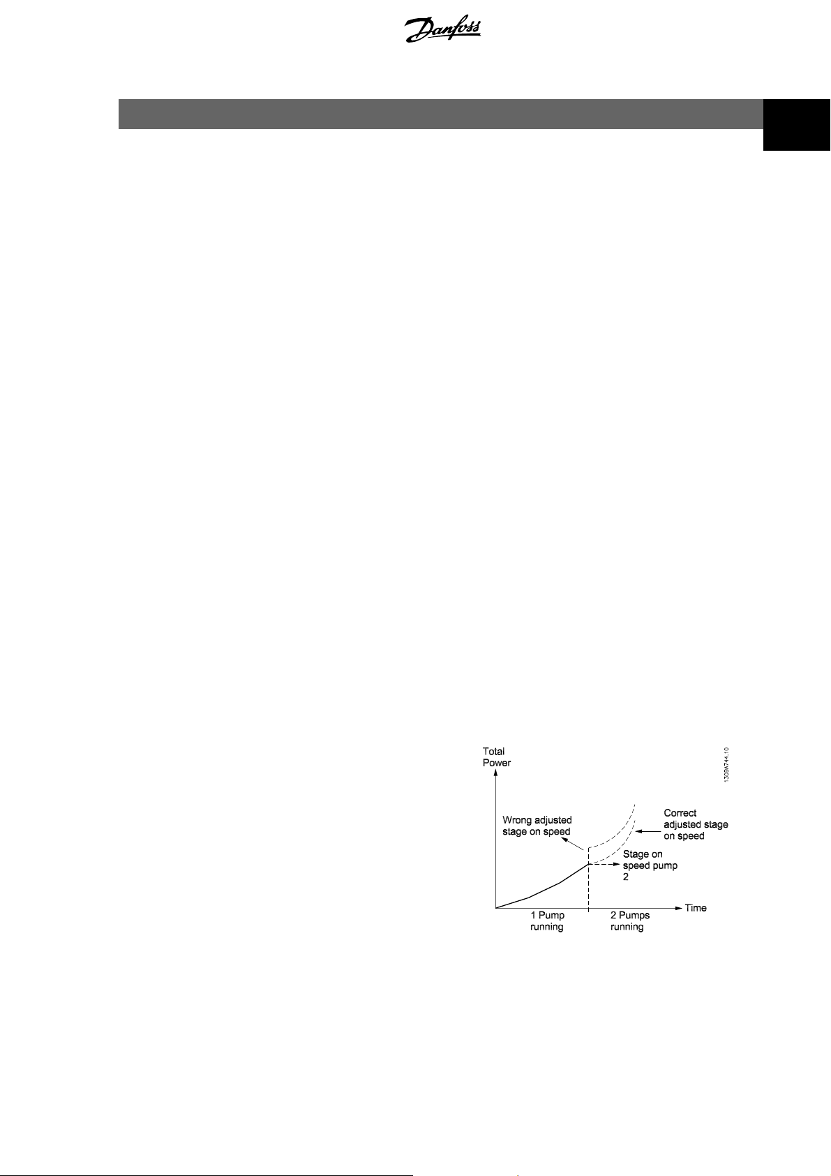
Compared to traditional cascade control the number of running pumps is controlled by speed
instead of feedback. To obtain the highest energy saving the stage on and off speed must be set
correctly according to the system. To understand the principle better, please note figure 1.
The stage on and off speed is set by the user
for each stage. The right speed depends on
the application and the system. In VLT
software version higher than 1.1, the speed
will be auto-tuned by the drive. The right settings can also be determined by using the
Danfoss PC software called MUSEC, which is
downloadable from our homepage: www.danfoss.com
For a start the settings showed in table 1.1 can
be used in most applications.
®
AQUA
Illustration 1.1: Total power consumption.
MN.20.B3.02 - VLT® is a registered Danfoss trademark
1
Page 2
1 Master/Follower Operation VLT® AQUA Drive Application Note
1
Stage 1 40 Min. speed
Stage 2 44 38
Stage 3 46 40
Stage 4 48 42
Table 1.1: Example of stage on and stage off speed
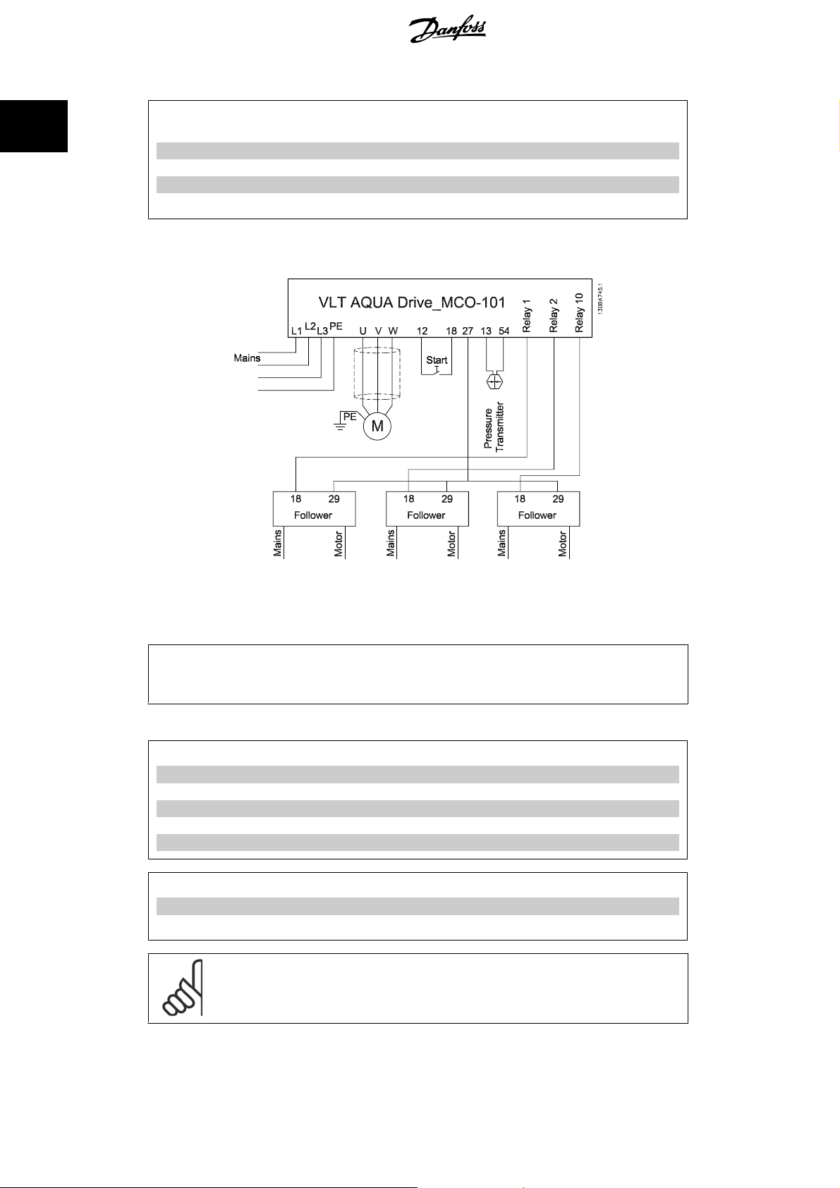
Electrical wiring
Stage on speed [Hz]
(Par. 27-32)
Stage off speed [Hz]
(Par. 27-34)
Illustration 1.2: Electrical wiring. Terminal 2 7 on master drive is us ed as pulse output reference. Terminal
29 on the follower drives is used as pulse input reference. All fo llower drives are conne cted to mains and
motor the same way as the master drive symbolized with the text:
NB!
In the example it is assumed that the pressure transmitter used as feedback sensor, has a range
from 0-10 bar.
Parameter settings:
Display settings - Master drive:
Display Line 1.1 Small 0-20 Reference [1601]
Display Line 1.2 Small 0-21 Feedback [1652]
Display Line 1.3 Small 0-22 Motor current [1614]
Display Line 2 Large 0-23 Frequency [1613]
Display Line 3 Large 0-24 Cascade reference [2791]
Display settings - Follower drives:
Display Line 1.1 Small 0-20 External Reference [1650]
Display Line 3 Large 0-24 Frequency [1613]
NB!
Please note: the format of the analogue input is set using switch S201 below the
LCP.
Mains
and
Motor
.
2
MN.20.B3.02 - VLT® is a registered Danfoss trademark
Page 3

VLT® AQUA Drive Application Note 1 Master/Follower Operation
Basic settings for both Master and Follower drives:
1
Parameters:
Change from RPM to Hz as speed unit 0-02
Motor rated power 1-20 / par. 1-21 (kW / HP)
Motor rated voltage 1-22
Motor Current 1-24
Motor Rated Speed 1-25
Motor Rotation Check 1-28 Check rotation direction
Enable Automatic Motor Adaptation 1-29
Ramp Up Time 3-41 (5 sec.* Depending on size) Must be the same in
Master and Follower!
Ramp Down Time 3-42 (5 sec.* Depending on size) Must be the same in
Master and Follower!
Motor Speed Low Limit [Hz] 4-12 (30 Hz)
Motor Speed High Limit [Hz] 4-14 (50 Hz) Must be the same in Master and Follower!
Settings for the Master drive only
1. Use the
feedback settings and the PID controller.
2. Set up the master configuration in par. 27-**
Closed Loop
Wizard under
Quick Menu_Function Setup
, to easily set up the
Configuration mode 27-10 Master/Follower
Set number of drives 27-11 4
Set the staging speed according to table 1.1 27-3*
Configure Relay 1 27-70 Drive 2 Enable
Configure Relay 2 27-70 Drive 3 Enable
Configure Relay 10 27-70 Drive 4 Enable
Minimum Reference 3-02 0 [bar]
Maximum Reference 3-03 10 [bar]
Terminal 27 Mode 5-01 Output [1]
Terminal 27 Digital Output 5-30 Pulse output [55]
Terminal 27 Pulse Output Variable 5-60 Cascade Reference [116]
Pulse Output Maximum Frequency #27 5-62 5000 [Hz]
Settings for the Follower drives only
Set Reference 1 Source 3-15 Pulse input 29 [7]
Set Terminal 29 Digital Input 5-13 Pulse input [32]
Set Term. 29 Low Frequency 5-50 0 [Hz]
Set Term. 29 high frequency 5-51 5000 [Hz]
Autotuned Stage on/off Speeds
If stage on/off autotune is enabled in P27-30, the speed in table 1.1 will be auto optimised during
operation and ensure optimised performance.
MN.20.B3.02 - VLT® is a registered Danfoss trademark
3
Page 4

1
1 Master/Follower Operation VLT® AQUA Drive Application Note
Operation
When the system is set to operation, the master drive will automatically run
drives running with the needed number of pumps depending on the demand. If, for some reason
the user wants to prioritize which motors should be preferred, it is possible to prioritize the
pumps in par. 27-16 in three levels. (Priority 1, Prior ity 2 and spare p ump). Pumps with priority 2
will only be staged on when there is no priority 1 pump available.
It might be necessary to fine adjust the
if not auto tuned.
stage on/off
speed to optimise the energy consumption,
time balance
with all
4
MN.20.B3.02 - VLT® is a registered Danfoss trademark
 Loading...