

Page 1

At the end of this document you will find links to products related to this catalog. You can go directly to our shop by
clicking HERE. HERE
Page 2

MAKING MODERN LIVING POSSIBLE
Operating Instructions
VLT® Active Filter AAF006
www.danfoss.com/drives
Page 3

Page 4

Contents
1 Introduction
4
1.1 Purpose of the Manual
4
1.2 Additional Resources
4
1.3 Product Overview
4
1.3.1 Working Principle 4
1.3.2 IEEE519 Compliance 5
1.4 Ordering Information
6
1.4.1 Filter Configurator 6
1.4.2 Ordering Form Type Code 6
2 Safety
7
2.1 Safety Symbols
7
2.2 Qualified Personnel
7
2.3 Safety Precautions
7
3 Mechanical Installation
8
3.1 Pre-installation
8
3.1.1 Planning the Installation Site 8
3.1.2 Receiving the Active Filter 8
3.1.3 Transportation and Unpacking 8
3.1.4 Lifting 8
3.1.5 Mechanical Dimensions 9
3.2 Mechanical Installation
11
3.2.1 Tools Needed 11
3.2.2 Clearance Requirements 11
3.2.3 Power Terminal Locations 12
3.2.4 Cooling and Airflow 13
3.2.5 Gland/Conduit Entry - IP21 (NEMA 1) and IP54 (NEMA12) 14
4 Electrical Installation
15
4.1 Safety Instructions
15
4.2 Electrical Installation
15
4.2.1 Power Connections 15
4.2.2 Grounding 16
4.2.3 EMC Interference 17
4.2.4 Extra Protection (RCD) 18
4.2.5 RFI Switch 18
4.2.6 Torque 18
4.2.7 Current Transformer (CT) 18
4.2.8 Auto CT Detection 22
Contents Operating Instructions
MG90V302 Danfoss A/S © 09/2014 All rights reserved. 1
Page 5

4.2.9 Summation Transformers 23
4.2.10 Operating with Capacitor Banks 24
4.2.11 Fuses 26
4.2.12 Mains Disconnectors 26
4.2.13 Control and CT Cable Routing 26
4.2.14 Control Wire Installation 26
4.2.15 Unscreened Control Wires 27
4.2.16 Electrical Installation, Control Cables 28
4.3 Installation Checklist
29
5 User Interface
30
5.1 Local Control Panel Operation
30
5.1.1 Modes of Operation 30
5.1.2 How to Operate Graphical LCP (GLCP) 30
5.1.3 Changing Data 33
5.1.4 Changing a Text Value 33
5.1.5 Changing a Group of Numeric Data Values 33
5.1.6 Changing of Data Value, Step-by-Step 33
5.1.7 Readout and Programming of Indexed Parameters 33
5.1.8 Quick Transfer of Parameter Settings with the LCP 34
5.1.9 Initialisation to Default Settings 34
5.1.10 RS485 Bus Connection 35
5.1.11 Connection to a PC 35
6 Applications and Basic Programming
36
6.1 Paralleling of Active Filters
36
6.2 Programming
38
6.3 Description of Parameters
41
6.4 0-** Operation/Display
41
6.5 5-** Digital I/O Mode
46
6.6 8-** General Settings
48
6.7 14-2* Trip Reset
50
6.8 15-** Drive Information
52
6.9 16-** Data Readouts
56
6.10 300-** AF Settings
58
6.11 301-** AF Readouts
61
6.12 Parameter Lists
62
6.12.1 Default Settings 62
6.12.2 0-** Operation/Display 63
6.12.3 5-** Digital In/Out 64
6.12.4 8-** Comm. and Options 64
Contents Operating Instructions
2 Danfoss A/S © 09/2014 All rights reserved. MG90V302
Page 6

6.12.5 14-** Special Functions 65
6.12.6 15-** FC Information 65
6.12.7 16-** Data Readouts 67
6.12.8 300-** AF Settings 68
6.12.9 301-** AF Readouts 68
7 RS485 Installation and Set-up
69
7.1 Installation and Set-up
69
7.2 Network Configuration
70
7.3 FC Protocol Message Framing Structure
70
7.3.12 Conversion 73
7.4 How to Access Parameters in Modbus RTU
74
8 Maintenance, Diagnostics and Troubleshooting
75
8.1 Maintenance and Service
75
8.2 Warning and Alarm Types
75
8.3 Active Filter Warning and Alarm Definitions
76
9 Specifications
81
9.1 Power Rating
81
9.2 Derating for Altitude and Ambient Temperature
84
9.3 Acoustic Noise
84
10 Appendix
85
10.1 Abbreviations and Conventions
85
Index
86
Contents Operating Instructions
MG90V302 Danfoss A/S © 09/2014 All rights reserved. 3
Page 7
1 Introduction
1.1 Purpose of the Manual
These operating instructions provide information for safe
installation and commissioning of the filter.
The operating instructions are intended for use by
qualified personnel.
Read and follow the operating instructions to use the filter
properly, and pay particular attention to the safety
instructions and general warnings. Keep these operating
instructions available with the filter at all times.
VLT® is a registered trademark.
1.2 Additional Resources
Resources available to understand advanced active filter
functions and programming:
•
The VLT® Advanced Active Filter Service Manual
provides information on troubleshooting and
testing for field service technicians, as well as
disassembly and assembly instructions.
1.3
Product Overview
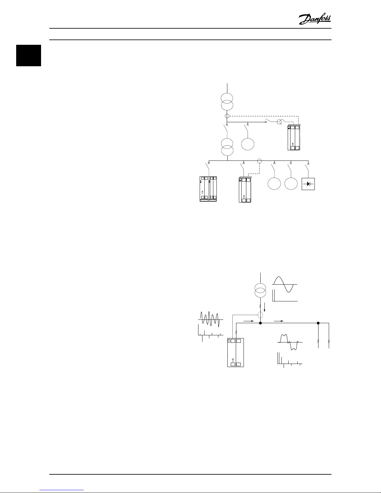
1.3.1 Working Principle
The VLT® Advanced Active Filter is used for harmonic
current mitigation and reactive current compensation. The
unit can integrate with various systems and applications as
a centrally installed filter or be combined with a VLT
®
frequency converter as a packaged low harmonic drive
solution.
M
M M
130BB717.10
Illustration 1.1 Multiple Working Environments
The active shunt filter monitors all 3-phase line currents
and processes the measured current signal via a digital
signal processor system. The filter then compensates by
actively imposing signals in counter phase to the
unwanted elements of the current (harmonic distortion).
130BB718.10
Illustration 1.2 Active Filter Principles
The filter sets different IGBT switches in real time feeding a
DC voltage into the grid, which creates counter phase
signals. A built-in LCL filter smooths the compensated
current waveform, ensuring that the IGBT switching
frequency and DC component is not imposed to the grid.
The filter operates on generator or transformer supply and
can reduce individual motor loads, non-linear loads, or
Introduction
Operating Instructions
4 Danfoss A/S © 09/2014 All rights reserved. MG90V302
1
Page 8
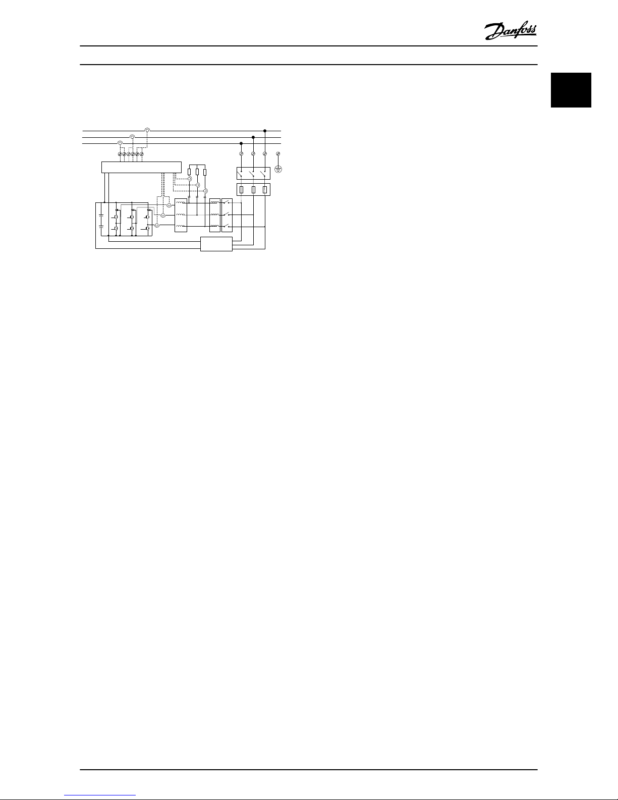
mixed loads. Non-linear loads (diode feed loads) must hold
AC coils to protect against overcurrent of the input diodes.
Control
Manual
Disconnect
Fuse
Option
Soft charge
circuit
130BB719.10
Illustration 1.3 Block Diagram
The filter allows either overall or selective harmonic
compensation modes. In overall compensation mode, all
harmonics are reduced. In this mode, the filter balances
the load to reduce uneven load distribution among the 3
phases. The steady state performance allows compensation
of harmonics to the 40th order, but the ultra-quick current
injection allows the filter to compensate flicker and other
quick and short-term phenomena. In selective mode, the
user can program acceptable individual harmonic levels
between 5th and 25th order. In selective mode, the filter
does not reduce harmonics in twos and threes, and does
not support phase load balancing and flicker reduction.
See parameter 300-00 Harmonic Cancellation Mode.
Program the filter priority as either reactive current or
harmonic compensation. If harmonic compensation is first
priority, the filter uses the current needed for harmonic
reduction and uses energy for reactive current correction
only if there is excess. The filter automatically and continuously assigns energy between first and second priority to
provide the highest possible mitigation of both reactive
and harmonic compensation. The power factor is
optimised continuously and the supply transformer is used
to its maximum capacity. See parameter 300-01 Compen-
sation Priority.
The active filter has an optional RFI filter for Class A1 equal
to category C2.
1.3.2
IEEE519 Compliance
The active filter is designed to meet IEEE519 recommendation for Isc/Il >20 for even individual harmonic levels.
The filter has a progressive switching frequency that
creates a wide frequency spread, giving lower individual
harmonic levels above the 50th harmonic level.
Introduction
Operating Instructions
MG90V302 Danfoss A/S © 09/2014 All rights reserved. 5
1
1
Page 9
1.4 Ordering Information
1.4.1 Filter Configurator
Use the ordering number system to design an active filter according to the application requirements. For the VLT® Active
Filter AAF 006 Series, it is possible to order standard filters and filters with integral options by sending a type code string
describing the product to the local Danfoss sales office. For example: AAF006A190T4E21HXXGCXXXSXXXXAXBXCFXXXDX
This section describes each character in the type code. In the example, a standard 190 A active filter in an enclosure with
IP21 protection rating is selected for a 380–480 V net. The internet-based configurator configures the right filter for the right
application and generates a type code string. The configurator automatically generates an 8-digit sales number to be
delivered to the local sales office. It is also possible to establish a project list with several products and send it to a Danfoss
sales representative. The configurator can be found at www.danfoss.com/BusinessAreas/DrivesSolutions/.
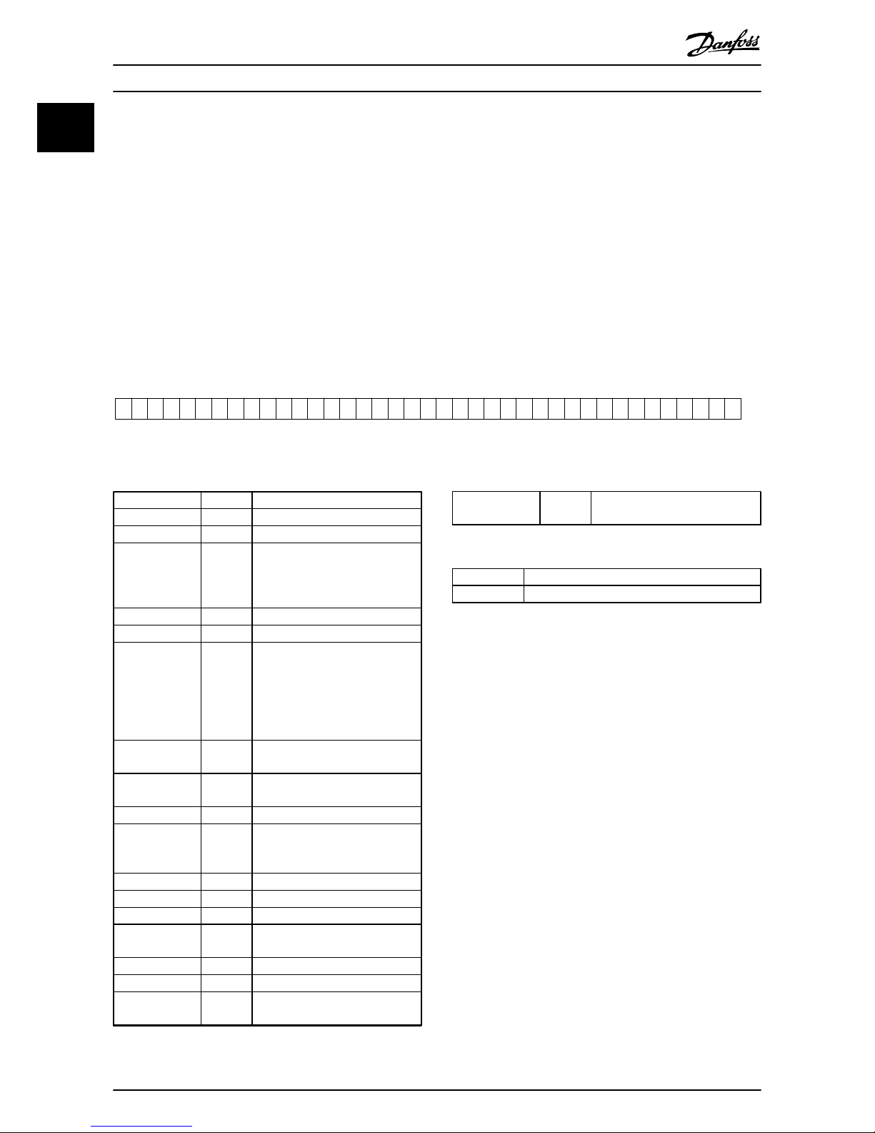
1.4.2 Ordering Form Type Code
130BB504.10
1 2 3 4 5 6 7 8 9 10 11 12 13 14 15 16 17 18 19 20 21 22 23 24 25 26 27 28 29 30 31 32 33 34 35 36 37 38 39
A FA x0 0 A T 4 E H x G C x x x x x x x B x C x x x x xDAS
Illustration 1.4 Type Code Example
Possible choice
Product groups 1-3 AAF
Series 4-6 006
Current rating 7-10 A190: 190 A
A250: 250 A
A310: 310 A
A400: 400 A
Phases 11 T: 3 Phases
Mains Voltage 12 4: 380–480 V AC
Enclosure 13-15 E21: IP21/Nema Type1
E54: IP54/Nema Type 12
E2M: IP21/Nema Type 1 with
mains shield
E5M: IP54/Nema Type 12 with
mains shield
RFI filter 16-17 HX: No RFI filter
H4: RFI filter, Class A1 (optional)
Display (LCP) 19 G: Graphical Local Control Panel
(LCP)
Coating PCB 20 C: Coated PCB
Mains option 21 X: No mains option
3: Mains disconnect and fuse
7: Fuse
Adaptation A 22 Reserved
Adaptation B 23 Reserved
Software release 24-27 Reserved
Software
language
28 Reserved
A options 29-30 AX: No A option
B options 31-32 BX: No B option
C-option configuration
33-37 CFxxx: CO-option occupied with
active filter control card
D options 38-39 DO: 24 V back-up
DX: No options
Table 1.1 Type Code Definitions
176F3535 Backwall cooling kit for D14 (IP54)
176F3537 Backwall cooling kit for E1 (IP54)
Table 1.2 Optional Kits
Introduction
Operating Instructions
6 Danfoss A/S © 09/2014 All rights reserved. MG90V302
1
Page 10
2 Safety
2.1 Safety Symbols
The following symbols are used in this document:
WARNING
Indicates a potentially hazardous situation that could
result in death or serious injury.
CAUTION
Indicates a potentially hazardous situation that could
result in minor or moderate injury. It can also be used to
alert against unsafe practices.
NOTICE
Indicates important information, including situations that
can result in damage to equipment or property.
2.2 Qualified Personnel
Correct and reliable transport, storage, installation,
operation and maintenance are required for the troublefree and safe operation of the active filter. Only qualified
personnel are allowed to install or operate this equipment.
Qualified personnel is defined as trained staff, who are
authorised to install, commission, and maintain equipment,
systems and circuits in accordance with pertinent laws and
regulations. Additionally, the personnel must be familiar
with the instructions and safety measures described in this
document.
2.3
Safety Precautions
WARNING
HIGH VOLTAGE
Active filters contain high voltage when connected to AC
mains input. Failure to perform installation, start-up, and
maintenance by qualified personnel can result in death
or serious injury.
WARNING
DISCHARGE TIME
The active filter contains DC-link capacitors, which can
remain charged even when the filter is not powered.
Failure to wait the specified time after power has been
removed before performing service or repair work can
result in death or serious injury.
Voltage
[V]
Output Current
[A]
Minimum waiting
time
(minutes)
380–480 190–400 20
High voltage can be present even when the warning indicator
lights are off.
Table 2.1 Discharge Time
WARNING
LEAKAGE CURRENT HAZARD
Leakage currents exceed 3.5 mA. Failure to ground the
filter properly can result in death or serious injury.
•
Ensure correct grounding of the equipment by
a certified electrical installer.
WARNING
EQUIPMENT HAZARD
Contact with rotating shafts and electrical equipment
can result in death or serious injury.
•
Ensure that only trained and qualified
personnel perform installation, start up, and
maintenance.
•
Ensure that electrical work conforms to national
and local electrical codes.
•
Follow the procedures in this document.
CAUTION
INTERNAL FAILURE HAZARD
An internal failure in the filter can result in serious injury
when the filter is not properly closed.
•
Before applying power, ensure all safety covers
are in place and securely fastened.
Safety Operating Instructions
MG90V302 Danfoss A/S © 09/2014 All rights reserved. 7
2 2
Page 11
3 Mechanical Installation
3.1 Pre-installation
3.1.1 Planning the Installation Site
NOTICE
Due to the size and clearance requirements of the active
filter, it is important to pre-plan installation. Failure to
do so may result in additional work during and after
installation.
Select the best possible operation site by considering
the following:
•
Ambient temperature conditions.
•
Altitude at installation point.
•
Installation and compensation method.
•
Cooling.
•
Position of the active filter.
•
CT installation point and possibility to reuse
existing CTs.
•
Cable routing and EMI conditions.
•
Ensure the power source supplies the correct
voltage and frequency.
•
If the unit is without built-in fuses, ensure that
the external fuses are rated correctly.
3.1.2
Receiving the Active Filter
When receiving the unit, ensure that the packaging is
intact, and note any damage that may have occurred
during transport. In case of damage, immediately contact
the shipping company to claim the damage.
NOTICE
Damaged packaging can indicate rough transportation
which may have caused interior failures in the unit.
Claim damages even if the exterior of the unit seems
intact.
3.1.3 Transportation and Unpacking
Place the active filter as close as possible to its final installation site before unpacking it. Keep the filter on the pallet
and boxed as long as possible to avoid damage.
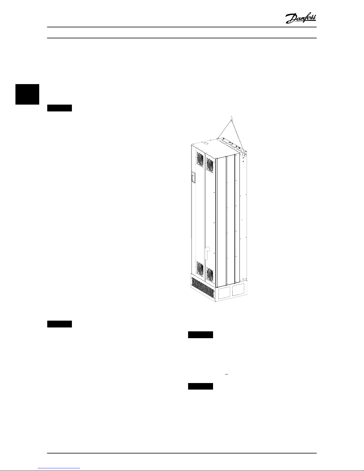
3.1.4
Lifting
Always lift the unit in the dedicated lifting eyes. Use a bar
to avoid bending the lifting holes.
130BB642.10
Illustration 3.1 Recommended Lifting Method for AAF 006,
Enclosure Sizes D14 and E1
NOTICE
The lifting bar must be able to handle the weight of the
unit. See chapter 3.1.5 Mechanical Dimensions for
weights. Maximum diameter for the bar is 25 mm (1
inch). The angle from the top of the unit to the lifting
cable should be > 60°.
NOTICE
The plinth is required to allow airflow to the unit to
provide proper cooling.
Mechanical Installation Operating Instructions
8 Danfoss A/S © 09/2014 All rights reserved. MG90V302
33
Page 12
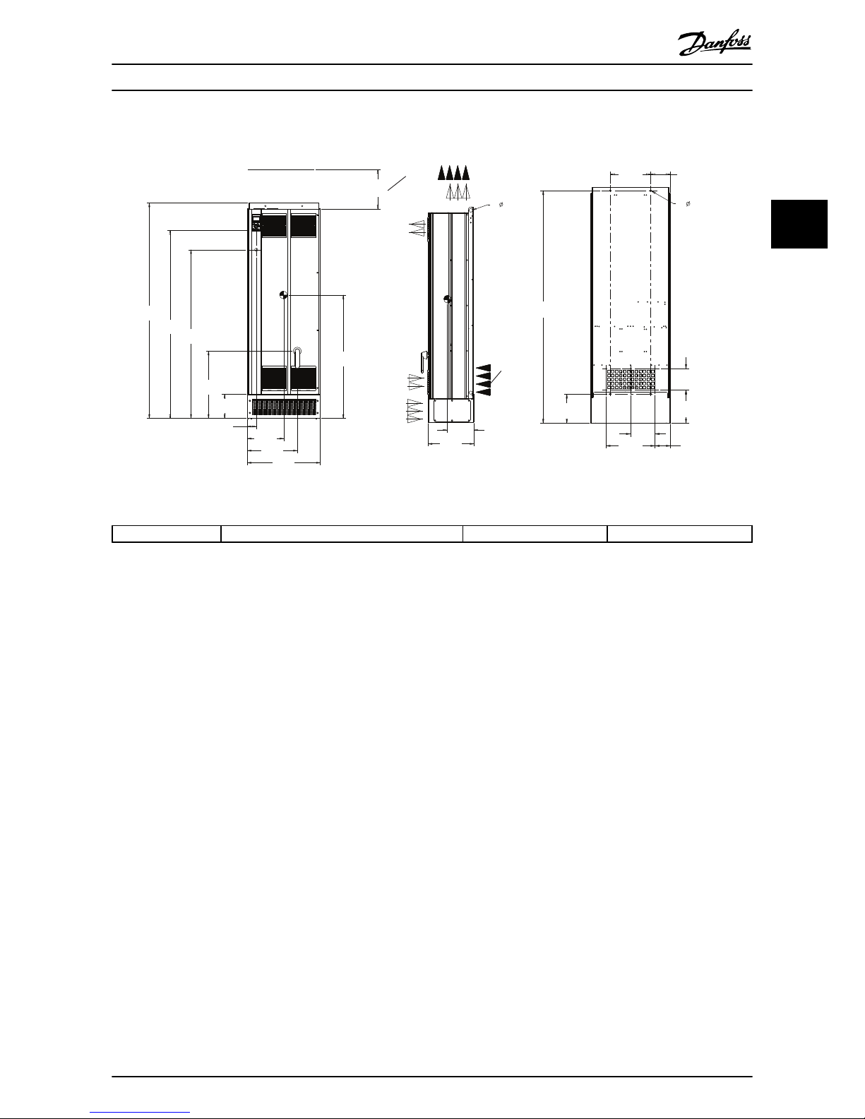
3.1.5 Mechanical Dimensions
1020.1
[40.2]
199.5
[7.9]
1394.0
[54.9]
1552.8
[61.1]
603.8
[23.8]
555.9
[21.9]
377.8
[14.9]
2X
27.0
[1.1]
414.1
[16.3]
74.1
[2.9]
[8.9]
1780.5
[70.1]
221.6
[8.7]
273.2
[10.8]
130BC632.10
117.4
[4.6]
184.5
[7.3]
369.0
[14.5]
148.0
[5.8]
304.0
[12.0]
1755.5
[69.1]
251.0
[9.9]
160.0
[6.3]
2X
13.0
[.5]
221.0
[8.7]
[225.0]
1
2
Illustration 3.2 AAF006 190 A, Enclosure Size D13
1 Minimum clearance from the ceiling 2 Backwall cooling option
Table 3.1 Legend to Illustration 3.2 and Illustration 3.3
Mechanical Installation Operating Instructions
MG90V302 Danfoss A/S © 09/2014 All rights reserved. 9
3 3
Page 13
600.0
[23.6]
493.5
[19.4]
1230.0
[48.4]
2X
27.0
[1.1]
72.2
[2.8]
389.0
[15.3]
[8.9]
283.3
[11.2]
270.9
[11]
198.2
[7.8]
730.7
[28.8]
1394.1
[54.9]
1544.5
[60.8]
2001.0
[78.8]
184.5
[7.3]
369.0
[14.5]
553.5
[21.8]
23.3
[.9]
249.1
[9.8]
160.0
[6.3]
130BC633.10
225.0
1
2
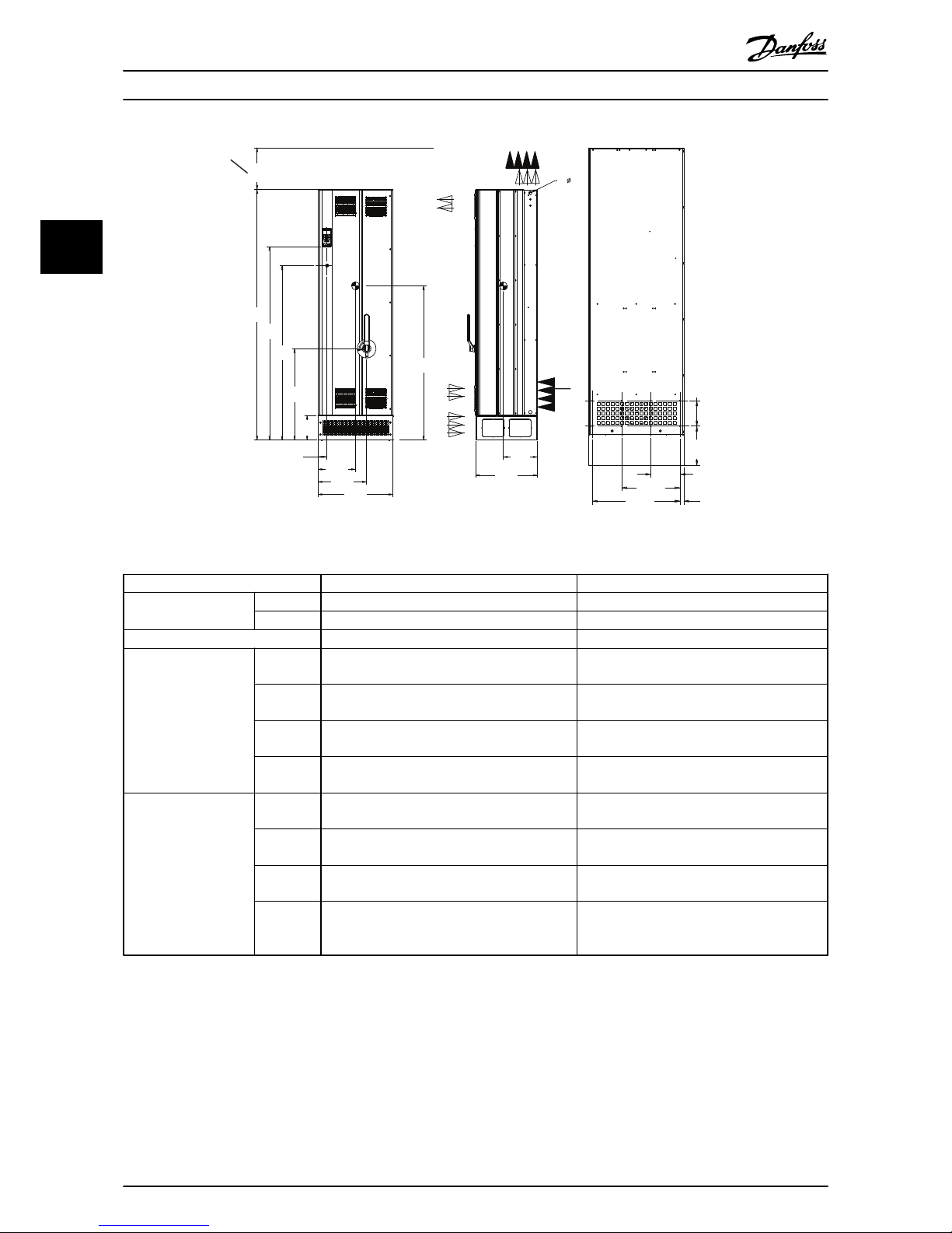
Illustration 3.3 AAF006 250-400 A, Enclosure Size E1
Enclosure D14 E1
Enclosure protection
IP 21/54 21/54
NEMA Type 1/12 Type 1/12
Nominal current rate
190 A 250 A, 310 A, 400 A
Shipping dimensions Height
(mm/in.)
750/29.5 864/34
Width
(mm/in.)
737/29 737/29
Depth
(mm/in.)
1943/76.5 2203/86.7
Weight (kg/
lbs.)
283/623.9 500/1102.3
Unit dimensions Height
(mm/in.)
1780/70 2000/78.7
Width
(mm/in.)
600/23.6 600/23.6
Depth
(mm/in.)
380/14.9 494/19.4
MaximumWeight (kg/
lbs.)
238/524.7 453/998.7
Table 3.2 Mechanical Dimensions
Mechanical Installation
Operating Instructions
10 Danfoss A/S © 09/2014 All rights reserved. MG90V302
33
Page 14
3.2 Mechanical Installation
Before installing the active filter, examine the mechanical
drawings in chapter 3.1.5 Mechanical Dimensions to become
familiar with the space demands.
3.2.1 Tools Needed
To perform the mechanical installation, the following
tools are needed:
•
Drill with a 10 or 12 mm drill bit.
•
Tape measure.
•
Screw driver.
•
Wrench with 7–17 mm metric sockets.
•
Wrench extensions.
•
Sheet metal punch for conduits or cable glands.
•
Lifting bar to lift the unit (rod or tube maximum
Ø 25 mm/0.9 in., able to lift minimum 1000 kg/
2205 lbs.).
•
Crane or other lifting aid to place the unit in
position.
•
Torx T50 tool.
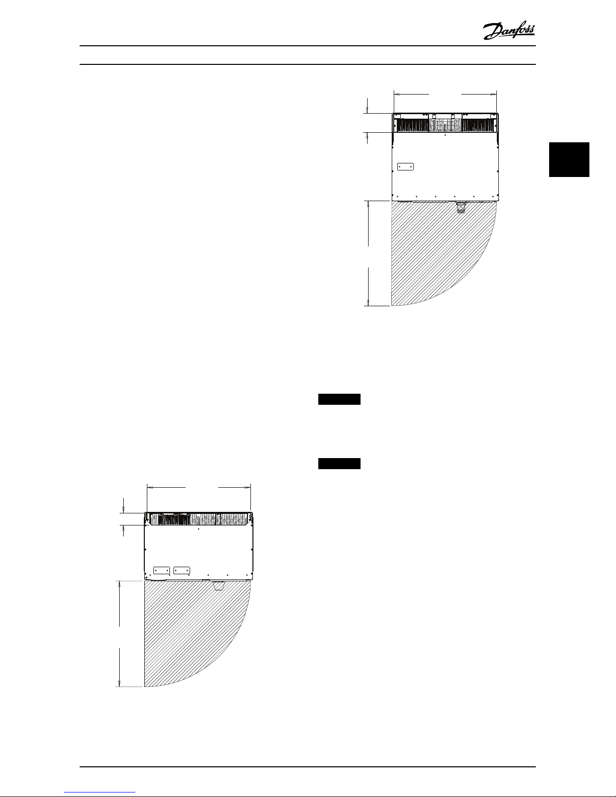
3.2.2
Clearance Requirements
Space
Ensure proper space above and below the unit to allow
airflow and cable access. In addition, ensure adequate
space in front of the unit for the door to open
(Illustration 3.4, Illustration 3.5).
67.3
[2.7]
575.9
[22.7]
574.2
[22.6]
130BC634.10
Illustration 3.4 Door Clearance IP21/IP54 Enclosure Type, Size
D14
105.7
[4.2]
577.4
[22.7]
576.7
[22.7]
130BC635.10
Illustration 3.5 Door Clearance, IP21/IP54 Enclosure Type, Size
E1
Wire access
Ensure that proper cable access including the necessary
bending allowance.
NOTICE
Power cables are heavy and difficult to bend. To make
installation easier, consider the optimum position of the
unit before delivery.
NOTICE
All cable lugs/shoes must mount within the width of the
terminal bus bar.
Mechanical Installation Operating Instructions
MG90V302 Danfoss A/S © 09/2014 All rights reserved. 11
3 3
Page 15
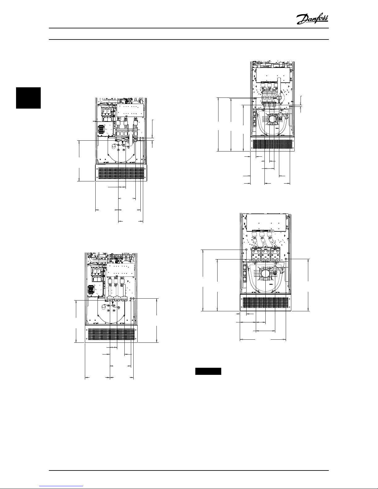
3.2.3 Power Terminal Locations
Consider the position of the terminals when designing for
cable access. See Illustration 3.6, Illustration 3.7,
Illustration 3.8, and Illustration 3.9
88.0
[3.5]
204.0
[8.0]
289.7
[11.4]
29.0
[1.1]
266.2
[10.5]
476.0
[18.7]
259.7
[10.2]
130BC636.10
Illustration 3.6 Terminal Location of D14 with Disconnect
284.1
[11.2]
83.7
[3.3]
167.2
[6.6]
241.9
[9.5]
271.9
[10.7]
505.0
[19.9]
486.0
[19.1]
130BC637.10
Illustration 3.7 Terminal Location of D14 without Disconnect
65.0
[2.6]
130.0
[5.1]
343.0
[13.5]
19.6
[.8]
628.7
[24.8]
194.0
[7.6]
75.0
[3.0]
719.1
[28.3]
389.0
[15.3]
730.7
[28.8]
130BC638.10
Illustration 3.8 Terminal Location of E1 with Disconnect
719.1
[28.3]
609.1
[24.0]
75.0
[3.0]
188.0
[7.4]
112.0
[4.4]
224.0
[8.8]
537.0
[21.1]
605.6
[23.8]
130BC639.10
Illustration 3.9 Terminal Location of E1 without Disconnect
NOTICE
Each terminal allows up to 4 cables with cable lugs or
use of a standard box lug. Ground is connected to the
relevant termination point in the unit.
Mechanical Installation Operating Instructions
12 Danfoss A/S © 09/2014 All rights reserved. MG90V302
33
Page 16
3.2.4 Cooling and Airflow
There are different ways to cool the active filter:
•
Use the cooling ducts in the top and bottom of
the unit
•
Take air into the back of the unit
•
Combine top, bottom, and back airflow
Back cooling
The active filter has a back channel cooling system where
85% of all heat is ducted via an IP54 segregated back
channel. This reduces the needed airflow inside the
enclosure and ensures less moisture and dust across vital
components.
The back channel air is normally ventilated via the plinth
inlet and ducted out the top of the enclosure. The design
of the back channel can also take air from the control
room and duct it back out again. This is supported to ease
stress on the control room air conditioner and conserve
energy. To support a backwall inlet, the unit air inlet has to
be blocked via an optional cover and the air outlet ducted
via an optional top duct.
NOTICE
The active filter fan runs for the following reasons:
•
Active filter running.
•
Specific heat sink temperature exceeded (power
size dependent).
•
Specific power card ambient temperature
exceeded (power size dependent).
•
Specific control card ambient temperature
exceeded.
Once the fan is started, it runs for a minimum of 10
minutes.
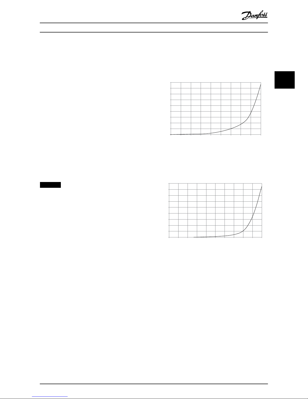
External ducts
If additional duct work is added externally to the
enclosure, the pressure drop in the ducting must be
calculated. Use Illustration 3.10 and Illustration 3.11 to
derate the unit according to the pressure drop.
90
80
70
60
50
40
30
20
10
0
0 0.5 4.9 13 27.3 45.9 66 89.3 115.7 147
(%)
(Pa)
Pressure Increase
Filter Derating
130BB932.10
Illustration 3.10 Enclosure Size D, Derating vs. Pressure
Change
Air Flow: 450 cfm (765 m3/h)
90
80
70
60
50
40
30
20
10
0
(%)
Filter Derating
0 0 0.1 3.6 9.8 21.5 43.4 76 237.5 278.9
(Pa)
Pressure Change
130BB933.10
147.1
Illustration 3.11 Enclosure Size E, Derating vs. Pressure Change
Air Flow: 725 cfm (1230 m3/h)
Mechanical Installation Operating Instructions
MG90V302 Danfoss A/S © 09/2014 All rights reserved. 13
3 3
Page 17
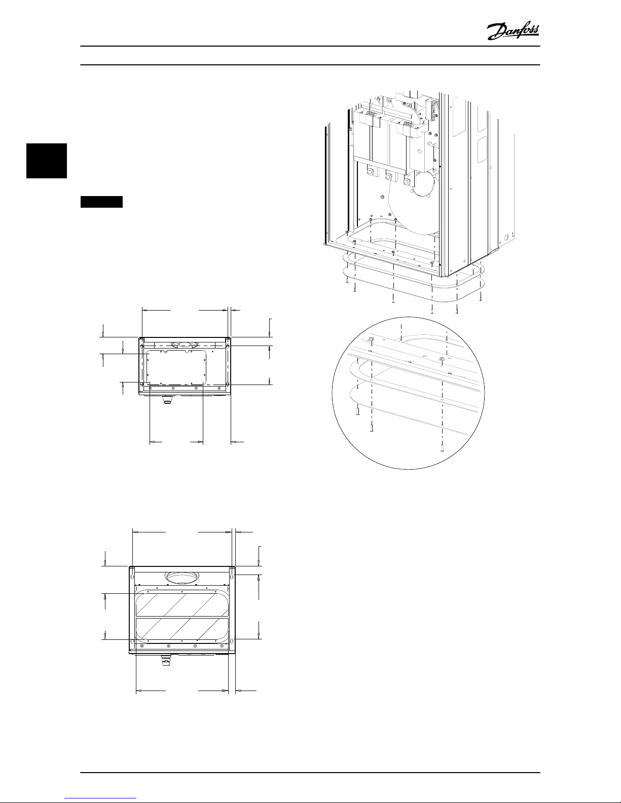
3.2.5 Gland/Conduit Entry - IP21 (NEMA 1)
and IP54 (NEMA12)
Cables are connected through the gland plate from the
bottom. Remove the plate and plan where to place the
entry for the glands or conduits. Illustration 3.12 and
Illustration 3.13 show the gland plate openings in bottom
views.
NOTICE
The gland plate ensures the specified protection degree,
and enables proper cooling of the unit. If the gland plate
is not mounted, the unit may trip on Alarm 69, Pwr. Card
Temp.
55.9
[2.2]
257.0
[10.1]
21.9
[.9]
560.0
[22.0]
110.6
[4.4]
182.8
[7.2]
181.9
[7.2]
350.0
[13.8]
130BC640.10
Illustration 3.12 Enclosure Size D14, Bottom View
361.7
[14.2]
20.0
[.8]
560.0
[22.0]
154.8
[6.1]
257.6
[10.1]
40.0
[1.6]
520.0
[20.5]
48.9
[2]
Illustration 3.13 Enclosure Size E1, Bottom View
130BB736.11
Illustration 3.14 Mounting of Base Plate, E1
The base plate of the enclosure size E can be mounted
from either inside or outside of the enclosure, allowing
flexibility in the installation process. If mounted from the
bottom, the glands and cables can be mounted before the
unit is placed on the pedestal.
Mechanical Installation Operating Instructions
14 Danfoss A/S © 09/2014 All rights reserved. MG90V302
33
Page 18
4 Electrical Installation
4.1 Safety Instructions
See chapter 2 Safety for general safety instructions.
CAUTION
SHOCK HAZARD
The active filter can cause a DC current in the PE
conductor.
•
When a residual current-operated protective
device (RCD) is used for protection against
electrical shock, only an RCD of Type B is
permitted on the supply side.
Failure to follow the recommendation means the RCD
may not provide the intended protection.
4.2 Electrical Installation
4.2.1 Power Connections
Cabling and fusing
NOTICE
All cabling must comply with national and local
regulations on cable cross-sections and ambient
temperature. UL applications require 75 °C copper
conductors. 75° and 90 °C copper conductors are
thermally acceptable for use in non-UL applications.
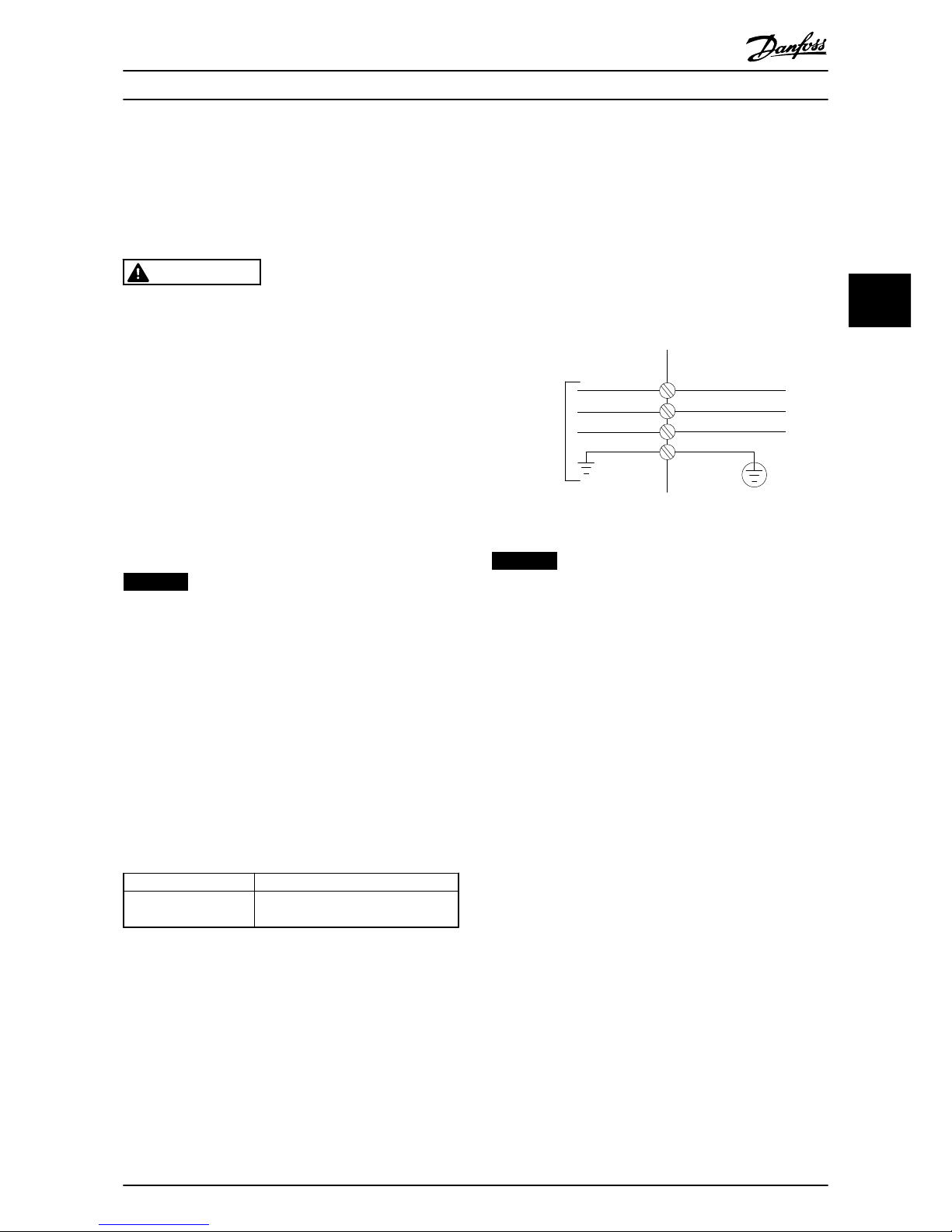
The power cable connections are situated as shown in
Illustration 4.1. The mains connection is fitted to the mains
switch if this is included. Dimension the cable cross-section
in accordance with the filter current rating, including skin
and proximity effects, derating, and local legislation.
Connect mains to terminals 91, 92 and 93. Connect ground
to the terminal on the immediate right of terminal 93.
Terminal number Function
91, 92, 93
94
Mains R/L1, S/L2, T/L3
Ground
Table 4.1 Mains and Ground Connections
The conductor predominantly carries currents of high
frequencies so the distribution of current is not evenly
dispersed throughout the cross-section of the conductor.
This is due to 2 independent effects known as skin effect
and proximity effect. Both require derating and,
consequently, the mains cable of the active filter is rated at
a higher current than the filter rating itself.
3 Phase
power
input
130BA026.10
91 (L1)
92 (L2)
93 (L3)
95 PE
Illustration 4.1 Mains Connection Diagram
NOTICE
It is insufficient to rate the power cable for the filter
current rating alone due to skin and proximity effects.
The required derating is calculated as 2 separate factors:
•
The skin factor depends on frequency of current,
cable material, and cable dimensions.
•
The proximity factor depends on the number of
conductors, diameters and distance between the
individual cables.
The proximity effect is depending on the number of
conductors, diameters and distance between the individual
cables.
The optimised mains cable is:
•
Copper wires.
•
Single conductors.
•
Bus bars.
Electrical Installation Operating Instructions
MG90V302 Danfoss A/S © 09/2014 All rights reserved. 15
4 4
Page 19
Copper affects skin less than aluminum, and bus bars have a larger surface area than cables, reducing the skin effect factor.
Proximity effects of single conductors are negligible.
The cable specifications in Table 4.2 take both skin and proximity effects into account:
Filter Minimum CU wire
mm2 (AWG)
Equivalent RMS
cable for CU
Minimum ALU wire
mm2 (AWG)
Equivalent RMS
current for ALU
Maximum wire
mm2 (AWG)
190 A
70 mm2 (2/0)
225 A
95 mm2 (3/0)
240 A
2*150 mm2 (2*300 MCM)
250 A
120 mm2 (4/0)
295 A
150 mm2 (300 MCM)
315 A
4x240 mm2 (4x500 MCM)
310 A
240 mm2 (500 MCM)
365 A
2*95 mm2 (2*3/0)
390 A
4x240 mm2 (4x500 MCM)
400 A
2*95 mm2 (2*3/0)
470 A
2*150 mm2 (2*300 MCM)
500 A
4x240 mm2 (8x900 MCM)
Table 4.2 Allowed Active Filter Mains Cable with Typical Cable Manufacturer Data
Due to the built-in LCL filter, the unit does not feed the main wire with high dU/dt signals. Doing so reduces the radiated
emission through the mains cable. Cable screen/shielding can thus be omitted allowing the mains cables to be connected
without considering EMC requirements.
The active filter can run at long cable runs. Cable length is limited by the voltage drop. It is advised to keep the cable
lengths to less then 200 m.
Active filters have either built-in or customer-supplied fuses. See chapter 4.2.11 Fuses for fuse recommendations. Always
ensure proper fusing according to local regulation.
4.2.2
Grounding
Consider the following basic issues when installing an
active filter, to obtain electromagnetic compatibility (EMC):
•
Safety grounding: The active filter has leakage
current and must be grounded appropriately for
safety reasons. Apply local safety regulations.
•
High-frequency grounding: Keep the ground wire
connections as short as possible.
•
Use high-strand wire to reduce electrical
interference.
•
Do not use pigtails.
Connect the different ground systems at the lowest
possible conductor impedance. Obtain the lowest possible
conductor impedance by keeping the conductor as short
as possible and using the greatest possible surface area.
The metal cabinets of the different devices are mounted
on the enclosure back plate using the lowest possible high
frequency impedance. This avoids having different high
frequency voltages for the individual devices and avoids
the risk of radio interference currents running in
connection cables that may be used between the devices.
The radio interference is reduced. To obtain a low HF
impedance, use the fastening bolts of the devices as a
high-frequency connection to the back plate. Remove any
insulating paint or similar substances from the fastening
points.
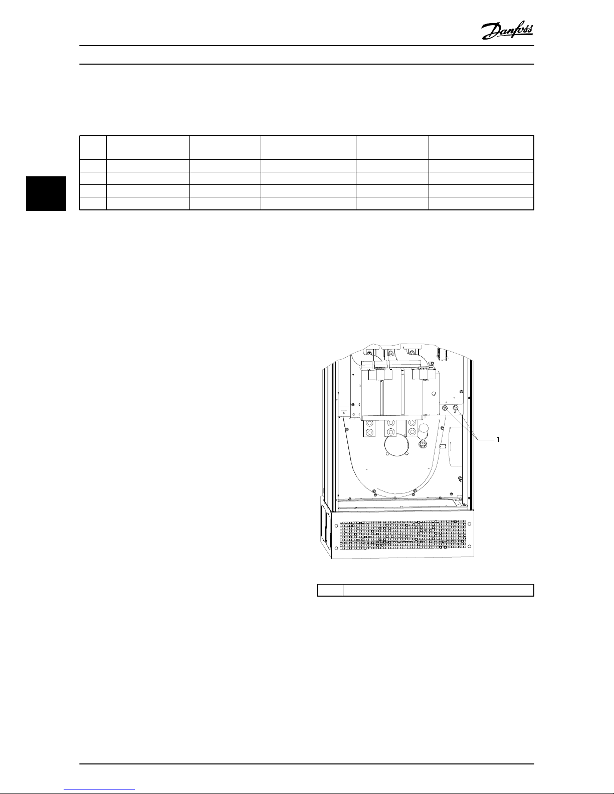
1
130BB739.11
1
Ground terminals
Illustration 4.2
Electrical Installation Operating Instructions
16 Danfoss A/S © 09/2014 All rights reserved. MG90V302
44
Page 20
4.2.3 EMC Interference
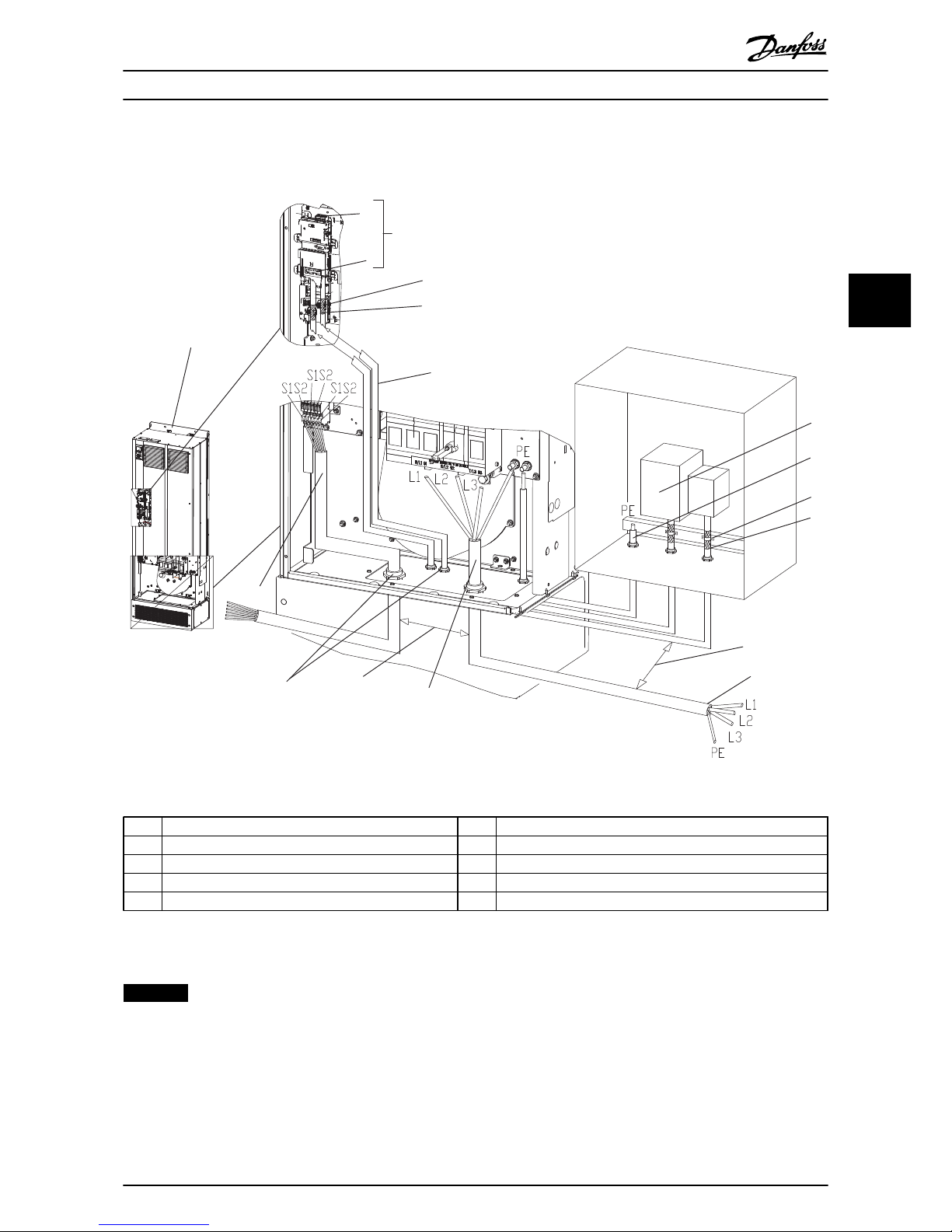
1
2
A
B
3
4
4
5
6
3
4
7
8
8
7
9
10
130BC643.10
1 Advanced active filter (AAF) 6
Potential equalisation wire [minimum 16 mm2/AWG 6]
2 Customer control termination points for options A and B 7 Clearance, minimum 200 mm (7.9 in)
3 Cable clamp 8 Mains, 3-phase and reinforced PE
4 Screened control wiring 9 Cable gland
5 Customer control input 10 External current transformer connections
Illustration 4.3 EMC-correct Installation
NOTICE
EMC INTERFERENCE
Use screened cables for control wiring. Separate AAF mains input cable from other cables and control wiring. Minimum
200 mm (7.9 in) clearance between mains and control cables is required. Maximise this clearance to minimise EMC
emissions. Doing so reduces the risk of interference between the AAF and other electronic devices.
Electrical Installation Operating Instructions
MG90V302 Danfoss A/S © 09/2014 All rights reserved. 17
4 4
Page 21
4.2.4 Extra Protection (RCD)
ELCB, RCD, GFCI relays or multiple protective groundings
are often used as extra protection, or needed to provide
compliance with local safety regulations. In case of a
ground fault, a DC component may develop in the fault
current. Observe local regulations when using ELCB relays.
To reassure effective protection and unintended tripping of
protective relays, all relays must be suitable for protection
of 3-phase equipment with active current infeed and for a
brief discharge during power-up. Use a relay type with
adjustable trip amplitude and time characteristics. Select a
current sensor with sensitivity of more then 200 mA and
not less than 0.1 s operation time.
4.2.5
RFI Switch
Mains supply isolated from ground (IT mains)
If the active filter is supplied from an isolated mains source
(IT mains, floating delta and grounded delta) or TT/TN-S
mains with grounded leg, the RFI switch is recommended
to be turned off (OFF) 1) via 14-50 RFI Filter on the unit.
For further reference, see IEC 364-3. In OFF mode, the
internal RFI capacities between the chassis and the
intermediate circuit are cut off to avoid damage to the
intermediate circuit. Refer to the application note VLT® on
IT mains. It is important to use isolation monitors that are
capable for use together with power electronics (IEC
61557-8).
NOTICE
Marine grids are typically IT type grids.
4.2.6 Torque
Correct torque is imperative for all electrical connections.
Incorrect torque results in a bad electrical connection.
Torque values are provided in Table 4.3.
Enclosure size Torque Bolt size
D 19 Nm (168 in.-lbs.) M10
E 19 Nm (168 in.-lbs.) M10
Table 4.3 Correct Torque Values
Use a torque wrench to ensure correct torque.
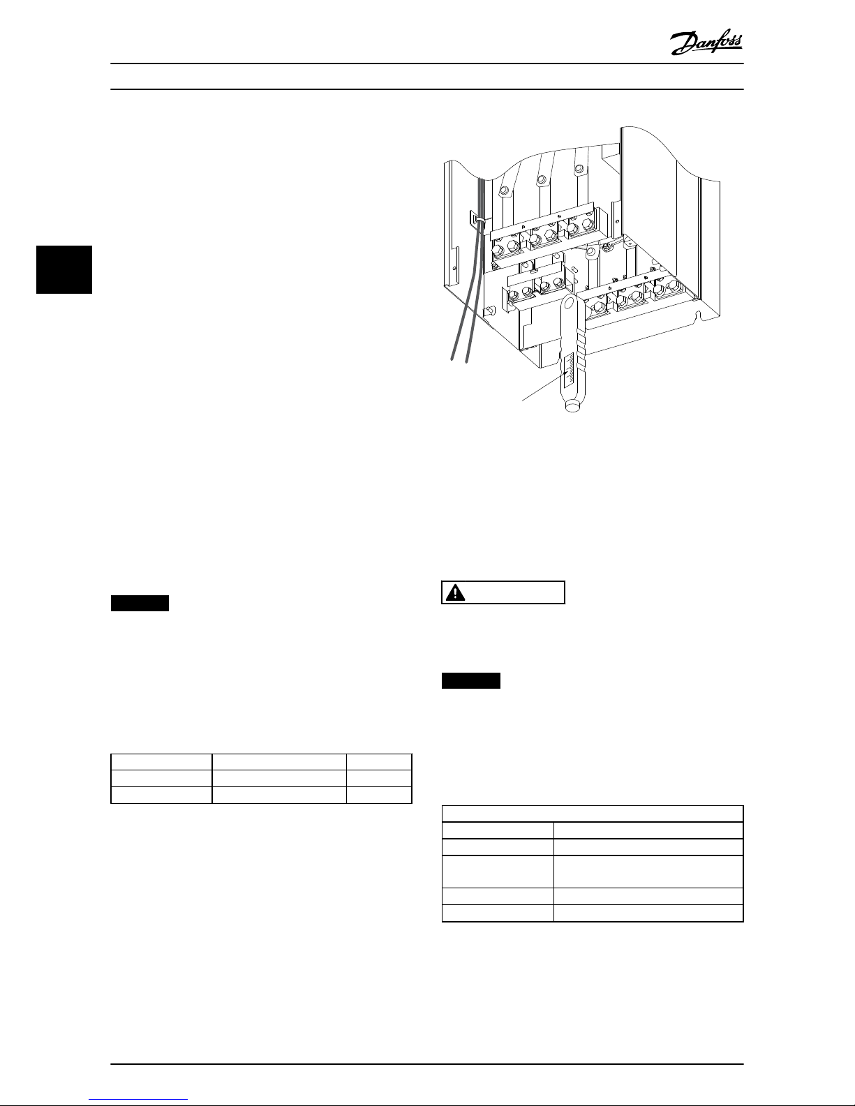
176FA247.12
Nm/in-lbs
-DC 88
+DC 89
R/L1 91
S/L2 92
T/L3 93
U/T1 96
V/T2 97
W/T3
Illustration 4.4 Use a Torque Wrench to Tighten the Bolts
4.2.7
Current Transformer (CT)
The filter operates in close loop operation by receiving
current signals for external current transformers. The
received signal is processed and the filter reacts according
to programmed actions.
CAUTION
Incorrect current transformer connection, installation or
configuration leads to unintended and uncontrollable
behaviour of the filter.
NOTICE
The current transformers are not part of the filter
package and must be purchased separately.
CT specification
The active filter supports most CTs. The CTs must have the
following specifications:
Technical specification of active filter, passive CT
RMS Maximum measured RMS current
Accuracy 0.5% or better (Class 0.5)
Secondary rated
current
1A or 5A (5A is recommended)
Set-up via hardware
Rated frequency 50/60 Hz
Rated power/burden
See Table 4.5 (AAF burden equals 2 mΩ)
Table 4.4 CT Specifications
Electrical Installation
Operating Instructions
18 Danfoss A/S © 09/2014 All rights reserved. MG90V302
44
Page 22
Rated power/
burden [VA]
5 7.5 10 15 30
Impedance of
current CT [Ω]
≤ 0.15 ≤ 0.25 ≤ 0.35 ≤ 0.55 ≤ 1.15
Table 4.5 Rated Power/Burden
NOTICE
All other technical data such as dynamic rated current,
maximal permitted operating voltage, thermal
dimensioning of continuous current, thermal
dimensioning of short-time current, overcurrent limit,
isolation class, working temperature range etc. are
specific values of the system and have to be defined
during the project planning phase of the equipment.
RMS specification
The minimum RMS is determined by the total current that
passes through the current transformer. It is important that
the current sensor is not too small, leading to saturation of
the sensor. Add 10% margin and pick the next following
bigger standard RMS rate. Use current transformers that
have an RMS rating close to the maximum current flowing
through it to allow the highest possible accuracy of the
measurement and so an ideal compensation.
CT burden
To ensure that the current transformer performs according
to specifications, the rated burden should not be above
the true current requirement of the active filter. The
burden of the CT depends on the wire type and the cable
length between the CT and the filter CT connection
terminal. The filter itself contributes with 2 mΩ.
NOTICE
The accuracy of the CT is depending on wire type and
length of the cable between filter and current
transformer.
Calculate the required (minimum) CT burden as:
[VA]=25*[Ω/M] *[M]+1.25
[Ω/M] being the cable resistance in Ω/meter, [M] being the
cable length in meters.
Table 4.6 shows the minimum CT burden for different wire
gauge at wire length of 50 m and standard wire resistance
value:
Wire Gauge
[mm2/AWG]
Resistance
[Ω/km]
Wire length
[meters/feet]
Minimum CT
burden [VA]
1.5/#16 13.3 50/164 >16.6
2.5/#14 8.2 50/164 >10.2
4/#12 5.1 50/164 > 6.3
6/#10 3.4 50/164 > 4.2
10/#8 2 50/164 > 2.5
Table 4.6 Minimum CT Burden
For a fixed CT burden, calculate the maximum allowed
wire length as:
[M]=([VA]-1.25)/(25*[Ω/M])
Below the maximum wire length of CT with 2.5 mm2 wires
and resistor value equal 8.2 Ω/km:
Wire Gauge
[mm2/ AWG]
Resistance
[Ω/km]
Minimum CT
burden [VA]
Wire length
[meter/feet]
2.5/#14 8.2 5 <18/60
2.5/#14 8.2 7.5 <30/100
2.5/#14 8.2 10 <42/140
2.5/#14 8.2 15 <67/220
2.5/#14 8.2 30 <140/460
Table 4.7 Maximum CT Wire Length
Example
Calculation example for correct current transformer for an
application with:
RMS=653 A, Distance between filter and CTs of 30 m.
RMS=653*1.1=719 A, CT RMS=750 A. Burden: 30 m@2.5
mm2 wire =>25*0.0082*30+1.25=7.4=>7.5 [VA].
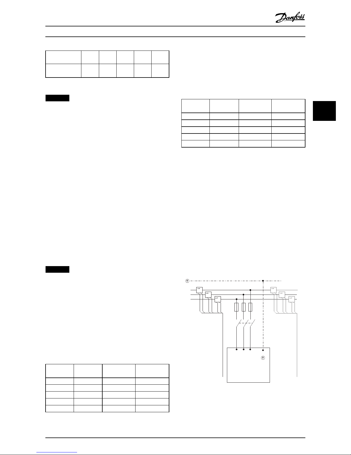
Current transformer installation
The unit only supports 3 CT installations. Install external
CTs on all 3 phases to detect the harmonic content of the
grid. The flow direction of the sensor is indicated by an
arrow in most cases. The arrow points in the direction of
the current flow and so towards the load. If the flow
direction is programmed incorrectly, the polarity can be
changed via active filter parameter 300-25 CT Polarity,
which can program the polarity of the CTs in each of the 3
phases individually.
L1
L2
L3
K L
K L
K L
K L
K L
K L
1
2
91 92 93
L1 L2 L3
95
130BB510.12
Illustration 4.5 CT Connections
Electrical Installation Operating Instructions
MG90V302 Danfoss A/S © 09/2014 All rights reserved. 19
4 4
Page 23
1 or 5 A CT set-up
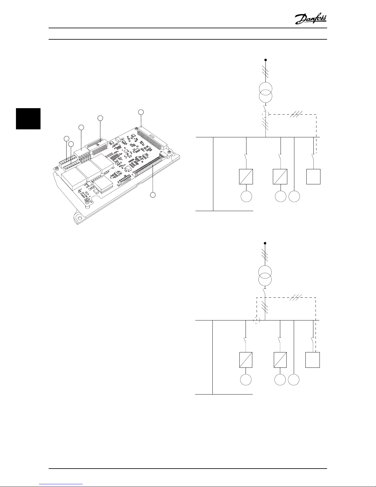
To allow for possible reuse of already present CT
transformers, the active filter allows use of either 1 A or 5
A CTs. The filter is as standard set-up for 5 A CT feedback.
If the CTs are 1 A, redirect the CT terminal plug from slot
MK101, position 1, to MK108, position 2, on the AFC card.
See Illustration 4.6.
130BB950.10
1
3
4
5
6
2
Illustration 4.6 AFC Card
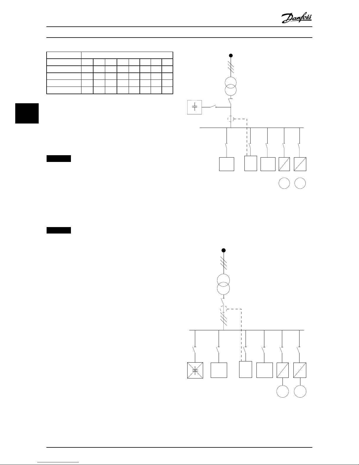
Individual or group compensation
The compensation of the filter depends on the signal that
is returned from the current transformers. The point of
installation for these sensors is to determine the loads that
are corrected.
Illustration 4.7 shows current transformers installed in front
of the entire installation with the filter compensating all
loads on the transformer. Illustration 4.8 shows current
transformers installed in front of distribution bus 2 and 1
frequency converter, so the filter only compensates for
those.
M M
M
PCC1
PCC2
130BB511.11
AAF
Illustration 4.7 CT on PCC Side
M
M
M
PCC1
PCC2
130BB512.10
AAF
Illustration 4.8 CT on Load Side
If the CTs are installed on the secondary side of the
transformer and so in front of the entire load, the filter
compensates all loads simultaneously. See Illustration 4.7.
Electrical Installation
Operating Instructions
20 Danfoss A/S © 09/2014 All rights reserved. MG90V302
44
Page 24
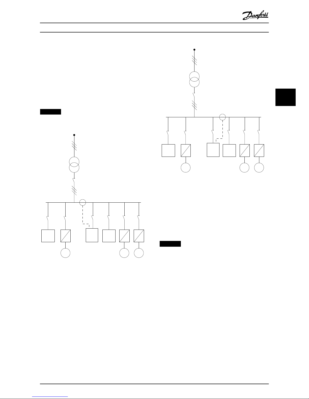
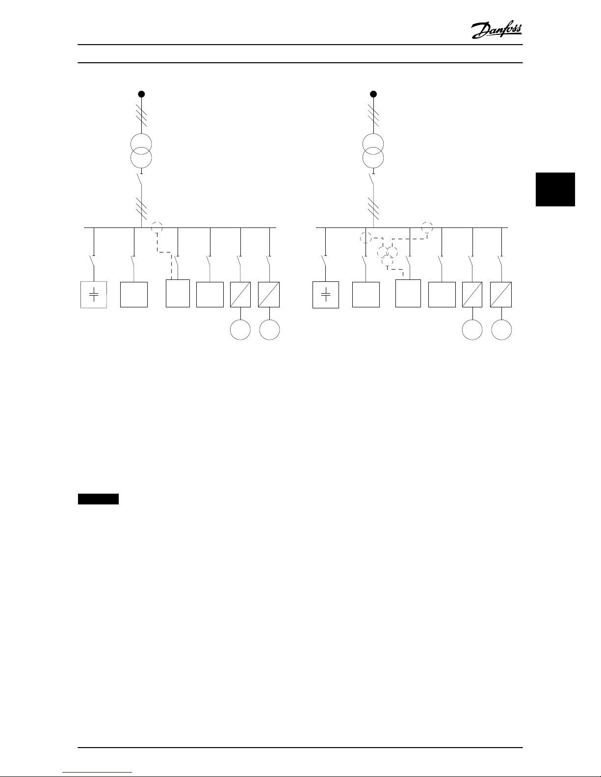
If, as in Illustration 4.8, the CTs are installed in front of only
some of the loads, the filter does not compensate
unwanted current deformation of the frequency converter
and motor on the right hand side. If CTs are installed in
front of a single load, the filter only compensates the 1
load and so form individual load compensation.
CTs can be installed on the source side (PCC–point of
common coupling), or on the load side via
parameter 300-26 CT Placement
NOTICE
The default setting is PCC side installation
PCC1
AAF
M
M
M
130BB513.11
Illustration 4.9 Current Transformers Installed on Source (PCC)
Side for Group Compensation
PCC1
AAF
M
M M
130BB514.11
Illustration 4.10 Current Transformers Installed on Load Side
for Group Compensation
If the current transformers are installed on the source
(PCC) side, the filter expects a sinusoidal (corrected) signal
feedback from the 3 sensors. If the sensors are installed on
the load side, the received signal is subtracted from the
ideal sine wave to calculate the necessary corrected
current.
NOTICE
Erratic filter operation can be a result of incorrect current
transformers connection point programming
parameter 300-26 CT Placement.
Electrical Installation Operating Instructions
MG90V302 Danfoss A/S © 09/2014 All rights reserved. 21
4 4
Page 25
4.2.8 Auto CT Detection
The active filter performs an auto detection of the installed CT. The CT auto detection can be conducted both while the
system is running and when there is no load. The filter injects a prefixed current of known amplitude and phase angle and
measures the returned CT input. The performance is conducted on each phase individually for several frequencies to check
that phase sequence and RMS are set correctly.
The Auto CT detection is pending on the following conditions:
•
Active filter bigger than 10% of CT RMS rate.
•
CTs installed on source (PCC) side (auto CT not possible for load side CT installation).
•
Only one CT per phase (not possible for summation CTs).
•
CTs are part of below standard range:
600 750
1000 1250 1500 2000 2500 3000 3500 4000
Table 4.8 Primary Rating [A]
Most restrictions on the CTs come from the installation, such as required cable length, temperature conditions, square
section of conductors, standard or split core layout, etc. A broad range of different current transformers can be used
independently of brand and type.
For specific CT requirements contact the local supplier or go to www.deif.com/
Secondary Primary Accuracy Burden Type Description
5 or 1A 30–7500A 0.2–0.5-1 1.0–45 V A ASR
ASK
EASR
EASK
Measuring current transformer for cables and bus bars
5 or 1A 100–5000A 0.5–1 1.25–30 V A KBU Split core current transformer
5 or 1A 5 or 1A 0.5–1 15–30 V A KSU/SUSK Summation current transformer
Table 4.9 Standard CT Range from Deif: Fits Most Applications
Electrical Installation Operating Instructions
22 Danfoss A/S © 09/2014 All rights reserved. MG90V302
44
Page 26
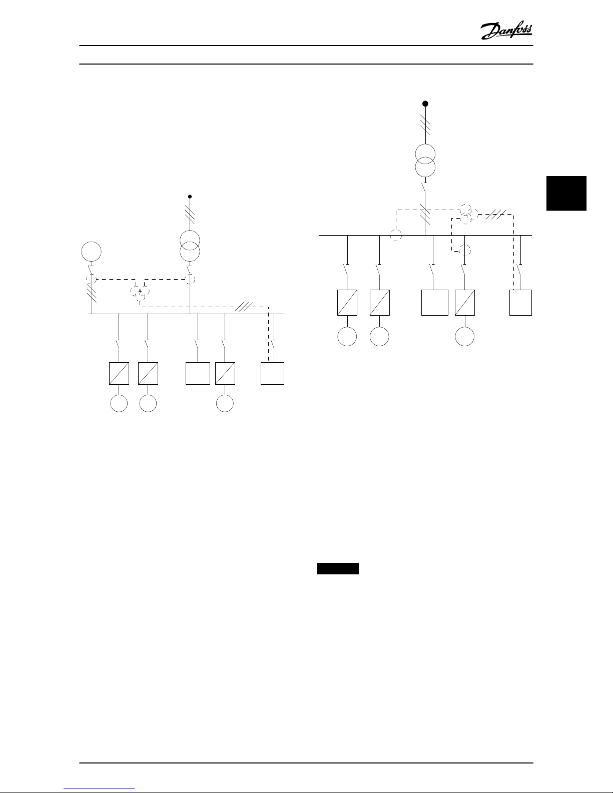
4.2.9 Summation Transformers
Multiple current sources
Summation CTs are needed when the filter is to
compensate current from several sources. This is often the
case if a filter is installed in systems with generator backup or where the filter is only to compensate a limited
number of loads, for example, marine installations.
M M
M
PCC1
130BB515.11
AAF
G
Illustration 4.11 Summation CTs on Generator Back-up
Applications (PCC-side)
M
M
M
AAF
PCC1
130BB516.11
Illustration 4.12 Summation CTs Example for Individual
Harmonic Compensation (Load Side)
Summation current transformers are available with
multiple (2–5) inputs and a common output. For
applications where summations CTs are used to add
current from several sources, make sure that all CTs
connected to the summation are from the same
manufacturer and that the following aspects are the same:
•
Polarity.
•
Primary rating.
•
RMS value.
•
Accuracy (class 0.5).
•
Location (PCC or load-side).
•
Phase sequence.
NOTICE
Use summation CTs with great caution and always
ensure correct phase sequence, current direction,
primary and secondary rating. Incorrect installation
causes problems with filter operation.
The current transformers burden calculation includes all
wires in the installation and must be conducted for the
longest total wire string when using summation CTs.
Electrical Installation
Operating Instructions
MG90V302 Danfoss A/S © 09/2014 All rights reserved. 23
4 4
Page 27
Total current [A] Maximum individual harmonic compensation
I5 I7 I11 I13 I17 I19 I23 I25
190 133 95 61 53 38 34 30 27
250 175 125 80 70 50 45 40 35
310 217 155 99 87 62 56 50 43
400 280 200 128 112 80 72 64 56
Table 4.10 Maximum Individual Harmonic Compensation
4.2.10 Operating with Capacitor Banks
The active filter is able to run with capacitor banks as long
as the resonance frequency of the capacitor bank is not in
the operation range of the active filter.
NOTICE
Always use de-tuned capacitor banks in installations with
frequency converters and active filters to avoid
resonance phenomena, unintended tripping or
component breakdown.
For de-tuned capacitors, the resonance frequency
capacitors should be tuned for an inter-harmonic number
lower than the 3rd harmonic.
NOTICE
If installed with capacitor banks of any kind, the active
filter must operate in selective compensation mode.
The capacitor bank should be installed upstream of the
filter toward the transformer. If this is not possible, install
the current transformers such that they do not measure
both needed current compensation and the capacitor
corrected current.
PCC1
M
M
AAF
130BB517.11
Illustration 4.13 Capacitor bank mounted upstream. CTs do
not measure capacitor current.
Illustration 4.13 shows recommended installation of the
active filter and CT placement in installations containing
capacitor banks.
PCC1
130BB518.11
M
M
AAF
Illustration 4.14 Incorrect Installation
Electrical Installation Operating Instructions
24 Danfoss A/S © 09/2014 All rights reserved. MG90V302
44
Page 28
PCC1
130BB519.11
M
M
AAF
Illustration 4.15 CTs Do Not Measure Capacitor Current
For installations where the CT connection point can be
moved, the configuration shown in Illustration 4.15 is also
possible. In some retrofit applications, summation CTs are
needed to ensure that the capacitor current is not
measured.
Summation CTs can also be used to subtract 2 signals from
each other and so subtract the capacitor bank corrected
current from the total current.
NOTICE
Use summation CTs with an accuracy of 0.5% of better.
PCC1
130BB520.11
M
M
AAF
Illustration 4.16 Capacitor Bank Mounted on PCC with CTs
Ensuring that Capacitor Corrected Current is not Measured.
Electrical Installation Operating Instructions
MG90V302 Danfoss A/S © 09/2014 All rights reserved. 25
4 4
Page 29
4.2.11 Fuses
Branch circuit protection
To protect the installation against electrical and fire hazard,
all branch circuits in an installation, switch gear, machines
etc., must be short-circuited and overcurrent protected
according to national/international regulations.
Short circuit protection
Protect the active filter against short circuit to avoid
electrical or fire hazard. Danfoss recommends using the
fuses in Table 4.11 and Table 4.12 to protect service
personnel and equipment in case of an internal failure in
the device.
Overcurrent protection
The active filter is equipped with an internal overcurrent
protection that avoids overload in normal running
conditions. Overload protection is needed in case of
internal failures to avoid fire hazard due to overheating of
the cables in the installation. Use fuses or circuit breakers
for overcurrent protection and comply with local and
national regulations.
Mains fuses
Active Filter Bussmann Rating
AAF006, 190 A 170M3018 350 A, 700 V
AAF006, 250 A 170M4017 700 A, 700 V
AAF006, 310 A 170M4017 700 A, 700 V
AAF006, 400 A 170M6013 900 A, 700 V
Table 4.11 Recommended Mains Fuses
Supplemental fuses
Active Filter Protection Fuse Rating
AAF006, 190–
400A SMPS
Bussmann
KTK-4 4 A, 600 V
AAF006, 190–
400A Fan
Littelfuse
KTK-15
15 A, 600
V
AAF006, 190–
400A
Soft-charge
resistor
Bussmann FNQ-
R 1 A, 600 V
AAF006, 190–
400A CT
Bussmann FNQ-
R 3 A, 600 V
Table 4.12 Recommended Supplemental Fuses
4.2.12
Mains Disconnectors
Enclosure
size Power & voltage Type
D A190 380–480 V ABB OETL-NF200A
E A250 380–480 V ABB OETL-NF400A
E A310 380–480 V ABB OETL-NF400A
E A400 380–480 V ABB OETL-NF800A
Table 4.13 Mains Disconnect Part Numbers
4.2.13
Control and CT Cable Routing
Tie down all control wires to the designated control cable
routing. Connect the shields properly to ensure optimum
electrical immunity.
CT connection
Make connections on the terminal block below the active
filter card. Place the cable in the path inside the filter and
secure it with other control wires.
4.2.14 Control Wire Installation
All terminals to the control cables are located on the
control or AFC board.
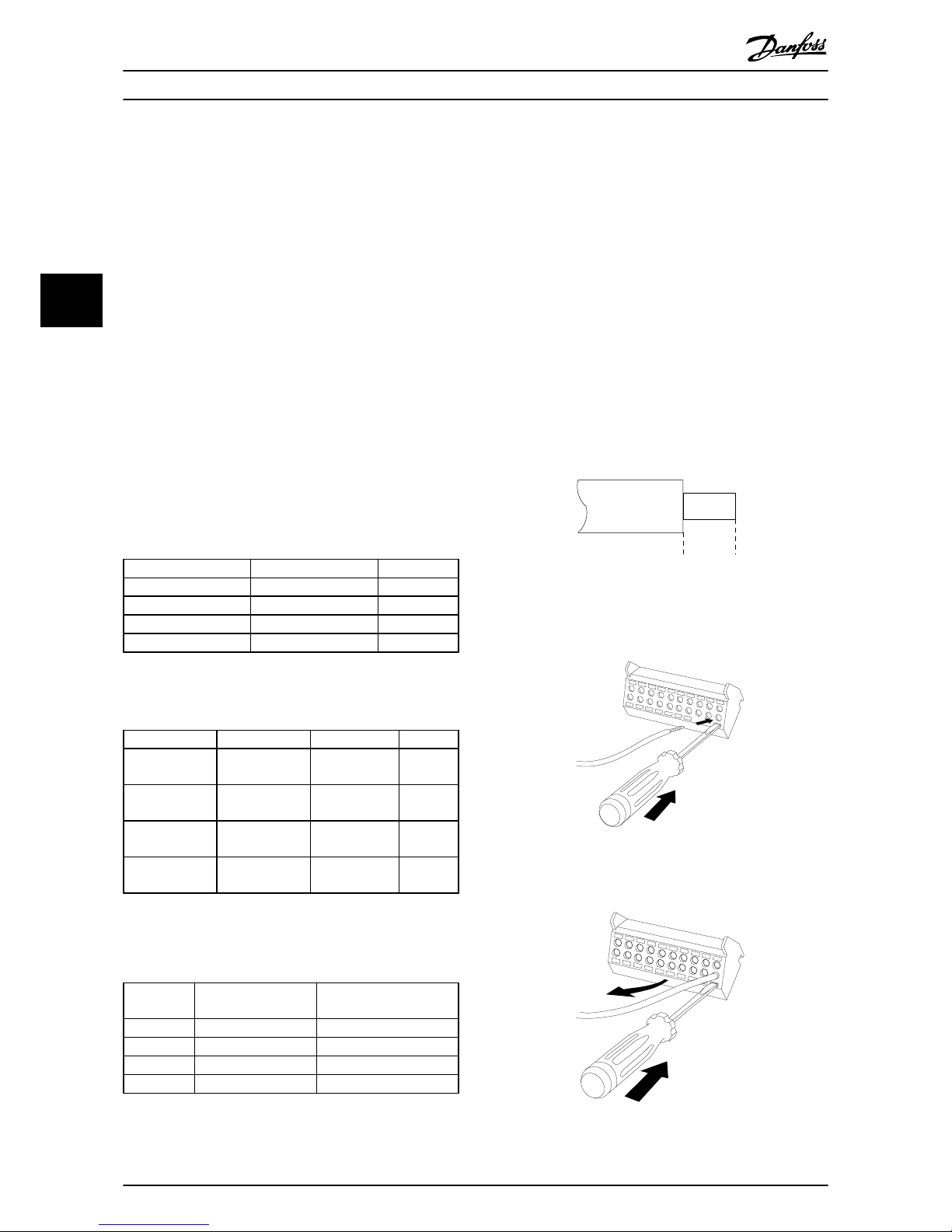
To connect the cable to the terminal:
1. Strip insulation 9–10 mm (0.4 in.)
130BA150.10
9 - 10 mm
(0.37 in)
Illustration 4.17 Stripped Insulation
2. Insert a screwdriver (maximum 0.4x2.5 mm) in the
square hole.
130BT312.10
Illustration 4.18 Inserting the Cable
3. Insert the cable in the adjacent circular hole.
130BT311.10
Illustration 4.19 Removing the Screwdriver
Electrical Installation Operating Instructions
26 Danfoss A/S © 09/2014 All rights reserved. MG90V302
44
Page 30

4. Remove the screwdriver. The cable is now
mounted in the terminal.
To remove the cable from the terminal:
1. Insert a screwdriver (maximum 0.4x2.5 mm) in the
square hole.
2. Pull out the cable.
4.2.15 Unscreened Control Wires
CAUTION
INDUCED VOLTAGE
Run input power and control wiring in separate metallic
conduits or raceways for high-frequency noise isolation.
Failure to isolate power and control wiring could result
in less than optimum controls and associated equipment
performance.
Isolate control wiring, including CT wires, from the highvoltage power wiring. When screened/armoured cable is
not used, ensure that control wires are twisted pairs and
keep the maximum possible distance between mains wire
and control cables.
Long control cables and analog signals may result in 50/60
Hz ground loops due to noise from mains supply cables.
If ground loops occur, break the screen or insert a 100 nF
capacitor between screen and chassis, if needed.
12 13 18 19 27 29 32 33 20 37
+24 VDC
0 VDC
130BT106.10
PNP (Source)
Digital input wiring
Illustration 4.20 Input Polarity of Control Terminals, PNP
NPN (Sink)
Digital input wiring
12 13 18 19 27 29 32 33 20 37
+24 VDC
0 VDC
130BT107.11
Illustration 4.21 Input Polarity of Control Terminals, NPN
NOTICE
To comply with EMC emission specifications, use
screened/armoured cables. If using unscreened control
cables, use ferrite cores to improve EMC performance.
Connect the shields in a proper way to ensure optimum
electrical immunity.
130BT340.10
Illustration 4.22 Connecting Shielded Control Cables
Electrical Installation Operating Instructions
MG90V302 Danfoss A/S © 09/2014 All rights reserved. 27
4 4
Page 31

4.2.16 Electrical Installation, Control Cables
Switch Mode
Power Supply
Analog Output
Interface
relay1
relay2
(PNP) = Source
(NPN) = Sink
ON=Terminated
OFF=Open
50 (+10 V OUT)
53 (A IN)
54 (A IN)
55 (COM A IN)
0/4-20 mA
12 (+24V OUT)
13 (+24V OUT)
18 (D IN)
20 (COM D IN)
10Vdc
15mA 130/200mA
+ - + -
(COM A OUT) 39
(A OUT) 42
(P RS-485) 68
(N RS-485) 69
(COM RS-485) 61
0V
5V
S801
0/4-20 mA
RS-485
RS-485
03
+10Vdc
-10Vdc -
+10Vdc
+10Vdc
0/4-20 mA
-10Vdc -
240Vac, 2A
24Vdc
02
01
05
04
06
240Vac, 2A
24V (NPN)
0V (PNP)
0V (PNP)
24V (NPN)
19 (D IN)
24V (NPN)
0V (PNP)
27
24V
0V
(D IN/OUT)
0V (PNP)
24V (NPN)
(D IN/OUT)
0V
24V
29
24V (NPN)
0V (PNP)
0V (PNP)
24V (NPN)
33 (D IN)
32 (D IN)
1 2
ON
S201
ON
21
S202
ON/I=0-20mA
OFF/U=0-10V
400Vac, 2A
P 5-00
21
ON
S801
*
Optional
RFI
Optional
Fuses
Optional
Manual
Disconnect
HI Reactor
L
m
L
m
L
m
L
ac
L
ac
L
ac
AC
Contactor
Relay 12
Control & AUX
Feedback
Relay 12
Control & AUX
Feedback
Soft-Charge
Converter
Side Filter
Power Stage
AF Current
Sensors
Capacitor
Current Sensors
3
3
NC
Relay
L
c
L
c
L
c
CefCefC
ef
RefRefR
ef
I
r
I
s
I
t
91 (L1)
92 (L2)
93 (L3)
130BC642.10
Illustration 4.23 Terminal Diagram
Electrical Installation
Operating Instructions
28 Danfoss A/S © 09/2014 All rights reserved. MG90V302
44
Page 32

4.3 Installation Checklist
Before completing installation of the unit, inspect the entire installation as detailed in Table 4.14. Check and mark the items
when completed.
Inspect for Description
☑
Auxiliary equipment•Ensure that all auxiliary equipment, such as switches, disconnects, or input fuses/circuit breakers are ready
for operation.
•
Check function and installation of any sensors used for feedback to the active filter.
Cable routing
•
Ensure that power wiring and control wiring are separated, screened, or in 3 separate metallic conduits for
high-frequency interference isolation.
Control wiring
•
Check for broken or damaged wires and loose connections.
•
Check that control wiring is isolated from power wiring for noise immunity.
•
Check the voltage source of the signals, if necessary.
•
The use of shielded cable or twisted pair is recommended. Ensure that the shield is terminated correctly.
Cooling clearance
•
Measure that top and bottom clearance is adequate to ensure proper air flow for cooling, see
chapter 3.2.4 Cooling and Airflow .
Ambient conditions•Check that requirements for ambient conditions are met.
Fusing and circuit
breakers
•
Check for proper fusing or circuit breakers.
•
Check that all fuses are inserted firmly and are in operational condition and that all circuit breakers are in
the open position.
Grounding
•
Check for good ground connections that are tight and free of oxidation.
•
Grounding to conduit, or mounting the back panel to a metal surface, is not a suitable grounding.
Input and output
power wiring
•
Check for loose connections.
•
Check that motor and mains are in separate conduit or separated screened cables.
Panel interior
•
Inspect that the unit interior is free of dirt, metal chips, moisture, and corrosion.
•
Check that the unit is mounted on an unpainted, metal surface.
Switches
•
Ensure that all switch and disconnect settings are in the proper positions.
Vibration
•
Check that the unit is mounted solidly, or that shock mounts are used, as necessary.
•
Check for an unusual amount of vibration.
Table 4.14 Installation Check List
CAUTION
POTENTIAL HAZARD IN THE EVENT OF INTERNAL FAILURE
Risk of personal injury when the active filter is not properly closed.
•
Before applying power, ensure all safety covers are in place and securely fastened.
Electrical Installation Operating Instructions
MG90V302 Danfoss A/S © 09/2014 All rights reserved. 29
4 4
Page 33

5 User Interface
5.1 Local Control Panel Operation
5.1.1 Modes of Operation
There are 2 ways to operate the unit:
•
Graphical Local Control Panel (GLCP)
•
RS485 serial communication or USB, both for PC
connection
5.1.2 How to Operate Graphical LCP (GLCP)
NOTICE
The active filter should be in Auto mode. Press [Auto On]
on the filter LCP.
Graphical display:
The LCD display is backlit with a total of 6 alpha-numeric
lines. All data is displayed on the LCP, which can show up
to 5 operating variables while in Status mode.
Illustration 5.1 shows an example of the frequency
converter LCP. The filter LCP looks identical but displays
information related to the filter operation.
1. Display:
1a
Status line: Status messages displaying
icons and graphics.
1b
Line 1–2: Operator data lines displaying
data and variables the user defines. Add
an extra line by pressing the [Status]
key.
1c
Status line: Status messages displaying
text.
2. Menu soft keys.
3. Indicator lights/navigation panel.
4. Operational keys.
Auto
on
Reset
Hand
on
O
Status
Quick
Menu
Main
Menu
Alarm
Log
Back
Cancel
Info
OK
Status
1(0)
1234rpm 10,4A 43,5Hz
Run OK
43,5Hz
On
Alarm
Warn.
130BA018.13
1
2
3
4
b
a
c
Illustration 5.1 Example LCP
The display is divided into 3 sections:
Top section (a)
Shows the status when in status mode or up to 2 variables
when not in status mode and in the case of alarm/
warning.
The number of the active set-up (selected as the active
set-up in parameter 0-10 Active Set-up) is shown. When
programming in another set-up than the active set-up, the
number of the set-up being programmed appears to the
right in brackets.
Middle section (b)
Shows up to 5 variables with related unit, regardless of
status. In case of alarm/warning, the warning is shown
instead of the variables.
It is possible to toggle among 3 status readout displays by
pressing [Status].
User Interface
Operating Instructions
30 Danfoss A/S © 09/2014 All rights reserved. MG90V302
55
Page 34

Operating variables with different formatting are shown on
each status screen.
Several values or measurements can be linked to each of
the displayed operating variables. Define the values/
measurements to be displayed via parameters 0-20, 0-21,
0-22, 0-23, and 0-24.
Each value/measurement readout parameter selected in
parameters 0-20 to 0-24 has its own scale and number of
digits after a possible decimal point. Larger numeric values
are displayed with few digits after the decimal point.
Example: Current readout
5.25 A; 15.2 A 105 A.
Status display I
This readout state is standard after start-up or initialisation.
Press [Info] to obtain information about the
value/ measurement linked to the displayed operating
variables (1.1, 1.2, 1.3, 2, and 3).
See the operating variables shown in the display in
Illustration 5.2. 1.1, 1.2 and 1.3 are shown in small size. 2
and 3 are shown in medium size.
1.1
2
3
1.3
1.2
130BP041.10
799 RPM
Auto Remote Ramping
1 (1)
36.4 kw7.83 A
0.000
53.2 %
Status
Illustration 5.2 Status Display I - Operating Variables
Status display II
See the operating variables (1.1, 1.2, 1.3, and 2) shown in
the display in Illustration 5.3.
In the example, speed, motor current, motor power, and
frequency are selected as variables in the first and second
lines.
1.1, 1.2 and 1.3 are shown in small size. 2 is shown in large
size.
1.1
1.2
2
1.3
130BP062.10
207RPM
Auto Remote Running
1 (1)
24.4 kW5.25A
6.9
Hz
Status
Illustration 5.3 Status Display II - Operating Variables
Bottom section
The bottom section always shows the state of the
frequency converter in Status mode.
Top section
Middle section
Bottom section
Status
43 RPM
1.4 Hz
Auto Remote Running
! Pwr.card temp (W29)
2.9%
5.44 A 25.3kW
1(1)
130BP074.10
!
Illustration 5.4 Bottom Section Status Mode
Display contrast adjustment
Press [status] and [▲] for darker display
Press [Status] and [▼] for brighter display
Indicator lights (LEDs):
If certain threshold values are exceeded, the alarm and/or
warning indicator lights are illuminated. A status and alarm
text appear on the control panel.
The On indicator light is activated when the active filter
receives power from:
•
Mains voltage.
•
A 24 V external supply.
Indicator lights (LEDs)
•
Green LED/On: Control section is working.
•
Yellow LED/Warn: Indicates a warning.
•
Flashing Red LED/Alarm: Indicates an alarm.
On
Warn.
Alarm
130BP044.10
Illustration 5.5 LED Status Indicator Lights
LCP keys
Menu keys
The menu keys are divided into functions. The keys below
the display and indicator lights are used for parameter setup, including option of display indication during normal
operation.
130BP045.10
Status
Quick
Menu
Main
Menu
Alarm
Log
Illustration 5.6 Menu Keys
User Interface Operating Instructions
MG90V302 Danfoss A/S © 09/2014 All rights reserved. 31
5 5
Page 35

[Status]
Indicates the status of the active filter. Use [Status] for
selecting display mode or reverting to display mode from:
•
Quick menu.
•
Main menu.
•
Alarm mode.
Press the [Status] key to toggle single or double readout
mode.
[Quick Menu]
The quick menu allows quick set-up of the frequency
converter or the filter and programming of the most
common functions.
The [Quick Menu] consists of:
•
Q1: My personal menu.
•
Q2: Quick set-up.
•
Q5: Changes made.
•
Q6: Loggings.
The active filter LCP displays information about operation
such as THD of current, corrected current, injected current
or Cos ϕ, and true power factor.
The Quick Menu parameters can be accessed immediately
unless a password has been created via parameters 0-60,
0-61, 0-65 or 0-66.
It is possible to switch directly between Quick Menu mode
and Main Menu mode.
[Main Menu]
The main menu is used for programming all parameters.
The Main Menu parameters can be accessed immediately
unless a password has been created via parameters 0-60,
0-61, 0-65 or 0-66.
It is possible to switch directly between Main Menu mode
and Quick Menu mode.
A parameter shortcut can be carried out by pressing down
[Main Menu] for 3 s. The parameter shortcut allows direct
access to any parameter.
[Alarm Log]
The alarm log displays an alarm list of the 5 latest alarms
(numbered A1-A5). To obtain more details about an alarm,
press the navigation keys to navigate to the alarm number
and press [OK]. Information is displayed about the
condition of the frequency converter or filter before it
enters the alarm mode.
[Back]
The back key reverts to the previous step or layer in the
navigation structure.
B
a
c
k
Illustration 5.7 Back Key
[Cancel]
The last change or command is cancelled as long as the
display has not been changed.
C
a
n
c
e
l
Illustration 5.8 Cancel Key
[Info]
The info key displays information about a command,
parameter, or function in any display window. [Info]
provides detailed information when needed.
Exit Info mode by pressing either [Info], [Back], or [Cancel].
I
n
f
o
Illustration 5.9 Info Key
Navigation keys
The 4 navigation keys are used to navigate between the
options available in [Quick Menu], [Main Menu], and [Alarm
Log]. Move the cursor with the navigation keys.
[OK]
The OK key is used for selecting a parameter marked by
the cursor and for enabling the change of a parameter.
130BT117.10
OK
Back
Info
Warn
Alarm
On
Cancel
Illustration 5.10 Navigation Keys
Operation keys
For local control. Found at the bottom of the control
panel.
130BP046.10
Hand
on
O
Auto
on
Reset
Illustration 5.11 Operation Keys
User Interface Operating Instructions
32 Danfoss A/S © 09/2014 All rights reserved. MG90V302
55
Page 36

[Hand On]
Press [Hand On] to begin operation of the active filter via
the LCP. The key can be [1] Enabled or [0] Disabled via
0-40 [Hand on] Key on LCP.
The following control signals are active when [Hand On]
is pressed:
•
[Hand On] - [Off] - [Auto On].
•
Reset.
•
Stop inverse.
•
Set-up select bit 0; Set-up select bit 1.
NOTICE
External stop signals activated with control signals or a
serial bus overrides a Start command via the LCP.
[Off]
The OFF key stops the active filter (when pressed on the
filter LCP). The key can be [1] Enabled or [0] Disabled via
parameter 0-41 [Off] Key on LCP. If no external stop function
is selected, and the [Off] key is inactive, the active filter
can only be stopped by disconnecting the mains supply.
[Auto On]
The Auto On key enables the active filter to be controlled
via the control terminals and/or serial communication.
When a start signal is applied on the control terminals
and/or the bus, the active filter starts. The key can be [1]
Enabled or [0] Disabled via parameter 0-42 [Auto on] Key on
LCP.
NOTICE
An active HAND-OFF-AUTO signal via the digital inputs
has higher priority than the control keys [Hand On] –
[Auto On].
[Reset]
The Reset key is used for resetting the filter after an alarm
(trip). The key can be [1] Enabled or [0] Disabled via
parameter 0-43 [Reset] Key on LCP on the LCP.
Parameter shortcut
A parameter shortcut can be carried out by holding down
[Main Menu] for 3 s. The parameter shortcut allows direct
access to any parameter.
5.1.3
Changing Data
1. Press [Quick Menu] or [Main Menu].
2.
Press [▲] and [▼] to find the parameter group to
edit.
3. Press [OK].
4.
Press [▲] and [▼] to find the parameter to edit.
5. Press [OK].
6.
Press [▲] and [▼] to select the correct parameter
setting. Or, to move to digits within a number,
use [◄] and [►]. The cursor indicates the digit
selected to change. [▲] increases the value, [▼]
decreases the value.
7. Press [Cancel] to ignore the change, or press [OK]
to accept the change and enter a new setting.
5.1.4 Changing a Text Value
If the selected parameter is a text value, change the text
value by pressing the [▲]/[▼] keys.
[▲] increases the value, and [▼] decreases the value. Place
the cursor on the value to be saved and press [OK].
5.1.5
Changing a Group of Numeric Data
Values
If the selected parameter represents a numeric data value,
change the selected data value by pressing the [◄] and [►]
navigation keys as well as [▲] and [▼] keys. Press [◄] and
[►] to move the cursor horizontally.
Press [▲]/[▼] to change the data value. [▲] increases the
data value, and [▼] decreases the data value. Place the
cursor on the value to be saved and press [OK].
5.1.6
Changing of Data Value, Step-by-Step
Certain parameters can be changed step-by-step or
infinitely variably. This method applies to
parameter 300-10 Active Filter Nominal Voltage.
The parameters are changed both as a group of numeric
data values and as numeric data values infinitely variably.
5.1.7
Readout and Programming of
Indexed Parameters
Parameters are indexed when placed in a rolling stack.
15-30 Alarm Log: Error Code to parameter 15-32 Alarm Log:
Time contain a fault log that can be read out. Select a
parameter, press [OK], and use [▲]/[▼] to scroll through the
value log.
Use 3-10 Preset Reference as another example:
Select the parameter, press [OK], and press [▲]/[▼] to scroll
through the indexed values. To change the parameter
value, select the indexed value and press [OK]. Change the
value by using [▲]/[▼]. Press [OK] to accept the new
setting. Press [Cancel] to abort. Press [Back] to leave the
parameter.
User Interface
Operating Instructions
MG90V302 Danfoss A/S © 09/2014 All rights reserved. 33
5 5
Page 37

5.1.8 Quick Transfer of Parameter Settings
with the LCP
Once the set-up is complete, store (back up) the parameter
settings in the LCP or on a PC via MCT 10 set-up software
tool.
WARNING
Running the unit during these operations can cause
unexpected operation. Stop the unit before performing
any of these operations. Failure to do so can cause
damage or injury..
Data storage in LCP
1.
Go to 0-50 LCP Copy.
2. Press [OK].
3.
Select [1] All to LCP.
4. Press [OK].
All parameter settings are now stored in the LCP indicated
by the progress bar. When 100% is reached, press [OK].
The LCP can now be connected to another active filter and
the parameter settings copied to this active filter.
Data transfer from LCP to the unit
1.
Go to 0-50 LCP Copy.
2. Press [OK].
3.
Select [2] All from LCP.
4. Press [OK].
The parameter settings stored in the LCP are now
transferred to the active filter indicated by the progress
bar. When 100% is reached, press [OK].
5.1.9
Initialisation to Default Settings
There are 2 ways to initialise the unit to default:
Recommended initialisation and manual initialisation.
Each method has a different impact.
5.1.9.1
Recommended Initialisation Method
Initialisation via 14-22 Operation Mode
1.
Select 14-22 Operation Mode.
2. Press [OK].
3.
Select Initialisation.
4. Press [OK].
5. Remove power to the unit and wait for the
display to turn off.
6. Reconnect power to reset the unit.
7. Press [Reset].
14-22 Operation Mode
initialises all except:
•
Parameter 14-50 RFI Filter.
•
8-31 Address.
•
8-32 Baud Rate
•
8-35 Minimum Response Delay
•
Parameter 8-36 Max Response Delay
•
8-37 Maximum Inter-Char Delay
•
Parameter 15-00 Operating hours to
parameter 15-05 Over Volt's
•
Parameter 15-20 Historic Log: Event to
parameter 15-22 Historic Log: Time
•
15-30 Alarm Log: Error Code to
parameter 15-32 Alarm Log: Time
NOTICE
Parameters selected in 0-25 My Personal Menu, stay
present with default factory setting.
5.1.9.2 Manual Initialisation Method
NOTICE
When carrying out manual initialisation, serial communication, RFI filter settings, and fault log settings are reset.
Manual initialisation removes parameters selected in
0-25 My Personal Menu.
1. Disconnect from mains and wait until the display
turns off.
2. Press [Status] - [Main Menu] - [OK] at the same
time during power-up for graphical LCP .
3. Release the keys after 5 s.
4. The unit is now programmed according to default
settings.
This parameter initialises all except:
•
Parameter 15-00 Operating hours
•
Parameter 15-03 Power Up's
•
Parameter 15-04 Over Temp's
•
Parameter 15-05 Over Volt's
User Interface
Operating Instructions
34 Danfoss A/S © 09/2014 All rights reserved. MG90V302
55
Page 38

5.1.10 RS485 Bus Connection
A frequency converter or active filter can be connected to
a controller (or master) together with other loads using the
RS485 standard interface. Terminal 68 is connected to the
P signal (TX+, RX+), while terminal 69 is connected to the
N signal (TX-, RX-).
To avoid potential equalising currents in the screen,
ground the cable screen via terminal 61, which is
connected to the frame via an RC-link.
Bus termination
Terminate the RS485 bus via a resistor network at both
ends. If the unit is the first or the last device in the RS485
loop, set the switch S801 on the control card to ON.
5.1.11
Connection to a PC
To program the unit from a PC, install the PC-based
configuration tool MCT 10 Set-up Software.
The PC is connected via a standard (host/device) USB cable
to the unit, or via the RS485 interface.
NOTICE
The USB connection is galvanically isolated from the
supply voltage (PELV) and other high-voltage terminals.
The USB connection is connected to protective ground
on the unit. Use only an isolated laptop as PC
connection to the USB connector.
For control cable connections, see chapter 4.2.16 Electrical
Installation, Control Cables.
130BT308.10
Illustration 5.12 Control Cable Connections
User Interface Operating Instructions
MG90V302 Danfoss A/S © 09/2014 All rights reserved. 35
5 5
Page 39

6 Applications and Basic Programming
6.1 Paralleling of Active Filters
6.1.1 Parameter Set-up
The factory settings for the active filter are selected for
optimal operation for most applications with a minimum
of programming needed. The filter is set in overall
harmonic compensation mode with harmonic current
priority. Selection of readouts and information to be
displayed on the LCP status lines can be customised. In a
few cases, the filter must be tuned specially for the given
grid and load conditions.
The following steps are often sufficient to set up the filter
and get proper operation:
•
Program the external CTs:
-
Check that the CT location is correct in
parameter 300-26 CT Placement.
-
Activate the Auto CT Detection in
parameter 300-29 Start Auto CT Detection.
-
Confirm the found CT ratio, polarity, and
sequence.
•
Make sure that the filter is in auto mode (press
[Auto On] on the LCP).
All digital input/output terminals are multifunctional. All
terminals have factory default functions suitable for most
applications but if other special functions are required,
they must be programmed in parameter group 5-**Digital
I/O Mode.
6.1.2
Paralleling of Active Filters
The VLT® Active Filter is designed for installation in
networks with other active infeed current suppliers and so
operate in conjunction with other active filters, UPS’s and
AFE drives. There is no limitation to the allowable number
of units. Four filters can be connected to the same CT
input and run in a master/slave configuration. The master
unit activates the individual slaves according to mitigation
demand in a cascade network. This keeps the switching
losses as low as possible and so improves the system
efficiency. The master unit automatically allocates a new
slave in case a unit is out due to service or has unintentionally tripped.
6.1.3
CT-wiring for Parallel Filter
Connection
VLT active filter is designed to allow up to 4 units to run in
parallel for a harmonic and reactive compensation
extension to 4 times the individual filter rating. The parallel
installed filters use the same current input and so only one
external set of CTs have to be installed. In case additional
filtration is needed, additional filters have to use separate
current transformers installed up or down stream of the CT
signal and injection point of the paralleled installation.
PCC1
130BB713.10
AAF
AAF
AAF
AAF
Illustration 6.1 2 Sets of AAFs in Master/Slave
Applications and Basic Prog... Operating Instructions
36 Danfoss A/S © 09/2014 All rights reserved. MG90V302
66
Page 40

PCC1
130BB714.10
AAF
AAF
AAF AAF
Illustration 6.2 4 AAFs in Master/Slave
The parallel connected filters must have the CT input
signal wired in serial according to Illustration 6.3:
130BB715.10
F2
F1
L1
12
12
12
M
Illustration 6.3 Single-phase CT-connection Diagram for Master
and Slave
CAUTION
Unshielded cables can lead to noise on the CT and result
in incorrect harmonic filtration. Use shielded cables for
correct EMC installation. Failure to do so can cause
improper equipment function or damage.
The current transformers VA-limitation still have to be kept
for filters in parallel, and so total wire lengths must be
limited according to wire type and CT VA-rating.
[M]=([VA]-1,25)/(25*[Ω/M])
See chapter 4.2.1 Power Connections for more details.
6.1.4
Control Wire Connection for Parallel
Filter Run
In addition to the CT wiring, all slave units must be
connected to the master via either digital or analog inputs.
Illustration 6.4 shows the necessary control wire
connections:
M
42
53
27
19
29
20
42
53
27
19
29
20
F1
42
53
27
19
29
20
F2
42
53
27
19
29
20
F3
130BB716.11
Illustration 6.4 Control Wire Connection of Slave units F1-F3 to
Master M
Table 6.1 shows the necessary connections when fewer
than 4 units are paralleled. The software set-up of digital
and analog input/output is done automatically according
to Table 6.1, based on software programming
parameter 300-40 Master Follower Selection and
parameter 300-41 Follower ID.
Terminal
connection at
follower
Terminal
connection at
master
Follower 1 (F1) 27 27
Follower 2 (F2) 27 19
Follower 3 (F3) 42 53
All (parallel) 29 29
All (parallel) 20 20
Table 6.1 Master/follower Terminal Connections
Follower units will not work if control wires are not
correctly connected. Connect control wiring as directed in
chapter 4 Electrical Installation. Failure to do so can cause
malfunction.
NOTICE
Use screened control wires for correct EMC installation.
6.1.5 Software Set-up of Parallel Filter Run
Running followers in different mitigation mode or with
changed priorities individually compromises performance.
Parallel-connected filters are thus always to be
programmed with same compensation and priority mode.
Ensure all CT settings have been set identically in all
parallel connection units, and all have the same hardware
secondary CT configuration.
Applications and Basic Prog...
Operating Instructions
MG90V302 Danfoss A/S © 09/2014 All rights reserved. 37
6 6
Page 41

The automatic CT detection is still effective for filters in a
master/follower configuration but setting follower units
manually is recommended. Use the following procedure for
setting the CT values:
1.
Program master unit parameter 300-10 Active Filter
Nominal Voltage.
2.
Program master unit parameter 300-26 CT
Placement.
3. Perform an automatic CT detection on master
unit parameter 300-29 Start Auto CT Detection.
4. Note the auto CT result and manually program
each follower unit.
5.
Ensure identical settings in
parameter 300-10 Active Filter Nominal Voltage
andparameter 300-26 CT Placement on each unit.
Alternatively, each follower unit can conduct an automatic
CT detection after the master unit is turned off. Only run 1
auto CT detection at a time.
In addition to this CT setting, it is also necessary to set
each unit to have its respective role in the cascade
network. Parameter 300-40 Master Follower Selection is set
to master or follower for each unit.
300-40 Master Follower Selection
Option: Function:
[0] Master If operating active filters in parallel, select
whether this filter is a master or a follower
active filter.
[1] Follower
[2] * Not Paralleled
NOTICE
Ensure that only 1 master is set in each group of parallel
connected filters. Verify that no other unit is set to
master.
After changing this parameter, additional parameters are
accessible. For the master units, 300-42 Number of Follower
AFs has to be programmed for the number of followers
connected.
300-41 Follower ID
Range: Function:
1* [1 - 3 ] Enter the unique ID of this follower. Verify that no
other follower uses the same ID.
NOTICE
Parameter 300-41 Follower ID is not accessible unless
parameter 300-40 Master Follower Selection is set to
follower.
NOTICE
Each follower should have its own follower ID. Verify
that no 2 followers have the same follower ID.
300-42 Num. of Follower AFs
Range: Function:
1* [1 - 3 ] Enter the total number of follower active filters.
The master active filter only controls this number
of followers.
NOTICE
Parameter 300-42 Num. of Follower AFs is not accessible
unless parameter 300-40 Master Follower Selection is set
to master.
Program each follower unit at parameter 300-41 Follower ID
with a unique ID.
Before starting the units by pushing [Auto On], check that
the following parameters all have been correctly
programmed and have similar values for all units sharing 1
set of CTs:
•
Parameter 300-00 Harmonic Cancellation Mode.
•
Parameter 300-20 CT Primary Rating.
•
300-22 CT Nominal Voltage.
•
Parameter 300-24 CT Sequence.
•
Parameter 300-25 CT Polarity.
•
Parameter 300-26 CT Placement.
•
Parameter 300-30 Compensation Points.
•
Parameter 300-35 Cosphi Reference.
6.2
Programming
6.2.1 Quick Menu Mode
The LCP provides access to all parameters listed under the
Quick Menus. Press [Quick Menu] to display the list of
options in the quick menu.
Efficient parameter set-up for most applications
The parameters for most the applications are set up via
the Quick Menu.
To set parameters through the [Quick Menu]:
1.
Select [2] Quick set-up for selecting language,
compensation mode, CT set-up, etc.
2.
Select [1] My personal menu to set up the LCP
readout parameters. If preset display is
acceptable, this operation can be left out.
It is recommended to do the set-up in the order listed.
Applications and Basic Prog...
Operating Instructions
38 Danfoss A/S © 09/2014 All rights reserved. MG90V302
66
Page 42

01 My Personal Menu
02 Quick Setup
05 Changes Made
06 Loggings
0.0% 0.00
Quick Menus
1(1)
130BB473.10
Illustration 6.5 Quick Menu View
If No Operation is selected in terminal 27, no connection to
+24 V on terminal 27 is necessary to enable start.
If Coast Inverse is selected in Terminal 27, a connection to
+24 V is necessary to enable start.
6.2.2
Q1 My Personal Menu
Parameters defined by the user can be stored in Q1 My
Personal Menu. Select My Personal Menu to display only the
parameters, which have been pre-selected and
programmed as personal parameters. A large-scale active
filter user may have pre-programmed important set-up
values in the My Personal Menu to make on-site commissioning/fine-tuning simpler. These parameters are selected
in parameter 0-25 My Personal Menu. Up to 20 different
parameters can be defined in this menu.
Q1 My Personal Menu
Parameter number and Name Factory default
0-01 Language
English
0-20 Display Line 1.1 Small
Power Factor
0-21 Display Line 1.2 Small
THD of current
0-22 Display Line 1.3 Small
Mains current
0-23 Display Line 2 Large
Output current (corrected)
0-24 Display Line 3 Large
Mains frequency
15-51 Frequency Converter Serial
Number
Table 6.2 My Personal Menu Settings
6.2.3
Q2 Quick Setup
The parameters in Q2 Quick Setup are the basic parameters
that are always needed to set up the active filter.
Q2 Quick Setup
Parameter number and
Name
Factory default
0-01 Language
English
300-22 CT Nominal Voltage
Same as AF
Parameter 300-29 Start Auto
CT Detection
Off
Parameter 300-01 Compensation Priority
Harmonics
Parameter 300-00 Harmonic
Cancellation Mode
Overall
Table 6.3 Quick Setup Settings
NOTICE
Set the nominal voltage and CT secondary rating and
change parameter 300-26 CT Placement to PCC before
starting the Auto CT detection. Auto CT detection is only
possible if CTs are located at the point of common
coupling.
6.2.4 Q5 Changes Made
Use Q5 Changes Made for fault finding.
Select Q5 Changes Made to get information about:
•
The 10 most recent changes. Use ▲ and ▼ to
scroll between the last 10 parameters changed.
•
Changes made since default setting.
6.2.5
Q6 Loggings
Use Q6 Loggings for fault finding.
Select Loggings to get information about the display line
readouts. The information is shown as graphs. Only display
parameters selected in 0-20 Display Line 1.1 Small and
0-24 Display Line 3 Large can be viewed. It is possible to
store up to 120 samples in the memory for later reference.
Note that the parameters listed in Table 6.4 for Q6 only
serve as examples as they vary depending on the
programming of the particular active filter.
Q6 Loggings
0-20 Display Line 1.1 Small
Power Factor
0-21 Display Line 1.2 Small
THD of current
0-22 Display Line 1.3 Small
Mains Current
0-23 Display Line 2 Large
Output Current
0-24 Display Line 3 Large
Mains Frequency
Table 6.4 Loggings Parameter Examples
Applications and Basic Prog...
Operating Instructions
MG90V302 Danfoss A/S © 09/2014 All rights reserved. 39
6 6
Page 43

6.2.6 Main Menu Mode
The LCP provides access to the Main Menu mode. Select
the Main Menu mode by pressing the [Main Menu] key.
The resulting readout appears on the display of the LCP.
Lines 2 through 5 on the display show a list of parameter
groups that can be selected via the ▲ and ▼ keys.
Each parameter has a name and number that remain the
same regardless of the programming mode. In the Main
Menu mode, the parameters are divided into groups. The
first digit of the parameter number (from the left) indicates
the parameter group number. All parameters can be
changed in the main menu. Option cards added to the
unit enable additional parameters associated with the
option device.
6.2.7 Parameter Selection
Select a parameter group with the navigation keys.
The following parameter groups are accessible:
Group Title Function
0-** Operation/Display Parameters related to the fundamental functions of the filter, function of the LCP
keys and configuration of the LCP display.
5-** Digital In/Out Parameter group for configuring the digital inputs and outputs.
8-** Communication and Options Parameter group for configuring communications and options.
14-** Special Functions Parameter group for configuring special filter functions.
15-** Unit Information Parameter group containing filter information such as operating data, hardware
configuration, and software versions.
16-** Data Readouts Parameter group for data readouts, e.g. actual references, voltages, control, alarm,
warning, and status words.
300-** AF Settings Parameter group for setting the active filter.
301-** AF Readouts Parameter group for the filter readouts.
Table 6.5 Parameter Groups
After selecting a parameter group, select a parameter with the navigation keys.
The middle section on the LCP display shows the parameter number and name as well as the selected parameter value.
Applications and Basic Prog... Operating Instructions
40 Danfoss A/S © 09/2014 All rights reserved. MG90V302
66
Page 44

6.3 Description of Parameters
6.3.1 Main Menu
The main menu includes all available parameters in the
VLT® Active Filter. All parameters are grouped by name
indicating the function of the parameter group. All
parameters are listed by name and number in this manual.
6.4 0-** Operation/Display
Parameters in this group are related to the fundamental
functions of the active filter, function of the LCP keys, and
configuration of the LCP display.
6.4.1
0-0* Basic Settings
0-01 Language
Option: Function:
Defines the language to be used in the
display. The filter can be delivered with 4
different language packages. English and
German are included in all packages.
English cannot be erased or manipulated.
[0] * English Part of Language packages 1 - 4
[1] Deutsch Part of Language packages 1 - 4
[2] Francais Part of Language package 1
[3] Dansk Part of Language package 1
[4] Spanish Part of Language package 1
[5] Italiano Part of Language package 1
[6] Svenska Part of Language package 1
[7] Nederlands Part of Language package 1
[10] Chinese Part of Language package 2
[20] Suomi Part of Language package 1
[22] English US Part of Language package 4
[27] Greek Part of Language package 4
[28] Bras.port Part of Language package 4
[36] Slovenian Part of Language package 3
[39] Korean Part of Language package 2
[40] Japanese Part of Language package 2
[41] Turkish Part of Language package 4
[42] Trad.Chinese Part of Language package 2
[43] Bulgarian Part of Language package 3
[44] Srpski Part of Language package 3
[45] Romanian Part of Language package 3
0-01 Language
Option: Function:
[46] Magyar Part of Language package 3
[47] Czech Part of Language package 3
[48] Polski Part of Language package 4
[49] Russian Part of Language package 3
[50] Thai Part of Language package 2
[51] Bahasa
Indonesia
Part of Language package 2
[52] Hrvatski
0-04 Operating State at Power-up (Hand)
Option: Function:
Selects the operating mode upon
reconnection of the filter to mains voltage
after power down in Hand (local) operation
mode.
[0] Resume Restarts the filter maintaining the same start/
stop settings (applied by [HAND ON/OFF]) as
before the filter was powered down.
[1] * Forced stop Restarts the filter with a saved local reference,
after mains voltage reappears and after
pressing [HAND ON].
6.4.2 0-1* Set-up Operations
Define and control the individual parameter set-ups.
The active filter has 4 parameter set-ups that can be
programmed independently of one another, making it
flexible.
The active set-up (the set-up in which the active filter is
currently operating) can be selected in
parameter 0-10 Active Set-up and is displayed on the LCP.
Using multi set-up, it is possible to switch between set-ups
with the active filter running or stopped, via digital input
or serial communication commands. If it is necessary to
change set-ups while running, ensure that
parameter 0-12 This Set-up Linked to is programmed as
required. Using parameter 0-11 Edit Set-up, it is possible to
edit parameters within any of the set-ups while continuing
the active filter operation in its active set-up, which can be
a different set-up than the one being edited.
Use parameter 0-51 Set-up Copy to copy parameter settings
between the set-ups enabling faster commissioning if
similar parameter settings are required in different set-ups.
Applications and Basic Prog...
Operating Instructions
MG90V302 Danfoss A/S © 09/2014 All rights reserved. 41
6 6
Page 45

0-10 Active Set-up
Option: Function:
Select the set-up to control the filter functions.
[0] Factory
setup
Cannot be changed. It contains the factory
data set, and can be used as a data source
when returning the other set-ups to a known
state.
[1] * Set-up 1
[1] Set-up 1to [4] Set-up 4are the 4 separate
parameter set-ups within which all parameters
can be programmed.
[2] Set-up 2
[3] Set-up 3
[4] Set-up 4
[9] Multi Set-upRemote set-up selections using digital inputs
and the serial communication port. This set-up
uses the settings from parameter 0-12 This Set-
up Linked to. Stop the filter before making
changes to open- and closed loop functions
Use parameter 0-51 Set-up Copy to copy a set-up to one or
all other set-ups. Stop the filter before switching between
set-ups where parameters marked not changeable during
operation have different values. To avoid conflicting
settings of the same parameter within 2 different set-ups,
link the set-ups together using parameter 0-12 This Set-up
Linked to. Parameters which are not changeable during
operation are marked FALSE in the parameter lists in
chapter 6.12 Parameter Lists.
0-11 Edit Set-up
Option: Function:
Select the set-up to be edited (i.e.
programmed) during operation; either the
active set-up or one of the inactive set-ups.
[0] Factory
setup
Cannot be edited but it is useful as a data
source to return the other set-ups to a known
state.
[1] * Set-up 1
[1] Set-up 1to [4] Set-up 4 can be edited freely
during operation, independently of the active
set-up.
[2] Set-up 2
[3] Set-up 3
[4] Set-up 4
[9] Active Set-upCan also be edited during operation. Edit the
selected set-up from a range of sources: LCP,
FC, RS485, FC, USB, or up to 5 Fieldbus sites.
0-12 This Set-up Linked to
Option: Function:
To enable conflict-free changes from one set-up
to another during operation, link set-ups
containing parameters that are not changeable
during operation. The link ensures synchronising of the not changeable during operation
0-12 This Set-up Linked to
Option: Function:
parameter values when moving from one setup to another during operation. Not changeable
during operation parameters can be identified
by the label FALSE in the parameter lists in
chapter 6.12 Parameter Lists.
Parameter 0-12 This Set-up Linked to is used by
[9] Multi set-up in parameter 0-10 Active Set-up.
[9] Multi set-up is used to move from one set-up
to another during operation (i.e. while the filter
is running).
Example:
Use [9] Multi set-up to shift from Set-up 1 to
Set-up 2 while the unit is running. Programme
in Set-up 1 first, then ensure that Set-up 1 and
Set-up 2 are synchronised (or linked). Synchronisation can be performed in 2 ways:
1.
Change the edit set-up to [2] Set-up
2in parameter 0-11 Edit Set-up and set
parameter 0-12 This Set-up Linked to to
[1] Set-up 1. This starts the linking
(synchronising) process.
130BP075.10
0-12 This Set-up Linked to
0 RPM
0.00A
1(1)
Set-up Handling 0-1*
[1]
Setup 1
Illustration 6.6 Synchronisation Method 1
OR
1. While still in Set-up 1, copy Set-up 1
to Set-up 2. Then set
parameter 0-12 This Set-up Linked to to
[2] Set-up 2. This starts the linking
process.
130BP076.10
0-12 This Set-up Linked to
0 RPM
0.00A
1(1)
Set-up Handling
0-1*
[2]
Setup 2
Illustration 6.7 Synchronisation Method 2
After the link is complete,
parameter 0-13 Readout: Linked Set-ups reads
{1,2} to indicate that all not changeable during
operation parameters are now the same in Setup 1 and Set-up 2. If there are changes to a not
changeable during operation parameter, in Setup 2, they are also changed automatically in
Applications and Basic Prog...
Operating Instructions
42 Danfoss A/S © 09/2014 All rights reserved. MG90V302
66
Page 46

0-12 This Set-up Linked to
Option: Function:
Set-up 1. A switch between Set-up 1 and Set-up
2 during operation is now possible.
[0] * Not linked
[1] Set-up 1
[2] Set-up 2
[3] Set-up 3
[4] Set-up 4
0-13 Readout: Linked Set-ups
Range: Function:
0* [0 -
255 ]
View a list of all the set-ups linked by means of
0-12 This Set-up Linked to. The parameter has one
index for each parameter set-up. The parameter
value displayed for each index represents which
set-ups are linked to that parameter set-up.
Index LCP value
0 {0}
1 {1,2}
2 {1,2}
3 {3}
4 {4}
Table 6.7 Example: Set-up 1 and Set-up 2 are
linked
0-14 Readout: Edit Set-ups / Channel
Range: Function:
0* [-2147483648 -
2147483647]
View the setting of parameter 0-11 Edit Set-
up for each of the 4 different
communication channels. When the
number is displayed as a hex number, as it
is in the LCP, each number represents 1
channel.
Numbers 1-4 represent a set-up number; F
means factory setting; and A means active
set-up. The channels are, from right to left:
LCP, FC bus, USB, HPFB1-5.
Example: The number AAAAAA21h means
the following:
•
The frequency converter selected
Set-up 2 via a fieldbus channel.
This selection is reflected in
parameter 0-11 Edit Set-up.
•
A user selected Set-up 1 via the
LCP.
•
All other channels are using the
active set-up.
6.4.3
0-2* LCP Display
Define the variables displayed in the LCP.
NOTICE
Refer to 0-37 Display Text 1, 0-38 Display Text 2 and
0-39 Display Text 3 for information on how to write
display texts.
0-20 Display Line 1.1 Small
Option: Function:
Select a variable for display in
line 1, left position.
[0] None No display value selected.
[1501] Running Hours Running hours meter of the
unit.
[1600] Control Word Present control word
[1603] Status Word Present status word.
[1630] DC Link Voltage Intermediate circuit voltage in
the unit.
[1634] Heatsink Temp. Present heat sink temperature
of the unit. The cut-out limit is
95 ±5 °C; cutting back in occurs
at 70 ±5 °C.
[1635] Inverter Thermal Percentage load of the inverters.
[1636] Inv. Nom. Current Nominal current of the unit.
[1637] Inv. Max. Current Maximum current of the unit.
[1639] Control Card Temp. Temperature of the control card.
[1660] Digital Input Signal states form the 6 digital
terminals (18, 19, 27, 29, 32 and
33). There are 16 bits in total,
but only 6 of them are used.
Input 18 corresponds to the
leftmost of the used bits. Signal
low=0; Signal high=1.
[1666] Digital Output [bin] Binary value of all digital
outputs.
[1671] Relay Output [bin] Binary value of the relay
outputs.
[1680] Fieldbus CTW 1 Control word (CTW) received
from the bus master.
[1684] Comm. Option STW Extended Fieldbus communi-
cation option status word.
[1685] FC Port CTW 1 Control word (CTW) received
from the bus master.
[1690] Alarm Word One or more alarms in a hex
code.
[1691] Alarm Word 2 One or more alarms in a hex
code.
[1692] Warning Word One or more warnings in a hex
code.
[1693] Warning Word 2 One or more warnings in a hex
code.
[1694] Ext. Status Word One or more status conditions
in a hex code.
Applications and Basic Prog... Operating Instructions
MG90V302 Danfoss A/S © 09/2014 All rights reserved. 43
6 6
Page 47

0-20 Display Line 1.1 Small
Option: Function:
[30100] Output Current [A]
[30101] Output Current [%]
[30102] Fifth Output Current
[A]
[30103] Seventh Output
Current [A]
[30104] Eleventh Output
Current [A]
[30105] Thirteenth Output
Current [A]
[30106] Seventeenth Output
Current [A]
[30107] Nineteenth Output
Current [A]
[30108] Twenty-third Output
Current [A]
[30109] Twenty-fifth Output
Current [A]
[30110] THD of current [%]
[30112] Power factor
[30113] Cosphi
[30114] Leftover Currents
[30120] Mains Current [A]
[30121] Mains Frequency
[30122] Fund. Mains Current
[A]
0-21 Display Line 1.2 Small
Option: Function:
[0] * None Select a variable for display in line 1, middle
position. The options are the same as those listed for
0-20 Display Line 1.1 Small.
0-22 Display Line 1.3 Small
Select a variable for display in line 1, right position. The options
are the same as those listed for 0-20 Display Line 1.1 Small.
0-23 Display Line 2 Large
Select a variable for display in line 2. The options are the same
as listed for 0-20 Display Line 1.1 Small. The options are the same
as those listed in 0-20 Display Line 1.1 Small.
0-24 Display Line 3 Large
Select a variable for display in line 3.
0-25 My Personal Menu
Range: Function:
Size
related*
[0 9999]
Define up to 50 parameters to appear in the
Q1 Personal Menu, accessible via the [Quick
Menu] key on the LCP. The parameters are
displayed in the Q1 Personal Menu in the
order they are programmed into this array
parameter. Delete parameters by setting the
value to ‘0000’.
0-25 My Personal Menu
Range: Function:
For example, this can be used to provide
quick, simple access to just 1 or up to 50
parameters which require changing on a
regular basis (e.g. for plant maintenance
reasons) or by an OEM to enable simple
commissioning of their equipment.
6.4.4 0-4* LCP Keypad
Enable, disable and password protect individual keys on
the LCP.
0-40 [Hand on] Key on LCP
Option: Function:
[0] Disabled
No effect when [Hand on] is pressed. Select [0]
Disabled to avoid accidental start of the
frequency converter in Hand on mode.
[1] * Enabled
[2] Password
Avoids unauthorised stop. If parameter 0-41 [Off]
Key on LCP is included in the Quick Menu, then
define the password in parameter 0-65 Quick
Menu Password.
0-41 [Off] Key on LCP
Option: Function:
[0] Disabled Avoids accidental stop of the unit.
[1] Enabled
[2] Password
Avoids unauthorised stop. If parameter 0-41 [Off]
Key on LCP is included in the Quick Menu, then
define the password in parameter 0-65 Quick Menu
Password.
0-42 [Auto on] Key on LCP
Option: Function:
[0] Disabled Avoid accidental start of the unit in Auto mode.
[1] Enabled
[2] Password
Avoids unauthorised start in Auto On mode. If
parameter 0-42 [Auto on] Key on LCP is included in
the Quick Menu, then define the password in
parameter 0-65 Quick Menu Password.
0-43 [Reset] Key on LCP
Option: Function:
[0] Disabled No effect when [Reset] is pressed. Avoids
accidental alarm reset.
[1] Enabled
[2] Password
Avoids unauthorised resetting. If
parameter 0-43 [Reset] Key on LCP is
included in the Quick Menu, then define
the password in parameter 0-65 Quick Menu
Password.
Applications and Basic Prog... Operating Instructions
44 Danfoss A/S © 09/2014 All rights reserved. MG90V302
66
Page 48

0-43 [Reset] Key on LCP
Option: Function:
[7] Enabled
without OFF
[8] Password
without OFF
6.4.5 0-5* Copy/Save
Copy parameters from and to the LCP. Use these
parameters for saving and copying set-ups from one unit
to another.
0-50 LCP Copy
Option: Function:
[0] * No copy
[1] All to LCP
[2] All from LCP Copies all parameters in all set-ups from
the LCP memory to the filter memory.
[3] Size indep.
from LCP
Copy only the parameters that are
independent of the active filter size. The
latter selection can be used to programme
several filters with the same function
without disturbing size-dependent data.
0-51 Set-up Copy
Option: Function:
[0] * No copy No function
[1] Copy to set-
up 1
Copies all parameters in the present
programming set-up (defined in
0-11 Programming Set-up) to set-up 1.
[2] Copy to set-
up 2
Copies all parameters in the present
programming set-up (defined in
0-11 Programming Set-up) to set-up 2.
[3] Copy to set-
up 3
Copies all parameters in the present
programming set-up (defined in
0-11 Programming Set-up) to set-up 3.
[4] Copy to set-
up 4
Copies all parameters in the present
programming set-up (defined in
0-11 Programming Set-up) to set-up 4.
[9] Copy to all Copies the parameters in the present set-up
to each of the set-ups 1 to 4.
6.4.6 0-6* Password
0-60 Main Menu Password
Range: Function:
100* [-9999 -
9999 ]
Define the password for access to the Main
Menu via the [Main Menu] key. If
0-61 Access to Main Menu w/o Password is
set to [0] Full access, this parameter is
ignored.
0-61 Access to Main Menu w/o Password
Option: Function:
[0] * Full access
Disables password defined in
parameter 0-60 Main Menu Password.
[1] LCP: Read
only
Prevent unauthorised editing of Main Menu
parameters.
[2] LCP: No
access
Prevent unauthorised viewing and editing of
Main Menu parameters.
[3] Bus: Read
only
Read-only functions for parameters on
Fieldbus and/or FC standard bus.
[4] Bus: No
access
No access to parameters is allowed via
Fieldbus and/or FC standard bus.
[5] All: Read only Read-only function for parameters on LCP,
Fieldbus or FC standard bus.
[6] All: No access No access from LCP, Fieldbus or FC standard
bus is allowed.
If [0] Full access is selected, parameter 0-60 Main Menu
Password, 0-65 Personal Menu Password and 0-66 Access to
Personal Menu w/o Password are ignored.
NOTICE
A more complex password protection is available for
OEMs upon request.
0-65 Quick Menu Password
Range: Function:
200* [-9999 -
9999]
Define the password for access to the Quick
Menu via the [Quick Menu] key. If
parameter 0-66 Access to Quick Menu w/o
Password is set to [0] Full access, this
parameter is ignored.
0-66 Access to Quick Menu w/o Password
If 0-61 Access to Main Menu w/o Password is set to [0] Full access
then this parameter is ignored.
Option: Function:
[0] * Full access
Disables the password defined in
parameter 0-65 Quick Menu Password.
[1] LCP: Read only Prevents unauthorised editing of Quick
Menu parameters.
[3] Bus: Read only Read only functions for Quick Menu
parameters on Fieldbus and/or FC standard
bus.
[5] All: Read only Read only function for Quick Menu
parameters on LCP, Fieldbus or FC standard
bus.
Applications and Basic Prog... Operating Instructions
MG90V302 Danfoss A/S © 09/2014 All rights reserved. 45
6 6
Page 49

6.5 5-** Digital I/O Mode
6.5.1 5-0* Digital I/O Mode
Parameters for configuring the input and output using
NPN and PNP.
5-00 Digital I/O Mode
Option: Function:
This parameter cannot be adjusted while the unit is
running.
Digital inputs and programmed digital outputs are
pre-programmable for operation either in PNP or NPN
systems.
[0] * PNP
Action on positive directional pulses (↕). PNP systems
are pulled down to GND.
[1] NPN
Action on negative directional pulses (↕). NPN
systems are pulled up to + 24 V, internally in the
filter.
NOTICE
Once this parameter has been changed, it must be
activated by performing a power cycle.
5-01 Terminal 27 Mode
Option: Function:
NOTICE
This parameter cannot be adjusted while
the unit is running.
[0] * Input Defines terminal 27 as a digital input.
[1] Output Defines terminal 27 as a digital output.
5-02 Terminal 29 Mode
Option: Function:
[0] * Input Defines terminal 29 as a digital input.
[1] Output Defines terminal 29 as a digital output.
6.5.2 5-1* Digital Inputs
Parameters for configuring the input functions for the
input terminals.
The digital inputs are used for selecting various functions
in the filter. All digital inputs can be set to the following
functions:
Digital input function Select Terminal
No operation [0] All term 32, 33
Reset [1] All
Stop inverse [6] All
Start [8] All term 18
Latched start [9] All
Set-up select bit 0 [23] All
Set-up select bit 1 [24] All
Pulse input Time Based [32] 29, 33
Follower AF # 1 Run
Feedback
[99] All
Follower AF # 2 Run
Feedback
[100] All
Sleep [101] T18, T19, T27, T29
Table 6.8 Digital Input Functions
Functions dedicated to only one digital input are stated in
the associated parameter.
5-10 Terminal 18 Digital Input
Option: Function:
[0] No
operation
No reaction to signals transmitted to the
terminal.
[1] Reset Resets filter after a trip/alarm. Not all alarms
can be reset.
[6] Stop inverse Stop Inverted function. Generates a stop
function when the selected terminal goes
from logical level 1 to 0.
[8] * Start (Default Digital input 18): Select start for a
start/stop command. Logic 1=start, logic
0=stop.
[9] Latched
Start
The filter starts, if a pulse is applied for
minimum 2 ms. The filter stops when stop
inverse is activated.
[23] Set-up
select bit 0
Select Set-up select bit 0 or Select Set-up
select bit 1 to select one of the 4 set-ups.
Set parameter 0-10 Active Set-up to [9] Multi
Set-up.
[24] Set-up
select bit 1
(Default Digital input 32): Same as [23] Set-up
select bit 0.
[32] Master cmd
pulse in
Time-based pulse input measures the
duration between flanks. This gives a higher
resolution at lower frequencies, but is not as
precise at higher frequencies. This principle
has a cut-off frequency, which makes it
unsuited for encoders with very low
resolutions (e.g. 30 PPR) at low speeds.
[99] Follower AF
#1 Run
Feedback
Do not program this setting. It is done
automatically for paralleling. See
parameter 300-40 Master Follower Selection
and parameter 300-41 Follower ID for more
information about paralleling.
Applications and Basic Prog... Operating Instructions
46 Danfoss A/S © 09/2014 All rights reserved. MG90V302
66
Page 50

5-10 Terminal 18 Digital Input
Option: Function:
[100] Follower AF
#2 Run
Feedback
Do not program this setting. It is done
automatically for paralleling. See
parameter 300-40 Master Follower Selection
and parameter 300-41 Follower ID for more
information about paralleling.
[101] Sleep The filter goes into sleep mode at light duty
to save energy.
5-11 Terminal 19 Digital Input
Option: Function:
[0] * No Operation
Functions are described under 5-1* Digital
Inputs
5-12 Terminal 27 Digital Input
Option: Function:
[0] * No Operation
Functions are described under 5-1* Digital
Inputs
5-13 Terminal 29 Digital Input
Option: Function:
[0] * No Operation
Functions are described under 5-1* Digital
Inputs
5-16 Terminal X30/2 Digital Input
Option: Function:
[0] * No operation
Functions are described under 5-1* Digital
Inputs
5-17 Terminal X30/3 Digital Input
Option: Function:
[0] * No operation
Functions are described under 5-1* Digital
Inputs
5-18 Terminal X30/4 Digital Input
Option: Function:
[0] * No operation
Functions are described under 5-1* Digital
Inputs
5-19 Terminal 37 Safe Torque Off (STO)
Function Number PTC Relay
No Function [0] - Safe Torque Off
(STO) Alarm
[1]* - safe torque off
[A68]
Table 6.9 Overview of Functions, Alarms and Warnings
6.5.3
5-3* Digital Outputs
Parameters for configuring the output functions for the
output terminals. The 2 solid-state digital outputs are
common for terminals 27 and 29. Set the I/O function for
terminal 27 in parameter 5-01 Terminal 27 Mode, and set
the I/O function for terminal 29 in parameter 5-02 Terminal
29 Mode
. These parameters cannot be adjusted while the
unit is running.
5-30 Terminal 27 Digital Output
Option: Function:
[0] No operation Default for all digital outputs and relay
outputs.
[1] Control ready The control card is ready. E.g.: Feedback
from a unit where the control is supplied
by an external 24 V (MCB 107) and the
main power to the unit is not detected.
[2] Unit ready The unit is ready for operation and applies
a supply signal on the control board.
[4] Enable / no
warning
Ready for operation. No start or stop
command is been given (start/disable). No
warnings are active.
[5] Running The motor is running and shaft torque
present.
[9] Alarm An alarm activates the output. There are
no warnings.
[10] Alarm or
warning
An alarm or a warning activates the
output.
[12] Current limit The motor current is outside the range set
in 4-18 Current Limit. The active filter
current is at the limit.
[21] Thermal
warning
The thermal warning turns on when the
temperature exceeds the limit in the
active filter.
[22] Ready,no
thermal W
The unit is ready for operation and there
is no overtemperature warning.
[24] Ready, voltageOKThe unit is ready for operation and the
mains voltage is within the specified
voltage range.
[26] Bus OK Active communication (no time-out) via
the serial communication port.
[55] Pulse output
[122] No alarm
[125] Hand mode
Output is high when the unit is in Hand
on mode (as indicated by the LED light
above [Hand on]).
[126] Auto mode
[152] AF sleeping
5-31 Terminal 29 Digital Output
Option: Function:
[0] * No operation Functions are described under parameter
group 5-3* Digital Outputs
Applications and Basic Prog... Operating Instructions
MG90V302 Danfoss A/S © 09/2014 All rights reserved. 47
6 6
Page 51

6.6 8-** General Settings
6.6.1 8-0* General Settings
8-01 Control Site
Option: Function:
The setting in this parameter overrides
the settings in 8-50 Coasting Select to
8-56 Preset Reference Select.
[0] Digital and
ctrl.word
Control by using both digital input and
control word.
[1] Digital only Control by using digital inputs only.
[2] Controlword only Control by using control word only.
8-02 Control Word Source
This parameter cannot be adjusted while the motor is running.
Select the source of the control word: One of 2 serial interfaces
or 4 installed options. During initial power-up, the unit automatically sets this parameter to [3] Option Aif it detects a valid
Fieldbus option installed in slot A. If the option is removed, the
unit detects a change in the configuration, sets
parameter 8-02 Control Word Source back to default setting [1] FC
RS485, and the unit then trips. If an option is installed after initial
power-up, the setting of parameter 8-02 Control Word Source does
not change but the unit trips and displays: Alarm 67 Option
Changed.
When retrofitting a bus option into a unit that did not have a
bus option installed to begin with, move the control to bus
based. This is done for safety reasons to avoid an accidental
change.
Option:
Function:
[0] None
[1] FC RS485
[2] FC USB
[3] Option A
[4] Option B
[5] Option C0
[6] Option C1
[30] External Can
8-03 Control Word Timeout Time
Range: Function:
1 s* [ 0.1 -
18000 s]
Enter the maximum time expected to pass
between the reception of 2 consecutive
telegrams. If this time is exceeded, it indicates
that the telegram communication has stopped.
The function selected in 8-04 Control Word
Timeout Function is then carried out. A valid
control word triggers the time-out counter.
8-04 Control Word Timeout Function
Select the time-out function. The time-out function activates
when the control word fails to be updated within the time
period specified in parameter 8-03 Control Word Timeout Time.
Option: Function:
[0] * Off Resumes control via serial bus (fieldbus or
standard) using the most recent control
word.
[2] Stop Stops with auto restart when communi-
cation resumes.
[5] Stop and trip Stops, then resets the unit in order to
restart: via the fieldbus, via [Reset] on the
LCP or via a digital input.
[7] Select setup 1 Changes the set-up upon reestablishment of
communication following a control word
time-out. If communication resumes causing
the time-out situation to disappear,
parameter 8-05 End-of-Timeout Function
defines whether to resume the set-up used
before the time-out or to retain the set-up
endorsed by the time-out function.
[8] Select setup 2
See [7] Select setup 1
[9] Select setup 3
See [7] Select setup 1
[10] Select setup 4
See [7] Select setup 1
NOTICE
The following configuration is required to change the
set-up after a time-out:
Set parameter 0-10 Active Set-up to [9] Multi set-up and
select the relevant link in parameter 0-12 This Set-up
Linked to.
8-05 End-of-Timeout Function
Option: Function:
Select the action after receiving a valid control
word following a time-out. This parameter is
active only when 8-04 Control Timeout
Function is set to [Set-up 1-4].
[0] Hold set-up
Retains the set-up selected in 8-04 Control
Timeout Function and displays a warning, until
8-06 Reset Control Timeout toggles. Then the
unit resumes its original set-up.
[1] * Resume
set-up
Resumes the set-up active before the timeout.
8-06 Reset Control Word Timeout
This parameter is active only when [0] Hold set-up has been
selected in parameter 8-05 End-of-Timeout Function.
Option: Function:
[0] * Do not reset
Retains the set-up specified in 8-04 Control
Word Timeout Function, following a control
word time-out.
[1] Do reset Returns the unit to the original set-up
following a control word time-out. The unit
Applications and Basic Prog... Operating Instructions
48 Danfoss A/S © 09/2014 All rights reserved. MG90V302
66
Page 52

8-06 Reset Control Word Timeout
This parameter is active only when [0] Hold set-up has been
selected in parameter 8-05 End-of-Timeout Function.
Option: Function:
performs the reset and then immediately
reverts to the [0] Do not reset setting
6.6.2 8-3* FC Port Settings
8-30 Protocol
Option: Function:
[0] * FC Communication according to the FC Protocol.
[1] FC MC Select the protocol for the FC (standard) port.
[2] Modbus RTU
8-31 Address
Range: Function:
Size related* [ 1 - 255 ] Enter the address for the FC (standard)
port.
Valid range: 1-126.
8-32 FC Port Baud Rate
Option: Function:
[0] 2400 Baud Baud rate selection for the FC (standard) port.
[1] 4800 Baud
[2] 9600 Baud
[3] 19200 Baud
[4] 38400 Baud
[5] 57600 Baud
[6] 76800 Baud
[7] 115200 Baud
8-35 Minimum Response Delay
Range: Function:
10 ms* [ 1 - 10000
ms]
Specify the minimum delay time
between receiving a request and
transmitting a response. This is used for
overcoming modem turnaround delays.
8-36 Max Response Delay
Range: Function:
Size
related*
[ 11 10001 ms]
Specify the maximum permissible
delay time between transmitting a
request and receiving a response. If a
response from the frequency converter
is exceeding the time setting, then it is
discarded.
8-37 Max Inter-Char Delay
Range: Function:
Size
related*
[ 0.00 -
35.00 ms]
Specify the maximum permissible time
interval between receipt of 2 bytes. This
8-37 Max Inter-Char Delay
Range: Function:
parameter activates timeout if
transmission is interrupted.
This parameter is active only when
parameter 8-30 Protocol is set to [1] FC MC
protocol.
8-53 Start Select
Option: Function:
NOTICE
This parameter is active only when
parameter 8-01 Control Site is set to [0]
Digital and control word.
Select control of the unit start function via the
terminals (digital input) and/or via the fieldbus.
[0] Digital
input
Activates a start command via a digital input.
[1] Bus Activates a start command via the serial
communication port or Fieldbus option.
[2] Logic
AND
Activates a start command via the fieldbus/serial
communication port, AND additionally via one of
the digital inputs.
[3]*LogicORActivates a start command via the fieldbus/serial
communication port OR via one of the digital
inputs.
8-55 Set-up Select
Option: Function:
NOTICE
This parameter is active only when
parameter 8-01 Control Site is set to [0]
Digital and control word.
Select control of the unit set-up selection via the
terminals (digital input) and/or via the fieldbus.
[0] Digital
input
Activates the set-up selection via a digital input.
[1] Bus Activates the set-up selection via the serial
communication port or fieldbus option.
[2] Logic
AND
Activates the set-up selection via the fieldbus/
serial communication port, AND additionally via
one of the digital inputs.
[3] * LogicORActivate the set-up selection via the fieldbus/
serial communication port OR via one of the
digital inputs.
Applications and Basic Prog... Operating Instructions
MG90V302 Danfoss A/S © 09/2014 All rights reserved. 49
6 6
Page 53

6.7 14-2* Trip Reset
Parameters for configuring auto reset handling, special trip
handling and control card self-test or initialisation.
14-20 Reset Mode
Option: Function:
Select the reset function after
tripping. Once reset, the unit can be
restarted.
[0] * Manual reset
Select [0] Manual reset, to perform a
reset via [RESET] or via the digital
inputs.
[1] Automatic reset x 1
Select [1]-[12] Automatic reset x 1…
x20 to perform between 1 and 20
automatic resets after tripping.
[2] Automatic reset x 2
[3] Automatic reset x 3
[4] Automatic reset x 4
[5] Automatic reset x 5
[6] Automatic reset x 6
[7] Automatic reset x 7
[8] Automatic reset x 8
[9] Automatic reset x 9
[10] Automatic reset x 10
[11] Automatic reset x 15
[12] Automatic reset x 20
[13] Infinite auto reset
Select [13] Infinite Automatic Reset for
continuous resetting after tripping.
[14] Reset at power-up
NOTICE
The filter may start without warning. If the specified
number of automatic resets is reached within 10
minutes, the unit enters [0] Manual Reset mode. After the
manual reset is performed, the setting of 14-20 Reset
Mode reverts to the original selection. If the number of
automatic resets is not reached within 10 minutes, or
when a manual reset is performed, the internal
automatic reset counter returns to 0.
14-21 Automatic Restart Time
Range: Function:
10 s* [0 - 600 s] Enter the time interval from trip to start of
the automatic reset function. This parameter
is active when 14-20 Reset Mode is set to [1] -
[13] Automatic reset.
14-22 Operation Mode
Option: Function:
[0]*Normal
operation
Use this parameter to specify normal operation;
to perform tests; or to initialise all parameters
except parameter 15-03 Power Up's,
parameter 15-04 Over Temp's and
parameter 15-05 Over Volt's. This function is
active only when the power is cycled to the
unit.
[1] Control
card test
Select [1] Control card test to test the analog
and digital inputs and outputs and the +10 V
control voltage. The test requires a test
connector with internal connections. Use the
following procedure for the control card test:
1.
Select [1] Control card test.
2. Disconnect the mains supply and wait
for the indicator light in the display to
go out.
3. Set switches S201 (A53) and S202
(A54)=ON/I.
4. Insert the test plug (see
Illustration 6.8).
5. Connect to mains supply.
6. Carry out various tests.
7. The results are displayed on the LCP
and the unit moves into an infinite
loop.
8.
Parameter 14-22 Operation Mode is
automatically set to normal operation.
Carry out a power cycle to start up in
normal operation after a control card
test.
If the test is OK:
LCP readout: Control Card OK.
Disconnect the mains supply and remove the
test plug. The green indicator light on the
control card lights up.
If the test fails:
LCP readout: Control Card I/O failure.
Replace the unit or control card. The red LED
on the control card is turned on. Test plugs
(connect the following terminals to each other):
18 - 27 - 32; 19 - 29 - 33; 42 - 53 - 54
Applications and Basic Prog... Operating Instructions
50 Danfoss A/S © 09/2014 All rights reserved. MG90V302
66
Page 54

14-22 Operation Mode
Option: Function:
130BA097.12
FC 302
FC 301
FC 301 &
FC 302
1312 18 37322719 29 33 20
5039 42 5453 55
191812 13 203327 32
Illustration 6.8 Terminal Connections
[2] Initiali-
sation
Select [2] Initialisation to reset all parameter
values to default settings, except for
parameter 15-03 Power Up's,
parameter 15-04 Over Temp's, and
parameter 15-05 Over Volt's. The unit resets
during the next power-up.
Parameter 14-22 Operation Mode also reverts to
the default setting [0] Normal operation.
[3] Boot
mode
14-29 Service Code
Range: Function:
0* [-2147483647 - 2147483647] For internal service only.
14-50 RFI Filter
Option: Function:
[0] Off
Select [0] Off only if the unit is fed by an isolated
mains source (IT mains).
In this mode, the internal RFI filter capacitors between
chassis and the mains RFI filter circuit are cut-out to
reduce the ground capacity currents.
[1] * On
Select [1] On to ensure that the unit complies with
EMC standards.
14-54 Bus Partner
Range: Function:
1* [0 - 126 ]
Applications and Basic Prog... Operating Instructions
MG90V302 Danfoss A/S © 09/2014 All rights reserved. 51
6 6
Page 55

6.8 15-** Drive Information
6.8.1 15-0* Operating Data
15-00 Operating hours
Range: Function:
0 h* [0 - 2147483647 h] View how many hours the unit has
run. The value is saved when the unit
is turned off.
15-01 Running Hours
Range: Function:
0 h* [0 - 2147483647h]View how many hours the filter has
run. Reset the counter in 15-07 Reset
Running Hours Counter. The value is
saved when the unit is turned off.
15-03 Power Up's
Range: Function:
0* [0 - 2147483647 ] View the number of times the unit has
been powered up.
15-04 Over Temp's
Range: Function:
0* [0 - 65535 ] View the number of unit temperature faults
that have occurred.
15-05 Over Volt's
Range: Function:
0* [0 - 65535 ] View the number of unit overvoltages that
have occurred.
15-07 Reset Running Hours Counter
Option: Function:
[0] * Do not
reset
[1] Reset
counter
Select [1] Reset and press [OK] to reset the
running hours counter to zero (see
parameter 15-01 Running Hours). This
parameter cannot be selected via the serial
port, RS485.
Select [0] Do not reset if no reset of the
running hours counter is desired.
6.8.2 15-1* Data Log Settings
The data log enables continuous logging of up to 4 data
sources (15-10 Logging Source) at individual rates
(parameter 15-11 Logging Interval). A trigger event
(15-12 Trigger Event) and window (15-14 Samples Before
Trigger) are used to start and stop the logging
conditionally.
15-10 Logging Source
Array [4]
Option: Function:
Select which variables are to be
logged.
[0] * None
[1600] Control Word
[1603] Status Word
[1630] DC Link Voltage
[1634] Heatsink Temp.
[1635] Inverter Thermal
[1660] Digital Input
[1666] Digital Output [bin]
[1690] Alarm Word
[1692] Warning Word
[1694] Ext. Status Word
15-11 Logging Interval
Array [4]
Range: Function:
Size related* [ 0.000 - 0.000 ] Enter the interval in ms between
each sampling of the variables to
be logged.
15-12 Trigger Event
Select the trigger event. When the trigger event occurs, a
window is applied to freeze the log. The log then retains a
specified percentage of samples before the occurrence of the
trigger event (parameter 15-14 Samples Before Trigger).
Option: Function:
[0] * False
[1] True
[2] Running
[6] Current limit
[16] Thermal warning
[19] Warning
[20] Alarm (trip)
[21] Alarm (trip lock)
[33] Digital input DI18
[34] Digital input DI19
[35] Digital input DI27
[36] Digital input DI29
15-13 Logging Mode
Option: Function:
[0] * Log always
Select [0] Log always for continuous
logging.
[1] Log once on
trigger
Select [1] Log once on trigger to
conditionally start and stop logging using
15-12 Trigger Event and 15-14 Samples Before
Trigger.
Applications and Basic Prog... Operating Instructions
52 Danfoss A/S © 09/2014 All rights reserved. MG90V302
66
Page 56

15-14 Samples Before Trigger
Range: Function:
50* [0 - 100] Before a trigger event, enter the percentage of
all samples which are to be retained in the log.
See also 15-12 Trigger Event and
parameter 15-13 Logging Mode.
6.8.3 15-2* Historic Log
View up to 50 logged data items via the array parameters
in this parameter group. For all parameters in the group,
[0] is the most recent data and [49] the oldest data. Data is
logged every time an event occurs. Events in this context
are defined as a change in one of the following areas
•
Digital input.
•
Digital outputs.
•
Warning word.
•
Alarm word.
•
Status word.
•
Control word.
•
Extended status word.
Events are logged with value, and time stamp in ms. The
time interval between 2 events depends on how often
events occur (maximum once every scan time). Data
logging is continuous, but if an alarm occurs, the log is
saved and the values can be viewed on the display. This
feature is useful, for example when carrying out service
following a trip. View the historic log contained in this
parameter via the serial communication port or via the
display.
15-20 Historic Log: Event
Array [50]
Range: Function:
0* [0 - 255 ] View the event type of the logged events.
15-21 Historic Log: Value
Array [50]
Range: Function:
0* [0 -
2147483647 ]
View the value of the logged event.
Interpret the event values according to this
table:
Digtal input
Decimal value. See
parameter 16-60 Digital
Input for description after
converting to binary
value.
15-21 Historic Log: Value
Array [50]
Range: Function:
Digital output
(not
monitored in
this SW
release)
Decimal value. See
parameter 16-66 Digital
Output [bin] for
description after
converting to binary
value.
Warning word Decimal value. See
16-92 Warning Word for
description.
Alarm word Decimal value. See
16-90 Alarm Word for
description.
Status word
Decimal value. See
parameter 16-03 Status
Word for description after
converting to binary
value.
Control word
Decimal value. See
parameter 16-00 Control
Word for description.
Extended
status word
Decimal value. See
parameter 16-94 Ext. Status
Word for description.
15-22 Historic Log: Time
Array [50]
Range: Function:
0 ms* [0 - 2147483647
ms]
View the time at which the logged
event occurred. Time is measured in
ms since unit start. The maximum
value corresponds to approximately 24
days, which means that the count
restarts at 0 after this time period.
6.8.4 15-3* Alarm Log
Parameters in this group are array parameters, where up to
10 fault logs can be viewed. [0] is the most recent logged
data, and [9] is the oldest. Error codes, values, and time
stamp can be viewed for all logged data.
15-30 Fault Log: Error Code
Array [10]
Range: Function:
0* [0 - 255] View the fault code and look up its meaning in
chapter 8.3 Active Filter Warning and Alarm
Definitions.
Applications and Basic Prog... Operating Instructions
MG90V302 Danfoss A/S © 09/2014 All rights reserved. 53
6 6
Page 57

15-31 Alarm Log: Value
Array [10]
Range: Function:
0* [-32767 - 32767 ] View an extra description of the error.
This parameter is mostly used in
combination with alarm 38 internal fault.
15-32 Alarm Log: Time
Array [10]
Range: Function:
0 s* [0 - 2147483647 s] View the time when the logged event
occurred. Time is measured in seconds
from unit start-up.
6.8.5 15-4* Unit Identification
Parameters containing read-only information about the
hardware and software configuration of the active filter.
15-40 FC Type
Range: Function:
0* [0 - 6] View the active filter type. The readout is identical
to the type code, characters 1–6.
15-41 Power Section
Range: Function:
0* [0 - 20] View the active filter type. The readout is identical
to the type code, characters 7–10.
15-42 Voltage
Range: Function:
0* [0 - 20] View the active filter type. The readout is identical
to the type code, characters 11–12.
15-43 Software Version
Range: Function:
0* [0 - 5 ] View the combined SW version (or ‘package
version’) consisting of power SW and control SW.
15-44 Ordered Typecode String
Range: Function:
0* [0 - 40 ] View the typecode string used for re-ordering the
active filter in its original configuration.
15-45 Actual Typecode String
Range: Function:
0* [0 - 40 ] View the actual type code string.
15-46 Unit Ordering No
Range: Function:
0 N/A* [0 - 0 N/A] View the 8-digit ordering number used for
re-ordering the active filter in its original
configuration.
15-47 Power Card Ordering No
Range: Function:
0* [0 - 8 ] View the power card ordering number.
15-48 LCP Id No
Range: Function:
0* [0 - 20 ] View the LCP ID number.
15-49 SW ID Control Card
Range: Function:
0* [0 - 20 ] View the control card software version number.
15-50 SW ID Power Card
Range: Function:
0* [0 - 20 ] View the power card software version number.
15-51 Unit Serial Number
Range: Function:
0 N/A* [0 - 0 N/A] View the active filter serial number.
15-53 Power Card Serial Number
Range: Function:
0* [0 - 19 ] View the power card serial number.
6.8.6 15-6* Option Ident.
This read-only parameter group contains information about
the hardware and software configuration of the options
installed in slots A, B, C0 and C1.
15-60 Option Mounted
Array [8]
Range: Function:
0* [0 - 30 ] View the installed option type.
15-61 Option SW Version
Array [8]
Range: Function:
0* [0 - 20 ] View the installed option software version.
15-62 Option Ordering No
Array [8]
Range: Function:
0* [0 - 8 ] Shows the ordering number for the installed
options.
15-63 Option Serial No
Array [8]
Range: Function:
0* [0 - 18 ] View the installed option serial number.
Applications and Basic Prog... Operating Instructions
54 Danfoss A/S © 09/2014 All rights reserved. MG90V302
66
Page 58

15-70 Option in Slot A
Range: Function:
0* [0 - 30 ] View the type code string for the option installed
in slot A, and a translation of the type code
string. E.g. for type code string AX the translation
is No option.
15-71 Slot A Option SW Version
Range: Function:
0* [0 - 20 ] View the software version for the option installed
in slot A.
15-72 Option in Slot B
Range: Function:
0* [0 - 30 ] View the type code string for the option installed
in slot B, and a translation of the type code string.
E.g. for type code string BX the translation is No
option.
15-73 Slot B Option SW Version
Range: Function:
0* [0 - 20 ] View the software version for the option installed
in slot B.
15-74 Option in Slot C0/E0
Range: Function:
0* [0 - 30 ] View the type code string for the option installed
in slot C, and a translation of the type code string.
E.g. for type code string CXXXX the translation is
No option.
15-75 Slot C0/E0 Option SW Version
Range: Function:
0* [0 - 20 ] View the software version for the option installed
in slot C.
15-76 Option in Slot C1/E1
Range: Function:
0* [0 - 30 ] Shows the typecode string for the options (CXXXX
if no option) and the translation i.e. No option.
15-77 Slot C1/E1 Option SW Version
Range: Function:
0* [0 - 20 ] Software version for the installed option in option
slot C.
6.8.7 15-9* Parameter Info
15-92 Defined Parameters
Array [1000]
Range: Function:
0* [0 - 9999 ] View a list of all defined parameters in the
active filter. The list ends with 0.
15-93 Modified Parameters
Array [1000]
Range: Function:
0* [0 - 9999 ] View a list of the parameters that have been
changed from their default setting. The list ends
with 0. Changes may not be visible until up to
30 s after implementation.
15-98 Unit Identification
Range: Function:
0 N/A* [0 - 0 N/A]
15-99 Parameter Metadata
Array [30]
Range: Function:
0* [0 - 9999] This parameter contains data used by the MCT
10 Set-up Software.
Applications and Basic Prog... Operating Instructions
MG90V302 Danfoss A/S © 09/2014 All rights reserved. 55
6 6
Page 59

6.9 16-** Data Readouts
16-00 Control Word
Range: Function:
0* [0 - 65535 ] View the control word sent from the unit via
the serial communication port in hex code.
16-03 Status Word
Range: Function:
0* [0 - 65535 ] View the status word sent from the unit via the
serial communication port in hex code.
16-30 DC Link Voltage
Range: Function:
0 V* [0 - 10000 V] View a measured value. The value is filtered
with a 30 ms time constant.
16-34 Heatsink Temp.
Range: Function:
0 °C* [0 - 255
°C]
View the heat sink temperature. The cut-out
limit is 90 ± 5 °C, and the filter cuts back in
at 60 ± 5 °C.
16-35 Inverter Thermal
Range: Function:
0 %* [0 - 100 %] View the percentage load on the inverter.
16-36 Inv. Nom. Current
Range: Function:
Size related* [0.01 - 10000 A] View the inverter nominal
current.
16-37 Inv. Max. Current
Range: Function:
Size related* [0.01 - 10000 A] View the inverter maximum
current.
16-39 Control Card Temp.
Range: Function:
0 °C* [0 - 100 °C] View the temperature on the control card,
stated in °C
16-40 Logging Buffer Full
Option: Function:
View whether the logging buffer is full (see parameter
group 15-1* Data Log Settings). The logging buffer is
never full when setting parameter 15-13 Logging Mode
to [0] Log always.
[0] * No
[1] Yes
16-49 Current Fault Source
Range: Function:
0* [0 - 8] Value indicates source of current faults including
short circuit, overcurrent, and phase imbalance
(from left):
1-4 Inverter
5-8 Rectifier
0 No fault recorded
6.9.1 16-6* Inputs and Outputs
16-60 Digital Input
Range: Function:
0* [0 -
1023 ]
View the signal states from the active digital inputs.
Example: Input 18 corresponds to bit no. 5, 0=no
signal, 1=connected signal. Bit 6 works in the
opposite way, on=0, off=1 (safe stop input).
Bit 0 Digital input term. 33
Bit 1 Digital input term. 32
Bit 2 Digital input term. 29
Bit 3 Digital input term. 27
Bit 4 Digital input term. 19
Bit 5 Digital input term. 18
Bit 6 Digital input term. 37
Bit 7 Digital input GP I/O term. X30/4
Bit 8 Digital input GP I/O term. X30/3
Bit 9 Digital input GP I/O term. X30/2
Bit 10-63 Reserved for future terminals
Table 6.10 Active Digital Inputs
Illustration 6.9 Relay Settings
16-66 Digital Output [bin]
Range: Function:
0* [0 - 15] View the binary value of all digital outputs.
Applications and Basic Prog... Operating Instructions
56 Danfoss A/S © 09/2014 All rights reserved. MG90V302
66
Page 60

16-71 Relay Output [bin]
Range: Function:
0* [0 - 511 ] View the settings of all relays.
Illustration 6.11 Relay Settings
6.9.2 16-8* Fieldbus & FC Port
Parameters for reporting the bus references and control
words.
16-80 Fieldbus CTW 1
Range: Function:
0* [0 -
65535 ]
View the 2-byte control word (CTW) received
from the bus master. Interpretation of the
control word depends on the fieldbus option
installed and the control word profile selected
in 8-10 Control Profile.
For more information, refer to the relevant
fieldbus manual.
16-84 Comm. Option STW
Range: Function:
0* [0 - 65535 ] View the extended fieldbus comm. option
status word.
For more information, refer to the relevant
fieldbus manual.
16-85 FC Port CTW 1
Range: Function:
0* [0 - 65535 ] View the 2-byte control word (CTW) received
from the bus master. Interpretation of the
control word depends on the fieldbus option
installed and the control word profile selected
in 8-10 Control Profile.
6.9.3 16-9* Diagnosis Readouts
NOTICE
When using MCT 10 Set-up Software, the readout
parameters can only be read online, i.e. as the actual
status. This means that the status is not stored in the
MCT 10 Set-up Software file.
16-90 Alarm Word
Range: Function:
0* [0 - 4294967295 ] View the alarm word sent via the serial
communication port in hex code.
16-91 Alarm Word 2
Range: Function:
0* [0 - 4294967295] View the alarm word sent via the serial
communication port in hex code.
16-92 Warning Word
Range: Function:
0* [0 - 4294967295 ] View the warning word sent via the serial
communication port in hex code.
16-93 Warning Word 2
Range: Function:
0* [0 - 4294967295] View the warning word sent via the serial
communication port in hex code.
16-94 Ext. Status Word
Range: Function:
0* [0 - 4294967295] Returns the extended warning word sent
via the serial communication port in hex
code.
Applications and Basic Prog... Operating Instructions
MG90V302 Danfoss A/S © 09/2014 All rights reserved. 57
6 6
Page 61

6.10 300-** AF Settings
NOTICE
Except for parameter 300-10 Active Filter Nominal Voltage,
it is not recommended to change the settings in this
parameter group.
300-00 Harmonic Cancellation Mode
Option: Function:
[0] * Overall
[1] Selective
[2] Parallel
Enter the harmonic compensation mode. [1]
Selective provides precise compensation of the
following harmonics: 5,7,11,13,17,19,23,25. [0]
Overall provides compensation for additional
harmonics, but with reduced precision in some
cases.
300-01 Compensation Priority
Option: Function:
[0] * Harmonics
[1] Cosphi Enter the compensation priority for the active
filter. If cosphi compensation has priority,
harmonics compensation is reduced in cases
where a large amount of current is used to
compensate cosphi. Similarly, if harmonics
mitigation has priority, cosphi compensation
might be reduced.
300-08 Lagging Reactive Current
Option: Function:
[0]
[1]
Enable
Disable
Enable/disable lagging reactive current.
300-10 Active Filter Nominal Voltage
Range: Function:
Application
dependent*
[Application
dependant]
Enter the network voltage at
the location where the active
filter is installed. If using a
step-down transformer, enter
the transformer secondary side
voltage.
300-20 CT Primary Rating
Range: Function:
Application
dependent*
[1 4000 A]
Enter the primary rating of the
current transformers. For a 1000:5
current transformer, enter 1000.
Alternatively, this value can be
determined by performing an auto
CT detection using parameter 300-29
Start Auto CT Detection.
300-24 CT Sequence
Option: Function:
[0] * L1, L2, L3
[1] L1, L3, L2
[2] L2, L1, L3
[3] L2, L3, L1
[4] L3, L1, L2
[5] L3, L2, L1 Enter the sequence of the current transformers.
Alternatively, this value can be determined by
performing an auto CT detection using
parameter 300-29 Start Auto CT Detection.
300-25 CT Polarity
Option: Function:
[0] * Normal
[1] Inverse Enter the polarity of the current transformers.
Alternatively, this value can be determined by
performing an auto CT detection using parameter
300-29 Start Auto CT Detection.
300-26 CT Placement
Option: Function:
[0] PCC
[1] * Load Current Enter the placement of the current
transformers. For a standalone active filter
installation, the CTs are typically placed at a
PCC.
300-27 Number of CTs per Phase
Option: Function:
[1]
[2]12
Number of current transformers per phase.
300-29 Start Auto CT Detection
Option: Function:
[0] * Off
[1] Enable Auto
CT Detection
When enabled, the auto CT detection
determines the CT primary rating, CT
sequence, and CT polarity. The user must
enter CT secondary rating, CT nominal
voltage and CT placement before starting
the auto CT detection. Automatic CT
detection cannot be performed on CTs
placed at the load currents.
300-30 Compensation Points
Range: Function:
0.0A* [0.0 -
8000.1 A]
Enter the maximum accepted distortion of the
current in A. Change these values to customise
the harmonic compensation. It is possible to
change the compensation points for the
following harmonics: 5,7,11,13,17,19,23,25.
Selective mode provides compensation of
individual harmonics with permitted residual
levels on the supply mains. This parameter
Applications and Basic Prog... Operating Instructions
58 Danfoss A/S © 09/2014 All rights reserved. MG90V302
66
Page 62

300-30 Compensation Points
Range: Function:
defines the permitted residual level into the
supply of the following harmonics.
300-35 Cosphi Reference
Range: Function:
0.500* [0.500 - 1.000 ] Enter the reference for cosphi.
300-40 Master Follower Selection
Option: Function:
[0] Master If operating active filters in parallel, select
whether this filter is a master or a follower
active filter.
[1] Follower
[2] * Not Paralleled
NOTICE
Ensure that only 1 master is set in each group of parallel
connected filters. Verify that no other unit is set to
master.
After changing this parameter, additional parameters are
accessible. For the master units, 300-42 Number of Follower
AFs has to be programmed for the number of followers
connected.
300-41 Follower ID
Range: Function:
1* [1 - 3 ] Enter the unique ID of this follower. Verify that no
other follower uses the same ID.
NOTICE
Parameter 300-41 Follower ID is not accessible unless
parameter 300-40 Master Follower Selection is set to
follower.
NOTICE
Each follower should have its own follower ID. Verify
that no 2 followers have the same follower ID.
300-42 Num. of Follower AFs
Range: Function:
1* [1 - 3 ] Enter the total number of follower active filters.
The master active filter only controls this number
of followers.
NOTICE
Parameter 300-42 Num. of Follower AFs is not accessible
unless parameter 300-40 Master Follower Selection is set
to master.
Program each follower unit at parameter 300-41 Follower ID
with a unique ID.
300-50 Enable Sleep Mode
Option: Function:
This parameter saves energy at light system load
where harmonic distortion is insignificant and
mitigation not needed. The filter automatically
deactivates when not needed and reactivates when
mitigation is called for. The filter still measures
harmonics during sleep, but is not injecting
currents. The filter is hard coded to have a
minimum sleep time of 5 s to avoid contact
bounce.
[0] Disabled Default filter does not use the sleep mode
function.
[1] Enabled The filter enters sleep mode at light loads or if
triggered from external.
300-51 Sleep Mode Trig Source
Option: Function:
[0] * Mains
current
The filter is active/inactive according to line
current. Trigger values are set in
parameter 300-52 Sleep Mode Wake Up Trigger
and parameter 300-53 Sleep Mode Sleep Trigger
[1] Digital
Input
Filter sleep is triggered via an external signal
provided to filter terminal 18.
300-52 Sleep Mode Wake Up Trigger
Range: Function:
Application
dependent*
[Application
dependant]
Only available when [0] Mains
Current is selected in
parameter 300-51 Sleep Mode Trig
Source. The parameter sets the %
current value of
parameter 300-20 CT Primary Rating
at which the filter awakes. 5 equals
5% of parameter 300-20 CT Primary
Rating. If CTs are 1500 and this
parameter is 5, this equals 5% of
1500 A=75 A wake-up current.
300-53 Sleep Mode Sleep Trigger
Range: Function:
80%* [0 -
90 %]
This value enters the % sleep-mode trigger value
of parameter 300-52 Sleep Mode Wake Up Trigger.
If the filter leaves sleep mode at 75 A and this
parameter is set to 80, it enters sleep mode at
8% of 75 A=60 A. The filter is programmed to
have minimum 5 s sleep time
Applications and Basic Prog... Operating Instructions
MG90V302 Danfoss A/S © 09/2014 All rights reserved. 59
6 6
Page 63

6.10.1 300-6*
300-60 Fifth Harmonic Limit
Option: Function:
[0] 300-60 Mains current triggering point for waking up active
filters in sleep mode.
300-61 Seventh Harmonic Limit
Option: Function:
[0] 300-61 Mains current triggering point for waking up active
filters in sleep mode.
300-62 Eleventh Harmonic Limit
Option: Function:
[0] 300-62 Mains current triggering point for waking up active
filters in sleep mode.
300-63 Thirteenth Harmonic Limit
Option: Function:
[0] 300-63 Mains current triggering point for waking up active
filters in sleep mode.
300-64 Seventeenth Harmonic Limit
Option: Function:
[0] 300-64 Mains current triggering point for waking up active
filters in sleep mode.
300-65 Nineteenth Harmonic Limit
Option: Function:
[0] 300-65 Mains current triggering point for waking up active
filters in sleep mode.
300-66 Twenty-third Harmonic Limit
Option: Function:
[0] 300-66 Mains current triggering point for waking up active
filters in sleep mode.
300-67 Twenty-fifth Harmonic Limit
Option: Function:
[0] 300-67 Mains current triggering point for waking up active
filters in sleep mode.
Applications and Basic Prog... Operating Instructions
60 Danfoss A/S © 09/2014 All rights reserved. MG90V302
66
Page 64

6.11 301-** AF Readouts
301-00 Output Current [A]
Range: Function:
0.00 A* [0.00 - 10000.00 A] View the RMS output current of
the unit.
301-01 Output Current [%]
Range: Function:
0.0 %* [0.0 - 10000.0 %] View the RMS output current of the
unit, expressed as a percentage of the
nominal current.
301-10 THD of Current [%]
Range: Function:
0 %* [0 - 200 %] View the total harmonic distortion of the
current.
301-11 Estimated THD of Voltage [%]
Range: Function:
0 %* [0 - 200 %] View the total harmonic distortion of the
voltage. This value is estimated because the
active filter does not measure the mains
voltage.
301-12 Power Factor
Range: Function:
0.00* [0.00 - 2.00 ] View the power factor after compensation
by the active filter.
301-13 Cosphi
Range: Function:
0.00* [-1.00 -
2.00 ]
View the displacement power factor, after
compensation by the active filter. Positive
numbers indicate a leading power factor,
while negative numbers indicate a lagging
power factor.
301-14 Leftover Currents
Range: Function:
0.0 A* [0.0 - 8000.0 A] View the harmonic currents left over
after prioritised harmonic and cosphi
compensation by the active filter.
301-20 Mains Current [A]
Range: Function:
0 A* [0 - 65000 A] View the total harmonic distortion of the
current after compensation by the active
filter.
301-21 Mains Frequency
Range: Function:
0 Hz* [0 - 100 Hz] View the total harmonic distortion of the
voltage.
301-22 Fund. Mains Current [A]
Range: Function:
0 A* [0 - 65000 A] View the power factor, after compensation
by the active filter.
Applications and Basic Prog... Operating Instructions
MG90V302 Danfoss A/S © 09/2014 All rights reserved. 61
6 6
Page 65

6.12 Parameter Lists
6.12.1 Default Settings
Changes during operation:
True means that the parameter can be changed while the active filter is in operation, and False means that the unit must be
stopped before a change can be made.
4-Set-up:
All set-up: The parameter can be set individually in each of the 4 set-ups, (1 single parameter can have 4 different data
values).
1 set-up: Data value is the same in all set-ups.
SR:
Size-related.
N/A:
No default value available.
Conversion index:
This number refers to a conversion figure used when writing or reading with an active filter.
Conv.
index
100 75 74 70 67 6 5 4 3 2 1 0 -1 -2 -3 -4 -5 -6
Conv.
factor
1 3600000 3600 60 1/60 1000000 100000 10000 1000 100 10 1 0.1 0.01 0.001 0.0001 0.00001 0.000001
Table 6.11 Conversion Index
Data type Description Type
2 Integer 8 Int8
3 Integer 16 Int16
4 Integer 32 Int32
5 Unsigned 8 Uint8
6 Unsigned 16 Uint16
7 Unsigned 32 Uint32
9 Visible string VisStr
33 Normalised value 2 bytes N2
35 Bit sequence of 16 boolean variables V2
54 Time difference without date TimD
Table 6.12 Data Type and Description
Applications and Basic Prog... Operating Instructions
62 Danfoss A/S © 09/2014 All rights reserved. MG90V302
66
Page 66

6.12.2 0-** Operation/Display
Par.
No. #
Parameter description Default value 4-set-up Change
during
operation
Conver-
sion index
Type
0-0* Basic Settings
0-01 Language [0] English 1 set-up TRUE - Uint8
0-04 Operating state at power-up (hand) [1] Forced stop All set-ups TRUE - Uint8
0-1* Set-up Operations
0-10 Active set-up [1] Set-up 1 1 set-up TRUE - Uint8
0-11 Edit set-up [1] Set-up 1 All set-ups TRUE - Uint8
0-12 This set-up linked to [0] Not linked All set-ups FALSE - Uint8
0-13 Readout: Linked set-ups 0 N/A All set-ups FALSE 0 Uint16
0-14 Readout: Edit set-ups/channel 0 N/A All set-ups TRUE 0 Int32
0-2* LCP Display
0-20 Display Line 1.1 small 30112 All set-ups TRUE - Uint16
0-21 Display Line 1.2 small 30110 All set-ups TRUE - Uint16
0-22 Display Line 1.3 small 30120 All set-ups TRUE - Uint16
0-23 Display Line 2 large 30100 All set-ups TRUE - Uint16
0-24 Display Line 3 large 30121 All set-ups TRUE - Uint16
0-25 My personal menu ExpressionLimit 1 set-up TRUE 0 Uint16
0-4* LCP Keypad
0-40 [Hand on] key on LCP [1] Enabled All set-ups TRUE - Uint8
0-41 [Off] key on LCP [1] Enabled All set-ups TRUE - Uint8
0-42 [Auto on] key on LCP [1] Enabled All set-ups TRUE - Uint8
0-43 [Reset] key on LCP [1] Enabled All set-ups TRUE - Uint8
0-5* Copy/Save
0-50 LCP copy [0] No copy All set-ups FALSE - Uint8
0-51 Set-up copy [0] No copy All set-ups FALSE - Uint8
0-6* Password
0-60 Main menu password 100 N/A 1 set-up TRUE 0 Int16
0-61 Access to main menu without password [0] Full access 1 set-up TRUE - Uint8
0-65 Quick menu password 200 N/A 1 set-up TRUE 0 Int16
0-66 Access to quick menu without password [0] Full access 1 set-up TRUE - Uint8
Applications and Basic Prog... Operating Instructions
MG90V302 Danfoss A/S © 09/2014 All rights reserved. 63
6 6
Page 67

6.12.3 5-** Digital In/Out
Par.
No. #
Parameter description Default value 4-set-up Change
during
operation
Conver-
sion index
Type
5-0* Digital I/O mode
5-00 Digital I/O mode [0] PNP All set-ups FALSE - Uint8
5-01 Terminal 27 mode [0] Input All set-ups TRUE - Uint8
5-02 Terminal 29 mode [0] Input All set-ups TRUE - Uint8
5-1* Digital Inputs
5-10 Terminal 18 digital input [8] Start All set-ups TRUE - Uint8
5-11 Terminal 19 digital input [0] No operation All set-ups TRUE - Uint8
5-12 Terminal 27 digital input [0] No operation All set-ups TRUE - Uint8
5-13 Terminal 29 digital input [0] No operation All set-ups TRUE - Uint8
5-16 Terminal X30/2 digital input [0] No operation All set-ups TRUE - Uint8
5-17 Terminal X30/3 digital input [0] No operation All set-ups TRUE - Uint8
5-18 Terminal X30/4 digital input [0] No operation All set-ups TRUE - Uint8
5-19 Terminal 37 Safe stop [1] Safe Stop Alarm 1 set-up TRUE - Uint8
5-3* Digital Outputs
5-30 Terminal 27 Digital output [0] No operation All set-ups TRUE - Uint8
5-31 Terminal 29 Digital output [0] No operation All set-ups TRUE - Uint8
5-4* Relays
5-40 Function relay [0] No operation All set-ups TRUE - Uint8
5-41 On delay, relay 0.30 s All set-ups TRUE -2 Uint16
5-42 Off delay, relay 0.30 s All set-ups TRUE -2 Uint16
6.12.4 8-** Comm. and Options
Par.
No. #
Parameter description Default value 4-set-up Change
during
operation
Conver-
sion index
Type
8-0* General Settings
8-01 Control site [0] Digital and ctrl.word All set-ups TRUE - Uint8
8-02 Control word source null All set-ups TRUE - Uint8
8-03 Control word timeout time 1.0 s 1 set-up TRUE -1 Uint32
8-04 Control word timeout function [0] Off 1 set-up TRUE - Uint8
8-05 End-of-timeout Function [1] Resume set-up 1 set-up TRUE - Uint8
8-06 Reset control word timeout [0] Do not reset All set-ups TRUE - Uint8
8-3* FC Port Settings
8-30 Protocol [1] FC MC 1 set-up TRUE - Uint8
8-31 Address 2 N/A 1 set-up TRUE 0 Uint8
8-32 FC port baud rate [2] 9600 Baud 1 set-up TRUE - Uint8
8-35 Minimum response delay 10 ms All set-ups TRUE -3 Uint16
8-36 Max response delay 5000 ms 1 set-up TRUE -3 Uint16
8-37 Max Iiter-char delay 25 ms 1 set-up TRUE -3 Uint16
8-5* Digital/Bus
8-53 Start select [3] Logic OR All set-ups TRUE - Uint8
8-55 Set-up select [3] Logic OR All set-ups TRUE - Uint8
Applications and Basic Prog... Operating Instructions
64 Danfoss A/S © 09/2014 All rights reserved. MG90V302
66
Page 68

6.12.5 14-** Special Functions
Par.
No. #
Parameter description Default value 4-set-up Change
during
operation
Conver-
sion index
Type
14-2* Trip Reset
14-20 Reset mode [0] Manual reset All set-ups TRUE - Uint8
14-21 Automatic restart time 10 s All set-ups TRUE 0 Uint16
14-22 Operation mode [0] Normal operation All set-ups TRUE - Uint8
14-23 Typecode setting null 2 set-ups FALSE - Uint8
14-28 Production settings [0] No action All set-ups TRUE - Uint8
14-29 Service code 0 N/A All set-ups TRUE 0 Int32
14-5* Environment
14-50 RFI filter [1] On 1 set-up FALSE - Uint8
14-53 Fan monitor [1] Warning All set-ups TRUE - Uint8
14-54 Bus partner 1 N/A 2 set-ups TRUE 0 Uint16
6.12.6 15-** FC Information
Par.
No. #
Parameter description Default value 4-set-up Change
during
operation
Conver-
sion index
Type
15-0* Operating Data
15-00 Operating hours 0 h All set-ups FALSE 74 Uint32
15-01 Running hours 0 h All set-ups FALSE 74 Uint32
15-03 Power up's 0 N/A All set-ups FALSE 0 Uint32
15-04 Over temp's 0 N/A All set-ups FALSE 0 Uint16
15-05 Over volt's 0 N/A All set-ups FALSE 0 Uint16
15-07 Reset running hours counter [0] Do not reset All set-ups TRUE - Uint8
15-1* Data Log Settings
15-10 Logging source 0 2 set-ups TRUE - Uint16
15-11 Logging interval ExpressionLimit 2 set-ups TRUE -3 TimD
15-12 Trigger event [0] False 1 set-up TRUE - Uint8
15-13 Logging mode [0] Log always 2 set-ups TRUE - Uint8
15-14 Samples before trigger 50 N/A 2 set-ups TRUE 0 Uint8
15-2* Historic Log
15-20 Historic log: Event 0 N/A All set-ups FALSE 0 Uint8
15-21 Historic log: Value 0 N/A All set-ups FALSE 0 Uint32
15-22 Historic log: Time 0 ms All set-ups FALSE -3 Uint32
15-3* Fault Log
15-30 Fault log: Error code 0 N/A All set-ups FALSE 0 Uint16
15-31 Fault log: Value 0 N/A All set-ups FALSE 0 Int16
15-32 Fault log: Time 0 s All set-ups FALSE 0 Uint32
15-4* Unit Identification
15-40 FC type 0 N/A All set-ups FALSE 0 VisStr[6]
15-41 Power section 0 N/A All set-ups FALSE 0 VisStr[20]
15-42 Voltage 0 N/A All set-ups FALSE 0 VisStr[20]
15-43 Software version 0 N/A All set-ups FALSE 0 VisStr[5]
15-44 Ordered typecode string 0 N/A All set-ups FALSE 0 VisStr[40]
15-45 Actual typecode string 0 N/A All set-ups FALSE 0 VisStr[40]
15-46 Unit ordering number 0 N/A All set-ups FALSE 0 VisStr[8]
15-47 Power card ordering number 0 N/A All set-ups FALSE 0 VisStr[8]
15-48 LCP ID number 0 N/A All set-ups FALSE 0 VisStr[20]
15-49 SW ID control card 0 N/A All set-ups FALSE 0 VisStr[20]
Applications and Basic Prog... Operating Instructions
MG90V302 Danfoss A/S © 09/2014 All rights reserved. 65
6 6
Page 69

Par.
No. #
Parameter description Default value 4-set-up Change
during
operation
Conver-
sion index
Type
15-50 SW ID power card 0 N/A All set-ups FALSE 0 VisStr[20]
15-51 Unit serial number 0 N/A All set-ups FALSE 0 VisStr[10]
15-53 Power card serial number 0 N/A All set-ups FALSE 0 VisStr[19]
15-6* Option Ident
15-60 Option mounted 0 N/A All set-ups FALSE 0 VisStr[30]
15-61 Option SW version 0 N/A All set-ups FALSE 0 VisStr[20]
15-62 Option ordering number 0 N/A All set-ups FALSE 0 VisStr[8]
15-63 Option serial number 0 N/A All set-ups FALSE 0 VisStr[18]
15-70 Option in slot A 0 N/A All set-ups FALSE 0 VisStr[30]
15-71 Slot A option SW version 0 N/A All set-ups FALSE 0 VisStr[20]
15-72 Option in slot B 0 N/A All set-ups FALSE 0 VisStr[30]
15-73 Slot B option SW version 0 N/A All set-ups FALSE 0 VisStr[20]
15-74 Option in slot C0 0 N/A All set-ups FALSE 0 VisStr[30]
15-75 Slot C0 option SW version 0 N/A All set-ups FALSE 0 VisStr[20]
15-76 Option in slot C1 0 N/A All set-ups FALSE 0 VisStr[30]
15-77 Slot C1 option SW version 0 N/A All set-ups FALSE 0 VisStr[20]
15-9* Parameter Info
15-92 Defined parameters 0 N/A All set-ups FALSE 0 Uint16
15-93 Modified parameters 0 N/A All set-ups FALSE 0 Uint16
15-98 Unit identification 0 N/A All set-ups FALSE 0 VisStr[40]
15-99 Parameter metadata 0 N/A All set-ups FALSE 0 Uint16
Applications and Basic Prog... Operating Instructions
66 Danfoss A/S © 09/2014 All rights reserved. MG90V302
66
Page 70

6.12.7 16-** Data Readouts
Par.
No. #
Parameter description Default value 4-set-up Change
during
operation
Conver-
sion index
Type
16-0* General Status
16-00 Control word 0 N/A All set-ups FALSE 0 V2
16-03 Status word 0 N/A All set-ups FALSE 0 V2
16-3* AF Status
16-30 DC link voltage 0 V All set-ups FALSE 0 Uint16
16-34 Heatsink temp. 0 °C All set-ups FALSE 100 Uint8
16-35 Inverter thermal 0 % All set-ups FALSE 0 Uint8
16-36 Inv. nom. current ExpressionLimit All set-ups FALSE -2 Uint32
16-37 Inv. max. current ExpressionLimit All set-ups FALSE -2 Uint32
16-39 Control card temp. 0 °C All set-ups FALSE 100 Uint8
16-40 Logging buffer full [0] No All set-ups TRUE - Uint8
16-49 Current fault source 0 N/A All set-ups TRUE 0 Uint8
16-6* Inputs & Outputs
16-60 Digital input 0 N/A All set-ups FALSE 0 Uint16
16-66 Digital output [bin] 0 N/A All set-ups FALSE 0 Int16
16-71 Relay output [bin] 0 N/A All set-ups FALSE 0 Int16
16-8* Fieldbus & FC Port
16-80 Fieldbus CTW 1 0 N/A All set-ups FALSE 0 V2
16-84 Comm. option STW 0 N/A All set-ups FALSE 0 V2
16-85 FC port CTW 1 0 N/A All set-ups FALSE 0 V2
16-9* Diagnosis Readouts
16-90 Alarm word 0 N/A All set-ups FALSE 0 Uint32
16-91 Alarm word 2 0 N/A All set-ups FALSE 0 Uint32
16-92 Warning word 0 N/A All set-ups FALSE 0 Uint32
16-93 Warning word 2 0 N/A All set-ups FALSE 0 Uint32
16-94 Ext. status word 0 N/A All set-ups FALSE 0 Uint32
Applications and Basic Prog... Operating Instructions
MG90V302 Danfoss A/S © 09/2014 All rights reserved. 67
6 6
Page 71

6.12.8 300-** AF Settings
NOTICE
Except for parameter 300-10 Active Filter Nominal Voltage, it is not recommended to change the settings in this
parameter group.
Par. No. # Parameter description Default value 4-set-up Change
during
operation
Conver-
sion index
Type
300-0* General Settings
300-00 Harmonic cancellation mode [0] Overall All set-ups TRUE - Uint8
300-01 Compensation priority [0] Harmonics All set-ups TRUE - Uint8
300-08 Lagging reactive current [0] Disabled All set-ups
300-1* Network Settings
300-10 Active filter nominal voltage ExpressionLimit 2 set-ups FALSE 0 Uint32
300-2* CT Settings
300-20 CT primary rating ExpressionLimit 2 set-ups FALSE 0 Uint32
300-22 CT nominal voltage 342 V 2 set-ups FALSE 0 Uint32
300-24 CT sequence [0] L1, L2, L3 2 set-ups FALSE - Uint8
300-25 CT polarity [0] Normal 2 set-ups FALSE - Uint8
300-26 CT placement [1] Load Current 2 set-ups FALSE - Uint8
300-29 Start auto CT detection [0] Off All set-ups FALSE - Uint8
300-3* Compensation
300-30 Compensation points 0.0 A All set-ups TRUE -1 Uint32
300-35 Cosphi reference 0.500 N/A All set-ups TRUE -3 Uint16
300-4* Paralleling
300-40 Master follower selection [2] Not Paralleled 2 set-ups FALSE - Uint8
300-41 Follower ID 1 N/A 2 set-ups FALSE 0 Uint32
300-42 Number of follower AFs 1 N/A 2 set-ups FALSE 0 Uint32
300-5* Sleep Mode
300-50 Enable sleep mode null 2 set-ups TRUE - Uint8
300-51 Sleep mode trig source [0] Mains current All set-ups TRUE - Uint8
300-52 Sleep mode wake up trigger ExpressionLimit All set-ups TRUE 0 Uint32
300-53 Sleep mode sleep trigger 80 % All set-ups TRUE 0 Uint32
6.12.9 301-** AF Readouts
Par. No. # Parameter description Default value 4-set-up Change
during
operation
Conver-
sion index
Type
301-0* Output Currents
301-00 Output current [A] 0.00 A All set-ups TRUE -2 Int32
301-01 Output current [%] 0.0 % All set-ups TRUE -1 Int32
301-1* Unit Performance
301-10 THD of current [%] 0.0 % All set-ups TRUE -1 Uint16
301-11 Estimated THD of voltage [%] 0.0 % All set-ups Uint16
301-12 Power factor 0.00 N/A All set-ups TRUE -2 Uint16
301-13 Cosphi 0.00 N/A All set-ups TRUE -2 Int16
301-14 Leftover currents 0.0 A All set-ups TRUE -1 Uint32
301-2* Mains Status
301-20 Mains current [A] 0 A All set-ups TRUE 0 Int32
301-21 Mains frequency 0 Hz All set-ups TRUE 0 Uint8
301-22 Fund. mains current [A] 0 A All set-ups TRUE 0 Int32
Applications and Basic Prog... Operating Instructions
68 Danfoss A/S © 09/2014 All rights reserved. MG90V302
66
Page 72

7 RS485 Installation and Set-up
7.1 Installation and Set-up
7.1.1 Overview
RS485 is a 2-wire bus interface compatible with multi-drop
network topology. Nodes can be connected as a bus, or
via drop cables from a common trunk line. A total of 32
nodes can be connected to one network segment.
Network segments are divided by repeaters. Each repeater
functions as a node within the segment in which it is
installed. Each node connected within a given network
must have a unique node address across all segments.
Terminate each segment at both ends using either the
termination switch (S801) of the unit, or a biased
termination resistor network. Use screened twisted pair
(STP) cable for bus cabling, and follow good common
installation practice.
Low-impedance ground connection of the screen at every
node is very important, including at high frequencies. This
can be achieved by connecting a large surface of the
screen-to-ground, for example with a cable clamp or a
conductive cable gland. It may be necessary to apply
potential-equalizing cables to maintain the same ground
potential throughout the network, particularly in installations where there are long lengths of cable.
To prevent impedance mismatch, use the same type of
cable throughout the entire network.
Cable
Screened twisted pair (STP)
Impedance 120 Ω
Cable length Maximum 1200 m (3937 ft.), including drop lines
Maximum 500 m (1640 ft.) station-to-station
Table 7.1 Cable Specifications
7.1.2
Network Connection
Connect the unit to the RS485 network as follows:
1. Connect signal wires to terminal 68 (P+) and
terminal 69 (N-) on the main control board of the
unit.
2. Connect the cable screen to the cable clamps.
NOTICE
Screened, twisted-pair cables are recommended to
reduce noise between conductors.
130BB021.10
12 13 18 19 27 29 32
33 20 37
Remove jumper to enable Safe Stop
61 68 69 39 42 50 53 54 55
Illustration 7.1 Control Card Terminals
RS485 Installation and Set-... Operating Instructions
MG90V302 Danfoss A/S © 09/2014 All rights reserved. 69
7 7
Page 73

7.1.3 Bus Termination
Use the terminator DIP switch on the main control board
of the unit to terminate the RS485 bus.
NOTICE
The factory setting for the switch is OFF.
68 69
N (-)
RS485
RS485
P (+)
175ZA907.10
Illustration 7.2 Terminator Switch Factory Setting
7.1.4
EMC Precautions
The following EMC precautions are recommended in order
to achieve interference-free operation of the RS485
network.
•
Observe relevant national and local regulations
regarding protective ground connection.
•
Keep the RS485 communication cable away from
noisy cables such as power lines and motor
cables. Doing so reduces high frequency noise
transference. A distance of 200 mm (8 in) is the
minimum, but keeping the greatest possible
distance between cables is best, especially when
cables run in parallel over long distances.
•
When crossing cables is unavoidable, the RS485
cable must cross other power cables at a 90°
angle
7.2 Network Configuration
Set the parameters in Table 7.2 to enable the FC protocol
for the filter.
Parameter Number Setting
Parameter 8-30 Protocol
FC
8-31 Address
1-126
Parameter 8-32 FC Port
Baud Rate
2400-115200
8-33 Parity / Stop Bits
Even parity, 1 stop bit (default)
Table 7.2 Configuration Parameter Settings
7.3 FC Protocol Message Framing Structure
7.3.1 Content of a Character (byte)
Each character transferred begins with a start bit. Then 8
data bits are transferred, corresponding to a byte. Each
character is secured via a parity bit. This bit is set at 1
when it reaches parity. Parity is when there is an equal
number of 1s in the 8 data bits and the parity bit in total.
A stop bit completes a character, thus consisting of 11 bits
in all.
0 1 32 4 5 6 7
195NA036.10
Start
bit
Even Stop
Parity bit
Illustration 7.3 Content of a Character
7.3.2 Telegram Structure
Each telegram begins with a start character (STX)=02 hex,
followed by a byte denoting the telegram length (LGE) and
a byte denoting the filter address (ADR). A number of data
bytes (variable, depending on the type of telegram)
follows. The telegram is completed by a data control byte
(BCC).
STX LGE ADR D ATA BCC
195NA099.10
Illustration 7.4 Telegram Structure
RS485 Installation and Set-... Operating Instructions
70 Danfoss A/S © 09/2014 All rights reserved. MG90V302
77
Page 74

7.3.3 Telegram Length (LGE)
The telegram length is the number of data bytes plus the
address byte ADR and the data control byte BCC.
4 data bytes LGE=4+1+1=6 bytes
12 data bytes LGE=12+1+1=14 bytes
Telegrams containing texts
101)+n bytes
Table 7.3 Length of Telegrams
1) The 10 represents the fixed characters, while the n is variable
(depending on the length of the text).
7.3.4
Filter Address (ADR)
2 different address formats are used.
The address range of the filter is either 1–31 or 1–126.
1. Address format 1–31:
Bit 7=0 (address format 1–31 active).
Bit 6 is not used.
Bit 5=1: Broadcast, address bits (0–4) are not used.
Bit 5=0: No Broadcast.
Bit 0-4=Filter address 1–31.
2. Address format 1–126:
Bit 7=1 (address format 1–126 active).
Bit 0-6=Filter address 1–126.
Bit 0-6=0 Broadcast.
The slave returns the address byte unchanged to the
master in the response telegram.
7.3.5
Data Control Byte (BCC)
The checksum is calculated as an XOR-function. Before the
first byte in the telegram is received, the calculated
checksum is 0.
7.3.6
The Data Field
The structure of data blocks depends on the type of telegram. There are 3 telegram types, and the type applies for both
control telegrams (master⇒follower) and response telegrams (follower⇒master).
The 3 types of telegram are:
Process block (PCD)
The PCD is made up of a data block of 4 bytes (2 words) and contains:
•
Control word and reference value (from master to follower).
•
Status word and present output frequency (from follower to master).
ADRLGESTX PCD1 PCD2 BCC
130BA269.10
Illustration 7.5 Process Block
Parameter block
The parameter block is used to transfer parameters between master and follower. The data block is made up of 12 bytes (6
words) and also contains the process block.
PKE INDADRLGESTX PCD1 PCD2 BCC
130BA271.10
PWE
high
PWE
low
Illustration 7.6 Parameter Block
RS485 Installation and Set-... Operating Instructions
MG90V302 Danfoss A/S © 09/2014 All rights reserved. 71
7 7
Page 75

Text block
The text block is used to read or write texts via the data block.
PKE IND
130BA270.10
ADRLGESTX PCD1 PCD2 BCCCh1 Ch2 Chn
Illustration 7.7 Text Block
7.3.7 The PKE Field
The PKE field contains 2 sub-fields:
•
Parameter command and response AK
•
Parameter number PNU
15 14 13 12 11 10 9 8 7 6 5 4 3 2 1 0
130BA268.11
PKE IND
PWE
high
PWE
low
AK PNU
Parameter
commands
and replies
Parameter
number
Illustration 7.8
Bits 12–15 transfer parameter commands from master to
slave and return processed slave responses to the master.
Parameter commands master⇒slave
Bit no. Parameter command
15 14 13 12
0 0 0 0 No command
0 0 0 1 Read parameter value
0 0 1 0 Write parameter value in RAM (word)
0 0 1 1 Write parameter value in RAM (double
word)
1 1 0 1 Write parameter value in RAM and
EEprom (double word)
1 1 1 0 Write parameter value in RAM and
EEprom (word)
1 1 1 1 Read/write text
Table 7.4 Parameter Commands from Master to Slave
Response slave⇒master
Bit no. Response
15 14 13 12
0 0 0 0 No response
0 0 0 1 Parameter value transferred (word)
0 0 1 0 Parameter value transferred (double
word)
0 1 1 1 Command cannot be performed
1 1 1 1 Text transferred
Table 7.5 Parameter Response from Slave to Master
If the command cannot be performed, the slave sends this
response:
0111 Command cannot be performed
- and issues the following fault report in the parameter
value (PWE):
PWE low
(hex)
Fault report
0 The parameter number used does not exist.
1 There is no write access to the defined parameter.
2 Data value exceeds the parameter limits.
3 The sub index used does not exist.
4 The parameter is not the array type.
5 The data type does not match the defined
parameter.
11 Data change in the defined parameter is not
possible in the unit's present mode. Certain
parameters can only be changed when the motor
is turned off.
82 There is no bus access to the defined parameter.
83 Data change is not possible because factory set-
up is selected.
Table 7.6 Fault Definitions
7.3.8
Parameter Number (PNU)
Bits 0–1 transfer parameter numbers. The function of the
relevant parameter is defined in the parameter description
in the Programming Guide.
RS485 Installation and Set-... Operating Instructions
72 Danfoss A/S © 09/2014 All rights reserved. MG90V302
77
Page 76

7.3.9 Index (IND)
The index is used with the parameter number to read/
write-access parameters with an index, e.g. 15-30 Alarm
Log: Error Code. The index consists of 2 bytes, a low byte
and a high byte.
Only the low byte is used as an index.
7.3.10 Parameter Value (PWE)
The parameter value block consists of 2 words (4 bytes),
and the value depends on the defined command (AK). The
master prompts for a parameter value when the PWE block
contains no value. To change a parameter value (write),
write the new value in the PWE block and send from the
master to the follower.
When a follower responds to a parameter request (read
command), the present parameter value in the PWE block
is transferred and returned to the master. If a parameter
contains not a numerical value, but several data options,
e.g. parameter 0-01 Language where [0] is English, and [4]
is Danish, select the data value by entering the value in
the PWE block. Serial communication is only capable of
reading parameters containing data type 9 (text string).
15-40 FC Type to parameter 15-53 Power Card Serial Number
contain data type 9.
For example, read the unit size and mains voltage range in
15-40 FC Type. When a text string is transferred (read), the
length of the telegram is variable, and the texts are of
different lengths. The telegram length is defined in the
second byte of the telegram, LGE. When using text
transfer, the index character indicates whether it is a read
or a write command.
To read a text via the PWE block, set the parameter
command (AK) to F hex. The index character high-byte
must be 4.
Some parameters contain text that can be written to via
the serial bus. To write a text via the PWE block, set the
parameter command (AK) to ’F’ hex. The index characters
high-byte must be 5.
PWE
high
PWE
low
Read text
Write text
130BA275.10
PKE IND
Fx xx 04 00
Fx xx 05 00
Illustration 7.9 Text via PWE Block
7.3.11 Supported Data Types
Unsigned means that there is no operational sign in the
telegram.
Data types Description
3 Integer 16
4 Integer 32
5 Unsigned 8
6 Unsigned 16
7 Unsigned 32
9 Text string
10 Byte string
13 Time difference
33 Reserved
35 Bit sequence
Table 7.7 Supported Data Types
7.3.12
Conversion
The various attributes of each parameter are displayed in
factory setting. Parameter values are transferred as whole
numbers only. Conversion factors are therefore used to
transfer decimals.
A conversion factor of 0.1 means that the value transferred
is multiplied by 0.1. The value 100 is therefore read as
10.0.
Examples:
0 s⇒conversion index 0
0.00 s⇒conversion index -2
0 ms⇒conversion index -3
0.00 ms⇒conversion index -5
RS485 Installation and Set-... Operating Instructions
MG90V302 Danfoss A/S © 09/2014 All rights reserved. 73
7 7
Page 77

Conversion index Conversion factor
100
75
74
67
6 1000000
5 100000
4 10000
3 1000
2 100
1 10
0 1
-1 0.1
-2 0.01
-3 0.001
-4 0.0001
-5 0.00001
-6 0.000001
-7 0.0000001
Table 7.8 Conversion Table
7.3.13
Process Words (PCD)
The block of process words is divided into 2 blocks of 16
bits, which always occur in the defined sequence.
PCD 1 PCD 2
Control telegram (master⇒slave control
word)
Reference value
Control telegram (slave⇒master) status word
Present output
frequency
Table 7.9 Process Words (PCD)
7.4
How to Access Parameters in Modbus
RTU
7.4.1 Parameter Handling
The PNU (Parameter Number) is translated from the
register address contained in the Modbus read or write
message. The parameter number is translated to Modbus
as (10 x parameter number) DECIMAL.
7.4.2
Data Storage
The coil 65 decimal determines whether data written to
the unit are stored in EEPROM and RAM (coil 65=1) or only
in RAM (coil 65=0).
7.4.3
IND (Index)
Some parameters in the frequency converter are array
parameters e.g. 3-10 Preset Reference. Since the Modbus
does not support arrays in the holding registers, the
frequency converter has reserved the holding register 9 as
pointer to the array. Before reading or writing an array
parameter, set the holding register 9. Setting holding
register to the value of 2 causes all following read/write to
array parameters to be to the index 2.
7.4.4 Text Blocks
Parameters stored as text strings are accessed in the same
way as the other parameters. The maximum text block size
is 20 characters. If a read request for a parameter is for
more characters than the parameter stores, the response is
truncated. If the read request for a parameter is for fewer
characters than the parameter stores, the response is space
filled.
7.4.5
Conversion Factor
A parameter value can only be transferred as a whole
number. Use a conversion factor to transfer decimals.
7.4.6
Parameter Values
Standard data types
Standard data types are int 16, int 32, uint 8, uint 16 and
uint 32. They are stored as 4x registers (40001–4FFFF). The
parameters are read using function 03 hex Read Holding
Registers. Parameters are written using the function 6 hex
Preset Single Register for 1 register (16 bits), and the
function 10 hex Preset Multiple Registers for 2 registers (32
bits). Readable sizes range from 1 register (16 bits) up to
10 registers (20 characters).
Non-standard data types
Non-standard data types are text strings and are stored as
4x registers (40001–4FFFF). The parameters are read using
function 03 hex Read Holding Registers and written using
function 10 hex Preset Multiple Registers. Readable sizes
range from 1 register (2 characters) up to 10 registers (20
characters).
RS485 Installation and Set-...
Operating Instructions
74 Danfoss A/S © 09/2014 All rights reserved. MG90V302
77
Page 78

8 Maintenance, Diagnostics and Troubleshooting
8.1 Maintenance and Service
Under normal operating conditions and load profiles, the
active filter is maintenance-free throughout its designed
lifetime. To prevent breakdown, danger, and damage,
examine the filter at regular intervals depending on the
operating conditions. Replace worn or damaged parts with
original spare parts or standard parts. For service and
support, refer to www.danfoss.com/contact/
sales_and_services/.
8.2 Warning and Alarm Types
8.2.1 Warnings
A warning is issued when an alarm condition is impending
or when an abnormal operating condition is present and
may result in the active filter issuing an alarm. A warning
clears by itself when the abnormal condition is removed.
8.2.2
Alarm Trip
An alarm is issued when the active filter is tripped, that is,
the active filter suspends operation to prevent filter or
system damage. After the fault condition is remedied, reset
the active filter. It is then ready to start operation again.
A trip can be reset in any of 4 ways:
•
Press [Reset] on the LCP.
•
Digital reset input command.
•
Serial communication reset input command.
•
Auto reset.
8.2.3
Alarm Trip-lock
An alarm that causes the active filter to trip-lock requires
that input power is cycled. The active filter logic continues
to operate and monitors status. Remove input power to
the active filter and correct the cause of the fault, then
restore power. This action puts the active filter into a trip
condition as described in chapter 8.2.2 Alarm Trip and may
be reset in any of the 4 ways.
Maintenance, Diagnostics an...
Operating Instructions
MG90V302 Danfoss A/S © 09/2014 All rights reserved. 75
8 8
Page 79

8.3 Active Filter Warning and Alarm Definitions
NOTICE
After a manual reset pressing [Reset], press [Auto On] or [Hand On] to restart the unit.
If an alarm cannot be reset, the reason may be that its cause has not been rectified, or the alarm is trip-locked (see also
Table 8.1).
Alarms that are trip-locked offer additional protection, meaning that the mains supply must be switched off before the
alarm can be reset. After being switched back on, the unit is no longer blocked and may be reset as described in
chapter 8.2.2 Alarm Trip once the cause has been rectified.
Alarms that are not trip-locked can also be reset using the automatic reset function in 14-20 Reset Mode. Automatic wake-up
is possible during this type of reset.
If a warning and alarm is marked against a code in Table 8.1, either a warning occurs before an alarm, or the display for a
given fault (warning or alarm) is configurable.
Number Description Warning Alarm/Trip Alarm/Trip Lock Parameter Reference
1 10 Volts low X
2 Live zero error (X) (X) 6-01
4 Mains phase loss X
5 DC link voltage high X
6 DC link voltage low X
7 DC over voltage X X
8 DC under voltage X X
13 Over current X X X
14 Earth fault X X X
15 Hardware mismatch X X
16 Short circuit X X
17 Control word timeout (X) (X) 8-04
23 Internal fan fault X
24 External fan fault X 14-53
29 Heatsink temp X X X
33 Inrush fault X X
34 Fieldbus fault X X
35 Option fault X X
38 Internal fault
39 Heatsink sensor X X
40 Overload of digital output terminal 27 (X) 5-00, 5-01
41 Overload of digital output terminal 29 (X) 5-00, 5-02
46 Pwr. card supply X X
47 24 V supply low X X X
48 1.8 V supply low X X
65 Control board over-temperature X X X
66 Heat sink temperature low X
67 Option configuration has changed X
68 Safe torque off activated X
69 Pwr. card temp X X
70 Illegal FC configuration X
72 Dangerous failure X
73 Safe torque off auto restart
76 Power unit setup X
Maintenance, Diagnostics an... Operating Instructions
76 Danfoss A/S © 09/2014 All rights reserved. MG90V302
88
Page 80

Number Description Warning Alarm/Trip Alarm/Trip Lock Parameter Reference
79 Illegal PS config X X
80 Unit initialised to default value X
250 New spare part X
251 New type code X X
300 Mains cont. fault X
301 SC cont. fault X
302 Cap. over current X X
303 Cap. earth fault X X
304 DC over current X X
305 Mains freq. limit X
306 Compensation Limit
308 Resistor temp X X
309 Mains earth fault X X
311 Switch. freq. limit X
312 CT range X
314 Auto CT interrupt X
315 Auto CT error X
316 CT location error X
317 CT polarity error X
318 CT ratio error X
Table 8.1 Alarm/Warning Code List
A trip is the action when an alarm has appeared. The trip disables the active filter and can be reset by pressing [Reset] or
resetting via a digital input (parameter group 5-1* Digital Inputs [1] Reset). The origin event that caused an alarm cannot
damage the active filter or cause dangerous conditions. A trip lock is an action when an alarm occurs, which may cause
damage to active filter or connected parts. A trip lock situation can only be reset by a power cycling.
Warning
yellow
Alarm flashing red
Trip locked yellow and red
Table 8.2 LED Indicator Lights
Maintenance, Diagnostics an... Operating Instructions
MG90V302 Danfoss A/S © 09/2014 All rights reserved. 77
8 8
Page 81

Alarm word and extended status word
Bit Hex Dec Alarm word Warning word Extended status word
0 00000001 1 Mains cont. fault Reserved Reserved
1 00000002 2 Heatsink temp Heatsink temp Auto CT running
2 00000004 4 Ground fault Ground fault Reserved
3 00000008 8 Ctrl.card temp Ctrl.card temp Reserved
4 00000010 16 Ctrl. word TO Ctrl. word TO Reserved
5 00000020 32 Over current Over current Reserved
6 00000040 64 SC cont. fault Reserved Reserved
7 00000080 128 Cap. over current Cap. over current Reserved
8 00000100 256 Cap. earth fault Cap. earth fault Reserved
9 00000200 512 Inverter overld. Inverter overld. Reserved
10 00000400 1024 DC under volt DC under volt Reserved
11 00000800 2048 DC over volt DC over volt Reserved
12 00001000 4096 Short circuit DC voltage low Reserved
13 00002000 8192 Inrush fault DC voltage high Reserved
14 00004000 16384 Mains ph. loss Mains ph. loss Reserved
15 00008000 32768 Auto CT error Reserved Reserved
16 00010000 65536 Reserved Reserved Reserved
17 00020000 131072 Internal fault 10 V low Password Time Lock
18 00040000 262144 DC over current DC over current Password Protection
19 00080000 524288 Resistor temp Resistor temp Reserved
20 00100000 1048576 Mains earth fault Mains earth fault Reserved
21 00200000 2097152 Switch. freq. limit Reserved Reserved
22 00400000 4194304 Fieldbus fault Fieldbus fault Reserved
23 00800000 8388608 24 V supply low 24 V supply low Reserved
24 01000000 16777216 CT range Reserved Reserved
25 02000000 33554432 1.8 V supply low Reserved Reserved
26 04000000 67108864 Reserved Low temp Reserved
27 08000000 134217728 Auto CT interrupt Reserved Reserved
28 10000000 268435456 Option change Reserved Reserved
29 20000000 536870912 Unit initialised Unit initialised Reserved
30 40000000 1073741824 Safe torque off Safe torque off Reserved
31 80000000 2147483648 Mains freq. limit Extended status word Reserved
Table 8.3 Description of Alarm Word, Warning Word and Extended Status Word
The alarm words, warning words and extended status words can be read out via serial bus or optional fieldbus for
diagnosis. See also parameter 16-90 Alarm Word, parameter 16-92 Warning Word and 16-94 Ext. Status Word. Reserved means
that the bit is not guaranteed to be any particular value. Reserved bits should not be used for any purpose.
Maintenance, Diagnostics an... Operating Instructions
78 Danfoss A/S © 09/2014 All rights reserved. MG90V302
88
Page 82

8.3.1 Fault Messages for Active Filter
WARNING 1, 10 volts low
The control card voltage is below 10 V from terminal 50.
Remove some of the load from terminal 50, as the 10 V
supply is overloaded. Max. 15 mA or minimum 590 Ω.
WARNING/ALARM 2, Live zero error
The signal on terminal 53 or 54 is less than 50% of the
value set in parameters 6-10 Terminal 53 Low Voltage,
6-12 Terminal 53 Low Current, 6-20 Terminal 54 Low Voltage,
6-22 Terminal 54 Low Current.
WARNING 4, Mains phase loss
A phase is missing on the supply side, or the mains
voltage imbalance is too high.
WARNING 5, DC-link voltage high
The DC-link voltage (DC) is higher than the high-voltage
warning limit. The unit is still active.
WARNING 6, DC-link voltage low
The DC-link voltage (DC) is below the low-voltage warning
limit. The unit is still active.
WARNING/ALARM 7, DC overvoltage
If the DC-link voltage exceeds the limit, the unit trips.
WARNING/ALARM 8, DC under voltage
If the DC-link voltage (DC) drops below the under voltage
limit, the filter checks if a 24 V back-up supply is
connected. If not, the filter trips. Check that the mains
voltage matches the nameplate specification.
WARNING/ALARM 13, Overcurrent
The unit current limit has been exceeded.
ALARM 14, Ground fault
The sum current of the IGBT CTs does not equal zero.
Check if the resistance of any phase-to-ground has a low
value. Check both before and after mains contactor. Ensure
IGBT current transducers, connection cables, and
connectors are OK.
ALARM 15, Incomp. Hardware
A mounted option is incompatible with the present control
card SW/HW.
ALARM 16, Short circuit
There is a short circuit in the output. Turn off the unit and
correct the error.
WARNING/ALARM 17, Control word time-out
There is no communication to the unit.
The warning is only active when 8-04 Control Word Timeout
Function is not set to off.
Possible correction: Increase parameter 8-03 Control Word
Timeout Time. Change 8-04 Control Word Timeout Function
WARNING 23, Internal fan fault
Internal fans have failed due to defect hardware or fans
not mounted.
WARNING 24, External fan fault
External fans have failed due to defective hardware or fans
not mounted.
ALARM 29, Heat sink temp
The maximum temperature of the heat sink has been
exceeded. The temperature fault is not reset until the
temperature drops below a defined heat sink temperature.
ALARM 33, Inrush fault
Check whether a 24 V external DC supply has been
connected.
WARNING/ALARM 34, Fieldbus communication fault
The fieldbus on the communication option card is not
working.
WARNING/ALARM 35, Option Fault:
Contact Danfoss or supplier.
ALARM 38, Internal fault
Contact Danfoss or supplier.
ALARM 39, Heat sink sensor
No feedback from the heat sink temperature sensor.
WARNING 40, Overload of Digital Output Terminal 27
Check the load connected to terminal 27 or remove short
circuit connection.
WARNING 41, Overload of Digital Output Terminal 29
Check the load connected to terminal 29 or remove short
circuit connection.
ALARM 46, Power card supply
The supply on the power card is out of range.
WARNING 47, 24 V supply low
Contact Danfoss or supplier.
WARNING 48, 1.8 V supply low
Contact Danfoss or supplier.
WARNING/ALARM/TRIP 65, Control card overtemperature
Control card overtemperature: The cut-out temperature of
the control card is 80 °C.
WARNING 66, Heat sink temperature low
This warning is based on the temperature sensor in the
IGBT module.
Troubleshooting
The heat sink temperature measured as 0 °C could indicate
that the temperature sensor is defective, causing the fan
speed to increase to the maximum. If the sensor wire
between the IGBT and the gate drive card is disconnected,
this warning would result. Also, check the IGBT thermal
sensor.
ALARM 67, Option module configuration has changed
One or more options have either been added or removed
since the last power-down.
ALARM 68, Safe Torque Off (STO) activated
Safe Torque Off (STO) has been activated. To resume
normal operation, apply 24 V DC to terminal 37, then send
a reset signal (via bus, digital I/O, or by pressing [Reset].
See 5-19 Terminal 37 Safe Stop.
Maintenance, Diagnostics an...
Operating Instructions
MG90V302 Danfoss A/S © 09/2014 All rights reserved. 79
8 8
Page 83

ALARM 69, Power card temperature
The temperature sensor on the power card is either too
hot or too cold.
ALARM 70, Illegal FC Configuration
Actual combination of control board and power board is
illegal.
ALARM 79, Illegal power section configuration
The scaling card is the incorrect part number or not
installed. Also MK102 connector on the power card could
not be installed.
ALARM 80, Unit initialised to default value
Parameter settings are initialised to default settings after a
manual reset.
ALARM 247, Power card temperature
Power card overtemperature. A report value indicates the
source of the alarm (from left):
1–4 inverter
5–8 rectifier
ALARM 250, New spare part
The power or switch mode supply has been exchanged.
The filter type code must be restored in the EEPROM.
Select the correct type code in 14-23 Typecode Setting
according to the label on the unit. Remember to select
Save to EEPROM to complete.
ALARM 251, New type code
The filter has a new type code.
ALARM 300, Mains Cont. Fault
The feedback from the mains contactor did not match the
expected value within the allowed time frame. Contact
Danfoss or supplier.
ALARM 301, SC Cont. Fault
The feedback from the soft charge contactor did not
match the expected value within the allowed time frame.
Contact Danfoss or supplier.
ALARM 302, Cap. Overcurrent
Excessive current was detected through the AC capacitors.
Contact Danfoss or supplier.
ALARM 303, Cap. Ground Fault
A ground fault was detected through the AC capacitor
currents. Contact Danfoss or supplier.
ALARM 304, DC Overcurrent
Excessive current through the DC-link capacitor bank was
detected. Contact Danfoss or supplier.
ALARM 305, Mains Freq. Limit
The mains frequency was outside the limits. Verify that the
mains frequency is within product specification.
ALARM 306, Compensation Limit
The needed compensation current exceeds unit capability.
Unit is running at full compensation.
ALARM 308, Resistor temp
Excessive resistor heat sink temperature detected.
ALARM 309, Mains Ground Fault
A ground fault was detected in the mains currents. Check
the mains for shorts and leakage current.
ALARM 310, RTDC Buffer Full
Contact Danfoss or supplier.
ALARM 311, Switch. Freq. Limit
The average switching frequency of the unit exceeded the
limit. Verify that parameter 300-10 Active Filter Nominal
Voltage and 300-22 CT Nominal Voltage are set correctly. If
so, contact Danfoss or supplier.
ALARM 312, CT Range
Current transformer measurement limitation was detected.
Verify that the CTs used are an appropriate ratio.
ALARM 314, Auto CT Interrupt
Auto CT detection has been interrupted.
ALARM 315, Auto CT Error
An error was detected while performing auto CT detection.
Contact Danfoss or supplier.
WARNING 316, CT Location Error
The auto CT function could not determine the correct
locations of the CTs.
WARNING 317, CT Polarity Error
The auto CT function could not determine the correct
polarity of the CTs.
WARNING 318, CT Ratio Error
The auto CT function could not determine the correct
primary rating of the CTs.
Maintenance, Diagnostics an... Operating Instructions
80 Danfoss A/S © 09/2014 All rights reserved. MG90V302
88
Page 84

9 Specifications
9.1 Power Rating
Grid conditions
Supply voltage 380–480 V, +5%/-10%
Mains voltage low/mains drop-out:
During low mains voltage or a mains drop-out, the filter continues until the DC-link voltage drops below the minimum stop
level, which corresponds to 15% below the filter lowest rated supply voltage. Full compensation cannot be expected at mains
voltage lower than 10% below the filter lowest rated supply voltage. If mains voltage exceeds the filter highest rated voltage, the
filter continues to work but harmonic mitigation performance is reduced. The filter does not cut out until main voltages exceed
580 V.
Supply frequency 50/60 Hz ±5%
Maximum imbalance temporary between mains
phases where mitigation performance is kept high.
3.0% of rated supply voltage
Filter mitigates at higher mains imbalance but harmonic mitigation
performance is reduced
Maximum THDv pre-distortion
10% with kept mitigation performance
Reduced performance for higher pre-distortion levels
Harmonic mitigation performance
THiD
Best performance <4%
Depending on filter vs. distortion ratio.
Individual harmonic mitigation ability: Current maximum RMS [% of rated RMS current]
2nd 10%
4th 10%
5th 70%
7th 50%
8th 10%
10th 5%
11th 32%
13th 28%
14th 4%
16th 4%
17th 20%
19th 18%
20th 3%
22nd 3%
23rd 16%
25th 14%
Total current of harmonics 90%
The filter is performance tested to the 40th order
Reactive current compensation
Cos phi Lagging and leading, depending on parameter settings
Cos phi Controllable 1.0 to 0.5 lagging
Reactive current, % of filter current rating 100%
Cable lengths and cross-sections
Maximum grid cable length (direct internal connection) Unlimited (determined by voltage drop)
Maximum cross-section to control terminals, rigid wire 1.5 mm2/16 AWG (2 x 0.75 mm2)
Maximum cross-section to control terminals, flexible cable 1 mm2/18 AWG
Maximum cross-section to control terminals, cable with enclosed core 0.5 mm2/20 AWG
Minimum cross-section to control terminals 0.25 mm
2
Specifications Operating Instructions
MG90V302 Danfoss A/S © 09/2014 All rights reserved. 81
9 9
Page 85

CT terminals specification
CT number 3 (one for each phase)
The AAF burden equals 2 mΩ
Secondary current rating 1 A or 5 A (hardware set-up)
Accuracy Class 0.5 or better
Digital inputs
Programmable digital inputs 2 (4)
Terminal number 18, 19, 271), 29
1)
Logic PNP or NPN
Voltage level 0-24–V DC
Voltage level, logic 0 PNP <5 V DC
Voltage level, logic1 PNP >10 V DC
Voltage level, logic 0 NPN >19 V DC
Voltage level, logic 1 NPN <14 V DC
Maximum voltage on input 28 V DC
Input resistance, R
i
approx. 4 kΩ
All digital inputs are galvanically isolated from the supply voltage (PELV) and other high-voltage terminals.
1) Terminals 27 and 29 can also be programmed as output.
Control card, RS485 serial communication
Terminal number 68 (P, TX+, RX+), 69 (N, TX-, RX-)
Terminal number 61 Common for terminals 68 and 69
The RS485 serial communication circuit is functionally separated from other central circuits and galvanically isolated from the
supply voltage (PELV).
Digital output
Programmable digital/pulse outputs 2
Terminal number 27, 29
1)
Voltage level at digital/frequency output 0–24 V
Maximum output current (sink or source) 40 mA
1) Terminal 27 and 29 can also be programmed as input.
Control card, 24 V DC output
Terminal number 13
Maximum load 200 mA
The 24 V DC supply is galvanically isolated from the supply voltage (PELV), but has the same potential as the analog and digital
inputs and outputs.
Surroundings
Enclosure IP21, IP54
Vibration test 1.0 g
Relative humidity 5% - 95% (IEC 721-3-3; class 3K3 (non-condensing) during operation
Aggressive environment (IEC 60068-2-43) H2S test
class kD
Test method according to IEC 60068-2-43 H2S (10 days)
Ambient temperature
- with derating maximum 50 °C
- at full continuous output current max. 40 °C
Minimum ambient temperature -10 °C
Temperature during storage/transport -25 to +65 °C
Maximum altitude above sea level without derating 1000 m
Maximum altitude above sea level with derating 3000 m
EMC standards, Emission EN 61800-3-4
EMC standards, Immunity
EN 61000-6-1/2,
EN 61000-4-2, EN 61000-4-3, EN 61000-4-4, EN 61000-4-5, EN 61000-4-6
Specifications Operating Instructions
82 Danfoss A/S © 09/2014 All rights reserved. MG90V302
99
Page 86

Control card performance
Scan interval 5 ms
Control card, USB serial communication
USB standard 1.1 (full speed)
USB plug USB type B “device” plug
Generic specifications
Maximum parallel filters 4 on same CT set
Filter efficiency 97%
Typical average switching frequency 3.0–4.5 kHz
Response time (reactive and harmonic) <0.5 ms
Settling time - reactive current control <20 ms
Settling time - harmonic current control <20 ms
Overshoot – reactive current control <10%
Overshoot – Harmonic current control <10%
WARNING
Connection to PC is carried out via a standard host/device USB cable. The USB connection is galvanically isolated from
the supply voltage (PELV) and other high-voltage terminals. The USB connection is not galvanically isolated from
protective earth. Use only isolated laptop/PC as connection to the USB connector on the unit or an isolated USB cable/
converter.
Protection and features
•
Temperature monitoring of the heat sink ensures that the active filter trips if the temperature reaches a predefined
level. An overload temperature cannot be reset until the temperature of the heat sink is below the acceptable
values.
•
If a mains phase is missing, the active filter trips.
•
The active filter has a short circuit protection current rate of 100 kA if properly fused
•
Monitoring of the DC-link voltage ensures that the filter trips if the DC-link voltage is too low or too high.
•
The active filter monitors the mains current as well as internal currents to reassure that current levels do not reach
critical levels. If current exceeds a critical level, the filter trips.
Rated Current
Current [A] 190 250 310 400
Losses Watt [kW] 5 7 9 11
Needed Airflow
M3/h
765 1230 1230 1230
Frame D E E F
Nominal Reactive [A] 190 250 310 400
Nominal Harmonic [A] 170 225 280 360
Maximum individual hamonic
compensation in back channel
I
5
[A]
119 158 196 252
Nominal/(maximum) I
7
85 113 140 180
I
11
54 72 90 115
I
13
48 63 78 101
I
17
34 45 56 72
I
19
31 41 50 65
I
23
27 36 45 58
I
25
24 32 39 50
Table 9.1
Note: Numbers are rounded to nearest amp
Specifications Operating Instructions
MG90V302 Danfoss A/S © 09/2014 All rights reserved. 83
9 9
Page 87

9.2 Derating for Altitude and Ambient
Temperature
The cooling capability of air is decreased at lower air
pressure.
Below 1000 m altitude no derating is necessary, but above
1000 m the ambient temperature (T
AMB
) or maximum
output current (I
out
) should be derated in accordance with
Illustration 9.1.
An alternative is to lower the ambient temperature at high
altitudes and thereby ensure 100% output current at high
altitudes. As an example of how to read the graph, the
situation at 2000 m is elaborated. At a temperature of 45
°C (T
AMB, MAX
- 3.3 K), 91% of the rated output current is
available. At a temperature of 41.7 °C, 100% of the rated
output current is available.
80
0 500
100
95
90
85
1000 1500 2000 2500 3000
Altitude (meters above sea level)*
130BB008.10
I
OUT
(%)
Illustration 9.1 Altitude Derating
110
100
90
80
70
60
50
40
30
20
10
0
0 5 10 15 20 25 30 35 40 45 50 55
Tamb (Max) Deg C
Iout (%)
130BD937.10
Illustration 9.2 Input/Output vs. Maximum Ambient
Temperature
9.3 Acoustic Noise
AAF190 AAF250, AAF310, and AAF400
DUT idle running (60 Hz) with no load with
fans on
73 66.5
DUT running (60 Hz) with 100% load 78.7 69
Table 9.2 Acoustic Noise
Specifications
Operating Instructions
84 Danfoss A/S © 09/2014 All rights reserved. MG90V302
99
Page 88

10 Appendix
10.1 Abbreviations and Conventions
Abbreviation Explanation
AC Alternating current
AWG American wire gauge
°C
Degrees celsius
DC Direct current
EMC Electromagnetic compatibility
IP Ingress protection
I
LIM
Current limit
I
INV
Rated inverter output current
I
M,N
Nominal motor current
LCP Local control panel
N.A. Not applicable
PCB Printed circuit board
PE Protective earth
PELV Protective extra low voltage
Table 10.1 Abbreviations
Conventions
Numbered lists indicate procedures.
Bullet lists indicate other information and description of
illustrations.
Italicised text indicates:
•
Cross-reference
•
Link
•
Footnote
•
Parameter name, parameter group name,
parameter option
•
All dimensions in mm [in]
Appendix Operating Instructions
MG90V302 Danfoss A/S © 09/2014 All rights reserved. 85
10 10
Page 89

Index
A
Abbreviations......................................................................................... 85
Additional resources.............................................................................. 4
AF Readouts............................................................................................ 68
AF Settings.............................................................................................. 68
Alarm log, 15-3*.................................................................................... 53
Alarm/warning code list..................................................................... 76
B
Back cooling........................................................................................... 13
C
Cable length, cross-section............................................................... 81
Cabling..................................................................................................... 15
Changing a group of numeric data values.................................. 33
Changing a text value......................................................................... 33
Changing data....................................................................................... 33
Changing of data value...................................................................... 33
Circuit breakers..................................................................................... 29
Clearance requirements..................................................................... 11
Comm. and Options............................................................................ 64
Conduit..................................................................................................... 29
Configuration......................................................................................... 48
Configurator, filter.................................................................................. 6
Connecting to a PC.............................................................................. 35
Control cable.......................................................................................... 27
Control card, USB serial communication..................................... 83
Control terminal, input polarity, PNP............................................ 27
Control wire installation..................................................................... 26
Control wiring........................................................................................ 29
Conventions........................................................................................... 85
Cooling clearance................................................................................. 29
Copy/save, 0-5*..................................................................................... 45
CT................................................................................................................ 18
CT connection........................................................................................ 26
CT terminal, specification.................................................................. 82
Current transformer............................................................................. 18
D
Data Log Settings, 15-1*.................................................................... 52
Data readout, 16-**.............................................................................. 56
Data Readouts....................................................................................... 67
Data storage in LCP.............................................................................. 34
Data transfer from LCP....................................................................... 34
DC link....................................................................................................... 79
Default settings.............................................................................. 34, 62
Derating, altitude................................................................................. 84
Diagnosis Read-Outs, 16-9*.............................................................. 57
Digital I/O Mode, 5-0*......................................................................... 46
Digital In/Out......................................................................................... 64
Dimensions, mechanical...................................................................... 9
Discharge time......................................................................................... 7
Door clearance...................................................................................... 11
E
Efficient parameter set-up for most applications..................... 38
Electrical installation........................................................................... 27
EMC precautions................................................................................... 70
F
Fault message, active filter................................................................ 79
FC Information....................................................................................... 65
FC port setting, 8-3*............................................................................ 49
Feedback................................................................................................. 29
Filter configurator................................................................................... 6
Fuses................................................................................................... 26, 29
Fusing....................................................................................................... 15
G
General setting, 8-0*............................................................................ 48
Gland/Conduit Entry, IP21 (NEMA 1) and IP54 (NEMA12)..... 14
Graphical display.................................................................................. 30
Grid condition........................................................................................ 81
Ground connections............................................................................ 29
Grounding........................................................................................ 16, 29
H
Hand On................................................................................................... 33
Harmonic mitigation performance................................................ 81
High voltage............................................................................................. 7
Historic Log, 15-2*................................................................................ 53
I
Indexed parameters............................................................................ 33
Indicator lights (LEDs)......................................................................... 31
Initialisation............................................................................................ 34
Input polarity, control terminal, PNP............................................. 27
Input power..................................................................................... 29, 75
Installation.............................................................................................. 29
Installation, mechanical..................................................................... 11
Index Operating Instructions
86 Danfoss A/S © 09/2014 All rights reserved. MG90V302
Page 90

Interference isolation.......................................................................... 29
L
Language package 1........................................................................... 41
Language package 2........................................................................... 41
Language package 3........................................................................... 41
Language package 4........................................................................... 41
LCP............................................................................................................. 34
LCP Display, 0-2*................................................................................... 43
LCP keypad, 0-4*................................................................................... 44
Leakage current....................................................................................... 7
LEDs, indicator lights........................................................................... 31
Lifting.......................................................................................................... 8
M
Main menu mode................................................................................. 32
Main Menu Mode................................................................................. 40
Maintenance.......................................................................................... 75
MCT 10...................................................................................................... 34
Mechanical dimensions........................................................................ 9
Mechanical installation...................................................................... 11
Motor cables........................................................................................... 15
Motor wiring........................................................................................... 29
Mounting................................................................................................. 29
Multiple frequency converters........................................................ 15
O
Operating Data, 15-0*......................................................................... 52
Operating mode................................................................................... 41
Operation/Display................................................................................ 63
Option Ident. , 15*6*............................................................................ 54
Ordering form type code..................................................................... 6
P
Paralleling................................................................................................ 36
Parameter Info, 15-9*.......................................................................... 55
Parameter selection............................................................................. 40
Parameter set-up.................................................................................. 36
Password, 0-6*....................................................................................... 45
PC............................................................................................................... 35
PC connection........................................................................................ 35
Planning, installation site..................................................................... 8
PNP............................................................................................................ 27
Power connections.............................................................................. 15
Power factor........................................................................................... 29
Power terminals.................................................................................... 12
Power, input........................................................................................... 75
Protection................................................................................................ 26
Q
Q1 My Personal Menu......................................................................... 39
Q2 Quick Setup...................................................................................... 39
Q5 Changes Made................................................................................ 39
Q6 Loggings........................................................................................... 39
Qualified personnel................................................................................ 7
Quick menu............................................................................................ 32
Quick Menu............................................................................................. 38
Quick menu mode................................................................................ 32
Quick transfer of parameter settings when using GLCP........ 34
R
Reactive current compensation...................................................... 81
Receiving, active filter........................................................................... 8
Relay outputs......................................................................................... 47
Reset................................................................................................... 33, 75
RFI switch................................................................................................. 18
RS485................................................................................................. 35, 69
RS485 bus connection........................................................................ 35
S
Screened cable...................................................................................... 29
Serial communication......................................................................... 75
Service...................................................................................................... 75
Space......................................................................................................... 11
Special Functions.................................................................................. 65
Status........................................................................................................ 32
Status messages.................................................................................... 30
Step-by-step........................................................................................... 33
Stop inverse............................................................................................ 33
T
Telegram length (LGE)........................................................................ 71
Torque...................................................................................................... 18
Trip Reset, 14-2*.................................................................................... 50
U
Unit Identification................................................................................ 54
USB............................................................................................................. 35
V
Voltage level........................................................................................... 82
Index Operating Instructions
MG90V302 Danfoss A/S © 09/2014 All rights reserved. 87
Page 91

W
Wire access.............................................................................................. 11
Index Operating Instructions
88 Danfoss A/S © 09/2014 All rights reserved. MG90V302
Page 92

Index Operating Instructions
MG90V302 Danfoss A/S © 09/2014 All rights reserved. 89
Page 93

www.danfoss.com/drives
Danfoss can accept no responsibility for possible errors in catalogues, brochures and other printed material. Danfoss reserves the right to alter its products without notice. This also applies to
products already on order provided that such alterations can be made without subsequential changes being necessary in specifications already agreed. All trademarks in this material are property
of the respective companies. Danfoss and the Danfoss logotype are trademarks of Danfoss A/S. All rights reserved.
Danfoss A/S
Ulsnaes 1
DK-6300 Graasten
www.danfoss.com/drives
*MG90V302*
130R0506 MG90V302 09/2014
Page 94

Below is a list of articles with direct links to our shop Electric Automation Network where you
can see:
• Quote per purchase volume in real time.
• Online documentation and datasheets of all products.
• Estimated delivery time enquiry in real time.
• Logistics systems for the shipment of materials almost anywhere in the world.
• Purchasing management, order record and tracking of shipments.
To access the product, click on the green button.
Product Code Reference Product link
VLT® AutomationDrive FC 300 2.2 KW / 3.0 HP, 380 - 480
VAC, IP20 / Chassis, RFI Class A2 (C3), No brake chopper
Further options according to typecode
131B2579
Buy on EAN
Advanced Active Filter 380-480 VAC, 250Amp correction,
IP21 / With mains shield, RFI class A1, Mains Disconnect +
fuse AAF006A250T4E2MH4XGC3XXSXXXXAXBXCFXXXD0
131Z5578
Buy on EAN
Advanced Active Filter 380-480 VAC, 400Amp correction,
IP54 / Type 12, RFI Class A2, Fuse
AAF006A400T4E54H2XGC7XXSXXXXAXBXCFXXXDX
131Z9450
Buy on EAN
Advanced Active Filter 380-480 VAC, 400Amp correction,
IP54/Type12+mains shield, RFI class A1, Mains Disconnect
+ fuse
AAF006A400T4E5MH4XGC3XXSXXXXAXBXCFXXXDX
131Z9841
Buy on EAN
Advanced Active Filter 380-480 VAC, 400Amp correction,
IP54 / Type 12, RFI class A1, Mains Disconnect + fuse
AAF006A400T4E54H4XGC3XXSXXXXAXBXCFXXXD0
134F5171
Buy on EAN
Advanced Active Filter 380-480 VAC, 190Amp correction,
IP54/Type12+mains shield, RFI class A1, Mains Disconnect
+ fuse
AAF006A190T4E5MH4XGC3XXSXXXXAXBXCFXXXDX
134F1754
Buy on EAN
Advanced Active Filter 380-480 VAC, 250Amp correction,
IP54 / Type 12, No RFI Filter, Fuse
AAF006A250T4E54HXXGC7XXSXXXXAXBXCFXXXDX
134G3433
Buy on EAN
 Loading...