

Page 1

■ Contents
VLT®8000 AQUA
Introduction
Software version ....................................................................................................... 4
Definitions ................................................................................................................ 5
Safety regulations ..................................................................................................... 7
Warning against unintended start ............................................................................. 7
Introduction to Operating Instructions ....................................................................... 9
Control principle ..................................................................................................... 10
AEO - Automatic Energy Optimization .................................................................... 10
Example of application - Constant pressure regulation in water supply system ....... 12
PC software and serial communication ................................................................... 13
PC Software tools .................................................................................................. 13
Fieldbus options ..................................................................................................... 13
Profibus .................................................................................................................. 13
LON - Local Operating Network ............................................................................. 14
DeviceNet .............................................................................................................. 14
Modbus RTU .......................................................................................................... 14
Cascade Controller Option ..................................................................................... 17
Unpacking and ordering a VLT frequency converter ................................................ 25
Type code ordering number string ......................................................................... 25
TYPE CODE Table/Ordering form ........................................................................... 29
......................................................................................................... 4
Installation ......................................................................................................... 30
General technical data ............................................................................................ 30
Technical data, mains supply 3 x 200 - 240 V ......................................................... 36
Technical data, mains supply 3 x 380 - 480 V ........................................................ 38
Technical data, mains supply 3 x 525 - 600 V ......................................................... 43
Fuses ..................................................................................................................... 48
Mechanical dimensions .......................................................................................... 51
Mechanical installation ............................................................................................ 54
General information about electrical installation ...................................................... 56
High voltage warning .............................................................................................. 56
Earthing .................................................................................................................. 56
Cables .................................................................................................................... 56
Screened/armoured cables .................................................................................... 56
Extra protection with regard to indirect contact ....................................................... 57
RFI switch .............................................................................................................. 58
High voltage test .................................................................................................... 61
Heat emission from VLT 8000 AQUA ...................................................................... 61
EMC-correct electrical installation ........................................................................... 62
Earthing/Grounding of screened/armoured control cables ...................................... 64
Electrical installation, enclosures ............................................................................. 65
Use of emc-correct cables ..................................................................................... 73
Tightening torque and screw sizes ......................................................................... 74
Mains connection ................................................................................................... 75
Motor connection ................................................................................................... 75
DC bus connection ................................................................................................ 77
High-voltage relay ................................................................................................... 77
Electrical installation, control cables ........................................................................ 78
Switches 1-4 .......................................................................................................... 79
Connection example VLT 8000 AQUA .................................................................... 81
Control unit LCP ..................................................................................................... 84
MG.83.A2.02 - VLT is a registered Danfoss trademark
1
Page 2

VLT®8000 AQUA
Control keys for parameter setup ........................................................................... 84
Indicator lamps ....................................................................................................... 85
Local control .......................................................................................................... 85
Display mode ......................................................................................................... 85
Navigation between display modes ........................................................................ 88
Changing data ........................................................................................................ 89
Manual initialisation ................................................................................................. 89
Quick Menu ............................................................................................................ 90
Programming .................................................................................................... 92
Operation and Display 001-017 .............................................................................. 92
The Setup configuration ......................................................................................... 92
Setup of user-defined readout ................................................................................ 93
Load and motor 100-124 ....................................................................................... 99
Configuration .......................................................................................................... 99
Motor power factor (Cos ø) .................................................................................. 105
References and limits 200-228 ............................................................................. 108
Reference handling ............................................................................................... 109
Reference type ..................................................................................................... 112
Initial ramp parameter 229 .................................................................................... 116
Fill Mode .............................................................................................................. 116
Fill Rate parameter 230 ........................................................................................ 117
Filled Setpoint parameter 231 ............................................................................... 117
Inputs and outputs 300-328 ................................................................................. 118
Analog inputs ....................................................................................................... 122
Analog/digital outputs ........................................................................................... 125
Relay outputs ....................................................................................................... 128
Application functions 400-434 .............................................................................. 131
Sleep mode .......................................................................................................... 132
PID for process control ......................................................................................... 137
PID overview ........................................................................................................ 139
Feedback handling ............................................................................................... 139
Enhanced Sleep Mode ......................................................................................... 145
Serial communication for FC protocol ................................................................... 149
Protocols .............................................................................................................. 149
Telegram communication ..................................................................................... 149
Telegram build-up under FC protocol ................................................................... 149
Data character (byte) ............................................................................................ 151
Process word ....................................................................................................... 154
Control word according to FC protocol ................................................................. 155
Status word according to FC protocol .................................................................. 156
Serial communication 500-556 ............................................................................. 159
Warning words 1+2 and Alarm word .................................................................... 167
Service functions 600-631 .................................................................................... 168
Electrical installation of the relay card .................................................................... 173
All about VLT 8000 AQUA ......................................................................... 174
Status messages .................................................................................................. 174
List of warnings and alarms .................................................................................. 176
Special conditions ................................................................................................ 181
Aggressive environments ...................................................................................... 181
Calculation of resulting reference .......................................................................... 182
Extreme running conditions .................................................................................. 184
Peak voltage on motor ......................................................................................... 185
2
MG.83.A2.02 - VLT is a registered Danfoss trademark
Page 3

VLT®8000 AQUA
Derating for ambient temperature ......................................................................... 187
Switching on the input .......................................................................................... 187
Efficiency .............................................................................................................. 189
Mains supply interference/harmonics .................................................................... 190
CE labelling .......................................................................................................... 191
EMC test results (Emission, Immunity) .................................................................. 192
EMC Immunity ..................................................................................................... 194
Factory settings .................................................................................................... 196
Index .................................................................................................................... 204
MG.83.A2.02 - VLT is a registered Danfoss trademark
3
Page 4
VLT®8000 AQUA
VLT 8000 AQUA
Operating Instructions
Software version: 1.7x
These Operating Instructions can be used for all VLT 8000 AQUA
frequency converters with software version 1.7x.
The software version number can be seen from parameter 624
Software version no.
176FA145.16
4
MG.83.A2.02 - VLT is a registered Danfoss trademark
Page 5

■Definitions
Definitions are given in alphabetical order.
A
EO:
Automatic Energy Optimization - function that
dynamically adjusts the current supplied to a
variable torque load to optimize motor power
factor and motor efficiency.
nalog inputs:
a
The analog inputs can be used for controlling various
functions of the frequency converter.
There are two types of analog inputs:
Current input, 0-20 mA
Voltage input, 0-10 V DC.
nalog ref.
a
A signal transmitted to input 53, 54 or 60.
Can be voltage or current.
analog outputs:
There are two analog outputs, which are able to supply
a signal of 0-20 mA, 4-20 mA or a digital signal.
utomatic motor adjustment, AMA:
A
Automatic motor adjustment algorithm, which
determines the electrical parameters for the
connected motor, at standstill.
VLT®8000 AQUA
T:
C
Constant torque: used for e.g. heavy, solid
sludge pumps and centrifuges.
igital inputs:
D
The digital inputs can be used for controlling various
functions of the frequency converter.
D
igital outputs:
There are four digital outputs, two of which activate
a relay switch. The outputs are able to supply
a24VDC(max. 40mA)signal.
f
JOG
Theoutputfrequencyfromthefrequencyconverter
transmitted to the motor when the jog function is
activated (via digital terminals or serial communication).
f
M
Theoutputfrequencyfromthefrequencyconverter
transmitted to the motor.
f
M,N
The rated motor frequency (nameplate data).
f
MAX
Maximum output frequency transmitted to the motor.
Introduction
WG:
A
AWG means American Wire Gauge, i.e. the American
measuring unit for cable cross-section.
C
ontrol command:
By means of the control unit and the digital inputs, it is
possible to start and stop the connected motor.
Functions are divided into two groups, with
the following priorities:
Group 1 Reset, Coasting stop, Reset and
Coasting stop, DC braking, Stop and the
[OFF/ STOP] key.
Group 2 Start, Pulse start, Reversing, Start
reversing, Jog and Freeze output
Group 1 funct
ions are called Start-disable commands.
The difference between group 1 and group 2 is that
in group 1 all stop signals must be cancelled for the
motor to st
art. The motor can then be started by
means of a single start signal in group 2.
A stop command given as a group 1 command
in the display indication STOP.
results
A missing stop command given as a group 2 command
results in the display indication STAND BY.
f
MIN
Minimum output frequency transmitted to the motor.
I
M
The current transmitted to the motor.
I
M,N
The rated motor current (nameplate data).
I
nitializing:
If initializing is carried out (see parameter 620
Operating mode), the frequency converter
returns to the factory setting.
I
VLT,MAX
The maximum output current.
I
VLT,N
The rated output current supplied by the
frequency converter.
CP:
L
The control panel, which makes up a complete
interface for control and programming of VLT 8000
AQUA. The control panel is detachable and may,
as an alternative, be installed up to 3 metres away
MG.83.A2.02 - VLT is a registered Danfoss trademark
5
Page 6

from the frequency converter, i.e. in a front panel,
by means of the installation kit option.
L
SB:
Least significant bit.
Used in serial communication.
CM:
M
Stands for Mille Circular Mil, an American measuring
unit for cable cross-section.
SB:
M
Most significant bit.
Used in serial communication.
n
M,N
The rated motor speed (nameplate data).
η
VLT
The efficiency of the frequency converter is defined as
the ratio between thepower output andthe power input.
O
n-line/off-line parameters:
On-line parameters are activated immediately after the
data value is changed. Off-line parameters are not
activated until OK has been entered on the control unit.
ID:
P
The PID regulator maintains the desired speed
(pressure, temperature, etc.) by adjusting the output
frequency to match the varying load.
P
M,N
The rated power delivered by the motor
(nameplate data).
reset ref.
P
A permanently defined reference, which can be
set from -100% to +100% of the reference range.
There are four preset references, which can be
selected via the digital terminals.
ef
R
MAX
The maximum value which the reference signal
may have. Set in parameter 205 Maximum
reference, Ref
MAX
.
VLT®8000 AQUA
S
etup:
There are four Setups, in which it is possible to
save parameter settings. It is possible to change
between the four parameter Setups and to edit one
Setup, while another Setup is active.
tart-disable command:
S
A stop command that belongs to group 1 of the
control commands - see this group.
top command:
S
See Control commands.
T
hermistor:
A temperature-dependent resistor placed where the
temperature is to be monitored (VLT or motor).
rip:
T
A state which occurs in different situations, e.g.
if the frequency converter is subjected to an
over-temperature. A trip can be cancelled by pressing
reset or, in some cases, automatically.
rip locked:
T
Trip locked is a state which occurs in different
situations, e.g. if the frequency converter is subject to
an over-temperature. A locked trip can be cancelled by
cutting off mains and restarting the frequency converter.
U
M
The voltage transmitted to the motor.
U
M,N
The rated motor voltage (nameplate data).
U
VLT, MAX
The maximum output voltage.
V
T characteristics:
Variable torque characteristics, used for
pumps and fans.
R
ef
MIN
The smallest value which the reference signal may
have. Set in parameter 204 Minimum reference, Ref
6
MIN
.
MG.83.A2.02 - VLT is a registered Danfoss trademark
Page 7
VLT®8000 AQUA
The voltage of the frequency converter
is dangerous whenever the equipment
is connected to mains. Incorrect
installation of the motor or the frequency converter
may cause damage to the equipment, serious
personal injury or death.
Consequently, the instructions in this manual,
as well as national and local rules and safety
regulations, must be complied with.
■Safety regulations
1. The frequency converter must be disconnected
from the mains if repair work is to be carried out.
Check that the mains supply has been disconnected
and that the necessary time has passed before
removing motor and mains plugs.
2. The [OFF/STOP] key on the control panel of
the frequency converter does not disconnect
the equipment from mains and is thus
be used as a safety switch.
3. Correct protective earthing/grounding of the
equipment must be established, the user must be
protected against supply voltage, and the motor
must be protected against overload in accordance
with the National Electrical Code and local codes.
4. The earth leakage currents are higher than 3.5mA.
5. Protection against motor overload is n
the factory setting. If this function is required, set
parameter 117, Motor thermal protection,todata
value ETR trip or data value ETR warning.
ote: The function is initialised at 1.0 x rated motor
N
current and rated motor frequency (see parameter
not to
ot included in
117, Motor thermal protection).InUL/cUL
applications ETR provides Class 20, over-load
®
protection in accordance with the NEC
6. Do n
7. Please note that the frequency converter has more
■Warning against unintended start
1. The motor can be brought to a stop by means
2. While parameters are being changed, the motor
3. A stopped motor may start if a fault occurs in
ot remove the plugs for the motor and
mains supply while the frequency converter is
connected to mains. Check that the mains supply
has been disconnected and that the necessary time
has passed before removing motor and mains plugs.
voltage inputs than L1, L2, L3 when the DC-bus
terminals or AUX 24 V option are used.
Check that a
disconnected and that the necessary time has
passed before repair work is commenced.
of digital commands, bus commands, references
or a local stop, while the frequency converter
is connected to mains. If personal safety
considerations make it necessary to ensure
that no unintended start occurs, t
functions are not sufficient.
may start. Consequently, t
STOP] must always be activated, following
which data can be modified.
the electronics of the frequency converter, or
if a temporary overload or a fault in the supply
mains or the motor connection ceases.
ll voltage inputs have been
he stop key [OFF/
.
hese stop
Introduction
Warning:
Touching the electrical parts may be fatal - even after the equipment has
been disconnected from line.
VLT 8006-8062, 200-240 V: wait at least 15 minutes
VLT 8006-8072, 380-480 V: wait at least 15 minutes
VLT 8102-8352, 380-480 V: wait at least 20 minutes
VLT 8452-8652, 380-480 V: wait at least 40 minutes
VLT 8002-8006, 525-600 V: wait at least 4 minutes
VLT 8008-8027, 525-600 V: wait at least 15 minutes
VLT 8032-8072, 525-600 V: wait at least 30 minutes
VLT 8052-8402, 525-690 V: wait at least 20 minutes
VLT 8502-8652, 525-690 V: wait at least 30 minutes
MG.83.A2.02 - VLT is a registered Danfoss trademark
176FA159.15
7
Page 8
■Use on isolated mains
See section RFI Switch regarding use on isolated mains.
It is important to follow the recommendations regarding
installation on IT-mains, since sufficient protection
of the complete installation must be observed.
Not taking care using relevant monitoring devices
for IT-mains may result in damage.
It is the responsibility of the user or the
person installing the VLT to provide proper
earthing/grounding, as well as motor
overload and branch circuit protection according to
local codes such as the Nation Electrical Code (NEC).
NB!:
Electrostatic Precaution; Electrostatic discharge
(ESD). Many electronic components are
sensitive to static electricity. Voltages so low
that they cannot be felt, seen or heard, can reduce
the life, affect performance, or completely destroy
sensitive electronic components. When performing
service, proper ESD equipment should be used to
prevent possible damage from occurring.
VLT®8000 AQUA
The frequency converter contains dangerous
voltages when connected to mains voltage.
After disconnecting from mains wait at least
15 minutes for VLT 8006-8062, 200-240 V
15 minutes for VLT 8006-8072, 380-480 V
20 minutes for VLT 8102-8352, 380-480 V
40 minutes for VLT 8452-8652, 380-480 V
4 minutes for VLT 8002-8006, 525-600 V
15 minutes for VLT 8008-8027, 525-600 V
30 minutes for VLT 8032-8072, 525-600 V
20 minutes for VLT 8052-8402, 525-690 V
30 minutes for VLT 8502-8652, 525-690 V
before touching any electrical components. Also
make sure that other voltage inputs have been
disconnected, such as external 24 VDC and
load-sharing (linkage of DC intermediate circuit). Only
a competent electrician should carry out the electrical
installation. Improper installation of the motor or the
VLT may cause equipment failure, serious injury or
death. Follow this manual and National Electrical
Codes (NEC) and local safety codes.
8
MG.83.A2.02 - VLT is a registered Danfoss trademark
Page 9
VLT®8000 AQUA
■Introduction to Operating Instructions
These Operating Instructions are divided into four
sections with information about VLT 8000 AQUA.
Introduction to AQUA: This section tells you the advantages you can obtain by using a VLT
8000 AQUA - such as Automatic Energy Optimization, Constant Torque
or Variable Torque and other AQUA relevant functions.
This section also contains examples of applications as well as
information about Danfoss.
Installation: This section tells you how to carry out a mechanically correct installation
of the VLT 8000 AQUA.
Furthermore, a list is given of mains and motor connections, together
with a description of the control card terminals.
Programming: This section describes the control unit and the software parameters for
the VLT 8000 AQUA. Also included is a guide to the Quick Setup menu,
which allows you to get started on your application very quickly.
All about VLT 8000 AQUA: This section gives information about status, warning and error messages
from the VLT 8000 AQUA. Additionally, information is given on technical
data, ser-vice, factory settings and special conditions.
Introduction
NB!:
Indicate
s something to be noted by the reader.
Indicates a general warning
Indicates a high-voltage warning
MG.83.A2.02 - VLT is a registered Danfoss trademark
9
Page 10

■Control principle
A frequency converter rectifies AC voltage from
mains into DC voltage, after which this DC
voltage is converted into a AC current with a
variable amplitude and frequency.
VLT®8000 AQUA
The motor is thus supplied with variable voltage and
frequency, which enables infinitely variable speed
control of three-phased, standard AC motors.
1. Mains voltage
3 x 200 - 240 V AC, 50 / 60 Hz.
3 x 380 - 480 V AC, 50 / 60 Hz.
3 x 525 - 600 V AC, 50 / 60 Hz.
3 x 525 - 690 V AC, 50 / 60 Hz.
. Rectifier
2
A three-phase rectifier bridge that rectifies AC
current into DC current.
3
. Intermediate circuit
DC voltage = 1.35 x mains voltage [V].
4
. Intermediate circuit coils
Even out the intermediate circuit voltage
the harmonic current feedback to the mains supply.
■AEO - Automatic Energy Optimization
Normally, the U/f characteristics have to be set on the
basis of the expec
However, knowing the load at a given frequency in an
installation is often a problem. This problem can be
solved by usin
Automatic Energy Optimization (AEO), which ensures
optimum energy utilization. All VLT 8000 AQUA units
feature thi
not necessary to adjust the frequency converter U/f
ratio in order to obtain maximum energy savings.
In other
voltage/frequency ratio (U/f) must be assessed to carry
out correct setting of the frequency converter.
Using A
no longer need to calculate or assess the system
characteristics of the installation, since Danfoss VLT
800
energy consumption by the motor at all times.
The figure on the right illustrates the working
range of the AEO function, within which energy
optimization is enabled.
s function as a factory setting, i.e. it is
frequency converters, the given load and
utomatic Energy Optimization (AEO), you
0 AQUA units guarantee optimum, load-dependent
ted load at different frequencies.
g a VLT 8000 AQUA with its integral
and reduce
5
. Intermediate circuit capacitors
Even out the intermediate circuit voltage.
6
. Inverter
Converts DC voltage into variable AC voltage
withavariablefrequency.
7
. Motor voltage
Variable AC voltage, 0-100% of mains supply voltage.
8
. Control card
This is where to find the computer that controls
the inverter which generates the pulse pattern by
which the DC voltage is converted into variable
AC voltage with a variable frequency.
he AEO function has been selected in parameter 101,
If t
Torque characteristics, this function will be constantly
active. If there is a major deviation from the optimum U/f
atio, the frequency converter will quickly adjust itself.
r
Advantages of the AEO function
• Automatic energy optimization
• Compensation if an oversize motor is used
• AEO matches operations to daily or
seasonal fluctuations
10
MG.83.A2.02 - VLT is a registered Danfoss trademark
Page 11

• Energy savings in a constant air volume system
• Compensation in the oversynchronous
working range
• Reduces acoustic motor noise
VLT®8000 AQUA
Introduction
MG.83.A2.02 - VLT is a registered Danfoss trademark
11
Page 12
VLT®8000 AQUA
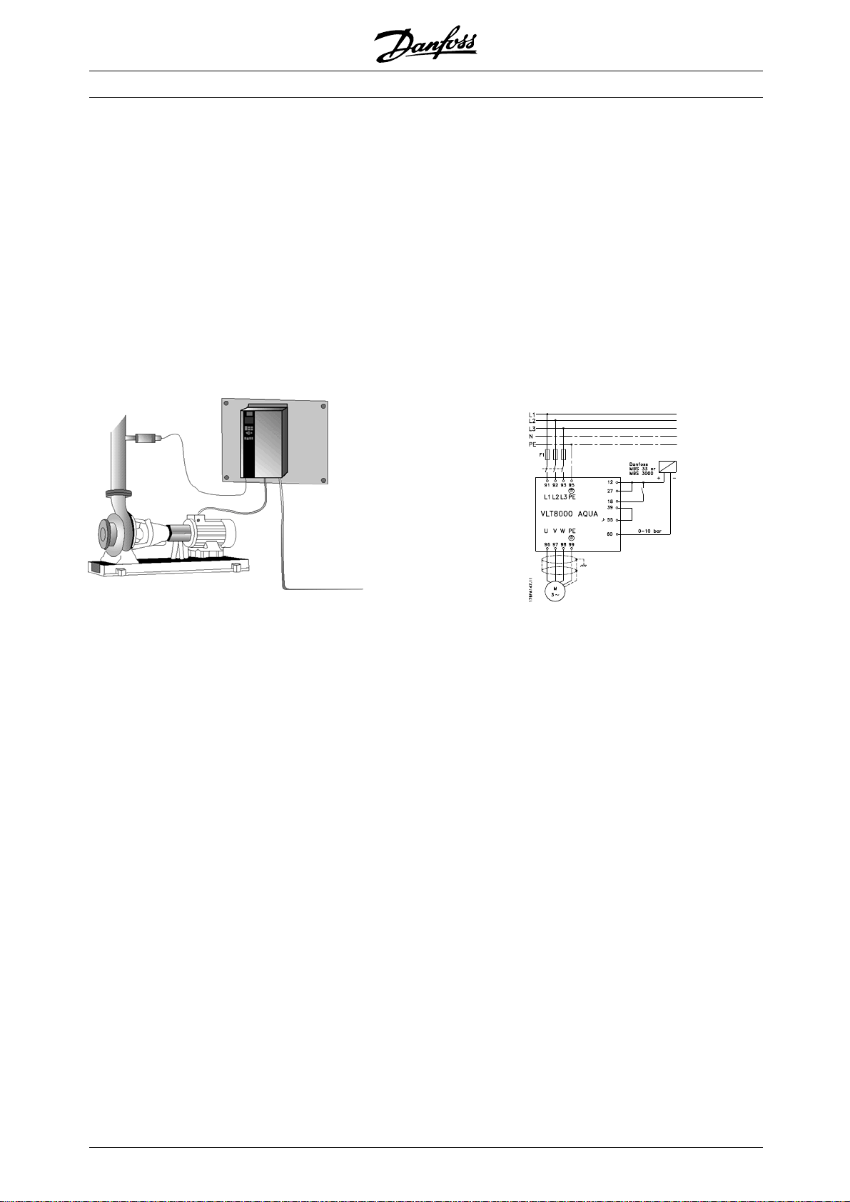
■Example of application - Constant pressure
regulation in water supply system
The demand for water from waterworks varies considerably during the course of a day. In the night,
practically no water is used, while in the morning and in the evening the consumption is high. In order to
maintain a suitable pressure in the water supply lines in relation to the current demand, the water supply
pumps are equipped with speed control. The use of a frequency converter enables the energy consumed by
the pumps to be kept at a minimum, while optimizing the water supply to consumers.
A VLT 8000 AQUA with its integral PID controller ensures simple and quick installation. For example, an
IP54/NEMA 12 unit can be mounted close to the pump on the wall and the existing mains cables can be
used as mains supply to the frequency converter. A Pressure transmitter (e.g. Danfoss MBS 33 or MBS
3000) can be fitted a few meters (feet) from the joint outlet point from the waterworks to obtain closed loop
regulation. Danfoss MBS 33 and MBS 3000 is a two-wire transmitter (4-20 mA) that can be powered directly
from a VLT 8000 AQUA. The required setpoint (e.g. 5 bar) can be set locally in parameter 418 Setpoint 1.
Assume:
Transmitter is scaled 0-10 Bar, minimum flow
is achieved at 30 Hz. An increase in motor
speed increases the pressure.
Set the following parameters:
Par. 100 Configuration Closed loop [1]
Par. 201 Minimum Output Frequency 30 Hz
Par. 202 Maximum Output Frequency 50 Hz (or 60 Hz)
Par. 204 Minimum Reference 0 Bar
Par. 205 Maximum Reference 10 Bar
Par. 302 Terminal 18 Digital inputs Start [1]
Par. 314 Terminal 60, analog input current Feedback signal [2]
Par. 315 Terminal 60, min. scaling 4 mA
Par. 316 Terminal 60, max. scaling 20 mA
Par. 403 Sleep mode timer 10 sec.
Par. 404 Sleep frequency 35 Hz
Par. 405 Wake-up frequency 45 Hz
Par. 406 Boost setpoint 125%
Par. 413 Minimum Feedback 0 Bar
Par. 414 Maximum Feedback 10 Bar
Par. 415 Process units Bar [16]
Par. 418 Setpoint 1 5 bar
Par. 420 PID control action Normal
Par. 423 PID Proportional gain 0.3*
Par. 424 PID Integral time 30 sec.*
* The PID tuning parameters depend on the actual system dynamics.
12
MG.83.A2.02 - VLT is a registered Danfoss trademark
Page 13
VLT®8000 AQUA
■PC software and serial communication
Danfoss offers various options for serial communication.
Using serial communication, it is possible to monitor,
program and control one or several frequency
converters from a centrally located computer.
All VLT 8000 AQUA units have an RS 485 port as
standard with a choice of two protocols. The protocols
selectable in parameter 500 protocols are:
• FC Protocol
• Modbus RTU
A bus option card allows higher transmission speed
than RS 485. In addition, a higher number of units
can be linked to the bus and alternative transmission
media can be used. Danfoss offers the following
option cards for communication:
• Profibus
• LonWorks
• DeviceNet
Information on the installation of various options is
not included in these operating instructions.
Using the RS 485 port enables communication,
TM
e.g. with a PC. A Windows
program, called
MCT 10, is available for this purpose. It can be
used to monitor, program and control one or
several VLT 8000 AQUA units.
■PC Software tools
PC Software - MCT 10
All drives are equipped with a serial communication
port. We provide a PC tool for communication
between PC and frequency converter, VLT Motion
Control Tool MCT 10 Set-up Software.
MCT 10 Set-up Software
MCT 10 has been designed as an easy to use interactive
tool for setting parameters in our frequency converters.
The MCT 10 Set-up Software will be useful for:
• Planning a communication network off-line. MCT 10
contains a complete frequency converter database
• Commissioning frequency converters on line
• Saving settings for all frequency converters
• Replacing a drive in a network
• Expanding an existing network
• Future developed drives will be supported
MCT10Set-upSoftwaresupportProfibusDP-V1via
a Master class 2 connection. It makes it possible to
on line read/write parameters in a frequency converter
via the Profibus network. This will eliminate the need
for an extra communication network.
The MCT 10 Set-up Software Modules
The following modules are included in the
software package:
MCT10Set-upSoftware
Setting parameters
Copy to and from frequency converters
Documentation and print out of parameter
settings incl. diagrams
SyncPos
Creating SyncPos programme
Ordering number:
Please order your CD containing MCT 10 Set-up
Software using code number 130B1000.
Introduction
■Fieldbus options
The increasing need for information in building
management systems makes it necessary to collect
or visualise many different types of process data.
Important process data can help the system technician
in the day to day monitoring of the system, which
means that a negative development, e. g. an increase
in energy consumption, can be rectified in time.
The substantial amount of data in large buildings
may generate a need for a higher transmission
speed than 9600 baud.
MG.83.A2.02 - VLT is a registered Danfoss trademark
■Profibus
Profibus is a fieldbus system with FMS and DP,
which can be used for linking automation units,
such as sensors and actuators, to the controls
by means of a two-conductor cable.
Profibus FMS is used if major communication
tasks are to be solved at cell and system level by
means of large volumes of data.
Profibus DP is an extremely fast communication
protocol, made specially for communication between
the automation system and various units.
VLT 8000 AQUA only supports DP.
13
Page 14

■LON - Local Operating Network
LonWorks is an intelligent fieldbus system which
improves the possibility of decentralising control,
as communication is enabled between individual
units in the same system (Peer-to-Peer).
This means that there is no need for a big main station
for handling all the signals of the system (Master-Slave).
Signals are sent direct to the unit that needs them
via a common network medium. This makes
communication much more flexible and the central
building state control and monitoring system can be
changed into a dedicated building state monitoring
system whose task is to ensure that everything is
running as planned. If the potential of LonWorks is
fully utilised, sensors will also be connected to the
bus, which means that a sensor signal can quickly
be moved to another controller. If room dividers are
mobile, this is a particularly useful feature.
■DeviceNet
DeviceNet is a digital, multi-drop network, based
on the CAN protocol, that connects and serves
as a communication network between industrial
controllers and I/O devices.
Each device and/or controller is a node on the
network. DeviceNet is a producer-consumer
network that supports multiple communication
hierarchies and message prioritization.
DeviceNet systems can be configured to operate in a
master-slave or a distributed control architecture using
peer-to-peer communication. This system offers a
single point of connection for configuration and control
by supporting both I/O and explicit messaging.
DeviceNet also has the feature of having power
on the network. This allows devices with limited
power requirements to be powered directly from
the network via the 5-conductor cable.
VLT®8000 AQUA
■Modbus RTU
MODBUS RTU (Remote Terminal Unit) Protocol is
a messaging structure developed by Modicon in
1979, used to establish master-slave/client-server
communication between intelligent devices.
MODBUS is used to monitor and program
devices; to communicate intelligent devices
with sensors and instruments; to monitor field
devicesusingPCsandHMIs.
MODBUS is often applied in Gas and Oil applications,
but also in building, infrastructure, transportation and
energy, applications are making use of its benefits.
14
MG.83.A2.02 - VLT is a registered Danfoss trademark
Page 15
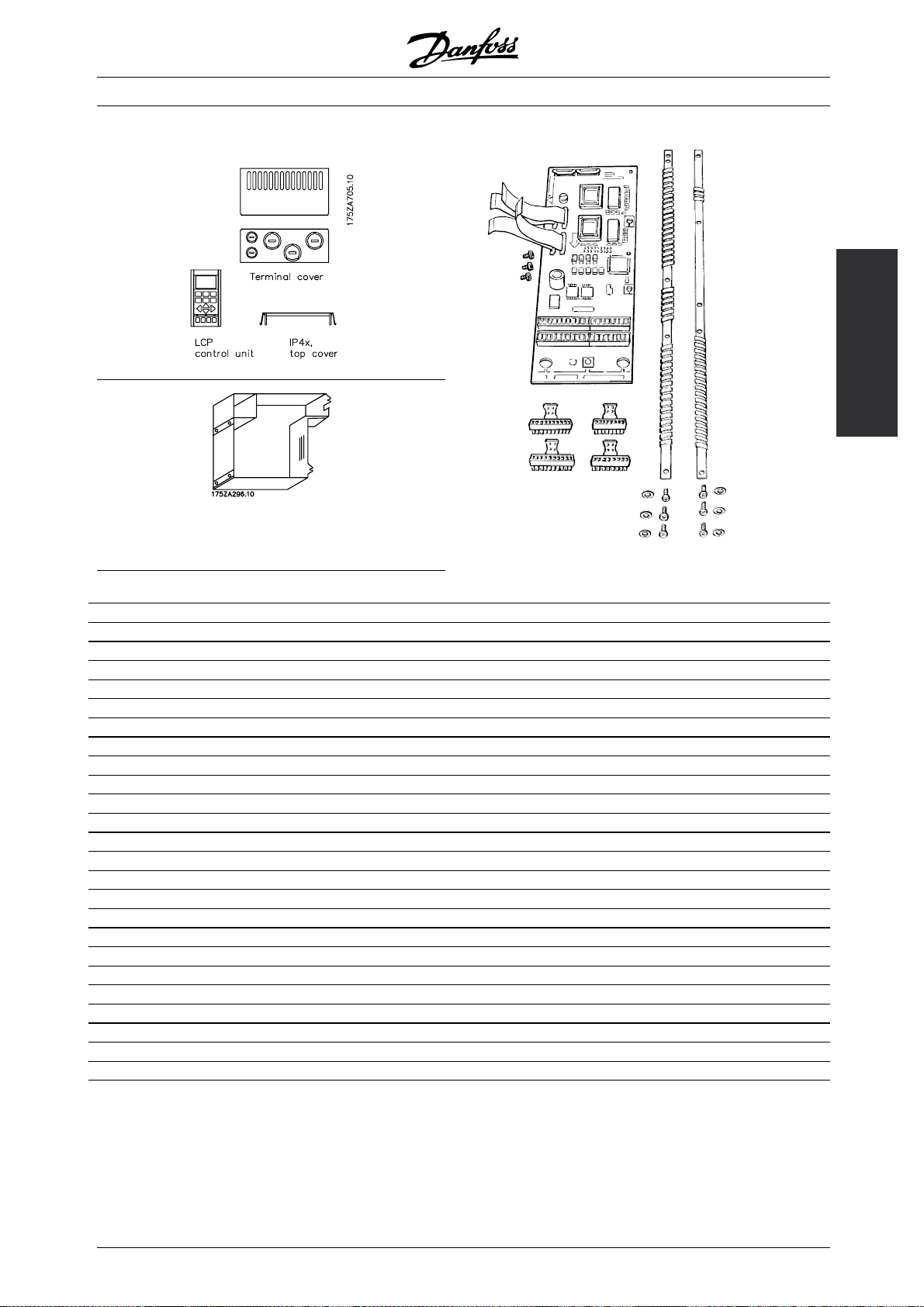
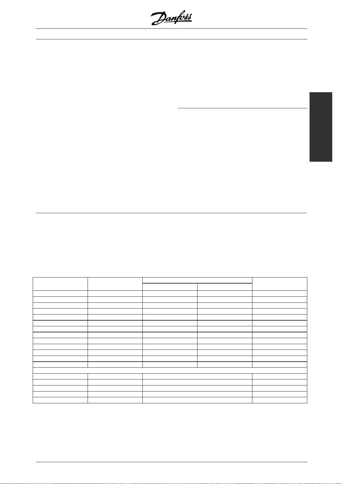
■Accessories
IP 20 bottom cover
VLT®8000 AQUA
Introduction
Application option
Type Description Order no.
IP 4x top cover IP
IP 4 x top cover
NEMA 12 bonding plate
IP 20 terminal cover Option, VLT type 8006-8022 200-240 V 175Z4622
IP 20 terminal cover Option, VLT type 8027-8032 200-240 V 175Z4623
IP 20 terminal cover Option, VLT type 8016-8042 380-480 V 175Z4622
IP 20 terminal cover Option, VLT type 8016-8042 525-600 V 175Z4622
IP 20 terminal cover Option, VLT type 8052-8072 380-480 V 175Z4623
IP 20 terminal cover Option, VLT type 8102-8122 380-480 V 175Z4280
IP 20 terminal cover Option, VLT type 8052-8072 525-600 V 175Z4623
IP 20 bottom cover Option, VLT type 8042-8062 200-240 V 176F1800
Terminal adaptor kit VLT type 8042-8062 200-240 V, IP 54 176F1808
Terminal adaptor kit VLT type 8042-8062 200-240 V, IP 00/NEMA 1 176F1805
Control panel LCP Separate LCP 175Z7804
LCP remote-mounting kit IP 00 & 20
LCP remote-mounting kit IP 54
LCP blind cover for all IP00/IP20 drives 175Z7806
Cable for LCP Separate cable (3 m) 175Z0929
Relay card Application card with four relay outputs 175Z3691
Cascade controller card With conformal coating 175Z3692
Profibus option Without/with conformal coating 175Z3685/175Z3686
LonWorks option, Free topology Without conformal coating 176F0225
Modbus RTU option Without conformal coating 175Z3362
DeviceNet option Without conformal coating 176F0224
MCT 10 Set-up software CD-Rom 130B1000
MCT 31 Harmonic calculation CD-Rom 130B1031
1)
1)
2)
3)
4)
Option, VLT type 8006-8011 380-480 V compact 175Z0928
Option, VLT type 8002-8011 525-600 V compact 175Z0928
Option, VLT type 8006-8011 380-480 V 175H4195
Remote-mounting kit, incl. 3 m cable 175Z0850
Remote-mounting kit, incl. 3 m cable 175Z7802
MG.83.A2.02 - VLT is a registered Danfoss trademark
15
Page 16

VLT®8000 AQUA
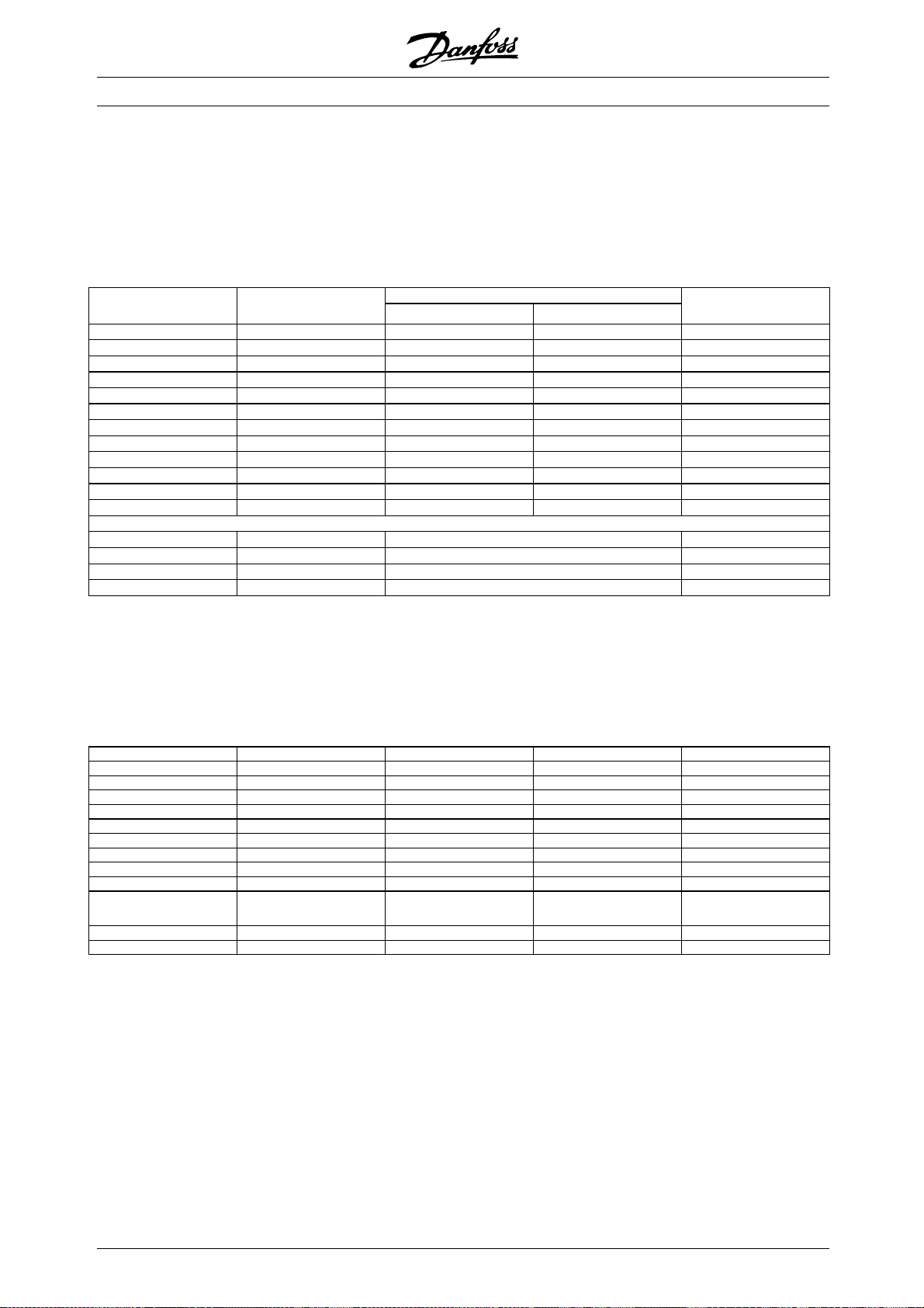
Rittal Installation Kit
Type Description Order No.
Rittal TS8 enclosure for IP00
Rittal TS8 enclosure for IP00
Rittal TS8 enclosure for IP00
Rittal TS8 enclosure for IP00
Rittal TS8 enclosure for IP00
Floor stand for IP21 and IP54
5)
enclosure
Mains shield kit Protection kit, VLT 8152-8352, 380-480 V; VLT 8052-8402, 525-690 V 176F0799
Mains shield kit Protection kit, VLT 8452-8652, 380-480 V; VLT 8502-8652, 525-690V 176F1851
1) IP 4x/NEMA 1 top cover is for IP 20 units only and only horizontal surfaces comply with IP 4x. The kit also
contains a bonding plate (UL).
2) NEMA 12 bonding plate (UL) is only for IP 54 units.
3) The remote-mounting kit is only for IP 00 and IP 20 units. Enclosure of the remote-mounting kit is IP 65.
4) The remote-mounting kit is only for IP 54 units. Enclosure of the remote-mounting kit is IP 65.
5) For details: See High Power Installation Guide, MI.90.JX.YY.
VLT 8000 AQUA is available with an integral fieldbus option or application option. Ordering numbers for the
individual VLT types with integrated options can be seen from the relevant manuals or instructions. In addition,
the ordering number system can be used for ordering a frequency converter with an option.
5)
Installation kit for 1800mm high enclosure, VLT8152-8202, 380-480V; VLT8052-8202, 525-690V 176F1824
5)
Installation kit for 2000mm high enclosure, VLT8152-8202, 380-480V; VLT8052-8202, 525-690V 176F1826
5)
Installation kit for 1800mm high enclosure, VLT8252-8352, 380-480V; VLT8252-8402, 525-690V 176F1823
5)
Installation kit for 2000mm high enclosure, VLT8252-8352, 380-480V; VLT8252-8402, 525-690V 176F1825
5)
Installation kit for 2000mm high enclosure, VLT8452-8652, 380-480V/VLT 8502-8652, 525-690V 176F1850
Option, VLT8152-8352, 380-480V; VLT 8052-8402, 525-690V 176F1827
16
MG.83.A2.02 - VLT is a registered Danfoss trademark
Page 17
■Cascade Controller Option
In "Standard Mode", one motor is controlled by
the drive that has the Cascade Controller Option
card installed in it. Up to four additional fixed speed
motors can be sequenced on & off, as required
by the process, in lead-lag mode.
In "Master/Slave Mode", the drive that has the
Cascade Controller option card installed in it, along
with its associated motor, is designated as the
master. Up to four additional motors, each with
its own drive, can be operated in slave mode. The
Cascade Controller functions to stage the slave
drives/motors - on & off (as required), as a function
of "best system operating efficiency".
In "Lead Pump Alternation Mode", it is possible to
averageouttheusageofthepumps.Thisisdoneby
making the frequency converter switch between the
pumps (max. 4) by means of a timer. Please note
that this mode requires an external relay setup.
VLT®8000 AQUA
This filter reduces the voltage rise time, the peak voltage
and the ripple current I to the motor, thereby
U
PEAK
making current and voltage almost sinusoidal. The
acoustic motor noiseis thereforereducedto a minimum.
Because of the ripple current in the coils, there will be
some noise from the coils. This problem can be solved
entirely by integrating the filter in a cabinet or similar.
Introduction
Consult your Danfoss Sales Office for
additional information.
■LC filters for VLT 8000 AQUA
When a motor is controlled by a frequency converter,
resonance noise will be heard from the motor. This
noise, which is caused by the design of the motor,
occurs each time one of the inverter switches in
the frequency converter is activated. Consequently,
the resonance noise frequency corresponds to the
switching frequency of the frequency converter.
For the VLT 8000 AQUA, Danfoss offers a LC filter
to dampen the acoustic motor noise.
■Examples of the use of LC filters
ubmersible pumps
S
For small motors with up to and including 5.5 kW
rated motor power, use an LC filter, unless the motor
is equipped with phase separation paper. This applies
e.g. to all wet running motors. If these motors are
used without LC filter in connection with a frequency
converter, the motor windings will short-circuit. If in
doubt, ask the motor manufacturer whether the motor
in question is equipped with phase separation paper.
ell pumps
W
If immersion pumps are used, e.g. submerged
pumps or well pumps, the supplier should be
contacted for clarification of requirements. It is
recommended to use a LC filter if a frequency converter
is used for well pump applications.
MG.83.A2.02 - VLT is a registered Danfoss trademark
17
Page 18
VLT®8000 AQUA
■Ordering numbers, LC filter modules
Mains supply 3 x 200 - 240 V
LC filter LC filter Rated current Max. output Power
for VLT type enclosure at 200 V frequency loss Order no.
8006-8008 IP 00 25.0 A 60 Hz 110 W 175Z4600
8011 IP 00 32 A 60 Hz 120 W 175Z4601
8016 IP 00 46 A 60 Hz 150 W 175Z4602
8022 IP 00 61 A 60 Hz 210 W 175Z4603
8027 IP 00 73 A 60 Hz 290 W 175Z4604
8032 IP 00 88 A 60 Hz 320 W 175Z4605
8042 IP 00 115 A 60 Hz 600 W 175Z4702
8052 IP 00 143 A 60 Hz 600 W 175Z4702
8062 IP 00 170 A 60 Hz 700 W 175Z4703
Mainssupply3x380-480
LC filter LC filter Rated current Max. output Power
for VLT type enclosure at 400/480 V frequency loss Order no.
8006-8011 IP 20 16 A / 16 A 120 Hz 175Z0832
8016 IP 00 24 A/ 21.7 A 60 Hz 170 W 175Z4606
8022 IP 00 32 A / 27.9 A 60 Hz 180 W 175Z4607
8027 IP 00 37.5 A / 32 A 60 Hz 190 W 175Z4608
8032 IP 00 44 A / 41.4 A 60 Hz 210 W 175Z4609
8042 IP 00 61 A / 54 A 60 Hz 290 W 175Z4610
8052 IP 00 73 A / 65 A 60 Hz 410 W 175Z4611
8062 IP 00 90 A / 78 A 60 Hz 480 W 175Z4612
8072 IP 20 106 A / 106 A 60 Hz 500 W 175Z4701
8102 IP 20 147 A / 130 A 60 Hz 600 W 175Z4702
8122 IP 20 177 A / 160 A 60 Hz 750 W 175Z4703
8152 IP 20 212 A / 190 A 60 Hz 750 W 175Z4704
8202 IP 20 260 A / 240 A 60 Hz 900 W 175Z4705
8252 IP 20 315 A / 302 A 60 Hz 1000 W 175Z4706
8302 IP 20 395 A / 361 A 60 Hz 1100 W 175Z4707
8352 IP 20 480 A / 443 A 60 Hz 1700 W 175Z3139
8452 IP 20 600 A / 540 A 60 Hz 2100 W 175Z3140
8502 IP 20 658 A / 590 A 60 Hz 2100 W 175Z3141
8602 IP 20 745 A / 678 A 60 Hz 2500 W 175Z3142
Regarding LC filters for 525 - 600 V and VLT 8652,
380-480 V, please contact Danfoss.
NB!:
When using LC filters, the switching frequency
must be 4.5 kHz (see parameter 407).
For VLT 8452-8602 parameter 408 must be set to
LC filter fitted to obtain proper operation.
18
MG.83.A2.02 - VLT is a registered Danfoss trademark
Page 19
Mainssupply3x690V
VLT®8000 AQUA
VLT
8052 54 60 290 130B2223 130B2258
8062 73 60 390 130B2225 130B2260
8072 86 60 480 130B2225 130B2260
8102 108 60 600 130B2226 130B2261
8122 131 60 550 130B2228 130B2263
8152 155 60 680 130B2228 130B2263
8202 192 60 920 130B2229 130B2264
8252 242 60 750 130B2231 130B2266
8302 290 60 1000 130B2231 130B2266
8352 344 60 1050 130B2232 130B2267
8402 400 60 1150 130B2234 130B2269
8502 530 60 500 130B2241 130B2270
8602 600 60 570 130B2242 130B2271
8652 630 60 600 - -
Rated Current at 690VMax. output
frequency (Hz)
Power
dissipation (W)
Ordering no. IP00
Ordering no.
IP20
dU/dt filters
The dU/dt filters reduce dU/dt to approx. 500 V / µsec. These filters do not red
uce noise or Upeak.
NB!:
When using dU/dt filters, the switching
frequency must be 1.5 kHz (see parameter 411)
Introduction
Mains supply3x690V
VLT
8052 54 60 90 130B2154 130B2188
8062 73 60 100 130B2155 130B2189
8072 86 60 110 130B2156 130B2190
8102 108 60 120 130B2157 130B2191
8122 131 60 150 130B2158 130B2192
8152 155 60 180 130B2159 130B2193
8202 192 60 190 130B2160 130B2194
8252 242 60 210 130B2161 130B2195
8302 290 60 350 130B2162 130B2196
8352 344 60 480 130B2163 130B2197
8402 400 60 540 130B2165 130B2199
8502 530 60 500 130B2236 130B2239
8602 600 60 570 130B2237 130B2240
8652 630 60 600 - -
Rated Current at 690VMax. output
frequency (Hz)
Power
dissipation (W)
Ordering no. IP 00
Ordering no.
IP20
MG.83.A2.02 - VLT is a registered Danfoss trademark
19
Page 20
VLT®8000 AQUA
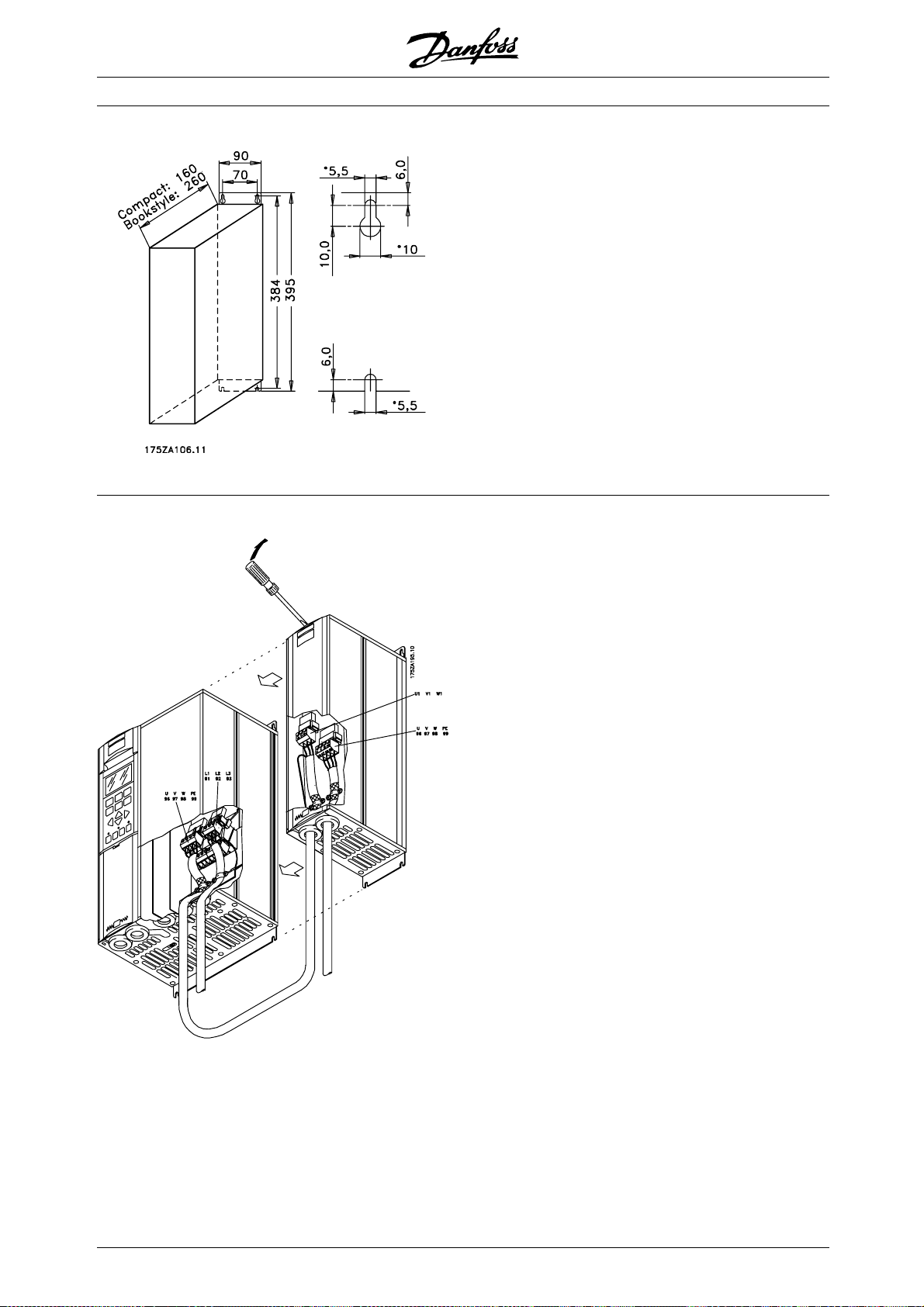
■LC filters VLT 8006-8011 380 - 480 V The drawing on the left gives the measurements of IP
20 LC filters for the above-mentioned power range.
Min. space above and under enclosure: 100 mm.
IP 20 LC filters have been designed for side-by-side
installation without any space between enclosures.
Max. motor cable length:
- 150 m screened/armoured cable
- 300 m unscreened/unarmoured cable
If EMC standards are to be complied with:
EN 55011-1B: Max. 50 screened/armoured
cable
EN 55011-1A: Max. 150 m screened/armoured
cable
Weight: 175Z0832 9.5 kg
■Installation of LC filter IP 20
20
MG.83.A2.02 - VLT is a registered Danfoss trademark
Page 21

VLT®8000 AQUA
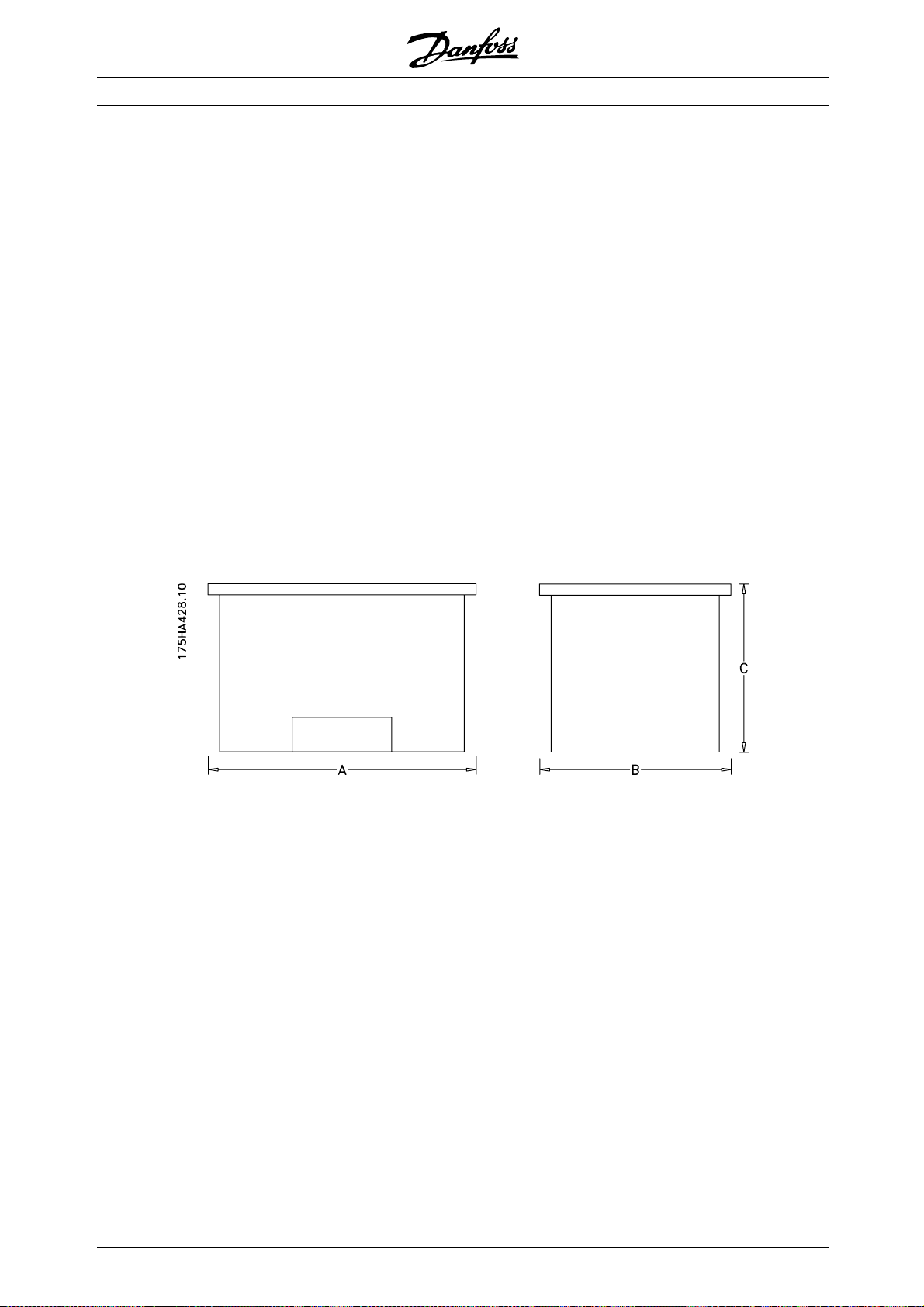
■LC filters VLT 8006-8032, 200 - 240 V /
8016-8062 380 - 480 V
The table and the drawing give the measurements
of IP 00 LC filters for Compact units.
IP 00 LC filters must be integrated and protected
against dust, water and corrosive gases.
Max. motor cable length:
- 150 m screened/armoured cable
- 300 m unscreened/unarmoured cable
If EMC standards are to be complied with:
- EN 55011-1B: Max. 50 screened/armoured
cable
- EN 55011-1A: Max. 150 m screened/armoured
cable
LC filter IP 00
LC type A [mm] B [mm] C [mm] D [mm] E [mm] F [mm] G [mm] Weight [kg]
175Z4600 220 135 92 190 68 170 8 10
175Z4601 220 145 102 190 78 170 8 13
175Z4602 250 165 117 210 92 180 8 17
175Z4603 295 200 151 240 126 190 11 29
175Z4604 355 205 152 300 121 240 11 38
175Z4605 360 215 165 300 134 240 11 49
175Z4606 280 170 121 240 96 190 11 18
175Z4607 280 175 125 240 100 190 11 20
175Z4608 280 180 131 240 106 190 11 23
175Z4609 295 200 151 240 126 190 11 29
175Z4610 355 205 152 300 121 240 11 38
175Z4611 355 235 177 300 146 240 11 50
175Z4612 405 230 163 360 126 310 11 65
Introduction
MG.83.A2.02 - VLT is a registered Danfoss trademark
21
Page 22
VLT®8000 AQUA
■LC filter VLT 8042-8062 200-240 V /
8072-8602 380 - 480 V
The table and the drawing give the measurements of IP
20 LC filters. IP 20 LC filters must be integrated and
protected against dust, water and aggressive gases.
Max. motor cable length:
- 150 m screened/armoured cable
- 300 m unscreened/unarmoured cable
If EMC standards are to be complied with:
- EN 55011-1B: Max. 50 m screened/armoured
cable
- EN 55011-1A: Max. 150 m screened/armoured
cable
LC-filter IP 20
LC type A [mm] B [mm] C [mm] D [mm] E [mm] F [mm] G [mm] Weight [kg]
175Z4701 740 550 600 70
175Z4702 740 550 600 70
175Z4703 740 550 600 110
175Z4704 740 550 600 120
175Z4705 830 630 650 220
175Z4706 830 630 650 250
175Z4707 830 630 650 250
175Z3139 1350 800 1000 350
175Z3140 1350 800 1000 400
175Z3141 1350 800 1000 400
175Z3142 1350 800 1000 470
22
MG.83.A2.02 - VLT is a registered Danfoss trademark
Page 23
VLT®8000 AQUA
■Harmonic filter
Harmonic currents do not directly affect the electricity
consumption but has an impact on following conditions:
Higher total current to be handled by the installations
- Increases load on transformer (sometimes it will
require a larger transformer, particular at retrofit)
- Increases heat losses in transformer and installation
- In some cases demands larger cables,
switches and fuses
Higher voltage distortion due to higher current
- Increase risk for disturbing electronic equipment
connected to same grid
A high percentage of rectifier load from eg frequency
converters, will increase the harmonic current, which
must be reduced to avoid the above consequences.
Therefore the frequency converter has as standard,
built in DC coils reducing the total current with about
40% (compared to devices without any arrangement
for harmonic suppression), down to 40-45% ThiD.
In some cases there is a need for further suppression
(eg retrofit with frequency converters). For this purpose
Danfoss can offer two advanced harmonic filters
AHF05 and AHF10, bringing the harmonic current
down to around 5% and 10% respectively. For further
details see instruction MG.80.BX.YY.
MCT 31
The MCT 31 harmonic calculation PC tool enables
easy estimation of the harmonic distortion in a given
application. Both the harmonic distortion of Danfoss
frequency converters as well as non-Danfoss frequency
converters with different additional harmonic reduction
measurements, such as Danfoss AHF filters and
12-18-pulse rectifiers, can be calculated.
Ordering number:
Please order your CD containing the MCT 31 PC
tool using code number 130B1031.
Introduction
■Ordering numbers, Harmonic filters
Harmonic filters are used to reduce mains harmonics
• AHF 010: 10% current distortion
• AHF 005: 5% current distortion
380-415 V, 50 Hz
AHF,N
10 A 4, 5.5 175G6600 175G6622 8006, 8008
19 A 7.5 175G6601 175G6623 8011, 8016
26 A 11 175G6602 175G6624 8022
35 A 15, 18.5 175G6603 175G6625 8027
43 A 22 175G6604 175G6626 8032
72 A 30, 37 175G6605 175G6627 8042, 8052
101 A 45. 55 175G6606 175G6628 8062, 8072
144 A 75 175G6607 175G6629 8102
180 A 90 175G6608 175G6630 8122
217 A 110 175G6609 175G6631 8152
289 A 132, 160 175G6610 175G6632 8202, 8252
324 A 175G6611 175G6633
370 A 200 175G6688 175G6691 8302
Higher ratings can be achieved by paralleling the filter units
434 A 250 Two 217 A units 8352
578 A 315 Two 289 A units 8452
613 A 355 289 A and 324 A units 8502
648 A 400 Two 324 A units 8602
740 A 450 Two 370 A units 8652
Typical Motor Used
[kW]
Danfoss ordering numberI
AHF 005 A HF 010
VLT 8000
MG.83.A2.02 - VLT is a registered Danfoss trademark
23
Page 24
VLT®8000 AQUA
Please note that the matching of the typical Danfoss frequency converter and filter is pre-calculated based on
400 V and assuming typical motor load (4 or 2 pole motor). VLT 8000 is based on a max. 110% torque
application.
The pre-calculated filter current may be different than the input current ratings of VLT 8000 as stated in the
respective operating instructions, as these numbers are based on different operating conditions.
440-480 V, 60 Hz
AHF,N
19 A 10, 15 175G6612 175G6634 8011, 8016
26 A 20 175G6613 175G6635 8022
35 A 25, 30 175G6614 175G6636 8027, 8032
43 A 40 175G6615 175G6637 8042
72 A 50, 60 175G6616 175G6638 8052, 8062
101 A 75 175G6617 175G6639 8072
144 A 100, 125 175G6618 175G6640 8102, 8122
180 A 150 175G6619 175G6641 8152
217 A 200 175G6620 175G6642 8202
289 A 250 175G6621 175G6643 8252
324 A 300 175G6689 175G6692 8302
370 A 350 175G6690 175G6693 8352
Higher ratings can be achieved by p
506 A 450 217 A and 289 A units 8452
578 A 500 Two 289 A units 8502
578 A 550 Two 289 A units 8602
648 A 600 Two 324 A units 8652
Typical Motor Used
[HP]
aralleling the filter units
Danfoss ordering numberI
AHF 005 A HF 010
VLT 8000
Please note that the matching of the Danfoss frequency converter and filter is pre-calculated based on 480 V
and assuming typical motor load. VLT 8000 is based on 110 % torque application.
The pre-calculated filter current may be varying from the input current ratings of VLT 8000 as stated in the
respective operating instructions, as these numbers are based on different operating conditions.
690 V, 50 Hz
IAHF,N Ty p ic a l m o to r u s ed Ordering no. AHF 005 Ordering no. AHF 010 VLT 8000 110%
43 37, 45 130B2328 130B2293 8052
72 55, 75 130B2330 130B2295 8062, 8072
101 90 130B2331 130B2296 8102
144 110, 132 130B2333 130B2298 8122, 8152
180 160 130B2334 130B2299 8202
217 200 130B2335 130B2300 8252
289 250 130B2331 & 130B2333 130B2301 8302
324 315 130B2333 & 130B2334 130B2302 8352
370 400 130B2334 & 130B2335 130B2304 8402
469 500 130B2333 & 2 x
130B2334
578 560 3 x 130B2334 2 x 130B2301 8602
613 630 3 x 130B2335 130B2301 & 130B2302 8652
130B2299 & 130B2301 8502
24
MG.83.A2.02 - VLT is a registered Danfoss trademark
Page 25

VLT®8000 AQUA
■Unpacking and ordering a VLT frequency converter
If you are in doubt as to which frequency converter
you have received and which options it contains,
use the following to find out.
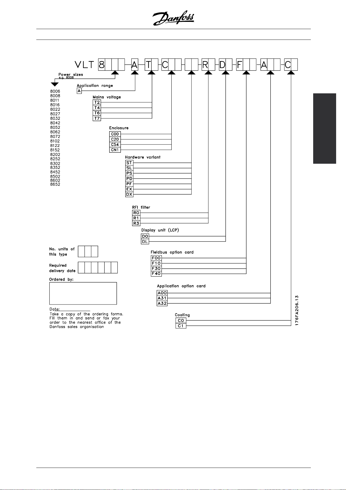
■Type code ordering number string
On the basis of your order, the frequency converter is
given an ordering number that can be seen from the
nameplate on the unit. The number may look as follows:
VLT-8008-A-T4-C20-R3-DL-F10-A00-C0
This means that the frequency converter ordered is a
VLT 8008 for three-phase mains voltage of 380-480 V
(T4) in Compact enclosure IP 20 (C20). The hardware
variant is with integral RFI filter, classes A & B (R3). The
frequency converter features a control unit (DL)witha
PROFIBUS option card (F10). No option card (A00)
and no conformal coating (C0) Character no. 8 (A)
indicates the application range of the unit: A =AQUA.
IP 00: This enclosure is only available for the larger
power sizes of the VLT 8000 AQUA series. It is
recommended for installation in standard cabinets.
IP 20/NEMA 1: This enclosure is used as standard
enclosure for VLT 8000 AQUA. It is ideal for
cabinet installation in areas where a high degree
of protection is required. This enclose also
permits side-by-side installation.
IP 54: This enclosure can be fitted direct to the
wall. Cabinets are not required. IP 54 units can
also be installed side-by-side.
Hardware variant
Theunitsintheprogrammeareavailableinthe
following hardware variants:
ST: Standard unit with or without control
unit. Without DC terminals, except for
VLT 8042-8062, 200-240 V
VLT 8016-8300, 525-600 V
SL: Standard unit with DC terminals.
EX: Extended unit with control unit, DC
terminals, connection of external 24 V
DC supply for back-up of control PCB.
DX: Extended unit with control unit, DC
terminals, built-in mains fuses and
disconnector, connection of external 24
V DC supply for back-up of control PCB.
PF: Standard unit with 24 V DC supply for
back-up of control PCB and built-in
main fuses. No DC terminals.
PS: Standard unit with 24 V DC supply
for back-up of control PCB. No DC
terminals.
PD: Standard unit with 24 V DC supply for
back-up of control PCB, built-in main
fuses and disconnect. No DC terminals.
RFI filter
Units for a mains voltage of 380-480 V and a motor
power of up to 7.5 kW (VLT 8011) are always
supplied with an integral class A1 & B filter. Units
for higher motor power than these can be ordered
either with or without an RFI filter. RFI filters are not
available for 525-600 V units.
Introduction
A1 RFI is not offered on the VLT 8502 -8652 525-690V
Control unit (keypad and display)
All types of units in the programme, except for IP
54 units (and IP 21 VLT 8452-8652, 380-480 V and
VLT 8502-8652, 525-690 V), can be ordered either
with or without the control unit. IP 54 units always
come with acontrolunit.
All types of units in the programme are available
with built-in application options including a relay
card with four relays or a cascade controller card.
Conformal Coating
All types of units in the programme are available
with or without conformal coating of the PCB.
Please note VLT 8452-8652, 380-480 V and
VLT 8052-8652, 525-690 V are only available as
conformal coated.
MG.83.A2.02 - VLT is a registered Danfoss trademark
25
Page 26
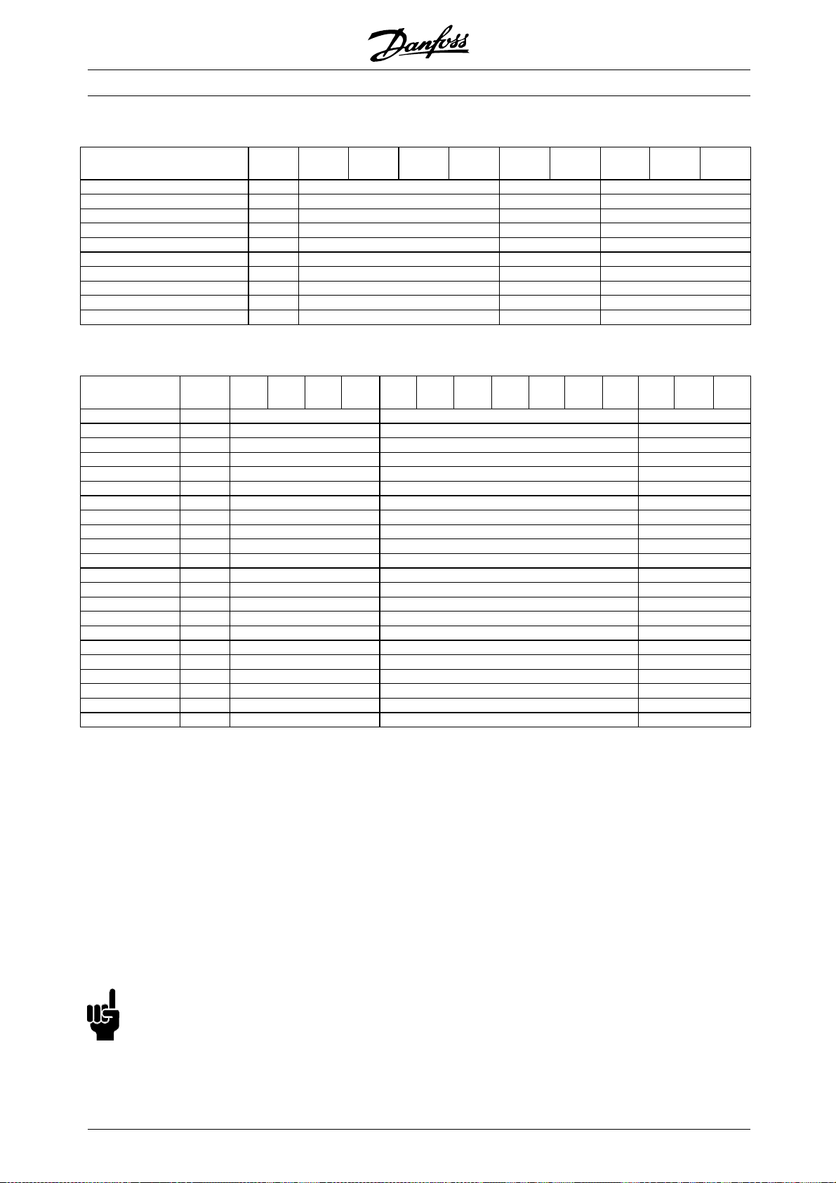
200-240 V
VLT®8000 AQUA
Typecode
Position in string
T2
9-10
C00
11-13
C20
11-13
CN1
11-13
C54
11-13ST14-15SL14-15R016-17R116-17R316-17
4.0 kW/5.0 HP 8006 XXXXXX
5.5 kW/7.5 HP 8008 XXXXXX
7.5 kW/10 HP 8011 XXXXXX
11 kW/15 HP 8016 XXXXXX
15 kW/20 HP 8022 XXXXXX
18.5 kW/25 HP 8027 XXXXXX
22 kW/30 HP 8032 XXXXXX
30 kW/40 HP 8042 XXXX XX
37 kW/50 HP 8052 XXXX XX
45 kW/60 HP 8062 XXXX XX
380-480 V
Typecode
Position in stringT49-10
4.0 kW/5.0 HP 8006 XXXX X
5.5 kW/7.5 HP 8008 XXXX X
7.5 kW/10 HP 8011 XXXXX
11 kW/15 HP 8016 XXXX X XX
15 kW/20 HP 8022 XXXX X XX
18.5 kW/25 HP 8027 XXXX X XX
22 kW/30 HP 8032 XXXX X XX
30 kW/40 HP 8042 XXXX X XX
37 kW/50 HP 8052 XXXX X XX
45 kW/60 HP 8062 XXXX X XX
55 kW/75 HP 8072 XXXX X XX
75 kW/100 HP 8102 XXXX X XX
90 kW/125 HP 8122 XXXX X XX
110 kW/150 HP 8152 XXXXXXXXXXX
132 kW/200 HP 8202 XXXXXXXXXXX
160 kW/250 HP 8252 XXXXXXXXXXX
200 kW/300 HP 8302 XXXXXXXXXXX
250 kW/350 HP 8352 XXXXXXXXXXX
315 kW/450 HP 8452 XXXXXXXXXXX
355 kW/500 HP 8502 XXXXXXXXXXX
400 kW/550 HP 8602 XXXXXXXXXXX
450 kW/600 HP 8652 XXXXXXXXXXX
C00
11-13
C20
11-13
CN1
C54
11-13
11-13ST14-15SL14-15EX14-15DX14-15PS14-15PD14-15PF14-15R016-17R116-17R316-17
Voltage
T2: 200-240 VAC
T4: 380-480 VAC
Enclosure
C00: Compact IP 00
C20: Compact IP 20
CN1: Compact NEMA 1
C54: Compact IP 54
NB!:
NEMA 1 exceeds IP 20
26
Hardware variant
ST: Standard
SL: Standard with DC terminals
EX: Extended with 24 V supply and DC terminals
DX: Extended with 24 V supply, DC terminals, disconnect and fuse
PS: Standard with 24 V supply
PD: Standard with 24 V supply, fuse and disconnect
PF: Standard with 24 V supply and fuse
RFI filter
R0: Without filter
R1: Class A1 filter
R3: Class A1 and B filter
MG.83.A2.02 - VLT is a registered Danfoss trademark
Page 27
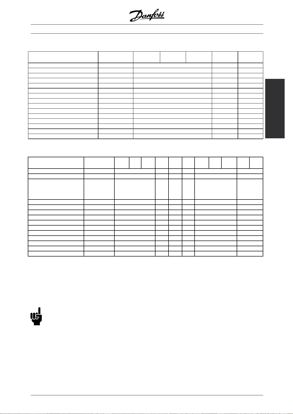
525-600 V
VLT®8000 AQUA
Typecode
Position in string
1.1 kW/1.5 HP 8002 XXX X
1.5 kW/2.0 HP 8003 XXX X
2.2 kW/3.0 HP 8004 XXX X
3.0 kW/4.0 HP 8005 XXX X
4.0 kW/5.0 HP 8006 XXX X
5.5 kW/7.5 HP 8008 XXX X
7.5 kW/10 HP 8011 XXX X
11 kW/15 HP 8016 X X X
15 kW/20 HP 8022 X X X
18.5 kW/25 HP 8027 X X X
22 kW/30 HP 8032 X X X
30 kW/40 HP 8042 X X X
37 kW/50 HP 8052 X X X
45 kW/60 HP 8062 X X X
55 kW/75 HP 8072 X X X
T6
9-10
C00
11-13
C20
11-13
CN1
11-13
ST
14-15
R0
16-17
525-690 V
Typecode
Position in string
45 kW/50 HP 8052 XXXX X X XX X XX
55 kW/60 HP 8062 XXXX X X XX X XX
75 kW/75 HP 8072 XXXX X X XX X XX
T7
9-10
C00
11-13
CN1
C54
11-13
11-13ST11-13EX11-13DX14-15PS14-15PD14-15PF14-15R016-17R116-17
Introduction
1)
90 kW/100 HP 8102 XXXX X X XX XXX
110 kW/125 HP 8122 XXXX X X XX XXX
132 kW/150 HP 8152 XXXX X X XX XXX
160 kW/200 HP 8202 XXXX X X XX XXX
200 kW/250 HP 8252 XXXX X X XX XXX
250 kW/300 HP 8302 XXXX X X XX XXX
315 kW/350 HP 8352 XXXX X X XX XXX
400 kW/400 HP 8402 XXXX X X XX XXX
500 kW/400 HP 8502 XXXX X X XX XX
560 kW/500 HP 8602 XXXX X X XX XX
630 kW/600 HP 8652 XXXX X X XX XX
1) R1 is not available with DX, PF and PD variants.
T7: 525-690 VAC
C00: Compact IP 00
C20: Compact IP 20
CN1: Compact NEMA 1
ST: Standard
R0: Without filter
R1: Class A1 filter
NB!:
NEMA 1 exceeds IP 20
MG.83.A2.02 - VLT is a registered Danfoss trademark
27
Page 28
Optional selections, 200-600 V
Display Position: 18-19
D01)Without LCP
DL With LCP
Fieldbus option Position: 20-22
F00 No options
F10 Profibus DP V1
F30 DeviceNet
F40 LonWorks free topology
Application option Position: 23-25
A00 No options
A312)Relay card 4 relays
A32 Cascade Controller
Coating Position: 26-27
C03)No coating
C1 With coating
1) Not available with enclosure compact IP 54
2) Not available with fieldbus options (Fxx)
3) Not available for power sizes from 8452 to 8652, 380-480 V and VLT
8052-8652, 525-690 V
VLT®8000 AQUA
28
MG.83.A2.02 - VLT is a registered Danfoss trademark
Page 29
■TYPE CODE Table/Ordering form
VLT®8000 AQUA
Introduction
MG.83.A2.02 - VLT is a registered Danfoss trademark
29
Page 30

VLT®8000 AQUA
■General technical data
Mains supply (L1, L2, L3):
Supply voltage 200-240 V units ........................................................................ 3 x 200/208/220/230/240 V ±10%
Supply voltage 380-480 V units ................................................................ 3 x 380/400/415/440/460/480 V ±10%
Supply voltage 525-600 V units ............................................................................... 3 x 525/550/575/600 V ±10%
Supply voltage 525-690 V units ........................................................................ 3 x 525/550/575/600/690 V ±10%
Supply frequency ......................................................................................................................... 48-62 Hz +/- 1%
Max imbalance of supply voltage:
VLT 8006-8011/380-480 V and VLT 8002-8011/525-600 V .................................... ±2.0% of rated supply voltage
VLT 8016-8072/525-600 V, 380-480 V and VLT 8006-8032/200-240 V ................. ±1.5% of rated supply voltage
VLT 8102-8652/380-480 V and VLT 8042-8062/200-240 V ................................... ±3.0% of rated supply voltage
VLT 8052-8652/525-690 V ..................................................................................... ±3.0% of rated supply voltage
Displacement factor / cos. ϕ ...................................................................................................... near unity (> 0.98)
True Power Factor (λ) ..................................................................................................... nominal 0.90 at rated load
Input Mains (L1, L2, L3) Allowable On-OFF Switching Sequences ......................................... approx. 1 time/2 min.
Max. short-circuit current ............................................................................................................................ 100 kA
VLT output data (U, V, W):
Output voltage ................................................................................................................ 0-100% of supply voltage
Output frequency 8006-8032, 200-240V ............................................................................ 0 - 120 Hz, 0-1000 Hz
Output frequency 8042-8062, 200-240V .............................................................................. 0 - 120 Hz, 0-450 Hz
Output frequency 8072-8652, 380-460V .............................................................................. 0 - 120 Hz, 0-450 Hz
Output frequency 8002-8016, 525-600V ............................................................................ 0 - 120 Hz, 0-1000 Hz
Output frequency 8022-8062, 525-600V .............................................................................. 0 - 120 Hz, 0-450 Hz
Output frequency 8072, 525-600V ....................................................................................... 0 - 120 Hz, 0-450Hz
Output frequency 8052-8352, 525-690V .............................................................................. 0 - 132 Hz, 0-200 Hz
Output frequency 8402-8652, 525-690V .............................................................................. 0 - 132 Hz, 0-150 Hz
Rated motor voltage, 200-240 V units .............................................................................. 200/208/220/230/240V
Rated motor voltage, 380-480 V units ...................................................................... 380/400/415/440/460/480 V
Rated motor voltage, 525-600 V units ............................................................................................ 525/550/575 V
Rated motor voltage, 525-690 V units ..................................................................................... 525/550/575/690 V
Rated motor frequency ............................................................................................................................ 50/60 Hz
Switching on output ................................................................................................................................. Unlimited
Ramp times ........................................................................................................................................ 1- 3600 sec.
Torque characteristics:
Starting torque ............................................................................................................................... 110% for 1 min.
Starting torque (parameter 110 High break-away torque) ....................................... Max. torque: 130% for 0.5 sec.
Acceleration torque ....................................................................................................................................... 100%
Overload torque ............................................................................................................................................ 110%
30
MG.83.A2.02 - VLT is a registered Danfoss trademark
Page 31

VLT®8000 AQUA
Control card, digital inputs:
Number of programmable digital inputs ................................................................................................................ 8
Terminal nos. ............................................................................................................ 16, 17, 18, 19, 27, 29, 32, 33
Voltage level ........................................................................................................... 0-24 V DC (PNP positive logics)
Voltage level, logical "0" ........................................................................................................................... < 5 V DC
Voltage level, logical "1" ......................................................................................................................... > 10 V DC
Maximum voltage on input ........................................................................................................................ 28 V DC
Input resistance, R
Scanning time per input ............................................................................................................................. 3 msec.
Reliable galvanic isolation: All digital inputs are galvanically isolated from the supply voltage (PELV). In
addition, the digital inputs can be isolated from the other terminals on the control card by connecting
an external 24 V DC supply and opening switch 4. See switches 1-4.
Control card, analog inputs:
No. of programmable analog voltage inputs/thermistor inputs .............................................................................. 2
Terminal nos. ................................................................................................................................................ 53, 54
Voltage level .......................................................................................................................... 0 - 10 V DC (scalable)
Input resistance, R
No. of programmable analog current inputs .......................................................................................................... 1
Terminal no. earth ............................................................................................................................................... 55
Current range ...................................................................................................................... 0/4 - 20 mA (scalable)
Input resistance, R
Resolution .......................................................................................................................................... 10 bit + sign
Accuracy on input .......................................................................................................... Max. error 1% of full scale
Scanning time per input ............................................................................................................................. 3 msec.
Reliable galvanic isolation: All analog inputs are galvanically isolated from the supply voltage
(PELV) and other high-voltage terminals.
........................................................................................................................... approx. 2 k
i
......................................................................................................................... approx.10k
i
......................................................................................................................... approx. 200
i
Installation
Control card, pulse input:
No. of programmable pulse inputs ........................................................................................................................ 3
Terminal nos. .......................................................................................................................................... 17, 29, 33
Max. frequency on terminal 17 ...................................................................................................................... 5 kHz
Max. frequency on terminals 29, 33 ............................................................................ 20 kHz (PNP open collector)
Max. frequency on terminals 29, 33 ........................................................................................... 65 kHz (Push-pull)
Voltage level ........................................................................................................... 0-24 V DC (PNP positive logics)
Voltage level, logic "0" .............................................................................................................................. < 5 V DC
Voltage level, logic "1" ............................................................................................................................ > 10 V DC
Maximum voltage on input ........................................................................................................................ 28 V DC
Input resistance, R
........................................................................................................................... approx. 2 k
i
Scanning time per input ............................................................................................................................. 3 msec.
Resolution .......................................................................................................................................... 10 bit + sign
Accuracy (100-1 kHz), terminals 17, 29, 33 ............................................................... Max. error: 0.5% of full scale
Accuracy (1-5 kHz), terminal 17 ................................................................................. Max. error: 0.1% of full scale
Accuracy (1-65 kHz), terminals 29, 33 ....................................................................... Max. error: 0.1% of full scale
Reliable galvanic isolation: All pulse inputs are galvanically isolated from the supply voltage (PELV). In
addition, pulse inputs can be isolated from the other terminals on the control card by connecting an
external 24 V DC supply and opening switch 4. See switches 1-4.
Control card, digital/pulse and analog outputs:
No. of programmable digital and analog outputs ................................................................................................. 2
Terminal nos. ................................................................................................................................................ 42, 45
Voltage level at digital/pulse output ...................................................................................................... 0 - 24 V DC
Minimum load to frame (terminal 39) at digital/pulse output .......................................................................... 600
MG.83.A2.02 - VLT is a registered Danfoss trademark
31
Page 32

VLT®8000 AQUA
Frequency ranges (digital output used as pulse output) ............................................................................ 0-32 kHz
Current range at analog output ............................................................................................................ 0/4 - 20 mA
Maximum load to frame (terminal 39) at analog output ................................................................................ 500
Accuracy of analog output ......................................................................................... Max. error: 1.5% of full scale
Resolution on analog output. ........................................................................................................................... 8 bit
Reliable galvanic isolation: All digital and analog outputs are galvanically isolated from the
supply voltage (PELV) and other high-voltage terminals.
Control card, 24 V DC supply:
Terminal nos. ................................................................................................................................................ 12, 13
Max. load .................................................................................................................................................. 200 mA
Terminal nos. earth ....................................................................................................................................... 20, 39
Reliable galvanic isolation: The 24 V DC supply is galvanically isolated from the supply voltage
(PELV), but has the same potential as the analog outputs.
Control card, RS 485 serial communication :
Terminal nos. .............................................................................................................. 68 (TX+, RX+), 69 (TX-, RX-)
Reliable galvanic isolation: Full galvanic isolation (PELV).
Relay outputs:
No. of programmable relay outputs ...................................................................................................................... 2
Terminal nos., control card (resistive load only) ....................................................................................... 4-5 (make)
Max. terminal load (AC1) on 4-5, control card ........................................................................ 50 V AC, 1 A, 50 VA
Max. terminal load (DC1 (IEC 947)) on 4-5, control card ................................. 25 V DC, 2 A / 50 V DC, 1 A, 50 W
Max. terminal load (DC1) on 4-5, control card for UL/cUL applications .................... 30 V AC, 1 A / 42.5 V DC, 1A
Terminal nos., power card (resistive and inductive load) ...................................................... 1-3 (break), 1-2 (make)
Max. terminal load (AC1) on 1-3, 1-2, power card ............................................................. 250 V AC, 2 A, 500 VA
Max. terminal load (DC1 (IEC 947)) on 1-3, 1-2, power card ............................. 25 V DC, 2 A / 50 V DC, 1A, 50 W
Min. terminal load (AC/DC) on 1-3, 1-2, power card ....................................... 24 V DC, 10 mA / 24 V AC, 100 mA
1)
1) Rated values for up to 300,000 operations.
At inductive loads the number of operations are reduced by 50%, alternatively the current can be reduced by
50%, thus the 300,000 operations are maintained.
External 24 Volt DC supply :
Terminal nos. ................................................................................................................................................ 35, 36
Voltage range ....................................................................................... 24 V DC ±15% (max. 37 V DC for 10 sec.)
Max. voltage ripple ..................................................................................................................................... 2 V DC
Power consumption .............................................................................. 15 W - 50 W (50 W for start-up, 20 msec.)
Min. pre-fuse ............................................................................................................................................... 6 Amp
Reliable galvanic isolation: Full galvanic is
olation if the external 24 V DC supply is also of the PELV type.
32
MG.83.A2.02 - VLT is a registered Danfoss trademark
Page 33

VLT®8000 AQUA
Cable lengths and cross-sections:
Max. motor cable length, screened cable ........................................................................................... 150m/500 ft
Max. motor cable length, unscreened cable ..................................................................................... 300m/1000 ft
Max. motor cable length, screened cable VLT 8011 380-480 V .......................................................... 100m/330 ft
Max. motor cable length, screened cable VLT 8011 525-600 V ............................................................ 50m/164 ft
Max. DC-bus cable length, screened cable .................................... 25m/82 ft from frequency converter to DC bar.
Max. cable cross-section to motor, see next section
2
Max. cross-section for 24 V external DC supply ........................................................................ 2.5 mm
Max. cross-section for control cables ........................................................................................ 1.5 mm
Max. cross-section for serial communication ............................................................................. 1.5 mm
If UL/cUL is to be complied with, copper cable with temperature class 60/75°C / 140/167°F must be used
(VLT 8002 - 8072 (525 - 600 V), VLT 8006 - 8072 (380 - 480 V) and VLT 8002 - 8032 (200 - 240V). If
UL/cUL is to be complied with, copper cable with temperature class 75°C/167°F must be used (VLT 8102
- 8652 (380 - 480 V), VLT 8042 - 8062 (200 - 240 V), VLT 8052 - 8652 (525-690 V)).
Connectors are for use of both copper and aluminium cables, unless other is specified.
Control characteristics:
Frequency range .................................................................................................................................... 0 - 120 Hz
Resolution on output frequency ............................................................................................................. ±0.003 Hz
System response time ............................................................................................................................... 3 msec.
Speed, control range (open loop) ..................................................................................... 1:100 of synchro. speed
Speed, accuracy (open loop) .............................................................................. < 1500 rpm:max. error ± 7.5 rpm
> 1500 rpm: max. error of 0.5% of actual speed
Process, accuracy (closed loop) ......................................................................... < 1500 rpm: max.error ± 1.5 rpm
> 1500 rpm: max. error of 0.1% of actual speed
All control characteristics are based on a 4-pole asynchronous motor
/12 AWG
2
/16 AWG
2
/16 AWG
Installation
Accuracy of display readout (parameters 009-012 Display readout):
Motor current, 0 - 140% load ................................................................. Max. error: ±2.0% of rated output current
Power kW, Power HP, 0 - 90% load ........................................................ Max. error: ±5.0% of rated output power
MG.83.A2.02 - VLT is a registered Danfoss trademark
33
Page 34

VLT®8000 AQUA
Externals:
Enclosure .................................................................................. IP00/Chassis, IP20/IP21/NEMA 1, IP54/NEMA 12
Vibration test .................................. 0.7 g RMS 18-1000 Hz random. 3 directions for 2 hours (IEC 68-2-34/35/36)
Max. relative humidity ............................................................. 93 % +2 %, -3 % (IEC 68-2-3) for storage/transport
Max. relative humidity ................................................ 95% non condensing (IEC 721-3-3; class 3K3) for operation
Aggressive environment (IEC 721-3-3) .................................................................................... Uncoated class 3C2
Aggressive environment (IEC 721-3-3) ........................................................................................ Coated class 3C3
Ambient temperature, VLT 8006-8011 380-480 V,
8002-8011 525-600 V, IP 20//NEMA 1 .......................... Max. 45°C (117°F) (24-hour average max. 40°C (104°F))
Ambient temperature IP00/Chassis, IP20/NEMA 1, IP54/NEMA 12 ................................................................ Max.
40°C/104°F (24-hour average max. 35°C/95°F)
see Derating for high ambient temperature
Min. ambient temperature in full operation ............................................................................................. 0°C (32°F)
Min. ambient temperature at reduced performance ........................................................................... -10°C (14°F)
Temperature during storage/transport ......................................................... -25° - +65°/70°C (-13° - +149°/158°F)
Max. altitude above sea level ........................................................................................................ 1000 m (3300 ft)
see Derating for high air pressure.
IP54 units are not intended for direct outdoor installation. The IP54 rating does not relate to other
exposures as sun, icing, wind blown driving rain. Under such circumstances Danfoss recommends to
install the units in an enclosure designed for these environmental conditions. Alternatively, an installation
at minimum 0.5 m above surface and covered by a shed is recommended.
NB!:
VLT 8002-8072, 525-600 V units do not comply
with EMC, Low Voltage or PELV directives.
34
MG.83.A2.02 - VLT is a registered Danfoss trademark
Page 35

VLT®8000 AQUA
VLT 8000 AQUA protection:
• Electronic motor thermal protection against overload.
• Temperature monitoring of heat-sink ensures that the frequency converter cuts out if the temperature
reaches 90°C (194 °F) for IP00, IP20 and NEMA 1. For IP54, the cut-out temperature is 80°C (176 °F). An
overtemperature can only be reset when the temperature of the heat-sink has fallen below 60°C (140 °F).
For the units mentioned below, the limits are as follows:
- VLT 8152, 380-480 V, cuts out at 75 °C (167 °F) and can be reset if the temperature is below 60
°C (140 °F).
- VLT 8202, 380-480 V, cuts out at 80 °C (176 °F) and can be reset if the temperature has fallen below
60° C (140 °F).
- VLT 8252, 380-480 V, cuts out at 95 °C (203 °F) and can be reset if the temperature has fallen below
65° C (149 °F).
- VLT 8302, 380-480 V, cuts out at 95 °C (203 °F) and can be reset if the temperature has fallen below
65° C (149 °F).
- VLT 8352, 380-480 V, cuts out at 105 °C (221 °F) and can be reset if the temperature has fallen
below 75° C (167 °F).
- VLT 8452-8652, 380-480 V, cuts out at 85 °C (185 °F) and can be reset if the temperature has fallen
below 60° C (140 °F).
- VLT 8052-8152, 525-690 V, cuts out at 75 °C (167 °F) and can be reset if the temperature has fallen
below 60° C (140 °F).
- VLT 8202-8402, 525-690 V, cuts out at 100°C (212 °F) and can be reset if the temperature has fallen
below 70° C (158 °F).
- VLT 8502-8652, 525-690 V, cuts out at 75°C (167 °F) and can be reset if the temperature
below 60° C (140 °F).
has fallen
Installation
• The frequency converter is protected against short-circuiting on motor terminals U, V, W.
• The frequency converter is protected against earth fault on motor terminals U, V, W.
• Monitoring of the intermediate circuit voltage ensures that the frequency converter cuts out if the
intermediate circuit voltage gets too high or too low.
• If a motor phase is missing, the frequency converter cuts out.
• If there is a mains fault, the frequency converter is able to carry out a controlled decelleration.
• If a mains phase is missing, the frequency converter will cut out or autoderate when a load is placed on
the motor.
MG.83.A2.02 - VLT is a registered Danfoss trademark
35
Page 36

VLT®8000 AQUA
■Technical data, mains supply 3 x 200 - 240 V
According to international requirements VLT type 8006 8008 8011
Output current
Output power (240 V) S
Typical shaft output P
Typical shaft output P
Max. cable cross-section to
motor
and DC-bus
Max. input current (200 V) (RMS)I
Max. cable
cross-section power
Max. pre-fuses [-]/UL1)[A] 35/30 50 60
Efficiency
Weight IP 20 [kg/lbs] 23/51 23/51 23/51
Weight IP 54 [kg/lbs] 35/77 35/77 38/84
Power loss at
max. load. [W]
Enclosure VLT type IP 20/ NEMA 1, IP 54/NEMA 12
4)
I
I
[A] 16.7 24.2 30.8
VLT,N
(60 s) [A] 18.4 26.6 33.9
VLT, MAX
[kVA] 6.9 10.1 12.8
VLT,N
[kW] 4.0 5.5 7.5
VLT,N
[HP] 5 7.5 10
VLT,N
2
[mm
]/[AWG]
10/8 16/6 16/6
[A] 16.0 23.0 30.0
L,N
[mm2]/[AWG]
3)
2)
4/10 16/6 16/6
0.95 0.95 0.95
Total 194 426 545
1. Fortypeoffuse,seesectionFuses.
2. American Wire Gauge.
3. Measured using 30 m/100 ft screened motor cables at rated load and rated frequency.
4. Current ratings fulfill UL requirements for 208-240 V.
36
MG.83.A2.02 - VLT is a registered Danfoss trademark
Page 37

VLT®8000 AQUA
■Technical data, mains supply 3 x 200 - 240 V
According to international requirements VLT type 8016 8022 8027 8032 8042 8052 8062
I
[A]
Output current
4)
Output power
Typical shaft
output
Typical shaft
output
Max. cable
cross-section
to motor and
DC-bus [mm
]/[AWG]
2
2) 5)
Min. cable cross-section to motor
and DC-bus [mm
2
Max. input current (200 V) (RMS)
[A]
I
L,N
Max. cable
cross-section
power [mm
]/[AWG]
2
2) 5)
Max. pre-fuses [-]/UL1)[A] 60 80 125 125 150 200 250
Efficiency
3)
Weight IP
00/Chassis
Weight IP
20/NEMA 1
Weight IP 54 [kg/lbs] 38/84 49/108 50/110 55/121 104/229 104/229 104/229
Power loss at
max. load.
Enclosure IP 00/IP 20/NEMA 1/IP 54/NEMA 12
1. Fortypeoffuse,seesectionFuses.
2. American Wire Gauge.
3. Measured using 30 m/100 ft screened motor cables at rated load and rated frequency.
4. Current ratings fulfill UL requirements for 208-240 V.
5. Connection stud 1 x M8 / 2 x M8.
6. Aluminium cables with cross section above 35 mm
VLT,N
(200-230 V)
I
VLT, MAX
[A] (200-230 V)
I
[A] (240 V) 46.0 59.4 74.8 88.0 104 130 154
VLT,N
I
VLT, MAX
[A] (240 V)
S
VLT,N
(240 V)
P
VLT,N
P
VLT,N
Copper
Aluminium
2)
]/[AWG]
46.2 59.4 74.8 88.0 115 143 170
(60 s)
50.6 65.3 82.3 96.8 127 158 187
(60 s)
50.6 65.3 82.3 96.8 115 143 170
[kVA]
19.1 24.7 31.1 36.6 41.0 52.0 61.0
[kW] 11 15 18.5 22 30 37 45
[HP] 15 20 25 30 40 50 60
16/6
6)
16/6
35/2
35/2
35/2
35/2
50/0
50/0
70/1/0
95/3/0
95/3/0
90/250
5)
mcm
10/8 10/8 10/8 16/6 10/8 10/8 10/8
46.0 59.2 74.8 88.0 101.3 126.6 149.9
Copper
Aluminium
16/6
6)
16/6
35/2
35/2
35/2
35/2
50/0
50/0
70/1/0
95/3/0
95/3/0
90/250
5)
mcm
0.95 0.95 0.95 0.95 0.95 0.95 0.95
[kg/lbs] - - - - 90/198 90/198 90/198
[kg/lbs] 23/51 30/66 30/66 48/106 101/223 101/223 101/223
[W] 545 783 1042 1243 1089 1361 1613
2
must be connected by use of an Al-Cu connector.
5)
5)
120/4/0
120/300
5)
mcm
120/4/0
120/300
5)
mcm
Installation
MG.83.A2.02 - VLT is a registered Danfoss trademark
37
Page 38

VLT®8000 AQUA
■ Technical data, mains supply 3 x 380 - 480 V
According to international requirements VLT type 8006 8008 8011
Output current I
Output power S
Typical shaft output P
Typical shaft output P
Max. cable cross-section
to motor
Max. input current I
(RMS) I
Max. cable
cross-section power
Max. pre-fuses [-]/UL1)[A] 25/20 25/25 35/30
Efficiency
3)
Weight IP 20/NEMA 1 [kg/lbs] 10.5/23 10.5/23 10.5/23
Weight IP 54/NEMA 12 [kg/lbs] 14/31 14/31 14/31
Power loss at
max. load. [W]
Enclosure VLT type IP 20/NEMA 1/IP 54/NEMA 12
[A] (380-440 V) 10.0 13.0 16.0
VLT,N
I
VLT, N
S
I
VLT, MAX
I
VLT, MAX
VLT,N
VLT,N
(60 s) [A]
(380-440 V)
11.0 14.3 17.6
[A] (441-480 V) 8.2 11.0 14.0
(60 s) [A]
(441-480 V)
9.0 12.1 15.4
[kVA] (400 V) 7.2 9.3 11.5
[kVA] (460 V) 6.5 8.8 11.2
[kW] 4.0 5.5 7.5
VLT,N
[HP] 5 7.5 10
VLT,N
[mm2]/[AWG]
L,N
L,N
[mm2]/[AWG]
2) 4)
4/10 4/10 4/10
[A] (380 V) 9.1 12.2 15.0
[A] (480 V) 8.3 10.6 14.0
2) 4)
4/10 4/10 4/10
0.96 0.96 0.96
Total 198 250 295
1. For type of fuse, see section Fuses.
2. American Wire Gauge.
3. Measured using 30 m/100 ft screened motor cables at rated load and rated frequency.
4. Max. cable cross section is the maximum possible cable cross section that can be fitted on the terminals.
Always comply with national and local regulations on min. cable cross-section.
38
MG.83.A2.02 - VLT is a registered Danfoss trademark
Page 39

VLT®8000 AQUA
■Technical data, mains supply 3 x 380 - 480 V
According to international requirements VLT type 8016 8022 8027 8032 8042
Output current I
Output power S
Ty pi c al s h af t o ut p ut P
Ty pi c al s h af t o ut p ut P
Max. cable cross-section to
motor and DC-bus, IP 20
Max. cable cross-section to
motor and DC-bus, IP 54
Min. cable cross-section to
motor and DC-bus
Max. input current I
(RMS) I
Max. cable cross-section
power, IP 20
Max. cable cross-section
power, IP 54
Max. pre-fuses [-]/UL1)[A] 63/40 63/40 63/50 63/60 80/80
Efficiency at rated frequency 0.96 0.96 0.96 0.96 0.96
Weight IP 20/NEMA 1 [kg/lbs] 21/46 21/46 22/49 27/60 28/62
Weight IP 54/NEMA 12 [kg/lbs] 41/90 41/90 42/93 42/93 54/119
Power loss at max. load. [W] 419 559 655 768 1065
Enclosure IP 20/NEMA 1/ IP 54/NEMA 12
1. For type of fuse, see section Fuses.
2. American Wire Gauge.
3. Measured using 30 m/100 ft screened motor cables at rated load and rated frequency.
4. Min. cable cross-section is the smallest cable cross-section allowed to be fitted on the terminals. Max. cable
cross section is the maximum possible cable cross section that can be fitted on the terminals.
Always comply with national and local regulations on min. cable cross-section.
[A] (380-440 V) 24.0 32.0 37.5 44.0 61.0
VLT,N
I
(60 s) [A]
VLT, MAX
(380-440 V)
I
[A] (441-480 V) 21.0 27.0 34.0 40.0 52.0
VLT,N
I
(60 s) [A]
VLT, MAX
(441-480 V)
[kVA] (400 V) 17.3 23.0 27.0 31.6 43.8
VLT,N
S
[kVA] (460 V) 16.7 21.5 27.1 31.9 41.4
VLT,N
VLT,N
VLT,N
26.4 35.2 41.3 48.4 67.1
23.1 29.7 37.4 44.0 57.2
[kW] 11 15 18.5 22 30
[HP] 15 20 25 30 40
16/6 16/6 16/6 35/2 35/2
2
]/[AWG]
2) 4)
[mm
16/6 16/6 16/6 16/6 35/2
2
[mm
L,N
L,N
2) 4)
]/[AWG]
10/8 10/8 10/8 10/8 10/8
[A] (380 V) 24.0 32.0 37.5 44.0 60.0
[A] (480 V) 21.0 27.6 34.0 41.0 53.0
16/6 16/6 16/6 35/2 35/2
2
]/[AWG]
2) 4)
[mm
16/6 16/6 16/6 16/6 35/2
Installation
MG.83.A2.02 - VLT is a registered Danfoss trademark
39
Page 40

VLT®8000 AQUA
■Technical data, mains supply 3 x 380 - 480 V
According to international requirements VLT type 8052 8062 8072 8102 8122
Output current I
Output power S
Ty pi c al s h af t o ut p ut P
Ty pi c al s h af t o ut p ut P
Max. cable
cross-section to motor
and DC-bus, IP 20
Max. cable
cross-section to motor
and DC-bus, IP 54
Min. cable cross-section
to motor and DC-bus
Max. input current I
(RMS) I
Max. cable
cross-section power,
IP 20
Max. cable
cross-section power,
IP 54
Max. pre-fuses [-]/UL1)[A] 100/100 125/125 150/150 225/225 250/250
Efficiency at rated frequency 0.96 0.96 0.96 0.98 0.98
Weight IP 20/NEMA 1 [kg/lbs] 41/90 42/93 43/96 54/119 54/119
Weight IP 54/NEMA 12 [kg/lbs] 56/123 56/123 60/132 77/170 77/170
Power loss at max. load. [W] 1275 1571 1322 1467 1766
Enclosure IP 20/NEMA 1/IP 54/NEMA 12
1. For type of fuse, see section Fuses.
2. American Wire Gauge.
3. Measured using 30 m/100 ft screened motor cables at rated load andrated frequency.
4. Min. cable cross-section is the smallest cable cross-section allowed to be
fitted on the terminals. Max. cable cross section is the maximum possible
cable cross section that can be fitted on the terminals.
Always comply with national and local regulations on min. cable cross-section.
2
5. DC connection 95 mm
/AWG 3/0.
6. Aluminium cables with cross-section above 35 mm
nected by use of an Al-Cu connector.
[A] (380-440 V) 73.0 90.0 106 147 177
VLT,N
I
(60 s) [A]
VLT, MAX
(380-440 V)
I
[A] (441-480 V) 65.0 77.0 106 130 160
VLT,N
I
(60 s) [A]
VLT, MAX
(441-480 V)
[kVA] (400 V) 52.5 64.7 73.4 102 123
VLT,N
S
[kVA] (460 V) 51.8 61.3 84.5 104 127
VLT,N
VLT,N
VLT,N
80.3 99.0 117 162 195
71.5 84.7 117 143 176
[kW] 37 45 55 75 90
[HP] 50 60 75 100 125
120 /
[mm
2
]/[AWG]
35/2 50/0 50/0
2) 4) 6)
35/2 50/0 50/0
250
mcm
150 /
300
mcm
[mm
2
L,N
L,N
2) 4)
]/[AWG]
10/8 16/6 16/6 25/4 25/4
[A] (380 V) 72.0 89.0 104 145 174
[A] (480 V) 64.0 77.0 104 128 158
120 /
[mm
2
]/[AWG]
35/2 50/0 50/0
2) 4) 6)
35/2 50/0 50/0
250
mcm
150 /
300
mcm
2
must be con-
5)
5)
120 /
250
mcm
150 /
300
mcm
120 /
250
mcm
150 /
300
mcm
5)
5)
40
MG.83.A2.02 - VLT is a registered Danfoss trademark
Page 41

VLT®8000 AQUA
■Technical data, mains supply 3 x 380 - 480 V
According to international requirements VLT type 8152 8202 8252 8302 8352
Output
current
Output
power
Typical shaft output (380-440 V) P
Typical shaft output (441-480 V) P
Max. cable cross-section to motor and
DC-bus [mm
2]2) 4) 5)
Max. cable cross-section to motor and
DC-bus [AWG]
Min. cable cross-section to motor and
DC-bus [mm
Max. input
current
(RMS) I
2
/AWG]
I
L,N
L,N
Max. cable cross-section to power [mm2]
4) 5)
Max. cable cross-section to power [AWG]
4) 5)
Max. prefuses
[-]/UL
Weight
IP 00/
Chassis
Weight
IP 20/
NEMA 1
Weight
IP 54/
NEMA 12
Efficiency at rated frequency 0.98
Power loss
at max.
[W] 2619 3309 4163 4977 6107
load.
Enclosure IP 00/Chassis/IP 21/NEMA 1/IP 54/NEMA 12
1. For type of fuse, see section Fuses.
2. American Wire Gauge.
3. Measured using 30 m/100 ft screened motor cables at rated load and rated frequency.
4. Min. cable cross-section is the smallest cable cross-section allowed to be fitted on the terminals. Max. cable
cross section is the maximum possible cable cross section that can be fitted on the terminals.
Always comply with national and local regulations on min. cable cross-section.
5. Connection bolt 1 x M10 / 2 x M10 (mains and motor), connection bolt 1 x M8 / 2 x M8 (DC-bus).
I
[A] (380-440 V) 212 260 315 395 480
VLT,N
I
(60 s) [A] (380-440 V) 233 286 347 435 528
VLT, MAX
I
[A] (441-480 V) 190 240 302 361 443
VLT,N
I
(60 s) [A] (441-480 V) 209 264 332 397 487
VLT, MAX
S
[kVA] (400 V) 147 180 218 274 333
VLT,N
S
[kVA] (460 V) 151 191 241 288 353
VLT,N
[kW] 110 132 160 200 250
VLT,N
[HP] 150 200 250 300 350
VLT,N
2x70 2x70 2x185 2x185 2x185
2) 4) 5)
2x2/0
mcm
2) 4) 5)
2x2/0
mcm
2x350
mcm
2x350
mcm
35/2 35/2 35/2 35/2 35/2
[A] (380 V) 208 256 317 385 467
[A] (480 V) 185 236 304 356 431
2)
2x70 2x70 2x185 2x185 2x185
2)
2x2/0
mcm
1)
[A] 300/300 350/350 450/400 500/500 630/600
2x2/0
mcm
2x350
mcm
2x350
mcm
[kg/lbs] 82/181 91/201 112/247 123/271 138/304
[kg/lbs] 96/212 104/229 125/276 136/300 151/333
[kg/lbs] 96/212 104/229 125/276 136/300 151/333
2x350
mcm
Installation
2x350
mcm
MG.83.A2.02 - VLT is a registered Danfoss trademark
41
Page 42

VLT®8000 AQUA
■Technical data, mains supply 3 x 380 - 480 V
According to international requirements VLT type 8452 8502 8602 8652
Output current I
I
VLT, MAX
I
VLT, MAX
Output power S
Typical shaft output (380-440 V) P
Typical shaft output (441-480 V) P
Max. cable cross-section to motor and DC-bus
2]4) 5)
[mm
Max. cable cross-section to motor and DC-bus
2) 4) 5)
[AWG]
current (RMS) I
Max. cable cross-section to power [mm2]
Max. cable cross-section to power [AWG]
Max. pre-fuses
(mains) [-]/UL [A]
Efficiency
3)
Weight IP 00/
Chassis [kg/lbs] 221/488 234/516 236/521 277/611
Weight IP 20/
NEMA 1 [kg/lbs] 263/580 270/596 272/600 313/690
Weight IP 54/
NEMA 12 [kg/lbs] 263/580 270/596 272/600 313/690
Power loss at
max. load [W] 7630 7701 8879 9428
Enclosure IP 00/Chassis/IP 21/NEMA 1/IP 54/NEMA 12
1. Fortypeoffuse,seesectionFuses.
2. American Wire Gauge.
3. Measured using 30 m/100 ft screened motor cables at rated load and rated frequency.
4. Always comply with national and local regulations on min. cable cross-section. Max. cable cross
section is the maximum possible cable cross section that can be fitted on the terminals.
5. Connection bolt, power supply, motor and load sharing: M10 (compression lug), 2 x M8 (box lug).
[A] (380-440 V) 600 658 745 800
VLT,N
(60 s) [A] (380-440 V) 660 724 820 880
I
[A] (441-480 V) 540 590 678 730
VLT,N
(60 s) [A] (441-480 V) 594 649 746 803
[kVA] (400 V) 416 456 516 554
VLT,N
S
[kVA] (480 V) 430 470 540 582
VLT,N
[kW] 315 355 400 450
VLT,N
[HP] 450 500 550/600 600
VLT,N
4 x 240 4 x 240 4 x 240 4 x 240
4 x 500 mcm 4 x 500 mcm 4 x 500 mcm 4 x 500 mcm
I
[A] (380 V) 584 648 734 787Max. input
L,MAX
[A] (480 V) 526 581 668 718
L,MAX
4) 5)
2) 4) 5)
4 x 240 4 x 240 4 x 240 4 x 240
4 x 500 mcm 4 x 500 mcm 4 x 500 mcm 4 x 500 mcm
1)
700/700 900/900 900/900 900/900
0.98 0.98 0.98 0.98
42
MG.83.A2.02 - VLT is a registered Danfoss trademark
Page 43

VLT®8000 AQUA
■Technical data, mains supply 3 x 525 - 600 V
According to international requirements VLT type 8002 8003 8004 8005 8006 8008 8011
Output current I
Output S
VLT,N
Typical shaft output P
Typical shaft output P
[A] (550 V) 2.6 2.9 4.1 5.2 6.4 9.5 11.5
VLT,N
I
I
(60 s) [A] (550 V) 2.9 3.2 4.5 5.7 7.0 10.5 12.7
VLT, MAX
I
[A] (575 V) 2.4 2.7 3.9 4.9 6.1 9.0 11.0
VLT,N
(60 s) [A] (575 V) 2.6 3.0 4.3 5.4 6.7 9.9 12.1
VLT, MAX
[kVA] (550 V) 2.5 2.8 3.9 5.0 6.1 9.0 11.0
S
[kVA] (575 V) 2.4 2.7 3.9 4.9 6.1 9.0 11.0
VLT,N
[kW] 1.1 1.5 2.2 3 4 5.5 7.5
VLT,N
[HP] 1.5 2 3 4 5 7.5 10
VLT,N
Max. copper cable cross-section to motor and
loadsharing
2
[mm
]4 4444 44
[AWG]2)10 10 10 10 10 10 10
Rated Input
Current
I
I
VLT,N
VLT,N
[A] (550 V)
[A] (600 V)
2.5
2.2
2.8
2.5
4.0
3.6
5.1
4.6
6.2
5.7
9.2
8.4
11.2
10.3
Max.copper cable cross-section, power
2
[mm
]4 4444 44
[AWG]2)10 10 10 10 10 10 10
Max. prefuses (mains)1)[ - ]/UL [A] 3 4 5 6 8 10 15
Efficiency 0.96
Weight IP 20
/NEMA1
[kg/lbs]
10.5/2310.5/2310.5/2310.5/2310.5/2310.5/2310.5/
23
Estimated power loss at max. load (550 V) [W] 65 73 103 131 161 238 288
Estimated power loss at max. load (600V) [W] 63 71 102 129 160 236 288
Installation
Enclosure IP 20/NEMA 1
1. For type of fuse, see section Fuses.
2. American Wire Gauge (AWG).
3. Min. cable cross-section is the smallest cable cross-section allowed to be fitted into the terminals to comply
with IP20. Always comply with national and local regulations on min. cable cross-section.
MG.83.A2.02 - VLT is a registered Danfoss trademark
43
Page 44

VLT®8000 AQUA
■Technical data, mains supply 3 x 525 - 600 V
According to international requirements 8016 8022 8027 8032 8042 8052 8062 8072
Output current I
I
(60 s) [A] (550V) 20 25 31 37 47 59 72 89
VLT, MAX
I
[A](575V) 17 22 27 3241 526277
VLT,N
I
(60 s) [A] (575 V) 19 24 30 35 45 57 68 85
VLT, MAX
Output S
Typical shaft output P
Typical shaft output P
Max. copper cable
cross-section to motor
and loadsharing
Min. cable
cross-section to motor
and loadsharing
Rated Input Current
I
[A] (550 V) 18 22 27 33 42 53 63 79
VLT.N
I
[A] (600 V) 16 21 25 30 38 49 38 72
VLT.N
cross section, power
Max. prefuses (mains)1)[-]/UL [A] 20 30 35 45 60 75 90 100
Efficiency 0.96
Weight IP 20/NEMA 1 [kg/Ibs]
Estimated power loss at max. load (550 V) [W] 451 576 702 852 1077 1353 1628 2029
Estimated power loss at max. load (600 V) [W] 446 576 707 838 1074 1362 1624 2016
[A] (550 V) 18 23 28 34 43 54 65 81
VLT,N
[kVA] (550 V) 17 22 27 32 41 51 62 77
VLT,N
S
[kVA] (575 V) 17 22 27 32 41 52 62 77
VLT,N
[kW] 11 15 18.5 22 30 37 45 55
VLT,N
[HP] 15 20 25 30 40 50 60 75
VLT,N
[mm2] 16 16 16 3535 505050
4)
2)
[AWG]
6 6 6 2 2 1/0 1/0 1/0
[mm2] 0.5 0.5 0.5 10 10 16 16 16
3)
2)
[AWG]
20 20 20 8 8 6 6 6
[mm2] 16 16 16 3535 505050Max copper cable
4)
[AWG]
2)
6 6 6 2 2 1/0 1/0 1/0
23/5123/5123/5130/6630/6648/
106
48/
106
48/
106
Enclosure
1. For type of fuse, see section Fuses.
2. American Wire Gauge (AWG).
3. Min. cable cross-section is the smallest cable cross-section allowed to be fitted
the terminals to comply with IP 20.
Always comply with national and local regulations on min. cable cross-section.
2
4. Aluminium cables with cross-section above 35 mm
must be connected by use of
IP 20/NEMA 1
into
an Al-Cu connector.
44
MG.83.A2.02 - VLT is a registered Danfoss trademark
Page 45

VLT®8000 AQUA
■Technical data, mains supply 3 x 525 - 690 V
According to international requirements VLT type 8052 8062 8072 8102 8122
Output current I
I
VLT, MAX
I
VLT, MAX
Output S
Typical shaft output [kW] (550 V) 37 45 55 75 90
Max. cable cross-section to
motor
Max. cable cross-section to
loadsharing and brake
Rated input current I
Max. cable cross-section
power supply
Min. cable cross-section to
motor and power supply
Min. cable cross-section to
brake and loadsharing
Max. pre-fuses (mains) [-]/UL [A]1125 160 200 200 250
3
Efficiency
Power loss [W] 1458 1717 1913 2262 2662
Weight IP 00 [kg] 82
Weight IP 21/Nema1 [kg] 96
Weight IP 54/Nema12 [kg] 96
Enclosure IP 00, IP 21/Nema 1 and IP 54/Nema12
[A] (525-550 V) 56 76 90 113 137
VLT,N
(60 s) [A] (525-550 V) 62 84 99 124 151
I
[A] (551-690 V) 54 73 86 108 131
VLT,N
(60 s) [A] (551-690 V) 59 80 95 119 144
[kVA] (550 V) 53 72 86 108 131
VLT,N
S
[kVA] (575 V) 54 73 86 108 130
VLT,N
S
[kVA] (690 V) 65 87 103 129 157
VLT,N
[HP] (575 V) 50 60 75 100 125
[kW] (690 V) 45 55 75 90 110
4,5
[mm2]
2,4,5
[AWG]
4,5
[mm2]
2,4,5
[AWG]
[A] (550 V) 60 77 89 110 130
L,N
I
[A] (575 V) 58 74 85 106 124
L,N
I
[A] (690 V) 58 77 87 109 128
L,N
[mm2]
[AWG]
[mm2]
[AWG]
[mm2]
[AWG]
4,5
2,4,5
4,5
2,4,5
4,5
2,4,5
2x70
2x2/0
2x70
2x2/0
2x70
2x2/0
35
2
10
8
0.97 0.97 0.98 0.98 0.98
Installation
1. For type of fuse see section Fuses
2. American Wire Gauge.
3. Measured using 30 m screened motor cables at rated load and rated frequency.
4. Max. cable cross-section is the maximum possible cable cross-section allowed to be fitted on
the terminals. Min. cable cross-section is the minimum allowed cross-section. Always comply
with national and local regulations on min. cable cross-section.
5. Connection bolt 1 x M10 / 2 x M10 (mains and motor), connection bolt 1 x M8 / 2 x M8 (DC-bus).
MG.83.A2.02 - VLT is a registered Danfoss trademark
45
Page 46

VLT®8000 AQUA
■Technical data, mains supply 3 x 525 - 690 V
According to international requirements VLT type 8152 8202 8252 8302 8352 8402
Output current I
Output S
Typical shaft output [kW] (550 V) 110 132 160 200 250 315
Max. cable cross-section
to motor
Max. cable cross-section
to loadsharing and brake
Rated input current I
Max. cable cross-section
power supply
Min. cable cross-section to
motor and power supply
Min. cable cross-section to
brake and loadsharing
Max. pre-fuses (mains)
[-]/UL
3
Efficiency
Power loss [W] 3114 3612 4293 5156 5821 6149
Weight IP 00 [kg] 82 91 112 123 138 151
Weight IP 21/Nema1 [kg] 96 104 125 136 151 165
Weight IP 54/Nema12 [kg] 96 104 125 136 151 165
Enclosure IP 00, IP 21/Nema 1 and IP 54/Nema12
[A] (525-550 V) 162 201 253 303 360 418
VLT,N
I
(60 s) [A]
VLT, MAX
(525-550 V)
I
[A] (551-690 V) 155 192 242 290 344 400
VLT,N
I
(60 s) [A]
VLT, MAX
(551-690 V)
[kVA] (550 V) 154 191 241 289 343 398
VLT,N
S
[kVA] (575 V) 154 191 241 289 343 398
VLT,N
S
[kVA] (690 V) 185 229 289 347 411 478
VLT,N
178 221 278 333 396 460
171 211 266 319 378 440
[HP] (575 V) 150 200 250 300 350 400
[kW] (690 V) 132 160 200 250 315 400
4,6
[mm2]
2,4,5
[AWG]
4,6
[mm2]
2,4,5
[AWG]
[A] (550 V) 158 198 245 299 355 408
L,N
I
[A] (575 V) 151 189 234 286 339 390
L,N
I
[A] (690 V) 155 197 240 296 352 400
L,N
[mm2]
[AWG]
[mm2]
[AWG]
[mm2]
[AWG]
4,6
2,4,5
4,6
2,4,5
4,6
2,4,5
[A]
2x70
2x2/0
2x70
2x2/0
2x70
2x2/0
2 x 185
2 x 350 mcm
2 x 185
2 x 350 mcm
2 x 185
2 x 350 mcm
35
2
10
8
1
315 350 350 400 500 550
0,98
1. For type of fuse see section Fuses
2. American Wire Gauge.
3. Measured using 30 m screened motor cables at rated load and rated frequency.
4. Max. cable cross-section is the maximum possible cable cross-section allowed to be fitted on
the terminals. Min. cable cross-section is the minimum allowed cross-section. Always comply
with national and local regulations on min. cable cross-section.
5. Connection bolt 1 x M10 / 2 x M10 (mains and motor), connection bolt 1 x M8 / 2 x M8 (DC-bus).
46
MG.83.A2.02 - VLT is a registered Danfoss trademark
Page 47

VLT®8000 AQUA
■Technical data, mains supply 3 x 525 - 690 V
According to international requirements VLT type 8502 8602 8652
Output current I
I
VLT, MAX
I
VLT, MAX
Output power S
Typical shaft output (525-550 V) P
Typical shaft output (551-690 V) P
VLT,N
VLT,N
Max. cable cross-section to motor and DC-bus [mm2]
Max. cable cross-section to motor and DC-bus [AWG]
4) 5)
Max. input
current (RMS)
Max. cable cross-section to power [mm2]
Max. cable cross-section to power [AWG]
Max. pre-fuses
(mains) [-]/UL [A]
Efficiency
3)
Weight IP 00/
Chassis [kg/lbs] 221/488 236/520 277/611
Weight IP 20/
NEMA 1 [kg/lbs] 263/580 272/600 313/690
Weight IP 54/
NEMA 12 [kg/lbs] 263/580 272/600 313/690
Power loss at
max. load [W] 7249 8727 9673
Enclosure IP 00/Chassis/IP 21/NEMA 1/IP 54/NEMA 12
1. Fortypeoffuse,seesectionFuses.
2. American Wire Gauge.
3. Measured using 30 m/100 ft screened motor cables at rated load and rated frequency.
4. Always comply with national and local regulations on min. cable cross-section. Max. cable cross section
is the maximum possible cable cross section that can be fitted on the terminals.
5. Connection bolt, power supply, motor and load sharing: M10 (compression lug), 2 x M8 (box lug)
[A] (525-550 V) 523 596 630
VLT,N
(60 s) [A] (525-550 V) 575 656 693
I
[A] (551-690 V) 500 570 630
VLT,N
(60 s) [A] (551-690 V) 550 627 693
[kVA] (550 V) 498 568 600
VLT,N
S
[kVA] (575 V) 498 568 627
VLT,N
S
[kVA] (690 V) 598 681 753
VLT,N
[kW] 500 560 630
[HP] 400 500 600
4) 5)
4 x 240 4 x 240 4 x 240
2)
4 x 500 mcm 4 x 500 mcm 4 x 500 mcm
I
[A] (550 V) 504 574 607
L,MAX
I
[A] (575 V) 482 549 607
L,MAX
I
[A] (690 V) 482 549 607
L,MAX
4) 5)
2) 4) 5)
4 x 240 4 x 240 4 x 240
4 x 500 mcm 4 x 500 mcm 4 x 500 mcm
1)
700/700 900/900 900/900
0.98 0.98 0.98
Installation
MG.83.A2.02 - VLT is a registered Danfoss trademark
47
Page 48
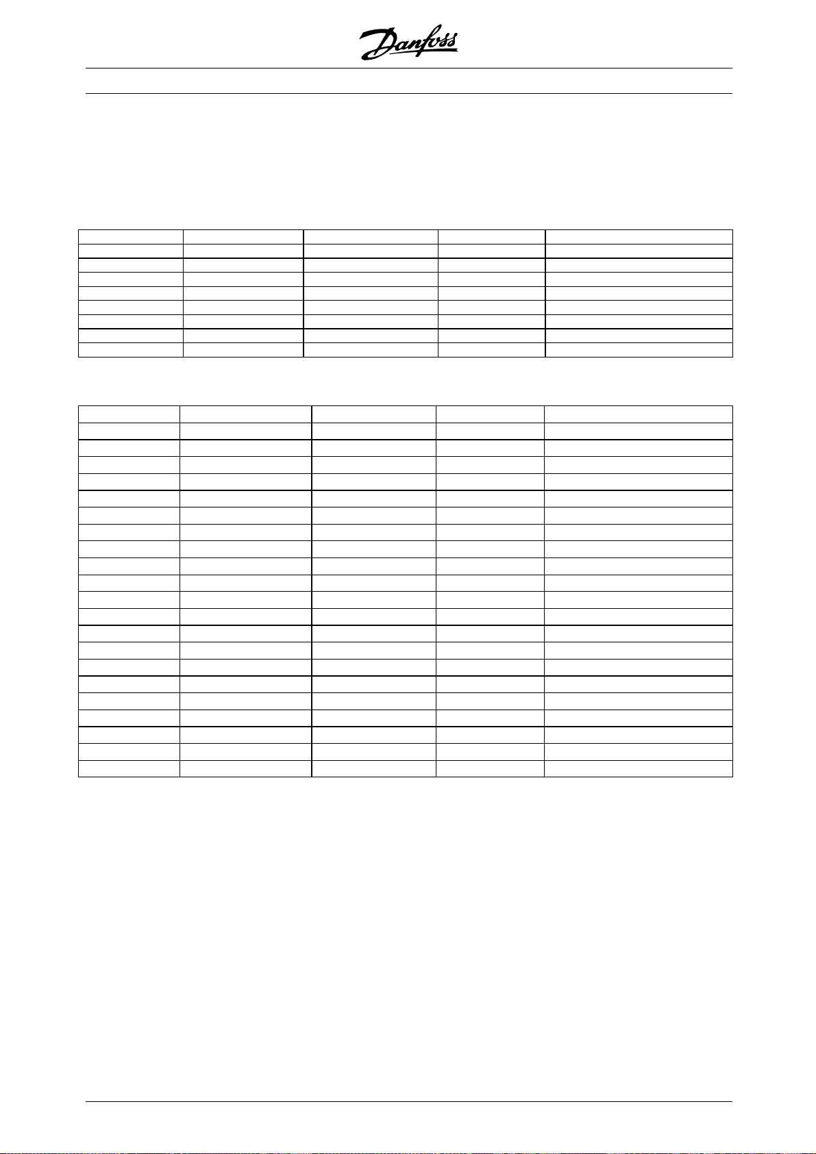
VLT®8000 AQUA
■Fuses
UL compliance
To comply with UL/cUL approvals, pre-fuses according to the table below must be used.
200-240 V
VLT Bussmann SIBA Littel fuse Ferraz-Shawmut
8006 KTN-R30 5017906-032 KLN-R30 ATM-R30 or A2K-30R
8008 KTN-R50 5012406-050 KLN-R50 A2K-50R
8011, 8016 KTN-R60 5014006-063 KLN-R60 A2K-60R
8022 KTN-R80 5014006-080 KLN-R80 A2K-80R
8027, 8032 KTN-R125 2028220-125 KLN-R125 A2K-125R
8042 FWX-150 2028220-150 L25S-150 A25X-150
8052 FWX-200 2028220-200 L25S-200 A25X-200
8062 FWX-250 2028220-250 L25S-250 A25X-250
380-480 V
VLT Bussmann SIBA Littel fuse Ferraz-Shawmu
8006 KTS-R20 5017906-020 KLS-R20 ATM-R20 or A6K-20R
8008 KTS-R25 5017906-025 KLS-R25 ATM-R25 or A6K-25R
8011 KTS-R30 5012406-032 KLS-R30 ATM-R30 or A6
8016, 8022 KTS-R40 5014006-040 KLS-R40 A6K-40R
8027 KTS-R50 5014006-050 KLS-R50 A6K-50R
8032 KTS-R60 5014006-063 KLS-R60 A6K-60R
8042 KTS-R80 2028220-100 KLS-R80 A6K-80R
8052 KTS-R100 2028220-125 KLS-R100 A6K-100R
00
700
900
5
0
KLS-R125 A6K-125R
L50S-250 A50-P250
L50S-400 A50-P400
6,9URD31
6,9URD33
8062 KTS-R125 2028220-12
8072 KTS-R150 2028220-160 KLS-R150 A6K-150R
8102 FWH-220 2028220-200 L50S-225 A50-P225
8122 FWH-250 2028220-25
8152* FWH-300/170M3017 2028220-315 L50S-300 A50-P300
8202* FWH-350/170M3018 2028220-315 L50S-350 A50-P350
8252* FWH-400/1
8302* FWH-500/170M4014 206xx32-500 L50S-500 A50-P500
8352* FWH-600/170M4016 206xx32-600 L50S-600 A50-P600
8452 170M4017 20610328502 170M6013 2063032-900 6,9URD33D08A0900
8602 170M6013 2063032-900 6,9URD33D08A0900
8652 170M6013 2063032-
70M4012
206xx32-4
t
K-30R
D08A0700
D08A0900
* Circuit Breakers manufactured by General Electric, Cat. No. SKHA36AT0800 with the rating plug listed
below can be used to meet UL requirement.
8152 rating plug No. SRPK800 A 300
8202 rating plug No. SRPK800 A 400
8252 rating plug No. SRPK800 A 400
8302 rating plug No. SRPK800 A 500
8352 rating plug No. SRPK800 A 600
48
MG.83.A2.02 - VLT is a registered Danfoss trademark
Page 49

VLT®8000 AQUA
525-600 V
Bussmann SIBA Littel fuse Ferraz-Shawmut
8002 KTS-R3 5017906-004 KLS-R003 A6K-3R
8003 KTS-R4 5017906-004 KLS-R004 A6K-4R
8004 KTS-R5 5017906-005 KLS-R005 A6K-5R
8005 KTS-R6 5017906-006 KLS-R006 A6K-6R
8006 KTS-R8 5017906-008 KLS-R008 A6K-8R
8008 KTS-R10 5017906-010 KLS-R010 A6K-10R
8011 KTS-R15 5017906-016 KLS-R015 A6K-15R
8016 KTS-R20 5017906-020 KLS-R020 A6K-20R
8022 KTS-R30 5017906-030 KLS-R030 A6K-30R
8027 KTS-R35 5014006-040 KLS-R035 A6K-35R
8032 KTS-R45 5014006-050 KLS-R045 A6K-45R
8042 KTS-R60 5014006-063 KLS-R060 A6K-60R
8052 KTS-R75 5014006-080 KLS-R075 A6K-80R
8062 KTS-R90 5014006-100 KLS-R090 A6K-90R
8072 KTS-R100 5014006-100 KLS-R100 A6K-100R
00 V (UL) and 525-690 V (CE) drives
525-6
Bussmann SIBA FERRAZ-SHAWMUT
8052 170M3013 2061032,125 6.6URD30D08A0125
8062 170M3014 2061032,16 6.6URD30D08A0160
8072 170M3015 2061032,2 6.6URD30D08A0200
8102 170M3015 2061032,2 6.6URD30D08A0200
8122 170M3016 2061032,25 6.6URD30D08A0250
8152 170M3017 2061032,315 6.6URD30D08A0315
8202 170M3018 2061032,35 6.6URD30D08A0350
8252 170M4011 2061032,35 6.6URD30D08A0350
8302 170M4012 2061032,4 6.6URD30D08A0400
8352 170M4014 2061032,5 6.6URD30D08A0500
8402 170M5011 2062032,55 6.6URD32D08A550
8502 170M4017 2061032-700 6,9URD31D08A0700
8602 170M6013 2063032-900 6,9URD33D08A0900
8652 170M6013 2063032-900 6,9URD33D08A0900
Installation
KTS-fuses from Bussmann may substitute KTN for 240 V drives.
FWH-fuses from Bussmann may substitute FWX for 240 V drives.
KLSR fuses from LITTEL FUSE may substitute KLNR fuses for 240 V drives.
L50S fuses from LITTEL FUSE may substitute L25S fuses for 240 V drives.
A6KR fuses from FERRAZ SHAWMUT may substitute A2KR for 240 V drives.
A50X fuses from FERRAZ SHAWMUT may substitute A25X for 240 V drives.
MG.83.A2.02 - VLT is a registered Danfoss trademark
49
Page 50

VLT®8000 AQUA
NonULcompliance
If UL/cUL is not to be complied with, we recommend the above mentioned fuses or:
VLT 8006-8032 200-240 V type gG
VLT 8042-8062 200-240 V type gR
VLT 8006-8072 380-480 V type gG
VLT 8102-8122 380-480 V type gR
VLT 8152-8352 380-480 V type gG
VLT 8452-8652 380-480 V type gR
VLT 8002-8072 525-600 V type gG
Not following the recommendation may result
in damage of the drive in case of malfunction.
Fuses must be designed for protection in a circuit
capable of supplying a maximum of 100000 A
(symmetrical), 500 V /600 V maximum.
rms
50
MG.83.A2.02 - VLT is a registered Danfoss trademark
Page 51

VLT®8000 AQUA
■Mechanical dimensions
All the below listed measurements are in mm/in
VLT type A B C a b aa/bb Type
IP 00/Chassis 200 - 240 V
8042 - 8062 800/31.5 370/14.6 335/13.2 780/30.7 270/10.6 225/8.9 B
IP 00 380 - 480 V
8152 - 8202 1046/41.2 408/16.1 373/14.7
8252 - 8352 1327/52.2 408/16.1 373/14.7
8452 - 8652 1547/60.9 585/23.0 494/19.4
IP 00 525 - 690 V
8052 - 8202 1046/41.1 408/16 373
8252 - 8402 1327/52.2 408/16 3731)14.7 1282/50.4 304/12 225/8.7 J
8502 - 8652 1547/60.9 585/23.0 494/19.4
IP 20/NEMA 1 200 - 240 V
8006 - 8011 560/22.0 242/9.5 260/10.2 540/21.3 200/7.9 200/7.9 D
8016 - 8022 700/27.6 242/9.5 260/10.2 680/26.8 200/7.9 200/7.9 D
8027 - 8032 800/31.5 308/12.1 296/11.7 780/30.7 270/10.6 200/7.9 D
8042 - 8062 954/37.6 370/14.6 335/13.2 780/30.7 270/10.6 225/8.9 E
IP 20/NEMA 1 380 - 480 V
8006 - 8011 395/15.6 220/8.7 200/7.9 384/15.1 200/7.9 100/3.9 C
8016 - 8027 560/22.0 242/9.5 260/10.2 540/21.3 200/7.9 200/7.9 D
8032 - 8042 70027.6 242/9.5 260/10.2 680/26.8 200/7.9 200/7.9 D
8052 - 8072 800/31.5 308/12.1 296/11.7 780/30.7 270/10.6 200/7.9 D
8102 - 8122 800/31.5 370/14.6 335/13.2 780/30.7 330/13.0 225/8.9 D
IP 21/NEMA 1 380-480 V
8152 - 8202 1208/47.5 420/16.5 373/14.7
8252 - 8352 1588/62.5 420/16.5 373/14.7
8452 - 8652 2000/78.7 600/23.6 494/19.4
IP 20/NEMA 1 525 - 690 V
8002 - 8011 395/15.55 220/8.66 200/7.87 384/15.12 200/7.87 100/3.94 C
8016 - 8027 560/22.05 242/9.53 260/10.23 540/21.26 200/7.87 200/7.87 D
8032 - 8042 700/27.56 242/9.53 260/10.23 680/26.77 200/7.87 200/7.87 D
8052 - 8072 800/31.50 308/12.13 296/11.65 780/30.71 270/10.63 200/7.87 D
IP 21/NEMA 1 525 - 690 V
8052 - 8202 1208/47.5 420/16.5 3731)/14.7 1154/45.4 304/12 225/8.7 J
8252 - 8402 1588/62.5 420/16.5 3731)/14.7 1535/60.4 304712 225/8.7 J
8502 - 8652 2000/78.7 600/23.6 494/19.4
IP 54/NEMA 12 200 - 240 V A B C D a b aa/bb Type
8006 - 8011 810/31.9 350/13.8 280/11.0 70/2.8 560/22.0 326/12.8 200/7.9 F
8016 - 8032 940/37.0 400/15.7 280/11.0 70/2.8 690/27.2 375/14.8 200/7.9 F
8042 - 8062 937/36.9 495/9.5 421/16.6 - 830/32.7 374/14.8 225/8.9 G
IP 54/NEMA 12 380 - 480 V
8006 - 8011 530/20.9 282/11.1 195/7.7 85/3.3 330/13.0 258/10.2 100/3.9 F
8016 - 8032 810/31.9 350/13.8 280/11.0 70/2.8 560/22.0 326/12.8 200/7.9 F
8042 - 8072 940/37.0 400/15.7 280/11.0 70/2.8 690/27.2 375/14.8 200/7.9 F
8102 - 8122 940/37.0 400/15.7 360/14.2 70/2.8 690/27.2 375/14.8 225/8.9 F
8152 - 8202 1208/47.5 420/16.3 373/14.71)- 1154/45.4 304/12.0 225/8.9 J
8252 - 8352 1588/62.5 420/16.3 373/14.71)- 1535/60.4 304/12.0 225/8.9 J
8452 - 8652 2000/78.7 600/23.6 494/19.4
IP 54/NEMA 12 525 - 690 V
8052 - 8202 1208/47.5 420/16.5 373
8252 - 8402 1588/62.5 420/16.5 3731)/14.7 1535/60.4 304/12 225/8.7 J
8502 - 8652 2000/78.7 600/23.6 494/19.4
1)
1001/39.4 304/12.0 225/8.9 J
1)
1282/50.5 304/12.0 225/8.9 J
1)
1502/59.1 304/12.0 225/8.9 (aa) I
1)
/14.7 1001/39.4 304/12 225/8.7 J
1)
1502/59.1 304/12.0 225/8.9 (aa) I
1)
1154/45.4 304/12.0 225/8.9 J
1)
1535/60.4 304/12.0 225/8.9 J
1)
1)
1)
1)
14.7 1154/45.4 304/12 225/8.7 J
1)
- - 225/8.9 (aa) H
- - 225/8.9 (aa) H
- - 225/8.9 (aa) H
- - 225/8.9 (aa) H
Installation
1. With disconnect add 44 mm/1.7 in
MG.83.A2.02 - VLT is a registered Danfoss trademark
aa: Minimum space above enclosure
bb: Minimum space below enclosure
51
Page 52

■Mechanical dimensions
VLT®8000 AQUA
52
MG.83.A2.02 - VLT is a registered Danfoss trademark
Page 53

■Mechanical dimensions (cont.)
Type H, IP 20, IP 54
VLT®8000 AQUA
Type I, IP 00
Type J, IP 00, IP 21, IP 54
Installation
MG.83.A2.02 - VLT is a registered Danfoss trademark
53
Page 54

■Mechanical installation
VLT®8000 AQUA
Please pay attention to the requirements
that apply to integration and field mounting
kit, see the below list. The information given
in the list must be observed to avoid serious damage
or injury, especially when installing large units.
The frequency converter must be installed vertically.
The frequency converter is cooled by means of air
circulation. For the unit to be able to release its cooling
air, the minimum distance over and below the unit
must be as shown in the illustration below.
To protect the unit from overheating, it must be ensured
that the ambient temperature does not rise above the
max. temperature stated for the frequency converter
and that the 24-hour average temperature is not
exceeded. The max. temperature and 24-hour average
can be seen from the General Technical Data.
If the ambient temperature is in the range of 45°C -55°
C, derating of the frequency converter will become
relevant, see Derating for ambient temperature.
The service life of the frequency converter will
be reduced if derating for ambient temperature
is not taken into account.
■Installation of VLT 8006-8652
All frequency converters must be installed in a
way that ensures proper cooling.
Cooling
All units require a minimum space above and
below the enclosure.
Side by side/flange by flange
All frequency converters can be mounted side
by side/flange by flange.
d [mm/in] Comments
Compact (all enclosure types)
VLT 8006-8011,
VLT 8002-8011, 525-600 V 100/3.9
VLT 8006-8032, 20
VLT 8016-8072 380-480 V 200/7.9
VLT 8102-8122 380-480 V 225/8.9
VLT 8016-8072 525-600 V 200/7.9
VLT 8042-8062, 200-240 V 225/8.9
VLT 8152-8352, 380-480 V 225/8.9
VLT 8052-8402, 525-690 V 225/8.9
VLT 8452-8652, 380-480 V
VLT 8502-8652, 525-690 V
380-480 V
0-240 V
100/3.9
200/7.9
225/8.9 IP 00: Above and below enclosure.
Installation on a plane, vertical surface (no spacers)
Installation on a plane, vertical surface (no spacers)
Installation on a plane, vertical surface (no spacers)
IP 54 filter mats must be changed when they are dirty.
IP 21/54: Only above enclosure
54
MG.83.A2.02 - VLT is a registered Danfoss trademark
Page 55

VLT®8000 AQUA
■Installation of VLT 8452-8652 380-480 V and
VLT 8502-8652, 525-690 V
Compact IP 00/Chassis, IP 21/NEMA 1
and IP 54/NEMA 12
Cooling Side-by-side
Installation
All units in the above-mentioned series require
a minimum space of 225 mm (8.9 in) above the
enclosure and must be installed on a plane floor. This
applies to IP 21/NEMA 1 and IP 54/NEMA 12 units.
Gaining access requires a minimum space of 579
mm (22.8 in) in front of the frequency converter.
All IP 21/NEMA 1 and IP 54/NEMA 12 units in the
above-mentioned series can be installed side by side
without any space between them, since these units
do not require cooling on the sides.
MG.83.A2.02 - VLT is a registered Danfoss trademark
55
Page 56

VLT®8000 AQUA
■General information about electrical installation
■High voltage warning
The voltage of the frequency converter
is dangerous whenever the equipment is
connected to mains. Incorrect installation
of the motor or the frequency converter may cause
damage to the equipment, serious personal injury
or death. Consequently, the instructions in these
Operating Instructions, as well as national and
local safety regulations, must be complied with.
Touching the electrical parts may be fatal - even
after disconnection from mains:
Using VLT 8006-8062, 200-240 V wait at
least 15 minutes
Using VLT 8006-8072, 380-480 V wait at
least 15 minutes
Using VLT 8102-8352, 380-480 V wait at
least 20 minutes
Using VLT 8452-8652, 380-480 V wait at
least 40 minutes
Using VLT 8002-8006, 525-600 V wait at least4 minutes
Using VLT 8008-8027, 525-600 V wait at
least 15 minutes
Using VLT 8032-8302, 525-600 V wait at
least 30 minutes
Using VLT 8052-8402, 525-690 V wait at
least 20 minutes
Using VLT 8502-8652, 525-690 V wait at
least 30 minutes
NB!:
It is the user’s or certified electrician’s
responsibility to ensure correct earthing and
protection in accordance with applicable
national and local norms and standards.
■Earthing
The following basic issues need to be considered
when installing a frequency converter, so as to o
btain
electromagnetic compatibility (EMC).
• Safety earthing: Please note that the frequency
converter has a high leakage current and must
be earthed appropriately for safety reas
ons.
Apply local safety regulations.
• High-frequency earthing: Keep the earth wire
connections as short as possible.
Connect the different earth systems at the lowest
possible conductor impedance. The lowest possible
conductor impedance is obtained by keeping the
conductor as short as possible and by using the
greatest possible surface area. A flat conductor, for
example, has a lower HF impedance than a round
conductor for the same conductor cross-section
. If more than one device is installed in cabinets,
C
VESS
the cabinet rear plate, which must be made of
metal, should be used as a common earth reference
plate. The metal cabinets of the different devices
are mounted on the cabinet rear plate using the
lowest possible HF impedance. This avoids having
different HF voltages for the individual devices and
avoids the risk of radio interference currents running
in connection cables that may be used between
the devices. The radio interference will have been
reduced. In order to obtain a low HF impedance, use
the fastening bolts of the devices as HF connection
to the rear plate. It is necessary to remove insulating
paint or similar from the fastening points.
■Cables
Control cables and the filtered mains cable should
be installed separate from the motor cables so
as to avoid interference overcoupling. Normally, a
distance of 204mm (8 in) will be sufficient, but it is
recommended to keep the greatest possible distance
wherever possible, especially where cables are installed
in parallel over a substantial distance.
With respect to sensitive signal cables, such as
telephone cables and data cables, the greatest
possible distance is recommended with a minimum
of 1m (3 ft) per 5m (15 ft) of power cable (mains
and motor cable). It must be pointed out that the
necessary distance depends on the sensitivity of the
installation and the signal cables, and that therefore
no precise values can be stated.
If cable jaws are used, sensitive signal cables
are not to be placed in the same cable jaws as
the motor cable or brake cable.
If signal cables are to cross power cables, this should
be done at an angle of 90 degrees.
Remember that all interference-filled in- or
outgoing cables to/from a cabinet should be
screened/armoured or filtered.
■Screened/armoured cables
The screen must be a low HF-impedance screen.
This is ensured by using a braided screen of
copper, aluminium or iron. Screen armour intended
for mechanical protection, for example, is not
suitable for an EMC-correct installation. See
also Use of EMC-correct cables.
56
MG.83.A2.02 - VLT is a registered Danfoss trademark
Page 57

■Extra protection with regard to indirect contact
ELCB relays, multiple protective earthing or earthing can
be used as extra protection, provided that local safety
regulations are complied with. In the case of an earth
fault, a DC content may develop in the faulty current.
Never use ELCB relays, type A, since such relays
are not suitable for DC fault currents.
If ELCB relays are used, this must be:
• Suitable for protecting equipment with a direct
current content (DC) in the faulty current
(3-phase bridge rectifier)
• Suitable for power-up with short charging
current to earth
• Suitable for a high leakage current
VLT®8000 AQUA
Installation
MG.83.A2.02 - VLT is a registered Danfoss trademark
57
Page 58

■RFI switch
ains supply isolated from earth:
M
If the frequency converter is supplied from an isolated
mains source ( IT mains) or TT/TN-S mains with
grounded leg, the RFI switch is recommended to
1)
be turned off (OFF)
. For further reference, see
IEC 364-3. In case optimum EMC performance is
needed, parallel motors are connected or the motor
cable length is above 25 m, it is recommended
to set the switch in ON position.
In OFF position, the internal RFI capacities (filter
capacitors) between the chassis and the intermediate
circuit are cut off to avoid damage to the intermediate
circuit and to reduce the earth capacity currents
(according to IEC 61800-3).
Please also refer to the application note VLT on
IT mains, MN.90.CX.02. It is important to use
isolation monitors that are capable for use together
with power electronics (IEC 61557-8).
NB!:
The RFI switch is not to be operated with
mains connected to the unit. Check that
the mains supply has been disconnected
before operating the RFI switch.
VLT®8000 AQUA
Position of RFI switches
Compact IP 20/NEMA 1
VLT 8006 - 8011 380 - 480 V
VLT 8002 - 8011 525 - 600 V
NB!:
Open RFI switch is only allowed at factory
set switching frequencies.
NB!:
The RFI switch connects the capacitors
galvanically to earth.
The red switches are operated by means of e.g. a
screwdriver. They are set in the OFF position when
they are pulled out and in ON position when they
are pushed in. Factory setting is ON.
Mains supply connected to earth:
The RFI switch must be in ON position in order for the
frequency converter to comply with the EMC standard.
1) Not possible with VLT 8052-8652, 525-690 V.
Compact IP 20/NEMA 1
VLT 8016 - 8027 380 - 480 V
VLT 8006 - 8011 200 - 240 V
VLT 8016 - 8027 525 - 600 V
58
Compact IP 20/NEMA 1
VLT 8032 - 8042 380 - 480 V
VLT 8016 - 8022 200 - 240 V
VLT 8032 - 8042 525 - 600 V
MG.83.A2.02 - VLT is a registered Danfoss trademark
Page 59

VLT®8000 AQUA
Compact IP 20/NEMA 1
VLT 8052 - 8122 380 - 480 V
VLT 8027 - 8032 200 - 240 V
VLT 8052 - 8072 525 - 600 V
Compact IP 54/NEMA 12
VLT 8006 - 8011 380 - 480 V
Installation
Compact IP 54/NEMA 12
VLT 8016 - 8032 380 - 480 V
VLT 8006 - 8011 200 - 240 V
Compact IP 54/NEMA 12
VLT 8102 - 8122 380 - 480 V
MG.83.A2.02 - VLT is a registered Danfoss trademark
Compact IP 54/NEMA 12
VLT 8042 - 8072 380 - 480 V
VLT 8016 - 8032 200 - 240 V
59
Page 60
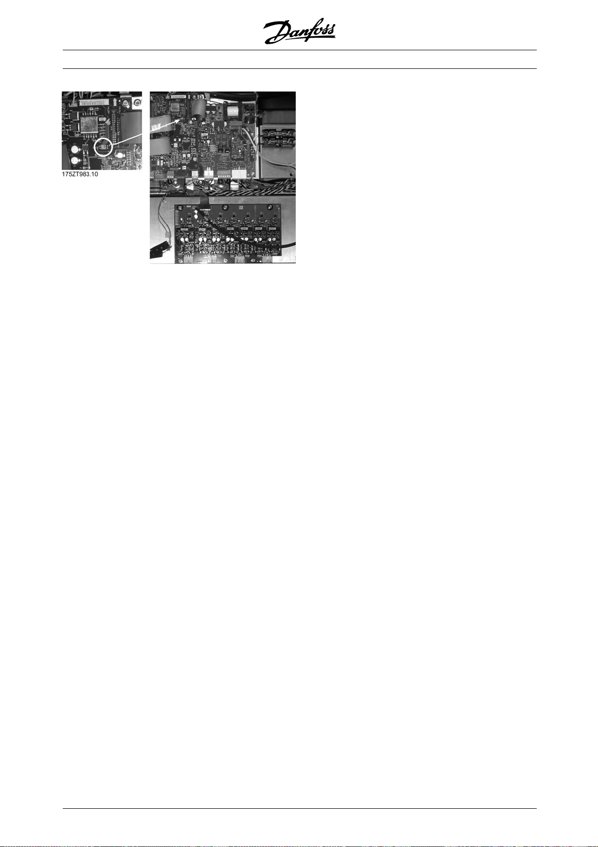
All enclosure types
VLT 8152-8652 380 - 480 V
VLT®8000 AQUA
60
MG.83.A2.02 - VLT is a registered Danfoss trademark
Page 61

■High voltage test
A high voltage test can be carried out by short-circuiting
terminalsU,V,W,L
and L3and energizing
1,L2
by max. 2.5 kV DC for one second between
this short-circuit and the chassis.
NB!:
The RFI switch must be closed (position
ON) when high voltage tests are carried out.
The mains and motor connection must be
interrupted in the case of high voltage tests of the total
installation if the leakage currents are too high.
■Heat emission from VLT 8000 AQUA
The tables in General technical data show the
power loss P
maximum cooling air temperature t
(W) from VLT 8000 AQUA. The
ϕ
IN, MAX
is 40° C
(104° F) at 100% load (of rated value).
VLT®8000 AQUA
■Ventilation of integrated VLT 8000 AQUA
The quantity of air required for cooling frequency
converter can be calculated as follows:
1. Add up the values of P for all the frequency
converters to be integrated in the same panel.
The highest cooling air temperature (t
must be lower than t
IN, MAX
40° C (104° F).
)present
IN
The day/night average must be 5°C (9° F) lower.
The outlet temperature of the cooling air must
not exceed: t
OUT, MAX
45° C (113° F).
2. Calculate the permissible difference between
the temperature of the cooling air (t
its outlet temperature (t
OUT
):
)and
IN
t= 45° C (113° F) -tIN.
3. Calculate the required
Insert tinKelvin
The outlet from the ventilation must be placed above
the highest-mounted frequency converter.
Allowancemustbemadeforthepressureloss
across the filters and for the fact that the pressure
is going to drop as the filters are choked.
Installation
MG.83.A2.02 - VLT is a registered Danfoss trademark
61
Page 62

VLT®8000 AQUA
■EMC-correct electrical installation
525-600 V units do not comply with European
EMC and Low Voltage Directives.
The following is a guideline to good engineering
practice, when installing drives. Following these
guidelines is advised, where compliance with EN 50081,
EN 55011 or EN 61800-3 First environment is required.
If the installation is in EN 61800-3 Second environment,
then it is acceptable to deviate from these guidelines. It
is however not recommended. See also CE labelling,
Emission and EMC test results in this manual.
ood engineering practice to ensure EMC-correct
G
electrical installation:
• Use only braided screened/armoured motor cables
and braided screened/armoured control cables. The
screen should provide a minimum coverage of 80%.
The screen material must be metal, not limited to
but typically copper, aluminium, steel or lead. There
are no special requirements for the mains cable.
• Installations using rigid metal conduits are not
required to use screened cable, but the motor
cable must be installed in conduit separate from
the control and mains cables. Full connection
of the conduit from the drive to the motor is
required. The EMC performance of flexible
conduits varies a lot and information from the
manufacturer must be obtained.
• Connect the screen/armour/conduit to earth
at both ends for motor cables as well as for
control cables. See also Earthing of braided
screened/armoured control cables.
• Avoid terminating the screen/armour with
twisted ends (pigtails). Such a termination
increases the high frequency impedance of the
screen, which reduces its effectiveness at high
frequencies. Use low impedance cable clamps
or EMC cable glands instead.
• It is important to have good electrical contact
between the mounting plate on which the frequency
converter is installed and the metal chassis of
the frequency converter unit.
Exception:
- IP54/NEMA 12 units designed for wall mounting
- VLT 8042-8062 (200-240 V) IP20/NEMA 1
- VLT 8152-8652 (380-480 V) IP20/NEMA 1
- VLT 8152-8652 (525-690 V) IP20/NEMA 1
connections for IP00/Chassis and IP20/NEMA
1 installations.
• Avoid using unscreened/unarmoured motor or
control cables inside cabinets housing the drive(s),
whenever this can be avoided.
• An uninterrupted high frequency connection
between the frequency converter and the motor
is required for IP54/NEMA 12 units.
The next illustration shows an example of an
EMC-correct electrical installation of an IP 20/NEMA
1 frequency converter; the frequency converter has
been installed in a cabinet (enclosure) together with
an output contactor and is connected to a PLC
which, in this example, is installed in a separate
cabinet. For IP 54/NEMA 12 units, VLT 8152-8652
(380-480 V) and VLT 8042-8062 (200-240 V) units
in IP20/NEMA 1 enclosures; screened cables are
connected by using EMC conduits to assure proper
EMC performance. (See next illustration.)
Other ways of making the installation may give as
good an EMC performance, provided the above
engineering practice guidelines are followed.
Please note, that when the installation is not made
according to these guidelines as well as when
unscreened cables and control wires are used, some
emission requirements are not complied with, although
the immunity requirements are fulfilled.
This however does not apply to IP54/NEMA 12
units as they are designed for wall mounting and
VLT 8152-8600, 380-480 VAC and VLT 8042-8062,
200-240 VAC in IP20/NEMA 1 enclosure.
• Use starwashers and galvanically conductive
installation plates to secure good electrical
62
MG.83.A2.02 - VLT is a registered Danfoss trademark
Page 63

VLT®8000 AQUA
Installation
MG.83.A2.02 - VLT is a registered Danfoss trademark
63
Page 64

■Earthing/Grounding of screened/armoured
control cables
Generally speaking, control cables must be screened/
armoured and the screen must be connected
by means of a cable clamp at both ends to
the metal cabinet of the unit.
The drawing below indicates how correct
earthing/grounding is carried out.
VLT®8000 AQUA
Correct earthing/grounding
Control cables and cables for serial communication
must be fitted with cable clamps at both ends to
ensure the best possible electrical contact.
rong earthing/grounding
W
Do not use twisted cable ends (pigtails), since these
increase the screen impedance at high frequencies.
rotection with respect to earth potential
P
between PLC and frequency converter
If the earth potential between the frequency converter
and the PLC (etc.) is different, electric noise may
occur that will disturb the whole system. This
problem can be solved by fitting an equalizing
cable, to be placed next to the control cable.
Minimum cable cross-section: 8 AWG.
or 50/60 Hz earth loops
F
If very long control cables are used, 50/60 Hz
earth loopsmay occur that will disturb the whole
system. This problem can be solved by connecting
one end of the screen to via an earth 100nF
capacitor (keeping leads short).
ables for serial communication
C
Low-frequency noise currents between two frequency
converter can be eliminated by connecting one end of
the screen to terminal 61. This terminal is connected
to earth via an internal RC link. It is recommended
to use twisted-pair cables to reduce the differential
mode interference between the conductors.
64
MG.83.A2.02 - VLT is a registered Danfoss trademark
Page 65

■Electrical installation, enclosures
Compact IP 54/NEMA 12
VLT 8006-8011, 380-480 V
VLT®8000 AQUA
Compact IP 20/NEMA 1
VLT 8006-8011, 380-480 V
VLT 8002-8011, 525-600 V
Installation
Compact IP 20/NEMA 1
VLT 8006-8032, 200-240 V
VLT 8016-8072, 380-480 V
VLT 8016-8072, 525-600 V
MG.83.A2.02 - VLT is a registered Danfoss trademark
65
Page 66

VLT®8000 AQUA
Compact IP 00/Chassis
VLT 8042-8062, 200-240 V
Compact IP 54/NEMA 12
VLT 8006-8032, 200-240 V
VLT 8016-8072, 380-480 V
Compact IP 54/NEMA 12
VLT 8042-8062, 200-240 V
Compact IP 20/NEMA 1
VLT 8042-8062, 200-240 V
66
MG.83.A2.02 - VLT is a registered Danfoss trademark
Page 67

Compact IP 20/NEMA 1
VLT 8102-8122, 380-480 V
VLT®8000 AQUA
IP 54/NEMA 12, IP 21/NEMA 1
VLT 8152-8202, 380-480 V
VLT 8052-8202, 525-690 V
Installation
Compact IP 54/NEMA 12
VLT 8102-8122, 380-480 V
MG.83.A2.02 - VLT is a registered Danfoss trademark
IP 00/Chassis
VLT 8152-8202, 380-480 V
VLT 8052-8202, 525-690 V
Note: The RFI switch has no function in
the 525-690 V drives.
67
Page 68

VLT®8000 AQUA
■Electrical installation, power cables
IP 20/NEMA 1
VLT 8006-8032, 200-240 V
VLT 8016-8122, 380-480 V
VLT 8016-8072, 525-600 V
IP 54/NEMA 12, IP 21/NEMA 1 with disconnect
and main fuse
VLT 8252-8352, 380-480 V
VLT 8252-8402, 525-690 V
IP 00/Chassis with disconnect and main fuse
VLT 8252-8352, 380-480 V
VLT 8252-8402, 525-690 V
Note: The RFI switch has no function in
the 525-690 V drives.
68
MG.83.A2.02 - VLT is a registered Danfoss trademark
Page 69

Compact IP 20/NEMA 1, and IP 54/NEMA 12
VLT 8006-8011, 380-480 V
VLT 8002-8011, 525-600 V
VLT®8000 AQUA
Installation
IP 54/NEMA 12
VLT 8006-8032, 200-240 V
VLT 8016-8072, 380-480 V
MG.83.A2.02 - VLT is a registered Danfoss trademark
69
Page 70

■Electrical installation, power cables
IP 00/Chassis and IP 20/NEMA 1
VLT 8042-8062, 200-240 V
VLT®8000 AQUA
IP 54/NEMA 12
VLT 8042-8062, 200-240 V
Compact IP 54 /NEMA 12
VLT 8102-8122, 380-480 V
70
MG.83.A2.02 - VLT is a registered Danfoss trademark
Page 71

■Electrical installation, power cables
VLT®8000 AQUA
Position of earth terminals, IP 00
Compact IP 00 with disconnect and fuse
VLT 8452-8652 380-480 V and VLT
8502-8652, 525-690 V
Installation
Compact IP 00 without disc onnect and fuse
VLT 8452-8652 380-480 V and VLT
8502-8652, 525-690 V
Note: The RFI switch has no function in
the 525-690 V drives.
MG.83.A2.02 - VLT is a registered Danfoss trademark
71
Page 72

VLT®8000 AQUA
Compact IP 21 / IP 54 without disconnect and fuse
VLT 8452-8652 380-480 V and VLT
8502-8652, 525-690 V
Note: The RFI switch has no function in
the 525-690 V drives.
Position of ear th terminals, IP 21 / IP 54
72
MG.83.A2.02 - VLT is a registered Danfoss trademark
Page 73

■Use of emc-correct cables
Braided screened/armoured cables are recommended
to optimise EMC immunity of the control cables and
the EMC emission from the motor cables.
The ability of a cable to reduce the in- and outgoing
radiation of electric noise depends on the transfer
impedance (Z
). The screen of a cable is normally
T
designed to reduce the transfer of electric noise;
however, a screen with a lower transfer impedance
) value is more effective than a screen with a
(Z
T
higher transfer impedance (Z
).
T
VLT®8000 AQUA
Transfer impedance (Z
basis of the following factors:
- The conductibility of the screen material.
- The contact resistance between the individual
screen conductors.
- The screen coverage, i.e. the physical area
of the cable covered by the screen - often
stated as a percentage value.
- Screen type, i.e. braided or twisted pattern.
Aluminium-clad with copper wire.
Twisted copper wire or armoured steel wire cable.
Single-layer braided copper wire with varying percentage screen
coverage.
This is the typical Danfoss reference cable.
) can be assessed on the
T
Installation
Transfer impedance (ZT) is rarely stated by
cable manufacturers, but it is often possible to
estimate transfer impedance (Z
) by assessing
T
the physical design of the cable.
Double-layer braided copper wire.
Twin layer of braided copper wire with a magnetic,
screened/armoured intermediate layer.
Cable that runs in copper tube or steel tube.
Lead cable with 1.1 mm wall thickness.
MG.83.A2.02 - VLT is a registered Danfoss trademark
73
Page 74

VLT®8000 AQUA
■Tightening torque and screw sizes
These figures apply to the following terminals:
The table shows the torque required when fitting
terminals to the frequency converter. For VLT
Mains terminals (Nos.) L1, L2, L3
8006-8032, 200-240 V; VLT 8006-8122, 380-480
and VLT 8002-8072, 525-600 V the cables must be
fastened with screws. For VLT 8042-8062, 200-240
Motor terminals (Nos.) U, V, W
Earth terminal (Nos.) 94, 95, 99
V; VLT 8152-8652, 380-480 V and VLT 8052-8652,
525-690 V, the cables must be fastened with bolts.
VLT type
3 x 200-240 V
VLT 8006-8011 16 in-lbs/1.8 Nm (IP 20) M4
VLT 8006-8016 16 in-lbs/1.8 Nm (IP 54) M4
VLT 8016-8027 26.6 in-lbs/3.0 Nm (IP 20) M5
VLT 8022-8027 26.6 in-lbs/3.0 Nm (IP 54)
VLT 8032 53 in-lbs/6.0 Nm M6
VLT 8042-8062 100 in-lbs/11.3 Nm M8 (bolt)
VLT type
3 x 380-480 V
VLT 8006-8011 5.3 in-lbs/0.5-0.6 Nm M3
VLT 8016-8027 16 in-lbs/1.8 Nm (IP 20) M4
VLT 8016-8032 16 in-lbs/1.8 Nm (IP 54) M4
VLT 8032-8052 26.6 in-lbs/3.0 Nm (IP 20) M5
VLT 8042-8052 26.6 in-lbs/3.0 Nm (IP 54)
VLT 8062-8072 53 in-lbs/6.0 Nm M6
VLT 8102-8122 133 in-lbs/15 Nm (IP 20) M8
VLT 8152-8352 168 in-lbs/19 Nm
VLT 8452-8652 168 in-lbs/19 Nm M10 (compression lug)
VLT type
3 x 525-600 V
VLT 8002-8011 5.3 in-lbs/0.5-0.6 Nm M3
VLT 8016-8027 16 in-lbs/1.8 Nm M4
VLT 8032-8042 26.6 in-lbs/3.0 Nm
VLT 8052-8072 53 in-lbs/6.0 Nm M6
VLT type
3 x 525-690 V
VLT 8052-8402 168 in-lbs/19 Nm
VLT 8502-8652
525-690 V
Tightening-up
torque
Tightening-up
torque
213 in-lbs/24 Nm (IP 54)
4)
2)
2)
1)
Screw/bolt
size
M5
Screw/bolt
size
M5
M10 (bolt)
84 in-lbs/9.5 Nm M8 (box lug)
Tightening-up
torque
2)
4)
Screw/bolt
size
M5
M10 (bolt)
168 in-lbs/19 Nm M10 (compression lug)
84 in-lbs/9.5 Nm M8 (box lug)
91, 92, 93
96, 97, 98
To ol
3)
3)
3)
4mm
4mm
5mm
To ol
3)
3)
3)
3)
4mm
4mm
5mm
6mm
8mm
5)
5)
5)
16 mm
16 mm
13 mm
To ol
3)
3)
5)
5)
5)
4mm
5mm
16 mm
16 mm
13 mm
1. Loadsharing terminals 14 Nm/M6, 5 mm in Allen key
2. IP 54 units with RFI filter mains terminals 6 Nm
3. Allen screws (hexagon)
4. Loadsharing terminals 84 in-lbs/9.5 Nm/M8 (bolt)
5. Wrench
74
MG.83.A2.02 - VLT is a registered Danfoss trademark
Page 75
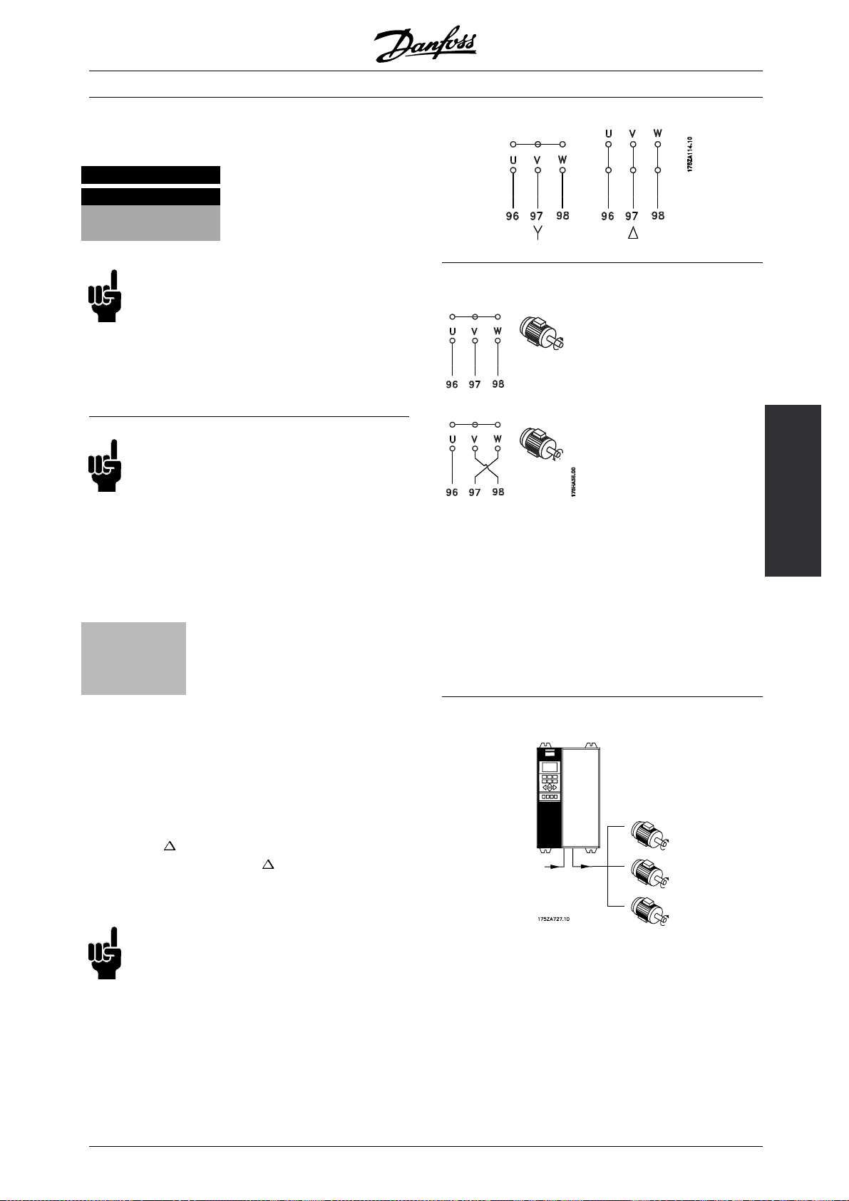
■Mains connection
Mains must be connected to terminals 91, 92, 93.
Nos. 91, 92, 93 Mains voltage 3 x 200-240 V
L1, L2, L3 Mains voltage 3 x 380-480 V
Mains voltage 3 x 525-600 V
Mains voltage 3 x 525-690 V
NB!:
Check that the mains voltage corresponds to
the mains voltage of the frequency converter,
which can be seen from the nameplate.
See Technical data for correct sizing of cable
cross-sections.
NB!:
It is the responsability of the user or installer
to ensure that proper earthing, branch
circuit, and motor overload protection is
in accordance with national and local electrical
and safety regulations and codes.
■Motor connection
The motor must be connected to terminals 96,
97, 98. Earth to terminal 94/95/99.
Nos.
96. 97. 98
U, V, W
No. 94/95/99 Earth connection
Motor voltage 0-100 % of mains voltage
VLT®8000 AQUA
■Direction of IEC motor rotation
The factory setting is for clockwise rotationwith the VLT
frequency transformer output connected as follows.
Terminal 96 connected to U-phase
Terminal 97 connected to V-phase
Terminal 98 connected to W-phase
The direction of rotation can be changed by switching
two phases in the motor cable.
Installation
See Technical data for correct sizing of cable
cross-sections.
All types of three-phase asynchronous standard motors
can be used with a VLT 8000 AQUA unit.
Small-size motors are normally star-connected.
(220/380 V,
delta-connected (380/660 V,
/Y). Large-size motors are
/Y). The correct
connection and voltage can be read from
the motor nameplate.
NB!:
In older motors without phase coil insulation,
a LC filter should be fitted to the frequency
converter output.
■Parallel coupling of motors
VLT 8000 AQUA is able to control several motors
connected in parallel. If the motors are to have different
rpmvalues,themotorsmusthavedifferentrated
rpm values. Motor rpm is changed simultaneously,
which means that the ratio between the rated rpm
values is maintained across the range.
The total current consumption of the motors is
not to exceed the maximum rated output current
for the frequency converter.
I
VLT,N
MG.83.A2.02 - VLT is a registered Danfoss trademark
75
Page 76

VLT®8000 AQUA
Problems may arise at the start and at low rpm values if
the motor sizes are widely different. This is because the
relatively high ohmic resistance in small motors calls for
a higher voltage at the start and at low rpm values.
In systems with motors connected in parallel, the
electronic thermal relay (ETR) of the frequency
converter cannot be used as motor protection for
the individual motor. Consequently, additional motor
protection is required, such as thermistors in earth
motor (or individual thermal relays).
NB!:
Parameter 107 Automatic Motor Adaptation,
AMA and Automatic Energy Optimization, AEO
in parameter 101 Torque characteristics cannot
be used motors are connected in parallel.
■Motor cables
See Technical data for correct sizing of motor
cable cross-section and length.
Always comply with national and local regulations
on cable cross-sections.
NB!:
If an unscreened cable is used, some
EMC requirements are not complied with,
see EMC test results.
If the EMC specifications regarding emission are
to be complied with, the motor cable must be
screened, unless otherwise stated for the RFI filter
in question. It is important to keep the motor cable
as short as possible so as to reduce the noise level
and leakage currents to a minimum.
The motor cable screen must be connected to the
metal cabinet of the frequency converter and to the
metal cabinet of the motor. The screen connections
are to be made with the biggest possible surface (cable
clamp). This is enabled by different installation devices
in the different frequency converters. Mounting with
twisted screen ends (pigtails) is to be avoided, since
these spoil the screening effect at higher frequencies.
If it is necessary to break the screen to install a motor
isolator or motor contactor, the screen must be
continued at the lowest possible HF impedance.
Motor current, I
has been programmed for the rated
VLT,N
motor current (can be read from the motor nameplate).
■Earth connection
Since the leakage currents to earth may be higher
than 3.5 mA, the frequency converter must always
be earthed in accordance with applicable national
and local regulations. In order to ensure good
mechanical connection of the earth cable, its cable
cross-section must be at least 8 AWG/10mm
added security, an RCD (Residual Current Device)
may be installed. This ensures that the frequency
converter will cut out if the leakage currents get too
high. See RCD Instructions MI.66.AX.02.
■Installation of 24 Volt external DC supply
Torque: 0.5 - 0.6 Nm
Screw size:
M3
No. Function
35(-), 36 (+) 24 V External DC supply
(Available with VLT 8016-8652 380-480 V and VLT 8052-8652
525-690 V only)
24 V external DC supply can be used as low-voltage
supply to the contro
l card and any option cards
installed. This enables full operation of the LCP (incl.
parameter setting) without connection to mains.
Please note th
at a warning of low voltage will be
given when 24 V DC has been connected; however,
there will be no tripping. If 24 V external DC supply
is connect
ed or switched on at the same time as the
mainssupply,atimeofmin.200msec.mustbeset
in parameter 111, Start delay.Apre-fuseofmin.6
Amp, sl
ow-blow, can be fitted to protect the external
24 V DC supply. The power consumption is 15-50
W, depending on the load on the control card.
NB!:
e24VDCsupplyoftypePELVtoensure
Us
correct galvanic isolation (type PELV) on the
control terminals of the frequency converter.
2
.For
■Motor thermal protection
The electronic thermal relay in UL-approved frequency
converter has received UL-approval for single motor
protection, as long as parameter 117 Motor thermal
protection has been set to ETR Trip and parameter 105
76
MG.83.A2.02 - VLT is a registered Danfoss trademark
Page 77

■DC bus connection
The DC bus terminal is used for DC back-up,
with the intermediate circuit being supplied
from an external DC source.
Te rm i na l no s. Nos. 88, 89
Contact Danfoss if you require further information.
■High-voltage relay
The cable for the high-voltage relay must be connected
to terminals 01, 02, 03. The highprogrammed in parameter 323, Relay 1, output.
voltage relay is
Relay output 1
No. 1 1+3 break, 1+2 make.
Max. 240 V AC, 2 Amp.
Min. 24 V DC, 10 mA or
24 V AC, 100 mA.
Max. cross-section: 4 mm2/10 AWG.
To rq ue : 0 .5 N m/ 5 i n -l b s
Screw size: M3
VLT®8000 AQUA
Installation
■Control card
All terminals for the control cables are located under
the protective cover of the frequency converter.
The protective cover (see drawing below) can be
removed by means of a pointed object (except
IP54/NEMA 12 units) - a screwdriver or similar.
MG.83.A2.02 - VLT is a registered Danfoss trademark
77
Page 78

VLT®8000 AQUA
■Electrical installation, control cables
To rq ue : 0 .5 N m ( 5 i n- lb s)
Screw size: M3.
Generally speaking, control cables must be screened/
armoured and the screen must be connected by
means of a cable clamp at both ends to the metal
cabinet of the unit (see Earthing/Grounding of
screened (armoured control cables).
Normally, the screen must also be connected to the
body of the controlling unit (follow the instructions for
installation given for the unit in question).
If very long control cables are used, 50/60 Hz
earth loops may occur that will disturb the whole
system. This problem can be solved by connecting
one end of the screen to earth via a 100nF
capacitor (keeping leads short).
■Electrical installation, control cables
To rq u e: 0. 5 N m/ 5 i n -l b s
Screw size: M3
See Earthing/Grounding of screened (armoured control
cables for correct termination of control cables.
16-33 Digital inputs. See parameters
300-307 Digital inputs.
20 Common for digital inputs.
39 Common for analog/digital outputs.
See Examples of connection.
42, 45 Analog/digital outputs for indicating
frequency, reference, current and
torque. See parameters 319-322
Analoge/digital outputs.
50 Supply voltage to potentiometer and
thermistor 10 V DC.
53, 54 Analog voltage input, 0 - 10 V DC.
55 Common for analog inputs.
60 Analog current input 0/4-20 mA. See
parameters 314-316 Termi na l 60.
61 Termination of serial communication.
See Earthing/Grounding of screened
(armoured control cables.
This terminal is not normally to be
used.
68, 69 RS 485 interface, serial
communication. When multiple
frequency converters are connected
to a communication bus, switches 2
and 3 on control card in the first and
last units must be closed (position
ON). For the remaining frequency
converters, switches 2 and 3 must
be open (OFF). The factory setting is
closed (position ON).
No. Function
04, 05 Relay output 2 can be used for
indicating status and warnings.
12, 13 Voltage supply to digital inputs. For
he 24 V DC to be used for digital
t
inputs, switch 4 on the control card
must be closed, position "on".
78
MG.83.A2.02 - VLT is a registered Danfoss trademark
Page 79

■Switches 1-4
The dipswitch is located on the control card. It is used
for serial communication and external DC supply.
The switching position shown is the factory setting.
Switch 1 has no function.
Switches 2 and 3 are used for terminating an RS
485 interface, serial communication. In the first
and the last frequency converter, switches 2 and
3 must be ON. In the other frequency converter,
switches 2 and 3 must be OFF.
Switch 4is used if anexternal 24 V DC supply is required
for the control terminals. Switch 4 separates the
common potential for the internal 24 V DC supply from
the common potential of the external 24 V DC supply.
NB!:
Please note that when Switch 4 is in position
"OFF", theexternal 24 V DC supply is galvanically
isolated from the frequency converter.
VLT®8000 AQUA
Installation
MG.83.A2.02 - VLT is a registered Danfoss trademark
79
Page 80

VLT®8000 AQUA
■Bus connection
The serial bus connection in accordance with the RS
485 (2-conductor) norm is connected to terminals
68/69 of the frequency converter (signals P and N).
Signal P is the positive potential (TX+,RX+), while
signal N is the negative potential (TX-,RX-).
If more than one frequency converter is to be connected
to a given master, use parallel connections.
In order to avoid potential equalizing currents in the
screen, the cable screen can be earthed via terminal
61, which is connected to the frame via an RC-link.
Bus termination
The bus must be terminated by a resistor network
at both ends. For this purpose, set switches 2
and 3 on the control card for "ON".
80
MG.83.A2.02 - VLT is a registered Danfoss trademark
Page 81

■Connection example VLT 8000 AQUA
The diagram below gives an example of a typical
VLT 8000 AQUA installation.
The mains supply is connected to terminals 91 (L1),
92 (L2) and 93 (L3), while the motor is connected to
96 (U), 97 (V) and 98 (W). These numbers can also be
seen from the terminals of the frequency converter.
An external DC supply can be connected to
terminals 88 and 89.
Analog inputs can be connected to terminals 53 [V],
54 [V] and 60 [mA]. These inputs can be programmed
for either reference, feedback or thermistor. See
Analog inputs in parameter group 300.
VLT®8000 AQUA
There are 8 digital inputs, which are controlled with
24 V DC. Terminals 16-19, 27, 29, 32, 33. These
inputs can be programmed in accordance with the
table in Inputs and outputs 300-328.
There are two analog/digital outputs (terminals
42 and 45), which can be programmed to show
the present status or a process value, such as
. Relay outputs 1 and 2 can be used for
0-f
MAX
giving the present status or a warning.
On terminals 68 (P+) and 69 (N-) RS 485 interface,
the frequency converter can be controlled and
monitored via serial communication.
* These terminals can be programmed for
other functions.
Installation
MG.83.A2.02 - VLT is a registered Danfoss trademark
81
Page 82

VLT®8000 AQUA
■Connection examples
■Single-pole star t/stop
- Start/stop using terminal 18.
Parameter 302 = Start [1]
- Quick-stop using terminal 27.
Parameter 304 = Coasting stop, inverse [0]
■Digital speed up/down
■Run permissive
- Start permitted with terminal 16.
Parameter 300 = Run permissive [8].
- Start/stop with terminal 18.
Parameter 302 = Start [1].
- Quickstop with terminal 27.
Parameter 304 = Coasting stop, inverse [0].
- Activated peripheral equip
Parameter 323 = Start command active [13].
- Speed up and down using terminals 32 and 33.
Parameter 306 = Speed up [7]
Parameter 307 = Speed down [7]
Parameter 305 = Freeze reference [2]
■Potentiometer reference
-Parameter 308 = Reference [1]
Parameter 309 = Terminal 53, min. scaling
Parameter 310 = Terminal 53, max. scaling
■2-zone regulation
- Parameter 308 = Feedback [2].
- Parameter 311 = Feedback [2].
■Transmitter connection
82
- Parameter 314 = Reference [1]
- Parameter 315 = Terminal 60, min. scaling
- Parameter 316 = Terminal 60, max. scaling
MG.83.A2.02 - VLT is a registered Danfoss trademark
Page 83

■3-wire start/stop
- Stop inverse by means of terminal 32.
Parameter 306 = Stop inverse[14]
- Latched start using terminal 18.
Parameter 302 = Latched start [2]
- Jog by means of terminal 29.
Parameter 305 = Jog [12]
VLT®8000 AQUA
Installation
MG.83.A2.02 - VLT is a registered Danfoss trademark
83
Page 84
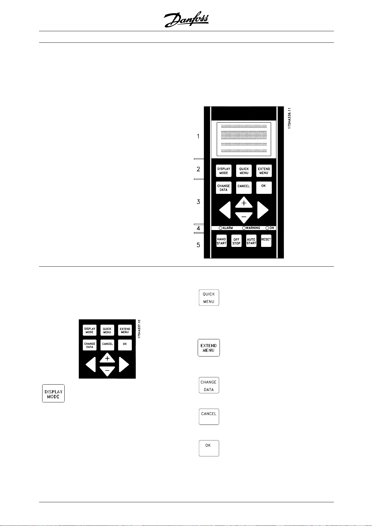
VLT®8000 AQUA
■Control unit LCP
The front of the frequency converter features
a control panel - LCP (Local Control Panel).
This is a complete interface for operation and
programming of the VLT 8000 AQUA.
The control panel is detachable and can - as an
alternative - be installed up to 3m/10 ft away from
the frequency converter, e.g. on the front panel,
by means of a mounting kit option.
The functions of the control panel can be
divided into five groups:
1. Display
2. Keys for changing display mode
3. Keys for changing program parameters
4. Indicator lamps
5. Keys for local operation.
All data are indicated by means of a 4-line
alpha-numeric display, which, in normal operation,
is able to show 4 operating data values and 3
operating condition values continuously. During
programming, all the information required for quick,
effective parameter Setup of the frequency converter
will be displayed. As a supplement to the display,
there are three indicator lamps for voltage (ON),
warning (WARNING) and alarm (ALARM), respectively.
All frequency converter parameter Setups can be
changed immediately via the control panel, unless this
function has been programmed to be Locked [1] via
parameter 016 Lock for data change or via a digital
input, parameters 300-307 Lock for data change.
■Control keys for parameter setup
The control keys are divided into functions. This means
that the keys between display and indicator lamps
are used for parameter Setup, including selecting the
display indication during normal operation.
[DISPLAY MODE] is used for selecting
theindicationmodeofthedisplayor
whenreturningtotheDisplaymode
from either the Quick menu or the
Extend menu mode.
[QUICK MENU] gives access to the
parameters used for the Quick menu.
It is possible to switch between the
Quick menu and the Extend menu
modes.
[EXTEND MENU] gives access to all
parameters. It is possible to switch
between the Extend menu and the
Quick menu modes.
[CHANGE DATA] is used for changing
a setting selected either in the Extend
menu or the Quick menu mode.
[CANCEL] is used if a change of
the selec-ted parameter is not to be
carried out.
[OK] is used for confirming a change
of the parameter selected.
84
MG.83.A2.02 - VLT is a registered Danfoss trademark
Page 85

VLT®8000 AQUA
[+/-] is used for selecting parameters
and for changing a chosen parameter.
These keys are also used to change
the local reference.
In addition, the keys are used in
Display mode to switch between
operation variable readouts.
[<>] is used when selecting a
parameter group and for moving
the cursor when changing numerical
values.
■Indicator lamps
At the bottom of the control panel is a
alarm lamp and a yellow warning lamp, as well
as a green voltage LED.
If certain threshold values are exceeded, the
alarm and/ or warning lamp is activated, and a
status or alarm text is displayed.
NB!:
The voltage indicator lamp is activated when
the frequency converter receives voltage.
■Local control
Underneath the indicator lamps are keys
for local control.
red
[HAND START] is used if the frequency
converter is to be controlled via the
control unit. The frequency converter
will start the motor, since a start
command is given by means of [HAND
START].
On the control terminals, the following
control signals will still be active when
[HAND START] is activated:
• Hand start - Off stop - Auto start
• Safety Interlock
• Reset
• Coasting stop inverse
• Reversing
• Setup select lsb - Setup select msb
• Jog
• Run permissive
• Lock for data change
• Stop command from serial
communication
NB!:
If parameter 201 Output frequency lo
issettoanoutputfrequencygreaterthan
f
MIN
0 Hz, the motor will start and ramp up to this
frequency when [HAND START]
is activated.
[OFF/STOP] is used for stopp
connected motor. Can be selected as
Enable [1] or Disable [0] via parameter
013. If the stop funct
ion is activated,
line 2 will flash.
[AUTO START] is used if the frequency
converter is to be controlled via
the control termina
ls and/or serial
communication. When a start signal is
active on the control terminals and/or
the bus, the fre
quency converter will
start.
Installation
w limit
ing the
MG.83.A2.02 - VLT is a registered Danfoss trademark
NB!:
An active HAND-OFF-AUTO signal via the digital
inputs will have higher priority than the control
keys [HAND START]-[AUTO START].
[RESET] is used for resetting the
frequency converter after an alarm
(trip). Can be selected as Enable [1]
or Disable [0] via parameter 015 Reset
on LCP.
See also List of warnings and alarms.
85
Page 86

VLT®8000 AQUA
■Display mode
In normal operation, any 4 different operating variables
can be indicated continuously: 1.1 and 1.2 and
1.3 and 2. The present operating status or alarms
and warnings that have arisen are shown in line 2
in the form of a number. In the case of alarms, the
alarm in question will be shown in lines 3 and 4,
accompanied by an explanatory note. Warnings will
flashinline2,withanexplanatorynoteinline1. In
addition, the display shows the active Setup.
The arrow indicates the direction of rotation; here the
frequency converter has an active reversing signal. The
arrow body disappears if a stop command is given or if
the output frequency falls below 0.01 Hz. The bottom
line gives the status of the frequency converter.
The scroll list on the next page gives the operating
data that can be shown for variable 2 in display mode.
Changes are made via the [+/-] keys.
1st line
2nd line
3rd line
VAR 1.1 VAR 1.2 VAR 1.3
SETUP
VAR 2
1
STATUS
4th line
OFF means that the frequency converter ignores all
control commands and stops the motor.
The centre part of the status line indicates the
refe-rence element that is active. REMOTE means
that the reference from the control terminals is active,
while LOCAL indicates that the reference is determined
via the [+/-] keys on the control panel.
The last part of the status line indicates the current
status, for example "Running", "Stop" or "Alarm".
■Display mode I
VLT 8000 AQUA offers different display modes
depending on the mode selected for the
frequency converter.
Below is a display mode, in which the frequency
195NA113.10
converter is in Auto mode with remote reference
at an output frequency of 40 Hz.
In this display mode, reference and control are
determined via the control terminals.
The text in line 1 gives the operating variable
shown in line 2.
FREQUENCY
40.0Hz
SETUP
1
175ZA683.10
■Display mode, cont.
Three operating data values can be shown in the first
play line, while one operating variable can be shown
dis
in the second display line. To be programmed via
parameters 007, 008, 009 and 010 Display read-out.
• Status line (4th line):
80.0% 5.08A 2.15kW
SETUP
40.0Hz
AUTO REMOTE RUNNING
HAND LOCAL STOP
OFF
LOCAL STOPRAMPING
HAND JOGGING
.
.
.
The left part of the status line indicates the
control ele-ment of the frequency converter that is
active. AUTO means that control is via the control
terminals, while HAND indicates that control is via
the local keys on the control unit.
1
.
STAND BY
175ZA701.10
AUTO REMOTE RUNNING
Line 2 gives the current output frequency
and the active Setup.
Line 4 says that the frequency converter is in Auto mode
with remote reference, and that the motor is running.
■Display mode II:
This display mode makes it possible to have three
operating data values displayed at the same time in
line 1. The operating data values are determined
in parameters 007-010 Display readout.
100% 7.8A 5.9kW
SETUP
50.0Hz
AUTO REMOTE RUNNING
■Display mode III:
This display mode is active as long as the [DISPLAY
MODE] key is kept depressed. In the first line,
1
175ZA685.10
86
MG.83.A2.02 - VLT is a registered Danfoss trademark
Page 87

operating data names and units of operating data
are displayed. In the second line, operating data 2
remains unchanged. When the key is released, the
different operating data values are shown.
REF% CURR.A.POW.,KW
SETUP
50.0Hz
AUTO REMOTE RUNNING
■Display mode IV:
This display mode is only active in connection with
local reference, see also Reference handling.Inthis
display mode, the reference is determined via the
[+/-] keys and control is carried out by means of the
keys underneath the indicator lamps. The first line
indicates the required reference. The third line gives
the relative value of the present output frequency at
any given time in relation to the maximum frequency.
The display is in the form of a bar graph.
1
VLT®8000 AQUA
175ZA695.10
Installation
USE +/- 40Hz
40.0Hz
----60
0
HAND LOCAL RUNNING
SETUP
1
176FA156.10
MG.83.A2.02 - VLT is a registered Danfoss trademark
87
Page 88

■Navigation between display modes
Press briefly
HAND LOCAL RUNNING
USE +/- 40Hz
40.0Hz
FREQUENCY
40.0Hz
AUTO REMOTE RUNNING
▲▲
▲
▲▲
SETUP
1
Display mode I
With remote
reference
VLT®8000 AQUA
▲▲
▲
▲▲
▲▲
▲
▲▲
80% 7,8A 5,9 KW
40.0 Hz
0 ---- 60
HAND LOCAL RUNNING
Display mode IV
175ZA697.10
▲▲
▲▲
▲
With local reference
Keep the [DISPLAY
MODE] key down
AUTO REMOTE RUNNING
Display mode II
▲▲
▲
▲▲
REF% CURR.A POW.,KW
40.0 Hz
AUTO REMOTE RUNNING
Display mode III
88
MG.83.A2.02 - VLT is a registered Danfoss trademark
Page 89

■Changing data
Regardless of whether a parameter has been
selected under the Quick menu or the Extended
menu, the procedure for changing data is the same.
Pressing the [CHANGE DATA] key allows change
of the selected parameter, and the underlining
in line 4 will flash on the display.
The procedure for changing data depends on whether
the selected parameter represents a numerical
data value or a functional value.
If the chosen parameter represents a numeric data
value, the first digit can be changed by means of
the [+/-] keys. If the second digit is to be changed,
first move the cursor by using the [<>] keys, then
change the data value using the [+/-] keys.
FREQUENCY
24.2 Hz
205 MAX. REFERENCE
000060,000 Hz
5
SETUP
1
175ZA698.10
VLT®8000 AQUA
FREQUENCY
SETUP
50.0
209 JOG FREQUENCY
1
0.0 Hz
The chosen digit flashes. The bottom display
line shows the data value that will be entered
(saved) when signing off with [OK].
■Changing of data value, step-by-step
Certain parameters can be changed both step by
step and infinitely variably. This applies to Motor
power (parameter 102), Motor voltage (parameter
103) and Motor frequency (parameter 104).
This means that the parameters are changed
both as a group of numeric data values and as
numeric data values infinitely variably.
SETUP
1
1
175ZA700.10
Installation
The selected digit is indicated by a flashing cursor. The
bottom display line gives the data value that will be
entered (saved) when signing off by pressing the [OK]
button. Use [CANCEL] to cancel the change.
If the selected parameter is a functional value,
the selected text value can be changed by
means of the [+/-] keys.
MOTOR CURRENT
3.90 A
210 REFERENCE TYPE
SUM
SETUP
1
175ZA689.10
The functional value flashes until signing off by pressing
the [OK] button. The functional value has now been
selected. Use [CANCEL] to cancel the change.
■Infinitely variable change of numeric d ata value
If the chosen parameter represents a numeric data
value, a digit is first selected by means of the [<>] keys.
■Manual initialisation
Disconnect from mains and hold the [DISPLAY MODE]
+ [CHANGE DATA] + [OK] keys down while at the
same time reconnecting the mains supply. Release
the keys; the frequency converter has now been
programmed for the factory setting.
The following parameters are not zeroed by means of man
initialisation:
Parameter 500, Protocol
600, Operating hours
601, hours run
602, kWh counter
603, Number of power-ups
604, Number of overtemperatures
605, Number of overvoltages
It is also possible to carry out initialisation via
parameter 620 Operating mode.
ual
FREQUENCY
SETUP
50.0 Hz
209 JOG FREQUENCY
0
9 .0 Hz
SETUP
1
1
175ZA699.10
Then the chosen digit is changed infinitely by
means of the [+/-] keys:
MG.83.A2.02 - VLT is a registered Danfoss trademark
89
Page 90

VLT®8000 AQUA
■Quick Menu
The QUICK MENU key gives access to 12 of the
most important setup parameters of the drive. After
programming, the drive will, in many cases, be ready
for operation. The 12 Quick Menu parameters are
Quick Menu Parameter Description
Item Number Name
1 001 Language Selects language used for all displays.
2 102 Motor Power Sets output characteristics of drive based on kW size
3 103 Motor Voltage Sets output characteristics of drive based on voltage
4 104 Motor Frequency Sets output characteristics of drive based on nominal
5 105 Motor Current Sets output characteristics of drive based on nominal
6 106 Motor Nominal Speed Sets output characteristics of drive based on nominal
7 201 Minimum Frequency Sets minimum controlled frequency at which motor
8 202 Maximum Frequency Sets maximum controlled frequency at which motor
9 206 Ramp Up Time Sets time to accelerate motor from 0 Hz to nominal
10 207 Ramp Down Time Sets time to decelerate motor from nominal motor
11 323 Relay1 Function Sets function of high voltage Form C relay.
12 326 Relay 2 Function Sets function of low voltage Form A relay.
shown in the table below. A complete description
of the function is given in the parameter
sections of this manual.
of motor.
ofmotor.
frequency of motor. This is typically equal to line
frequency.
current in amps of motor.
full load speed of motor.
will run.
will run.
motor frequency set in Quick Menu Item 4.
frequency set in Quick Menu Item 4 to 0 Hz.
90
MG.83.A2.02 - VLT is a registered Danfoss trademark
Page 91

■Parameter Data
Enter or change parameter dataor settings in
accordance with the following procedure.
1. Press Quick Menu key.
2. Use ‘+’ and ‘-’ keys to find parameter
you choose to edit.
3. Press Change Data key.
4. Use ‘+’ and ‘-’ keys to select correct parameter
setting. To move to a different digit within
parameter, use < and > arrows. Flashing cursor
indicates digit selected to change.
5. Press Cancel key to disregard change, or press
OK key to accept change and enter new setting.
Example of Changing Parameter Data
Assume parameter 206, Ramp Up Time, is set at 60
seconds. Change the ramp up time to 100 seconds
in accordance with the following procedure.
1. Press Quick Menu key.
2. Press ‘+’ key until you reach Parameter
206, Ramp Up Time.
3. Press Change Data key.
4. Press < key twice – hundreds digit will flash.
5. Press ‘+’ key once to change hundreds digit to ‘1.’
6. Press > key to change to tens digit.
7. Press ‘-’ key until ‘6’ counts down to ‘0’ and
setting for Ramp Up Time reads ‘100 s.’
8. Press OKkey to enter new value intodrive controller.
VLT®8000 AQUA
Installation
NB!:
Programming of extended parameters functions
available through EXTENDED MENU key is
done in accordance with same procedure
as described for Quick Menu functions.
MG.83.A2.02 - VLT is a registered Danfoss trademark
91
Page 92

VLT®8000 AQUA
■Programming
Using the [EXTEND MENU] key, it
is possible to have access to all
the parameters for the frequency
converter.
■Operation and Display 001-017
This parameter group allows to s
such as language, display readout and the possibility of
making the function keys on the control unit inactive.
001 Language
(LANGUAGE)
Value:
✭English (ENGLISH)
German (DEUTSCH)
French (FRANCAIS)
Danish (DANSK)
Spanish (ESPAÑOL)
Italian (ITALIANO)
Swedish (SVENSKA)
Dutch (NEDERLANDS)
Portuguese (PORTUGUESA)
Finnish (SUOMI)
State when delivered may vary from factory
Function:
The choice in this parameter defines the language
to be used on the display.
Description of choice:
There is a choice of the languages indicated.
et up parameters
setting.
[0]
[1]
[2]
[3]
[4]
[5]
[6]
[7]
[8]
[9]
By means of parameter 004 LCP copy,allSetups
can be transferred from one frequency converter
to another by moving the control panel. First all
parameter values are copied to the control panel. This
can then be moved to another frequency converter,
where all parameter values can be copied from the
control unit to the frequency converter.
002 Active Setup
(ACTIVE SETUP)
Value:
Factory Setup (FACTORY SETUP)
✭Setup 1 (SETUP 1)
Setup 2 (SETUP 2)
Setup 3 (SETUP 3)
Setup 4 (SETUP 4)
MultiSetup (MULTI SETUP)
Function:
The choice in this parameter defines the Setup number
you want to control the functions of the frequency
converter. All parameters can be programmed in four
individual parameter Setups, Setup 1 - Setup 4.
In addition, a pre-programmed Setup called the
Factory Setup exists. This only allows specific
parameters to be changed.
Description of choice:
Factory Setup [0] contains the parameter values pre-set
at the factory. Can be used as a data source if the
other Setups are to be returned to a common state. In
this case Factory Setup is selected as the active Setup.
Setups 1-4 [1]-[4] are four individual Setups that
can be selected as required.
MultiSetup [5] is used if remote switching between
different Setups is required. Terminals 16/17/29/32/33
and the serial communication port can be used
for switching between Setups.
[0]
[1]
[2]
[3]
[4]
[5]
■The Setup configuration
The frequency converter has four Setups (parameter
Setups) that can be programmed independently
of each other. The active Setup can be selected
in parameter 002 Active Setup. The active Setup
number will be shown in the display under "Setup".
It is also possible to set the frequency converter to
Multi-Setup to allow switching of Setups with the
digital inputs or serial communication.
Setup shifts can be used in systems where, one Setup
is used during the day and another at night.
Parameter 003 Copying of Setups enables copying
from one Setup to another.
✭ = factory setting. () = display text [] = value for use in communication via serial communication port
92
MG.83.A2.02 - VLT is a registered Danfoss trademark
Page 93

VLT®8000 AQUA
Connection examples
Setup change
- Selection of Setup using terminals 32 and 33.
Parameter 306 = Selection of Setup,lsb[4]
Parameter 307 = Selection of Setup,msb[4]
Parameter 002 =MultiSetup [5].
003 Copying of Setups
(SETUP COPY)
Value:
✭No copying (NO COPY)
Copy active Setup to Setup 1
(COPY TO SETUP 1)
Copy active Setup to Setup 2
(COPY TO SETUP 2)
Copy active Setup to Setup 3
(COPY TO SETUP 3)
CopyactiveSetuptoSetup4(COPYTOSETUP4)
Copy active Setup to all
(COPY TO ALL)
Function:
A copy is made from the active Setup selected in
parameter 002 Active Setup to the Setup or Setups
selected in parameter 003 Copying of Setups.
NB!:
Copying is only possible in Stop mode (motor
stopped on a Stop command).
(UPLOAD ALL PARAMET.)
Download all parameters
(DOWNLOAD ALL PARAM.)
Download power-independent par.
(DOWNLOAD SIZE INDEP.)
Function:
Parameter 004 LCP copy is used if the integrated
copying function of the control panel is to be used.
This function is used if all parameter Setups are
to be copied from one frequency converter to
another by moving the control panel.
Description of choice:
Select Upload all parameters [1] if all parameter values
aretobetransmittedtothecontrolpanel.
Select Download all parameters [2] if all transmitted
parameter values are to be copied to the frequency
converter on whichthe control panel has been mounted.
Select Download power-independent par. [3] if only the
power-independent parameters are to be downloaded.
This is used if downloading to a frequency converter
that has a different rated power than the one from
[0]
[1]
[2]
[3]
[4]
[5]
where the parameter Setup originates.
NB!:
Uploading/Downloading can only be carried
out in the Stop mode.
■Setup of user-defined readout
Parameter 005 Max. value of user-defined readout
and 006 Unit for user-defined readout allow users
to design their own readout which can be seen
if user-defined readout has been selected under
display readout. The range is set in parameter 005
Max. value of user-defined readout and the unit is
determined in parameter 006 Unit for user-defined
readout. The choice of unit decides whether the
ratio between the output frequency and the readout
is a linear, square or cubed ratio.
[1]
[2]
[3]
Programming
Description of choice:
The copying starts when the required copying function
has been selected and the [OK] key has been pressed.
The display indicates when copying is in progress.
004 LCP copy
(LCP COPY)
Value:
✭No copying (NO COPY)
Upload all parameters
✭ = factory setting. () = display text [] = value for use in communication via serial communication port
MG.83.A2.02 - VLT is a registered Danfoss trademark
[0]
93
Page 94

VLT®8000 AQUA
005 Max. value of user-defined readout
Function:
(CUSTOM READ OUT)
Value:
0.01 - 999,999.99
✭ 100.00
Function:
This parameter allows a choice of the max. value
of the user-defined readout. The value is calculated
on the basis of the present motor frequency and the
unit selected in parameter 006 Unit for user-defined
readout. The programmed value is reached when
the output frequency in parameter 202 Output
frequency high limit,f
is reached. The unit also
MAX
decides whether the ratio between output frequency
and readout is linear, square or cubed.
Description of choice:
Set the required value for max. output frequency.
Select a unit to be shown in the display in connection
with parameter 005 Max. value of user-defined readout.
006 Unit for user-defined readout
(CUST. READ. UNIT)
✭No unit
1
%
1
rpm
1
ppm
pulse/s
1
l/s
1
l/min
1
l/h
1
kg/s
kg/min
1
kg/h
3/s1
m
3
/min
m
3/h1
m
1
m/s
2
mbar
2
bar
2
Pa
2
kPa
2
MWG
3
kW
1
[0] GPM
[1] gal/s
[2] gal/min
1
[3] gal/h
[4] lb/s
[5] lb/min
[6] lb/h
[7] CFM
1
[8] ft3/s
[9] ft3/min
[10] ft3/h
1
[11] ft3/min
[12] ft/s
[13] in wg
[14] ft wg
[15] PSI
[16] lb/in
[17] HP
[18]
[19]
[20]
1
1
1
1
1
1
1
1
1
1
1
1
1
2
2
2
2
3
Flow and speed units are marked with 1.
Pressure units with 2, and power units with
3. Seefigureinnextcolumn.
[21]
[22]
[23]
[24]
[25]
[26]
[27]
[28]
[29]
[30]
[31]
[32]
[33]
[34]
[35]
[36]
[37]
[38]
If units such as flow or speed units are selected, the
ratio between readout and output frequency
will be a linear one.
If pressure units are selected (bar, Pa, MWG, PSI,
etc.), the ratio will be square. If power units (HP,
kW) are selected, the ratio will be cubed.
The value and the unit are shown in display mode
whenever User-defined readout [10] has been selected
in one of parameters 007-010 Display readout.
Description of choice:
Select the required unit for User-defined readout.
007 Large display readout
(LARGE READOUT)
Value:
Resulting reference [%] (REFERENCE [%])
Resulting reference [unit] (REFERENCE [UNIT])
✭Frequency [Hz] (FREQUENCY [HZ])
% of maximum output frequency [%]
(FREQUENCY [%])
Motor current [A] (MOTOR CURRENT [A])
Power [kW] (POWER [KW])
Power [HP] (POWER [HP])
Output energy [kWh] (ENERGI [UNIT])
Hours run [Hours] (OURS RUN [H])
User-defined readout [-]
(CUSTOM READ.[UNITS])
Setpoint 1 [unit] (SETPOINT 1 [UNITS])
Setpoint 2 [unit] (SETPOINT 2 [UNITS])
Feedback 1 (FEEDBACK 1 [UNITS])
Feedback 2 (FEEDBACK 2 [UNITS])
= factory setting. () = display text [] = value for use in communication via serial communication port
✭
[1]
[2]
[3]
[4]
[5]
[6]
[7]
[8]
[9]
[10]
[11]
[12]
[13]
[14]
94
MG.83.A2.02 - VLT is a registered Danfoss trademark
Page 95

VLT®8000 AQUA
Feedback [unit] (FEEDBACK [UNITS])
Motor voltage [V] (MOTOR VOLTAGE [V])
DC link voltage [V] (DC VOLTAGE [V])
[15]
[16]
[17]
Thermal load, motor [%]
(THERM.MOTOR LOAD [%])
[18]
Thermal load, VLT [%]
(THERM.DRIVE LOAD [%])
[19]
Digital input [Binary code]
(DIGITAL INPUT [BIN])
Analog input 53 [V] (ANALOG INPUT 53 [V])
Analog input 54 [V] (ANALOG INPUT 54 [V])
[20]
[21]
[22]
Analog input 60 [mA]
(ANALOG INPUT 60 [MA])
Relay status [binary code] (RELAY STATUS)
Pulse reference [Hz] (PULSE REFERENCE [HZ])
External reference [%] (EXT. REFERENCE [%])
Heat sink temp. [°C] (HEATSINK TEMP [°C])
[23]
[24]
[25]
[26]
[27]
Communication option card warning
(COMM OPT WARN [HEX])
LCP display text (FREE PROG.ARRAY)
Status word (STATUS WORD [HEX])
Control word(CONTROL WORD [HEX])
Alarm word(ALARM WORD [HEX])
PID output [Hz] (PID OUTPUT [HZ])
PID output [%] (PID OUTPUT [%])
[28]
[29]
[30]
[31]
[32]
[33]
[34]
Function:
This parameter allows a choice of the data value to
be shown in the display, line 2, when the frequency
converter is turned on. The data values will also be
included in the display mode scroll-list. Parameters
008-010 Small display readout allow a choice of
another three data values, shown in line 1.
See the description of the control unit.
Description of choice:
No readout can only be selected in parameters
008-010 Small display readout.
Resulting reference [%] gives a percentage for
the resulting reference in the range from Minimum
reference,Ref
to Maximum reference, Ref
MIN
MAX
.Seealsoreference handling.
Reference [unit] gives the resulting reference in Hz
in Open loop.InClosed loop, the reference unit is
selected in parameter 415 Process units.
Frequency [Hz] gives the output frequency
from the frequency converter.
% of maximum output frequency [%] is the present
output frequency as a percentage value of parameter
202 Output frequency high limit, f
MAX
.
Motor current [A] states the phase current of the
motor measured as effective value.
Power [kW] states the actual power consumed
by the motor in kW.
Power [HP] states the actual power consumed
by the motor in HP.
Output energy [kWh] states the energy consumed
by the motor since the latest reset was made in
pa-rameter 618 Reset of kWh counter.
Hours run [Hours] states the number of hours
that the motor has run since the latest reset in
parameter 619 Reset of hours-run counter.
User -defined readout [-] is a user-defined value,
calculated on the basis of the present output frequency
and unit, as well as the scaling in parameter 005
Max. value of user-defined readout. Select unit in
parameter 006 Unit for user-defined readout.
Setpoint 1 [unit] is the programmed setpoint
value in parameter 418 Setpoint 1. The unit is
decided in parameter 415 Process units.See
also Feedback handling.
Setpoint 2 [unit] is the programmed setpoint value
in parameter 419 Setpoint 2. The unit is decided
in parameter 415 Process units.
Feedback 1 [unit] gives the signal value of the resulting
feedback 1 (Term. 53). The unit is decided in parameter
415 Process units. See also Feedback handling.
Feedback 2 [unit] gives the signal value of the
resulting feedback 2 (Term. 53). The unit is decided
in parameter 415 Process units.
Feedback [unit] gives the resulting signal value
using the unit/scaling selected in parameter 413
Minimum feedback,FB
and 415 Process units.
FB
MAX
, 414 Maximum feedback,
MIN
Motor voltage [V] states the voltage supplied
to the motor.
DC link voltage [V] states the intermediate circuit
voltage in the frequency converter.
Thermal load, motor [%] states the calculated/
estimated thermal load on the motor. 100%
is the cut-out limit. See also parameter 117
Motor thermal protection.
Thermal load, VLT [%] states the calculated/
estimated thermal load on the frequency converter.
100% is the cut-out limit.
Digital input [Binary code] states the signal status
from the 8 digital inputs (16, 17, 18, 19, 27, 29, 32
and 33). Terminal 16 corresponds to the bit at the far
left. ‘0’ = no signal, ‘1’ = connected signal.
Analog input 53 [V] states the voltage
value on terminal 53.
Analog input 54 [V] states the voltage
value on terminal 54.
Analog input 60 [mA] states the voltage
value on terminal 60.
Relay status [binary code] indicates the status of
each relay. The left (most significant) bit indicates
relay 1 followed by 2 and 6 through 9. A "1" indicates
Programming
= factory setting. () = display text [] = value for use in communication via serial communication port
✭
MG.83.A2.02 - VLT is a registered Danfoss trademark
95
Page 96

VLT®8000 AQUA
the relay is active, a "0" indicates inactive. Paramater
007 uses an 8-bit word with the last two positions
not used. Relays 6-9 are provided with the cascade
controller and four relay option cards
Pulse reference [Hz] states a pulse frequency in
Hz connected to terminal 17 or terminal 29.
External reference [%] gives the sum of the external
references as a percentage (the sum of analog/
pulse/serial communication) in the range from Minimum
reference,Ref
to Maximum reference,Ref
MIN
MAX
.
Heat sink temp. [°C] states the present heat sink
temperature of the frequency converter. The cut-out
limit is 90 ± 5°C; cutting back in occurs at 60 ± 5°C.
Communication option card warning [Hex] gives a
warning word if there is a fault on the communication
bus. This is only active if communication options
have been installed. Without communication
options, 0 Hex is displayed.
LCP display text shows the text programmed in
parameter 533 Display text 1 and 534 Display text
2 viaLCPortheserialcommunicationport.
LCP procedure for entering text
After selecting Display Text in parameter 007, select
display line parameter (533 or 534) and press the
CHANGE DATA key. Enter text directly into the
selected line by using UP,DN&LEFT,RIGHTarrow
keys on the LCP. The UP and DN arrow keys scroll
through the available characters. The Left and Right
arrow keys move the cursor through the line of text.
To lock in the text, press the OK key when the line of text
is completed. The CANCEL key will cancel the text.
The available characters are:
ABCDEFGHIJKLMNOPQRSTUVWXYZ
ЖШЕДЦЬЙМЩи./-()0123456789’space’
’space’ is the default value of parameter 533 &
534. To erase a character that has been entered,
it must be replaced with ’space’.
Status word displays the actual drive status
word (see parameter 608).
Control word displays the actual control word
(see parameter 607).
Alarm word displays the actual alarm word.
PID output shows the calculated PID output
in the display in either Hz [33] or percentage
of max frequency [34].
Function:
This parameter enables a choice of the first of three data
values to be shown on the display, line 1, position 1.
This is a useful function, i.a. when setting the
PID regulator, in order to see how the process
reacts to a change of reference.
For display read-outs, press the [DISPLAY MODE]
button. Data option LCP display text [29] cannot
be selected with Small display readout.
Description of choice:
There is a choice of 33 different data values, see
parameter 007 Large display readout.
009 Small display readout 1.2
(SMALL READOUT 2)
Value:
See parameter 007 Large display readout
✭Motorcurrent [A]
Function:
See the functional description for parameter 008 Small
display readout.DataoptionLCP display text [29]
cannot be selected with Small display readout.
Description of choice:
There is a choice of 33 different data values, see
parameter 007 Large display readout.
010 Small display readout 1.3
(SMALL READOUT 3)
Value:
Se parameter 007 Large display readout
✭Power [kW]
Function:
See the functional description for parameter 008
Small data readout. Data option LCP display text [29]
cannot be selected with Small display readout.
Description of choice:
There is a choice of 33 different data values, see
parameter 007 Large display readout.
[5]
[6]
008 Small display readout 1.1
(SMALL READOUT 1)
Value:
See parameter 007 Large display readout
✭ Reference [Unit]
✭
= factory setting. () = display text [] = value for use in communication via serial communication port
[2]
96
011 Unit of local reference
(UNIT OF LOC REF)
Value:
Hz (HZ)
✭% of output frequency range (%) (% OF FMAX)
MG.83.A2.02 - VLT is a registered Danfoss trademark
[0]
[1]
Page 97

VLT®8000 AQUA
Function:
This parameter decides the local reference unit.
Description of choice:
Choose the required unit for local reference.
012 Hand start on LCP
(HAND START BTTN)
Value:
Disable (DISABLE)
✭Enable (ENABLE)
Function:
This parameter allows selection/deselection of the
Hand start key on the control panel.
Description of choice:
If Disable [0] is selected in this parameter, the
[HAND START] key will be inactive.
[0]
[1]
Description of choice:
If Disable [0] is selected in this parameter, the
[AUTO START] key will be inactive.
015 Reset on LCP
(RESET BUTTON)
Value:
Disable (DISABLE)
✭Enable (ENABLE)
Function:
This parameter allows selection/deselection of the
reset key on the control panel.
Description of choice:
If Disable [0] is selected in this parameter, the
[RESET] key will be inactive.
NB!:
Only select Disable [0] if an external reset signal
has been connected via the digital inputs.
[0]
[1]
013 OFF/STOP on LCP
(STOP BUTTON)
Value:
Disable (DISABLE)
✭Enable (ENABLE)
Function:
This parameter allows selection/deselection of the
local stop key on the control panel.
Description of choice:
If Disable [0] is selected in this parameter, the
[OFF/ STOP] key will be inactive.
NB!:
If Disable is selected, the motor cannot be
stopped by means of the [OFF/STOP] key.
014 Auto start on LCP
(AUTO START BTTN)
Value:
Disable (DISABLE)
✭Enable (ENABLE)
Function:
This parameter allows selection/deselection of the
auto start key on the control panel.
[0]
[1]
[0]
[1]
016 Lock for data change
(DATA CHANGE LOCK)
Value:
✭Not locked (NOT LOCKED)
Locked (LOCKED)
Function:
This parameter allows the control panel to be "locked",
which means that it is not possible to carry out
data modifications via the control unit.
Description of choice:
If Locked [1] is selected, data modifications in the
parameters cannot be made, although it will still
be possible to carry out data modifications via the
bus. Parameters 007-010 Display readout can
be changed via the control panel.
It is also possible to lock for data modifications in
these parameters by means of a digital input, see
parameters 300-307 Digital inputs.
017 Operating state at power up, local control
(POWER UP ACTION)
Value:
✭Auto restart (AUTO RESTART)
OFF/Stop (OFF/STOP)
[0]
[1]
Programming
[0]
[1]
= factory setting. () = display text [] = value for use in communication via serial communication port
✭
MG.83.A2.02 - VLT is a registered Danfoss trademark
97
Page 98

Function:
Setting of the desired operating mode when the
mains voltage is reconnected.
Description of choice:
Auto restart [0] is selected if the frequency converter is to
start up in the same start/stop condition as immediately
before power to the frequency converter is cut off.
OFF/Stop [1] is selected if the frequency converter
is to remain stopped when the mains voltage is
connected, until a start command is active. To
restart, activate the key [HAND START] or [AUTO
START] b
start on LCP) themotorwillnotbeableto
restart if OFF/Stop [1] is selected. If Handstart
or Autostart has been programmed for activation
via the digital inputs, the motor will not be able
to restart if OFF/Stop [1] is selected.
y using the control panel.
NB!:
If [HAND START] or [AUTO START] cannot
be activated by the keys on the control
panel (see parameter 012/014 Hand/Auto
VLT®8000 AQUA
✭ = factory setting. () = display text [] = value for use in communication via serial communication port
98
MG.83.A2.02 - VLT is a registered Danfoss trademark
Page 99

■Load and motor 100-124
This parameter group allows the configuration
of regulation parameters and the choice of
torque characteristics to which the frequency
converter is to be adapted.
The motor nameplate data must be set and automatic
motor adaptation can be carried out. In addition,
DC brake parameters can be set and the motor
thermal protection can be activated.
VLT®8000 AQUA
101 Torque characteristics
(VT CHARACT)
Value:
✭Automatic Energy Optimization
(AEO FUNCTION)
Constant Torque (CONSTANT TORQUE)
VariableTorqueLow (VT LOW)
VariableTorqueMedium (VT MED)
Variable Torque High (VT HIGH)
[0]
[1]
[2]
[3]
[4]
■Configuration
The selection of configuration and torque characteristics
influences the parameters that can be seen in the
display. If Open loop [0] is selected, all parameters
relating to PID regulation will be hidden.
Consequently, the user is only able to see
the parameters that are of significance for
a given application.
100 Configuration
(CONFIG. MODE)
Value:
✭Open loop (OPEN LOOP)
Closed loop (CLOSED LOOP)
Function:
This parameter is used for selecting the configuration
to which the frequency converter is to be adapted.
Description of choice:
If Open loop [0] is selected, normal speed control is
obtained (without feedback signal), i.e. if the reference
is changed, the motor speed will change.
If Closed loop [1] is selected, the internal process
regulator is activated to enable accurate regulation
in relation to a given process signal.
The reference (setpoint) and the process signal
(feedback) can be set to a process unit as
programmed in parameter 415 Process units.
See Feedback handling.
[0]
[1]
Function:
This parameterallows a choice of whether the frequency
converter operates with the controller adjusting the U/f
curve automatically in response to the load, or whether
variable or constant torque operation is selected.
Description of choice:
For variable torque loads such as centrifugal pumps
and fans, the drive provides two operational modes.
Automatic Energy Optimization enables the controller
to dynamically adjust the U/f ratio in response to the
motor load or speed changes to maximize motor and
drive efficiency while reducing motor heat and noise.
Parameter 118 makes it possible to set the power
factor (Cos ϕ) which is used by the AEO function.
In AEO mode the drive will provide constant torque
until it reaches reference or maximum frequency.
Then it changes to AEO function.
The Variable Torque option provides low, medium and
high levels of voltage as shown in the figure below (as a
percentage of nominal motor voltage.) VT may be used
with more than one motor connected to the output in
parallel. Selectthetorquecharacteristicwiththemost
reliable operation and the least energy consumption,
motor heat and noise. The starting voltage can be
selected in parameter 108, VT Start Voltage.
Programming
For constant torque loads such as conveyor belts,
presses, mixers, screws and so forth, s
✭
= factory setting. () = display text [] = value for use in communication via serial communication port
MG.83.A2.02 - VLT is a registered Danfoss trademark
elect Constant
99
Page 100

VLT®8000 AQUA
Tor qu e. CT operation is achieved by maintaining a
constant U/f ratio over the operating range.
NB!:
It is important that the values set in parameters
102-106 Nameplate data correspond to the
nameplate data of the motor with respect to
either star coupling Y or delta coupling
102 Motor power, P
M,N
M,N
.
(MOTOR POWER)
Value:
0.25 HP (0.25 KW)
0.5 HP (0.37 KW)
0.75 HP (0.55 KW)
1 HP (0.75 KW)
1.5 HP (1.10 KW)
2 HP (1.50 KW)
3 HP (2.20 KW)
4 HP (3.00 KW)
5 HP (4.00 KW)
7.5 HP (5.50 KW)
10 HP (7.50 KW)
15 HP (11.00 KW)
20 HP (15.00 KW)
25 HP (18.50 KW)
30 HP (22.00 KW)
40 HP (30.00 KW)
50 HP (37.00 KW)
60 HP (45.00 KW)
75 HP (55.00 KW)
100 HP (75.00 KW)
125 HP (90.00 KW)
150 HP (110.00 KW)
200 HP (132.00 KW)
250 HP (160.00 KW)
300 HP (200.00 KW)
350 HP (250.00 KW)
400 HP (300.00 KW)
450 HP (315.00 KW)
500 HP (355.00 KW)
550 HP (400.00 KW)
600 HP (450.00 KW)
HP (500.00 KW)
700 HP (530.00 KW)
HP (560.00 KW)
HP (630.00 KW)
[11000]
[13200]
[16000]
[20000]
[25000]
[30000]
[31500]
[35500]
[40000]
[45000]
[50000]
[53000]
[56000]
[63000]
✭Depends on the unit
Function:
This is where to select the kW value P
M,N
that
corresponds to the rated power of the motor.
[25]
[37]
[55]
[75]
[110]
[150]
[220]
[300]
[400]
[550]
[750]
[1100]
[1500]
[1850]
[2200]
[3000]
[3700]
[4500]
[5500]
[7500]
[9000]
At the works, a rated kW value P
M,N
has been
selected that depends on the type of unit.
Description of choice:
Select a value that equals the nameplate data on the
motor. There are 4 possible undersizes or 1 oversize
in comparison with the factory setting.
Also, alternatively it is possible to set the value of the
motor power
infinitely variable value, see the procedure
for infinetely variable change of numeric data value .
103 Motor voltage, U
M,N
(MOTOR VOLTAGE)
Value:
200 V
208 V
220 V
230 V
240 V
380 V
400 V
415 V
440 V
460 V
480 V
500 V
550 V
575 V
660 V
690 V
[200]
[208]
[220]
[230]
[240]
[380]
[400]
[415]
[440]
[460]
[480]
[500]
[550]
[575]
[660]
[690]
✭Depends on the unit
Function:
This is where the rated motor voltage U
set for either star Y or delta
.
M,N
is
Description of choice:
Select a value that equals the nameplate data on
the motor, regardless of the mains voltage of the
frequency converter. Furthermore, alternatively it is
possible to set the value of the motor voltage i
nfinitely
variably. Also refer to the procedure for infinitely
variable change of numeric data value.
104 Motor frequency, f
M,N
(MOTOR FREQUENCY)
Value:
50 Hz (50 HZ)
✭60 Hz (60 HZ)
[50]
[60]
= factory setting. () = display text [] = value for use in communication via serial communication port
✭
100
MG.83.A2.02 - VLT is a registered Danfoss trademark
 Loading...