

Page 1

■ Contents
VLT® 7000 Booster
Introduction to Booster
Software version ....................................................................................................... 4
Safety regulations ..................................................................................................... 5
Warning against unintended start ............................................................................. 5
Introduction to Operating Instructions ....................................................................... 7
Control principle ....................................................................................................... 8
AEO - Automatic Energy Optimization ...................................................................... 9
PC software and serial communication ................................................................... 10
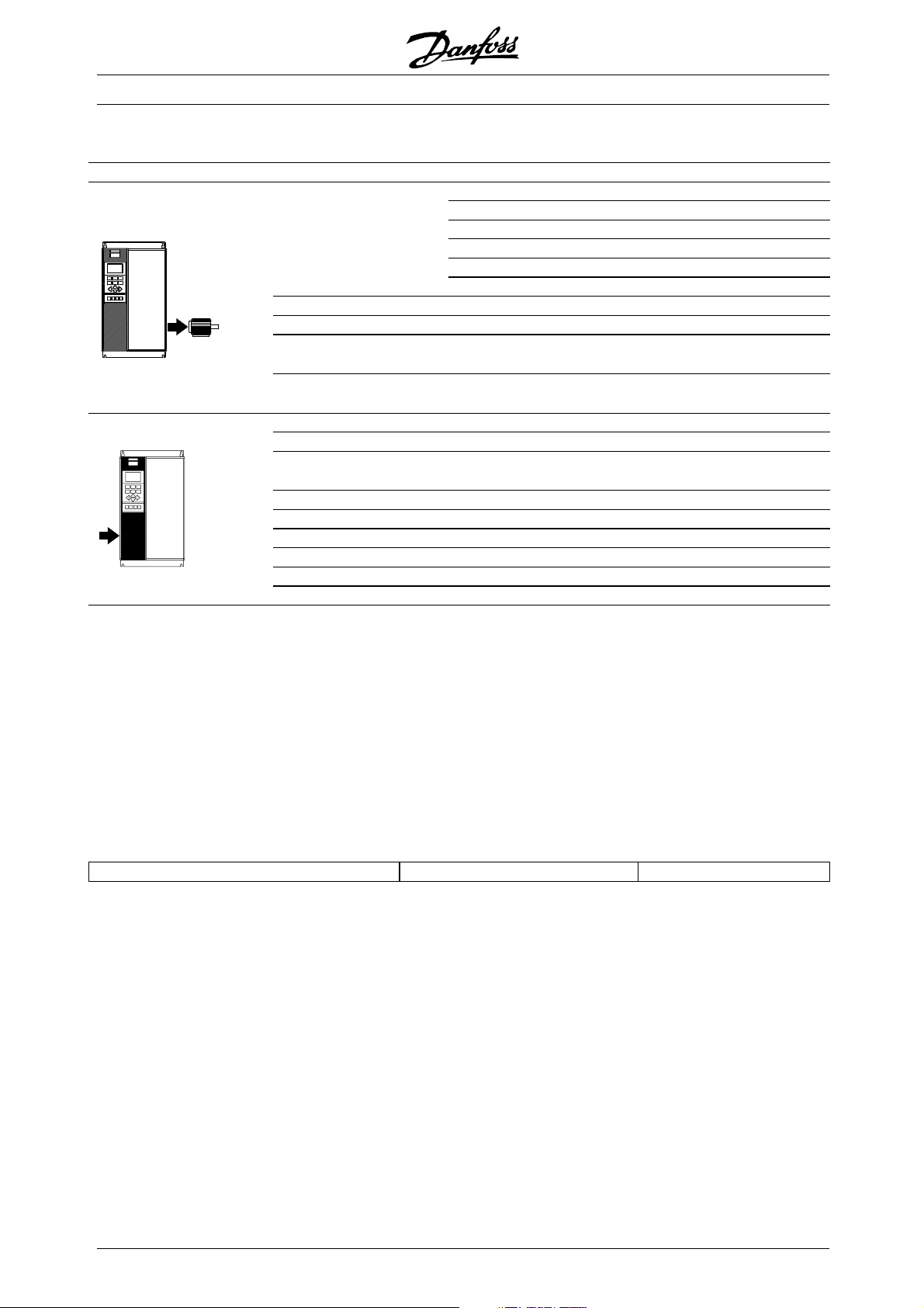
Unpacking and ordering a VLT frequency converter ................................................ 11
Type code ordering number string ......................................................................... 11
Ordering form ......................................................................................................... 13
................................................................................. 4
Installation ......................................................................................................... 14
General technical data ............................................................................................ 14
Technical data, mains supply 3 x 380-460V ............................................................ 18
Fuses ..................................................................................................................... 20
Mechanical dimensions .......................................................................................... 21
Mechanical installation ............................................................................................ 23
General information about electrical installation ...................................................... 25
High voltage warning .............................................................................................. 25
Earthing .................................................................................................................. 25
Cables .................................................................................................................... 25
Screened/armoured cables .................................................................................... 25
Extra protection with regard to indirect contact ....................................................... 25
RFI switch .............................................................................................................. 26
High voltage test .................................................................................................... 28
Heat emission from VLT 7000 Booster ................................................................... 28
Ventilation of integrated VLT 7000 Booster ............................................................. 28
EMC-correct electrical installation ........................................................................... 29
Use of EMC-correct cables .................................................................................... 31
Electrical installation - earthing of control cables ..................................................... 32
Electrical installation, enclosures ............................................................................. 33
Tightening-up torque and screw sizes .................................................................... 35
Mains connection ................................................................................................... 35
Motor connection ................................................................................................... 35
Direction of motor rotation ...................................................................................... 36
Motor cables .......................................................................................................... 36
Motor thermal protection ........................................................................................ 37
Earth connection .................................................................................................... 37
DC bus connection ................................................................................................ 37
High-voltage relay ................................................................................................... 37
Control card ........................................................................................................... 37
Electrical installation, control cables ........................................................................ 38
Switches 1-4 .......................................................................................................... 39
Bus connection ...................................................................................................... 39
Programming .................................................................................................... 40
Control unit LCP ..................................................................................................... 40
Control keys for parameter setup ........................................................................... 40
Indicator lamps ....................................................................................................... 41
Local control .......................................................................................................... 41
MG.70.A1.02 - VLT is a registered Danfoss trademark
1
Page 2

VLT® 7000 Booster
Display mode ......................................................................................................... 42
Navigation between display modes ........................................................................ 44
Changing data ........................................................................................................ 45
Manual initialisation ................................................................................................. 45
Quick Menu ............................................................................................................ 46
Operation and Display 001-017 .............................................................................. 48
The Setup configuration ......................................................................................... 48
Setup of user-defined readout ................................................................................ 49
Load and Motor 100-117 ....................................................................................... 55
Configuration .......................................................................................................... 55
Motor power factor (Cos ø) .................................................................................... 60
Inputs and outputs 300-328 ................................................................................... 68
Analogue inputs ..................................................................................................... 69
Analogue/digital outputs ......................................................................................... 72
Relay outputs ........................................................................................................ 75
Application functions 400-427 ................................................................................ 77
PID for process control ........................................................................................... 81
PID overview .......................................................................................................... 83
Feedback handling ................................................................................................. 83
Service functions 600-631 ...................................................................................... 88
Cascade Controller Settings ..................................................................... 93
Operation modes ................................................................................................... 93
Mode no ................................................................................................................ 93
Control type ........................................................................................................... 94
Fixed lead pump control (mode 1-8) ....................................................................... 94
Alternating lead pump control (Mode 9-14) ............................................................. 94
AUX pump ............................................................................................................. 94
Staging and destaging order .................................................................................. 94
FILO: First in, last out ............................................................................................. 95
LRHIMRHO: Least-running-hours-in, most running-hours out ................................ 95
Default value for digital input on terminal 18 (DI18) .................................................. 95
No. of pumps, excl. AUX pump ............................................................................. 95
Wiring diagram mode 1-8 ....................................................................................... 96
Wiring diagram modes 9-14 .................................................................................. 97
Parameter settings ......................................................................................... 98
Quick menu 17 Par. 700 Cascade Mode ................................................................ 98
Quick menu 18 Par. 701 Pump combination .......................................................... 98
Quick menu 19 Par. 702 Staging bandwidth % ..................................................... 99
Quick menu 20 Par. 703 SBW Destage delay ....................................................... 99
Quick menu 21 Par. 704 SBW Stage delay ......................................................... 100
Quick menu 22 Par. 705 Override bandwidth ...................................................... 100
Quick menu 23 Par. 706 Override Bandwidth timer ............................................. 101
Quick menu 24 Par. 707 Destage by timer .......................................................... 101
Staging and destaging of fixed speed pumps ............................... 102
Quick menu 25 Par. 708 Staging frequency ........................................................ 102
Quick menu 26 Par. 709 Destaging frequency ..................................................... 102
Staging and destaging og fixed speed pumps .............................. 103
Quick menu 27 Par. 710 Delay before running on mains ..................................... 103
2
MG.70.A1.02 - VLT is a registered Danfoss trademark
Page 3

VLT® 7000 Booster
Auxiliary pump/sleep mode .................................................................... 104
Quick menu 28 Par. 711 Sleep/AUX timer ........................................................... 104
Quick menu 29 Par. 712 Sleep/AUX frequency .................................................... 104
Quick Menu 30 Par. 713 Wake up/disable aux - frequency ................................. 104
Quick Menu 31 Par. 714 Boost setpoint .............................................................. 105
Virtual control curve ................................................................................... 106
Example ............................................................................................................... 106
Quick Menu 32 Par. 418 setpoint 1 ...................................................................... 106
Quick Menu 33 Par. 419 setpoint 2 ...................................................................... 106
Start and stop functionality ..................................................................... 107
Quick Menu 34 Par. 719 Pump enable ................................................................. 107
Quick Menu 35 Par. 720 Pump running hours ...................................................... 108
Feedback transmitter wiring ................................................................................. 108
All about VLT 7000 Booster ..................................................................... 110
Status messages .................................................................................................. 110
List of warnings and alarms .................................................................................. 112
Aggressive environments ...................................................................................... 117
Calculation of resulting reference .......................................................................... 117
Earth leakage current ........................................................................................... 118
Extreme running conditions .................................................................................. 118
Peak voltage on motor ......................................................................................... 120
Switching on the input .......................................................................................... 120
Acoustic noise ...................................................................................................... 121
Derating for ambient temperature ......................................................................... 121
Derating for air pressure ....................................................................................... 122
Derating for running at low speed ......................................................................... 122
Derating for long motor cables or cables with larger cross-section ....................... 122
Derating for high switching frequency ................................................................... 122
Vibration and shock .............................................................................................. 123
Air humidity ......................................................................................................... 123
Efficiency ............................................................................................................. 124
Mains supply interference/harmonics .................................................................... 125
Power factor ........................................................................................................ 125
EMC test results (Emission, Immunity) .................................................................. 127
EMC Immunity ..................................................................................................... 128
Definitions ........................................................................................................... 130
Factory settings .................................................................................................... 132
MG.70.A1.02 - VLT is a registered Danfoss trademark
3
Page 4

VLT® 7000 Booster
VLT 7000 Booster
Operating instructions
Software version: 30.00/0.00/1.x
These operating instructions can be used for all VLT 7000
Booster frequency converters with software version 30.00/
0.00/1.0x.
The software version number can be seen from parameter
624.
176FA229.10
4
MG.70.A1.02 - VLT is a registered Danfoss trademark
Page 5

The voltage of the frequency converter
is dangerous whenever the equipment
is connected to mains. Incorrect
installation of the motor or the frequency converter
may cause damage to the equipment, serious
personal injury or death.
Consequently, the instructions in this manual,
as well as national and local rules and safety
regulations, must be complied with.
■Safety regulations
1. The frequency converter must be disconnected
from mains if repair work is to be carried out. Check
that the mains supply has been disconnected
and that the necessary time has passed before
removing motor and mains plugs.
2. The [OFF/STOP] key on the control panel of
the frequency converter does n
the equipment from mains and is thus n
be used as a safety switch.
3. Correct protective earthing of the equipment
must be established, the user must be protected
against supply voltage, and the motor must be
protected against overload in accordance with
applicable national and local regulations.
4. The earth leakage currents are higher than 3.5 mA.
5. Protection against motor overload is included in
the factory setting. Parameter 117, Motor thermal
protection default value is ETR trip 1.
N
ote: The function is initialised at 1.0 x rated
motor current and rated motor frequency (see
parameter 117, Motor thermal protection).
ot disconnect
ot to
VLT® 7000 Booster
6. Do n
7. Please note that the frequency converter has
■Warning against unintended start
1. The motor can be brought to a stop by
2. While parameters are being changed, the
3. A motor that has been stopped may start if faults
■Useonisolatedmains
See section RFI Switch regarding use on isolated mains.
ot remove the plugs for the motor and mains
supply while the frequency converter is connected
to mains. Check that the mains supply has been
disconnected and that the necessary time has
passed before removing motor and mains plugs.
more voltage inputs than L1, L2 and L3, when
theDC-busterminalsareused.
Check that a
disconnected and that the necessary time has
passed before repair work is commenced.
means of digital commands, bus commands,
references or a local stop, while the frequency
converter is connected to mains.
If personal safety considerations make it necessary
to ensure that no unintended start occurs, t
stop functions are not sufficient.
motor may start. Consequently, t
[OFF/STOP] must always be activated, following
which data can be modified.
occur in the electronics of the frequency converter,
or if a temporary overload or a fault in the supply
mains or the motor connection ceases.
ll voltage inputs have been
he stop key
Booster
Introduction to
hese
MG.70.A1.02 - VLT is a registered Danfoss trademark
5
Page 6

VLT® 7000 Booster
Warning:
Touching the electrical parts may be fatal - even after the equipment
has been disconnected from mains.
Using VLT 7002-7005, 380-460 V: wait at least 4 minutes
Using VLT 7006-7072, 380-460 V: wait at least 15 minutes
176FA230.10
6
MG.70.A1.02 - VLT is a registered Danfoss trademark
Page 7
VLT® 7000 Booster
■Introduction to Operating Instructions
These Operating Instructions are a tool intended for persons who are to install, operate and program the
VLT 7000 Booster.
These Operating Instructions are divided into four sections with information about VLT 7000 Booster.
Introduction to Booster: This section tells you the advantages you can obtain by using a VLT
7000 Booster - such as AEO, Automatic Energy Optimization, RFI
filters and other HVAC-relevant functions. This section also contains
examples of application as well as information about Danfoss.
Installation: This section tells you how to carry out mechanically correct installation
of the VLT 7000 Booster. In addition, this section includes a description
of how to ensure that the installation of your VLT 7000 Booster
is EMC-correct. Furthermore, a list is given of mains and motor
connections, together with a description of the control card terminals.
Programming: This section describes the control unit and the software parameters for
the VLT 7000 Booster. Also included is a guide to the Quick Setup
menu, which allows you to get started on your application very quickly.
Booster
Introduction to
All about VLT 7000 Booster This section gives information about status, warning and error
messages from the VLT 7000 Booster. Additionally, information is given
on technical data, service, factory settings and special conditions.
Indicates a general warning
NB!:
Indicates something to be noted by the reader
Indicates a high-voltage warning
MG.70.A1.02 - VLT is a registered Danfoss trademark
7
Page 8
■Control principle
A frequency converter rectifies AC voltage from
mains into DC voltage, after which this DC
voltage is converted into a AC current with a
variable amplitude and frequency.
VLT® 7000 Booster
The motor is thus supplied with variable voltage and
frequency, which enables infinitely variable speed
control of three-phased, standard AC motors.
1. Mains voltage
3 x 380 - 460 V AC, 50 / 60 Hz.
. Rectifier
2
A three-phase rectifier bridge that rectifies AC
current into DC current.
3
. Intermediate circuit
DC voltage = 1.35 x mains voltage [V].
4
. Intermediate circuit coils
Even out the intermediate circuit voltage and reduce
the harmonic current feedback to the mains supply.
5
. Intermediate circuit capacitors
Even out the intermediate circuit voltage.
6
. Inverter
Converts DC voltage into variable AC voltage
with a variable frequency.
7
. Motor voltage
Variable AC voltage, 0-100% of mains supply voltage.
8
. Control card
This is where to find the computer that controls
the inverter which generates the pulse pattern by
which the DC voltage is converted into variable
AC voltage with a variable frequency.
8
MG.70.A1.02 - VLT is a registered Danfoss trademark
Page 9
■AEO - Automatic Energy Optimization
Normally, the U/f characteristics have to be set on the
basis of the expected load at different frequencies.
However, knowing the load at a given frequency in an
installation is often a problem. This problem can be
solved by using a VLT 7000 Booster with its integral
Automatic Energy Optimization (AEO), which ensures
optimum energy utilization. All VLT 7000 Booster
units feature this function as a factory setting, i.e. it
is not necessary to adjust the frequency converter
U/f ratio in order to obtain maximum energy savings.
In other frequency converters, the given load and
voltage/frequency ratio (U/f) must be assessed to carry
out correct setting of the frequency converter.
Using Automatic Energy Optimization (AEO),
you no longer need to calculate or assess the
system characteristics of the installation, since
Danfoss VLT 7000 Booster units guarantee
optimum, load-dependent energy consumption
by the motor at all times.
VLT® 7000 Booster
Booster
Introduction to
The figure on the right illustrates the working
range of the AEO function, within which energy
optimization is enabled.
If the AEO function has been selected in parameter 101,
Torque characteristics, this function will be constantly
active. If there is a major deviation from the optimum U/f
ratio, the frequency converter will quickly adjust itself.
Advantages of the AEO function
• Automatic energy optimization
• Compensation if an oversize motor is used
• AEO matches operations to daily or
seasonal fluctuations
• Energy savings in a constant air volume system
• Compensation in the oversynchronous
working range
• Reduces acoustic motor noise
MG.70.A1.02 - VLT is a registered Danfoss trademark
9
Page 10
■PC software and serial communication
Danfoss offers various options for serial communication.
Using serial communication, it is possible to monitor,
program and control one or several frequency
converters from a centrally located computer.
All VLT 7000 Booster units have a RS 485 port
and the FC protocol as standard.
Using the RS 485 port enables communication, e.g.
with a PC. A Windows
TM
program, called MCT 10,is
available for this purpose. It can be used to monitor,
program and control one or several VLT 7000 Booster
units. For further information, contact Danfoss.
500-566 Serial communication
NB!:
Information on the use of RS-485 serial interface
is not included in this manual.
VLT® 7000 Booster
10
MG.70.A1.02 - VLT is a registered Danfoss trademark
Page 11

■Unpacking and ordering a VLT frequency converter
If you are in doubt as to which frequency converter
you have received and which options it contains,
use the following to find out.
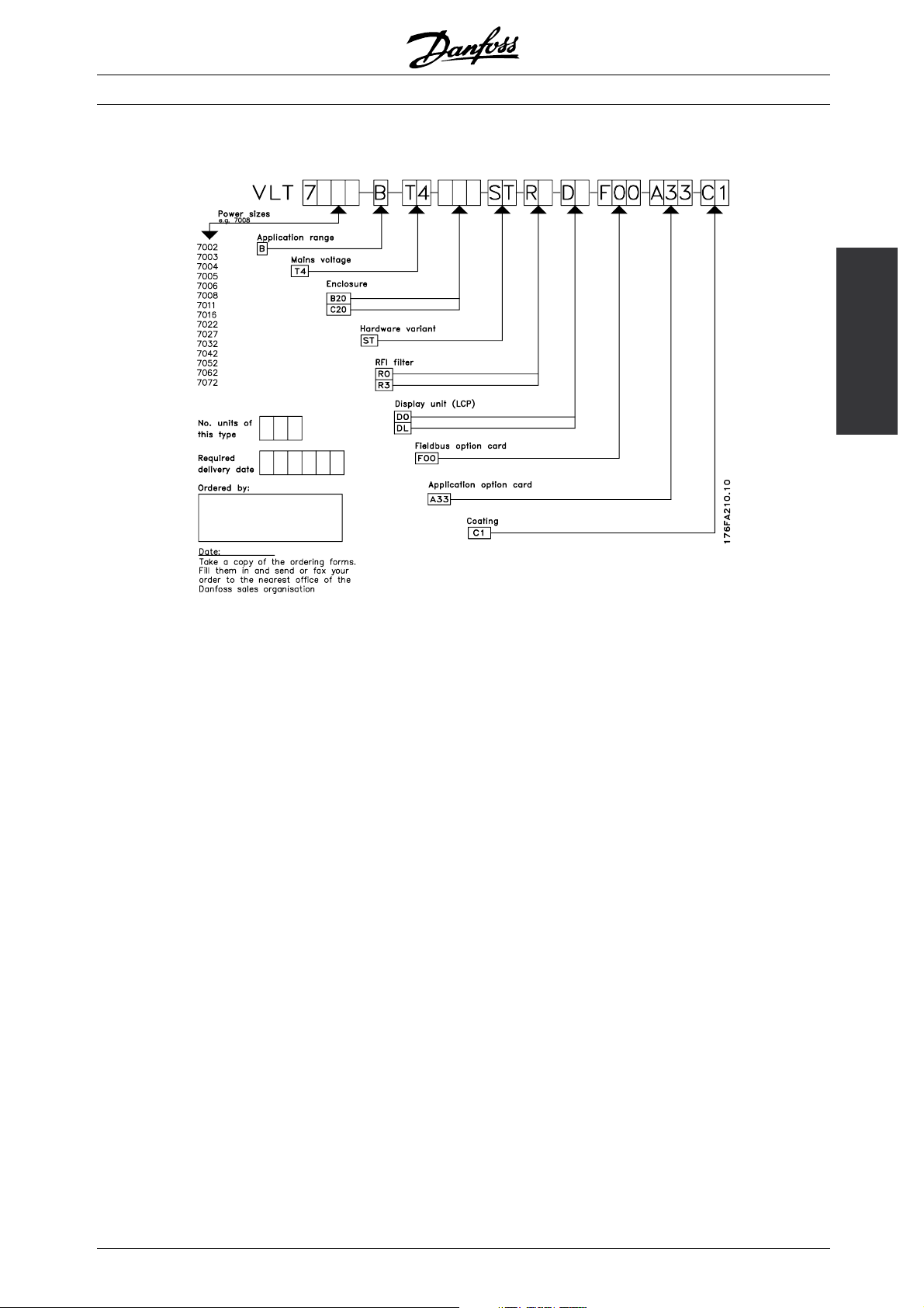
■Type code ordering number string
On the basis of your order, the frequency converter is
given an ordering number that can be seen from the
nameplate on the unit. The number may look as follows:
VLT-7008-B-T4-B20-R3-DL-F00-A33
This means that the frequency converter ordered is a
VLT 7008 for three-phase mains voltage of 380-460 V
(T4) in Bookstyle enclosure IP 20 (B20). The hardware
variant is with integral RFI filter, classes A & B (R3). The
frequency converter features a control unit (DL)without
an option card (F00). Character no. 8 ( B) indicates
the application range of the unit: B = Booster.
Hardware variant
The units in the programme are available in the
following hardware variants:
ST: Standard unit with or without control
unit. Most of the types are with
DC terminals, please see DC bus
connection for exceptions.
VLT® 7000 Booster
Booster
Introduction to
RFI filter
Bookstyle units always come with an integral RFI
filter that complies with EN 55011-B with 20 m
screened/armoured motor cable and EN 55011-A1
with 150 m screened/armoured motor cable. Units
for a mains voltage of 380-460 V and a motor
power of up to 7.5 kW (VLT 7011) are always
supplied with an integral class A1 & B filter. Units
forhighermotorpowercanbeorderedeitherwith
or without an RFI filter.
Control unit (keypad and display)
All types of units in the programme, can be ordere
either with or without the control unit.
Conformal Coating
All types of units in the programme are available
only with conformal coating of the PCB.
d
MG.70.A1.02 - VLT is a registered Danfoss trademark
11
Page 12
380-460 V
VLT® 7000 Booster
Typecode
Position in string
1.1 kW/1.5 HP 7002 XXX X
1.5 kW/2.0 HP 7003 XXX X
2.2 kW/3.0 HP 7004 XXX X
3.0 kW/4.0 HP 7005 XXX X
4.0 kW/5.0 HP 7006 XXX X
5.5 kW/7.5 HP 7008 XXX X
7.5 kW/10 HP 7011 XXX X
11 kW/15 HP 7016 X X XX
15 kW/20 HP 7022 X X XX
18.5 kW/25 HP 7027 X X XX
22 kW/30 HP 7032 X X XX
30 kW/40 HP 7042 X X XX
37 kW/50 HP 7052 X X XX
45 kW/60 HP 7062 X X XX
55 kW/75 HP 7072 X X XX
Voltage
T4: 380-460 VAC
Enclosure
B20: Bookstyle IP 20
C20: Compact IP 20
T4
9-10
B20
11-13
Hardware variant
ST: Standard
RFI filter
R0: Without filter
R3: Class A1 and B filter
C20
11-13
ST
14-15
R0
16-17
R3
16-17
Optional selections, 200-600 V
Display Position: 18-19
D0 Without LCP
DL With LCP
12
MG.70.A1.02 - VLT is a registered Danfoss trademark
Page 13
■Ordering form
VLT® 7000 Booster
Booster
Introduction to
MG.70.A1.02 - VLT is a registered Danfoss trademark
13
Page 14

VLT® 7000 Booster
■General t echnical data
Mains supply (L1, L2, L3):
Supply voltage 380-460 V units ........................................................................ 3 x 380/400/415/440/460 V ±10%
Supply frequency ............................................................................................................................ 48-62 Hz ± 1%
Max. imbalance of supply voltage .................................................................................................................. ± 3%
VLT 6002-6011, 380-460 V .................................................................................... ±2.0% of rated supply voltage
VLT 6016-6072, 380-460 V .................................................................................... ±1.5% of rated supply voltage
True Power factor (λ) ...................................................................................................... 0.90 nominal at rated load
Displacement Power Factor (cos. ϕ) ............................................................................................ near unity (>0.98)
No. of switches on supply input L1, L2, L3 .......................................................................... approx. 1 time/2 min.
Max. short-circuit current ....................................................................................................................... 100.000 A
VLT output data (U, V, W):
Output voltage ................................................................................................................ 0-100% of supply voltage
Output frequency 7002-7062, 380-460V .............................................................................. 0-120 Hz, 0-1000 Hz
Output frequency 7072, 380-460V ......................................................................................... 0-120 Hz, 0-450 Hz
Rated motor voltage, 380-460 V units .............................................................................. 380/400/415/440/460V
Rated motor frequency ............................................................................................................................ 50/60 Hz
Switching on output ................................................................................................................................. Unlimited
Ramp times ....................................................................................................................................... 1 - 3600 sec.
Torque characteristics:
Starting torque ............................................................................................................................... 110% for 1 min.
Starting torque (parameter 110 High break-away torque) ....................................... Max. torque: 160% for 0.5 sec.
Acceleration torque ....................................................................................................................................... 100%
Overload torque ............................................................................................................................................ 110%
Control card, digital inputs:
Number of programmable digital inputs ................................................................................................................ 8
Terminal nos. ............................................................................................................ 16, 17, 18, 19, 27, 29, 32, 33
Voltage level ........................................................................................................... 0-24 V DC (PNP positive logics)
Voltage level, logical ’0’ ............................................................................................................................ < 5 V DC
Voltage level, logical ’1’ ........................................................................................................................... >10 V DC
Maximum voltage on input ........................................................................................................................ 28 V DC
Input resistance, R
........................................................................................................................................ 2 k
i
Scanning time per input ............................................................................................................................. 3 msec.
Basic galvanic isolation: All d igital inputs are galvanically isolated from the supply voltage . In addition,
the digital inp uts can be isolated from the other terminals on the control card by connecti
ng an
external 24 V DC supply and opening switch 4. See Switches 1-4.
Control card, analogue inputs
No. of programmable analogue voltage inputs/thermistor inputs .......................................................................... 2
Terminal nos. ................................................................................................................................................ 53, 54
Voltage level .......................................................................................................................... 0 - 10 V DC (scalable)
Input resistance, R
......................................................................................................................... approx.10k
i
No. of programmable analogue current inputs ..................................................................................................... 1
Terminal no ground. ............................................................................................................................................ 55
Current range ...................................................................................................................... 0/4 - 20 mA (scalable)
Input resistance, R
...................................................................................................................................... 200
i
Resolution .......................................................................................................................................... 10 bit + sign
Accuracy on input .......................................................................................................... Max. error 1% of full scale
Scanning time per input ............................................................................................................................. 3 msec.
14
MG.70.A1.02 - VLT is a registered Danfoss trademark
Page 15

VLT® 7000 Booster
Basic galvanic isolation: All analogue inputs are galvanically isolated from the supply v oltage and other high-voltage terminals.
Control card, pulse input:
No. of programmable pulse inputs ........................................................................................................................ 3
Terminal nos. .......................................................................................................................................... 17, 29, 33
Max. frequency on terminal 17 ...................................................................................................................... 5 kHz
Max. frequency on terminals 29, 33 ............................................................................ 20 kHz (PNP open collector)
Max. frequency on terminals 29, 33 ........................................................................................... 65 kHz (Push-pull)
Voltage level ........................................................................................................... 0-24 V DC (PNP positive logics)
Voltage level, logical ’0’ ............................................................................................................................ < 5 V DC
Voltage level, logical ’1’ ........................................................................................................................... >10 V DC
Maximum voltage on input ........................................................................................................................ 28 V DC
Input resistance, R
Scanning time per input ............................................................................................................................. 3 msec.
Resolution .......................................................................................................................................... 10 bit + sign
Accuracy (100-1 kHz), terminals 17, 29, 33 ............................................................... Max. error: 0.5% of full scale
Accuracy (1-5 kHz), terminal 17 ................................................................................. Max. error: 0.1% of fullscale
Accuracy (1-65 kHz), terminals 29, 33 ....................................................................... Max. error: 0.1% of full scale
Basic galvanic isolation: All pulse inputs are galvanically isolated from the supply voltage. In addition,
pulse inputs can be isolated from the other terminals on the control card by connecting an external
24 V DC supply and opening switch 4. See Switches 1-4.
........................................................................................................................................ 2 k
i
Installation
Control card, digital/pulse and analogue outputs:
No. of programmable digital and analogue outputs .............................................................................................. 2
Terminal nos. ................................................................................................................................................ 42, 45
Voltage level at digital/pulse output ...................................................................................................... 0 - 24 V DC
Minimum load to ground (terminal 39) at digital/pulse output ....................................................................... 600
Frequency ranges (digital output used as pulse output) ............................................................................ 0-32 kHz
Current range at analogue output ........................................................................................................ 0/4 - 20 mA
Maximum load to ground (terminal 39) at analogue output ........................................................................... 500
Accuracy of analogue output ..................................................................................... Max. error: 1.5% of full scale
Resolution on analogue output. ....................................................................................................................... 8 bit
Basic galvanic isolation: All digital and analogue outputs are galvanically isolated from the
supply voltage and other high-voltage terminals.
Control card, 24 V DC supply:
Terminal nos. ................................................................................................................................................ 12, 13
Max. load .................................................................................................................................................. 200 mA
Terminal nos. ground .................................................................................................................................... 20, 39
Basic galvanic isolation: The 24 V DC supply is galvanically isolated from the supply voltage,
but has the same potential as the analogue outputs.
Control card, RS 485 serial communication:
Terminal nos. .............................................................................................................. 68 (TX+, RX+), 69 (TX-, RX-)
Basic galvanic isolation.
Relay outputs:
No. of programmable relay outputs ...................................................................................................................... 2
Terminal nos., control card ..................................................................................................................... 4-5 (make)
Max. terminal load (AC) on 4-5, control card ........................................................................... 50 V AC, 1 A, 60 VA
Max. terminal load (DC-1 (IEC 947)) on 4-5, control card ......................................................... 75 V DC, 1 A, 30 W
Terminal nos., power card and relay card ............................................................................ 1-3 (break), 1-2 (make)
MG.70.A1.02 - VLT is a registered Danfoss trademark
15
Page 16

VLT® 7000 Booster
Max. terminal load (AC) on 1-3, 1-2 power card ................................................................... 240 V AC, 2 A, 60 VA
Max. terminal load DC-1 (IEC 947) on 1-3, 1-2, power card and relay card ....................................... 50 V DC, 2 A
Min. terminal load on 1-3, 1-2, power card ...................................................... 24 V DC, 10 mA, 24 V AC, 100 mA
Cable lengths and cross-sections:
Max. motor cable length, screened cable ..................................................................................................... 150 m
Max. motor cable length, unscreened cable ................................................................................................. 300 m
Max. motor cable length, screened cable VLT 7011 380-460 V .................................................................... 100 m
Max. DC-bus cable length, screened cable ........................................... 25 m from frequency converter to DC bar.
Max. cable cross-section to motor, see next section
Max. cross-section for control cables ....................................................................................... 1.5 mm
Max. cross-section for serial communication ............................................................................ 1.5 mm
Control characteristics:
Frequency range .................................................................................................................................. 0 - 1000 Hz
Resolution on output frequency ............................................................................................................. ±0.003 Hz
System response time ............................................................................................................................... 3 msec.
Speed, control range (open loop) ..................................................................................... 1:100 of synchro. speed
Speed, accuracy (open loop) ............................................................................ < 1500 rpm: max. error ± 7.5 rpm
>1500 rpm: max. error of 0.5% of actual speed
Process, accuracy (closed loop) ....................................................................... < 1500 rpm: max. error ± 1.5 rpm
>1500 rpm: max. error of 0.1% of actual speed
All control characteristics are based on a 4-pole asynchronous motor
2
/16 AWG
2
/16 AWG
Accuracy of display readout (parameters 009-012, Display readout):
Motor current [5] 0-140% load ............................................................... Max. error: ±2.0% of rated output current
Power kW [6], Power HP [7], 0-90% load .................................................. Max. error: ±5% of rated output power
Externals:
Enclosure ....................................................................................................................................................... IP 20
Vibration test .................................. 0.7 g RMS 18-1000 Hz random. 3 directions for 2 hours (IEC 68-2-34/35/36)
Max. relative humidity ............................................................ 93 % + 2 %, -3 % (IEC 68-2-3) for storage/transport
Max. relative humidity ............................................... 95 % non condensing (IEC 721-3-3; class 3K3) for operation
Aggressive environment (IEC 721-3-3) ........................................................................................ Coated class 3C3
Ambient temperature, 7002-7011 380-460 V, Bookstyle, IP 20 ............. Max. 45°C (24-hour average max. 40°C)
Ambient temperature, 7016-7072 380-460 V, IP 20 ............................... Max. 40°C (24-hour average max. 35°C)
Min. ambient temperature in full operation ........................................................................................................ 0°C
Min. ambient temperature at reduced performance ..................................................................................... -10°C
Temperature during storage/transport ............................................................................................. -25 - +65/70°C
Max. altitude above sea level ...................................................................................................................... 1000 m
EMC standards applied, Emission ......................................... EN 61000-6-3/4, EN 61800-3, EN 55011, EN 55014
EMC standards applied, Immunity ................................................................................................ EN 50082-2, EN
61000-4-2, IEC 1000-4-3, EN 61000-4-4, EN 61000-4-5, ENV 50204, EN 61000-4-6, VDE 0160/1990.12
Relay outputs on the Cascade Card:
Relay 71-78: ......................................................................................................... Terminal 8 A-D and 71-78 make
Max. cross section: .................................................................................................................................. 1,5 mm
Torque: ............................................................................................................................................. 0,22-0,25 Nm
2
VLT 7000 Boosterprotection
• Electronic motor thermal protection against overload.
• Temperature monitoring of heat-sink ensures that the frequency converter cuts out if the temperature reaches
90°C. An overtemperature can only be reset when the temperature of the heat-sink has fallen below 60°C.
• The frequency converter is protected against short-circuiting on motor termi
16
MG.70.A1.02 - VLT is a registered Danfoss trademark
nals U, V, W.
Page 17

VLT® 7000 Booster
• The frequency converter is protected against earth fault on motor terminals U, V, W.
• Monitoring of the intermediate circuit voltage ensures that the frequency converter cuts out if
the intermediate circuit voltage gets too high or too low.
• If a motor phase is missing, the frequency converter cuts out.
• If there is a mains fault, the frequency converter is able to carry out a controlled decelleration.
• If a mains phase is missing, the frequency converter will cut out or autoderate when a load is placed on the motor
.
Installation
MG.70.A1.02 - VLT is a registered Danfoss trademark
17
Page 18
VLT® 7000 Booster
■Technical data, mains supply 3 x 380-460V
According to international requirements VLT type 7002 7003 7004 7005 7006 7008 7011
I
[A] (380-440
Output current
VLT,N
I
VLT, MAX
(60 s) [A]
(380-440 V)
I
[A] (441-460
VLT, N
I
(60 s) [A]
VLT, MAX
(441-460 V)
Output power S
Ty p ic a l s ha f t
output
Ty p ic a l s ha f t
output
Max. cable
[kVA] (400 V) 2.2 2.9 4.0 5.2 7.2 9.3 11.5
VLT,N
S
[kVA] (460 V) 2.4 2.7 3.8 5.0 6.5 8.8 11.2
VLT,N
P
VLT,N
P
VLT,N
2
[mm
]/[AWG]
cross-section to
motor
Max. input
current
(RMS) I
Max. cable
I
[A] (380 V) 2.8 3.8 5.3 7.0 9.1 12.2 15.0
L,N
[A] (460 V) 2.5 3.4 4.8 6.0 8.3 10.6 14.0
L,N
2
[mm
]/[AWG]
cross-section
power
Max. pre-fuses [-]/UL1)[A] 16/6 16/10 16/10 16/15 25/20 25/25 35/30
Mains contactor [Danfoss type] CI 6 CI 6 CI 6 CI 6 CI 6 CI 6 CI 6
Efficiency
3)
Weight IP 20 [kg] 8 8 8.5 8.5 10.5 10.5 10.5
Power loss at
max. load. [W]
Enclosure VLT type IP 20
3.0 4.1 5.6 7.2 10.0 13.0 16.0
V)
3.3 4.5 6.2 7.9 11.0 14.3 17.6
3.0 3.4 4.8 6.3 8.2 11.0 14.0
V)
3.3 3.7 5.3 6.9 9.0 12.1 15.4
[kW] 1.1 1.5 2.2 3.0 4.0 5.5 7.5
[HP] 1.5 2 3 - 5 7.5 10
2) 4)
4/10 4/10 4/10 4/10 4/10 4/10 4/10
2) 4)
4/10 4/10 4/10 4/10 4/10 4/10 4/10
0.96 0.96 0.96 0.96 0.96 0.96 0.96
Total 67 92 110 139 198 250 295
1. Fortypeoffuse,seesectionFuses.
2. American Wire Gauge.
3. Measured using 30 m screened motor cables at rated load and rated frequency.
4. Max. cable cross section is the maximum possible cable cross section that can be fitted on the terminals.
Always comply with national and local regulations on min. cable cross-sectio
n.
18
MG.70.A1.02 - VLT is a registered Danfoss trademark
Page 19
VLT® 7000 Booster
■Technical data, mains supply 3x380-460V
According to international requirements VLT type 7016 7022 7027 7032 7042
Output current I
Output power S
Ty pi ca l s ha ft o ut p ut P
Ty pi ca l s ha ft o ut p ut P
Max. cable cross-section to
motor and DC-bus, IP 20
Min. cable cross-section to
motor and DC-bus
Max. input current I
(RMS) I
Max. cable cross-section
power, IP 20
Max. pre-fuses [-]/UL1)[A] 63/40 63/40 63/50 63/60 80/80
Mains contactor [Danfoss type] CI 9 CI 16 CI 16 CI 32 CI 32
Efficiency at rated frequency 0.96 0.96 0.96 0.96 0.96
Weight IP 20 [kg] 21 21 22 27 28
Power loss at max. load. [W] 419 559 655 768 1065
Enclosure IP 20
1. Fortypeoffuse,seesectionFuses.
2. American Wire Gauge.
3. Measured using 30 m screened motor cables at rated load and rated frequency.
4. Min. cable cross-section is the smallest cable cross-section allowed to be fitted on the terminals. Max. cable cross section is the
maximum possible cable cross section that can be fitted on the terminals.
Always comply with national and local regulations on min. cable cross-sectio
[A] (380-440 V) 24.0 32.0 37.5 44.0 61.0
VLT,N
I
(60 s) [A]
VLT, MAX
(380-440 V)
I
[A] (441-460 V) 21.0 27.0 34.0 40.0 52.0
VLT,N
I
(60 s) [A]
VLT, MAX
(441-460 V)
[kVA] (400 V) 17.3 23.0 27.0 31.6 43.8
VLT,N
S
[kVA] (460 V) 16.7 21.5 27.1 31.9 41.4
VLT,N
VLT,N
VLT,N
2
[mm
]/[AWG]
2
[mm
]/[AWG]
[A] (380 V) 24.0 32.0 37.5 44.0 60.0
L,N
[A] (460 V) 21.0 27.6 34.0 41.0 53.0
L,N
2
[mm
]/[AWG]
26.4 35.2 41.3 48.4 67.1
23.1 29.7 37.4 44.0 57.2
[kW] 11 15 18.5 22 30
[HP] 15 20 25 30 40
2) 4)
16/6 16/6 16/6 35/2 35/2
2) 4)
10/8 10/8 10/8 10/8 10/8
2) 4)
16/6 16/6 16/6 35/2 35/2
n.
Installation
MG.70.A1.02 - VLT is a registered Danfoss trademark
19
Page 20
VLT® 7000 Booster
■Technical data, mains supply 3x380-460V
According to international requirements VLT type 7052 7062 7072
Output current I
I
VLT, MAX
I
VLT, MAX
Output power S
Ty p ic a l s h af t o u tp u t P
Ty p ic a l s h af t o u tp u t P
Max. cable cross-section to
motor and DC-bus, IP 20
Min. cable cross-section to
motor and DC-bus
Max. input current I
(RMS) I
Max. cable cross-section
power, IP 20
Max. pre-fuses [-]/UL1)[A] 100/100 125/125 150/150
Mains contactor [Danfoss type] CI 37 CI 61 CI 85
Efficiency at rated frequency 0.96 0.96 0.96
Weight IP 20 [kg] 41 42 43
Power loss at max. load. [W] 1275 1571 1851
Enclosure IP 20
1. For type of fuse, see section Fuses.
2. American Wire Gauge.
3. Measured using 30 m screened motor cables at rated load and rated frequency.
4. Min. cable cross-section is the smallest cable cross-section allowed to be fitted on the terminals. Max. cable cross
section is the maximum possible cable cross section that can be fitted on the terminals.
Always comply with national and local regulations on min. cable cross-section.
5. Aluminium cables with cross-section above 35 mm
2
must be connected by use of an Al-Cu connector.
[A] (380-440 V) 73.0 90.0 106
VLT,N
(60 s) [A] (380-440 V) 80.3 99.0 117
I
[A] (441-460 V) 65.0 77.0 106
VLT,N
(60 s) [A] (441-460 V) 71.5 84.7 117
[kVA] (400 V) 52.5 64.7 73.4
VLT,N
S
[kVA] (460 V) 51.8 61.3 84.5
VLT,N
[kW] 37 45 55
VLT,N
[HP] 50 60 75
VLT,N
2
[mm
[mm
[mm
2) 4) 5)
]/[AWG]
2
]/[AWG]
[A] (380 V) 72.0 89.0 104
L,N
[A] (460 V) 64.0 77.0 104
L,N
2
]/[AWG]
35/2 50/0 50/0
2) 4)
10/8 16/6 16/6
2) 4) 5)
35/2 50/0 50/0
■Fuses
Non UL compliance
If UL/cUL is not to be complied with, we recommend the above mentioned fuses or:
VLT 7002-7072 380-460 V type gG
Not following the recommendation may result
in unnecessary damage of the drive in case of
malfunction. Fuses must be designed for protection in
a circuit capable of supplying a maximum of 100000
A
(symmetrical), 500 V/600 V maximum.
rms
20
MG.70.A1.02 - VLT is a registered Danfoss trademark
Page 21

VLT® 7000 Booster
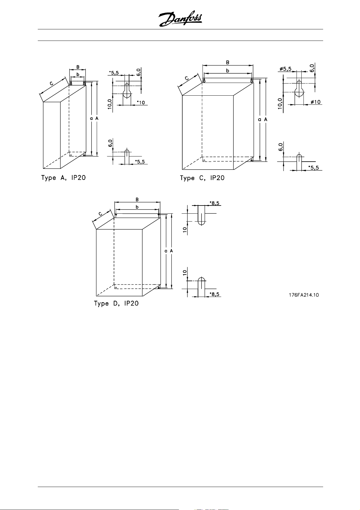
■Mechanical dimensions
All the below listed measurements are in mm.
VLT type A B C a b aa/bb Type
Bookstyle IP 20 380 - 460 V
7002 - 7005 395 90 260 384 70 100 A
7006 - 7011 395 130 260 384 70 100 A
IP 20 380 - 460 V
7002 - 7005 395 220 160 384 200 100 C
7006 - 7011 395 220 200 384 200 100 C
7016 - 7027 560 242 260 540 200 200 D
7032 - 7042 700 242 260 680 200 200 D
7052 - 7072 800 308 296 780 270 200 D
Installation
MG.70.A1.02 - VLT is a registered Danfoss trademark
21
Page 22
■Mechanical dimensions
VLT® 7000 Booster
22
MG.70.A1.02 - VLT is a registered Danfoss trademark
Page 23
■Mechanical installation
VLT® 7000 Booster
Please pay attention to the requirements
that apply to integration and field mounting
kit, see the below list. The information given
in the list must be observed to avoid serious damage
or injury, especially when installing large units.
The frequency converter must be installed vertically.
The frequency converter is cooled by means of air
circulation. For the unit to be able to release its cooling
air, the minimum distance over and below the unit
must be as shown in the illustration below.
To protect the unit from overheating, it must be
ensured that the ambient temperature does not rise
above the max. temperature stated for the frequency
converter and that the 24-hour average temperature is
not exceeded . The max. temperature and 24-hour
average can be seen from the General Technical Data.
If the ambient temperature is in the range of 45°C -55°
C, derating of the frequency converter will become
relevant, see Derating for ambient temperature.
The service life of the frequency converter will
be reduced if derating for ambient temperature
is not taken into account.
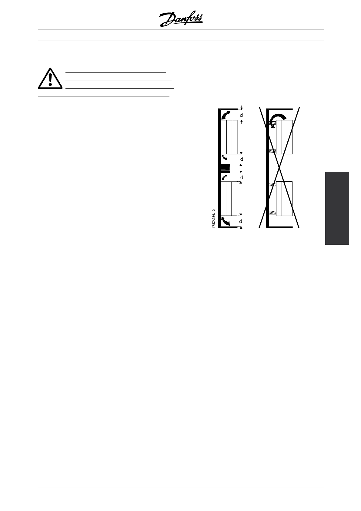
■Installation of VLT 7002-7072
All frequency converters must be installed in a
way that ensures proper cooling.
Cooling
Installation
All Bookstyle and Compact units require a minimum
space above and below the enclosure.
MG.70.A1.02 - VLT is a registered Danfoss trademark
23
Page 24
VLT® 7000 Booster
Side by side/flange by flange
All frequency converters can be mounted side
by side/flange by flange.
d[mm] Comments
Bookstyle
VLT 7002-7011, 380-460 V 100 Installation on a plane, vertical surface (no spacers)
Compact (all enclosure types)
VLT 7002-7011, 380-460 V 100 Installation on a plane, vertical surface (no spacers)
VLT 7016-7072, 380-460 V 200 Installation on a plane, vertical surface (no spacers)
24
MG.70.A1.02 - VLT is a registered Danfoss trademark
Page 25
VLT® 7000 Booster
■General information about electrical installation
■High voltage warning
The voltage of the frequency converter
is dangerous whenever the equipment is
connected to mains. Incorrect installation
of the motor or the frequency converter may cause
damage to the equipment, serious personal injury
or death. Consequently, the instructions in this
Design Guide, as well as national and local safety
regulations, must be complied with. Touching
the electrical parts may be fatal - even after
disconnection from mains: Using VLT 7002-7005,
380-460 V wait at least 4 minutes
Using VLT 7006-7072, 380-460 V wait at
least 15 minutes
NB!:
It is the user’s or certified electrician’s
responsibility to ensure correct earthing and
protection in accordance with applicable
national and local norms and standards.
■Earthing
The following basic issues need to be considered
when installing a frequency converter, so as to obtain
electromagnetic compatibility (EMC).
to the rear plate. It is necessary to remove insulating
paint or similar from the fastening points.
■Cables
Control cables and the filtered mains cable should
be installed separate from the motor cables so as to
avoid interference overcoupling. Normally, a distance
of 20 cm will be sufficient, but it is recommended
to keep the greatest possible distance wherever
possible, especially where cables are installed in
parallel over a substantial distance.
With respect to sensitive signal cables, such as
telephone cables and data cables, the greatest possible
distance is recommended with a minimum of 1 m per 5
m of power cable (mains and motor cable). It must be
pointed out that the necessary distance depends on
the sensitivity of the installation and the signal cables,
and that therefore no precise values can be stated.
If cable jaws are used, sensitive signal cables are not
to be placed in the same cable jaws as the motor
cable or brake cable. If signal cables are to cross
power cables, this should be done at an angle of
90 degrees. Remember that all interference-filled
in- or outgoing cables to/from a cabinet should
be screened/armoured or filtered.
See also EMC-correct electrical installation.
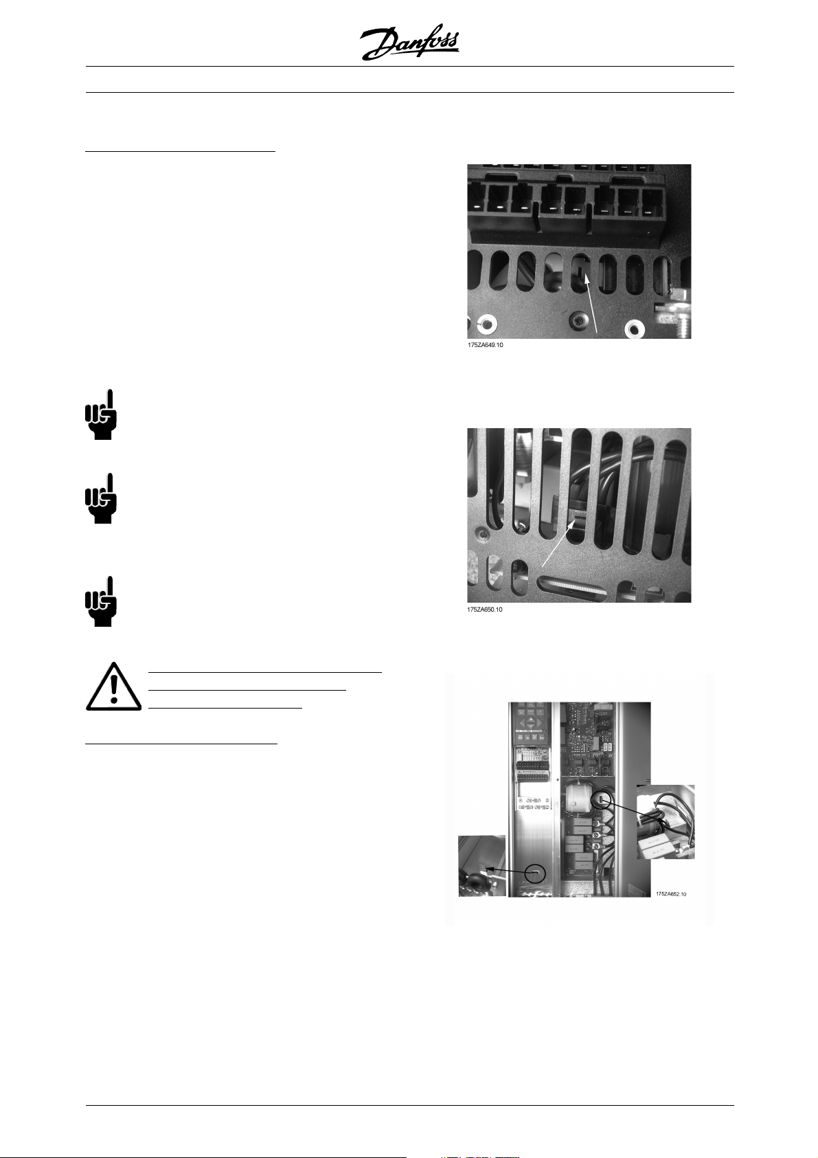
Installation
• Safety earthing: Please note that the frequency
converter has a high leakage current and must
be earthed appropriately for safety reasons.
Apply local safety regulations.
• High-frequency earthing: Keep the earth wire
connections as short as possible.
Connect the different earth systems at the lowest
possible conductor impedance. The lowest possible
conductor impedance is obtained by keeping the
conductor as short as possible and by using the
greatest possible surface area. A flat conductor, for
example, has a lower HF impedance than a round
conductor for the same conductor cross-section
C
. If more than one device is installed in cabinets,
VESS
the cabinet rear plate, which must be made of
metal, should be used as a common earth reference
plate. The metal cabinets of the different devices
are mounted on the cabinet rear plate using the
lowest possible HF impedance. This avoids having
different HF voltages for the individual devices and
avoids the risk of radio interference currents running
in connection cables that may be used between
the devices. The radio interference will have been
reduced. In order to obtain a low HF impedance, use
the fastening bolts of the devices as HF connection
■Screened/armoured cables
The screen must be a low HF-impedance screen.
This is ensured by using a braided screen of
copper, aluminium or iron. Screen armour int
ended
for mechanical protection, for example, is not
suitable for an EMC-correct installation. See
also Use of EMC-correct cables.
■Extra protection with regard to indirect
contact
ELCB relays, multiple protective earthing or earthing can
be used as extra protection, provided that local safety
regulations are complied with. In
the case of an earth
fault, a DC content may develop in the faulty current.
Never use ELCB relays, type A, since such relays
are not suitable for DC fault curr
ents.
If ELCB relays are used, this must be:
• Suitable for protecting equipment with a direct
current content (DC) in the fault
y current
(3-phase bridge rectifier)
• Suitable for power-up with short charging
current to earth
• Suitable for a high leakage current
MG.70.A1.02 - VLT is a registered Danfoss trademark
25
Page 26
■RFI switch
ains supply isolated from earth:
M
When the frequency converter is supplied from an
isolated mains source (IT mains), the RFI switch
must be closed (OFF). In the OFF position, the
internal RFI capacitors (filter capacitors) between
the chassis and the intermediate circuit are cut out
so as to avoid damaging the intermediate circuit
and to reduce the earth leakage currents (see IEC
1800-3). The position of the RFI switch can be
seen from in VLT 7000 enclosures.
Please also refer to the application note VLT
on IT mains, MN.90.CX.02.
NB!:
When the RFI switch is set to OFF parameter
407 Switching frequency max is only allowed
to be set to factory setting.
NB!:
TheRFIswitchisnottobeoperatedwith
mains supply connected to the unit. Check
that the mains supply has been disconnected
before operating the RFI switch.
VLT® 7000 Booster
Bookstyle IP 20
VLT 7002 - 7011 380 - 460 V
NB!:
The RFI switch disconnects the capacitors
galvanically; however, transients higher than
approx. 1,000 V will be bypassed by a spark gap.
The VLT 7000 Booster EMC performance
will be reduced if the RFI switch is
placed in the OFF position.
Mains supply connected to earth:
The RFI switch must be ON for all installations
on earthed mains supplies.
Compact IP 20
VLT 7002 - 7011 380 - 460 V
Compact IP 20
VLT 7016 - 7027 380 - 460 V
26
MG.70.A1.02 - VLT is a registered Danfoss trademark
Page 27
Compact IP 20
VLT 7032 - 7042 380 - 460 V
VLT® 7000 Booster
Compact IP 20
VLT 7052 - 7072 380 - 460 V
Installation
MG.70.A1.02 - VLT is a registered Danfoss trademark
27
Page 28
■High voltage test
A high voltage test can be carried out by short-circuiting
terminalsU,V,W,L1,L2andL3andenergizing
by max. 2.5 kV DC for one second between
this short-circuit and the chassis.
NB!:
The RFI switch must be closed (position
ON) when high voltage tests are carried out.
The mains and motor connection must be
interrupted in the case of high voltage tests of the total
installation if the leakage currents are too high.
■Heat emission from VLT 7000 Booster
ThetablesinGeneral technical data show the
power loss P
maximum cooling air temperature t
(W) from VLT 7000 Booster. The
, is 40°
IN MAX
at 100% load (of rated value).
VLT® 7000 Booster
■Ventilation of integrated VLT 7000 Booster
The quantity of air required for cooling frequency
converters can be calculated as follows:
1. AddupthevaluesofP
for all the frequency
converters to be integrated in the same panel.
The highest cooling air temperature (t
must be lower than t
(40°C). The day/night
IN, MAX
) present
IN
average must be 5°C lower (VDE 160). The
outlet temperature of the cooling air must not
exceed: t
OUT, MAX
(45° C).
2. Calculate the permissible difference between
the temperature of the cooling air (t
its outlet temperature (t
OUT
):
)and
IN
t = 45° C-tIN.
3. Calculate the required
quantity of air =
insert
t in Kelvin
m3/h
The outlet from the ventilation must be placed above
the highest-mounted frequency converter. Allowance
must be made for the pressure loss across the
filters and for the fact that the pressure is going
to drop as the filters are choked.
28
MG.70.A1.02 - VLT is a registered Danfoss trademark
Page 29

VLT® 7000 Booster
■EMC-correct electrical installation
Following these guidelines is advised, where
compliance with EN 61000-6-3/4, EN 55011 or
EN 61800-3 First environment is required. If the
installation is in EN 61800-3 Second environment,
then it is acceptable to deviate from these guidelines.
It is however not recommended.
Good engineering practice to ensure EMC-correct
electrical installation:
• Use only braided screened/armoured motor
cables and control cables.
The screen should provide a minimum coverage
of 80%.The screen material must be metal,
not limited to but typically copper, aluminium,
steel or lead. There are no special requirements
for the mains cable.
• Installations using rigid metal conduits are not
required to use screened cable, but the motor
cable must be installed in conduit separate from
the control and mains cables. Full connection
of the conduit from the drive to the motor is
required. The EMC performance of flexible
conduits varies a lot and information from the
manufacturer must be obtained.
• Connect the screen/armour/conduit to earth
at both ends for motor cables and control
cables. See also Earthing of braided screened/
armoured control cables.
• Avoid terminating the screen/armour with tw
ends (pigtails). Such a termination increases the
high frequency impedance of the screen, which
reduces its effectiveness at high frequen
low impedance cable clamps or glands instead.
• Ensure good electrical contact between the
mounting plate and the metal chassis of
the frequency converter.
• Use starwashers and galvanically conductive
installation plates to secure good elec
connections for IP 20 installations.
• Avoid using unscreened/unarmoured motor
or control cables inside cabine
drive(s), where possible.
ts housing the
cies. Use
trical
requirements are not complied with, although the
immunity requirements are fulfilled.
See the section EMC test results for further details.
Installation
isted
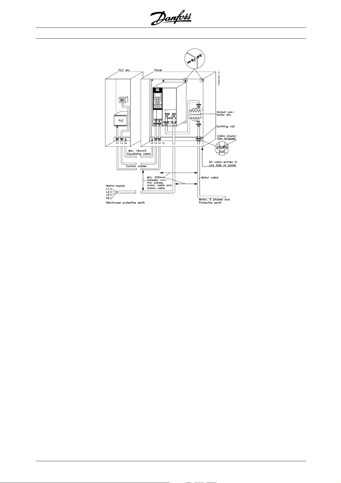
The illustration shows an example of an EMC-correct
electrical installation of an IP 20 frequency converter.
The frequency converter has been fitted in an
installation cabinet with an output contactor and
connected to a PLC, which in this example is installed
in a separate cabinet. Other ways of making the
installation may have as good an EMC performance,
provided the above guide- lines to engineering practice
are followed. Please note that when unscreened
cables and control wires are used, some emission
MG.70.A1.02 - VLT is a registered Danfoss trademark
29
Page 30
VLT® 7000 Booster
30
MG.70.A1.02 - VLT is a registered Danfoss trademark
Page 31

■Use of EMC-correct cables
Braided screened/armoured cables are recommended
to optimise EMC immunity of the control cables and
the EMC emission from the motor cables.
The ability of a cable to reduce the in- and outgoing
radiation of electric noise depends on the switching
impedance (Z
). The screen of a cable is normally
T
designed to reduce the transfer of electric noise;
however, a screen with a lower Z
effective than a screen with a higher Z
is rarely stated by cable manufacturers, but
Z
T
it is often possible to estimate Z
valueismore
T
.
T
by assessing
T
the physical design.
VLT® 7000 Booster
ZTcan be assessed on the basis of the following factors:
- The contact resistance between the individual
screen conductors.
- The screen coverage, i.e. the physical area of the
cable covered by the screen - often stated as a
percentage value. Should be min. 85%.
- Screen type, i.e. braided or twisted pattern.
Aluminium-clad with copper wire.
Twisted copper wire or armoured steel wire cable.
Single-layer braided copper wire with varying
percentage screen coverage.
Double-layer braided copper wire.
Twin layer of braided copper wire with a magnetic,
screened/armoured intermediate layer.
Cable that runs in copper tube or steel tube.
Lead cable with 1.1 mm wall thickness with full
coverage.
Installation
MG.70.A1.02 - VLT is a registered Danfoss trademark
31
Page 32

■Electrical installation - earthing of control cables
Generally speaking, control cables must be braided
screened/armoured and the screen must be
connected by means of a cable clamp at both
ends to the metal cabinet of the unit.
VLT® 7000 Booster
Correct earthing
Control cables and cables for serial communication
must be fitted with cable clamps at both ends to
ensure the best possible electrical contact
The drawing below indicates how correct earthing is
carried out and what to be done if in doubt.
Wrong earthing
Do not use twisted cable ends (pigtails), since these
increase the screen impedance at high frequencies.
Protection with respect to earth potential
between PLC and VLT
If the earth potential between the frequency converter
and the PLC (etc.) is different, electric noise may
occur that will disturb the whole system. This
problem can be solved by fitting an equalising cable,
to be placed next to the control cable. Minimum
cable cross-section: 16 mm2.
For 50/60 Hz earth loops
If very long control cables are used, 50/60 Hz earth
loops may occur. This problem can be solved by
connecting one end of the screen to earth via a
100nF capacitor (keeping leads short).
Cables for serial communication
Low-frequency noise currents between two frequency
converters can be eliminated by connecting one end of
the screen to terminal 61. This terminal is connected
to earth via an internal RC link. It is recommended
to use twisted-pair cables to reduce the differential
mode interference between the conductors.
32
MG.70.A1.02 - VLT is a registered Danfoss trademark
Page 33

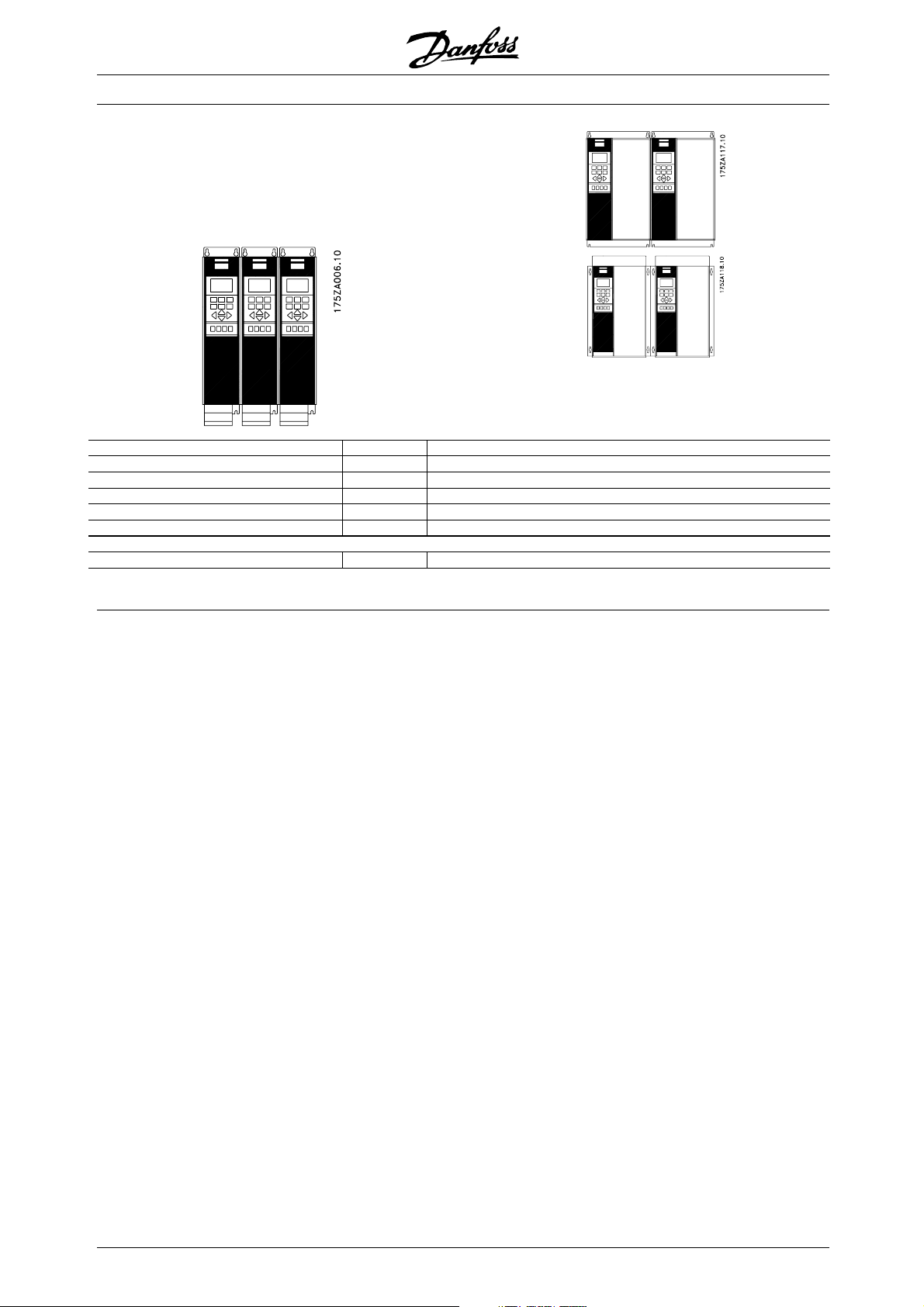
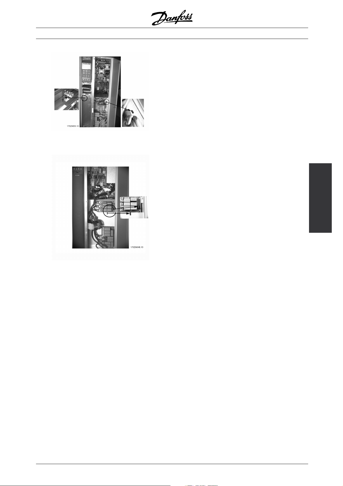
■Electrical installation, enclosures
VLT® 7000 Booster
Bookstyle IP 20
VLT 7002-7011, 380-460 V
Compact IP 20
VLT 7002-7011, 380-460 V
Installation
Compact IP 20
VLT 7016-7072, 380-460 V
MG.70.A1.02 - VLT is a registered Danfoss trademark
33
Page 34

■Electrical installation, power cables
VLT® 7000 Booster
Compact IP 20
VLT 7002-7011, 380-460 V
Bookstyle IP 20
VLT 7002-7011, 380-460 V
IP 20
VLT 7016-7072, 380-460 V
34
MG.70.A1.02 - VLT is a registered Danfoss trademark
Page 35

VLT® 7000 Booster
■Tightening-up torque and screw sizes
The table shows the torque required when
fitting terminals to the frequency converter. For
VLT 7002-7072, 380-460 V the cables must
be fastened with screws.
These figures apply to the following terminals:
Mains terminals (Nos.) L1, L2, L3
Motor terminals (Nos.) U, V, W
Earth terminal (Nos.) 94, 95, 99
VLT type
3 x 380-460 V
VLT 7002-7011 0.5-0.6 Nm M3
VLT 7016-7027 1.8 Nm (IP 20) M4
VLT 7032-7052 3.0 Nm (IP 20) M5
VLT 7062-7072 6.0 Nm M6
1. Loadsharing terminals 14 Nm/M6, 5 mm Allen key
3. Allen screws (hexagon)
4. Loadsharing terminals 9.5 Nm/M8 (bolt)
Tightening-up
torque
91, 92, 93
96, 97, 98
Screw/bolt
size
delta-connected (380/660 V,
/Y). The correct
connection and voltage can be read from
the motor nameplate.
NB!:
In older motors without phase coil insulation,
a LC filter should be fitted to the frequency
converter output.
Allen
key
size
3)
4mm
3)
5mm
Installation
■Mains connection
Mains must be connected to terminals
91, 92, 93 Mains voltage 3 x 380-460 V
NB!:
Check that the mains voltage fits the mains
voltage of the frequency converter, which
can be seen from the nameplate.
See Technical data for correct sizing of cable
cross-sections.
■Motor connection
The motor must be connected to terminals 96,
97, 98. Earth to terminal 94/95/99.
Nos.
96. 97. 98
U, V, W
No. 94/95/99 Earth connection
Motor voltage 0-100 % of mains voltage
See Technical data for correct sizing of cable
cross-sections.
All types of three-phase asynchronous standard motors
can be used with a VLT 7000 Booster unit.
Small-size motors are normally star-connected.
(220/380 V,
MG.70.A1.02 - VLT is a registered Danfoss trademark
/Y). Large-size motors are
35
Page 36

VLT® 7000 Booster
■Direction of motor rotation
The factory setting is for clockwise rotation with the
frequency transformer output connected as follows.
Terminal 96 connected to U-phase
Terminal 97 connected to V-phase
Terminal 98 connected to W-phase
If it is necessary to break the screen to install a motor
isolator or motor contactor, the screen must be
continued at the lowest possible HF impedance.
The direction of motor rotation can be changed by
switching two phases in the motor cable.
■Motor cables
See Technical data for correct sizing of motor
cable cross-section and length.
Always comply with national and local regulations
on cable cross-sections.
NB!:
If an unscreened cable is used, some
EMC requirements are not complied with,
see EMC test results.
If the EMC specifications regarding emission are
to be complied with, the motor cable must be
screened, unless otherwise stated for the RFI filter
in question. It is important to keep the motor cable
as short as possible so as to reduce the noise level
and leakage currents to a minimum.
The motor cable screen must be connected to the
metal cabinet of the frequency converter and to the
metal cabinet of the motor. The screen connections
are to be made with the biggest possible surface (cable
clamp). This is enabled by different installation devices
in the differentT frequency converters. Mounting with
twisted screen ends (pigtails) is to be avoided, since
these spoil the screening effect at higher frequencies.
36
MG.70.A1.02 - VLT is a registered Danfoss trademark
Page 37

VLT® 7000 Booster
■Motor thermal protection
The electronic thermal relay in UL-approved frequency
converters has received UL-approval for single motor
protection, as long as parameter 117 Motor thermal
protection has been set to ETR Trip and parameter 105
Motor current I
, has been programmed for the rated
VLT,N
motor current (can be read from the motor nameplate).
■Earth connection
Since the leakage currents to earth may be higher
than 3.5 mA, the frequency converter must always
be earthed in accordance with applicable na-tional
and local regulations. In order to ensure good
mechanical connection of the earth cable, its cable
cross-section must be at least 10 mm
2
. For added
security, an RCD (Residual Current Device) may be
installed. This ensures that the frequency converter
will cut out if the leakage currents get too high.
See RCD instructions MI.66.AX.02.
■Control card
All terminals for the control cables are located under
the protective cover of the frequency converter. The
protective cover (see drawing below) can be removed
by means of a pointed object - a screwdriver or similar.
Installation
■DC bus connection
The DC bus terminal is used for DC back-up,
with the intermediate circuit being supplied
from an external DC source.
Terminal nos. 88, 89
Contact Danfoss if you require further information.
DC bus connection is not available in
VLT 7002-7011, 380-460 V
■High-voltage relay
The cable for the high-voltage relay must be connected
to terminals 01, 02, 03. The high-voltage relay is
programmed in parameter 323, Relay 1, out-put.
No. 1 Relay ouput 1
1+3 break, 1+2 make
Max 240 V AC, 2 Amp
Min. 24 V DC 10 mA or
24 V AC, 100 mA
Max Cross-section: 4 mm
To rq ue : 0.5 -0 .6 N m
Screw size: M3
MG.70.A1.02 - VLT is a registered Danfoss trademark
2
/10 AWG
37
Page 38

■Electrical installation, control cables
Torque: 0.5-0.6 Nm
Screw size: M3
Generally speaking, control cables must be screened/
armoured and the screen must be connected by means
of a cable clamp at both ends to the metal cabinet of
the unit (see Earthing of screened/ armoured control
cables). Normally, the screen must also be connected
to the body of the controlling unit (follow the instructions
for installation given for the unit in question).
If very long control cables are used, 50/60 Hz
earth loops may occur that will disturb the whole
system. This problem can be solved by connecting
one end of the screen to earth via a 100nF
condenser (keeping leads short).
■Electrical installation, control cables
Max. control cable cross section: 1.5 mm
2
/16 AWG
Torque: 0.5-0.6 Nm
Screw size: M3
See Earthing of screened/armoured control cables
for correct termination of control cables.
VLT® 7000 Booster
No. Function
04, 05 Relay output 2 can be used for indicating
status and warnings.
12, 13 Voltage supply to digital inputs. For the 24 V
DC to be used for digital inputs, switch 4 on
thecontrolcardmustbeclosed,position"on".
16-33 Digital inputs. See parameters 300-307 Digital
inputs.
20 Ground for digital inputs.
39 Ground for analogue/digital outputs. Must
be connnected to terminal 55 by means of
athree-wiretransmitter. SeeExamples of
connection.
42, 45 Analogue/digital outputs for indicating
frequency, reference, current and torque. See
parameters 319-322 Analogue/digital outputs.
50 Supply voltage to potentiometer and thermistor
10 V DC.
53, 54 Analogue voltage input, 0 - 10 V DC.
55 Ground for analogue voltage inputs.
60 Analogue current input 0/4-20 mA. See
parameters 314-316 Terminal 60.
61 Termination of serial communication. See
Earthing of screened/armoured control cables.
This terminal is not normally to be used.
68, 69 RS 485 interface, serial communication.
Where the frequency converter is connected
to a bus, switches 2 and 3 (switches 1- 4 see next page) must be closed on the first and
the last frequency converter. On the remaining
frequency converters, switches 2 and 3 must
be open. The factory setting is closed (position
on).
38
MG.70.A1.02 - VLT is a registered Danfoss trademark
Page 39

VLT® 7000 Booster
■Switches 1-4
The dipswitch is located on the control card. It is used
for serial communication and external DC supply.
The switching position shown is the factory setting.
Switch 1 has no function.
Switches 2 and 3 are used for terminating an RS-485
interface to the serial communication bus
NB!:
When the frequency converter is the
last device on the serial communication bus,
switches 2 and 3 must be ON in that designated
VLT. A
ny other VLTs on the serial communication bus
must have switches 2 and 3 set to OFF.
NB!:
Please note that when Switch 4 is in position
"OFF," the external 24 V DC supply is galvanically
isolated from the frequency converter.
first or
In order to avoid potential equa
screen, the cable screen can be earthed via terminal
61, which is connected to the frame via an RC-link.
lizing currents in the
Installation
■Bus connection
The serial bus connection in accordance with the RS
485 (2-conductor) norm is connected to terminals
68/69 of the frequency converter (signals P and N).
Signal P is the positive potential (TX+,RX+), while
signal N is the negative potential (TX-,RX-).
If more than one frequency converter is to be connected
to a given master, use parallel connections.
MG.70.A1.02 - VLT is a registered Danfoss trademark
39
Page 40

■Control unit LCP
The front of the frequency converter features a
control panel - LCP(Local Control Panel). This is a
complete interface for operation and programming
of the frequency converter.
The control panel is detachable and can - as an
alternative - be installed up to 3 metres away from
the frequency converter, e.g. on the front panel,
by means of a mounting kit option.
The functions of the control panel can be
divided into five groups:
1. Display
2. Keys for changing display mode
3. Keys for changing program parameters
4. Indicator lamps
5. Keys for local operation
All data are indicated by means of a 4-line alphanumeric
display, which, in normal operation, is able to show
4 operating data values and 3 operating condition
values continuously. During programming, all the
information required for quick, effective parameter
Setup of the frequency converter will be displayed.
As a supplement to the display, there are three
indicator lamps for voltage (ON), warning (WARNING)
and alarm (ALARM), respectively.
All frequency converter parameter Setups can be
changed immediately via the control panel, unless this
function has been programmed to be Locked [1] via
parameter 016 Lock for data change or via a digital
input, parameters 300-307 Data change lock.
VLT® 7000 Booster
■Control keys for parameter setup
The control keys are divided into functions. This means
that the keys between display and indicator lamps
are used for parameter Setup, including se
display indication during normal operation.
lecting the
[DISPLAY MODE] is used for selecting
theindicationmodeofthedisplayor
whenreturningtotheDisplaymode
from either the Quick menu or the
Extend menu mode.
40
MG.70.A1.02 - VLT is a registered Danfoss trademark
Page 41

[QUICK MENU] gives access to the
parameters used for the Quick menu.
It is possible to switch between the
Quick menu and the Extend menu
modes.
VLT® 7000 Booster
■Local control
Underneath the indicator lamps are keys
for local control.
[EXTEND MENU] gives access to all
parameters. It is possible to switch
between the Extend menu and the
Quick menu modes.
[CHANGE DATA] is used for changing
a setting selected either in the Extend
menu or the Quick menu mode.
[CANCEL] is used if a change of
the selec-ted parameter is not to be
carried out.
[OK] is used for confirming a change
of the parameter selected.
[+/-] is used for selecting parameters
and for changing a chosen parameter.
These keys are also used to change
the local reference.
In addition, the keys are used in
Display mode to switch between
operation variable readouts.
[<>] is used when selecting a
parameter group and for moving
the cursor when changing numerical
values.
■Indicator lamps
At the bottom of the control panel is a red
alarm lamp and a yellow warning lamp, as well
as a green volta
If certain threshold values are exceeded, the
alarm and/ or warning lamp is activated, and a
status or alarm text is displayed.
NB!:
The voltage indicator lamp is activated when
the frequency converter receives voltage.
ge LED.
[HAND START] is used if the frequency
converter is to be controlled via the
control unit. The frequency converter
will start the motor, since a start
command is given by means of [HAND
START].
On the control terminals, the following
control signals will still be active when
[HAND START] is activated:
• Hand start - Off stop - Auto start
• Safety Interlock
• Reset
• Coasting stop inverse
• Reversing
• Setup select lsb - Setup select msb
• Jog
• Run permissive
• Lock for data change
• Stop command from serial
communication
NB!:
If parameter 201 Output frequency low limit
is set to an output frequency greater than
f
MIN
0 Hz, the motor will start and ramp up to this
frequency when [HAND START] is activated.
[OFF/STOP] is used for stopping the
connected motor. Can be selected as
Enable [1] or Disable [0] via parameter
013. If the stop function is activated,
line 2 will flash.
[AUTO START] is used if the frequency
converter is to be controlled via
the control terminals and/or serial
communication. When a start signal is
active on the control terminals and/or
the bus, the frequency converter will
start.
NB!:
An active HAND-OFF-AUTO signal via the digital
inputs will have higher priority than the control
keys [HAND START]-[AUTO START].
Programming
MG.70.A1.02 - VLT is a registered Danfoss trademark
41
Page 42

[RESET] is used for resetting the
frequency converter after an alarm
(trip). Can be selected as Enable [1]
or Disable [0] via parameter 015 Reset
on LCP.
See also List of warnings and alarms.
VLT® 7000 Booster
■Display mode, cont.
Three operating data values can be shown in the first
display line, while one operating variable can be shown
in the second display line. To be programmed via
parameters 007, 008, 009 and 010 Display read-out.
• Status line (4th line):
■Display mode
In normal operation, any 4 different operating variables
can be indicated continuously: 1.1 and 1.2 and
1.3 and 2. The present operating status or alarms
and warnings that have arisen are shown in line 2
in the form of a number. In the case of alarms, the
alarm in question will be shown in lines 3 and 4,
accompanied by an explanatory note. Warnings will
flash in line 2, with an explanatory note in line 1. In
addition, the display shows the active Setup.
The arrow indicates the direction of rotation; here the
frequency converter has an active reversing signal. The
arrow body disappears if a stop command is given or if
the output frequency falls below 0.01 Hz. The bottom
line gives the status of the frequency converter.
The scroll list on the next page gives the operating
data that can be shown for variable 2 in display mode.
Changes are made via the [+/-] keys.
1st line
2nd line
VAR 1.1 VAR 1.2 VAR 1.3
SETUP
VAR 2
1
3rd line
80.0% 5.08A 2.15kW
SETUP
40.0Hz
AUTO REMOTE RUNNING
HAND LOCAL STOP
OFF
LOCAL STOPRAMPING
HAND JOGGING
.
.
.
The left part of the status line indicates the
control ele-ment of the frequency converter that is
active. AUTO means that control is via the control
terminals, while HAND indicates that control is via
the local keys on the control unit.
OFF means that the frequency converter ignores all
195NA113.10
control commands and stops the motor.
The centre part of the status line indicates the
refe-rence element that is active. REMOTE means
that the reference from the control terminals is active,
while LOCAL indicates that the reference is determined
via the [+/-] keys on the control panel.
1
.
STAND BY
175ZA701.10
4th line
42
STATUS
The last part of the status line indicates the current
status, for example "Running", "Stop" or "Alarm".
■DisplaymodeI:
VLT 7000 Booster offers different display modes depending on the mode selected for the frequency
converter. The figure on the next page shows the way
to navigate between different display modes.
Below is a display mode, in which the frequency
converter is in Auto mode with remote reference
at an output frequency of 40 Hz.
In this display mode, reference and control are
determined via the control terminals.
Thetextinline1givestheoperatingvariable
showninline2.
MG.70.A1.02 - VLT is a registered Danfoss trademark
Page 43

VLT® 7000 Booster
FREQUENCY
40.0Hz
AUTO REMOTE RUNNING
Line 2 gives the current output frequency
and the active Setup.
Line 4 says that the frequency converter is in Auto mode
with remote reference, and that the mo tor is running.
■Display mode II:
This display mode makes it possible to have three
operating data values displayed at the same time in
line 1. The operating data values are determined
in parameters 007-010 Display readout.
100% 7.8A 5.9kW
50.0Hz
SETUP
1
SETUP
1
175ZA683.10
175ZA685.10
USE +/- 40Hz
40.0Hz
----60
0
HAND LOCAL RUNNING
SETUP
1
176FA156.10
AUTO REMOTE RUNNING
■Display mode III:
This display mode is active as long as the [DISPLAY
MODE] key is kept depressed. In the first line,
operating data names and units of operating data
are displayed. In the second line, operating data 2
remains unchanged. When the key is released, the
different operating data values are shown.
REF% CURR.A.POW.,KW
SETUP
50.0Hz
AUTO REMOTE RUNNING
■DisplaymodeIV:
This display mode is only active in connection with
local reference, see also Reference handling.Inthis
display mode, the reference is determined via the
[+/-] keys and control is carried out by means of the
keys underneath the indicator lamps. The first line
indicates the required reference. The third line gives
the relative value of the present output frequency at
any given time in relation to the maximum frequency.
The display is in the form of a bar graph.
1
Programming
175ZA695.10
MG.70.A1.02 - VLT is a registered Danfoss trademark
43
Page 44

■Navigation between display modes
Press briefly
HAND LOCAL RUNNING
USE +/- 40Hz
VLT® 7000 Booster
FREQUENCY
40.0Hz
AUTO REMOTE RUNNING
▲▲
▲
▲▲
Display mode I
With remote
reference
▲▲
▲
▲▲
▲▲
▲
▲▲
80% 7,8A 5,9 KW
40.0Hz
0 ---- 60
HAND LOCAL RUNNING
Display mode IV
175ZA697.10
SETUP
1
▲▲
▲▲
▲
With local reference
Keep the [DISPLAY
MODE] key down
40.0 Hz
AUTO REMOTE RUNNING
Display mode II
▲▲
▲
▲▲
REF% CURR.A POW.,KW
40.0 Hz
AUTO REMOTE RUNNING
Display mode III
44
MG.70.A1.02 - VLT is a registered Danfoss trademark
Page 45

■Changing data
Regardless of whether a parameter has been
selected under the Quick menu or the Extended
menu, the procedure for changing data is the same.
Pressing the [CHANGE DATA] key allows change
of the selected parameter, and the underlining
in line 4 will flash on the display.
The procedure for changing data depends on whether
the selected parameter represents a numerical
data value or a functional value.
If the chosen parameter represents a numeric data
value, the first digit can be changed by means of
the [+/-] keys. If the second digit is to be changed,
first move the cursor by using the [<>] keys, then
change the data value using the [+/-] keys.
FREQUENCY
24.2 Hz
205 MAX. REFERENCE
000060,000 Hz
5
SETUP
1
175ZA698.10
VLT® 7000 Booster
FREQUENCY
SETUP
50.0
209 JOG FREQUENCY
1
0.0 Hz
The chosen digit flashes. The bottom display
line shows the data value that will be entered
(saved) when signing off with [OK].
■Changing of data value, step-by-step
Certain parameters can be changed both step by
step and infinitely variably. This applies to Motor
power (parameter 102), Mot or voltage (parameter
103) and Motor frequency (parameter 104).
This means that the parameters are changed
bothasagroupofnumericdatavaluesandas
numeric data values infinitely variably.
SETUP
1
1
175ZA700.10
The selected digit is indicated by a flashing cursor. The
bottom display line gives the data value that will be
entered (saved) when signing off by pressing the [OK]
button. Use [CANCEL] to cancel the change.
If the selected parameter is a functional value,
the selected text value can be changed by
means of the [+/-] keys.
MOTOR CURRENT
3.90 A
210 REFERENCE TYPE
SUM
SETUP
1
175ZA689.10
The functional value flashes until signing off by pressing
the [OK] button. The functional value has now been
selected. Use [CANCEL] to cancel the change.
■Infinitely variable change of numeric data value
If the chosen parameter represents a numeric data
value, a digit is first selec
ted by means of the [<>] keys.
■Manual initialisation
Disconnect from mains and hold the [DISPLAY MODE]
+ [CHANGE DATA] + [OK] keys down while at the
same time reconnecting the mains supply. Release
the keys; the frequency converter has now been
programmed for the factory setting.
The following parameters are not zeroed by means of manual
initialisation:
Parameter 500, Protocol
600, Operating hours
601, hours run
602, kWh counter
603, Number of power-ups
604, Number of overtemperatures
605, Number of overvoltages
It is also possible to carry out initialisation via
parameter 620 Operating mode.
Programming
FREQUENCY
SETUP
50.0 Hz
209 JOG FREQUENCY
0
9 .0 Hz
SETUP
1
1
175ZA699.10
Then the chosen digit is changed infinitely by
means of the [+/-] keys:
MG.70.A1.02 - VLT is a registered Danfoss trademark
45
Page 46

■Quick Menu
The QUICK MENU key gives access to 41 of
the most important setup parameters of the
drive. After programming, the drive will, in many
cases, be ready for operation.
VLT® 7000 Booster
Quick Menu
Number
1 102 Motor Power KW/HP 1,1-55/1,5-75 kW
2 103 Motor Voltage Volt 380-460
3 104 Motor Frequency Hz 50/60 Hz 50 Hz
4 105 Motor Current Amps 0-Ivlt,max 5 106 Rated motor speed RPM 1200 - f m,n x 60 6 201 Min. Frequency Hz 0,0 - fmax 20 Hz
7 202 Max. Frequency Hz fmin - 120/1000 50 Hz
8 206 Ramp up time seconds 1-60 See table below
9 207 Ramp down time Seconds 1-60 See table below
10 415 Pressure unit Bar
11 413 Minimum Feedback Par. 415 999.999,999-FBmax 0.000
12 414 Maximum Feedback Par. 415 FBmin - 999.999,999 100.000
13 227 Warning Low Feedback Par. 415 999.999,999-FBhigh -999.999.999
14 228 Warning High Feedback Par. 415 FBlow - 999.999,999 999.999.999
15 204 Minimum reference Par. 415 Min. feedback - Max. reference 0.000
16 205 Maximum reference Par. 415 Min. reference - Max. feedback 50.000
17 700 Cascade mode 1-14 1
18 701 Pump Combination DOM
19 702 Staging bandwidth % 0-100 5
20 703 SBW destage delay Sec. 0-3000 10
21 704 SBW stage delay Sec. 0-3000 10
22 705 Override bandwidth % 0-100 (100=Off) Off
23 706 Override timer Sec. 0-300 10
24 707 Destage by timer Sec. 0-301 (301=Off) Off
25 708 Staging frequency % 0-100% of f
26 709 Destaging frequency % 0-100% of f
27 710 Delay before running on mains ms 0-2000 500
28 711 Sleep/AUX timer Sec. 0-300 (301 = Off) DOM
29 712 Sleep/AUX frequency Hz Par. 201 - Par. 713 20 Hz
30 713 Wakeup/disable AUX -
31 714 Boost setpoint % 1-200% of Setpoint 1 100%
32 418 Setpoint 1 (H0) Par. 415 Par. 413-Par. 414 0.000
33 419 Setpoint 2 (H1) Par. 415 Par. 413-Par. 414 0.000
34 719 Pump enable Indexed par. 0-1 1
35 720 Pump running hours Hours 0,0-999.999,9 36 721 Setpoints Par. 415 0,0-999.999,9 37 420 Normal/inverse control Normal/inverse Normal
38 422 PID start up frequency Hz f
39 427 PID Lowpass filter time Sec. 0.01-10.00 0.2
40 423 PID Proportional Gain Factor 0.00-10.00 0.3
41 424 PID Integrator time Sec. 0.01-9999.00 Off
Parameter
number
Name Units Range Factory Setting
1
max
max
Hz Par. 712 - Par. 202 50 Hz
frequency
min-fmax
90
50
2
0
VLT Type Ramp up time
(par.206)
7002-7011 1 sec. 1 sec.
7016-7062 3 sec. 2 sec.
7072 5 sec. 3 sec.
Ramp down time
(par.207)
46
1) Depending on Mode, please refer to par. 700.
2) Depending on Mode, with AUX pump: 150
sec., without AUX pump: OFF.
MG.70.A1.02 - VLT is a registered Danfoss trademark
Page 47
■Parameter Data
Enter or change parameter dataor settings in
accordance with the following procedure.
1. Press Quick Menu key.
2. Use ‘+’ and ‘-’ keys to find parameter
you choose to edit.
3. Press Change Data key.
4. Use ‘+’ and ‘-’ keys to select correct parameter
setting. To move to a different digit within
parameter, use < and > arrows. Flashing cursor
indicates digit selected to change.
5. Press Cancel key to disregard change, or press
OK key to accept change and enter new setting.
Example of Changing Parameter Data
Assume parameter 206, Ramp Up Time, is set at 60
seconds. Change the ramp up time to 100 seconds
in accordance with the following procedure.
1. Press Quick Menu key.
2. Press ‘+’ key until you reach Parameter
206, Ramp Up Time.
3. Press Change Data key.
4. Press < key twice – hundreds digit will flash.
5. Press ‘+’ key once to change hundreds digit to ‘1.’
6. Press > key to change to tens digit.
7. Press ‘-’ key until ‘6’ counts down to ‘0’ and
setting for Ramp Up Time reads ‘100 s.’
8. Press OK key to enter new valueinto drive controller.
VLT® 7000 Booster
NB!:
Programming of extended parameters functions
available through EXTENDED MENU key is
done in accordance with same procedure
as described for Quick Menu functions.
Programming
MG.70.A1.02 - VLT is a registered Danfoss trademark
47
Page 48

VLT® 7000 Booster
■Programming
Using the [EXTEND MENU] key, it
is possible to have access to all
the parameters for the frequency
converter.
■Operation and Display 001-017
This parameter group allows to set up parameters
such as language, display readout and the possibility of
making the function keys on the control unit inactive.
001 Language
(LANGUAGE)
Value:
✭English (ENGLISH)
German (DEUTSCH)
French (FRANCAIS)
Danish (DANSK)
Spanish (ESPAÑOL)
Italian (ITALIANO)
Swedish (SVENSKA)
Dutch (NEDERLANDS)
Portuguese (PORTUGUESA)
Finnish (SUOMI)
[0]
[1]
[2]
[3]
[4]
[5]
[6]
[7]
[8]
[9]
By means of parameter 004 LCP copy,allSetups
can be transferred from one frequency converter
to another by moving the control panel. First all
parameter values are copied to the control panel. This
can then be moved to another frequency converter,
where all parameter values can be copied from the
control unit to the frequency converter.
002 Active Setup
(ACTIVE SETUP)
Value:
Factory Setup (FACTORY SETUP)
✭Setup 1 (SETUP 1)
Function:
The choice in this parameter defines the Setup number
you want to control the functions of the frequency
converter. In addition, a pre-programmed Setup
called the Factory Setup exists. This only allows
specific parameters to be changed.
Description of choice:
Factory Setup [0] contains the parameter values pre-set
at the factory. Can be used as a data source if the
other Setups are to be returned to a common state. In
this case Factory Setup is selected as the active Setup.
[0]
[1]
State when delivered may vary from factory setting.
Function:
Thechoiceinthisparameterdefinesthelanguage
to be used on the display.
Description of choice:
There is a choice of the languages indicated.
■The Setup configuration
The frequency converter has four
Setups) that can be programmed independently
of each other. The active Setup can be selected
in parameter 002 Active Setup.
number will be shown in the display under "Setup".
It is also possible to set the frequency converter to
Multi-Setup to allow switc
digital inputs or serial communication.
Setup shifts can be used in systems where, one Setup
is used during the day and an
Parameter 003 Copying of Setups enables copying
from one Setup to another.
hing of Setups with the
Setups (parameter
The active Setup
other at night.
✭ = factory setting. () = display text [] = value for use in communication via serial communication port
48
MG.70.A1.02 - VLT is a registered Danfoss trademark
Page 49

004 LCP copy
(LCP COPY)
Value:
✭No copying (NO COPY)
Upload all parameters
(UPLOAD ALL PARAMET.)
Download all parameters
(DOWNLOAD ALL PARAM.)
Download power-independent par.
(DOWNLOAD SIZE INDEP.)
Function:
Parameter 004 LCP copy is used if the integrated
copying function of the control panel is to be used.
This function is used if all parameter Setups are
to be copied from one frequency converter to
another by moving the control panel.
Description of choice:
Select Upload all parameters [1] if all parameter values
aretobetransmittedtothecontrolpanel.
Select Download all parameters [2] if all transmitted
parameter values are to be copied to the frequency
converter onwhich the control panel has beenmounted.
Select Download power-independent par. [3] if only the
power-independent parameters are to be downloaded.
This is used if downloading to a frequency converter
that has a different rated power than the one from
where the parameter Setup originates.
NB!:
Uploading/Downloading can only be carried
out in the Stop mode.
VLT® 7000 Booster
[0]
[1]
[2]
[3]
Programming
■Setup of user-defined readout
Parameter 005 Max. value of user-defined readout
and 006 Unit for user-defined readout allow users
to design their own readout which can be seen
if user-defined readout has been selected under
display readout. The range is set in parameter 005
Max. value of user-defined readoutandtheunitis
determined in parameter 006 Unit for user-defined
readout. The choice of unit decides whether the
ratio between the output frequency and the readout
is a linear, square or cubed ratio.
✭ = factory setting. () = display text [] = value for use in communication via serial communication port
MG.70.A1.02 - VLT is a registered Danfoss trademark
49
Page 50

VLT® 7000 Booster
005 Max. value of user-defined readout
Function:
(CUSTOM READOUT)
Value:
0.01 - 999,999.99
✭ 100.00
Function:
Thisparameterallowsachoiceofthemax. value
of the user-defined readout. The value is calculated
on the basis of the present motor frequency and the
unit selected in parameter 006 Unit for user-defined
readout. The programmed value is reached when
the output frequency in parameter 202 Output
frequency high limit,f
is reached. The unit also
MAX
decides whether the ratio between output frequency
and readout is linear, square or cubed.
Description of choice:
Set the required value for max. output frequency.
Select a unit to be shown in the display in connection
with parameter 005 Max. value of user-defined readout.
006 Unit for user-defined readout
(CUST. READ. UNIT)
✭No unit
1
%
1
rpm
1
ppm
pulse/s
1
l/s
1
l/min
1
l/h
1
kg/s
kg/min
1
kg/h
3/s1
m
3
m
/min
3/h1
m
1
m/s
2
mbar
2
bar
2
Pa
2
kPa
2
MWG
3
kW
1
[0] GPM
[1] gal/s
[2] gal/min
1
[3] gal/h
[4] lb/s
[5] lb/min
[6] lb/h
[7] CFM
1
[8] ft3/s
[9] ft3/min
[10] ft3/h
1
[11] ft3/min
[12] ft/s
[13] in wg
[14] ft wg
[15] PSI
[16] lb/in
[17] HP
[18]
[19]
[20]
1
1
1
1
1
1
1
1
1
1
1
1
1
2
2
2
2
3
Flow and speed units are marked with 1.
Pressure units with 2, and power units with
3. Seefigureinnextcolumn.
[21]
[22]
[23]
[24]
[25]
[26]
[27]
[28]
[29]
[30]
[31]
[32]
[33]
[34]
[35]
[36]
[37]
[38]
If units such as flow or speed units are selected, the
ratio between readout and output frequency
will be a linear one.
If pressure units are selected (bar, Pa, MWG, PSI,
etc.), the ratio will be square. If power units (HP,
kW) are selected, the ratio will be cubed.
The value and the unit are shown in display mode
whenever User-defined readout [10] has been selected
in one of parameters 007-010 Display readout.
Description of choice:
Select the required unit for User-defined read out .
007 Large display readout
(LARGE READOUT)
Value:
Resulting reference [%](REFERENCE [%])
Resulting reference [unit] (REFERENCE [UNIT])
✭Frequency [Hz] (FREQUENCY [HZ])
% of maximum output frequency [%]
(FREQUENCY [%])
Motor current [A] (MOTOR CURRENT [A])
Power [kW] (POWER [KW])
Power [HP] (POWER [HP])
Output energy [kWh] (ENERGI [UNIT])
Hours run [Hours](OURS RUN [H])
User-defined readout [-]
(CUSTOM READ.[UNITS]))
Setpoint 1 [unit](SETPOINT 1 [UNITS])
Setpoint 2 [unit](SETPOINT 2 [UNITS])
Feedback 1 (FEEDBACK 1 [UNITS])
Feedback 2 (FEEDBACK 2 [UNITS])
✭
= factory setting. () = display text [] = value for use in communication via serial communication port
[1]
[2]
[3]
[4]
[5]
[6]
[7]
[8]
[9]
[10]
[11]
[12]
[13]
[14]
50
MG.70.A1.02 - VLT is a registered Danfoss trademark
Page 51

VLT® 7000 Booster
Feedback [unit] (FEEDBACK [UNITS])
Motor voltage [V] (MOTOR VOLTAGE [V])
DC link voltage [V] (DC VOLTAGE [V])
[15]
[16]
[17]
Thermal load, motor [%]
(THERM.MOTOR LOAD [%])
[18]
Thermal load, VLT [%]
(THERM.DRIVE LOAD [%])
[19]
Digital input [Binary code]
(DIGITAL INPUT [BIN])
Analogue input 53 [V] (ANALOG INPUT 53 [V])
Analogue input 54 [V] (ANALOG INPUT 54 [V])
[20]
[21]
[22]
Analogue input 60 [mA]
(ANALOG INPUT 60 [MA])
Relay status [binary code] (RELAY STATUS)
Pulse reference[Hz](PULSE REFERENCE [HZ])
External reference [%] (EXT. REFERENCE [%])
Heat sink temp. [°C] (HEATSINK TEMP [°C])
[23]
[24]
[25]
[26]
[27]
Communication option card warning
(COMM OPT WARN [HEX])
LCP display text (FREE PROG.ARRAY)
Status word (STATUS WORD [HEX])
Control word (CONTROL WORD [HEX])
Alarm word(ALARM WORD [HEX])
[28]
[29]
[30]
[31]
[32]
Function:
This parameter allows a choiceofthedatavalueto
be shown in the display, line 2, when the frequency
converter is turned on. The data values will also be
included in the display mode scroll-list. Parameters
008-010 Small display readout allow a choice of
another three data values, shown in line 1.
See the description of the control unit.
Description of choice:
No readout can only be selected in parameters
008-010 Small display readout.
Resulting reference [%] gives a percentage for
the resulting reference in the range from Minimum
reference,Ref
to Maximum reference, Ref
MIN
MAX
. See also reference handling.
Reference [unit] gives the resulting reference in Hz
in Open loop.InClosed loop, the reference unit is
selected in parameter 415 Process units.
Frequency [Hz] gives the output frequency
from the frequency converter.
% of maximum output frequency [%] is the present
output frequency as a percentage value of parameter
202 Output frequency high limit, f
MAX
.
Motor current [A] states the phase current of the
motor measured as effective value.
Power [kW] states the actual power consumed
by the motor in kW.
Power [HP] states the actual power consumed
by the motor in HP.
Output energy [kWh] states the energy consumed
by the motor since the latest reset was made in
pa-rameter 618 Reset of kWh counter.
Hours run [Hours] states the number of hours
that the motor has run since the latest reset in
parameter 619 Reset of hours-run counter.
User -defined readout [-] is a user-defined value,
calculated on the basis of the present output frequency
and unit, as well as the scaling in parameter 005
Max. value of user-defined readout. Select unit in
parameter 006 Unit for user-defined readout.
Setpoint 1 [unit] is the programmed setpoint
value in parameter 418 Setpoint 1.Theunit
is decided in parameter 415 Process units .
See also Feedback handling.
Setpoint 2 [unit] is the programmed setpoint value
in parameter 419 Setpoint 2. The unit is decided
in parameter 415 Process units.
Feedback 1 [unit] gives the signal value of the resulting
feedback 1 (Term. 53). The unit is decided in parameter
415 Process units. See also F eedback handling .
Feedback 2 [unit] gives the signal value of the
resulting feedback 2 (Term. 53). The unit is decided
in parameter 415 Process units.
Feedback [unit] gives the resulting signal value
using the unit/scaling selected in parameter 413
Minimum feedback,FB
and 415 Process units .
FB
MAX
, 414 Maximum feedback,
MIN
Motor voltage [V] states the voltage supplied
to the motor.
DC link voltage [V] states the intermediate circuit
voltage in the frequency converter.
Thermal load, motor [%] states the calculated/
estimated thermal load on the motor. 100%
is the cut-out limit. See also parameter 117
Motor thermal protection.
Thermal load, VLT [%] states the calculated/
estimated thermal load on the frequency converter.
100% is the cut-out limit.
Digital input [Binary code] states the signal status
from the 8 digital inputs (16, 17, 18, 19, 27, 29, 32
and 33). Terminal 16 corresponds to th
ebitatthefar
left. ‘0’ =nosignal,‘1’ = connected signal.
Analogue input 53 [V] states the voltage
value on terminal 53.
Analogue input 54 [V] states the voltage
value on terminal 54.
Analogue input 60 [mA] states the vol
tage
value on terminal 60.
Relaystatus[binarycode]indicates the status of
each relay. The left (most significa
nt) bit indicates
relay 1 followed by 2 and 6 through 9. A "1" indicates
the relay is active, a "0" indicates inactive. Paramater
007 uses an 8-bit word with th
e last two positions
Programming
✭
= factory setting. () = display text [] = value for use in communication via serial communication port
MG.70.A1.02 - VLT is a registered Danfoss trademark
51
Page 52

VLT® 7000 Booster
not used. Relays 6-9 are provided with the cascade
controller and four relay option cards
Pulse reference [Hz] states a pulse frequency in
Hz connected to terminal 17 or terminal 29.
External reference [%] gives the sum of the external
references as a percentage (the sum of analogue/
pulse/serial communication) in the range from Minimum
reference,Ref
to Maximum reference,Ref
MIN
MAX
.
Heat sink temp. [°C] states the present heat sink
temperature of the frequency converter. The cut-out
limit is 90 ± 5°C; cutting back in occurs at 60 ± 5°C.
Communication option card warning [Hex] gives a
warning word if there is a fault on the communication
bus. This is only active if communication options
have been installed. Without communication
options, 0 Hex is displayed.
LCP display text shows the text programmed in
parameter 533 Display text 1 and 534 Display text
2 via LCP or the serial communication port.
LCP procedure for entering text
After selecting Display Text in parameter 007, select
display line parameter (533 or 534) and press the
CHANGE DATA key. Enter text directly into the
selected line by using UP, DN & LEFT, RIGHT arrow
keys on the LCP. The UP and DN arrow keys scroll
through the available characters. The Left and Right
arrow keys move the cursor through the line of text.
To lock in the text, press the OK key when the line of text
is completed. The CANCEL key will cancel the text.
The available characters are:
ABCDEFGHIJKLMNOPQRSTUVWXYZ
ЖШЕДЦЬЙМЩи./-()0123456789’space’
’space’ is the default value of parameter 533 &
534. To erase a character that has been entered,
it must be replaced with ’space’.
Status word displays the actual drive status
word (see parameter 608).
Control word displays the actual control word
(see parameter 607).
Alarm word displays the actual alarm word.
This is a useful function, i.a. when setting the
PID regulator, in order to see how the process
reacts to a change of reference.
For display read-outs, press the [DISPLAY MODE]
button. Data option LCP display text [29] cannot
be selected with Small display readout .
Description of choice:
There is a choice of 31 different data values, see
parameter 007 Large display readout.
008 Small display readout 1.1
(SMALL READOUT 1)
Value:
See parameter 007 Large display readout
✭ Reference [Unit]
[2]
Function:
This parameter enables a choice of the first of three data
values to be shown on the display, line 1, position 1.
✭ = factory setting. () = display text [] = value for use in communication via serial communication port
52
MG.70.A1.02 - VLT is a registered Danfoss trademark
Page 53

009 Small display readout 1.2
(SMALL READOUT 2)
Value:
See parameter 007 Large display readout
✭Motorcurrent [A]
Function:
See the functional description for parameter 008 Small
display readout. Data option LCP display text [29]
cannot be selected with Small display readout .
Description of choice:
There is a choice of 31 different data values, see
parameter 007 Large display readout.
010 Small display readout 1.3
(SMALL READOUT 3)
Value:
Se parameter 007 Large display readout
✭Power [kW]
Function:
See the functional description for parameter 008 Small
data readout. Data option LCP display text [29] cannot
be selected with Small display readout .
Description of choice:
There is a choice of 31 different data values, see
parameter 007 Large display readout.
[5]
[6]
VLT® 7000 Booster
Function:
This parameter allows selection/deselection of the
Hand start key on the control panel.
Description of choice:
If Disable [0] is selected in this parameter, the
[HAND START] key will be inactive.
013 OFF/STOP on LCP
(STOP BUTTON)
Value:
Disable(DISABLE)
✭Enable (ENABLE)
Function:
This parameter allows selection/deselection of the
local stop key on the control panel.
Description of choice:
If Disable [0] is selected in this parameter, the
[OFF/ STOP] key will be inactive.
NB!:
If Disable is selected, the motor cannot be
stopped by means of the [OFF/STOP] key.
014 Auto start on LCP
(AUTO START BTTN)
Value:
Disable(DISABLE)
✭Enable (ENABLE)
[0]
[1]
Programming
[0]
[1]
011 Unitoflocalreference
(UNIT OF LOC REF)
Value:
Hz (HZ)
✭% of output frequency range (%) (% OF FMAX)
Function:
This parameter decides the local reference unit.
Description of choice:
Choose the required unit for local reference.
012 Hand start on LCP
(HAND START BTTN)
Value:
Disable (DISABLE)
✭Enable (ENABLE)
✭
= factory setting. () = display text [] = value for use in communication via serial communication port
MG.70.A1.02 - VLT is a registered Danfoss trademark
[0]
[1]
[0]
[1]
Function:
This parameter allows selection/deselection of the
auto start key on the control panel.
Description of choice:
If Disable [0] is selected in this parameter, the
[AUTO START] key will be inactive.
015 Reset on LCP
(RESET BUTTON)
Value:
Disable(DISABLE)
✭Enable (ENABLE)
Function:
This parameter allows selection/deselection of the
reset key on the control panel.
[0]
[1]
53
Page 54

VLT® 7000 Booster
Description of choice:
If Disable [0] is selected in this parameter, the
[RESET] key will be inactive.
NB!:
Only select Disable [0] if an external reset signal
has been connected via the digital inputs.
016 Lock for data change
(DATA CHANGE LOCK)
Value:
✭Not locked (NOT LOCKED)
Locked (LOCKED)
Function:
This parameter allows the control panel to be "locked",
which means that it is not possible to carry out
data modifications via the control unit.
Description of choice:
If Locked [1] is selected, data modifications in the
parameters cannot be made, although it will still
be possible to carry out data modifications via the
bus. Parameters 007-010 Display readout can
be changed via the control panel.
It is also possible to lock for data modifications in
these parameters by means of a digital input, see
parameters 300-307 Digital inputs.
NB!:
If [HAND START] or [AUTO START] cannot
be activated by the keys on the control
panel (see parameter 012/014 Hand/Auto
start on LCP) the motor will not be able to
restart if OFF/Stop [1] is selected. If Handstart
or Autostart has been programmed for activation
via the digital inputs, the motor will not be able
to restart if OFF/Stop [1] is selected.
[0]
[1]
017 Operating state at power up, local control
(POWER UP ACTION)
Value:
✭Auto restart (AUTO RESTART)
OFF/Stop (OFF/STOP)
Function:
Setting of the desired operating mode when the
mains voltage is reconnected.
Description of choice:
Auto restart [0] is selected if thefrequency converter is to
start up in the same start/stop condition as immediately
before power to the frequency converter is cut off.
OFF/Stop [1] is selected if the frequency converter
is to remain stopped when the mains voltage is
connected, until a start command is active. To
restart, activate the key [HAND START] or [AUTO
START] b
y using the control panel.
[0]
[1]
✭ = factory setting. () = display text [] = value for use in communication via serial communication port
54
MG.70.A1.02 - VLT is a registered Danfoss trademark
Page 55

■Load and Motor 100-117
This parameter group allows
the con-figuration of regulation
parameters and the choice of
torque characteristics to which
the frequency converter is to be
adapted.
The motor nameplate data must
be
set and automatic motor adaptation can be carried
out. In addition, DC brake parameters can be set
and the motor thermal protection can be activated.
■Configuration
The selection of configuration and torque characteristics
influences the parameters that can be seen in the
display. If Open loop [0] is selected, all parameters
relating to PID regulation will be hidden.
Consequently, the user is only able to see
the parameters that are of significance for
a given application.
VLT® 7000 Booster
101 Torque characteristics
(VT CHARACT)
Value:
✭Automatic Energy Optimisation
(AEO FUNCTION)
Parallel motors (MULTIPLE MOTORS)
Function:
Thisparameterallowsachoiceofwhetherthefrequency
converter has one or several motors connected to it.
Description of choice:
If Automatic Energy Optimisation [0] has been
selected, only one motor may be connected to the
frequency converter. The AEO function ensures
that the motor obtains its maximum efficiency and
minimises motor interference. Select Parallel motors
[1] if more than one motor is connected to the output
in parallel. See the description under parameter
108 Start voltage of parallel motors regarding the
setting of parallel motor start voltages.
[0]
[1]
100 Configuration
(CONFIG. MODE)
Value:
Closed loop (CLOSED LOOP)
Function:
Only closed loop is available. Open loop is only possible
in local reference or remote reference. See par. 203.
Description of choice:
The internal process regulator is activated to enable
accurate regulation in relation to a given process signal.
The reference (setpoint) and the process signal
(feedback) can be set to a process unit as
programmed in parameter 415 Process units
.SeeFeedback handling.
✭
= factory setting. () = display text [] = value for use in communication via serial communication port
[1]
102 Motor power, P
(MOTOR POWER)
Value:
0.25kW (0.25 KW)
0.37kW (0.37 KW)
0.55kW (0.55 KW)
0.75kW (0.75 KW)
1.1 kW (1.10 KW)
1.5 kW (1.50 KW)
2.2 kW (2.20 KW)
3 kW (3.00 KW)
4 kW (4.00 KW)
5,5 kW (5.50 KW)
7,5 kW (7.50 KW)
11 kW (11.00 KW)
15 kW (15.00 KW)
18.5 kW (18.50 KW)
22 kW (22.00 KW)
30 kW] (30.00 KW)
37 kW (37.00 KW)
45 kW (45.00 KW)
M,N
Programming
[25]
[37]
[55]
[75]
[110]
[150]
[220]
[300]
[400]
[550]
[750]
[1100]
[1500]
[1850]
[2200]
[3000]
[3700]
[4500]
MG.70.A1.02 - VLT is a registered Danfoss trademark
55
Page 56

VLT® 7000 Booster
55 kW (55.00 KW)
75 kW (75.00 KW)
90 kW (90.00 KW)
110 kW] (110.00 KW)
132 kW (132.00 KW)
160 kW (160.00 KW)
200 kW (200.00 KW)
250 kW (250.00 KW)
300 kW (300.00 KW)
315 kW (315.00 KW)
355 kW (355.00 KW)
400 kW (400.00 KW)
450 kW (450.00 KW)
500 kW (500.00 KW)
[5500]
[7500]
[9000]
[11000]
[13200]
[16000]
[20000]
[25000]
[30000]
[31500]
[35500]
[40000]
[45000]
[50000]
✭Depends on the unit
Function:
This is where to select the kW value P
M,N
that
corresponds to the rated power of the motor. At the
works, a rated kW value P
has been selected
M,N
that depends on the type of unit.
Description of choice:
Select a value that equals the nameplate data on the
motor. There are 4 possible undersizes or 1 oversize in
comparison with the factory setting. Also, alternatively
it is possible to set the value for motor power as an
nfinitely variable value,seetheprocedureforInfinitely
i
variable change of numeric data value .
Description of choice:
Select a value that equals the nameplate data on
the motor, regardless of the mains voltage of the
frequency converter. Furthermore, alternatively it is
possible to set the value of the motor voltage i
nfinitely
variably. Also refer to the procedure for infinitely
variable change of numeric data value.
103 Motor voltage, U
M,N
(MOTOR VOLTAGE)
Value:
200 V
208 V
220 V
230 V
240 V
380 V
400 V
415 V
440 V
460 V
480 V
500 V
550 V
575 V
✭Depends on the unit
Function:
This is where the rated motor voltage U
set for either star Y or delta
.
M,N
[200]
[208]
[220]
[230]
[240]
[380]
[400]
[415]
[440]
[460]
[480]
[500]
[550]
[575]
is
✭ = factory setting. () = display text [] = value for use in communication via serial communication port
56
MG.70.A1.02 - VLT is a registered Danfoss trademark
Page 57

VLT® 7000 Booster
NB!:
Changing parameters 102, 103 or 104 will
automatically reset parameters 105 and 106
to default values. If changes are made to
parameters 102, 103 or 104, go back and reset
parameters 105 and 106 to correct values.
104 Motor frequency, f
M,N
(MOTOR FREQUENCY)
Value:
✭50 Hz (50 HZ)
60 Hz (60 HZ)
[50]
[60]
Function:
This is where the rated motor frequency f
is selected.
M,N
Description of choice:
Select a value that equals the nameplate data
on the motor. Furthermore, it is also possible
to set the value for motor frequency i
nfinitely
variably in the 24-1000 Hz range.
105 Motor current, I
(MOTOR CURRENT)
M,N
(MOTOR CURRENT)
Value:
0.01 - I
VLT,MAX
A
✭ Depends on the unit
Function:
The rated motor current I
forms part of the frequency
M,N
converter calculations i.a. of torque and motor thermal
protection. Set the motor current I
, taking into
VLT,N
account the star Y or delta connected motor.
Description of choice:
Set a value thatequals thenameplate data on the motor.
NB!:
It is important to enter the correct value, since
this forms part of the VVC
106 Rated motor speed, n
+
control feature.
M,N
(MOTOR NOM. SPEED)
Value:
1200 - f
✭Depends on parameter 102 Motor power, P
x 60 (max. 60000 rpm)
M,N
M,N
Function:
This is where the value is set that corresponds
to the rated motor speed n
, which can be
M,N
seen from the nameplate data.
Description of choice:
Choose a value that corresponds to the
motor nameplate data.
NB!:
It is important to set the correct value, since
+
this forms part of the VVC
Themax. valueequalsf
is set in parameter 104 Motor frequency, f
f
M,N
control feature.
x 60.
M,N
M,N
.
107 Automatic motor adaptation, AMA
(AUTO MOTOR ADAPT)
Value:
✭Optimisation disable (NO AMA)
Automatic adaptation (RUN AMA)
Automatic adaptation with LC-filter
(RUN AMA WITH LC-FILT)
Function:
Automatic motor adaptation is a test algorithm
that measures the electrical motor parameters
at motor standstill. This means that AMA itself
does not supply any torque.
AMA is useful when commissioning systems, where
the user wants to optimise the adjustment of the
frequency converter to the motor applied. This feature
is used in particular where the factory setting does
not adequately cover the motor in question.
For the best adjustment of the frequency converter, it is
recommended to carry out AMA on a cold motor.
It must be noted that repeated AMA runs may
lead to a heating of the motor that will result in
an increase of the stator resistance R
. However,
S
this is not normally critical.
NB!:
It is important to run AMA with any
motors ≥55 kW/ 75 HP
It is possible via parameter 107 Automatic motor
adaptation, AMA to choose whether a complete
automatic motor adaptation Automatic adaptation
[1] is to be carried out, or whether reduced
automatic motor adaptation Automatic adaptation
with LC-filter [2] is to be made.
It is only possible to carry out the reduced test if a
LC-filter has been placed between the frequency
converter and the motor. If a total setting is required, the
LC-filter can be removed and, after completion of the
AMA, it can be reinstalled. In Automatic optimisation
with LC-filter [2] there is no test of motor symmetry and
[0]
[1]
[2]
Programming
✭
= factory setting. () = display text [] = value for use in communication via serial communication port
MG.70.A1.02 - VLT is a registered Danfoss trademark
57
Page 58

VLT® 7000 Booster
of whether all motor phases have been connected. The
following must be noted when the AMA function is used:
- ForAMAtobeabletodeterminethemotor
parameters optimally, the correct nameplate data
for the motor connected to the frequency converter
must be entered in parameters 102 to 106.
- The duration of a total automatic motor adaptation
varies from a few minutes to approx. 10 minutes
for small motors, depending on the rating of
the motor used (the time for a 7.5 kW motor,
for example, is approx. 4 minutes).
- Alarms and warnings will be shown in the display
if faults occur during motor adaptation.
- AMA can only be carried out if the rated motor
current of the motor is min. 35% of the rated
output current of the frequency converter.
- If automatic motor adaptation is to be discontinued,
press the [OFF/STOP] key.
NB!:
AMA is not allowed on motors connected
in parallel. AMA is only carried out on
pumpno.1.AfterfinalisedAMAthe
system will start up immediately.
Description of choice:
Select Automatic adaptation [1] if the frequency
converter is to carry out a complete automatic
motor adaptation.
Select Automatic adaptation with LC-filter [2] if a
LC-filter has been placed between the frequency
converter and the motor.
2. Check for possible causes of the fault in
accor-dance with the alarm message. See
List of warnings and alarms.
If there is a warning, the display reads:
WARNING 39-42
1. Check for possible causes of the fault in accordance
with the warning. See List of warnings and alarms.
2. Press the [CHANGE DATA] key and select
"Continue" if AMA is to continue despite the
warning, or press the [OFF/STOP] key to stop
the automatic motor adaptation.
108 Start voltage of parallel motors
(MULTIM.START VOLT)
Value:
0.0 - parameter 103 Motor voltage, U
✭ Depends on par. 103 Motor voltage, U
M,N
M,N
Function:
This parameter specifies the start-up voltage of
the permanent VT characteristics at 0 Hz for
motors connected in parallel.
The start-up voltage represents a supplementary
voltage input to the motor. By increasing the start-up
voltage, motors connected in parallel receive a higher
start-up torque. This is used especially for small motors
(< 4.0 kW) connected in parallel, as they have a higher
stator resistance than motors above 5.5 kW.
This function is only active if Parallel motors [1] has
been selected in parameter 101 Torque characteristics .
Procedure for automatic motor adaptation:
1. Set the motor parameters in accordance with
themotornameplatedatagiveninparameters
Description of choice:
Set the start-up voltage at 0 Hz. The maximum voltage
depends on parameter 103 Motor voltage,U
102-106 Nameplate data.
2. Connect 24 V DC (possibly from terminal 12)
to terminal 27 on the control card.
3. Select Automatic adaptation [1] or Automatic
adaptation with LC-filter [2] in parameter 107
Automatic motor adaptation, AMA.
109 Resonance damping
(RESONANCE DAMP.)
Value:
0 - 500 %
4. Start up the frequency converter or connect terminal
18 (start) to 24 V DC (possibly from terminal 12).
5. After a normal sequence, the display reads: AMA
STOP. After a reset, the frequency converter will
be ready to start operation again.
Function:
High-frequency electric resonance problems between
the frequency converter and the motor can be
eliminated by adjusting the resonance damping.
If the automatic motor adaptation is to be stopped:
Description of choice:
1. Press the [OFF/STOP] key.
If there is a fault, the display reads: ALARM 22
Adjust the damping percentage until the motor
resonance has disappeared.
1. Press the [Reset] key.
✭ = factory setting. () = display text [] = value for use in communication via serial communication port
.
M,N
✭ 100 %
58
MG.70.A1.02 - VLT is a registered Danfoss trademark
Page 59

VLT® 7000 Booster
110 High break-away torque
(HIGH START TORQ.)
Value:
0.0 (OFF) - 0.5 sec.
✭ OFF
Function:
In order to secure a high starting torque, the maximum
torque for max. 0.5 sec. is allowed. However,
the current is limited by the protection limit of the
frequency converter (inverter). 0 sec. corresponds
to no high break-away torque.
Description of choice:
Set the necessary time in which a high starting
torque is desired.
111 Start delay
(START DELAY)
Value:
0.0 - 120.0 sec.
✭ 0.0 sec.
113 Motor preheater DC current
(PREHEAT DC-CURR.)
Value:
0 - 100 %
✭ 50 %
The maximum value depends on the rated motor
current, parameter 105 Motor current, I
M,N
.
Function:
The motor can be preheated at stop by means of a DC
current to prevent moisture from entering the motor.
Description of choice:
The motor can be preheated by means of a DC
current. At 0%, the function is inactive; at a value
higher than 0%, a DC current will be supplied to
the motor at stop (0 Hz). This function can also
be used to generate a holding torque.
If too high a DC current is supplied for too
long, the motor can be damaged.
Function:
This parameter enables a delay of the starting time
after the conditions for start have been fulfilled.
When the time has passed, the output frequency
will start by ramping up to the reference.
Description of choice:
Set the desired time until acceleration is to begin.
112 Motor preheater
(MOTOR PREHEAT)
Value:
✭Disable (DISABLE)
Enable (ENABLE)
Function:
The motor preheater ensures that no condensate
develops in the motor at stop. This function can also
be used to evaporate condensed water in the motor.
The motor preheater is only active during stop.
Description of choice:
Select Disable [0] if this function is not required. Select
Enable [1] to activate motor preheating. The DC current
is set in parameter 113 Motor preheater DC current.
Programming
[0]
[1]
✭ = factory setting. () = display text [] = value for use in communication via serial communication port
MG.70.A1.02 - VLT is a registered Danfoss trademark
59
Page 60

117 Motor thermal protection
(MOT. THERM PROTEC)
Value:
No protection(NO PROTECTION)
Thermistor warning(THERMISTOR WARNING)
Thermistor trip (THERMISTOR FAULT)
ETR Warning 1 (ETR WARNING 1)
✭ETR Trip 1 (ETR TRIP 1)
ETR Warning 2 (ETR WARNING 2)
ETR Trip 2 (ETR TRIP 2)
ETR Warning 3 (ETR WARNING 3)
ETR Trip 3 (ETR TRIP 3)
ETR Warning 4 (ETR WARNING 4)
ETR Trip 4 (ETR TRIP 4)
VLT® 7000 Booster
[0]
[1]
[2]
[3]
[4]
[5]
[6]
[7]
[8]
[9]
[10]
Function:
The frequency converter is able to monitor the motor
temperature in two different ways:
- Via a thermistor sensor fitted to the motor. The
thermistor is connected to one of the analog
input terminals 53 and 54.
- Calculation of the thermal load (ETR - Electronic
Thermal Relay), based on the current load and
the time. This is compared with the rated motor
current I
andtheratedmotorfrequencyf
M,N
M,N
.
The calculations made take into account the
need for a lower load at lower speeds because
of less cooling in the motor itself.
ETR functions 1-4 do not start calculating the load until
there is a switch-over to the Setup in which they were
selected. This enables the use of the ETR function,
even where two or several motors alternate.
Description of choice:
Select No protection [0] if no warning or tripping is
required when the motor is overloaded.
Select Thermistor warning [1] if a warning is desired
when the connected thermistor gets too hot.
Select Thermistor trip [2] if cutting out (trip) is desired
when the connected thermistor overheats.
Select ETR Warning 1-4,ifawarningistocome
up on the display when the motor is overloaded
according to the calculations.
The frequency converter can also be programmed to
give off a warning signal via one of the digital outputs.
Select ETR Trip 1-4 if tripping is desired when the
motor is overloaded according to the calculations.
118 Motor power factor (Cos ø)
(MOTOR PWR FACT)
Value:
0.50 - 0.99
✭ 0.75
Function:
This parameter calibrates and optimizes the AEO
function for motors of different power factor (Cos ø).
Description of choice:
Motors having > 4 poles have a lower power factor
which would restrict or prevent use of the AEO function
for energy savings. This parameter allows the user
to calibrate the AEO function to the power factor of
the motor so that AEO can be used with motors of
6, 8, and 12 poles as well as 4 and 2 poles.
✭ = factory setting. () = display text [] = value for use in communication via serial communication port
60
MG.70.A1.02 - VLT is a registered Danfoss trademark
Page 61

VLT® 7000 Booster
■References and Limits 200-228
In this parameter group, the frequency and reference
range of the frequency converter are established.
This parameter group also includes:
- Setting of ramp times
- Choice of four preset references
- Possibility of programming four bypass frequencies.
- Setting of maximum current to motor.
- Setting of warning limits for current, frequency,
reference and feedback.
202 Output frequency high limit, f
MAX
(MAX. FREQUENCY)
Value:
- 120/1000 Hz
f
MIN
(par. 200 Output frequency range)
✭ 50 Hz
Function:
In this parameter, a maximum output frequency
can be selected that corresponds to the highest
speed at which the motor can be.
NB!:
The output frequency of the frequency
converter can never assume a value higher
than 1/10 of the switching frequency
(parameter 407 Switching frequency .
Description of choice:
A value from f
to the choice made in parameter
MIN
200 Output frequency range can be selected.
200 Output frequency range
(FREQUENCY RANGE)
Value:
✭0 - 120 Hz (0 - 120 HZ)
0 - 1000 Hz (0 - 1000 HZ)
Function:
This is where to select the maximum output
frequency range to be set in parameter 202
Output frequency high limit,f
MAX
.
Description of choice:
Select the required output frequency range.
201 Output frequency low limit, f
MIN
(MIN. FREQUENCY)
Value:
0.0 - f
MAX
✭ 20 HZ
Function:
This is where to select the minimum output frequency.
[0]
[1]
Programming
Description of choice:
A value from 0.0 Hz to the Output frequency high limit,
frequency set in parameter 202 can be selected.
f
MAX
✭ = factory setting. () = display text [] = value for use in communication via serial communication port
MG.70.A1.02 - VLT is a registered Danfoss trademark
61
Page 62

VLT® 7000 Booster
203 Reference site
(REFERENCE SITE)
Value:
✭Hand/Auto linked reference
(LINKED TO HAND/AUTO)
Remote reference(REMOTE)
Local reference (LOCAL)
Function:
This parameter determines the location of the active
reference. If Hand/Auto linked reference [0] is selected,
the resulting reference will depend on whether the
frequency converter is in Hand or Auto mode.
The table shows which references are active when
Hand/Auto linked reference [0], Remote reference [1] or
Local reference [2] has been selected. The Hand mode
or Auto mode can be selected via the control keys or
via a digital input, parameters 300-307 Digital inputs.
Reference
handling Hand mode Auto mode
Hand/Auto [0] Local ref. active Remote ref. active
Remote [1] Remote ref. active Remote ref. active
Local [2] Local ref. active Local ref. active
Description of choice:
If Hand/Auto linked refe rence [0] is chosen, the motor
speed in Hand mode will be decided by the local
reference, while in Auto mode it depends on remote
references and any setpoints selected.
If Remote reference [1] is selected, the motor speed will
depend on remote references, regardless of whether
Hand mode or Auto mode has been chosen.
If Local reference [2] is selected, the motor speed
will only depend on the local reference set via the
control panel, regardless of whether Hand mode
or Auto mode has been selected.
204 Minimum reference, Ref
MIN
(MIN. REFERENCE)
Value:
-Par. 413 Minimum feedback
- par. 205 Ref
MAX
✭ 0.000
[0]
[1]
[2]
Description of choice:
Minimum reference is set if the motor is to run
at a minimum speed, regardless of whether
the resulting reference is 0.
205 Maximum reference, Ref
MAX
(MAX. REFERENCE)
Value:
Par. 204 Ref
- par. 414 Maximum feedback
MIN
✭ 50.000 Hz
Function:
The Maximum reference gives the maximum value
that can be assumed by the sum of all references.
The maximum reference cannot be set above
parameter 414 Maximum feedback .TheMaximum
reference is ignored when the local reference is
active (parameter 203 Reference site ).
The reference unit is set in par. 415.
Description of choice:
Maximum referen ce is set if the motor speed is not
to exceed the set value, regardless of whether the
resulting reference is higher than Maximum reference.
206 Ramp-up time
(RAMPUPTIME)
Value:
1 - 60 sec.
✭ Depends on the unit
Function:
The ramp-up time is the acceleration time from 0
Hz to the rated motor frequency f
104 Motor frequency, f
). It is assumed that the
M,N
(parameter
M,N
output current does not reach the current limit (set
in parameter 215 Current limit I
LIM
).
Function:
The Minimum reference gives the minimum
value that can be assumed b
ythesumofall
references. The minimum reference is limited by
parameter 413 Minimum feedback.
Minimum reference is ign
ored when the local reference
is active (parameter 203 Reference site). The unit
Description of choice:
Program the desired ramp-up time.
for the reference is set in par. 415.
✭ = factory setting. () = display text [] = value for use in communication via serial communication port
62
MG.70.A1.02 - VLT is a registered Danfoss trademark
Page 63

VLT® 7000 Booster
207 Ramp-down time
(RAMP DOWN TIME)
Value:
1 - 60 sec.
✭ Depends on the unit
Function:
The ramp-down time is the deceleration time
from the rated motor frequency f
104 Motor frequency, f
)to0Hz,provided
M,N
(parameter
M,N
there is no overvoltage in the inverter because of
the motor acting as a generator.
Description of choice:
Program the desired ramp-down time.
208 Automatic ramp-down
(AUTO RAMPING)
Value:
Disable (DISABLE)
✭Enable (ENABLE)
[0]
[1]
209 Jog frequency
(JOG FREQUENCY)
Value:
Par. 201 Output frequency Low limit - par. 202
Output frequency high limit
✭ 10.0 HZ
Function:
The jog frequency f
is the fixed output frequency
JOG
at which the frequency converter is running when
the jog function is activated.
Jog can be activated via the digital inputs.
Description of choice:
Set the desired frequency.
Function:
This function ensures that the frequency converter
does not trip during deceleration if the ramp-down
time set is too short. If, during deceleration, the
frequency converter registers that the intermediate
circuit voltage is higher than the max. value (see list
of warnings and alarms), the frequency converter
automatically extends the ramp-down time.
NB!:
If the function is chosen as Enable [1], the ramp
time may be considerably extended in relation to
thetimesetinparameter207Ramp-down time.
Description of choice:
Program this function as Enable [1] if the frequency
converter periodically trips during ramp-down. If a
quick ramp-down time has been programmed that
may lead to a trip under special conditions, the function
can be set to Enable [1] to avoid trips.
Programming
✭ = factory setting. () = display text [] = value for use in communication via serial communication port
MG.70.A1.02 - VLT is a registered Danfoss trademark
63
Page 64

VLT® 7000 Booster
215 Current limit, I
LIM
(CURRENT LIMIT)
Value:
0.1 - 1.1 x I
VLT,N
✭ 1.1 x I
VLT,N
[A]
Function:
This is where the maximum output current I
LIM
is set.
The factory setting corresponds to the rated output
current. Current limit should not be used for motor
protection; parameter 117 is for motor protection.
Current limit is for protection of the frequency converter.
If the current limit is set within the range of 1.0-1.1
xI
(the rated output current of the frequency
VLT,N
converter), the frequency converter can only handle a
load intermittently, i.e. for short periods at a time. After
the load has been higher than I
that for a period the load is lower than I
note that if the current limit is set to less than I
,itmustbeensured
VLT,N
. Please
VLT,N
VLT,N
,the
acceleration torque will be reduced correspondingly.
If the drive is in current limit and a stop command
is initiated with the stop button on the LCP key
pad, the drive output is immediately turned off
and the motor will coast to a stop.
Description of choice:
Set the required maximum output current I
LIM
.
217 Frequency bypass 1
(BYPASS FREQ. 1)
218 Frequency bypass 2
(BYPASS FREQ. 2)
219 Frequency bypass 3
(BYPASS FREQ. 3)
220 Frequency bypass 4
(BYPASS FREQ. 4)
Value:
0 - 120/1000 HZ
✭ 120.0 Hz
The frequency range depends on the selection made
in parameter 200 Output frequency range.
Function:
Some systems call for some output frequencies
to be avoided because of mechanical resonance
problems in the system.
Description of choice:
Enter the frequencies to be avoided.
221 Warning: Low current, I
LOW
(WARN. LOW CURR.)
Value:
0.0 - par. 222 Warning: High current I
HIGH
,
✭ 0.0A
216 Frequency bypass, bandwidth
(FREQUENCY BYPASS B.W.)
Value:
0 (OFF) - 100 Hz
✭ Disable
Function:
Some systems call for some output frequencies to be
avoided because of mechanical resonance problems.
The frequencies to avoid can be programmed in
parameters 217-220 Frequency bypass .
In this parameter (216 Frequency bypass, bandwidth),
a definition can be given of a bandwidth around
each of these frequencies.
Description of choice:
The bypass bandwidth is equal to the programmed
bandwidth frequency. This bandwidth will be centered
around each bypass frequency.
Function:
When the motor current is below the limit, I
LOW
,
programmed in this parameter, the display shows a
flashing CURRENT LOW, provided Warning [1] has
been selected in parameter 409 Function in case of no
load. The frequency converter will trip if parameter 409
Function in case of no load has been selected as Trip [0].
The warning functions in parameters 221-228 are
not active during ramp-up after a start command,
ramp-down after a stop command or while
stopped. The warning functions are activated when
the output frequency has reached the resulting
reference. The signal outputs can be programmed
to generate a warning signal via terminal 42 or
45 and via the relay outputs.
Description of choice:
The lower signal limit I
must be programmed within
LOW
the normal working range of the frequency converter.
= factory setting. () = display text [] = value for use in communication via serial communication port
✭
64
MG.70.A1.02 - VLT is a registered Danfoss trademark
Page 65

VLT® 7000 Booster
The warning functions are activated when the output
frequency has reached the selected reference.
The signal outputs can be programmed to
generate a warning signal via terminal 42 or
45 and via the relay outputs.
Description of choice:
The lower signal limit of the motor frequency, f
must be programmed within the normal working
range of the frequency converter. See drawing at
parameter 221Warning: Low current, I
LOW
.
LOW
,
222 Warning: High current, I
HIGH
(WARN. HIGH CURR.)
Value:
Parameter 221 - I
VLT,MAX
✭ I
VLT,MAX
Function:
If the motor current is above the limit, I
HIGH
,
programmed in this parameter, the display shows
a flashing CURRENT HIGH.
The warning functions in parameters 221-228 are
not active during ramp-up after a start command,
ramp-down after a stop command or while stopped.
The warning functions are activated when the output
frequency has reached the resulting reference.
The signal outputs can be programmed to
generate a warning signal via terminal 42 or
45 and via the relay outputs.
Description of choice:
The upper signal limit of the motor frequency, f
HIGH
must be programmed within the normal working
range of the frequency converter. See drawing at
parameter 221 Warning: Low current, I
LOW
.
224 Warning: High frequency , f
HIGH
(WARN. HIGH FREQ.)
Value:
Par. 200 Output frequency range = 0-120 Hz [0].
parameter 223 - 120 Hz
✭ 120.0 Hz
Par. 200 Output frequency range = 0-1000 Hz [1].
parameter 223 - 1000 Hz
✭ 120.0 Hz
Function:
If the output frequency is above the limit, f
HIGH
,
programmed in this parameter, the display will
show a flashing FREQUENCY HIGH.
The warning functions in parameters 221-228 are
not active during ramp-up after a start command,
ramp-down after a stop command or while stopped.
The warning functions are activated when the output
frequency has reached the resulting reference.
The signal outputs can be programmed to
Programming
generate a warning signal via terminal 42 or
45 and via the relay outputs.
Description of choice:
,
The higher signal limit of the motor frequency, f
HIGH
,
must be programmed within the normal working
range of the frequency converter. See drawing at
pa-rameter 221 Warning: Low current, I
LOW
.
223 Warning: Low frequency, f
LOW
(WARN. LOW FREQ.)
Value:
0.0 - parameter 224
✭ 0.0 Hz
Function:
If the output frequency is below the limit, f
LOW
,
programmed in this parameter, the display will
show a flashing FREQUENCY LOW.
The warning functions in parameters 221-228 are
not active during ramp-up after a start command,
ramp-down after a stop command or while stopped.
✭
= factory setting. () = display text [] = value for use in communication via serial communication port
MG.70.A1.02 - VLT is a registered Danfoss trademark
225 Warning: Low reference, REF
(WARN. LOW REF.)
Value:
-999,999.999 - REF
HIGH
Function:
When the remote reference lies under the limit,
Ref
, programmed in this parameter, the display
LOW
shows a flashing REFERENCE LOW.
The warning functions in parameters 221-228 are
not active during ramp-up after a start command,
(par.226)
LOW
✭ -999,999.999
65
Page 66

VLT® 7000 Booster
ramp-down after a stop command or while
stopped. The warning functions are activated when
the output frequency has reached the selected
reference. The signal outputs can be programmed
to generate a warning signal via terminal 42 or
45 and via the relay outputs.
The reference limits in parameter 226 Warning:
High reference, Ref
Warning: Low reference, Ref
, and in parameter 225
HIGH
, are only active
LOW
when remote reference has been selected.
In Open loop mode the unit for the reference is Hz,
while in Closed loop mode the unit is programmed
in parameter 415 Process units.
Description of choice:
The lower signal limit, Ref
, of the reference must
LOW
be programmed within the normal working range of
the frequency converter, provided parameter 100
Configuration has been programmed for Open loop
[0]. In Closed loop [1] (parameter 100), Ref
LOW
must be within the reference range programmed
in parameters 204 and 205.
226 Warning: High reference , REF
HIGH
(WARN. HIGH REF.)
Value:
REF
(par. 225) - 999,999.999
Low
✭ 999,999.999
Function:
If the resulting reference is above the limit, Ref
HIGH
,
programmed in this parameter, the display shows
a flashing REFERENCE HIGH.
The warning functions in parameters 221-228 are
not active during ramp-up after a start command,
ramp-down after a stop command or while stopped.
The warning functions are activated when the output
frequency has reached the resulting reference.
The signal outputs can be programmed to
generate a warning signal via terminal 42 or
45 and via the relay outputs.
The reference limits in parameter 226 Warning:
High reference, Ref
Warning: Low reference, Ref
, and in parameter 227
HIGH
, are only active
LOW
when remote reference has been selected.
In Open loop the unit for the reference is Hz,
whileinClosedlooptheunitisprogrammedin
parameter 415 Process units .
Description of choice:
The upper signal limit, Ref
, of the reference must
HIGH
be programmed within the normal working range of
the frequency converter, provided parameter 100
Configuration has been programmed for Open loop
[0]. In Closed loop [1] (parameter 100), Ref
HIGH
must be within the reference range programmed
in parameters 204 and 205.
227 Warning: Low feedback, FB
LOW
(WARN LOW FDBK)
Value:
-999,999.999 - FB
(parameter 228)
HIGH
✭ -999.999,999
Function:
If the feedback signal is below the limit, FB
LOW
,
programmed in this parameter, the display will
show a flashing FEEDBACK LOW.
The warning functions in parameters 221-228 are
not active during ramp-up after a start command,
ramp-down after a stop command or while
stopped. The warning functions are activated when
the output frequency has reached the selected
reference. The signal outputs can be programmed
to generate a warning signal via terminal 42 or
45 and via the relay outputs.
In Closed loop, the unit for the feedback is programmed
in parameter 415 Process units.
Description of choice:
Set the required value within the feedback range
(parameter 413 Minimum feedback, FB
414 Maximum feedback, FB
MAX
).
228 Warning: High feedback, FB
MIN
HIGH
,and
(WARN. HIGH FDBK)
Value:
FB
LOW
(parameter 227) - 999,999.999
✭ 999.999,999
Function:
If the feedback signal is above the limit, FB
HIGH
,
programmed in this parameter, the display will
show a flashing FEEDBACK HIGH.
The warning functions in parameters 221-228 are
not active during ramp-up after a start command,
ramp-down after a stop command or while stopped.
The warning functions are activated when the output
frequency has reached the selected reference.
The signal outputs can be programmed to
generate a warning signal via terminal 42 or
45 and via the relay outputs.
In Closed loop, the unit for the feedback is programmed
in parameter 415 Process units.
✭
= factory setting. () = display text [] = value for use in communication via serial communication port
66
MG.70.A1.02 - VLT is a registered Danfoss trademark
Page 67

Description of choice:
Set the required value within the feedback range
(parameter 413 Minimum feed back, FB
414 Maximum feedback, FB
MAX
).
MIN
,and
VLT® 7000 Booster
Programming
✭ = factory setting. () = display text [] = value for use in communication via serial communication port
MG.70.A1.02 - VLT is a registered Danfoss trademark
67
Page 68

■Inputs and outputs 300-328
In this parameter group, the functions that
relate to the input and output terminals of the
frequency converter are defined.
The digital inputs (terminals 16, 17, 18, 19, 27, 29,
32 and 33) are programmed in parameters 300-307.
The table below gives the options for programming the
inputs. The digital inputs require a signal of 0 or 24 V
DC. A signal lower than 5 V DC is a logic ‘0’,while
asignalhigherthan10VDCisalogic‘1’.
The terminals for the digital inputs can be connected
to the internal 24 V DC supply, or an external 24
V DC supply can be connected.
The drawings in the next column show one Setup
using the internal 24 V DC supply and one Setup
using an external 24 V DC supply.
VLT® 7000 Booster
Switch 4, which is located
on the Dip switch control
card, is used for separating
the common potential of the
internal 24 V DC supply from
the common potential of the external 24 V DC
supply.
See Electrical installation.
Please note that when Switch 4 is in the OFF
position, the external 24 V DC supply is galvanically
isolated from the frequency converter.
Digital inputs Terminal no. 16 17 18 19 27 29 32 33
parameter 300 301 302 303 304 305 306 307
Value:
No function (NO OPERATION) [0] [0] [0] [0] [0]✭ [0]✭
Reset (RESET) [1]✭ [1] [1] [1]
Coasting stop, inverse (COAST INVERSE) [0]✭
Start (START) [1]✭
Hand start (HAND START) [11] [15] [11] [12]
System start (SYSTEM START) [20]
Function:
In parameters 300-307 Digital inputs it is possible to
choose between the different possible functions related
to the digital inputs (terminals 16-33). The functional
options are given in the table on the previous page.
Description of choice:
No function is selected if the frequency converter is
not to react to signals transmitted to the terminal.
Reset the frequency converter after an alarm; however,
trip locked alarms cannot be reset by cycling mains
power supply. See table in List of warnings and alarms
. Reset will occur on the rising edge of the signal.
Hand start is selected if the frequency converter is
to be controlled by means of an external hand/off
or H-O-A switch. A logic ‘1’ (Hand start active) will
mean that the frequency converter starts the motor.
A logic ‘0’ means that the connected motor stops.
The frequency converter will then be in OFF/STOP
mode, unless there is an active Auto start signal.
See also the description in Local control.
NB!:
An active Hand and Auto signal via the digital
inputs will have higher priority tha
START]-[AUTO START] control keys.
nthe[HAND
Coasting stop, inverse is used to force the frequency
converter to "release" the motor immediately (the
output transistors are "turned off") to make it coast
freely to stop. Logic ‘0’ implements coasting to stop.
Start is selected if a start/stop command is required.
Logic ‘1’ = start, logic ‘0’ =stop.
✭ = factory setting. () = display text [] = value for use in communication via serial communication port
68
Please refer to section Cascade Controller Settings for
further information on Start/Stop functionality.
MG.70.A1.02 - VLT is a registered Danfoss trademark
Page 69
VLT® 7000 Booster
■Analogue inputs
Two analogue inputs for voltage signals (terminals
53 and 54) are provided for reference and feedback
signals. Furthermore, an analogue input is available
for current signal (terminal 60). A thermistor can
be connected to voltage input 53 or 54.
The two analogue voltage inputs can be scaled
in the range of 0-10 V DC; the current input
in the range of 0-20 mA.
Analogue inputs terminal no. 53(voltage) 54(voltage) 60(current)
parameter 308 311 314
Value:
No operation (NO OPERATION) [0] [0]✭ [0]
Reference (REFERENCE) [1]✭ [1] [1]✭
Feedback (FEEDBACK) [2] [2] [2]
Thermistor (THERMISTOR) [3] [3]
308 Terminal 53, analogue input voltage
(AI [V] 53 FUNCT.)
Function:
This parameter is used to select the required
function to be linked to terminal 53.
Description of choice:
No operation. Is selected if the frequency converter
is not to react to signals connected to the terminal.
Reference. Is selected to enable change of reference
by means of an analogue reference signal.
If reference signals are connected to several inpu
ts,
these reference signals must be added up.
Feedback. If a feedback signal in connected,
there is a choice of a voltage input (terminal 53 or
54) or a current input (terminal 60) as feedback.
In the case of zone regulation, feedback signals
must be selected as voltage inputs (terminals 53
and 54). See Feedback handling.
The table below gives the possibilities for programming
the analogue inputs. Parameter 317 Time out and
318 Function after time out allow activation of a
time-out function on all analogue inputs. If the signal
value of the reference or feedback signal connected
to one of the analogue input terminals drops to
below 50% of the minimum scaling, a function
will be activated after the time out determined in
parameter 318, Function after time out.
Thermistor. Is selected if a thermistor integrated
in the motor is to be able to stop the frequency
converter in case of motor overtemperature.
The cut-out value is 3 kohm.
If a motor features a Klixon thermal switch instead,
this can also be connected to the input. If motors
run in parallel, the thermistors/thermal switches
can be connected in series (total resistance < 3
kohm). Parameter 117 Motor thermal protection
must be programmed for Thermal warning [1] or
Thermistor trip [2], and the thermistor must be
inserted between terminal 53 or 54 (analogue voltage
input) and terminal 50 (+10 V supply).
Programming
✭ = factory setting. () = display text [] = value for use in communication via serial communication port
MG.70.A1.02 - VLT is a registered Danfoss trademark
69
Page 70

VLT® 7000 Booster
309 Terminal 53, min. scaling
(AI 53 SCALE LOW)
Value:
0.0 - 10.0 V
✭ 0.0 V
Function:
This parameter is used for setting the signal value
that has to correspond to the minimum reference
or the minimum feedback, parameter 204 Minimum
reference, Ref
/413 Minimum feedback, FB
MIN
MIN
.See
Reference handling or Feedback handling.
Description of choice:
Set the required voltage value.
For reasons of accuracy, voltage losses in long
signal lines can be compensated for.
If the time-out function is to be applied (parameters
317 Time out and 318 Function after time out),
the value must be set to > 1 V.
310 Terminal 53, max. scaling
(AI 53 SCALE HIGH)
Value:
0.0 - 10.0 V
✭ 10.0 V
Function:
This parameter is used for setting the signal value that
has to correspond to the maximum reference value
or the maximum feedback, parameter 205 Maximum
reference, Ref
/414 Maximum feedback, FB
MAX
MAX
.
See Reference handling or Feedback handling.
Description of choice:
Set the required voltage value.
For reasons of accuracy, voltage losses in long
signal lines can be compensated for.
311 Terminal 54, analog input voltage
(AI [V] 54 FUNCT.)
Value:
See description of parameter 308.
✭ No operation
Function:
This parameter chooses between the different functions
available for the input, terminal 54.
Scaling of the input signal is done in parameter
312 Terminal 54, min. scaling and in parameter
313 Terminal 54, max. scaling.
Description of choice:
See description of parameter 308.
For reasons of accuracy, voltage losses in long
signal lines should be compensated for.
312 Terminal 54, min. scaling
(AI 54 SCALE LOW)
Value:
0.0 - 10.0 V
✭ 0.0 V
Function:
This parameter is used for setting the signal value
that corresponds to the minimum reference value or
the minimum feedback, parameter 204 Minimum
reference, Ref
/413 Minimum feedback, FB
MIN
MIN
.
See Reference handling or Feedback handling.
Description of choice:
Set the required voltage value.
For reasons of accuracy, voltage losses in long
signal lines can be compensated for.
If the time-out function is to be applied (parameters
317 Time out and 318 Function after time out),
the value must be set to > 1 V.
313 Terminal 54, max. scaling
(AI 54 SCALE HIGH)
Value:
0.0 - 10.0 V
✭ 10.0 V
Function:
This parameter is used for setting the signal value
that corresponds to the maximum reference value or
the maximum feedback, parameter 205 Maximum
refe-rence, Ref
/414 Maximum feedback, FB
MAX
MAX
See Reference handling or Feedback handling.
Description of choice:
Set the required voltage value.
For reasons of accuracy, voltage losses in long
signal lines can be compensated for.
314 Terminal 60, analogue input current
(AI [MA] 60 FUNCT.)
Value:
See description of parameter 308.
✭ Reference
Function:
This parameter allows a choice between the different
functions available for the input, terminal 60.
.
✭
= factory setting. () = display text [] = value for use in communication via serial communication port
70
MG.70.A1.02 - VLT is a registered Danfoss trademark
Page 71

VLT® 7000 Booster
Scaling of the input signal is effected in parameter
315 Terminal 60, min. scaling and in parameter
316 Terminal 60, max. scaling.
Description of choice:
See description of parameter 308 Terminal 53,
analogue input voltage.
315 Terminal 60, min. scaling
(AI 60 SCALE LOW)
Value:
0.0 - 20.0 mA
✭ 4.0 mA
Function:
This parameter determines the signal value that
corresponds to the minimum reference or the minimum
feedback, parameter 204 Minimum reference,
Ref
/413 Minimum feedback, FB
MIN
.SeeReference
MIN
handling or Feedback handling .
Description of choice:
Set the required current value.
The time-out function is to be used (parameters
317 Time out and 318 Function after time out),
the value must be set to > 2 mA.
316 Terminal 60, max. scaling
(AI 60 SCALE HIGH)
Value:
0.0 - 20.0 mA
✭ 20.0 mA
Function:
This parameter determines the signal value that
corresponds to the maximum reference value,
parameter 205 Maximum reference value, Ref
MAX
.
See Reference handling or Feedback handling.
the function selected in parameter 318 Function
after time out will be activated.
This function will only be active if, in parameter 309
or 312, a value has been selected for terminals
53 and 54, min. scaling that exceeds 1 V, or if, in
parameter 315 Terminal 60, min. scaling,avalue
has been selected that exceeds 2 mA.
Description of choice:
Set the desired time.
318 Function after time out
(LIVE ZERO FUNCT.)
Value:
✭Off (NO FUNCTION)
Freeze output frequency (FREEZE OUTPUT FREQ.)
Stop (STOP)
Jog (JOG FREQUENCY)
Max. output frequency (MAX FREQUENCY)
Stop and trip (STOP AND TRIP)
Function:
This is where to select the function to be activated after
the end of the time-out period (parameter 317 Time out).
If a time-out function occurs at the same time
as a bus time-out function (parameter 556 Bus
time interval function), the time-out function in
parameter 318 will be activated.
Description of choice:
The output frequency of the frequency converter can be:
- frozen at the present value [1]
- overruledtostop[2]
- overruled to jog frequency [3]
- overruled to max. output frequency [4]
- overruledtostopwithsubsequenttrip[5].
[0]
[1]
[2]
[3]
[4]
[5]
Programming
Description of choice:
Set the desired current value.
317 Time out
(LIVE ZERO TIME)
Value:
1 - 99 sec.
✭ 10 sec.
Function:
If the signal value of the reference or feedback
signal connected to one of the input terminals 53,
54 or 60 drops to below 50% of the minimum
scaling during a period longer than the preset time,
✭ = factory setting. () = display text [] = value for use in communication via serial communication port
MG.70.A1.02 - VLT is a registered Danfoss trademark
71
Page 72

VLT® 7000 Booster
■Analogue/digital outputs
The two analogue/digital outputs (terminals 42 and
45) can be programmed to show the present status
or a process value such as 0 - f
. If the frequency
MAX
converter is used as a digital output, it gives the
present status by means of 0 or 24 V DC.
If the analogue output is used for giving a process
value, there is a choice of three types of output signal:
Analogue/digital outputs terminal no. 42 45
No function (NO FUNCTION) [0] [0]
Drive ready (UN. READY) [1] [1]
Standby (STAND BY) [2] [2]
Running (RUNNING) [3] [3]
Running at ref. value (RUNNING AT REFERENCE) [4] [4]
Running, no warning (RUNNING NO WARNING) [5] [5]
Local reference active (DRIVE IN LOCAL REF.) [6] [6]
Remote references active (DRIVE IN REMOTE REF.) [7] [7]
Alarm (ALARM) [8] [8]
Alarm or warning (ALARM OR WARNING) [9] [9]
No alarm (NO ALARM) [10] [10]
Current limit (CURRENT LIMIT) [11] [11]
Safety interlock (SAFETY INTERLOCK) [12] [12]
Start command active (START SIGNAL APPLIED) [13] [13]
Reversing (RUNNING IN REVERSE) [14] [14]
Thermal warning (THERMAL WARNING) [15] [15]
Hand mode active (DRIVE IN HAND MODE) [16] [16]
Auto mode active (DRIVE IN AUTO MODE) [17] [17]
Sleep mode (SLEEP MODE) [18] [18]
Output frequency lower than f
Output frequency higher than f
parameter 223 (F OUT < F LOW) [19] [19]
LOW
parameter 223 (F OUT > F HIGH) [20] [20]
HIGH
Out of frequency range (FREQ. RANGE WARN.) [21] [21]
Output current lower than I
Output current higher than I
parameter 221 (I OUT < I LOW) [22] [22]
LOW
parameter 222 (I OUT > I HIGH) [23] [23]
HIGH
Out of current range (CURRENT RANGE WARN) [24] [24]
Out of feedback range (FEEDBACK RANGE WARN.) [25] [25]
Out of reference range (REFERENCE RANGE WARN) [26] [26]
Relay 123 (RELAY 123) [27] [27]
Mains imbalance (MAINS IMBALANCE) [28] [28]
Output frequency, 0 - f
Output frequency, 0 - f
Output frequency (pulse sequence), 0 - f
External reference, Ref
External reference, Ref
External reference (pulse sequence), Ref
Feedback, FB
Feedback, FB
MIN
MIN
-FB
-FB
Feedback (pulse sequence), FB
Output current, 0 - I
Output current, 0 - I
Output current (pulse sequence), 0 - I
Output power, 0 - P
Output power, 0 - P
Output power (pulse sequence), 0 - P
0-20 mA (OUT. FREQ. 0-20 mA) [29] [29]✭
MAX
4-20 mA (OUT. FREQ. 4-20 mA) [30] [30]
MAX
-Ref
MIN
-Ref
MIN
0-20 mA (FEEDBACK 0-20 mA) [35] [35]
MAX
4-20 mA (FEEDBACK 4-20 mA) [36] [36]
MAX
0-20 mA (MOTOR CUR. 0- 20 mA) [38]✭ [38]
MAX
4-20 mA (MOTOR CUR. 4- 20 mA) [39] [39]
MAX
0-20 mA (MOTOR POWER 0-20 mA) [41] [41]
NOM
4-20 mA (MOTOR POWER 4-20 mA) [42] [42]
NOM
0-20 mA (EXT. REF. 0-20 mA) [32] [32]
MAX
4-20 mA (EXTERNAL REF. 4-20 mA) [33] [33]
MAX
-FB
MIN
MAX
0-32000 p (OUT. FREQ. PULSE) [31] [31]
MAX
-Ref
MIN
MAX
MAX
0 - 32000 p (FEEDBACK PULSE) [37] [37]
0 - 32000 p (MOTOR CUR. PULSE) [40] [40]
0- 32000 p (MOTOR POWER PULSE) [43] [43]
NOM
0-20 mA, 4-20 mA or 0-32000 pulses (depending
on the value set in parameter 322 Te r m in al
45, output, pulse scaling.
If the output is used as a voltage output (0-10 V), a
pull-down resistor of 500
should be fitted to terminal
39 (common for analogue/digital outputs). If the output
is used as a current output, the resulting impedance of
the connected equipment should not exceed 500
parameter 319 321
0-32000 p (EXTERNAL REF. PULSE) [34] [34]
.
✭ = factory setting. () = display text [] = value for use in communication via serial communication port
72
MG.70.A1.02 - VLT is a registered Danfoss trademark
Page 73

VLT® 7000 Booster
Function:
This output can act both as a digital or an analogue
output. If used as a digital output (data value [0]-[59]), a
0/24 V DC signal is transmitted; if used as an analogue
output, either a 0-20 mA signal, a 4-20 mA signal or a
pulse sequence of 0-32000 pulses is transmitted.
Description of choice:
No function. Selected if the frequency converter
is not to react to signals.
Drive ready. The frequency converter control
card receives a supply voltage and the frequency
con-verter is ready for operation.
Stand by. The frequency converter is ready
for operation, but no start command has
been given. No warning.
Running. A start command has been given.
Running at ref. value. Speed according to reference.
Running, no warning. A start command has
been given. No warning.
Local reference active. The output is active
when the motor is controlled by means of the
local reference via the control unit.
Remote references active. The output is active
when the frequency converter is controlled by
means of the remote references.
Alarm. The output is activated by an alarm.
Alarm or warning. The output is activated
by an alarm or a warning.
No alarm. The output is active when there is no alarm.
Current limit. The output current is greater than the
value programmed in parameter 215 Current limit I
LIM
Safety interlock. The output is active when
terminal 27 is a logic ‘1’ and Safety interlock
has been selected on the input.
Hand mode active. The output is active when the
frequency converter is in Hand mode.
Auto mode active. Theoutputisactivewhenthe
frequency converter is in Auto mode.
Sleep mode. Active when the frequency
conver-ter is in Sleep mode.
Output frequency lower than f
. The output
LOW
frequency is lower than the value set in parameter
223 Warning: Low frequency, f
Outout frequency higher than f
LOW
.
high
. The output
frequency is higher than the value set in parameter
224 Warning: High frequency, f
HIGH
.
Outoffrequencyrange. The output frequency
is outside the frequency range programmed in
parameter 223 Warning: Low frequency, f
224 Warning: High frequency, f
Output current lower than I
.
HIGH
. The output
LOW
current is lower than the value set in parameter
221 Warning: Low current, I
Output current higher than I
LOW
.
HIGH
.Theoutput
current is higher than the value set in parameter
222 Warning: High current, I
HIGH
.
Out of current range. The output current is outside
the range programmed in parameter 221 Warning: Low
current, I
and 222 Warning, High current, I
LOW
Out of feedback range. The feedback signal
is out-side the range programmed in parameter
227 Warning: Low feedback, FB
Warning: High feedback, FB
HIGH
LOW
.
and 228
Out of reference range. The reference lies
outside the range programmed in parameter 225
.
Warning: Low reference, Ref
High refere nce, Ref
HIGH
.
and 226Warning,
LOW
Relay 123. This function is only used when a
profibus option card is installed.
LOW
and
HIGH
.
Programming
Start command active. Isactivewhenthereisastart
command or the output frequency is above 0.1 Hz.
Mains imbalance. This output is activated at
too high mains imbalance or when a phase is
missing in the mains supply. Check the mains
Reversing. Thereis24VDContheoutputwhen
voltage to the frequency converter.
the motor rotates anti-clockwise. When the motor
rotates clockwise, the value is 0 V DC.
Thermal warning. The temperature limit in either
0-f
0-f
0-20 mA and
MAX
4-20 mA and
MAX
the motor, the frequency converter or a thermistor
0-32000 p which generates an output sig-nal
0-f
connected to an analogue input has been exceeded.
MAX
proportional to the output frequency in the interval 0 -
(parameter 202 Output frequency, high limit, f
f
MAX
= factory setting. () = display text [] = value for use in communication via serial communication port
✭
MG.70.A1.02 - VLT is a registered Danfoss trademark
MAX
).
73
Page 74

VLT® 7000 Booster
External Ref
External Ref
External Ref
min
min
min
-Ref
-Ref
-Ref
max
max
max
0-20 mA and
4-20 mA and
0-32000 p which
generates an output signal proportional to the resulting
reference value in the interval Minimum reference, Ref
- Maximum reference, Ref
FB
FB
FB
MIN
MIN
MIN
-FB
-FB
-FB
MAX
MAX
MAX
0-20 mA and
4-20 mA and
0-32000 p, an output signal
(parameters 204/205).
MAX
MIN
proportional to the reference value in the interval
Minimum feedback, FB
(parameters 413/414) is obtained.
FB
MAX
0-I
0-I
0-I
VLT, MAX
VLT, MAX
VLT, MAX
0-20 mA and
4-20 mA and
0-32000 p,anoutputsignal
- Maximum feedback,
MIN
proportional to the output current in the interval
0-I
0-P
0-P
0-P
VLT,MAX
NOM
NOM
NOM
is obtained.
0-20 mA and
4-20 mA and
0-32000p, which generates an
output signal proportional to the present output
power. 20 mA corresponds to the value set in
parameter 102 Motor power , P
M,N
.
321 Terminal 45, output
(AO 45 FUNCTION)
Value:
See description of parameter 319 Terminal 42, Output.
Function:
This output can function both as a digital or an analog
output. When used as a digital output (data value
[0]-[26]) it generates a 24 V (max. 40 mA) signal. For
the analog outputs (data value [27] - [41]) there is a
choice of 0-20 mA, 4-20 mA or a pulse sequence.
Description of choice:
See description of parameter 319 Terminal 42, Output.
322 Terminal 45, output, pulse scaling
(AO 45 PULS SCALE)
Value:
1 - 32000 Hz
✭ 5000 Hz
Function:
This parameter allows scaling of the pulse output signal.
Description of choice:
Set the desired value.
320 Terminal 42, output, pulse scaling
(AO 42 PULS SCALE)
Value:
1 - 32000 Hz
✭ 5000 Hz
Function:
This parameter allows scaling of the pulse output signal.
Description of choice:
Set the desired value.
✭ = factory setting. () = display text [] = value for use in communication via serial communication port
74
MG.70.A1.02 - VLT is a registered Danfoss trademark
Page 75

VLT® 7000 Booster
■Relay outputs
Relay outputs 1 and 2 can be used to give the
present status or a warning.
Relay 1 Relay 2
1-3break,1-2make 4-5make
Max. 240 V AC, 2 Amp. Max. 50 V AC, 1 A, 60 VA.
The relay is placed with
the mains and motor
terminals.
Relay outputs Relay no. 1 2
Value:
No function (NO FUNCTION) [0] [0]
Ready signal (READY) [1] [1]
Standby (STAND BY) [2] [2]
Running (RUNNING) [3] [3]✭
Running at ref. value (RUNNING AT REFERENCE) [4] [4]
Running, no warning (RUNNING NO WARNING) [5] [5]
Local reference active (DRIVE IN LOCAL REF) [6] [6]
Remote references active (DRIVE IN REMOTE REF.) [7] [7]
Alarm (ALARM) [8]✭ [8]
Alarm or warning (ALARM OR WARNING) [9] [9]
No alarm (NO ALARM) [10] [10]
Current limit (CURRENT LIMIT) [11] [11]
Safety interlock (SAFETY INTERLOCK) [12] [12]
Start command active (START SIGNAL APPLIED) [13] [13]
Reversing (RUNNING IN REVERSE) [14] [14]
Thermal warning (THERMAL WARNING) [15] [15]
Hand mode active (DRIVE IN HAND MODE) [16] [16]
Auto mode active (DRIVE IN AUTO MODE) [17] [17]
Sleep mode (SLEEP MODE) [18] [18]
Output frequency lower than f
Output frequency higher than f
parameter 223 (F OUT < F LOW) [19] [19]
LOW
parameter 224 (F OUT > F HIGH) [20] [20]
HIGH
Out of frequency range (FREQ RANGE WARN.) [21] [21]
Output current lower than
Output current higher than I
parameter 221 (I OUT < I LOW) [22] [22]
LOW
parameter 222 (I OUT > I HIGH) [23] [23]
HIGH
Out of current range (CURRENT RANGE WARN.) [24] [24]
Out of feedback range (FEEDBACK RANGE WARN.) [25] [25]
Out of reference range (REFERENCE RANGE WARN.) [26] [26]
Relay 123 (RELAY 123) [27] [27]
Mains imbalance (MAINS IMBALANCE) [28] [28]
Control word 11/12 (CONTROL WORD 11/12) [29] [29]
Aux Pump Control (CONTROL AUXILIARY PUMP) [30] [30]
Max. 75 V DC, 1 A, 30 W.
The relay is placed on the control card,
see Electrical installation, control cables.
parameter 323 326
Programming
Function:
Description of choice:
See description of [0] - [28] in Analogue/digital outputs.
Control word bit 11/12, relay 1 and relay 2 can
be activated via the serial communication. Bit 11
activates relay 1 and bit 12 activates relay 2.
✭ = factory setting. () = display text [] = value for use in communication via serial communication port
MG.70.A1.02 - VLT is a registered Danfoss trademark
If the parameter 556 Bus time inter val function
becomes active, relay 1 and relay 2 will become cut off
if they are activated via the serial communication.
75
Page 76

323 Relay 1, output function
(RELAY1 FUNCTION)
Function:
This output activates a relay switch. Relay switch
01 can be used for indicating status and warnings.
The relay is activated when the conditions for the
relevant data values have been fulfilled.
Activation/deactivation can be programmed in
parameter 324 Relay 1, ON delay and parameter
325 Relay 1, OFF delay .
See General technical data .
Description of choice:
See data choice and connections in Relay outputs.
VLT® 7000 Booster
326 Relay 2, output function
(RELAY2 FUNCTION)
Value:
See functions of relay 2 on previous page.
Function:
This output activates a relay switch. Relay switch
2 can be used for indicating status and warnings.
The relay is activated when the conditions for the
relevant data values have been fulfilled.
See General technical data.
Description of choice:
See data choice and connections in Relay outputs.
324 Relay 01, ON delay
(RELAY1 ON DELAY)
Value:
0 - 600 sec.
✭ 0 sec.
Function:
This parameter allows a delay of the cut-in time
of relay 1 (terminals 1-2).
Description of choice:
Enter the desired value.
325 Relay 01, OFF delay
(RELAY1 OFF DELAY)
Value:
0 - 600 sec.
✭ 0 sec.
Function:
This parameter makes it possible to delay the
cut-out time of relay 01 (terminals 1-2).
Description of choice:
Enter the desired value.
327 Pulse reference, max. frequency
(PULSE REF. MAX)
Value:
100 - 65000 Hz at terminal 29
✭ 5000 Hz
100 - 5000 Hz at terminal 17
Function:
This parameter is used to set the pulse value that must
correspond to the maximum reference, parameter
205 Maximum reference, Ref
MAX
.
The pulse reference signal can be connected
via terminal 17 or 29.
Description of choice:
Set the required maximum pulse reference.
328 Pulse feedback, max. frequency
(PULSE FDBK MAX.)
Value:
100 - 65000 Hz at terminal 33
✭ 25000 Hz
Function:
This is where the pulse value that must correspond
to the maximum feedback value is set. The pulse
fedback signal is connected via terminal 33.
Description of choice:
Set the desired feedback value.
✭ = factory setting. () = display text [] = value for use in communication via serial communication port
76
MG.70.A1.02 - VLT is a registered Danfoss trademark
Page 77

VLT® 7000 Booster
■Application functions 400-427
In this parameter group,
the special functions
the frequency converter
are set up, e.g. PID
regulation,
setting of the feedback range and the Setup of the
Sleep mode function.
Additionally, this parameter group includes:
- Reset function.
-Flyingstart.
- Option of interference reduction method.
- Setup of any function upon loss of load,
e.g.because of a damaged V-belt.
- Setting of switching frequency.
- Selection of process units.
400 Reset function
(RESET FUNCTIO)
Value:
✭Manual reset (MANUAL RESET)
Automatic reset x 1 (AUTOMATIC X 1)
Automatic reset x 2 (AUTOMATIC X 2)
Automatic reset x 3 (AUTOMATIC X 3)
Automatic reset x 4 (AUTOMATIC X 4)
Automatic reset x 5 (AUTOMATIC X 5)
Automatic reset x 10 (AUTOMATIC X 10)
Automatic reset x 15 (AUTOMATIC X 15)
Automatic reset x 20 (AUTOMATIC X 20)
Infinite automatic reset (INFINITE AUTOMATIC)
[0]
[1]
[2]
[3]
[4]
[5]
[6]
[7]
[8]
[9]
The motor may start without warning.
Programming
Function:
This parameter allows a choice of whether to reset and
restart manually after a trip, or whether the frequency
converter is to be reset and restarted automatically. In
addition, there is a choice of the number of times the
unit is to attempt a restart. The time between each reset
attempt is set in parameter 401, Automatic restart time.
Description of choice:
If Manual reset [0] is selected, resetting must be
effected via the "Reset" key or via a digital input. If the
frequency converter is to carry out an automatic reset
and restart after a trip, select data value [1]-[9].
✭ = factory setting. () = display text [] = value for use in communication via serial communication port
MG.70.A1.02 - VLT is a registered Danfoss trademark
77
Page 78

401 Automatic restart time
(AUTORESTART TIME)
Value:
0 - 600 sec.
✭ 10 sec.
Function:
This parameter allows setting of the time from
tripping until the automatic reset function begins. It
is assumed that automatic reset has been selected
in parameter 400 Reset function.
Description of choice:
Set the desired time.
407 Switching frequency
(SWITCHING FREQ.)
Value:
Depends on the size of the unit.
Function:
The preset value determines the switching frequency of
the inverter, provided Fixed switching frequency [1] has
been selected in parameter 408 Interference reduction
method. If the switching frequency is changed, this may
help to minimise possible acoustic noise from the motor.
NB!:
The output frequency of the frequency converter
can never assume a value higher than 1/10
of the switching frequency.
Description of choice:
When the motor is running, the switching frequency
is adjusted in parameter 407 Switching frequency,
until the frequency has been achieved at which
the motor is as quiet as possible.
NB!:
Switching frequencies higher than 4.5 kHz
implement automatic derating of the maximum
output of the frequency converter. See
Derating of high switching frequency.
408 Interference reduction method
(NOISE REDUCTION)
Value:
✭ASFM (ASFM)
Fixed switching frequency
(FIXED SWITCHING FREQ.)
LC filter fitted(LC-FILTER CONNECTED)
[0]
[1]
[2]
VLT® 7000 Booster
Function:
Used to select different methods for reducing the
amount of acoustic interference from the motor.
Description of choice:
ASFM [0] guarantees that the maximum switching
frequency, determined by parameter 407, is used at
all times without derating of the frequency converter.
This is done by monitoring the load.
Fixed switching frequency [1] makes it possible to set a
fixed high/low switching frequency. This can generate
the best result, as the switching frequency can be set
to lie outside the motor interference or in a less irritating
area. The switching frequency is adjusted in parameter
407 Switching frequency. LC-filter fitted [2] is to be
used if an LC-filter is fitted between the frequency
converter and the motor, as the frequency converter
will otherwise not be able to protect the LC-filter.
409 Function in case of no load
(FUNCT. LOW CURR.)
Value:
Trip ( TR IP)
✭Warning(WARNING)
Function:
This parameter can be used e.g. for monitoring the
V-belt of a fan to make sure it has not snapped. This
function is activated when the output current goes
below parameter 221 Warning: Low current.
Description of choice:
In the case of a Tr i p [1], the frequency converter
will stop the motor.
If Warning [2] is selected, the frequency converter
will give a warning if the output current drops
below the threshold value in parameter 221
Warning: Low current, I
410 Function at mains failure
(MAINS FAILURE)
Value:
✭Trip ( TR IP)
Autoderate & warning
(AUTODERATE & WARNING)
Warning (WARNING)
Function:
Select the function which is to be activated if the mains
imbalance becomes too high or if a phase is missing.
LOW
.
[0]
[1]
[0]
[1]
[2]
✭
= factory setting. () = display text [] = value for use in communication via serial communication port
78
MG.70.A1.02 - VLT is a registered Danfoss trademark
Page 79

VLT® 7000 Booster
Description of choice:
At Tri p [0] the frequency converter will stop the motor
within a few seconds (depending on drive size).
If Autoderate & warning [1] is selected, the drive
will export a warning and reduce the output current
to 30 % of I
to maintain operation.
VLT,N
At Warning [2] only a warning will be exported when
a mains failure occurs, but in severe cases, other
extreme conditions might result in a trip.
NB!:
If Warning has been selected, the life
expectancy of the drive will be reduced
when the mains failure persists.
411 Function at overtemperature
(FUNCT. OVERTEMP)
Value:
✭Trip ( TR IP)
Autoderate & warning
(AUTODERATE & WARNING)
Function:
Select the function which is to be activated
when the frequency converter is exposed to
an overtemperature condition.
Description of choice:
At Tr i p [0] the frequency converter will stop the
motor and export an alarm.
At Autoderate & warning [1] the frequency converter will
first reduce the switching frequency to minimize internal
losses. If the overtemperature condition persists, the
frequency converter will reduce the output current
until the heat sink temperature stabilizes. When the
function is active, a warning will be exported.
412 Trip delay overcurrent, I
LIM
(OVERLOAD DELAY)
Value:
0 - 60 sec. (61=OFF) .
✭ 60 sec
Function:
When the frequency converter registers that the output
current has reached the current limit I
(parameter
LIM
215 Current limit) and stays there for the duration
selected, a cut-out will be performed.
Description of choice:
Select for how long the frequency converter is
to able to keep up with the output current at the
current limit I
before it cuts out.
LIM
In OFF mode, parameter 412 Trip delay overcu rrent ,
is inactive, i.e. cut-outs are not performed.
I
LIM
■Feedback signals in open loop
Normally, feedback signals and thus feedback
parameters are only used in Closed loop operation;
in VLT 7000 Booster units, however, the feedback
parameters are also active in Open loop operation.
In Open loop mode, the feedback parameters can be
used to show a process value in the display.
413 Minimum feedback , FB
(MIN. FEEDBACK)
Value:
-999,999.999 - FB
MAX
Function:
Parameters 413 Minimum feedback, FB
[0]
414 Maximum feedback, FB
scale the display indication, thereby ensuring that
[1]
it shows the feedback signal in a process unit
proportionally to the signal at the input.
Description of choice:
Set the value to be shown on the display at minimum
feedback signal value (par. 309, 312, 315 Min.
scaling) on the selected feedback input (parameters
308/311/314 Analog inputs).
414 Maximum feedback, FB
(MAX. FEEDBACK)
Value:
FB
- 999,999.999
MIN
Function:
See the description of par. 413 Minimum
feedback, FB
MIN
.
Description of choice:
Setthevaluetobeshownonthedisplaywhen
maximum feedback (par. 310, 313, 316 Max. scaling)
has been achieved at the selected feedback input
(parameters 308/311/314 Analoge inputs).
415 Units relating to closed loop
(REF. / FDBK. UNIT)
Value:
mbar
✭bar
MIN
are used to
MAX
MAX
✭ 0.000
and
MIN
✭ 100.000
Programming
[15]
[16]
✭
= factory setting. () = display text [] = value for use in communication via serial communication port
MG.70.A1.02 - VLT is a registered Danfoss trademark
79
Page 80

VLT® 7000 Booster
Pa
kPa
mVS
PSI
lb/in
2
[17]
[18]
[19]
[36]
[37]
Function:
Selection of unit to be shown on the display.
This unit will be used if Reference [unit] [2] or Feedback
[unit] [3] has been selected in one of the parameters
007-010, as well as in the Display mode.
In Closed loop, the unit is also used as a unit for
Minimum/ Maximum reference and Minimum/Maximum
feedback, as well as Setpoint 1 and Setpoint 2.
Description of choice:
Select the required unit for the reference/feedback signal.
✭ = factory setting. () = display text [] = value for use in communication via serial communication port
80
MG.70.A1.02 - VLT is a registered Danfoss trademark
Page 81

■PID for process control
The PID controller maintains a constant process
con-dition (pressure, temperature, flow, etc.)
and adjusts motor speed on the basis of a
reference/setpoint and the feedback signal.
A transmitter supplies the PID controller with a
feed-back signal from the process to indicate its actual
state. The feedback signal varies with the process load.
This means that deviations occur between the
reference/ setpoint and the actual process state.
Such deviations are evened out by the PID regulator,
in that it regulates the output frequency up or
down in relation to the deviation between the
reference/setpoint and the feedback signal.
The integral PID regulator in VLT 7000 Booster units
has been optimised for use in HVAC applications.
This means that a number of specialised functions
are available in VLT 7000 Booster units.
Formerly, it was necessary to get a BMS (Building
Management System) to handle these special
functions by installing extra I/O modules and
by programming the system.
Using the VLT 7000 Booster, there is no need for
extra modules to be installed. For example, only
one required reference/setpoint and the handling
of feedback need to be programmed.
There is in-built a option for connecting two
feedback signals to the system, making
two-zone regulation possible.
Correction for voltage losses in long signal cabl
can be carried out when using a transmitter
with a voltage output. This is done in parameter
group 300 Min./ Max. scaling.
F
eedback
The feedback signal must be connected to a
terminal on the frequency converter. Use the
list below to decide which terminal to use and
which parameters to program.
Feedback type Terminal Parameters
Pulse 33 307
Voltage 53, 54 308, 309, 310 or
311, 312, 313, 314
Current 60 315, 316
Bus feedback 1 68+69 535
Bus feedback 2 68+69 536
es
VLT® 7000 Booster
Please note that the feedback value in parameter
535/ 536 Bus feedback 1 and 2 can only be set via
serial communication (not via the control unit).
Furthermore, the minimum and maximum feedback
(parameters 413 and 414) must be set to a value in
the process unit that corresponds to the minimum
and maximum scaling value for signals connected
to the terminal. The process unit is selected in
parameter 415 Process units.
eference
R
In parameter 205 Maximum reference, Ref
a maximum reference that scales the sum of all
references, i.e. the resulting reference, can be set. The
minimum reference in parameter 204 indicates the
smallest value that the resulting reference can assume.
The reference range cannot exceed the feedback range.
If Preset references are required, set these in parameters
211 to 214 Preset reference.SeeReference type.
See also Reference handling.
If a current signal is used as a feedback signal,
voltage can be used as analogue reference. Use
the list below to decide which terminal to use
and which parameters to program.
Reference type Terminal Parameters
Pulse 17 or 29 301 or 305
Voltage 53 or 54 308, 309, 310 or
311,312,313
Current 60 314,315,316
Preset reference 211, 212, 213,
214
Setpoints 418, 419
Bus reference 68+69
Please note that the bus reference can only be
set via serial communication.
NB!:
Terminals that are not in use may preferably
be set to No function [0].
MAX
,
Programming
✭
= factory setting. () = display text [] = value for use in communication via serial communication port
MG.70.A1.02 - VLT is a registered Danfoss trademark
81
Page 82

■PID for process regulation, cont.
nverse regulation
I
Normal regulation means that the motor speed
increases when the reference/setpoint is higher than
the feedback signal. If there is a need for inverse
regulation, in which the speed is reduced when the
feedback signal is lower than the reference/setpoint,
Inverse must be programmed in parameter 420
PID normal/inverse control.
nti Windup
A
The process regulator is factory preset with an active
anti-windup function. This function ensures that
when either a frequency limit, current limit or voltage
limit reached, the integrator will be initialised for a
frequency that corresponds to the present output
frequency. This avoids integration on a deviation
between the reference/setpoint and the actual state
the process, the controller of which is not possible
means of a speed change. This function can be
disabled in parameter 421 PID anti windup.
S
tart-up conditions
In some applications, optimum setting of the process
regulator will mean that it takes an excessive time
for the required process state to be reached. In
such applications it might be an advantage to fix an
output frequency to which the frequency converter
is to bring the motor before the process regulator
is activated. This is done by programming a PID
start-up frequency in parameter 422.
D
ifferentiator gain limit
If there are very quick variations in a given application
with respect to the reference/setpoint signal
or the feedback signal, the deviation between
reference/set-point and the actual process state will
quickly change. The differentiator may thus become
too dominant. This is because it reacts to the deviation
between the reference/setpoint and the actual
process state. The quicker the deviation changes,
the stronger the resulting differentiator frequency
contribution. The differentiator frequency contribution
can thus be limited to allow the setting of a reasonable
differentiation time for slow changes and a suitable
frequency contribution for quick changes. This is done
in parameter 426, PID Differentiator gain limit.
VLT® 7000 Booster
L
owpass filter
If there are ripple currents/voltages on the feedback
signal, these can be dampened by means of a
built-in lowpass filter. Set a suitable lowpass filter
time constant. This time constant represents the
limit frequency of the ripples occurring on the
feedback signal. If the lowpass filter has been set
to 0.1s, the limit frequency will be 10 RAD/sec.,
corresponding to (10/ 2 x π ) = 1.6 Hz. This means
that all currents/voltages that vary by more than 1.6
oscillations per second will be removed by the filter.
In other words, regulation will only be carried out
on a feedback signal that varies by a frequency of
less than 1.6 Hz. Choose a suitable time constant
in parameter 427, PID Lowpass filter time.
ptimisation of the process regulator
O
The basic settings have now been made; all that
remainstobedoneistooptimisetheproportional
gain, the integration time and the differentiation time
(parameters 423, 424 and 425). In most processes, this
can be done by following the guidelines given below.
1. Start the motor.
2. Set parameter 423 PID proportional gain to 0.3
and increase it until the process shows that the
feedback signal is unstable. Then reduce the
value until the feedback signal has stabilised. Now
lower the proportional gain by 40-60%.
3. Set parameter 424 PID integration time to 20 s
and reduce the value until the process shows
that the feedback signal is unstable. Increase the
inte-gration time until the feedback signal stabilises,
followed by an increase of 15-50%.
4. Parameter 425 PID differentiation time is only
used in very fast-acting systems. The typical
valueis1/4ofthevaluesetinparameter424PID
Integration time. The differentiator should only be
used when the setting of the proportional gain and
the integra-tion time have been fully optimised.
NB!:
If necessary, start/stop can be activated
a number of times in order to provoke an
unstable feedback signal.
✭ = factory setting. () = display text [] = value for use in communication via serial communication port
82
MG.70.A1.02 - VLT is a registered Danfoss trademark
Page 83
■PID overview
The block diagram below shows reference and
setpoint in relation to the feedback signal.
VLT® 7000 Booster
As can be seen, the remote reference is totalled
with setpoint 1 or setpoint 2. See also Reference
handling. Which setpoint is to be totalled with the
■Feedback handling
The feedback handling can be seen from the
block diagram on the next page.
The block diagram shows how and by which
parameters the feedback handling can be affected.
Options as feedback signals are: voltage, current,
pulse and bus feedback signals. In zone regulation,
feedback signals must be selected as voltage inputs
(terminals 53 and 54). Please note that Feedback 1
consists of bus feedback 1 (parameter 535) totalled
with the feedback signal value of terminal 53. Feedback
2 consists of bus feedback 2 (parameter 536) totalled
with the feedback signal value of terminal 54.
In addition, the frequency converter has an integral
calculator capable of converting a pressure signal
into a "linear flow" feedback signal. This function is
activated in parameter 416 Feedback conversion .
remote reference depends on the selection made
in parameter 417 Feedback function .
If only 1 setpoint and 1 feedback signal are used,
parameter 418 Setpoint 1 will be added to the remote
reference. The sum of the remote reference and
Setpoint 1 becomes the resulting reference, which will
then be compared with the feedback signal.
1
setpoint and 2 feedbacks
Just like in the above situation, the remote reference
is added to Setpoint 1 in parameter 418. Depending
on the feedback function selected in parameter
417 Feedback function, a calculation will be made
of the feedback signal with which the sum of the
references and the setpoint is to be compared. A
description of the individual feedback functions is
given in parameter 417 Feedback function.
Programming
The parameters for feedback handling are active both
in closed and open loop modes. In open loop,the
present temperature can be displayed by connecting
a temperature transmitter to a feedback input.
In a closed loop, there are - roughly speaking three possibilities of using the integral PID regulator
and set-point/ feedback handling:
1. 1 setpoint and 1 feedback
2. 1 setpoint and 2 feedbacks
3. 2 Setpoints and 2 feedbacks
1
setpoint and 1 feedback
✭
= factory setting. () = display text [] = value for use in communication via serial communication port
MG.70.A1.02 - VLT is a registered Danfoss trademark
83
Page 84

VLT® 7000 Booster
416 Feedback conversion
(FEEDBACK CONV.)
Value:
✭Linear (LINEAR)
Square root(SQUARE ROOT)
Function:
In this parameter, a function is selected which
converts a connected feedback signal from the
process to a feedback value that equals the square
root of the connected signal.
This is used, e.g. where regulation of a flow (volume)
is required on the basis of pressure as feedback
signal (flow = constant x √pressure). This conversion
makes it possible to set the reference in such a
way that there is a linear connection between the
reference and the flow required.
Description of choice:
If Linear [0] is selected, the f
the feedback value will be proportional.
If Square root [1] is selected, the frequency converter
translates the feedback
417 Feedback function
(2 FEEDBACK, CALC.)
Value:
Minimum (MINIMUM)
Maximum (MAXIMUM)
Sum (SUM)
Difference(DIFFERENCE)
Average (AVERAGE)
eedback signal and
signal to a square root value.
[0]
[1]
[0]
[1]
[2]
[3]
[4]
Feedback 1 only (FEEDBACK 1 ONLY)
Feedback 2 only (FEEDBACK 2 ONLY)
✭Virtual Control Curve (VIRTUAL CTR CURVE)
Function:
This parameter allows a choice between
different calculation methods whenever two
feedback signals are used.
Description of choice:
If Minimum [0] is selected, the frequency converter will
compare feedback 1 with feedback 2 and regulate
on the basis of the lower feedback value.
Feedback 1 = Sum of parameter 535 Bus feedback 1
and the feedback signal value of terminal 53. Feedback
2 = Sum of parameter 536 Bus feedback 2andthe
feedback signal value of terminal 54.
If Maximum [1] is selected, the frequency converter
will compare feedback 1 withfeedback 2 and regulate
on the basis of the higher feedback value.
If Sum [2] is selected, the frequency converter will total
feedback 1 with feedback 2. Please note that the
remote reference will be added to Setpoint 1.
If Difference [3] is selected, the frequency converter
will subtract feedback 1 from feedback 2.
If Average [4] is selected, the frequency converter
will calculate the average of feedback 1 and
feedback 2. Please note that the remote reference
will be added to the Setpoint 1.
If Feedback 1 only [7] is selected, terminal 53 is
read as the feedback signal and terminal 54 ignored.
Feedback 1 is compared to Setpoint 1 for drive control.
[7]
[8]
[9]
✭
= factory setting. () = display text [] = value for use in communication via serial communication port
84
MG.70.A1.02 - VLT is a registered Danfoss trademark
Page 85

VLT® 7000 Booster
If Feedback 2 only [8] is selected, terminal 54 is read as
the feedback signal and terminal 53 ignored. Feedback
2 is compared to Setpoint 2 for drive control.
420 PID normal/inverse control
(PID NOR/INV. CTRL)
Value:
✭Normal (NORMAL)
Inverse (INVERSE)
Function:
It is possible to choose whether the process
regulator is to increase/reduce the output frequency
if there is a deviation between reference/setpoint
and the actual process state.
Used in Closed loop [1] (parameter 100).
Description of choice:
If the frequency converter is to reduce the
output frequency in case the feedback signal
increases, select Normal [0].
If the frequency converter is to increase the
output frequency in case the feedback signal
increases, select Inverse [1].
[0]
[1]
NB!:
If Off [0] is selected, it will mean that when
the deviation changes its prefix, the integrator
will first have to integrate down from the level
obtained as a result of the former error, before any
change to the output frequency occurs.
422 PID start-up frequency
(PID START VALUE)
Value:
f
MIN-fMAX
(parameter 201 and 202)
✭ 0Hz
Function:
When the start signal comes, the frequency converter
will react in the form of Open loop [0] following the
ramp. Only when the programmed start frequency
has been obtained, will it change over to Closed
loop [1]. In addition, it is possible to set a frequency
that corresponds to the speed at which the process
normally runs, which will enable the required process
conditions to be reached sooner.
Used in Closed loop [1] (parameter 100).
Description of choice:
Set the required start frequency.
421 PID anti windup
(PID ANTI WINDUP)
Value:
Off (DISABLE)
✭On (ENABLE)
Function:
It is possible to choose whether the process regulator
is to continue regulating on a deviation even if it is not
possible to increase/reduce the output frequency.
Used in Closed loop [1] (parameter 100).
Description of choice:
The factory setting is On [1], which means that
the integration link is adjusted to the actual output
frequency if either the current limit, the voltage limit
or the max./min. frequency has been reached. The
process regulator will not be engaged again, until either
the deviation is zero or its prefix has changed.
Select Off [0] if the integrator is to continue
integrating to the deviation even if it is not possible
to remove the deviation by regulation.
[0]
[1]
NB!:
If the frequency converter is running at the
current limit before the desired start frequency
is obtained, the process regulator will not be
activated. For the regulator to be activated anyway, the
start frequency must be lowered to the required output
frequency. This can be done during operation.
NB!:
PID start frequency is always applied in
clockwise direction.
423 PID proportional gain
(PID PROP. GAIN)
Value:
0.00 - 10.00
✭ 2.0
Function:
The proportional gain indicates the number of times
the deviation between the reference/setpoint and
the feedback signal is to be applied.
Used in Closed loop [1] (parameter 100).
Programming
✭
= factory setting. () = display text [] = value for use in communication via serial communication port
MG.70.A1.02 - VLT is a registered Danfoss trademark
85
Page 86

VLT® 7000 Booster
Description of choice:
Quick regulation is obtained by a high gain, but if the
gain is too high, the process may become unstable.
424 PID integration time
(PID INTEGR.TIME)
Value:
0.01 - 9999.00 sec. (OFF)
Function:
The integrator provides a constant change of the
output frequency during constant error between the
reference/setpoint and the feedback signal.
The greater the error, the quicker the integrator
frequency contribution will increase. The integration
time is the time needed by the integrator to reach the
same gain as the proportional gain for a given deviation.
Used in Closed loop [1] (parameter 100).
Description of choice:
Fast regulation is obtained in connection with a short
integration time. However, this time
may be too short, which means that the process may
be destabilised as a result of overswings.
If the integral time is long, major deviations from
the required set point may occur, since the
process regulator will take a long time to regulate
in relation to a given error.
NB!:
Some value other than OFF must be set or
the PID will not function correctly.
✭ OFF
be too long, which means that the process may be
destabilised as a result of overswings.
426 PID differentiator gain limit
(PID DIFF. GAIN)
Value:
5.0 - 50.0
Function:
It is possible to set a limit for the differentiator gain.
The differentiator gain will increase if there are fast
changes, which is why it can be beneficial to limit this
gain, thereby obtaining a pure differentiator gain at
slow changes and a constant differentiator gain where
quick changes to the deviation are made.
Used in Closed loop [1] (parameter 100).
Description of choice:
Select a limit to differentiator gain as required.
427 PID lowpass filter time
(PID FILTER TIME)
Value:
0.01 - 10.00
Function:
Oscillations on the feedback signal are dampened by
the lowpass filter in order to reduce their impact on
the process regulation. This can be an advantage
ifthereisalotofnoiseonthesignal.
Used in Closed loop [1] (parameter 100).
✭ 5.0
✭ 0.01
Description of choice:
425 PID differentiation time
(PID DIFF. TIME)
Value:
0.00 (OFF) - 10.00 sec.
Function:
The differentiator does not react to a constant error.
only contributes when the error changes. The quicker
the error changes, the stronger the contribution from
the differentiator will be. This influence is propo
to the speed by which the deviation changes.
Used in Closed loop [1] (parameter 100).
Description of choice:
Fast regulation can be obtained by means of a
long differentiation time. However, this time may
✭
= factory setting. () = display text [] = value for use in communication via serial communication port
86
✭ OFF
It
rtional
Select the desired time constant (τ). If a time constant
(τ) of 0.1 s is programmed, the break frequency
for the lowpass filter will be 1/0.1 = 10 RAD/sec.,
corresponding to (10/(2 x π )) = 1.6 Hz.
The process regulator will thus o
signal that varies by a frequency lower than 1.6 Hz.
If the feedback signal varies by a higher frequency than
1.6 Hz, the Process regulator will not react.
MG.70.A1.02 - VLT is a registered Danfoss trademark
nly regulate a feedback
Page 87

VLT® 7000 Booster
500 - 566 Serial communication
Value:
All information concerning the use of RS 485 serial
interface is not included in this manual. Please
contact Danfoss for further information.
Please note that only the FC protocol is available
in the VLT 7000 Booster.
483 Dynamic DC link compensation
(DCLINKCOMP.)
Value:
Off
✭On
Function:
The frequency converter includes a feature, which
ensures that the output voltage is independent of
any voltage fluctuation in the DC link, e.g. caused
by fast fluctuation in the mains supply voltage. The
benefit is a very steady torque on motor shaft (low
torque ripple) under most mains conditions.
Description of choice:
In some cases this dynamic compensation can
cause resonance’s in the DC link and should then
be disabled. Typical cases are where a line choke or
a passive harmonic filter (e.g. filters AHF005/010)
is mounted in the mains supply to the frequency
converter to suppress harmonics. Can also occur
on mains with low short circuit ratio.
[0]
[1]
Programming
✭ = factory setting. () = display text [] = value for use in communication via serial communication port
MG.70.A1.02 - VLT is a registered Danfoss trademark
87
Page 88

VLT® 7000 Booster
■Service functions 600-631
This parameter group contains functions such as
operating data, data log and fault log.
600-605 Operating data
Value:
Parameter
no.
Description
Operating data:
Display text Unit Range
600 Operating hours (OPERATING HOURS) Hours 0 - 130,000.0
601 Hours run (RUNNING HOURS) Hours 0 - 130,000.0
602 kWh counter (KWH COUNTER) kWh 603 No. of cut-ins (POWER UP‘S) Nos. 0 - 9999
604 No. of overtemps. (OVER TEMP‘S) Nos. 0 - 9999
605 No. of overvoltages (OVER VOLT‘S) Nos. 0 - 9999
Function:
These parameters can be read out via the
serial communication port, as well as via the
display in the parameters.
Description of choice:
Parameter 600 Operating hours:
Gives the number of hours in which the frequency
converter has been in operation. The value is saved
every hour and when the power supply to the unit
is cut off. This value cannot be reset.
Parameter 601 Hours run:
Gives the number of hours in which the motor has
been in operation since being reset in parameter 619
Reset of hours-run counter. The value is saved every
hour and when the power supply to the unit is cut off.
It also has information on the nameplate data
of the frequency converter.
These service functions are very useful in connection
with operating and fault analysis in an installation.
Parameter 602 kWh counter:
Gives the output power of the frequency converter.
The calculation is based on the mean value in
kWh over one hour. This value can be reset using
parameter 618 Reset of kWh counter .
Parameter 603 No. of cut-ins:
Gives the number of cut-ins of supply voltage
to the frequency converter.
Parameter 604 No. of overtemps:
Gives the number of overtemperature errors on the
heat-sink of the frequency converter.
Parameter 605 No. of overvoltages:
Gives the number of overvoltages on the intermediate
circuit voltage of the frequency converter. The
onlytakenwhenAlarm7Overvoltage is active.
count is
✭ = factory setting. () = display text [] = value for use in communication via serial communication port
88
MG.70.A1.02 - VLT is a registered Danfoss trademark
Page 89

VLT® 7000 Booster
606 - 614 Data log
Value:
Parameter
no.
606 Digital input (LOG: DIGITAL INP) Decimal 0 - 255
607 Control word (LOG: BUS COMMAND) Decimal 0 - 65535
608 Status word (LOG: BUS STAT WD) Decimal 0 - 65535
609 Reference (LOG: REFERENCE) % 0 - 100
610 Feedback (LOG: FEEDBACK) Par. 414 -999,999.999 -
611 Output frequency (LOG: MOTOR FREQ.) Hz 0.0 - 999.9
612 Output voltage (LOG: MOTOR VOLT) Volt 50 - 1000
613 Output current (LOG: MOTOR CURR.) Amp 0.0 - 999.9
614 DC link voltage (LOG: DC LINK VOLT) Volt 0.0 - 999.9
Description
Data log:
Display text Unit Range
999,999.999
Function:
With these parameters, it is possible to see up to 20
saved values (data logs) - [1] being the most recent
and [20] the oldest log. When a start command has
been given, a new entry to the data log is made
every160ms. Ifthereisatriporifthemotorhas
stopped, the 20 latest data log entries will be saved
and the values will be visible in the display. This is
useful, in the case of service after a trip.
The data log number is given in square brackets; [1]
EXT. REFERENCE, %
175ZA449.10
63.0 %
606 DATALOG:DIGITALINPUT
[0] 40
Data logs [1]-[20] can be read by first pressing
[CHANGE DATA], followed by the [+/-] keys to
change data log numbers.
Parameters 606-614 Data log can also be read
out via the serial communication port.
Terminal 1617181927293233
Decimal
128 64 32 16 8 4 2 1
number
Parameter 607 Data log: Control word:
This is where the latest log data are given in
decimal code for the control word of the frequency
converter. The control word read can only be
changed via serial communication.
The control work is read as a decimal number
which is to be converted into hex.
Parameter 608 Data log: Status word:
This gives the latest log data in decimal code
for the status word.
Thestatuswordisreadasadecimalnumber
which is to be converted into hex.
Parameter 609 Data log: Reference:
This gives the latest log data for the resulting reference.
Parameter 610 Data log: Feedback:
This gives the latest log data for the feedback signal.
Parameter 611 Data log: Output frequency:
This gives the latest log data for the output frequency.
Programming
Description of choice:
Parameter 606 Data log: Digital input:
This is where the latest log data are shown in decimal
code, representing the status of the digital inputs.
Translated into binary code, terminal 16 corresponds
to the bit to the extreme left and to decimal code
128. Terminal 33 corresponds to the bit to the
extreme right and to decimal code 1.
The table can be used, e.g., for converting a decimal
number into a binary code. For example, digital
40 corresponds to binary 00101000. The nearest
smaller decimal number is 32, corresponding to
a signal on terminal 18. 40-32 = 8, corresponds
to the signal on terminal 27.
✭ = factory setting. () = display text [] = value for use in communication via serial communication port
MG.70.A1.02 - VLT is a registered Danfoss trademark
Parameter 612 Data log: Output voltage:
This gives the latest log data for the output voltage.
Parameter 613 Data log: Output current:
This gives the latest log data for the output current.
Parameter 614 Data log: DC-link voltage:
This gives the latest log data for the intermediate
circuit voltage.
89
Page 90

VLT® 7000 Booster
615 Fault log: Error code
(F. LOG: ERROR CODE)
Value:
[Index 1-10] Error Code: 0 - 99
Function:
This parameter makes it possible to see the reason
why a trip (cut-out of the frequency converter)
occurs. 10 [1-10] log values are stored.
The lowest log number [1] contains the latest/most
recently saved data value; the highest log number
[10] contains the oldest data value.
If there is a trip on the frequency converter, it is
possible to see its cause, the time and possibly the
values for output current or output voltage.
Description of choice:
Stated as an error code in which the number refers
to a table in List of warnings and alarms.
The fault log is o
(See Manual initialization).
616 Fault log: Time
(F. LOG: TIME)
Value:
[Index 1-10] Hours: 0 - 130,000.0
Function:
This parameter makes it possible to see the total number
of hours run in connection with the 10 latest trips.
10 [1-10] log values are stored. The lowest log
number [1] contains the latest/most recently saved
data value, while the highest log number [10]
contains the oldest data value.
Description of choice:
The fault log is o
(See Manual initialization ).
617 Fault log: Value
(F. LOG: VALUE)
Value:
[Index 1 - 10] Value: 0 - 9999
Function:
This parameter makes it possible to see the value at
which a trip occurred. The unit of the value depends on
the alarm active in parameter 615 Fault log: Error code.
nly reset after manual initialization.
nly reset after manual initialization.
Description of choice:
The fault log is o
(See Manual initialization ).
618 Reset of kWh counter
(RESET KWH COUNT)
Value:
✭No reset (DO NOT RESET)
Reset (RESET COUNTER)
Function:
Reset to zero of parameter 602 kWh counter.
Description of choice:
If Reset [1] has been selected and when the [OK]
key is pressed, the kWh counter of the frequency
converter is reset. This parameter cannot be
selected via the serial port, RS 485.
NB!:
When the [OK] key has been activated, the
reset has been carried out.
619 Reset of hours-run counter
(RESET RUN. HOUR)
Value:
✭No reset (DO NOT RESET)
Reset (RESET COUNTER)
Function:
Reset to zero of parameter 601 Hours-run.
Description of choice:
If Reset [1] has been selected and when the
[OK] key is pressed, parameter 601 Hours-run
is reset. This parameter cannot be selected
via the serial port, RS 485.
NB!:
When the [OK] key has been activated, the
reset has been carried out.
620 Operating mode
(OPERATION MODE)
Value:
✭Normal function (NORMAL OPERATION)
Function with de-activated inverter
(OPER. W/INVERT.DISAB)
Control cardtest (CONTROL CARD TEST)
Initialisation (INITIALIZE)
nly reset after manual initialization.
[0]
[1]
[0]
[1]
[0]
[1]
[2]
[3]
✭
= factory setting. () = display text [] = value for use in communication via serial communication port
90
MG.70.A1.02 - VLT is a registered Danfoss trademark
Page 91

Function:
In addition to its normal function, this parameter
can be used for two different tests.
Furthermore, it is possible to reset to the default
factory settings for all Setups, except parameters
500 Address, 501 Baud rate, 600-605 Operating
data and 615-617 Fault log.
Description of choice:
Normal function [0] is used for normal
operation of the motor.
Function with de-activated inverter [1] is selected if
control is desired over the influence of the control
sig-nal on the control card and its functions without the motor shaft running.
Control card [2] is selected if control of the analogue
and digital inputs, analogue and digital outputs, relay
outputs and the control voltage of +10 V is desired.
A test connector with internal connections
is required for this test.
The test connector for the Control card [2]
is set up as follows:
connect 4-16-17-18-19-27-29-32-33;
connect 5-12;
connect 39-20-55;
connect 42 - 60;
connect 45-53-54.
VLT® 7000 Booster
Use the following procedure for the control card test:
1. Select Control card test.
2. Cut off the mains supply and wait for the
lightinthedisplaytogoout.
3. Insert the test plug (see preceding column).
4. Connect to mains.
5. The frequency converter expects the [OK] key to be
pressed (the test cannot be run without LCP).
6. The frequency converter automatically tests
the control card.
7. Remove the test connector and press the [OK]
key when the frequency converter displays
"TEST COMPLETED".
8. Parameter 620 Op erating mode is automatically
set to Normal function.
If the control card test fails, the frequency conver-ter
will display "TEST FAILED". Replace the control card.
Initialisation [3] is selected if the factory setting
of the unit is to be generated without resetting
parameters 500 Address, 501 Baud rate, 600-605
Operating data and 615-6171 Fault log.
Procedure for initialisation:
1. Select Initialisation.
2. Press the [OK] key.
3. Cut off the mains supply and wait for the
lightinthedisplaytogoout.
4. Connect to mains.
5. Initialisation of all parameters will be carried out
in all Setups with the exception of parameters
500 Address, 501 Baud rate, 600-605 O perating
data and 615-617 Fault log.
Programming
Manual initialisation is another option. (See
Manual initialisation).
✭ = factory setting. () = display text [] = value for use in communication via serial communication port
MG.70.A1.02 - VLT is a registered Danfoss trademark
91
Page 92

VLT® 7000 Booster
621 - 631 Nameplate
Value:
Parameter Description Display text
No. Nameplate
621 Unit type (DRIVE TYPE)
622 Power component (POWER SECTION)
623 VLT ordering no. (ORDERING NO)
624 Software version no. (SOFTWARE VERSION)
625 LCP identification no. (LCP ID NO.)
626 Database identification no. (PARAM DB ID)
627 Power component identification no. (POWER UNIT DB ID)
628 Application option type (APPLIC. OPTION)
629 Application option ordering no. (APPLIC. ORDER NO)
630 Communication option type (COM. OPTION)
631 Communication option ordering no. (COM. ORDER NO)
Function:
The main data for the unit can be read from
parameters 621 to 631 Nameplate via the display
or the serial communication port.
Description of choice:
Parameter 621 Nameplate: Unit type: VLT
type gives the unit size and mains voltage.
Example: VLT 6008 380-460 V.
Parameter 622 Nameplate: Power component:
This gives the type of power card fitted to the
frequency converter. Example: STANDARD.
Parameter 623 Nameplate: VLT ordering no.:
This gives the ordering number for the VLT type
in question. Example: 1757805.
Parameter 624 Nameplate: Software version
no.: This gives the present software version number
of the unit. Example: V 1.00.
Parameter 627 Nameplate: Power component:
identification no.: This gives the identification number
of the database of the unit. Example: ID 1.15.
Parameter 628 Nameplate: Application option
type: This gives the type of application options
fitted with the frequency converter.
Parameter 629 Application option Nameplate:
ordering no.: This gives the ordering number
for the application op-tion.
Parameter 630 Nameplate: Communication
option type: This gives the type of communication
options fitted with theT frequency converter.
Parameter 631 Nameplate: Communication
option ordering no.: This gives the ordering
number for the communication option.
Parameter 625 Nameplate: LCP identification
no.: This gives the identification number of the LCP
of the unit. Example: ID 1.42 2 kB.
Parameter 626 Nameplate: Database identification
no.: This gives the identification number of the
software’s database. Example: ID 1.14.
✭ = factory setting. () = display text [] = value for use in communication via serial communication port
92
MG.70.A1.02 - VLT is a registered Danfoss trademark
Page 93

■Cascade Controller Settings
■Operation modes
The following table gives an overview of the 14 available
modes in the VLT 7000 Booster. Below the table a
description of the different terms is given.
VLT® 7000 Booster
ModeNoControl type AUX pump available? Staging and destaging
order
1 No FILO DI 18: (NO OPERATION) 2-7
2 No FILO DI 18: (START) 2-7
3 No LRHIMRHO DI 18: (NO OPERATION) 2-7
4 Fixed lead pump No LRHIMRHO DI 18: (START) 2-7
5 control Yes - R78 FILO DI 18: (NO OPERATION) 2-7
6 Yes - R 78 FILO DI 18: (START) 2-7
7 Yes - R 78 LRHIMRHO DI 18: (NO OPERATION) 2-7
8 Yes - R 78 LRHIMRHO DI 18: (START) 2-7
9 No LRHIMRHO DI 18: (NO OPERATION) 2-4
10 No LRHIMRHO DI 18: (START) 2-4
11 Alternating lead Yes - R 78 LRHIMRHO DI 18: (NO OPERATION) 2-4
12 pump control Yes - R 78 LRHIMRHO DI 18: (START) 2-4
13 Yes - CCR LRHIMRHO DI 18: (NO OPERATION) 2-5
14 Yes - CCR LRHIMRHO DI 18: (START) 2-5
Default value for digital input
on terminal 18 (DI 18)
■Mode no
The mode no is the mode number which is
to be selected in the V
LT menu, please refer
to parameter settings.
No. of pumpsincl.
AUX pump
MG.70.A1.02 - VLT is a registered Danfoss trademark
Settings
Cascade Controller
93
Page 94

■Fixed lead pump control (mode 1-8)
When choosing this control type, the VLT will be fixed
to one pump (pump no. 1) - the lead pump, and the
remaining pumps (the lag pumps) will be operated
ON/OFF. Up to 7 pumps can be connected.
Mode 1-4
VLT® 7000 Booster
■Alternating lead pump control (Mode 9-14)
This control type makes it possible to circle the VLT
between all the pumps in the system. Whenever
more pump capacity is needed, the VLT will switch
the lead pump to mains, and start up a new
pump. Consequently there will not be a fixed
lead pump in this control type.
Mode 9-10
Mode 5-8
P1, P2, P3,... are the pump numbers, that can also
be seen in the display of the VLT. R71, R72,.... are
the relays switching on and off the different pumps.
Please notice that the relay numbers are not unique,
as some of the terminals on the VLT 7000 Cascade
Controller Card have the same numbers. Th
numbers are only used to describe the functionality
in the manual. The relay numbers are not used in
the display or in the wiring diagrams.
e relay
Mode 11-12
Mode 13-14
As to pumps and relays, the same applies
as described above.
Please observe: If the pressure demand never exceeds
one pumps capacity, there will no changing of the lead
pump, as this only happens during staging.
■AUX pump
At low flow demand, it can be an advantage to
switch on a small pump, instead of running the
lead pump at low speed. This pump is called an
auxiliary pump (AUX pump). As can be seen in the
scheme above, the AUX pump can be controlled
by a relay on the cascade controller card (Relay
R78) or by the control card relay (CCR).
94
MG.70.A1.02 - VLT is a registered Danfoss trademark
Page 95

VLT® 7000 Booster
■Staging and destaging order
Here the staging and destaging order of the pumps
is chosen. Staging means switching on an additional
pump in order maintain pressure. Destaging means
swithing off a pump in order to maintain pressure.
Please notice: In modes with higher capacity pumps
(200% or 300%) adding capacity doesn’t necessarily
mean switching on an additional pump. Nevertheless
the term "pump" is being used no matter how the
capacity of the system will be increased or decreased.
■FILO: First in, last out
If a pump is to be added, the order is as follows:
P1 > P2 > P3 > P4 > P5 > P6 > P7
This means, that the pump, which is not running and
has the lowest number, will be staged. If a pump is to
be removed, the destaging order is as follows:
P7 > P6 > P5 > P4 > P3 > P2 > P1
command will only start the lead pump. Please refer to
Start and stop functionality for further explanation.
■No. of pumps, excl. AUX pump
The minimum and maximum number of pumps that
can be controlled by the different modes.
This means, that the pump, which is running and
has the highest number, will be destaged.
■LRHIMRHO: Least-running-hours-in, most
running-hours out
The advantage of this type, is the averaging of pump
running hours. Every pump in the system, will have
a timer in the VLT to count the running hours. This
is used to select the right pump when staging and
destaging, so that all pumps are equally worn. Please
notice, that in modes 3,4 and 7,8 there is a fixed lead
pump, which will always be running at demand.
Ifapumpistobestaged,theorderisasfollo
Among the pumps that are not running, the one
with the least running hours is staged.
If apump is to be destaged, the order is as follows:
Among the pumps that are running, the one with
highest number of running hours will be destaged.
The lead pump will not be destaged, even if it
should have the highest number.
ws:
Settings
Cascade Controller
■Default value for digital input on terminal 18 (DI18)
A digital input (high) on terminal
(NO OPERATION) as default, which means nothing
will happen, or have (START) as default. This start
MG.70.A1.02 - VLT is a registered Danfoss trademark
18, will either have
95
Page 96

■Wiring diagram mode 1-8
Please notice, that the DI18 functionality (terminal
18) depends on the mode selection. The diagram is
specifically made for modes 2, 4, 6 and 8.
VLT® 7000 Booster
96
MG.70.A1.02 - VLT is a registered Danfoss trademark
Page 97

■Wiring diagram modes 9-14
Please notice, that the DI18 functionality (terminal
18) depends on the mode selection. The diagram is
specifically made for modes 10, 12 and 14.
VLT® 7000 Booster
MG.70.A1.02 - VLT is a registered Danfoss trademark
Settings
Cascade Controller
97
Page 98

■Parameter settings
At the end of the Manual you will find an overview
of the parameters. Parameters 700-708 always
have to be set no matter what operating mode
is selected in parameter 700.
■Quick menu 17 Par. 700 Cascade Mode
Par. 700 Cascade Mode
(CASCADE MODE)
Value:
1-14
Function:
The cascade mode is chosen. Please refer
to the overview table for further explanation
of the different modes.
Description of choice:
Select mode number.
✭ Mode no. 1
VLT® 7000 Booster
■Quick menu 18 Par. 701 Pump combination
Par. 701 Pump combination
(PUMP COMBINATION)
Value:
Fixed lead pump control
Alternating lead
pump control
Function:
The combinations of pumps and their rated capacities
are selected in this parameter. In standard mode,
additional pumps can be either 100%, 200% or 300%
capacity relative to the lead pump. In Alternating lead
pump control only 100% capacity pumps can be used.
Description of choice:
Select the pump combination and capacities
from the choices offered. Selections #1-10 are
only for Fixed lead pump control and #11-13 for
Alternatingleadpumpcontrol.
✭ 2 PUMPS: R71-R74@100%
✭ R73@100%
98
MG.70.A1.02 - VLT is a registered Danfoss trademark
Page 99

VLT® 7000 Booster
# Display option 100% Capacity 200% Capacity 300%Capacity
1 R73 @100% R74
@200%
2 R73 100% R74,75
200%
3 R73,74 100% R75
300%
4 R73,74 100 75,76
300
5 R73 @100% 1 pump controlled by
6 R73, R74 @100% 2 pumps controlled by
7 R73-R75 @100% 3 pumps controlled by
8 R73-R76 @100% 4 pumps controlled by
9 R73-R77 @100% 5 pumps controlled by
10 R73-R78 @100% 6 pumps controlled by
11 2 PUMPS:R71-R74
100%
12 3 PUMPS:R71-R76
100%
13 4 PUMPS:R71-R78
100
1 pump controlled by
relay R73
1 pump controlled by
relay R73
2 pumps controlled by
relay R73, R74
2 pumps controlled by
relay R73, R74
relay R73
relay R73, R74
relayR73,R74,R75
relay R73, R74, R75,
R76
relay R73, R74, R75,
R76, R77
relay R73, R74, R75,
R76, R77, R78
2 pumps controlled by
relay R71, R72, R73,
R74
3 pumps controlled by
relay R71, R72, R73,
R74, R75, R76
4 pumps controlled by
relay R71, R72, R73,
R74, R75, R76, R77,
R78
1pumpcontrolledbyrelay
R74
2 pumps controlled by
relay R74, R75
1pumpcontrolledby
relay R75
2pumpcontrolledby
relay R75, R76
The lead pump is always a 100% capacity pump
and is always part of the system. The lead pump is
not mentioned in the table, for the choices (# 1-10)
related to Fixed lead pump control.
■Quick menu 19 Par. 702 Staging bandwidth %
Par. 702 Staging bandwidth %
(STAGING BANDW%)
Value:
1 - 100% (100% = Off)
Function:
In cascade control systems, to avoid frequent switching
of fixed speed pumps, the desired system pressure
is typically kept within a bandwidth rather than at
a constant level. The Staging bandwidth (SBW)
is programmed as a percentage of the setpoint
(desired pressure). For example, if the setpoint is 5
bar and the SBW set at 10%, a system pressure
MG.70.A1.02 - VLT is a registered Danfoss trademark
✭ 5%
between 4.5 and 5.5 bar is tolerated. No staging or
destaging will occur within this bandwidth.
Description of choice:
Set the staging bandwidth percentage to
accommodate system pressure fluctuation.
99
settings
Parameter
Page 100

■Quick menu 20 Par. 703 SBW Destage delay
Par. 703 SBW Destage delay
(SBW DESTAG DELAY)
Value:
0 - 3000 sec.
Function:
Immediate destaging of a fixed speed pump is not
desirable when a momentary pressure increase in the
system that exceeds the Staging bandwidth (SBW)
occur. Destaging is delayed by the length of time
programmed, and happens only when min. frequency
is reached. If the pressure decreases to within the SBW
before the timer has elapsed, the timer is reset.
✭ 10 sec.
VLT® 7000 Booster
Description of choice:
Set the SBW stage delay. A delay time of 10 seconds
(factory setting) is sufficient in most systems. When
encountering frequent staging, increase the delay.
■Quick menu 22 Par. 705 Override bandwidth
Par. 705 Override bandwidth
(OVERRIDE BANDW.%)
Value:
2 - 100% (100 = Off)
✭ 100% = Off
Description of choice:
Set the SBW destage delay. A delay time of 10 seconds
(factory setting) is sufficient in most systems. When
encountering frequent staging, increase the delay time.
■Quick menu 21 Par. 704 SBW Stage delay
Par. 704 SBW Stage delay
(SBW STAGE DELAY)
Value:
0 - 3000 sec.
Function:
Immediate staging of a fixed speed pump is not
desirable when a momentary pressure drop in the
system that exceeds the Staging bandwidth (SBW)
occur. Staging on is delayed by the length of time
programmed and happens only when the speed is at
max. frequency. If the pressure increases to within the
SBW before the timer has elapsed, the timer is reset.
✭ 10 sec.
Function:
When a large and quick change in the system demand
(such as a sudden water demand), the system pressure
rapidly changes and an immediate staging or destaging
of a fixed speed pump becomes necessary to match
the requirement. The Override bandwidth (OBW) is
programmed to override the staging/destaging timer
for immediate response. The Override bandwidth is a
percentage of the setpoint and defines the feedback
(pressure) at which the timers (set in parameters 703,
704) are overridden. For example, if the setpoint
is 5 bar and the override is set to 20%, the low
limit is 4 bar and the high limit 6 bar.
100
Description of choice:
The OBW must always be programmed to a higher
value than the staging bandwidth (SBW) set in
MG.70.A1.02 - VLT is a registered Danfoss trademark
 Loading...