

Danfoss VLT 6002-6011, VLT 6006-6032, VLT 6002-6005, VLT 6042-6062, VLT 6075-6125 Installation, Operation And Maintenance Manual
...Page 1

Installation, Operation and
Maintenance Manual
VLT® 6000 Series
Adjustable Frequency Drive
03/00 23-6108-00
Revision G
1
Page 2
DANGER
!
Rotating shafts and electrical equipment can
be hazardous. Therefore, it is strongly
recommended that all electrical work conform
to National Electrical Code (NEC) and all local
regulations. Installation, start-up and
maintenance should be performed only by
qualified personnel.
Factory recommended procedures, included in this manual, should be
followed. Always disconnect electrical power before working on the
unit.
Although shaft couplings or belt drives are generally not furnished by
the manufacturer, rotating shafts, couplings and belts must be protected
with securely mounted metal guards that are of sufficient thickness to
provide protection against flying particles such as keys, bolts and
coupling parts. Even when the motor is stopped, it should be considered “alive” as long as its controller is energized. Automatic circuits may
start the motor at any time. Keep hands away from the output shaft until
the motor has completely stopped and power is disconnected from the
controller.
Motor control equipment and electronic controls are connected to
hazardous line voltages. When servicing drives and electronic controls,
there will be exposed components at or above line potential. Extreme
care should be taken to protect against shock. Stand on an insulating
pad and make it a habit to use only one hand when checking components. Always work with another person in case of an emergency.
Disconnect power whenever possible to check controls or to perform
maintenance. Be sure equipment is properly grounded. Wear safety
glasses whenever working on electric control or rotating equipment.
Safety Guidelines
1. The drive must be disconnected from the AC line before any
service work is done.
2. The “Stop/Off” key on the local control panel of the drive does not
disconnect the equipment from the AC line and is not to be used as
a safety switch.
3. Correct protective grounding of the equipment must be established. The user must be protected against supply voltage and the
motor must be protected against overload in accordance with
applicable national and local regulations.
4. Ground currents are higher than 3 mA.
Warnings Against Unintended Start
1. While the drive is connected to the AC line, the motor can be
brought to a stop by means of external switch closures, serial bus
commands or references. If personal safety considerations make it
necessary to ensure that no unintended start occurs, these stops
are not sufficient.
2. During programming of parameters, the motor may start. Be
certain that no one is in the area of the motor or driven equipment
when changing parameters.
3. A motor that has been stopped may start unexpectedly if faults
occur in the electronics of the drive, or if an overload, a fault in the
supply AC line or a fault in the motor connection or other fault
clears.
4. If the “Local/Hand” key is activated, the motor can only be brought
to a stop by means of the “Stop/Off” key or an external safety
interlock.
NOTE
It is responsibility of user or person installing
drive to provide proper grounding and branch
circuit protection for incoming power and
motor overload according to National Electrical
Code (NEC) and local codes.
Touching electrical parts may be fatal – even after equipment has
been disconnected from AC line. To be sure that capacitors have
fully discharged, wait 14 minutes after power has been removed
before touching any internal component.
2
The Electronic Thermal Relay (ETR) in UL listed VLTs provides Class
20 motor overload protection in accordance with NEC in single motor
applications, when parameter 117 is set for “ETR TRIP 1”, “ETR TRIP
2”, “ETR TRIP 3”, or “ETR TRIP 4”, and parameter 105 is set for
rated motor (nameplate) current.
DANGER
!
Page 3

Table of Contents
Safet y Gui deli nes .................................................................................................................................................................................................... 2
Warnings Against Unintended Start.......................................................................................................................................................................... 2
General ...............................................................................................................................................................................................................5
Clearances ............................................................................................................................................................................................. 5
Plenum Mounting..................................................................................................................................................................................... 5
Grounding Plate ...................................................................................................................................................................................... 5
Shielded Wires ........................................................................................................................................................................................ 5
Cross Reference – Model Number to VLT T ype......................................................................................................................................................6
Input Fuses............................................................................................................................................................................................................. 7
Locations of Conduit Entry , T erminal Blocks and Switches ....................................................................................................................................... 8
Location of Input Power and Output Power........................................................................................................................................................... 11
Power Connections............................................................................................................................................................................................... 14
Input Power Connection ........................................................................................................................................................................ 14
Motor Wiring Connection........................................................................................................................................................................ 14
Grounding............................................................................................................................................................................................. 14
Electrical Thermal Protection.................................................................................................................................................................. 14
T erminal Tightening Torque................................................................................................................................................................... 15
Auxiliary Control Panel Tightening T orques........................................................................................................................................... 15
Multiple Motors ...................................................................................................................................................................................... 16
External DC Bus Connection................................................................................................................................................................. 16
High Voltage Form C Relay...................................................................................................................................................................16
Control Connections.............................................................................................................................................................................................. 17
Electrical Installations, Control T erminals ................................................................................................................................................17
Typical Control Connections.................................................................................................................................................................. 18
Electrical Installation, Control Wiring ....................................................................................................................................................... 19
DIP Switches 1 through 4 ...................................................................................................................................................................... 19
Ground Leakage Current ...................................................................................................................................................................... 19
Galvanic Isolation .................................................................................................................................................................................. 20
Electrical Noise ......................................................................................................................................................................................20
Application Control Connection Examples.............................................................................................................................................................. 21
Control Panel........................................................................................................................................................................................................22
Keys for Parameter Changes ................................................................................................................................................................22
Indicator Lamps .....................................................................................................................................................................................23
Local Control......................................................................................................................................................................................... 23
Display Mode........................................................................................................................................................................................23
Display Mode I................................................................................................................. .....................................................................24
Display Mode II................................................................................................................ .....................................................................24
Display mode III .................................................................................................................................................................................... 25
Display Mode IV.................................................................................................................................................................................... 25
Navigation Between Display Modes ...................................................................................................................................................... 25
Quick Menu ..........................................................................................................................................................................................................26
T o Enter or Change Quick Menu Parameter Data ................................................................................................................................. 26
Example of Changing Parameter Data................................................................................................................................................... 26
Extended Menu..................................................................................................................................................................................... 27
Changing Data......................................................................................................................................................................................27
Step Change of Numeric Values............................................................................................................................................................27
Manual Initialization of Parameters ......................................................................................................................................................... 27
Uploading Parameters........................................................................................................................................................................... 27
3
Page 4

VL T 6000 Start-up................................................................................................................................................................................................. 28
Pre-installation Checks........................................................................................................................................................................... 28
Installation Checks ................................................................................................................................................................................. 28
Setting Up Drive for Motor Start ............................................................................................................................................................. 28
Operational T ests – HAND..................................................................................................................................................................... 28
Operational T ests – AUTO..................................................................................................................................................................... 28
Final Adjustments................................................................................................................................................................................... 28
General Troubleshooting.......................................................................................................................................................................28
Programming ........................................................................................................................................................................................................ 29
Description of Parameters...................................................................................................................................................................... 29
Setup Configuration ............................................................................................................................................................................... 29
Operation and Display – Parameters 000 through 017...................................................................................................................................29 - 34
Connection Examples............................................................................................................................................................................ 30
Load and Motor – Parameters 100 through 117............................................................................................................................................. 34 - 39
DC Braking ........................................................................................................................................................................................... 38
Motor Thermal Protection....................................................................................................................................................................... 39
References and Limits – Parameters 200 through 228.................................................................................................................................... 40 - 47
Reference Handling .............................................................................................................................................................................. 41
Reference Type .................................................................................................................................................................................... 44
Warning Functions................................................................................................................................................................................. 46
Input and Outputs – Parameters 300 through 328 ..........................................................................................................................................48 - 58
Analog Inputs ........................................................................................................................................................................................ 51
Analog/Digital Outputs............................................................................................................................................................................ 54
Relay Outputs........................................................................................................................................................................................ 57
Application Functions – Parameters 400 through 427 ..................................................................................................................................... 59 - 69
Sleep Mode .......................................................................................................................................................................................... 59
Feedback Signals in Open Loop............................................................................................................................................................ 63
PID for Process Regulation ...................................................................................................................................................................................64
Feedback .............................................................................................................................................................................................. 64
Reference (Set Point) ............................................................................................................................................................................ 64
Inverse Regulation ................................................................................................................................................................................ 64
Anti-Windup...........................................................................................................................................................................................64
Start-up Conditions ................................................................................................................................................................................ 64
Differentiator Gain Limit .......................................................................................................................................................................... 65
Lowpass Filter.......................................................................................................................................................................................65
Optimization of the Process Regulator .................................................................................................................................................... 65
PID Overview....................................................................................................................................................................................................... 65
Feedback Handling ............................................................................................................................................................................... 65
Serial Communication for FC Protocol ...................................................................................................................................................................70
Protocols ............................................................................................................................................................................................... 70
Packet Communication ...........................................................................................................................................................................70
Serial Communication – Parameters 500 through 566 .................................................................................................................................... 80 - 85
Warning Word, Extended Status Word and Alarm Word......................................................................................................................... 86
Service Functions – Parameters 600 through 631.......................................................................................................................................... 88 - 92
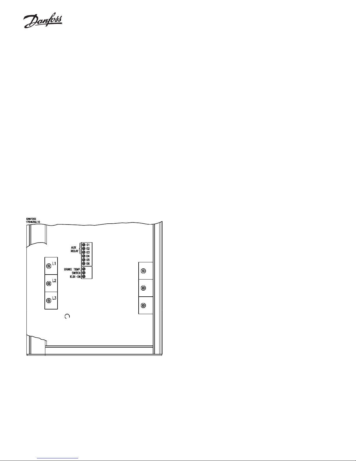
Relay Card Functions – Parameters 700 through 711........................................................................................................................................... 93
Electrical Installation of the Relay Card ..................................................................................................................................................93
Status Messages ...................................................................................................................................................................................................94
Warnings and Alarms ............................................................................................................................................................................................ 96
Calculation of Resulting Reference ...................................................................................................................................................................... 101
Factory Settings .........................................................................................................................................................................................102 - 107
Index ........................................................................................................................................................................................................ 108 - 115
SOFTWARE VERSION NOTICE: These Operating Instructions are used for all VLT 6000
Series Drives with software version 2.X and all prior versions. The software version number
4
can be determined from parameter 624,
Software Version
.
Page 5
General
(
)
The specific installation instructions may vary depending upon the
model of VLT 6000 Series being installed. When this occurs, the model
can be identified by a “VLT T ype 6XXX” number . This number can be
found on the red nameplate on the outside of the left side of the drive
enclosure, or the outside of the right side of a drive with an auxiliary
enclosure. A cross reference from the VLT T ype to the Danfoss
Graham model number can be found on the next page.
The drive must always be installed vertically. To ensure that no injury
or damage occurs, the drive must always be firmly attached to the wall
or the floor before further installation work is carried out.
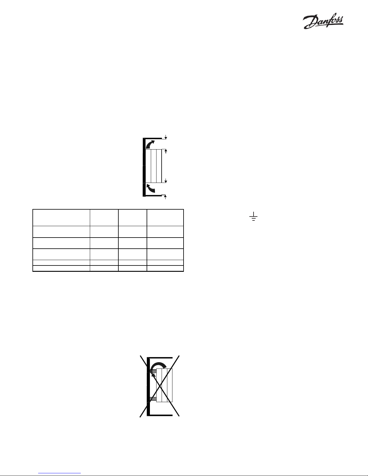
Clearances
The drive is cooled by means of air circulation. For proper cooling, the minimum
distances above and below the unit must be
maintained as shown in the table below. For
units with an auxiliary enclosure mounted with
the drive on a back panel, the required
clearances are measured from the top and
bottom of the drive, not the back panel.
Drive Type
VLT 6002-6005, 200-240V
VLT 6002-6011, 380-460V
VLT 6006-6032, 200-240V
VLT 6016-6062, 380-460V
VLT 6042-6062, 200-240V
VLT 6075-6125, 380-460V
VLT 6150-6275, 380-460V
VLT 6350-6550, 380-460V 16" (400mm) floor mount
Top
Clearance
4" (100mm) 4" (100mm) No
8" (200mm) 8" (200mm) Yes
9" (225mm) 9" (225mm) Yes
300mm) 12" (300mm
12"
Bottom
Clearance
All drives can be mounted with no side clearance. VLT 6350-6550
drives require 25 inches (605 mm) front space for access.
All drives except VLT 6002-6005, 200 to 240 V and VLT 6002-6011,
380 to 460 V must be mounted directly to the wall with no spacers. This
is to ensure that air flow is in contact with the heatsink all the way from
the bottom of the drive. If this is not possible, a metal plate at least as
large as the back of the drive must be firmly mounted to the back of the
drive. See the Cross Reference T able on the next page to convert
model numbers to drive type.
X
X
Must be mounted
flush to wall
Yes
Yes
Sufficient space must be left in front of the drive to provide for door
swing on units with a hinged door. In addition, sufficient room must be
available for installation and service access. On units with an auxiliary
enclosure, the auxiliary enclosure door will have a greater door swing
than the drive. See the dimensional drawings of the auxiliary enclosure
which are included with the drive.
Plenum Mounting
The drive is UL rated for plenum mounting. If the drive is to be mounted
in the plenum, allow sufficient access for servicing. All normal
clearance, temperature and humidity limitations apply.
Grounding Plate
VLT Type 6002-6005, 200 to 240 V and VLT 6002-6001, 380 to 460 V
drives with a NEMA 1 enclosure have a plastic bottom cover with
provision for conduit entry . T o meet UL requirements, the metal
grounding plate must be in place above the plastic bottom cover. It must
be grounded to the chassis, and the conduit grounded to it. If the
grounding plate is not factory installed, it must be installed in the drives
that have a plastic bottom panel to ensure proper grounding of the
conduit to the enclosure. Connect the ground wire from the grounding
plate to the ground tab marked with the ground symbol.
This tab is located near the AC line terminal strip. Mount the bottom
cover on the control unit.
Shielded Wires
Wires to control signals should be shielded to reduce radio frequency
noise interference.
When RFI is a concern, shielded cable should be used between the
drive and the motor.
If unshielded control wires are used, control inputs are subject to signal
disturbances. Such disturbances may affect drive operation. Extreme
noise levels may disturb the microprocessor of the control card.
The shield of the control wires must be grounded at the cable clamp at
the bottom of the drive, but the shield must continue with the cable all the
way up to the control card. The shield is not to be connected to any of
the terminals on the control card. For safety reasons, the insulation
around the shield should only be removed where it is connected to the
cable clamp. The insulation should be left on the shield between the
clamp and the terminals.
All drives except VL T 6002-6005, 200 to 240 V
and VL T 6002-6011, 380 to 460 V must be
mounted directly to a solid wall with no spacers
between the drive and the wall.
Generally speaking, all conductors coming from a shielded control
cable must be as short as possible. Long conductor ends attract noise.
The shield must be connected to the chassis by means of the cable
clamp. Long pigtails on the shield reduce the effectiveness of the shield.
5
Page 6
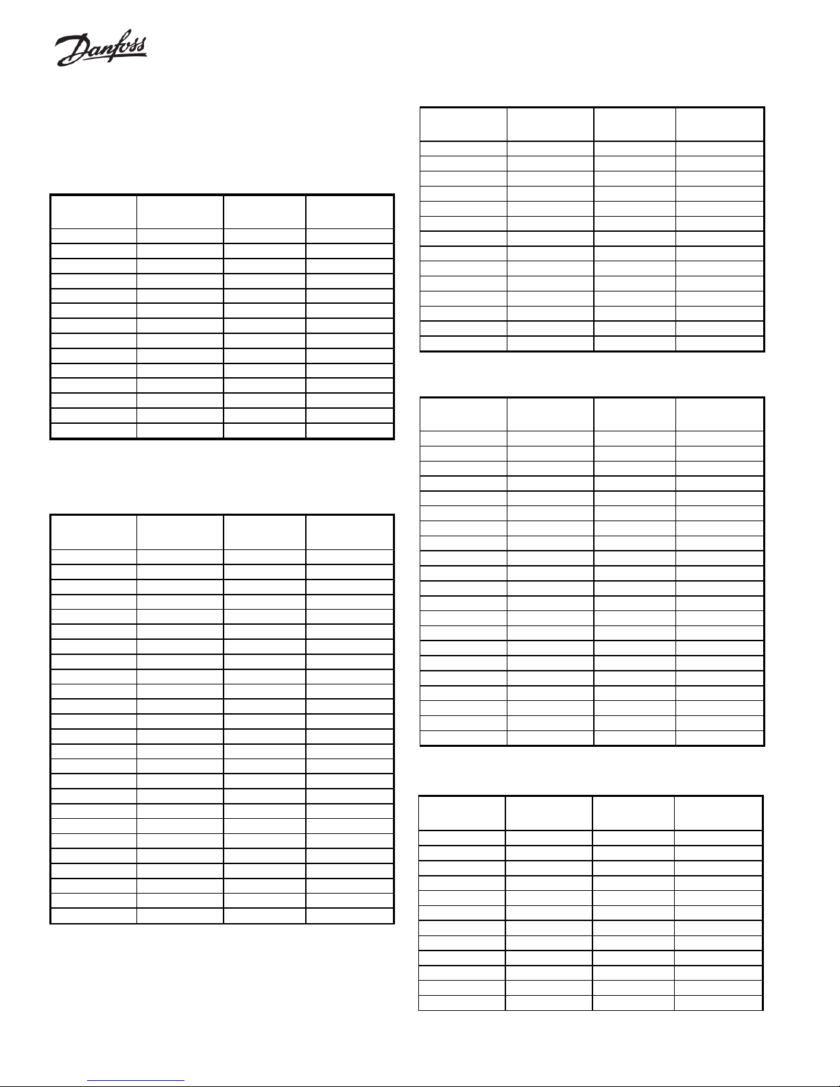
Cross Reference —
Model Number to VLT Type
208 V Input
Model Number VLT Type Max. Nominal
Output HP
VLT6000C4.6 6002 1 4.6
VLT6000C6.6 6002 1½ 6.6
VLT6000C7.5 6003 2 7.5
VLT6000C11
6004
310.6
VLT6000C17 6006 5 16.7
VLT6000C24 6008 7½ 24.2
VLT6000C31 6011 10 30.8
VLT6000C46 6016 15 46.2
VLT6000C59 6022 20 59.4
VLT6000C75 6027 25 74.8
VLT6000C88 6032 30 88
VLT6000C114 6042 40 114
VLT6000C143 6052 50 143
VLT6000C169 6062 60 169
460 V Input
Model Number VLT Type Max. Nominal
Output HP
VLT6000H2.1 6002 1 2.1
VLT6000H3.0 6002 1½ 3.0
VLT6000H3.4 6003 2 3.4
VLT6000H4.8 6004 3 4.8
VLT6000H8.2 6006 5 8.2
VLT6000H11 6008 7½ 11.0
VLT6000H14 6011 10 14
VLT6000H21 6016 15 21
VLT6000H27 6022 20 27
VLT6000H34 6027 25 34
VLT6000H40 6032 30 40
VLT6000H52 6042 40 52
VLT6000H65 6052 50 65
VLT6000H77 6062 60 77
VLT6000H106 6075 75 106
VLT6000H130 6100 100 130
VLT6000H160 6125 125 160
VLT6000H190 6150 150 190
VLT6000H240 6175 200 240
VLT6000H302 6225 250 302
VLT6000H361 6275 300 361
VLT6000H443 6350 350 443
VLT6000H540 6400 450 540
VLT6000H590 6500 500 590
VLT6000H678 6550 600 678
Max. Drive
Output Current
Max. Drive
Output Current
230 V Input
Model Number VLT Type Max. Nominal
Output HP
VLT6000E4.2 6002 1 4.2
VLT6000E6.6 6002 1½ 6.6
VLT6000E7.5 6003 2 7.5
VLT6000R11 6004 3 10.6
VLT6000E17 6006 5 16.7
VLT6000E24 6008 7½ 24.2
VLT6000E31 6011 10 30.8
VLT6000E46 6016 15 46.2
VLT6000E59 6022 20 59.4
VLT6000E75 6027 25 74.8
VLT6000E88 6032 30 88
VLT6000E104 6042 40 104
VLT6000E130 6052 50 130
VLT6000E154 6062 60 154
380 V Input
Model Number VLT Type Max. Nominal
Output kW
VLT6000F3.0 6002 1.1 3.0
VLT6000F4.1 6003 1.5 4.1
VLT6000F5.6 6004 2.2 5.6
VLT6000F7.2 6005 3 7.2
VLT6000F10 6006 4 10
VLT6000F13 6008 5.5 13
VLT6000F16 6011 7.5 16
VLT6000F24 6016 11 24
VLT6000F32 6022 15 32
VLT6000F38 6027 18.5 37.5
VLT6000F44 6032 22 44
VLT6000F61 6042 30 61
VLT6000F73 6052 37 73
VLT6000F90 6062 45 90
VLT6000F106 6075 55 106
VLT6000F147 6100 75 147
VLT6000F177 6125 90 177
VLT6000F212 6150 110 212
VLT6000F260 6175 132 260
VLT6000F315 6225 160 315
VLT6000F368 6275 200 368
575 V Input
Model Number VLT Type Max. Nominal
Output HP
VLT6000J2.7 6016 2 2.7
VLT6000J3.9 6016 3 3.9
VLT6000J6.1 6016 5 6.1
VLT6000J9.0 6016 7½ 9
VLT6000J11 6016 10 11
VLT6000J17 6016 15 17
VLT6000J22 6022 20 22
VLT6000J27 6027 25 27
VLT6000J32 6032 30 32
VLT6000J41 6042 40 41
VLT6000J52 6052 50 52
VLT6000J62 6062 60 62
Max. Drive
Output Current
Max. Drive
Output Current
Max. Drive
Output Current
6
Page 7
Input Fuses
All drives must have input fuses installed in the power supply to the
drive. These fuses may be specified as an option to the drive and
supplied by Danfoss Graham. If specified, they will be installed by
Danfoss Graham in an enclosure external to the drive which may
include other optional features. If not supplied by Danfoss Graham,
they must be supplied by the installer of the drive at the time of
installation.
The required type of fuse for each drive size is shown in the table
below. The fuse rating shown is both the maximum and the recommended fuse rating.
The drives are suitable for use on circuits capable of delivering not
more than 100,000 RMS symmetrical amps, 500 volts maximum (600
volts maximum for 575 volt drives), when used with the recommended
fuses.
208 Volt Input
Maximum Fuse
Model Number VLT Type
VLT6000C4.6 6002 10 KTN-R or JJN
VLT6000C6.6 6003 15 KTN-R or JJN
VLT6000C7.5 6003 20 KTN-R or JJN
VLT6000C11 6004 25 KTN-R or JJN
VLT6000C17 6006 50 KTN-R or JJN
VLT6000C24 6008 50 KTN-R or JJN
VLT6000C31 6011 50 KTN-R or JJN
VLT6000C46 6016 60 KTN-R or JJN
VLT6000C59 6022 80 KTN-R or JJN
VLT6000C75 6027 125 K TN-R or JJN
VLT6000C88 6032 125 K TN-R or JJN
VLT6000C114 6042 150 FWX or FWH
VLT6000C143 6052 200 FWX or FWH
VLT6000C169 6062 250 FWX or FWH
Rating Bussman Type
460 Volt Input
Maximum Fuse
Model Number VLT Type
VLT6000H2.1 6002 6 KTS -R or JJS
VLT6000H3.0 6002 6 KTS -R or JJS
VLT6000H3.4 6003 10 KTS-R or JJS
VLT6000H4.8 6004 10 KTS-R or JJS
VLT6000H8.2 6006 20 KTS-R or JJS
VLT6000H11 6008 25 KTS-R or JJS
VLT6000H14 6011 30 KTS-R or JJS
VLT6000H21 6016 40 KTS-R or JJS
VLT6000H27 6022 40 KTS-R or JJS
VLT6000H34 6027 50 KTS-R or JJS
VLT6000H40 6032 60 KTS-R or JJS
VLT6000H52 6042 80 KTS-R or JJS
VLT6000H65 6052 100 KTS-R or JJS
VLT6000H77 6062 125 KTS-R or JJS
VLT6000H106 6075 150 FWH
VLT6000H130 6100 200 FWH
VLT6000H160 6125 250 FWH
VLT6000H190 6150 300 FWH
VLT6000H240 6175 350 FWH
VLT6000H302 6225 400 FWH
VLT6000H361 6275 500 FWH
VLT6000H443 6350 600 FWH
VLT6000H540 6400 700 FWH
VLT6000H590 6500 800 FWH
VLT6000H678 6550 800 FWH
Rati ng Bussma n Type
575 Volt Input
Model Numbe r VLT Type
VLT6000J2.7 6016 6 KTS-R or similar
VLT6000J3.9 6016 6 KTS-R or similar
VLT6000J6.1 6016 10 KTS-R or similar
VLT6000J9 6016 20 KTS-R or similar
VLT6000J11 6016 25 KTS-R or sim ilar
VLT6000J17 6016 40 KTS-R or sim ilar
VLT6000J22 6022 40 KTS-R or sim ilar
VLT6000J27 6027 50 KTS-R or sim ilar
VLT6000J32 6032 60 KTS-R or sim ilar
VLT6000J41 6042 80 KTS-R or sim ilar
VLT6000J52 6052 100 KTS-R or similar
VLT6000J62 6062 125 KTS-R or similar
Maximum Fuse
Rating Bussman Type
All fuse ratings are in amps
All fuse ratings are in amps
7
Page 8
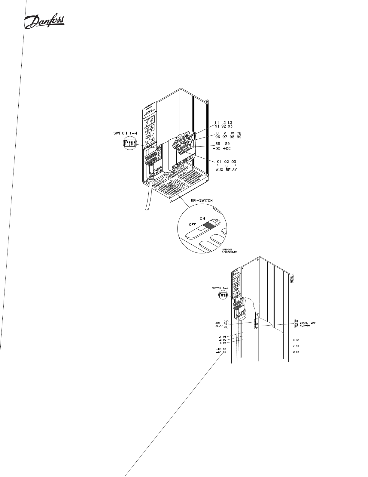
Locations of Conduit Entry, Terminal Blocks
and Switches
NEMA 1
VLT 6002-6032, 200 to 240 V
VLT 6002-6062, 380 to 575 V
VLT 6042-6062, 200 to 240 V, VLT 6075-6125, 380 to 460 V VLT 6150-6275, 380 to 460 V
8
Page 9
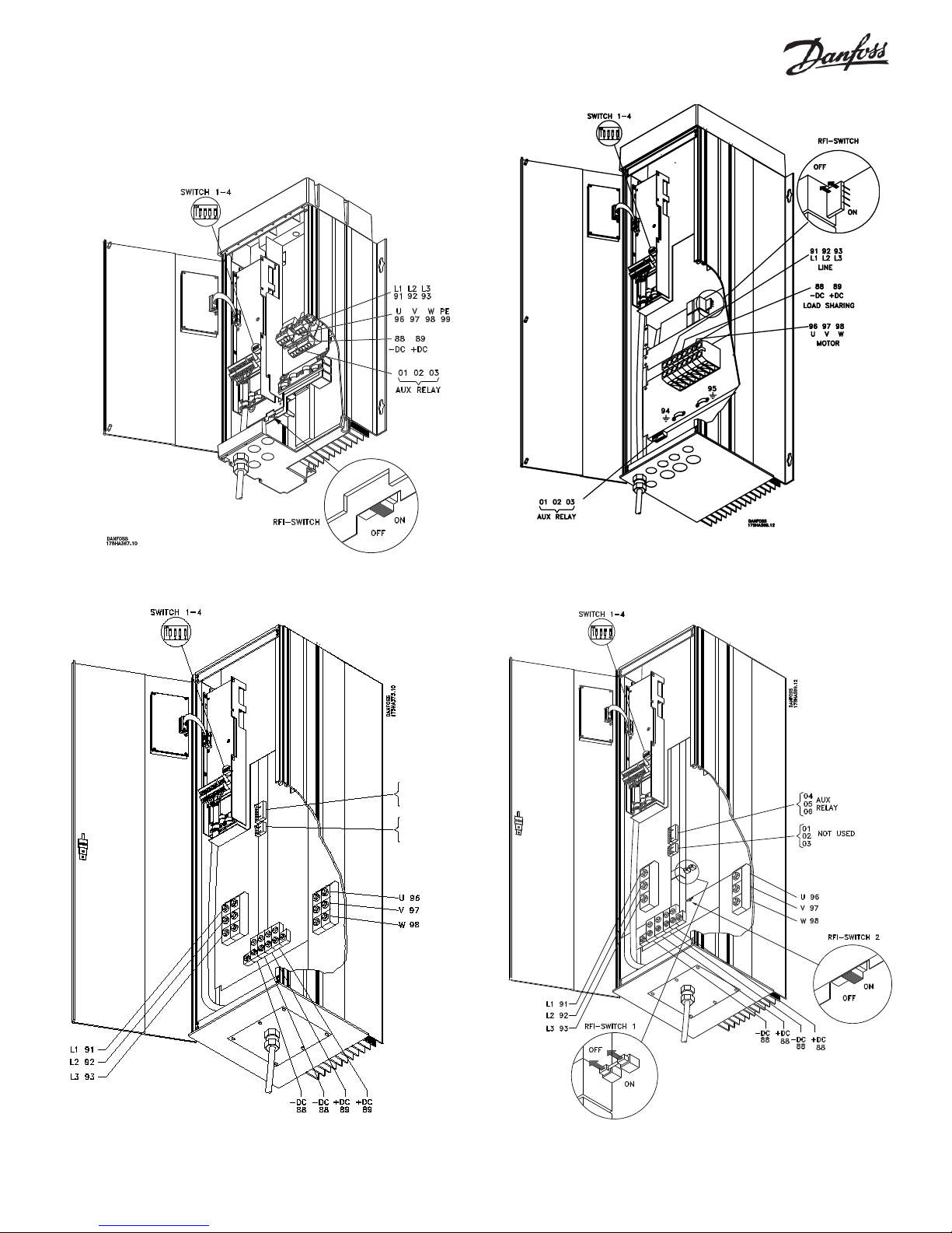
Locations of Conduit Entry, Terminal Blocks
and Switches (continued)
NEMA 12
VLT 6002-6005, 200 to 240 V, VLT 6002-6011, 380 to 460 V VLT 6006-6032, 200 to 240 V ; VLT 6016-6032, 380 to 460 V
VLT 6042-6062, 200 to 240 V ; VLT 6075-6125, 380 to 460 V VLT 6150-6275, 380 to 460 V
9
Page 10
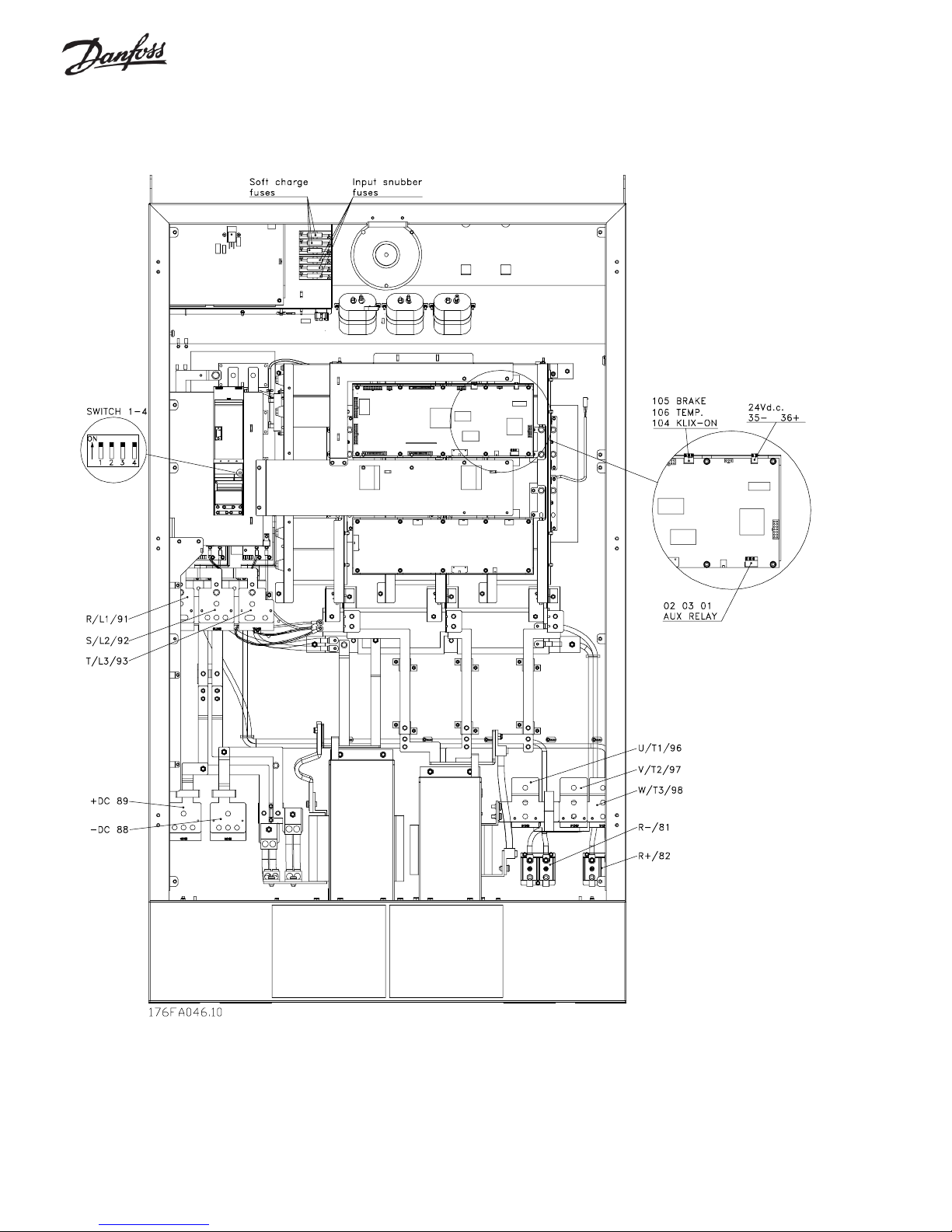
Locations of Conduit Entry, Terminal Blocks
and Switches (continued)
NEMA 1 and NEMA 12
10
VLT 6350-6550, 380 to 460 V
Page 11
Location of Input Power (Mains) and Output
WARNING
!
Power (Motor Terminal Blocks)
Connect input power to the terminals identified as L1, L2 and L3.
Connect the motor leads to the terminals identified as U, V and W.
Connecting input power to motor terminals will
result in drive failure when the power is applied.
NEMA 1 and NEMA 12
VLT 6002-6005, 200-240 V
VLT 6002-6011, 380-460 V
NEMA 1
VLT 6006-6032, 200-240 V
VLT 6016-6062, 380-575 V
NEMA 1
VLT 6042-6062, 200-240 V
VLT 6075-6125, 380-460 V
NEMA 1
VLT 6150-6275, 380-460 V
11
Page 12
Location of Input Power (Mains) and Output
Power (Motor Terminal Blocks), continued
Connect input power to the terminals identified as L1, L2 and L3.
NEMA 12
VLT 6006-6032, 200-240 V
VLT 6016-6062, 380-460 V
NEMA 12
VLT 6042-6062, 200-240 V
VLT 6075-6125, 380-460 V
NEMA 12
VLT 6150-6275, 380-460 V
12
Page 13

Location of Input Power (Mains) and Output
Power (Motor Terminal Blocks), continued
Connect input power to the terminals identified as L1, L2 and L3.
NEMA 1 and NEMA 12, VLT 6350-6550, 380-460 V
without disconnector and mains fuses
NEMA 1 and NEMA 12, VLT 6350-6550, 380-460 V
with disconnector and mains fuses
13
Page 14
Power Connections
o
Make all power connections with 75
C rated copper wiring.
Conduit entry must be from the bottom on all drives. Conduit entries are
provided on smaller drives. For drives with auxiliary enclosures, refer
to the dimensional drawings provided for conduit entry locations.
T o meet UL requirements, install the metal grounding plate in all drives
that have a plastic bottom. Install the grounding plate just above the
plastic bottom. Ground the metal plate to the chassis and ground the
conduit to the metal plate.
The conduit entries provide strain relief for the wires in drives mounted
in NEMA 1 or NEMA 12 enclosures. With chassis mounted drives, the
power and control wires must have strain relief supplied by the installer.
O NOT rely on the terminal blocks to provide strain relief.
D
Input Power Connection
For drives with no auxiliary enclosure, connect input power to drive
terminals L1, L2, and L3, (terminal numbers 91, 92, and 93). If an auxiliary
enclosure is provided, input power connections are made in the auxiliary
enclosure. Refer to the connection diagrams shipped with the drive.
Size wiring to the input current of the drive as shown in the tables
below. Maximum AWG wire size is also provided.
WARNING
!
Connecting input power to motor terminals will
result in drive failure when power is applied.
Motor Wiring Connection
For drives with no auxiliary enclosure, connect the motor to drive
terminals U, V , and W (terminal numbers 96, 97, and 98). T erminal 99
is earth ground. If an auxiliary enclosure is provided, refer to the
connection diagrams shipped with the drive. Ground the shield on the
motor wire, if used, at both the drive and the motor.
DANGER
!
For operator safety, it is important to ground
drive properly.
Grounding
Ground the drive properly. Use a ground wire at least 7 AWG (10mm2).
Connect the ground wire directly to a reliable earth ground. Do not use
the conduit connecting to the drive as a replacement for a ground wire. Do
not ground one drive to another in a “daisy chain” fashion.
Electronic Thermal Protection
The electronic thermal relay is UL approved for single motor thermal
protection as long as the following is complied with:
CAUTION
!
Enclosures for larger drives and auxiliary enclosures are made of metal. To avoid getting
metal chips into electronics, do not drill any
holes after unit has been installed in a vertical
position.
575 VAC Input Current/Wire Gage
208 VAC Input Current/Wire Gage
Drive Input
Current
5.0 10
6.0 10
7.0 10
10.0 10
16.0 10
23.0 6
30.0 6
46.0 6
59.2 2
74.8 2
88.0 0
101.3 1/0
126.6
149.9 4/0 C169
Maximum
AWG
3/0
Model
C4.6
C6.6
C7.5
C11
C17
C24
C31
C46
C59
C75
C88
C114
C143
All current ratings are in amps.
1. Parameter 1 17, Thermal Protection, is set to ETR TRIP .
2. Parameter 105, Motor Current, is set for the full-load nameplate
Drive Input
Current
2.5 6 J2.7
3.0 6 J3.9
6.0 6 J6.1
9.0 6 J9.0
10.0 6 J11
16.7 6 J17
21.6 6 J22
26.6 6 J27
31.5 6 J32
40.3 2 J41
51.2 2 J52
61.0 0 J62
Maximum
AWG
motor current.
Model
460 VAC Input Current/Wire Gage
Drive Input
Current
2.5 10 H2.1
2.5 10 H3.0
3.4 10 H3.4
4.8 10 H4.8
8.3 10 H8.2
10.6 10 H11
27.6 6 H27
103 1/0 H106
145 2/0 H130
174 3/0 H160
206 2x1/0 H190
256 2x1/0 H240
317 2x3/0 H302
366 2x4/0 H361
443 3x1/0 H443
540 3x3/0 H540
590 3x3/0 H590
678 3x4/0 H678
Maximum
AWG
14 10 H14
21 6 H21
34 6 H34
41 6 H40
53 2 H52
64 2 H65
77 2 H77
Model
14
Page 15
y
y
Terminal Tightening Torque
Tighten terminals connecting the drive input power, output to the motor(s)
and ground to the values shown in the tables below. Drives with 200 to
240 volts of 88 amps and less, and drives with 380 to 575 volts of 90 amps
and less, have removable terminal blocks with screws. Larger drives have
fixed bolts. (See the drive nameplate for maximum drive output current.)
200 to 240 VAC Terminal Tightening Torque
NOTE
Tighten terminals of 575 volt drives of 32 amps
and below to 17 in-lbs (1.8 Nm), and above 32
amps to 28 in-lbs (3.0 Nm).
380 to 460 VAC Terminal Tightening Torque
Max. Drive
Output Current
6.6 5 (0.6)
7.5 5 (0.6)
10.6 5 (0.6)
16.7 5 (0.6)
24.2 17 (1.8)
30.8 17 (1.8)
46.2 28 (3.0)
59.4 28 (3.0)
74.8 28 (3.0)
88 35 (4.0)
114 100 (11.3)
143 100 (11.3)
169 100 (11.3)
Torque
in-lbs (Nm )
Max. Drive
Output Current
All current ratings are in amps.
200 to 240 VAC Auxiliary Control Panel Tightening Torques
Max. Drive
Output Current
to 6.6 15 (1.7) 15 (1.7) 22 (2.5) 7 (0.8) 20 (2.3) 35 (4.0) 45 (5.1)
7.5 15 (1.7) 15 (1.7) 22 (2.5) 7 (0.8) 25 (2.8) 35 (4.0) 45 (5.1)
10.6 15 (1.7) 15 (1.7) 22 (2.5) 7 (0.8) 25 (2.8) 35 (4.0) 45 (5.1)
16.7 15 (1.7) 15 (1.7) 22 (2.5) 7 (0.8) 25 (2.8) 35 (4.0) 45 (5.1)
24.2 15 (1.7) 50 (5.7) 22 (2.5) 7 (0.8) 45 (5.1) 45 (5.1) 45 (5.1)
30.8 15 (1.7) 50 (5.7) 22 (2.5) 7 (0.8) 120 (13.6) 45 (5.1) 45 (5.1)
46 75 (8.5) 50 (5.7) 44 (5.0) 18 (2.0) 120 (13.6) 120 (13.6) 45 (5.1)
61.2 75 (8.5) 275 (31.1) 44 (5.0) 18 (2.0) 120 (13.6) 275 (31.1) 50 (5.6)
74.8 120 (13.6) 275 (31.1) 44 (5.0) 18 (2.0) 120 (13.6) 275 (31.1) 50 (5.6)
88 120 (13.6) 275 (31.1) 44 (5.0) 70 (8.0) 120 (13.6) 275 (31.1) 50 (5.6)
115 120 (13.6) 275 (31.1) 44 (5.0) 375 (42.4) 275 (31.1) 150 (16.9) 50 (5.6)
143 250 (28.3) 275 (31.1) 50 (5.6) 375 (42.4) 275 (31.1) 150 (16.9) 120 (13.6)
169 275 (31.4) 275 (31.1) 50 (5.6) 375 (42.4) 275 (31.1) 150 (16.9) 150 (16.9)
Overload
Rela
Power Terminal
Blocks
Circ uit
Breaker
Disconnect or
Transfer Switch
Torque
in-lbs (Nm)
to 10 5 (0.6) 147 100 (11.3)
16 5 (0.6) 177 100 (11.3)
24 17 (1.8) 212 100 (11.3)
32 17 (1.8) 260 100 (11.3)
37.5 17 (1.8) 315 100 (11.3)
44 28 (3.0) 368 100 (11.3)
61 28 (3.0) 487 372 (42.0)
73 28 (3.0) 594 372 (42.0)
90 28 (3.0) 649 372 (42.0)
106 100 (11.3) 746 372 (42.0)
Main or
pass Fuse
B
Block
Drive Fuse
Block
Max. Drive
Output Current
Ground
Term inal
Torque
in-lbs (Nm)
380 to 575 VAC Auxiliary Control Panel Tightening Torques
Max. Drive
Output Current
10 15 (1.7) 15 (1.7) 22 (2.5) 7 (0.8) 20 (2.3) 25 (2.8) 45 (5.1)
16 15 (1.7) 15 (1.7) 22 (2.5) 7 (0.8) 25 (2.8) 25 (2.8) 45 (5.1)
24 75 (8.5) 15 (1.7) 22 (2.5) 7 (0.8) 25 (2.8) 45 (5.1) 45 (5.1)
32 75 (8.5) 35 (4.0) 22 (2.5) 7 (0.8) 45 (5.1) 45 (5.1) 45 (5.1)
37.5 75 (8.5) 35 (4.0) 22 (2.5) 18 (2.0) 45 (5.1) 45 (5.1) 45 (5.1)
44 75 (8.5) 50 (5.6) 44 (5.0) 18 (2.0) 45 (5.1) 120 (13.6) 45 (5.1)
61 75 (8.5) 110 (12.5) 44 (5.0) 18 (2.0) 120 (13.6) 120 (13.6) 50 (5.6)
73 75 (8.5) 110 (12.5) 44 (5.0) 55 (6.2) 120 (13.6) 275 (31.1) 50 (5.6)
90 75 (8.5) 110 (12.5) 44 (5.0) 70 (8.0) 120 (13.6) 275 (31.1) 50 (5.6)
106 120 (13.6) 110 (12.5) 50 (5.6) 375 (42.4) 275 (31.1) 150 (16.9) 50 (5.6)
147 250 (28.3) 275 (31.1) 50 (5.6) 375 (42.4) 275 (31.1) 150 (16.9) 120 (13.6)
177 275 (31.1) 275 (31.1) 50 (5.6) 375 (42.4) 275 (31.1) 150 (16.9) 150 (16.9)
212 275 (31.1) 275 (31.1) 50 (5.6) 375 (42.4) 450 (50.8) 275 (31. 1) 150 (16.9)
260 275 (31.1) 275 (31.1) 375 (42.4) 500 (56.5) 450 (50.8) 275 (31.1) 150 (16.9)
315 375 (42.4) 375 (42.4) 375 (42.4) 500 (56.5) 450 (50.8) 275 (31.1) 150 (16.9)
368 375 (42.4) 375 (42.4) 375 (42.4) 375 (42.4) 375 (42.4) 275 (31.1) 150 (16.9)
All current ratings are in amps. All torques are in in-lbs (Nm). All TB1 connections must be torqued to 8 in-lbs (0.9 Nm).
Overload
Relay
Power Terminal
Blocks
Circuit
Breaker
Disc onnect or
Transfer Switch
Main or
Bypass Fuse
Block
Drive Fuse
Block
Ground
Terminal
15
Page 16
Multiple Motors
The VLT 6000 can control several motors at once, all changing speed
together. The sum of the nameplate currents of all the motors must not
exceed the current rating of the drive.
WARNING
!
When multiple motors are used, VLT 6000 electronic thermal relay cannot be used to provide
individual motor protection. A separate motor overload must be supplied for each motor.
If the multiple motors are of significantly different sizes, starting problems
may occur. This is because the higher electrical resistance of smaller
motors will require more start voltage than larger motors.
CAUTION
!
Automatic Motor Adaptation and Automatic
Energy Optimization cannot be used for multiple motor installations.
External DC Bus Connection
T erminals 88 and 89 access the DC bus of the drive. They can provide
DC backup power for the drive or to connect to a 12-pulse input
rectifier.
DANGER
!
Terminals 88 and 89 will be at approximately
150% of line voltage and remain at high voltage for up to 14 minutes after power has been
removed from the drive.
WARNING
!
Do not connect anything to terminals 88 and 89
without first consulting with Danfoss Graham.
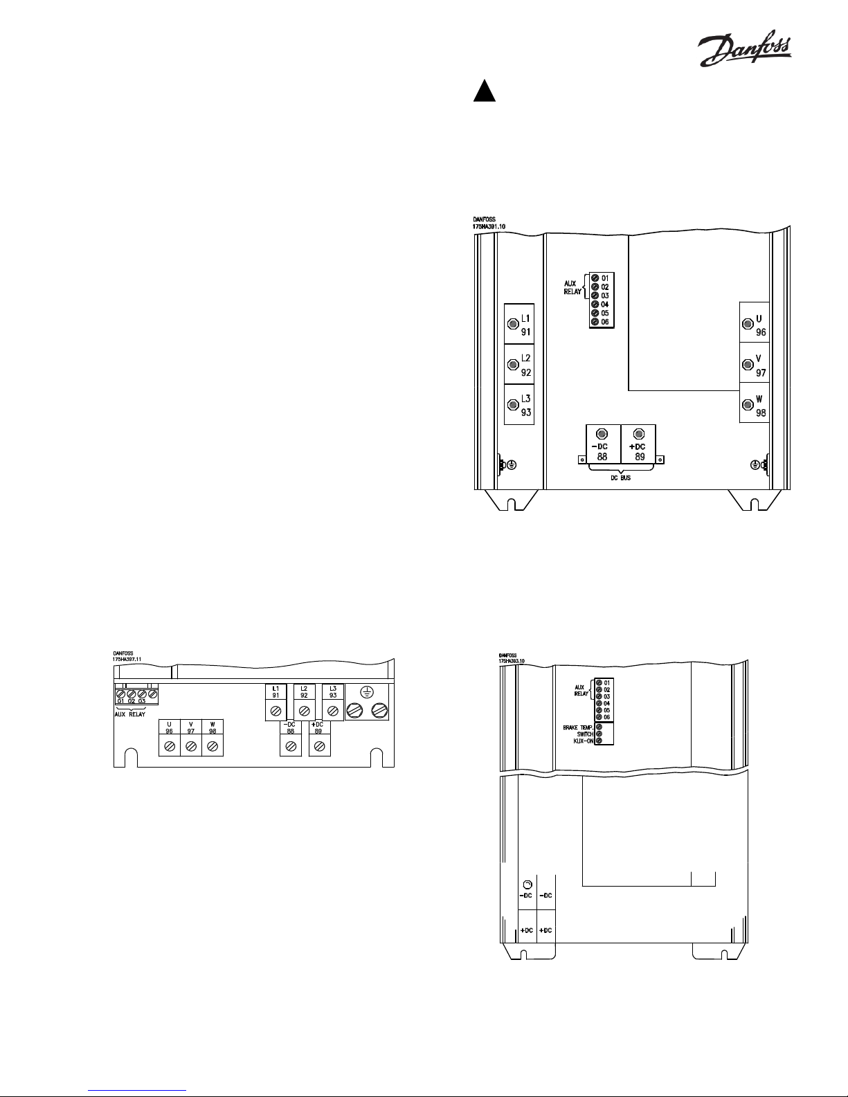
High Voltage Form C Relay
The connections for the high-voltage relay are terminals 01, 02, 03.
The high-voltage relay is programmed in parameter 323, Relay
Output 1.
1+3 normally closed, 1+2 normally open
Max. 240 VAC, 2 Amp
Min. 24 VDC, 10 mA or
24 VAC, 100 mA
Max. wire gage: 10 AWG (4 mm2)
T erminal Torque: 5 in-lbs ( 0.5 - 0.6 Nm)
16
Electronic Control T erminals
Page 17
Control Connections
All terminals for the low voltage control wires are located under the
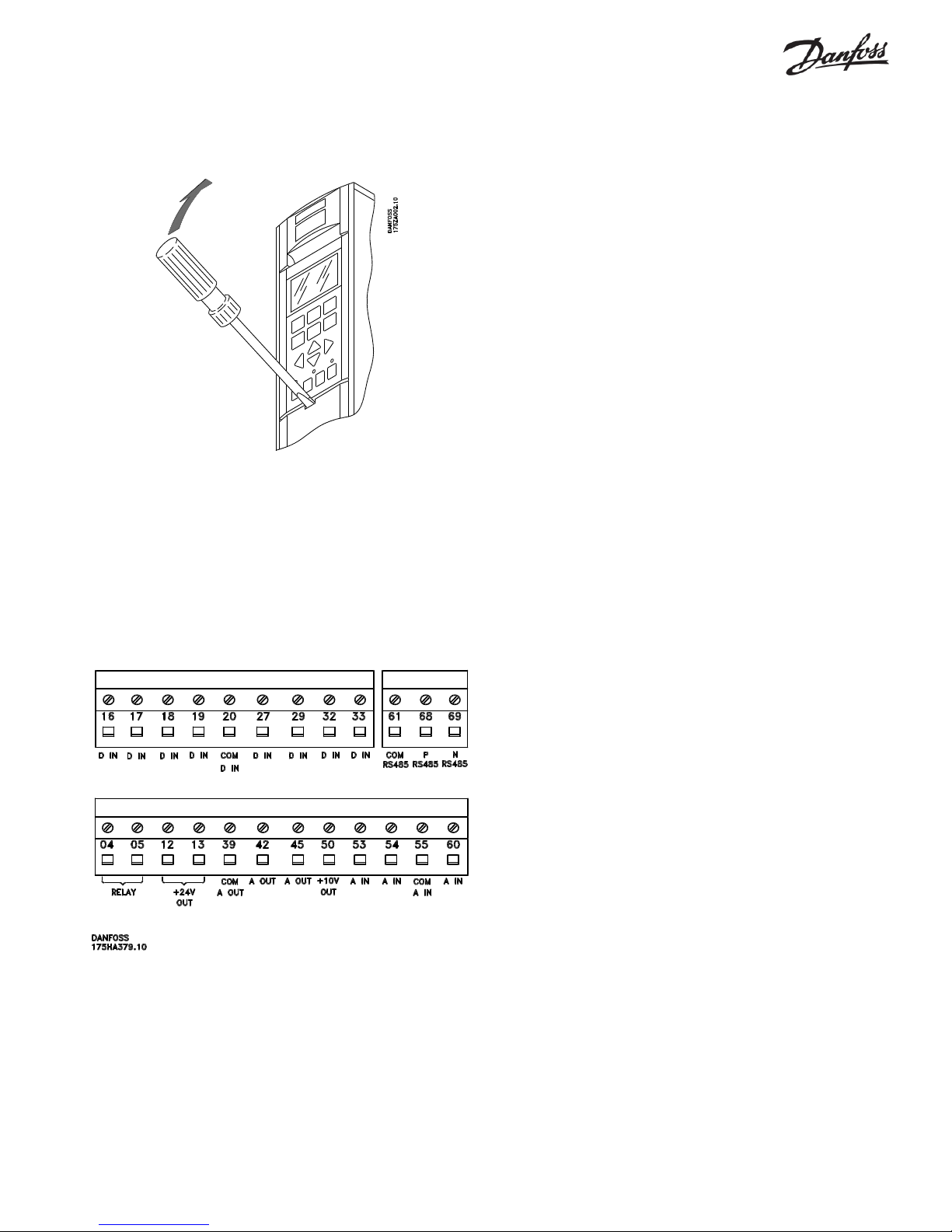
protective cover below the keypad. Remove the cover with a
screwdriver or other pointed object as shown below.
The following is a description of the functions of the control terminals.
Many of these terminals have multiple functions determined by
parameter settings.
No. Function
01, 02, 03 Form C relay output. Maximum 240 V AC, 2 A.
Minimum 24 VDC, 10 mA or 24 VAC, 100 mA.
(Location of Form C relay output varies with unit
type. See connection diagram with unit for
location.)
04, 05 30 VAC, 42.5 VDC, 1 A relay output can be used
for indicating status and warnings.
12, 13 Voltage supply to digital inputs and external
transducers. For the 24 VDC to be used for digital
inputs, switch 4 on the control card must be closed,
position “on.” The maximum output current is 200 mA.
16 - 33 Digital inputs. R = 2 kohm. <5 V = logical “0”,
>10 V = logical “1”. See parameters 300 through
307, Digital Inputs.
Electrical Installation, Control Terminals
T orque the control terminals to 5 in-lbs (0.5-0.6 N-m)
The diagram below shows the location of the control terminals. The
programming section of the manual covers the programmable terminals
in greater depth.
20 Common for digital inputs.
39 Common for analog and digital outputs.
42, 45 Analog and digital outputs for indicating frequency,
reference, current and torque. The analog signal
is 0 to 20 mA, or 4 to 20 mA at a maximum of
500€Ω. The digital signal is 24 VDC at a minimum
of 600 Ω . See parameters 319-322, Analog/
digital Outputs.
50 10 VDC, 17 mA maximum analog supply voltage
to potentiometer and thermistor.
53, 54 0 to 10 VDC voltage input, R = 10 kΩ.
55 Common for analog inputs. This common is
isolated from the common of all other power
supplies. If, for example, the drive’s 24 VDC
power supply is used to power an external
transducer which provides an analog input signal,
terminal 55 must be wired to terminal 39.
60 0 to 20 mA or 4 to 20 mA, analog current input, R
= 188 Ω . See parameters 314 through 316.
61 Shield for serial communication.
68, 69 RS-485 interface and serial communication. When
the drive is connected to an RS-485 serial
communication bus, DIP switch settings on the
control card may have to be reset. See Dip
Switches 1 through 4 in this manual.
17
Page 18
Typical Control Connections
Shown below are typical interfaces between the VLT 6000 and other
components in an HVAC system. The terminal numbers and the
functions of the terminals are identical on all VLT 6000s. An optional
relay card, not shown, can provide four additional Form C output
relays. The RS-485 connections allow direct communication through
Typical* VLT 6000 Wiring
the drive’s built-in serial communication protocols: Johnson Controls
®
Metasys
N2, Siemens System 600 FLN®, or VLT Software Dialog®.
LonWorks® and Profibus® are available through option cards that fit into
the relay output card location.
3 Phase
Power
Input
External
DC Bus
Connection
+10 V DC
0 - 10 V DC
Ref. Input*
0 - 10 V DC
Ref. Input*
4 - 20 mA
Ref. Input*
Reset*
Lockout*
Run/Stop*
Reverse*
Interlock*
Preset Speed*
91 (L1)
92 (L2)
93 (L3)
99 (PE)
88 (-)
89 (+)
50 (+10 V OUT)
53 (A IN)
54 (A IN)
55 (COM A IN)
60 (A IN)
12 (+24 V OUT)
13 (+24 V OUT)
16 (D IN)
17 (D IN)
18 (D IN)
19 (D IN)
20 (COM D IN)
27 (D IN)
29 (D IN)
SW4
Switch Mode
Power Supply
10 V DC
17 mA
+-
RS-485
Interface
+-
5 V
SW2 SW3
24 V DC
200 mA
(U) 96
(V) 97
(W) 98
(PE) 95
(AUX RELAY) 01
( AUX RELAY) 02
(AUX RELAY) 03
(RELAY) 04
(RELAY) 05
(COM A OUT) 39
(A OUT) 42
0 V
(A OUT) 45
(P RS-485) 68
(N RS-485) 69
(COM RS-485) 61
Motor
Fault Indication*
240 V AC, 2 A
Run Indication*
30 V AC, 1 A
Output Current Indication*
4 - 20 mA
Output Speed Indication*
4 - 20 mA
+
RS-485
-
Setup Select*
Setup Select*
32 (D IN)
33 (D IN)
* The operation of all control inputs and outputs is programmable.
* Typical terminal functions are shown.
18
Page 19
CAUTION
!
Incoming power, motor wiring and control wiring should be run in three separate conduits or
raceways.
Electrical Installation, Control Wiring
Torque: 5 - 6 in-lbs
Screw size: M3
Shield control wires, when necessary, to reduce interference from
electrical noise by means of a cable clamp at both ends to the metal
enclosure of the unit. Connect the shield to earth ground. Very long
control wires may create 60 Hz interference. This problem can be
solved by connecting one end of the shield to earth with a 0.1 µF
capacitor, keeping the leads as short as possible. If this doesn’t solve
the problem, disconnect the shield’s connection to earth ground at the
end opposite to the drive.
DIP Switches 1 through 4
DIP switches are located on the control card.
They are used for serial communication and the common of digital
inputs 16 through 33. The switch positions shown are the factory
settings.
Switch 1 is not used.
Switches 2 and 3 are used for terminating serial communication. On the
first and last drive in a multiple device network, or on the only drive of a
single drive network, switches 2 and 3 must be ON (the default setting).
On all other drives in a multiple device network, set switches 2 and 3 to
OFF.
Switch 4 separates the common for the internal 24 VDC supply from the
common of the external 24 VDC supply. Normally this switch is ON and
the power supply is present at terminals 12 and 13. Set Switch 4 to the
OFF position when an external 24 VDC supply is used.
Ground Leakage Current
It is normal for there to be some leakage current from the drive to earth
ground. Paths of current leakage are shown on the drawing below.
The leakage current will exceed 3.5 mA.
Paths of Normal Current Leakage to Ground
19
Page 20
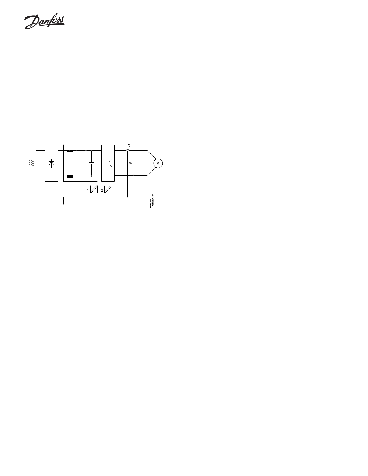
Galvanic Isolation
Galvanic isolation offers protection from electric shock. All control
terminals of all VLT 6000 drives, and terminals 1 through 3 of the relay
output, offer galvanic isolation as long as the RFI switch (if provided) is
in the ON position. The galvanic isolation in the VLT 6000 conforms to
the European standard EN 50178. (See figure below.)
The components that make up the galvanic isolation are:
1. Power supply, including signal isolation.
2. Gate drive for the IGBT s, the trigger transformers and optocouplers.
3. The output current Hall effect transducers.
Galvanic Isolation
Electrical Noise
In general, electrical noise can be divided into two forms: wire-borne
electromagnetic interference (EMI), and radiating radio frequency
interference (RFI).
Using shielded motor cables reduces RFI but increases EMI. This is
because shielded wires have a greater capacitance than unshielded
wires. Unshielded input power connections to the drive generate more
noise in the radio frequency range on the AC line. The shield reduces
the radiated noise, but increases the low-frequency electromagnetic
noise on the AC line. But, since the noise current is taken back to the
unit through the shield, only a small electromagnetic field is generated
from shielded motor wires.
With an EMI filter, the noise level on the AC line will be reduced to
about the same level for shielded and unshielded wires alike.
Connect the motor wiring shield, if used, in the enclosure of the drive as
well as at the motor. Use shield brackets to avoid “pigtail” shield ends.
Even short “pigtails” increase the shield’s impedance at higher
frequencies, which reduces the shield’s effect and increases the noise
produced.
It is generally easier and less complicated to use unshielded motor
wires than shielded cables. If unshielded wires are used, the RFI will
be greater. But, since the strength of the radiated signal decreases with
distance from the signal source, radiated noise is generally not a
problem.
T o reduce the noise level from the total system (drive + installation)
make the motor wiring as short as possible.
Provide separate conduits, or raceways, for power, motor and control
wiring to provide the greatest immunity from distortion.
20
Page 21
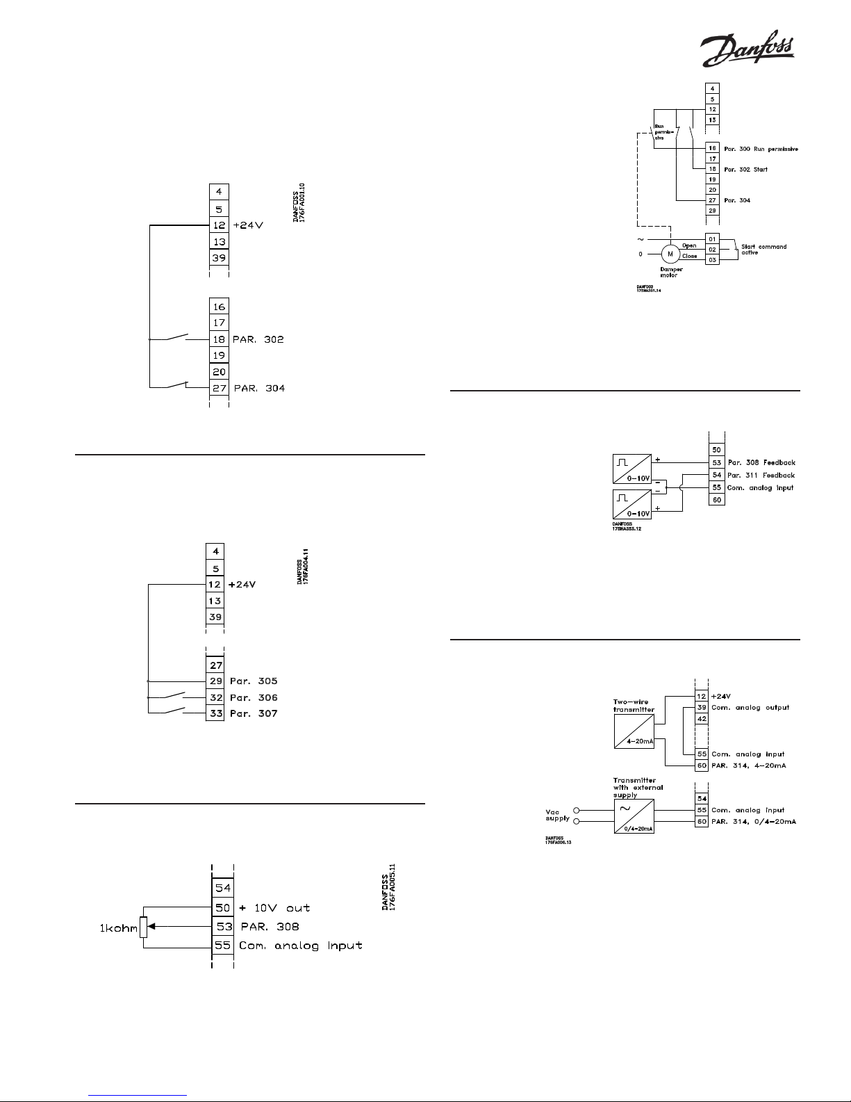
Application Control Connection Examples
Two-wire Start/Stop
In Auto mode, closing the contact to terminal 18 will make the drive run.
In any mode, opening the safety interlock contact to terminal 27 will stop
the drive.
Set Parameter 302 to Start.
Set Parameter 304 to External Fault.
Digital Speed Up/down
Closing the switch to terminal 32 will make the drive accelerate. Closing
the switch to terminal 33 will make the drive decelerate.
Run Permissive
After receiving a run command,
the drive will apply power to the
damper motor and wait until it
receives “permission” via the
switch that is connected to
terminal 16.
Set Parameter 300 to Run Permissive.
Set Parameter 302 to Start.
Set Parameter 304 to External Fault.
Set Parameter 323 to Start Signal Applied.
Two Feedback Signals
The drive processes two
independent feedback
signals during closed loop
operation. It can respond to
the sum, difference,
average, minimum or
maximum of these signals.
Set Parameter 306 to Speed up.
Set Parameter 307 to Speed down.
Set Parameter 305 to Freeze reference.
Potentiometer Reference
A manual potentiometer is used as a input reference for the drive.
Set Parameter 308, T erminal 53, Analog Input V oltage, to Reference.
Set Parameter 309, T erminal 53, Min. Scaling, to 0 V.
Set Parameter 310, T erminal 53, Max. Scaling, to 10 V.
Set Parameter 308 to FEEDBACK.
Set Parameter 311 to FEEDBACK
Set Parameter 417 for the desired operation.
Transmitter Connection
The drive’s internal 24
VDC power supply is
used to power an
external 4 to 20 mA
transducer.
Set Parameter 314, T erminal 60, Analog Input Curent, to
correspond to the purpose of the 4 to 20 mA signal.
Set Parameter 315, T erminal 60, Min. Scaling, to 4 mA
Set Parameter 316, T erminal 60, Max. Scaling, to 20 mA.
Because the commons of the +24 VDC power supply and the input
reference follower have separate circuit commons, it is necessary to
connect a jumper between terminals 39 and 55.
21
Page 22
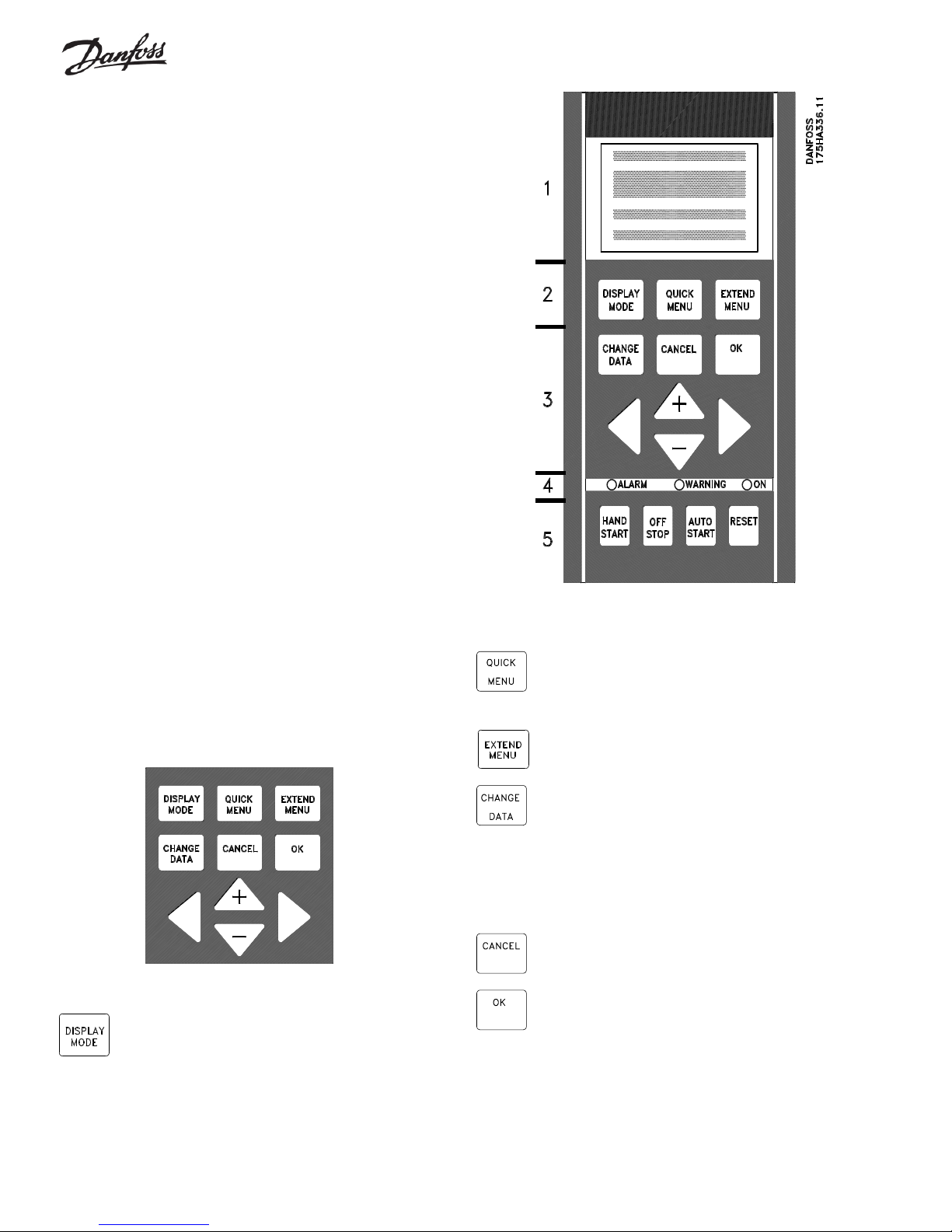
Control Panel
The Local Control Panel (LCP), normally mounted on the front of the
drive, is a complete interface for programming and operating the drive.
The control panel can be removed from the drive and installed up to 10
feet (3 meters) from the drive by using a remote mounting kit.
The control panel has five functions:
1. Display
2. Keys for changing the display
3. Keys for changing programming parameters
4. Keys for controlling drive operation
5. Indicator lamps
The LCP uses a four-line, alpha-numeric, back-lit, LCD display. The
display can show four operating data values and three operating
condition values continuously. During programming, all the information
required for quick, effective parameter setup of the drive will be
displayed. As a supplement to the display, there are three indicator
lamps for power on (ON), warning (WARNING) and alarm (ALARM).
All drive parameters can be changed from the control panel, unless this
ability has been locked out by setting parameter 016, Lock for Data
Change, to Locked, or by a digital input to terminals 16 through 33. See
the related parameters for more information.
Keys for Parameter Changes
The keys are divided into groups by function. The keys between the
display and indicator lamps are used for parameter setup, selecting the
display indication during normal operation and controlling the drive
speed during local speed control operation. The keys below the
indicator lamps are used for Start/Stop control and selection of the
operating site.
The DISPLAY MODE key is used to select the mode of
the display or to return to the Display Mode from either
the Quick Menu or the Extend Menu mode.
The QUICK MENU key gives access to the parameters
available for the Quick Menu setup. Parameters in this
menu are the 12 most important setup parameters for
the drive.
The EXTEND MENU key gives access to all parameters.
The CHANGE DATA key is used for changing the value
of a parameter selected either in the Extend Menu or
the Quick Menu mode. The desired parameter is first
selected. Then the CHANGE DAT A key is pressed to
enable the editing of the parameter. The underline in the
display will move under the parameter’s value to show
that it is being edited.
The CANCEL key is used if a change of the selected
parameter is not to be carried out.
The OK key is used for confirming a change of the
parameter selected.
22
Page 23
The + and - keys are used to scroll through parameters
and to change the value of a chosen parameter. These
keys are also used to change the local reference. In
Display Mode, these keys are used to switch between
readouts.
The L and M keys are used to select a parameter
group and also to move the cursor to the desired digit
when changing numerical values.
Indicator Lamps
At the bottom of the control panel is a red alarm LED, a yellow warning
LED, and a green power on LED.
red yellow green
The OFF/STOP key is used for stopping the connected
motor in either the Hand or Auto mode. Enable or
Disable via parameter 013. If this stop function is
activated, the second line in the LCD display will flash.
AUTO ST ART is used if the drive is to be started via the
control terminals and/or serial communication. When a
remote start signal is active, the drive will start if the
AUTO ST ART key has been pressed.
DANGER
!
A start signal via digital inputs may cause drive
to start at any time. Remove power to drive before working on output wiring, motor or any
driven equipment.
If certain threshold values are exceeded, the alarm and/or warning
lamps will flash and text describing the alarm or warning condition will
be displayed.
Local Control
Below the indicator lamps are keys which are used to determine the
point of control. Each of these keys can be individually enabled or
disabled using parameter 012 through 015. The Hand Start and Auto
Start keys will also be disabled if any of the control terminals are
programmed for either Remote Hand or Remote Auto.
The HAND STAR T key is used if the drive is to be
started from the control panel. Pressing HAND STAR T
will give a start command to the drive.
WARNING
!
If a minimum speed is set in parameter 201,
Output Frequency Low Limit
and ramp up to this frequency when HAND
START is pressed. If drive is already running in
Auto Mode when the HAND START key is
pressed, it will switch to run in Hand Mode at
same speed.
, motor will start
The RESET key is used for manually resetting the drive
after a fault trip (alarm). In this case, the top line of the
display will show TRIP (RESET). If the top line of the
display shows TRIP (AUTO START), the drive will
automatically restart. If the top line of the display shows
TRIPLOCK (DISC. MAINS), input power to the drive
must be removed before the trip can be reset.
Display Mode
Information is displayed on the LCD by selecting one of three programmable display modes. Pressing the Display Mode key toggles among
the displays. When in Mode II, pressing and holding down the Display
Mode key accesses an additional mode used to identify the data units
the display is showing. (See Navigation Between Display Modes.)
In normal operation, any four meters can be shown continuously on the
first and second lines of the display. Parameters 008, 009 and 010
select the three readouts displayed on the top line. Parameter 007,
Large Display Readout, selects the meter displayed on line 2. In
Display Mode, the + and - keys choose any meter on the LCD.
A list on the next page gives the operating data that can be shown on
the three meter readouts for line 1 and the large display (line 2).
The right side of line 2 shows the active setup number and an arrow
indicateing the direction of motor rotation. Clockwise indicates forward
and counterclockwise indicates reverse. The arrow body disappears if
a stop command is given or if the output frequency falls below 0.01 Hz.
Warnings and alarms (fault trips) will also be displayed. For an alarm,
“ALARM” and the alarm number is shown in line 2 with an explanation
in line 3 or in lines 3 and 4. For a warning, “WARN.” and the warning
number is shown in line 2 and an explanation in 3 and/or 4. Both
alarms and warnings cause the display to flash.
The line 4 automatically displays the operating status of the drive.
23
Page 24
The table below gives the operating data options for the first and
second lines of the display .
Data Item: Unit:
Resulting reference, % %
Resulting reference unit chosen in par. 415
Frequency Hz
% of maximum output frequency %
Motor current A
Power kW
Power HP
Output energy kW h
Hours run hours
User defined readout unit chosen in par. 006
Setpoint 1 unit chosen in par. 415
Setpoint 2 unit chosen in par. 415
Feedback 1 unit chosen in par. 415
Feedback 2 unit chosen in par. 415
Feedback unit chosen in par. 415
Motor voltage V
DC link voltage V
Thermal load on motor %
Thermal load on VLT %
Input status, digital input binary code
Input status, analog terminal 53 V
Input status, analog terminal 54 V
Input status, analog terminal 60 mA
Pulse reference Hz
External reference %
Heat sink temperature
o
C
Line 4 is the status line and the information is automatically generated
for display by the drive in response to its operation. It shows that the
drive is in auto mode, with remote reference, and that the motor is
running. Some possible displays of the status line are shown below.
80.0% 5.08A
2.15kW
40.0Hz
SETUP
1
AUTO REMOTE RUN
HAND
OFF
LOCAL
STOP
RAMPING
JOGGING
.
.
.
.
STAND BY
The left part of the status line indicates where the drive Run/Stop
command is from, and whether it is on or off. AUTO means that Run/
Stop control is via the control terminals and/or serial interface; HAND
indicates that the drive started locally by the Hand Start key . OFF
means that the drive ignores all control commands and the motor will
not run.
The center part of the status line indicates the reference source that is
active. REMOTE means that the reference is from the control terminals.
LOCAL indicates that the reference is determined by the + and - keys
on the control panel.
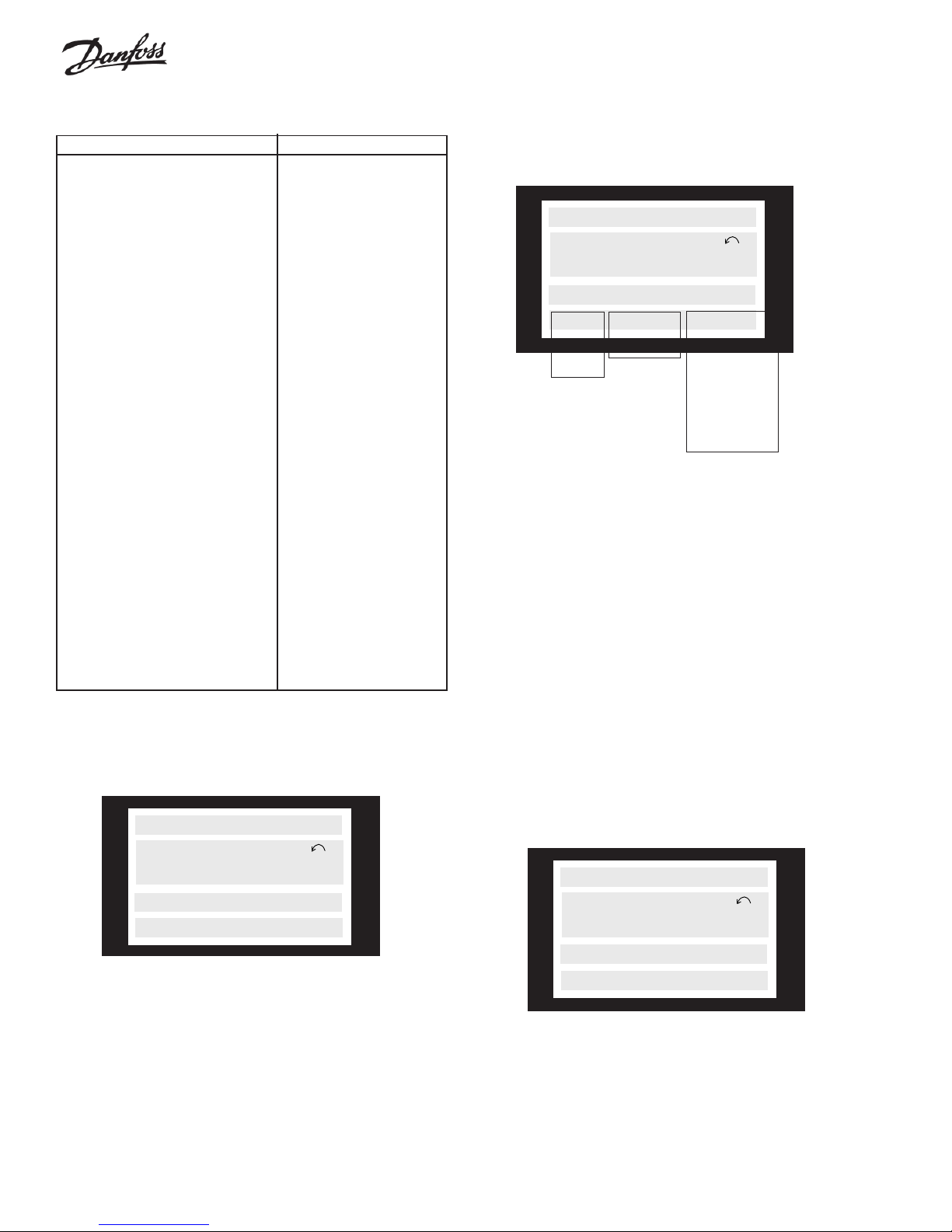
Display Mode I:
Below is an example of Display Mode I, in which the drive is running in
setup 1, in Auto mode, with remote reference, at an output frequency of
40 Hz.
FREQUENCY
SETUP
40.0Hz
1
AUTO REMOTE RUN
The text in line 1, FREQUENCY , describes the meter shown in line 2.
Line 2 shows the current output frequency (40.0Hz), direction of
rotation (reverse), and active setup (1).
The right part of the status line indicates the drive’s operational status.
Display Mode II:
This display mode makes it possible to have three meters displayed at
the same time on line 1. The meters displayed are selected through
parameters 008, 009 and 010.
100% 7.8A 5.9kW
SETUP
50.0Hz
1
AUTO REMOTE RUN
24
Page 25
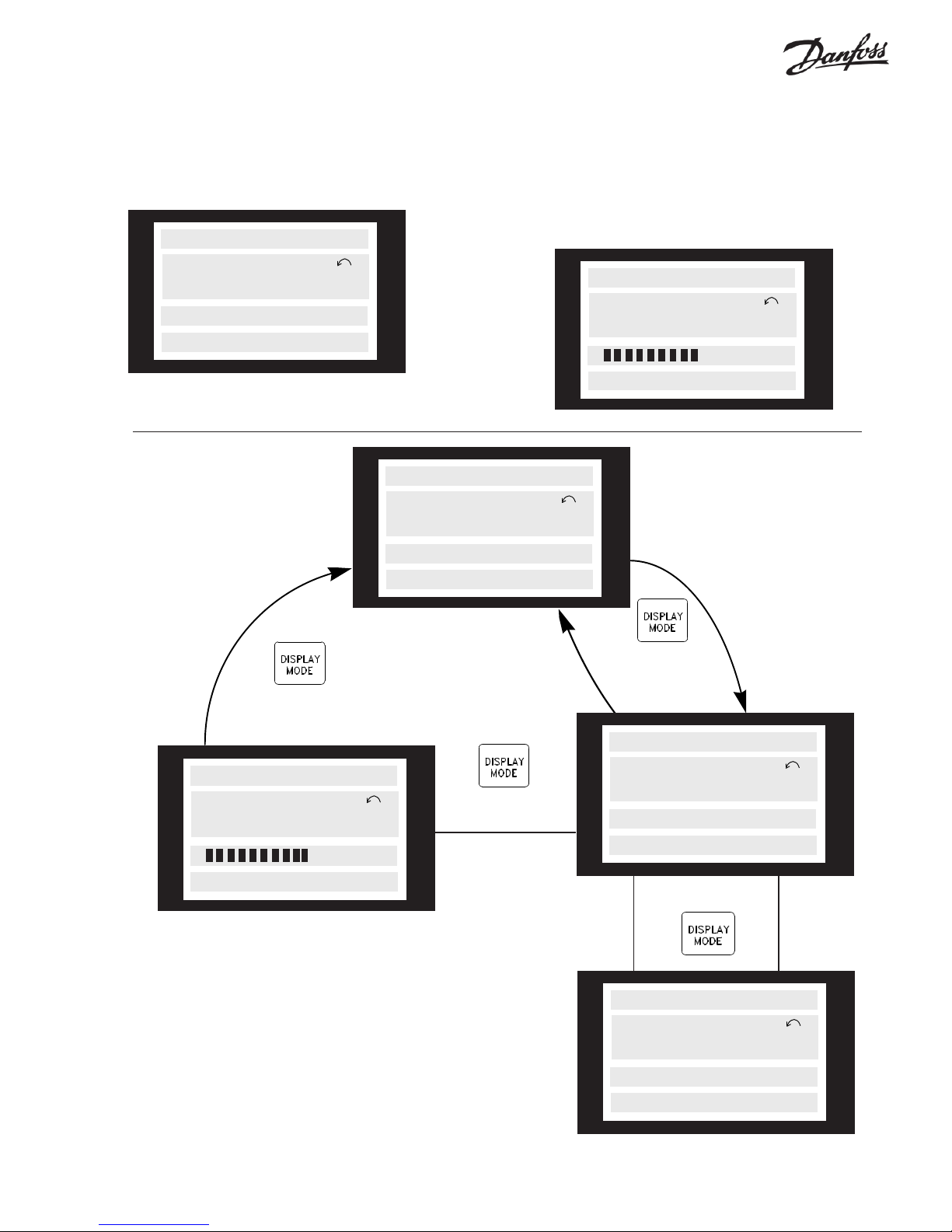
Display Mode III:
This display mode is shown when the drive is in Display Mode II and the
Display Mode key is pressed and held. In the first line, a description of
the three top meters in Display Mode II is shown. The other lines are
unchanged. When the key is released, Display Mode II is again shown.
REF% CURR.A POW. kW
Display Mode IV:
This display mode is available when local reference is selected. In this
display mode, the speed reference is increased or decreased via +/- keys.
The first line shows the present speed reference. The second line
shows the present drive output frequency. The third line show a bar
graph of the relative value of the present drive output frequency in
relation to the maximum frequency.
50.0Hz
AUTO REMOTE RUN
Navigation Between
Display Modes
With local reference
SETUP
1
FREQUENCY
40.0Hz
AUTO REMOTE
RUNNING
Display Mode I
USE +/- 56Hz
40Hz
0 -----60
HAND LOCAL
RAMPING
SETUP
1
With remote
controlled reference
SETUP
1
With local/remote
reference
USE +/- 56Hz
SETUP
40.0Hz
0 ----60
HAND LOCAL
RAMPING
Display Mode IV
1
With local reference
▲▲
▲▲
▲
Keep DISPLAY
MODE key down
80% 7.8A 5.9kW
SETUP
40.0Hz
AUTO REMOTE RUN
Display Mode II
▲▲
▲
▲▲
REF% CURR.A POW. kW
40.0Hz
AUTO REMOTE RUN
Display Mode III
1
▼▼
▼
▼▼
Release DISPLAY
MODE key
SETUP
1
25
Page 26
Quick Menu
The QUICK MENU key gives access to 12 of the most important setup
parameters of the drive. After programming, the drive will, in many
cases, be ready for operation. The 12 Quick Menu parameters are
Quick Menu Parameter Description
Item Number Name
1 001 Language Selects language used for all displays.
2 102 Motor Power Sets output characteristics of drive based on kW (HP) of motor. See
chart in parameter 102, Motor Power, to convert HP to kW.
3 103 Motor Voltage Sets output characteristics of drive based on voltage of motor .
4 104 Motor Frequency Sets output characteristics of drive based on nominal frequency of
motor. This is typically equal to line frequency .
5 105 Motor Current Sets output characteristics of drive based on full load current in amps
(FLA) of motor. This sets overload protection for motor .
6 106 Motor Nominal Speed Sets output characteristics of drive based on nominal full load speed of
motor.
7 201 Minimum Frequency Sets minimum controlled frequency at which motor will run.
8 202 Maximum Frequency Sets maximum controlled frequency at which motor will run.
9 206 Ramp Up Time Sets time to accelerate motor from 0 Hz to nominal motor frequency
set in Quick Menu Item 4.
10 207 Ramp Down Time Sets time to decelerate motor from nominal motor frequency set in
Quick Menu Item 4 to 0 Hz.
1 1 323 Relay 1 Function Sets function of high voltage Form C relay.
12 326 Relay 2 Function Sets function of low voltage Form A relay.
shown in the table below. A complete description of the function is given
in the parameter sections of this manual.
To Enter or Change Quick Menu Parameter Data
Enter or change parameter data or settings in accordance with the
following procedure.
1. Press Quick Menu key.
2. Use ‘+’ and ‘-’ keys to find parameter you chose to edit.
3. Press Change Data key.
4. Use ‘+’ and ‘-’ keys to select correct parameter setting. T o move to
a different digit within parameter , use J and K arrows. Flashing
cursor indicates digit selected to change.
5. Press Cancel key to disregard change, or press OK key to accept
change and enter new setting.
Example of Changing Parameter Data
Assume Parameter 206, Ramp Up Time, is set at 60 seconds. Change
the ramp up time to 100 seconds in accordance with the following
procedure.
1. Press Quick Menu key.
2. Press ‘+’ key until you reach Parameter 206, Ramp Up Time.
3. Press Change Data key.
4. Press J key twice – hundreds digit will flash.
5. Press ‘+’ key once to change hundreds digit to ‘1.’
6. Press K key to change to tens digit.
7. Press ‘-’ key until ‘6’ counts down to ‘0’ and setting for Ramp Up
Time reads ‘100 s.’
8. Press OK key to enter new value into drive controller.
NOTE
Programming of extended parameters functions
available through Extended Menu key is done
in accordance with same procedure as described for Quick Menu functions.
26
Page 27
Extended Menu
CAUTION
!
In some applications, the Quick Menu items will not set up all the
desired characteristics of the drive. T o access all the parameters,
including the Quick Menu parameters, press the Extend Menu key. The
Programming section of this manual will describe in detail all the
parameters available through the Extended Menu.
Step Change of Numeric Values
The values of certain numeric items can also be selected from a list.
These parameters are Motor Power, parameter 102; Motor Voltage,
parameter 103; and Motor Frequency, parameter 104. T o select a
value not on the list, use the L and M keys to select the digit to be
changed, as described above.
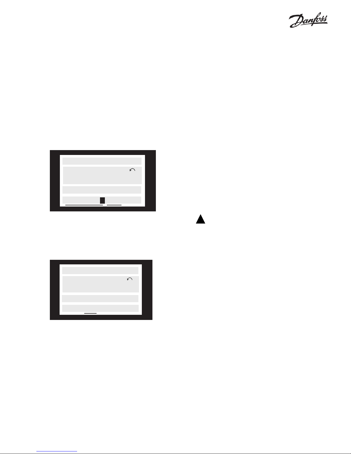
Changing Data
T o change any parameter in either the Quick Menu mode or the
Extended Menu mode, press the CHANGE DAT A key. When the
CHANGE DAT A key is pressed, the data in line four will be underlined,
and a cursor will be shown if the parameter controls numeric data.
The procedure for changing data depends on whether the value of the
parameter is a number or a item from a list.
FREQUENCY
SETUP
24.2 Hz
1
205 MAX. REFERENCE
000060.000 Hz
Parameter is a Number
T o change a number , move the cursor to the digit to be changed by
using the LM keys. Then change the digit by using the + and - keys.
MOTOR CURRENT
SETUP
3.90 A
1
210 REFERENCE
TYPE SUM
Parameter is a Value Chosen from a List
Manual Initialization of Parameters
It is possible to reset nearly all parameters back to their original default
values at once. T o reset the drive parameters to their read only memory
default values, remove power from the drive. Press and hold the Display
Mode, Change Data and OK keys down while reapplying power. Shortly
after power is reapplied, the bottom line of the display will read “Initialized”. After the display stops changing, release the keys. If “Initialized” did
not appear, repeat the procedure.
These parameters are not reset by manual initialization:
Parameter 600 Operating hours
Parameter 601 Hours run
Parameter 602 kWh counter
Parameter 603 Number of power-ups
Parameter 604 Number of overtemperatures
Parameter 605 Number of overvoltages
Initialization can also be done using Parameter 620.
Manual initialization using either this procedure
or parameter 620 will reset drive to standard default parameters. Any special programming for
application that was performed at factory, during
start-up or subsequently, will be lost. If desired
parameters have been previously stored in drive’s
local control panel (LCP), it may be better to download those parameters from LCP using parameter
download functions of parameter 004.
Uploading Parameters
At any time the present parameters may be copied to the local control
panel (LCP). This may be useful when setting up multiple drives. It is
also useful when it is desired to return to a previous set of parameters.
See parameter 004, LCP Copy, for more information.
If the selected parameter’s value is selected from a list, its value can be
changed by using the + and - keys.
When the desired value is displayed, press the OK key to accept the new
value. If you wish to cancel the change and return to the previously
accepted value, press the CANCEL key . If neither OK nor CANCEL is
pressed, the new value will be accepted after 20 seconds.
Manually initializing the drive using either the procedure described
above or parameter 620, Operating Mode, does not change the
values uploaded to the local control panel.
27
Page 28

VLT 6000 Start-Up
Pre-installation Checks
1. Compare drive model number to what was ordered.
2. Ensure each of following are rated for same voltage:
• Drive
• Power line
• Motor
3. Record following motor data:
• Voltage
• Frequency
• Full load current
• Full load speed
• Power — convert HP to kW (See conversion table in parameter
102, Motor Power, in this manual.)
4. Ensure that rated drive current is equal to or greater than total full
load current.
• For multiple motor operations, add up full load current ratings of
all motors.
• Drive can be at most one size smaller than motor.
• If drive rating is less than motor, full motor output cannot be achieved.
5. Check motor wiring:
• Any disconnect between drive and motor should be interlocked
to drive safety interlock circuit to avoid unwanted drive trips.
• No power factor correction capacitors can be connected between
drive and motor.
• Two speed motors must be wired permanently for full speed.
• Y-start, H-run motors must be wired permanently for run.
Installation Checks
1. Input fusing in power supply for all drives must be provided (see
Input Fuses section in this manual).
2. Environmental concerns — for standard NEMA 1 drive:
• Clean air supply
• Dry air (max 95% relative humidity , non-condensing)
o
• 14
F to 104oF ambient temperature operating range, or as rated
• 3,300 foot maximum elevation with no derating
3. Mounting
• Vertical
• Drives with heat sink fins exposed in back of unit must be
mounted against a solid surface (see Clearances section in this
manual).
• Keep any construction dirt out of drive.
4. Wiring
• Wire drive in accordance with instructions and diagrams received
with drive.
• Separate conduits must be provided to drive for input power,
output power, and control wiring.
• Note that safety interlock and remote run/stop circuitry is 115 V AC
for drives with bypasses.
• Use knockouts or conduit entry plates. Avoid metal shavings in cabinet.
• Protect signal wires from noise.
• Ground each drive individually.
• Double check input and output power wiring for correct location.
Setting Up Drive for Motor Start
Enter motor nameplate data into drive through Quick Menu.
1. Parameter 101:
• If one motor is connected to drive, set to AEO FUNCTION.
• If more than one motor connected to drive, set to MULTIPLE
MOTORS. (Parameter 108, MUL TIPLE MOTOR ST ARTING
VOLT AGE should be adjusted later to provide reliable starts and
minimum starting current.)
2. Parameter 102, MOTOR POWER (in kW) (See conversion table in
parameter 102, Motor Power, in this manual.)
3. Parameter 103, MOTOR VOLT AGE
4. Parameter 104, MOTOR FREQUENCY
5. Parameter 105, MOTOR CURRENT
6. Parameter 106, MOTOR SPEED
7. Parameter 107, (optional) select AUTOMATIC MOTOR ADAPT ATION and run AMA in accordance with procedure in parameter
107, Automatic Motor Adaptation, in this manual.
8. Press HAND STAR T key to initiate operation in local control.
Operational Tests — HAND
1. Check motor rotation from drive. If incorrect, disconnect input
power from drive and reverse two leads between drive and motor.
2. If a bypass is provided, check motor rotation in bypass mode. If
incorrect, disconnect input power from drive and reverse two input
power leads.
3. Accelerate motor quickly to full speed and verify operation.
4. Decelerate motor quickly to stop and verify operation.
5. Operate motor over entire speed range while closely checking for
resonance.
Operational Tests — AUTO
1. Ensure that drive follows run/stop and safety interlock commands
from system.
2. Ensure drive follows speed reference, or feedback, from system.
Final Adjustments
1. Use parameters 216 through 220 to reject any resonant points.
2. Lock out keypad functions, as required.
General Troubleshooting
1. Display Messages:
• AUTO ST ART—Drive has tripped off and is in process of
automatically restarting.
• TRIP—Drive has tripped off. Press RESET to start.
• TRIP LOCKED—Drive has tripped off. Remove and apply
power before restarting with RESET .
2. Refer to Warnings and Alarms section in this manual.
3. Check tightness of all connections and wires for proper location.
4. Measure input signals.
5. Check drive input and output for balanced voltage and current.
28
Page 29

Programming
Using the Extend Menu key, it is possible to access to all
the parameters for the drive.
Operation and Display
Parameters 000 through 017
This parameter group deals with the display, control keys and other
general functions.
Description of Parameters
Parameters are grouped by function. The groups are:
Operation and Display Parameters 001 through 017
Load and Motor Parameters 100 through 117
References and Limits Parameters 200 through 228
Input and Outputs Parameters 300 through 328
Appli cat ion Func tio ns Parameters 400 through 427
Serial Communication Parameters 500 through 566
Service Functions Parameters 600 through 631
Relay Card Functions Parameters 700 through 711
The numbers shown in the square brackets ([ ]) after the parameter
values are used in serial communications to choose the parameter
value from the list. They are not shown on the local control panel when
programming the drive locally.
Setup Configuration
The drive has four setups that can be programmed independently. The
active setup can be selected in parameter 002, Active Setup. The
active setup number is shown on the right of line two in the display
under the word “Setup.”
It is also possible to set the drive to Multi-Setup to allow switching
setups through digital inputs or serial communication.
More than one setup can be used. An example would be a changing
setups for day/night or summer/winter operation.
Parameter 003, Copying of Setups, enables copying from one setup to
another.
By means of parameter 004, LCP Copy, any setup can be transferred
from one drive to another using the removable local control panel
(LCP). First, upload all parameter values to the control panel installed
in the drive. Insert this panel into the next drive. Download all
parameter values from the control unit to the second drive. Repeat this
procedure to program additional drives.
001 Language (Language)
Value:
✭ English (ENGLISH) [0]
German (DEUTSCH) [1]
French (FRANCAIS) [2]
Danish (DANSK) [3]
Spanish (ESP A¥OL) [4]
Italian (ITALIANO) [5]
Swedish (SVENSKA) [6]
Dutch (NEDERLANDS) [7]
Portuguese (PORTUGUESA) [8]
Function:
This parameter determines the language to be used on the display .
Description of choice:
There is a choice of the languages indicated.
002 Active Setup (ACTIVE SETUP)
Value:
Factory Setup (FACTOR Y SETUP) [0]
✭ Setup 1 (SETUP 1) [1]
Setup 2 (SETUP 2) [2]
Setup 3 (SETUP 3) [3]
Setup 4 (SETUP 4) [4]
Multi-Setup (MULTI SETUP) [5]
Function:
This parameter defines the setup number that controls the drive.
All parameters can be programmed in four individual parameter setups,
Setup 1, Setup 2, Setup 3 and Setup 4.
In addition, a pre-programmed read-only setup, called the Factory
Setup, exists.
Description of choice:
Factory Setup contains the parameter values preset at the factory. This
setup can be used as a data source if the other setups are to be
returned to a known state.
Setups 1 through 4 are four individual setups that can be selected as
required.
✭ Indicates default parameter. Depending upon the application, the drive may be delivered with other parameters selected.
Multi-Setup is used if remote switching between different setups is
required. T erminals 16, 17, 29, 32, 33 and the serial communication
port can be used for switching between setups.
29
Page 30
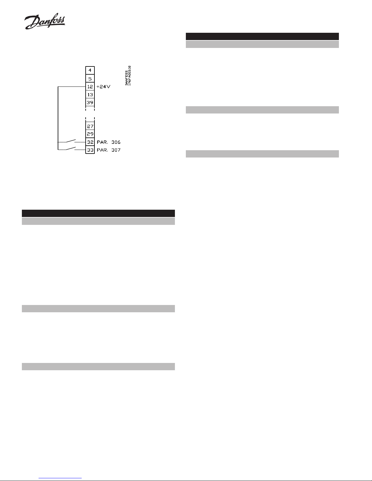
Connection Examples:
Setup Change
Selection of setup using terminals 32 and 33.
See the descriptions of parameters 300 through 307.
Parameter 306 = Selection of Setup, lsb
Parameter 307 = Selection of Setup, msb
Parameter 002 = Multi Setup
004 LCP Copy (LCP COPY)
Value:
✭ No copying (NO COPY) [0]
Upload all parameters
(UPLOAD ALL PARAMET.) [1]
Download all parameters
(DOWNLOAD ALL PARAM.) [2]
Download power-independent parameters
(DOWNLOAD SIZE INDEP .) [3]
Function:
Parameter 004, LCP Copy, is used to copy all parameter setups to or
from the Local Control Panel (LCP). This can be used to store a
backup copy of all parameters in the LCP or to copy all setups from
one drive to another.
Description of choice:
Select Upload all parameters if all parameter values are to be copied
from the drive to the LCP .
Select Download all parameters if all parameter values are to be
copied from the LCP to the drive on which the control panel has been
mounted.
003 Copying of Setups (Setup Copy)
Value:
✭ No copying (NO COPY) [0]
Copy active Setup to Setup 1
(COPY TO SETUP 1) [1]
Copy active Setup to Setup 2
(COPY TO SETUP 2) [2]
Copy active Setup to Setup 3
(COPY TO SETUP 3) [3]
Copy active Setup to Setup 4
(COPY TO SETUP 4) [4]
Copy active Setup to all (COPY TO ALL) [5]
Function:
A copy is made from the active setup selected in parameter 002, Active
Setup, to the setup or setups selected in parameter 003, Copying of
Setups.
NOTE
Copying is only possible when drive is stopped.
Description of choice:
The copying starts when the required copying function has been
selected and the OK key has been pressed.
Select Download power-independent parameters if only the powerindependent parameters are to be downloaded. This allows the
parameters from one drive to be easily copied to another drive of a
different size.
NOTE
Copying is only possible when drive is stopped.
Setup of User-Defined Readout
Parameter 005, Maximum Value of User-Defined Readout, and
Parameter 006, Unit for User-Defined Readout, allow users to design
their own readout which can be seen if the User-Defined Readout has
been selected as one of the displayed meters. The range is set in
parameter 005, Maximum Value of User-Defined Readout and the unit
is determined in parameter 006, Unit for User-Defined Readout. The
choice of unit determines whether the relationship between the output
frequency and the readout is a linear, square or cubed. Units
representing rates (RPM, CFM, GPM, etc.) are linear. Units representing pressure (PSI, in. wg., etc.) are square. Units representing power
(HP , kW , etc.) are cubed.
The display indicates when copying is in progress.
✭ Indicates default parameter. Depending upon the application, the drive may be delivered with other parameters selected.
30
Page 31

005 Maximum Value of User-Defined Readout
(CUSTOM READOUT )
Value:
0.01 - 999,999.99 ✭100.000
Function:
This parameter determines the value that the user defined meter will
display when the drive’s output frequency is the value set in parameter
202, Output Frequency High.
Description of choice:
Set the required value for maximum output frequency.
006 Unit for User Defined Readout
(CUST. READ. UNIT)
Value:
1
No unit
✭ %
1
Linear units (flow or speed)
2
Squared units (pressure)
3
Cubed units (power)
1
1
rpm
1
ppm
pulse/s
1
l/s
1
l/min
1
l/h
1
kg/s
kg/min
1
kg/h
1
m3/s
m3/min
1
m3/h
1
m/s
2
mbar
2
bar
2
Pa
2
MPa
MWG
3
kW
1
1
1
2
[0] GPM
[1] gal/s
[2] gal/min
[3] gal/h
[4] lb/s
[5] lb/min
[6] lb/h
[7] CFM
[8] ft3/s
[9] ft3/min
[10] ft3/h
[11] ft3/min
[12] ft/s
[13] in wg
[14] ft wg
[15] PSI
[16] lb/in
[17] HP
[18]
[19]
[20]
1
1
1
1
1
1
1
1
1
1
1
1
1
2
2
2
2
3
[21]
[22]
[23]
[24]
[25]
[26]
[27]
[28]
[29]
[30]
[31]
[32]
[33]
[34]
[35]
[36]
[37]
[38]
Function:
Select a unit to be shown with the display of the User Defined Readout.
If flow or speed units are selected, the relationship between readout
and output frequency will be a linear one. If pressure units are
selected, the ratio will be square. If power units are selected, the ratio
will be cubed.
The value and the unit are shown in display mode whenever User
Defined Readout has been selected in one of parameters 007 through
010, Display Readout.
Description of choice:
Select the required unit for User Defined Readout.
007 Large Display Readout (LARGE READOUT)
Value:
Resulting reference [%] (REFERENCE [%]) [1]
Resulting reference [unit] (REFERENCE [UNIT]) [2]
Frequency [Hz] (FREQUENCY [HZ]) [3]
✭ % of maximum output frequency [%]
(FREQUENCY [%]) [4]
Motor current [A] (MOTOR CURRENT [A]) [5]
Power [kW] (POWER [KW]) [6]
Power [HP] (POWER [HP]) [7]
Output energy [kWh] (ENERGY [UNIT]) [8]
Hours run [Hours] (HOURS RUN [h]) [9]
User-defined readout [-]
(CUSTOM READ. [UNITS]) [10]
Setpoint 1 [unit] (SETPOINT 1 [UNITS]) [11]
Setpoint 2 [unit] (SETPOINT 2 [UNITS]) [12]
Feedback 1 (FEEDBACK 1 [UNITS]) [13]
Feedback 2 (FEEDBACK 2 [UNITS]) [14]
Feedback [unit] (FEEDBACK [UNITS]) [15]
Motor voltage [V] (MOTOR VOL T AGE [V]) [16]
DC link voltage [V] (DC VOLTAGE [V]) [17]
Thermal load, motor [%]
(THERM.MOTOR LOAD [%]) [18]
Thermal load, VLT [%] (THERM.DRIVE LOAD [%]) [19]
Digital input [Binary code] (DIGITAL INPUT [BIN]) [20]
Analog input 53 [V] (ANALOG INPUT 53 [V]) [21]
Analog input 54 [V] (ANALOG INPUT 54 [V]) [22]
Analog input 60 [mA] (ANALOG 60 [mA]) [23]
Pulse reference [Hz] (PULSE REFERENCE [Hz]) [24]
External reference [%] (EXT. REFERENCE [%]) [25]
Heat sink temp. [oC] (HEATSINK TEMP [oC]) [26]
Free programming array (FREE PROG. ARRAY) [27]
✭ Indicates default parameter. Depending upon the application, the drive may be delivered with other parameters selected.
31
Page 32

Function:
This parameter allows a choice of the data value to be shown in large
digits on line two of the display when power is first applied to the drive.
In Display Mode I, II, and III, the + and - keys allow the display on this
line to be changed when the drive is in operation.
DC link voltage [V] is the drive DC bus voltage.
Thermal load, motor [%] is the calculated thermal load of the motor.
100% is the cutout limit. See also parameter 117, Motor Thermal
Protection.
Description of choice:
No readout can only be selected in parameters 008 through 010, Small
Display Readout, but not in parameter 007, Large Display Readout.
Resulting reference [%] gives the total of all references as a
percentage of parameter 205, Maximum Reference.
Reference [unit] gives the total of all references. This is displayed in
Hz in open loop. In closed loop, the reference unit is selected in
parameter 415, Process Units.
Frequency [Hz] gives the output frequency of the drive.
% of maximum output frequency [%] is the output frequency as a
percentage of parameter 202, Output Frequency High Limit.
Motor current [A] is the average phase current of the motor.
Power [kW] is the actual power, in kW , delivered to the motor .
Power [HP] is the actual power, in HP, delivered to the motor.
Output energy [kWh] is the energy delivered by the motor since the
latest reset was made using parameter 618, Reset of kWh Counter.
Hours run [Hours] is the number of hours that the motor has run
since the latest reset was made using parameter 619, Reset of Hours
Run Counter.
User Defined readout [-] is a user defined value, calculated on the
basis of the present output frequency, as well as the scaling in
parameter 005, Maximum V alue of User-Defined Readout, and the
unit in parameter 006, Unit for User-Defined Readout.
Setpoint 1 [unit] is the setpoint value programmed in parameter 418,
Setpoint 1. The unit is selected in parameter 415, Process Units.
Setpoint 2 [unit] is the setpoint value programmed in parameter 419,
Setpoint 2. The unit is selected in parameter 415, Process Units.
Thermal load, VLT [%] is the calculated thermal load of the drive.
100% is the trip point.
Digital input [Binary code] is the signal status from the 8 digital
inputs (16, 17, 18, 19, 27, 29, 32 and 33). T erminal 16 corresponds to
the bit at the far left. ‘0’ = no signal, ‘1’ = connected signal.
Analog input 53 [V] is the voltage applied to terminal 53.
Analog input 54 [V] is the voltage applied to terminal 54.
Analog input 60 [mA] is the current applied to terminal 60.
Pulse reference [Hz] is the pulse frequency in Hz applied to terminal
17 or terminal 29.
External reference [%] is the sum of the external references as a
percentage of parameter 205, Maximum Reference.
Heat sink temp. [°C] is the present heat sink temperature of the drive.
The trip point is 90 ± 5°C for NEMA 1 units and 80 ± 5°C for NEMA 12
units.
Free Programming Array is reserved for future use. It is only
available in parameter 007, Large Display Readout.
008 Small Display Readout 1.1
(SMALL READOUT 1)
Value:
See parameter 007, Large Display Readout
✭ Reference, %
Function:
This parameter selects the meter to be displayed on the left display on
line 1.
Showing three different meters on line 1 is recommended when setting
up the PID. This allows tracking how the process reacts to a change of
reference.
Feedback 1 [unit] is the value of the feedback signal applied to
T erminal 53. The unit is selected in parameter 415, Process Units.
Feedback 2 [unit] is the value of the feedback signal applied to
T erminal 54. The unit is selected in parameter 415, Process Units.
Feedback [unit] is the total feedback signal using the unit scaling
selected in parameter 413, Minimum Feedback; parameter 414
Maximum Feedback; parameter 415, Process Units; and parameter
417, 2 Feedback Calc.
Motor voltage [V] is the voltage supplied to the motor.
✭ Indicates default parameter. Depending upon the application, the drive may be delivered with other parameters selected.
32
T o select the meter to display , press the Display Mode button.
Description of choice:
There is a choice of 26 different meters. See parameter 007, Large
Display Readout.
009 Small Display Readout 1.2
(SMALL READOUT 2)
Value:
See parameter 007, Large Display Readout
★ Motor current [A]
Page 33

Function:
CAUTION
!
CAUTION
!
See the functional description for parameter 008, Small Display
Readout.
Description of choice:
There is a choice of 26 meters, see parameter 007 Large Display
Readout.
010 Small Display Readout 1.3
(SMALL READOUT 3)
Value:
See parameter 007 Large Display Readout
★ Power [HP]
If
Disable
by Off/Stop key.
014 Auto Start on LCP (AUTO START BTTN)
Value
Disable (DISABLE) [0]
★ Enable (ENABLE) [1]
Function:
This parameter allows disabling the Auto/Start key on the keypad.
is selected, motor cannot be stopped
Function:
See the functional description for parameter 008 Small Data Readout.
Description of choice:
There is a choice of 26 different data values, see parameter 007 Large
Display Readout.
011 Unit of Local Reference (UNIT OF LOC REF)
Value:
Hz (HZ) [0]
★ % of output frequency range (%) (% OF FMAX) [1]
Function:
This parameter sets the unit that will be displayed in Display Mode IV
when the drive’s speed is being controlled locally .
Description of choice:
Choose the desired unit for local reference.
012 Hand Start on LCP (HAND START BUTTON)
Value:
Disable (DISABLE) [0]
★ Enable (ENABLE) [1]
Function:
This parameter allows disabling the Hand/Start key on the keypad.
Description of choice:
If Disable is selected in this parameter , the Hand/Start key will be
disabled.
013 OFF/STOP on LCP (STOP BUTTON)
Value:
Disable (DISABLE) [0]
★ Enable (ENABLE) [1]
Function:
This parameter allows disabling the Off/Stop key on the keypad.
Description of choice:
If Disable is selected in this parameter , the Off/Stop key will be disabled.
Description of choice:
If Disable is selected in this parameter , the Auto/Start key will be
disabled.
P 015
015 Reset on LCP (RESET BUTTON)
Value:
Disable (DISABLE) [0]
★ Enable (ENABLE) [1]
Function:
This parameter allows disabling the Reset key on the keypad.
Description of choice:
If Disable is selected in this parameter , the Reset key will be inactive.
Do not disable Reset unless a remote reset is
available through digital inputs and parameters
300 through 307.
016 Lock for Data Change (DATA CHANGE LOCK)
Value:
★ Not Locked (NOT LOCKED) [0]
Locked (LOCKED) [1]
Function:
This parameter allows locking out parameter changes at the local
control panel.
Description of choice:
If Locked is selected, data modifications in the parameters cannot be
made. Parameter changes will be possible through serial communication.
Parameters 007 through 010, Display Readout can be changed at the
local control panel.
The local control panel can also be locked or unlocked by a digital
input controlled by parameters 300 through 307.
✭ Indicates default parameter. Depending upon the application, the drive may be delivered with other parameters selected.
33
Page 34

017 Operating State at Power Up
(POWER UP ACTION)
Value:
★ Auto restart (AUTO REST ART) [0]
OFF/STOP (OFF/STOP) [1]
Function:
Selects auto or manual restart when power is reapplied after an outage
occurs to a running drive.
Description of choice:
Auto restart is selected if the drive is to resume operation after a power
outage.
OFF/STOP is selected if the drive is to remain stopped after a power
outage. T o restart, press the Hand/Start or Auto/Start key at the
keypad.
CAUTION
!
If HAND/START or AUTO/START are disabled
by parameters 012 and 014, motor will not be
able to restart if
OFF/STOP
is selected.
Load and Motor
Parameters 100 through 117
This parameter group controls output power and other output
characteristics of the drive.
For correct operation, motor nameplate data must be entered into
parameters 102 through 106 either through the Quick Menu or the
Extended Menu. In addition, automatic motor adaptation, DC braking
and motor thermal protection can be set by this parameter group.
NOTE
If Open Loop is selected, parameters associated with setting up PID controller are not
accessible. Therefore, it is important to properly set parameter 100,
closed loop operation is required.
Characteristics
101 Torque Characteristics ( VT CHARACT)
Value:
★ Automatic Energy Optimization
(AEO FUNCTION) [0]
Parallel motors (MULTIPLE MOTORS) [1]
Function:
This parameter configures the drive for single or multiple motor
operation.
Description of choice:
Select Automatic Energy Optimization (AEO) for all single motor
applications. When AEO has been selected, only one motor may be
connected to the drive at a time.
The AEO function will automatically and continuously monitor the load
and adjust the output voltage to maximize motor and drive efficiency
and performance. After the motor reaches the set speed, the AEO
function reduces the output voltage to the motor, if the load will allow .
When the load is light, the voltage is reduced, as shown in the graph
below. This lower voltage reduces motor heating and motor noise, and
increases efficiency .
Select Parallel motors when more than one motor is connected in
parallel to the output. In this case, it is necessary to set a start voltage in
parameter 108, Start Voltage of Parallel Motors.
Configuration
, first when
100 Configuration (CONFIG. MODE)
Value:
★ Open loop (OPEN LOOP) [0]
Closed loop (CLOSED LOOP) [1]
Function:
This parameter is used for selecting closed loop or open loop
operation.
Description of choice:
If Open loop is selected, speed control is changed directly by the
speed reference signal. Any feedback signal applied to the drive will
have no effect on the drive’s speed.
If Closed loop is selected, the internal process regulator is available to
accept feedback signal(s) to provide the desired speed regulation.
✭ Indicates default parameter. Depending upon the application, the drive may be delivered with other parameters selected.
34
Page 35

CAUTION
!
It is very important that values set in param-
CAUTION
!
eters 102,
Speed,
of motor.
102 Motor Power (MOTOR POWER)
Value:
0.25 kW (0.33 HP) [25]
0.37 kW (0.5 HP) [37]
0.55 kW (0.75 HP) [55]
0.75 kW (1 HP) [75]
1.1 kW (1.5 HP) [110]
1.5 kW (2 HP) [150]
2.2 kW (3 HP) [220]
3 kW -- [300]
4 kW (5 HP) [400]
5.5 kW (7.5 HP) [550]
7.5 kW (10 HP) [750]
1 1 k W (15 HP) [1 100]
15 k W (20 HP) [1500]
18.5 kW (25 HP) [1850]
22 k W (30 HP) [2200]
30 k W (40 HP) [3000]
37 k W (50 HP) [3700]
45 k W (60 HP) [4500]
55 k W (75 HP) [5500]
75 k W (100 HP) [7500]
90 k W (125 HP) [9000]
110 kW (150 HP) [11000]
132 kW (175 HP) [13200]
160 kW (200 HP) [16000]
200 kW (300 HP) [20000]
250 kW -- [25000]
300 kW -- [30000]
315 kW (350 HP) [31500]
355 kW (450 HP) [35500]
400 kW (500 HP) [40000]
500 kW (600 HP) [50000]
★ Depends on the unit
Function:
Set the power value that corresponds to the nameplate power of the
motor. The default setting is the full rating of the drive.
Description of choice:
Select a value that equals the nameplate data on the motor. It is also
possible to set any power within the range of the drive.
Motor Power,
correspond accurately to nameplate data
through 106,
Rated Motor
103 Motor Voltage (MOTOR VOLTAGE)
Value:
200 V [200]
208 V [208]
220 V [220]
230 V [230]
240 V [240]
380 V [380]
400 V [400]
415 V [415]
440 V [440]
460 V [460]
480 V [480]
500 V [500]
575 V [575]
★ Depends on the unit
Function:
Set the rated motor voltage.
Description of choice:
Select a value that equals the nameplate data on the motor. This may
be less than the input voltage. It is also possible to set any voltage
within the range of the drive.
104 Motor Frequency (MOTOR FREQUENCY)
Value:
50 Hz (50 Hz) [50]
★ 60 Hz (60 Hz) [60]
Function:
This is where the rated motor frequency is selected. This is usually the
frequency of the power line.
Description of choice:
Select the desired value. It is also possible to set any frequency within
the range of the drive.
Enter correct value in parameter 105,
rent
, since this forms part of VVC+ control.
Changing values in parameter 102,
or parameter 103,
current has been entered in parameter 105 can
automatically change the value in parameter 105.
105 Motor Current (MOTOR CURRENT)
Value:
0.01 to drive rating
Function:
The rated motor current in amps is used for setting output current and
providing motor thermal protection. It is important to set the motor
current to the full load current rating (FLA) of the motor.
Motor Voltage,
★ Set based on motor nameplate.
Motor Cur-
Motor Power
after motor
,
✭ Indicates default parameter. Depending upon the application, the drive may be delivered with other parameters selected.
Description of choice:
Set a value that equals the nameplate data on the motor.
35
Page 36

CAUTION
!
It is important to set correct value in parameter
106,
Rated Motor Speed
of VVC+ control feature. Changing value in parameter 104,
speed has been entered in parameter 106 may
automatically change the value in parameter 106.
106 Rated Motor Speed (MOTOR NOM. SPEED)
Value:
100 through 60000
✭ Depends on parameter 102, Motor Power
Function:
This is where the value is set that corresponds to the rated motor
speed shown on the motor nameplate.
Description of choice:
Choose a value that corresponds to the motor nameplate data.
107 Automatic Motor Adaptation, AMA
(AUTO MOTOR ADAPT)
Value:
★ Optimization disable (NO AMA) [0]
Automatic adaptation (RUN AMA) [1]
Automatic adaptation with LC-filter
(RUN AMA WITH LC-FILT) [2]
Function:
Automatic Motor Adaptation (AMA) is an advanced procedure that
measures electrical characteristics of the motor. This procedure does
not run the motor.
AMA optimizes the adjustment of the drive to the motor. This feature is
particularly useful with nonstandard motors, higher HP motors, and
when the drive-to-motor cable length is long. Although it is not
necessary to run AMA, it is highly recommended for optimum operation
and increases the capability of the Automatic Energy Optimization
function selectable in parameter 101, T orque Characteristics.
Motor Frequency
, since this forms part
, after rated motor
NOTE
Some motors may be unable to run AMA.
tomatic Motor Adaptation with LC-Filter
reduced AMA procedure which can be effective
in such cases when run without an LC-filter installed since results measure motor’s stator and
effects of cable length.
The following must be noted when the AMA function is used:
- Before running AMA, the correct nameplate data for the motor
must be entered in parameters 102 to 106.
- T otal automatic motor adaptation may take up to 10 minutes.
- Alarms and warnings will be shown in the display if faults occur
during motor adaptation.
- AMA can only be carried out if the rated motor current of the motor
is at least 35% of the rated output current of the drive.
- To cancel AMA, press the OFF/STOP key .
CAUTION
!
AMA cannot be used on multiple motor applications.
Description of choice:
Select Automatic Adaptation if the drive is to carry out a complete
automatic motor adaptation procedure.
Select Automatic Adaptation with LC-Filter if an LC-filter has been
placed between the drive and the motor or to run a reduced AMA
without an LC-filter installed.
Au-
is a
Procedure for Automatic Motor Adaptation:
1. Set motor parameters, 102 through 106, according to motor
nameplate data.
2. Connect 24 VDC from terminal 12, or external to drive, to
terminal 27.
3. Select either Automatic Adaptation or Automatic Adaptation with
LC-Filter in parameter 107, Automatic Motor Adaptation, AMA.
4. Start drive by pressing Hand Start or connect terminal 18 (start) to
terminal 12 and press Auto Start.
For the best adjustment of the drive, it is recommended to carry out
AMA on a cold motor.
CAUTION
!
Repeated AMA runs may lead to a heating of
motor that will result in an increase of stator
resistance. This will reduce accuracy. Allow
motor to cool before running AMA.
If an output LC-filter has been connected between the drive and the
motor, select the Automatic Adaptation with LC-Filter. If the complete
AMA procedure is desired, remove the LC-filter, run Automatic
Adaptation (RUN AMA), and reinstall the filter .
✭ Indicates default parameter. Depending upon the application, the drive may be delivered with other parameters selected.
36
If the Automatic Motor Adaptation is to be stopped prior to completion:
Press OFF/STOP key .
After a normal sequence, the display reads: AMA STOP
1. Press RESET key . Drive is now ready for operation.
NOTE
RESET key must be pressed after AMA
is completed to load results into drive.
Page 37

If there is a fault, the display reads: ALARM 22
WARNING
!
WARNING
!
1. Press RESET key to clear fault.
2. Check alarms section in this manual for possible causes of alarm.
111 Start Delay (START DELAY)
Value:
0.0 to 120.0 sec. ★ 0.0 sec.
If there is a warning, the display reads: WARNING (39 through 42)
1. Check warnings section in this manual for possible causes of
warning.
2. Press CHANGE DATA key and select Continue if AMA is to
continue despite warning, or press OFF/STOP key to stop AMA.
108 Start Voltage of Parallel Motors
(MULTIM.START VOLT)
Value:
0.0 through parameter 103 Motor Voltage
✭ depends on par. 103 Motor V oltage
Function:
This parameter sets the voltage at 0 Hz for all drives with two or more
motors connected in parallel.
The start voltage represents a supplementary voltage input to the
motor. Increasing the start voltage will increase the starting torque. A
start voltage is especially useful for small motors (<5 HP) as they have
a higher stator resistance than larger motors.
This function is only active if Parallel Motors has been selected in
parameter 101, T orque Characteristics.
Description of choice:
T o set the start voltage, monitor the motor current while starting the load
and choose the starting voltage that gives the lowest starting current.
Start with a small value and increase only as required for reliable
starting.
109 Resonance Dampening (RESONANCE DAMP.)
Value:
0 to 500 % ★100 %
Function:
High-frequency resonances in the motor can be eliminated by adjusting
this parameter.
Description of choice:
Adjust the dampening percentage for smoothest high speed operation.
110 High Breakaway Torque (HIGH START TORQ.)
Value:
0.0 to 0.5 sec. ★ OFF
Function:
This parameter allows a delayed start of the drive after the conditions
for start have been fulfilled. After the start delay time has elapsed, the
drive will start and ramp up to the commanded speed.
Description of choice:
Set the desired time before the drive will start.
112 Motor Preheat (MOTOR PREHEAT)
Value:
✭ Disable (DISABLE) [0]
Enable (ENABLE) [1]
Function:
The motor preheat function protects the motor from condensation by
running a small DC current through the motor. Motor preheat is only
active during stop when control voltage is applied to terminal 27.
Description of choice:
Select Disable if this function is not required. Select Enable to activate motor
preheating. The amount of motor preheating is set in parameter 1 13.
Be sure to check parameter 113 if parameter
112,
Motor Preheat
rent or preheating time may damage motor.
113 Motor Preheat DC Current
(PREHEAT DC-CURR.)
Value:
0 to 100 % ★ 50 %
The maximum value depends on the rated motor current.
Function:
The motor can be preheated when stopped by applying DC current to
it. A holding torque can also be provided.
Description of choice:
The motor can be preheated by means of a DC current. At 0%, the
function is inactive; at a value higher than 0%, a DC current will be
supplied to the motor whenever it is stopped. A windmilling fan can be
held by providing a holding toque by using this parameter.
, is enabled. Excessive cur-
Function:
The drive is able to breakaway high friction loads. This high starting
torque, approximately 1.6 x rated torque is available for up to 0.5
seconds. The current level is limited by the protective circuits of the
drive. OFF corresponds to 0.0 sec.
Description of choice:
Set the time for which high starting torque is desired.
✭ Indicates default parameter. Depending upon the application, the drive may be delivered with other parameters selected.
Do not apply any more current than required.
Too high a current applied for too long a time
will overheat motor.
37
Page 38

DC Braking
Applying DC current to the motor will brake the motor. Parameter 1 14,
DC Braking Current, sets the DC braking current as a percentage of
the rated motor current. Parameter 115, DC Braking T ime, sets the
amount of time that the DC current will be applied. Parameter 116, DC
Brake Cut-in Frequency, sets the frequency at which DC braking
begins when the motor decelerates during a stop.
If terminal 19 or 27 (parameters 303 or 304 Digital Input) has been
programmed to DC Braking Inverse and shifts from logic ‘1’ to logic ‘0’,
the DC braking will be activated immediately.
When the start signal on terminal 18 changes from logic ‘1’ to logic ‘0’,
the DC braking will be activated when the output frequency becomes
lower than the brake cut-in frequency.
If a DC brake current is set in parameter 114, the drive’ s switching
frequency will be limited to 4 kHz during the braking.
WARNING
!
A high braking current supplied for a long time
will overheat motor. Use only the DC braking
current and time required.
CAUTION
!
Do not use DC braking function if inertia of
driven load is more than 20 times inertia of
motor.
115 DC Braking Time (DC BRAKE TIME)
Value:
0.0 to 60.0 sec. ✭ 10.0 sec.
Function:
This parameter sets the time that the DC braking is active.
Description of choice:
Set the desired time.
116 DC Brake Cut-in Frequency
(DC BRAKE CUT-IN)
Value:
0.0 (OFF) to setting of parameter 202 ✭ OFF
Function:
This parameter is used for setting the frequency at which DC braking
begins after a stop command is issued.
Description of choice:
Set the desired frequency for braking to begin upon deceleration.
CAUTION
!
Most HVAC applications do not required braking or holding. It is suggested that parameter
114 remains set at 0 unless unusual application requirements call for braking or holding
torque.
114 DC Braking Current (DC BRAKE CURRENT)
Value:
0 to 100% ★ 50 %
The maximum value depends on the rated motor current.
Function:
This parameter is used for setting the DC braking current that is
applied:
1. When the DC brake frequency set in parameter 116 DC Brake
Cut-in Frequency has been reached during a stop.
2. When DC brake inverse is active via terminal 19 or 27, or via the
serial bus.
The DC braking current will be active for the duration of the DC
braking time set in parameter 115 DC Braking T ime.
Description of choice:
T o be set as a percentage value of the rated motor current set in
parameter 105 Motor Current.
100% DC braking current corresponds to the value set in parameter
105.
✭ Indicates default parameter. Depending upon the application, the drive may be delivered with other parameters selected.
38
Page 39

117 Motor Thermal Protection
CAUTION
!
(MOT. THERM PROTEC)
Value:
No protection (NO PROTECTION) [0]
Thermistor warning (THERMISTOR WARNING) [1]
Thermistor trip (THERMISTOR FAUL T) [2]
ETR Warning 1 (ETR WARNING 1) [3]
✭ ETR Trip 1 (ETR TRIP 1) [4]
ETR Warning 2 (ETR WARNING 2) [5]
ETR Trip 2 (ETR TRIP 2) [6]
ETR Warning 3 (ETR WARNING 3) [7]
ETR Trip 3 (ETR TRIP 3) [8]
ETR Warning 4 (ETR WARNING 4) [9]
ETR Trip 4 (ETR TRIP 4) [10]
Function:
The drive is able to monitor the motor temperature in two different
ways:
By a thermistor installed in the motor. The thermistor is connected
to one of the analog input terminals (53 or 54).
Calculation of the thermal load by the Electronic Thermal Relay
(ETR) is based on current, frequency and time. This is compared
with the rated motor current and the rated motor frequency. The
calculations take into account the reduced cooling of the motor at
low speeds.
Description of choice:
Select No protection if no warning or trip is desired when the motor is
overheated.
Select Thermistor warning if a warning is desired when the motor
thermistor reaches its trip point.
Select Thermistor trip if a fault is desired when the motor thermistor
reaches its trip point.
Select ETR Warning 1 through 4, if a warning is desired when the
motor is overheated according to the ETR calculations.
The drive can also be programmed to give off a warning signal through
one of the digital outputs.
Select ETR Trip 1 through 4 if a fault is desired when the motor is
overheated according to the ETR calculations.
Motor Thermal Protection
The motor temperature is calculated on the basis of motor current,
output frequency and time. The graph shows the amount of time that the
drive can provide a current level to the motor at the rated motor
frequency, 20% of rated motor frequency and 200% of rated motor
frequency.
ETR Tip 1 through 4 and ETR Warning 1 through 4 correspond to the
four drive setups. This enables the use of the ETR function to protect
up to four different motors if a different setup is used for each different
motor.
If multiple setups are used, be sure to program
complete motor data (parameters 102 through
106) and parameter 117 in each setup. This can
be done manually, or parameter 003 can be used
to copy all data from one setup into one or more
setup groups.
39
Page 40

References and Limits
Parameters 200 through 228
In this parameter group, the frequencies and references of the drive
are set.
This parameter group includes:
202 Output Frequency High Limit
(MAX. FREQUENCY)
Value:
Parameter 201 to parameter 200 ★ 60 Hz
Function:
Set the highest speed at which the motor is to run.
- Setting of ramp times
- Choice of four preset references
- Setting four bypass frequencies
- Setting maximum current to motor
- Setting warning limits for current, frequency, reference and
feedback
200 Output Frequency Range
(FREQUENCY RANGE)
Value:
★ 0 to 120 Hz (0 - 120 HZ) [0]
0 to 1000 Hz (0 - 1000 HZ) [1]
Function:
Choose one of two maximum output frequency ranges.
Description of choice:
Select the output frequency range that includes the highest output
frequency required for normal operation.
WARNING
!
HVAC applications will almost never require
output frequency greater than 120 Hz. Check
with Danfoss Graham, manufacturer of motor,
and manufacturer of driven equipment before
selecting 1000 Hz range.
NOTE
Output frequency of drive can never assume
value higher than 1/10th of switching frequency.
See parameter 407,
Description of choice:
A value from the choice made in parameter 201 to the choice made in
parameter 200 can be selected. The drive will not be able to run
continuously at an output frequency below this value in any mode.
WARNING
!
HVAC applications seldom require output frequency greater than 60 Hz. Check with Danfoss
Graham, manufacturer of motor, and manufacturer of driven equipment before selecting
maximum frequency greater than 60 Hz.
Switching Frequency
.
201 Output Frequency Low Limit
(MIN. FREQUENCY)
Value:
0.0 to parameter 202 ★ 0.0 HZ
Function:
Set the minimum speed at which the motor is to run.
Description of choice:
A value from 0.0 Hz to the Output Frequency High Limit frequency set
in parameter 202 can be selected. The drive will not be able to run
continuously at an output frequency below this value in any mode.
NOTE
For fan applications, factory setting of parameter 201 is 6 Hz. For pump applications, factory
setting for parameter 201 is 18 Hz.
✭ Indicates default parameter. Depending upon the application, the drive may be delivered with other parameters selected.
40
Page 41

Reference Handling
CAUTION
!
Reference handling is shown in the block diagram at the bottom of this
page. The block diagram shows how a change in a parameter can
affect the resulting reference.
Parameters 203 to 205, Reference Handling, Minimum and Maximum
Reference, and parameter 210, Reference Type, define the way
reference handling can be carried out. These parameters are active both
in closed loop and open loop operation.
In closed loop operation, the resulting reference is affected by parameters 418 and 419, Setpoints, as well as by remote references.
Remote references can be:
- external references, including analog inputs 53, 54 and 60; pulse
references through terminals 17 or 29 and references from serial
communication.
- preset references.
The resulting reference can be shown in the display as a percentage
by selecting Reference [%], or as a unit by selecting Reference [unit]
in parameters 007 through 010. The sum of the external references
can be shown in the display in a percentage of the range from
Minimum Reference to Maximum Reference. Select External
Reference, [%] in parameters 007 through 010 Display Readout if a
readout is required.
It is possible to have both internal preset references and external
references at the same time. In parameter 210, Reference Type, a
choice is made of how the preset references are to be combined with
the external references.
An independent local reference exists, where the resulting reference is
set by means of the + and - keys. In all cases, the output frequency
range is limited by parameter 201, Output Frequency Low Limit, and
parameter 202, Output Frequency High Limit.
If local reference is active, drive is
Open Loop
rameter 100,
The unit of the local reference can be set either as Hz or as a
percentage of the output frequency range. The unit is selected in
parameter 011, Unit of Local Reference .
203 Reference Handling (REFERENCE SITE)
Value:
★ Hand/Auto linked reference
(LINKED TO HAND/START) [0]
Remote controlled reference (REMOTE) [1]
Local reference (LOCAL) [2]
, regardless of choice made in pa-
Configuration
.
always
in
✭ Indicates default parameter. Depending upon the application, the drive may be delivered with other parameters selected.
41
Page 42

Function:
This parameter chooses the active resulting reference. If Hand/Auto
linked reference is selected, the resulting reference will depend on
whether the drive is in Hand or Auto mode.
The table below shows which reference is active when Hand/Auto
linked reference, Remote reference or Local reference has been
selected. The Hand mode or Auto mode can be selected via the
keypad or by a digital input set in parameters 300 through 307 Digital
Inputs.
Reference Handling Hand Mode Auto Mode
Hand/Auto Local ref . ac tive Remote ref. active
Remote Remote ref. active Remote ref. active
Local Local ref. active Local ref. ac tive
The unit for the reference can be seen from the following table:
Unit
Parameter 100 Configuration = Open loop Hz
Parameter 100 Configuration = Closed loop Par. 415
Description of choice:
Minimum Reference is the lowest reference value that can be set for
the drive.
205 Maximum Reference (MAX. REFERENCE)
Value:
If parameter 100, Configuration = Open loop,
parameter 204, Minimum Reference,
to 1000.000 Hz ✭60.000 Hz
Description of choice:
If Hand/Auto linked reference is chosen, the motor speed in Hand
mode will be set by the local reference, while in Auto mode it is set by
the remote references and any setpoints selected.
If Remote reference is selected, the motor speed will depend on
remote references and any setpoints selected, regardless of whether
Hand mode or Auto mode has been chosen.
If Local reference is selected, the motor speed will only depend on the
local reference set via the control panel, regardless of whether Hand
mode or Auto mode has been selected.
204 Minimum Reference (MIN. REFERENCE)
Value:
If parameter 100, Configuration = Open loop,
0.000Hz to parameter 205, Maximum Reference. ✭ 0.000 Hz
If parameter 100 Configuration = Closed loop,
parameter 413, Minimum Feedback, to
parameter 205, Maximum Reference. ✭ 0.000 Hz
Function:
The Minimum Reference sets the minimum value of the sum of all
references. If Closed loop has been selected in parameter 100,
Configuration, the minimum reference is limited by parameter 413,
Minimum Feedback.
If parameter 100, Configuration = Closed loop,
parameter 204, Minimum Reference, to
parameter 414, Maximum Feedback. ✭60.000 Hz
Function:
The Maximum Reference sets the maximum value of the sum of all
references. If Closed loop has been selected in parameter 100,
Configuration, the maximum reference cannot be set above parameter
414, Maximum Feedback. The Maximum Reference is ignored when
the local reference is active.
The reference unit can be determined from the following table:
Unit
Parameter 100 Configuration = Open loop Hz
Parameter 100 Configuration = Closed loop Par. 415
Description of choice:
Maximum reference is the highest reference value that can be set for
the drive.
Minimum reference is ignored when the local reference is active. In this
case, minimum reference is determined by parameter 201, Minimum
Frequency.
NOTE
For fan applications, factory setting of parameter 204 is 6 Hz. For pump applications, factory
setting for parameter 204 is 18 Hz.
✭ Indicates default parameter. Depending upon the application, the drive may be delivered with other parameters selected.
42
Page 43

206 Ramp Up Time (RAMP UP TIME)
CAUTION
!
Value:
1 to 3600 seconds ★ Depends on the unit
Function:
The ramp up time is the acceleration time from 0 Hz to the rated motor
frequency set in parameter 104. It is assumed that the output current
does not reach the current limit set in parameter 215. This determines
the maximum acceleration rate for all modes of operation.
Description of choice:
Program the desired accel time. T oo long of a ramp up time can cause
sluggish drive operation. T oo short of a ramp up time can cause the
drive to go into current limit during acceleration or cause unacceptable
torque pulses in the controlled system.
Description of choice:
Program the desired decel time. T oo long of a ramp down time can
cause sluggish operation. T oo short of a ramp down time can cause the
drive to trip off due to high DC bus voltage or cause unacceptable
torque pulses in the controlled system.
NOTE
For fan applications, factory setting of parameter 207 is 60 seconds. For pump applications,
factory setting for parameter 207 is 10 seconds.
208 Automatic Ramp Down (AUTO RAMPING)
Value:
Disable (DISABLE) [0]
★ Enable (ENABLE) [1]
NOTE
For fan applications, factory setting of parameter 206 is 60 seconds. For pump applications,
factory setting for parameter 206 is 10 seconds.
207 Ramp Down Time (RAMP DOWN TIME)
Value:
1 to 3600 seconds ★ Depends on the unit
Function:
The ramp-down time is the deceleration time from the rated motor
frequency set in parameter 104 to 0 Hz. This ramp-down time may be
automatically extended to prevent an overvoltage trip if the load
regenerates to the drive. This determines the maximum deceleration
rate for all modes of operation.
Function:
This function ensures that the drive does not trip during deceleration if
the decel time set is too short. If, during deceleration, the DC bus
voltage increases to the maximum value permitted, the drive automatically extends the ramp-down time.
If auto ramping is enabled, ramp time can be
considerably longer than that set in parameter
207.
Description of choice:
Program this function as Enable to avoid trips caused by too rapid a
deceleration.
209 Jog Frequency (JOG FREQUENCY)
Value:
Parameter 201, Output Frequency Low Limit, to parameter 202
Output Frequency High Limit ★ 10.0 HZ
Function:
The jog frequency is the fixed output frequency at which the drive is
running when the jog function is activated.
Jog can be activated via the digital inputs.
Description of choice:
Set the desired frequency.
✭ Indicates default parameter. Depending upon the application, the drive may be delivered with other parameters selected.
43
Page 44

Reference Type
The example below shows how the resulting reference is calculated
when Preset references are used together with Sum and Relative
references set in parameter 210, Reference Type. A formula for
calculating the resulting reference is given under Calculation of
Resulting Reference. See the drawing under Reference Handling.
Example:
The following parameters have been set:
Parameter 204 Minimum Reference: 10 Hz
Parameter 205 Maximum Reference: 60 Hz
Parameter 211 Preset Reference: 15%
Parameter 308 T erminal 53, Analog Input: Reference
Parameter 309 T erminal 53, Min. Scaling: 0 V
Parameter 310 T erminal 53, Max. Scaling: 10 V
When parameter 210 Reference Type is set to Sum, one of the
adjusted Preset References, parameters 21 1 through 214, will be
added to the external references as a percentage of the reference
range. If terminal 53 has an analog input voltage of 4 V , the resulting
reference will be:
Parameter 210 Reference type = Sum
Parameter 204 Minimum Reference = 10.0 Hz
Reference contribution at 4 V = 16.0 Hz
Parameter 211 Preset Reference
Resulting reference = 32.0 Hz
If parameter 210 Reference Type is set to Relative, one of the adjusted
Preset References parameters 211 through 214 will be totaled as a
percentage of the sum of the present external references. If terminal 53
has an analog input voltage of 4 V , the resulting reference will be:
Parameter 210 Reference type = Relative
Parameter 204 Minimum Reference = 10.0 Hz
Reference contribution at 4 V = 16.0 Hz
Parameter 211 Preset Reference = 2.4 Hz
Resulting reference = 28.4 Hz
The graph in the next column shows the resulting reference while the
external reference changes from 0 to 10 V . Parameter 210, Reference
Type has been programmed for Sum and Relative. Parameter 21 1,
Preset Reference 1, is programmed for 0%.
= 6.0 Hz
210 Reference Type (REF. FUNCTION)
Value:
Sum (SUM) [0]
Relative (RELATIVE) [1]
★ External/preset (EXTERNAL/PRESET) [2]
Function:
It is possible to define how the preset references are added to the other
references. For this purpose, Sum or Relative is used. It is also
possible, by using the External/Preset function, to select between the
external references and a preset reference.
Description of choice:
If Sum is selected, one of the preset references (parameters 21 1
through 214, Preset Reference) is added to the other external
references as a percentage of the reference range (minimum reference
through maximum reference).
If Relative is selected, one of the adjusted preset references (parameters 211 through 214, Preset Reference) is added as a percentage of
the total external reference.
If External/Preset is selected, it is possible to shift between the external
references and the preset references using terminals 16, 17, 29, 32 or
33 (parameters 300, 301, 305, 306 or 307, Digital Inputs). Preset
references are a percentage value of the reference range. External
reference is the sum of the analog references, pulse references and
any references from serial communication.
CAUTION
!
If
Sum
or
Relative
references will always be active. If preset references are not used, they must be set to 0%.
is selected, one of preset
✭ Indicates default parameter. Depending upon the application, the drive may be delivered with other parameters selected.
44
Page 45

211 Preset Reference 1 (PRESET REF. 1)
212 Preset Reference 2 (PRESET REF. 2)
213 Preset Reference 3 (PRESET REF. 3)
214 Preset Reference 4 (PRESET REF. 4)
Value:
-100.00 % to +100.00 % ★ 0.00%
of the reference range or external reference
Function:
Four different preset references can be programmed in parameters 21 1
to 214, Preset Reference. The preset reference is stated as a
percentage of the reference range or as a percentage of the other
external references, depending upon the choice made in parameter
210, Reference T yp e.
216 Frequency Bypass, Bandwidth
(FREQUENCY BYPASS B.W.)
Value:
0 (OFF) to 100 Hz ★ DISABLED
Function:
Mechanical resonance in the driven system sometimes makes it
desirable to avoid operation at critical speeds.
These output frequencies can be programmed in parameters 217
through 220.
In this parameter, Frequency Bypass, Bandwidth, the width of the
frequency to be bypassed is defined.
The choice of preset references is made by activating terminals 16, 17,
29, 32 or 33, as shown in the table below.
Terminal 17/29/33 Terminal 16/29/32
preset reference msb preset reference lsb
0 0 Preset reference 1
0 1 Preset reference 2
1 0 Preset reference 3
1 1 Preset reference 4
Description of choice:
Set the required preset reference(s) that is/are to be used.
215 Current Limit (CURRENT LIMIT)
Value:
0.1 to 1.1 x rated current ★ Depends on the unit
Function:
This is where the maximum output current is set. If the motor attempts to
draw more than this amount of current, the drive will reduce its output
frequency until the current is less than or equal to the current limit
value.
The factory setting corresponds to the rated output current. If the
current limit is to be used as motor protection, the rated motor current
must be set. If the current limit is set within the range of 1.0 to 1.1 times
the rated output current of the drive, the drive can only handle current
greater than its rated output intermittently. After the load has been
higher than rated output current limit, it must be reduced to a level that is
lower than the rated current of the drive for a period of time.
Description of choice:
The bypass bandwidth is equal to the programmed bandwidth
frequency. This bandwidth will be centered around each bypass
frequency.
217 Frequency Bypass 1 (BYPASS FREQ. 1)
218 Frequency Bypass 2 (BYPASS FREQ. 2)
219 Frequency Bypass 3 (BYPASS FREQ. 3)
220 Frequency Bypass 4 (BYPASS FREQ. 4)
Value:
0 to 120 or 1000 HZ ★ 120.0 Hz
The frequency range depends on the selection made in parameter
200, Output Frequency Range.
Function:
Some systems require that some output frequencies be avoided
because of mechanical resonance problems in the system.
Description of choice:
Enter the frequencies to be avoided.
See also parameter 216, Frequency Bypass, Bandwidth.
Note that if the current limit is set to less than the maximum value of the
drive, acceleration torque is reduced correspondingly.
Description of choice:
Set the required maximum output current.
✭ Indicates default parameter. Depending upon the application, the drive may be delivered with other parameters selected.
45
Page 46

Warning Functions
The warning functions in parameters 221 through 228 are not active
during ramp-up after a Start command, ramp down after a Stop
command, or while stopped. The warning functions are activated when
the output frequency has reached the resulting reference.
The signal outputs can be programmed to generate a warning signal
via terminal 42 or 45 and via the relay outputs.
The reference limits in parameter 226, Warning: High Reference and
parameter 227, Warning: Low Reference are only active when remote
reference has been selected.
221 Warning: Low Current (WARN. LOW CURR)
Value:
0.0 to parameter 222 Warning: High current ✭ 0.0 A
222 Warning: High Current (WARN. HIGH CURR)
Value:
Parameter 221 to rated current
★ Rated current
Function:
If the motor current is above the limit programmed in this parameter, the
display shows a flashing CURRENT HIGH.
Description of choice:
The upper signal limit of the motor frequency must be programmed
within the normal working range of the drive. See the drawing at
parameter 221, Warning: Low Current.
223 Warning: Low Frequency
(WARN. LOW FREQ)
Value:
0.0 to parameter 224 ★ 0.0 Hz
Function:
When the motor current is below the limit programmed in this parameter,
the display shows a flashing CURRENT LOW, provided Warning has
been selected in parameter 409, Function in Case of No Load. The
drive will trip if parameter 409 has been selected as Trip. This can be
used to indicate when a belt between the motor and the driven load is
broken.
Description of choice:
The lower signal limit must be programmed within the normal working
range of the drive.
Function:
If the output frequency is below the limit programmed in this parameter,
the display will show a flashing F OUT < FLOW.
Description of choice:
The lower signal limit of the motor frequency must be programmed
within the normal working range of the drive. See drawing at parameter
221 Warning: Low current.
224 Warning: High Frequency
(WARN. HIGH FREQ.)
Value:
Par. 200 Output frequency range = 0 to 120 Hz
parameter 223 - 120 Hz ✭ 120.0 Hz
Par. 200 Output frequency range = 0 to 1000 Hz
parameter 223 - 1000 Hz ✭ 120.0 Hz
Function:
If the output frequency is above the limit programmed in this parameter,
the display will show a flashing F OUT > F HIGH
Description of choice:
The higher signal limit of the motor frequency must be programmed
within the normal working range of the drive. See the drawing at
parameter 221, Warning: Low Current.
✭ Indicates default parameter. Depending upon the application, the drive may be delivered with other parameters selected.
46
Page 47

225 Warning: Low Reference
(WARN. LOW REF)
Value:
-999,999.999 - High Reference (par. 226) ★ -999,999.999 Hz
Function:
When the total remote reference is less than the limit programmed in this
parameter, the display shows a flashing REF. < REF . LOW
The reference limits in parameter 226, Warning: High Reference and
parameter 225, Warning: Low Reference are only active when remote
reference has been selected.
In Open Loop, the unit for the reference is Hz, while in Closed Loop
the unit is programmed in parameter 415, Process Units.
227 Warning: Low Feedback
(WARN .LOW FDBK)
Value:
-999,999.999 to High Feedback (parameter 228)
★ -999,999.999
Function:
If the feedback signal is below the limit of Low Feedback programmed
in this parameter, the display will flash FEEDBACK < FOB LOW.
The unit for feedback is programmed in parameter 415, Process Units.
Description of choice:
Set the desired value within the feedback range, parameter 413,
Minimum Feedback, and parameter 414, Maximum Feedback.
Description of choice:
When parameter 100, Configuration, has been programmed for Open
Loop, the lower signal limit of the reference must be programmed within
the normal working range of the drive. If parameter 100 is programmed as Closed Loop, Low Reference must be within the
reference range programmed in parameters 204 and 205.
226 Warning: High Reference
(WARN. HIGH REF)
Value:
Reference Low (par. 225) to 999,999.999 ★ -999,999.999 Hz
Function:
If the resulting reference is below the limit programmed in this parameter, the display flashes REF. > REF . HIGH.,
The reference limits in parameter 226 Warning: High Reference and
parameter 225 Warning: Low Reference are only active when remote
reference has been selected.
In Open Loop, the unit for the reference is Hz, while in Closed Loop
the unit is programmed in parameter 415, Process Units.
Description of choice:
The high reference warning must be programmed within the normal
working range of the drive, provided parameter 100 Configuration has
been programmed for Open Loop. If parameter 100 has been
programmed for Closed Loop, Reference High must be within the
reference range programmed in parameters 204 and 205.
228 Warning: High Feedback
(WARN. HIGH FDBK)
Value:
Low Feedback (parameter 227) to 999,999.999
★999,999.999
Function:
If the feedback signal is above the limit programmed in this parameter,
the display will show a flashing FEEDBACK > FOB HIGH.
The unit for feedback is programmed in parameter 415, Process Units.
Description of choice:
Set the required value within the feedback range, parameter 413,
Minimum Feedback, and parameter 414, Maximum Feedback.
✭ Indicates default parameter. Depending upon the application, the drive may be delivered with other parameters selected.
47
Page 48

Inputs and Outputs
Parameters 300 through 328
In this parameter group, the functions of the drive input and output
terminals are defined. The digital inputs are through terminals 16, 17,
18, 19, 27, 32 and 33. Inputs are programmed by parameters 300
through 307. The table below shows the functions available for input.
Digital inputs require a signal of 0 or 24 VDC. A signal lower than
5 VDC is a logic ‘0’, while a signal higher than 10 VDC is a logic ‘1’.
The terminals for the digital inputs can be connected to the internal 24
VDC supply through terminals 12 and 13, or an external 24 VDC
supply can be connected.
The drawings at the right show one setup using the internal 24 VDC
supply and one setup using an external 24 VDC supply.
Digital Inputs Terminal No. 16 17 18 19 27 29 32 33
Parameter 300 301 302 303 304 305 306 307
Value:
No function (NO OPERATION) [0] ✭[0] [0] [0] [0] ✭[0] ✭[0]
Reset (RESET) ✭[1] [1] [1] [1] [1]
Coasting stop, inverse (COAST INVERSE) [0]
Reset and coasting stop, inverse (RESET & COAST INVERSE) [2]
Start (START) ✭[1]
Reversing (REVERSE) ✭ [1]
Reversing and start (START REVERSE) [2]
DC-braking, inverse (DC BRAKE INVERSE) [3] [1]
Safety interlock (SAFETY INTERLOCK) ✭[2]
Freeze reference (FREEZE REFERENCE) [2] [2] [2] [3] [2]
Freeze output (FREEZE OUTPUT) [3] [3] [3] [4] [3]
Selection of Setup, lsb (SETUP SELECT LSB) [4] [4] [5]
Selection of Setup, msb (SETUP SELECT MSB) [4] [5] [4]
Preset reference, on (PRESET REF. ON) [5] [5] [6] [6] [5]
Preset reference, lsb (PRESET REF. LSB) [6] [7] [7]
Preset reference, msb (PRESET REF. MSB) [6] [8] [6]
Speed down (SPEED DOWN) [7] [9] [7]
Speed up (SPEED UP) [7] [10] [8]
Start enabled (RUN PERMISSIVE) [8] [8] [11] [9] [8]
Jog (JOG) [9] [9] ✭[12] [10] [9]
Data change lock (PROGRAMMING LOCK) [10] [10] [13] [11] [10]
Pulse reference (PULSE REFERENCE) [11] [14]
Pulse feedback (PULSE FEEDBACK) [11]
Hand start (HAND START) [11] [12] [15] [12] [12]
Auto start (AUTOSTART) [12] [13] [16] [13] [13]
Switch 4 is used for separating the common potential of the internal
24 VDC supply from the common potential of an external 24 VDC
supply. Switch 4 is the DIP switch on the far right of the group of DIP
switches located on the lower right of the control card, just above the
control terminals.
When Switch 4 is in the OFF position, the
external 24 VDC supply is galvanically isolated
from the drive.
✭ Indicates default parameter. Depending upon the application, the drive may be delivered with other parameters selected.
48
Page 49

Function:
WARNING
!
In parameters 300 through 307, Digital Inputs, the functions of
terminals 16 through 33 are selected.
These options are shown in the table on the previous page.
Description of choice:
No Function is selected if the drive is not to react to signals transmitted
to the terminal.
Reset allows reset of the drive after a resettable fault. Not all faults can
be reset without removing and reapplying the input power. Faults that
require the removal of input power are called trip lock faults. See “List
of Warnings and Alarms” table in the back of this manual.
Coasting Stop, Inverse is used to release the motor immediately by
turning off the output transistors. The motor will coast freely to a stop.
Logic ‘0’ implements coasting to a stop.
Reset and Coasting Stop, Inverse is used for activating coasting
stop at the same time as reset. Logic ‘0’ implements coasting stop and
reset.
Freeze Reference freezes the present reference. The frozen
reference can only be changed by means of Speed Up or Speed
Down. The frozen reference is saved after a stop command and when
power is removed.
Freeze Output freezes the present output frequency. The frozen
output frequency can now only be changed by means of Speed Up or
Speed Down.
If
Freeze Output
stopped via terminal 18.
T o stop the drive when Freeze Output is active, one of the four
methods listed below must be used.
- Turn off the Freeze Output function and perform a normal stop.
- Press the keypad Off/Stop key.
- Remove the control voltage to terminal 27.
- If terminal 19 is programmed in prameter 303 for DC Brake
Inverse, remove the control voltage to it.
is active, the drive cannot be
DC Braking, Inverse is used for stopping the motor by energizing it
with a DC voltage for a given time, as set by parameters 114 and 1 15.
Logic ‘0’ implements DC braking. See the DC braking parameters.
Safety Interlock is the same as Coasting Stop, Inverse, except Safety
Interlock generates an alarm message on the display when terminal 27
is logic ‘0’. The alarm message will also be active through digital outputs
42 and 45 and relay outputs 1 and 2, if programmed for Safety
Interlock.
WARNING
!
Do not choose
software version 1.03. See parameter 624 to
determine software version of drive.
Start is selected for a remote Start/Stop command.
Logic ‘1’ = Start. Logic ‘0’ = Stop.
Reversing is used for changing the direction of rotation of the motor .
Logic ‘0’ is for forward. Logic ‘1’ is for reverse. The drive can be safely
reversed while it is driving the motor. The reversing signal only
changes the direction of rotation, it does not activate the start function. It
is not active in Closed Loop mode.
Reversing and Start is used for Start/Stop and reversing using the
same signal. A start signal through terminal 18 starts the drive in the
forward directrion. If both terminal 18 and a reversing and start terminal
are given a logic ‘1’ at the same time, the drive will not start. It is not
active in Closed Loop.
Safety Intelock
for drives with
Selection of Setup, Lsb* and Selection of Setup, Msb** enables
digital selection of the four possible setups. T o enable this, parameter
002 Active Setup must be set to Multi Setup.
Setup, Msb Setup, Lsb
Setup 1 0 0
Setup 2 0 1
Setup 3 1 0
Setup 4 1 1
*Lsb - Least significant bit. **Msb - Most significant bit.
Preset Reference, on is used for switching between remote controlled
reference and preset reference. This assumes that Remote/preset has
been selected in parameter 210, Reference Type. Logic ‘0’ = remote
controlled references active; logic ‘1’ = one of the four preset references is active in accordance with the table below.
Preset Reference, Lsb and Preset reference, Msb enables a
choice of one of the four preset references, in accordance with the table
below.
Preset ref. msb Preset ref. lsb
Preset ref. 1 0 0
Preset ref. 2 0 1
Preset ref. 3 1 0
Preset ref. 4 1 1
Speed Up and Speed Down are selected if digital control of the up/
down speed is desired. This function is only active if Freeze Reference
or Freeze Output has been selected.
49
Page 50

As long as there is a logic ‘1’ on the terminal selected for Speed Up, the
reference or the output frequency will increase by the Ramp-up Time
set in parameter 206.
As long as there is a logic ‘1’ on the terminal selected for Speed Down,
the reference or the output frequency will decrease by the Ramp-down
Time set in parameter 207.
Pulses (logic ‘1’ minimum high for 3 ms and a minimum pause of 3 ms)
will lead to a change of speed of 0.1% (reference) or 0.1 Hz (output
frequency).
Example:
Terminal Terminal Freeze ref./
(16) (17) Freeze output
No speed change 0 0 1
Speed down 0 1 1
Speed up 1 0 1
Speed down 1 1 1
The speed reference frozen through the control panel can be changed
even if the drive has stopped. In addition, the frozen reference will be
retained in memory after power interruption.
Run Permissive. Run Permissive is used to require a second “run
permission” signal in addition to the normal run command, either in
Hand or Auto mode. When a run command alone is given, the display
will show RUN REQ., but the drive will not start. The drive can also
indicate that a run has been requested through one of the transistorized
or relay outputs. When, in addition to the run command, a logic ‘1’ is
applied to the Run Permissive terminal, the drive will run. If more than
one terminal is programmed for Run Permissive, a logic ‘1’ at any of
these terminals will allow the drive to run.
Pulse reference is selected if the frequency of a pulse train is to be
used as a reference signal. 0 Hz corresponds to parameter 204,
Minimum Reference. The frequency set in parameter 327, Pulse
Reference, Maximum Frequency corresponds to parameter 205
Maximum Reference.
Pulse feedback is selected if the frequency of a pulse train is to be
used as a feedback signal. Parameter 328, Pulse Feedback, Maximum
Frequency is the pulse frequency that corresponds to maximum
feedback.
Hand start is selected if an external signal is used to switch the drive
to Hand mode. A logic ‘1’ (Hand Start active) will start the motor. A logic
‘0’ will stop the motor. The drive will then be in OFF/STOP mode,
unless there is an active Auto Start signal from an external source.
Programming one of the digital inputs for Hand Start will disable the
LCP Hand Start and Auto Start keys.
DANGER
!
Active
puts can cause drive to start unexpectedly.
Remove power from drive before servicing
driven equipment.
Auto start is selected if an external signal is sent to switch the drive to
Auto mode. When a start signal is active on the control terminals or the
serial communication port, the drive will start the motor. If Auto Start and
Hand Start are active at the same time on the control terminals, Auto
Start will have the higher priority. If Auto Start and Hand Start are not
active, the motor will stop and the drive will then be in the OFF/STOP
mode. Programming one of the digital inputs for Hand Start will disable
the LCP Hand Start and Auto Start keys.
Hand
and
Auto
signals from digital in-
Jog is used to start the drive and run it at the frequency set in
parameter 209, Jog Frequency. Jog is active in both Hand and Auto
mode.
Jog is not active if a stop command has been given through the keypad
or terminal 27.
Data change lock is selected if changes to parameters are not to be
made via the control panel. It is be possible to change parameters
through the serial bus.
50
Page 51

Analog Inputs
Two analog inputs for voltage signals, terminals 53 and 54, and an
analog input for current, terminal 60, are provided for reference and
feedback signals. A thermistor can be connected to the voltage inputs,
terminals 53 or 54.
The two analog voltage inputs can be scaled over the range of
0 to 10 V DC. The current input can be scaled over the range of 0
to 20 mA.
The table below shows the possible analog input programming.
Parameter 317, Time Out, and Parameter 318, Function After Time
Out, allow activation of a time-out function on all analog inputs. If the
signal value of the reference or feedback signal connected to one of the
analog input terminals drops below 50% of the minimum scaling, the
function set in parameter 318, Function After Time Out, will be
activated after the time-out set in parameter 317.
308 Terminal 53, Analog Input Voltage
(A1 [V] 53 FUNCT.)
Function:
This parameter is used to select the required function to be linked to
terminal 53.
Feedback. If a feedback signal is connected, a voltage input may be
connected to either terminal 53 or 54, or a current input conected to
terminal 60. If a two zone PID control is used, the feedback signals must
be voltage inputs and applied to terminals 53 and 54. See Feedback
Handling.
Thermistor. Selected if a thermistor in the motor stops the drive in case
of motor overtemperature. The cutout value is 3 kohm. A Klixon thermal
switch may also be connected to this input. If parallel sensors are used,
the thermistors/thermal switches can be connected in series. The drive
will shut down when the total resistance exceeds 3 kohms.
Parameter 117, Motor Thermal Protection, must be programmed for
Thermal Warning or Thermistor Trip, and the thermistor must be
inserted between terminal 53 or 54, analog voltage input, and terminal
50, 10 V supply.
Description of choice:
No operation. Selected if the drive is not to react to signals connected
to the terminal.
Reference. Selected to enable change of reference by means of an
analog reference signal. If reference signals are connected to several
inputs, these reference signals will be summed.
Analog Inputs Terminal Number 53 (Voltage) 54 (Voltage) 60 (Current)
Parameter 308 311 314
Value:
No operation (NO OPERATION) ★[0] ★[0] [0]
Reference (REFERENCE [1] [1] ★[1]
Feedback (FEEDBACK) [2] [2] [2]
Thermistor (THERMISTOR) [3] [3]
✭ Indicates default parameter. Depending upon the application, the drive may be delivered with other parameters selected.
51
Page 52

309 Terminal 53, Minimum Scaling
(AI 53 SCALE LOW)
Value:
0.0 to 10.0 V ★ 0.0 V
312 Terminal 54, Minimum Scaling
(AI 54 SCALE LOW)
Value:
0.0 to 10.0 V ★ 0.0 V
Function:
This parameter is used for setting the signal value that corresponds to
the minimum reference or the minimum feedback, parameter 204,
Minimum Reference, or parameter 413, Minimum Feedback. See
Reference Handling or Feedback Handling.
Description of choice:
Set the required voltage value. For reasons of accuracy, voltage
losses in long signal lines should be compensated for. If the time out
functions in parameter 317, Time Out, and parameter 318, Function
After Time Out, are to be used, the value must be set to > 1 V.
310 Terminal 53, Maximum Scaling
(AI 53 SCALE HIGH)
Value:
0.0 to 10.0 V ★ 10.0 V
Function:
This parameter is used to set the signal value that corresponds to the
maximum reference value or the maximum feedback, parameter 205,
Maximum Reference, or parameter 414, Maximum Feedback. See
Reference Handling or Feedback Handling.
Description of choice:
Set the required voltage value.
For reasons of accuracy, voltage losses in long signal lines should be
compensated for.
311 Terminal 54, Analog Input Voltage
(AI [V] 54 FUNCT.)
Value:
See the description of parameter 308. ★ No operation
Function:
This parameter selects the function of terminal 54.
The input signal is scaled by parameter 312, T erminal 54, Minimum
Scaling, and by parameter 313, T erminal 54, Maximum Scaling.
Description of choice:
See description of parameter 308.
Function:
This parameter is used to set the signal value that corresponds to the
minimum reference value or the minimum feedback, parameter 204,
Minimum Reference, and parameter 413, Minimum Feedback. See
Reference Handling or Feedback Handling.
Description of choice:
Set the required voltage value. For reasons of accuracy, voltage
losses in long signal lines should be compensated for.
If the time out function is to be applied, parameter 317, Time Out, and
parameter 318, Function After Time Out, the value must be set to > 1 V.
313 Terminal 54, Maximum Scaling
(AI 54 SCALE HIGH)
Value:
0.0 to 10.0 V ★ 10.0 V
Function:
This parameter is used to set the signal value that corresponds to the
maximum reference value or the maximum feedback, parameter 205,
Maximum Reference, or parameter 414, Maximum Feedback. See
Reference Handling or Feedback Handling.
Description of choice:
Set the required voltage value. For reasons of accuracy, voltage
losses in long signal lines should be compensated for.
314 Terminal 60, Analog Input Current
(AI [mA] 60 FUNCT.)
Value:
See description of parameter 308. ★ Reference
Function:
This parameter selects the function of terminal 60.
Scaling of the input signal is set by parameter 315, T erminal 60,
Minimum Scaling, and by parameter 316, T erminal 60, Maximum
Scaling.
Description of choice:
See description of parameter 308, T erminal 53, Analog Input V oltage.
For reasons of accuracy, voltage losses in long signal lines should be
compensated for.
✭ Indicates default parameter. Depending upon the application, the drive may be delivered with other parameters selected.
52
Page 53

315 Terminal 60, Minimum Scaling
(AI 60 SCALE LOW)
Value:
0.0 to 20.0 mA ★ 4.0 mA
Function:
This parameter determines the signal value that corresponds to the
minimum reference or the minimum feedback, parameter 204 Minimum
Reference, parameter 413, Minimum Feedback. See Reference
Handling or Feedback Handling.
Description of choice:
Set the required current value.
If the time-out function is to be used, parameter 317, Time Out, and
parameter 318, Function After Time Out, the value must be set to
> 2 mA.
316 Terminal 60, Maximum Scaling
(AI 60 SCALE HIGH)
Value:
0.0 to 20.0 mA ★ 20.0 mA
Function:
This parameter determines the signal value that corresponds to the
maximum reference or maximum feedback, parameter 205, Maximum
Reference V alue, or parameter 414, Maximum Feedback. See
Reference Handling or Feedback Handling.
317 Time Out (LIVE ZERO TIME)
Value:
1 to 99 sec. ★ 10 sec.
Function:
If the signal value of the reference or feedback signal connected to one
of the input terminals 53, 54 or 60 drops to below 50% of the minimum
scaling for a longer period than the Live Zero time, the function selected
in parameter 318, Function After Time Out, will be activated.
This function will only be active if, in parameter 309 or 312, a value has
been selected for T erminals 53 and 54, Minimum Scaling, that exceeds
1 V , or if, in parameter 315, Terminal 60, Minimum Scaling, a value
has been selected that exceeds 2 mA.
Description of choice:
Set the desired time.
318 Function After Time Out (LIVE ZERO FUNCT.)
Value:
★ Off (NO FUNCTION) [0]
Freeze output frequency
(FREEZE OUTPUT FREQ.) [1]
Stop (STOP) [2]
Jog (JOG FREQUENCY) [3]
Max. output frequency (MAX FREQUENCY) [4]
Stop and trip (STOP AND TRIP) [5]
Description of choice:
Set the desired current value.
Function:
This is where to select the function to be activated after the end of the
time-out period, parameter 317, Time Out.
If a time-out function occurs at the same time as a bus time-out function,
parameter 510, Bus Time Interval Function, the time-out function in
parameter 318 will be activated.
Description of choice:
The output frequency of the drive can:
- go to minimum (NO FUNCTION)
- be frozen at the present value (FREEZE OUTPUT
FREQUENCY)
- stop (STOP)
- run at the jog frequency set in parameter 209
(JOG FREQUENCY)
- run at the maximum frequency set in parameter 202
(MAX. FREQUENCY)
- stop and send an alarm (STOP AND TRIP)
✭ Indicates default parameter. Depending upon the application, the drive may be delivered with other parameters selected.
53
Page 54

Analog/Digital Outputs
The two analog/digital outputs available through terminals 42 and 45
can be programmed to show a status or an analog value such as
frequency. The status signal is a 24 VDC output.
For the analog output, there is a choice of three types of output signal:
0 to 20 mA, 4 to 20 mA or 0 to 32000 pulses. The pulse rate is set by
parameter 322, T erminal 45, Output, Pulse Scaling.
See the Electrical Installation, Control T erminals section of this manual
for the ratings of these outputs.
.
Analog/Digital OutputsAnalog/Digital Outputs
Analog/Digital Outputs
Analog/Digital OutputsAnalog/Digital Outputs
Analog/Digital OutputsAnalog/Digital Outputs
Analog/Digital Outputs
Analog/Digital OutputsAnalog/Digital Outputs
Value:
No function (NO FUNCTION) [0] [0]
Drive ready (READY) [1] [1]
Standby (STAND BY) [2] [2]
Running (ENABLED & NO WARNING [3] [3]
Running at ref. value (RUNNING AT REFERENCE) [4] [4]
Running, no warning (RUNNING NO WARNING) [5] [5]
Local reference active (DRIVE IN LOCAL REF.) [6] [6]
Remote controlled references active (DRIVE IN REMOTE REF.) [7] [7]
Alarm (ALARM) [8] [8]
Alarm or warning (ALARM OR WARNING) [9] [9]
No alarm (NO ALARM) [10] [10]
Current limit (CURRENT LIMIT) [11] [11]
Safety interlock (SAFETY INTERLOCK) [12] [12]
Start command active (START SIGNAL APPLIED) [13] [13]
Reversing (RUNNING IN REVERSE) [14] [14]
Thermal warning (THERMAL WARNING) [15] [15]
Hand mode active (DRIVE IN HAND MODE) [16] [16]
Auto mode active (DRIVE IN AUTO MODE) [17] [17]
Sleep mode (SLEEP MODE) [18] [18]
Output frequency lower than parameter 223 (F OUT < F LOW) [19] [19]
Output frequency higher than parameter 223 (F OUT > F HIGH) [20] [20]
Out of frequency range (FREQ. RANGE WARN.) [21] [21]
Output current lower than I
Output current higher than I
Out of current range (CURRENT RANGE WARN) [24] [24]
Out of feedback range (FEEDBACK RANGE WARN.) [25] [25]
Out of reference range (REFERENCE RANGE WARN) [26] [26]
Relay 123 (RELAY 123) [27] [27]
Input phase loss (MAINS PHASE LOSS) [28] [28]
Output frequency, (OUT. FREQ. 0-20 mA) [29] [29]
Output frequency, (OUT. FREQ. 4-20 mA) [30] ★ [30]
Output frequency (pulse sequence), (OUT. FREQ. PULSE) [31] [31]
External reference, (EXT. REF. 0-20 mA) [32] [32]
External reference, (EXTERNAL REF. 4-20 mA) [33] [33]
External reference (pulse sequence), (EXTERNAL REF. PULSE) [34] [34]
Feedback, (FEEDBACK 0-20 mA) [35] [35]
Feedback, (FEEDBACK 4-20 mA) [36] [36]
Feedback (pulse sequence), (FEEDBACK PULSE) [37] [37]
Output current, 0-20 mA (MOTOR CUR. 0-20mA) [38] [38]
Output current, 4-20 mA (MOTOR CUR. 4-20mA) ★ [39] [39]
Output current (pulse sequence), 0 - 32000 p (MOTOR CUR PULSE) [40] [40]
Output power, 0-20 mA (MOTOR POWER 0-20mA) [41] [41]
Output power, 4-20 mA (MOTOR POWER 4-20mA) [42] [42]
Output power (pulse sequence), 0- 32000 pulses (MOTOR POWER PULSE) [43] [43]
parameter 221 (I OUT < I LOW) [22] [22]
LOW
parameter 222 (I OUT > I HIGH) [23] [23]
HIGH
TT
erminal Numbererminal Number
T
erminal Number
TT
erminal Numbererminal Number
ParameterParameter
Parameter
ParameterParameter
terminal no.terminal no.
terminal no.
terminal no.terminal no.
4242
42
4242
319319
319
319319
4545
45
4545
321321
321
321321
✭ Indicates default parameter. Depending upon the application, the drive may be delivered with other parameters selected.
54
Page 55

Function:
These outputs can act both as digital and analog outputs. If used as a
digital output, a 0 or 24 VDC signal is transmitted. If used as an analog
output, either a 0 to 20 mA signal, a 4 to 20 mA signal, or a pulse
sequence with a frequency of 0 to up to 32,000 Hz is transmitted.
Description of choice:
No function. Selected if this output is always to remain off.
Drive ready. The drive’ s control card receives a supply voltage and
the drive is ready for operation.
Output frequency lower than low frequency warning level. The
output frequency is lower than the value set in parameter 223,
Warning: Low Frequency .
Output frequency higher than high frequency warning level.
The output frequency is higher than the value set in parameter 224,
Warning: High Frequency .
Out of frequency range. The output frequency is outside the
frequency range programmed in parameter 223, Warning: Low
Frequency, and 224, Warning: High Frequency.
Stand by . The drive is ready for operation, but no start command has
been given. No warning.
Running. The drive is running or the drive is in the sleep mode.
Running at ref. value. The drive is at the speed commanded by the
reference.
Running, no warning. The drive is running and there are no
warnings.
Local reference active. The motor’s speed is being controlled by the
local reference through the keypad. This output will also be on if the
drive is set up for loal speed control but the jog function has been
activated.
Remote references active. The motor’s speed is being controlled by
a remote reference or a preset speed.
Alarm. The drive has been stopped by an alarm.
Alarm or warning. An alarm or a waring exists in the drive.
No alarm. The drive has no alarm.
Current limit. The output current is greater than or equal to the value
programmed in parameter 215, Current Limit. The speed of the drive
is being limited to keep the current from increasing.
Output current lower than low current warning level. The output
current is lower than the value set in parameter 221, Warning: Low
Current. This can be used to indicate a broken belt.
Output current higher than high current warning level. The
output current is higher than the value set in parameter 222, Warning:
High Current.
Out of current range. The output current is outside the range
programmed in parameter 221, Warning: Low Current, and parameter
222, Warning: High Current.
Out of feedback range. The feedback signal is outside the range
programmed in parameter 227 Warning: Low Feedback, and 228
Warning: High feedback.
Out of reference range. The reference is outside the range
programmed in parameter 225, Warning: Low Reference, and
parameter 226, Warning: High Reference.
Relay 123. This function is only used when a Profibus option card is installed.
Input phase loss. An incoming power phase is missing.
Output frequency: 0 to 20 mA, 4 to 20 mA, and 0 to 32,000
pulses. An output signal proportional to the output frequency in the
range from 0 to Output Frequency , High Limit, set by parameter 202.
Safety interlock. T erminal 27 has been programmed for Safety
Interlock in parameter 304, and no control voltage has been applied to it.
Start command active. The drive is either running or it has received
a run command. This is commonly used in conjunction with the drive’s
run permissive control.
Reversing. The drive is running in the reverse direction.
Thermal warning. The temperature limit of either the motor, the drive,
or a thermistor connected to an analog input has been exceeded.
Hand mode active. The drive is operating in the Hand run/stop mode.
Auto mode active. The drive is operating in the Auto run/stop mode.
Sleep mode. The drive is stopped because of Sleep Mode.
External reference: 0 to 20 mA, 4 to 20 mA, and 0 to 32,000
pulses. An output signal proportional to the resulting reference value
in the range from Minimum Reference to Maximum Reference, set by
parameters 204 and 205.
Feedback Minimum to Feedback Maximum: 0 to 20 mA, 4 to 20
mA, and 0 to 32,000 pulses. An output signal proportional to the
reference value in the range from Minimum Feedback to Maximum
Feedback, set by parameters 412 and 413.
Output Current: to 20 mA, 4 to 20 mA, and 0 to 32,000 pulses.
An output signal proportional to the output current in the range from 0 to
maximum output current as set by parameter 105, Motor Current.
Output power: 0 to 20 mA, 4 to 20 mA, and 0 to 32,000 pulses.
Generates an output signal proportional to the present output power. 20
mA corresponds to the value set by parameter 102, Motor Power.
55
Page 56

319 Terminal 42, Output
(AD 42 FUNCTION)
Value:
★ MOTOR CUR. 4-20 mA
See the description of analog/digital outputs.
Function:
This output can function both as a digital and an analog output. When
used as a digital output, it generates a 24 V (max. 40 mA) signal. For
the analog outputs, there is a choice of 0 to 20 mA, 4 to 20 mA or a
pulse sequence.
Description of choice:
See the description of analog/digital outputs.
320 Terminal 42, Output Pulse Scaling
(AO 42 PULS SCALE)
Value:
1 to 32000 Hz ★ 5000 Hz
Function:
This parameter allows scaling of the pulse output signal.
Description of choice:
Set the desired value for the maximum pulse frequency.
321 Terminal 45, Output (AO 45 FUNCTION)
Value:
★ OUT. FREQ. 4 - 20 mA
See the description of analog/digital outputs.
Function:
This output can function both as a digital and an analog output. When
used as a digital output, it generates a 24 V (max. 40 mA) signal. For
the analog outputs, there is a choice of 0 to 20 mA, 4 to 20 mA or a
pulse sequence.
Description of choice:
See the description of analog/digital outputs.
322 Terminal 45, Output Pulse Scaling
(AO 45 PULS SCALE)
Value:
1 to 32000 Hz ★ 5000 Hz
Function:
This parameter allows scaling of the pulse output signal.
Description of choice:
Set the desired value for the maximum pulse frequency.
✭ Indicates default parameter. Depending upon the application, the drive may be delivered with other parameters selected.
56
Page 57

Relay Outputs
Relay outputs 1 and 2 can be used to give the present status or a
warning.
Relay 1:
1 - 3 normally closed, 1 - 2 normally open
Maximum: 240 VAC/DC, 2 A
Relay 2:
4 - 5 normally open
Maximum: 30 VAC, 1 A,
Minimum: 24 VAC, 100 mA;
24 VDC, 10 mA
The high voltage relay connections are located
near the input power and motor terminals.
Relay outputsRelay outputs
Relay outputs
Relay outputsRelay outputs
Value:
No function (NO FUNCTION) [0] [0]
Ready signal (READY) [1] [1]
Waiting for start (ENABLED & NO WARNING) [2] [2]
Running (RUNNING) [3] ★ [3]
Running at ref. value (RUNNING AT REFERENCE) [4] [4]
Running, no warning (RUNNING NO WARNING) [5] [5]
Local reference active (DRIVE IN LOCAL REF) [6] [6]
Remote controlled references active (DRIVE IN REMOTE REF.) [7] [7]
Alarm (ALARM) [8] [8]
Alarm or warning (ALARM OR WARNING) [9] [9]
No alarm (NO ALARM) ★ [10] [10]
Current limit (CURRENT LIMIT) [11] [11]
Safety interlock (SAFETY INTERLOCK) [12] [12]
Start command active (START SIGNAL APPLIED) [13] [13]
Reversing (RUNNING IN REVERSE) [14] [14]
Thermal warning (THERMAL WARNING) [15] [15]
Hand mode active (DRIVE IN HAND MODE) [16] [16]
Auto mode active (DRIVE IN AUTO MODE) [17] [17]
Sleep mode (SLEEP MODE) [18] [18]
Output frequency lower than low frequency, parameter 223 (F OUT < F LOW) [19] [19]
Output frequency higher than high frequency, parameter 224 (F OUT > F HIGH) [20] [20]
Out of frequency range (FREQ RANGE WARN.) [21] [21]
Output current lower than low current, parameter 221 (I OUT < I LOW) [22] [22]
Output current higher than high current, parameter 222 (I OUT > I HIGH) [23] [23]
Out of current range (CURRENT RANGE WARN.) [24] [24]
Out of feedback range (FEEDBACK RANGE WARN.) [25] [25]
Out of reference range (REFERENCE RANGE WARN.) [26] [26]
Relay 123 (RELAY 123) [27] [27]
Mains fault (MAINS PHASE LOSS) [28] [28]
Control word bit 11/12 (CONTROL WORD 11/12) [29] [29]
Relay NumberRelay Number
Relay Number
Relay NumberRelay Number
ParameterParameter
Parameter
ParameterParameter
11
1
11
323323
323
323323
The low voltage relay terminals are
located on the control wiring terminal
strips.
2 2
2
2 2
326326
326
326326
42.5 VDC, 1 A
Description of choice:
See descriptions of [0] through [28] for the Analog/Digital Outputs.
Control word bit 11/12. Relay 1 and relay 2 can be activated
through serial communication. Bit 11 activates relay 1 and bit 12
activates relay 2.
✭ Indicates default parameter. Depending upon the application, the drive may be delivered with other parameters selected.
If parameter 556, Bus Time Interval Function, becomes active, relay 1
and relay 2 will cut out if they are activated through serial communication.
57
Page 58

323 Relay 1, Output Function
(RELAY1 FUNCTION)
Function:
★ NO ALARM
Relay 1 is a form C relay that can be used for status indications and
warnings. The relay is activated when the programmed condition
occurs.
Time delays for relay 1 are programmed in parameter 324, Relay 1,
ON Delay , and parameter 325, Relay 1, OFF Delay.
Description of choice:
See data choice and connections under Relay Outputs.
324 Relay 1, ON Delay
(RELAY1 ON DELAY)
Value:
0 to 600 sec. ★ 0 sec.
Function:
This parameter determines the time delay before the relay activates.
Description of choice:
Enter the desired value.
327 Pulse Reference, Maximum Frequency
(PULSE REF. MAX)
Value:
100 to 65,000 Hz at terminal 29 ★ 5,000 Hz
100 to 5,000 Hz at terminal 17
Function:
This parameter is used to set the pulse value that corresponds to the
maximum reference, parameter 205, Maximum Reference.
The pulse reference signal can be connected to terminal 17 or 29.
Description of choice:
Set the required maximum pulse reference.
328 Pulse Feedback, Maximum Frequency
(PULSE FDBK MAX.)
Value:
100 to 65,000 Hz at terminal 33 ★ 25,000 Hz
Function:
This parameter is used to set the pulse value that corresponds to the
maximum feedback value. The pulse feedback signal is connected to
terminal 33.
325 Relay 1, OFF Delay
(RELAY1 OFF DELAY)
Value:
0 to 600 sec. ★ 2 sec.
Function:
This parameter determiness the time delay before the relay deactivates.
Description of choice:
Enter the desired value.
326 Relay 2, Output Function
(RELAY2 FUNCTION)
Value:
★ RUNNING
See the functions of relay 1.
Function:
Relay 2 is a form A relay that can be used for status indications and
warnings. The relay is activated when the programmed condition
occurs.
Description of choice:
See data choice and connections under Relay Outputs.
Description of choice:
Set the desired feedback value.
✭ Indicates default parameter. Depending upon the application, the drive may be delivered with other parameters selected.
58
Page 59

Application Functions
CAUTION
!
Parameters 400 through 427
Special functions of the drive are set up in this parameter group. This
includes the proportional, integral,derivitative controller (PID) and
setting the sleep mode function.
Additionally, this parameter group includes:
- Reset function
- Flying start
- Interference reduction
- Loss of load
- Carrier frequency
- Selection of process units
400 Reset Function (RESET FUNCTION)
Value:
Manual reset (MANUAL RESET) [0]
Automatic reset x 1 (AUTOMATIC X 1) [1]
Automatic reset x 2 (AUTOMATIC X 2) [2]
Automatic reset x 3 (AUTOMATIC X 3) [3]
Automatic reset x 4 (AUTOMATIC X 4) [4]
Automatic reset x 5 (AUTOMATIC X 5) [5]
Automatic reset x 10 (AUTOMA TIC X 10) [6]
Automatic reset x 15 (AUTOMA TIC X 15) [7]
Automatic reset x 20 (AUTOMA TIC X 20) [8]
★ Infinite automatic reset (INFINITE AUTOMA TIC) [9]
Function:
This parameter allows a choice of manual or automatic reset after a fault
trip. There is also a choice of the number of times the unit will attempt to
restart. The time between each attempt is set in parameter 401,
Automatic Restart Time.
Description of choice:
If Manual Reset is selected, the Reset key must be pressed or a digital
input given to reset the drive.
If auto reset after a fault trip is desired, select one of the Automatic reset
choices.
Description of choice:
Set the desired time before each restart attempt.
When parameter 402,
motor may turn forward and reverse a few
revolutions even with motor stopped. In highly
dynamic pumping processes, it is recommended
to disable
402 Flying Start (FLYING START)
Value:
★ Disable (DISABLE) [0]
Enable (ENABLE) [1]
DC brake and start (DC BRAKE AND STAR T) [3]
Function:
This function makes it possible for the drive to ‘catch’ a rotating motor
when the drive is started. The drive will sense the speed of rotation and
direction of rotation of the motor and synchronize with it.
This function is active whenever a start command is present.
For the drive to catch the spinning motor, the motor speed must be
lower than the maximum frequency set in parameter 202.
Description of choice:
Select Disable if this function is not required.
Select Enable if the drive is to ‘catch’ and control a rotating motor .
Select DC brake and start if the drive is to brake the motor by means of
the DC brake first, and then start. Ensure that parameters 114 through
116, DC Braking, are set appropriately. Select DC brake and start if the
motor may be externally driven at a significant speed in the reverse
direction.
For fan applications, factory setting for
Start
setting for
Flying Start
is Enable. For pump applications, factory
Flying Start
Flying Start
function.
NOTE
is Disable.
, is enabled,
Flying
DANGER
!
If any automatic reset choices are selected,
motor can start without warning.
401 Automatic Restart Time
(AUTORESTART TIME)
Value:
0 to 600 seconds ★ 10 sec.
Function:
This parameter sets the automatic reset time delay until each reset is
attempted. One of the automatic resets must be selected in parameter
400, Reset Function.
✭ Indicates default parameter. Depending upon the application, the drive may be delivered with other parameters selected.
Sleep Mode
Sleep mode makes it possible to stop the drive when the system
demand drops below a preset level. When the demand increases to a
higher preset level, the drive will restart. A significant amount of energy
can be saved using sleep mode. Unlike a set-back time clock, the drive
is always available to run when the demand reaches the preset “wake
up” level. Sleep mode is not active if Local Reference is selected in
parameter 203, Reference Handling, or if the Jog function activates via
digital inputs. Sleep mode operates in both Open Loop and Closed
Loop.
59
Page 60

Activate sleep mode in parameter 403, Sleep Mode Timer. In this
parameter, set how long the output frequency must be lower than the
sleep frequency set in parameter 404, Sleep Frequency , before sleep
mode activates. After the set time, the drive will ramp down the motor to
a stop, as controlled by parameter 207, Ramp Down Time. If the output
frequency needed to meet the system demand rises above the sleep
frequency during the timed period, the drive will simply ramp up to the
demanded frequency.
When the sleep mode timer expires and the drive is stopped in sleep
mode, a theoretical output frequency is calculated based upon the
reference signal. When the theoretical output frequency rises above the
frequency set in parameter 405, Wake-up Frequency, the drive will
restart the motor and ramp up to the commanded reference.
For closed loop operation, it may be useful to “over satisfy” the system
before putting the drive into sleep mode. The boost setpoint parameter
provides for this. After the sleep mode timer expires, the drive will reset
the set point based on the value in parameter 406, Boost Setpoint.
Once this new setpoint is satisfied, the drive enters sleep mode. A
setting of 100% in parameter 406, Boost Setpoint, indicates no setpoint
boost. Boost setpoint is only active in Closed Loop, selected in
parameter 100, Configuration.
403 Sleep Mode Timer (SLEEP MODE TIMER)
Value:
0 to 300 seconds (OFF) ★ OFF
Function:
This parameter enables the drive to stop the motor if the load on the
system is minimal. The timer starts when the output frequency drops
below the frequency set in parameter 404, Sleep Frequency. When the
time set has passed, the drive will stop. The drive will restart when the
theoretical output frequency exceeds the frequency set in parameter
405, W ake-up Frequency.
Description of choice:
Select OFF if this function is not wanted.
Set the amount of time that the drive must run at or below the sleep
frequency before it stops and “goes to sleep.”
✭ Indicates default parameter. Depending upon the application, the drive may be delivered with other parameters selected.
60
404 Sleep Frequency (SLEEP FREQUENCY)
Value:
0.0 to parameter 405, Wake-up Frequency ★ 0.0 Hz
Function:
When the output frequency falls below this set value, the timer set in
parameter 403, Sleep Mode Timer, will start. The drive’s speed will
follow the reference signal until the timer times out.
Description of choice:
Choose the output frequency at which the drive will activate the sleep
mode timer. It is generally best to set SLEEP FREQUENCY equal to the
minimum frequency set in parameter 201, Output Frequency Low Limit
and parameter 204, Minimum Reference. This is because the sleep
mode isn’t active until after the drive output frequency equals the sleep
frequency. If the sleep frequency is less than the minimums, the sleep
mode cannot activate.
Page 61

405 Wake-up Frequency (WAKEUP FREQUENCY)
CAUTION
!
Value:
Parameter 404 to parameter 202, Maximum Frequency
★ 60 Hz
Function:
When the theoretical output frequency exceeds the preset value, the
drive restarts the motor.
Description of choice:
Set the required frequency.
406 Boost Setpoint (BOOST SETPOINT)
Value:
0 to 200 % ★ 100 % of setpoint
Function:
This function can only be used if Closed Loop has been selected in
parameter 100, Configuration.
In some systems, it may advantageous to increase the set point of the
system before the drive stops the motor. This extends the time that the
drive will be stopped and reduces cycling of the motor.
Description of choice:
Set the required Boost Setpoint as a percentage of the resulting
reference under normal operation. 100% corresponds to the boost.
407 Switching Frequency (SWITCHING FREQ.)
Value:
Depends on the current rating of the unit.
Function:
The value of this parameter determines the maximum switching
frequency of the inverter. If Fixed Switching Frequency has been
selected in parameter 408, Interference Reduction Method, this will be
the fixed inverter switching frequency . Changing the switching
frequency may reduce audible noise from the motor. The output
frequency of the drive can never be a greater than 1/10 of the
switching frequency.
Description of choice:
When the motor is running, the switching frequency may be adjusted
by parameter 407, Switching Frequency , until the sound level is as low
as possible.
Switching frequencies higher than 4.5 kHz will result in automatic
derating of the maximum continuous output current of the drive. The
derate is linear from 4.5 kHz to the maximum switching frequency of the
drive. At maximum switching frequency, the continuous output current
from the drive will be limited to 60% of the rated current. T o avoid
possible problems at high load when using a high switching frequency,
it may be desirable to select Automatic Switching Frequency Modulation
in parameter 408, below.
Switching frequencies higher than 4.5 kHz automatically derate maximum continuous output
of drive.
408 Interference Reduction Method
(NOISE REDUCTION)
Value:
★ ASFM (ASFM) [0]
Fixed switching freq. (FIXED SWITCHING FREQ.) [1]
LC filter fitted (LC-FILTER CONNECTED) [2]
Function:
Used to select different methods for reducing the amount of audible
noise from the motor.
Description of choice:
ASFM (Automatic Switching Frequency Modulation) uses the
maximum switching frequency possible while providing the output
required by the load. The load is automatically monitored and the
switching frequency set accordingly. The maximum switching frequency
is set in parameter 407, Switching Frequency.
Fixed Switching Frequency makes it possible to set a fixed switching
frequency . The switching frequency is set in parameter 407, Switching
Frequency .
LC-filter fitted is to be used if an LC filter is installed between the drive
and the motor. This prevents excessive heating of the LC filter .
409 Function in Case of No Load
(FUNCT. LOW CURR.)
Value:
Trip (TRIP) [0]
★ Warning (WARNING) [1]
Function:
This parameter can be used for monitoring the V-belt of a fan or other
power transmission component to make sure it has not broken. This
function is activated when the output current goes below the current level
set in parameter 221, Warning: Low Current. This function is not active
during a start until the drive has reached the speed reference. It is also
not active while the drive is stopped or while it is decelerating to a stop.
Description of choice:
In the case of a Trip, the drive will stop the motor if the output current
drops below the value set in parameter 221.
If Warning is selected, the drive will give a warning if the output current
drops below the value set in parameter 221.
✭ Indicates default parameter. Depending upon the application, the drive may be delivered with other parameters selected.
61
Page 62

410 Function at Input Phase Loss
(MAINS FAILURE)
Value:
Trip (TRIP) ★ [0]
Autoderate & Warning (AUTODERA TE & WARNING) [1]
Warning (WARNING) [2]
CAUTION
!
At phase loss, the cooling fan of NEMA 12 drives
cannot be powered. To avoid overheating, external power supply can be connected. Contact
Danfoss Graham for further information.
Function:
This determines the action of the drive when one of the incoming power
phases is lost. Some action is required to control the level of ripple
voltage on the DC bus to avoid damage to the DC bus capacitors.
Description of choice:
At Trip, the drive stops the motor within a few seconds (depending on
drive size).
If Autoderate & Warning is selected, the drive will export a warning
and reduce the output current to 30% of maximum current to maintain
operation.
CAUTION
!
If
Warning
will be reduced when input phase loss persists.
At Warning, only a warning will be exported when an input phase loss
occurs, but in severe cases, other extreme conditions might result in a
trip.
Drive display will show MAINS PHASE LOSS.
For drives with software version 2.0 or later, select Autoderate &
Warning. Set parameter 412, Trip Delay Overcurrent, to OFF.
is selected, life expectancy of drive
411 Function at Drive Overtemperature
(FUNCT. OVERTEMP)
Value:
Trip (TRIP) ★ [0]
Autoderate & Warning (AUTODERA TE & W ARNING) [1]
Function:
Select the function to be activated when the drive is exposed to an
overtemperature condition.
Description of choice:
At Trip, the drive stops the motor and exports an alarm.
At Autoderate & Warning, the drive first reduces the switching
frequency to minimize internal loss. If the overtemperature condition
persists, the drive reduces the output current until the heat sink
temperature stabalizes. A warning is issued when the function is active.
For drives with software version 2.0 or later, select Autoderate &
Warning. Set parameter 412, Trip Delay Overcurrent, to OFF.
412 Trip Delay Overcurrent (OVERLOAD DELAY)
Value:
0 to 60 sec. (OFF) ★ 60 sec.
Function:
When the output current has reached the current limit set in parameter
215, Current Limit, and remains there for the time selected in this
parameter, the drive will trip.
✭ Indicates default parameter. Depending upon the application, the drive may be delivered with other parameters selected.
62
Description of choice:
Select how long the drive will run in current limit before it trips.
Page 63

Feedback Signals in Open Loop
In some drives, feedback signals and feedback parameters are only
used in closed loop operation. In the VLT 6000, the feedback signals
are also active in open loop operation. Although they don’t effect the
speed of the drive, they can be displayed on the drive’s meters.
Parameters 227 and 228 can set high and low limits for the feedback
signals, which can activate warnings.
For open or closed loop operation, the feedback signal is scaled in
parameters 413 and 414 Minimum and Maximum Feedback, and the
unit displayed is chosen in parameter 415, Process Units.
413 Minimum Feedback (MIN. FEEDBACK)
Value:
-999,999.999 to Maximum Feedback, Parameter 414 ★ 0.000
Function:
Parameters 413 Minimum Feedback and 414 Maximum Feedback,
are used to scale the feedback signal.
Description of choice:
Set the value to be shown on the display when the feedbck signal is at
its minimum value.
415 Units Relating to Closed Loop
(REF. / FDBK. UNIT)
Value:
No unit [0] °C [21]
★ % [1] GPM [22]
rpm [2] gal/s [23]
ppm [3] gal/min [24]
pulse/s [4] gal/h [25]
l/s [5] lb/s [26]
l/min [6] lb/min [27]
l/h [7] lb/h [28]
kg/s [8] CFM [29]
kg/min [9] ft3/s [30]
kg/h [10] ft3/min [31]
m3/s [11] ft3/h [32]
m3/min [12] ft/s [33]
m3/h [13] in wg [34]
m/ s [14] ft wg [35]
mbar [15] PSI [36]
bar [16] lb/in
2
Pa [17] HP [38]
kPa [18] °F [39]
m wg [19]
kW [20]
[37]
414 Maximum Feedback (MAX. FEEDBACK)
Value:
Minimum Feedback to 999,999.999 ★ 100.000
Function:
See the description of parameter 413, Minimum Feedback.
Description of choice:
Set the value to be shown on the display when the feedback signal is at
its maximum.
Function:
Selects the unit shown on the feedback display.
The selected unit is used if Reference [unit] or Feedback [unit] has
been selected in one of the parameters 007 through 010, as well as in
the Display Mode. It will be the unit for Minimum/Maximum Feedback.
In Closed Loop, the unit is also used as the unit for Minimum/Maximum
Reference and Minimum/Maximum Feedback, as well as Setpoint 1
and Setpoint 2.
Description of choice:
Select the unit for the reference/feedback signal.
✭ Indicates default parameter. Depending upon the application, the drive may be delivered with other parameters selected.
63
Page 64

PID for Process Regulation
The built-in proportional, integral, derivative (PID) controller in the
drive maintains a constant condition (pressure, temperature, flow, etc.)
in the system. It adjusts motor speed based upon a reference and/or
setpoint and the feedback signal. The PID controller is activated by
setting parameter 100, Configuration, to Closed loop.
Reference (Set Point)
In parameter 205, Maximum Reference, the maximum value of the sum
of all reference signals is set.
The Minimum Reference, set in parameter 204, indicates the smallest
value that the resulting reference can assume.
The reference range cannot exceed the feedback range.
A transmitter supplies the PID controller with a feedback signal from the
process to indicate its current state. The type of feedback signal in use
depends upon the type of process.
This means that deviations that occur between the reference/setpoint
and the actual process state are sensed. Such deviations are
compensated for by the PID regulator by adjusting the output frequency
as required by the difference (or error) between the reference/setpoint
and the feedback signal.
The PID controller in the drive has been designed for use in HVAC
applications and to perform a number of specialized functions.
Previously, it was necessary for a building management system to
handle these special functions by installing extra modules to program
the system.
With the VLT 6000, there is no need for extra modules to be installed.
Only the reference and/or setpoint and a selected feedback signal need
to be programmed. An advanced feature of the VLT 6000 is the drive’ s
ability to accept two feedback signals, making two-zone regulation
possible.
Voltage drop in long control cables can be compensated for by using
the scaling parameters for the analog inputs.
Feedback
The feedback signal must be connected to the drive according to the
table below, depending on the type of feedback signal and the settings
of the associated parameters listed.
Feedback type Terminal Parameters
Pulse 33 307
Voltage 53 or 54 308, 309, 310 or
311, 312, 313
Current 60 314, 315, 316
Bus feedback 1* 68 and 69 537
Bus feedback 2* 68 and 69 538
* The bus feedbacks can only be set by serial communication.
If two analog feedback signals are to be used, they both must be
voltage signals.
The Minimum Feedback and Maximum Feedback, parameters 413
and 414, must be set for the feedback signals. The type of process unit
for the signals is selected in parameter 415, Process Units.
If multiple Preset References are required, use multiple setups or set
them in parameters 211 to 214 Preset Reference. See Reference
Handling.
If a current signal is used as a feedback signal, voltage can be used as
an analog reference. Use the table below to decide which terminal to
use and which parameters to program.
Reference type Terminal Parameters
Pulse 17 or 29 301 or 305
Voltage 53 or 54 308, 309, 310 or
311, 312, 313
Current 60 314, 315, 316
Preset reference 211, 212, 213, 214
Setpoints 418, 419
Bus reference * 68 and 69
* The bus reference can only be set by serial communication.
T erminals that are not used should be set to No function.
Inverse Regulation
Normal regulation means that the motor speed increases when the
reference/setpoint is higher than the feedback signal. Inverse regulation means that the motor speed decreases when the reference/setpoint
is higher than the feedback signal. If there is a need for inverse
regulation, inverse must be programmed in parameter 420, PID
Normal/Inverse Control.
Anti-Windup
The process controller is factory set with an active anti-windup function.
This function ensures that when either a frequency limit or a current limit
is reached, the integrator will be reset to zero. If the frequency limit or
current limit is cleared, the integrator will turn on again. This function
can be disabled in parameter 421, PID Anti-windup.
Start-up Conditions
In some applications, the optimum setting of the process regulator takes
a long time to reach. In such cases, a start-up frequency can be
entered in parameter 422, PID Start-up Frequency. The drive will
ramp directly to this frequency before PID control begins. This avoids
control by deviation between the reference/setpoint and the actual state
of the process during acceleration. It also avoids overshoot of the
process requirement during acceleration due to lag in the feedback
signal.
64
Page 65

Differentiator Gain Limit
The differentiation control reacts to the rate of change of the error
between the setpoint and the feedback signal. This is seldom needed
for HVAC applications. If the dif ferentiation function becomes too
dominant, the differentiation factor can be limited. This is done in
parameter 426, PID Differentiator Gain Limit.
Lowpass Filter
Noise on the feedback signal can be reduced by using the built-in
lowpass filter. Set a suitable lowpass filter time constant. This time
constant determines the cutoff frequency of the filter.
If the lowpass filter has been set to 0.1s, the cut-off frequency will be 10
RAD/sec., corresponding to (10/2 x π) = 1.6 Hz. This means that any
noise on the feedback signal whose frequency is greater than 1.6 Hz
will be filtered out. Choose a suitable time constant in parameter 427,
PID Lowpass Filter Time.
Optimization of the Process Regulator
The basic settings have now been made; all that remains to be done is
to optimize the proportional gain, the integration time and, if needed, the
differentiation time. These are set by parameters 423, 424 and 425. In
most processes, this can be done by following the guidelines below.
1. Start the motor.
2. Set parameter 423, PID Proportional Gain, to 0.3 and increase it
until the feedback signal becomes unstable. Then reduce the
value until the feedback signal has stabilized. Now lower the
proportional gain by about half (40% to 60%).
3. Set parameter 424, PID Integration Time, to 20 seconds and
reduce the value until the feedback signal becomes unstable.
Increase the integration time until the feedback signal stabilizes.
Now increase the integration time from 15% to 50%.
4. Parameter 425, PID Differentiation Time, is only used in very
fast-acting systems and should be left off for most HV AC applications. When it is used, the typical value is 1/4th the value set in
parameter 424, PID Integration Time. The differentiator should
only be used when the setting of the proportional gain and the
integration time have been fully optimized.
Starting and stopping the drive will produce the necessary error signal
in the process to set the PID.
PID Overview
The block diagram below shows reference and setpoint in relation to
the feedback signal.
As can be seen, the remote reference is added to Setpoint 1 or
Setpoint 2. The setpoint that is active depends on the value of
parameter 417, Feedback Function.
Feedback Handling
Handling of the feedback signal(s) can be seen from the block diagram
on the next page. The block diagram shows how and by which
parameters the feedback handling is affected.
Feedback signals can be voltage, current, pulse and bus feedback
signals. In two zone feedback systems, both feedback signals must be
voltage signals (terminals 53 and 54). Please note that Feedback 1
consists of bus feedback 1, (parameter 537) added to the feedback
signal value of terminal 53. Feedback 2 consists of bus feedback 2,
(parameter 538) added to the feedback signal value of terminal 54.
In addition, the drive has an internal calculator capable of converting a
pressure signal into a “linear flow” feedback signal. This function is
activated in parameter 416, Feedback Conversion.
The parameters for feedback handling are active both in closed and
open loop modes. In open loop, the feedback signal can be displayed
on one of the drive’s meters and the drive can produce warnings if the
feedback signal is beyond the range set in parameters 227, Warning:
Low Feedback and 228, Warning: High Feedback.
65
Page 66

During closed loop operation, there are three ways to use the PID
controller and setpoint and feedback signals:
1. 1 setpoint and 1 feedback
2. 1 setpoint and 2 feedbacks
3. 2 setpoints and 2 feedbacks
1 Setpoint and 1 Feedback
1 Setpoint and 2 Feedbacks
As above, parameter 418, Setpoint 1, will be added to the remote
reference, if a remote reference is used. Depending on the feedback
function selected in parameter 417, Feedback Function, the two
feedback signals will be compared to the setpoint. A description of the
individual feedback functions is given in parameter 417, Feedback
Function.
If only one setpoint and one feedback signal are used, parameter 418,
Setpoint 1 will be added to the remote reference, if a remote reference
is used. The sum of the remote reference, if any, and Setpoint 1
becomes the resulting reference, which will then be compared with the
feedback signal.
2 Setpoints and 2 Feedbacks
Parameter 418, Setpoint 1, is the setpoint for zone 1. Feedback for
zone 1 is the sum the feedback signals at terminal 53 and Bus
Feedback 1. Parameter 419, Setpoint 2, is the setpoint for zone 2.
Parameter 417, Feedback Function, selects whether the drive will
attempt to have both feedback signals be at least equal to their
respective setpoints (2 zone min.) or be at most equal to their respective setpoints (2 zone max.).
66
Page 67

416 Feedback Conversion (FEEDBACK CONV.)
Value:
★ Linear (LINEAR) [0]
Square root (SQUARE ROOT) [1]
Function:
In this parameter, a function is selected which converts a feedback
signal from the process to a feedback value that equals the square root
of the connected signal.
417 Feedback Function (2 FEEDBACK, CALC.)
Value:
Minimum (MINIMUM) [0]
★ Maximum (MAXIMUM) [1]
Sum (SUM) [2]
Difference (DIFFERENCE) [3]
Average (A VERAGE) [4 ]
Two-zone minimum (2 ZONE MIN) [5]
Two-zone maximum (2 ZONE MAX) [6]
This can be used where regulation of a flow is required and the
feedback is from a pressure sensor (flow is proportional to the square
root of pressure). This conversion makes it possible to set the
reference in such a way that there is a linear connection between the
reference and the flow required. See diagram below.
Feedback conversion should not be used if two-zone regulation has
been selected in parameter 417, Feedback Function.
Description:
If Linear is selected, the feedback signal and the feedback value will be
proportional.
If Square root is selected, the drive first takes the sqaure root of the
feedback signal.
Function:
This parameter sets the calculation method whenever two feedback
signals are used.
Please note that Setpoint 1 is added to the remote reference when
Minimum, Maximum, Sum, Difference or Average is selected.
Description of choice:
If Minimum is selected, the drive will compare Feedback 1 with Feedback 2 and regulate on the basis of the lower feedback value.
Feedback 1 = Sum of parameter 537, Bus Feedback 1, and the
feedback signal value of terminal 53.
Feedback 2 = Sum of parameter 538, Bus Feedback 2, and the
feedback signal value of terminal 54.
If Maximum is selected, the drive will compare Feedback 1 with
Feedback 2 and regulate on the basis of the higher feedback value.
If Sum is selected, the drive will total Feedback 1 with Feedback 2.
Please note that Setpoint 1 will be added to the remote reference.
If Difference is selected, the drive will subtract Feedback 1 from
Feedback 2.
If Average is selected, the drive will calculate the average of Feedback
1 and Feedback 2. Please note that Setpoint 1 will be added to the
remote reference.
If 2-zone Minimum is selected, the drive will calculate the difference
between Setpoint 1 and Feedback 1 as well as Setpoint 2 and
Feedback 2. The drive will regulate its output speed based on the
larger difference. A positive difference, (a setpoint higher than the
feedback), is always larger than a negative difference.
If 2-zone Maximum is selected, the drive will calculate the difference
between Setpoint 1 and Feedback 1 as well as Setpoint 2 and
Feedback 2.
After the calculation, the drive will use the smaller difference. A negative
difference (a setpoint lower than the feedback) is always smaller than a
positive difference.
✭ Indicates default parameter. Depending upon the application, the drive may be delivered with other parameters selected.
67
Page 68

418 Setpoint 1 (SETPOINT 1)
Value:
Feedback Minimum to Feedback Maximum ★ 0.000
Function:
Setpoint 1 is used to provide the setpoint reference for 1 setpoint PID
control and the setpoint for zone 1 in 2 setpoint PID control. External
and preset references may be added to its value.
421 PID Anti-windup (PID ANTI WINDUP)
Value:
Off (DISABLE) [0]
★ On (ENABLE) [1]
Function:
It is possible to choose whether the PID controller integrator is to
continue to sum the error signal when it is not possible to increase or
decrease the output frequency to correct the error.
In open loop, Setpoint 1 should be set to 0, to prevent parameter 417,
Feedback Function, from affecting the reference.
See description of parameter 417, Feedback Function.
Description of choice:
Set the required value. The process unit is selected in parameter 415,
Process Units.
419 Setpoint 2 (SETPOINT 2)
Value:
Feedback minimum to Feedback maximum ★ 0.000
Function:
Setpoint 2 is used to provide the sepoint reference for zone 2 in 2 zone
PID. In open loop, Setpoint 2 should be set to 0, to prevent parameter
417, Feedback Function, from affecting the reference.
See description of parameter 417.
Description of choice:
Set the required value. The process unit is selected in parameter 415,
Process Units.
420 PID Normal/Inverse Control
(PID NOR/INV. CTRL)
Value:
★ Normal (NORMAL) [0]
Inverse (INVERSE) [1]
Function:
This determines how the drive’s PID controller responds to an error
between the setpoint and feedback.
Used in Closed Loop, (parameter 100).
Description of choice:
If the drive is to reduce the output frequency when the feedback signal
increases, select Normal.
Used in Closed Loop, parameter 100.
Description of choice:
The factory setting is On, which means that the error integrator is
cleared if either the current limit, the voltage limit or the maximum or
minimum frequency has been reached. The integrator will not function
again until regulation is possible. Select Off if the integrator is to
continue integrating even if it is not possible to correct the error.
422 PID Start-up Frequency
(PID START VALUE)
Value:
Minimum frequency to maximum frequency
(set by parameters 201 and 202) ★ 0 Hz
Function:
The drive will react to a start signal as if in open loop following the
acceleration ramp. When the programmed start frequency has been
reached, it will change to closed loop operation. This can enable the
system to stabilize more quickly.
Used in Closed Loop, parameter 100.
Description of choice:
Set the required start frequency. For software versions prior to 2.0, do
not set this frequency between 0.1 and 7.7 Hz.
CAUTION
!
If drive is running in current limit before desired start frequency is obtained, PID will not
be activated. To avoid this, start frequency must
be low enough to ensure that drive does not go
into current limit. This can be done during operation.
If the drive is to increase the output frequency when the feedback
signal increases, select Inverse.
68
✭ Indicates default parameter. Depending upon the application, the drive may be delivered with other parameters selected.
Page 69

423 PID Proportional Gain
(PID PROP. GAIN)
Value:
0.00 to 10.00 ★ 0.30
426 PID Differentiator Gain Limit
(PID DIFF. GAIN)
Value:
5.0 to 50.0 ★ 5.0
Function:
The proportional gain determines the amount of speed correction that
the drive will make in response to the size of the error signal.
Used in Closed Loop, parameter 100.
Description of choice:
Quick regulation is obtained by a high gain, but, if the gain is too high,
the process may become unstable. See Optimization of the Process
Regulator for information on adjusting this.
424 PID Integral Time
(PID INTEGR.TIME)
Value:
0.01 to 9999.00 sec. (OFF) ★ OFF
Function:
The integrator adds the error signal over time and uses this to correct
the speed of the drive.
The integration time is the time needed by the integrator to have the
same effect as the proportional gain.
Used in Closed Loop parameter 100.
Description of choice:
Fast regulation is obtained by setting a short integration time. However,
if this time is too short, the process will overcorrect and become
unstable. See Optimization of the Process Regulator for information on
adjusting this.
425 PID Differentiation Time
(PID DIFF. TIME)
Value:
0.00 (OFF) to 10.00 sec. ★ OFF
Function:
When the differentiator is ued, fast changes in the error can sometimes
cause unstable operation. In these cases it may be useful to limit the
contribution of the differentiator.
Used in Closed Loop, parameter 100.
Description of choice:
A lower limit will improve stability, but will reduce the ef fect of the
differential.
427 PID Lowpass Filter Time
(PID FILTER TIME)
Value:
0.01 to 10.00 ★ 0.01
Function:
Noise on the feedback signal can be reduces by the lowpass filter.
Used in Closed Loop, parameter 100.
Description of choice:
Select the desired time constant (t).
The cut off frequency equals ½πt. For example, if a time constant of 0.1
s is programmed, the cut off frequency for the lowpass filter will be 1/
(2π (.1)) = 1.6 Hz.
The PID controller will then
only respond to changes in
the feedback signal whose
frequency is less than 1.6
Hz.
Function:
The differentiator responds to the rate of change of the error signal.
The quicker the error changes, the greater the response from the
differentiator.
Used in Closed Loop, parameter 100.
Description of choice:
Fast regulation can be obtained by means of a long differentiation time.
If this time is too long, the process may overshoot. The differentiator is
generally set of OFF in HVAC appliations. See Optimization of the
Process Regulator for information on adjusting this.
✭ Indicates default parameter. Depending upon the application, the drive may be delivered with other parameters selected.
69
Page 70

Serial Communication for FC Protocol
ADDRESS 1
MASTER
ADDRESS 2
Protocols
All VLT 6000 drives have an RS-485 port which allows controlling the
drive by one of three different serial communication protocols. The
three protocols, which can be selected in parameter 500, Protocol,
are:
● Johnson Controls Metasys N2
● Siemens FLN
● Danfoss FC protocol
Metasys N2 is a registered trademark of Johnson Controls.
FLN is a registered trademark of Siemens.
®
®
ADDRESS 31
REPEATER
ADDRESS 126
Packet Communication
Control and Reply Packets
The packet communication in a master/slave system is controlled by the
master. The drives are the slaves. A maximum of 31 VL T 6000 drives
can be connected to one master unless a repeater is used. If a
repeater is used, a maximum of 126 drives can be connected to one
master.
The master continuously sends packets addressed to the slaves and
awaits reply packets from them. The response time of the slaves is a
maximum of 50 ms.
If Danfoss FC protocol is to be selected, set parameter 500, Protocol to
FC protocol .
For further information on operating the drive through N2 or FLN
communication, request the N2 or FLN Operator’s Manual from
Danfoss Graham.
Only a slave that has received a faultless packet addressed to that
slave will respond by sending a reply packet.
Broadcast
When a master sends a packet to all slaves connected to the bus at the
same time, it is called a broadcast. In broadcast communication, if the
packet has been correctly received, the slaves do not send reply
packets to the master.
70
Page 71

Contents of a Character (byte)
Each transferred character begins with a start bit. Subsequently, eight
data-bits are transferred, corresponding to one byte. Each character is
sent with a parity bit to produce even parity (i.e., an even number of
binary 1’s in the eight data-bits and the parity bit combined). A
character ends with a stop bit and therefore consists of a total of eleven
bits.
STX LGE ADR DATA BCC
= Time between characters
Packet Length (LGE)
The packet length is the number of data bytes plus address byte ADR
plus data control byte BCC.
Start 0 1 234567Even Stop
bit Parity Bit
Packet Buildup with FC Protocol
Each packet begins with a start character (STX) = 02 Hex, followed by
a byte that gives the packet length (LGE) and a byte that gives the
drive address (ADR). Next a number of data bytes is sent. The size of
the packet is variable, depending upon the packet type. The packet
ends with a data control byte (BCC).
- - - - - -
- - - - - -
STX LGE ADR Data BCC
Packet Times
The speed of communication between a master and a slave depends
on the baud rate. The baud rate of the drive must be the same as the
baud rate of the master. Select the baud rate of the drive in parameter
502, Baud Rate.
After a reply packet from the slave, there must be a minimum pause of two
characters (22 bits) before the master is able to send another packet. At a
baud rate of 9600 baud, there must be a minimum pause of 2.3 msec. After
the master has completed the packet, the response time of the slave back to
the master is a maximum 20 msec., with a minimum pause of two characters.
Packets with four data bytes have a length of:
LGE = 4 + 1 + 1 = 6 bytes
Packets with twelve data bytes have a length of:
LGE = 12 + 1 + 1 = 14 bytes
Packets that contain text have a length of 10+n bytes. T en is the fixed
characters, while ‘n’ is variable, depending on the length of the text.
Drive Address (ADR)
Two different address formats are used in which the address range of
the drive is either from 1 through 31 or from 1 through 126.
1. Address format 1-31
The byte for this address range has the following profile:
76 543210
0
Bit 7 = 0 (address format 1 through 31 active)
Bit 6 is not used
Bit 5 = 1: Broadcast, address bits (0 through 4), not used
Bit 5 = 0: No Broadcast
Pause
time
Master
packet
Response
Slave
packet
time
Pause time, minimum: 2 characters
Response time, minimum: 2 characters
Response time, maximum: 20 msec.
The time between individual characters in a packet is not to exceed two
characters, and the packet must be completed within 1.5 times the rated
packet time.If the baud rate is 9600 and the packet length is 16 baud,
the packet must be completed within 27.5 msec.
Bit 0 through 4 = Drive address 1 through 31
Pause
time
71
Page 72

1. Address format 1 through 126
The byte for the 1 through 126 address range has the following
profile:
76 543210
1
Bit 7 = 1 (address format 1 through 126 active)
Bit 0 through 6 = Drive address 1 through 126
Data Character (byte)
The buildup of data blocks depends on the type of packet. There are
three types of packets. The packet type applies to both control packets
(master→slave) and reply packets (slave→master).
The three types of packets are the following:
1. Parameter block, used for transferring parameters between
master and slave. The data block has 12 bytes (6 words) and
also contains the process block.
Bit 0 through 6 = 0 Broadcast
The slave sends the address byte back to the master in the reply
packet in unchanged form.
Example:
A packet is sent to drive address 22 using address format 1 through
31:
76 543210
00 010110
Data Control Byte (BCC)
The data control byte can be explained by means of an example:
Before the first byte of the packet is received, the calculated check sum
(BCS) is 0.
7 6543210
0 0000000
PKE IND PWE
Parameter block Process block
HIGH
PWE
PCD1 PCD2
LOW
2. Process block, built up as a data block with four bytes (two
words), covering:
- Control word and reference value
(from master to slave)
- Status word and present output frequency
(from slave to master).
PCD 1 PCD 2
Process block
3. T ext block, used for reading or writing texts via the data block.
PKE IND Ch 1 Ch2 Ch n PCD1 PCD2
Text block Process block
After the first byte (02H) has been received:
BCS = BCC EXOR “first byte”
(EXOR = exclusive-or gate)
BCS = 0 0 0 0 0 0 0 0
EXOR
“first byte” = 0 0 0 0 0 0 1 0 (02H)
BCC = 0 0 0 0 0 0 1 0
Each additional, subsequent byte is gated with BCS EXOR and results
in a new BCC, such as:
BCS = 0 0 0 0 0 0 1 0
EXOR
“second byte” = 1 1 0 1 0 1 1 0 (D6H)
BCC = 1 1 0 1 0 1 0 0
72
Page 73

1. Parameter Bytes
PKE
AK
1514131211109876543210
Parameter
commands
and replies
Not in use
Parameter commands and replies (AK)
Bits no. 12-15 are used for transferring parameter
commands from master to slave and the slave's
processed reply back to the master.
Parameter Commands Master
Bit no.
15 14 13 12 Parameter command
0 0 0 0 No command
0 0 0 1 Read parameter value
0 0 1 0 Write parameter value in RAM
(word)
0 0 1 1 Write parameter value in RAM
(double word)
1 1 0 1 Write parameter value in RAM
and EEPROM (double word)
1 1 1 0 Write parameter value in RAM
and EEPROM (word)
1 1 1 1 Read/write text
IND PWE
PNU
Parameter
number
→→
→Slave:
→→
HIGH
PWE
LOW
If the command cannot be carried out, the slave will send this reply
(0111) Command cannot be executed and give the following error
message in the parameter value (PWE):
(reply 0111) Error message
0 The parameter number used does
not exist
1 There is no write access to the
parameter called
2 The data value exceeds the
parameter limits
3 The used sub-index does not exist
4 The parameter is not of the array type
5 The data type does not match the
parameter called
17 Data change in the parameter called is
not possible in the present mode of the
drive. Some parameters can only be
changed when the motor has stopped
130 There is no bus access to the
parameter called
131 Data change is not possible because
factory setup has been selected
Parameter Number (PNU)
Bits no. 0-10 are used for transmitting parameter numbers. The function
of a given parameter can be seen from the parameter description in the
programming section.
Index
PKE
IND
PWE
HIGH
PWE
LOW
Reply slave
Bit no.
15 14 13 12 Reply
0 0 0 0 No reply
0 0 0 1 Parameter value transferred (word)
0 0 1 0 Parameter value transferred
0 1 1 1 Command cannot be executed
1 1 1 1 Text transferred
→→
→master:
→→
(double word)
Index is used together with the parameter number for read/write access
to parameters with an index, such as parameter 615, Error Code.
Index has 2 bytes - a lowbyte and a highbyte. However, only the
lowbyte is used. See the example on the following page.
73
Page 74

Example - Index:
The first error code (index [1]) in parameter 615, Error code, must be
read.
PKE = 1267 Hex (read parameter 615, Error Code).
IND = 0001 Hex - Index no. 1.
For a read command, the index must have the following format:
04 00 H
Highbyte
Lowbyte
IND
1267 H 0001 H
PKE
IND
PWE
The drive will respond in the parameter value (PWE) block by means
of an error code with a value from 1 through 99. See List of Warnings
and Alarms to identify the error code.
Parameter Value (PWE)
PKE
IND
PWE
The parameter value block consists of 2 words (4 bytes). Its value
depends on the command given (AK). If the master inquires about a
parameter value, the PWE block contains no value.
If a parameter value is to be changed by the master (write), the new
value is entered in the PWE block and sent to the slave.
If the slave responds to a parameter requirement (read command), the
present parameter value is transferred in the PWE block and returned
to the master.
If a parameter does not contain a numerical value, but several data
selection options, for example parameter 001, Language, where [0] is
English and [4] is Spanish, the data value is selected by writing the
value in the PWE block. See the example on the following page.
HIGH
PWE
LOW
The drive has two parameters for which a text can be written. These
are parameters 533 and 534, Display T ext. See the description in the
parameter section of this manual. In order to write a text via the PWE
block, the parameter command (AK) must be set to 'F' Hex.
For a write command, the index must have the following format:
05 00 H
Highbyte
Lowbyte
IND
The following data types are supported by the drive:
Data type Description
3 Integer 16
4 Integer 32
5 Unsigned 8
6 Unsigned 16
7 Unsigned 32
9 Text string
Unsigned means there is no sign included in the packet.
Through serial communication, it is only possible to read parameters
with data type 9 (text string). In VLT 6000 drives, parameters 621
through 631, Nameplate Data are data type 9. For example, it is
possible in parameter 621, Unit Type, to read the unit size and input
voltage range.
When a text string is transferred (read), the packet length is variable,
since the texts have different lengths. The packet length is stated in the
2nd byte of the packet, called LGE.
In order to read a text via the PWE block, the parameter command
(AK) must be set to ‘F’ Hex.
The index character is used to indicate whether the command in
question is a read or write command.
74
Page 75

Example - Write a parameter value:
Example - Read a parameter value:
Parameter 202, Output Frequency , High Limit, is to be changed to 100
Hz. This value must be remembered after a power failure, so it is
written in EEPROM.
PK E = E0CA Hex - Write to parameter 202, Output Frequency,
High Limit
IND = 0000 Hex
PWE
PWE
= 0000 Hex
HIGH
= 03E8 Hex - Data value 1000, corresponding to 100 Hz,
LOW
see Conversion .
E0CA H 0000 H 0000 H 03E8 H
PKE
IND
PWE
HIGH
PWE
LOW
The reply from the slave to the master will be:
The value in parameter 206, Ramp Up Time, is required. The master
sends the following inquiry:
PK E = 10CE Hex - read parameter 206, Ramp Up Time
IND = 0000 Hex
PWE
PWE
= 0000 Hex
HIGH
= 0000 Hex
LOW
10CE H 0000 H 0000 H 0000 H
PKE
IND
PWE
HIGH
PWE
LOW
If the value in parameter 206, Ramp Up Time, is 10 seconds, the
reply from the slave to the master will be as follows:
10CE H 0000 H 0000 H 000A H
PKE
IND
PWE
HIGH
PWE
LOW
10CA H 0000 H 0000 H 03E8 H
PKE
IND
PWE
HIGH
PWE
LOW
Example - Choice of a Data Value:
kW is to be selected in parameter 415, Process Units. This value must
be remembered after a power failure, so it is written in EEPROM.
PK E = E19F Hex - Write to parameter 415, Process Units
IND = 0000 Hex
PWE
PWE
= 0000 Hex
HIGH
= 0014 Hex - Choose data choice kW [20]
LOW
E19F H 0000 H 0000 H 0014 H
PKE
IND
PWE
HIGH
PWE
LOW
The reply from the slave to the master will be:
119F H 0000 H 0000 H 0014 H
PKE
IND
PWE
HIGH
PWE
LOW
75
Page 76

Conversion
The different attributes for each parameter can be seen in the section
on factory settings.
Since a parameter value can only be transferred as a whole number,
a conversion factor must be used to transfer decimals.
Example:
Parameter 201: Minimum Frequency, conversion factor 0.1. If
parameter 201 is to be set to 10 Hz, a value of 100 must be transferred, since a conversion factor of 0.1 means that the transferred
value will be multiplied by 0.1. A value of 100 will therefore be
understood as 10.0.
Process word
The process word block is divided into two blocks each of 16 bits,
which always come in the sequence stated.
Conversion Table
Conversion Index Conversion Factor
74 3.6
2 100
110
01
-1 0.1
-2 0.01
-3 0.001
-4 0.0001
PCD1 PCD2
Control packet Control word Reference value
(master➝slave)
PCD1 PCD2
Control Word per FC Protocol
The control word is used for transmitting commands from a master
(PC) to a slave (drive).
Master➝Slave
Control
word
1514131211109876543210Bit no.
Bit Bit = 0 Bit =1
00 Preset ref. lsb
01 Preset ref. msb
02 DC braking
03 Coasting stop
04 Quick stop
05 Freeze output frequency
06 Ramp stop Start
07 Reset
08 Jog
09 No function No function
10 Data not valid Data valid
1 1 Activate relay 1
12 Activate relay 2
13 Choice of setup lsb
14 Choice of setup msb
15 Reversing
Serial com.
ref.
Reply packet Status word Given
(slave➝master) output frequency
Bit 00/01:
Bits 00 and 01 are used for choosing between the four pre-programmed references parameters 211 through 214, Preset Reference,
as shown in the table below.
Preset Reference Parameter Bit 01 Bit 00
121100
2 212 0 1
3 213 1 0
4 214 1 1
NOTE
Parameter 508,
Choice of Preset Reference,
is
used to choose how bits 00/01 are to be gated
with the corresponding functions of the digital
inputs.
Bit 02, DC BRAKE:
Bit 02 = 0 enables DC braking. Set braking current and duration in
parameter 114, DC Braking Current, and in parameter 1 15, DC
Braking Time.
NOTE
Parameter 504,
DC Brake,
is used for selecting
how bit 02 is to be gated with the corresponding function of terminal 27.
76
Page 77

Bit 03, Coasting Stop:
Bit 03 = 0 means that the drive will coast to a stop.
Bit 03 = 1 means that the drive is able to start the motor, provided the
other conditions for starting are fulfilled.
NOTE
In parameter 503,
Coasting Stop,
the choice is
made of how bit 03 is to be gated with the corresponding function of terminal 27.
Bit 04, Quick Stop:
Bit 04 = 0 leads to a stop in which the motor speed is ramped down to a
stop as set in parameter 207, Ramp Down Time.
Bit 05, Freeze Output Frequency:
Bit 05 = 0 means that the given output frequency is frozen. The frozen
output frequency can now only be changed with the digital inputs
programmed for Speed Up and Speed Down.
NOTE
If
Freeze Output
stopped via Bit 06,
is active, drive cannot be
Start,
or through terminal
18. Drive can only be stopped in following ways:
● Bit 03, Coasting Stop
● Terminal 27
● Bit 02, DC Braking
● Terminal 19 programmed for DC Braking
Bit 06, Ramp Stop/Start:
Bit 06 = 0 leads to a stop in which the motor speed is ramped down to
stop through parameter 207, Ramp Down Time.
Bit 06 = 1 means that the drive is able to start the motor, provided the
other conditions for starting are fulfilled.
NOTE
Parameter 505,
Ramp Stop/Start,
Start,
determines how bit 06,
is gated and corresponding
function of terminal 18.
Bit 07, Reset:
Bit 07 = 0 leads to no reset.
Bit 07 = 1 means that a trip is reset.
Reset is activated on the leading edge of the signal, at the time the
signal changes from logic 0 to logic 1.
Bit 08, Jog:
Bit 08 = 1 means that the output frequency is determined by parameter
209, Jog Frequency.
Bit 09, No function:
Bit 09 has no function.
Bit 10, Data Not Valid/Data Valid:
Used for telling the drive whether the control is to be used or ignored.
Bit 10 = 0 means that the control word is ignored.
Bit 10 = 1 means that the control word is used. This function is relevant
because the control word is always contained in the packet, regardless
of the type of packet used. Therefore it is possible to disconnect the
control word if it is not to be used in connection with updating or reading
of parameters.
Bit 11, Relay 1:
Bit 11 = 0 Relay 1 is not activated.
Bit 11 = 1 Relay 1 is activated, provided Control Word Bits 1 1/12 has
been selected in parameter 323, Relay Outputs.
Bit 12, Relay 2:
Bit 12 = 0 Relay 2 is not activated.
Bit 12 = 1 Relay 2 is activated, provided Control Word Bits 1 1/12 has
been selected in parameter 326, Relay Outputs.
NOTE
If time-out period set in parameter 556,
Interval Function,
is exceeded, relays 1 and 2
Bus Time
will have voltage removed if activated via serial communication.
Bits 13/14, Choice of Setup:
Bits 13 and 14 are used to choose among the four menu setups in
accordance with the following table:
Setup Bit 14 Bit 13
100
201
310
411
This function is only possible if Multi Setup has been selected in
parameter 004.
NOTE
In parameter 507,
Choice of Setup,
a choice is
made of how bits 13/14 are gated with corresponding function of digital inputs.
Bit 15, No function/reversing:
Bit 15 = 0 leads to no reversing
Bit 15 = 1 leads to reversing
In the factory setting, reversing has been selected as digital in
parameter 506, Reversing. Bit 15 will only allow reversing, if bus or
logic or has been selected, or logic and has been selected and a
signal is present at terminal 19.
77
Page 78

Status Word per FC Protocol
The status word is used to inform the master (e.g., a PC) of the
condition of the slave (drive).
Slave➝Master
Status
word
Output
frequency
Bit 06, Not in use:
Bit 06 is not used in the status word.
Bit 07, No warning/warning:
Bit 07 = 0 means there is no warning.
Bit 07 = 1 means a warning has occurred.
15 14 13 12 11 10 9 8 7 6 5 4 3 2 1 0 Bit no.
Bit Bit = 0 Bit =1
00 Trip Control ready
01 Drive ready
02 Stand by
03 No trip Trip
04 Not in use
05 Not in use
06 Not in use
07 No warning Warning
08 Speed reference Speed = reference
09 Local operation Serial comm. control
10 Out of frequency range
1 1 Running
12 No function No function
13 Voltage warning
high/low
14 Current limit
15 Thermal warning
Bit 00, Control Ready:
Bit 00 = 1 The drive is ready for operation.
Bit 00 = 0 The drive has tripped.
Bit 01, Drive Ready:
Bit 01 = 1 The drive is ready for operation, but terminal 27 is a
logic 0 and/or a coasting command has been received via serial
communication.
Bit 02, Standby:
Bit 02 = 1 The drive is able to start the motor when a start
command is given.
Bit 03, No Trip/Trip:
Bit 03 = 0 means that the drive is not in an error state.
Bit 03 = 1 means that the drive has tripped and needs a reset
signal in order for operation to be resumed.
Bit 04, Not in use:
Bit 04 is not used in the status word.
Bit 05, Not in use:
Bit 05 is not used in the status word.
Bit 08, Speed
≠≠
≠ Reference/Speed = Reference:
≠≠
Bit 08 = 0 means that the motor is running, but that the present speed is
different from the preset speed reference. This may be the case when
the speed is being ramped up or down after a start or stop command.
Bit 08 = 1 means that the present motor speed equals the preset speed
reference.
Bit 09, Local Operation/Serial Communication Control:
Bit 09 = 0 means that OFF/STOP has been activated on the control
unit, or that the drive is in Hand mode. It is not possible to control the
drive through serial communication.
Bit 09 = 1 means that it is possible to control the drive through serial
communication.
Bit 10, Out of Frequency Range:
Bit 10 = 0 if the output frequency is outside the range established by the
values in parameter 201, Output Frequency Low Limit, and parameter
202, Output Frequency High Limit.
Bit 10 = 1 means that the output frequency is within the limits of those
parameters.
Bit 11, Not Running/Running:
Bit 11 = 0 means that there is no output from the drive.
Bit 11 = 1 means that the drive has a start signal, or that the output
frequency is greater than 0 Hz.
Bit 12, No Function:
Bit 12 has no function.
Bit 13, Voltage Warning High/Low:
Bit 13 = 0 means that there is no voltage warning.
Bit 13 = 1 means that the DC voltage of the drive intermediate circuit is
too low or too high.
Bit 14, Current Limit:
Bit 14 = 0 means that the output current is less than or equal to the
value in parameter 215, Current Limit.
Bit 14 = 1 means that the output current is higher than the value in
parameter 215, Current Limit, and the drive will trip after the time set in
parameter 412, Trip Delay Overcurrent, has passed if the output
current is not reduced.
Bit 15, Thermal Warning:
Bit 15 = 0 means there is no thermal warning.
Bit 15 = 1 means that the temperature limit has been exceeded either in
the motor, in the drive or from a thermistor connected to an analog
input.
78
Page 79

Serial Communication Reference
Present Output Frequency
Master➝Slave
Control
word
Serial com.
ref.
15 14 13 12 11 10 9 8 7 6 5 4 3 2 1 0 Bit no.
The serial communication reference is transmitted to the drive in the
form of a 16-bit word. The value is transmitted as whole numbers
0 through ±32767 (±200 %).
16384 (4000 Hex) corresponds to 100 %.
The serial communication reference has the following format:
0 through 16384 (4000 Hex) - 0 through 100% (parameter 204,
Minimum Reference - Par. 205, Maximum Reference).
It is possible to change the direction of rotation through the serial
reference. This is done by converting the binary reference value to 2's
complement. See example in next column.
Slave➝Master
Status
word
Output
frequency
15 14 13 12 11 10 9 8 7 6 5 4 3 2 1 0 Bit no.
The value of the output frequency of the drive at any given time is
transmitted as a 16-bit word. The value is transmitted in the form of
whole numbers 0 through ±32767 (±200%).
16384 (4000 Hex) corresponds to 100%.
The output frequency has the following format:
0 through 16384 (4000 Hex) @ 0 to 100% (Parameter 201,
Output Frequency Low limit - Parameter 202, Output Frequency
High Limit).
Example - Status Word and Present Output Frequency:
The master receives a status message from the drive that the
present output frequency is 50% of the output frequency range.
Example - Control word and serial communication reference:
The drive must receive a start command, and the reference is to be set
to 50% (2000 Hex) of the reference range.
Control word = 047F Hex. Start command
Reference = 2000 Hex. 50 % reference
047F H 2000 H
Control word
Reference
The drive is to receive a start command, and the reference is to be set
to -50% (-2000 Hex) of the reference range.
The reference value is first converted to the first complement; then 1
binary is added to get 2’s complement:
2000 Hex= 0010 0000 0000 0000 binary
1´ complement = 1101 1111 1111 1111 binary
+ 1 binary
2´ complement = 1110 0000 0000 0000 binary
Control word = 047F Hex. Start command
Reference = E000 Hex. -50 % reference
Parameter 201, Output Frequency Low Limit = 0 Hz
Parameter 202, Output Frequency High Limit = 60 Hz
Status word = 0F03 Hex. Status message
Output frequency = 2000 Hex. 50% of the frequency range, cor-
responding to 30 Hz.
0F03 H 2000 H
Status word
Output
frequency
047F H E0000 H
Control word
Reference
79
Page 80

Serial Communication
Parameters 500 through 536
This parameter group sets up the drive for serial communication.
There is a choice of three protocols: FC (VLT protocol), Johnson
Controls Metasys N2 and Siemens FLN. In order to use serial
communication to control the drive, address and baud rate must always
be set. In addition to controlling the drive, operational data from the
drive including reference, feedback, motor temperature and others can
be read through serial communication.
500 Protocol (PROTOCOL)
Value:
★ FC protocol (FC PROTOCOL) [0]
Metasys N2 (METASYS N2) [1]
Landis & Staefa FLN (FLN) [2]
Function:
There is a choice of three different protocols.
Description of choice:
Select the required control word protocol.
Description of choice:
The transmission speed of the drive must be set at a value that
corresponds to the transmission speed of the master. Parameter 502,
Baud Rate, cannot be selected through serial communication; it must be
set by the keypad. The data transmission time itself, which is determined
by the baud rate selected, is only part of the total communication time.
503 Coasting Stop (COASTING)
Value:
Digital input (DIGITAL INPUT) [0]
Serial communication (SERIAL PORT) [1]
Logic and (LOGIC AND) [2]
★ Logic or (LOGIC OR) [3]
Function:
In parameters 503 through 508, a choice can be made to control the
drive via the digital inputs and/or by serial communication.
If Digital input is selected, the command can only be carried out
through digital input.
If Serial communication is selected, the command can only be carried
out through serial communication.
501 Address (ADRESSE)
Value:
Parameter 500 Protocol = FC protocol
0 through 126 ★ 1
Parameter 500 Protocol = Metasys N2
1 through 255 1
Parameter 500 Protocol = FLN
0 through 98 1
Function:
In this parameter it is possible to allocate an address in a serial
communication network to each drive.
Description of choice:
The individual drive must be given a unique address. If the number of
drives exceeds 31, a repeater must be used. Parameter 501, Address,
cannot be chosen via serial communication but is set via the keypad.
502 Baud Rate (BAUDRATE)
Value:
300 Baud (300 BAUD) [0]
600 Baud (600 BAUD) [1]
1200 Baud (1200 BAUD) [2]
2400 Baud (2400 BAUD) [3]
4800 Baud (4800 BAUD) [4]
★ 9600 Baud (9600 BAUD) [5]
Function:
In this parameter, the speed at which data is transmitted via serial
communication is programmed. Baud rate is defined as the number of
bits transmitted per second.
If Logic and is selected, the command must be by both serial communication and a digital input.
If Logic or is selected, the command can be made by either digital or
serial communication.
Description of choice:
The tables below show whether the motor is running or coasting when
Digital Input, Serial Communication, Logic and or Logic or has been
selected.
NOTE
Terminal 27 and bit 03 of control word are active
when logic 0 is selected.
Digital Input Serial Communication
Serial Serial
Term. 27 Comm. Function Term. 27 Comm . Function
0 0 Coasting 0 0 Coasting
0 1 Coasting 0 1 Motor run
1 0 Motor run 1 0 Coasting
1 1 Motor run 1 1 Motor run
Logic and Logic or
Serial Serial
Term. 27 Comm. Function Term. 27 Comm. Function
0 0 Coasting 0 0 Coasting
0 1 Motor run 0 1 Coasting
1 0 Motor run 1 0 Coasting
1 1 Motor run 1 1 Motor run
✭ Indicates default parameter. Depending upon the application, the drive may be delivered with other parameters selected.
80
Page 81

504 DC Brake (DC BRAKE)
Value:
Digital input (DIGITAL INPUT) [0]
Serial communication (SERIAL PORT) [1]
Logic and (LOGIC AND) [2]
★ Logic or (LOGIC OR) [3]
505 Start (START)
Value:
Digital input (DIGITAL INPUT) [0]
Serial communication (SERIAL PORT) [1]
Logic and (LOGIC AND) [2]
★ Logic or (LOGIC OR) [3]
Function:
See the functional description under parameter 503, Coasting.
Description of choice:
The table below shows when the motor is running and is DC-braking
when Digital input, Serial communication, Logic and or Logic or has
been selected.
NOTE
DC braking inverse,
through terminals 19 and
27, and bit 03 of the control word, is active when
logic 0 is selected.
Digital Input Serial Communication
Term. Serial Term. Serial
19/27 Comm. Function 19/27 Comm. Function
0 0 DC brake 0 0 DC brake
0 1 DC brake 0 1 Motor run
1 0 Motor run 1 0 DC brake
1 1 Motor run 1 1 Motor run
Logic and Logic or
Term. Serial Term. Serial
19/27 Comm. Function 19/27 Comm. Function
0 0 DC brake 0 0 DC brake
0 1 Motor run 0 1 DC brake
1 0 Motor run 1 0 DC brake
1 1 Motor run 1 1 Motor run
Function:
See the functional description under parameter 503 Coasting.
Description of choice:
The table below shows when the motor has stopped and gives the
situations in which the drive has a start command when Digital input,
Serial communication, Logic and or Logic or has been selected.
Digital Input Serial Communication
Serial Serial
Term. 18 Comm. Function Term. 18 Comm. Function
0 0 Stop 0 0 Stop
0 1 Stop 0 1 Start
1 0 Start 1 0 Stop
1 1 Start 1 1 Stop
Logic and Logic or
Serial Serial
Term. 18 Comm. Function Term. 18 Comm. Function
0 0 Stop 0 0 Stop
0 1 Stop 0 1 Start
1 0 Stop 1 0 Start
1 1 Start 1 1 Start
✭ Indicates default parameter. Depending upon the application, the drive may be delivered with other parameters selected.
81
Page 82

506 Reversing (REVERSING)
Value:
★ Digital input (DIGITAL INPUT) [0]
Serial communication (SERIAL PORT) [1]
Logic and (LOGIC AND) [2]
Logic or (LOGIC OR) [3]
Function:
See the functional description under parameter, 503 Coasting.
Description of choice:
The table below shows when the motor is running forward and reverse
when Digital input, Serial communication, Logic and or Logic or has
been selected.
Digital Input Serial Communication
Serial Serial
Term. 19 Comm. Function Term. 19 Comm. Function
0 0 Forward 0 0 Forward
0 1 Forward 0 1 Forward
1 0 Reverse 1 0 Forward
1 1 Reverse 1 1 Reverse
Logic and Logic or
Serial Serial
Term. 19 Comm. Function Term. 19 Comm. Function
0 0 Forward 0 0 Forward
0 1 Forward 0 1 Reverse
1 0 Forward 1 0 Reverse
1 1 Start 1 1 Reverse
507 Selection of Setup (SELECTING OF SETUP)
508 Selection of Preset Reference
(SELECTING OF SPEED)
Value:
Digital input (DIGITAL INPUT) [0]
Serial communication (SERIAL PORT) [1]
Logic and (LOGIC AND) [2]
★ Logic or (LOGIC OR) [3]
Function:
See the functional description under parameter 503 Coasting.
Description of choice:
The table below shows the Setup (parameter 002 Active Setup) that
has been selected via Digital input, Serial communication, Logic and or
Logic or. The table also shows the preset reference (parameters 211
through 214, Preset reference) that has been selected via Digital
input, Serial communication , Logic and or Logic or.
Digital Input
Bus Bus Setup/Preset Setup/Preset Setup No.
Msb L s b Msb Ls b Preset Ref. No.
00 0 0 1
00 0 1 2
00 1 0 3
00 1 1 4
01 0 0 1
01 0 1 2
01 1 0 3
01 1 1 4
10 0 0 1
10 0 1 2
10 1 0 3
10 1 1 3
11 0 0 1
11 0 1 2
11 1 0 3
11 1 1 4
Serial Communication
Bus Bus Setup/Preset Setup/Preset Setup No.
Msb L s b Msb Ls b Preset Ref. No.
00 0 0 1
00 0 1 1
00 1 0 1
00 1 1 1
01 0 0 2
01 0 1 2
01 1 0 2
01 1 1 2
10 0 0 3
10 0 1 3
10 1 0 3
10 1 1 3
11 0 0 4
11 0 1 4
11 1 0 4
11 1 1 4
Logic and
Bus Bus Setup/Preset Setup/Preset Setup No.
Msb L s b Msb Ls b Preset Ref. No.
00 0 0 1
00 0 1 1
00 1 0 1
00 1 1 1
01 0 0 1
01 0 1 2
01 1 0 1
01 1 1 2
10 0 0 1
10 0 1 1
10 1 0 3
10 1 1 3
11 0 0 1
11 0 1 2
11 1 0 3
11 1 1 4
✭ Indicates default parameter. Depending upon the application, the drive may be delivered with other parameters selected.
82
Page 83

Logic or
Bus Bus Setup/Preset Setup/Preset Setup No.
Msb L s b Msb Ls b Preset Ref. No.
00 0 0 1
00 0 1 2
00 1 0 3
00 1 1 4
01 0 0 2
01 0 1 4
01 1 0 2
01 1 1 3
10 0 0 3
10 0 1 4
10 1 0 3
10 1 1 4
11 0 0 4
11 0 1 4
11 1 0 4
11 1 1 4
509 through 532 Data Read-Out
Value:
Parameter Description Display Text Unit
No. Interval
509 Resulting reference (REFERENCE %) % 80 msec.
510 Resulting reference [unit] (REFERENCE [UNIT]) Hz, rpm 80 msec.
51 1 Feedback [unit] (FEEDBACK) Par. 415 80 msec.
512 Frequency [Hz] (FREQUENCY) Hz 80 msec.
513 User-defined readout (CUSTOM READOUT) Hz x scaling 80 msec.
514 Motor current [A] (CURRENT) Amp 80 msec.
515 Power [kW] (POWER KW) kW 80 msec.
516 Power [HP] (POWER HP) HP 80 msec.
517 Motor voltage [V] (MOTOR VOL T) VA C 80 msec.
518 DC link voltage [V] (DC LINK VOLT AGE) VDC 80 msec.
519 Thermal load, motor [%] (MOTOR TEMPERATURE) % 80 msec.
520 Thermal load, VL T [%] (VLT TEMPERATURE) % 80 msec.
521 Digital input (DIGITAL INPUT) Binary 80 msec.
522 T erminal 53, analog input [V] (TERMINAL 53, ANALOG INPUT) Volt 20 msec.
523 T erminal 54, analog input [V] (TERMINAL 54, ANALOG INPUT) Volt 20 msec.
524 T erminal 60, analog input [mA] (TERMINAL 60, ANALOG INPUT) mA 20 msec.
525 Pulse reference [Hz] (PULSE REFERENCE) Hz 20 msec.
526 External reference [%] (EXTERNAL REFERENCE) % 2 0 msec.
527 Status word (STATUS WORD HEX) Hex 20 msec.
528 Heat sink temperature [°C] (HEAT SINK TEMP.) °C 1.2 sec.
529 Alarm word (ALARM WORD, HEX) Hex 20 msec.
530 Control word (VL T CONTROL WORD, HEX) Hex 2 msec.
531 Warning word (WARNING WORD) Hex 20 msec.
532 Extended status word (ST A TUS WORD) Hex 20 msec.
Updating
83
Page 84

Function:
These parameters can be read through the serial communication port
and the display. See also parameters 007 through 010, Display
Readout.
Description of choice:
Resulting Reference, parameter 509 gives a percentage for the
resulting reference in the range from Minimum Reference to Maximum
reference. See also Reference Handling.
Resulting reference [unit], parameter 510 gives the resulting reference
by means of the unit Hz in Open Loop, parameter 100. In Closed
Loop, the reference unit is selected in parameter 415, Units with Closed
Loop.
Feedback [unit], parameter 51, gives the resulting feedback value by
means of the unit/scaling selected in parameters 413, 414 and 415.
See also Feedback Handling.
Frequency [Hz], parameter 512, gives the output frequency of the
drive.
User Defined Read Out, parameter 513, gives a user defined value
calculated on the basis of the present output frequency and unit, as well
as the scaling in selected in parameter 005, Maximum V alue of User
Defined Read Out. The unit is selected in parameter 006, Unit for
User Defined Read Out.
Motor Current [A], parameter 514, gives the motor current in A.
T erminal 53, Analog Input [V], parameter 522, gives the voltage value
of the signal on terminal 53.
T erminal 54, Analog Input [V], parameter 523, gives the voltage value
of the signal on terminal 54.
T erminal 60, Analog Input [mA], parameter 524, gives the current
value of the signal on terminal 60.
Pulse Reference [Hz], parameter 525, gives a pulse frequency in Hz
connected to one of the terminals 17 and 29.
External Reference, parameter 526, gives the sum of external
references as a percentage (sum of analog/pulse/serial communication)
in the range from Minimum Reference, Ref to Maximum reference.
Status Word, parameter 527, gives the present status word of the drive
in hex.
Heat Sink Temperature, parameter 528, gives the present heat sink
temperature of the drive.
Alarm Word, parameter 529, gives a hex code for the alarm on the
drive.
Control Word, parameter 530, gives the present control word of the
drive in hex.
Warning Word, parameter 531, indicates in hex warnings from the
drive.
Power [kW], parameter 515, gives the present power provided to the
motor in kW.
Power [HP], parameter 516, gives the present power provided to the
motor in HP .
Motor Voltage, parameter 517, gives the voltage fed to the motor .
DC Link Voltage, parameter 518, gives the intermediate circuit voltage
of the drive.
Thermal Load, Motor [%], parameter 519, gives the calculated/
estimated thermal load on the motor. 100% is the trip point. See also
parameter 117, Motor Thermal Protection.
Thermal Protection, VL T [%], parameter 520, gives the calculated/
estimated thermal load on the drive. 100% is the trip point.
Digital Input, parameter 521, gives the signal status of the 8 inputs (16,
17, 18, 19, 27, 29, 32 and 33). Input 16 corresponds to the bit to the
extreme left. 0 = no signal, 1 = signal connected.
Extended Status Word, parameter 532, indicates in hex code whether
there is a warning from the drive.
533 Display Text 1 (DISPLAY TEXT ARRAY 1)
Non-functional.
534 Display Text 2 (DISPLAY TEXT ARRAY 2)
Non-functional.
535 Bus Feedback 1 (BUS FEEDBACK1)
Value:
0 through 16384 decimal (0 through 4000 Hex) ★ 0
Function:
Via the serial communication port, this parameter allows writing of a bus
feedback value which will then form part of the feedback handling. Bus
Feedback 1 will be added to any feedback value registered on terminal
53.
Description of choice:
Write the required bus feedback value via serial communication.
84
✭ Indicates default parameter. Depending upon the application, the drive may be delivered with other parameters selected.
Page 85

536 Bus Feedback 2 (BUS FEEDBACK 2)
Value:
0 through 16384 decimal (0 through 4000 Hex) ★ 0
Function:
Via serial communication, a bus feedback value can be written in this
parameter that will become part of the feedback handling system. Bus
Feedback 2 will be added to any feedback value on terminal 54.
Description of choice:
Write the required bus feedback value via the serial communication.
NOTE
Parameters 555,
Time Interval Function,
FC Protocol
500,
Protocol.
Bus Time Interval,
and 556,
Bus
are only active when
has been selected in parameter
555 Bus Time Interval (BUS TIME INTERVAL)
Value:
1 to 99 sec. ★ 60 sec.
Function:
In this parameter, the maximum time allowed between the receipt of two
packets in a row is set. If this time is exceeded, the serial communication
is assumed to have stopped and the choice made in parameter 556,
Bus Time Interval Function, will be carried out.
Description of choice:
Set the required time.
556 Bus Time Interval Function
(BUS TIME INTERVAL FUNCTION)
Value:
★ Off (NO FUNCTION) [0]
Freeze output (FREEZE OUTPUT) [1]
Stop (STOP) [2]
Jogging (JOG FREQUENCY) [3]
Max. output frequency (MAX FREQUENCY) [4]
Stop and trip (STOP AND TRIP) [5]
Function:
In this parameter, the required reaction from the drive is selected when
the time set in parameter 555, Bus Time Interval, has been exceeded.
Description of choice:
The output frequency of the drive can be frozen at the present value,
frozen as selected in parameter 211, Preset Reference 1, frozen as
selected in parameter 202, Maximum Output Frequency, or stop and
show a fault.
560 N2 override release time
(N2 OVER.REL.TIME)
Value:
1 - 65534 (OFF) sec. ★ OFF
Function
The maximum time is set between the receipt of two N2 messages. If the
time is exceeded, serial communication is assumed stopped and all
points in the N2 point-map which are overridden will be released in the
following order:
1. Release analog outputs from point address (NPA) 0 to 255.
2. Release binary outputs from point address (NPA) 0 to 255.
3. Release internal floating points from point address (NPA) 0 to 255.
4. Release internal integer points from point address (NPA) 0 to 255.
5. Release internal byte points from point address (NPA) 0 to 255.
Description of choice:
Set the required time.
565 FLN bus time interval (FLN TIME INTER.)
Value:
1 - 65534 sec. ★ 60 sec.
Function
The maximum time is set between the receipt of two FLN messages. If
the time is exceeded, serial communication is assumed stopped and
the required reaction is set in parameter 566, FLN Bus Time Interval
Function.
Description of choice:
Set the required time.
566 FLN bus time interval function
(FLN TIME FUNCT.)
Value:
★ Off (NO FUNCTION) [0]
Freeze output (FREEZE OUTPUT) [1]
Stop (STOP) [2]
Jogging (JOG FREQUENCY) [3]
Max. output frequency (MAX.SPEED) [4]
Stop and trip (STOP AND TRIP) [5]
Function
The required reaction from the adjustable frequency drive is selected
when the time set in parameter 565, FLN Bus Time Interval, has been
exceeded.
Description of choice:
The output frequency of the adjustable frequency drive can be frozen
at the present value at any given time, frozen at parameter 211, Preset
Reference 1, frozen at parameter 202, Max. Output Frequency, or
stop output and show a fault.
✭ Indicates default parameter. Depending upon the application, the drive may be delivered with other parameters selected.
85
Page 86

Warning Words, Extended Status Word
and Alarm Word
Warning Word, Extended Status Word and Alarm Word are shown in
hex format on the display. If there is more than one warning or alarm,
the sum of the warnings or alarms will be shown.
The descriptions of the Extended Status Words, Warning Words and
Alarm Words can be read out via the serial bus in parameter 531,
Warning Word; 532, Extended Status Word; and 529, Alarm Word.
Hex Code Extended Status Word
00000001 Overvoltage control active
00000002 Start delay
00000004 Sleep boost active
00000008 Sleep mode active
00000010 Automatic motor adaptation completed
00000020 Automatic motor adaptation running
00000040 Reversing and start
00000080 Ramp operation
00000100 Reversing
00000200 Speed = reference
00000400 Running
00000800 Local reference = 1
Remote controlled reference = 0
00001000 OFF mode = 1
00002000 Auto mode = 0, Hand mode = 1
00004000 Start blocked
00008000 Start blocked signal missing
00010000 Freeze output
00020000 Freeze output blocked
00040000 Jogging
00080000 Jog blocked
00100000 Stand by
00200000 Stop
00400000 DC stop
00800000 Drive ready
01000000 Relay 123 active
02000000 Drive ready
04000000 Control ready
08000000 Start prevented
10000000 Profibus OFF3 active
20000000 Profibus OFF2 active
40000000 Profibus OFF1 active
80000000 Reserved
86
Page 87

Hex Code Warning Word
00000001 Reference high
00000002 Fault in EEprom on control card
00000004 Fault in EEprom on power card
00000008 HPFB bus timeout
00000010 Serial communication timeout
00000020 Overcurrent
00000040 Current limit
00000080 Motor thermistor
00000100 Motor overtemperature
00000200 Inverter overtemperature
00000400 Undervoltage
00000800 Overvoltage
00001000 Voltage warning low
00002000 Voltage warning high
00004000 Mains phase fault
00008000 Live zero fault
00010000 Under 10 Volt (terminal 50)
00020000 Reference low
00040000 Feedback high
00080000 Feedback low
00100000 Output current high
00200000 Out of frequency range
00400000 Profibus communication fault
00800000 Output current low
01000000 Output frequency high
02000000 Output frequency low
04000000 AMA - motor too small
08000000 AMA - motor too big
10000000 AMA - check par. 102, 103, 105
20000000 AMA - check par. 102, 104, 106
40000000 Reserved
80000000 Reserved
Hex Code Alarm Word
00000001 Unknown fault
00000002 Trip locked
00000004 Auto-optimization not OK
00000008 HPFB bus timeout
00000010 Serial communication timeout
00000020 ASIC fault
00000040 HPFP bus timeout
00000080 Standard bus timeout
00000100 Short-circuiting
00000200 Switchmode fault
00000400 Earth fault
00000800 Current limit
00001000 Overcurrent
00002000 Motor thermistor
00004000 Motor overheated
00008000 Inverter overheated
00010000 Undervoltage
00020000 Overvoltage
00040000 Mains phase fault
00080000 Live zero fault
00100000 Heat sink temperature too high
00200000 Motor phase W missing
00400000 Motor phase V missing
00800000 Motor phase U missing
01000000 Profibus communication fault
02000000 Inverter fault
04000000 Output current low
08000000 Safety stop
10000000 Reserved
87
Page 88

Service Functions
Parameters 600 through 631
This parameter group contains functions useful for troubleshooting the
drive including operating data, data log and fault log.
Parameter 602, kWh Counter
Shows the output power of the drive. The calculation is based on the
mean value in kWh over one hour. This value can be reset using
parameter 618, Reset of kWh Counter.
Parameter 603 Number of Power Ups.
It also has information on the nameplate data of the drive.
Function:
These parameters can be read out through the serial communication
port as well as on the control panel display.
Description of choice:
Parameter 600, Operating Hours
Shows the number of hours the drive has had power applied. The
value is saved every hour and when the power is removed. This
value cannot be reset.
Parameter 601, Hours Run
Shows the number of hours the drive has powered the motor. This
parameter can be reset in parameter 619, Reset of Hours Run
Counter. The value is saved every hour and when the power is
removed.
Shows the number of times power has been applied to the drive.
Parameter 604, Number of Overtemperature Trips
Shows the number of overtemperature trips from the heatsink temperature sensor on the drive.
Parameter 605, Number of Overvoltage Trips
Shows the number of overvoltage trips from the sensor of DC link
voltage of the drive. The count is only taken when Alarm 7 Overvolt-
age is activated.
600-605 Operating Data Value:
Value:
Parameter Description Display Unit Range
Number Operating Data: Text
600 Operating Hours (OPERATING HOURS) Hours 0 through 130,000.0
601 Hours Run (RUNNING HOURS) Hours 0 through 130,000.0
602 kWh Counter (KWH COUNTER) kWh 603 Number of Power-ups (POWER UPS) Occurences 0 through 9999
604 Number of Overtemp Trips (OVER TEMPS) Occurences 0 through 9999
605 Number of Overvoltage Trips (OVER VOLTS) Occurences 0 through 9999
88
Page 89

606 - 614 Data Log
Value:
Parameter Description Display Unit Range
no. Data log: Text
606 Digital Input (LOG: DIGITAL INP) Decimal 0 through 255
607 Control Word (LOG: BUS COMMAND) Decimal 0 through 65535
608 Status Word (LOG: BUS STAT WD) Decimal 0 through 65535
609 Reference (LOG: REFERENCE) % 0 through 100
610 Feedback (LOG: FEEDBACK) Par. 414 -999,999.999 through 999,999.999
611 Output Frequency (LOG: MOTOR FREQ.) Hz 0.0 through 999.9
612 Output Voltage (LOG: MOTOR VOLT) Volt 50 through 1000
613 Output Current (LOG: MOTOR CURR.) Amp 0.0 through 999.9
614 DC Link Voltage (LOG: DC LINK VOLT) Volt 0.0 through 999.9
Function:
With these parameters, it is possible to see up to twenty saved values,
or data logs. Data log [1] is the most recent and [20] the oldest log.
When a start command has been given, a new entry to the data log is
made every 160 ms. If there is a trip or if the drive is stopped, the 20
latest data log entries will be saved and the values will be visible in the
display. This is useful to view the operation of the drive just before a
trip. These values will be lost if power is removed from the drive.
The drawing below shows a display. The data log number is shown in
the square brackets at the left of the forth line of the display.
EXT. REFERENCE, %
SETUP
63.0 %
606 DATALOG: DIGITAL
INPUT
[1] 40
Data logs [1] through [20] can be read by first pressing CHANGE
DATA, followed by the + and - keys to change data log numbers.
1
The table can be used for converting a decimal number into a binary
code. For example, digital 40 corresponds to binary 00101000. The
nearest smaller decimal number is 32, corresponding to a signal on
terminal 18. 40-32 = 8, corresponds to the signal on terminal 27.
Terminal 16 17 18 19 27 29 32 33
Decimal number 128 64 32 16 8 4 2 1
Parameter 607 Data Log: Control Word:
This is where the latest log data is given in decimal code for the control
word of the drive. The control word can only be changed via serial
communication. The control word is read as a decimal number which is
to be converted into hex. See the control word profile under the section
Serial communications.
Parameter 608, Data Log: Status Word:
This gives the latest log data in decimal code for the status word. The
status word is read as a decimal number which is to be converted into
hex. See the status word profile under the section Serial communica-
tion.
Parameter 609, Data Log: Reference:
This gives the latest log data for the resulting reference.
Parameters 606 through 614, Data Log, can also be read out via the
serial communication port.
Description of choice:
Parameter 606 Data Log: Digital Input:
This is where the latest log data is shown in decimal code, representing
the status of the digital inputs. Translated into binary code, terminal 16
corresponds to the bit to the extreme left and to decimal code 128.
T erminal 33 corresponds to the bit to the extreme right and to decimal
code 1.
Parameter 610, Data Log: Feedback:
This gives the latest log data for the feedback signal.
Parameter 611, Data Log: Output Frequency:
This gives the latest log data for the output frequency .
Parameter 612, Data Log: Output Voltage:
This gives the latest log data for the output voltage.
Parameter 613, Data Log: Output Current:
This gives the latest log data for the output current.
Parameter 614, Data Log: DC Link Voltage:
This gives the latest log data for the intermediate circuit voltage.
89
Page 90

615 Fault Log: Error Code
(F. LOG: ERROR CODE)
Value:
[Index 1-10] Error Code: 0 - 99
618 Reset of kWh Counter (RESET KWH COUNT)
Value:
★ No reset (DO NOT RESET) [0]
Reset (RESET COUNTER) [1]
Function:
This parameter makes it possible to see the reason why a fault trip
occurs. T en log values, indicated as [1] through [10] are stored.
The lowest log number [1] contains the most recently saved data value;
the highest log number [10] contains the oldest data value.
If there is a fault trip, it is possible to see its cause, the time and possibly
the values or output current or output voltage. See the section on
Warnings and Alarms for a table explaining the error codes.
Description of choice:
The fault log is only reset after manual initialization.
616 Fault Log: Time (F. LOG: TIME)
Value:
[Index 1-10] Hours: 0 - 130,000.0
Function:
This parameter makes it possible to see the total number of hours run in
connection with the 10 most recent fault trips. T en log values, indicated
as [1] through [10] are stored.
The lowest log number [1] contains the most recently saved data value:
the highest log number [10] contains the oldest data value.
Description of choice:
The fault log is only reset after manual initialization.
617 Fault Log: Value (F. LOG: VALUE)
Value:
[Index 1 - 10] Value: 0 - 9999
Function:
This parameter makes it possible to see the value at which a fault trip
occurred. The unit of the value depends on the alarm active in
parameter 615, Fault Log: Error Code.
Function:
Reset to zero of parameter 602, kWh Counter.
Description of choice:
If Reset has been selected and the OK key is pressed, the kWh counter
of the drive is reset. This parameter cannot be selected via the serial
port.
619 Reset of Hours Run Counter
(RESET RUN. HOUR)
Value:
★ No reset (DO NOT RESET) [0]
Reset (RESET COUNTER) [1]
Function:
Reset to zero of parameter 601, Hours Run.
Description of choice:
If Reset has been selected and the OK key is pressed, parameter 601
Hours-run is reset to zero. This parameter cannot be selected via the
serial port.
620 Operating Mode (OPERATION MODE)
Value:
★ Normal function (NORMAL OPERA TION) [0]
Function with deactivated inverter
(OPER. W/INVERT .DISAB) [1]
Control card test (CONTROL CARD TEST) [2]
Initialization (INITIALIZE) [3]
Function:
In addition to its normal function, this parameter can be used for two
different tests.
It is possible to reset to the default factory settings for all Setups, except
parameters 500, Address; 501 Baud Rate; 600-605, Operating Data;
and 615-617, Fault Log.
Description of choice:
The fault log is only reset after manual initialization.
✭ Indicates default parameter. Depending upon the application, the drive may be delivered with other parameters selected.
90
Description of choice:
Normal function is used for normal operation of the motor.
Function with deactivated inverter is selected to operate the control
card using its control signals without running the motor.
Control card test is used to test the analog and digital inputs, analog
and digital outputs, relay output and the power supplies of the control
card.
Page 91

A test connector with the connections shown below is required for this
CAUTION
!
test.
Set test connector set up as follows:
1. Connect 4, 16, 17, 18, 19, 27, 29, 32 and 33.
2. Connect 5 and 12.
3. Connect 39, 20 and 55.
4. Connect 42 and 60.
5. Connect 45, 53 and 54
Initialization is selected to reset the drive to its factory default settings
without resetting parameters 501 Address, 502 Baud Rate; 600-605,
Operating Data; and 615-617, Fault Log.
Choosing
memory default parameter values. This erases
any special programming which may have been
done to drive. It may be preferrable to use
parameter 004 to download all parameters from
local control panel (LCP).
Iinitialization the drive to factory default settings in accordance with the
following procedues:
1. Select Initialization.
2. Press OK key.
3. Remove input power and wait for light in display to go out.
4. Connect input power.
5. Initialization of all parameters will be carried out in all Setups with
exception of parameters 501, Address; 502, Baud Rate; 600-605,
Operating Data; and 615-617, Fault Log.
Initialization
resets drive to read-only
T est the control card in accordance with the following procedure:
1. Select Control Card Test.
2. Remove input power and wait for light in display to go out.
3. Insert test connector described above.
4. Reconnect input power.
5. Press OK key. (Test cannot run without control panel in place.)
6. Drive automatically tests control card.
7. Remove test connector and press OK key when drive displays
“TEST COMPLETED.”
8. Parameter 620, Operating Mode, is automatically set to Normal
Function.
If the control card test fails, the drive will display “TEST FAILED.”
Replace the control card.
91
Page 92

621 - 631 Nameplate
Value:
Parameter Description Display text
Number Nameplate:
621 Unit Type (DRIVE TYPE)
622 Power Component (POWER SECTION)
623 VLT Ordering No. (ORDERING NO)
624 Software Version No. (SOFTWARE VERSION)
625 Control Panel Identification No. (LCP ID NO.)
626 Database Identification No. (PARAM DB ID)
627 Power Component Identification No. (POWER UNIT DB ID)
628 Application Option Type (APPLIC. OPTION)
629 Application Option Ordering No. (APPLIC. ORDER NO)
630 Communication Option Type (COM. OPTION)
631 Communication Option Ordering No. (COM. ORDER NO)
Function:
Identification information for the drive can be read from parameters 621
through 631, Nameplate via the display or the serial communication
port.
Description of choice:
Parameter 621, Nameplate: Unit Type:
VL T type gives the unit size and input voltage. See Cross Reference Model Number to VLT T ype to convert this do the drive’ s model
number.
Parameter 622, Nameplate: Power Component:
This gives the type of power card installed in the drive.
Parameter 623, Nameplate: VLT Ordering Number:
This gives the ordering number for the specific drive. Because this
number does not specify any special options or programming that was
provided with the drive, it is better to refer to the serial number printed
on the Danfoss Graham nameplate when contacting the factory about
the drive.
Parameter 624, Nameplate: Software Version Number:
This gives the present software version number of the drive.
Parameter 625, Nameplate: LCP Identification Number:
This gives the identification number of the keypad (LCP) of the unit.
Parameter 626, Nameplate: Database identification Number:
This gives the identification number of the software’s database.
Parameter 627, Nameplate: Power Component Identification
Number:
This gives the identification number of the database of the drive.
Parameter 628, Nameplate: Application Option Type:
This gives the type of application options fitted to the basic drive.
Parameter 629, Nameplate: Application Option Ordering
Number:
This gives the ordering number for the application option of the basic
drive. Because this number does not specify any special options or
programming that was provided with the drive, it is better to refer to the
serial number printed on the Danfoss Graham nameplate when
contacting the factory about the drive.
Parameter 630, Nameplate: Communication Option Type:
This gives the type of communication option card installed in the drive, if
any.
Parameter 631, Nameplate: Communication Option Ordering
Number:
This gives the ordering number for the communication option.
92
Page 93

Relay Card Functions
Parameters 700 through 711
Parameters 700 through 711 are only activated if a relay option card is
installed in the drive. A relay card can be field installed in the drive if
desired.
Activation/deactivation can be programmed in parameters 701, 704,
707 and 710, Relay 6, 7, 8 and 9, ON Delay; and parameters 702,
705, 708 and 711 Relay 6, 7, 8 and 9, OFF Delay.
700 Relay 6, Function (RELAY6 FUNCTION)
703 Relay 7, Function (RELAY7 FUNCTION)
706 Relay 8, Function (RELAY8 FUNCTION)
709 Relay 9, Function (RELAY9 FUNCTION)
Function:
This output activates a relay .
Relay outputs 6, 7, 8 and 9 can be used for showing status and
warnings. The relay is activated when the conditions for the relevant
data values have been fulfilled. Because these have the same possible
functions as relay 1, see the description under parameter 323.
701 Relay 6, ON Delay (RELAY6 ON DELAY)
704 Relay 7, ON Delay (RELAY7 ON DELAY)
707 Relay 8, ON Delay (RELAY8 ON DELAY)
710 Relay 9, ON Delay (RELAY9 ON DELAY)
Value:
0 to 600 sec. ★ 0 sec.
Electrical Installation of the Relay Card
The relays are connected as shown below.
Relay 6-9
A-B make, A-C break
Max. 240 VAC, 2 Amp
Function:
This parameter allows a delay of the activation of relays 6, 7, 8 and 9
(terminals 1, and 2).
Description of choice:
Enter the desired value.
702 Relay 6, OFF Delay (RELAY6 OFF DELAY)
705 Relay 7, OFF Delay (RELAY7 OFF DELAY)
708 Relay 8, OFF Delay (RELAY8 OFF DELAY)
711 Relay 9, OFF Delay (RELAY9 OFF DELAY)
Value:
0 to 600 sec. ★ 0 sec.
Function:
This parameter is used to delay the deactivation time of relays 6, 7, 8
and 9 (terminals 1 and 2).
Description of choice:
Enter the desired value.
This parameter allows a delay of the activation of relays 6, 7, 8 and 9
(terminals 1, and 2).
T o achieve double isolation, mount the plastic foil as shown below .
✭ Indicates default parameter. Depending upon the application, the drive may be delivered with other parameters selected.
93
Page 94

Status Messages
Status messages appear in the fourth line of the display as shown
below.
Auto Ramp (AUTO RAMP)
Parameter 208, Automatic Ramp Up/Down, is enabled. The drive is
attempting to avoid a trip from overvoltage by extending its decel ramp
time.
The left part of the status line indicates the control point of the drive.
The center part of the status line indicates the reference location.
The last part of the status line gives the present status of the drive.
80.0% 5.08A 2.15kW
SETUP
40.0Hz
1
AUTO REMOTE RUN
HAND
OFF
LOCAL
STOP
RAMPING
JOGGING
.
.
.
.
STAND BY
Auto Mode (AUTO)
The drive is in Auto mode, which means that Run/Stop control is
carried out via the control terminals and/or serial communication. See
also Auto Start .
Hand Mode (HAND)
The drive is in Hand mode, which means that Run/Stop control is
carried out via the keys on the keypad. See also Hand Start.
Sleep Boost (SLEEP .BST)
The boost function in parameter 406, Boost Setpoint, is enabled. This
function can only be enabled in Closed Loop operation.
DANGER
!
When in
time without warning.
Sleep Mode (SLEEP)
The energy saving function in parameter 403, Sleep Mode Timer , is
enabled. This status message shows that at present the motor has been
stopped by sleep mode. It can restart automatically.
!
When in
at any time without warning.
Start Delay (START DEL)
A start delay time has been programmed in parameter 1 1 1, Start Delay.
When the delay has passed, the drive will start and ramp up to the
reference frequency .
!
When in
at any time without warning.
Sleep Mode
DANGER
Start Delay
DANGER
Run Request
, motor may restart at any
mode, motor may restart
mode, motor may restart
OFF (OFF)
OFF/STOP is activated either by means of the keypad, or by the digital
inputs Hand Start and Auto Start, both being a logic ‘0’. See also OFF/
STOP .
Local Reference (LOCAL)
If LOCAL has been selected, the reference is set via the + and - keys
on the keypad. See also Display Modes.
Remote Controlled Reference (REM.)
If REMOTE has been selected, the reference is set via the control
terminals or via serial communication. See also Display Modes.
Running (RUNNING)
The motor speed now corresponds to the resulting reference.
Ramp Operation (RAMPING)
The output frequency is changing.
Run Request (RUN REQ.)
A start command has been given, but the motor will not be started until
a Run Permission signal is received via a digital input.
Jogging (JOG)
Jog has been enabled via a digital input or via serial communication.
DANGER
!
When in
time without warning.
Jog Request (JOG REQ.)
A start command has been given, but the motor will remain stopped
until a Run Permission signal is received via a digital input.
Jog Request
, motor may restart at any
94
Page 95

Freeze Output (FRZ.OUT.)
The ouput frequency has been frozen.
DANGER
!
When in
start at any time without warning.
Freeze Output Request (FRZ.REQ.)
A start command has been given, but the motor will remain stopped
until a Run Permission signal is received via a digital input.
Reversing and Start (START F/R)
Reversing and start 2 on terminal 19, parameter 303, Digital Inputs;
and Start on terminal 18, parameter 302, Digital Inputs are enabled at
the same time. The motor will remain stopped until one of the signals
becomes a logic ‘0’.
Automatic Motor Adaptation Running (AMA RUN)
Automatic motor adaptation has been enabled in parameter 107,
Automatic Motor Adaptation, AMA.
Automatic Motor Adaptation Completed (AMA STOP)
Automatic motor adaptation has been completed. The drive is now
ready for operation after the Reset signal has been given. Note that the
motor will start after the drive has received the Reset signal.
Freeze Output Request
, motor may re-
Stand by (STANDBY)
The drive is able to start the motor when a start command is received.
Stop (STOP)
The motor has been stopped via a stop signal from serial communication.
DC stop (DC STOP)
The DC brake in parameter 114 through 116 has been enabled.
Drive Ready (UN. READY)
The drive is ready for operation, but terminal 27 is a logic ‘0’ and/or a
Coasting Command has been received via the serial communication.
Control Ready (CTR.READY)
This status is only active when a Profibus option card is installed.
Not Ready (NOT READY)
The drive is not ready for operation, because of a trip or because
OFF1, OFF2 or OFF3 is a logic ‘0’.
Start Inhibited (START IN.)
This status will only be displayed if, in parameter 599, Profidrive [1] has
been selected and OFF2 or OFF3 is a logic ‘0’.
Exceptions XXXX
The microprocessor of the control has stopped and the drive is not
operating. The cause may be noise on the power line, motor leads or
control wires.
95
Page 96

Warnings and Alarms
The table below gives the drive’s warnings and alarms and indicates
whether the fault trip locks the drive. After a Trip Lock Fault, the input
power must be removed, the cause of the fault corrected, and input
power restored to reset the drive. A Trip can be reset manually in any
one of three ways.
1) Pressing the keypad key RESET
2) A digital input
3) Serial communication
No. Description Warning Alarm Trip Locked
1 10 Volts low (10 VOL T LOW) X
2 Live zero fault (LIVE ZERO ERROR) X X
4 Mains failure (MAINS PHASE LOSS) X X X
5 Voltage warning high (DC LINK VOL T AGE HIGH) X
6 Voltage warning low (DC LINK VOL T AGE LOW) X
7 Overvoltage (DC LINK OVERVOLT) X X
8 Undervoltage (DC LINK UNDERVOLT) X X
9 Inverter overloaded (INVERTER TIME) X X
10 Motor overloaded (MOTOR TIME) X X
1 1 Motor thermistor (MOTOR THERMISTOR) X X
12 Current limit (CURRENT LIMIT) X X
13 Over current (OVERCURRENT) X X
14 Earth fault (EARTH FAUL T) X X
15 Switch mode fault (SWITCH MODE FAULT) X X
16 Short-circuit (CURR.SHORT CIRCUIT) X X
17 Serial communication timeout (STD BUSTIMEOUT) X X
18 HPFB bus timeout (HPFB TIMEOUT) X X
19 Fault in EEprom on power card (EE ERROR POWER) X
20 Fault in EEprom on control card (EE ERROR CONTROL) X
22 Auto-optimisation not OK (AMA FAUL T) X
29 Heat-sink temperature too high (HEAT SINK OVERTEMP .) X X
30 Motor phase U missing (MISSING MOT.PHASE U) X
31 Motor phase V missing (MISSING MOT.PHASE V) X
32 Motor phase W missing (MISSING MOT.PHASE W) X
34 HPFB communication fault (HPFB COMM. FAULT) X X
35 Out of frequency range (OUT FREQ RNG/ROT LIM) X
37 Inverter fault (GATE DRIVE FAULT) X X
39 Check parameters 104 and 106 (CHECK P.104 & P.106) X
40 Check parameters 103 and 105 (CHECK P.103 & P.106) X
41 Motor too large (MOTOR TOO BIG) X
42 Motor too small (MOTOR TOO SMALL) X
60 Safety stop (EXTERNAL FAULT) X
61 Output frequency low (FOUT < FLOW) X
62 Output frequency high (FOUT > FHIGH) X
63 Output current low (I MOTOR < I LOW) X X
64 Output current high (I MOTOR > I HIGH) X
65 Feedback low (FEEDBACK < FDB LOW) X
66 Feedback high (FEEDBACK > FDB HIGH) X
67 Reference low (REF. < REF. LOW) X
68 Reference high (REF. > REF. HIGH) X
69 Temperature auto derate (TEMP.AUTO DERA TE) X
99 Unknown fault (UNKNOWN ALARM) X X
96
In addition, an automatic reset may be selected in parameter 400,
Reset Function which will reset all non-trip lock faults.
Wherever an “X” is placed under both Warning and Alarm in the table
below, this means that a W arning precedes the Alarm. It can also mean
that it is possible to program whether a given fault is to result in a
Warning or an Alarm. This is possible, for example, through parameter
117, Motor Thermal Protection. After a trip, the motor will be coasting
and the drive’s Alarm and Warning indications will flash. If the fault is
removed, only the Alarm will flash. After a reset, the drive will be ready
to start operation again.
Page 97

Warnings
Alarms
A warning will flash in line 2, while an explanation is given in line 1.
MAINS PHASE LOSS
SETUP
WARN. 4
WARNING 1
Under 10 V (10 VOLT LOW)
The 10 V voltage from terminal 50 on the control card is below 10 V.
Remove some of the load from terminal 50, as the 10 volts supply is
overloaded. Maximum load is 17 mA, minimum resistance is 590 Ω.
WARNING/ALARM 2
Live Zero Fault (LIVE ZERO ERROR)
The current or voltage signal on terminal 53, 54 or 60 is below 50% of
the value preset in parameter 309, 312 and 315 T erminal, Minimum
Scaling.
WARNING/ALARM 4
Mains Failure (MAINS PHASE LOSS)
Phase missing on the input power. Check the supply voltage to the
drive.
WARNING 5
Voltage Warning High
(DC LINK VOLTAGE HIGH)
The intermediate DC circuit voltage is higher than Voltage W arning
High, see table below. The drive is still controlling the motor .
1
If an alarm is given, the present alarm number will be shown in line 2.
Lines 3 and 4 of the display will offer an explanation.
TRIP (RESET)
SETUP
ALARM:12
1
TORQUE LIMIT
WARNING 6
Voltage Warning Low (DC LINK VOLTAGE LOW)
The intermediate DC circuit voltage is lower than Voltage W arning Low,
see table below. The drive is still controlling the motor .
WARNING/ALARM 7
Overvoltage (DC LINK OVERVOLT)
If the intermediate circuit voltage (DC) is higher than the Overvoltage
Limit of the drive (see table below), the drive will trip after a fixed
period. The length of this period depends upon the unit.
WARNING/ALARM 8
Undervoltage (DC LINK UNDERVOLT)
If the intermediate circuit voltage (DC) drops below the Undervoltage
Limit of the inverter, the drive will trip after a fixed period. The length of
the period depends upon the unit.
The voltage will be stated in the display. Check whether the supply
voltage matches the drive rating.
WARNING/ALARM 9
Inverter Overload (INVERTER TIME)
The electronic thermal inverter protection reports that the drive is about
to trip because of an overload. The counter for electronic thermal
inverter protection gives a warning at 98% and trips at 100% showing
an alarm. The drive cannot be reset until the counter drops below
90%.
Alarm/Warning limits:
Drive 208 to 230 volt 380 to 460 volt 575 volt
Undervoltage alarm 211 164 402 313 621
Voltage warning, low 222 173 423 329 641
Voltage warning, high 384 270 737 519 965
Overvoltage alarm 425 299 765 538 975
VDC VAC VDC VAC VDC
97
Page 98

WARNING/ALARM 10
Motor Overtemperature (MOTOR TIME)
According to the electronic thermal protection, the motor is overheated.
Parameter 117, Motor Thermal Protection, allows a choice of whether
the drive is to give a warning or an alarm when the Motor Thermal
Projection reaches 100%. The fault is that the motor is overloaded to
more than 100% of the preset rated motor current for too long. Check
that the motor parameters 102 through 106 have been set correctly.
WARNING/ALARM 11
Motor Thermistor (MOTOR THERMISTOR)
The thermistor or the thermistor connection has been disconnected.
Parameter 117, Motor Thermal Protection, allows a choice of whether
the drive is to give a warning or an alarm. Check that the thermistor
has been correctly connected between terminal 53 or 54 (analog
voltage input) and terminal 50 (+ 10 V supply).
WARNING/ALARM 12
Current Limit (CURRENT LIMIT)
The current is higher than the value in parameter 215, Current Limit,
and the drive trips after the time set in parameter 412, Trip Delay
Overcurrent, has passed.
WARNING/ALARM 13
Overcurrent (OVER CURRENT)
The inverter peak current limit, approximately 200% of the rated
current, has been exceeded. The warning will last approximately 1 or
2 seconds, and then the drive will trip and signal an alarm.
Turn off the drive and check for free rotation of the motor shaft and
other causes of the overload.
ALARM 14
Earth Fault (EARTH FAULT)
There is current leakage from the output phases to earth, either in the
leads between the drive and the motor or in the motor itself.
Remove power to the drive and correct the earth fault.
ALARM 15
Switch Mode Fault (SWITCH MODE FAULT)
Fault in the switch mode power supply (internal ±15 V supply).
WARNING/ALARM 17
Serial Communication Timeout (STD BUSTIMEOUT)
There is no serial communication with the drive.
This warning will only be enabled if parameter 510, Bus Time Interval
Function, has been set to a value different from OFF .
If parameter 510, Bus Time Interval Function, has been set to Stop
and Trip [5], the drive will first give off an alarm, then ramp down and
finally trip while giving an alarm. It is possible to increase parameter
509, Bus Time Interval.
WARNING/ALARM 18
HPFB Bus Timeout (HPFB TIMEOUT)
There is no serial communication with the communication option card in
the drive.
The warning will only be enabled if parameter 804, Bus Time Interval
Function, has been set to anything but OFF . If parameter 804, Bus
Time Interval Function, has been set to Stop and Trip, the drive will
first give an alarm, then ramp down and finally trip while giving an
alarm.
Parameter 803, Bus Time Interval could possibly be increased.
Parameter 803 is only available when a communicaion option card is
installed in the drive.
WARNING 19
Fault in the EEprom on the Power Card (EE ERROR POWER)
There is a fault on the power card EEPROM. The drive will continue to
function, but is likely to fail at the next power-up. Contact the Danfoss
Graham service department.
WARNING 20
Fault in the EEprom on the control card
(EE ERROR CONTROL)
There is a fault in the EEPROM on the control card. The drive will
continue to function, but is likely to fail at the next power-up. Contact the
Danfoss Graham service department.
Contact the Danfoss Graham service department.
ALARM 16
Short Circuiting (CURR. SHORT CIRCUIT)
There is a short circuit in the output from the drive.
Remove power to the drive and correct the short circuit.
98
Page 99

ALARM 22
Automatic Motor Adaptation Failed (AMA FAULT)
A fault has been found during automatic motor adaptation. The text
shown in the display indicates a fault message.
AMA can only be carried out if there are no alarms during the AMA
process.
CHECK 103, 105
Parameter 103 or 105 has a wrong setting. Correct the setting
and repeat AMA.
LOW P 105
The motor is too small for AMA to be carried out. If AMA is to be
enabled, the rated motor current, parameter 105, must be higher
than 35% of the rated output current of the drive.
ASYMMETRICAL IMPEDANCE
AMA has detected an asymmetrical impedance in the motor
connected to the system. The motor could be defective.
MOTOR TOO BIG
The motor connected to the system is too big for AMA to be
carried out. The setting in parameter 102 does not match the
motor used.
MOTOR TOO SMALL
The motor connected to the system is too small for AMA to be
carried out. The setting in parameter 102 does not match the
motor used.
TIME OUT
AMA fails because of noisy measuring signals. Retry until AMA is
successfully completed. Please note that repeated AMA runs may
heat the motor to a level where the stator resistance is increased.
ALARM 29
Heat Sink Temperature Too High (HEAT SINK OVER TEMP.):
The heatsink temperature became too high. For NEMA 1 drives, the
limit is 90°C. For NEMA 12 drives, the limit is 80°C. The tolerance is
±5°C. The fault cannot be reset until the temperature of the heatsink
has fallen below 60°C.
The fault could be due to the following:
- Ambient temperature too high
- Air obstructed
- Cooling fan(s) not operating
- Motor leads too long
- T oo high a switching frequency
ALARM 30
Motor phase U missing (MISSING MOT.PHASE U):
Motor phase U, as indicated by the letters on the output terminal block
is missing or has a high impedance.
Remove power to the drive and check motor phase U.
ALARM 31
Motor Phase V Missing (MISSING MOT.PHASE V):
Motor phase V , as indicated by the letters on the output terminal block is
missing or has a high impedance.
Remove power to the drive and check motor phase V .
ALARM 32
Motor Phase W Missing (MISSING MOT.PHASE W):
Motor phase W, as indicated by the letters on the output terminal block
is missing or has a high impedance.
Remove power to the drive and check motor phase W.
INTERRUPTED BY USER
AMA has been interrupted by the user.
INTERNAL FAULT
An internal fault has occurred in the drive. Contact Danfoss
Graham service department.
LIMIT VALUE FAULT
The parameter values found for the motor are outside the
acceptable range within which the drive is able to work.
MOTOR ROTATES
The motor shaft is rotating. Make sure that the load is not able to
make the motor shaft rotate while the AMA is being performed.
Then start AMA all over.
WARNING/ALARM 34
HPFB Communication Fault (HPFB COMM. FAULT)
The serial communication on the communication option card is not
working.
WARNING 35
Out of Frequency Range (OUT FREQ RNG/ROT LIM):
This warning will occur if the output frequency has reached its Output
Frequency Low Limit , parameter 201, or Output Frequency High
Limit, parameter 202. If the drive is in Closed Loop, parameter 100, the
warning will show in the display .
99
Page 100

ALARM 37
Inverter fault (GATE DRIVE FAULT):
An output IGBT or the power card is defective. Contact the Danfoss
Graham service department.
WARNING 62
Output Frequency High (FOUT > FHIGH)
The output frequency is higher than parameter 224, Warning: High
Frequency.
Auto Optimization Warnings 39 through 42
Automatic motor adaptation has stopped, because some parameters
have probably been improperly set, or the motor used in too large or
small for AMA to be carried out.
A choice must be made by pressing CHANGE DAT A and choosing
‘Continue’ + OK or ‘Stop’ + OK.
If parameters need to be changed, select ‘Stop’, change the parameters
and run AMA again.
WARNING 39
CHECK PAR. 104, 106
Parameters 104, Motor Frequency, or 106, Rated Motor Speed, have
probably not been set correctly. Correct the setting and run AMA
again.
WARNING 40
CHECK PAR. 103, 105
Parameter 103 Motor Voltage, or 105 Motor Current, has not been set
correctly. Correct the setting and run AMA again.
WARNING 41
Motor Too Large (MOTOR TOO BIG)
The motor used is probably too large for AMA to be carried out. The
setting in parameter 102 Motor Power, may not match the motor . Check
the motor and select ‘Continue’ or [STOP].
WARNING 42
Motor Too Small (MOTOR TOO SMALL)
The motor used is probably too small for AMA to be carried out. The
setting in parameter 102 Motor Power, may not match the motor . Check
the motor and select ‘Continue’ or [STOP].
ALARM 60
Safety Stop (EXTERNAL FAULT)
T erminal 27, parameter 304, Digital Inputs, has been programmed for
a Safety Interlock and is a logic ‘0’.
WARNING 61
Output Frequency Low (FOUT < FLOW)
The output frequency is lower than parameter 223, Warning: Low
Frequency.
WARNING/ALARM 63
Output Current Low (I MOTOR < I LOW)
The output current is lower than parameter 221, Warning: Low
Current. Select the required function in parameter 409, Function in
Case of No Load.
WARNING 64
Output Current High (I MOTOR > I HIGH)
The output current is higher than parameter 222, Warning: High
Current.
WARNING 65
Feedback Low (FEEDBACK < FDB LOW)
The resulting feedback value is lower than parameter 227, Warning:
Low Feedback.
WARNING 66
Feedback High (FEEDBACK > FDB HIGH)
The resulting feedback value is higher than parameter 228, Warning:
High Feedback.
WARNING 67
Remote Reference Low (REF. < REF LOW)
The remote controlled reference is lower than parameter 225,
Warning: Low Reference.
WARNING 68
Remote Reference High (REF. > REF HIGH)
The remote controlled reference is higher than parameter 226,
Warning: High Reference.
WARNING 69
Temperature auto derate (TEMP.AUTO DERATE)
The heat sink temperature has exceeded the maximum value and the
auto derating function in parameter 411 is active. W arning: Temp.auto
Derate.
WARNING 99
Unknown Fault (UNKNOWN ALARM)
An unknown fault has occurred which the software is not able to
handle. Contact Danfoss Graham service department.
100
 Loading...