

Page 1

■ Contents
VLT®6000 HVAC Series
Introduction to HVAC
Software version ....................................................................................................... 4
Safety regulations ..................................................................................................... 5
Warning against unintended start ............................................................................. 5
Introduction to Operating Instructions ....................................................................... 7
Available literature ..................................................................................................... 8
VLT 6000 Advantages in a HVAC installation ............................................................ 8
Control principle ....................................................................................................... 9
AEO - Automatic Energy Optimization .................................................................... 10
Example of application - Speed control of fan in ventilation system ......................... 11
Example of application - Constant pressure regulation in water supply system ....... 12
Fire mode ............................................................................................................... 13
CE labelling ............................................................................................................ 15
PC software and serial communication ................................................................... 15
Unpacking and ordering a VLT frequency converter ................................................ 16
Type code ordering number string ......................................................................... 16
Ordering form ......................................................................................................... 20
...................................................................................... 4
Installation ......................................................................................................... 21
Mains supply (L1, L2, L3) ....................................................................................... 21
Max. imbalance of supply voltage .......................................................................... 21
Technical data, mains supply 3 x 200-240V ............................................................ 26
Technical data, mains supply 3 x 380-460V ............................................................ 28
Technical data, mains supply 3 x 525-600 V ........................................................... 33
Fuses ..................................................................................................................... 38
Mechanical dimensions .......................................................................................... 41
Mechanical installation ............................................................................................ 45
General information about electrical installation ...................................................... 48
High voltage warning .............................................................................................. 48
Earthing .................................................................................................................. 48
Cables .................................................................................................................... 48
Screened/armoured cables .................................................................................... 48
Extra protection with regard to indirect contact ....................................................... 48
RFI switch .............................................................................................................. 50
High voltage test .................................................................................................... 53
Heat emission from VLT 6000 HVAC ...................................................................... 53
Ventilation of integrated VLT 6000 HVAC ................................................................ 53
EMC correct electrical installation ........................................................................... 53
Use of EMC-correct cables .................................................................................... 55
Electrical installation - earthing of control cables ..................................................... 56
Electrical installation, enclosures ............................................................................. 57
Tightening-up torque and screw sizes .................................................................... 64
Mains connection ................................................................................................... 64
Motor connection ................................................................................................... 64
Direction of motor rotation ...................................................................................... 65
Motor cables .......................................................................................................... 65
Motor thermal protection ........................................................................................ 66
Earth connection .................................................................................................... 66
Installation of 24 Volt external DC supply ................................................................ 66
DC bus connection ................................................................................................ 66
High-voltage relay ................................................................................................... 66
MG.61.A5.02 - VLT is a registered Danfoss trademark
1
Page 2

VLT®6000 HVAC Series
Control card ........................................................................................................... 66
Electrical installation, control cables ........................................................................ 67
Switches 1-4 .......................................................................................................... 68
Bus connection ...................................................................................................... 68
Connection examples, VLT 6000 HVAC .................................................................. 69
Programming .................................................................................................... 71
Control unit LCP ..................................................................................................... 71
Control keys for parameter setup ........................................................................... 71
Indicator lamps ....................................................................................................... 72
Local control .......................................................................................................... 72
Display mode ......................................................................................................... 73
Navigation between display modes ........................................................................ 75
Changing data ........................................................................................................ 76
Manual initialisation ................................................................................................. 76
Quick Menu ............................................................................................................ 77
Operation and Display 001-017 .............................................................................. 79
The Setup configuration ......................................................................................... 79
Setup of user-defined readout ................................................................................ 80
Load and Motor 100-117 ....................................................................................... 86
Configuration .......................................................................................................... 86
Motor power factor (Cos ø) .................................................................................... 91
Reference handling ................................................................................................. 93
Reference type ....................................................................................................... 96
Inputs and outputs 300-365 ................................................................................. 101
Analogue inputs ................................................................................................... 105
Analog/digital outputs ........................................................................................... 108
Relay outputs ...................................................................................................... 111
Application functions 400-427 .............................................................................. 115
Sleep mode .......................................................................................................... 116
PID for process control ......................................................................................... 121
PID overview ........................................................................................................ 123
Feedback handling ............................................................................................... 123
Service functions 600-631 .................................................................................... 130
Electrical installation of the relay card .................................................................... 135
Description of Real Time Clock ............................................................................. 136
All about VLT 6000 HVAC .......................................................................... 139
Status messages .................................................................................................. 139
List of warnings and alarms .................................................................................. 141
Aggressive environments ...................................................................................... 147
Calculation of resulting reference .......................................................................... 147
Galvanic isolation (PELV) ....................................................................................... 148
Earth leakage current ........................................................................................... 148
Extreme running conditions .................................................................................. 149
Peak voltage on motor ......................................................................................... 150
Switching on the input .......................................................................................... 150
Acoustic noise ...................................................................................................... 151
Derating for ambient temperature ......................................................................... 151
Derating for air pressure ....................................................................................... 152
Derating for running at low speed ......................................................................... 152
Derating for long motor cables or cables with larger cross-section ....................... 152
Derating for high switching frequency ................................................................... 152
Vibration and shock .............................................................................................. 153
2
MG.61.A5.02 - VLT is a registered Danfoss trademark
Page 3

VLT®6000 HVAC Series
Air humidity ......................................................................................................... 153
Efficiency ............................................................................................................. 154
Mains supply interference/harmonics .................................................................... 155
Power factor ........................................................................................................ 155
EMC test results (Emission, Immunity) .................................................................. 156
EMC Immunity ..................................................................................................... 157
Definitions ........................................................................................................... 159
Parameter overview and factory settings .............................................................. 161
Index .................................................................................................................... 168
MG.61.A5.02 - VLT is a registered Danfoss trademark
3
Page 4
VLT®6000 HVAC Series
VLT 6000 HVAC
Operating Instructions
Software version: 3.0x
These Operating Instructions can be used for all VLT 6000
HVAC frequency converters with software version 3.0x.
The software version number can be seen from parameter
624.
175ZA691.16
4
MG.61.A5.02 - VLT is a registered Danfoss trademark
Page 5

The voltage of the frequency converter
is dangerous whenever the equipment
is connected to mains. Incorrect
installation of the motor or the frequency converter
may cause damage to the equipment, serious
personal injury or death.
Consequently, the instructions in this manual,
as well as national and local rules and safety
regulations, must be complied with.
■Safety regulations
1. The frequency converter must be disconnected
from mains if repair work is to be carried out. Check
that the mains supply has been disconnected
and that the necessary time has passed before
removing motor and mains plugs.
2. The [OFF/STOP] key on the control panel of
the frequency converter does n
the equipment from mains and is thus n
be used as a safety switch.
3. Correct protective earthing of the equipment
must be established, the user must be protected
against supply voltage, and the motor must be
protected against overload in accordance with
applicable national and local regulations.
4. The earth leakage currents are higher than 3.5 mA.
5. Protection against motor overload is included in
the factory setting. Parameter 117, Motor thermal
protection default value is ETR trip 1.
ote: The function is initialised at 1.0 x rated
N
motor current and rated motor frequency (see
parameter 117, Motor thermal protection).
ot disconnect
ot to
VLT®6000 HVAC Series
6. Do n
7. Reliable galvanic isolation (PELV) is not complied
8. Please note that the frequency converter has
■Warning against unintended start
1. The motor can be brought to a stop by
2. While parameters are being changed, the
3. A motor that has been stopped may start if faults
ot remove the plugs for the motor and mains
supply while the frequency converter is connected
to mains. Check that the mains supply has been
disconnected and that the necessary time has
passed before removing motor and mains plugs.
with if the RFI switch is placed in OFF position.
This means that all control in - and outputs
can only be considered low-voltage terminals
withbasicgalvanicisolation.
more voltage inputs than L1, L2 and L3, when
the DC-bus terminals are used.
Check that a
disconnected and that the necessary time has
passed before repair work is commenced.
means of digital commands, bus commands,
references or a local stop, while the frequency
converter is connected to mains.
If personal safety considerations make it necessary
to ensure that no unintended start occurs, t
stop functions are not sufficient.
motor may start. Consequently, t
[OFF/STOP] must always be activated, following
which data can be modified.
occur in the electronics of the frequency converter,
or if a temporary overload or a fault in the supply
mains or the motor connection ceases.
ll voltage inputs have been
he stop key
HVAC
Introduction to
hese
MG.61.A5.02 - VLT is a registered Danfoss trademark
■Use on isolated mains
See section RFI Switch regarding use on isolated mains.
It is important to follow the recommendations regarding
installation on IT-mains, since sufficient protection
ofthecompleteinstallationmustbeobserved.
Not taking care using relevant monitoring devices
for IT-mains may result in damage.
5
Page 6
VLT®6000 HVAC Series
Warning:
Touching the electrical parts may be fatal - even after the equipment has been
disconnected from mains.
175HA490.15
Using VLT 6002 - 6005, 200-240 V: Wait at least 4 minutes
Using VLT
Using VLT
Using VLT
6006 - 6062, 200-240 V: Wait at least 15 minutes
6002 - 6005, 380-460 V: Wait at least 4 minutes
6006 - 6072, 380-460 V: Wait at least 15 minutes
Using VLT 6102 - 6352, 380-460 V: Wait at least 20 minutes
Using VLT 6402 - 6602, 380-460 V: Wait at least 40 minutes
Using VLT
Using VLT
Using VLT
Using VLT
Using VLT
6002 - 6006, 525-600 V: Wait at least 4 minutes
6008 - 6027, 525-600 V: Wait at least 15 minutes
6032 - 6072, 525-600 V: Wait at least 30 minutes
6102 - 6402, 525-600 V: Wait at least 20 minutes
6502 - 6652, 525-600 V: Wait at least 30 minutes
6
MG.61.A5.02 - VLT is a registered Danfoss trademark
Page 7
VLT®6000 HVAC Series
■Introduction to Operating Instructions
These Operating Instructions are a tool intended for persons who are to install, operate and program the
VLT 6000 HVAC.
A VLT 6000 HVAC comes with Operating Instructions as well as Quick Setup Guide. In addition, a Design
Guide can be ordered for use when designing installations that will include a VLT 6000 HVAC. See Available
literature.
Operating Instructions: These are instructions in how to ensure optimum mechanical and
electrical installation, commissioning and service. The Operating
Instructions also include a description of the software parameters,
thereby enabling easy adaptation of the VLT 6000 HVAC to your
application.
Quick Setup Guide: Helps you to quickly install and commission the VLT 6000 HVAC.
Design Guide: Used when designing installations that include a VLT 6000 HVAC. The
Design Guide gives detailed information about VLT 6000 HVAC and
HVAC installations, including a selection tool to enable you to choose
the right VLT 6000 HVAC with its relevant options and modules. The
Design Guide also contains examples of the most common HVAC
applications. Furthermore, the Design Guide has all information relating
to serial communication.
HVAC
Introduction to
These Operating Instructions are divided into four sections with information about VLT 6000 HVAC.
Introduction to HVAC: This section tells you the advantages you can obtain by using a VLT
6000 HVAC - such as AEO, Automatic Energy Optimization, RFI filters
and other HVAC-relevant functions. This section also contains examples
of application as well as information about Danfoss and CE-labelling.
Installation: This section tells you how to carry out mechanically correct installation
of the VLT 6000 HVAC. In addition, this section includes a description
of how to ensure that the installation of your VLT 6000 HVAC
is EMC-correct. Furthermore, a list is given of mains and motor
connections, together with a description of the control card terminals.
Programming: This section describes the control unit and the software parameters for
the VLT 6000 HVAC. Also included is a guide to the Quick Setup menu,
which allows you to get started on your application very quickly.
All about VLT 6000 HVAC This section gives information about status, warning and error
messages from the VLT 6000 HVAC. Additionally, information is given
on technical data, service, factory settings and special conditions.
es a general warning
Indicat
es a high-voltage warning
Indicat
NB!:
Indicates something to be noted by the reader
MG.61.A5.02 - VLT is a registered Danfoss trademark
7
Page 8

VLT®6000 HVAC Series
■Available literature
Below is a list of the literature available for VLT
6000 HVAC. It must be noted that there may be
deviations from one country to the next.
Supplied with the unit:
Operating instructions ....................................................................................................................... MG.61.AX.YY
Quick Setup ...................................................................................................................................... MG.60.CX.YY
High Power Introduction Guide ........................................................................................................... MI.90.JX.YY
Communication with VLT 6000 HVAC:
Profibus Manual ................................................................................................................................ MG.90.DX.YY
Metasys N2 Manual .......................................................................................................................... MG.60.FX.YY
LonWorks Manual ............................................................................................................................. MG.60.EX.YY
Landis/Staefa Apogee FLN Manual ................................................................................................... MG.60.GX.YY
Modbus RTU Manual ........................................................................................................................ MG.10.SX.YY
DeviceNet Manual ............................................................................................................................. MG.50.HX.YY
Instructions for VLT 6000 HVAC:
LCP Remote Kit IP20 .......................................................................................................................... MI.56.AX.51
LCP Remote Kit IP54 .......................................................................................................................... MI.56.GX.52
LC-filter ............................................................................................................................................... MI.56.DX.51
IP20 terminal cover ............................................................................................................................. MI.56.CX.51
Please also refer to our web site http://drives.danfoss.com for information about new literature.
Various literature for VLT 6000 HVAC:
Operating Instructions ....................................................................................................................... MG.60.AX.YY
Design Guide .................................................................................................................................... MG.61.BX.YY
Data sheet ........................................................................................................................................ MD.60.AX.YY
VLT 6000 HVAC Cascade Controller ................................................................................................... MG.60.IX.YY
X = version number YY = language version
■VLT 6000 Advantages in a HVAC installation
One advantage involved in using a VLT 6000 HVAC is
that this unit has been designed to regulate the speed
of fans and rotary pumps while consuming the smallest
possible amount of energy. Consequently, if a VLT 6000
HVAC is used in a HVAC installation, optimum energy
savings are guaranteed, since less energy is used with
a frequency converter than with the traditional HVAC
regulation principles. Another advantage in using the
VLT 6000 HVAC is that regulation is improved and can
easily adapt to a new flow or pressure requirement
in an installation. The use of a VLT 6000 HVAC
offers the following additional advantages:
• VLT 6000 HVAC has been designed for
HVAC applications.
• A wide power range - from 1.1-500 kW
units with a unique design.
• IP 20 and IP 54 enclosures that can be mounted
side by side. For power sizes ≥ 90kW ( ≥ 30kW
for 200 V) IP 00 is also available.
• All unit types, except 525-600 V units, are available
with an integral RFI filter, complying with EN 55011
class A1 in the case of a 150 m screened/armoured
motor cable and EN 55011 class B in the case of a
screened/armoured motor cable up to 50 m long.
• User-friendly design, which makes VLT 6000 HVAC
easy to install, both mechanically and electrically.
• Detachable LCP control panel with Hand-Off-Auto
buttons and a graphics display of local speed.
• High starting torque owing to Automatic
Energy Optimization (AEO).
• Automatic Motor Adaptation (AMA) ensures
optimum motor utilisation.
• Integral PID regulator with option of connecting
two feedback signals (in connection with zoning),
as well as setting of two set-points.
8
MG.61.A5.02 - VLT is a registered Danfoss trademark
Page 9
• Sleep mode, which automatically turns the
motor off, e.g. when there is no need for more
pressure or flow in a system.
• The "flying start" function enables the unit
to catch a rotating fan.
VLT®6000 HVAC Series
• Automatic ramp up/down to ensure that
the VLT 6000 HVAC will not trip during
acceleration or deceleration.
• All standard units have three integral, serial protocols
- RS 485 FC protocol, Johnson’s Metasys N2
and Landis/Staefa Apogee FLN. Communication
option cards that can be connected are LonWorks,
DeviceNet, Modbus RTU and Profibus.
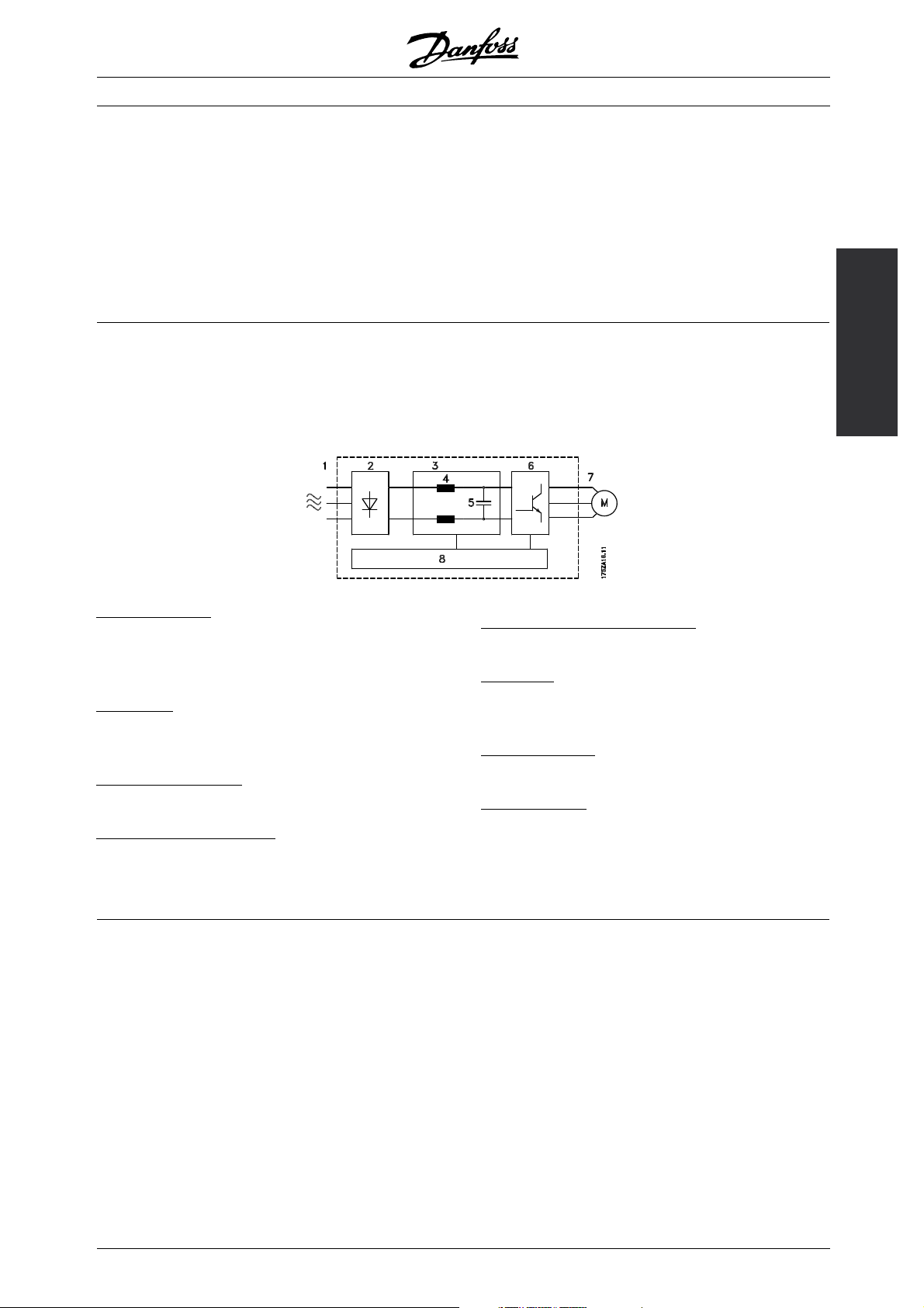
■Control principle
A frequency converter rectifies AC voltage from
mains into DC voltage, after which this DC
voltage is converted into a AC current with a
variable amplitude and frequency.
1. Mains voltage
3 x 200 - 240
3 x 380 - 460 V AC, 50 / 60 Hz.
3 x 525 - 600 V AC, 50 / 60 Hz.
. Rectifier
2
A three-pha
current into DC current.
3
. Intermediate circuit
DC voltage = 1.35 x mains voltage [V].
4
. Intermediate circuit coils
Even out t
the harmonic current feedback to the mains supply.
VAC,50/60Hz.
se rectifier bridge that rectifies AC
he intermediate circuit voltage and reduce
The motor is thus supplied with variable voltage and
frequency, which enables infinitely variable speed
control of three-phased, standard AC motors.
. Intermediate circuit capacitors
5
Even out the intermediate circuit voltage.
6
. Inverter
Converts DC voltage into variable AC voltage
withavariablefrequency.
. Motor voltage
7
Variable AC voltage, 0-100% of mains supply voltage.
8
. Control card
This is where to find the computer that controls
the inverter which generates the pulse pattern by
which the DC voltage is converted into variable
AC voltage with a variable frequency.
HVAC
Introduction to
MG.61.A5.02 - VLT is a registered Danfoss trademark
9
Page 10
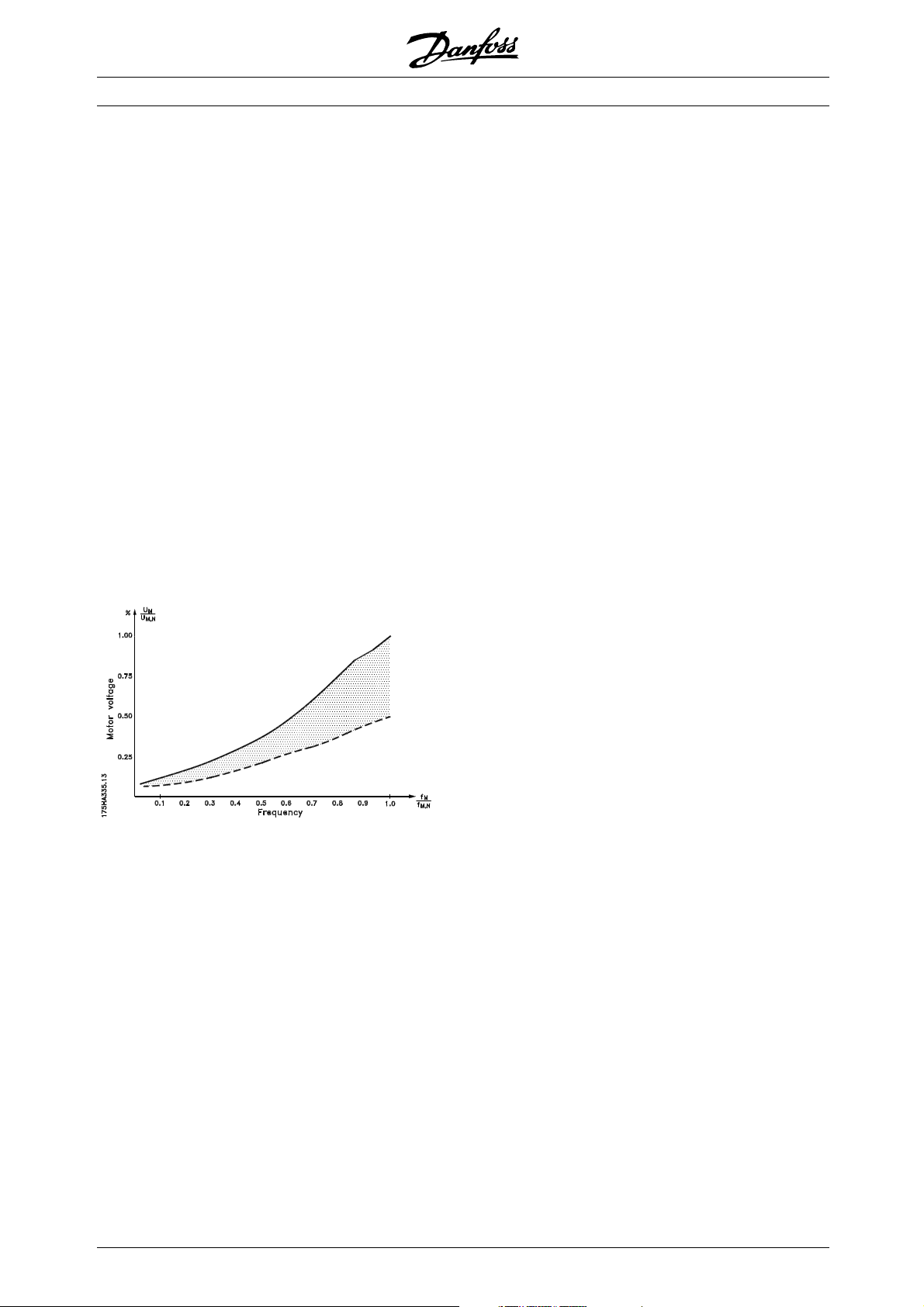
■AEO - Automatic Energy Optimization
Normally, the U/f characteristics have to be set on the
basis of the expected load at different frequencies.
However, knowing the load at a given frequency in an
installation is often a problem. This problem can be
solved by using a VLT 6000 HVAC with its integral
Automatic Energy Optimization (AEO), which ensures
optimum energy utilization. All VLT 6000 HVAC units
feature this function as a factory setting, i.e. it is
not necessary to adjust the frequency converter U/f
ratio in order to obtain maximum energy savings.
In other frequency converters, the given load and
voltage/frequency ratio (U/f) must be assessed to carry
out correct setting of the frequency converter.
Using Automatic Energy Optimization (AEO), you
no longer need to calculate or assess the system
characteristics of the installation, since Danfoss VLT
6000 HVAC units guarantee optimum, load-dependent
energy consumption by the motor at all times.
The figure on the right illustrates the working
range of the AEO function, within which energy
optimization is enabled.
VLT®6000 HVAC Series
If the AEO function has been selected in parameter 101,
Torque characteristics, this function will be constantly
active. If there is a major deviation from the optimum U/f
ratio, the frequency converter will quickly adjust itself.
Advantages of the AEO function
• Automatic energy optimization
• Compensation if an oversize motor is used
• AEO matches operations to daily or
seasonal fluctuations
• Energy savings in a constant air volume system
• Compensation in the oversynchronous
working range
• Reduces acoustic motor noise
10
MG.61.A5.02 - VLT is a registered Danfoss trademark
Page 11
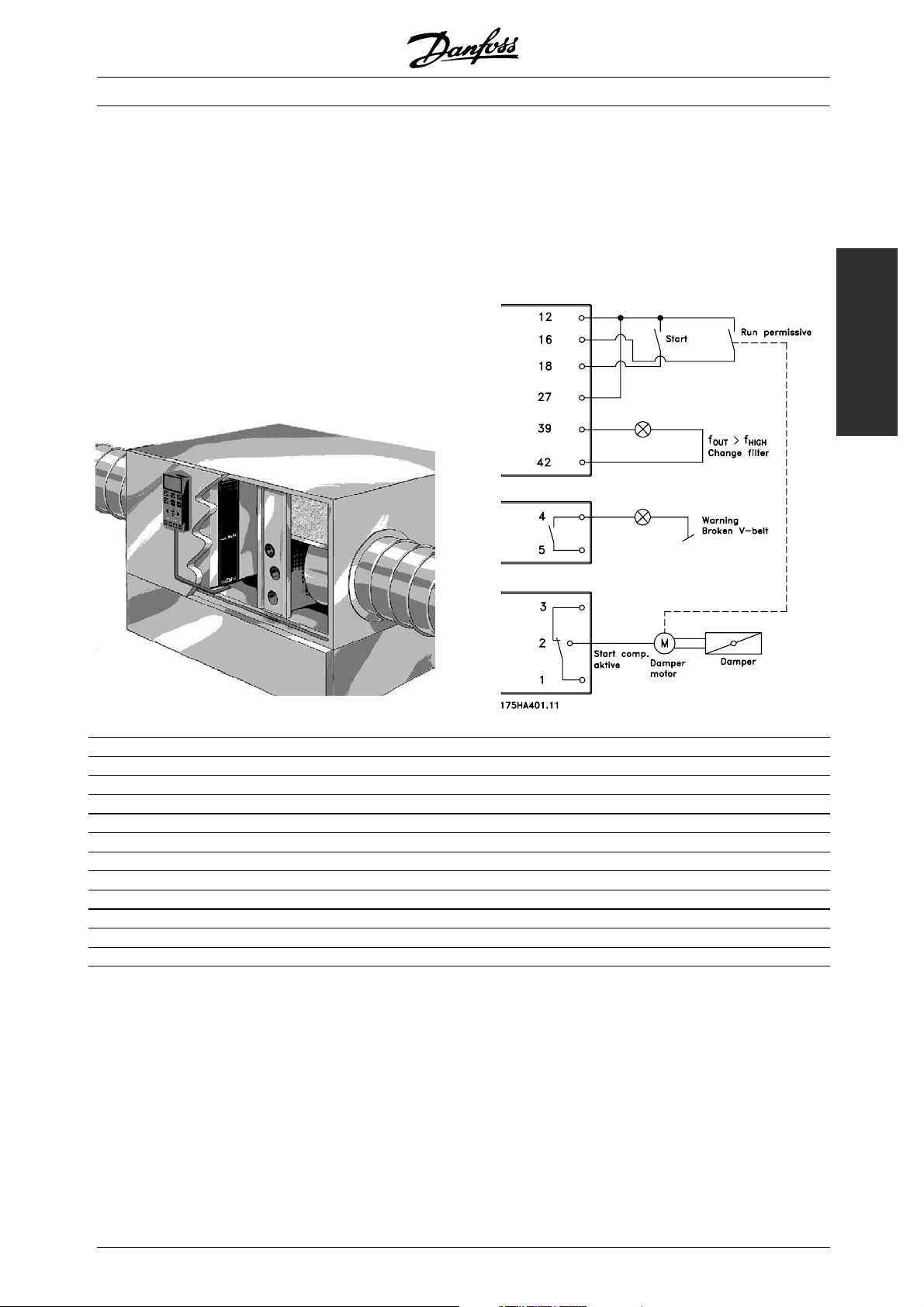
■Example of application - Speed control of
fan in ventilation system
The AHU installation is able to distribute air throughout
the building or to one or several parts of a building.
Normally, an AHU installation consists of a fan and
a motor that supply air, a fan scroll and a duct
system with filters. If centralised air distribution is
applied, the efficiency of the installation will increase
and major energy savings can be made.
A VLT 6000 HVAC enables excellent control and
monitoring, thereby ensuring perfect conditions
in the building at all times.
VLT®6000 HVAC Series
This example shows an application with Run permissive,
warning against no load and warning for filter change.
The Run permissive function ensures that the frequency
converter will not start the motor until the discharge
damper has opened. If the V-belt to the fan breaks
and if the filter is to be changed, this application
will also give a warning on an output.
HVAC
Introduction to
Set the following parameters:
Par. 100 Configuration Open loop [0]
Par. 221 Warning: Low current, I
LOW
Par. 224 Warning: High frequency, f
HIGH
Depends on unit
Par. 300 Terminal 16 Digital inputs Run permissive [8]
Par. 302 Terminal 18 Digital inputs Start [1]
Par. 308 Terminal 53, analogue input voltage Reference [1]
Par. 309 Terminal 53, min. scaling 0 v
Par. 310 Terminal 53, max. scaling 10 v
Par. 319 Output Output frequency greater than f
Par. 323 Relay 1 Start command active [27]
Par. 326 Relay 2 Alarm or warning [12]
Par. 409 Function at no load Warning [1]
HIGH
par. 224
MG.61.A5.02 - VLT is a registered Danfoss trademark
11
Page 12
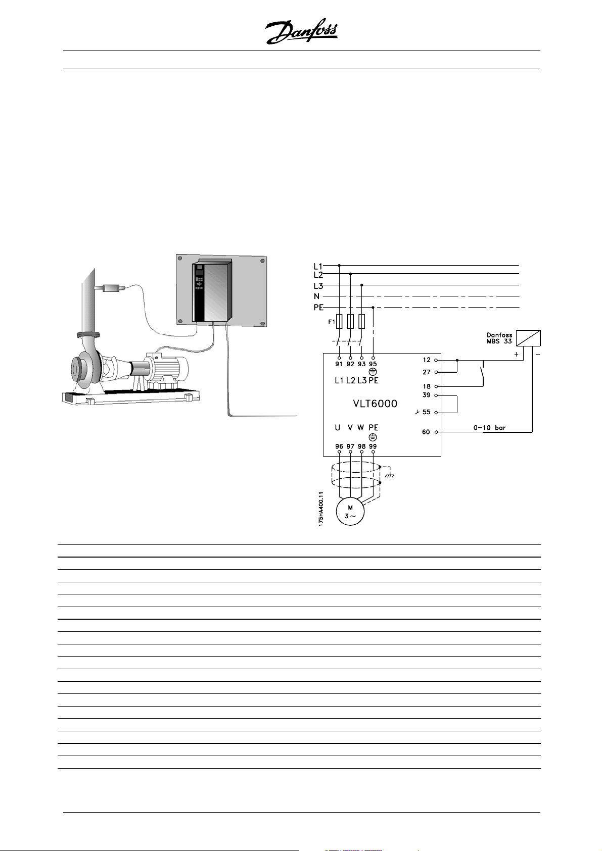
■Example of application - Constant pressure
regulation in water supply system
The demand for water from waterworks varies
considerably during the course of a day. In the night,
practically no water is used, while in the morning
and in the evening the consumption is high. In order
to maintain a suitable pressure in the water supply
lines in relation to the current demand, the water
supply pumps are equipped with speed control.
The use of frequency converters enables the energy
consumed by the pumps to be kept at a minimum,
while optimizing the water supply to consumers.
VLT®6000 HVAC Series
A VLT 6000 HVAC with its integral PID controller
ensures simple and quick installation. For example,
an IP54 unit can be mounted close to the pump on
the wall and the existing line cables can be used as
mains supply to the frequency converter. A Pressure
transmitter (e.g. Danfoss MBS 33 0-10) bar can
be fitted a couples of metres from the joint outlet
point from the waterworks to obtain closed loop
regulation. Danfoss MBS 33 is a two-wire transmitter
(4-20 mA) that can be powered directly from a VLT
6000 HVAC. The required setpoint (e.g. 5 bar) can
be set locally in parameter 418 Setpoint 1.
Set the following parameters:
Par. 100 Configuration Closed loop [1]
Par. 205 Maximum reference 10 bar
Par. 302 Terminal 18 Digital inputs Start [1]
Par. 314 Terminal 60, analog input current Feedback signal [2]
Par. 315 Terminal 60, min. scaling 4 mA
Par. 316 Terminal 60, max. scaling 20 mA
Par. 403 Sleep mode timer 10 sec.
Par. 404 Sleep frequency 15 Hz
Par. 405 Wake-up frequency 20 Hz
Par. 406 Boost setpoint 125%
Par. 413 Minimum feedback 0
Par. 414 Maximum feedback 10 bar
Par. 415 Process units Bar [16]
Par. 418 Setpoint 1 5 bar
Par. 420 PID normal/inverse control Normal
Par. 423 PID proportional gain 0.5-1.0
Par. 424 PID integration time 3-10
Par. 427 PID low pass filter 0.5-1.5
12
MG.61.A5.02 - VLT is a registered Danfoss trademark
Page 13

VLT®6000 HVAC Series
■Fire mode
NB!:
Please note the frequency converter is
only one component of the HVAC system.
Correct function of Fire Mode depends on the
correct design and selection of system components.
Ventilation systems working in life safety applications
have to be approved by the local fire Authorities.
Non-interruption of the frequency converter
due to Fire Mode operation may cause over
pressure and result in damage to HVAC system
and components, including dampers and air
ducts. The frequency converter itself may be
damaged and it may cause damage or fire.
Danfoss A/S accepts no responsibility for errors,
malfunctions personal injur y or any damage to
the frequency converter itself or components
herein, HVAC systems and components herein or
other property when the frequency converter has
been programmed forFire Mode. In no event shall
Danfossbe liable to the end u ser orany other party
for any direct or indirect, special or consequential
damage or loss suffered by such party, which has
occurred due to the frequency converter being
programmed and operated in Fire Mode
To be able to use Fire Mode please also note that
input 27 must be "high" and no coast bit present via
fieldbus. To ensure that no coast can interrupt Fire
Mode via fieldbus please select Digital Input [0] in par.
503. Then coasting via fieldbus disabled.
HVAC
Introduction to
TheFireModefunctionismadetoensuretheVLT
6000 can run without interruption. This means most
alarms and warnings will not cause a trip and trip
lock is disabled. This is useful in case of fire or other
emergencies. Until the motor wires or the frequency
converter itself are destroyed every attempt is made
to keep running. A warning will flash when these
limits have been exceeded. If the warning still flashes
after a power cycle please contact your local Danfoss
supplier. In the following is a table to show the alarms
and when the frequency converter changes state
depending on selection in parameter 430. Trip and
lock ([0] in parameter 430) are valid in normal operation
mode.FireModetripandreset([1]or[2]inparameter
430) means that a reset is automatically performed
without the need of manual resetting. Go to Fire
Mode bypass ([3] in parameter 430) is valid in case
one of the mentioned alarms causes a trip. After the
in parameter 432 selected time delay has passed an
output is set. This output is programmed in parameter
319, 321, 323 or 326. If a relay option is fitted it can
also be selected in parameter 700, 703, 706 or 709.
In parameter 300 and 301 it can be selected if the
logic, for the Fire Mode activation, shall be active high
or low. Please note parameter 430 must be different
to[0]fortheFireModetobeenabled.
MG.61.A5.02 - VLT is a registered Danfoss trademark
13
Page 14
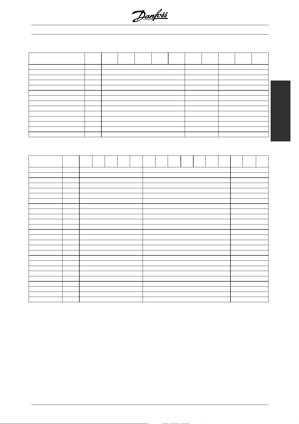
VLT®6000 HVAC Series
No. Description TRIP
[0]
2 Live zero fault
(LIVE ZERO ERROR)
4 Mains imbalance
(MAINS IMBALANCE)
7 Overvoltage
(DC LINK OVERVOLT)
8 Undervoltage
(DC LINK UNDERVOLT)
9 Inverter overloaded
(INVERTER TIME)
10 Motor overloaded
(MOTOR TIME)
11 Motor thermistor(MOTOR
THERMISTOR)
12 Current limit
(CURRENT LIMIT)
13 Overcurrent
(OVERCURRENT)
14 Earth fault
(EARTH FAULT)
15 Switch mode fault
(SWITCH MODE FAULT)
16 Short-circuit
(CURR.SHORT CIRCUIT)
17 Serial communication timeout
(STD BUSTIMEOUT)
18 HPFB bus timeout
(HPFB TIMEOUT)
22 Auto-optimation fault
(AMA FAULT)
29 Heat-sink temperature too
high
(HEAT SINK OVERTEMP.)
30 Motor phase U missing
(MISSING MOT.PHASE U)
31 Motor phase V missing
(MISSING MOT.PHASE V)
32 Motor phase W missing
(MISSING MOT.PHASE W)
34 HPFB communication fault
(HPFB TIMEOUT)
37 Inverter fault (GATE DRIVE
FAULT)
60 Safety stop
(EXTERNAL FAULT)
63 Output current low
(I MOTOR < I LOW)
80 Fire mode was active
(FIREMODEWASACTIVE)
99 Unknown fault
(UNKNOWN FAULT)
X
x x x
x
x
x
x
x
x
x x x x
x x x x
x x x x
x x x x
x
x
x
x x x
x
x
x
x
x x x x
x
x
x
x x
LOCK
[0]
FIRE MODE
Trip & reset
[1], [2]
Go to
FIRE MODE
BYPASS [3]
14
MG.61.A5.02 - VLT is a registered Danfoss trademark
Page 15
VLT®6000 HVAC Series
■CE labelling
What is CE labelling?
The purpose of CE labelling is to avoid technical
obstacles to trade within EFTA and the EU. The
EU has introduced the CE label as a simple way of
showing whether a product complies with the relevant
EU directives. The CE label says nothing about the
specifications or quality of the product. Frequency
converters are regulated by three EU directives:
The machinery directive (98/37/EEC)
All machines with critical moving parts are covered
by the machinery directive, which came into force
on 1 January 1995. Since a frequency converter is
largely electrical, it does not fall under the machinery
directive. However, if a frequency converter is supplied
for use in a machine, we provide information on safety
aspects relating to the frequency converter. We do
this by means of a manufacturer’sdeclaration.
The low-voltage directive (73/23/EEC)
Frequency converters must be CE labelled in
accordance with the low-voltage directive, which came
into force on 1 January 1997. The directive applies to
all electrical equipment and appliances used in the 50 1000 Volt AC and the 75 - 1500 Volt DC voltage ranges.
Danfoss CE labels in accordance with the directive and
issues a declaration of conformity upon request.
The EMC directive (89/336/EEC)
EMC is short for electromagnetic compatibility. The
presence of electromagnetic compatibility means
that the mutual interference between different
components/appliances is so small that the functioning
of the appliances is not affected.
The EMC directive came into force on 1 January 1996.
Danfoss CE labels in accordance with the directive and
issues a declaration of conformity upon request. In
order that EMC-correct installation can be carried out,
this manual gives detailed instructions for installation. In
addition, we specify the standards which our different
products comply with. We offer the filters that can be
seen from the specifications and provide other types of
assistance to ensure the optimum EMC result.
In the great majority of cases, the frequency converter
is used by professionals of the trade as a complex
component forming part of a larger appliance, system
orinstallation. Itmustbenotedthattheresponsibility
for the final EMC properties of the appliance, system
or installation rests with the installer.
NOTE: VLT 6001-6072, 525-600 V are not CE labelled.
HVAC
Introduction to
■PC software and serial communication
Danfoss offers various options for serial communication.
Using serial communication, it is possible to monitor,
program and control one or several frequency
converters from a centrally located computer.
All VLT 6000 HVAC units have a RS 485 port as
standard with a choice of four protocols. The protocols
selectable in parameter 500 Protocols are:
• FC protocol
• Johnson Controls Metasys N2
• Landis/Staefa Apogee FLN
• Modbus RTU
A bus option card allows higher transmission speed
than RS 485. In addition, a higher number of units
can be linked to the bus and alternative transmission
media can be used. Danfoss offers the following
option cards for communication:
• Profibus
• LonWorks
• DeviceNet
Information on the installation of various options
is not included in this manual.
available for this purpose. It can be used to monitor,
program and control one or several VLT 6000 HVAC
units. For further information, see the Design Guide
for VLT 6000 HVAC or contact Danfoss.
500-566 Serial communication
NB!:
Information on the use of RS-485 serial
interface is not included i
further information, see the Design Guide for
VLT 6000 HVAC or contact Danfoss.
n this manual. For
Using the RS 485 port enables communication, e.g.
TM
with a PC. A Windows
MG.61.A5.02 - VLT is a registered Danfoss trademark
program, called MCT 10,is
15
Page 16

VLT®6000 HVAC Series
■Unpacking and ordering a VLT frequency c onverter
If you are in doubt as to which frequency converter
you have received and which options it contains,
use the following to find out.
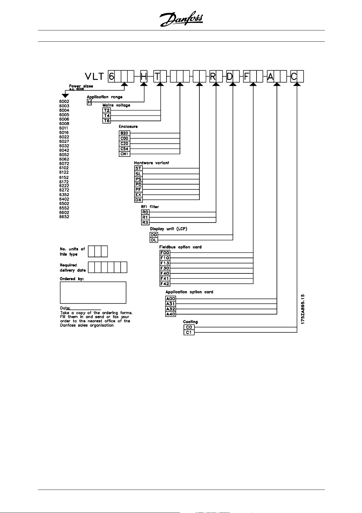
■Type code ordering number string
On the basis of your order, the frequency converter is
given an ordering number that can be seen from the
nameplate on the unit. The number may look as follows:
VLT-6008-H-T4-B20-R3-DL-F10-A00-C0
This means that the frequency converter ordered is a
VLT 6008 for three-phase mains voltage of 380-460 V
(T4) in Bookstyle enclosure IP 20 (B20). The hardware
variant is with integral RFI filter, classes A & B (R3). The
frequency converter features a control unit (DL)witha
PROFIBUS option card (F10). No option card (A00)
and no conformal coating (C0) Character no. 8 ( H)
indicates the application range of the unit: H =HVAC.
IP 00: This enclosure is only available for the larger
power sizes of the VLT 6000 HVAC series. It is
recommended for installation in standard cabinets.
IP 20 Bookstyle: This enclosure is designed for
cabinet installation. It takes up a minimum of
space and can be fitted side-by-side without
installation of extra cooling equipment.
IP 20/NEMA 1: This enclosure is used as standard
enclosure for VLT 6000 HVAC. It is ideal for
cabinet installation in areas where a high degree
of protection is required. This enclose also
permits side-by-side installation.
IP 54: This enclosure can be fitted direct to the
wall. Cabinets are not required. IP 54 units can
also be installed side-by-side.
Hardware variant
The units in the programme are available in the
following hardware variants:
ST: Standard unit with or without control unit.
WithoutDCterminals,exceptfor
VLT 6042-6062, 200-240 V
VLT 6016-6072, 525-600 V
SL: Standard unit with DC terminals.
EX: Extended unit with control unit, DC terminals,
connection of external 24 V DC supply for
back-up of control PCB.
DX: Extended unit with control unit, DC terminals,
built-in mains fuses and disconnector,
connection of external 24 V DC supply for
back-up of control PCB.
PF: Standard unit with 24 V DC supply for back-up
of control PCB and built-in main fuses. No DC
terminals.
PS: Standard unit with 24 V DC supply for back-up
of control PCB. No DC terminals.
PD: Standard unit with 24 V DC supply for back-up
of control PCB, built-in main fuses and
disconnect. No DC terminals.
RFI filter
Bookstyle units always come with an integral RFI
filter that complies with EN 55011-B with 20 m
screened/armoured motor cable and EN 55011-A1
with 150 m screened/armoured motor cable. Units
for mains voltage of 240 V and a motor power of up
to and including 3.0 kW (VLT 6005) and units for a
mains voltage of 380-460 V and a motor power of
up to 7.5 kW (VLT 6011) are always supplied with an
integral class A1 & B filter. Units for higher motor
power than these (3.0 and 7.5 kW, respectively) can
be ordered either with or without an RFI filter.
16
Control unit (keypad and display)
All types of units in the programme, except for
IP21 VLT 6402-6602, 380-460 V, VLT 6502-6652,
525-600 V and IP 54 units, can be ordered either
with or without the control unit. IP 54 units always
come with a control unit. All types of units in the
programme are available with built-in application
options including a relay card with four relays or a
cascade controller card.
Conformal Coating
All types of units in the programme are available with
or without conformal coating of the PCB.
VLT 6402-6602, 380-460 V and VLT 6102-6652,
525-600 V are only available coated.
MG.61.A5.02 - VLT is a registered Danfoss trademark
Page 17
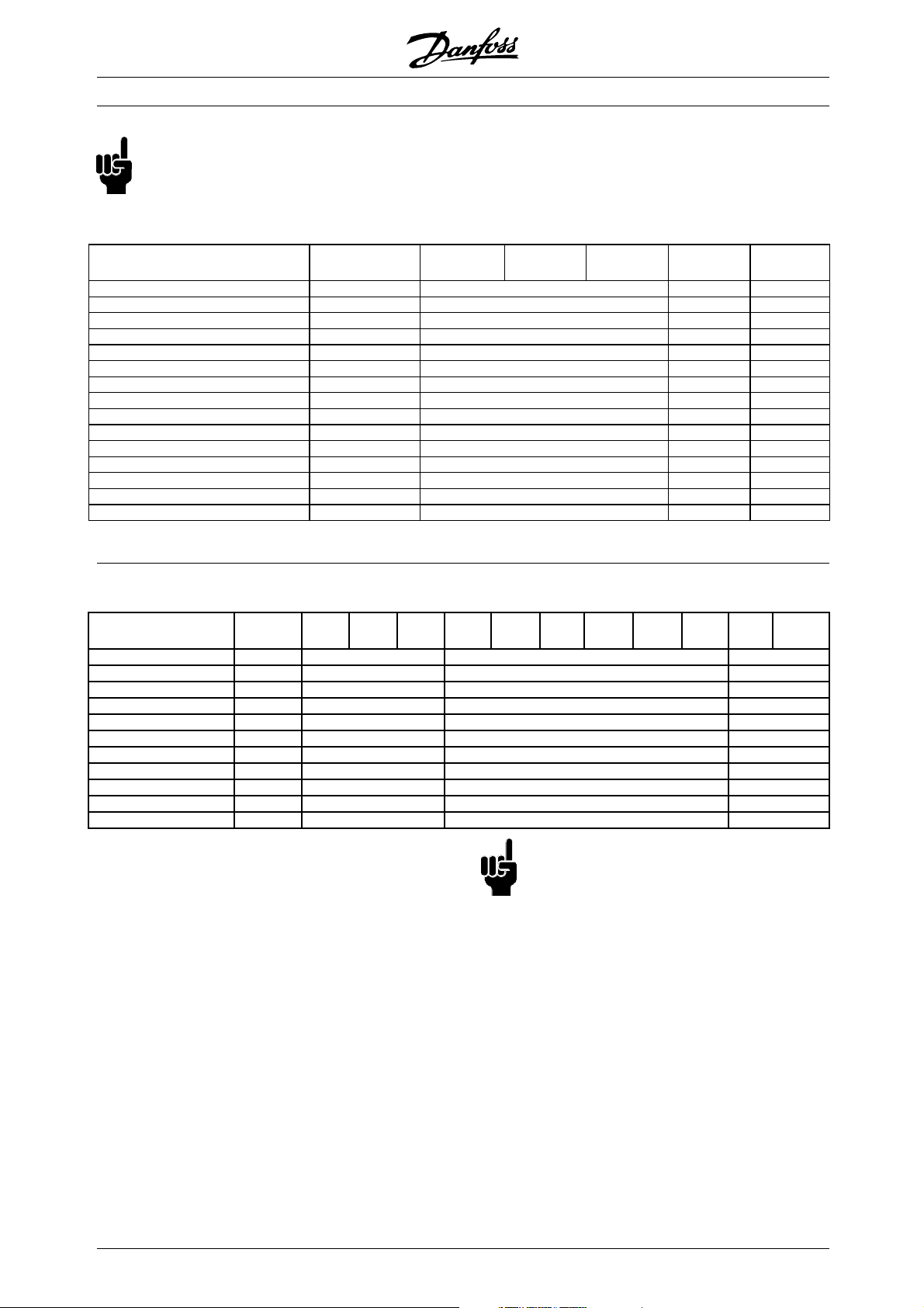
200-240 V
VLT®6000 HVAC Series
Typecode
Position in string
T2
9-10
C00
11-13
B20
11-13
C20
11-13
CN1
11-13
C54
11-13ST14-15SL14-15R016-17R116-17R316-17
1.1 kW/1.5 HP 6002 XX XX X
1.5 kW/2.0 HP 6003 XX XX X
2.2 kW/3.0 HP 6004 XX XX X
3.0 kW/4.0 HP 6005 XX XX X
4.0 kW/5.0 HP 6006 XXXXXX
5.5 kW/7.5 HP 6008 XXXXXX
7.5 kW/10 HP 6011 XXXXXX
11 kW/15 HP 6016 XXXXXX
15 kW/20 HP 6022 XXXXXX
18.5 kW/25 HP 6027 XXXXXX
22 kW/30 HP 6032 XXXXXX
30 kW/40 HP 6042 XXXX XX
HVAC
Introduction to
37 kW/50 HP 6052 XXXX XX
45 kW/60 HP 6062 XXXX XX
380-460 V
Typecode
Position in stringT49-10
1.1 kW/1.5 HP 6002 XX XX X
1.5 kW/2.0 HP 6003 XX XX X
2.2 kW/3.0 HP 6004 XX XX X
3.0 kW/4.0 HP 6005 XX XX X
4.0 kW/5.0 HP 6006 XX XX X
5.5 kW/7.5 HP 6008 XX XX X
7.5 kW/10 HP 6011 XX XX X
11 kW/15 HP 6016 XXXX XX
15 kW/20 HP 6022 XXXX XX
18.5 kW/25 HP 6027 XXXX XX
22 kW/30 HP 6032 XXXX XX
30 kW/40 HP 6042 XXXX XX
37 kW/50 HP 6052 XXXX XX
45 kW/60 HP 6062 XXXX XX
55 kW/75 HP 6072 XXXX XX
75 kW/100 HP 6102 XXXX XX
90 kW/125 HP 6122 XXXX XX
110 kW/150 HP 6152 XXXX XXXXXXX
132 kW/200 HP 6172 XXXX XXXXXXX
160 kW/250 HP 6222 XXXX XXXXXXX
200 kW/300 HP 6272 XXXX XXXXXXX
250 kW/350 HP 6352 XXXX XXXXXXX
315 kW/450 HP 6402 XXXX XXXXXXX
355 kW/500 HP 6502 XXXX XXXXXXX
400 kW/550 HP 6552 XXXX XXXXXXX
450 kW/600 HP 6602 XXXX XXXXXXX
C00
11-13
B20
11-13
C20
11-13
CN1
C54
11-13
11-13ST14-15SL14-15EX14-15DX14-15PS14-15PD14-15PF14-15R016-17R116-17R316-17
Voltage
T2: 200-240 VAC
T4: 380-460 VAC
Enclosure
C00: Compact IP 00
B20: Bookstyle IP 20
C20: Compact IP 20
CN1: Compact NEMA 1
C54: Compact IP 54
Hardware variant
ST: Standard
SL: Standard with DC terminals
EX: Extended with 24 V supply and DC terminals
DX: Extended with 24 V supply, DC terminals,
disconnect and fuse
MG.61.A5.02 - VLT is a registered Danfoss trademark
PS: Standard with 24 V supply
PD: Standard with 24 V supply, fuse and disconnect
PF: Standard with 24 V supply and fuse
RFI filter
R0: Without filter
R1: Class A1 filter
R3: Class A1 and B filter
17
Page 18
NB!:
NEMA 1 exceeds IP 20
525-600 V
VLT®6000 HVAC Series
Typecode
Position in string
T6
9-10
C00
11-13
C20
11-13
CN1
11-13
ST
14-15
R0
16-17
1.1 kW/1.5 HP 6002 XXX X
1.5 kW/2.0 HP 6003 XXX X
2.2 kW/3.0 HP 6004 XXX X
3.0 kW/4.0 HP 6005 XXX X
4.0 kW/5.0 HP 6006 XXX X
5.5 kW/7.5 HP 6008 XXX X
7.5 kW/10 HP 6011 XXX X
11 kW/15 HP 6016 X X X
15 kW/20 HP 6022 X X X
18.5 kW/25 HP 6027 X X X
22 kW/30 HP 6032 X X X
30 kW/40 HP 6042 X X X
37 kW/50 HP 6052 X X X
45 kW/60 HP 6062 X X X
55 kW/75 HP 6072 X X X
VLT 6102-6652, 525-600 V
Typecode
Position in string
75 kW / 100 HP 6102 XXXXXXX XXXX
90 kW / 125 HP 6122 XXXXXXX XXXX
110 kW / 150 HP 6152 XXXXXXX XXXX
132 kW / 200 HP 6172 XXXXXXX XXXX
160 kW / 250 HP 6222 XXXXXXX XXXX
200 kW / 300 HP 6272 XXXXXXX XXXX
250 kW / 350 HP 6352 XXXXXXX XXXX
315 kW / 400 HP 6402 XXXXXXX XXXX
400 kW / 500 HP 6502 XXXXXXX XXX
450 kW / 600 HP 6602 XXXXXXX XXX
500 kW / 650 HP 6652 XXXXXXX XXX
T6
9-10
C00
11-13
CN1
11-13
C54
11-13ST14-15EX14-15DX14-15PS14-15PD14-15PF14-15R016-17R116-17
1)
1) R1 is not available with DX, PF, PD options. NB!:
NEMA 1 exceeds
IP 20
Voltage
T6: 525-6
Enclosure
C00: Compact IP 00
C20: Compac
CN1: Compact NEMA 1
C54: Compact IP 54
00 VAC
tIP20
18
Hardware variant
ard
ST: Stand
EX: Extended with 24 V supply and DC terminals
DX: Extended with 24 V supply, DC terminals,
ct and fuse
disconne
PS: Standard with 24 V supply
MG.61.A5.02 - VLT is a registered Danfoss trademark
PD: Standard with 24 V supply, fuse and disconnect
ard with 24 V supply and fuse
PF: Stand
RFI filter
R0: Without filter
R1: Class A1
filter
Page 19
Optional selections, 200-600 V
Display Position: 18-19
D01)Without LCP
DL With LCP
Fieldbus option Position: 20-22
F00 No options
F10 Profibus DP V1
F13 Profibus FMS
F30 DeviceNet
F40 LonWorks free topology
F41 LonWorks 78 kBps
F42 LonWorks 1.25 MBps
Application option Position: 23-25
A00 No options
A312)Relay card 4 relays
A32 Cascade Controller
A40 Real Time Clock
Coating Position: 26-27
C03)No coating
C1 With coating
1) Not available with enclosure compact IP 54
2) Not available with fieldbus options (Fxx)
3) Not available for power sizes from 6402 to 6602, 380-460 V and
6102-6652, 525-600 V
VLT®6000 HVAC Series
HVAC
Introduction to
MG.61.A5.02 - VLT is a registered Danfoss trademark
19
Page 20
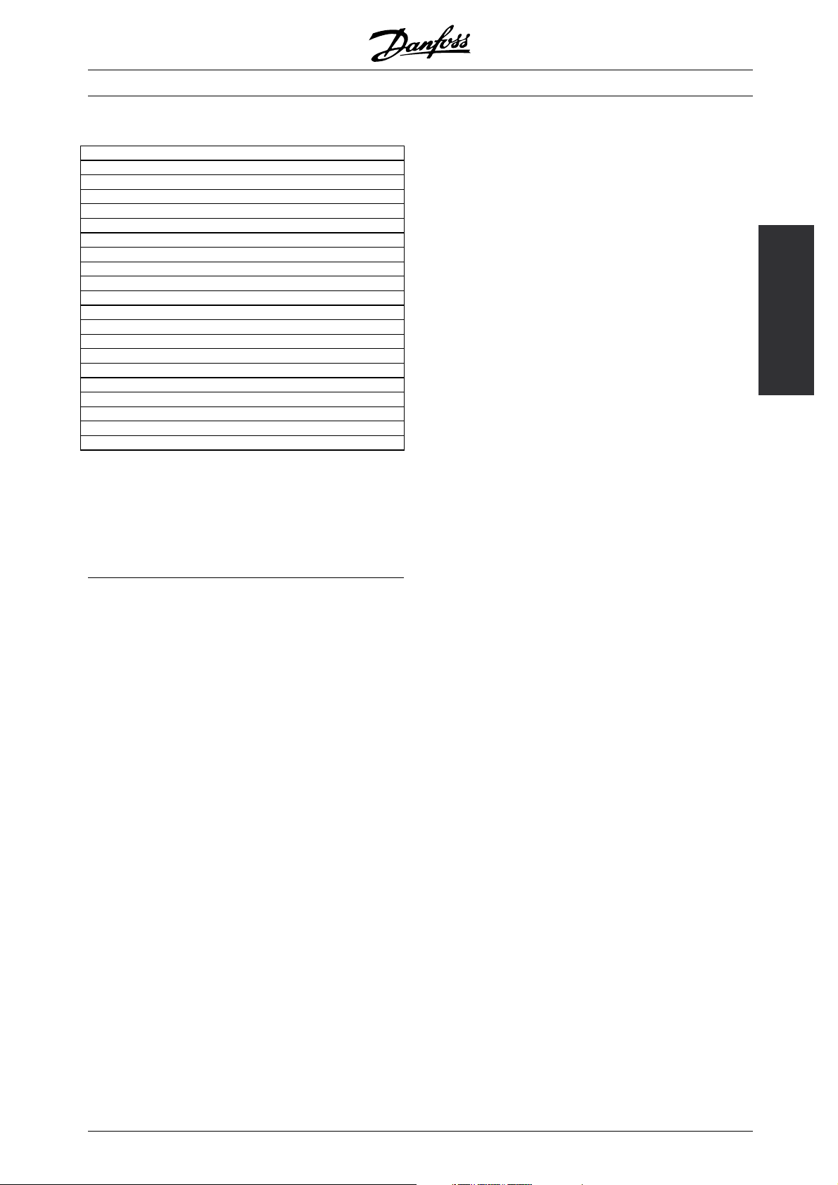
■Ordering form
VLT®6000 HVAC Series
20
MG.61.A5.02 - VLT is a registered Danfoss trademark
Page 21

VLT®6000 HVAC Series
■Mains supply (L1, L2, L3)
Mains supply (L1, L2, L3):
Supply voltage 200-240 V units ........................................................................ 3 x 200/208/220/230/240 V ±10%
Supply voltage 380-460 V units ........................................................................ 3 x 380/400/415/440/460 V ±10%
Supply voltage 525-600 V units ............................................................................... 3 x 525/550/575/600 V ±10%
Supply frequency ............................................................................................................................ 48-62 Hz ± 1%
Max. imbalance of supply voltage:
VLT 6002-6011, 380-460 V and 525-600 V and VLT 6002-6005, 200-240 V .......... ±2.0% of rated supply voltage
VLT 6016-6072, 380-460 V and 525-600 V and VLT 6006-6032, 200-240 V .......... ±1.5% of rated supply voltage
VLT 6102-6602, 380-460 V and VLT 6042-6062, 200-240 V .................................. ±3.0% of rated supply voltage
VLT 6102-6652, 525-600 V ....................................................................................... ±3% of rated supply voltage
True Power factor (λ) ...................................................................................................... 0.90 nominal at rated load
Displacement Power Factor (cos. ϕ) ............................................................................................ near unity (>0.98)
No. of switches on supply input L1, L2, L3 .......................................................................... approx. 1 time/2 min.
Max. short-circuit current ....................................................................................................................... 100.000 A
VLT output data (U, V, W):
Output voltage ................................................................................................................ 0-100% of supply voltage
Output frequency:
Output frequency 6002-6032, 200-240V .............................................................................. 0-120 Hz, 0-1000 Hz
Output frequency 6042-6062, 200-240V ................................................................................ 0-120 Hz, 0-450 Hz
Output frequency 6002-6062, 380-460V .............................................................................. 0-120 Hz, 0-1000 Hz
Output frequency 6072-6602, 380-460V ................................................................................ 0-120 Hz, 0-450 Hz
Output frequency 6002-6016, 525-600V .............................................................................. 0-120 Hz, 0-1000 Hz
Output frequency 6022-6062, 525-600V ................................................................................ 0-120 Hz, 0-450 Hz
Output frequency 6072, 525-600V ......................................................................................... 0-120 Hz, 0-450 Hz
Output frequency 6102-6352, 525-600V ................................................................................ 0-132 Hz, 0-200 Hz
Output frequency 6402-6652, 525-600V ................................................................................ 0-132 Hz, 0-150 Hz
Rated motor voltage, 200-240 V units .............................................................................. 200/208/220/230/240V
Rated motor voltage, 380-460 V units .............................................................................. 380/400/415/440/460V
Rated motor voltage, 525-600 V units ............................................................................................ 525/550/575 V
Rated motor frequency ............................................................................................................................ 50/60 Hz
Switching on output ................................................................................................................................. Unlimited
Ramp times ....................................................................................................................................... 1 - 3600 sec.
Installation
Torque characteristics:
Starting torque ............................................................................................................................... 110% for 1 min.
Starting torque (parameter 110 High break-away torque) ....................................... Max. torque: 160% for 0.5 sec.
Acceleration torque ....................................................................................................................................... 100%
Overload torque ............................................................................................................................................ 110%
MG.61.A5.02 - VLT is a registered Danfoss trademark
21
Page 22

VLT®6000 HVAC Series
Control card, digital inputs:
Number of programmable digital inputs ................................................................................................................ 8
Terminal nos. ............................................................................................................ 16, 17, 18, 19, 27, 29, 32, 33
Voltage level ........................................................................................................... 0-24 V DC (PNP positive logics)
Voltage level, logical ’0’ ............................................................................................................................ < 5 V DC
Voltage level, logical ’1’ ........................................................................................................................... >10 V DC
Maximum voltage on input ........................................................................................................................ 28 V DC
Input resistance, R
Scanning time per input ............................................................................................................................. 3 msec.
Reliable galvanic isolation: All digital inputs are galvanically isolated from the supply voltage (PELV). In
addition, the digital inputs can be isolated from the other terminals on the control card by connecting
an external 24 V DC supply and opening switch 4. See Switches 1-4.
Control card, analogue inputs
No. of programmable analogue voltage inputs/thermistor inputs .......................................................................... 2
Terminal nos. ................................................................................................................................................ 53, 54
Voltage level .......................................................................................................................... 0 - 10 V DC (scalable)
Input resistance, R
No. of programmable analogue current inputs ..................................................................................................... 1
Terminal no ground. ............................................................................................................................................ 55
Current range ...................................................................................................................... 0/4 - 20 mA (scalable)
Input resistance, R
Resolution .......................................................................................................................................... 10 bit + sign
Accuracy on input .......................................................................................................... Max. error 1% of full scale
Scanning time per input ............................................................................................................................. 3 msec.
Reliable galvanic isolation: All analogue inputs are galvanically isolated from the supply
voltage (PELV) and other high-voltage terminals.
............................................................................................................................................ 2 k
i
............................................................................................................................. approx. 10 k
i
........................................................................................................................................... 200
i
Control card, pulse input:
No. of programmable pulse inputs ........................................................................................................................ 3
Terminal nos. .......................................................................................................................................... 17, 29, 33
Max. frequency on terminal 17 ...................................................................................................................... 5 kHz
Max. frequency on terminals 29, 33 ............................................................................ 20 kHz (PNP open collector)
Max. frequency on terminals 29, 33 ........................................................................................... 65 kHz (Push-pull)
Voltage level ........................................................................................................... 0-24 V DC (PNP positive logics)
Voltage level, logical ’0’ ............................................................................................................................ < 5 V DC
Voltage level, logical ’1’ ........................................................................................................................... >10 V DC
Maximum voltage on input ........................................................................................................................ 28 V DC
Input resistance, R
............................................................................................................................................ 2 k
i
Scanning time per input ............................................................................................................................. 3 msec.
Resolution .......................................................................................................................................... 10 bit + sign
Accuracy (100-1 kHz), terminals 17, 29, 33 ............................................................... Max. error: 0.5% of full scale
Accuracy (1-5 kHz), terminal 17 ................................................................................. Max. error: 0.1% of full scale
Accuracy (1-65 kHz), terminals 29, 33 ....................................................................... Max. error: 0.1% of full scale
Reliable galvanic isolation: All pulse inputs are galvanically isolated from the supply voltage (PELV). In
addition, pulse inputs can be isolated from the other terminals on the control card by connecting an
external 24 V DC supply and opening switch 4. See Switches 1-4.
Control card, digital/pulse and analogue outputs:
No. of programmable digital and analogue outputs .............................................................................................. 2
Terminal nos. ................................................................................................................................................ 42, 45
Voltage level at digital/pulse output ...................................................................................................... 0 - 24 V DC
Minimum load to ground (terminal 39) at digital/pulse output ............................................................................ 600
Frequency ranges (digital output used as pulse output) ............................................................................ 0-32 kHz
22
MG.61.A5.02 - VLT is a registered Danfoss trademark
Page 23

VLT®6000 HVAC Series
Current range at analogue output ........................................................................................................ 0/4 - 20 mA
Maximum load to ground (terminal 39) at analogue output ................................................................................ 500
Accuracy of analogue output ..................................................................................... Max. error: 1.5% of full scale
Resolution on analogue output. ....................................................................................................................... 8 bit
Reliable galvanic isolation: All digital and analogue outputs are galvanically isolated from the
supply voltage (PELV) and other high-voltage terminals.
Control card, 24 V DC supply:
Terminal nos. ................................................................................................................................................ 12, 13
Max. load .................................................................................................................................................. 200 mA
Terminal nos. ground .................................................................................................................................... 20, 39
Reliable galvanic isolation: The 24 V DC supply is galvanically isolated from the supply voltage
(PELV), but has the same potential as the analogue outputs.
Control card, RS 485 serial communication:
Terminal nos. .............................................................................................................. 68 (TX+, RX+), 69 (TX-, RX-)
Reliable galvanic isolation: Full galvanic isolation (PELV).
Relay outputs:
1)
No. of programmable relay outputs ...................................................................................................................... 2
Terminal nos., control card (resistive load only) ....................................................................................... 4-5 (make)
Max. terminal load (AC1) on 4-5, control card ........................................................................ 50 V AC, 1 A, 50 VA
Max. terminal load (DC1 (IEC 947)) on 4-5, control card ................................. 25 V DC, 2 A / 50 V DC, 1 A, 50 W
Max. terminal load (DC1) on 4-5, control card for UL/cUL applications .................... 30 V AC, 1 A / 42.5 V DC, 1A
Terminal nos., power card (resistive and inductive load) ...................................................... 1-3 (break), 1-2 (make)
Max. terminal load (AC1) on 1-3, 1-2, power card ............................................................. 250 V AC, 2 A, 500 VA
Max. terminal load (DC1 (IEC 947)) on 1-3, 1-2, power card ............................. 25 V DC, 2 A / 50 V DC, 1A, 50 W
Min. terminal load (AC/DC) on 1-3, 1-2, power card ....................................... 24 V DC, 10 mA / 24 V AC, 100 mA
1) Rated values for up to 300,000 operations.
At inductive loads the number of operations are reduced by 50%, alternatively the current can be reduced by
50%, thus the 300,000 operations are maintained.
External 24 Volt DC supply (only available with V
LT 6152-6602, 380-460 V):
Terminal nos. ................................................................................................................................................ 35, 36
Voltage range ....................................................................................... 24 V DC ±15% (max. 37 V DC for 10 sec.)
Max. voltage ripple ..................................................................................................................................... 2 V DC
Power consumption .............................................................................. 15 W - 50 W (50 W for start-up, 20 m
sec.)
Min. pre-fuse ............................................................................................................................................... 6 Amp
Reliable galvanic isolation: Full galvanic isolation if the external 24 V DC supply is also of the PELV type.
Installation
Cable lengths and cross-sections:
Max. motor cable length, screened cable ..................................................................................................... 150 m
Max. motor cable length, unscreened cable ................................................................................................. 300 m
Max. motor cable length, screened cable VLT 6011 380-460 V .................................................................... 100 m
Max. motor cable length, screened cable VLT 6011 525-600 V ...................................................................... 50 m
Max. DC-bus cable length, screened cable ........................................... 25 m fro
m frequency converter to DC bar.
Max. cable cross-section to motor, see next section
2
Max. cross-section for 24 V external DC supply ........................................................................ 2.5 mm
Max. cross-section for control cables ....................................................................................... 1.5 mm
Max. cross-section for serial communication ............................................................................ 1.5 mm
/12 AWG
2
/16 A
2
/16 AWG
WG
If UL/cUL is to be complied with, copper cable withtemperatureclass60/75°Cmustbeused
MG.61.A5.02 - VLT is a registered Danfoss trademark
23
Page 24

VLT®6000 HVAC Series
(VLT 6002 - 6072 380 - 460 V, 525-600 V and VLT 6002 - 6032 200 - 240 V).
If UL/cUL is to be complied with, copper cable with temperature class 75°C must be used
(VLT 6042 - 6062 200 - 240 V, VLT 6102 - 6602 380 - 460 V, VLT 6102 - 6652 525 - 600 V).
Connectors are for use of both copper and aluminium cables, unless other is specified.
Control characteristics:
Frequency range .................................................................................................................................. 0 - 1000 Hz
Resolution on output frequency ............................................................................................................. ±0.003 Hz
System response time ............................................................................................................................... 3 msec.
Speed, control range (open loop) ..................................................................................... 1:100 of synchro. speed
Speed, accuracy (open loop) ............................................................................ < 1500 rpm: max. error ± 7.5 rpm
>1500 rpm: max. error of 0.5% of actual speed
Process, accuracy (closed loop) ....................................................................... < 1500 rpm: max. error ± 1.5 rpm
>1500 rpm: max. error of 0.1% of actual speed
All control characteristics are based on a 4-pole asynchronous motor
Accuracy of display readout (parameters 009-012, Display readout):
Motor current [5] 0-140% load ............................................................... Max. error: ±2.0% of rated output current
Power kW [6], Power HP [7], 0-90% load .................................................. Max. error: ±5% of rated output power
Externals:
Enclosure ........................................................................................................... IP 00, IP 20, IP 21/NEMA 1, IP 54
Vibration test .................................. 0.7 g RMS 18-1000 Hz random. 3 directions for 2 hours (IEC 68-2-34/35/36)
Max. relative humidity ............................................................ 93 % + 2 %, -3 % (IEC 68-2-3) for storage/transport
Max. relative humidity ............................................... 95 % non condensing (IEC 721-3-3; class 3K3) for operation
Aggressive environment (IEC 721-3-3) .................................................................................... Uncoated class 3C2
Aggressive environment (IEC 721-3-3) ........................................................................................ Coated class 3C3
Ambient temperature, VLT 6002-6005 200-240 V,
6002-6011 380-460 V, 6002-6011 525-600 V Bookstyle, IP 20 ............ Max. 45°C (24-hour average max. 40°C)
Ambient temperature, VLT 6006-6062 200-240 V,
6016-6602 380-460 V, 6016-6652 525-600 V IP 00, IP 20 ................... Max. 40°C (24-hour average max. 35°C)
Ambient temperature, VLT 6002-6062 200-240 V,
6002-6602 380-460 V, VLT 6102-6652, 525-600 V, IP 54 ..................... Max. 40°C (24-hour average max. 35°C)
Min. ambient temperature in full operation ........................................................................................................ 0°C
Min. ambient temperature at reduced performance ..................................................................................... -10°C
Temperature during storage/transport ............................................................................................. -25 - +65/70°C
Max. altitude above sea level ...................................................................................................................... 1000 m
EMC standards applied, Emission ......................................... EN 61000-6-3/4, EN 61800-3, EN 55011, EN 55014
EMC standards applied, Immunity ................................................................................................ EN 50082-2, EN
61000-4-2, IEC 1000-4-3, EN 61000-4-4, EN 61000-4-5, ENV 50204, EN 61000-4-6, VDE 0160/1990.12
IP54 units are not intended for direct outdoor installation. The IP54 rating does not relate to other
exposures as sun, icing, wind blown driving rain. Under such circumstances Danfoss recommends to
install the units in an enclosure designed for these environmental conditions. Alternatively, an installation
at minimum 0.5 m above surface and covered by a shed is recommended.
24
MG.61.A5.02 - VLT is a registered Danfoss trademark
Page 25

VLT®6000 HVAC Series
NB!:
VLT 6002-6072, 525-600 V units do not comply
with EMC, Low Voltage or PELV directives.
VLT 6000 HVAC protection
• Electronic motor thermal protection against overload.
• Temperature monitoring of heat-sink ensures that the frequency converter cuts out if the temperature
reaches 90°C for IP00, IP20 and NEMA 1. For IP54, the cut-out temperature is 80°C. An overtemperature
can only be reset when the temperature of the heat-sink has fallen below 60°C.
For the units mentioned below, the limits are as follows:
- VLT 6152, 380-460 V, cuts out at 75° C and can be reset if the temperature is below 60 °C.
- VLT 6172, 380-460 V, cuts out at 80° C and can be reset if the temperature has fallen below 60° C.
- VLT 6222, 380-460 V, cuts out at 95° C and can be reset if the temperature has fallen below 65° C.
- VLT 6272, 380-460 V, cuts out at 95° C and can be reset if the temperature has fallen below 65° C.
- VLT 6352, 380-460 V, cuts out at 105° C and can be reset if the temperature has fallen below 75° C.
- VLT 6402-6602, 380-460 V cuts out at 85° C and can be reset if the temperature has fallen below 60
- VLT 6102-6152, 525-600 V, cuts out at 75° C and can be reset if the temperature has fallen below
60° C.
VLT 6172, 525-600 V, cuts out at 80° C and can be reset if the temperature has fallen below 60° C.
VLT 6222-6402, 525-600 V, cuts out at 100° C and can be reset if the temperature has fallen below 70° C.
VLT 6502-6652, 525-600 V, cuts out at 75° C and can be reset if the temperature has fallen below 60° C.
°C
Installation
• The frequency converter is protected against short-circuiting on motor terminals U, V, W.
• The frequency converter is protected against earth fault on motor terminals U, V, W.
• Monitoring of the intermediate circuit voltage ensures that the frequency converter cuts out if the
intermediate circuit voltage gets too high or too low.
• If a motor phase is missing, the frequency converter cuts out.
• If there is a mains fault, the frequency converter is able to carry out a controlled decelleration.
• If a mains phase is missing, the frequency converter will cut out or autoderate when a load is placed on
the motor.
MG.61.A5.02 - VLT is a registered Danfoss trademark
25
Page 26
VLT®6000 HVAC Series
■Technical data, mains supply 3 x 200-240V
According to international requirements VLT type 6002 6003 6004 6005 6006 6008 6011
Output current
Output power (240 V) S
Ty pi c al s h af t o ut p ut P
Ty pi c al s h af t o ut p ut P
Max. cable
cross-section to
motor
and DC-bus
Max. input current
Max. cable
cross-section power
Max. pre-fuses [-]/UL1)[A] 16/10 16/15 25/20 25/25 35/30 50 60
Efficiency
Weight IP 20 [kg] 7 7 9 9 23 23 23
Weight IP 54 [kg] 11.5 11.5 13.5 13.5 35 35 38
Power loss at
max. load. [W]
Enclosure VLT type IP 20 / IP 54
4)
I
[A] 6.6 7.5 10.6 12.5 16.7 24.2 30.8
VLT,N
I
(60 s) [A] 7.3 8.3 11.7 13.8 18.4 26.6 33.9
VLT, MAX
[kVA] 2.7 3.1 4.4 5.2 6.9 10.1 12.8
VLT,N
[kW] 1.1 1.5 2.2 3.0 4.0 5.5 7.5
VLT,N
[HP] 1.5 2 3 4 5 7.5 10
VLT,N
[mm2]/[AWG]
4/10 4/10 4/10 4/10 10/8 16/6 16/6
(200 V) (RMS)I
[mm2]/[AWG]
3)
L,N
6.0 7.0 10.0 12.0 16.0 23.0 30.0
[A]
2)
4/10 4/10 4/10 4/10 4/10 16/6 16/6
0.95 0.95 0.95 0.95 0.95 0.95 0.95
Total 76 95 126 172 194 426 545
1. Fortypeoffuse,seesectionFuses.
2. American Wire Gauge.
3. Measured using 30 m screened motor cables at rated load and rated frequency.
4. Current ratings fulfill UL requirements for 208-240 V.
26
MG.61.A5.02 - VLT is a registered Danfoss trademark
Page 27
VLT®6000 HVAC Series
■Technical data, m ains supply 3x200-240V
According to international requirements VLT type 6016 6022 6027 6032 6042 6052 6062
I
[A]
Output current
4)
Output power
Typical shaft
output
Typical shaft
output
Max. cable
cross-section
to motor and
DC-bus [mm
]/[AWG]
2
2) 5)
Min. cable cross-section to motor
and DC-bus [mm
2
Max. input current (200 V) (RMS)
[A]
I
L,N
Max. cable
cross-section
power [mm
]/[AWG]
2
2) 5)
Max. pre-fuses [-]/UL1)[A] 60 80 125 125 150 200 250
Efficiency
3)
Weight IP 00 [kg] - - - - 90 90 90
Weight IP
20/NEMA 1
Weight IP 54 [kg] 38 49 50 55 104 104 104
Power loss at
max. load.
Enclosure IP 00/IP 20/NEMA 1/IP 54
1. Fortypeoffuse,seesectionFuses.
2. American Wire Gauge.
3. Measured using 30 m screened motor cables at rated load and rated frequency.
4. Current ratings fulfill UL requirements for 208-240 V.
5. Connection stud 1 x M8 / 2 x M8.
6. Aluminium cables with cross section above 35 mm
VLT,N
(200-230 V)
I
VLT, MAX
[A] (200-230 V)
I
[A] (240 V) 46.0 59.4 74.8 88.0 104 130 154
VLT,N
I
VLT, MAX
[A] (240 V)
S
VLT,N
(240 V)
P
VLT,N
P
VLT,N
Copper
Aluminium
2)
]/[AWG]
46.2 59.4 74.8 88.0 115 143 170
(60 s)
50.6 65.3 82.3 96.8 127 158 187
(60 s)
50.6 65.3 82.3 96.8 115 143 170
[kVA]
19.1 24.7 31.1 36.6 43.2 54 64
[kW] 11 15 18.5 22 30 37 45
[HP] 15 20 25 30 40 50 60
16/6
6)
16/6
35/2
35/2
35/2
35/2
50/0
50/0
70/1/0
95/3/0
95/3/0
90/250
5)
mcm
10/8 10/8 10/8 16/6 10/8 10/8 10/8
46.0 59.2 74.8 88.0 101.3 126.6 149.9
Copper
Aluminium
16/6
6)
16/6
35/2
35/2
35/2
35/2
50/0
50/0
70/1/0
95/3/0
95/3/0
90/250
5)
mcm
0.95 0.95 0.95 0.95 0.95 0.95 0.95
[kg] 23 30 30 48 101 101 101
[W] 545 783 1042 1243 1089 1361 1613
2
must be connected by use of an Al-Cu connector.
5)
5)
120/4/0
120/300
5)
mcm
120/4/0
120/300
5)
mcm
Installation
MG.61.A5.02 - VLT is a registered Danfoss trademark
27
Page 28
VLT®6000 HVAC Series
■Technical data, mains supply 3 x 380-460V
According to international requirements VLT type 6002 6003 6004 6005 6006 6008 6011
I
[A] (380-440
Output current
VLT,N
I
VLT, MAX
(60 s) [A]
(380-440 V)
I
[A] (441-460
VLT, N
I
(60 s) [A]
VLT, MAX
(441-460 V)
Output power S
Typical shaft
output
Typical shaft
output
Max. cable
[kVA] (400 V) 2.2 2.9 4.0 5.2 7.2 9.3 11.5
VLT,N
S
[kVA] (460 V) 2.4 2.7 3.8 5.0 6.5 8.8 11.2
VLT,N
P
VLT,N
P
VLT,N
2
[mm
]/[AWG]
cross-section to
motor
Max. input
current
(RMS) I
Max. cable
[A] (380 V) 2.8 3.8 5.3 7.0 9.1 12.2 15.0
I
L,N
[A] (460 V) 2.5 3.4 4.8 6.0 8.3 10.6 14.0
L,N
2
[mm
]/[AWG]
cross-section
power
Max. pre-fuses [-]/UL1)[A] 16/6 16/10 16/10 16/15 25/20 25/25 35/30
Efficiency
3)
Weight IP 20 [kg] 8 8 8.5 8.5 10.5 10.5 10.5
Weight IP 54 [kg] 11.5 11.5 12 12 14 14 14
Power loss at
max. load. [W]
Enclosure VLT type IP 20/IP 54
3.0 4.1 5.6 7.2 10.0 13.0 16.0
V)
3.3 4.5 6.2 7.9 11.0 14.3 17.6
3.0 3.4 4.8 6.3 8.2 11.0 14.0
V)
3.3 3.7 5.3 6.9 9.0 12.1 15.4
[kW] 1.1 1.5 2.2 3.0 4.0 5.5 7.5
[HP] 1.5 2 3 - 5 7.5 10
2) 4)
4/10 4/10 4/10 4/10 4/10 4/10 4/10
2) 4)
4/10 4/10 4/10 4/10 4/10 4/10 4/10
0.96 0.96 0.96 0.96 0.96 0.96 0.96
Total 67 92 110 139 198 250 295
1. For type of fuse, see section Fuses.
2. American Wire Gauge.
3. Measured using 30 m screened motor cables at rated load and rated frequency.
4. Max. cable cross section is the maximum possible cable cross section that can be fitted on the terminals.
Always comply with national and local regulations on min. cable cross-section.
28
MG.61.A5.02 - VLT is a registered Danfoss trademark
Page 29
VLT®6000 HVAC Series
■Technical data, m ains supply 3x380-460V
According to international requirements VLT type 6016 6022 6027 6032 6042
Output current I
Output power S
Ty pi c al s h a ft o u tp u t P
Ty pi c al s h a ft o u tp u t P
Max. cable cross-section to
motor and DC-bus, IP 20
Max. cable cross-section to
motor and DC-bus, IP 54
Min. cable cross-section to
motor and DC-bus
Max. input current I
(RMS) I
Max. cable cross-section
power, IP 20
Max. cable cross-section
power, IP 54
Max. pre-fuses [-]/UL1)[A] 63/40 63/40 63/50 63/60 80/80
Efficiency at rated frequency 0.96 0.96 0.96 0.96 0.96
Weight IP 20 [kg] 21 21 22 27 28
Weight IP 54 [kg] 41 41 42 42 54
Power loss at max. load. [W] 419 559 655 768 1065
Enclosure IP 20/ IP 54
1. For type of fuse, see section Fuses.
2. American Wire Gauge.
3. Measured using 30 m screened motor cables at rated load and rated frequency.
4. Min. cable cross-section is the smallest cable cross-section allowed to be fitted on the terminals. Max. cable
cross section is the maximum possible cable cross section that can be fitted on the terminals.
Always comply with national and local regulations on min. cable cross-section.
[A] (380-440 V) 24.0 32.0 37.5 44.0 61.0
VLT,N
I
(60 s) [A]
VLT, MAX
(380-440 V)
I
[A] (441-460 V) 21.0 27.0 34.0 40.0 52.0
VLT,N
I
(60 s) [A]
VLT, MAX
(441-460 V)
[kVA] (400 V) 17.3 23.0 27.0 31.6 43.8
VLT,N
S
[kVA] (460 V) 16.7 21.5 27.1 31.9 41.4
VLT,N
VLT,N
VLT,N
26.4 35.2 41.3 48.4 67.1
23.1 29.7 37.4 44.0 57.2
[kW] 11 15 18.5 22 30
[HP] 15 20 25 30 40
16/6 16/6 16/6 35/2 35/2
2
]/[AWG]
2) 4)
[mm
16/6 16/6 16/6 16/6 35/2
2
[mm
L,N
L,N
2) 4)
]/[AWG]
10/8 10/8 10/8 10/8 10/8
[A] (380 V) 24.0 32.0 37.5 44.0 60.0
[A] (460 V) 21.0 27.6 34.0 41.0 53.0
16/6 16/6 16/6 35/2 35/2
2
]/[AWG]
2) 4)
[mm
16/6 16/6 16/6 16/6 35/2
Installation
MG.61.A5.02 - VLT is a registered Danfoss trademark
29
Page 30
VLT®6000 HVAC Series
■Technical data, m ains supply 3x380-460V
According to international requirements VLT type 6052 6062 6072 6102 6122
Output current I
Output power S
Ty pi c al s h af t o u tp u t P
Ty pi c al s h af t o u tp u t P
Max. cable
cross-section to motor
and DC-bus, IP 20
Max. cable
cross-section to motor
and DC-bus, IP 54
Min. cable cross-section
to motor and DC-bus
Max. input current I
(RMS) I
Max. cable
cross-section power,
IP 20
Max. cable
cross-section power,
IP 54
Max. pre-fuses [-]/UL1)[A] 100/100 125/125 150/150 225/225 250/250
Efficiency at rated frequency 0.96 0.96 0.96 0.98 0.98
Weight IP 20 [kg] 41 42 43 54 54
Weight IP 54 [kg] 56 56 60 77 77
Power loss at max. load. [W] 1275 1571 1322 1467 1766
Enclosure IP 20/IP 54
1. For type of fuse, see section Fuses.
2. American Wire Gauge.
3. Measured using 30 m screened motor cables at rated load and rated frequency.
4. Min. cable cross-section is the smallest cable cross-section allowed to be
fitted on the terminals. Max. cable cross section is the maximum possible
cable cross section that can be fitted on the terminals.
Always comply with national and local regulations on min. cable cross-section.
2
5. DC connection 95 mm
/AWG 3/0.
6. Aluminium cables with cross-section above 35 mm
nected by use of an Al-Cu connector.
[A] (380-440 V) 73.0 90.0 106 147 177
VLT,N
I
(60 s) [A]
VLT, MAX
(380-440 V)
I
[A] (441-460 V) 65.0 77.0 106 130 160
VLT,N
I
(60 s) [A]
VLT, MAX
(441-460 V)
[kVA] (400 V) 52.5 64.7 73.4 102 123
VLT,N
S
[kVA] (460 V) 51.8 61.3 84.5 104 127
VLT,N
VLT,N
VLT,N
80.3 99.0 117 162 195
71.5 84.7 117 143 176
[kW] 37 45 55 75 90
[HP] 50 60 75 100 125
120 /
[mm
2
]/[AWG]
35/2 50/0 50/0
2) 4) 6)
35/2 50/0 50/0
250
mcm
150 /
300
mcm
[mm
2
L,N
L,N
2) 4)
]/[AWG]
10/8 16/6 16/6 25/4 25/4
[A] (380 V) 72.0 89.0 104 145 174
[A] (460 V) 64.0 77.0 104 128 158
120 /
[mm
2
]/[AWG]
35/2 50/0 50/0
2) 4) 6)
35/2 50/0 50/0
250
mcm
150 /
300
mcm
2
must be con-
5)
5)
120 /
250
mcm
150 /
300
mcm
120 /
250
mcm
150 /
300
mcm
5)
5)
30
MG.61.A5.02 - VLT is a registered Danfoss trademark
Page 31

VLT®6000 HVAC Series
■Technical data, m ains supply 3x380-460V
According to international requirements VLT type 6152 6172 6222 6272 6352
I
[A] (380-440 V) 212 260 315 395 480
VLT,N
I
VLT,N
I
Output current
I
Output power
S
S
Typical shaft output (380-440 V) P
Typical shaft output (441-460 V) P
Max. cable cross-section to motor and DC-bus
2]2) 4) 5)
[mm
Max. cable cross-section to motor and DC-bus
2) 4) 5)
[AWG]
Min. cable cross-section to motor and DC-bus
2
/AWG]
2) 4) 5)
I
[A] (380 V) 208 256 317 385 467Max. input current
L,N
I
[A] (460 V) 185 236 304 356 431
L,N
[mm
(RMS)
Max. cable cross-section to power [mm2]
Max. cable cross-section to power [AWG]
Max. pre-fuses [-]/UL1)[A] 300/300 350/350 450/400 500/500 630/600
Weight IP 00 [kg] 82 91 112 123 138
Weight IP 20 [kg] 96 104 125 136 151
Weight IP 54 [kg] 96 104 125 136 151
Efficiency at rated frequency 0.98
Power loss at max.
load.
[W] 2619 3309 4163 4977 6107
Enclosure IP 00/IP 21/NEMA 1/IP 54
1. For type of fuse, see section Fuses.
2. American Wire Gauge.
3. Measured using 30 m screened motor cables at rated load and rated frequency.
4. Min. cable cross-section is the smallest cable cross-section allowed to be fitted on the terminals. Max. cable
cross section is the maximum possible cable cross section that can be fitted on the terminals.
Always comply with national and local regulations on min. cable cross-section.
5. Connection bolt 1 x M10 / 2 x M10 (mains and motor), connection bolt 1 x M8 / 2 x M8 (DC-bus).
(60 s) [A]
VLT, MAX
(380-440 V)
233 286 347 435 528
[A] (441-460 V) 190 240 302 361 443
(60 s) [A]
VLT, MAX
(441-460 V)
[kVA] (400 V) 147 180 218 274 333
VLT,N
[kVA] (460 V) 151 191 241 288 353
VLT,N
[kW] 110 132 160 200 250
VLT,N
[HP] 150 200 250 300 350
VLT,N
209 264 332 397 487
2x70 2x70 2x185 2x185 2x185
2x2/0
mcm
2x2/0
mcm
2x350
mcm
2x350
mcm
35/2 35/2 35/2 35/2 35/2
2) 4) 5)
2) 4) 5)
2x70 2x70 2x185 2x185 2x185
2x2/0
mcm
2x2/0
mcm
2x350
mcm
2x350
mcm
2x350
mcm
Installation
2x350
mcm
MG.61.A5.02 - VLT is a registered Danfoss trademark
31
Page 32
VLT®6000 HVAC Series
■Technical data, mains supply 3 x 380-460 V
According to international requirements VLT type 6402 6502 6552 6602
Output current I
I
VLT, MAX
I
VLT, MAX
Output power S
Typical shaft output (380-440 V) P
Typical shaft output (441-460 V) P
Max. cable cross-section to motor and DC-bus
2]4) 5)
[mm
Max. cable cross-section to motor and DC-bus
2) 4) 5)
[AWG]
current (RMS) I
Max. cable cross-section to power [mm2]
Max. cable cross-section to power [AWG]
Max. pre-fuses
(mains) [-]/UL [A]
Efficiency
3)
Weight IP 00 [kg] 221 234 236 277
Weight IP 20 [kg] 263 270 272 313
Weight IP 54 [kg] 263 270 272 313
Power loss at
max. load [W] 7630 7701 8879 9428
Enclosure IP 00 / IP 21/NEMA 1 / IP 54
1. Fortypeoffuse,seesectionFuses.
2. American Wire Gauge.
3. Measured using 30 m screened motor cables at rated load and rated frequency.
4. Always comply with national and local regulations on min. cable cross-section. Max. cable cross
section is the maximum possible cable cross section that can be fitted on the terminals.
5. Connection bolt power supply, motor and load sharing: M10 compression (lug), 2 x M8 (box lug)
[A] (380-440 V) 600 658 745 800
VLT,N
(60 s) [A] (380-440 V) 660 724 820 880
I
[A] (441-460 V) 540 590 678 730
VLT,N
(60 s) [A] (441-460 V) 594 649 746 803
[kVA] (400 V) 416 456 516 554
VLT,N
S
[kVA] (460 V) 430 470 540 582
VLT,N
[kW] 315 355 400 450
VLT,N
[HP] 450 500 550/600 600
VLT,N
4 x 240 4 x 240 4 x 240 4 x 240
4 x 500 mcm 4 x 500 mcm 4 x 500 mcm 4 x 500 mcm
I
[A] (380 V) 584 648 734 787Max. input
L,MAX
[A] (460 V) 526 581 668 718
L,MAX
4) 5)
2) 4) 5)
4 x 240 4 x 240 4 x 240 4 x 240
4 x 500 mcm 4 x 500 mcm 4 x 500 mcm 4 x 500 mcm
1)
700/700 900/900 900/900 900/900
0.98 0.98 0.98 0.98
32
MG.61.A5.02 - VLT is a registered Danfoss trademark
Page 33

VLT®6000 HVAC Series
■Technical data, mains supply 3 x 525-600 V
According to international requirements VLT type 6002 6003 6004 6005 6006 6008 6011
Output current I
Output S
VLT,N
Typical shaft output P
Typical shaft output P
[A] (550 V) 2.6 2.9 4.1 5.2 6.4 9.5 11.5
VLT,N
I
I
VLT, MAX
(60 s) [A] (550V) 2.9 3.2 4.5 5.7 7.0 10.5 12.7
VLT, MAX
I
[A] (575 V) 2.4 2.7 3.9 4.9 6.1 9.0 11.0
VLT,N
(60 s) [A] (575 V) 2.6 3.0 4.3 5.4 6.7 9.9 12.1
[kVA] (550 V) 2.5 2.8 3.9 5.0 6.1 9.0 11.0
S
[kVA] (575 V) 2.4 2.7 3.9 4.9 6.1 9.0 11.0
VLT,N
[kW] 1.1 1.5 2.2 3 4 5.5 7.5
VLT,N
[HP] 1.5 2 3 4 5 7.5 10
VLT,N
Max. copper cable cross-section to motor and
loadsharing
2
[mm
]4 4444 44
[AWG]2)10 10 10 10 10 10 10
Rated Input
Current
I
VLT,N
I
VLT,N
[A] (550 V)
[A] (600 V)
2.5
2.2
2.8
2.5
4.0
3.6
5.1
4.6
6.2
5.7
9.2
8.4
11.2
10.3
Max.copper cable cross-section, power
2
[mm
]4 4444 44
[AWG]2)10 10 10 10 10 10 10
Max. prefuses (mains)1)[ - ]/UL [A] 3 4 5 6 8 10 15
Efficiency 0.96
Weight IP20
/NEMA1
[kg]
10.52310.52310.52310.52310.52310.52310.5
[Ibs]
23
Estimated power loss at max. load (550 V) [W] 65 73 103 131 161 238 288
Estimated power loss at max. load (600V) [W] 63 71 102 129 160 236 288
Installation
Enclosure IP 20/NEMA 1
1. For type of fuse, see section Fuses.
2. American Wire Gauge (AWG).
3. Min. cable cross-section is the smallest cable cross-section allowed to be fitted into the terminals to comply
with IP20. Always comply with national and local regulations on min. cable cross-section.
MG.61.A5.02 - VLT is a registered Danfoss trademark
33
Page 34
VLT®6000 HVAC Series
■Technical data, mains supply 3 x 525-600 V
According to international requirements 6016 6022 6027 6032 6042 6052 6062 6072
Output current I
I
(60 s) [A] (550V) 20 25 31 37 47 59 72 89
VLT, MAX
I
[A](575V) 17 22 27 3241 526277
VLT,N
I
(60 s) [A] (575 V) 19 24 30 35 45 57 68 85
VLT, MAX
Output S
Typical shaft output P
Typical shaft output P
Max. copper cable
cross-section to motor
and loadsharing
Min. cable
cross-section to motor
and loadsharing
Rated Input Current
I
[A] (550 V) 18 22 27 33 42 53 63 79
VLT.N
I
[A] (600 V) 16 21 25 30 38 49 38 72
VLT.N
cross section, power
Max. prefuses (mains)1)[-]/UL [A] 20 30 35 45 60 75 90 100
Efficiency 0.96
Weight IP20 / NEMA 1
Estimated power loss at max. load (550 V) [W] 451 576 702 852 1077 1353 1628 2029
Estimated power loss at max. load (600 V) [W] 446 576 707 838 1074 1362 1624 2016
[A] (550 V) 18 23 28 34 43 54 65 81
VLT,N
[kVA] (550 V) 17 22 27 32 41 51 62 77
VLT,N
S
[kVA] (575 V) 17 22 27 32 41 52 62 77
VLT,N
[kW] 11 15 18.5 22 30 37 45 55
VLT,N
[HP] 15 20 25 30 40 50 60 75
VLT,N
[mm2] 16 16 16 3535 505050
4)
2)
[AWG]
6 6 6 2 2 1/0 1/0 1/0
[mm2] 0.5 0.5 0.5 10 10 16 16 16
3)
2)
[AWG]
20 20 20 8 8 6 6 6
[mm2] 16 16 16 3535 505050Max copper cable
4)
[AWG]
2)
6 6 6 2 2 1/0 1/0 1/0
[kg]
[Ibs]23512351235130663066481064810648106
Enclosure
1. For type of fuse, see section Fuses.
2. American Wire Gauge (AWG).
3. Min. cable cross-section is the smallest cable cross-section allowed to be fitted
the terminals to comply with IP20.
Always comply with national and local regulations on min. cable cross-section.
2
4. Aluminium cables with cross-section above 35 mm
must be connected by use of
NEMA 1
into
an Al-Cu connector.
34
MG.61.A5.02 - VLT is a registered Danfoss trademark
Page 35
VLT®6000 HVAC Series
■Mains supply 3 x 525-600 V
According to international requirements VLT type 6102 6122
Output current I
I
VLT, MAX
I
VLT, MAX
Output S
Typical shaft output [kW] (550 V) 75 90
Max. cable cross-section to motor
Max. cable cross-section to
loadsharing and brake
Rated input current I
Max. cable cross-section
power supply
Min. cable cross-section to motor and
power supply
Min. cable cross-section to brake and
loadsharing
Max. pre-fuses (mains) [-]/UL [A]
3
Efficiency
Power loss [W] 2156 2532
[A] (525-550 V) 113 137
VLT,N
(60 s) [A] (525-550 V) 124 151
I
[A] (551-600 V) 108 131
VLT,N
(60 s) [A] (551-600 V) 119 144
[kVA] (550 V) 108 131
VLT,N
S
[kVA] (575 V) 108 130
VLT,N
[HP] (575 V) 100 125
2]4,5
[mm
2,4,5
[AWG]
4,5
[mm2]
2,4,5
[AWG]
[A] (550 V) 110 130
L,N
I
[A] (575 V) 106 124
L,N
I
[A] (690 V) 109 128
L,N
[mm2]
[AWG]
[mm2]
[AWG]
[mm2]
[AWG]
4,5
2,4,5
4,5
2,4,5
4,5
2,4,5
1
2x70
2x2/0
2x70
2x2/0
2x70
2x2/0
200 250
35
2
10
8
0.98
Installation
Weight IP 00 [kg] 82
Weight IP 21/Nema1 [kg] 96
Weight IP 54/Nema12 [kg] 96
Enclosure IP 00, IP 21/Nema 1 and IP 54/Nema12
1. For type of fuse see section Fuses
2. American Wire Gauge.
3. Measured using 30 m screened motor cables at rated load and rated frequency.
4. Max. cable cross-section is the maximum possible cable cross-section allowed to be fitted on
the terminals. Min. cable cross-section is the minimum allowed cross-section. Always comply
with national and local regulations on min. cable cross-section.
5. Connection bolt 1 x M10 / 2 x M10 (mains and motor), connection bolt 1 x M8 / 2 x M8 (DC-bus).
MG.61.A5.02 - VLT is a registered Danfoss trademark
35
Page 36
VLT®6000 HVAC Series
■Mains supply 3 x 525-600 V
According to international requirements VLT type 6152 6172 6222 6272 6352 6402
Output current I
Output S
Typical shaft output [kW] (550 V) 110 132 160 200 250 315
Max. cable cross-section
to motor
Max. cable cross-section
to loadsharing and brake
Rated input current I
Max. cable cross-section
power supply
Min. cable cross-section to
motor and power supply
Min. cable cross-section to
brake and loadsharing
Max. pre-fuses (mains)
[-]/UL
3
Efficiency
[A] (525-550 V) 162 201 253 303 360 418
VLT,N
I
(60 s) [A]
VLT, MAX
(525-550 V)
I
[A] (551-600 V) 155 192 242 290 344 400
VLT,N
I
(60 s) [A]
VLT, MAX
(551-600 V)
[kVA] (550 V) 154 191 241 289 343 398
VLT,N
S
[kVA] (575 V) 154 191 241 289 343 398
VLT,N
178 221 278 333 396 460
171 211 266 319 378 440
[HP] (575 V) 150 200 250 300 350 400
4,5
[mm2]
2,4,5
[AWG]
4,5
[mm2]
2,4,5
[AWG]
[A] (550 V) 158 198 245 299 355 408
L,N
I
[A] (575 V) 151 189 234 286 339 390
L,N
I
[A] (690 V) 155 197 240 296 352 400
L,N
[mm2]
[AWG]
[mm2]
[AWG]
[mm2]
[AWG]
4,5
2,4,5
4,5
2,4,5
4,5
2,4,5
[A]
2x70
2x2/0
2x70
2x2/0
2x70
2x2/0
2 x 185
2 x 350 mcm
2 x 185
2 x 350 mcm
2 x 185
2 x 350 mcm
35
2
10
8
1
315 350 350 400 500 550
0,98
Power loss [W] 2963 3430 4051 4867 5493 5852
Weight IP 00 [kg] 82 91 112 123 138 151
Weight IP 21/Nema1 [kg] 96 104 125 136 151 165
Weight IP 54/Nema12 [kg] 96 104 125 136 151 165
Enclosure IP 00, IP 21/Nema 1 and IP 54/Nema12
1. For type of fuse see section Fuses
2. American Wire Gauge.
3. Measured using 30 m screened motor cables at rated load and rated frequency.
4. Max. cable cross-section is the maximum possible cable cross-section allowed to be fitted on
the terminals. Min. cable cross-section is the minimum allowed cross-section. Always comply
with national and local regulations on min. cable cross-section.
5. Connection bolt 1 x M10 / 2 x M10 (mains and motor), connection bolt 1 x M8 / 2 x M8 (DC-bus).
36
MG.61.A5.02 - VLT is a registered Danfoss trademark
Page 37
VLT®6000 HVAC Series
■Technical data, mains supply 3 x 525-600 V
According to international requirements VLT type 6502 6602 6652
Output current I
I
VLT, MAX
I
VLT, MAX
Output power S
Typical shaft output (525-550 V) P
Typical shaft output (551-600 V) P
VLT,N
VLT,N
Max. cable cross-section to motor and DC-bus [mm2]
Max. cable cross-section to motor and DC-bus [AWG]
4) 5)
current (RMS) I
Max. cable cross-section to power [mm2]
Max. cable cross-section to power [AWG]
Max. pre-fuses
(mains) [-]/UL [A]
Efficiency
3)
Weight IP 00 [kg] 221 236 277
Weight IP 20 [kg] 263 272 313
Weight IP 54 [kg] 263 272 313
Power loss at
max. load [W] 6903 8343 9240
Enclosure IP 00 / IP 21/NEMA 1 / IP 54
1.Fortypeoffuse,seesectionFuses.
2. American Wire Gauge.
3. Measured using 30 m screened motor cables at rated load and rated frequency.
4. Always comply with national and local regulations on min. cable cross-section. Max. cable cross section
is the maximum possible cable cross section that can be fitted on the terminals.
5. Connection bolt power supply, motor and load sharing: M10 (compression lug), 2 x M8 (box lug)
[A] (525-550 V) 523 596 630
VLT,N
(60 s) [A] (525-550 V) 757 656 693
I
[A] (551-600 V) 500 570 630
VLT,N
(60 s) [A] (551-600 V) 550 627 693
[kVA] (550 V) 498 568 600
VLT,N
S
[kVA] (575 V) 498 568 627
VLT,N
[kW] 400 450 500
[HP] 500 600 650
4) 5)
4 x 240 4 x 240 4 x 240
2)
4 x 500 mcm 4 x 500 mcm 4 x 500 mcm
I
[A] (550 V) 504 574 607Max. input
L,MAX
[A] (575 V) 482 549 607
L,MAX
4) 5)
2) 4) 5)
4 x 240 4 x 240 4 x 240
4 x 500 mcm 4 x 500 mcm 4 x 500 mcm
1)
700/700 900/900 900/900
0.98 0.98 0.98
Installation
MG.61.A5.02 - VLT is a registered Danfoss trademark
37
Page 38
VLT®6000 HVAC Series
■Fuses
UL compliance
To comply with UL/cUL approvals, pre-fuses according to the table below must be used.
200-240 V
VLT Bussmann SIBA Littel fuse Ferraz-Shawmut
6002 KTN-R10 5017906-010 KLN-R10 ATM-R10 or A2K-10R
6003 KTN-R15 5017906-016 KLN-R15 ATM-R15 or A2K-15R
6004 KTN-R20 5017906-020 KLN-R20 ATM-R20 or A2K-20R
6005 KTN-R25 5017906-025 KLN-R25 ATM-R25 or A2K-25R
6006 KTN-R30 5017906-032 KLN-R30 ATM-R30 or A2K-30R
6008 KTN-R50 5012406-050 KLN-R50 A2K-50R
6011, 6016 KTN-R60 5014006-063 KLN-R60 A2K-60R
6022 KTN-R80 5014006-080 KLN-R80 A2K-80R
6027, 6032 KTN-R125 2028220-125 KLN-R125 A2K-125R
6042 FWX-150 2028220-150 L25S-150 A25X-150
6052 FWX-200 2028220-200 L25S-200 A25X-200
6062 FWX-250 2028220-250 L25S-250 A25X-250
380-460 V
Bussmann SIBA Littel fuse Ferraz-Shawmut
6002 KTS-R6 5017906-006 KLS-R6 ATM-R6 or A6K-6R
6003, 6004 KTS-R10 5017906-010 KLS-R10 ATM-R10 or A6K-10R
6005 KTS-R15 5017906-016 KLS-R16 ATM-R16 or A6K-16R
6006 KTS-R20 5017906-020 KLS-R20 ATM-R20 or A6K-20R
6008 KTS-R25 5017906-025 KLS-R25 ATM-R25 or A6K-25R
6011 KTS-R30 5012406-032 KLS-R30 ATM-R30 or A6K-30R
6016, 6022 KTS-R40 5014006-040 KLS-R40 A6K-40R
6027 KTS-R50 5014006-050 KLS-R50 A6K-50R
6032 KTS-R60 5014006-063 KLS-R60 A6K-60R
6042 KTS-R80 2028220-100 KLS-R80 A6K-80R
6052 KTS-R100 2028220-125 KLS-R100 A6K-100R
6062 KTS-R125 2028220-125 KLS-R125 A6K-125R
6072 KTS-R150 2028220-160 KLS-R150 A6K-150R
6102 FWH-220 2028220-200 L50S-225 A50-P225
6122 FWH-250 2028220-250 L50S-250 A50-P250
6152* FWH-300/170M30
6172* FWH-350/170M3018 2028220-315 L50S-350 A50-P350
6222* FWH-400/170M4012 206xx32-400 L50S-400 A50-P400
6272* FWH-500/170M4
6352* FWH-600/170M4016 206xx32-600 L50S-600 A50-P600
6402 170M4017 2061032-700 6,9URD31D08A0700
6502 170M6013 2063032-900 6,9URD33D08A0
6552 170M6013 2063032-900 6,9URD33D08A0900
6602 170M6013 2063032-900 6,9URD33D08A0900
17
014
2028220-315 L50S-300 A50-P300
206xx32-500 L50S-500 A50-P500
900
* Circuit Breakers manufactured by General Electric, Cat .No. SKHA36AT0800, with the rating plugs listed
below can be
6152 rating plug N
6172 rating plug No
used to meet UL requirement.
o.
.
SRPK800 A 300
SRPK800 A 400
6222 rating plug No. SRPK800 A 400
6272 rating plug No. SRPK800 A 500
6352 rating plug No. SRPK800 A 600
38
MG.61.A5.02 - VLT is a registered Danfoss trademark
Page 39

VLT®6000 HVAC Series
525-600 V
Bussmann SIBA Littel fuse Ferraz-Shawmut
6002 KTS-R3 5017906-004 KLS-R003 A6K-3R
6003 KTS-R4 5017906-004 KLS-R004 A6K-4R
6004 KTS-R5 5017906-005 KLS-R005 A6K-5R
6005 KTS-R6 5017906-006 KLS-R006 A6K-6R
6006 KTS-R8 5017906-008 KLS-R008 A6K-8R
6008 KTS-R10 5017906-010 KLS-R010 A6K-10R
6011 KTS-R15 5017906-016 KLS-R015 A6K-15R
6016 KTS-R20 5017906-020 KLS-R020 A6K-20R
6022 KTS-R30 5017906-030 KLS-R030 A6K-30R
6027 KTS-R35 5014006-040 KLS-R035 A6K-35R
6032 KTS-R45 5014006-050 KLS-R045 A6K-45R
6042 KTS-R60 5014006-063 KLS-R060 A6K-60R
6052 KTS-R75 5014006-080 KLS-R075 A6K-80R
6062 KTS-R90 5014006-100 KLS-R090 A6K-90R
6072 KTS-R100 5014006-100 KLS-R100 A6K-100R
00 V
525-6
Bussmann SIBA FERRAZ-SHAWMUT
6102 170M3015 2061032,2 6.6URD30D08A0200
6122 170M3016 2061032,25 6.6URD30D08A0250
6152 170M3017 2061032,315 6.6URD30D08A0315
6172 170M3018 2061032,35 6.6URD30D08A0350
6222 170M4011 2061032,35 6.6URD30D08A0350
6272 170M4012 2061032,4 6.6URD30D08A0400
6352 170M4014 2061032,5 6.6URD30D08A0500
6402 170M5011 2062032,55 6.6URD32D08A550
6502 170M4017 2061032,700 6,9URD31D08A0700
6602 170M6013 2063032,900 6,9URD33D08A0900
6652 170M6013 2063032,900 6,9URD33D08A0900
Installation
KTS-fuses from Bussmann may substitute KTN for 240 V drives.
FWH-fuses from Bussmann may substitute FWX for 240 V drives.
KLSR fuses from LITTEL FUSE may substitute KLNR fuses for 240 V drives.
L50S fuses from LITTEL FUSE may substitute L25S fuses for 240 V drives.
A6KR fuses from FERRAZ SHAWMUT may substitute A2KR for 240 V drives.
A50X fuses from FERRAZ SHAWMUT may substitute A25X for 240 V drives.
MG.61.A5.02 - VLT is a registered Danfoss trademark
39
Page 40

VLT®6000 HVAC Series
NonULcompliance
If UL/cUL is not to be complied with, we recommend the above mentioned fuses or:
VLT 6002-6032 200-240 V type gG
VLT 6042-6062 200-240 V type gR
VLT 6002-6072 380-460 V type gG
VLT 6102-6122 380-460 V type gR
VLT 6152-6352 380-460 V type gG
VLT 6402-6602 380-460 V type gR
VLT 6002-6072 525-600 V type gG
Not following the recommendation may result in damage of the drive in case of malfunction. Fuses must
be designed for protection in a circuit capable of supplying a maximum of 100000 A
500 V / 600 V maximum.
(symmetrical),
rms
40
MG.61.A5.02 - VLT is a registered Danfoss trademark
Page 41
VLT®6000 HVAC Series
■Mechanical dimensions
All the below listed measurements are in mm.
VLT type A B C a b aa/bb Type
Bookstyle IP 20 200 - 240 V
6002 - 6003 395 90 260 384 70 100 A
6004 - 6005 395 130 260 384 70 100 A
Bookstyle IP 20 380 - 460 V
6002 - 6005 395 90 260 384 70 100 A
6006 - 6011 395 130 260 384 70 100 A
IP 00 200 - 240 V
6042 - 6062 800 370 335 780 270 225 B
IP 00 380 - 460 V
6152 - 6172 1046 408 373
6222 - 6352 1327 408 373
6402 - 6602 1547 585 494
IP 20 200 - 240 V
6002 - 6003 395 220 160 384 200 100 C
6004 - 6005 395 220 200 384 200 100 C
6006 - 6011 560 242 260 540 200 200 D
6016 - 6022 700 242 260 680 200 200 D
6027 - 6032 800 308 296 780 270 200 D
6042 - 6062 954 370 335 780 270 225 E
IP 20 380 - 460 V
6002 - 6005 395 220 160 384 200 100 C
6006 - 6011 395 220 200 384 200 100 C
6016 - 6027 560 242 260 540 200 200 D
6032 - 6042 700 242 260 680 200 200 D
6052 - 6072 800 308 296 780 270 200 D
6102 - 6122 800 370 335 780 330 225 D
IP 21/NEMA 1 380-460 V
6152 - 6172 1208 420 373
6222 - 6352 1588 420 373
6402 - 6602 2000 600 494
1)
1)
1
1)
1)
1
1001 304 225 J
1282 304 225 J
1502 304 225 J
1154 304 225 J
1535 304 225 J
--225H
Installation
IP 54 200 - 240 V A B C D a b aa/bb Type
6002 - 6003 460 282 195 85 260 258 100 F
6004 - 6005 530 282 195 85 330 258 100 F
6006 - 6011 810 350 280 70 560 326 200 F
6016 - 6032 940 400 280 70 690 375 200 F
6042 - 6062 937 495 421 - 830 374 225 G
IP 54 380 - 460 V
6002 - 6005 460 282 195 85 260 258 100 F
6006 - 6011 530 282 195 85 330 258 100 F
6016 - 6032 810 350 280 70 560 326 200 F
6042 - 6072 940 400 280 70 690 375 200 F
6102 - 6122 940 400 360 70 690 375 225 F
6152 - 6172 1208 420 373
6222 - 6352 1588 420 373
6402 - 6602 2000 600 494
1. With disconnect add 44 mm.
1)
- 1154 304 225 J
1)
- 1535 304 225 J
1
-- - 225H
aa: Minimum space above enclosure
bb: Minimum space below enclosure
MG.61.A5.02 - VLT is a registered Danfoss trademark
41
Page 42

VLT®6000 HVAC Series
■Mechanical dimensions
All the below listed measurements are in mm.
VLT Type A B C a b aa/bb Type
IP 00 525 - 600 V
6102 - 6172 1046 408 373
6222 - 6402 1327 408 373
6502 - 6652 1547 585 494
IP 20/NEMA 1 525 - 600 V
6002 - 6011 395 220 200 384 200 100 C
6016 - 6027 560 242 260 540 200 200 D
6032 - 6042 700 242 260 680 200 200 D
6052 - 6072 800 308 296 780 270 200 D
6102 - 6172 1208 420 373
6222 - 6402 1588 420 373
6502 - 6652 2000 600 494
IP 54 525 - 600 V
6102 - 6172 1208 420 373
6222 - 6402 1588 420 373
6502 - 6652 2000 600 494
aa: Minimum space above enclosure
bb: Minimum space below enclosure
1) With disconnect add 44 mm.
1)
1)
1)
1)
1)
1)
1)
1)
1)
1001 304 225 J
1282 304 225 J
1502 304 225 J
1154 304 225 J
1535 304 225 J
- - 225 H
1154 304 225 J
1535 304 225 J
- - 225 H
42
MG.61.A5.02 - VLT is a registered Danfoss trademark
Page 43

■Mechanical dimensions
VLT®6000 HVAC Series
Installation
MG.61.A5.02 - VLT is a registered Danfoss trademark
43
Page 44

■Mechanical dimensions (cont.)
Type H, IP 20, IP 54
VLT®6000 HVAC Series
Type I, IP 00
Type J, IP 00, IP 21, IP 54
44
MG.61.A5.02 - VLT is a registered Danfoss trademark
Page 45

■Mechanical installation
VLT®6000 HVAC Series
Please pay attention to the requirements
that apply to integration and field mounting
kit, see the below list. The information given
in the list must be observed to avoid serious damage
or injury, especially when installing large units.
The frequency converter must be installed vertically.
The frequency converter is cooled by means of air
circulation. For the unit to be able to release its cooling
air, the minimum distance over and below the unit
must be as shown in the illustration below.
To protect the unit from overheating, it must be ensured
that the ambient temperature does not rise above the
max. temperature stated for the frequency converter
and that the 24-hour average temperature is not
exceeded. The max. temperature and 24-hour average
can be seen from the General Technical Data.
If the ambient temperature is in the range of 45°C -55°
C, derating of the frequency converter will become
relevant, see Derating for ambient temperature.
The service life of the frequency converter will
be reduced if derating for ambient temperature
is not taken into account.
■Installation of VLT 6002-6652
All frequency converters must be installed in a
way that ensures proper cooling.
Cooling
Installation
All Bookstyle and Compact units require a minimum
space above and below the enclosure.
MG.61.A5.02 - VLT is a registered Danfoss trademark
45
Page 46

Side by side/flange by flange
All frequency converters can be mounted side
by side/flange by flange.
d [mm] Comments
Bookstyle
VLT 6002-6005, 200-240 V 100
VLT 6002-6011, 380-460 V 100
Compact (all enclosure types)
VLT 6002-6005, 200-240 V 100
VLT 6002-6011, 380-460 V 100
VLT 6002-6011, 525-600 V 100
VLT®6000 HVAC Series
Installation on a plane, vertical surface (no spacers)
Installation on a plane, vertical surface (no spacers)
VLT 6006-6032, 200-240 V 200
VLT 6016-6072, 380-460 V 200
VLT 6102-6122, 380-460 V 225
VLT 6016-6072, 525-600 V 200
VLT 6042-6062, 200-240 V 225
VLT 6102-6402, 525-600 V 225
VLT 6152-6352, 380-460 V 225
VLT 6402-6602, 380-460 V
VLT 6502-6652, 525-600 V
225 IP 00 above and below enclosure.
Installation on a plane, vertical surface (no spacers)
Installation on a plane, vertical surface (no spacers)
IP 54 filter mats must be changed when they are dirty.
IP 21/IP 54 only above enclosure.
46
MG.61.A5.02 - VLT is a registered Danfoss trademark
Page 47

■Installation of VLT 6402-6602 380-460 V and VLT
6502-6652, 525-600 V Compact IP 21 and IP 54
Cooling Side-by-side
VLT®6000 HVAC Series
All units in the above-mentioned series require a
minimum space of 225 mm above the enclosure and
must be installed on a flat level surface. This applies
to both IP 21 and IP 54 units.
Gaining access requires a minimum space of 579
mm in front of the frequency converter.
Installation
All IP 21 and IP 54 units in the above-mentioned
series can be installed side by side without any space
between them, since these units do not require
cooling on the sides.
MG.61.A5.02 - VLT is a registered Danfoss trademark
47
Page 48
VLT®6000 HVAC Series
■General information about electrical installation
■High voltage warning
The voltage of the frequency converter
is dangerous whenever the equipment is
connected to mains. Incorrect installation
of the motor or the frequency converter may cause
damage to the equipment, serious personal injury
or death. Consequently, the instructions in this
Design Guide, as well as national and local safety
regulations, must be complied with. Touching
the electrical parts may be fatal - even after
disconnection from mains: Using VLT 6002-6005,
200-240 V wait at least 4 minutes
Using VLT 6006-6062, 200-240 V wait at
least 15 minutes
Using VLT 6002-6005, 380-460 V wait at least 4 minutes
Using VLT 6006-6072, 380-460 V wait at
least 15 minutes
Using VLT 6102-6352, 380-460 V wait at
least 20 minutes
Using VLT 6402-6602, 380-460 V wait at
least 40 minutes
Using VLT 6002-6006, 525-600 V wait at least 4 minutes
Using VLT 6008-6027, 525-600 V wait at
least 15 minutes
Using VLT 6032-6072, 525-600 V wait at
least 30 minutes
Using VLT 6102-6402, 525-600 V wait at
least 20 minutes
Using VLT 6502-6652, 525-600 V wait at
least 30 minutes
NB!:
It is the user’s or certified electrician’s
responsibility to ensure correct earthing and
protection in accordance with applicable
national and local norms and standards.
■Earthing
The following basic issues need to be considered
when installing a frequency converter, so as to obtain
electromagnetic compatibility (EMC).
conductor as short as possible and by using the
greatest possible surface area. A flat conductor, for
example, has a lower HF impedance than a round
conductor for the same conductor cross-section
. If more than one device is installed in cabinets,
C
VESS
the cabinet rear plate, which must be made of
metal, should be used as a common earth reference
plate. The metal cabinets of the different devices
are mounted on the cabinet rear plate using the
lowest possible HF impedance. This avoids having
different HF voltages for the individual devices and
avoids the risk of radio interference currents running
in connection cables that may be used between
the devices. The radio interference will have been
reduced. In order to obtain a low HF impedance, use
the fastening bolts of the devices as HF connection
to the rear plate. It is necessary to remove insulating
paint or similar from the fastening points.
■Cables
Control cables and the filtered mains cable should
be installed separate from the motor cables so as to
avoid interference overcoupling. Normally, a distance
of 20 cm will be sufficient, but it is recommended
to keep the greatest possible distance wherever
possible, especially where cables are installed in
parallel over a substantial distance.
With respect to sensitive signal cables, such as
telephone cables and data cables, the greatest possible
distance is recommended with a minimum of 1 m per 5
m of power cable (mains and motor cable). It must be
pointed out that the necessary distance depends on
the sensitivity of the installation and the signal cables,
and that therefore no precise values can be stated.
If cable jaws are used, sensitive signal cables are not
to be placed in the same cable jaws as the motor
cable or brake cable. If signal cables are to cross
power cables, this should be done at an angle of
90 degrees. Remember that all interference-filled
in- or outgoing cables to/from a cabinet should
be screened/armoured or filtered.
See also EMC-correct electrical installation.
• Safety earthing: Please note that the freq
uency
converter has a high leakage current and must
be earthed appropriately for safety reasons.
Apply local safety regulations.
• High-frequency earthing: Keep the earth wire
connections as short as possible.
Connect the different earth systems at the lowest
possible conductor impedance. T
he lowest possible
conductor impedance is obtained by keeping the
48
■Screened/armoured cables
The screen must be a low HF-impedance screen.
This is ensured by using a braided screen of
copper, aluminium or iron. Screen armour intended
for mechanical protection, for example, is not
suitable for an EMC-correct installation. See
also Use of EMC-correct cables.
MG.61.A5.02 - VLT is a registered Danfoss trademark
Page 49

■Extra protection with regard to indirect contact
ELCB relays, multiple protective earthing or earthing can
be used as extra protection, provided that local safety
regulations are complied with. In the case of an earth
fault, a DC content may develop in the faulty current.
Never use ELCB relays, type A, since such relays
are not suitable for DC fault currents.
If ELCB relays are used, this must be:
• Suitable for protecting equipment with a direct
current content (DC) in the faulty current
(3-phase bridge rectifier)
• Suitable for power-up with short charging
current to earth
• Suitable for a high leakage current
VLT®6000 HVAC Series
Installation
MG.61.A5.02 - VLT is a registered Danfoss trademark
49
Page 50
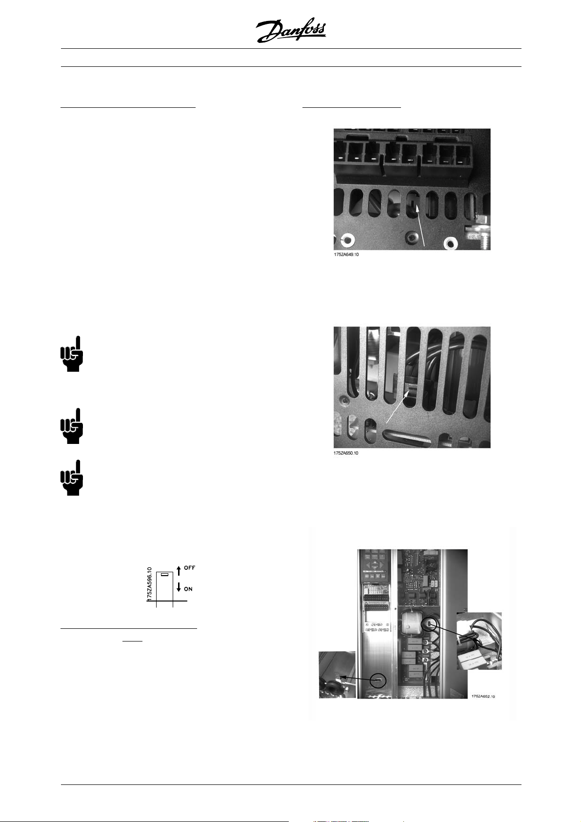
■RFI switch
ains supply isolated from earth:
M
If the frequency converter is supplied from an isolated
mains source ( IT mains) or TT/TN-S mains with
grounded leg, the RFI switch is recommended to
1)
be turned off (OFF)
. For further reference, see
IEC 364-3. In case optimum EMC performance is
needed, parallel motors are connected or the motor
cable length is above 25 m, it is recommended
to set the switch in ON position.
In OFF position, the internal RFI capacities (filter
capacitors) between the chassis and the intermediate
circuit are cut off to avoid damage to the intermediate
circuit and to reduce the earth capacity currents
(according to IEC 61800-3).
Please also refer to the application note VLT on
IT mains, MN.90.CX.02. It is important to use
isolation monitors that are capable for use together
with power electronics (IEC 61557-8).
NB!:
The RFI switch is not to be operated with
mains connected to the unit. Check that
the mains supply has been disconnected
before operating the RFI switch.
VLT®6000 HVAC Series
Position of RFI switches
Bookstyle IP 20
VLT 6002 - 6011 380 - 460 V
VLT 6002 - 6005 200 - 240 V
NB!:
Open RFI switch is only allowed at factory
set switching frequencies.
NB!:
The RFI switch connects the capacitors
galvanically to earth.
The red switches are operated by means of e.g. a
screwdriver. They are set in the OFF position when
they are pulled out and in ON position when they
are pushed in. Factory setting is ON.
Mains supply connected to earth:
The RFI switch must be in ON position in order for the
frequency converter to comply with the EMC standard.
1) Not possible with 6102-6652, 525-600 V units.
Compact IP 20 and NEMA 1
VLT 6002 - 6011 380 - 460 V
VLT 6002 - 6005 200 - 240 V
VLT 6002 - 6011 525 - 600 V
50
Compact IP 20 and NEMA 1
VLT 6016 - 6027 380 - 460 V
VLT 6006 - 6011 200 - 240 V
VLT 6016 - 6027 525 - 600 V
MG.61.A5.02 - VLT is a registered Danfoss trademark
Page 51
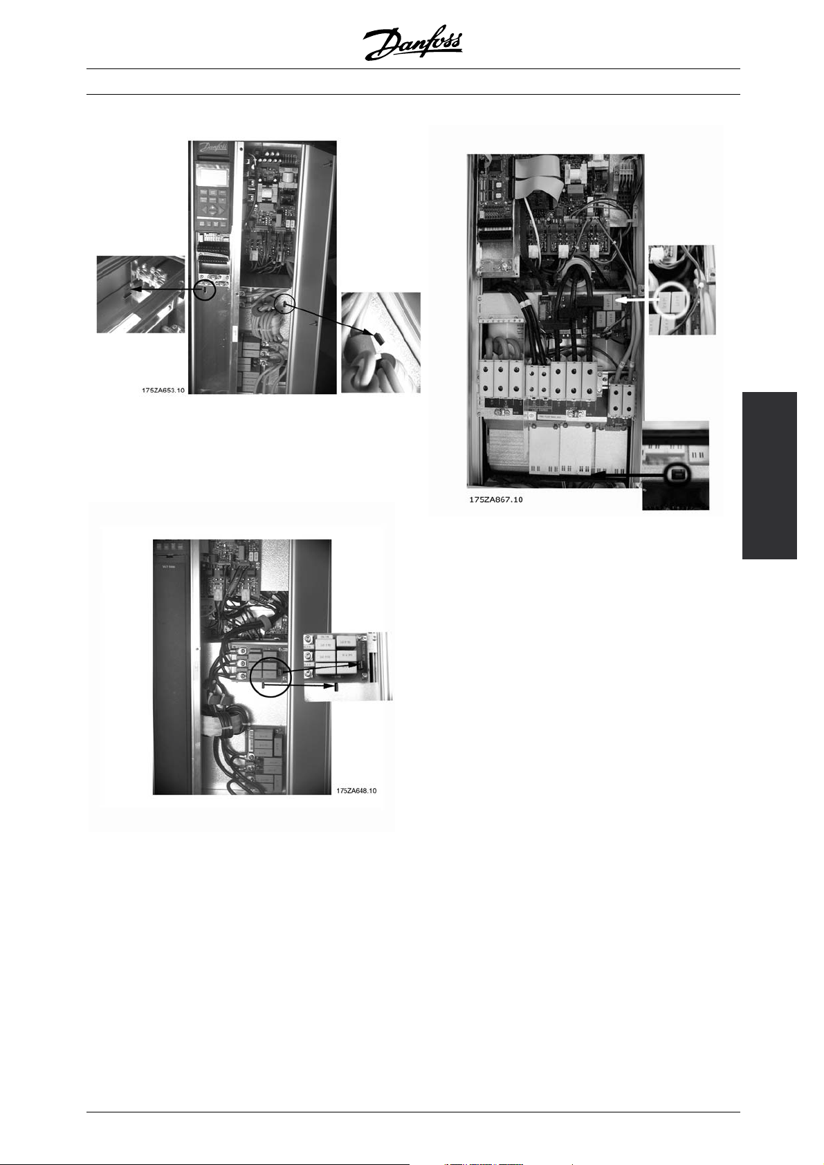
Compact IP 20 and NEMA 1
VLT 6032 - 6042 380 - 460 V
VLT 6016 - 6022 200 - 240 V
VLT 6032 - 6042 525 - 600 V
VLT®6000 HVAC Series
Installation
Compact IP 20 and NEMA 1
VLT 6052 - 6122 380 - 460 V
VLT 6027 - 6032 200 - 240 V
VLT 6052 - 6072 525 - 600 V
Compact IP 54
VLT 6102 - 6122 380 - 460 V
MG.61.A5.02 - VLT is a registered Danfoss trademark
51
Page 52
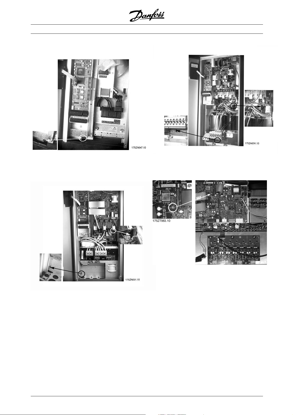
VLT®6000 HVAC Series
Compact IP 54
VLT 6002 - 6011 380 - 460 V
VLT 6002 - 6005 200 - 240 V
Compact IP 54
VLT 6016 - 6032 380 - 460 V
VLT 6006 - 6011 200 - 240 V
Compact IP 54
VLT 6042 - 6072 380 - 460 V
VLT 6016 - 6032 200 - 240 V
All enclosure types
VLT 6152 - 6602, 380 - 460 V
52
MG.61.A5.02 - VLT is a registered Danfoss trademark
Page 53
VLT®6000 HVAC Series
■High voltage test
A high voltage test can be carried out by short-circuiting
terminals U, V, W, L1, L2 and L3 and energizing
by max. 2.5 kV DC for one second between
this short-circuit and the chassis.
NB!:
The RFI switch must be closed (position
ON) when high voltage tests are carried out.
The mains and motor connection must be
interrupted in the case of high voltage tests of the total
installation if the leakage currents are too high.
■Heat emission from VLT 6000 HVAC
The tables in General technical data show the
power loss P
maximum cooling air temperature t
(W) from VLT 6000 HVAC. The
, is 40°
IN MAX
at 100% load (of rated value).
■Ventilation of integrated VLT 6000 HVAC
The quantity of air required for cooling frequency
converters can be calculated as follows:
1. AddupthevaluesofP
for all the frequency
converters to be integrated in the same panel.
The highest cooling air temperature (t
must be lower than t
(40°C). The day/night
IN, MAX
)present
IN
average must be 5°C lower (VDE 160). The
outlet temperature of the cooling air must not
exceed: t
OUT, MAX
(45° C).
2. Calculate the permissible difference between
the temperature of the cooling air (t
its outlet temperature (t
OUT
):
)and
IN
t = 45° C-tIN.
3. Calculate the required
quantity of air =
insert
tinKelvin
m3/h
The outlet from the ventilation must be placed above
the highest-mounted frequency converter. Allowance
must be made for the pressure loss across the
filters and for the fact that the pressure is going
to drop as the filters are choked.
■EMC correct electrical installation
Following these guidelines is recommended in cases
where compliance with EN 61000-6-3/4, EN 55011
or EN 61800-3 First environment is required. If the
installation is in EN 61800-3 Second environment,then
it is acceptable to deviate from these guidelines. It is
however not recommended. See also CE labelling,
Emission and EMC test results under special conditions
in the Design Guide for further details.
Good engineering practice to ensure EMC
correct electrical installation:
• Use only braided screened/armoured motor
cables and control cables.
The screen should provide a minimum coverage
of 80%. The screen material must be metal,
not limited to but typically copper, aluminium,
steel or lead. There are no special requirements
for the mains cable.
• Installations using rigid metal conduits are not
required to use screened cable, but the motor
cable must be installed in conduit separate from
the control and mains cables. Full connection
of the conduit from the drive to the motor is
required. The EMC performance of flexible
conduits varies a lot and information from the
manufacturer must be obtained.
• Connect the screen/armour/conduit to earth
at both ends for motor cables and control
cables. See also Earthing of braided screened/
armoured control cables.
• Avoid terminating the screen/armour with twisted
ends (pigtails). Such a termination increases the
high frequency impedance of the screen, which
reduces its effectiveness at high frequencies. Use
low impedance cable clamps or glands instead.
• Ensure good electrical contact between the
mounting plate and the metal chassis of the
frequency converter. This does not apply
to IP54 units as they are designed for wall
mounting and VLT 6152-6602, 380-480 V, VLT
6102-6652, 525-600 V, VLT 6042-6062, 200-240
VAC in IP20/NEMA1 enclosure.
• Use starwashers and galvanically conductive
installation plates to secure good electrical
connections for IP00, IP20, IP21 and
NEMA 1 installations.
• Avoid using unscreened/unarmoured motor
or control cables inside cabinets housing the
drive(s), where possible.
• An uninterrupted high frequency connection
between the frequency converter and the motor
units is required for IP54 units.
The illustration shows an example of an EMC correct
electrical installation of an IP20 or NEMA 1 frequency
converter. The frequency converter has been fitted
in an installation cabinet with an output contactor
and connected to a PLC, which in this example
is installed in a separate cabinet. Other ways of
Installation
MG.61.A5.02 - VLT is a registered Danfoss trademark
53
Page 54
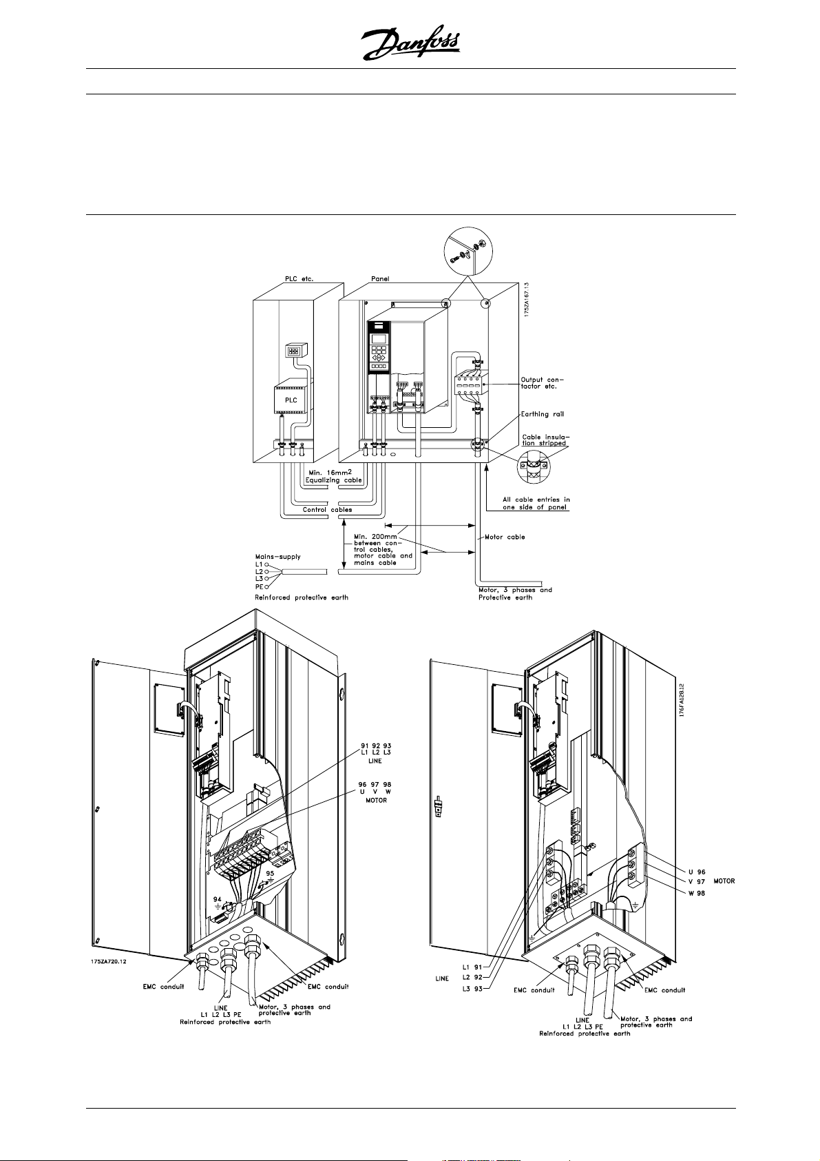
VLT®6000 HVAC Series
making the installation may have as good an EMC
performance, provided the above guide- lines to
engineering practice are followed. Please note that
when unscreened cables and control wires are used,
some emission requirements are not complied with,
although the immunity requirements are fulfilled.
See the section EMC test results for further details.
54
MG.61.A5.02 - VLT is a registered Danfoss trademark
Page 55

■Use of EMC-correct cables
Braided screened/armoured cables are recommended
to optimise EMC immunity of the control cables and
the EMC emission from the motor cables.
The ability of a cable to reduce the in- and outgoing
radiation of electric noise depends on the switching
impedance (Z
). The screen of a cable is normally
T
designed to reduce the transfer of electric noise;
however,ascreenwithalowerZ
effective than a screen with a higher Z
Z
is rarely stated by cable manufacturers, but
T
it is often possible to estimate Z
value is more
T
.
T
by assessing
T
the physical design.
VLT®6000 HVAC Series
ZTcan beassessed on the basis of the following factors:
- The contact resistance between the individual
screen conductors.
- The screen coverage, i.e. the physical area of the
cable covered by the screen - often stated as a
percentage value. Should be min. 85%.
- Screen type, i.e. braided or twisted pattern.
Aluminium-clad with copper wire.
Twisted copper wire or armoured steel wire cable.
Single-layer braided copper wire with varying
percentage screen coverage.
Double-layer braided copper wire.
Twin layer of braided copper wire with a magnetic,
screened/armoured intermediate layer.
Cable that runs in copper tube or steel tube.
Lead cable with 1.1 mm wall thickness with full
coverage.
Installation
MG.61.A5.02 - VLT is a registered Danfoss trademark
55
Page 56
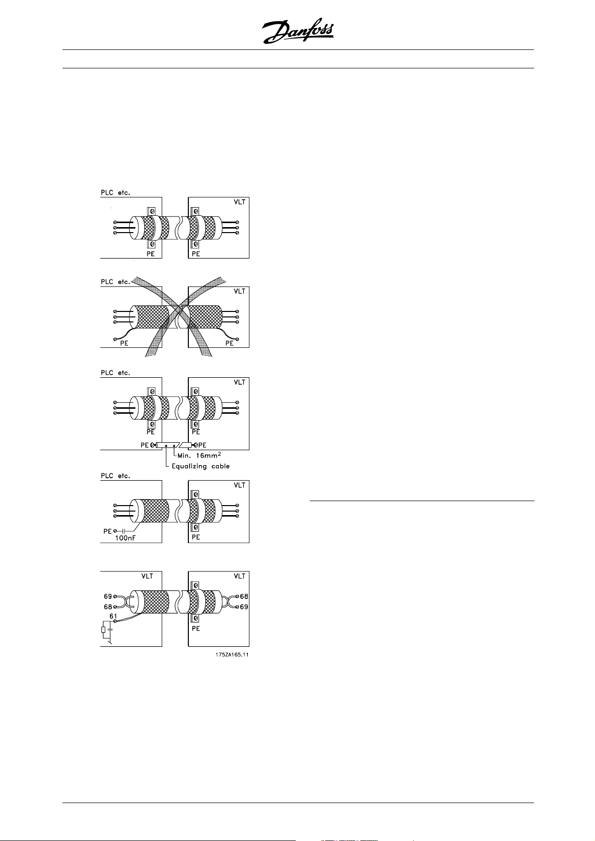
■Electrical installation - earthing of control cables
Generally speaking, control cables must be braided
screened/armoured and the screen must be
connected by means of a cable clamp at both
ends to the metal cabinet of the unit.
VLT®6000 HVAC Series
Correct earthing
Control cables and cables for serial communication
must be fitted with cable clamps at both ends to
ensure the best possible electrical contact
The drawing below indicates how correct earthing is
carried out and what to be done if in doubt.
Wrong earthing
Do not use twisted cable ends (pigtails), since these
increase the screen impedance at high frequencies.
Protection with respect to earth potential
between PLC and VLT
If the earth potential between the frequency converter
and the PLC (etc.) is different, electric noise may
occur that will disturb the whole system. This
problem can be solved by fitting an equalising cable,
to be placed next to the control cable. Minimum
2
cable cross-section: 16 mm
.
For 50/60 Hz earth loops
If very long control cables are used, 50/60 Hz earth
loops may occur. This problem can be solved by
connecting one end of the screen to earth via a
100nF capacitor (keeping leads short).
Cables for serial communication
Low-frequency noise currents between two frequency
converters can be eliminated by connecting one end of
the screen to terminal 61. This terminal is connected
to earth via an internal RC link. It is recommended
to use twisted-pair cables to reduce the differential
mode interference between the conductors.
56
MG.61.A5.02 - VLT is a registered Danfoss trademark
Page 57
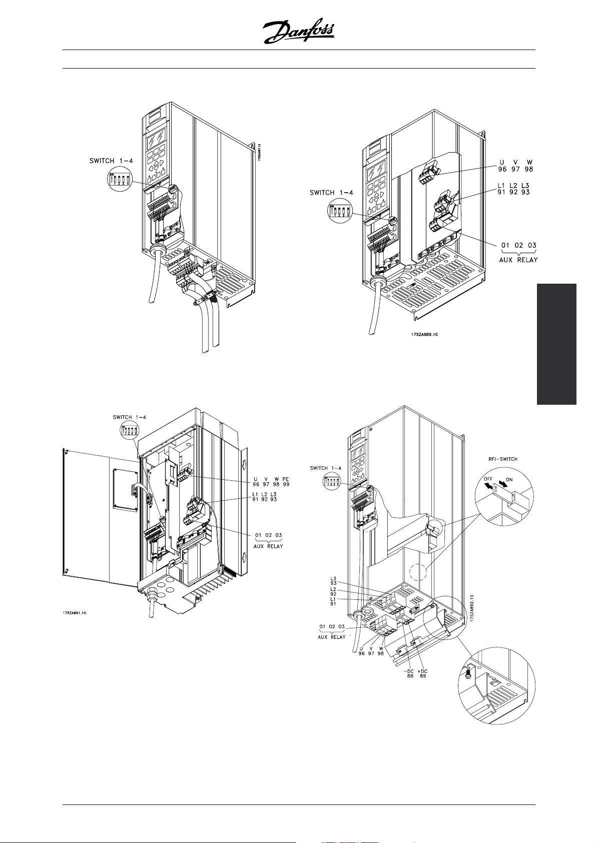
■Electrical installation, enclosures
VLT®6000 HVAC Series
Bookstyle IP 20
VLT 6002-6005, 200-240 V
VLT 6002-6011, 380-460 V
Compact IP 54
VLT 6002-6005, 200-240 V
VLT 6002-6011, 380-460 V
Compact IP 20 and NEMA 1 (IP 20)
VLT 6002-6005, 200-240 V
VLT 6002-6011, 380-460 V
VLT 6002-6011, 525-600 V
Installation
MG.61.A5.02 - VLT is a registered Danfoss trademark
Compact IP 20 and NEMA 1
VLT 6006-6032, 200-240 V
VLT 6016-6072, 380-460 V
VLT 6016-6072, 525-600 V
57
Page 58

VLT®6000 HVAC Series
Compact IP 00
VLT 6042-6062, 200-240 V
Compact IP 54
VLT 6006-6032, 200-240 V
VLT 6016-6072, 380-460 V
Compact IP 54
VLT 6042-6062, 200-240 V
Compact NEMA 1 (IP 20)
VLT 6042-6062, 200-240 V
58
MG.61.A5.02 - VLT is a registered Danfoss trademark
Page 59

Compact IP 20
VLT 6102-6122, 380-460 V
VLT®6000 HVAC Series
IP 54, IP 21/NEMA 1
VLT 6152-6172, 380-460 V
VLT 6102-6172, 525-600 V
Installation
Compact IP 54
VLT 6102-6122, 380-460 V
MG.61.A5.02 - VLT is a registered Danfoss trademark
IP 00
VLT 6152-6172, 380-460 V
VLT 6102-6172, 525-600 V
Note: The RFI switch has no function in
the 525-600 V drives.
59
Page 60

VLT®6000 HVAC Series
■Electrical installation, power cables
IP 54, IP 21/NEMA 1 with disconnect and main fuse
VLT 6222-6352, 380-460 V
VLT 6222-6402, 525-600 V
Compact IP 00 with disconnect and fuse
VLT 6402-6602 380-460 V and VLT
6502-6652 525-600 V
IP 00 with disconnect and fuse
VLT 6222-6352, 380-460 V
VLT 6222-6402, 525-600 V
Note: The RFI switch has no function in
the 525-600 V drives.
60
Compact IP 00 without disconnect and fuse
VLT 6402-6602 380-460
6502-6652 525-600 V
Note: The RFI switch has no function in
the 525-600 V drives.
MG.61.A5.02 - VLT is a registered Danfoss trademark
VandVLT
Page 61

Position of earth terminals, IP 00
VLT®6000 HVAC Series
Position of earth terminals, IP 21 / IP 54
Compact IP 21 / IP 54 without disconnect and fuse
VLT 6402-6602 380-460 V and VLT
6502-6652 525-600 V
Note: The RFI switch has no funct
the 525-600 V drives.
ion in
Installation
MG.61.A5.02 - VLT is a registered Danfoss trademark
61
Page 62

■Electrical installation, power cables
Bookstyle IP 20
VLT 6002-6005, 200-240 V
VLT 6002-6011, 380-460 V
VLT®6000 HVAC Series
Compact IP 20, NEMA 1, and IP 54
VLT 6002-6005, 200-240 V
VLT 6002-6011, 380-460 V
VLT 6002-6011, 525-600 V
IP 20 and NEMA 1
VLT 6006-6032, 200-240 V
VLT 6016-6122, 380-460 V
VLT 6016-6072, 525-600 V
IP 54
VLT 6006-6032, 200-240 V
VLT 6016-6072, 380-460 V
62
MG.61.A5.02 - VLT is a registered Danfoss trademark
Page 63

■Electrical installation, power cables
IP 00 and NEMA 1 (IP 20)
VLT 6042-6062, 200-240 V
VLT®6000 HVAC Series
IP 54
VLT 6042-6062, 200-240 V
Installation
Compact IP 54
VLT 6102-6122, 380-460 V
MG.61.A5.02 - VLT is a registered Danfoss trademark
63
Page 64
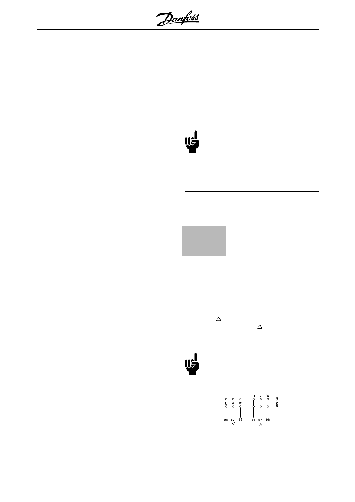
VLT®6000 HVAC Series
■Tightening-up torque and screw sizes
The table shows the torque required when fitting
terminals to the frequency converter. For VLT
6002-6032, 200-240 V, VLT 6002-6122, 380-460 and
VLT 6002-6072 525-600 V the cables must be fastened
with screws. For VLT 6042-6062, 200-240 V and
for VLT 6152-6550, 380-460 V and VLT 6102-6652,
525-600 V the cables must be fastened with bolts.
These figures apply to the following terminals:
Mains terminals (Nos.) L1, L2, L3
Motor terminals (Nos.) U, V, W
Earth terminal (Nos.) 94, 95, 99
VLT type
3 x 200 - 240 V
VLT 6002-6005 0.5-0.6 Nm M3
VLT 6006-6011 1.8 Nm (IP 20) M4
VLT 6006-6016 1.8 Nm (IP 54) M4
VLT 6016-6027 3.0 Nm (IP 20) M5
VLT 6022-6027 3.0 Nm (IP 54)
VLT 6032 6.0 Nm M6
VLT 6042-6062 11.3 Nm M8 (bolt)
VLT type
3 x 380-460 V
VLT 6002-6011 0.5-0.6 Nm M3
VLT 6016-6027 1.8 Nm (IP 20) M4
VLT 6016-6032 1.8 Nm (IP 54) M4
VLT 6032-6052 3.0 Nm (IP 20) M5
VLT 6042-6052 3.0 Nm (IP 54)
VLT 6062-6072 6.0 Nm M6
VLT 6102-6122 15 Nm (IP 20) M8
VLT 6152-6352 19 Nm
VLT 6402-6602 19 Nm M10
VLT type
3 x 525-600 V
VLT 6002-6011 0.5-0.6 Nm M3
VLT 6016-6027 1.8 Nm M4
VLT 6032-6042 3.0 Nm
VLT 6052-6072 6.0 Nm M6
VLT 6102-6402 19 Nm
VLT 6502-6652 19 Nm M10
Tightening-up
torque
2)
Tightening-up
torque
2)
24 Nm (IP 54)
9.5 Nm M8 (box lug)
Tightening-up
torque
9.5 Nm M8 (box lug)
1) 3)
4)
2)
4)
91, 92, 93
96, 97, 98
Screw/bolt
size
3)
3)
M5
3)
Screw/bolt
size
3)
3)
M5
3)
3)
M10 (bolt)
(compression
5)
lug)
Screw/bolt
size
3)
M5
3)
M10 (bolt)
(compression
5)
lug)
5)
5)
5)
5)
Tool
4mm
4mm
5mm
Tool
4mm
4mm
5mm
6mm
8mm
16 mm
16 mm
13 mm
Tool
4mm
5mm
16 mm
16 mm
13 mm
4. Loadsharing terminals 9.5 Nm/M8 (bolt)
5. Wrench
■Mains connection
Mains must be connected to terminals 91, 92, 93.
Mains voltage 3 x 200-240 V
91, 92, 93 Mains voltage 3 x 380-460 V
L1, L2, L3 Mains voltage 3 x 525-600 V
NB!:
Check that the mains voltage fits the mains
voltage of the frequency converter, which
can be seen from the nameplate.
See Technical data for correct sizing of cable
cross-sections.
■Motor connection
The motor must be connected to terminals 96,
97, 98. Earth to terminal 94/95/99.
Nos.
96. 97. 98
U, V, W
No. 94/95/99 Earth connection
Motor voltage 0-100 % of mains voltage
See Technical data for correct sizing of cable
cross-sections.
All types of three-phase asynchronous standard motors
canbeusedwithaVLT6000HVACunit.
Small-size motors are normally star-connected.
(220/380 V,
delta-connected (380/660 V,
/Y). Large-size motors are
/Y). The correct
connection and voltage can be read from
the motor nameplate.
NB!:
In older motors without phase coil
insulation, a LC filter should be fitted to
the frequency converter output. See the
Design Guide or contact Danfoss.
1. Loadsharing terminals 14 Nm/M6, 5 mm Allen key
2. IP 54 units with RFI filter line terminals 6 Nm
3. Allen screws (hexagon)
64
MG.61.A5.02 - VLT is a registered Danfoss trademark
Page 65
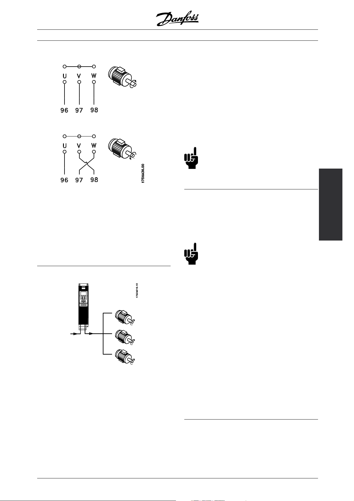
■Direction of motor rotation
The factory setting is for clockwise rotation with the
frequency transformer output connected as follows.
Terminal 96 connected to U-phase
Terminal 97 connected to V-phase
Terminal 98 connected to W-phase
VLT®6000 HVAC Series
Problems may arise at the start and at low rpm values
if the motor sizes are widely different. This is because
the relatively high ohmic resistance in small motors
calls for a higher voltage at the start and at low rpm
values. In systems with motors connected in parallel,
theelectronicthermalrelay(ETR)ofthefrequency
converter cannot be used as motor protection for
the individual motor. Consequently, additional motor
protection is required, such as thermistors in each
motor (or individual thermal relays).
NB!:
Parameter 107 Automatic Motor Adaptation,
AMA and Automatic Energy Optimization,AEO
in parameter 101 Torque characteristics cannot
be used if motors are connected in parallel.
■Motor cables
See Technical data for correct sizing of motor
cable cross-section and length.
Always comply with national and local regulations
on cable cross-sections.
Installation
The direction of motor rotation can be changed by
switching two phases in the motor cable.
■Parallel coupling of motors
VLT 6000 HVAC is able to control several motors
connected in parallel. If the motors are to have different
rpmvalues,themotorsmusthavedifferentrated
rpm values. Motor rpm is changed simultaneously,
which means that the ratio between the rated
rpm values is maintained across the range. The
total current consumption of the motors is not
to exceed the maximum rated output current
for the frequency converter.
I
VLT,N
NB!:
If an unscreened cable is used, some
EMC requirements are not complied with,
see EMC test results.
If the EMC specifications regarding emission are
to be complied with, the motor cable must be
screened, unless otherwise stated for the RFI filter
in question. It is important to keep the motor cable
as short as possible so as to reduce the noise level
and leakage currents to a minimum.
The motor cable screen must be connected to the
metal cabinet of the frequency converter and to the
metal cabinet of the motor. The screen connections
are to be made with the biggest possible surface (cable
clamp). This is enabled by different installation devices
in the differentT frequency converters. Mounting with
twisted screen ends (pigtails) is to be avoided, since
these spoil the screening effect at higher frequencies.
If it is necessary to break the screen to install a motor
isolator or motor contactor, the screen must be
continued at the lowest possible HF impedance.
MG.61.A5.02 - VLT is a registered Danfoss trademark
65
Page 66
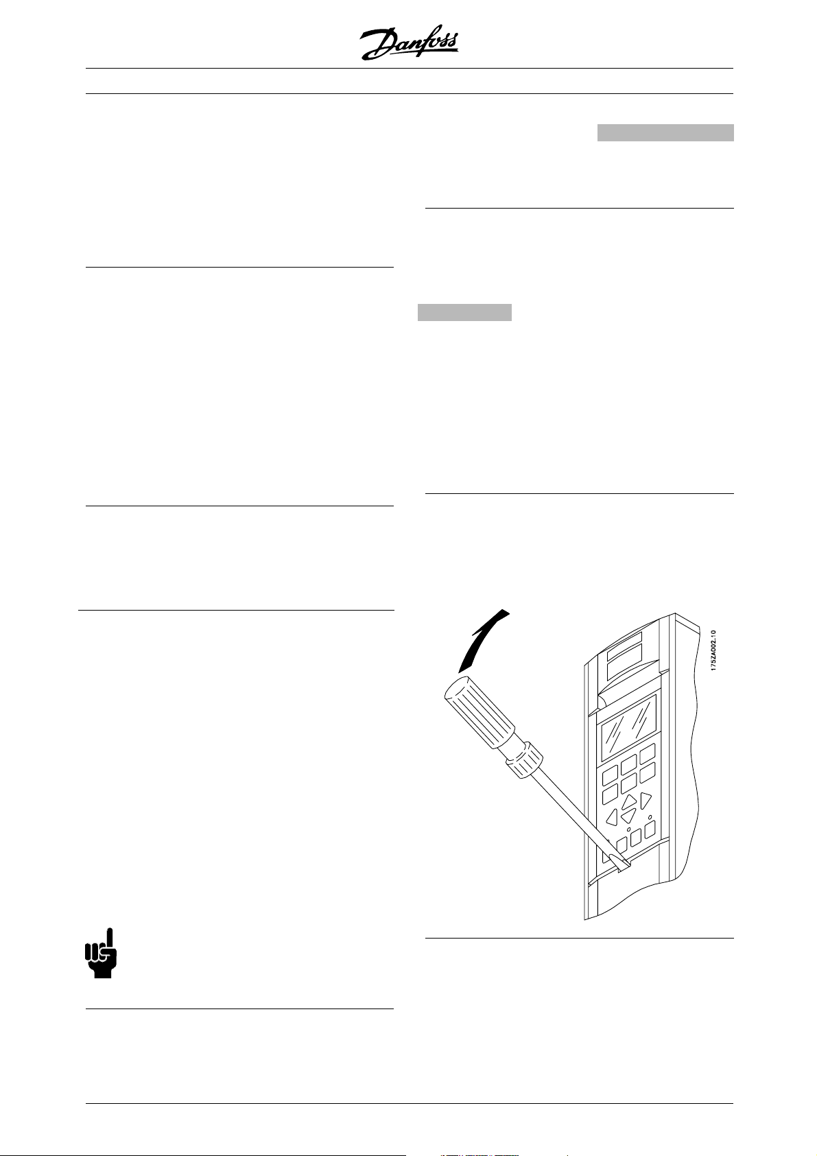
VLT®6000 HVAC Series
■Motor thermal protection
The electronic thermal relay in UL-approved frequency
converters has received UL-approval for single motor
protection, as long as parameter 117 Motor thermal
protection has been set to ETR Trip and parameter 105
Motor current I
, has been programmed for the rated
VLT,N
motor current (can be read from the motor nameplate).
■Earth connection
Since the leakage currents to earth may be higher
than 3.5 mA, the frequency converter must always
be earthed in accordance with applicable na-tional
and local regulations. In order to ensure good
mechanical connection of the earth cable, its cable
2
cross-section must be at least 10 mm
. For added
security, an RCD (Residual Current Device) may be
installed. This ensures that the frequency converter
will cut out if the leakage currents get too high.
See RCD instructions MI.66.AX.02.
■Installation of 24 Volt external DC supply
Torque: 0.5 - 0.6 Nm
Screw size:
M3
No. Function
35(-), 36 (+) 24 V External DC supply
(Available with VLT 6152-6602 380-460 V and VLT 6102-6652,
525-600 V only)
Te rm in a l n os . 8 8, 8 9
Contact Danfoss if you require further information.
■High-voltage relay
The cable for the high-voltage relay must be connected
to terminals 01, 02, 03. The high-voltage relay is
programmed in parameter 323, Relay 1, out-put.
No. 1 Relay ouput 1
1+3 break, 1+2 make
Max 240 V AC, 2 Amp
Min. 24 V DC 10 mA or
24 V AC, 100 mA
Max Cross-section: 4 mm
Torque: 0.5-0.6 Nm
Screw size: M3
2
/10 AWG
■Control card
All terminals for the control cables are located under
the protective cover of the frequency converter. The
protective cover (see drawing below) can be removed
by means of a pointed object - a screwdriver or similar.
24 V external DC supply can be used as low-voltage
supply to the control card and any option cards
installed. T
his enables full operation of the LCP (incl.
parameter setting) without connection to mains.
Please note that a warning of low voltage will be
given wh
en 24 V DC has been connected; however,
there will be no tripping. If 24 V external DC supply
is connected or switched on at the same time as the
supply, a time of min. 200 msec. must be set
mains
in parameter 111, Start delay .Apre-fuseofmin.6
Amp, slow-blow, can be fitted to protect the external
V DC supply. The power consumption is 15-50
24
W, depending on the load on the control card.
NB!:
Use24VDCsupplyoftypePELVtoensure
correct galvanic isolation (type PELV) on the
control terminals of the frequency converter.
■DC bus connection
The DC bus terminal is used for DC back-up,
with the intermediate circuit being supplied
from an external DC source.
66
MG.61.A5.02 - VLT is a registered Danfoss trademark
Page 67
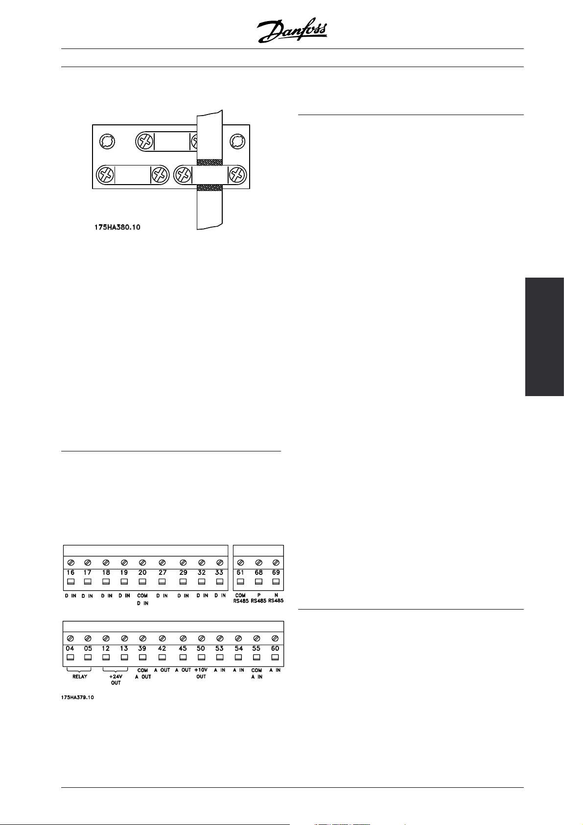
■Electrical installation, control cables
Torque: 0.5-0.6 Nm
Screw size: M3
Generally speaking, control cables must be screened/
armoured and the screen must be connected by means
of a cable clamp at both ends to the metal cabinet of
the unit (see Earthing of screened/ armoured control
cables). Normally, the screen must also be connected
to the body of the controlling unit (follow the instructions
for installation given for the unit in question).
If very long control cables are used, 50/60 Hz
earth loops may occur that will disturb the whole
system. This problem can be solved by connecting
one end of the screen to earth via a 100nF
condenser (keeping leads short).
■Electrical installation, control cables
2
Max. control cable cross section: 1.5 mm
/16 AWG
Torque: 0.5-0.6 Nm
Screw size: M3
See Earthing of screened/armoured control cables
for correct termination of control cables.
VLT®6000 HVAC Series
No. Function
04, 05 Relay output 2 can be used for indicating
status and warnings.
12, 13 Voltage supply to digital inputs. For the 24 V
DC to be used for digital inputs, switch 4 on
the control card must be closed, position "on".
16-33 Digital inputs. See parameters 300-307 Digital
inputs.
20 Ground for digital inputs.
39 Ground for analogue/digital outputs. Must
be connnected to terminal 55 by means of
a three-wire transmitter. See Examples of
connection.
42, 45 Analogue/digital outputs for indicating
frequency, reference, current and torque. See
parameters 319-322 Analogue/digital outputs.
50 Supply voltage to potentiometer and thermistor
10 V DC.
53, 54 Analogue voltage input, 0 - 10 V DC.
55 Ground for analogue voltage inputs.
60 Analogue current input 0/4-20 mA. See
parameters 314-316 Terminal 60.
61 Termination of serial communication. See
Earthing of screened/armoured control cables.
This terminal is not normally to be used.
68, 69 RS 485 interface, serial communication.
Where the frequency converter is connected
to a bus, switches 2 and 3 (switches 1- 4 see next page) must be closed on the first and
the last frequency converter. On the remaining
frequency converters, switches 2 and 3 must
be open. The factory setting is closed (position
on).
Installation
MG.61.A5.02 - VLT is a registered Danfoss trademark
67
Page 68
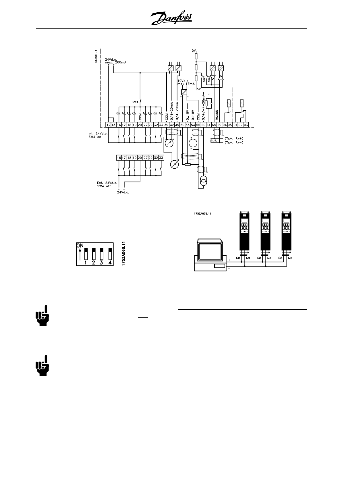
VLT®6000 HVAC Series
■Switches 1-4
The dipswitch is located on the control card. It is used
for serial communication and external DC suppl
The switching position shown is the factory setting.
Switch 1 has no function.
Switches 2 and 3 are used for terminating an RS-485
interface to the serial communication bus
NB!:
When the frequency converter is the
ast device on the serial communication bus,
l
switches 2 and 3 must be ON in that designated
ny other VLTs on the serial communication bus
VLT. A
must have switches 2 and 3 set to OFF.
NB!:
Please note that when Switch 4 is in position
"OFF," the external 24 V DC supply is galvanically
isolated from the frequency converter.
first or
y.
In order to avoid potential equalizing currents in the
screen, the cable screen can be earthed via terminal
61, which is connected to the frame via an RC-link.
■Bus connection
The serial bus connection in accordance with the RS
485 (2-conductor) norm is connected to terminals
68/69 of the frequency converter (signals P and N).
Signal P is the positive potential (TX+,RX+), while
signal N is the negative potential (TX-,RX-).
If more than one frequency converter is to be connected
to a given master, use parallel connections.
68
MG.61.A5.02 - VLT is a registered Danfoss trademark
Page 69
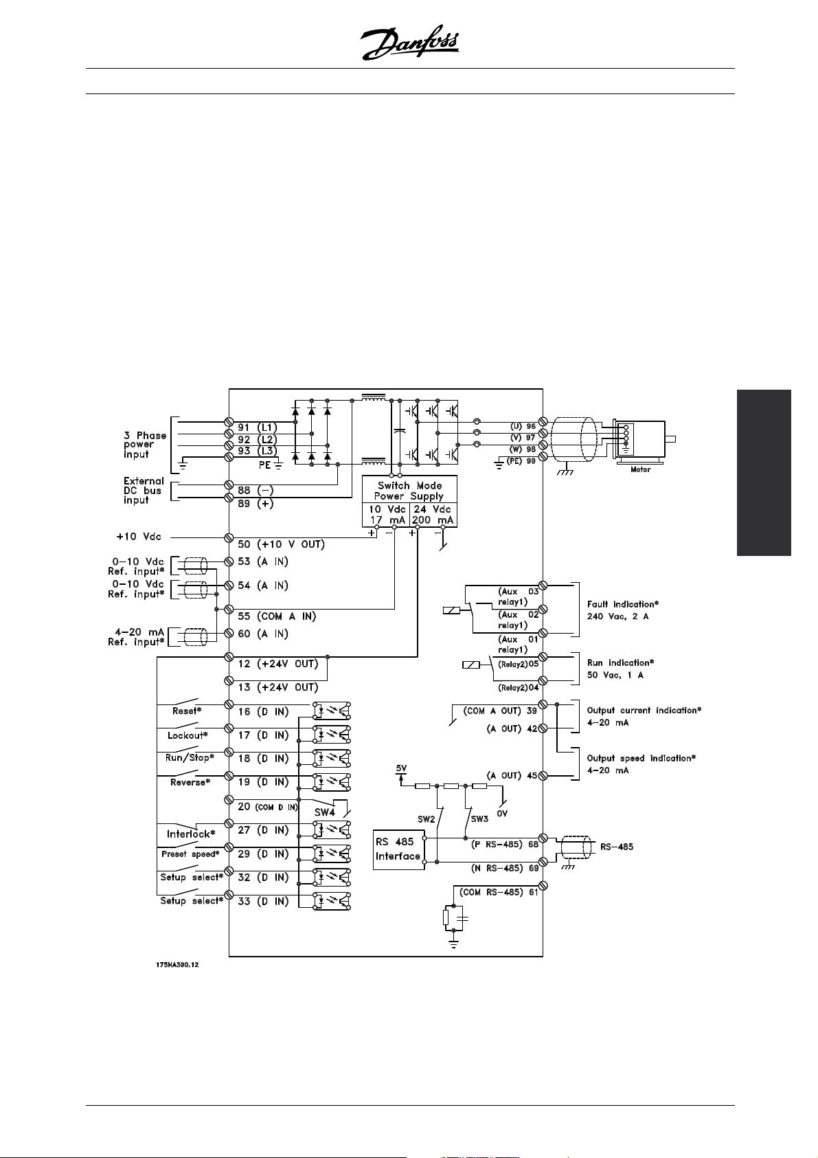
■Connection examples, VLT 6000 HVAC
The diagram below gives an example of a typical
VLT 6000 HVAC installation.
The mains supply is connected to terminals 91 (L1),
92 (L2) and 93 (L3), while the motor is connected to
96 (U), 97 (V) and 98 (W). These numbers can also be
seen from the terminals of the frequency converter.
An external DC supply or a 12-pulse option can
be connected to terminals 88 and 89. Please ask
Danfoss for a Design Guide to learn more.
Analogue inputs can be connected to terminals 53 [V],
54 [V] and 60 [mA]. These inputs can be programmed
for either reference, feedback or thermistor. See
Analogue inputs in parameter group 300.
VLT®6000 HVAC Series
There are 8 digital inputs, which can be connected
to terminals 16-19, 27, 29, 32, 33. These inputs
can be programmed in accordance with the table
in Inputs and outputs 300-328.
There are two analogue/digital outputs (terminals
42 and 45), which can be programmed to show
the present status or a process value, such as
. Relay outputs 1 and 2 can be used for
0-f
MAX
giving the present status or a warning.
On terminals 68 (P+) and 69 (N-) RS 485 interface,
the frequency converter can be controlled and
monitored via serial communication.
Installation
MG.61.A5.02 - VLT is a registered Danfoss trademark
69
Page 70
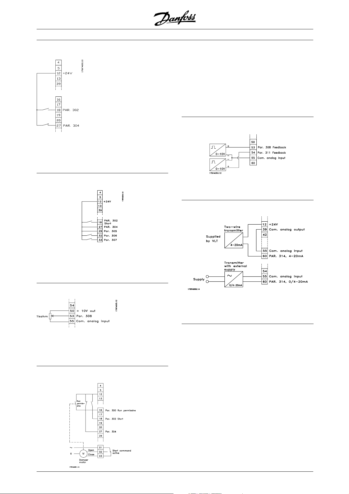
VLT®6000 HVAC Series
■Single-pole start/stop
- Start/stop using terminal 18.
Parameter 302 = Start [1]
- Quick-stop using terminal 27.
Parameter 304 = Coasting stop, inverse [0]
■Digital speed up/down
- Start permitted with terminal 16.
Parameter 300 = Run permissive [8]
- Start/stop with terminal 18.
Parameter 302 = Start [1]
- Quickstop with terminal 27.
Parameter 304 = Coasting stop, inverse [0].
- Activated damper (motor)
Parameter 323 = Start command active [13].
■2-zone regulation
- Parameter 308 = Feedback [2].
- Parameter 311 = Feedback [2].
■Transmitter connection
- Speed up and down using terminals 32 and 33.
Parameter 306 = Speed up [7]
Parameter 307 = Speed down [7]
Parameter 305 = Freeze reference [2]
■Potentiometer reference
-Parameter 308 = Reference [1]
Parameter 309 = Terminal 53, min. scaling
Parameter 310 = Terminal 53, max. scaling
■Run permissive
- Parameter 314 = Reference [1]
- Parameter 315 = Terminal 60, min. scaling
- Parameter 316 = Terminal 60, max. scaling
70
MG.61.A5.02 - VLT is a registered Danfoss trademark
Page 71
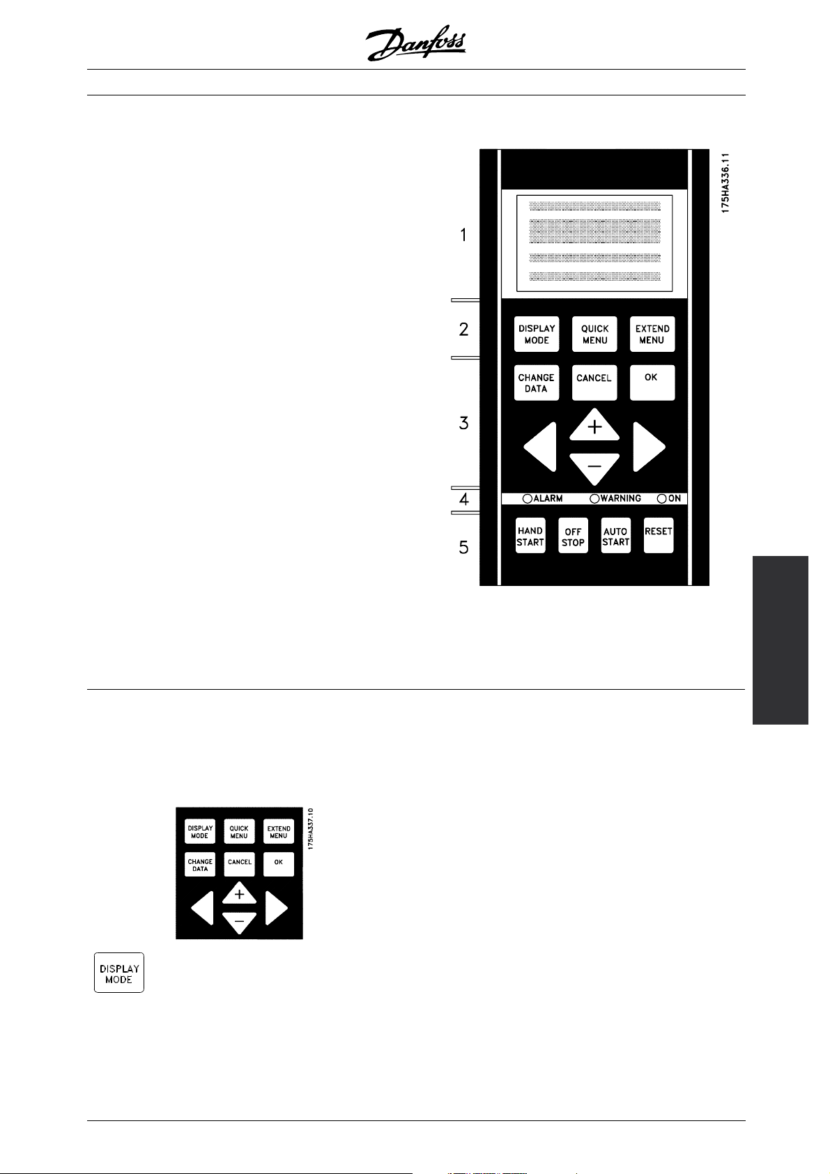
■Control unit LCP
The front of the frequency converter features a
control panel - LCP(Local Control Panel). This is a
complete interface for operation and programming
of the frequency converter.
The control panel is detachable and can - as an
alternative - be installed up to 3 metres away from
the frequency converter, e.g. on the front panel,
by means of a mounting kit option.
The functions of the control panel can be
divided into five groups:
1. Display
2. Keys for changing display mode
3. Keys for changing program parameters
4. Indicator lamps
5. Keys for local operation
All data are indicated by means of a 4-line alphanumeric
display, which, in normal operation, is able to show
4 operating data values and 3 operating condition
values continuously. During programming, all the
information required for quick, effective parameter
Setup of the frequency converter will be displayed.
As a supplement to the display, there are three
indicator lamps for voltage (ON), warning (WARNING)
and alarm (ALARM), respectively.
All frequency converter parameter Setups can be
changed immediately via the control panel, unless this
function has been programmed to be Locked [1] via
parameter 016 Lock for data change or via a digital
input, parameters 300-307 Data change lock.
VLT®6000 HVAC Series
Programming
■Control keys for parameter setup
The control keys are divided into functions. This means
that the keys between display and indicator lamps
are used for parameter Setup, including selecting the
display indication during normal operation.
[DISPLAY MODE] is used for selecting
theindicationmodeofthedisplayor
whenreturningtotheDisplaymode
from either the Quick menu or the
Extend menu mode.
MG.61.A5.02 - VLT is a registered Danfoss trademark
71
Page 72
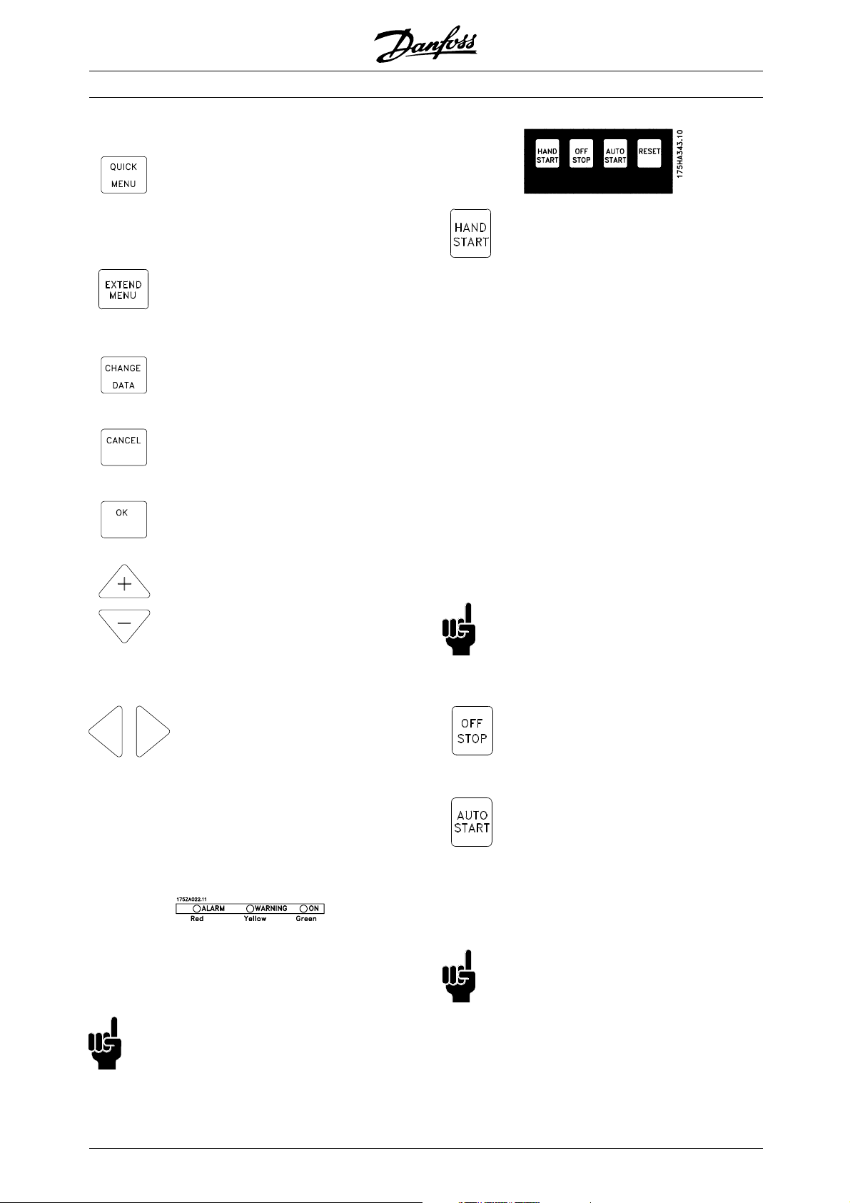
[QUICK MENU] gives access to the
parameters used for the Quick menu.
It is possible to switch between the
Quick menu and the Extend menu
modes.
[EXTEND MENU] gives access to all
parameters. It is possible to switch
between the Extend menu and the
Quick menu modes.
[CHANGE DATA] is used for changing
a setting selected either in the Extend
menu or the Quick menu mode.
[CANCEL] is used if a change of
the selec-ted parameter is not to be
carried out.
[OK] is used for confirming a change
of the parameter selected.
[+/-] is used for selecting parameters
and for changing a chosen parameter.
These keys are also used to change
the local reference.
In addition, the keys are used in
Display mode to switch between
operation variable readouts.
VLT®6000 HVAC Series
[HAND START] is used if the frequency
converter is to be controlled via the
control unit. The frequency converter
will start the motor, since a start
command is given by means of [HAND
START].
On the control terminals, the following
control signals will still be active when
[HAND START] is activated:
• Hand start - Off stop - Auto start
• Safety Interlock
• Reset
• Coasting stop inverse
• Reversing
• Setup select lsb - Setup select msb
• Jog
• Run permissive
• Lock for data change
• Stop command from serial
communication
NB!:
If parameter 201 Output frequency low limit
issettoanoutputfrequencygreaterthan
f
MIN
0 Hz, the motor will start and ramp up to this
frequency when [HAND START] is activated.
[<>] is used when selecting a
parameter group and for moving
the cursor when changing numerical
values.
■Indicator lamps
At the bottom of the control panel is a red
alarm lamp and a yellow warning lamp, as well
as a green voltage LED.
If certain threshold values are exceeded, the
alarm and/ or warning lamp is activated, and a
status or alarm text is displayed.
NB!:
The voltage indicator lamp is activated when
the frequency converter receives voltage.
■Local control
Underneath the indicator lamps are keys
for local control.
[OFF/STOP] is used for stopping the
connected motor. Can be selected as
Enable [1] or Disable [0] via parameter
013. If the stop function is activated,
line 2 will flash.
[AUTO START] is used if the frequency
converter is to be controlled via
the control terminals and/or serial
communication. When a start signal is
active on the control terminals and/or
the bus, the frequency converter will
start.
NB!:
An active HAND-OFF-AUTO signal via the digital
inputs will have higher priority than the control
keys [HAND START]-[AUTO START].
72
MG.61.A5.02 - VLT is a registered Danfoss trademark
Page 73
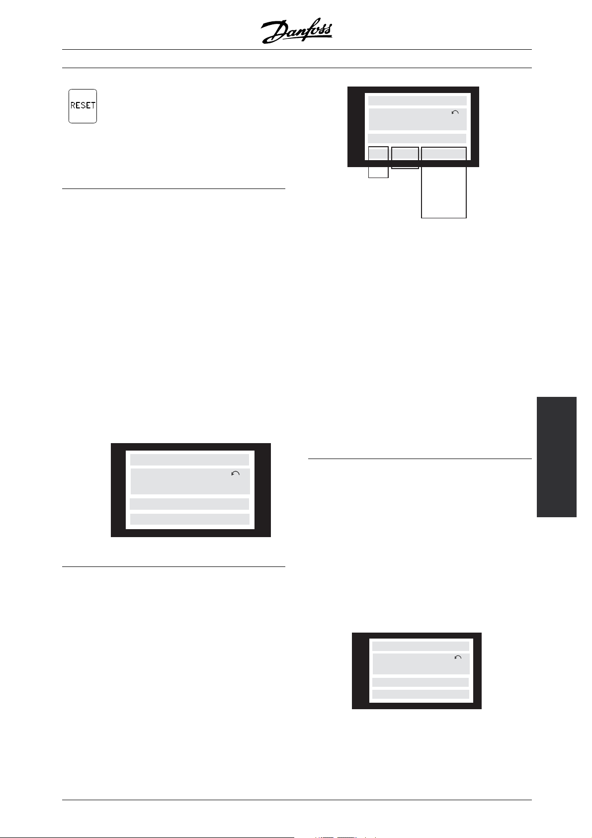
VLT®6000 HVAC Series
[RESET] is used for resetting the
frequency converter after an alarm
(trip). Can be selected as Enable [1]
or Disable [0] via parameter 015 Reset
on LCP.
See also List of warnings and alarms.
■Display mode
In normal operation, any 4 different operating variables
can be indicated continuously: 1.1 and 1.2 and
1.3 and 2. The present operating s
and warnings that have arisen are shown in line 2
in the form of a number. In the case of alarms, the
alarm in question will be sho
accompanied by an explanatory note. Warnings will
flashinline2,withanexplanatorynoteinline1. In
addition, the displ
The arrow indicates the direction of rotation; here the
frequency converter has an active reversing signal. The
arrow body disapp
the output frequency falls below 0.01 Hz. The bottom
line gives the status of the frequency converter.
The scroll lis
data that can be shown for variable 2 in display mode.
Changes are made via the [+/-] keys.
ay shows the active Setup.
ears if a stop command is given or if
t on the next page gives the operating
tatus or alarms
wn in lines 3 and 4,
The left part of the status line indicates the
control ele-ment of the frequency converter that is
active. AUTO means that control is via the control
terminals, while HAND indicates that control is via
the local keys on the control unit.
OFF means that the frequency converter ignores all
control commands and stops the motor.
The centre part of the status line indicates the
refe-rence element that is active. REMOTE means
that the reference from the control terminals is active,
while LOCAL indicates that the reference is determined
via the [+/-] keys on the control panel.
The last part of the status line indicates the current
195NA113.10
status, for example "Running", "Stop" or "Alarm".
80.0% 5.08A 2.15kW
40.0Hz
AUTO REMOTE RUNNING
HAND LOCAL STOP
OFF
LOCAL STOPRAMPING
HAND JOGGING
.
.
.
.
STAND BY
SETUP
1
175ZA701.10
1st line
2nd line
VAR 1.1 VAR 1.2 VAR 1.3
SETUP
VAR 2
1
3rd line
STATUS
4th line
■Display mode , cont.
Three operating data values can be shown in the first
display line, while one operating variable can be shown
in the second display line. To be programmed via
parameters 007, 008, 009 and 010 Display read-out.
• Status line (4th line):
■DisplaymodeI:
VLT 6000 HVAC offers different display modes depending on the mode selected for the frequency
converter. The figure on the next page shows t
to navigate between different display modes.
Below is a display mode, in which the frequency
converter is in Auto mode with remote ref
at an output frequency of 40 Hz.
In this display mode, reference and control are
determined via the control terminals.
The text in line 1 gives the operating variable
shown in line 2.
FREQUENCY
40.0Hz
AUTO REMOTE RUNNING
Line 2 gives the current output frequency
and the active Setup.
SETUP
1
Programming
he way
erence
175ZA683.10
MG.61.A5.02 - VLT is a registered Danfoss trademark
73
Page 74

Line 4 says that the frequency converter is in Auto mode
with remote reference, and that the mo tor is running.
■Display mode II:
This display mode makes it possible to have three
operating data values displayed at the same time in
line 1. The operating data values are determined
in parameters 007-010 Display readout.
100% 7.8A 5.9kW
SETUP
50.0Hz
AUTO REMOTE RUNNING
■Display mode III:
This display mode is active as long as the [DISPLAY
MODE] key is kept depressed. In the first line,
operating data names and units of operating data
are displayed. In the second line, operating data 2
remains unchanged. When the key is released, the
different operating data values are shown.
1
VLT®6000 HVAC Series
175ZA685.10
REF% CURR.A.POW.,KW
SETUP
50.0Hz
AUTO REMOTE RUNNING
■Display mode IV:
This display mode is only active in connection with
local reference, see also Reference handling.Inthis
display mode, the reference is determined via the
[+/-] keys and control is carried out by means of the
keys underneath the indicator lamps. The first line
indicates the required reference. The third line gives
the relative value of the present output frequency at
any given time in relation to the maximum frequency.
The display is in the form of a bar graph.
USE +/- 40Hz
40.0Hz
----60
0
HAND LOCAL RUNNING
1
SETUP
1
175ZA695.10
176FA156.10
74
MG.61.A5.02 - VLT is a registered Danfoss trademark
Page 75

■Navigation between display modes
Press briefly
HAND LOCAL RUNNING
USE +/- 40Hz
40.0Hz
FREQUENCY
40.0Hz
AUTO REMOTE RUNNING
▲▲
▲
▲▲
SETUP
1
Display mode I
With remote
reference
VLT®6000 HVAC Series
▲▲
▲
▲▲
▲▲
▲
▲▲
80% 7,8A 5,9 KW
40.0 Hz
0 ---- 60
HAND LOCAL RUNNING
Display mode IV
175ZA697.10
▲▲
▲▲
▲
With local reference
Keep the [DISPLAY
MODE] key down
AUTO REMOTE RUNNING
Display mode II
▲▲
▲
▲▲
REF% CURR.A POW.,KW
40.0 Hz
AUTO REMOTE RUNNING
Display mode III
Programming
MG.61.A5.02 - VLT is a registered Danfoss trademark
75
Page 76

■Changing data
Regardless of whether a parameter has been
selected under the Quick menu or the Extended
menu, the procedure for changing data is the same.
Pressing the [CHANGE DATA] key allows change
of the selected parameter, and the underlining
in line 4 will flash on the display.
The procedure for changing data depends on whether
the selected parameter represents a numerical
data value or a functional value.
If the chosen parameter represents a numeric data
value, the first digit can be changed by means of
the [+/-] keys. If the second digit is to be changed,
first move the cursor by using the [<>] keys, then
change the data value using the [+/-] keys.
FREQUENCY
24.2 Hz
205 MAX. REFERENCE
000060,000 Hz
5
SETUP
1
175ZA698.10
VLT®6000 HVAC Series
FREQUENCY
SETUP
50.0
209 JOG FREQUENCY
1
0.0 Hz
The chosen digit flashes. The bottom display
line shows the data value that will be entered
(saved) when signing off with [OK].
■Changing of data value, step-by-step
Certain parameters can be changed both step by
step and infinitely variably. This applies to Motor
power (parameter 102), Motor voltage (parameter
103) and Motor frequency (parameter 104).
This means that the parameters are changed
both as a group of numeric data values and as
numeric data values infinitely variably.
SETUP
1
1
175ZA700.10
The selected digit is indicated by a flashing cursor. The
bottom display line gives the data value that will be
entered (saved) when signing off by pressing the [OK]
button. Use [CANCEL] to cancel the change.
If the selected parameter is a functional value,
the selected text value can be changed by
means of the [+/-] keys.
MOTOR CURRENT
3.90 A
210 REFERENCE TYPE
SUM
SETUP
1
175ZA689.10
The functional value flashes until signing off by pressing
the [OK] button. The functional value has now been
selected. Use [CANCEL] to cancel the change.
■Infinitely variable change of numeric data value
If the chosen parameter represents a numeric data
value, a digit is first selected by means of the [<>] keys.
■Manual initialisation
Disconnect from mains and hold the [DISPLAY MODE]
+ [CHANGE DATA] + [OK] keys down while at the
same time reconnecting the mains supply. Release
the keys; the frequency converter has now been
programmed for the factory setting.
The following parameters are not zeroed by means of man
initialisation:
Parameter 500, Protocol
600, Operating hours
601, hours run
602, kWh counter
603, Number of power-ups
604, Number of overtemperatures
605, Number of overvoltages
It is also possible to carry out initialisation via
parameter 620 Operating mode.
ual
FREQUENCY
SETUP
50.0 Hz
209 JOG FREQUENCY
0
9 .0 Hz
SETUP
1
1
175ZA699.10
Then the chosen digit is changed infinitely by
means of the [+/-] keys:
76
MG.61.A5.02 - VLT is a registered Danfoss trademark
Page 77

VLT®6000 HVAC Series
■Quick Menu
The QUICK MENU key gives access to 12 of the
most important setup parameters of the drive. After
programming, the drive will, in many cases, be ready
for operation. The 12 Quick Menu parameters are
Quick Menu Parameter Description
Item Number Name
1 001 Language Selects language used for all displays.
2 102 Motor Power Sets output characteristics of drive based on kW size
3 103 Motor Voltage Sets output characteristics of drive based on voltage
4 104 Motor Frequency Sets output characteristics of drive based on nominal
5 105 Motor Current Sets output characteristics of drive based on nominal
6 106 Motor Nominal Speed Sets output characteristics of drive based on nominal
7 201 Minimum Frequency Sets minimum controlled frequency at which motor
8 202 Maximum Frequency Sets maximum controlled frequency at which motor
9 206 Ramp Up Time Sets time to accelerate motor from 0 Hz to nominal
10 207 Ramp Down Time Sets time to decelerate motor from nominal motor
11 323 Relay1 Function Sets function of high voltage Form C relay.
12 326 Relay 2 Function Sets function of low voltage Form A relay.
shown in the table below. A complete description
of the function is given in the parameter
sections of this manual.
of motor.
ofmotor.
frequency of motor. This is typically equal to line
frequency.
current in amps of motor.
full load speed of motor.
will run.
will run.
motor frequency set in Quick Menu Item 4.
frequency set in Quick Menu Item 4 to 0 Hz.
Programming
MG.61.A5.02 - VLT is a registered Danfoss trademark
77
Page 78

■Parameter Data
Enter or change parameter dataor settings in
accordance with the following procedure.
1. Press Quick Menu key.
2. Use ‘+’ and ‘-’ keys to find parameter
you choose to edit.
3. Press Change Data key.
4. Use ‘+’ and ‘-’ keys to select correct parameter
setting. To move to a different digit within
parameter, use < and > arrows. Flashing cursor
indicates digit selected to change.
5. Press Cancel key to disregard change, or press
OK key to accept change and enter new setting.
Example of Changing Parameter Data
Assume parameter 206, Ramp Up Time, is set at 60
seconds. Change the ramp up time to 100 seconds
in accordance with the following procedure.
1. Press Quick Menu key.
2. Press ‘+’ key until you reach Parameter
206, Ramp Up Time.
3. Press Change Data key.
4. Press < key twice – hundreds digit will flash.
5. Press ‘+’ key once to change hundreds digit to ‘1.’
6. Press > key to change to tens digit.
7. Press ‘-’ key until ‘6’ counts down to ‘0’ and
setting for Ramp Up Time reads ‘100 s.’
8. Press OKkey to enter new value intodrive controller.
VLT®6000 HVAC Series
NB!:
Programming of extended parameters functions
available through EXTENDED MENU key is
done in accordance with same procedure
as described for Quick Menu functions.
78
MG.61.A5.02 - VLT is a registered Danfoss trademark
Page 79

VLT®6000 HVAC Series
■Programming
Using the [EXTEND MENU] key, it
is possible to have access to all
the parameters for the frequency
converter.
■Operation and Display 001-017
This parameter group allows to s
such as language, display readout and the possibility of
making the function keys on the control unit inactive.
001 Language
(LANGUAGE)
Value:
✭English (ENGLISH)
German (DEUTSCH)
French (FRANCAIS)
Danish (DANSK)
Spanish (ESPAÑOL)
Italian (ITALIANO)
Swedish (SVENSKA)
Dutch (NEDERLANDS)
Portuguese (PORTUGUESA)
Finnish (SUOMI)
State when delivered may vary from factory
Function:
The choice in this parameter defines the language
to be used on the display.
Description of choice:
There is a choice of the languages indicated.
et up parameters
setting.
[0]
[1]
[2]
[3]
[4]
[5]
[6]
[7]
[8]
[9]
By means of parameter 004 LCP copy,allSetups
can be transferred from one frequency converter
to another by moving the control panel. First all
parameter values are copied to the control panel. This
can then be moved to another frequency converter,
where all parameter values can be copied from the
control unit to the frequency converter.
002 Active Setup
(ACTIVE SETUP)
Value:
Factory Setup (FACTORY SETUP)
✭Setup 1 (SETUP 1)
Setup 2 (SETUP 2)
Setup 3 (SETUP 3)
Setup 4 (SETUP 4)
MultiSetup (MULTI SETUP)
Function:
The choice in this parameter defines the Setup number
you want to control the functions of the frequency
converter. All parameters can be programmed in four
individual parameter Setups, Setup 1 - Setup 4.
In addition, a pre-programmed Setup called the
Factory Setup exists. This only allows specific
parameters to be changed.
Description of choice:
Factory Setup [0] contains the parameter values pre-set
at the factory. Can be used as a data source if the
other Setups are to be returned to a common state. In
this case Factory Setup is selected as the active Setup.
Setups 1-4 [1]-[4] are four individual Setups that
can be selected as required.
MultiSetup [5] is used if remote switching between
different Setups is required. Terminals 16/17/29/32/33
and the serial communication port can be used
for switching between Setups.
[0]
[1]
[2]
[3]
[4]
[5]
Programming
■The Setup configuration
The frequency converter has four Setups (parameter
Setups) that can be programmed independently
of each other. The active Setup can be selected
in parameter 002 Active Setup. The active Setup
number will be shown in the display under "Setup".
It is also possible to set the frequency converter to
Multi-Setup to allow switching of Setups with the
digital inputs or serial communication.
Setup shifts can be used in systems where, one Setup
is used during the day and another at night.
Parameter 003 Copying of Setups enables copying
from one Setup to another.
✭ = factory setting. () = display text [] = value for use in communication via serial communication port
MG.61.A5.02 - VLT is a registered Danfoss trademark
79
Page 80
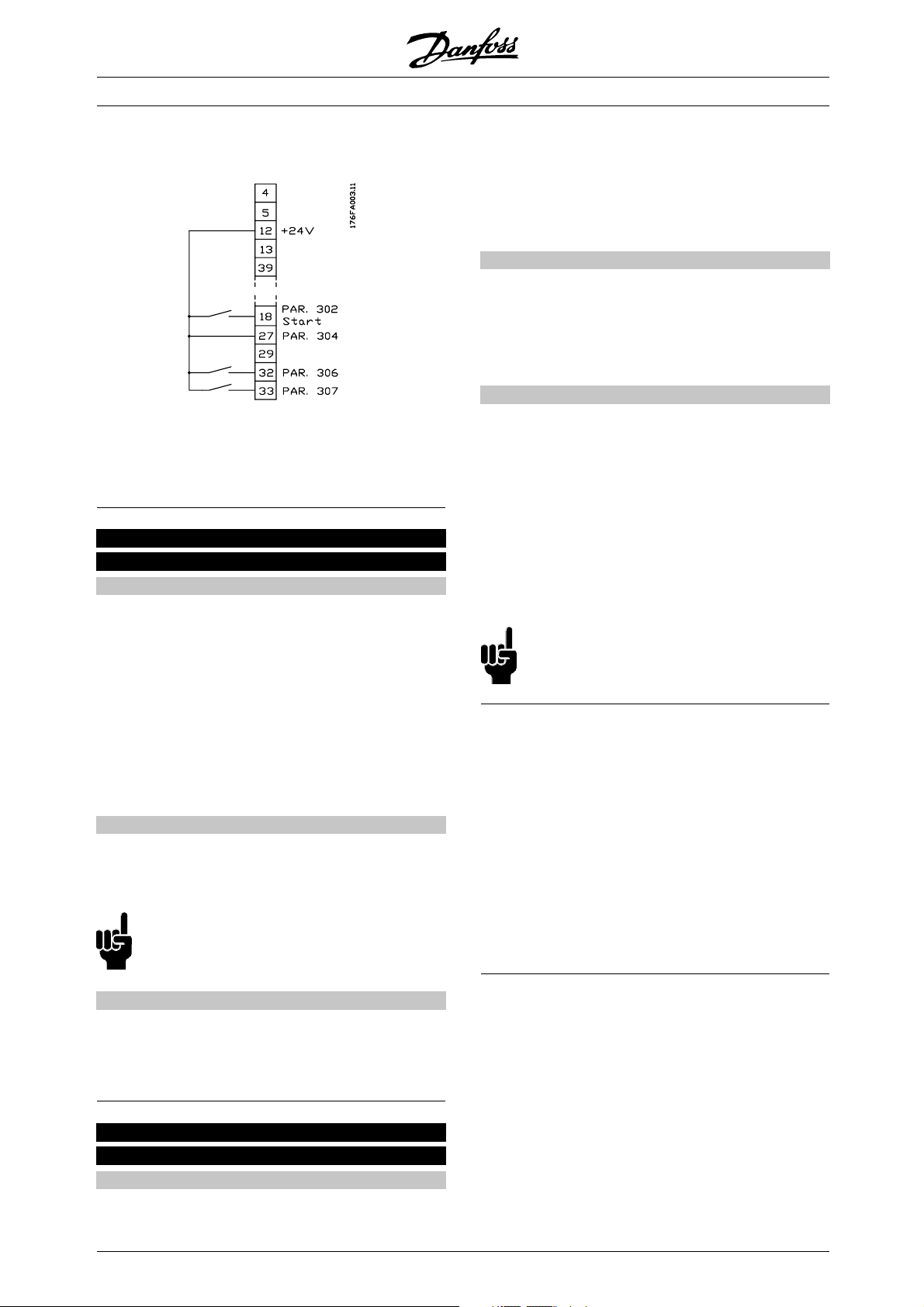
VLT®6000 HVAC Series
Connection examples
Setup change
- Selection of Setup using terminals 32 and 33.
Parameter 306 = Selection of Setup,lsb[4]
Parameter 307 = Selection of Setup,msb[4]
Parameter 002 =MultiSetup [5].
003 Copying of Setups
(SETUP COPY)
Value:
✭No copying (NO COPY)
Copy active Setup to Setup 1
(COPY TO SETUP 1)
Copy active Setup to Setup 2
(COPY TO SETUP 2)
Copy active Setup to Setup 3
(COPY TO SETUP 3)
CopyactiveSetuptoSetup4(COPYTOSETUP4)
Copy active Setup to all
(COPY TO ALL)
Function:
A copy is made from the active Setup selected in
parameter 002 Active Setup to the Setup or Setups
selected in parameter 003 Copying of Setups.
NB!:
Copying is only possible in Stop mode (motor
stopped on a Stop command).
(UPLOAD ALL PARAMET.)
Download all parameters
(DOWNLOAD ALL PARAM.)
Download power-independent par.
(DOWNLOAD SIZE INDEP.)
Function:
Parameter 004 LCP copy is used if the integrated
copying function of the control panel is to be used.
This function is used if all parameter Setups are
to be copied from one frequency converter to
another by moving the control panel.
Description of choice:
Select Upload all parameters [1] if all parameter values
aretobetransmittedtothecontrolpanel.
Select Download all parameters [2] if all transmitted
parameter values are to be copied to the frequency
converter on whichthe control panel has been mounted.
Select Download power-independent par. [3] if only the
power-independent parameters are to be downloaded.
This is used if downloading to a frequency converter
that has a different rated power than the one from
[0]
[1]
[2]
[3]
[4]
[5]
where the parameter Setup originates.
NB!:
Uploading/Downloading can only be carried
out in the Stop mode.
■Setup of user-defined readout
Parameter 005 Max. value of user-defined readout
and 006 Unit for user-defined readout allow users
to design their own readout which can be seen
if user-defined readout has been selected under
display readout. The range is set in parameter 005
Max. value of user-defined readout and the unit is
determined in parameter 006 Unit for user-defined
readout. The choice of unit decides whether the
ratio between the output frequency and the readout
is a linear, square or cubed ratio.
[1]
[2]
[3]
Description of choice:
The copying starts when the required copying function
has been selected and the [OK] key has been pressed.
The display indicates when copying is in progress.
004 LCP copy
(LCP COPY)
Value:
✭No copying (NO COPY)
Upload all parameters
✭ = factory setting. () = display text [] = value for use in communication via serial communication port
80
[0]
MG.61.A5.02 - VLT is a registered Danfoss trademark
Page 81

VLT®6000 HVAC Series
005 Max. value of user-defined readout
Function:
(CUSTOM READOUT)
Value:
0.01 - 999,999.99
✭ 100.00
Function:
This parameter allows a choice of the max. value
of the user-defined readout. The value is calculated
on the basis of the present motor frequency and the
unit selected in parameter 006 Unit for user-defined
readout. The programmed value is reached when
the output frequency in parameter 202 Output
frequency high limit,f
is reached. The unit also
MAX
decides whether the ratio between output frequency
and readout is linear, square or cubed.
Description of choice:
Set the required value for max. output frequency.
Select a unit to be shown in the display in connection
with parameter 005 Max. value of user-defined readout.
006 Unit for user-defined readout
(CUST. READ. UNIT)
✭No unit
1
%
1
rpm
1
ppm
pulse/s
1
l/s
1
l/min
1
l/h
1
kg/s
kg/min
1
kg/h
3/s1
m
3
/min
m
3/h1
m
1
m/s
2
mbar
2
bar
2
Pa
2
kPa
2
MWG
3
kW
1
[0] GPM
[1] gal/s
[2] gal/min
1
[3] gal/h
[4] lb/s
[5] lb/min
[6] lb/h
[7] CFM
1
[8] ft3/s
[9] ft3/min
[10] ft3/h
1
[11] ft3/min
[12] ft/s
[13] in wg
[14] ft wg
[15] PSI
[16] lb/in
[17] HP
[18]
[19]
[20]
1
1
1
1
1
1
1
1
1
1
1
1
1
2
2
2
2
3
Flow and speed units are marked with 1.
Pressure units with 2, and power units with
3. Seefigureinnextcolumn.
[21]
[22]
[23]
[24]
[25]
[26]
[27]
[28]
[29]
[30]
[31]
[32]
[33]
[34]
[35]
[36]
[37]
[38]
If units such as flow or speed units are selected, the
ratio between readout and output frequency
will be a linear one.
If pressure units are selected (bar, Pa, MWG, PSI,
etc.), the ratio will be square. If power units (HP,
kW) are selected, the ratio will be cubed.
The value and the unit are shown in display mode
whenever User-defined readout [10] has been selected
in one of parameters 007-010 Display readout.
Description of choice:
Select the required unit for User-defined readout.
007 Large display readout
(LARGE READOUT)
Value:
Resulting reference [%] (REFERENCE [%])
Resulting reference [unit] (REFERENCE [UNIT])
✭Frequency [Hz] (FREQUENCY [HZ])
% of maximum output frequency [%]
(FREQUENCY [%])
Motor current [A] (MOTOR CURRENT [A])
Power [kW] (POWER [KW])
Power [HP] (POWER [HP])
Output energy [kWh] (ENERGI [UNIT])
Hours run [Hours] (OURS RUN [H])
User-defined readout [-]
(CUSTOM READ.[UNITS]))
Setpoint 1 [unit] (SETPOINT 1 [UNITS])
Setpoint 2 [unit] (SETPOINT 2 [UNITS])
Feedback 1 (FEEDBACK 1 [UNITS])
Feedback 2 (FEEDBACK 2 [UNITS])
= factory setting. () = display text [] = value for use in communication via serial communication port
✭
Programming
[1]
[2]
[3]
[4]
[5]
[6]
[7]
[8]
[9]
[10]
[11]
[12]
[13]
[14]
MG.61.A5.02 - VLT is a registered Danfoss trademark
81
Page 82

VLT®6000 HVAC Series
Feedback [unit] (FEEDBACK [UNITS])
Motor voltage [V] (MOTOR VOLTAGE [V])
DC link voltage [V] (DC VOLTAGE [V])
[15]
[16]
[17]
Thermal load, motor [%]
(THERM.MOTOR LOAD [%])
[18]
Thermal load, VLT [%]
(THERM.DRIVE LOAD [%])
[19]
Digital input [Binary code]
(DIGITAL INPUT [BIN])
Analogue input 53 [V] (ANALOG INPUT 53 [V])
Analogue input 54 [V] (ANALOG INPUT 54 [V])
[20]
[21]
[22]
Analogue input 60 [mA]
(ANALOG INPUT 60 [MA])
Relay status [binary code] (RELAY STATUS)
Pulse reference [Hz] (PULSE REFERENCE [HZ])
External reference [%] (EXT. REFERENCE [%])
Heat sink temp. [°C] (HEATSINK TEMP [°C])
[23]
[24]
[25]
[26]
[27]
Communication option card warning
(COMM OPT WARN [HEX])
LCP display text (FREE PROG.ARRAY)
Status word (STATUS WORD [HEX])
Control word(CONTROL WORD [HEX])
Alarm word(ALARM WORD [HEX])
PID output [Hz] (PID OUTPUT [HZ])
PID output [%] (PID OUTPUT [%])
Real Time Clock (REAL TIME CLOCK)
[28]
[29]
[30]
[31]
[32]
[33]
[34]
[40]
Function:
This parameter allows a choice of the data value to
be shown in the display, line 2, when the frequency
converter is turned on. The data values will also be
included in the display mode scroll-list. Parameters
008-010 Small display readout allow a choice of
another three data values, shown in line 1.
See the description of the control unit.
Description of choice:
No readout can only be selected in parameters
008-010 Small display readout.
Resulting reference [%] gives a percentage for
the resulting reference in the range from Minimum
reference,Ref
to Maximum reference, Ref
MIN
MAX
.Seealsoreference handling.
Reference [unit] gives the resulting reference in Hz
in Open loop.InClosed loop, the reference unit is
selected in parameter 415 Process units.
Frequency [Hz] gives the output frequency
from the frequency converter.
% of maximum output frequency [%] is the present
output frequency as a percentage value of parameter
202 Output frequency high limit, f
MAX
.
Motor current [A] states the phase current of the
motor measured as effective value.
Power [kW] states the actual power consumed
by the motor in kW.
Power [HP] states the actual power consumed
by the motor in HP.
Output energy [kWh] states the energy consumed
by the motor since the latest reset was made in
pa-rameter 618 Reset of kWh counter.
Hours run [Hours] states the number of hours
that the motor has run since the latest reset in
parameter 619 Reset of hours-run counter.
User -defined readout [-] is a user-defined value,
calculated on the basis of the present output frequency
and unit, as well as the scaling in parameter 005
Max. value of user-defined readout. Select unit in
parameter 006 Unit for user-defined readout.
Setpoint 1 [unit] is the programmed setpoint
value in parameter 418 Setpoint 1. The unit
is decided in parameter 415 Process units .
See also Feedback handling.
Setpoint 2 [unit] is the programmed setpoint value
in parameter 419 Setpoint 2. The unit is decided
in parameter 415 Process units.
Feedback 1 [unit] gives the signal value of the resulting
feedback 1 (Term. 53). The unit is decided in parameter
415 Process units. See also Feedback handling .
Feedback 2 [unit] gives the signal value of the
resulting feedback 2 (Term. 53). The unit is decided
in parameter 415 Process units.
Feedback [unit] gives the resulting signal value
using the unit/scaling selected in parameter 413
Minimum feedback,FB
and 415 Process units .
FB
MAX
, 414 Maximum feedback,
MIN
Motor voltage [V] states the voltage supplied
to the motor.
DC link voltage [V] states the intermediate circuit
voltage in the frequency converter.
Thermal load, motor [%] states the calculated/
estimated thermal load on the motor. 100%
is the cut-out limit. See also parameter 117
Motor thermal protection.
Thermal load, VLT [%] states the calculated/
estimated thermal load on the frequency converter.
100% is the cut-out limit.
Digital input [Binar y code] states the signal status
from the 8 digital inputs (16, 17, 18, 19, 27, 29, 32
and 33). Terminal 16 corresponds to the bit at the far
left. ‘0’ = no signal, ‘1’ = connected signal.
Analogue input 53 [V] states the voltage
value on terminal 53.
Analogue input 54 [V] states the voltage
value on terminal 54.
Analogue input 60 [mA] states the voltage
value on terminal 60.
= factory setting. () = display text [] = value for use in communication via serial communication port
✭
82
MG.61.A5.02 - VLT is a registered Danfoss trademark
Page 83
VLT®6000 HVAC Series
Relay status [binary code] indicates the status of
each relay. The left (most significant) bit indicates
relay 1 followed by 2 and 6 through 9. A "1" indicates
the relay is active, a "0" indicates inactive. Paramater
007 uses an 8-bit word with the last two positions
not used. Relays 6-9 are provided with the cascade
controller and four relay option cards
Pulse reference [Hz] states a pulse frequency in
Hz connected to terminal 17 or terminal 29.
External reference [%] gives the sum of the external
references as a percentage (the sum of analogue/
pulse/serial communication) in the range from Minimum
reference,Ref
to Maximum reference,Ref
MIN
MAX
.
Heat sink temp. [°C] states the present heat sink
temperature of the frequency converter. The cut-out
limit is 90 ± 5°C; cutting back in occurs at 60 ± 5°C.
Communication option card warning [Hex] gives a
warning word if there is a fault on the communication
bus. This is only active if communication options
have been installed. Without communication
options, 0 Hex is displayed.
LCP d isplay text shows the text programmed in
parameter 533 Display text 1 and 534 Display text
2 viaLCPortheserialcommunicationport.
LCP procedure for entering text
After selecting Display Text in parameter 007, select
display line parameter (533 or 534) and press the
CHANGE DATA key. Enter text directly into the
selected line by using UP,DN&LEFT,RIGHTarrow
keys on the LCP. The UP and DN arrow keys scroll
through the available characters. The Left and Right
arrow keys move the cursor through the line of text.
To lock in the text, press the OK key when the line of text
is completed. The CANCEL key will cancel the text.
The available characters are:
ABCDEFGHIJKLMNOPQRSTUVWXYZ
ЖШЕДЦЬЙМЩи./-()0123456789’space’
’space’ is the default value of parameter 533 &
534. To erase a character that has been entered,
it must be replaced with ’space’.
Status word displays the actual drive status
word (see parameter 608).
Control word displays the actual control word
(see parameter 607).
Alarm word displays the actual alarm word.
PID output shows the calculated PID output
in the display in either Hz [33] or percentage
of max frequency [34].
Real time clock
Real time clock can show the current time and
date and weekday. The available digits stipulate
how comprehensive the readout can be. E.g if
only the real time clock readout is used in the top
line (parameter 008, 009 or 010) the following is
shown: WD YYYY/MM/DD/ HH.MM. See table
below for further reference:
Available
digits
Format Ex.
6 hh.mm 11.29
8 WW hh.mm WE 11.29
13 WW YYMMDD hh.mm WE 040811 11.29
20 WW YYYY/MM/DD hh.mm WE 2004/08/11 11.29
008 Small display readout 1.1
(SMALL READOUT 1)
Value:
See parameter 007 Large display readout
✭ Reference [Unit]
Function:
This parameter enables a choice of the first of three data
values to be shown on the display, line 1, position 1.
This is a useful function, i.a. when setting the
PID regulator, in order to see how the process
reacts to a change of reference.
For display read-outs, press the [DISPLAY MODE]
button. Data option LCP display text [29] cannot
be selected with Small display readout.
Description of choice:
There is a choice of 33 different data values, see
parameter 007 Large display readout.
009 Small display readout 1.2
(SMALL READOUT 2)
Value:
See parameter 007 Large display readout
✭Motorcurrent [A]
Function:
See the functional description for parameter 008 Small
display readout.DataoptionLCP display text [29]
cannot be selected with Small display readout.
Description of choice:
There is a choice of 33 different data values, see
parameter 007 Large display readout.
[2]
Programming
[5]
✭ = factory setting. () = display text [] = value for use in communication via serial communication port
MG.61.A5.02 - VLT is a registered Danfoss trademark
83
Page 84
VLT®6000 HVAC Series
010 Small display readout 1.3
(SMALL READOUT 3)
Value:
Se parameter 007 Large display readout
✭Power [kW]
Function:
See the functional description for parameter 008
Small data readout. Data option LCP display text [29]
cannot be selected with Small display readout.
Description of choice:
There is a choice of 33 different data values, see
parameter 007 Large display readout.
011 Unit of local reference
(UNIT OF LOC REF)
Value:
Hz (HZ)
✭% of output frequency range (%) (% OF FMAX)
Function:
This parameter decides the local reference unit.
Description of choice:
Choose the required unit for local reference.
012 Hand start on LCP
(HAND START BTTN)
Value:
Disable (DISABLE)
✭Enable (ENABLE)
Function:
This parameter allows selection/deselection of the
Hand start key on the control panel.
Description of choice:
If Disable [0] is selected in this parameter, the
[HAND START] key will be inactive.
013 OFF/STOP on LCP
(STOP BUTTON)
Value:
Disable (DISABLE)
✭Enable (ENABLE)
Function:
This parameter allows selection/deselection of the
local stop key on the control panel.
[6]
[0]
[1]
[0]
[1]
[0]
[1]
Description of choice:
If Disable [0] is selected in this parameter, the
[OFF/ STOP] key will be inactive.
NB!:
If Disable is selected, the motor cannot be
stopped by means of the [OFF/STOP] key.
014 Auto start on LCP
(AUTO START BTTN)
Value:
Disable (DISABLE)
✭Enable (ENABLE)
Function:
This parameter allows selection/deselection of the
auto start key on the control panel.
Description of choice:
If Disable [0] is selected in this parameter, the
[AUTO START] key will be inactive.
015 Reset on LCP
(RESET BUTTON)
Value:
Disable (DISABLE)
✭Enable (ENABLE)
Function:
This parameter allows selection/deselection of the
reset key on the control panel.
Description of choice:
If Disable [0] is selected in this parameter, the
[RESET] key will be inactive.
NB!:
Only select Disable [0] if an external reset signal
has been connected via the digital inputs.
016 Lock for data change
(DATA CHANGE LOCK)
Value:
✭Not locked (NOT LOCKED)
Locked (LOCKED)
Function:
This parameter allows the control panel to be "locked",
which means that it is not possible to carry out
data modifications via the control unit.
[0]
[1]
[0]
[1]
[0]
[1]
✭
= factory setting. () = display text [] = value for use in communication via serial communication port
84
MG.61.A5.02 - VLT is a registered Danfoss trademark
Page 85
Description of choice:
If Locked [1] is selected, data modifications in the
parameters cannot be made, although it will still
be possible to carry out data modifications via the
bus. Parameters 007-010 Display readout can
be changed via the control panel.
It is also possible to lock for data modifications in
these parameters by means of a digital input, see
parameters 300-307 Digital inputs.
017 Operating state at power up, local control
(POWER UP ACTION)
Value:
✭Auto restart (AUTO RESTART)
OFF/Stop (OFF/STOP)
Function:
Setting of the desired operating mode when the
mains voltage is reconnected.
VLT®6000 HVAC Series
[0]
[1]
Description of choice:
Auto restart [0] is selected if the frequency converter is to
start up in the same start/stop condition as immediately
before power to the frequency converter is cut off.
OFF/Stop [1] is selected if the frequency converter
is to remain stopped when the mains voltage is
connected, until a start command is active. To
restart, activate the key [HAND START] or [AUTO
START] b
start on LCP) themotorwillnotbeableto
restart if OFF/Stop [1] is selected. If Handstart
or Autostart has been programmed for activation
via the digital inputs, the motor will not be able
to restart if OFF/Stop [1] is selected.
y using the control panel.
NB!:
If [HAND START] or [AUTO START] cannot
be activated by the keys on the control
panel (see parameter 012/014 Hand/Auto
Programming
✭ = factory setting. () = display text [] = value for use in communication via serial communication port
MG.61.A5.02 - VLT is a registered Danfoss trademark
85
Page 86
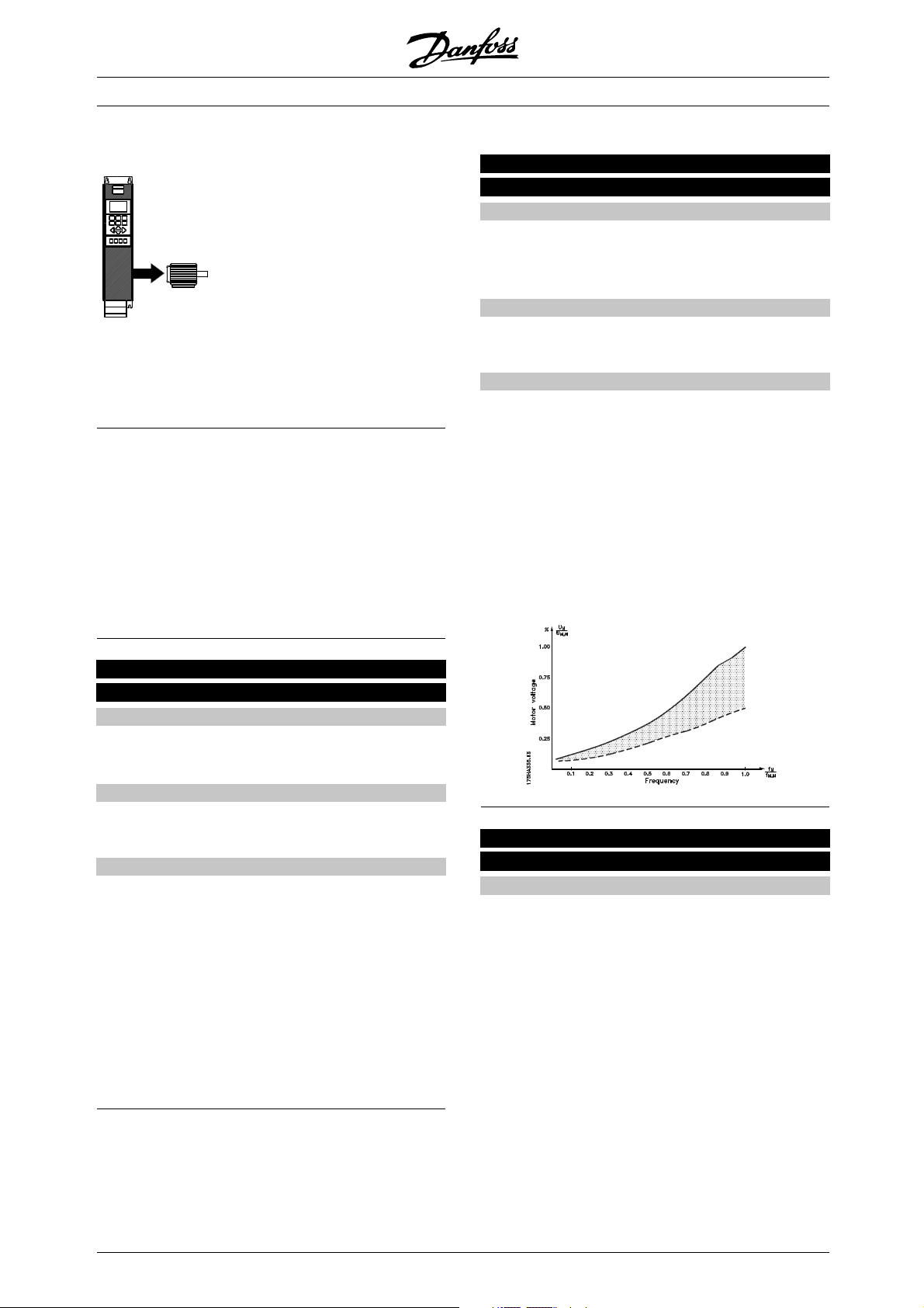
■Load and Motor 100-117
This parameter group allows
the con-figuration of regulation
parameters and the choice of
torque characteristics to which
the frequency converter is to be
adapted.
Themotornameplatedatamust
be
set and automatic motor adaptation can be carried
out. In addition, DC brake parameters can be set
and the motor thermal protection can be activated.
■Configuration
The selection of configurati
influences the parameters that can be seen in the
display. If Open loop [0] is selected, all parameters
relating to PID regul
Consequently, the user is only able to see
the parameters that are of significance for
a given applicatio
n.
on and torque characteristics
ation will be hidden.
VLT®6000 HVAC Series
101 Torque characteristics
(VT CHARACT)
Value:
✭Automatic Energy Optimisation
(AEO FUNCTION)
Parallel motors (MULTIPLE MOTORS)
Function:
This parameterallows a choice ofwhether the frequency
converter has one or several motors connected to it.
Description of choice:
If Automatic Energy Optimisation [0] has been selected,
only one motor may be connected to the frequency
converter. The AEO function ensures that the motor
obtains its maximum efficiency and minimises motor
interference. Parameter 118 makes it possible to set the
powerfactor(Cosϕ) which is used by the AEO function.
Select Parallel motors [1] if more than one motor is
connected to the output in parallel. See the description
under parameter 108 Start voltage of parallel motors
regarding the setting of parallel motor start voltages.
[0]
[1]
100 Configurati
(CONFIG. MODE)
Value:
✭Open loop (OPEN LOOP)
Closed loop (CLOSED LOOP)
Function:
This parameter is used for selecting the configuration
to which the frequency converter is to be adapted.
Description of choice:
If Open loop [0] is selected, normal speed control is
obtained (withou
is changed, the motor speed will change.
If Closed loop [1] is selected, the internal process
regulator is ac
in relation to a given process signal.
The reference (setpoint) and the process signal
(feedback) ca
programmed in parameter 415 Process units.
See Feedback handling.
on
t feedback signal), i.e. if the reference
tivated to enable accurate regulation
n be set to a process unit as
[0]
[1]
102 Motor power, P
(MOTOR POWER)
Value:
0.25 kW (0.25 KW)
0.37 kW (0.37 KW)
0.55 kW (0.55 KW)
0.75 kW (0.75 KW)
1.1 kW (1.10 KW)
1.5 kW (1.50 KW)
2.2 kW (2.20 KW)
3 kW (3.00 KW)
4 kW (4.00 KW)
5,5 kW (5.50 KW)
7,5 kW (7.50 KW)
11 kW (11.00 KW)
15 kW (15.00 KW)
18.5 kW (18.50 KW)
22 kW (22.00 KW)
30 kW] (30.00 KW)
M,N
[25]
[37]
[55]
[75]
[110]
[150]
[220]
[300]
[400]
[550]
[750]
[1100]
[1500]
[1850]
[2200]
[3000]
= factory setting. () = display text [] = value for use in communication via serial communication port
✭
86
MG.61.A5.02 - VLT is a registered Danfoss trademark
Page 87
VLT®6000 HVAC Series
37 kW (37.00 KW)
45 kW (45.00 KW)
55 kW (55.00 KW)
75 kW (75.00 KW)
90 kW (90.00 KW)
110 kW] (110.00 KW)
132 kW (132.00 KW)
160 kW (160.00 KW)
200 kW (200.00 KW)
250 kW (250.00 KW)
300 kW (300.00 KW)
315 kW (315.00 KW)
355 kW (355.00 KW)
400 kW (400.00 KW)
450 kW (450.00 KW)
500 kW (500.00 KW)
550 kW (550.00 KW)
[3700]
[4500]
[5500]
[7500]
[9000]
[11000]
[13200]
[16000]
[20000]
[25000]
[30000]
[31500]
[35500]
[40000]
[45000]
[50000]
[55000]
✭Depends on the unit
Function:
This is where to select the kW value P
M,N
that
corresponds to the rated power of the motor. At the
works, a rated kW value P
has been selected
M,N
that depends on the type of unit.
Description of choice:
Select a value that equals the nameplate data on the
motor. There are 4 possible undersizes or 1 oversize in
comparison with the factory setting. Also, alternatively
it is possible to set the value for motor power as an
nfinitely variable value, see the procedure for Infinitely
i
variable change of numeric data value .
103 Motor voltage, U
M,N
(MOTOR VOLTAGE)
Value:
200 V
208 V
220 V
230 V
240 V
380 V
400 V
415 V
440 V
460 V
480 V
500 V
550 V
575 V
600 V
[200]
[208]
[220]
[230]
[240]
[380]
[400]
[415]
[440]
[460]
[480]
[500]
[550]
[575]
[600]
✭Depends on the unit
Function:
This is where the rated motor voltage U
set for either star Y or delta
.
M,N
is
Description of choice:
Select a value that equals the nameplate data on
the motor, regardless of the mains voltage of the
frequency converter. Furthermore, alternatively it is
possible to set the value of the motor voltage i
nfinitely
variably. Also refer to the procedure for infinitely
variable change of numeric data value.
NB!:
Changing parameters 102, 103 or 104 will
automatically reset parameters 105 and 106
to default values. If changes are made to
parameters 102, 103 or 104, go back and reset
parameters 105 and 106 to correct values.
104 Motor frequency, f
M,N
(MOTOR FREQUENCY)
Value:
✭50 Hz (50 HZ)
60 Hz (60 HZ)
[50]
[60]
Function:
This is where the rated motor frequency f
is selected.
M,N
Description of choice:
Select a value that equals the nameplate data
on the motor. Furthermore, it is also possible
to set the value for motor frequency i
nfinitely
variably in the 24-1000 Hz range.
105 Motor current, I
(MOTOR CURRENT)
M,N
(MOTOR CURRENT)
Value:
0.01 - I
VLT,MAX
A
✭ Depends on the unit
Function:
The rated motor current I
forms part of the frequency
M,N
converter calculations i.a. of torque and motor thermal
protection. Set the motor current I
,takinginto
VLT,N
account the star Y or delta connected motor.
Description of choice:
Set a value that equals the nameplatedata on the motor.
Programming
= factory setting. () = display text [] = value for use in communication via serial communication port
✭
MG.61.A5.02 - VLT is a registered Danfoss trademark
87
Page 88
VLT®6000 HVAC Series
NB!:
It is important to enter the correct value, since
+
this forms part of the VVC
106 Rated motor speed, n
control feature.
M,N
(MOTOR NOM. SPEED)
Value:
100 - f
✭Depends on parameter 102 Motor power, P
x 60 (max. 60000 rpm)
M,N
M,N
Function:
This is where the value is set that corresponds
to the rated motor speed n
, which can be
M,N
seen from the nameplate data.
Description of choice:
Choose a value that corresponds to the
motor nameplate data.
NB!:
It is important to set the correct value, since
+
this forms part of the VVC
The max. value equals f
is set in parameter 104 Motor frequency, f
f
M,N
control feature.
x 60.
M,N
M,N
.
107 Automatic motor adaptation, AMA
(AUTO M OTOR ADAPT)
Value:
✭Optimisation disable (NO AMA)
Automatic adaptation (RUN AMA)
Automatic adaptation with LC-filter
(RUN AMA WITH LC-FILT)
Function:
Automatic motor adaptation is a test algorithm
that measures the electrical motor parameters
at motor standstill. This means that AMA itself
does not supply any torque.
AMA is useful when commissioning systems, where
the user wants to optimise the adjustment of the
frequency converter to the motor applied. This feature
is used in particular where the factory setting does
not adequately cover the motor in question.
For the best adjustment of the frequency converter, it is
recommended to carry out AMA on a cold motor.
It must be noted that repeated AMA runs may
lead to a heating of the motor that will result in
an increase of the stator resistance R
.However,
S
this is not normally critical.
[0]
[1]
[2]
NB!:
It is important to run AMA with any
motors ≥55 kW/ 75 HP
It is possible via parameter 107 Automatic motor
adaptation, AMA to choose whether a complete
automatic motor adaptation Automatic adaptation
[1] is to be carried out, or whether reduced
automatic motor adaptation Automatic adaptation
with LC-filter [2] is to be made.
It is only possible to carry out the reduced test if a
LC-filter has been placed between the frequency
converter and the motor. If a total setting is required, the
LC-filter can be removed and, after completion of the
AMA, it can be reinstalled. In Automatic optimisation
with LC-filter [2] there is no test of motor symmetry and
of whether all motor phases have been connected. The
following must be noted when the AMA function is used:
- ForAMAtobeabletodeterminethemotor
parameters optimally, the correct nameplate data
for the motor connected to the frequency converter
must be entered in parameters 102 to 106.
- The duration of a total automatic motor adaptation
varies from a few minutes to approx. 10 minutes
for small motors, depending on the rating of
the motor used (the time for a 7.5 kW motor,
for example, is approx. 4 minutes).
- Alarms and warnings will be shown in the display
if faults occur during motor adaptation.
- AMA can only be carried out if the rated motor
current of the motor is min. 35% of the rated
output current of the frequency converter.
- If automatic motor adaptation is to be discontinued,
press the [OFF/STOP] key.
NB!:
AMA is not allowed on motors connected
in parallel.
Description of choice:
Select Automatic adaptation [1] if the frequency
converter is to carry out a complete aut
omatic
motor adaptation.
Select Automatic adaptation with LC-filter [2] if a
LC-filter has been placed between the f
requency
converter and the motor.
Procedure for automatic motor adaptation:
1. Set the motor parameters in accordance with
themotornameplatedatagiveninparameters
102-106 Nameplate data.
= factory setting. () = display text [] = value for use in communication via serial communication port
✭
88
MG.61.A5.02 - VLT is a registered Danfoss trademark
Page 89
VLT®6000 HVAC Series
2. Connect 24 V DC (possibly from terminal 12)
to terminal 27 on the control card.
3. Select Automatic adaptation [1] or Automatic
adaptation with LC-filter [2] in parameter 107
Automatic motor adaptation, AMA.
4. Start up the frequency converter or connect terminal
18 (start) to 24 V DC (possibly from terminal 12).
5. After a normal sequence, the display reads: AMA
STOP. After a reset, the frequency converter will
be ready to start operation again.
If the automatic motor adaptation is to be stopped:
1. Press the [OFF/STOP] key.
If there is a fault, the display reads: ALARM 22
1. Press the [Reset] key.
2. Check for possible causes of the fault in
accor-dance with the alarm message. See
List of warnings and alarms.
If there is a warning, the display reads:
WARNING 39-42
1. Check for possible causes of the fault in accordance
with the warning. See List of warnings and alarms.
2. Press the [CHANGE DATA] key and select
"Continue" if AMA is to continue despite the
warning, or press the [OFF/STOP] key to stop
the automatic motor adaptation.
108 Start voltage of parallel motors
(MULTIM.START VOLT)
Value:
0.0 - parameter 103 Motor voltage, U
✭ Depends on par. 103 Motor voltage, U
M,N
M,N
Function:
This parameter specifies the start-up voltage of
the permanent VT characteristics at 0 Hz for
motors connected in parallel.
The start-up voltage represents a supplementary
voltage input to the motor. By increasing the start-up
voltage, motors connected in parallel receive a higher
start-up torque. This is used especially for small motors
(< 4.0 kW) connected in parallel, as they have a higher
stator resistance than motors above 5.5 kW.
This function is only active if Parallel motors [1] has
been selected in parameter 101 Torque characteristics .
109 Resonance damping
(RESONANCE DAMP.)
Value:
0-500%
✭ 100 %
Function:
High-frequency electric resonance problems between
the frequency converter and the motor can be
eliminated by adjusting the resonance damping.
Description of choice:
Adjust the damping percentage until the motor
resonance has disappeared.
110 High break-away torque
(HIGH START TORQ.)
Value:
0.0 (OFF) - 0.5 sec.
✭ OFF
Function:
In order to secure a high starting torque, the maximum
torque for max. 0.5 sec. is allowed. However,
the current is limited by the protection limit of the
frequency converter (inverter). 0 sec. corresponds
to no high break-away torque.
Description of choice:
Set the necessary time in which a high starting
torque is desired.
111 Start delay
(START DELAY)
Value:
0.0 - 120.0 sec.
✭ 0.0 sec.
Function:
This parameter enables a delay of the starting time
after the conditions for start have been fulfilled.
When the time has passed, the output frequency
will start by ramping up to the reference.
Description of choice:
Set the desired time until acceleration is to begin.
Programming
Description of choice:
Set the start-up voltage at 0 Hz. The maximum voltage
depends on parameter 103 Motor voltage,U
M,N
.
112 Motor preheater
(MOTOR PREHEAT)
Value:
✭Disable (DISABLE)
Enable (ENABLE)
✭
= factory setting. () = display text [] = value for use in communication via serial communication port
MG.61.A5.02 - VLT is a registered Danfoss trademark
[0]
[1]
89
Page 90

VLT®6000 HVAC Series
Function:
The motor preheater ensures that no condensate
develops in the motor at stop. This function can also
be used to evaporate condensed water in the motor.
The motor preheater is only active during stop.
Description of choice:
Select Disable [0] if this function is not required. Select
Enable [1] to activate motor preheating. The DC current
is set in parameter 113 Motor preheater DC current.
113 Motor preheater DC current
(PREHEAT DC-CURR.)
Value:
0 - 100 %
✭ 50 %
The maximum value depends on the rated motor
current, parameter 105 Motor current, I
M,N
.
Function:
The motor can be preheated at stop by means of a DC
current to prevent moisture from entering the motor.
VLT 6152-6602, 380-460 V and VLT 6102-6652,
525-600 V work with a reduced DC current. The level
can, depending on motor selection, be down to 80%.
Description of choice:
The motor can be preheated by means of a DC
current. At 0%, the function is inactive; at a value
higher than 0%, a DC current will be supplied to
the motor at stop (0 Hz). This function can also
be used to generate a holding torque.
If too high a DC current is supplied for too
long, the motor can be damaged.
■DC braking
In DC braking, the motor receives a DC current
that brings the shaft to a halt. Parameter 114 DC
braking current, decides the DC braking current as
a percentage of the rated motor current I
M,N
.
In parameter 115 DC braking time,theDCbraking
time is selected, and in parameter 116DC brake
cut-in frequency, the frequency is selected at
which DC braking becomes active.
If terminal 19 or 27 (parameter 303/304Digital input)has
been programmed to DC braking inverse and shifts from
logic "1" to logic "0", the DC braking will be activated.
When the start signal on terminal 18 changes
from logic "1" to logic "0", the DC braking will be
activated when the output frequency becomes lower
than the brake coupling frequency.
NB!:
TheDCbrakeisnottobeusediftheinertia
of the motor shaft is more than 20 times
the inertia of the motor itself.
114 DC braking current
(DC BRAKE CURRENT)
Value:
✭ 50 %
The maximum value depends on the rated
motor current. If the DC braking current is
active, the frequency converter has a switching
frequency of 4 kHz.
Function:
This parameter is used for setting the DC braking
current that is activated upon a stop when the DC
brake frequency set in parameter 116, DC brake
cut-in frequency has been reached, or if DC brake
inverse is active via terminal 27 or via the serial
communication port. The DC braking current will
be active for the duration of the DC braking time
set in parameter 115 DC braking time.
VLT 6152-6602, 380-460 V and VLT 6102-6652,
525-600 V work with a reduced DC current. The level
can, depending on motor selection, be down to 80%.
Description of choice:
To be set as a percentage value of the rated motor
current I
100% DC braking current corresponds to I
set in parameter 105 Motor current, I
M,N
M,N
VLT,N
.
Make sure not to supply too high a braking
current for too long.The motor will be
damaged because of mechanical overload
or the heat generated in the motor.
115 DC braking time
(DC BRAKE TIME)
Value:
0.0 - 60.0 sec.
✭ 10 sec.
Function:
This parameter is for setting the DC braking time
for which the DC braking current (parameter
113) is to be active.
Description of choice:
Set the desired time.
.
✭ = factory setting. () = display text [] = value for use in communication via serial communication port
90
MG.61.A5.02 - VLT is a registered Danfoss trademark
Page 91

VLT®6000 HVAC Series
116 DC brake cut-in frequency
(DC BRAKE CUT-IN)
Value:
0.0 (OFF) - par. 202
Output frequency high limit, f
MAX
✭ OFF
Function:
This parameter is used for setting the DC brake cut-in
frequency at which DC braking is to be activated
Select Thermistor trip [2] if cutting out (trip) is desired
when the connected thermistor overheats.
Select ETR Warning 1-4,ifawarningistocome
up on the display when the motor is overloaded
according to the calculations.
The frequency converter can also be programmed to
give off a warning signal via one of the digital outputs.
Select ETR Trip 1-4 if tripping is desired when the
motor is overloaded according to the calculations.
in connection with a stop command.
Description of choice:
Set the desired frequency.
117 Motor thermal protection
(MOT. THERM PROTEC)
Value:
No protection(NO PROTECTION)
Thermistor warning (THERMISTOR WARNING)
Thermistor trip (THERMISTOR FAULT)
ETR Warning 1 (ETR WARNING 1)
✭ETR Trip 1(ETR TRIP 1)
ETR Warning 2 (ETR WARNING 2)
ETR Trip 2(ETR TRIP 2)
ETR Warning 3 (ETR WARNING 3)
ETR Trip 3(ETR TRIP 3)
ETR Warning 4 (ETR WARNING 4)
ETR Trip 4(ETR TRIP 4)
[0]
[1]
[2]
[3]
[4]
[5]
[6]
[7]
[8]
[9]
[10]
NB!:
In UL / cUL applications ETR provides class
20 motor overload profection in accordance
with National Electrical Code.
118 Motor power factor (Cos ϕ)
Function:
The frequency converter is able to monitor the motor
temperature in two different ways:
- Via a thermistor sensor fitted to the motor. The
thermistor is connected to one of the analog
input terminals 53 and 54.
- Calculation of the thermal load (ETR - Electronic
(MOTOR PWR FACT)
Value:
0.50 - 0.99
Function:
This parameter calibrates and optimizes the AEO
function for motors of different power factor (Cos ϕ).
Thermal Relay), based on the current load and
the time. This is compared with the rated motor
current I
and the rated motor frequency f
M,N
M,N
The calculations made take into account the
need for a lower load at lower speeds because
of less cooling in the motor itself.
.
Description of choice:
Motors having > 4 poles have a lower power factor
which would restrict or prevent use of the AEO function
for energy savings. This parameter allows the user
to calibrate the AEO function to the power factor of
the motor so that AEO can be used with motors of
ETR functions 1-4 do not start calculating the load until
6, 8, and 12 poles as well as 4 and 2 poles.
there is a switch-over to the Setup in which they were
selected. This enables the use of the ETR function,
even where two or several motors alternate.
NB!:
The default value is 0.75 and should
be changed unless the specific motor
Description of choice:
Select No protection [0] if no warning or tripping is
required when the motor is overloaded.
has power factor lower than 0.75. This
is typically the case for motors having more than
4 poles or low efficiency motors.
Select Thermistor warning [1] if a warning is desired
when the connected thermistor gets too hot.
✭ = factory setting. () = display text [] = value for use in communication via serial communication port
Programming
✭ 0.75
NOT
MG.61.A5.02 - VLT is a registered Danfoss trademark
91
Page 92

VLT®6000 HVAC Series
■References and Limits 200-228
In this parameter group, the frequency and reference
range of the frequency converter are established.
This parameter group also includes:
- Setting of ramp times
- Choice of four preset references
- Possibility of programming four bypass frequencies.
- Setting of maximum current to motor.
- Setting of warning limits for current, frequency,
reference and feedback.
202 Output frequency high limit, f
MAX
(MAX. FREQUENCY)
Value:
f
- 120/1000 Hz
MIN
(par. 200 Output frequency range)
✭ 50 Hz
Function:
In this parameter, a maximum output frequency
can be selected that corresponds to the highest
speed at which the motor can be.
NB!:
The output frequency of the frequency
converter can never assume a value higher
than 1/10 of the switching frequency
(parameter 407 Switching frequency.
Description of choice:
Avaluefromf
tothechoicemadeinparameter
MIN
200 Output frequency range can be selected.
200 Output frequency rang e
(FREQUENCY RANGE)
Value:
✭0 - 120 Hz (0 - 120 HZ)
0 - 1000 Hz (0 - 1000 HZ)
Function:
This is where to select the maximum output
frequency range to be set in parameter 202
Output frequency high limit,f
MAX
.
Description of choice:
Select the required output frequency range.
201 Output frequency low limit, f
MIN
(MIN. FREQUENCY)
Value:
0.0 - f
MAX
✭ 0.0 HZ
Function:
This is where to select the minimum output frequency.
[0]
[1]
Description of choice:
A value from 0.0 Hz to the Output frequency high limit,
frequency set in parameter 202 can be selected.
f
MAX
✭ = factory setting. () = display text [] = value for use in communication via serial communication port
92
MG.61.A5.02 - VLT is a registered Danfoss trademark
Page 93

■Reference handling
Reference handling is shown in the block
diagram underneath.
The block diagram shows how a change in a parameter
can affect the resulting reference.
Parameters 203 to 205 Reference handling, minimum
and maximum reference and parameter 210 Reference
type define the way reference handling can be
carried out. The mentioned parameters are active
both in a closed and in an open loop.
Remote references are defined as:
• External references, such as analog inputs 53, 54
and 60, pulse reference via terminal 17/29 and
reference from serial communication.
• Preset references.
The resulting reference can be shown in the display
by selecting Reference [%] in parameters 007-010
Display readout and in the form of a unit by selecting
Resulting reference [unit]. See the section on Feedback
handling in connection with a closed loop.
VLT®6000 HVAC Series
The sum of the external references can be shown
in the display as a percentage of the range from
Minimum reference, Ref
. Select External reference, % [25] in parameters
MAX
007-010 Display readout if a readout is required.
It is possible to have both preset references and
external references at the same time. In parameter 210
Reference type a choice is made of how the preset
references are to be added to the external references.
Furthermore, an independent local reference exists,
where the resulting reference is set by means of
the [+/-] keys. If local reference has been selected,
the output frequency range is limited by parameter
201 Output frequency low limit, f
202 Output frequency high limit, f
NB!:
If the local reference is active, the frequency
converter will a
[0],regardlessofthechoicemadein
parameter 100 Configuration.
to Maximum reference, Ref
MIN
and parameter
MIN
.
MAX
lways be in Open loop
The unit of the local reference can be set either as Hz
or as a percentage of the output frequency range. The
unit is selected in parameter 011 Unit of local reference.
Programming
✭ = factory setting. () = display text [] = value for use in communication via serial communication port
MG.61.A5.02 - VLT is a registered Danfoss trademark
93
Page 94

VLT®6000 HVAC Series
203 Reference site
(REFERENCE SITE)
Value:
✭Hand/Auto linked reference
(LINKED TO HAND/AUTO)
Remote reference(REMOTE)
Local reference (LOCAL)
Function:
This parameter determines the location of the active
reference. If Hand/Auto linked reference [0] is selected,
the resulting reference will depend on whether the
frequency converter is in Hand or Auto mode.
The table shows which references are active when
Hand/Auto linked reference [0], Remote reference [1] or
Local reference [2] has been selected. The Hand mode
or Auto mode can be selected via the control keys or
via a digital input, parameters 300-307 Digital inputs.
Reference
handling Hand mode Auto mode
Hand/Auto [0] Local ref. active Remote ref. active
Remote [1] Remote ref. active Remote ref. active
Local [2] Local ref. active Local ref. active
Description of choice:
If Hand/Auto linked reference [0] is chose
n, the motor
speed in Hand mode will be decided by the local
reference, while in Auto mode it depends on remote
references and any setpoints selecte
d.
If Remote reference [1] is selected, the motor speed will
depend on remote references, regardless of whether
Hand mode or Auto mode has been cho
sen.
If Local reference [2] is selected, the motor speed
will only depend on the local reference set via the
control panel, regardless of wh
ether Hand mode
or Auto mode has been selected.
[0]
[1]
[2]
Minimum reference is ignored when the local reference
is active (parameter 203 Reference site). The unit for
the reference can be seen from the following table:
Unit
Par. 100 Configuration = Open loop Hz
Par. 100 Configuration = Closed loop Par. 415
Description of choice:
Minimum reference is set if the motor is to run
at a minimum speed, regardless of whether
the resulting reference is 0.
205 Maximum reference, Ref
MAX
(MAX. REFERENCE)
Value:
Parameter 100 Configuration = Open loop [0]
Parameter 204 Ref
- 1000.000 Hz
MIN
✭ 50.000 Hz
Parameter 100 Configuration = Closed loop [1]
Par. 204 Ref
- par. 414 Maximum feedback
MIN
✭ 50.000 Hz
Function:
The Maximum reference gives the maximum value
that can be assumed by the sum of all references.
If Closed loop [1] has been selected in parameter
100 Configuration, the maximum reference cannot be
set above parameter 414 Maximum feedback .The
Maximum reference is ignored when the local reference
is active (parameter 203 Reference site ).
The reference unit can be determined on the
basis of the following table:
Unit
Par. 100 Configuration = Open loop Hz
Par. 100 Configuration = Closed loop Par. 415
204 Minimum reference, Ref
MIN
(MIN. REFERENCE)
Value:
Parameter 100 Configuration = Open loop [0].
0.000 - parameter 205 Ref
MAX
✭ 0.000 Hz
Description of choice:
Maximum reference is set if the motor speed is not
to exceed the set value, regardless of whether the
resulting reference is higher than Maximum reference.
Parameter 100 Configuration = Closed loop [1].
-Par. 413 Minimum feedback
- par. 205 Ref
MAX
✭ 0.000
Function:
The Minimum reference gives the minimum value
that can be assumed by the sum of all references.
If Closed loop has been selected in parameter 100
Configuration, the minimum reference is limited by
206 Ramp-up time
(RAMP UP TIME)
Value:
1 - 3600 sec.
Function:
The ramp-up time is the acceleration time from 0
Hz to the rated motor frequency f
parameter 413 Minimum feedback.
= factory setting. () = display text [] = value for use in communication via serial communication port
✭
94
MG.61.A5.02 - VLT is a registered Danfoss trademark
✭ Depends on the unit
(parameter
M,N
Page 95

VLT®6000 HVAC Series
104 Motor frequency, f
). It is assumed that the
M,N
output current does not reach the current limit (set
in parameter 215 Current limit I
LIM
).
Description of choice:
Program the desired ramp-up time.
207 Ramp-down time
(RAMP DOWN TIME)
Value:
1 - 3600 sec.
✭ Depends on the unit
Function:
The ramp-down time is the deceleration time
from the rated motor frequency f
104 Motor frequency, f
)to0Hz,provided
M,N
(parameter
M,N
there is no overvoltage in the inverter because of
the motor acting as a generator.
Description of choice:
Program this function as Enable [1] if the frequency
converter periodically trips during ramp-down. If a
quick ramp-down time has been programmed that
may lead to a trip under special conditions, the function
can be set to Enable [1] to avoid trips.
209 Jog frequency
(JOG FR EQUENCY)
Value:
Par. 201 Output frequency Low limit - par. 202
Output frequency high limit
✭ 10.0 HZ
Function:
The jog frequency f
is the fixed output frequency
JOG
at which the frequency converter is running when
the jog function is activated.
Jog can be activated via the digital inputs.
Description of choice:
Set the desired frequency.
Description of choice:
Program the desired ramp-down time.
208 Automatic ramp-down
(AUTO RAMPING)
Value:
Disable (DISABLE)
✭Enable (ENABLE)
Function:
This function ensures that the frequency converter
does not trip during deceleration if the ramp-down
time set is too short. If, during deceleration, the
frequency converter registers that the intermediate
circuit voltage is higher than the max. value (see list
of warnings and alarms), the frequency converter
automatically extends the ramp-down time.
NB!:
If the function is chosen as Enable [1], the ramp
time may be considerably extended in relation to
the time set in parameter 207 Ramp-down time.
Programming
[0]
[1]
✭ = factory setting. () = display text [] = value for use in communication via serial communication port
MG.61.A5.02 - VLT is a registered Danfoss trademark
95
Page 96
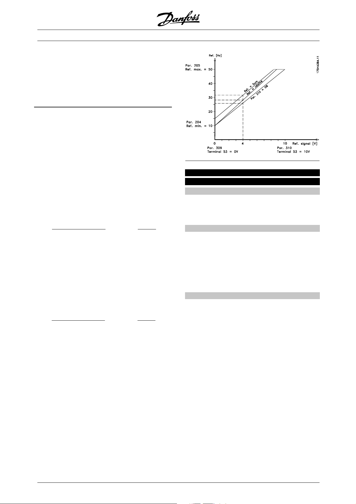
■Reference type
The example shows how the resulting reference is
calculated when Preset references are used together
with Sum and Relative in parameter 210 Reference
type. See Calculation of resulting reference.See
also the drawing in Reference handling.
The following parameters have been set:
Par. 204 Minimum reference: 10 Hz
Par. 205 Maximum reference: 50 Hz
Par. 211 Preset reference: 15%
Par. 308 Terminal 53, analog input: Reference [1]
Par. 309 Terminal 53, min. scaling: 0V
Par. 310 Terminal 53, max. scaling: 10 V
When parameter 210 Reference type is set to Sum
[0], one of the adjusted Preset references (par. 211-
214) will be added to the external referenc
es as a
percentage of the reference range. If terminal 53
is energized by an analog input voltage of 4 V, the
resulting reference will be as f
Par. 210 Reference type =Sum[0]
Par. 204 Minimum reference = 10.0 Hz
Reference contribution at 4 V = 16.0 Hz
P
ar. 211Preset reference = 6.0 Hz
Resulting reference = 32.0 Hz
ollows:
If parameter 210 Reference type is set to Relative
[1], one of the adjusted Preset references (par.
211-214) will be totaled as a percentage of the sum
of the present external references. If terminal 53
is energized by an analog input voltage of 4 V, the
resulting reference will be as follows:
Par. 210 Reference type = Relative [1]
Par. 204 Minimum reference = 10.0 Hz
Reference contribution at 4 V = 16.0 Hz
P
ar. 211Preset reference = 2.4 Hz
Resulting reference = 28.4 Hz
The graph in the next column shows the
resulting reference in relation to the external
reference varied from 0-10 V.
Parameter 210 Reference type has been programmed
for Sum [0] and Relative [1], respectively. In addition,
a graph is shown in which parameter 211 Preset
reference 1 is programmed for 0%.
VLT®6000 HVAC Series
210 Reference type
(REF. FUNCTION)
Value:
✭Sum (SUM)
Relative (RELATIVE)
External/preset (EXTERNAL/PRESET)
Function:
It is possible to define how the preset references
are to be added to the other references. For
this purpose, Sum or Relative is used. It is also
possible - by using the External/preset function - to
select whether a shift between external references
and preset references is wanted.
See Reference handling.
Description of choice:
If Sum [0] is selected, one of the adjusted preset
references (parameters 211-214 Preset reference)is
added to the other external references as a percentage
of the reference range (Ref
MIN
-Ref
If Relative [1] is selected, one of the adjusted
preset references (parameters 211-214 Preset
reference ) is totaled as a percentage of the sum
of the present external references.
If External/preset [2] is selected, it is possible to shift
between external references and preset references via
terminal 16, 17, 29, 32 or 33 (parameter 300, 301,
305, 306 or 307 Digital inputs). Preset references will
beapercentagevalueofthereferencerange.
External reference is the sum of the analog
references, pulse references and any references
from serial communication.
MAX
).
[0]
[1]
[2]
= factory setting. () = display text [] = value for use in communication via serial communication port
✭
96
MG.61.A5.02 - VLT is a registered Danfoss trademark
Page 97
VLT®6000 HVAC Series
NB!:
If Sum or Relative is selected, one of the
preset references will always be active. If the
preset references are to be without influence,
they should be set to 0% (as in the factory setting)
via the serial communication port.
211 Preset reference 1
(PRESET REF. 1)
212 Preset reference 2
(PRESET REF. 2)
213 Preset reference 3
(PRESET REF. 3)
214 Preset reference 4
(PRESET REF. 4)
Value:
-100.00 % - +100.00 %
✭ 0.00%
of the reference range/external reference
Function:
Four different preset references can be programmed
in parameters 211-214 Preset reference. The preset
reference is stated as a percentage value of the
reference range (Ref
MIN
-Ref
) or as a percentage
MAX
of the other external references, depending on the
choice made in parameter 210 Reference type.
The choice between the preset references can
be made by activating terminal 16, 17, 29, 32
or 33, cf. the table below.
Terminal 17/29/33 Terminal 16/29/32
preset ref. msb preset ref. lsb
0 0 Preset ref. 1
0 1 Preset ref. 2
1 0 Preset ref. 3
1 1 Preset ref. 4
Description of choice:
Set the required preset reference(s) that is/are
to be the options.
1.0-1.1 x I
(the rated output current of the frequency
VLT,N
converter), the frequency converter can only handle a
load intermittently, i.e. for short periods at a time. After
the load has been higher than I
that for a period the load is lower than I
note that if the current limit is set to less than I
,itmustbeensured
VLT,N
. Please
VLT,N
VLT,N
,the
acceleration torque will be reduced accordingly.
If the drive is in current limit and a stop command
is initiated with the stop button on the LCP key
pad, the drive output is immediately turned off
and the motor will coast to a stop.
NB!:
Current limit should not be used for
motor protection; parameter 117 is for
motor protection.
Description of choice:
Set the required maximum output current I
LIM
.
216 Frequency bypass, bandwidth
(FREQUENCY BYPASS B.W.)
Value:
0 (OFF) - 100 Hz
✭ Disable
Function:
Some systems call for some output frequencies to be
avoided because of mechanical resonance problems.
The frequencies to avoid can be programmed in
parameters 217-220 Frequency bypass .
In this parameter (216 Frequency bypass, bandwidth),
a definition can be given of a bandwidth around
each of these frequencies.
Description of choice:
The bypass bandwidth is equal to the programmed
bandwidth frequency. This bandwidth will be centered
around each bypass frequency.
Programming
215 Current limit, I
LIM
(CURRENT LIMIT)
Value:
0.1 - 1.1 x I
VLT,N
✭ 1.1 x I
VLT,N
[A]
Function:
This is where the maximum output current I
LIM
is set.
The factory setting corresponds to the rated output
current. Current limit is for protection of the frequency
converter. If the current limit is set within the range of
✭ = factory setting. () = display text [] = value for use in communication via serial communication port
MG.61.A5.02 - VLT is a registered Danfoss trademark
97
Page 98
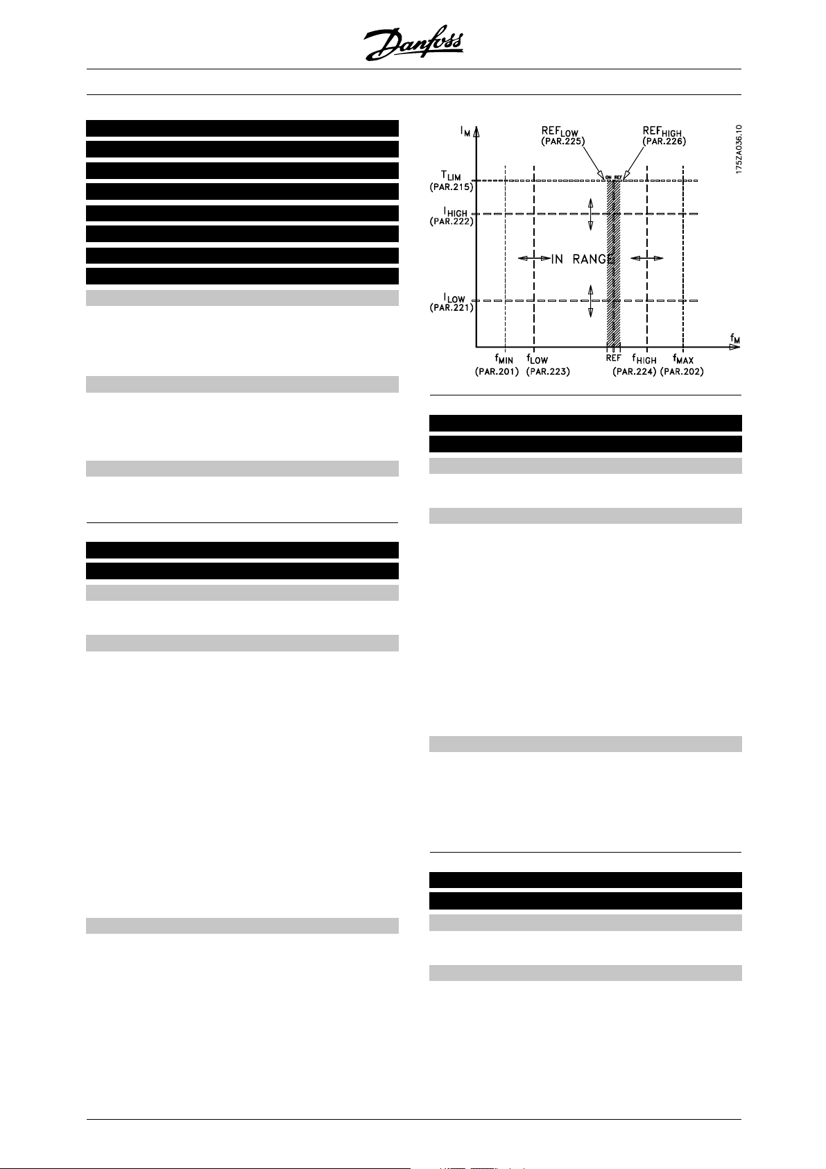
217 Frequency bypass 1
(BYPASS FREQ. 1)
218 Frequency bypass 2
(BYPASS FREQ. 2)
219 Frequency bypass 3
(BYPASS FREQ. 3)
220 Frequency bypass 4
(BYPASS FREQ. 4)
Value:
0 - 120/1000 HZ
✭ 120.0 Hz
The frequency range depends on the selection made
in parameter 200 Output frequency range.
Function:
Some systems call for some output frequencies
to be avoided because of mechanical resonance
problems in the system.
Description of choice:
Enter the frequencies to be avoided.
VLT®6000 HVAC Series
222 Warning: High current, I
(WARN. HIGH CURR.)
Value:
Parameter 221 - I
VLT,MAX
HIGH
✭ I
VLT,MAX
221 Warning: Low current, I
LOW
(WARN. LOW CURR.)
Value:
0.0 - par. 222 Warning: High current I
HIGH
,
✭ 0.0A
Function:
When the motor current is below the limit, I
LOW
,
programmed in this parameter, the display shows a
flashing CURRENT LOW, provided Warning [1] has
been selected in parameter 409 Function in case of no
load. The frequency converter will trip if parameter 409
Function in case of no load has been selected as Tri p [0].
The warning functions in parameters 221-228 are
not active during ramp-up after a start command,
ramp-down after a stop command or while
stopped. The warning functions are activated when
the output frequency has reached the resulting
reference. The signal outputs can be programmed
to generate a warning signal via terminal 42 or
45 and via the relay outputs.
Description of choice:
The lower signal limit I
must be programmed within
LOW
the normal working range of the frequency converter.
Function:
Ifthemotorcurrentisabovethelimit,I
HIGH
,
programmed in this parameter, the display shows
a flashing CURRENT HIGH.
The warning functions in parameters 221-228 are
not active during ramp-up after a start command,
ramp-down after a stop command or while stopped.
The warning functions are activated when the output
frequency has reached the resulting reference.
The signal outputs can be programmed to
generate a warning signal via terminal 42 or
45 and via the relay outputs.
Description of choice:
The upper signal limit of the motor frequency, f
HIGH
must be programmed within the normal working
range of the frequency converter. See drawing at
LOW
LOW
.
parameter 221 Warning: Low current, I
223 Warning: Low frequency, f
(WARN. LOW FR EQ.)
Value:
0.0 - parameter 224
✭ 0.0 Hz
Function:
If the output frequency is below the limit, f
LOW
,
programmed in this parameter, the display will
show a flashing FREQUENCY LOW.
The warning functions in parameters 221-228 are
not active during ramp-up after a start command,
ramp-down after a stop command or while stopped.
,
= factory setting. () = display text [] = value for use in communication via serial communication port
✭
98
MG.61.A5.02 - VLT is a registered Danfoss trademark
Page 99
VLT®6000 HVAC Series
The warning functions are activated when the output
frequency has reached the selected reference.
The signal outputs can be programmed to
generate a warning signal via terminal 42 or
45 and via the relay outputs.
Description of choice:
The lower signal limit of the motor frequency, f
LOW
,
must be programmed within the normal working
range of the frequency converter. See drawing at
parameter 221Warning: Low current, I
LOW
.
stopped. The warning functions are activated when
the output frequency has reached the selected
reference. The signal outputs can be programmed
to generate a warning signal via terminal 42 or
45 and via the relay outputs.
The reference limits in parameter 226 Warning:
High reference, Ref
, and in parameter 225
HIGH
Warning: Low reference, Ref
when remote reference has been selected.
In Open loop mode the unit for the reference is Hz,
while in Closed loop mode the unit is programmed
in parameter 415 Process units.
224 Warning: High frequency , f
(WARN. H IGH FREQ.)
Value:
Par. 200 Output frequency range = 0-120 Hz [0].
parameter 223 - 120 Hz
Par. 200 Output frequency range = 0-1000 Hz [1].
parameter 223 - 1000 Hz
HIGH
✭ 120.0 Hz
✭ 120.0 Hz
Description of choice:
The lower signal limit, Ref
be programmed within the normal working range of
the frequency converter, provided parameter 100
Configuration has been programmed for Open loop
[0]. In Closed loop [1] (parameter 100), Ref
must be within the reference range programmed
in parameters 204 and 205.
Function:
If the output frequency is above the limit, f
programmed in this parameter, the display will
show a flashing FREQUENCY HIGH.
The warning functions in parameters 221-228 are
not active during ramp-up after a start command,
ramp-down after a stop command or while stopped.
The warning functions are activated when the output
frequency has reached the resulting reference.
The signal outputs can be programmed to
generate a warning signal via terminal 42 or
45 and via the relay outputs.
HIGH
,
226 Warning: High reference , REF
(WARN. H IGH REF.)
Value:
REF
(par. 225) - 999,999.999
Low
Function:
If the resulting reference is above the limit, Ref
programmed in this parameter, the display shows
a flashing REFERENCE HIGH.
The warning functions in parameters 221-228 are
Description of choice:
The higher signal limit of the motor frequency, f
HIGH
must be programmed within the normal working
range of the frequency converter. See drawing at
pa-rameter 221 Warning: Low current, I
LOW
.
,
not active during ramp-up after a start command,
ramp-down after a stop command or while stopped.
The warning functions are activated when the output
frequency has reached the resulting reference.
The signal outputs can be programmed to
generate a warning signal via terminal 42 or
45 and via the relay outputs.
225 Warning: Low reference, REF
(WARN. LOW REF.)
Value:
-999,999.999 - REF
HIGH
(par.226)
LOW
✭ -999,999.999
The reference limits in parameter 226 Warning:
High reference, Ref
, and in parameter 227
HIGH
Warning: Low reference, Ref
when remote reference has been selected.
In Open loop the unit for the reference is Hz,
while in Closed loop the unit is programmed in
Function:
parameter 415 Process units .
When the remote reference lies under the limit,
Ref
, programmed in this parameter, the display
LOW
shows a flashing REFERENCE LOW.
The warning functions in parameters 221-228 are
not active during ramp-up after a start command,
ramp-down after a stop command or while
= factory setting. () = display text [] = value for use in communication via serial communication port
✭
Description of choice:
The upper signal limit, Ref
be programmed within the normal working range of
the frequency converter, provided parameter 100
Configuration has been programmed for Open loop
, are only active
LOW
, of the reference must
LOW
HIGH
✭ 999,999.999
, are only active
LOW
, of the reference must
HIGH
LOW
HIGH
,
Programming
MG.61.A5.02 - VLT is a registered Danfoss trademark
99
Page 100

VLT®6000 HVAC Series
[0]. In Closed loop [1] (parameter 100), Ref
HIGH
must be within the reference range programmed
in parameters 204 and 205.
227 Warning: Low feedback, FB
LOW
(WARN LOW FDBK)
Value:
-999,999.999 - FB
(parameter 228)
HIGH
✭ -999.999,999
Function:
If the feedback signal is below the limit, FB
LOW
,
programmed in this parameter, the display will
show a flashing FEEDBACK LOW.
The warning functions in parameters 221-228 are
not active during ramp-up after a start command,
ramp-down after a stop command or while
stopped. The warning functions are activated when
the output frequency has reached the selected
reference. The signal outputs can be programmed
to generate a warning signal via terminal 42 or
45 and via the relay outputs.
In Closed loop, the unit for the feedback is programmed
in parameter 415 Process units.
Description of choice:
Set the required value within the feedback range
(parameter 413 Minimum feedback, FB
414 Maximum feedback, FB
MAX
).
MIN
,and
Description of choice:
Set the required value within the feedback range
(parameter 413 Minimum feedback, FB
414 Maximum feedback, FB
MAX
).
228 Warning: High feedback, FB
MIN
HIGH
,and
(WARN. HIGH FDBK)
Value:
FB
LOW
(parameter 227) - 999,999.999
✭ 999.999,999
Function:
If the feedback signal is above the limit, FB
HIGH
,
programmed in this parameter, the display will
show a flashing FEEDBACK HIGH.
The warning functions in parameters 221-228 are
not active during ramp-up after a start command,
ramp-down after a stop command or while stopped.
The warning functions are activated when the output
frequency has reached the selected reference.
The signal outputs can be programmed to
generate a warning signal via terminal 42 or
45 and via the relay outputs.
In Closed loop, the unit for the feedback is programmed
in parameter 415 Process units.
✭ = factory setting. () = display text [] = value for use in communication via serial communication port
100
MG.61.A5.02 - VLT is a registered Danfoss trademark
 Loading...