

Design Guide
VLT® 6000 HVAC
Contents
VLT
®
6000 HVAC Series
Introduction to HVAC
Software version 4
Safety regulations 5
Warning against unintended start 5
Introduction to the Design Guide 7
Available literature 8
Fire mode 11
Star/delta starter or soft-starter not required 15
Control principle 17
CE labelling 18
The new standard 19
The new standard 20
The new standard 21
Choice of frequency converter 25
Unpacking and ordering a VLT frequency converter 28
Type code ordering number string 28
Ordering form 32
PC software and serial communication 33
PC Software tools 33
Fieldbus options 33
Profibus 34
LON - Local Operating Network 34
DeviceNet 34
Modbus RTU 34
4
Installation
Mains supply (L1, L2, L3) 41
Max. imbalance of supply voltage 41
Technical data, mains supply 3 x 200-240V 46
Technical data, mains supply 3 x 380-460V 47
Technical data, mains supply 3 x 525-600 V 52
Fuses 57
Mechanical dimensions 60
Mechanical installation 64
General information about electrical installation 67
High voltage warning 67
Earthing 67
Cables 67
Screened/armoured cables 68
Extra protection with regard to indirect contact 68
RFI switch 69
High voltage test 72
Heat emission from VLT 6000 HVAC 72
Ventilation of integrated VLT 6000 HVAC 72
EMC correct electrical installation 72
Use of EMC-correct cables 74
Electrical installation - earthing of control cables 75
41
MG.61.B6.02 - VLT
®
is a registered Danfoss trademark 1

®
VLT
Electrical installation, enclosures 76
Tightening-up torque and screw sizes 83
Mains connection 83
Motor connection 83
Direction of motor rotation 84
Motor cables 84
Motor thermal protection 85
Earth connection 85
Installation of 24 Volt external DC supply 85
DC bus connection 85
High-voltage relay 85
Control card 85
Electrical installation, control cables 86
Switches 1-4 87
Bus connection 87
Connection examples, VLT 6000 HVAC 88
6000 HVAC Series
Programming
Control unit LCP 90
Control keysfor parameter setup 90
Indicator lamps 91
Local control 91
Display mode 92
Navigation between display modes 94
Changing data 95
Manual initialisation 95
Quick Menu 96
Operation and Display 001-017 98
The Setup configuration 98
Setup of user-defined readout 99
Load and Motor 100-117 105
Configuration 105
Motor power factor (Cos ø) 111
Reference handling 113
Reference type 116
Inputs and outputs 300-365 121
Analogue inputs 125
Analog/digital outputs 128
Relay outputs 132
Application functions 400-427 135
Sleep mode 136
PID for process control 141
PID overview 143
Feedback handling 143
Serial communication for FC protocol 150
Protocols 150
Telegram communication 150
Telegram build-up under FC protocol 151
Data character (byte) 152
90
2 MG.61.B6.02 - VLT
®
is a registered Danfoss trademark

®
VLT
Process word 156
Control word according to FC protocol 157
Status word as per FC protocol 158
Serial communication reference 159
Present output frequency 160
Serial communication 500 - 556 161
Extended status word, warning word, and alarm word 168
Service functions 600-631 171
Electrical installation of the relay card 176
Description of Real Time Clock 177
6000 HVAC Series
All about VLT 6000 HVAC
Status messages 180
List of warnings and alarms 182
Aggressive environments 189
Calculation of resulting reference 189
Galvanic isolation (PELV) 190
Earth leakage current 190
Extreme running conditions 191
Peak voltage on motor 192
Switching on the input 192
Acoustic noise 193
Derating for ambient temperature 193
Derating for air pressure 194
Derating for running at low speed 194
Derating for long motor cables or cables with larger cross-section 194
Derating for high switching frequency 194
Vibration and shock 195
Air humidity 195
Efficiency 196
Mains supply interference/harmonics 197
Power factor 197
(Emission) 197
EMC Immunity 199
Definitions 201
Parameter overview and factory settings 203
180
MG.61.B6.02 - VLT
Index
®
is a registered Danfoss trademark 3
210

®
VLT
6000 HVAC Series
Software version
VLT 6000 HVAC
Design Guide
Software version: 3.2x
This Design Guide can be used with all VLT 6000 HVAC frequency converters with software version 3.2x.
The software version number can be seen from parameter 624.
4 MG.61.B6.02 - VLT
®
is a registered Danfoss trademark
The voltage of the frequency converter is
dangerous whenever the equipment is
connected to mains. Incorrect installation
of the motor or the frequency converter
may cause damage to the equipment, serious personal injury or death.
Consequently, the instructions in this
manual, as well as national and local rules
and safety regulations, must be complied
with.
The Protective Extra Low Voltage (PELV)
requirements stated in IEC 61800-5-1 are
not fulfilled at altitudes above 2000 m
(6562 ft.). For 200V frequency converters
the requirements are not fulfilled at altitudes above 5000 m (16 404 ft.). Please
contact Danfoss Drives for further information.
Safety regulations
1. The frequency converter must be disconnected from mains if repair work is to be carried
out. Check that the mains supply has been
disconnected and that the necessary time
has passed before removing motor and
mains plugs.
2. The [OFF/STOP] key on the control panel of
the frequency converter does
the equipment from mains and is thus
be used as a safety switch.
3. Correct protective earthing of the equipment
must be established, the user must be protected against supply voltage, and the motor
must be protected against overload in accordance with applicable national and local
regulations.
4. The earth leakage currents are higher than
3.5 mA.
not disconnect
not to
®
VLT
Warning against unintended start
6000 HVAC Series
Note: The function is initialised at 1.0 x rated
motor current and rated motor frequency
(see parameter 117, Motor thermal protec-
tion).
6. Do
7. Reliable galvanic isolation (PELV) is not
8. Please note that the frequency converter has
1. The motor can be brought to a stop by means
2. While parameters are being changed, the
3. A motor that has been stopped may start if
not remove the plugs for the motor and
mains supply while the frequency converter
is connected to mains. Check that the mains
supply has been disconnected and that the
necessary time has passed before removing
motor and mains plugs.
complied with if the RFI switch is placed in
OFF position. This means that all control in and outputs can only be considered low-voltage terminals with basic galvanic isolation.
more voltage inputs than L1, L2 and L3, when
the DC-bus terminals are used.
Check that
connected and that the necessary time has
passed before repair work is commenced.
of digital commands, bus commands, references or a local stop, while the frequency
converter is connected to mains.
If personal safety considerations make it necessary to ensure that no unintended start
occurs,
cient.
motor may start. Consequently,
[OFF/STOP] must always be activated, following which data can be modified.
faults occur in the electronics of the frequency converter, or if a temporary overload or a
fault in the supply mains or the motor connection ceases.
all voltage inputs have been dis-
these stop functions are not suffi-
the stop key
Introduction to HVAC
5. Protection against motor overload is included
in the factory setting. Parameter 117, Motor
thermal protection default value is ETR trip 1.
MG.61.B6.02 - VLT
®
is a registered Danfoss trademark 5
®
VLT
6000 HVAC Series
Warning:
Touching the electrical parts may be fatal - even after the equipment has been disconnected from mains.
VLT 6002 - 6005, 200-240 V: wait at least 4 minutes
VLT 6006 - 6062, 200-240 V : wait at least 15 minutes
VLT 6002 - 6005, 380-460 V: wait at least 4 minutes
VLT 6006 - 6072, 380-460 V: wait at least 15 minutes
VLT 6102 - 6352, 380-460 V: wait at least 20 minutes
VLT 6402 - 6602, 380-460 V: wait at least 40 minutes
VLT 6002 - 6006, 525-600 V: wait at least 4 minutes
VLT 6008 - 6027, 525-600 V: wait at least 15 minutes
VLT 6032 - 6072, 525-600 V: wait at least 30 minutes
VLT 6102 - 6402, 525-600 V: wait at least 20 minutes
VLT 6502 - 6652, 525-600 V: wait at least 30 minutes
6 MG.61.B6.02 - VLT
®
is a registered Danfoss trademark

®
VLT
Introduction to the Design Guide
This Design Guide is a tool intended to facilitate the sizing of systems in which VLT 6000 HVAC frequency
converters are used.
HVAC stands for Heating Ventilation Air-Conditioning.
This Design Guide progresses step-by-step through the different procedures required for selecting, installing and
programming a VLT 6000 HVAC.
The Design Guide forms part of the literature concept supplied with VLT 6000 HVAC. However, the Design Guide
is the most comprehensive document available.
When a VLT 6000 HVAC is supplied, it is accompanied by Operating Instructions and a Quick Setup Guide. See
the section Other Literature.
Operating Instructions:
Quick Setup Guide:
Design Guide:
This Design Guide is split in four sections that have information about VLT 6000 HVAC.
Introduction to HVAC:
There are also examples of applications and information is given about Danfoss
The specification section deals with the requirements relating to being allowed to
The section ends with an Ordering Guide that makes it easier for you to specify
Describe how to ensure optimum mechanical and electrical installation, and also
deal with commissioning and service. The Operating Instructions furthermore provide a description of the software parameters, thereby ensuring that you can easily
fit the VLT 6000 HVAC into your application.
Helps you get your VLT 6000 HVAC installed and commissioned quickly.
Used when designing systems with VLT 6000 HVAC. The Design Guide gives all
useful information about the VLT 6000 HVAC and HVAC systems. There is a selection tool for you to choose the right VLT 6000 HVAC with the relevant options
and modules. The Design Guide has examples of the most common types of HVAC
applications. In addition, the Design Guide has all information relating to Serial
Communication.
This section tells you the advantages that can be obtained by using frequency
converters in HVAC systems. Furthermore, you can read about the way a frequency converter operates and about the advantages of the VLT 6000 HVAC, such
as AEO - Automatic Energy Optimisation, RFI filter and other HVAC-relevant functions.
and CE-labelling.
supply and install frequency converters. This section can be used in contract
documents, whereby the total list of requirements relating to frequency converters
is determined.
and order a VLT 6000 HVAC.
6000 HVAC Series
Introduction to HVAC
MG.61.B6.02 - VLT
®
is a registered Danfoss trademark 7

Introduction to the Design Guide
VLT
®
6000 HVAC Series
Installation:
This section shows you how to carry out correct mechanical installation of a VLT
6000 HVAC.
In addition, the section has a description of how you ensure that the installation
of the VLT 6000 HVAC is EMC-correct. Furthermore, the section includes a list
of mains and motor connections, as well as a description of control card terminals.
Programming:
This section describes the control unit and the software parameters for the VLT
6000 HVAC. There is also a guide to the Quick Setup menu, which means that
you will be able to start using your application very quickly.
All about VLT 6000:
This section has information about status, warning and fault indications from
the VLT 6000 HVAC. In addition, the section has technical data, service information, factory settings and information on special conditions.
NB!
This symbol indicates something to be noted by the reader.
This symbol indicates a general warning.
This symbol indicates a high-voltage warning.
Available literature
Below is a list of the literature available for VLT 6000 HVAC. It must be noted that there may be deviations from
one country to the next.
Please also refer to our web site http://drives.danfoss.com for information about new literature.
Supplied with the unit:
Operating instructions MG.61.AX.YY
Quick Setup MG.60.CX.YY
High Power Introduction Guide MI.90.JX.YY
Communication with VLT 6000 HVAC:
Profibus Manual MG.90.DX.YY
Metasys N2 Manual MG.60.FX.YY
LonWorks Manual MG.60.EX.YY
Landis/Staefa Apogee FLN Manual MG.60.GX.YY
Modbus RTU Manual MG.10.SX.YY
DeviceNet Manual MG.50.HX.YY
Instructions for VLT 6000 HVAC:
LCP Remote Kit IP20 MI.56.AX.51
LCP Remote Kit IP54 MI.56.GX.52
Sine wave-filter MI.56.DX.51
IP20 terminal cover MI.56.CX.51
8 MG.61.B6.02 - VLT
®
is a registered Danfoss trademark
®
VLT
Various literature for VLT 6000 HVAC:
Operating Instructions MG.60.AX.YY
Design Guide MG.61.BX.YY
Data sheet MD.60.AX.YY
VLT 6000 HVAC Cascade Controller MG.60.IX.YY
X = version number YY = language version
Why use a frequency converter for controlling
fans and pumps?
A frequency converter takes advantage of the fact that centrifugal fans and pumps follow the laws of proportionality
for such fans and pumps. For further information see the text The Laws of Proportionality.
The clear advantage - energy savings
The very clear advantage of using a frequency converter for controlling the speed of fans or pumps lies in the
electricity savings.
When comparing with alternative control systems and technologies, a frequency converter is the optimum energy
control system for controlling fan and pump systems.
6000 HVAC Series
Introduction to HVAC
The graph is showing fan curves (A, B and C) for
reduced fan volumes.
MG.61.B6.02 - VLT
®
is a registered Danfoss trademark 9
When using a frequency converter to reduce fan
capacity to 60% - more than 50% energy savings
may be obtained in typical applications.
®
VLT
Example of energy savings
As can be seen from the figure (the laws of proportionality), the flow is controlled by changing the rpm. By reducing
the speed only 20% from the rated speed, the flow is also reduced by 20%. This is because the flow is directly
proportional to the rpm. The consumption of electricity, however, is reduced by 50%.
If the system in question only needs to be able to supply a flow that corresponds to 100% a few days in a year,
while the average is below 80% of the rated flow for the remainder of the year, the amount of energy saved is even
more than 50%.
The laws of proportionality
The figure below describes the dependence of flow, pressure and power consumption on rpm.
Q = Flow P = Power
= Rated flow P1 = Rated power
Q
1
= Reduced flow P2 = Reduced power
Q
2
H = Pressure n = Speed regulation
= Rated pressure n1 = Rated speed
H
1
= Reduced pressure n2 = Reduced speed
H
2
6000 HVAC Series
The example below is calculated on the basis of pump
characteristics obtained from a pump datasheet.
The result obtained shows energy savings in excess
of 50% at the given flow distribution over a year. The
pay back period depends on the price per kwh and
price of frequency converter. In this example it is less
than a year when compared with valves and constant
speed.
Q
Flow
Pressure
Power
Example with varying flow over 1 year
Energy savings
P
shaft=Pshaft output
Flow distribution over 1 year
1
:
Q
2
:
P
:
P
n
1
=
n
2
H
1
=
H
2
1
=
(
2
2
n
1
(
)
n
2
3
n
1
)
n
2
10 MG.61.B6.02 - VLT
®
is a registered Danfoss trademark
VLT
®
6000 HVAC Series
Introduction to HVAC
m3/h
350 5 438 42,5 18.615 42,5 18.615
300 15 1314 38,5 50.589 29,0 38.106
250 20 1752 35,0 61.320 18,5 32.412
200 20 1752 31,5 55.188 11,5 20.148
150 20 1752 28,0 49.056 6,5 11.388
100 20 1752 23,0 40.296 3,5 6.132
Distribution Valve regulation Frequency converter control
% Hours Power Consumption Power Consumption
A1 - B
Σ 100 8760 275.064 26.801
1
kWh A1 - C
1
Fire mode
over pressure and result in damage to
NB!
Please note the frequency converter is
only one component of the HVAC system.
Correct function of Fire Mode depends on
the correct design and selection of system
components. Ventilation systems working
in life safety applications have to be approved by the local fire Authorities. Non-
interruption of the frequency converter
due to Fire Mode operation may cause
HVAC system and components, including dampers and air ducts. The frequency converter itself may be damaged and it may cause damage or fire.
Danfoss A/S accepts no responsibility
for errors, malfunctions personal injury or any damage to the frequency
converter itself or components herein,
HVAC systems and components herein or other property when the frequen-
kWh
MG.61.B6.02 - VLT
®
is a registered Danfoss trademark 11

cy converter has been programmed for
Fire Mode. In no event shall Danfoss be
liable to the end user or any other party
for any direct or indirect, special or
consequential damage or loss suffered
by such party, which has occurred due
to the frequency converter being programmed and operated in Fire Mode
The Fire Mode function is made to ensure the VLT
6000 can run without interruption. This means most
alarms and warnings will not cause a trip and trip lock
is disabled. This is useful in case of fire or other emergencies. Until the motor wires or the frequency converter itself are destroyed every attempt is made to
keep running. A warning will flash when these limits
have been exceeded. If the warning still flashes after
a power cycle please contact your local Danfoss supplier. In the following is a table to show the alarms and
when the frequency converter changes state depend-
®
VLT
6000 HVAC Series
ing on selection in parameter 430. Trip and lock ([0] in
parameter 430) are valid in normal operation mode.
Fire Mode trip and reset ([1] or [2] in parameter 430)
means that a reset is automatically performed without
the need of manual resetting. Go to Fire Mode bypass
([3] in parameter 430) is valid in case one of the mentioned alarms causes a trip. After the in parameter 432
selected time delay has passed an output is set. This
output is programmed in parameter 319, 321, 323 or
326. If a relay option is fitted it can also be selected in
parameter 700, 703, 706 or 709. In parameter 300 and
301 it can be selected if the logic, for the Fire Mode
activation, shall be active high or low. Please note parameter 430 must be different to [0] for the Fire Mode
to be enabled.
To be able to use Fire Mode please also note that input
27 must be “high” and no coast bit present via fieldbus.
To ensure that no coast can interrupt Fire Mode via
fieldbus please select Digital Input [0] in par. 503. Then
coasting via fieldbus disabled.
12 MG.61.B6.02 - VLT
®
is a registered Danfoss trademark

VLT
®
6000 HVAC Series
No. Description TRIP
[0]
2 Live zero fault
(LIVE ZERO ERROR)
4 Mains imbalance
(MAINS IMBALANCE)
7 Overvoltage
(DC LINK OVERVOLT)
8 Undervoltage
(DC LINK UNDERVOLT)
9 Inverter overloaded
(INVERTER TIME)
10 Motor overloaded
(MOTOR TIME)
11 Motor thermistor(MOTOR
THERMISTOR)
12 Current limit
(CURRENT LIMIT)
13 Overcurrent
(OVERCURRENT)
14 Earth fault
(EARTH FAULT)
15 Switch mode fault
(SWITCH MODE FAULT)
16 Short-circuit
(CURR.SHORT CIRCUIT)
17 Serial communication timeout
(STD BUSTIMEOUT)
18 HPFB bus timeout
(HPFB TIMEOUT)
22 Auto-optimation fault
(AMA FAULT)
29 Heat-sink temperature too high
(HEAT SINK OVERTEMP.)
30 Motor phase U missing
(MISSING MOT.PHASE U)
31 Motor phase V missing
(MISSING MOT.PHASE V)
32 Motor phase W missing
(MISSING MOT.PHASE W)
34 HPFB communication fault
(HPFB TIMEOUT)
37 Inverter fault (GATE DRIVE
FAULT)
60 Safety stop
(EXTERNAL FAULT)
63 Output current low
(I MOTOR < I LOW)
80 Fire mode was active
(FIRE MODE WAS ACTIVE)
99 Unknown fault
(UNKNOWN FAULT)
X
x x x
x
x
x
x
x
x
x x x x
x x x x
x x x x
x x x x
x
x
x
x x x
x
x
x
x
x x x x
x
x
x
x x
LOCK
[0]
FIRE MODE
Trip & reset
[1], [2]
Go to
FIRE MODE
BYPASS [3]
Introduction to HVAC
MG.61.B6.02 - VLT
®
is a registered Danfoss trademark 13

®
VLT
6000 HVAC Series
Better control
If a frequency converter is used for controlling the flow or pressure of a system, improved control is obtained.
A frequency converter can vary the speed of the fan or pump, thereby obtaining variable control of flow and
pressure.
Furthermore, a frequency converter can quickly adapt the speed of the fan or pump to new flow or pressure
conditions in the system.
Simple control of process (Flow, Level or Pressure) utilizing the built in PID control.
14 MG.61.B6.02 - VLT
®
is a registered Danfoss trademark

VLT
®
6000 HVAC Series
Simpler installation when using a frequency converter
A frequency converter can replace a traditional control
system, in which mechanical dampers and valves are
used for controlling flow or pressure.
The great advantage involved in using a frequency
converter is that the system becomes simpler, since a
lot of the mechanical and electrical equipment is no
longer required.
V-belts no longer required
In mechanical control systems, where the fan is driven
by V-belts, it is necessary to change belt pulleys in order to adjust the fan speed to match the necessary
maximum load. Using a frequency converter, the Vbelts can be replaced by directly driven motors, whose
speed is changed simply by means of the frequency
converter.
The efficiency of the system improves and the entire
installation takes up less space. There is no dust from
the V-belt and less maintenance.
Regulating dampers and valves no longer required
Since the flow or pressure can be controlled by means
of the frequency converter, no regulating dampers and
valves are required in the system.
Cos φ compensation
Introduction to HVAC
Generally speaking, a frequency converter with a cos φ of 1 provides power factor correction for the cos φ of the
motor, which means that there is no need to make allowance for the cos φ of the motor when sizing the power
factor correction unit.
Star/delta starter or soft-starter not required
When larger motors are started, it is necessary in
many countries to use equipment that limits the startup current. In more traditional systems, a star/delta
starter or soft-starter is widely used. Such motor starters are not required if a frequency converter is used.
As illustrated in the figure below, a frequency converter
does not consume more than rated current.
1 = VLT 6000 HVAC
2 = Star/delta starter
3 = Soft-starter
4 = Start directly on mains
Using a frequency converter saves money
The example on the following page shows that a lot of equipment is not required when a frequency converter is
used. It is possible to calculate the cost of installing the two different systems. In the example on the following
MG.61.B6.02 - VLT
®
is a registered Danfoss trademark 15
®
VLT
6000 HVAC Series
page, the two systems can be established at roughly the same price.
Without a frequency converter
The figure shows a fan system made in the traditional way.
D.D.C. = Direct Digital Control E.M.S. = Energy Management system
V.A.V. = Variable Air Volume
Sensor P = Pressure Sensor T = Temperature
With a frequency converter
The figure shows a fan system controlled by VLT 6000 HVAC frequency converters.
16 MG.61.B6.02 - VLT
®
is a registered Danfoss trademark
VLT
®
6000 HVAC Series
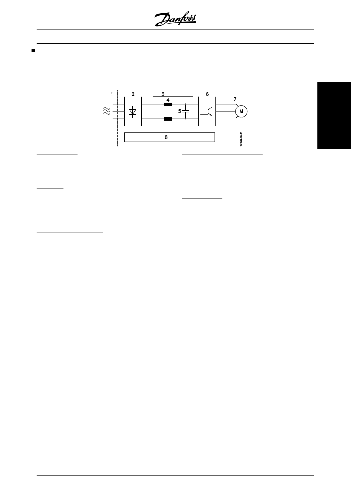
Control principle
A frequency converter rectifies AC voltage from mains
into DC voltage, after which this DC voltage is converted into a AC current with a variable amplitude and
frequency.
1. Mains voltage
3 x 200 - 240 V AC, 50 / 60 Hz.
3 x 380 - 460 V AC, 50 / 60 Hz.
3 x 525 - 600 V AC, 50 / 60 Hz.
2. Rectifier
A three-phase rectifier bridge that rectifies AC current
into DC current.
3. Intermediate circuit
DC voltage = 1.35 x mains voltage [V].
4. Intermediate circuit coils
Even out the intermediate circuit voltage and reduce
the harmonic current feedback to the mains supply.
The motor is thus supplied with variable voltage and
frequency, which enables infinitely variable speed
control of three-phased, standard AC motors.
Introduction to HVAC
5. Intermediate circuit capacitors
Even out the intermediate circuit voltage.
6. Inverter
Converts DC voltage into variable AC voltage with a
variable frequency.
7. Motor voltage
Variable AC voltage, 0-100% of mains supply voltage.
8. Control card
This is where to find the computer that controls the inverter which generates the pulse pattern by which the
DC voltage is converted into variable AC voltage with
a variable frequency.
MG.61.B6.02 - VLT
®
is a registered Danfoss trademark 17
VLT
®
6000 HVAC Series
CE labelling
What is CE labelling?
The purpose of CE labelling is to avoid technical obstacles to trade within EFTA and the EU. The EU has
introduced the CE label as a simple way of showing
whether a product complies with the relevant EU directives. The CE label says nothing about the specifications or quality of the product. Frequency converters
are regulated by three EU directives:
The machinery directive (98/37/EEC)
All machines with critical moving parts are covered by
the machinery directive, which came into force on 1
January 1995. Since a frequency converter is largely
electrical, it does not fall under the machinery directive.
However, if a frequency converter is supplied for use
in a machine, we provide information on safety aspects
relating to the frequency converter. We do this by
means of a manufacturer's declaration.
The low-voltage directive (73/23/EEC)
Frequency converters must be CE labelled in accordance with the low-voltage directive, which came into
force on 1 January 1997. The directive applies to all
electrical equipment and appliances used in the 50 1000 Volt AC and the 75 - 1500 Volt DC voltage
ranges. Danfoss CE labels in accordance with the directive and issues a declaration of conformity upon
request.
The EMC directive (89/336/EEC)
EMC is short for electromagnetic compatibility. The
presence of electromagnetic compatibility means that
the mutual interference between different components/appliances is so small that the functioning of the
appliances is not affected.
The EMC directive came into force on 1 January 1996.
Danfoss CE labels in accordance with the directive
and issues a declaration of conformity upon request.
In order that EMC-correct installation can be carried
out, this manual gives detailed instructions for installation. In addition, we specify the standards which our
different products comply with. We offer the filters that
can be seen from the specifications and provide other
types of assistance to ensure the optimum EMC result.
In the great majority of cases, the frequency converter
is used by professionals of the trade as a complex
component forming part of a larger appliance, system
or installation. It must be noted that the responsibility
for the final EMC properties of the appliance, system
or installation rests with the installer.
NOTE: VLT 6001-6072, 525-600 V are not CE labelled.
Application examples
The next few pages give typical examples of applications within HVAC.
If you would like to receive further information about a given application, please ask your Danfoss supplier for an
information sheet that gives a full description of the application.
Variable Air Volume
3 x 200/208/220/230/240 V ±10%
Ask for The Drive to...Improving Variable Air Volume Ventilation Systems MN.60.A1.02
Constant Air Volume
3 x 200/208/220/230/240 V ±10%
Ask for The Drive to...Improving Constant Air Volume Ventilation Systems MN.60.B1.02
Cooling Tower Fan
3 x 200/208/220/230/240 V ±10%
Ask for The Drive to...Improving fan control on cooling towers MN.60.C1.02
Condenser pumps
3 x 200/208/220/230/240 V ±10%
Ask for The Drive to...Improving condenser water pumping systems MN.60.F1.02
Primary pumps
3 x 200/208/220/230/240 V ±10%
Ask for The Drive to...Improve your primary pumping in primay/secondary pumping systems MN.60.D1.02
Secondary pumps
3 x 200/208/220/230/240 V ±10%
Ask for The Drive to...Improve your secondary pumping in primay/secondary pumping systems MN.60.E1.02
18 MG.61.B6.02 - VLT
®
is a registered Danfoss trademark
®
VLT
6000 HVAC Series
Variable Air Volume
VAV or Variable Air Volume systems, are used to control both the ventilation and temperature to satisfy the requirements of a building. Central VAV systems are considered to be the most energy efficient method to air
condition buildings. By designing central systems instead of distributed systems, a greater efficiency can be obtained.
The efficiency comes from utilizing larger fans and larger chillers which have much higher efficiencies than small
motors and distributed air-cooled chillers. Savings are also seen from the decreased maintenance requirements.
The new standard
While dampers and IGVs work to maintain a constant
pressure in the ductwork, a frequency converter solution saves much more energy and reduces the complexity of the installation. Instead of creating an
artificial pressure drop or causing a decrease in fan
efficiency, the frequency converter decreases the
speed of the fan to provide the flow and pressure required by the system.
Centrifugal devices such as fans behave according to
the centrifugal laws. This means the fans decrease the
Cooling coil
D1
D2
Heating coil
Filter
pressure and flow they produce as their speed is reduced. Their power consumption is thereby significantly reduced.
The return fan is frequently controlled to maintain a
fixed difference in airflow between the supply and return. The advanced PID controller of the VLT 6000
HVAC can be used to eliminate the need for additional
controllers.
Pressure
signal
VAV boxes
Supply fan
3
Pressure
transmitter
Flow
T
Introduction to HVAC
D3
Return fan
3
Flow
MG.61.B6.02 - VLT
®
is a registered Danfoss trademark 19
®
VLT
6000 HVAC Series
Constant Air Volume
CAV, or Constant Air Volume systems are central ventilation systems usually used to supply large common zones
with the minimum amounts of fresh tempered air. They preceded VAV systems and therefore are found in older
multi-zoned commercial buildings as well. These systems preheat amounts of fresh air utilizing Air Handling Units
(AHUs) with a heating coil, and many are also used to air condition buildings and have a cooling coil. Fan coil units
are frequently used to assist in the heating and cooling requirements in the individual zones.
The new standard
With a frequency converter, significant energy savings
can be obtained while maintaining decent control of
the building. Temperature sensors or CO2 sensors
can be used as feedback signals to frequency converters. Whether controlling temperature, air quality,
or both, a CAV system can be controlled to operate
based on actual building conditions. As the number of
people in the controlled area decreases, the need for
fresh air decreases. The CO2 sensor detects lower
levels and decreases the supply fans speed. The return fan modulates to maintain a static pressure setpoint or fixed difference between the supply and return
air flows.
With temperature control, especially used in air conditioning systems, as the outside temperature varies as
well as the number of people in the controlled zone
changes, different cooling requirements exist. As the
temperature decreases below the set-point, the supply
fan can decrease its speed. The return fan modulates
to maintain a static pressure set-point. By decreasing
the air flow, energy used to heat or cool the fresh air is
also reduced, adding further savings.
Several features of Danfoss HVAC dedicated frequency converter, the VLT 6000 HVAC can be utilized to
improve the performance of your CAV system. One
concern of controlling a ventilation system is poor air
quality. The programmable minimum frequency can
be set to maintain a minimum amount of supply air regardless of the feedback or reference signal. The frequency converter also includes a two zone, 2 setpoint
PID controller which allows monitoring both temperature and air quality. Even if the temperature requirement is satisfied, the drive will maintain enough supply
air to satisfy the air quality sensor. The controller is
capable of monitoring and comparing two feedback
signals to control the return fan by maintaining a fixed
differential air flow between the supply and return
ducts as well.
D1
D3
D2
Cooling coil
Heating coil
Temperature
signal
Filter
Supply fan
Temperature
transmitter
Pressure
signal
Return fan
Pressure
transmitter
20 MG.61.B6.02 - VLT
®
is a registered Danfoss trademark
®
VLT
6000 HVAC Series
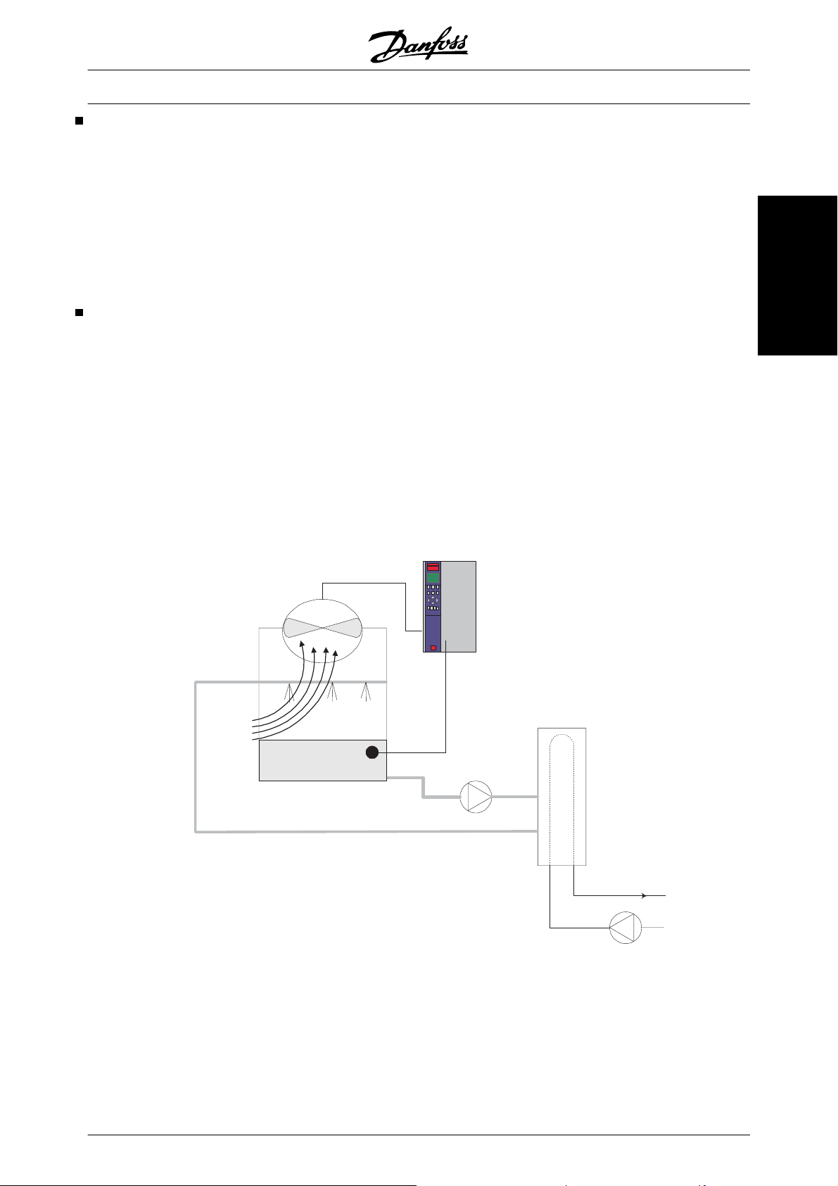
Cooling Tower Fan
Cooling Tower Fans are used to cool condenser water in water cooled chiller systems. Water cooled chillers
provide the most efficient means of creating chilled water. They are as much as 20% more efficient than air cooled
chillers. Depending on climate, cooling towers are often the most energy efficient method of cooling the condenser
water from chillers.
They cool the condenser water by evaporation.
The condenser water is sprayed into the cooling tower onto the cooling towers “fill” to increase its surface area.
The tower fan blows air through the fill and sprayed water to aid in the evaporation. Evaporation removes energy
from the water dropping its temperature. The cooled water collects in the cooling towers basin where it is pumped
back into the chillers condenser and the cycle is repeated.
The new standard
With a frequency converter, the cooling towers fans
can be controlled to the required speed to maintain the
condenser water temperature.T frequency converters
can also be used to turn the fan on and off as needed.
Several features of Danfoss HVAC dedicated drive,
the VLT 6000 HVAC can be utilized to improve the
performance of your cooling tower fans application. As
the cooling tower fans drop below a certain speed, the
effect the fan has on cooling the water becomes small.
Also, when utilizing a gear-box to frequency converter
the tower fan, a minimum speed of 40-50% may be
required.
Water Inlet
The customer programmable minimum frequency setting of the is available to maintain this minimum frequency even as the feedback or speed reference calls
for lower speeds.
Also as a standard feature, you can program the frequency converter to enter a “sleep” mode and stop the
fan until a higher speed is required. Additionally, some
cooling tower fans have undesireable frequencies that
may cause vibrations. These frequencies can easily
be avoided by programming the bypass frequency
ranges in the frequency converter.
Introduction to HVAC
BASIN
Water Outlet
Temperature
Sensor
Conderser
Water pump
CHILLER
Supply
MG.61.B6.02 - VLT
®
is a registered Danfoss trademark 21
®
VLT
6000 HVAC Series
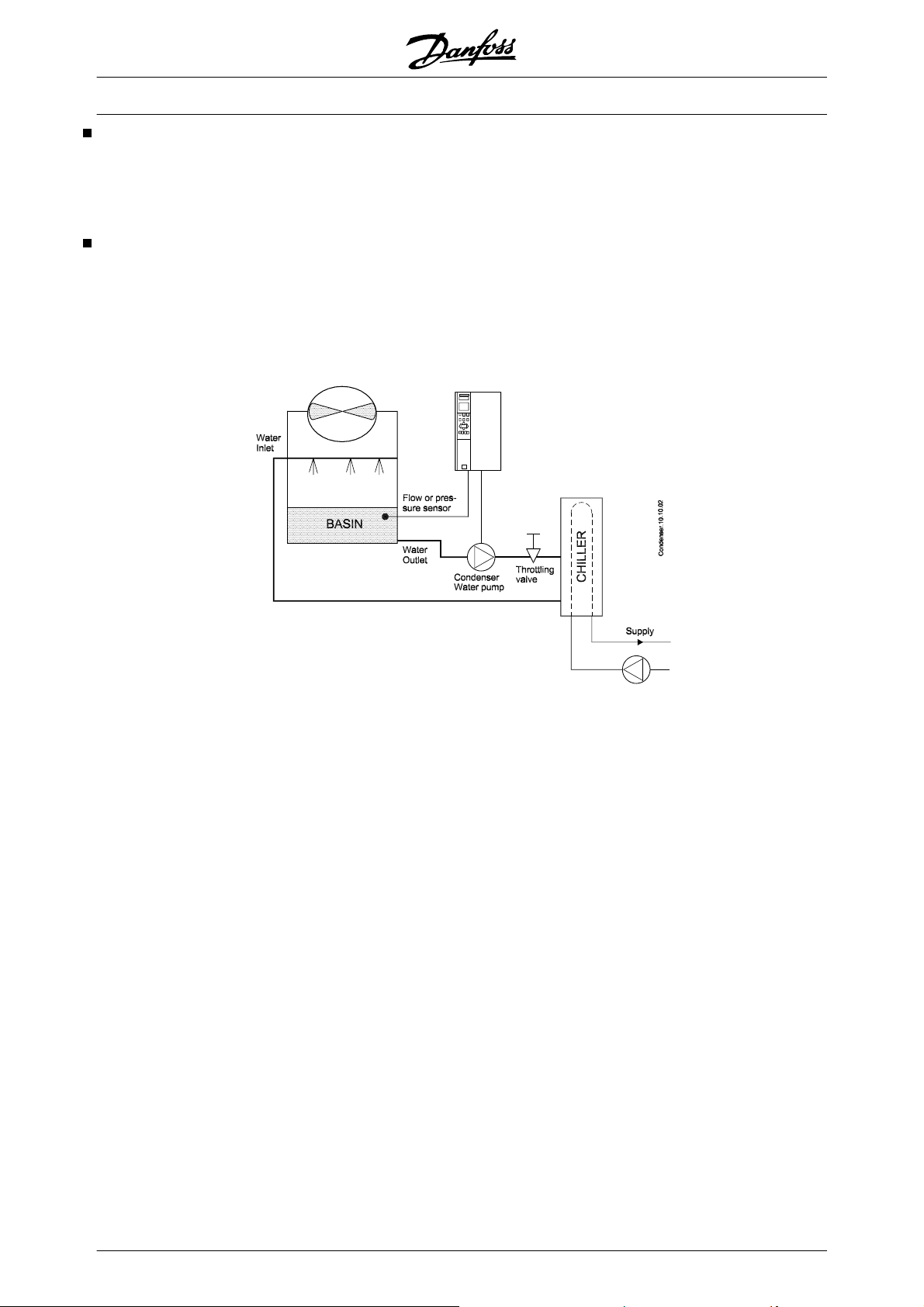
Condenser pumps
Condenser Water pumps are primarily used to circulate water through the condenser section of water cooled
chillers and their associated cooling tower. The condenser water absorbs the heat from the chiller's condenser
section and releases it into the atmosphere in the cooling tower. These systems are used to provide the most
efficient means of creating chilled water, they are as much as 20% more efficient than air cooled chillers.
The VLT solution
Frequency converters can be added to condenser water pumps instead of balancing the pumps with a throttling
valve or trimming the pump impeller.
Using a frequency converter instead of a throttling valve simply saves the energy that would have been absorbed
by the valve. This can amount to savings of 15-20% or more. Trimming the pump impeller is irreversible, thus if
the conditions change and higher flow is required the impeller must be replaced.
22 MG.61.B6.02 - VLT
®
is a registered Danfoss trademark
®
VLT
6000 HVAC Series
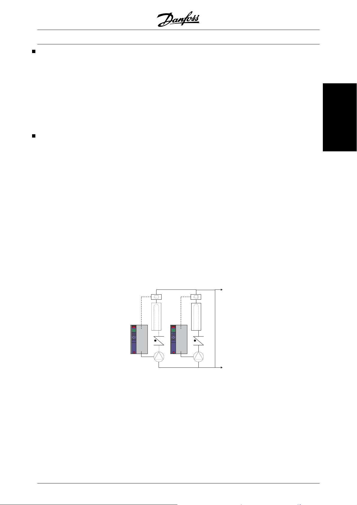
Primary pumps
Primary pumps in a primary/secondary pumping system can be used to maintain a constant flow through devices
that encounter operation or control difficulties when exposed to variable flow. The primary/ secondary pumping
technique decouples the “primary” production loop from the “secondary” distribution loop. This allows devices such
as chillers to obtain constant design flow and operate properly while allowing the rest of the system to vary in flow.
As the evaporator flow rate decreases in a chiller, the chilled water begins to become over-chilled. As this happens,
the chiller attempts to decrease its cooling capacity. If the flow rate drops far enough, or too quickly, the chiller
cannot shed its load sufficiently and the chiller’s low evaporator temperature safety trips the chiller requiring a
manual reset. This situation is common in large installations especially when two or more chillers in parallel are
installed if primary/ secondary pumping is not utilized.
The VLT solution
Depending on the size of the system and the size of the primary loop, the energy consumption of the primary loop
can become substantial.
A frequency converter can be added to the primary system, to replace the throttling valve and/or trimming of the
impellers, leading to reduced operating expenses. Two control methods are common:
The first method uses a flow meter. Because the desired flow rate is known and is constant, a flow meter installed
at the discharge of each chiller, can be used to control the pump directly. Using the built-in PID controller, the
frequency converter will always maintain the appropriate flow rate, even compensating for the changing resistance
in the primary piping loop as chillers and their pumps are staged on and off.
Introduction to HVAC
The other method is local speed determination. The operator simply decreases the output frequency until the
design flow rate is achieved.
Using a frequency converter to decrease the pump speed is very similar to trimming the pump impeller, except it
doesn’t require any labor and the pump efficiency remains higher. The balancing contractor simply decreases the
speed of the pump until the proper flow rate is achieved and leaves the speed fixed. The pump will operate at this
speed any time the chiller is staged on. Because the primary loop doesn’t have control valves or other devices
that can cause the system curve to change and the variance due to staging pumps and chillers on and off is usually
small, this fixed speed will remain appropriate. In the event the flow rate needs to be increased later in the systems
life, the frequency converter can simply increase the pump speed instead of requiring a new pump impeller.
Flowmeter
F
CHILLER
Flowmeter
F
CHILLER
MG.61.B6.02 - VLT
®
is a registered Danfoss trademark 23
®
VLT
6000 HVAC Series
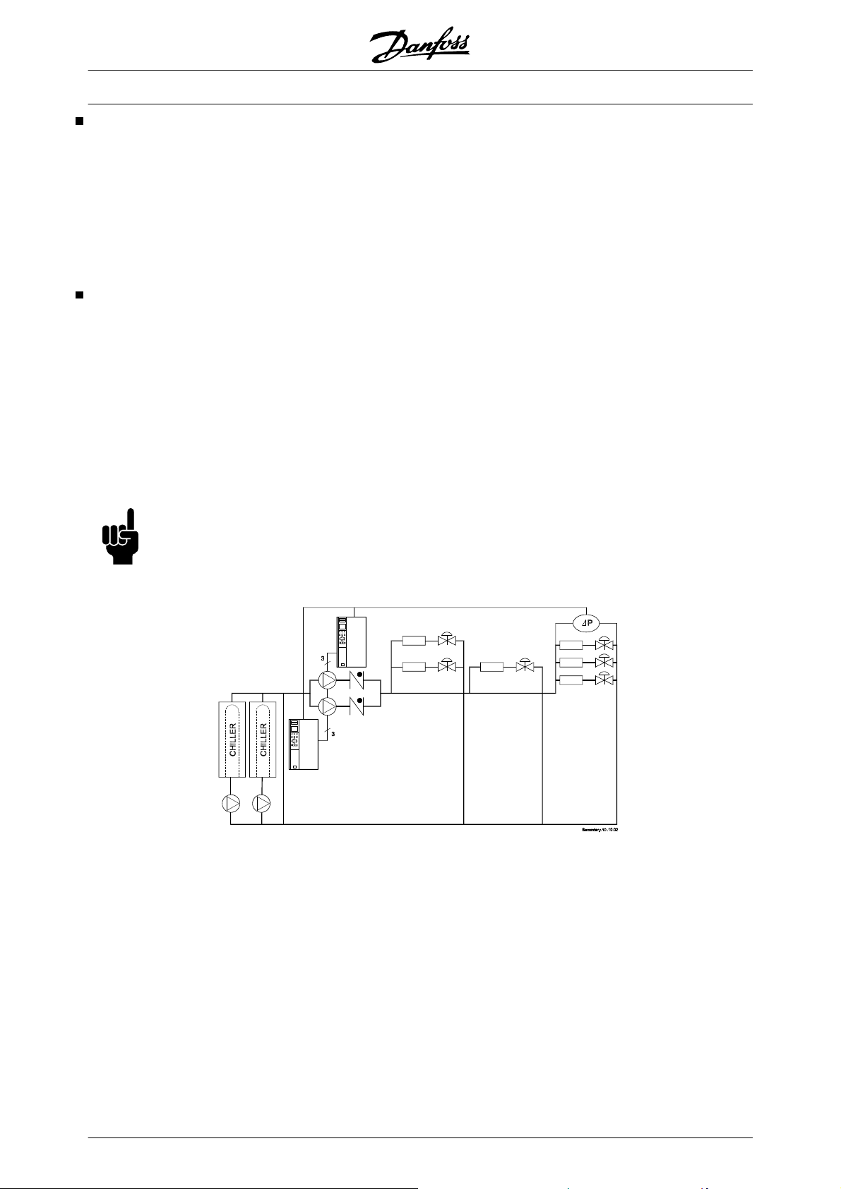
Secondary pumps
Secondary pumps in a primary/secondary chilled water pumping system are used to distribute the chilled water to
the loads from the primary production loop. The primary/secondary pumping system is used to hydronically decouple one piping loop from another. In this case. The primary pump is used to maintain a constant flow through
the chillers while allowing the secondary pumps to vary in flow, increase control and save energy.
If the primary/secondary design concept is not used and a variable volume system is designed, when the flow rate
drops far enough or too quickly, the chiller cannot shed its load properly. The chiller’s low evaporator temperature
safety then trips the chiller requiring a manual reset. This situation is common in large installations especially when
two or more chillers in parallel are installed.
The VLT solution
While the primary-secondary system with two-way valves improves energy savings and eases system control
problems, the true energy savings and control potential is realized by adding frequency converters.
With the proper sensor location, the addition of frequency converters allows the pumps to vary their speed to follow
the system curve instead of the pump curve.
This results in the elimination of wasted energy and eliminates most of the over-pressurization, two-way valves
can be subjected too.
As the monitored loads are reached, the two-way valves close down. This increases the differential pressure
measured across the load and two-way valve. As this differential pressure starts to rise, the pump is slowed to
maintain the control head also called setpoint value. This set-point value is calculated by summing the pressure
drop of the load and two way valve together under design conditions.
NB!
Please note that when running multiple pumps in parallel, they must run at the same speed to maximize
energy savings, either with individual dedicated drives or one frequency converter running multiple
pumps in parallel.
24 MG.61.B6.02 - VLT
®
is a registered Danfoss trademark
VLT
®
6000 HVAC Series
Choice of frequency converter
The frequency converter should be chosen on the basis of the given motor current at maximum load on the
system. The rated output current I
must be equal
VLT,N
Choose mains voltage for 50/60 Hz:
- 200-240 V three-phase AC voltage
- 380-460 V three-phase AC voltage
- 525-600 V three-phase AC voltage
to or higher than the required motor current.
VLT 6000 HVAC is available for three mains voltage
ranges: 200-240 V, 380-460 V, and 525-600 V.
Mains voltage 200 - 240 V
Typical shaft output
P
VLT type [kW] [HP] [A] [kVA]
6002
6003 1.5 2.0 7.5 3.1
6004 2.2 3.0 10.6 4.4
6005 3.0 4.0 12.5 5.2
6006 4.0 5.0 16.7 6.9
6008 5.5 7.5 24.2 10.1
6011 7.5 10 30.8 12.8
6016 11 15 46.2 19.1
6022 15 20 59.4 24.7
6027 18.5 25 74.8 31.1
6032 22 30 88.0 36.6
6042 30 40 115/104* 43.2
6052 37 50 143/130* 54.0
6062 45 60 170/154* 64.0
*The first figure is for a motor voltage of 200-230 V.
The next figure is for a motor voltage of 231-240 V.
VLT,N
1.1 1.5 6.6 2.7
Max continuous output current Max continuous output power
I
VLT,N
at 240 V S
VLT,N
Introduction to HVAC
Mains voltage 380 - 415 V
VLT type [kW] [A] [kVA]
6002
6003 1.5 4.1 2.9
6004 2.2 5.6 4.0
6005 3.0 7.2 5.2
6006 4.0 10.0 7.2
6008 5.5 13.0 9.3
6011 7.5 16.0 11.5
6016 11 24.0 17.3
6022 15 32.0 23.0
6027 18.5 37.5 27.0
6032 22 44.0 31.6
6042 30 61.0 43.8
6052 37 73.0 52.5
6062 45 90.0 64.7
6072 55 106 73.4
6102 75 147 102
6122 90 177 123
6152 110 212 147
6172 132 260 180
6222 160 315 218
6272 200 395 274
6352 250 480 333
6402 315 600 416
6502 355 658 456
6552 400 745 516
6602 450 800 554
Typical shaft output Max continuous output current Max continuous output power
P
VLT.N
1.1 3.0 2.2
I
VLT.N
at 400 V S
VLT.N
MG.61.B6.02 - VLT
®
is a registered Danfoss trademark 25
®
VLT
6000 HVAC Series
Mains voltage 440-460 V
Typical shaft output Max continuous output current Max continuous output power
P
VLT.N
I
VLT.N
at 460 V S
VLT type [HP] [ A] [kVA]
6002
1.5 3.0 2.4
6003 2.0 3.4 2.7
6004 3.0 4.8 3.8
6005 - 6.3 5.0
6006 5.0 8.2 6.5
6008 7.5 11.0 8.8
6011 10 14.0 11.2
6016 15 21.0 16.7
6022 20 27.0 21.5
6027 25 34.0 27.1
6032 30 40.0 31.9
6042 40 52.0 41.4
6052 50 65.0 51.8
6062 60 77.0 61.3
6072 75 106 84.5
6102 100 130 104
6122 125 160 127
6152 150 190 151
6172 200 240 191
6222 250 302 241
6272 300 361 288
6352 350 443 353
6402 450 540 430
6502 500 590 470
6552 600 678 540
6602 600 730 582
VLT.N
Mains voltage 525 V
Typical shaft output Max. constant output current, 525 V Max. constant output power
P
VLT.N
I
VLT.N
at 525 V S
VLT type [kW] [ A] [kVA]
6002
1.1 2.6 2.3
6003 1.5 2.9 2.5
6004 2.2 4.1 3.6
6005 3.0 5.2 4.5
6006 4.0 6.4 5.5
6008 5.5 9.5 8.2
6011 7.5 11.5 10.0
6016 11 18 15.6
6022 15 23 20
6027 18.5 28 24
6032 22 34 29
6042 30 43 37
6052 37 54 47
6062 45 65 56
6072 55 81 70
6102 75 113 98
6122 90 137 119
6152 110 162 140
6172 132 201 174
6222 160 253 219
6272 200 303 262
6352 250 360 312
6402 315 418 362
6502 400 523 498
6602 450 596 568
6652 500 630 600
VLT.N
26 MG.61.B6.02 - VLT
®
is a registered Danfoss trademark

®
VLT
Mains voltage 575 - 600 V
VLT type [kW] [ A] [kVA]
6002
6003 1.5 2.7 2.7
6004 2.2 3.9 3.9
6005 3.0 4.9 4.9
6006 4.0 6.1 6.1
6008 5.5 9 9.0
6011 7.5 11 11.0
6016 11 17 16.9
6022 15 22 22
6027 18.5 27 27
6032 22 32 32
6042 30 41 41
6052 37 52 52
6062 45 62 62
6072 55 77 77
6102 75 108 108
6122 90 131 130
6152 110 155 154
6172 132 192 289
6222 160 242 241
6272 200 290 288
6352 250 344 343
6402 315 400 398
6502 400 500 498
6602 450 570 568
6652 500 630 627
Typical shaft output Max. constant output current, 575 V Max. constant output kVA,
P
VLT.N
1.1 2.4 2.4
I
VLT.N
6000 HVAC Series
S
575
VLT.N
Introduction to HVAC
MG.61.B6.02 - VLT
®
is a registered Danfoss trademark 27
VLT
®
6000 HVAC Series
Unpacking and ordering a VLT frequency converter
If you are in doubt as to which frequency converter you
have received and which options it contains, use the
following to find out.
Type code ordering number string
On the basis of your order, the frequency converter is
given an ordering number that can be seen from the
nameplate on the unit. The number may look as follows:
VLT-6008-H-T4-B20-R3-DL-F10-A00-C0
This means that the frequency converter ordered is a
VLT 6008 for three-phase mains voltage of 380-460 V
(T4) in Bookstyle enclosure IP 20 (B20). The hardware
variant is with integral RFI filter, classes A & B (R3).
The frequency converter features a control unit (DL)
with a PROFIBUS option card (F10). No option card
(A00) and no conformal coating (C0) Character no. 8
( H) indicates the application range of the unit: H =
HVAC.
IP 00: This enclosure is only available for the larger
power sizes of the VLT 6000 HVAC series. It is recommended for installation in standard cabinets.
IP 20 Bookstyle: This enclosure is designed for cabinet
installation. It takes up a minimum of space and can
be fitted side-by-side without installation of extra cooling equipment.
IP 20/NEMA 1: This enclosure is used as standard enclosure for VLT 6000 HVAC. It is ideal for cabinet
installation in areas where a high degree of protection
is required. This enclose also permits side-by-side installation.
IP 54: This enclosure can be fitted direct to the wall.
Cabinets are not required. IP 54 units can also be installed side-by-side.
Hardware variant
The units in the programme are available in the following hardware variants:
ST: Standard unit with or without control unit. With-
out DC terminals, except for
VLT 6042-6062, 200-240 V
VLT 6016-6072, 525-600 V
SL: Standard unit with DC terminals.
EX: Extended unit with control unit, DC terminals,
connection of external 24 V DC supply for back-
up of control PCB.
DX: Extended unit with control unit, DC terminals,
built-in mains fuses and disconnector, connec-
tion of external 24 V DC supply for back-up of
control PCB.
PF: Standard unit with 24 V DC supply for back-up
of control PCB and built-in main fuses. No DC
terminals.
PS: Standard unit with 24 V DC supply for back-up
of control PCB. No DC terminals.
PD: Standard unit with 24 V DC supply for back-up
of control PCB, built-in main fuses and discon-
nect. No DC terminals.
RFI filter
Bookstyle units always come with an integral RFI filter that complies with EN 55011-B with 20 m
screened/armoured motor cable and EN 55011-A1
with 150 m screened/armoured motor cable. Units for
mains voltage of 240 V and a motor power of up to
and including 3.0 kW (VLT 6005) and units for a mains
voltage of 380-460 V and a motor power of up to 7.5
kW (VLT 6011) are always supplied with an integral
class A1 & B filter. Units for higher motor power than
these (3.0 and 7.5 kW, respectively) can be ordered
either with or without an RFI filter.
Control unit (keypad and display)
All types of units in the programme, except for IP21
VLT 6402-6602, 380-460 V, VLT 6502-6652, 525-600
V and IP 54 units, can be ordered either with or without the control unit. IP 54 units always come with a
control unit. All types of units in the programme are
available with built-in application options including a
relay card with four relays or a cascade controller
card.
Conformal Coating
All types of units in the programme are available with
or without conformal coating of the PCB.
VLT 6402-6602, 380-460 V and VLT 6102-6652,
525-600 V are only available coated.
28 MG.61.B6.02 - VLT
®
is a registered Danfoss trademark
®
VLT
6000 HVAC Series
200-240 V
Typecode
Position in string
1.1 kW/1.5 HP 6002 X X X X X
1.5 kW/2.0 HP 6003 X X X X X
2.2 kW/3.0 HP 6004 X X X X X
3.0 kW/4.0 HP 6005 X X X X X
4.0 kW/5.0 HP 6006 X X X X X X
5.5 kW/7.5 HP 6008 X X X X X X
7.5 kW/10 HP 6011 X X X X X X
11 kW/15 HP 6016 X X X X X X
15 kW/20 HP 6022 X X X X X X
18.5 kW/25 HP 6027 X X X X X X
22 kW/30 HP 6032 X X X X X X
30 kW/40 HP 6042 X X X X X X
37 kW/50 HP 6052 X X X X X X
45 kW/60 HP 6062 X XXX XX
T2
9-10
C00
11-13
B20
11-13
C20
11-13
CN1
11-13
C54
11-13ST14-15SL14-15R016-17R116-17R316-17
380-460 V
Typecode
Position in string
T4
9-10
1.1 kW/1.5 HP 6002 X X X X X
1.5 kW/2.0 HP 6003 X X X X X
2.2 kW/3.0 HP 6004 X X X X X
3.0 kW/4.0 HP 6005 X X X X X
4.0 kW/5.0 HP 6006 X X X X X
5.5 kW/7.5 HP 6008 X X X X X
7.5 kW/10 HP 6011 X X X X X
11 kW/15 HP 6016 X X X X X X
15 kW/20 HP 6022 X X X X X X
18.5 kW/25 HP 6027 X X X X X X
22 kW/30 HP 6032 X X X X X X
30 kW/40 HP 6042 X X X X X X
37 kW/50 HP 6052 X X X X X X
45 kW/60 HP 6062 X X X X X X
55 kW/75 HP 6072 X X X X X X
75 kW/100 HP 6102 X X X X X X
90 kW/125 HP 6122 X X X X X X
110 kW/150 HP 6152 X X X X X X X X X X X
132 kW/200 HP 6172 X X X X X X X X X X X
160 kW/250 HP 6222 X X X X X X X X X X X
200 kW/300 HP 6272 X X X X X X X X X X X
250 kW/350 HP 6352 X X X X X X X X X X X
315 kW/450 HP 6402 X X X X X X X X X X X
355 kW/500 HP 6502 X X X X X X X X X X X
400 kW/550 HP 6552 X X X X X X X X X X X
450 kW/600 HP 6602 X XXX XXXXXXX
C00
11-13
B20
11-1
3
C20
11-1
3
CN1
11-1
3
C54
11-13
ST
14-1
5
SL
14-1
5
EX
14-15
DX
14-1
5
PS
14-1
5
PD
14-15
PF
14-1
5
R0
16-1
7
R1
16-17
R3
16-1
7
Introduction to HVAC
Voltage
T2: 200-240 VAC
T4: 380-460 VAC
Enclosure
C00: Compact IP 00
B20: Bookstyle IP 20
NB!
NEMA 1 exceeds IP 20
MG.61.B6.02 - VLT
C20: Compact IP 20
CN1: Compact NEMA 1
C54: Compact IP 54
Hardware variant
ST: Standard
SL: Standard with DC terminals
EX: Extended with 24 V supply and DC terminals
DX: Extended with 24 V supply, DC terminals, disconnect and fuse
®
is a registered Danfoss trademark 29
PS: Standard with 24 V supply
PD: Standard with 24 V supply, fuse and disconnect
PF: Standard with 24 V supply and fuse
RFI filter
R0: Without filter
R1: Class A1 filter
R3: Class A1 and B filter

®
VLT
6000 HVAC Series
525-600 V
Typecode
Position in string
1.1 kW/1.5 HP 6002 X X X X
1.5 kW/2.0 HP 6003 X X X X
2.2 kW/3.0 HP 6004 X X X X
3.0 kW/4.0 HP 6005 X X X X
4.0 kW/5.0 HP 6006 X X X X
5.5 kW/7.5 HP 6008 X X X X
7.5 kW/10 HP 6011 X X X X
11 kW/15 HP 6016 X X X
15 kW/20 HP 6022 X X X
18.5 kW/25 HP 6027 X X X
22 kW/30 HP 6032 X X X
30 kW/40 HP 6042 X X X
37 kW/50 HP 6052 X X X
45 kW/60 HP 6062 X X X
55 kW/75 HP 6072 XX X
T6
9-10
C00
11-13
C20
11-13
CN1
11-13
ST
14-15
R0
16-17
VLT 6102-6652, 525-600 V
Typecode
Position in stringT69-10
75 kW / 100 HP 6102 X X X X X X X X X X
90 kW / 125 HP 6122 X X X X X X X X X X
110 kW / 150 HP 6152 X X X X X X X X X X
132 kW / 200 HP 6172 X X X X X X X X X X
160 kW / 250 HP 6222 X X X X X X X X X X
200 kW / 300 HP 6272 X X X X X X X X X X
250 kW / 350 HP 6352 X X X X X X X X X X
315 kW / 400 HP 6402 X X X X X X X X X X
400 kW / 500 HP 6502 X X X X X X X X X X X
450 kW / 600 HP 6602 X X X X X X X X X X X
500 kW / 650 HP 6652 XXXXXXX X XXX
C00
11-13
CN1
11-13
C54
11-13ST14-15EX14-15DX14-15PS14-15PD14-15PF14-15R016-17R116-17
1)
X
1)
X
1)
X
1)
X
1)
X
1)
X
1)
X
1)
X
1) R1 is not available with DX, PF, PD options.
NB!
NEMA 1 exceeds IP 20
Voltage
T6: 525-600 VAC
Enclosure
C00: Compact IP 00
C20: Compact IP 20
CN1: Compact NEMA 1
C54: Compact IP 54
Hardware variant
ST: Standard
EX: Extended with 24 V supply and DC terminals
DX: Extended with 24 V supply, DC terminals, disconnect and fuse
PS: Standard with 24 V supply
PD: Standard with 24 V supply, fuse and disconnect
PF: Standard with 24 V supply and fuse
RFI filter
R0: Without filter
R1: Class A1 filter
30 MG.61.B6.02 - VLT
®
is a registered Danfoss trademark

Optional selections, 200-600 V
VLT
®
6000 HVAC Series
Display
1)
Without LCP
D0
DL With LCP
Fieldbus option
F00 No options
F10 Profibus DP V1
F13 Profibus FMS
F30 DeviceNet
F40 LonWorks free topology
F41 LonWorks 78 kBps
F42 LonWorks 1.25 MBps
Application option
A00 No options
2)
Relay card 4 relays
A31
A32 Cascade Controller
A40 Real Time Clock
Coating
3)
No coating
C0
C1 With coating
1) Not available with enclosure compact IP 54
2) Not available with fieldbus options (Fxx)
3) Not available for power sizes from 6402 to 6602, 380-460 V and
6102-6652, 525-600 V
Position: 18-19
Position: 20-22
Position: 23-25
Position: 26-27
Introduction to HVAC
MG.61.B6.02 - VLT
®
is a registered Danfoss trademark 31

Ordering form
VLT
®
6000 HVAC Series
32 MG.61.B6.02 - VLT
®
is a registered Danfoss trademark

VLT
®
6000 HVAC Series
PC software and serial communication
Danfoss offers various options for serial communication. Using serial communication, it is possible to monitor, program and control one or several frequency
converters from a centrally located computer.
All VLT 6000 HVAC units have a RS 485 port as standard with a choice of three protocols. The three protocols selectable in parameter 500 Protocols are:
• FC protocol
• Johnson Controls Metasys N2
• Landis/Staefa Apogee FLN
• Modbus RTU
A bus option card allows higher transmission speed
than RS 485. In addition, a higher number of units can
be linked to the bus and alternative transmission media can be used. Danfoss offers the following option
cards for communication:
• Profibus
• LonWorks
• DeviceNet
MCT 10 has been designed as an easy to use interactive tool for setting parameters in our frequency
converters.
The MCT 10 Set-up Software will be useful for:
• Planning a communication network off-line.
MCT 10 contains a complete frequency converter database
• Commissioning frequency converters on line
• Saving settings for all frequency converters
• Replacing a drive in a network
• Expanding an existing network
• Future developed drives will be supported
MCT 10 Set-up Software support Profibus DP-V1 via
a Master class 2 connection. It makes it possible to on
line read/write parameters in a frequency converter via
the Profibus network. This will eliminate the need for
an extra communication network.
The MCT 10 Set-up Software Modules
The following modules are included in the software
package:
Introduction to HVAC
Information on the installation of various options is not
included in this Design Guide.
PC Software tools
PC Software - MCT 10
All drives are equipped with a serial communication
port. We provide a PC tool for communication between
PC and frequency converter, VLT Motion Control Tool
MCT 10 Set-up Software.
MCT 10 Set-up Software
MCT 31
The MCT 31 harmonic calculation PC tool enables
easy estimation of the harmonic distortion in a given
application. Both the harmonic distortion of Danfoss
frequency converters as well as non-Danfoss frequency converters with different additional harmonic reduc-
MCT 10 Set-up Software
Setting parameters
Copy to and from frequency converters
Documentation and print out of parameter settings incl. diagrams
SyncPos
Creating SyncPos programme
Ordering number:
Please order your CD containing MCT 10 Set-up Software using code number 130B1000.
tion measurements, such as Danfoss AHF filters and
12-18-pulse rectifiers, can be calculated.
Ordering number:
Please order your CD containing the MCT 31 PC tool
using code number 130B1031.
Fieldbus options
The increasing need for information in building management systems makes it necessary to collect or
visualise many different types of process data.
Important process data can help the system technician
in the day to day monitoring of the system, which
MG.61.B6.02 - VLT
®
is a registered Danfoss trademark 33
means that a negative development, e. g. an increase
in energy consumption, can be rectified in time.
The substantial amount of data in large buildings may
generate a need for a higher transmission speed than
9600 baud.

VLT
®
6000 HVAC Series
Profibus
Profibus is a fieldbus system with FMS and DP, which
can be used for linking automation units, such as sensors and actuators, to the controls by means of a twoconductor cable.
Profibus FMS is used if major communication tasks
are to be solved at cell and system level by means of
large volumes of data.
Profibus DP is an extremely fast communication protocol, made specially for communication between the
automation system and various units.
LON - Local Operating Network
LonWorks is an intelligent fieldbus system which improves the possibility of decentralising control, as communication is enabled between individual units in the
same system (Peer-to-Peer).
This means that there is no need for a big main station
for handling all the signals of the system (MasterSlave). Signals are sent direct to the unit that needs
them via a common network medium. This makes
communication much more flexible and the central
building state control and monitoring system can be
changed into a dedicated building state monitoring
system whose task is to ensure that everything is running as planned. If the potential of LonWorks is fully
utilised, sensors will also be connected to the bus,
which means that a sensor signal can quickly be
moved to another controller. If room dividers are mobile, this is a particularly useful feature.
used to establish master-slave/client-server communication between intelligent devices.
MODBUS is used to monitor and program devices; to
communicate intelligent devices with sensors and instruments; to monitor field devices using PCs and
HMIs.
MODBUS is often applied in Gas and Oil applications,
but also in building, infrastructure, transportation and
energy, applications are making use of its benefits.
Accessories for VLT 6000 HVAC
IP 20 bottom cover
DeviceNet
DeviceNet is a digital, multi-drop network, based on
the CAN protocol, that connects and serves as a communication network between industrial controllers and
I/O devices.
Each device and/or controller is a node on the network.
DeviceNet is a producer-consumer network that supports multiple communication hierarchies and message prioritization.
DeviceNet systems can be configured to operate in a
master-slave or a distributed control architecture using
peer-to-peer communication. This system offers a single point of connection for configuration and control by
supporting both I/O and explicit messaging.
DeviceNet also has the feature of having power on the
network. This allows devices with limited power requirements to be powered directly from the network via
the 5-conductor cable.
Modbus RTU
MODBUS RTU (Remote Terminal Unit) Protocol is a
messaging structure developed by Modicon in 1979,
Application option
34 MG.61.B6.02 - VLT
®
is a registered Danfoss trademark

®
VLT
6000 HVAC Series
Ordering numbers, misc.
Type Description Order no.
IP 4x top cover
IP 4x top cover IP
IP 4 x top cover
NEMA 12 bonding plate
NEMA 12 bonding plate
IP 20 terminal cover Option, VLT type 6006-6022 200-240 V 175Z4622
IP 20 terminal cover Option, VLT type 6027-6032 200-240 V 175Z4623
IP 20 terminal cover Option, VLT type 6016-6042 380-460 V 175Z4622
IP 20 terminal cover Option, VLT type 6016-6042 525-600 V 175Z4622
IP 20 terminal cover Option, VLT type 6052-6072 380-460 V 175Z4623
IP 20 terminal cover Option, VLT type 6102-6122 380-460 V 175Z4280
IP 20 terminal cover Option, VLT type 6052-6072 525-600 V 175Z4623
IP 20 bottom cover Option, VLT type 6042-6062 200-240 V 176F1800
Terminal adaptor kit VLT type 6042-6062 200-240 V, IP 54 176F1808
Terminal adaptor kit VLT type 6042-6062 200-240 V, IP 20/NEMA 1 176F1805
Control panel LCP Separate LCP 175Z7804
LCP remote-mounting kit IP 00 & 20
LCP remote-mounting kit IP 54
LCP blind cover for all IP00/IP20 drives 175Z7806
Cable for LCP Separate cable, 3 m 175Z0929
Relay card Application card with four relay outputs 175Z7803
Cascade controller card With conformal coating 175Z3100
Real Time Clock Option Without/with conformal coating 175Z4852/175Z4853
Profibus option Without/with conformal coating 175Z7800/175Z2905
LonWorks option, Free topology Without/with conformal coating 176F1515/176F1521
LonWorks option, 78 KBPS Without/with conformal coating 176F1516/176F1522
LonWorks option, 1.25 MBPS Without/with conformal coating 176F1517/176F1523
Modbus RTU option Without conformal coating 175Z3362
DeviceNet option Without/with conformal coating 176F1586/176F1587
MCT 10 Set-up software CD-Rom 130B1000
MCT 31 Harmonic calculation CD-Rom 130B1031
1)
1)
1)
2)
2)
3)
4)
Option, VLT type 6002-6005 200-240 V compact 175Z0928
Option, VLT type 6002-6011 380-460 V compact 175Z0928
Option, VLT type 6002-6011 525-600 V compact 175Z0928
Option, VLT type 6002-6005 200-240 V 175H4195
Option, VLT type 6002-6011 380-460 V 175H4195
Remote-mounting kit, incl. 3 m cable
Remote-mounting kit, incl. 3 m cable 175Z7802
175Z0850
Rittal Installation Kit
Introduction to HVAC
Type
Rittal TS8 enclosure for IP00
Description Order No.
5)
Installation kit for 1800mm high enclosure, VLT6152-6172,
176F1824
380-460V, VLT 6102-6172, 525-600 V
Rittal TS8 enclosure for IP00
Installation kit for 2000mm high enclosure, VLT6152-6172,
176F1826
5)
380-460V, VLT 6102-6172, 525-600 V
Rittal TS8 enclosure for IP00
Installation kit for 1800mm high enclosure, VLT6222-6352,
176F1823
5)
380-460V, VLT 6222-6402, 525-600 V
Rittal TS8 enclosure for IP00
Installation kit for 2000mm high enclosure, VLT6222-6352,
176F1825
5)
380-460V, VLT 6222-6402, 525-600 V
Rittal TS8 enclosure for IP00
Installation kit for 2000mm high enclosure, VLT6402-6602,
176F1850
5)
380-460V and VLT 6502-6652, 525-600 V
Floor stand for IP21 and IP54
enclosure
5)
Mains shield kit Protection kit: for VLT 6152-6352, 380-460V, VLT
Option, VLT6152-6352, 380-460V, VLT 6102-6402,
525-600 V
176F1827
176F0799
6102-6402, 525-600V
Mains shield kit Protection kit for VLT 6402-6602, 380-460V; VLT
176F1851
6502-6652, 525-600 V
1) IP 4x/NEMA 1 top cover is for IP 20 units only and only horizontal surfaces comply with IP 4x. The kit also
contains a bonding plate (UL).
2) NEMA 12 bonding plate (UL) is only for IP 54 units.
3) The remote-mounting kit is only for IP 00 and IP 20 units. Enclosure of the remote-mounting kit is IP 65.
4) The remote-mounting kit is only for IP 54 units. Enclosure of the remote-mounting kit is IP 65.
5) For details: See High Power Installation Guide, MI.90.JX.YY.
VLT 6000 HVAC is available with an integral fieldbus
option or application option. Ordering numbers for the
individual VLT types with integrated options can be
MG.61.B6.02 - VLT
®
is a registered Danfoss trademark 35
seen from the relevant manuals or instructions. In addition, the ordering number system can be used for
ordering a frequency converter with an option.

Output Filters
The high speed switching of the frequency converter
produces some secondary effects, which influence the
motor and the enclosed environment. These side effects are addressed by two different filter types, -the
du/dt and the Sine-wave filter.
dU/dt filters
Motor insulation stresses are often caused by the combination of rapid voltage and current increase. The
rapid energy changes can also be reflected back to the
DC-line in the inverter and cause shut down. The du/
dt filter is designed to reduce the voltage rise time/the
rapid energy change in the motor and by that intervention avoid premature aging and flashover in the
motor insulation. du/dt filters have a positive influence
on the radiation of magnetic noise in the cable that
connects the drive to the motor. The voltage wave form
is still pulse shaped but the du/dt ratio is reduced in
comparison with the installation without filter.
®
VLT
6000 HVAC Series
Sine-wave filters
Sine-wave filters are designed to let only low frequencies pass. High frequencies are consequently shunted
away which results in a sinusoidal phase to phase
voltage waveform and sinusoidal current waveforms.
With the sinusoidal waveforms the use of special frequency converter motors with reinforced insulation is
no longer needed. The acoustic noise from the motor
is also damped as a consequence of the wave condition.
Besides the features of the du/dt filter, the sine-wave
filter also reduces insulation stress and bearing currents in the motor thus leading to prolonged motor
lifetime and longer periods between services. Sinewave filters enable use of longer motor cables in applications where the motor is installed far from the
drive. The length is unfortunately limited because the
filter does not reduce leakage currents in the cables.
Ordering Numbers: Sine Wave Filter Modules,
200-500 VAC
Mains supply 3 x 200 to 500 V
Minimum switching frequency
5 kHz 120 Hz 130B2439 130B2404 2.5 A
5 kHz 120 Hz 130B2441 130B2406 4.5 A
5 kHz 120 Hz 130B2443 130B2408 8 A
5 kHz 120 Hz 130B2444 130B2409 10 A
5 kHz 120 Hz 130B2446 130B2411 17 A
4 kHz 60 Hz 130B2447 130B2412 24 A
4 kHz 60 Hz 130B2448 130B2413 38 A
4 kHz 60 Hz 130B2307 130B2281 48 A
3 kHz 60 Hz 130B2308 130B2282 62 A
3 kHz 60 Hz 130B2309 130B2283 75 A
3 kHz 60 Hz 130B2310 130B2284 115 A
3 kHz 60 Hz 130B2311 130B2285 180 A
3 kHz 60 Hz 130B2312 130B2286 260 A
3 kHz 60 Hz 130B2313 130B2287 410 A
3 kHz 60 Hz 130B2314 130B2288 480 A
2 kHz 60 Hz 130B2315 130B2289 660 A
2 kHz 60 Hz 130B2316 130B2290 750 A
2 kHz 60 Hz 130B2317 130B2291 880 A
2 kHz 60 Hz 130B2318 130B2292 1200 A
Maximum output fre-
quency
NB!
When using Sine-wave filters, the switching frequency should comply with filter specifications in par.
411 Switching Frequency.
Part No. IP20 Part No. IP00 Rated filter current at 50Hz
36 MG.61.B6.02 - VLT
®
is a registered Danfoss trademark

VLT
Ordering Numbers: Sine-Wave Filter Modules, 525-600 VAC
Mains supply 3 x 525 to 690 V
Minimum switching frequency
2 kHz 60 Hz 130B2341 130B2321 13 A
2 kHz 60 Hz 130B2342 130B2322 28 A
2 kHz 60 Hz 130B2343 130B2323 45 A
2 kHz 60 Hz 130B2344 130B2324 76 A
2 kHz 60 Hz 130B2345 130B2325 115 A
2 kHz 60 Hz 130B2346 130B2326 165 A
2 kHz 60 Hz 130B2347 130B2327 260 A
2 kHz 60 Hz 130B2348 130B2329 303 A
1.5 kHz 60 Hz 130B2270 130B2241 430 A
1.5 kHz 60 Hz 130B2271 130B2242 530 A
1.5 kHz 60 Hz 130B2381 130B2337 660 A
1.5 kHz 60 Hz 130B2382 130B2338 765 A
1.5 kHz 60 Hz 130B2383 130B2339 940 A
1.5 kHz 60 Hz 130B2384 130B2340 1320 A
NB!
When using Sine-wave filters, the switching frequency should comply with filter specifications in par.
14-01 Switching Frequency.
Maximum output frequen-
cy
Part No. IP20 Part No. IP00
®
6000 HVAC Series
Rated filter current at
50Hz
Introduction to HVAC
Ordering Numbers: du/dt Filters, 380-480 VAC Mains supply 3x380 to 3x480 V
Minimum switching frequen-cyMaximum output frequen-
cy
Part No. IP20 Part No. IP00
Rated filter current at 50
4 kHz 60 Hz 130B2396 130B2385 24 A
4 kHz 60 Hz 130B2397 130B2386 45 A
3 kHz 60 Hz 130B2398 130B2387 75 A
3 kHz 60 Hz 130B2399 130B2388 110 A
3 kHz 60 Hz 130B2400 130B2389 182 A
3 kHz 60 Hz 130B2401 130B2390 280 A
3 kHz 60 Hz 130B2402 130B2391 400 A
3 kHz 60 Hz 130B2277 130B2275 500 A
2 kHz 60 Hz 130B2278 130B2276 750 A
2 kHz 60 Hz 130B2405 130B2393 910 A
2 kHz 60 Hz 130B2407 130B2394 1500 A
2 kHz 60 Hz 130B2410 130B2395 2300 A
Ordering Numbers: du/dt Filters, 525-600 VAC
Mains supply 3x525 to 3x600 V
Minimum switching frequen-cyMaximum output frequen-
cy
Part No. IP20 Part No. IP00
Rated filter current at 50
4 kHz 60 Hz 130B2423 130B2414 28 A
4 kHz 60 Hz 130B2424 130B2415 45 A
3 kHz 60 Hz 130B2425 130B2416 75 A
3 kHz 60 Hz 130B2426 130B2417 115 A
3 kHz 60 Hz 130B2427 130B2418 165 A
3 kHz 60 Hz 130B2428 130B2419 260 A
3 kHz 60 Hz 130B2429 130B2420 310 A
3 kHz 60 Hz 130B2278 130B2235 430 A
2 kHz 60 Hz 130B2239 130B2236 530 A
2 kHz 60 Hz 130B2274 130B2280 630 A
2 kHz 60 Hz 130B2430 130B2421 765 A
2 kHz 60 Hz 130B2431 130B2422 1350 A
Hz
Hz
MG.61.B6.02 - VLT
®
is a registered Danfoss trademark 37

Harmonic filter
Harmonic currents do not directly affect the electricity
consumption but has an impact on following conditions:
Higher total current to be handled by the installations
Increases load on transformer (sometimes it
-
will require a larger transformer, particular at
retrofit)
Increases heat losses in transformer and in-
-
stallation
In some cases demands larger cables,
-
switches and fuses
Higher voltage distortion due to higher current
Increase risk for disturbing electronic equip-
-
ment connected to same grid
A high percentage of rectifier load from eg frequency
converters, will increase the harmonic current, which
must be reduced to avoid the above consequences.
Therefore the frequency converter has as standard,
built in DC coils reducing the total current with about
40% (compared to devices without any arrangement
for harmonic suppression), down to 40-45% ThiD.
VLT
®
6000 HVAC Series
In some cases there is a need for further suppression
(eg retrofit with frequency converters). For this purpose Danfoss can offer two advanced harmonic filters
AHF05 and AHF10, bringing the harmonic current
down to around 5% and 10% respectively. For further
details see instruction MG.80.BX.YY.
38 MG.61.B6.02 - VLT
®
is a registered Danfoss trademark

VLT
®
6000 HVAC Series
Ordering numbers, Harmonic filters
Harmonic filters are used to reduce mains harmonics
380-415V, 50Hz
I
AHF,N
10 A 4, 5.5 175G6600 175G6622 6006, 6008
19 A 7.5 175G6601 175G6623 6011, 6016
26 A 11 175G6602 175G6624 6022
35 A 15, 18.5 175G6603 175G6625 6027
43 A 22 175G6604 175G6626 6032
72 A 30, 37 175G6605 175G6627 6042, 6052
101 A 45. 55 175G6606 175G6628 6062, 6072
144 A 75 175G6607 175G6629 6102
180 A 90 175G6608 175G6630 6122
217 A 110 175G6609 175G6631 6152
289 A 132, 160 175G6610 175G6632 6172, 6222
324 A 175G6611 175G6633
Higher ratings can be achieved by paralleling the filter units
370 A 200 175G6688 175G6691 6272
434 A
578 A 315 Two 289 A units 6402
613 A 355 289 A and 324 A units 6502
648 A 400 Two 324 A units 6552
740 A 450 Two 324 A units 6602
Typical Motor Used
[kW]
250 Two 217 A units 6352
Danfoss ordering number VLT 6000
AHF 005 AHF 010
• AHF 010: 10% current distortion
• AHF 005: 5% current distortion
Introduction to HVAC
MG.61.B6.02 - VLT
®
is a registered Danfoss trademark 39

440-480V, 60Hz
I
AHF,N
19 A 10, 15 175G6612 175G6634 6011, 6016
26 A 20 175G6613 175G6635 6022
35 A 25, 30 175G6614 175G6636 6027, 6032
43 A 40 175G6615 175G6637 6042
72 A 50, 60 175G6616 175G6638 6052, 6062
101 A 75 175G6617 175G6639 6072
144 A 100, 125 175G6618 175G6640 6102, 6122
180 A 150 175G6619 175G6641 6152
217 A 200 175G6620 175G6642 6172
289 A 250 175G6621 175G6643 6222
324 A 300 175F6689 175G6692 6272
Higher ratings can be achieved by paralleling the filter units
397 A 350 175G6690 175G6693 6352
506 A
578 A 500 Two 289 A units 6502
578 A 550 Two 289 A units 6552
648 A 600 Two 324 A units 6602
Typical Motor Used
[HP]
450 217 A and 289 A units 6402
Danfoss ordering number VLT 6000
AHF 005 AHF 010
Please note that the matching of the Danfoss frequency converter and filter is pre-calculated based on
400V/480V and assuming typical motor load (4 pole)
and 110 % torque. Regarding harmonic filters for
500-525V, please contact Danfoss or consult MG.
80.BX.YY.
For other combinations, please consult MG.80.BX.YY.
®
VLT
6000 HVAC Series
application. Both the harmonic distortion of Danfoss
frequency converters as well as non-Danfoss frequency converters with different additional harmonic reduction devices, such as Danfoss AHF filters and 12-18pulse rectifiers, can be calculated.
Ordering number:
Please order your CD containing the MCT 31 PC tool
using code number 130B1031.
MCT 31
The MCT 31 harmonic calculation PC tool enables
easy estimation of the harmonic distortion in a given
MCT 31 can also be downloaded from the Danfoss Internet: WWW.DANFOSS.COM, Business Area: Motion Controls.
40 MG.61.B6.02 - VLT
®
is a registered Danfoss trademark

®
VLT
Mains supply (L1, L2, L3)
Mains supply (L1, L2, L3):
Supply voltage 200-240 V units 3 x 200/208/220/230/240 V ±10%
Supply voltage 380-460 V units 3 x 380/400/415/440/460 V ±10%
Supply voltage 525-600 V units 3 x 525/550/575/600 V ±10%
Supply frequency 48-62 Hz ± 1%
Max. imbalance of supply voltage:
VLT 6002-6011, 380-460 V and 525-600 V and VLT 6002-6005, 200-240 V ±2.0% of rated supply voltage
VLT 6016-6072, 380-460 V and 525-600 V and VLT 6006-6032, 200-240 V ±1.5% of rated supply voltage
VLT 6102-6602, 380-460 V and VLT 6042-6062, 200-240 V ±3.0% of rated supply voltage
VLT 6102-6652, 525-600 V ±3% of rated supply voltage
True Power factor (λ)
Displacement Power Factor (cos. )
No. of switches on supply input L1, L2, L3 approx. 1 time/2 min.
Max. short-circuit current 100.000 A
VLT output data (U, V, W):
Output voltage 0-100% of supply voltage
Output frequency:
Output frequency 6002-6032, 200-240V
Output frequency 6042-6062, 200-240V 0-120 Hz, 0-450 Hz
Output frequency 6002-6062, 380-460V 0-120 Hz, 0-1000 Hz
Output frequency 6072-6602, 380-460V 0-120 Hz, 0-450 Hz
Output frequency 6002-6016, 525-600V 0-120 Hz, 0-1000 Hz
Output frequency 6022-6062, 525-600V 0-120 Hz, 0-450 Hz
Output frequency 6072, 525-600V 0-120 Hz, 0-450 Hz
Output frequency 6102-6352, 525-600V 0-132 Hz, 0-200 Hz
Output frequency 6402-6652, 525-600V 0-132 Hz, 0-150 Hz
Rated motor voltage, 200-240 V units 200/208/220/230/240 V
Rated motor voltage, 380-460 V units 380/400/415/440/460 V
Rated motor voltage, 525-600 V units 525/550/575 V
Rated motor frequency 50/60 Hz
Switching on output Unlimited
Ramp times 1 - 3600 sec.
6000 HVAC Series
0.90 nominal at rated load
near unity (>0.98)
0-120 Hz, 0-1000 Hz
Installation
Torque characteristics:
Starting torque 110% for 1 min.
Starting torque (parameter 110 High break-away torque) Max. torque: 160% for 0.5 sec.
Acceleration torque 100%
Overload torque 110%
MG.61.B6.02 - VLT
®
is a registered Danfoss trademark 41

®
VLT
6000 HVAC Series
Control card, digital inputs:
Number of programmable digital inputs 8
Terminal nos. 16, 17, 18, 19, 27, 29, 32, 33
Voltage level 0-24 V DC (PNP positive logics)
Voltage level, logical '0' < 5 V DC
Voltage level, logical '1' >10 V DC
Maximum voltage on input 28 V DC
Input resistance, R
i
2 kΩ
Scanning time per input 3 msec.
Reliable galvanic isolation: All digital inputs are galvanically isolated from the supply voltage (PELV). In addition, the
digital inputs can be isolated from the other terminals on the control card by connecting an external 24 V DC supply
and opening switch 4. See Switches 1-4.
Control card, analogue inputs
No. of programmable analogue voltage inputs/thermistor inputs 2
Terminal nos. 53, 54
Voltage level 0 - 10 V DC (scalable)
Input resistance, R
i
approx. 10 kΩ
No. of programmable analogue current inputs 1
Terminal no ground. 55
Current range 0/4 - 20 mA (scalable)
Input resistance, R
i
200 Ω
Resolution 10 bit + sign
Accuracy on input Max. error 1% of full scale
Scanning time per input 3 msec.
Reliable galvanic isolation: All analogue inputs are galvanically isolated from the supply voltage (PELV) and other highvoltage terminals.
Control card, pulse input:
No. of programmable pulse inputs 3
Terminal nos. 17, 29, 33
Max. frequency on terminal 17 5 kHz
Max. frequency on terminals 29, 33 20 kHz (PNP open collector)
Max. frequency on terminals 29, 33 65 kHz (Push-pull)
Voltage level 0-24 V DC (PNP positive logics)
Voltage level, logical '0' < 5 V DC
Voltage level, logical '1' >10 V DC
Maximum voltage on input 28 V DC
Input resistance, R
i
2 kΩ
Scanning time per input 3 msec.
Resolution 10 bit + sign
Accuracy (100-1 kHz), terminals 17, 29, 33 Max. error: 0.5% of full scale
Accuracy (1-5 kHz), terminal 17 Max. error: 0.1% of full scale
Accuracy (1-65 kHz), terminals 29, 33 Max. error: 0.1% of full scale
Reliable galvanic isolation: All pulse inputs are galvanically isolated from the supply voltage (PELV). In addition, pulse
inputs can be isolated from the other terminals on the control card by connecting an external 24 V DC supply and
opening switch 4. See Switches 1-4.
Control card, digital/pulse and analogue outputs:
No. of programmable digital and analogue outputs 2
Terminal nos. 42, 45
Voltage level at digital/pulse output 0 - 24 V DC
Minimum load to ground (terminal 39) at digital/pulse output
42 MG.61.B6.02 - VLT
®
is a registered Danfoss trademark
600 Ω

®
VLT
6000 HVAC Series
Frequency ranges (digital output used as pulse output) 0-32 kHz
Current range at analogue output 0/4 - 20 mA
Maximum load to ground (terminal 39) at analogue output
500 Ω
Accuracy of analogue output Max. error: 1.5% of full scale
Resolution on analogue output. 8 bit
Reliable galvanic isolation: All digital and analogue outputs are galvanically isolated from the supply voltage (PELV)
and other high-voltage terminals.
Control card, 24 V DC supply:
Terminal nos. 12, 13
Max. load 200 mA
Terminal nos. ground 20, 39
Reliable galvanic isolation: The 24 V DC supply is galvanically isolated from the supply voltage (PELV), but has the
same potential as the analogue outputs.
Control card, RS 485 serial communication:
Terminal nos. 68 (TX+, RX+), 69 (TX-, RX-)
Reliable galvanic isolation: Full galvanic isolation (PELV).
Relay outputs:
1)
No. of programmable relay outputs 2
Terminal nos., control card (resistive load only) 4-5 (make)
Max. terminal load (AC1) on 4-5, control card 50 V AC, 1 A, 50 VA
Max. terminal load (DC1 (IEC 947)) on 4-5, control card 25 V DC, 2 A / 50 V DC, 1 A, 50 W
Max. terminal load (DC1) on 4-5, control card for UL/cUL applications 30 V AC, 1 A / 42.5 V DC, 1A
Terminal nos., power card (resistive and inductive load) 1-3 (break), 1-2 (make)
Max. terminal load (AC1) on 1-3, 1-2, power card 250 V AC, 2 A, 500 VA
Max. terminal load (DC1 (IEC 947)) on 1-3, 1-2, power card 25 V DC, 2 A / 50 V DC, 1A, 50 W
Min. terminal load (AC/DC) on 1-3, 1-2, power card 24 V DC, 10 mA / 24 V AC, 100 mA
1) Rated values for up to 300,000 operations.
At inductive loads the number of operations are reduced by 50%, alternatively the current can be reduced by
50%, thus the 300,000 operations are maintained.
Installation
External 24 Volt DC supply(only available with VLT 6152-6602, 380-460 V):
Terminal nos. 35, 36
Voltage range 24 V DC ±15% (max. 37 V DC for 10 sec.)
Max. voltage ripple 2 V DC
Power consumption 15 W - 50 W (50 W for start-up, 20 msec.)
Min. pre-fuse 6 Amp
Reliable galvanic isolation: Full galvanic isolation if the external 24 V DC supply is also of the PELV type.
Cable lengths and cross-sections:
Max. motor cable length, screened cable 150 m
Max. motor cable length, unscreened cable 300 m
Max. motor cable length, screened cable VLT 6011 380-460 V 100 m
Max. motor cable length, screened cable VLT 6011 525-600 V 50 m
Max. DC-bus cable length, screened cable 25 m from frequency converter to DC bar.
Max. cable cross-section to motor, see next section
Max. cross-section for 24 V external DC supply
2.5 mm2 /12 AWG
Max. cross-section for control cables 1.5 mm 2 /16 AWG
Max. cross-section for serial communication 1.5 mm2 /16 AWG
If UL/cUL is to be complied with, copper cable with temperature class 60/75°C must be used
MG.61.B6.02 - VLT
®
is a registered Danfoss trademark 43

®
VLT
6000 HVAC Series
(VLT 6002 - 6072 380 - 460 V, 525-600 V and VLT 6002 - 6032 200 - 240 V).
If UL/cUL is to be complied with, copper cable with temperature class 75°C must be used
(VLT 6042 - 6062 200 - 240 V, VLT 6102 - 6602 380 - 460 V, VLT 6102 - 6652 525 - 600 V).
Connectors are for use of both copper and aluminium cables, unless other is specified.
Control characteristics:
Frequency range 0 - 1000 Hz
Resolution on output frequency ±0.003 Hz
System response time 3 msec.
Speed, control range (open loop) 1:100 of synchro. speed
< 1500 rpm: max. error ± 7.5 rpm
Speed, accuracy (open loop)
>1500 rpm: max. error of 0.5% of actual speed
< 1500 rpm: max. error ± 1.5 rpm
Process, accuracy (closed loop)
>1500 rpm: max. error of 0.1% of actual speed
All control characteristics are based on a 4-pole asynchronous motor
Accuracy of display readout (parameters 009-012, Display readout):
Motor current [5] 0-140% load Max. error: ±2.0% of rated output current
Power kW [6], Power HP [7], 0-90% load Max. error: ±5% of rated output power
Externals:
Enclosure IP 00, IP 20, IP 21/NEMA 1, IP 54
Vibration test 0.7 g RMS 18-1000 Hz random. 3 directions for 2 hours (IEC 68-2-34/35/36)
Max. relative humidity 93 % + 2 %, -3 % (IEC 68-2-3) for storage/transport
Max. relative humidity 95 % non condensing (IEC 721-3-3; class 3K3) for operation
Aggressive environment (IEC 721-3-3) Uncoated class 3C2
Aggressive environment (IEC 721-3-3) Coated class 3C3
Ambient temperature, VLT 6002-6005 200-240 V,
6002-6011 380-460 V, 6002-6011 525-600 V Bookstyle, IP 20
Max. 45°C (24-hour average max. 40°C)
Ambient temperature, VLT 6006-6062 200-240 V,
6016-6602 380-460 V, 6016-6652 525-600 V IP 00, IP 20
Max. 40°C (24-hour average max. 35°C)
Ambient temperature, VLT 6002-6062 200-240 V,
6002-6602 380-460 V, VLT 6102-6652, 525-600 V, IP 54
Max. 40°C (24-hour average max. 35°C)
See Derating for high ambient temperature 0°C
Min. ambient temperature in full operation 0°C
Min. ambient temperature at reduced performance -10°C
Temperature during storage/transport -25 - +65/70°C
Max. altitude above sea level 1000 m
See Derating for high air pressure EN 61000-6-3/4, EN 61800-3, EN 55011, EN 55014
EMC standards applied, Emission EN 61000-6-3/4, EN 61800-3, EN 55011, EN 55014
EN 50082-2, EN 61000-4-2, IEC 1000-4-3, EN 61000-4-4, EN 61000-4-5,
EMC standards applied, Immunity
ENV 50204, EN 61000-4-6, VDE 0160/1990.12
IP54 units are not intended for direct outdoor installation. The IP54 rating does not relate to other exposures as sun,
icing, wind blown driving rain. Under such circumstances Danfoss recommends to install the units in an enclosure
designed for these environmental conditions. Alternatively, an installation at minimum 0.5 m above surface and
covered by a shed is recommended.
44 MG.61.B6.02 - VLT
®
is a registered Danfoss trademark

®
VLT
NB!
VLT 6002-6072, 525-600 V units do not
comply with EMC, Low Voltage or PELV
directives.
VLT 6000 HVAC protection
• Electronic motor thermal protection against overload.
• Temperature monitoring of heat-sink ensures that the frequency converter cuts out if the temperature reaches
90°C for IP00, IP20 and NEMA 1. For IP54, the cut-out temperature is 80°C. An overtemperature can only be
reset when the temperature of the heat-sink has fallen below 60°C.
For the units mentioned below, the limits are as follows:
- VLT 6152, 380-460 V, cuts out at 75° C and can be reset if the temperature is below 60 °C.
- VLT 6172, 380-460 V, cuts out at 80° C and can be reset if the temperature has fallen below 60° C.
- VLT 6222, 380-460 V, cuts out at 95° C and can be reset if the temperature has fallen below 65° C.
- VLT 6272, 380-460 V, cuts out at 95° C and can be reset if the temperature has fallen below 65° C.
- VLT 6352, 380-460 V, cuts out at 105° C and can be reset if the temperature has fallen below 75° C.
- VLT 6402-6602, 380-460 V cuts out at 85° C and can be reset if the temperature has fallen below 60° C
- VLT 6102-6152, 525-600 V, cuts out at 75° C and can be reset if the temperature has fallen below 60° C.
VLT 6172, 525-600 V, cuts out at 80° C and can be reset if the temperature has fallen below 60° C.
VLT 6222-6402, 525-600 V, cuts out at 100° C and can be reset if the temperature has fallen below 70° C.
VLT 6502-6652, 525-600 V, cuts out at 75° C and can be reset if the temperature has fallen below 60° C.
6000 HVAC Series
Installation
• The frequency converter is protected against short-circuiting on motor terminals U, V, W.
• The frequency converter is protected against earth fault on motor terminals U, V, W.
• Monitoring of the intermediate circuit voltage ensures that the frequency converter cuts out if the intermediate
circuit voltage gets too high or too low.
• If a motor phase is missing, the frequency converter cuts out.
• If there is a mains fault, the frequency converter is able to carry out a controlled decelleration.
• If a mains phase is missing, the frequency converter will cut out or autoderate when a load is placed on the
motor.
MG.61.B6.02 - VLT
®
is a registered Danfoss trademark 45

®
VLT
6000 HVAC Series
Technical data, mains supply 3 x 200-240V
According to international requirements VLT type 6002 6003 6004 6005 6006 6008 6011
Output current
Output power (240 V) S
Typical shaft output
Typical shaft output
Max. cable cross-section to motor
and DC-bus
4)
I
VLT, MAX
VLT,N
I
VLT,N
(60 s) [A]
[kVA]
P
VLT,N
P
VLT,N
[A] 6.6 7.5 10.6 12.5 16.7 24.2 30.8
7.3 8.3 11.7 13.8 18.4 26.6 33.9
2.7 3.1 4.4 5.2 6.9 10.1 12.8
[kW]
1.1 1.5 2.2 3.0 4.0 5.5 7.5
[HP]
1.5 2 3 4 5 7.5 10
[mm2 ]/[AWG]
4/10 4/10 4/10 4/10 10/8 16/6 16/6
Max. input current
Max. cable
cross-section power
Max. pre-fuses
Efficiency
3)
(200 V) (RMS)I
[mm2 ]/[AWG]
L,N
[A]
2 )
[-]/UL1) [A]
6.0 7.0 10.0 12.0 16.0 23.0 30.0
4/10 4/10 4/10 4/10 4/10 16/6 16/6
16/10 16/15 25/20 25/25 35/30 50 60
0.95
0.95 0.95 0.95 0.95 0.95 0.95
Weight IP 20 [kg] 7 7 9 9 23 23 23
Weight IP 54 [kg] 11.5 11.5 13.5 13.5 35 35 38
Power loss at
max. load. [W]
Total 76 95 126 172 194 426 545
Enclosure VLT type IP 20 / IP 54
1. For type of fuse, see section Fuses.
2. American Wire Gauge.
3. Measured using 30 m screened motor cables at rated load and rated frequency.
4. Current ratings fulfill UL requirements for 208-240 V.
Technical data, mains supply 3x200-240V
According to international requirements VLT type 6016 6022 6027 6032 6042 6052 6062
Output current
4)
Output power
Typical shaft out-
put
Typical shaft output
Max. cable crosssection to motor
and DC-bus
2
]/[AWG]
[mm
Min. cable cross-section to motor
and DC-bus [mm
2) 5)
2
]/[AWG]
Max. input current (200 V) (RMS)
[A]
I
L,N
Max. cable crosssection power
[mm
2
]/[AWG]
2) 5)
Max. pre-fuses
Efficiency
3)
Weight IP 00 [kg] - - - - 90 90 90
Weight IP 20/
NEMA 1
Weight IP 54 [kg] 38 49 50 55 104 104 104
Power loss at
max. load.
Enclosure IP 00/IP 20/NEMA 1/IP 54
1. For type of fuse, see section Fuses.
2. American Wire Gauge.
3. Measured using 30 m screened motor cables at rated load and rated frequency.
4. Current ratings fulfill UL requirements for 208-240 V.
5. Connection stud 1 x M8 / 2 x M8.
6. Aluminium cables with cross section above 35 mm
I
VLT,N
(200-230 V)
I
(60 s)
VLT, MAX
[A] (200-230 V)
[A] (240 V)
I
VLT,N
I
(60 s)
VLT, MAX
[A] (240 V)
S
[kVA]
VLT,N
(240 V)
P
[kW]
VLT,N
P
[HP]
VLT,N
Copper
Aluminium
Copper
Aluminium
6)
2)
6)
[-]/UL1) [A]
[kg] 23 30 30 48 101 101 101
2
[A]
46.2 59.4 74.8 88.0 115 143 170
50.6 65.3 82.3 96.8 127 158 187
46.0 59.4 74.8 88.0 104 130 154
50.6 65.3 82.3 96.8 115 143 170
19.1 24.7 31.1 36.6 43.2 54 64
11 15 18.5 22 30 37 45
15 20 25 30 40 50 60
16/6
16/6
35/2
35/2
35/2
35/2
50/0
50/0
70/1/0
95/3/0
95/3/0
90/250
5)
mcm
120/4/0
120/300
5)
mcm
10/8 10/8 10/8 16/6 10/8 10/8 10/8
46.0
16/6
16/6
59.2 74.8 88.0 101.3 126.6 149.9
35/2
35/2
35/2
35/2
50/0
50/0
70/1/0
95/3/0
95/3/0
90/250
5)
mcm
120/4/0
120/300
5)
mcm
60 80 125 125 150 200 250
0.95
0.95 0.95 0.95 0.95 0.95 0.95
[W] 545 783 1042 1243 1089 1361 1613
must be connected by use of an Al-Cu connector.
5)
5)
46 MG.61.B6.02 - VLT
®
is a registered Danfoss trademark

®
VLT
6000 HVAC Series
Technical data, mains supply 3 x 380-460V
According to international requirements VLT type 6002 6003 6004 6005 6006 6008 6011
Output current
Output power
S
Typical shaft output
Typical shaft output
Max. cable crosssection to motor
Max. input current
(RMS) I
Max. cable
cross-section power
Max. pre-fuses
Efficiency
3)
Weight IP 20 [kg] 8 8 8.5 8.5 10.5 10.5 10.5
Weight IP 54 [kg] 11.5 11.5 12 12 14 14 14
Power loss at
max. load. [W]
Enclosure VLT type IP 20/IP 54
1.
For type of fuse, see section Fuses.
I
[A] (380-415
VLT,N
I
(60 s) [A]
VLT, MAX
(380-415 V)
I
[A] (440-460
VLT, N
I
(60 s) [A]
VLT, MAX
(440-460 V)
[kVA] (400 V)
S
VLT,N
[kVA] (460 V)
VLT,N
P
VLT,N
P
VLT,N
[mm2 ]/[AWG]
[A] (380 V)
I
L,N
[A] (460 V)
L,N
[mm2 ]/[AWG]
[-]/UL1)[A]
3.0 4.1 5.6 7.2 10.0 13.0 16.0
V)
3.3 4.5 6.2 7.9 11.0 14.3 17.6
3.0 3.4 4.8 6.3 8.2 11.0 14.0
V)
3.3 3.7 5.3 6.9 9.0 12.1 15.4
2.2 2.9 4.0 5.2 7.2 9.3 11.5
2.4 2.7 3.8 5.0 6.5 8.8 11.2
[kW]
[HP]
2) 4)
1.1 1.5 2.2 3.0 4.0 5.5 7.5
1.5 2 3 - 5 7.5 10
4/10 4/10 4/10 4/10 4/10 4/10 4/10
2.8 3.8 5.3 7.0 9.1 12.2 15.0
2) 4)
2.5 3.4 4.8 6.0 8.3 10.6 14.0
4/10 4/10 4/10 4/10 4/10 4/10 4/10
16/6 16/10 16/10 16/15 25/20 25/25 35/30
0.96
0.96 0.96 0.96 0.96 0.96 0.96
Total 67 92 110 139 198 250 295
Installation
2. American Wire Gauge.
3. Measured using 30 m screened motor cables at rated load and rated frequency.
4. Max. cable cross section is the maximum possible cable cross section that can be fitted on the terminals.
Always comply with national and local regulations on min. cable cross-section.
MG.61.B6.02 - VLT
®
is a registered Danfoss trademark 47

®
VLT
6000 HVAC Series
Technical data, mains supply 3x380-460V
According to international requirements VLT type 6016 6022 6027 6032 6042
Output current
Output power
S
Typical shaft output
Typical shaft output
Max. cable cross-section to
motor and DC-bus, IP 20
Max. cable cross-section to
motor and DC-bus, IP 54
Min. cable cross-section to
motor and DC-bus
Max. input current
(RMS)
Max. cable cross-section
power, IP 20
Max. cable cross-section
power, IP 54
Max. pre-fuses
Efficiency at rated frequency 0.96 0.96 0.96 0.96 0.96
Weight IP 20 [kg] 21 21 22 27 28
Weight IP 54 [kg] 41 41 42 42 54
Power loss at max. load. [W] 419 559 655 768 1065
Enclosure IP 20/ IP 54
1.
For type of fuse, see section Fuses.
2. American Wire Gauge.
I
[A] (380-415 V)
VLT,N
I
VLT, MAX
(380-415 V)
[A] (440-460 V)
I
VLT,N
I
VLT, MAX
(60 s) [A]
(441-460 V)
[kVA] (400 V)
S
VLT,N
[kVA] (460 V)
VLT,N
[mm2]/[AWG]
[mm2]/[AWG]
I
[A] (460 V)
L,N
L,N
I
[mm2]/[AWG]
(60 s) [A]
P
[kW]
VLT,N
P
[HP]
VLT,N
2) 4)
2) 4)
[A] (380 V)
2) 4)
[-]/UL1) [A]
24.0 32.0 37.5 44.0 61.0
26.4 35.2 41.3 48.4 67.1
21.0 27.0 34.0 40.0 52.0
23.1 29.7 37.4 44.0 57.2
17.3 23.0 27.0 31.6 43.8
16.7 21.5 27.1 31.9 41.4
11 15 18.5 22 30
15 20 25 30 40
16/6 16/6 16/6 35/2 35/2
16/6 16/6 16/6 16/6 35/2
10/8 10/8 10/8 10/8 10/8
24.0 32.0 37.5 44.0 60.0
21.0 27.6 34.0 41.0 53.0
16/6 16/6 16/6 35/2 35/2
16/6 16/6 16/6 16/6 35/2
63/40 63/40 63/50 63/60 80/80
3. Measured using 30 m screened motor cables at rated load and rated frequency.
4. Min. cable cross-section is the smallest cable cross-section allowed to be fitted on the terminals. Max. cable cross section is the
maximum possible cable cross section that can be fitted on the terminals.
Always comply with national and local regulations on min. cable cross-section.
48 MG.61.B6.02 - VLT
®
is a registered Danfoss trademark

®
VLT
6000 HVAC Series
Technical data, mains supply 3x380-460V
According to international requirements VLT type 6052 6062 6072 6102 6122
Output current
Output power
S
Typical shaft output
Typical shaft output
Max. cable cross-section
to motor and DC-bus, IP
20
Max. cable cross-section
to motor and DC-bus, IP
54
Min. cable cross-section
to motor and DC-bus
Max. input current
(RMS)
Max. cable cross-section
power, IP 20
Max. cable cross-section
power, IP 54
Max. pre-fuses
Efficiency at rated frequency 0.96 0.96 0.96 0.98 0.98
Weight IP 20 [kg] 41 42 43 54 54
Weight IP 54 [kg] 56 56 60 77 77
Power loss at max. load. [W] 1275 1571 1322 1467 1766
Enclosure IP 20/IP 54
1.
For type of fuse, see section Fuses.
2. American Wire Gauge.
I
[A] (380-415 V)
VLT,N
I
VLT, MAX
[A] (440-460 V)
I
VLT,N
I
VLT, MAX
(60 s) [A]
(440-460 V)
[kVA] (400 V)
S
VLT,N
[kVA] (460 V)
VLT,N
[mm2]/[AWG]
[mm2]/[AWG]
I
[A] (460 V)
L,N
[mm2]/[AWG]
(60 s) [A]
(380-415 V)
P
VLT,N
P
VLT,N
2) 4) 6)
2) 4)
I
[A] (380 V)
L,N
2) 4) 6)
[-]/UL1) [A]
73.0 90.0 106 147 177
80.3 99.0 117 162 195
65.0 77.0 106 130 160
71.5 84.7 117 143 176
52.5 64.7 73.4 102 123
51.8 61.3 84.5 104 127
[kW]
[HP]
37 45 55 75 90
50 60 75 100 125
35/2 50/0 50/0
35/2 50/0 50/0
120 / 250
150 / 300
10/8 16/6 16/6 25/4 25/4
72.0 89.0 104 145 174
64.0 77.0 104 128 158
35/2 50/0 50/0
35/2 50/0 50/0
120 / 250
150 / 300
100/100 125/125 150/150 225/225 250/250
mcm
mcm
mcm
mcm
5)
5)
120 / 250
mcm
150 / 300
mcm
120 / 250
mcm
150 / 300
mcm
5)
5)
Installation
3. Measured using 30 m screened motor cables at rated load and rated frequency.
4. Min. cable cross-section is the smallest cable cross-section allowed to be fitted on the terminals.
Max. cable cross section is the maximum possible cable cross section that can be fitted on the
terminals.
Always comply with national and local regulations on min. cable cross-section.
5.
DC connection 95 mm
6.
Aluminium cables with cross-section above 35 mm
2
/AWG 3/0.
2
must be connected by use of an Al-Cu con-
nector.
MG.61.B6.02 - VLT
®
is a registered Danfoss trademark 49

®
VLT
6000 HVAC Series
Technical data, mains supply 3x380-460V
According to international requirements VLT type 6152 6172 6222 6272 6352
1.
For type of fuse, see section Fuses.
2. American Wire Gauge.
Output current
Output power
Typical shaft output (380-415 V) P
Typical shaft output (440-460 V) P
Max. cable cross-section to motor and DC-bus
2]2) 4) 5)
[mm
Max. cable cross-section to motor and DC-bus
2) 4) 5)
[AWG]
Min. cable cross-section to motor and DC-bus
2
/AWG]
2) 4) 5)
[mm
Max. input current
(RMS)
Max. cable cross-section to power [mm2]
Max. cable cross-section to power [AWG]
Max. pre-fuses
Weight IP 00 [kg] 82 91 112 123 138
Weight IP 20 [kg] 96 104 125 136 151
Weight IP 54 [kg] 96 104 125 136 151
Efficiency at rated frequency 0.98
Power loss at max.
load.
Enclosure IP 00/IP 21/NEMA 1/IP 54
I
VLT,N
I
(60 s) [A] (380-415
VLT, MAX
I
VLT,N
I
(60 s) [A] (440-460
VLT, MAX
S
VLT,N
S
VLT,N
[A] (380-415 V)
[A] (440-460 V)
[kVA] (400 V)
[kVA] (460 V)
[kW]
VLT,N
[HP]
VLT,N
212 260 315 395 480
233 286 347 435 528
V)
190 240 302 361 443
209 264 332 397 487
V)
147 180 218 274 333
151 191 241 288 353
110 132 160 200 250
150 200 250 300 350
2x70 2x70 2x185 2x185 2x185
2x2/0
mcm
2x2/0
mcm
2x350
mcm
2x350
mcm
2x350
mcm
35/2 35/2 35/2 35/2 35/2
I
[A] (380 V)
L,N
I
[A] (460 V)
L,N
[-]/UL1) [A]
2) 4) 5)
2) 4) 5)
208 256 317 385 467
185 236 304 356 431
2x70 2x70 2x185 2x185 2x185
2x2/0
mcm
2x2/0
mcm
2x350
mcm
2x350
mcm
2x350
mcm
300/300 350/350 450/400 500/500 630/600
[W] 2619 3309 4163 4977 6107
3. Measured using 30 m screened motor cables at rated load and rated frequency.
4. Min. cable cross-section is the smallest cable cross-section allowed to be fitted on the terminals. Max. cable cross section is the
maximum possible cable cross section that can be fitted on the terminals.
Always comply with national and local regulations on min. cable cross-section.
5. Connection bolt 1 x M10 / 2 x M10 (mains and motor), connection bolt 1 x M8 / 2 x M8 (DC-bus).
50 MG.61.B6.02 - VLT
®
is a registered Danfoss trademark

®
VLT
6000 HVAC Series
Technical data, mains supply 3 x 380-460 V
According to international requirements VLT type 6402 6502 6552 6602
Output current
I
VLT, MAX
I
I
VLT, MAX
Output power S
Typical shaft output (380-415 V) P
Typical shaft output (440-460 V) P
Max. cable cross-section to motor and DC-bus
2] 4) 5)
[mm
Max. cable cross-section to motor and DC-bus
2) 4) 5)
[AWG]
Max. input current (RMS)
Max. cable cross-section to power [mm2]
Max. cable cross-section to power [AWG]
Max. pre-fuses
(mains)
Efficiency
3)
Weight IP 00 [kg] 221 234 236 277
Weight IP 20 [kg] 263 270 272 313
Weight IP 54 [kg] 263 270 272 313
Power loss at
max. load
Enclosure IP 00 / IP 21/NEMA 1 / IP 54
1.
For type of fuse, see section Fuses.
2. American Wire Gauge.
3. Measured using 30 m screened motor cables at rated load and rated frequency.
I
[A] (380-415 V) 600 658 745 800
VLT,N
(60 s) [A] (380-415 V)
[A] (440-460 V) 540 590 678 730
VLT,N
(60 s) [A] (440-460 V)
[kVA] (400 V) 416 456 516 554
VLT,N
S
[kVA] (460 V)
VLT,N
[kW]
VLT,N
[HP]
VLT,N
660 724 820 880
594 649 746 803
430 470 540 582
315 355 400 450
450 500 550/600 600
4 x 240 4 x 240 4 x 240 4 x 240
4 x 500 mcm 4 x 500 mcm 4 x 500 mcm 4 x 500 mcm
I
L,MAX
I
L,MAX
[A] (380 V)
[A] (460 V)
4) 5)
2) 4) 5)
[-]/UL [A]
584 648 734 787
526 581 668 718
4 x 240 4 x 240 4 x 240 4 x 240
4 x 500 mcm 4 x 500 mcm 4 x 500 mcm 4 x 500 mcm
1 )
700/700 900/900 900/900 900/900
0.98 0.98 0.98 0.98
[W] 7630 7701 8879 9428
Installation
4. Always comply with national and local regulations on min. cable cross-section. Max. cable cross section is the
maximum possible cable cross section that can be fitted on the terminals.
5. Connection bolt power supply, motor and load sharing: M10 compression (lug), 2 x M8 (box lug)
MG.61.B6.02 - VLT
®
is a registered Danfoss trademark 51

®
VLT
6000 HVAC Series
Technical data, mains supply 3 x 525-600 V
According to international requirements VLT type 6002 6003 6004 6005 6006 6008 6011
Output current I
Output S
VLT,N
Typical shaft output P
Typical shaft output P
[A] (550 V) 2.6 2.9 4.1 5.2 6.4 9.5 11.5
VLT,N
I
(60 s) [A] (550V)
I
VLT, MAX
(60 s) [A] (575 V)
VLT, MAX
I
VLT,N
[A] (575 V)
[kVA] (550 V)
S
[kVA] (575 V)
VLT,N
[kW]
VLT,N
[HP] 1.5 2 3 4 5 7.5 10
VLT,N
Max. copper cable cross-section to motor and loadsharing
[mm
2.9
3.2 4.5 5.7 7.0 10.5 12.7
2.4
2.7 3.9 4.9 6.1 9.0 11.0
2.6 3.0 4.3 5.4 6.7 9.9 12.1
2.5 2.8 3.9 5.0 6.1 9.0 11.0
2.4 2.7 3.9 4.9 6.1 9.0 11.0
1.1 1.5 2.2 3 4 5.5 7.5
2
4
]
4 4 4 4 4 4
Rated Input
Current
I
VLT,N
I
VLT,N
[A] (550 V)
[A] (600 V)
Max.copper cable cross-section, power
Max. prefuses (mains)
1)
[ - ]/UL [A]
[AWG]
[mm
[AWG]
2)
10 10 10 10 10 10 10
2.5
2.8
4.0
5.1
2.2
2.5
3.6
2
]
2)
4 4 4 4 4 4
4
10 10 10 10 10 10 10
4 5 6 8 10 15
3
4.6
6.2
5.7
9.2
8.4
Efficiency 0.96
Weight IP20 /
NEMA 1
[kg]
10.52310.52310.52310.52310.52310.52310.5
[Ibs]
Estimated power loss at max. load (550 V) [W] 65 73 103 131 161 238 288
Estimated power loss at max. load (600V) [W]
63 71 102 129 160 236 288
Enclosure IP 20/NEMA 1
1.
For type of fuse, see section Fuses.
2. American Wire Gauge (AWG).
3. Min. cable cross-section is the smallest cable cross-section allowed to be fitted into the terminals to comply with IP20. Always
comply with national and local regulations on min. cable cross-section.
11.2
10.3
23
52 MG.61.B6.02 - VLT
®
is a registered Danfoss trademark

®
VLT
6000 HVAC Series
Technical data, mains supply 3 x 525-600 V
According to international requirements 6016 6022 6027
Output current I
I
(60 s) [A] (550V)
VLT, MAX
I
[A] (575 V)
VLT,N
I
(60 s) [A] (575 V)
VLT, MAX
Output
Typical shaft output P
Typical shaft output P
VLT,N
[A] (550 V)
[kW]
VLT,N
[HP]
VLT,N
S
S
VLT,N
VLT,N
[kVA] (550 V)
[kVA] (575 V)
18 23 28 34 43 54 65 81
20 25 31 37 47 59 72 89
17 22 27 32 41 52 62 77
19
24 30 35 45 57 68 85
17 22 27 32 41 51 62 77
17 22 27 32 41 52 62 77
11 15 18.5 22 30 37 45 55
15
20 25 30 40 50 60 75
Max. copper cable
cross-section to motor
and loadsharing
4)
[mm2]
[AWG]
2)
16 16 16 35 35 50 50 50
6 6 6 2 2 1/0 1/0 1/0
Min. cable cross-section
to motor and loadshar-
3)
ing
[mm2]
[AWG]
2)
0.5 0.5 10 10 16 16 16
0.5
20 20 20 8 8 6 6 6
Rated Input Current
[A] (550 V) 18 22 27 33 42 53 63 79
I
VLT.N
I
[A] (600 V)
VLT.N
Max copper cable cross
section, power
4)
Max. prefuses (mains)
[mm2]
[AWG]
1)
[-]/UL [A]
2)
16
21 25 30 38 49 38 72
16 16 16 35 35 50 50 50
6 6 6 2 2 1/0 1/0 1/0
30 35 45 60 75 90 100
20
Efficiency 0.96
Weight IP20 / NEMA 1
[kg]
[Ibs]23512351235130663066481064810648106
Estimated power loss at max. load (550 V) [W] 451 576 702 852 1077 1353 1628 2029
Estimated power loss at max. load (600 V) [W]
446 576 707 838 1074 1362 1624 2016
603
6042 6052 6062 6072
2
Installation
Enclosure
NEMA 1
1.
For type of fuse, see section Fuses.
2. American Wire Gauge (AWG).
3. Min. cable cross-section is the smallest cable cross-section allowed to be fitted into the terminals to comply with IP20.
Always comply with national and local regulations on min. cable cross-section.
4.
Aluminium cables with cross-section above 35 mm
2
must be connected by use of an Al-Cu connector.
MG.61.B6.02 - VLT
®
is a registered Danfoss trademark 53

®
VLT
6000 HVAC Series
Mains supply 3 x 525-600 V
According to international requirements VLT type 6102 6122
Output current
Output
Typical shaft output [kW] (550 V) 75 90
[HP] (575 V) 100 125
Max. cable cross-section to motor
Max. cable cross-section to loadsharing and brake
Rated input current
I
Max. cable cross-section
power supply
Min. cable cross-section to motor and
power supply
Min. cable cross-section to brake and
loadsharing
Max. pre-fuses (mains) [-]/UL
3
Efficiency
Power loss [W]
Weight
Weight IP 21/Nema1 [kg] 96
Weight
Enclosure IP 00, IP 21/Nema 1 and IP 54/Nema12
I
I
I
VLT,N
(60 s) [A] (525-550 V)
VLT, MAX
I
VLT,N
(60 s) [A] (551-600 V)
VLT, MAX
S
VLT,N
S
VLT,N
IP 54/Nema12 [kg] 96
[A] (525-550 V)
[A] (551-600 V)
[kVA] (550 V)
[kVA] (575 V)
[mm2]
2,4,5
[AWG]
[mm2]
2,4,5
[AWG]
[A] (550 V)
I
L,N
I
[A] (575 V)
L,N
[A] (690 V)
L,N
[mm2]
2,4,5
[AWG]
[mm2]
2,4,5
[AWG]
[mm2]
2,4,5
[AWG]
[A]
2156
IP 00 [kg]
113 137
124 151
108 131
119 144
108 131
108 130
4,5
4,5
110 130
106 124
109 128
4,5
4,5
4,5
1
200 250
0.98
2 x 70
2 x 2/0
2 x 70
2 x 2/0
2 x 70
2 x 2/0
35
2
10
8
2532
82
1.
For type of fuse see section Fuses
2. American Wire Gauge.
3. Measured using 30 m screened motor cables at rated load and rated frequency.
4. Max. cable cross-section is the maximum possible cable cross-section allowed to be fitted on the terminals. Min. cable cross-section is the minimum
allowed cross-section. Always comply with national and local regulations on min. cable cross-section.
5. Connection bolt 1 x M10 / 2 x M10 (mains and motor), connection bolt 1 x M8 / 2 x M8 (DC-bus).
54 MG.61.B6.02 - VLT
®
is a registered Danfoss trademark

®
VLT
6000 HVAC Series
Mains supply 3 x 525-600 V
According to international requirements VLT type 6152 6172 6222 6272 6352 6402
Output current
Output
Typical shaft output [kW] (550 V) 110 132 160 200 250 315
[HP] (575 V) 150 200 250 300 350 400
Max. cable cross-section to
motor
Max. cable cross-section to
loadsharing and brake
Rated input current
I
Max. cable cross-section
power supply
Min. cable cross-section to
motor and power supply
Min. cable cross-section to
brake and loadsharing
Max. pre-fuses (mains) [-]/
UL
3
Efficiency
Power loss [W]
Weight
Weight IP 21/Nema1 [kg] 96 104 125 136 151 165
Weight
Enclosure I
I
VLT,N
I
(60 s) [A] (525-550
VLT, MAX
I
VLT,N
I
(60 s) [A] (551-600
VLT, MAX
S
VLT,N
S
VLT,N
[A] (525-550 V)
[A] (551-600 V)
[kVA] (550 V)
[kVA] (575 V)
[mm2]
[AWG]
[mm2]
[AWG]
[A] (550 V)
I
L,N
I
[A] (575 V)
L,N
[A] (690 V)
L,N
[mm2]
[AWG]
[mm2]
[AWG]
[mm2]
[AWG]
162 201 253 303 360 418
178 221 278 333 396 460
V)
155 192 242 290 344 400
171 211 266 319 378 440
V)
154 191 241 289 343 398
154 191 241 289 343 398
4,5
2,4,5
2,4,5
2 x 70
2 x 2/0
4,5
2 x 70
2 x 2/0
2 x 185
2 x 350 mcm
2 x 185
2 x 350 mcm
158 198 245 299 355 408
151 189 234 286 339 390
155 197 240 296 352 400
4,5
2,4,5
2,4,5
2,4,5
[A]
2 x 70
2 x 2/0
4,5
4,5
1
315 350 350 400 500 550
2 x 185
2 x 350 mcm
35
2
10
8
0,98
2963 3430 4051 4867 5493 5852
IP 00 [kg]
82 91 112 123 138 151
IP 54/Nema12 [kg] 96 104 125 136 151 165
P 00, IP 21/Nema 1 and IP 54/
Nema12
Installation
1.
For type of fuse see section Fuses
2. American Wire Gauge.
3. Measured using 30 m screened motor cables at rated load and rated frequency.
4. Max. cable cross-section is the maximum possible cable cross-section allowed to be fitted on the terminals. Min. cable cross-section is the minimum
allowed cross-section. Always comply with national and local regulations on min. cable cross-section.
5. Connection bolt 1 x M10 / 2 x M10 (mains and motor), connection bolt 1 x M8 / 2 x M8 (DC-bus).
MG.61.B6.02 - VLT
®
is a registered Danfoss trademark 55

®
VLT
6000 HVAC Series
Technical data, mains supply 3 x 525-600 V
According to international requirements VLT type 6502 6602 6652
Output current
I
VLT, MAX
I
I
VLT, MAX
Output power S
Typical shaft output (525-550 V) P
Typical shaft output (551-600 V) P
Max. cable cross-section to motor and DC-bus [mm2]
Max. cable cross-section to motor and DC-bus [AWG]
4) 5)
Max. input current (RMS)
Max. cable cross-section to power [mm2]
Max. cable cross-section to power [AWG]
Max. pre-fuses
(mains)
Efficiency
3)
Weight IP 00 [kg] 221 236 277
Weight IP 20 [kg] 263 272 313
Weight IP 54 [kg] 263 272 313
Power loss at
max. load
Enclosure IP 00 / IP 21/NEMA 1 / IP 54
1.
For type of fuse, see section Fuses.
2. American Wire Gauge.
I
[A] (525-550 V) 523 596 630
VLT,N
(60 s) [A] (525-550 V)
[A] (551-600 V) 500 570 630
VLT,N
(60 s) [A] (551-600 V)
[kVA] (550 V) 498 568 600
VLT,N
S
[kVA] (575 V)
VLT,N
[kW]
VLT,N
[HP]
VLT,N
I
L,MAX
I
L,MAX
4) 5)
2) 4) 5)
4) 5)
[A] (550 V)
[A] (575 V)
[-]/UL [A]
2)
1 )
757 656 693
550 627 693
498 568 627
400 450 500
500 600 650
4 x 240 4 x 240 4 x 240
4 x 500 mcm 4 x 500 mcm 4 x 500 mcm
504 574 607
482 549 607
4 x 240 4 x 240 4 x 240
4 x 500 mcm 4 x 500 mcm 4 x 500 mcm
700/700 900/900 900/900
0.98 0.98 0.98
[W] 7630 7701 8879
3. Measured using 30 m screened motor cables at rated load and rated frequency.
4. Always comply with national and local regulations on min. cable cross-section. Max. cable cross section is the maximum possible
cable cross section that can be fitted on the terminals.
5. Connection bolt power supply, motor and load sharing: M10 compression (lug), 2 x M8 (box lug)
56 MG.61.B6.02 - VLT
®
is a registered Danfoss trademark

®
VLT
6000 HVAC Series
Fuses
UL compliance
To comply with UL/cUL approvals, pre-fuses according to the table below must be used.
200-240 V
VLT Bussmann SIBA Littel fuse Ferraz-Shawmut
6002 KTN-R10 5017906-010 KLN-R10 ATM-R10 or A2K-10R
6003 KTN-R15 5017906-016 KLN-R15 ATM-R15 or A2K-15R
6004 KTN-R20 5017906-020 KLN-R20 ATM-R20 or A2K-20R
6005 KTN-R25 5017906-025 KLN-R25 ATM-R25 or A2K-25R
6006 KTN-R30 5017906-032 KLN-R30 ATM-R30 or A2K-30R
6008 KTN-R50 5012406-050 KLN-R50 A2K-50R
6011, 6016 KTN-R60 5014006-063 KLN-R60 A2K-60R
6022 KTN-R80 5014006-080 KLN-R80 A2K-80R
6027, 6032 KTN-R125 2028220-125 KLN-R125 A2K-125R
6042 FWX-150 2028220-150 L25S-150 A25X-150
6052 FWX-200 2028220-200 L25S-200 A25X-200
6062 FWX-250 2028220-250 L25S-250 A25X-250
380-460 V
Bussmann SIBA Littel fuse Ferraz-Shawmut
6002 KTS-R6 5017906-006 KLS-R6 ATM-R6 or A6K-6R
6003, 6004 KTS-R10 5017906-010 KLS-R10 ATM-R10 or A6K-10R
6005 KTS-R15 5017906-016 KLS-R15 ATM-R15 or A6K-15R
6006 KTS-R20 5017906-020 KLS-R20 ATM-R20 or A6K-20R
6008 KTS-R25 5017906-025 KLS-R25 ATM-R25 or A6K-25R
6011 KTS-R30 5012406-032 KLS-R30 ATM-R30 or A6K-30R
6016, 6022 KTS-R40 5014006-040 KLS-R40 A6K-40R
6027 KTS-R50 5014006-050 KLS-R50 A6K-50R
6032 KTS-R60 5014006-063 KLS-R60 A6K-60R
6042 KTS-R80 2028220-100 KLS-R80 A6K-80R
6052 KTS-R100 2028220-125 KLS-R100 A6K-100R
6062 KTS-R125 2028220-125 KLS-R125 A6K-125R
6072 KTS-R150 2028220-160 KLS-R150 A6K-150R
6102 FWH-220 2028220-200 L50S-225 A50-P225
6122 FWH-250 2028220-250 L50S-250 A50-P250
6152* FWH-300/170M3017 2028220-315 L50S-300 A50-P300
6172* FWH-350/170M3018 2028220-315 L50S-350 A50-P350
6222* FWH-400/170M4012 206xx32-400 L50S-400 A50-P400
6272* FWH-500/170M4014 206xx32-500 L50S-500 A50-P500
6352* FWH-600/170M4016 206xx32-600 L50S-600 A50-P600
6402 170M4017
6502 170M6013
6552 170M6013
6602 170M6013
Installation
* Circuit Breakers manufactured by General Electric, Cat .No. SKHA36AT0800, with the rating plugs listed below
can be used to meet UL requirement.
6152 rating plug No. SRPK800 A 300
6172 rating plug No. SRPK800 A 400
6222 rating plug No. SRPK800 A 400
6272 rating plug No. SRPK800 A 500
6352 rating plug No. SRPK800 A 600
MG.61.B6.02 - VLT
®
is a registered Danfoss trademark 57

®
VLT
6000 HVAC Series
525-600 V
Bussmann SIBA Littel fuse Ferraz-Shawmut
6002 KTS-R3 5017906-004 KLS-R003 A6K-3R
6003 KTS-R4 5017906-004 KLS-R004 A6K-4R
6004 KTS-R5 5017906-005 KLS-R005 A6K-5R
6005 KTS-R6 5017906-006 KLS-R006 A6K-6R
6006 KTS-R8 5017906-008 KLS-R008 A6K-8R
6008 KTS-R10 5017906-010 KLS-R010 A6K-10R
6011 KTS-R15 5017906-016 KLS-R015 A6K-15R
6016 KTS-R20 5017906-020 KLS-R020 A6K-20R
6022 KTS-R30 5017906-030 KLS-R030 A6K-30R
6027 KTS-R35 5014006-040 KLS-R035 A6K-35R
6032 KTS-R45 5014006-050 KLS-R045 A6K-45R
6042 KTS-R60 5014006-063 KLS-R060 A6K-60R
6052 KTS-R75 5014006-080 KLS-R075 A6K-80R
6062 KTS-R90 5014006-100 KLS-R090 A6K-90R
6072 KTS-R100 5014006-100 KLS-R100 A6K-100R
525-600 V
Bussmann SIBA FERRAZ-SHAWMUT
6102 170M3015 2061032,2 6.6URD30D08A0200
6122 170M3016 2061032,25 6.6URD30D08A0250
6152 170M3017 2061032,315 6.6URD30D08A0315
6172 170M3018 2061032,35 6.6URD30D08A0350
6222 170M4011 2061032,35 6.6URD30D08A0350
6272 170M4012 2061032,4 6.6URD30D08A0400
6352 170M4014 2061032,5 6.6URD30D08A0500
6402 170M5011 2062032,55 6.6URD32D08A550
6502 170M4017
6602 170M6013
6652 170M6013
KTS-fuses from Bussmann may substitute KTN for 240 V drives.
FWH-fuses from Bussmann may substitute FWX for 240 V drives.
KLSR fuses from LITTEL FUSE may substitute KLNR fuses for 240 V drives.
L50S fuses from LITTEL FUSE may substitute L25S fuses for 240 V drives.
A6KR fuses from FERRAZ SHAWMUT may substitute A2KR for 240 V drives.
A50X fuses from FERRAZ SHAWMUT may substitute A25X for 240 V drives.
58 MG.61.B6.02 - VLT
®
is a registered Danfoss trademark

®
VLT
6000 HVAC Series
Non UL compliance
If UL/cUL is not to be complied with, we recommend the above mentioned fuses or:
VLT 6002-6032 200-240 V type gG
VLT 6042-6062 200-240 V type gR
VLT 6002-6072 380-460 V type gG
VLT 6102-6122 380-460 V type gR
VLT 6152-6352 380-460 V type gG
VLT 6402-6602 380-460 V type gR
VLT 6002-6072 525-600 V type gG
Not following the recommendation may result in damage of the drive in case of malfunction. Fuses must be
designed for protection in a circuit capable of supplying a maximum of 100000 A
(symmetrical), 500 V / 600 V
rms
maximum.
Installation
MG.61.B6.02 - VLT
®
is a registered Danfoss trademark 59

®
VLT
6000 HVAC Series
Mechanical dimensions
All the below listed measurements are in mm.
VLT type
Bookstyle IP 20 200 - 240 V
6002 - 6003
A B C
395 90 260 384 70 100 A
6004 - 6005 395 130 260 384 70 100 A
Bookstyle IP 20 380 - 460 V
6002 - 6005
395 90 260 384 70 100 A
6006 - 6011 395 130 260 384 70 100 A
IP 00 200 - 240 V
6042 - 6062
IP 00 380 - 460 V
6152 - 6172
6222 - 6352 1327 408
6402 - 6602 1547 585
IP 20 200 - 240 V
6002 - 6003
800 370 335 780 270 225 B
1046 408
373
373
494
395 220 160 384 200 100 C
6004 - 6005 395 220 200 384 200 100 C
6006 - 6011 560 242 260 540 200 200 D
6016 - 6022 700 242 260 680 200 200 D
6027 - 6032 800 308 296 780 270 200 D
6042 - 6062 954 370 335 780 270 225 E
IP 20 380 - 460 V
6002 - 6005
395 220 160 384 200 100 C
6006 - 6011 395 220 200 384 200 100 C
6016 - 6027 560 242 260 540 200 200 D
6032 - 6042 700 242 260 680 200 200 D
6052 - 6072 800 308 296 780 270 200 D
6102 - 6122 800 370 335 780 330 225 D
IP 21/NEMA 1 380-460 V
6152 - 6172
6222 - 6352 1588 420
6402 - 6602 2000 600
1208 420
373
373
494
IP 54 200 - 240 V
A B C D a b aa/bb Type
6002 - 6003 460 282 195 85 260 258 100 F
6004 - 6005 530 282 195 85 330 258 100 F
6006 - 6011 810 350 280 70 560 326 200 F
6016 - 6032 940 400 280 70 690 375 200 F
6042 - 6062 937 495 421 - 830 374 225 G
IP 54 380 - 460 V
6002 - 6005
460 282 195 85 260 258 100 F
6006 - 6011 530 282 195 85 330 258 100 F
6016 - 6032 810 350 280 70 560 326 200 F
6042 - 6072 940 400 280 70 690 375 200 F
6102 - 6122 940 400 360 70 690 375 225 F
6152 - 6172 1208 420
6222 - 6352 1588 420
6402 - 6602 2000 600
373
373
494
1. With disconnect add 44 mm.
aa: Minimum space above enclosure
1)
1001 304 225 J
1)
1282 304 225 J
1
1502 304 225 J
1)
1154 304 225 J
1)
1535 304 225 J
1
- - 225 H
1)
- 1154 304 225 J
1)
- 1535 304 225 J
1
- - - 225 H
a b aa/bb Type
bb: Minimum space below enclosure
60 MG.61.B6.02 - VLT
®
is a registered Danfoss trademark

®
VLT
6000 HVAC Series
Mechanical dimensions
All the below listed measurements are in mm.
VLT Type
IP 00 525 - 600 V
6102 - 6172 1046 408
6222 - 6402 1327 408
6502 - 6652 1547 585
IP 20/NEMA 1 525 - 600 V
A B C a b aa/bb Type
373
373
494
1)
1)
1)
1001 304 225 J
1282 304 225 J
1502 304 225 J
6002 - 6011 395 220 200 384 200 100 C
6016 - 6027 560 242 260 540 200 200 D
6032 - 6042 700 242 260 680 200 200 D
6052 - 6072 800 308 296 780 270 200 D
6102 - 6172 1208 420
6222 - 6402 1588 420
6502 - 6652 2000 600
IP 54 525 - 600 V
6102 - 6172
1208 420
6222 - 6402 1588 420
6502 - 6652 2000 600
373
373
494
373
373
494
1)
1)
1)
1)
1)
1)
1154 304 225 J
1535 304 225 J
- - 225 H
1154 304 225 J
1535 304 225 J
- - 225 H
aa: Minimum space above enclosure
bb: Minimum space below enclosure
1) With disconnect add 44 mm.
Installation
MG.61.B6.02 - VLT
®
is a registered Danfoss trademark 61

Mechanical dimensions
VLT
®
6000 HVAC Series
62 MG.61.B6.02 - VLT
®
is a registered Danfoss trademark

Mechanical dimensions (cont.)
VLT
Type H, IP 20, IP 54
®
6000 HVAC Series
Installation
Type I, IP 00
Type J, IP 00, IP 21, IP 54
MG.61.B6.02 - VLT
®
is a registered Danfoss trademark 63

VLT
®
6000 HVAC Series
Mechanical installation
Please pay attention to the requirements
that apply to integration and field mounting kit, see the below list. The information
given in the list must be observed to avoid
serious damage or injury, especially when
installing large units.
The frequency converter must be installed vertically.
The frequency converter is cooled by means of air circulation. For the unit to be able to release its cooling
air, the minimum distance over and below the unit
must be as shown in the illustration below.
To protect the unit from overheating, it must be ensured that the ambient temperature does not rise above
the max. temperature stated for the frequency converter and that the 24-hour average temperature is not
exceeded. The max. temperature and 24-hour average
can be seen from the General Technical Data.
If the ambient temperature is in the range of 45°C -55°
C, derating of the frequency converter will become relevant, see Derating for ambient temperature.
The service life of the frequency converter will be reduced if derating for ambient temperature is not taken
into account.
Side by side/flange by flange
All frequency converters can be mounted side by side/
flange by flange.
Installation of VLT 6002-6652
All frequency converters must be installed in a way that
ensures proper cooling.
Cooling
All Bookstyle and Compact units require a minimum
space above and below the enclosure.
64 MG.61.B6.02 - VLT
®
is a registered Danfoss trademark

d [mm] Comments
Bookstyle
VLT 6002-6005, 200-240 V 100
VLT 6002-6011, 380-460 V 100
Compact (all enclosure types)
VLT 6002-6005, 200-240 V 100
VLT 6002-6011, 525-600 V 100
VLT 6006-6032, 200-240 V 200
VLT 6016-6072, 380-460 V 200
VLT 6102-6122, 380-460 V 225
VLT 6016-6072, 525-600 V 200
VLT 6042-6062, 200-240 V 225
VLT 6102-6402, 525-600 V 225
VLT 6152-6352, 380-460 V 225
VLT 6402-6602, 380-460 V
VLT 6502-6652, 525-600 V
225 IP 00 above and below enclosure.
Installation on a plane, vertical surface (no spacers)
Installation on a plane, vertical surface (no spacers)VLT 6002-6011, 380-460 V 100
Installation on a plane, vertical surface (no spacers)
Installation on a plane, vertical surface (no spacers)
IP 54 filter mats must be changed when they are dirty.
IP 21/IP 54 only above enclosure.
VLT
®
6000 HVAC Series
Installation
MG.61.B6.02 - VLT
®
is a registered Danfoss trademark 65

Installation of VLT 6402-6602 380-460 V and VLT
6502-6652, 525-600 V Compact IP 21 and IP 54
Cooling
®
VLT
6000 HVAC Series
Side-by-side
All units in the above-mentioned series require a minimum space of 225 mm above the enclosure and must
be installed on a flat level surface. This applies to both
IP 21 and IP 54 units.
Gaining access requires a minimum space of 579 mm
in front of the frequency converter.
NB!
IP54 units are not intended for direct outdoor installation. The IP54 rating does not relate to other
exposures as sun, icing, wind blown driving rain. Under such circumstances Danfoss recommends to
install the units in an enclosure designed for these environmental conditions. Alternatively, an installation at minimum 0.5 m above surface and covered by a shed i recommended.
All IP 21 and IP 54 units in the above-mentioned series
can be installed side by side without any space between
them, since these units do not require cooling on the
sides.
66 MG.61.B6.02 - VLT
®
is a registered Danfoss trademark

VLT
®
6000 HVAC Series
General information about electrical installation
High voltage warning
The voltage of the frequency converter is
dangerous whenever the equipment is
connected to mains. Incorrect installation
of the motor or the frequency converter
may cause damage to the equipment, serious personal injury or death. Consequently, the instructions in this Design
Guide, as well as national and local safety
regulations, must be complied with.
Touching the electrical parts may be fatal
- even after disconnection from mains: Using VLT 6002-6005, 200-240 V wait at
least 4 minutes
Using VLT 6006-6062, 200-240 V wait at
least 15 minutes
Using VLT 6002-6005, 380-460 V wait at
least 4 minutes
Using VLT 6006-6072, 380-460 V wait at
least 15 minutes
Using VLT 6102-6352, 380-460 V wait at
least 20 minutes
Using VLT 6402-6602, 380-460 V wait at
least 40 minutes
Using VLT 6002-6006, 525-600 V wait at
least 4 minutes
Using VLT 6008-6027, 525-600 V wait at
least 15 minutes
Using VLT 6032-6072, 525-600 V wait at
least 30 minutes
Using VLT 6102-6402, 525-600 V wait at
least 20 minutes
Using VLT 6502-6652, 525-600 V wait at
least 30 minutes
NB!
It is the user's or certified electrician's responsibility to ensure correct earthing and
protection in accordance with applicable
national and local norms and standards.
Earthing
The following basic issues need to be considered
when installing a frequency converter, so as to obtain
electromagnetic compatibility (EMC).
• Safety earthing: Please note that the frequency converter has a high leakage current
and must be earthed appropriately for safety
reasons. Apply local safety regulations.
• High-frequency earthing: Keep the earth wire
connections as short as possible.
Connect the different earth systems at the lowest possible conductor impedance. The lowest possible conductor impedance is obtained by keeping the conductor as short as possible and by using the greatest
possible surface area. A flat conductor, for example,
has a lower HF impedance than a round conductor for
the same conductor cross-section C
. If more than
VESS
one device is installed in cabinets, the cabinet rear
plate, which must be made of metal, should be used
as a common earth reference plate. The metal cabinets of the different devices are mounted on the cabinet rear plate using the lowest possible HF impedance.
This avoids having different HF voltages for the individual devices and avoids the risk of radio interference
currents running in connection cables that may be
used between the devices. The radio interference will
have been reduced. In order to obtain a low HF impedance, use the fastening bolts of the devices as HF
connection to the rear plate. It is necessary to remove
insulating paint or similar from the fastening points.
Cables
Control cables and the filtered mains cable should be
installed separate from the motor cables so as to avoid
interference overcoupling. Normally, a distance of 20
cm will be sufficient, but it is recommended to keep the
greatest possible distance wherever possible, especially where cables are installed in parallel over a
substantial distance.
With respect to sensitive signal cables, such as telephone cables and data cables, the greatest possible
distance is recommended with a minimum of 1 m per
5 m of power cable (mains and motor cable). It must
be pointed out that the necessary distance depends
on the sensitivity of the installation and the signal cables, and that therefore no precise values can be
stated.
If cable jaws are used, sensitive signal cables are not
to be placed in the same cable jaws as the motor cable
or brake cable. If signal cables are to cross power cables, this should be done at an angle of 90 degrees.
Remember that all interference-filled in- or outgoing
cables to/from a cabinet should be screened/armoured or filtered.
See also EMC-correct electrical installation.
Installation
MG.61.B6.02 - VLT
®
is a registered Danfoss trademark 67

Screened/armoured cables
The screen must be a low HF-impedance screen. This
is ensured by using a braided screen of copper, aluminium or iron. Screen armour intended for mechanical protection, for example, is not suitable for an EMCcorrect installation. See also Use of EMC-correct
cables.
Extra protection with regard to indirect contact
ELCB relays, multiple protective earthing or earthing
can be used as extra protection, provided that local
safety regulations are complied with. In the case of an
earth fault, a DC content may develop in the faulty current.
Never use ELCB relays, type A, since such relays are
not suitable for DC fault currents.
If ELCB relays are used, this must be:
• Suitable for protecting equipment with a direct current content (DC) in the faulty current
(3-phase bridge rectifier)
VLT
®
6000 HVAC Series
• Suitable for power-up with short charging
current to earth
• Suitable for a high leakage current
68 MG.61.B6.02 - VLT
®
is a registered Danfoss trademark

VLT
®
6000 HVAC Series
RFI switch
Mains supply isolated from earth:
If the frequency converter is supplied from an isolated
mains source (IT mains) or TT/TN-S mains with grounded leg, the RFI switch is recommended to be turned
off (OFF)
1)
. For further reference, see IEC 364-3. In
case optimum EMC performance is needed, parallel
motors are connected or the motor cable length is
above 25 m, it is recommended to set the switch in ON
position.
In OFF position, the internal RFI capacities (filter capacitors) between the chassis and the intermediate
circuit are cut off to avoid damage to the intermediate
circuit and to reduce the earth capacity currents (according to IEC 61800-3).
Please also refer to the application note VLT on IT
mains, MN.90.CX.02. It is important to use isolation
monitors that are capable for use together with power
electronics (IEC 61557-8).
NB!
The RFI switch is not to be operated with
mains connected to the unit. Check that
the mains supply has been disconnected
before operating the RFI switch.
Position of RFI switches
Bookstyle IP 20
VLT 6002 - 6011 380 - 460 V
VLT 6002 - 6005 200 - 240 V
Installation
NB!
Open RFI switch is only allowed at factory
set switching frequencies.
NB!
The RFI switch connects the capacitors
galvanically to earth.
The red switches are operated by means of e.g. a
screwdriver. They are set in the OFF position when
they are pulled out and in ON position when they are
pushed in. Factory setting is ON.
Mains supply connected to earth:
The RFI switch
must be in ON position in order for the
frequency converter to comply with the EMC standard.
1) Not possible with 6102-6652, 525-600 V units.
Compact IP 20 and NEMA 1
VLT 6002 - 6011 380 - 460 V
VLT 6002 - 6005 200 - 240 V
VLT 6002 - 6011 525 - 600 V
MG.61.B6.02 - VLT
®
is a registered Danfoss trademark 69

VLT
®
6000 HVAC Series
Compact IP 20 and NEMA 1
VLT 6016 - 6027 380 - 460 V
VLT 6006 - 6011 200 - 240 V
VLT 6016 - 6027 525 - 600 V
Compact IP 20 and NEMA 1
VLT 6032 - 6042 380 - 460 V
VLT 6016 - 6022 200 - 240 V
VLT 6032 - 6042 525 - 600 V
Compact IP 20 and NEMA 1
VLT 6052 - 6122 380 - 460 V
VLT 6027 - 6032 200 - 240 V
VLT 6052 - 6072 525 - 600 V
Compact IP 54
VLT 6102 - 6122 380 - 460 V
70 MG.61.B6.02 - VLT
®
is a registered Danfoss trademark

Compact IP 54
VLT 6002 - 6011 380 - 460 V
VLT 6002 - 6005 200 - 240 V
®
VLT
Compact IP 54
VLT 6042 - 6072 380 - 460 V
VLT 6016 - 6032 200 - 240 V
6000 HVAC Series
Installation
Compact IP 54
VLT 6016 - 6032 380 - 460 V
VLT 6006 - 6011 200 - 240 V
MG.61.B6.02 - VLT
®
is a registered Danfoss trademark 71
All enclosure types
VLT 6152 - 6602, 380 - 460 V

VLT
®
6000 HVAC Series
High voltage test
A high voltage test can be carried out by short-circuiting terminals U, V, W, L1, L2 and L3 and energizing by
max. 2.5 kV DC for one second between this shortcircuit and the chassis.
NB!
The RFI switch must be closed (position
ON) when high voltage tests are carried
out. The mains and motor connection
must be interrupted in the case of high
voltage tests of the total installation if the
leakage currents are too high.
Heat emission from VLT 6000 HVAC
The tables in General technical data show the power
loss P
cooling air temperature t
(W) from VLT 6000 HVAC. The maximum
Φ
, is 40° at 100% load (of
IN MAX
rated value).
Ventilation of integrated VLT 6000 HVAC
The quantity of air required for cooling frequency converters can be calculated as follows:
1. Add up the values of P
for all the frequency
φ
converters to be integrated in the same panel. The highest cooling air temperature (t
present must be lower than t
IN, MAX
IN
(40°C).
The day/night average must be 5°C lower
(VDE 160). The outlet temperature of the
cooling air must not exceed: t
OUT, MAX
(45° C).
2. Calculate the permissible difference between
the temperature of the cooling air (t
outlet temperature (t
Δt = 45° C-t
.
IN
OUT
):
) and its
IN
3. Calculate the required
quantity of air =
ϕ ×3.1
Δ
t
m
3
h
/
∑
P
insert Δt in Kelvin
The outlet from the ventilation must be placed above
the highest-mounted frequency converter. Allowance
must be made for the pressure loss across the filters
and for the fact that the pressure is going to drop as
the filters are choked.
EMC correct electrical installation
Following these guidelines is recommended in cases
where compliance with EN 61000-6-3/4, EN 55011 or
EN 61800-3 First environment is required. If the installation is in EN 61800-3 Second environment, then it is
acceptable to deviate from these guidelines. It is however not recommended. See also CE labelling, Emis-
sion and EMC test results under special conditions in
the Design Guide for further details.
Good engineering practice to ensure EMC correct
electrical installation:
• Use only braided screened/armoured motor
cables and control cables.
The screen should provide a minimum coverage of 80%. The screen material must be
metal, not limited to but typically copper, aluminium, steel or lead. There are no special
requirements for the mains cable.
• Installations using rigid metal conduits are
not required to use screened cable, but the
motor cable must be installed in conduit separate from the control and mains cables. Full
connection of the conduit from the drive to the
motor is required. The EMC performance of
flexible conduits varies a lot and information
from the manufacturer must be obtained.
• Connect the screen/armour/conduit to earth
at both ends for motor cables and control cables. See also Earthing of braided screened/
)
armoured control cables.
• Avoid terminating the screen/armour with
twisted ends (pigtails). Such a termination increases the high frequency impedance of the
screen, which reduces its effectiveness at
high frequencies. Use low impedance cable
clamps or glands instead.
• Ensure good electrical contact between the
mounting plate and the metal chassis of the
frequency converter. This does not apply to
IP54 units as they are designed for wall
mounting and VLT 6152-6602, 380-480 V,
VLT 6102-6652, 525-600 V, VLT 6042-6062,
200-240 VAC in IP20/NEMA1 enclosure.
• Use starwashers and galvanically conductive
installation plates to secure good electrical
connections for IP00, IP20, IP21 and NEMA
1 installations.
• Avoid using unscreened/unarmoured motor
or control cables inside cabinets housing the
drive(s), where possible.
• An uninterrupted high frequency connection
between the frequency converter and the
motor units is required for IP54 units.
72 MG.61.B6.02 - VLT
®
is a registered Danfoss trademark

VLT
®
6000 HVAC Series
The illustration shows an example of an EMC correct
electrical installation of an IP20 or NEMA 1 frequency
converter. The frequency converter has been fitted in
an installation cabinet with an output contactor and
connected to a PLC, which in this example is installed
in a separate cabinet. Other ways of making the installation may have as good an EMC performance,
provided the above guide- lines to engineering practice are followed. Please note that when unscreened
cables and control wires are used, some emission requirements are not complied with, although the immunity requirements are fulfilled.
See the section EMC test results for further details.
Installation
MG.61.B6.02 - VLT
®
is a registered Danfoss trademark 73

VLT
®
6000 HVAC Series
Use of EMC-correct cables
Braided screened/armoured cables are recommended
to optimise EMC immunity of the control cables and
the EMC emission from the motor cables.
The ability of a cable to reduce the in- and outgoing
radiation of electric noise depends on the switching
impedance (Z
). The screen of a cable is normally de-
T
signed to reduce the transfer of electric noise; however, a screen with a lower Z
a screen with a higher Z
Z
is rarely stated by cable manufacturers, but it is of-
T
ten possible to estimate Z
value is more effective than
T
.
T
by assessing the physical
T
design.
ZT can be assessed on the basis of the following factors:
The contact resistance between the individ-
-
ual screen conductors.
The screen coverage, i.e. the physical area
-
of the cable covered by the screen - often
stated as a percentage value. Should be min.
85%.
Screen type, i.e. braided or twisted pattern.
-
Aluminium-clad with copper wire.
Twisted copper wire or armoured steel wire cable.
Single-layer braided copper wire with varying percentage screen coverage.
Double-layer braided copper wire.
Twin layer of braided copper wire with a magnetic,
screened/armoured intermediate layer.
Cable that runs in copper tube or steel tube.
Lead cable with 1.1 mm wall thickness with full coverage.
74 MG.61.B6.02 - VLT
®
is a registered Danfoss trademark

VLT
®
6000 HVAC Series
Electrical installation - earthing of control cables
Generally speaking, control cables must be braided
screened/armoured and the screen must be connected by means of a cable clampat both ends to the metal
cabinet of the unit.
The drawing below indicates how correct earthing is
carried out and what to be done if in doubt.
Correct earthing
Control cables and cables for serial communication
must be fitted with cable clamps at both ends to ensure
the best possible electrical contact
Wrong earthing
Do not use twisted cable ends (pigtails), since these
increase the screen impedance at high frequencies.
Protection with respect to earth potential between
PLC and VLT
If the earth potential between the frequency converter
and the PLC (etc.) is different, electric noise may occur
that will disturb the whole system. This problem can be
solved by fitting an equalising cable, to be placed next
to the control cable. Minimum cable cross-section: 16
2
.
mm
For 50/60 Hz earth loops
If very long control cables are used, 50/60 Hz earth
loops may occur. This problem can be solved by connecting one end of the screen to earth via a 100nF
capacitor (keeping leads short).
Cables for serial communication
Low-frequency noise currents between two frequency
converters can be eliminated by connecting one end
of the screen to terminal 61. This terminal is connected
to earth via an internal RC link. It is recommended to
use twisted-pair cables to reduce the differential mode
interference between the conductors.
Installation
MG.61.B6.02 - VLT
®
is a registered Danfoss trademark 75

Electrical installation, enclosures
Bookstyle IP 20
VLT 6002-6005, 200-240 V
VLT 6002-6011, 380-460 V
®
VLT
6000 HVAC Series
Compact IP 20 and NEMA 1 (IP 20)
VLT 6002-6005, 200-240 V
VLT 6002-6011, 380-460 V
VLT 6002-6011, 525-600 V
Compact IP 54
VLT 6002-6005, 200-240 V
VLT 6002-6011, 380-460 V
Compact IP 20 and NEMA 1
VLT 6006-6032, 200-240 V
VLT 6016-6072, 380-460 V
VLT 6016-6072, 525-600 V
76 MG.61.B6.02 - VLT
®
is a registered Danfoss trademark

®
VLT
Compact IP 00
VLT 6042-6062, 200-240 V
6000 HVAC Series
Installation
Compact IP 54
VLT 6006-6032, 200-240 V
VLT 6016-6072, 380-460 V
Compact IP 54
VLT 6042-6062, 200-240 V
Compact NEMA 1 (IP 20)
VLT 6042-6062, 200-240 V
MG.61.B6.02 - VLT
®
is a registered Danfoss trademark 77

Compact IP 20
VLT 6102-6122, 380-460 V
®
VLT
6000 HVAC Series
IP 54, IP 21/NEMA 1
VLT 6152-6172, 380-460 V
VLT 6102-6172, 525-600 V
Compact IP 54
VLT 6102-6122, 380-460 V
VLT 6152-6172, 380-460 V
VLT 6102-6172, 525-600 V
Note: The RFI switch has no function in the 525-600 V
drives.
78 MG.61.B6.02 - VLT
IP 00
®
is a registered Danfoss trademark

VLT
®
6000 HVAC Series
IP 54, IP 21/NEMA 1 with disconnect and main fuse
VLT 6222-6352, 380-460 V
VLT 6222-6402, 525-600 V
IP 00 with disconnect and fuse
VLT 6222-6352, 380-460 V
VLT 6222-6402, 525-600 V
Note: The RFI switch has no function in the 525-600 V
drives.
Installation
Compact IP 00 with disconnect and fuse
VLT 6402-6602 380-460 V and VLT 6502-6652
525-600 V
Compact IP 00 without disconnect and fuse
VLT 6402-6602 380-460 V and VLT 6502-6652
525-600 V
MG.61.B6.02 - VLT
Note: The RFI switch has no function in the 525-600 V
drives.
®
is a registered Danfoss trademark 79

Position of earth terminals, IP 00
®
VLT
6000 HVAC Series
Position of earth terminals, IP 21 / IP 54
Compact IP 21 / IP 54 without disconnect and
fuse
VLT 6402-6602 380-460 V and VLT 6502-6652
525-600 V
Note: The RFI switch has no function in the 525-600 V
drives.
80 MG.61.B6.02 - VLT
®
is a registered Danfoss trademark

Bookstyle IP 20
VLT 6002-6005, 200-240 V
VLT 6002-6011, 380-460 V
®
VLT
Compact IP 20, NEMA 1, and IP 54
VLT 6002-6005, 200-240 V
VLT 6002-6011, 380-460 V
VLT 6002-6011, 525-600 V
6000 HVAC Series
Installation
IP 20 and NEMA 1
VLT 6006-6032, 200-240 V
VLT 6016-6122, 380-460 V
VLT 6016-6072, 525-600 V
IP 54
VLT 6006-6032, 200-240 V
VLT 6016-6072, 380-460 V
MG.61.B6.02 - VLT
®
is a registered Danfoss trademark 81

IP 00 and NEMA 1 (IP 20)
VLT 6042-6062, 200-240 V
VLT
®
6000 HVAC Series
IP 54
VLT 6042-6062, 200-240 V
Compact IP 54
VLT 6102-6122, 380-460 V
82 MG.61.B6.02 - VLT
®
is a registered Danfoss trademark

®
VLT
6000 HVAC Series
Tightening-up torque and screw sizes
The table shows the torque required when fitting terminals to the frequency converter. For VLT
6002-6032, 200-240 V, VLT 6002-6122, 380-460 and
VLT 6002-6072 525-600 V the cables must be fastened with screws. For VLT 6042-6062, 200-240 V and
for VLT 6152-6550, 380-460 V and VLT 6102-6652,
525-600 V the cables must be fastened with bolts.
See Technical data for correct sizing of cable crosssections.
NB!
Check that the mains voltage fits the
mains voltage of the frequency converter,
which can be seen from the nameplate.
These figures apply to the following terminals:
Mains terminals (Nos.) L1, L2, L3
Motor terminals (Nos.) U, V, W
Earth terminal (Nos.) 94, 95, 99
VLT type
3 x 200 - 240 V
VLT 6002-6005 0.5-0.6 Nm M3
VLT 6006-6011 1.8 Nm (IP 20) M4
VLT 6006-6016 1.8 Nm (IP 54) M4
VLT 6016-6027 3.0 Nm (IP 20)
VLT 6022-6027
VLT 6032 6.0 Nm
VLT 6042-6062 11.3 Nm M8 (bolt)
VLT type
3 x 380-460 V
VLT 6002-6011 0.5-0.6 Nm M3
VLT 6016-6027 1.8 Nm (IP 20) M4
VLT 6016-6032 1.8 Nm (IP 54) M4
VLT 6032-6052 3.0 Nm (IP 20)
VLT 6042-6052
VLT 6062-6072 6.0 Nm
VLT 6102-6122 15 Nm (IP 20)
VLT 6152-6352
VLT 6402-6602 19 Nm M10 (com-
9.5 Nm
VLT type
3 x 525-600 V
VLT 6002-6011 0.5-0.6 Nm M3
VLT 6016-6027 1.8 Nm M4
VLT 6032-6042
VLT 6052-6072 6.0 Nm
VLT 6102-6402
VLT 6502-6652 19 Nm M10 (com-
9.5 Nm
1. Loadsharing terminals 14 Nm/M6, 5 mm Allen key
2. IP 54 units with RFI filter line terminals 6 Nm
3. Allen screws (hexagon)
4. Loadsharing terminals 9.5 Nm/M8 (bolt)
5. Wrench
91, 92, 93
96, 97, 98
Tightening-up
torque
3.0 Nm (IP 54)
Tightening-up
torque
3.0 Nm (IP 54)
24 Nm (IP 54)
Tightening-up
19 Nm
torque
3.0 Nm
19 Nm
4)
2)
4)
Screw/bolt
size
M5
2)
M5
M6
Screw/bolt
size
M5
2)
M5
M6
M8
1) 3)
M10 (bolt)
pression lug)
M8 (box lug)
Screw/bolt
size
M5
M6
M10 (bolt)
pression lug)
M8 (box lug)
Tool
3)
4 mm
3)
4 mm
3)
5 mm
Tool
3)
4 mm
3)
4 mm
3)
5 mm
3)
6 mm
8 mm
5)
16 mm
16 mm
5)
5)
13 mm
Tool
3)
4 mm
3)
5 mm
5)
16 mm
16 mm
5)
5)
13 mm
Motor connection
The motor must be connected to terminals 96, 97, 98.
Earth to terminal 94/95/99.
Nos.
96. 97. 98
U, V, W
No. 94/95/99 Earth connection
See Technical data for correct sizing of cable crosssections.
All types of three-phase asynchronous standard motors can be used with a VLT 6000 HVAC unit.
Small-size motors are normally star-connected.
(220/380 V, Δ/Y). Large-size motors are delta-connected (380/660 V, Δ/Y). The correct connection and voltage can be read from the motor nameplate.
NB!
In older motors without phase coil insulation, a sine wave filter should be fitted to
the frequency converter output. For further information, please contact Danfoss.
Mains connection
Motor voltage 0-100 % of mains voltage
Installation
Mains must be connected to terminals 91, 92, 93.
Mains voltage 3 x 200-240 V
91, 92, 93 Mains voltage 3 x 380-460 V
L1, L2, L3 Mains voltage 3 x 525-600 V
MG.61.B6.02 - VLT
®
is a registered Danfoss trademark 83

VLT
®
6000 HVAC Series
Direction of motor rotation
The factory setting is for clockwise rotation with the
frequency transformer output connected as follows.
Terminal 96 connected to U-phase
Terminal 97 connected to V-phase
Terminal 98 connected to W-phase
The direction of motor rotation can be changed by
switching two phases in the motor cable.
Parallel coupling of motors
Problems may arise at the start and at low rpm values
if the motor sizes are widely different. This is because
the relatively high ohmic resistance in small motors
calls for a higher voltage at the start and at low rpm
values. In systems with motors connected in parallel,
the electronic thermal relay (ETR) of the frequency
converter cannot be used as motor protection for the
individual motor. Consequently, additional motor protection is required, such as thermistors in each motor
(or individual thermal relays).
NB!
Parameter 107 Automatic Motor Adaptation, AMA and Automatic Energy Optimization, AEO in parameter 101 Torque
characteristics cannot be used if motors
are connected in parallel.
Motor cables
See Technical data for correct sizing of motor cable
cross-section and length.
Always comply with national and local regulations on
cable cross-sections.
NB!
If an unscreened cable is used, some
EMC requirements are not complied with,
see EMC test results.
VLT 6000 HVAC is able to control several motors connected in parallel. If the motors are to have different
rpm values, the motors must have different rated rpm
values. Motor rpm is changed simultaneously, which
means that the ratio between the rated rpm values is
maintained across the range. The total current consumption of the motors is not to exceed the maximum
rated output current I
for the frequency converter.
VLT,N
If the EMC specifications regarding emission are to be
complied with, the motor cable must be screened, unless otherwise stated for the RFI filter in question. It is
important to keep the motor cable as short as possible
so as to reduce the noise level and leakage currents
to a minimum.
The motor cable screen must be connected to the
metal cabinet of the frequency converter and to the
metal cabinet of the motor. The screen connections
are to be made with the biggest possible surface (cable
clamp). This is enabled by different installation devices
in the differentT frequency converters. Mounting with
twisted screen ends (pigtails) is to be avoided, since
these spoil the screening effect at higher frequencies.
If it is necessary to break the screen to install a motor
isolator or motor contactor, the screen must be continued at the lowest possible HF impedance.
84 MG.61.B6.02 - VLT
®
is a registered Danfoss trademark

VLT
®
6000 HVAC Series
Motor thermal protection
The electronic thermal relay in UL-approved frequency
converters has received UL-approval for single motor
protection, as long as parameter 117 Motor thermal
protection has been set to ETR Trip and parameter
105 Motor current I
, has been programmed for the
VLT,N
rated motor current (can be read from the motor nameplate).
Earth connection
Since the leakage currents to earth may be higher than
3.5 mA, the frequency converter must always be earthed in accordance with applicable na-tional and local
regulations. In order to ensure good mechanical connection of the earth cable, its cable cross-section must
2
be at least 10 mm
. For added security, an RCD (Residual Current Device) may be installed. This ensures
that the frequency converter will cut out if the leakage
currents get too high. See RCD instructions MI.66.AX.
02.
DC bus connection
The DC bus terminal is used for DC back-up, with the
intermediate circuit being supplied from an external
DC source.
Terminal nos. 88, 89
Contact Danfoss if you require further information.
High-voltage relay
The cable for the high-voltage relay must be connected to terminals 01, 02, 03. The high-voltage relay is
programmed in parameter 323, Relay 1, out-put.
No. 1 Relay ouput 1
1+3 break, 1+2 make
Max 240 V AC, 2 Amp
Min. 24 V DC 10 mA or
24 V AC, 100 mA
Max Cross-section:
Torque: 0.5-0.6 Nm
Screw size: M3
4 mm
2
/10 AWG
Installation
Installation of 24 Volt external DC supply
Torque: 0.5 - 0.6 Nm
Screw size: M3
No.
35(-), 36 (+) 24 V External DC supply
(Available with VLT 6152-6602 380-460 V and VLT 6102-6652,
525-600 V only)
Function
24 V external DC supply can be used as low-voltage
supply to the control card and any option cards installed. This enables full operation of the LCP (incl. parameter setting) without connection to mains. Please
note that a warning of low voltage will be given when
24 V DC has been connected; however, there will be
no tripping. If 24 V external DC supply is connected or
switched on at the same time as the mains supply, a
time of min. 200 msec. must be set in parameter 111,
Start delay . A pre-fuse of min. 6 Amp, slow-blow, can
be fitted to protect the external 24 V DC supply. The
power consumption is 15-50 W, depending on the load
on the control card.
NB!
Use 24 V DC supply of type PELV to ensure correct galvanic isolation (type
PELV) on the control terminals of the frequency converter.
Control card
All terminals for the control cables are located under
the protective cover of the frequency converter. The
protective cover (see drawing below) can be removed
by means of a pointed object - a screwdriver or similar.
MG.61.B6.02 - VLT
®
is a registered Danfoss trademark 85

VLT
®
6000 HVAC Series
Electrical installation, control cables
Torque: 0.5-0.6 Nm
Screw size: M3
Generally speaking, control cables must be screened/
armoured and the screen must be connected by
means of a cable clamp at both ends to the metal cabinet of the unit (see Earthing of screened/ armoured
control cables). Normally, the screen must also be connected to the body of the controlling unit (follow the
instructions for installation given for the unit in question).
If very long control cables are used, 50/60 Hz earth
loops may occur that will disturb the whole system.
This problem can be solved by connecting one end of
the screen to earth via a 100nF condenser (keeping
leads short).
No. Function
04, 05 Relay output 2 can be used for indicating sta-
12, 13 Voltage supply to digital inputs. For the 24 V
16-33
20 Ground for digital inputs.
39 Ground for analogue/digital outputs. Must be
42, 45 Analogue/digital outputs for indicating frequen-
50 Supply voltage to potentiometer and thermis-
53, 54 Analogue voltage input, 0 - 10 V DC.
55 Ground for analogue voltage inputs.
60 Analogue current input 0/4-20 mA. See pa-
61
68, 69 RS 485 interface, serial communication.
tus and warnings.
DC to be used for digital inputs, switch 4 on the
control card must be closed, position "on".
Digital inputs. See parameters 300-307 Digital
inputs.
connnected to terminal 55 by means of a threewire transmitter. See Examples of connection.
cy, reference, current and torque. See parameters 319-322 Analogue/digital outputs.
tor 10 V DC.
rameters 314-316 Terminal 60.
Termination of serial communication. See
Earthing of screened/armoured control cables.
This terminal is not normally to be used.
Where the frequency converter is connected to
a bus, switches 2 and 3 (switches 1- 4 - see
next page) must be closed on the first and the
last frequency converter. On the remaining frequency converters, switches 2 and 3 must be
open. The factory setting is closed (position
on).
Electrical installation, control cables
Max. control cable cross section: 1.5 mm
2
/16 AWG
Torque: 0.5-0.6 Nm
Screw size: M3
See Earthing of screened/armoured control cables for
correct termination of control cables.
86 MG.61.B6.02 - VLT
®
is a registered Danfoss trademark

VLT
®
6000 HVAC Series
Installation
Switches 1-4
The dipswitch is located on the control card. It is used
for serial communication and external DC supply.
The switching position shown is the factory setting.
Switch 1 has no function.
Switches 2 and 3 are used for terminating an RS-485
interface to the serial communication bus
NB!
When the frequency converter is the
or
last device on the serial communication
bus, switches 2 and 3 must be ON in that
designated VLT.
serial communication bus must have
switches 2 and 3 set to OFF.
NB!
Please note that when Switch 4 is in position "OFF," the external 24 V DC supply
is galvanically isolated from the frequency
converter.
Any other VLTs on the
first
Signal P is the positive potential (TX+,RX+), while signal N is the negative potential (TX-,RX-).
If more than one frequency converter is to be connected to a given master, use parallel connections.
In order to avoid potential equalizing currents in the
screen, the cable screen can be earthed via terminal
61, which is connected to the frame via an RC-link.
Bus connection
The serial bus connection in accordance with the RS
485 (2-conductor) norm is connected to terminals
68/69 of the frequency converter (signals P and N).
MG.61.B6.02 - VLT
®
is a registered Danfoss trademark 87

VLT
®
6000 HVAC Series
Connection examples, VLT 6000 HVAC
The diagram below gives an example of a typical VLT
6000 HVAC installation.
The mains supply is connected to terminals 91 (L1),
92 (L2) and 93 (L3), while the motor is connected to
96 (U), 97 (V) and 98 (W). These numbers can also be
seen from the terminals of the frequency converter.
An external DC supply or a 12-pulse option can be
connected to terminals 88 and 89. Please ask Danfoss
for a Design Guide to learn more.
Analogue inputs can be connected to terminals 53 [V],
54 [V] and 60 [mA]. These inputs can be programmed
for either reference, feedback or thermistor. See An-
alogue inputs in parameter group 300.
There are 8 digital inputs, which can be connected to
terminals 16-19, 27, 29, 32, 33. These inputs can be
programmed in accordance with the table in Inputs and
outputs 300-328.
There are two analogue/digital outputs (terminals 42
and 45), which can be programmed to show the
present status or a process value, such as 0-f
MAX
. Relay outputs 1 and 2 can be used for giving the present
status or a warning.
On terminals 68 (P+) and 69 (N-) RS 485 interface, the
frequency converter can be controlled and monitored
via serial communication.
88 MG.61.B6.02 - VLT
®
is a registered Danfoss trademark

VLT
®
6000 HVAC Series
Single-pole start/stop
Start/stop using terminal 18.
-
Parameter 302 = Start [1]
Quick-stop using terminal 27.
-
Parameter 304 = Coasting stop, inverse [0]
Digital speed up/down
Run permissive
Start permitted with terminal 16.
-
Parameter 300 = Run permissive [8]
Start/stop with terminal 18.
-
Parameter 302 = Start [1]
Quickstop with terminal 27.
-
Parameter 304 = Coasting stop, inverse [0].
Activated damper (motor)
-
Parameter 323 = Start command active [13].
Installation
Speed up and down using terminals 32 and
-
33.
Parameter 306 = Speed up [7]
Parameter 307 = Speed down [7]
Parameter 305 = Freeze reference [2]
Potentiometer reference
-Parameter 308 = Reference [1]
Parameter 309 = Terminal 53, min. scaling
Parameter 310 = Terminal 53, max. scaling
2-zone regulation
-
Parameter 308 = Feedback [2].
- Parameter 311 = Feedback [2].
Transmitter connection
MG.61.B6.02 - VLT
-
Parameter 314 = Reference [1]
- Parameter 315 = Terminal 60, min. scaling
-
Parameter 316 = Terminal 60, max. scaling
®
is a registered Danfoss trademark 89

Control unit LCP
The front of the frequency converter features a control
panel - LCP(Local Control Panel). This is a complete
interface for operation and programming of the frequency converter.
The control panel is detachable and can - as an alternative - be installed up to 3 metres away from the
frequency converter, e.g. on the front panel, by means
of a mounting kit option.
The functions of the control panel can be divided into
five groups:
1. Display
2. Keys for changing display mode
3. Keys for changing program parameters
4. Indicator lamps
5. Keys for local operation
All data are indicated by means of a 4-line alphanumeric display, which, in normal operation, is able to
show 4 operating data values and 3 operating condition values continuously. During programming, all the
information required for quick, effective parameter
Setup of the frequency converter will be displayed. As
a supplement to the display, there are three indicator
lamps for voltage (ON), warning (WARNING) and
alarm (ALARM), respectively.
All frequency converter parameter Setups can be
changed immediately via the control panel, unless this
function has been programmed to be Locked [1] via
parameter 016 Lock for data change or via a digital input, parameters 300-307 Data change lock.
VLT
®
6000 HVAC Series
Control keysfor parameter setup
The control keys are divided into functions. This
means that the keys between display and indicator
lamps are used for parameter Setup, including selecting the display indication during normal operation.
[DISPLAY MODE] is used for selecting
the indication mode of the display or
when returning to the Display mode
from either the Quick menu or the Extend menu mode.
90 MG.61.B6.02 - VLT
®
is a registered Danfoss trademark

[QUICK MENU] gives access to the parameters used for the Quick menu. It is
possible to switch between the Quick
menu and the Extend menu modes.
[EXTEND MENU] gives access to all
parameters. It is possible to switch between the Extend menu and the Quick
menu modes.
[CHANGE DATA] is used for changing
a setting selected either in the Extend
menu or the Quick menu mode.
[CANCEL] is used if a change of the
selec-ted parameter is not to be carried
out.
[OK] is used for confirming a change of
the parameter selected.
VLT
®
6000 HVAC Series
[HAND START] is used if the frequency
converter is to be controlled via the control unit. The frequency converter will start
the motor, since a start command is given
by means of [HAND START].
On the control terminals, the following
control signals will still be active when
[HAND START] is activated:
• Hand start - Off stop - Auto start
• Safety Interlock
• Reset
• Coasting stop inverse
• Reversing
• Setup select lsb - Setup select msb
[+/-] is used for selecting parameters
and for changing a chosen parameter.
These keys are also used to change
the local reference.
In addition, the keys are used in Display
mode to switch between operation variable readouts.
[<>] is used when selecting a parameter group and for moving the cursor
when changing numerical values.
Indicator lamps
At the bottom of the control panel is a red alarm lamp
and a yellow warning lamp, as well as a green voltage
LED.
If certain threshold values are exceeded, the alarm
and/ or warning lamp is activated, and a status or alarm
text is displayed.
•Jog
• Run permissive
• Lock for data change
• Stop command from serial communication
NB!
If parameter 201 Output frequency low limit f
is set to an output frequency greater
MIN
than 0 Hz, the motor will start and ramp up
to this frequency when [HAND START] is
activated.
[OFF/STOP] is used for stopping the connected motor. Can be selected as Enable
[1] or Disable [0] via parameter 013. If the
stop function is activated, line 2 will flash.
[AUTO START] is used if the frequency
converter is to be controlled via the control terminals and/or serial communication. When a start signal is active on the
control terminals and/or the bus, the frequency converter will start.
Programming
NB!
The voltage indicator lamp is activated
when the frequency converter receives
voltage.
Local control
Underneath the indicator lamps are keys for local control.
MG.61.B6.02 - VLT
®
is a registered Danfoss trademark 91
NB!
An active HAND-OFF-AUTO signal via
the digital inputs will have higher priority
than the control keys [HAND START][AUTO START].

[RESET] is used for resetting the frequency converter after an alarm (trip).
Can be selected as Enable [1] or Disable
[0] via parameter 015 Reset on LCP.
See also List of warnings and alarms.
Display mode
In normal operation, any 4 different operating variables
can be indicated continuously: 1.1 and 1.2 and 1.3 and
2. The present operating status or alarms and warnings that have arisen are shown in line 2 in the form of
a number. In the case of alarms, the alarm in question
will be shown in lines 3 and 4, accompanied by an explanatory note. Warnings will flash in line 2, with an
explanatory note in line 1. In addition, the display
shows the active Setup.
The arrow indicates the direction of rotation; here the
frequency converter has an active reversing signal.
The arrow body disappears if a stop command is given
or if the output frequency falls below 0.01 Hz. The bottom line gives the status of the frequency converter.
The scroll list on the next page gives the operating data
that can be shown for variable 2 in display mode.
Changes are made via the [+/-] keys.
195NA113.10
1st line
2nd line
3rd line
VAR 1.1 VAR 1.2 VAR 1.3
SETUP
VAR 2
1
STATUS
4th line
Display mode, cont.
Three operating data values can be shown in the first
display line, while one operating variable can be
shown in the second display line. To be programmed
via parameters 007, 008, 009 and 010 Display read-
out.
• Status line (4th line):
®
VLT
The left part of the status line indicates the control element of the frequency converter that is active. AUTO
means that control is via the control terminals, while
HAND indicates that control is via the local keys on the
control unit.
OFF means that the frequency converter ignores all
control commands and stops the motor.
The centre part of the status line indicates the reference element that is active. REMOTE means that the
reference from the control terminals is active, while
LOCAL indicates that the reference is determined via
the [+/-] keys on the control panel.
The last part of the status line indicates the current
status, for example "Running", "Stop" or "Alarm".
Display mode I:
VLT 6000 HVAC offers different display modes depending on the mode selected for the frequency converter. The figure on the next page shows the way to
navigate between different display modes.
Below is a display mode, in which the frequency converter is in Auto mode with remote reference at an
output frequency of 40 Hz.
In this display mode, reference and control are determined via the control terminals.
The text in line 1 gives the operating variable shown in
line 2.
6000 HVAC Series
80.0% 5.08A 2.15kW
40.0Hz
AUTO REMOTE RUNNING
HAND LOCAL STOP
OFF
LOCAL STOP
HAND JOGGING
.
.
.
FREQUENCY
40.0Hz
RAMPING
.
STAND BY
SETUP
1
SETUP
1
175ZA701.10
175ZA683.10
AUTO REMOTE RUNNING
Line 2 gives the current output frequency and the active Setup.
Line 4 says that the frequency converter is in Auto
mode with remote reference, and that the mo tor is
running.
92 MG.61.B6.02 - VLT
®
is a registered Danfoss trademark

Display mode II:
This display mode makes it possible to have three operating data values displayed at the same time in line
1. The operating data values are determined in parameters 007-010 Display readout.
100% 7.8A 5.9kW
SETUP
50.0Hz
AUTO REMOTE RUNNING
Display mode III:
This display mode is active as long as the [DISPLAY
MODE] key is kept depressed. In the first line, operating data names and units of operating data are displayed. In the second line, operating data 2 remains
unchanged. When the key is released, the different
operating data values are shown.
1
175ZA685.10
VLT
®
6000 HVAC Series
REF% CURR.A.POW.,KW
SETUP
50.0Hz
AUTO REMOTE RUNNING
Display mode IV:
This display mode is only active in connection with local reference, see also Reference handling. In this
display mode, the reference is determined via the [+/-]
keys and control is carried out by means of the keys
underneath the indicator lamps. The first line indicates
the required reference. The third line gives the relative
value of the present output frequency at any given time
in relation to the maximum frequency. The display is
in the form of a bar graph.
USE +/- 40Hz
40.0Hz
----60
0
HAND LOCAL RUNNING
1
SETUP
1
175ZA695.10
176FA156.10
Programming
MG.61.B6.02 - VLT
®
is a registered Danfoss trademark 93

Navigation between display modes
Press briefly
HAND LOCAL RUNNING
USE +/- 40Hz
40.0Hz
VLT
FREQUENCY
40.0Hz
AUTO REMOTE RUNNING
▲▲
▲
▲▲
SETUP
1
Display mode I
With remote
reference
®
6000 HVAC Series
▲▲
▲
▲▲
▲▲
▲
▲▲
80% 7,8A 5,9 KW
40.0 Hz
0 ---- 60
HAND LOCAL RUNNING
Display mode IV
175ZA697.10
▲▲
▲▲
▲
With local reference
Keep the [DISPLAY
MODE] key down
AUTO REMOTE RUNNING
Display mode II
▲▲
▲
▲▲
REF% CURR.A POW.,KW
40.0 Hz
AUTO REMOTE RUNNING
Display mode III
94 MG.61.B6.02 - VLT
®
is a registered Danfoss trademark

Changing data
Regardless of whether a parameter has been selected
under the Quick menu or the Extended menu, the procedure for changing data is the same. Pressing the
[CHANGE DATA] key allows change of the selected
parameter, and the underlining in line 4 will flash on
the display.
The procedure for changing data depends on whether
the selected parameter represents a numerical data
value or a functional value.
If the chosen parameter represents a numeric data
value, the first digit can be changed by means of the
[+/-] keys. If the second digit is to be changed, first
move the cursor by using the [<>] keys, then change
the data value using the [+/-] keys.
FREQUENCY
24.2 Hz
205 MAX. REFERENCE
60,000 Hz
0000
5
SETUP
1
175ZA698.10
The selected digit is indicated by a flashing cursor. The
bottom display line gives the data value that will be
entered (saved) when signing off by pressing the [OK]
button. Use [CANCEL] to cancel the change.
If the selected parameter is a functional value, the selected text value can be changed by means of the [+/-]
keys.
MOTOR CURRENT
3.90 A
210 REFERENCE TYPE
SUM
SETUP
1
175ZA689.10
The functional value flashes until signing off by pressing the [OK] button. The functional value has now been
selected. Use [CANCEL] to cancel the change.
®
VLT
6000 HVAC Series
FREQUENCY
50.0
209 JOG FREQUENCY
1
0.0 Hz
SETUP
SETUP
1
1
175ZA700.10
The chosen digit flashes. The bottom display line
shows the data value that will be entered (saved) when
signing off with [OK].
Changing of data value, step-by-step
Certain parameters can be changed both step by step
and infinitely variably. This applies to Motor power (parameter 102), Motor voltage (parameter 103) and
Motor frequency (parameter 104).
This means that the parameters are changed both as
a group of numeric data values and as numeric data
values infinitely variably.
Manual initialisation
Disconnect from mains and hold the [DISPLAY
MODE] + [CHANGE DATA] + [OK] keys down while at
the same time reconnecting the mains supply. Release the keys; the frequency converter has now been
programmed for the factory setting.
The following parameters are not zeroed by means of manual
initialisation:
Parameter
500, Protocol
600, Operating hours
601, hours run
602, kWh counter
603, Number of power-ups
604, Number of overtemperatures
605, Number of overvoltages
It is also possible to carry out initialisation via parameter 620 Operating mode.
Programming
Infinitely variable change of numeric data value
If the chosen parameter represents a numeric data
value, a digit is first selected by means of the [<>] keys.
FREQUENCY
SETUP
50.0 Hz
209 JOG FREQUENCY
0
9 .0 Hz
SETUP
1
1
175ZA699.10
Then the chosen digit is changed infinitely by means
of the [+/-] keys:
MG.61.B6.02 - VLT
®
is a registered Danfoss trademark 95

VLT
®
6000 HVAC Series
Quick Menu
The QUICK MENU key gives access to 12 of the most
important setup parameters of the drive. After pro-
shown in the table below. A complete description of the
function is given in the parameter sections of this manual.
gramming, the drive will, in many cases, be ready for
operation. The 12 Quick Menu parameters are
Quick Menu
Parameter Description
Item Number Name
1 001 Language Selects language used for all displays.
2 102 Motor Power Sets output characteristics of drive based on kW size of
motor.
3 103 Motor Voltage Sets output characteristics of drive based on voltage of-
motor.
4 104 Motor Frequency Sets output characteristics of drive based on nominal fre-
quency of motor. This is typically equal to line frequency.
5 105 Motor Current Sets output characteristics of drive based on nominal cur-
rent in amps of motor.
6 106 Motor Nominal Speed Sets output characteristics of drive based on nominal full
load speed of motor.
7 201 Minimum Frequency Sets minimum controlled frequency at which motor will
run.
8 202 Maximum Frequency Sets maximum controlled frequency at which motor will
run.
9 206 Ramp Up Time Sets time to accelerate motor from 0 Hz to nominal motor
frequency set in Quick Menu Item 4.
10 207 Ramp Down Time Sets time to decelerate motor from nominal motor fre-
quency set in Quick Menu Item 4 to 0 Hz.
11 323 Relay1 Function Sets function of high voltage Form C relay.
12 326 Relay 2 Function Sets function of low voltage Form A relay.
96 MG.61.B6.02 - VLT
®
is a registered Danfoss trademark

Parameter Data
Enter or change parameter dataor settings in accordance with the following procedure.
1. Press Quick Menu key.
2. Use ‘+’ and ‘-’ keys to find parameter you
choose to edit.
3. Press Change Data key.
4. Use ‘+’ and ‘-’ keys to select correct parameter setting. To move to a different digit within
parameter, use < and > arrows. Flashing cur-
sor indicates digit selected to change.
5. Press Cancel key to disregard change, or
press OK key to accept change and enter
new setting.
Example of Changing Parameter Data
Assume parameter 206, Ramp Up Time, is set at 60
seconds. Change the ramp up time to 100 seconds in
accordance with the following procedure.
VLT
®
6000 HVAC Series
NB!
Programming of extended parameters
functions available through EXTENDED
MENU key is done in accordance with
same procedure as described for Quick
Menu functions.
1. Press Quick Menu key.
2. Press ‘+’ key until you reach Parameter 206,
Ramp Up Time.
3. Press Change Data key.
4. Press < key twice – hundreds digit will flash.
5. Press ‘+’ key once to change hundreds digit
to ‘1.’
6. Press > key to change to tens digit.
7. Press ‘-’ key until ‘6’ counts down to ‘0’ and
setting for Ramp Up Time reads ‘100 s.’
8. Press OK key to enter new value into drive
controller.
Programming
MG.61.B6.02 - VLT
®
is a registered Danfoss trademark 97

VLT
®
6000 HVAC Series
Programming
Using the [EXTEND MENU] key, it is
possible to have access to all the parameters for the frequency converter.
Operation and Display 001-017
This parameter group allows to set up parameters
such as language, display readout and the possibility
of making the function keys on the control unit inactive.
001 Language
(LANGUAGE)
Value:
English (ENGLISH) [0]
German (DEUTSCH) [1]
French (FRANCAIS) [2]
Danish (DANSK) [3]
Spanish (ESPAÑOL) [4]
Italian (ITALIANO) [5]
Swedish (SVENSKA) [6]
Dutch (NEDERLANDS) [7]
Portuguese (PORTUGUESA) [8]
Finnish (SUOMI) [9]
State when delivered may vary from factory setting.
Function:
The choice in this parameter defines the language to
be used on the display.
Description of choice:
There is a choice of the languages indicated.
The Setup configuration
The frequency converter has four Setups (parameter
Setups) that can be programmed independently of
each other. The active Setup can be selected in parameter 002 Active Setup. The active Setup number
will be shown in the display under "Setup". It is also
possible to set the frequency converter to Multi-Setup
to allow switching of Setups with the digital inputs or
serial communication.
Setup shifts can be used in systems where, one Setup
is used during the day and another at night.
By means of parameter 004 LCP copy, all Setups can
be transferred from one frequency converter to another by moving the control panel. First all parameter
values are copied to the control panel. This can then
be moved to another frequency converter, where all
parameter values can be copied from the control unit
to the frequency converter.
002 Active Setup
(ACTIVE SETUP)
Value:
Factory Setup (FACTORY SETUP) [0]
Setup 1 (SETUP 1) [1]
Setup 2 (SETUP 2) [2]
Setup 3 (SETUP 3) [3]
Setup 4 (SETUP 4) [4]
MultiSetup (MULTI SETUP) [5]
Function:
The choice in this parameter defines the Setup number
you want to control the functions of the frequency converter. All parameters can be programmed in four
individual parameter Setups, Setup 1 - Setup 4.
In addition, a pre-programmed Setup called the Factory Setup exists. This only allows specific parameters
to be changed.
Description of choice:
Factory Setup [0] contains the parameter values preset at the factory. Can be used as a data source if the
other Setups are to be returned to a common state. In
this case Factory Setup is selected as the active Setup.
Setups 1-4 [1]-[4] are four individual Setups that can
be selected as required.
MultiSetup [5] is used if remote switching between different Setups is required. Terminals 16/17/29/32/33
and the serial communication port can be used for
switching between Setups.
Parameter 003 Copying of Setups enables copying
from one Setup to another.
= factory setting, () = display text, [] = value for use in communication via serial communication port
98 MG.61.B6.02 - VLT
®
is a registered Danfoss trademark

Connection examples
Setup change
®
VLT
6000 HVAC Series
004 LCP copy
(LCP COPY)
Value:
No copying (NO COPY) [0]
Upload all parameters
(UPLOAD ALL PARAMET.) [1]
Download all parameters
(DOWNLOAD ALL PARAM.) [2]
Download power-independent par.
(DOWNLOAD SIZE INDEP.) [3]
Selection of Setup using terminals 32 and 33.
-
Parameter 306 = Selection of Setup, lsb [4]
Parameter 307 = Selection of Setup, msb [4]
Parameter 002 =MultiSetup [5].
003 Copying of Setups
(SETUP COPY)
Value:
No copying (NO COPY) [0]
Copy active Setup to Setup 1
(COPY TO SETUP 1) [1]
Copy active Setup to Setup 2
(COPY TO SETUP 2) [2]
Copy active Setup to Setup 3
(COPY TO SETUP 3) [3]
Copy active Setup to Setup 4 (COPY TO SET-
UP 4) [4]
Copy active Setup to all
(COPY TO ALL) [5]
Function:
Parameter 004 LCP copy is used if the integrated
copying function of the control panel is to be used.
This function is used if all parameter Setups are to be
copied from one frequency converter to another by
moving the control panel.
Description of choice:
Select Upload all parameters [1] if all parameter values
are to be transmitted to the control panel.
Select Download all parameters [2] if all transmitted
parameter values are to be copied to the frequency
converter on which the control panel has been mounted.
Select Download power-independent par. [3] if only the
power-independent parameters are to be downloaded.
This is used if downloading to a frequency converter
that has a different rated power than the one from
where the parameter Setup originates.
NB!
Uploading/Downloading can only be carried out in the Stop mode.
Programming
Function:
A copy is made from the active Setup selected in parameter 002 Active Setup to the Setup or Setups selected in parameter 003 Copying of Setups.
Setup of user-defined readout
Parameter 005 Max. value of user-defined readout and
006 Unit for user-defined readout allow users to design
their own readout which can be seen if user-defined
NB!
Copying is only possible in Stop mode
(motor stopped on a Stop command).
readout has been selected under display readout. The
range is set in parameter 005 Max. value of user-de-
fined readout and the unit is determined in parameter
006 Unit for user-defined readout. The choice of unit
decides whether the ratio between the output frequen-
Description of choice:
cy and the readout is a linear, square or cubed ratio.
The copying starts when the required copying function
has been selected and the [OK] key has been pressed.
The display indicates when copying is in progress.
= factory setting, () = display text, [] = value for use in communication via serial communication port
MG.61.B6.02 - VLT
®
is a registered Danfoss trademark 99
 Loading...