


Syncronising Controller MCO 350 Operating
Instructions
Contents
Contents
1. Safety Regulation
Approvals 5
Symbols 5
Disposal Instruction 5
High Voltage 6
Safety Instructions 6
Avoid Unintended Start 7
Safe Stop of FC 300 7
Safe Stop Installation (FC 302 and FC 301 - A1 enclosure only) 9
IT Mains 9
2. Introduction
Function Description 11
Introduction 11
Speed Synchronisation 11
Position Synchronisation (angle synchronisation) 11
Marker Synchronisation
Mechanical Brake Control 12
5
11
11
Tips and Tricks for Synchronisation Tasks 12
Introduction 12
Example 12
Calculation with Insufficient Numerical Values 13
Example with Corrected Numerical Values 13
Hardware 14
VLT Control Card Terminals 14
Technical Data 14
Introduction 14
Option Card Terminals 14
Encoder Monitor 16
Option Card Layout 16
General Technical Data 17
Example of Encoder Interface connections 19
Description of Terminals 20
Standard RS 485-Interface 22
MCO 350 Terminal X57 22
MCO 350 Terminal X59 23
Description of Fieldbus Interface 23
Data Layout 23
MG.33.Q1.02 - VLT
®
is a registered Danfoss trademark
1

Contents
Syncronising Controller MCO 350 Operating
Instructions
3. Programming
Description of Parameters 27
4. Synchronisation
Speed Synchronisation 47
SyncStart 47
Function Diagrams for Speed Synchronisation 47
SyncStart 47
Up/Down Factor 48
Hold Function 49
Gear Changing 50
Changing the Gear Ratio with an Analogue Value 51
Application Examples - Admixture 51
Setting the Parameters 52
How to Check the Motor Connection 54
How to Test the Incremental Encoders 54
How to Optimise the Controller 55
How to Programme Synchronisation 56
27
47
Starting Synchronisation 58
Stopping Synchronisation 58
Fine Setting of the Gear Ratio 58
Switching to Another Gear Ratio 58
Error Procedure 58
Position Synchronisation 58
Position Synchronisation (angle synchronisation) 58
Function Diagrams for Position Synchronisation 60
SyncStart to a Stationary Master 60
SyncStart to a Running Master 60
Position Displacement with a Running Master 61
Application Example - Embossing Patterns on Mould 61
Description of Terminals and Terminal Configuration 62
Setting the Parameters 63
How to Check the Motor Connection 64
How to Test the Incremental Encoders
How to Optimise the Controller 65
64
How to Programme Synchronisation 66
Operation and Operating Functions 68
Marker Synchronisation - Function Diagrams for Marker Synchronisation 69
Marker Synchronising 69
SyncStart to a Running Master after Power ON 70
2
MG.33.Q1.02 - VLT
®
is a registered Danfoss trademark

Syncronising Controller MCO 350 Operating
Instructions
Marker Correction during Operation 71
Application Example - Packaging 71
Terminals and Terminal Configuration 72
Setting the Parameters 72
How to Check the Motor Connection 74
How to Test the Incremental Encoders 75
How to Optimise the Controller 75
How to Programme Synchronisation 77
Operation and Operating Functions 79
Contents
5. Appendix
Messages and Error Reference 81
Warnings and Error Messages 81
Errors 82
Parameter Overview 86
Glossary of Key Terms 96
Index
81
100
MG.33.Q1.02 - VLT
®
is a registered Danfoss trademark
3

1
1. Safety Regulation
Syncronising Controller MCO 350 Operating
Instructions
4
MG.33.Q1.02 - VLT
®
is a registered Danfoss trademark
Syncronising Controller MCO 350 Operating
Instructions
1. Safety Regulation
1. Safety Regulation
1.1.1. Approvals
1.1.2. Symbols
Symbols used in these Operating Instructions.
NB!
Indicates something to be noted by the reader.
1
Indicates a general warning.
Indicates a high-voltage warning.
∗ Indicates default setting
1.1.3. Disposal Instruction
Equipment containing electrical components may not be disposed of
together with domestic waste.
It must be separately collected with Electrical and Electronic waste
according to local and currently valid legislation.
The FC 300 AutomationDrive DC link capacitors remain charged after power has
been disconnected. To avoid electrical shock hazard, disconnect the FC 300 from
the mains before carrying out maintenance. When using a PM-motor, make sure it
is disconnected. Before doing service on the frequency converter wait at least the
amount of time indicated below:
MG.33.Q1.02 - VLT
®
is a registered Danfoss trademark
5
1
1. Safety Regulation
FC 300 380 - 500 V 0.25 - 7.5 kW 4 minutes
11 - 22 kW 15 minutes
30 - 75 kW 15 minutes
90 - 200 kW 20 minutes
250 - 400 kW 40 minutes
525 - 690 V 37 - 250 kW 20 minutes
315 - 560 kW 30 minutes
Syncronising Controller MCO 350 Operating
Instructions
MCO 350 Synchronising Controller for
VLT AutomationDrive FC 30x
Operating Instructions
Software version: 1.1x
These Operating Instructions can be used for all MCO 350 Synchronising Controller for VLT
AutomationDrive FC 30x frequency converters with software version 1.1x.
The software version number can be seen from parameter 19-92.
1.1.4. High Voltage
The voltage of the frequency converter is dangerous whenever the frequency converter is connected to mains. Incorrect installation or operation of the motor or
frequency converter may cause damage to the equipment, serious personal injury
or death. The instructions in this manual must consequently be observed, as well as
applicable local and national rules and safety regulations.
Installation in high altitudes
At altitudes above 2 km, please contact Danfoss Drives regarding PELV.
1.1.5. Safety Instructions
• Make sure the FC 300 is properly connected to earth.
• Do not remove mains plugs or motor plugs while the FC 300 is connected to mains.
• Protect users against supply voltage.
• Protect the motor against overloading according to national and local regulations.
• Motor overload protection is not included in the default settings. To add this function,
set parameter 1-90
North American market: ETR functions provide class 20 motor overload protection, in
accordance with NEC.
• The earth leakage current exceeds 3.5 mA.
• The [OFF] key is not a safety switch. It does not disconnect the FC 300 from mains.
Motor thermal protection
to value
ETR trip
or
ETR warning
. For the
6
MG.33.Q1.02 - VLT
®
is a registered Danfoss trademark

Syncronising Controller MCO 350 Operating
Instructions
1.1.6. General Warning
Warning:
Touching the electrical parts may be fatal - even after the equipment has been disconnected from mains.
Also make sure that other voltage inputs have been disconnected, such as loadsharing (linkage of DC intermediate circuit), as well as the motor connection for
kinetic back-up.
Using VLT
Shorter time is allowed only if indicated on the nameplate for the specific unit.
Leakage Current
The earth leakage current from the FC 300 exceeds 3.5 mA. To ensure that the earth
cable has a good mechanical connection to the earth connection (terminal 95), the
cable cross section must be at least 10 mm
separately.
Residual Current Device
This product can cause a D.C. current in the protective conductor. Where a residual
current device (RCD) is used for extra protection, only an RCD of Type B (time delayed) shall be used on the supply side of this product. See also RCD Application
Note MN.90.GX.02.
Protective earthing of the FC 300 and the use of RCD's must always follow national
and local regulations.
®
AutomationDrive FC 300: wait at least 15 minutes.
1. Safety Regulation
2
or 2 times rated earth wires terminated
1
1.1.7. Before Commencing Repair Work
1. Disconnect the frequency converter from mains
2. Wait for discharge of the DC-link. See period of time on the warning label.
3. Disconnect DC bus terminals 88 and 89
4. Remove motor cable
1.1.8. Avoid Unintended Start
While FC 300 is connected to mains, the motor can be started/stopped using digital commands,
bus commands, references or via the Local Control Panel (LCP).
• Disconnect the FC 300 from mains whenever personal safety considerations make it
necessary to avoid unintended start.
• To avoid unintended start, always activate the [OFF] key before changing parameters.
• An electronic fault, temporary overload, a fault in the mains supply, or lost motor connection may cause a stopped motor to start. FC 300 with Safe Stop (i.e. FC 301 in A1
enclosure and FC 302) provides protection against unintended start, if the Safe Stop
Terminal 37 is on low voltage level or disconnected.
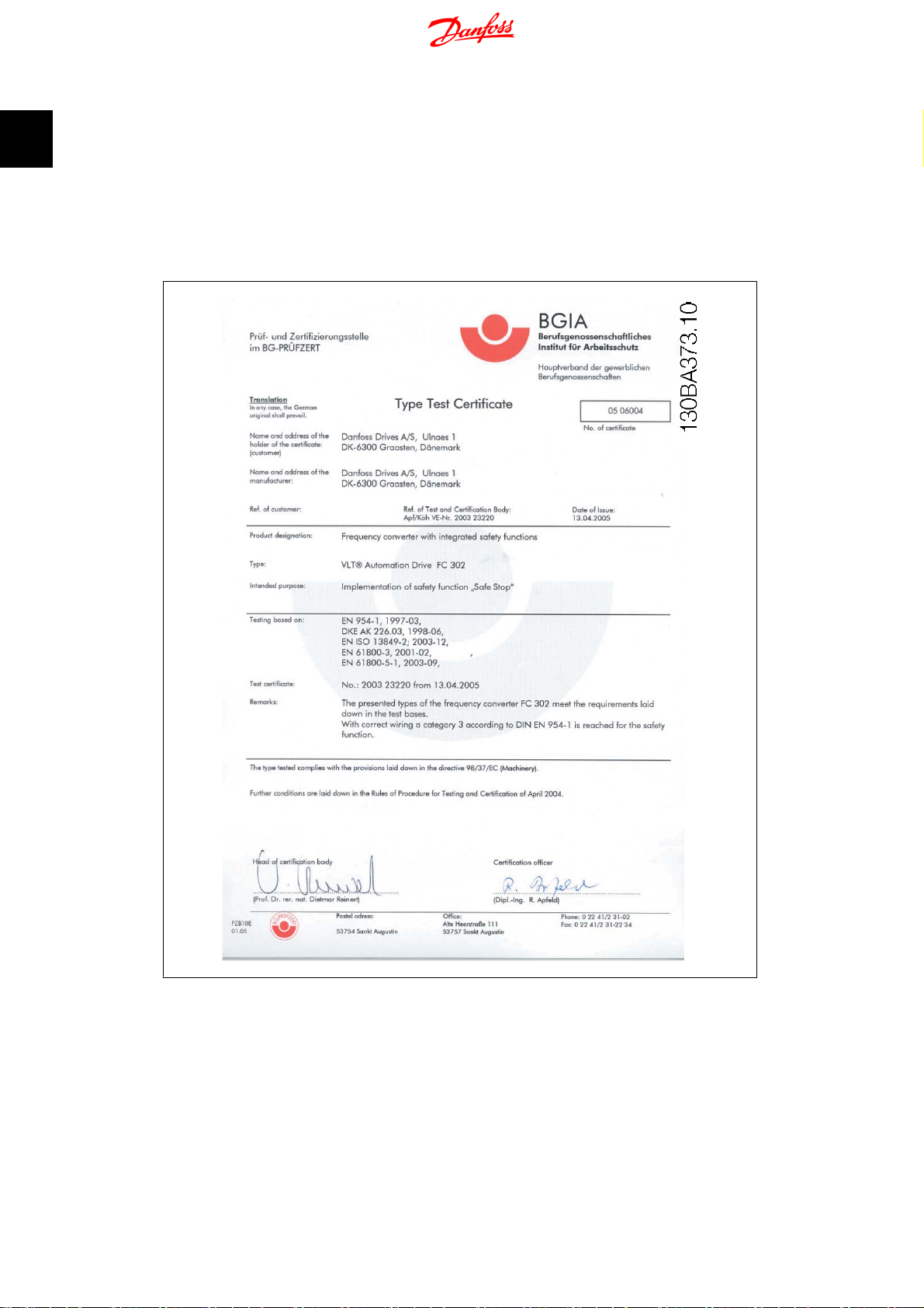
1.1.9. Safe Stop of FC 300
The FC 302, and also the FC301 in A1 enclosure, can perform the safety function
(As defined by IEC 61800-5-2) or
Off
Stop Category 0
Safe Torque
(as defined in EN 60204-1).
FC 301 A1 enclosure: When Safe Stop is included in the drive, position 18 of Type Code must be
either T or U. If position 18 is B or X, Safe Stop Terminal 37 is not included!
Example:
Type Code for FC 301 A1 with Safe Stop: FC-301PK75T4Z20H4TGCXXXSXXXXA0BXCXXXXD0
MG.33.Q1.02 - VLT
®
is a registered Danfoss trademark
7
1
1. Safety Regulation
It is designed and approved suitable for the requirements of Safety Category 3 in EN 954-1. This
functionality is called Safe Stop. Prior to integration and use of Safe Stop in an installation, a
thorough risk analysis on the installation must be carried out in order to determine whether the
Safe Stop functionality and safety category are appropriate and sufficient. In order to install and
use the Safe Stop function in accordance with the requirements of Safety Category 3 in EN 954-1,
the related information and instructions of the FC 300 Design Guide MG.33.BX.YY must be followed! The information and instructions of the Operating Instructions are not sufficient for a
correct and safe use of the Safe Stop functionality!
Syncronising Controller MCO 350 Operating
Instructions
8
MG.33.Q1.02 - VLT
®
is a registered Danfoss trademark
Syncronising Controller MCO 350 Operating
Instructions
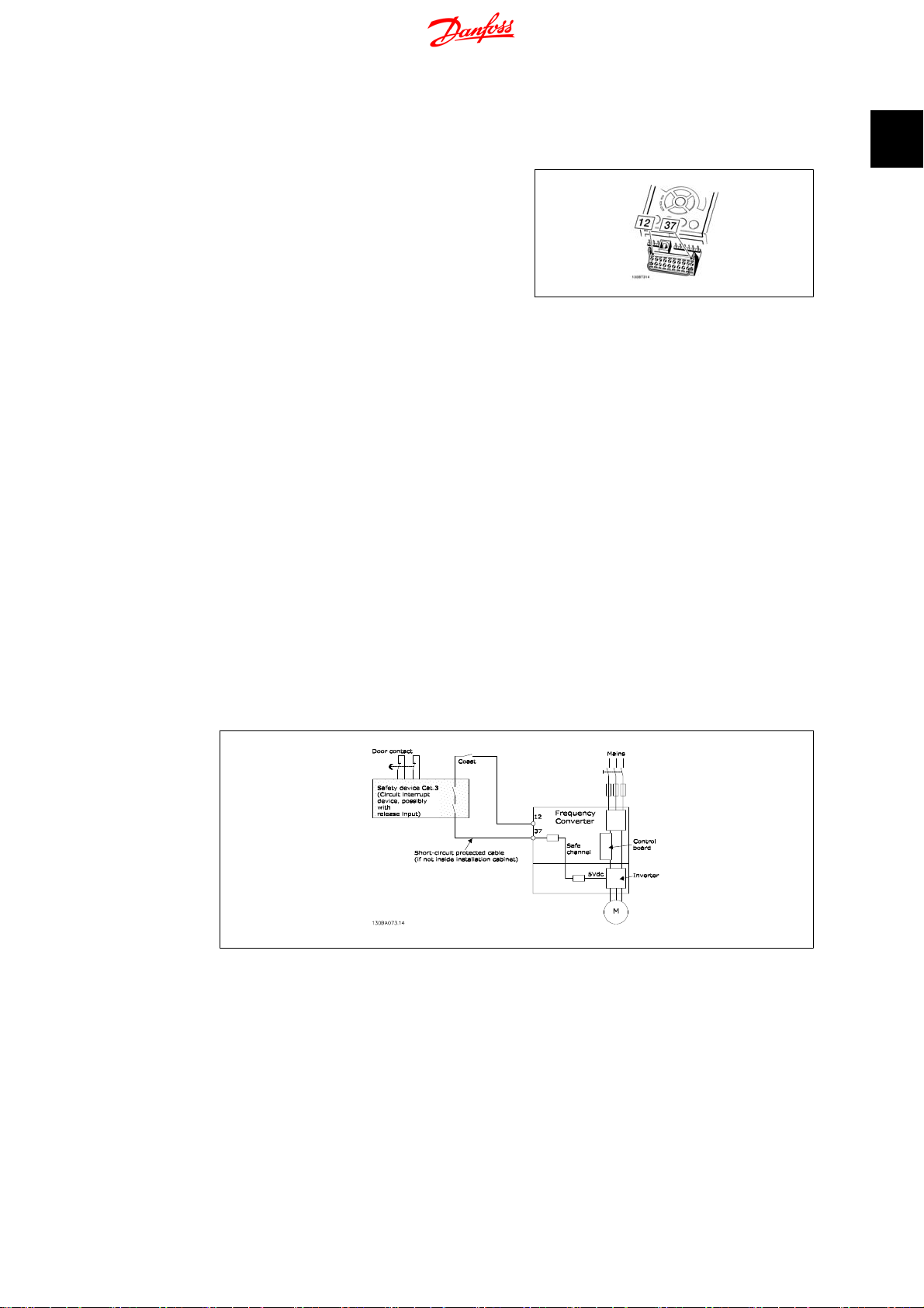
1.1.10. Safe Stop Installation (FC 302 and FC 301 - A1 enclosure only)
To carry out an installation of a Category 0 Stop (EN60204) in conformance
with Safety Category 3 (EN954-1), follow these instructions:
1. The bridge (jumper) between Terminal 37 and 24 V DC must be removed. Cutting or breaking the
jumper is not sufficient. Remove it
entirely to avoid short-circuiting. See
jumper on illustration.
2. Connect terminal 37 to 24 V DC by a
short-circuit protected cable. The 24
V DC voltage supply must be interruptible by an EN954-1 Category 3
circuit interrupt device. If the interrupt device and the frequency converter are placed in the same installation panel, you can use a regular
cable instead of a protected one.
3. Unless the FC302 itself has protection class IP54 and higher, it must be
placed in an IP 54 enclosure. Consequently, FC301 A1 must always be
placed in an IP 54 enclosure.
1. Safety Regulation
1
Illustration 1.1: Bridge jumper between terminal
37 and 24 VDC
The illustration below shows a Stopping Category 0 (EN 60204-1) with safety Category 3 (EN
954-1). The circuit interrupt is caused by an opening door contact. The illustration also shows how
to connect a non-safety related hardware coast.
Illustration 1.2: Illustration of the essential aspects of an installation to achieve a Stopping Category 0 (EN
60204-1) with safety Category 3 (EN 954-1).
1.1.11. IT Mains
Par. 14-50
the RFI filter to ground. If this is done it will reduce the RFI performance to A2 level.
RFI 1
can on FC 102/202/302 be used to disconnect the internal RFI capacitors from
MG.33.Q1.02 - VLT
®
is a registered Danfoss trademark
9

2
2. Introduction
Syncronising Controller MCO 350 Operating
Instructions
10
MG.33.Q1.02 - VLT
®
is a registered Danfoss trademark

Syncronising Controller MCO 350 Operating
Instructions
2. Introduction
2. Introduction
The synchronising Controller is an application option for VLT Automation Drive FC 301 and 302.
The application option consists of two parts:
• synchronising controller part
• Test Run part
2.2. Function Description
2.2.1. Introduction
The synchronising controller can be used in any application where a drive is to operate synchronously with a master drive. The synchronising controller acts as an electronic shaft. The gear ratio
is freely selectable and can also be changed during operation. The speed or the position is automatically and accurately controlled based on encoder feedback signals from both the master drive
and the slave drives.
For synchronous operation of two or more drives you can use:
• Speed synchronisation
• Position synchronisation or
• Marker synchronisation
2.2.2. Speed Synchronisation
2
This is the simplest type of synchronisation. It can be used to compensate for speed differences,
where it is not necessary to compensate for position errors.
The speed synchronisation between master and slave is done at maximum acceleration. To obtain
optimum control the slave drive should therefore be set for a quicker acceleration speed than that
of the master drive.
2.2.3. Position Synchronisation (angle synchronisation)
This is the electronic shaft ensuring a constant angle position ratio between master and slave
drives. In case of a position deviation the slave drive is automatically accelerated to a speed level
that is sufficient for regaining its position to the master drive (I-control like).
2.2.4. Marker Synchronisation
Marker synchronisation is an extended position control. Apart from ensuring a constant angle
position between master and slave drives, marker synchronisation provides the option of using
either an additional sensor or the zero track of the incremental encoder to compensate for any
deviations between master and slave that may occur during operation. Using marker synchronisation the slave is position synchronised until the markers is reached and then the control
compensates for the position difference between master marker and slave marker. This type of
control is used where precision cannot be achieved by using a motor mounted encoder. That could
be because of gearbox slack or other disturbance like belt elongation etc. that are not directly
measurable. Similarly, with marker synchronisation, the slave drive does not need to be brought
into the start position of the master drive at initial start-up, as this is affected automatically by
marker correction.
MG.33.Q1.02 - VLT
®
is a registered Danfoss trademark
11
2
Syncronising Controller MCO 350 Operating
2. Introduction
2.2.5. Mechanical Brake Control
The synchronising controller has a 24 V DC digital output (Output 4) and a relay output (Relay 1)
to control an electromechanical brake; this is very useful in applications when a motor (shaft)
must be kept in the same position for a longer time. This is usually the case in hoisting applications.
The brake output will be active (low) in case of an error and when synchronisation is stopped,
that means whenever motor control is switched off. The brake signal can be delayed when switched on and off in two individual parameters (par. 19-21
). Please note that the brake output is kept low in VLT mode (when input 8 is high). That
Delay
means the brake must be opened for example by means of the VLT mechanical brake function in
set-up 2.
Brake on Delay
and par. 19-22
2.3. Tips and Tricks for Synchronisation Tasks
2.3.1. Introduction
When configuring the drives to be synchronised please keep in mind that the ratios should be of
integer size. When using gear it is also important to know the number of teeth of the various gear
stages (ask the gear manufacturer) as gears are normally set up with infinite gear ratios. When
calculating the ratios between master and slave you must either use the figure PI for both of them
or not use PI at all.
Instructions
Brake off
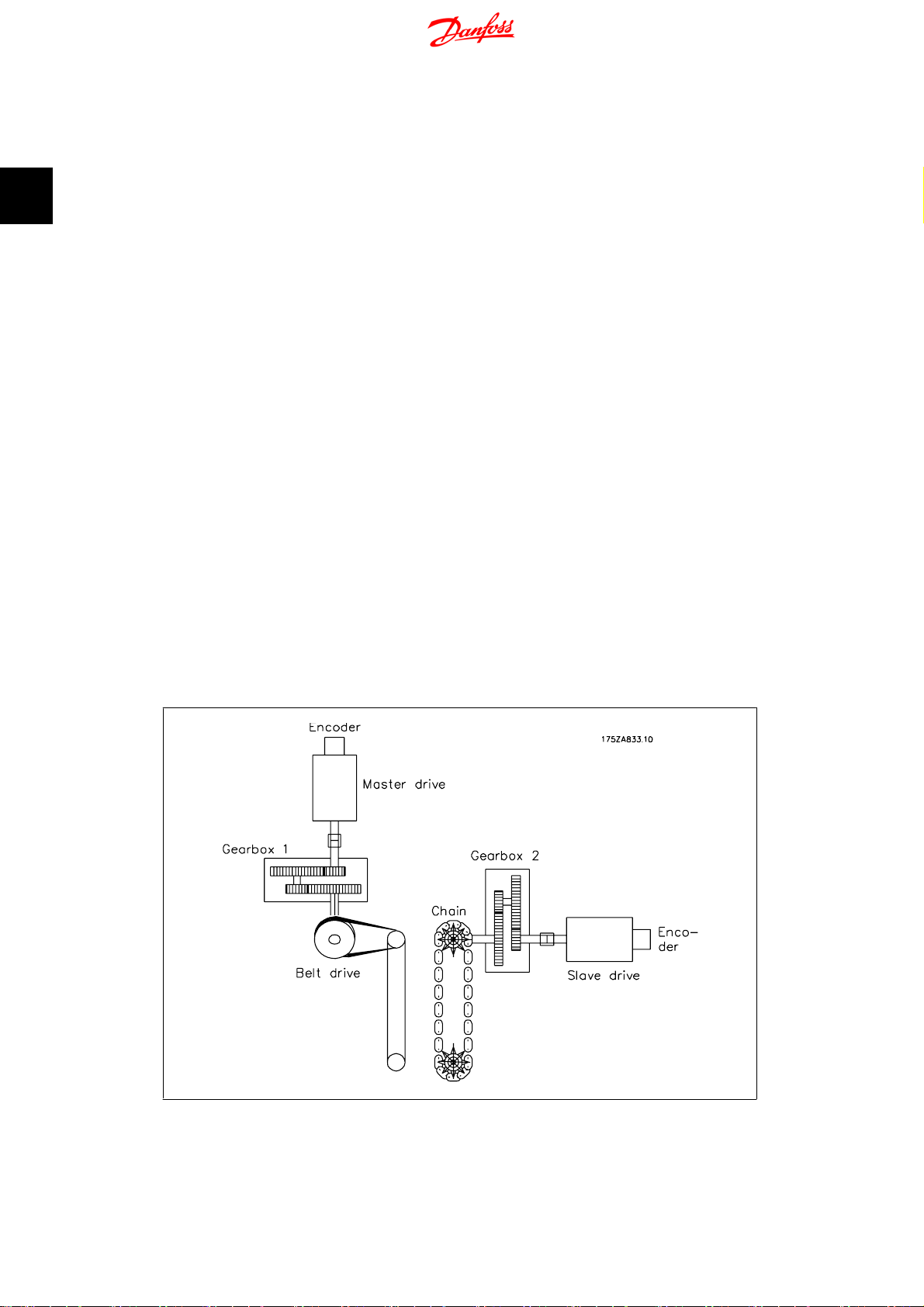
2.3.2. Example
A master drive with a 4-pole motor and an incremental encoder of 1024 increments/revolution
works on a 2-stage gear. i is specified to be 30.33. At the gear output, a belt ratio of 40:20 is
placed, driving a conveyor belt on the drive side with a diameter of 102mm. Via a 3-stage gear (i
is specified to be 46,54) the slave drive is connected to an 8-toothed chain conveyor with a tooth
pitch of 200mm.
Illustration 2.1: Calculation Example
12
MG.33.Q1.02 - VLT
®
is a registered Danfoss trademark

Syncronising Controller MCO 350 Operating
Instructions
2.3.3. Calculation with Insufficient Numerical Values
The master/slave gear ratio (numerator to denominator) is now calculated as follows:
2. Introduction
Master side = increments * i1 * i2 * power take off =
1024
incr x
Slave side = increments * i1 * power take off
=
This gives a ratio of:
That gives a numerical value of 48,460995 for the numerator and 29,7856 for the denominator.
Note: It is only possible to enter integer values. The most serious error: The master expression
contains the value Pi, an infinite number sequence. Even with small numerical values for master
and slave, the effect would always be that the drives drifted apart, as the Numerator: Denominator
expression can never be an integer.
Another error arises from the gear ratios given, as the master drive was specified with a value of
i = 30.33. The correct ratio is easily found by recalculating the individual numbers of teeth. The
gear is a 2-stage gear; the first stage is formed from two pinions, 126 to 27, and the second stage
from two pinions, 117 to 18.
The ratio is calculated as:
30.33
20
x
x
40
48, 460995
29, 7856
126x117
27
102
x
mm x
18
1
π
=30,33
= 48, 460995
1024
incr x
46.54
x
1
x
200
8
mm
2
= 29, 7856
The specified value of 30.33 thus deviates by 0.1 ‰.
This may appear small; if this error is related to the encoder resolution, however, it will be seen
that even this error is serious.
From the example it can be seen that it is important to maintain the exact values of the gear
stages and to ensure that the data include Pi either for both drives or for none of them.
2.3.4. Example with Corrected Numerical Values
Master side: Gear 1st stage 126/27 2nd stage 117/18; belt ratio 40/20; drive shaft 100 mm
Slave side: Gear 1st stage 97/10, 2nd stage 43/11, 3rd stage 27/22; effective diameter of the
sprocket wheel 510mm
1024
Master side:
Slave side:
To remove Pi from the equations, substitute both equations into the combined formula:
1024
10
Masterside
Slaveside
Incr x
x
27
Incr x97x
x
11x22x510xπ
1024
=
126x117x20
18x40x102xπ
43x27
27
Incr x
x
126x117x20
18x40x102xπ
1024
÷
10
x
Incr x
11x22x510xπ
97x43x27
MG.33.Q1.02 - VLT
®
is a registered Danfoss trademark
13

2. Introduction
1024
27
Incr x
x
18x40x1024
126x117x20x510xπx10x11x22
Incr x97x
43x27x102
Syncronising Controller MCO 350 Operating
Instructions
x
π
2
Reduce by Pi and 1024 incr.:
Reduce further:
7x5x54x11x22x117
x
97x43x27
27
This gives a ratio of
This is an absolute value, as it contains no infinite number sequences and no rounded values.
4954950
3040659
126x117x20x510x10x11x22
x
18x40x97x43x27x102
27
2.4. Hardware
2.4.1. VLT Control Card Terminals
The terminals on the control card are allocated for synchronising controller functions the following
parameter settings should therefore not be changed in synchronising mode (set-up 1):
Digital inputs 18, 19, 27, 32 and 33
Parameters 510–515 are set to
control card but they are used as inputs for the synchronising controller.
No operation
(default setting), then the inputs are ignored by the
Analogue inputs 53, 54
Parameters 315, 316 and 317 are set to
card but they are used as inputs to the synchronising controller.
Digital/analogue outputs 42
Parameters 650 are set to:
MCO 0 … 20 mA [52] analogue output
2.5. Technical Data
2.5.1. Introduction
Technical data on the control card terminals can be found in the VLT Automation Drive FC 300
Design Guide.
2.5.2. Option Card Terminals
There are two encoder interfaces, which coveers the following functions:
• Feedback encoder input
• Master encoder input / virtual master output
No function
, then the inputs are ignored by the control
14
MG.33.Q1.02 - VLT
®
is a registered Danfoss trademark

Syncronising Controller MCO 350 Operating
Instructions
2. Introduction
Terminal X55
Terminal Number Descriptive Name
Encoder 2 (Feedback)
1 + 24 V Supply
2 + 8 V Supply
3+ 5 V Supply
4 GND
5A
6 A not
7B
8 B not
9Z / Clock
10 Z / Clock not
11 Data
12 Data not
There are 2 digital input/output terminal blocks, 10 inputs and 8 outputs. (See figure below)
Terminal X57
Terminal Number Descriptive Name
Digital Inputs
1Digital Input
2 Digital Input
3Digital Input
4 Digital Input
5Digital Input
6 Digital Input
7Digital Input
8 Digital Input
9Digital Input
10 Digital Input
Terminal Number Descriptive Name
1 + 24 V Supply
2 NC
3+ 5 V Supply
4 GND
5A
6 A not
7B
8 B not
9Z / Clock
10 Z / Clock not
11 Data
12 Data not
Terminal Number Descriptive Name
1Digital Output
2 Digital Output
3Digital Output
4 Digital Output
5Digital Output
6 Digital Output
7Digital Output
8 Digital Output
Terminal X56
Encoder (Master)
Terminal X59
Digital Output
2
Terminal X58
Terminal Number Descriptive Name
24 V Supply
1 + 24 V Supply
2 GND
There are 2 digital input/output terminal blocks, 10 inputs and 8 outputs. (See figure below)
MG.33.Q1.02 - VLT
®
is a registered Danfoss trademark
15
2
2. Introduction
Syncronising Controller MCO 350 Operating
Instructions
2.5.3. Encoder Monitor
Both encoder interfaces are equipped with a monitoring circuit that can detect open circuit as well
as short circuit of each encoder channel. Each encoder channel has a LED showing the status:
Green light means OK, no light means fault. An encoder fault will result in an ”Option error” 192
if encoder monitoring is activated via parameter 3239 (master) and 3209 (slave).
2.5.4. Option Card Layout
MCO 350 control terminals are plug connectors with screw terminals; the terminal blocks are
duplicated to enable use of the same MCO 350 in all frame sizes. See illustration to locate the
terminal blocks:
16
MG.33.Q1.02 - VLT
®
is a registered Danfoss trademark

Syncronising Controller MCO 350 Operating
Instructions
(1) is used with frame sizes A2 and A
(2) is used with frame sizes A5, B1 and B2
X55 = Encoder 2
X56 = Encoder 1
X57 = Digital inputs
X58 = 24VDC supply
X59 = Digital outputs
2.5.5. General Technical Data
− All inputs, outputs and supply voltages are protected against short circuit.
− All inputs, outputs and supply voltages are galvanic isolated from high voltages such as mains
supply and motor voltage (PELV).
− Encoder signals are monitored during operation and standstill.
− All MCO 350 parameters including user defined application parameters are accessible via the
FC 300 Local Control Panel.
− MCO 350 can be combined with other FC 300 options, namely PROFIBUS and DeviceNet interface.
− All digital inputs and outputs are galvanic isolated from the internal electronics and can be
sourced from an external 24V power supply.
2. Introduction
2
Connection Terminals:
Maximum cross section, rigid wire 1.5 mm2/AWG 16
Maximum cross section, flexible wire 1.5 mm2/AWG 16
Maximum cross section, wire with enclosed core 1.5 mm2/AWG 16
Minimum cross section 0.082/AWG 28
Digital inputs:
Number of programmable digital inputs 10
Terminal block X57
Terminal number 11),21),3,4,5,6,7,8,9,10
Logic PNP or NPN
Voltage level 0 - 24 V DC
Voltage level 0 - 24 V DC
Voltage level, logic '0' PNP < 5 DC
Voltage level, logic'1' PNP > 10 V DC
Voltage level, logic '0' NPN
Voltage level, logic '1' NPN
Maximum voltage on input 28 V DC
2)
2)
> 19 V DC
< 14 V DC
1) ) Selected in parameter 5-00 Digital I/O mode.
The digital inputs are galvanic isolated from the internal electronics and can be sourced by an
external 24V power supply.
Digital outputs:
Number of programmable digital outputs 8 (6)
Terminal block X59
Terminal number 11), 21),3,4,5,6,7,8
Driver type push/pull
Logic PNP or NPN
Voltage level 0 - 24 V DC
Max. output current (sink or source) with internal power supply (total Σ) 40 mA
Max. output current (sink or source) with external power supply (per output) 100 mA
Terminals X59-1 and X59-2 can be programmed as input, parameter 33-60.
1)
1
2)
MG.33.Q1.02 - VLT
®
is a registered Danfoss trademark
17

2. Introduction
Syncronising Controller MCO 350 Operating
Instructions
2
Combined Digital Inputs/Outputs:
Number of digital outputs which can be used as digital inputs 2
Terminal block X59
Terminal number 1,2
Logic PNP or NPN
Voltage level 0 - 24 V DC
Voltage level 0 - 24 V DC
Voltage level, logic '0' PNP < 10 V DC
Voltage level, logic'1' PNP > 17 V DC
Voltage level, logic '0' NPN > 13 V DC
Voltage level, logic '1' NPN < 6 V DC
Maximum voltage on input 28 V DC
1) Terminals X59-1 and X59-2 can be programmed as input, parameter 33-60.
2) Selected in parameter 5-00 Digital I/O mode.
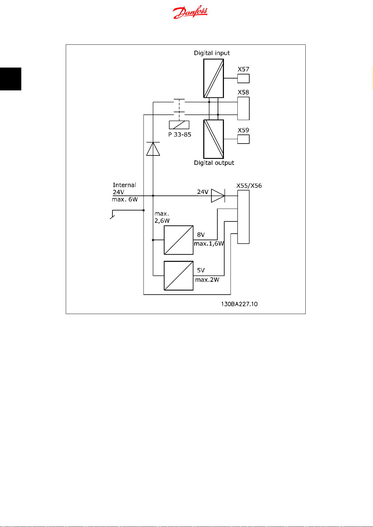
24 V DC Supply Output
Terminal block X58
Terminal number 1,2
Maximum load 65 mA
The internal 24V power supply can be disconnected via parameter 33-85, an external 24V power
supply must then be connected to X58-1 and X58-2.
Encoder Inputs
Number of encoder inputs 2
Terminal block X55 and X56
Terminal number 5,6,7,8,9,10,11,12
Input impedance 120Ω
Maximum voltage on inputs 5 V DC
Cable type Screened cable with a twisted pair of wires for each encoder channel
Incremental encoder type RS422/TTL
Maximum frequency 410 kHz
Phase displacement between A and B 90°±30°
Maximum cable length 300 m
Absolute encoder type SSI
Data coding Gray
Data length 12 - 37 bit
Clock frequency 78 kHz - 2 MHz
Absolute encoder type SSI
Maximum cable length 150 m
1) Always observe specifications/limitations prescribed by the encoder supplier.
2) 150 m cable is possible up to 500 kHz clock frequency, above 500 kHz cable length must be
limited further.
1)
2)
1)
1)
1)
1)
Encoder Output
Number of encoder outputs 1
Terminal block X56
Terminal number 5,6,7,8,9,10,11,12
Signal type RS 422Ω
Maximum frequency 410 kHz
Maximum number of slaves 31 (more with repeater)
Maximum cable length 400 m
Encoder Output
Number of supply voltages 3
Terminal block X55 and X56
Terminal number 1,2,3,4
18
MG.33.Q1.02 - VLT
®
is a registered Danfoss trademark
Syncronising Controller MCO 350 Operating
Instructions
2. Introduction
24 V, max load 250 mA
8 V, max load 250 mA
5 V, max load 400 mA
Absolute encoder type SSI
Maximum cable length 150 m
1) This is maximum load when only one supply voltage is used; when 2 or 3 supply voltages are
used simultaneously the load must be reduced accordingly. The following must be observed:
load24V + load8V + load5V ≤ 6W and load8V + load5V ≤ 2W.
2) 8 V is only available at terminal block X55.
2.6. Example of Encoder Interface connections
1) 2)
1)
1)
1)
2
MG.33.Q1.02 - VLT
®
is a registered Danfoss trademark
19

2
2. Introduction
2.7. Description of Terminals
I/O Number Designation Description
12 24 V DC 24V power supply for switches etc.
13 24 V DC 24V power supply for switches etc.
18 Disable Resync The Resync function (to be enabled by param
19 Home run Starts the homing.
20 GND Ground for 24 V.
27 Reset/Enable Error reset on rising edge. To enable opera-
32 Test run reverse Test run; Program 1:
Speed/Pos - Synchronous operation; Program 2:
Syncronising Controller MCO 350 Operating
Instructions
1924) can be temporarily disabled by setting
this input to 1
tion, this input must be switched to “1”. “0” =
motor coast.
Test run reverse at the speed defined in Parameter 19-01
In velocity synchronous mode (P. 1901 = 0, 3,
6 or 7) the gear ratio and thus the velocity of
the slave can be changed by the value specified in parameter 1912.
In position synchronous and marker synchronous operation (P. 1901 = 1, 2, 4 or 5), the
position offset of the slave can be changed by
the value specified in Parameter 1912. The
sign of the value in parameter 1912 selects the
offset type to be absolute or relative.
Absolute offset means that the fixed offset of
parameter 1912 is changed and this offset is
executed when restarting synchronisation.
Relative offset means that the actual slave position is displaced but the fixed offset of parameter 1912 is unchanged. This again means
that the actual slave position is maintained
when restarting synchronisation. Relative offset is useful when always changing the offset
in the same direction as this would give a very
high fixed offset when using absolute offset.
This high fixed offset would then be executed
when restarting synchronisation and the min.
or max. limit of parameter 1912 would eventually be reached.
20
MG.33.Q1.02 - VLT
®
is a registered Danfoss trademark

Syncronising Controller MCO 350 Operating
Instructions
I/O Number Designation Description
33 Test run forward Test run; Program 1:
Speed/Pos + Synchronous operation; Program 2:
01 COM; 240V AC/2A Relay output 1:
02 Electromechanical
brake: NO
03 NC
04 COM; 50V AC/1A; 75V
DC/1A
05 NO
06 NC
39 GND Ground for analogue inputs/outputs.
42 Slave/Master velocity The output value is scaled to maximum slave
50 10V DC 15mA Power supply for reference value potentiome-
53 0 - 10V In Serves as reference input for the virtual mas-
54 0 - 10V In Serves as numerator for the gear ratio if “6” or
2. Introduction
Test run forward at the speed defined in Parameter 1901
2
In velocity synchronous mode (P. 1901 = 0, 3,
6 or 7) the gear ratio and thus the velocity of
the slave can be changed by the value specified in parameter 19-12.
In position synchronous and marker synchronous operation (par. 19-01 = 1, 2, 4 or 5), the
position offset of the slave can be changed by
the value specified in Parameter 1912. The
sign of the value in parameter 1912 selects the
offset type to be absolute or relative.
Absolute offset means that the fixed offset of
parameter 19-12 is changed and this offset is
executed when restarting synchronisation.
Relative offset means that the actual slave position is displaced but the fixed offset of parameter 19-12 is unchanged. This again
means that the actual slave position is maintained when restarting synchronisation. Relative offset is useful when always changing the
offset in the same direction as this would give
a very high fixed offset when using absolute
offset. This high fixed offset would then be
executed when restarting synchronisation and
the min. or max. limit of parameter 1912
would eventually be reached.
Relay 1 is open (brake activated) during power
off, and start-up of the frequency converter.
Afterwards the brake-control depends on the
selected Sync mode.
Relay output 2:
Function can be configured by means of Parameter 540.
velocity (parameter 32-80);
The output can be selected between slave or
master velocity by means of parameter 19-25
ter
ter if “0“ is selected in Parameter 19-16.
“7” is selected in parameter 19-01.
MG.33.Q1.02 - VLT
®
is a registered Danfoss trademark
21

2
2. Introduction
2.7.1. Standard RS 485-Interface
I/O Number Designation Description
61 Ground RS 485 Not used
68 RS 485-P Not used
69 RS 485-N Not used
2.7.2. MCO 350 Terminal X57
I/O Number Designation Description
1 I1 - Sync-Start Start and stop of synchronisation. Input
2 I2 - Take over gear ratio Activates the gear ratio selected at Ter-
3 I3 - Start/Stop virtual master Test run; Program 1: Start test run
4 I4 - Hold The drive is held at a programmable
5 I5 - Master marker input When using external marker signal for
6 I6 - Slave marker input When using external marker signal for
7 I7 - Measuring of the master marker
interval
Home switch Synchronous operation; Program
8 I8 - measuring of the slave marker
interval
I8 - VLT mode selection Synchronous operation; Program
9
10
Gear ratio 2
Gear ratio 2
0
1
Syncronising Controller MCO 350 Operating
Instructions
1 must be toggled if synchronisation
was interrupted by an error or by input
27 (motor coast). Behaviour at stop can
be selected via parameter 1901.
minals 9 and 10.
with virtual master. Synchronous op-
eration; Program 2: The virtual master is accelerated up to the set pulse
frequency, or stopped, with the set
ramp time.
(parameter 1903) speed, or the current
speed (parameter 1902 = 1). Synchronous control is not activated.
the master drive it must be connected
to this input.
the slave drive it must be connected to
this input.
Test run; Program 1:
Measuring of the master marker interval
is started.
2:
If a home position is to be attained, the
home switch must be connected here.
The signal must show a rising edge
Test run; Program 1:
Measurement of the slave marker interval is started.
2:
Switches the VLT to normal frequency
converter operation. The settings for
this operating mode are to be made in
Parameter set-up 2. Refer to the VLT
Automation Drive Product Manual.
Gear ratio least significant bit
Gear ratio most significant bit
22
MG.33.Q1.02 - VLT
®
is a registered Danfoss trademark
Syncronising Controller MCO 350 Operating
Instructions
2.7.3. MCO 350 Terminal X59
I/O Number Designation Description
1 O1 - READY Ready, i.e. for the number of marker signals that were
2 O2 - FAULT Fault, i.e. for the number of marker signals that were
3 O3 - ACCURACY The drive runs within the tolerance specified in Param-
4 O4 - Brake control This output can be used to control a mechanical brake.
5 O5 - Saving This output stays high while saving is in progress. The
6 O6 - Drive running Signal “1” when the drive is running.
7 O7 - Home reached If the data value “1” was chosen in Parameter 3300, this
8 O8 - Ready, no error The synchronising controller is ready for operation.
2. Introduction
specified in Parameter 3325, the slave drive has run
within the tolerance (Accuracy).
specified in Parameter 3324, the slave drive has run outside the tolerance (Accuracy). OR when the number of
marker signals have been missing when marker monitor
is activated in parameter 1923.
eter 3313.
“0” means that the brake must be closed (braking) “1”
means that the brake must be open (not braking)
saving is initiated by Parameter 1900, Input 4 or fieldbus
bit 4.
output shows “1” when homing is completed.
2
2.8. Description of Fieldbus Interface
NB!
This section is only relevant if the VLT is equipped with a Field bus interface (option)
as well as the synchronising controller.
The synchronising controller can be controlled via the digital/analogue inputs or via field bus. The
control source can be selected individually for test-run and synchronising in the parameters 1919
(test-run) and 1920 (synchronising). There can only be one control source at a time meaning that
the digital/analogue inputs are inactive when Field bus is selected as control source and visa versa.
The only exception is input 27, which is always stop/enable also when Field bus is selected as
control source. In synchronising mode three signals are only available as digital inputs even when
Field bus is selected as control source that is the marker signals for marker synchronisation and
the Home switch. This is because these signals are too time-critical for Field bus control. Status
signals are always available on the digital/analogue outputs but they are only available via Field
bus when Field bus is selected as control source.
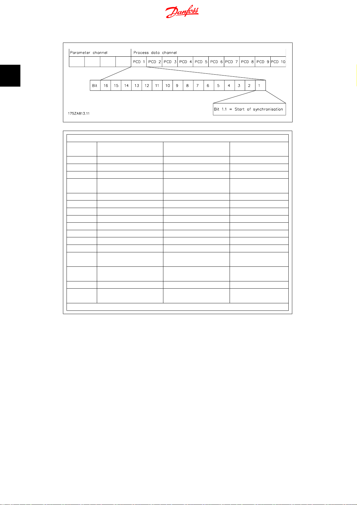
2.8.1. Data Layout
Control and status signals are transferred via the so-called process data channel (PCD) of the
various fieldbus interfaces. The telegram structure and the available number of data words depends on the Fieldbus used, please refer to the manual of the Fieldbus option in use for further
details. The below example is based on the layout of a PROFIBUS telegram, the so-called PPO:
Example using PROFIBUS PPO type 5:
MG.33.Q1.02 - VLT
®
is a registered Danfoss trademark
23
2
2. Introduction
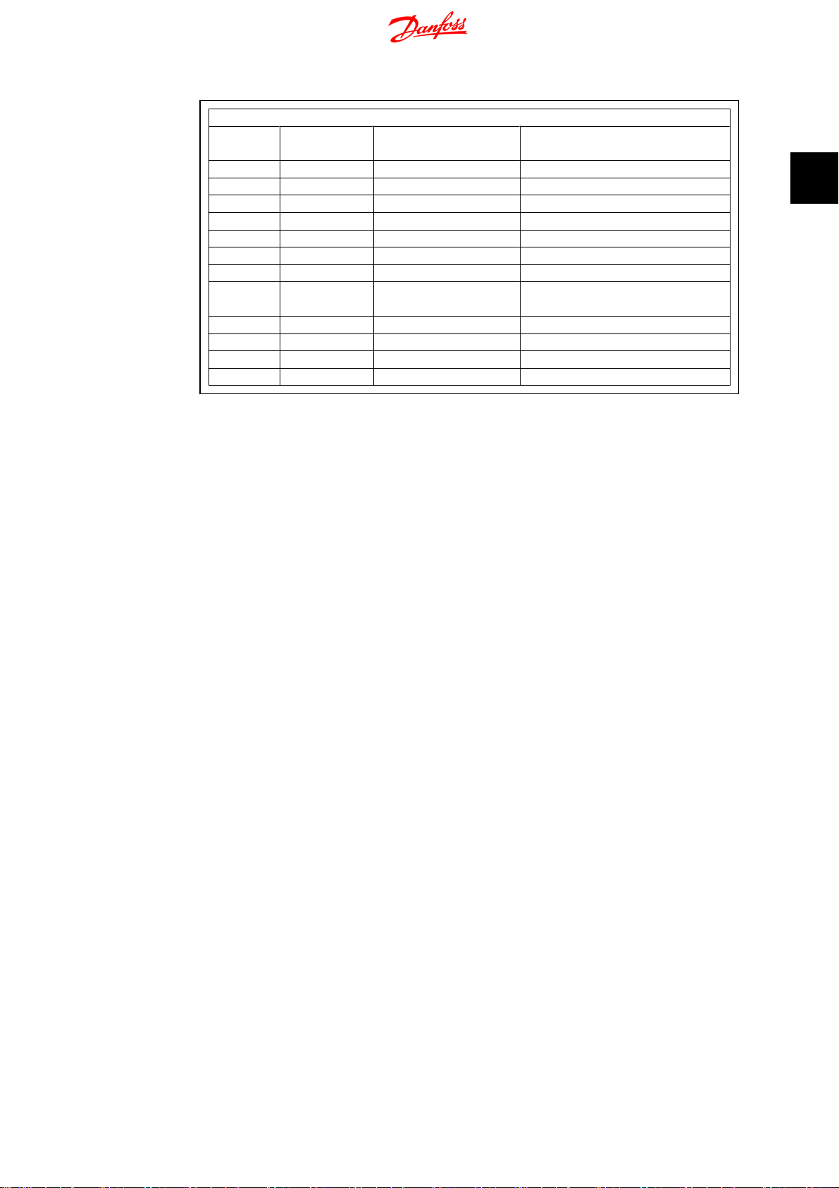
Fieldbus Control Signals
Fieldbus
[word.bit]
1.1 Not used Start of synchronisation 1
1.2 Not used Take over gear ratio 2
1.3 Start/stop virtual master Start/stop virtual master 3
1.4 Not used Save gear-settings (only
1.5 Not used VLT-mode 8
1.6 Not used Gear-ratio select LSB 9
1.7 Not used Gear-ratio select MSB 10
1.8 Not used Start homing 19
1.9 Reset/enable Reset/enable 27
1.10 Not used Hold 29
1.11 Not used Speed/position - 32
1.12 Not used Speed/position + 33
1.13 Measuring master marker
1.14 Measuring slave marker
1.15 Test-run left Not used 32
1.16 Test-run right Virtual master negative di-
2 Virtual master reference* Virtual master reference* 53
Syncronising Controller MCO 350 Operating
Instructions
Test Run synchronising Corresponding Input
4
possible when stopped!)
Not used 7
distance
Not used 8
distance
33
rection
*) Only when par. 19-16 = 2.
24
MG.33.Q1.02 - VLT
®
is a registered Danfoss trademark
Syncronising Controller MCO 350 Operating
Instructions
Fieldbus Status Signals
Fieldbus
[word.bit]
1.1 Not used Ready 1
1.2 Not used Fault 2
1.3 Not used Accuracy 3
1.5 Saving Saving 5
1.6 Running Running 6
1.7 Not used Home reached 7
1.8 Ready, no error Ready, no error 8
2 Track error Track error Par. 19-93 (testrun)/
3 Not used synchronising error Par. 19-93
4 Not used Status of synchronisation Par. 34-60
5 Slave speed Slave speed Par. 19-94
6 Master speed Master speed Par. 19-95
Test Run synchronising Corresponding Output/Parame-
2. Introduction
ter
2
Par. 19-96 (synchronising)
MG.33.Q1.02 - VLT
®
is a registered Danfoss trademark
25

3
3. Programming
Syncronising Controller MCO 350 Operating
Instructions
26
MG.33.Q1.02 - VLT
®
is a registered Danfoss trademark

Syncronising Controller MCO 350 Operating
Instructions
3. Programming
3.1. Description of Parameters
3. Programming
19-00 Store data
Option: Function:
Here you can save the gear-ratio data permanently in the EEPROM
[0] no function
[1] Gear data is being
saved
19-01 Test run; Program 1
Option: Function:
19-01 Synchronous operation; Program 2
Option: Function:
While saving, the value remains “1“; when saving is finished,
the value automatically reverts to “0“. At the same time, during
saving, Output O5 “Saving“ is set to “1“. Saving is not possible
during operation, but only in the stopped state.
Test run speed: Specify here the speed at which the test runs
are to be carried out. The speed is specified as a percentage of
the maximum speed defined in par. 32-80.
Type of operation: Select here the type of operation of the synchronising Controller
3
[0] Speed synchronising
[1] Position synchronising
[2] Marker synchronising
[3] Speed synchronising with motor coast after stop
[4] Position synchronising with motor coast after stop
[5] Marker synchronising with motor coast after stop
[6] . Speed synchronising with motor coast after stop and setting of
gear ratio via analogue input 54
[7] Speed synchronising with setting of gear ratio via analogue in-
put 54.
With the selections “0” - “2” and “7” the motor is always controlled keeping the actual position
when stopping synchronisation (input 1 = “0”).
MG.33.Q1.02 - VLT
®
is a registered Danfoss trademark
27

3
3. Programming
19-02 Test run; Program 1
Option: Function:
[0] If “0“ is set, the slave drive is brought to the speed set in par.
[1] If “1“ is set, the actual speed is maintained. While these signals
Syncronising Controller MCO 350 Operating
Instructions
Test run acceleration: Specify here the acceleration for the
test run as a percentage of the maximum acceleration. 100 %
means that the drive accelerates with the minimum ramp specified in par. 32- 8 1 . 5 0 % m e a ns that the drive only proceeds with
half the acceleration, i.e. the acceleration takes twice as long as
with the minimum ramp specified in par. 32-81.
Synchronous operation; Program 2: Hold function:
If the contact at Terminal 29 is closed, the slave drive is disengaged, i.e. it no longer runs in synchrony with the master.
19-03.
are present, the current Hold speed can be changed by means
of Inputs 32 and 33.
19-03 Test run; Program 1
Option: Function:
Test run distance: Specify the distance for the test run in quad
counts.
Synchronous operation; Program 2:
Hold speed: If Hold function “0“ was selected, enter here the
speed as a percentage of the maximum speed (par. 32-80).
19-04 Test run, program 1: synchronising type (Sync type)
Option: Function:
This parameter is used to specify the type of synchronisation
used when optimising the PID controller for synchronisation by
means of the virtual master.
[0] Speed synchronising Select “0” if speed synchronising should be used in synchronous
mode
[1] Position synchronis-
ing
Select “1” if position or marker synchronising should be used in
synchronous mode.
Synchronous operation; Program 2:
Delta hold speed: Specify the percentage by which the hold
speed is to change when Input 32 or 33 is activated during Hold
mode.
19-05 Test run, program 1: Activate feed forward and PID calculation (FFVEL calc.)
Option: Function:
This parameter is used to trigger automatic calculation of the
optimal value for velocity feed forward (par. 32-65) as well as
PID sample time (par. 32-69), proportional factor (par. 32-60)
and derivative factor (par. 32-61).
[0] No action
28
MG.33.Q1.02 - VLT
®
is a registered Danfoss trademark

Syncronising Controller MCO 350 Operating
Instructions
3. Programming
[1] Activate calculation of
velocity feed forward
(par. 3265)
[2] Activate calculation of velocity feed forward (par. 32-65), PID
The parameter value is automatically reset to
“0” when the calculation is done.
NB!
If any of the above mentioned parameters are changed the calculation must be
repeated.
The calculation is based on the following parameters that must
be set before the calculation is started:
Par. 32-00/32-02 “Slave encoder type”,
Par. 3201/3203 “Slave encoder resolution”,
Par. 32-80 “encoder velocity”
Par. 32-69 “PID sample time”.
sample time (par. 32-69), Proportional factor (par. 32-60) and
derivative factor (par. 32-61). The calculations are based on the
following parameters that must be set before the calculation is
started:
Par. 32-00/32-02 “Slave encoder type”,
Par. 32-01/32-03 “Slave encoder resolution”,
Par. 32-80 “Maximum velocity”,
3
Synchronous operation; Program 2:
Gear ratio no.: Select the number of the gear ratio that you want to edit in parameters 19-06
to 19-10.
19-06 Gear ratio numerator
Option: Function:
Enter the numerator for the gear ratio selected in par. 19-05.
Ensure that the gear ratio matches the marker ratio.
19-07 Gear ratio denominator
Option: Function:
Enter the denominator for the gear ratio selected in par. 19-05.
Ensure that the gear ratio matches the marker ratio.
19-08 Slave marker quantity
Option: Function:
Enter the number of slave markers for the marker ratio. Ensure
that the gear ratio matches the marker ratio.
MG.33.Q1.02 - VLT
NB!
This parameter is only used in marker synchronising mode (par. 19-01 = 2 or 5).
®
is a registered Danfoss trademark
29
3
3. Programming
19-09 Master marker quantity
Option: Function:
19-10 Fixed offset
Option: Function:
Syncronising Controller MCO 350 Operating
Instructions
Enter the number of master markers for the marker ratio. Ensure that the marker ratio matches the gear ratio.
NB!
This parameter is only used in marker synchronising mode (par. 1901 = 2 or 5).
Enter the position offset. This makes it possible to compensate
for differences in the placing of the encoder or markers. Input
is in quad counts.
Offset_slave
19-11 Step time
Option: Function:
Enter the time after which
• with the Hold function activated and the presence of
• in the engaged state, without Hold, the next change of
Input is in milliseconds.
19-12 Step Length
Option: Function:
Enter the step value for changing the position offset in quad
counts. Par. 19-10 is changed accordingly. The sign of this parameter selects the offset type when changing the offset via the
position + and - inputs:
A positive value selects absolute offset (see Input 32/33).
A negative value selects relative offset (see Input 32/33).
NB!
Offset is related to the master position. Offset related to the slave position can be calculated as
follows:
O ffest x Parameter
:
one of the signals at Terminal 32 or 33, a change in
speed takes place;
the slave position takes place.
Parameter
19 − 06
19 − 07
30
MG.33.Q1.02 - VLT
®
is a registered Danfoss trademark

Syncronising Controller MCO 350 Operating
Instructions
19-13 Slave speed factor
Option: Function:
19-14 Master speed factor
Option: Function:
3. Programming
Enter here the factor by which the slave speed must be scaled,
so that the desired value is displayed. The following formula
applies for calculation of the factor:
N
x
400
Factor
Example: Resolution 1024 PPR, desired display 100 at 15001/
min
Factor
Enter here the factor by which the master speed must be scaled,
so that desired value is displayed. The formula for calculation of
the factor is:
Factor
Set
=
1
1500
=
=
min
N
x
Set
x Slaveencoder_resolution
60
xDisplay_value
x
400x1024
60x100
400
x Slaveencoder_resolution
60
xDisplay_value
Incr
Rev
.
.
= 102400
3
19-15 synchronising error display factor
Option: Function:
Enter the factor by which the error must be scaled, so that the
desired value is displayed. The formula for calculation of the
factor is:
Speed synchronisation: The factor should be 100, the synchronising error is then displayed in RPM related to the slave.
Position synchronisation:
N
x
400
Factor
Example: Resolution 1024 PPR, user unit is 100 mm/revolution
Factor
19-16 Virtual master reference value
Option: Function:
Select the type of reference value for the virtual master.
[0] reference value signal 0.. *10V via Terminal 53,
Set
=
N
x
Set
=
xSlaveencoder_resolution
U ser unit
400x1024
100
= 4096
[1] reference value can be set via par. 310 subindex 1.
[2] reference value is set via Field bus (PCD 2). +/- 1000 corre-
sponds to maximum virtual master velocity (par. 1918).
MG.33.Q1.02 - VLT
®
is a registered Danfoss trademark
31

3. Programming
19-17 Virtual master acceleration
Option: Function:
Syncronising Controller MCO 350 Operating
Instructions
Enter here the acceleration for the virtual master in Hz/s.
Virtual master acceleration =
Pulsfrequenz Hz
t s
3
Example: The virtual master must correspond to an encoder
with 1024 inc/rotation. The maximum speed of 25 encoder rotations per second must be attained in 1 second.
Virtual master acceleration =
1
25
x
1024
s
19-18 Virtual master maximum speed
Option: Function:
Enter here the maximum speed of the virtual master in Hz.
Virtual master maximum speed =
Increments
.
Rev
Example: The maximum virtual master signal must correspond
to an incremental encoder with 1024 inc/rotation at a rotational
speed of 50 rotations/s.
Virtual master maximum speed =
1024
x
1
1
s
x
50
s
Incr
.
Rev
.
= 25600
Rev
.
s
= 51200 1
/
Hz
s
/
s
19-19 Control source test run (Contr. testrun)
Option: Function:
This parameter is used to select the control source in test run
mode (par. 33-80 = “1”). There can only be one control source
at a time: Digital inputs or field bus control word. Only exception
is input 27 which is always stop also with field-bus control.
When digital control is selected status signals are updated on
the digital outputs, when field bus control is selected status signals are updated on digital outputs as well as field bus.
[0] Digital Inputs “0” means that all control commands are activated via the digital
inputs according to the description of the terminals.
[1] Fieldbus “1” means that all control commands are activated via the field
bus control word according to the description of field bus control.
NB!
The new control source selected in this parameter
is not active before next power up (power cycle).
32
MG.33.Q1.02 - VLT
®
is a registered Danfoss trademark

Syncronising Controller MCO 350 Operating
Instructions
19-20 Control source synchronising (Contr. synchron)
Option: Function:
[0] Digital Inputs means that all control commands are activated via the digital
[1] Fieldbus means that all control commands are activated via the field bus
3. Programming
This parameter is used to select the control source in synchronising mode (par. 33-80 = “2”). There can only be one control
source at a time: Digital inputs or field bus control word. Only
exception is input 27 which is always stop also with field-bus
control.
When digital control is selected status signals are updated on
the digital outputs, when field bus control is selected status signals are updated on digital outputs as well as field bus.
inputs according to the description of the terminals.
control word according to the description of field bus control.
NB!
The new control source selected in this parameter
is not active before next power up (power cycle).
3
19-21 Brake on delay (Brake on delay)
Range: Function:
This parameter is used to specify the delay time between closing
the mechanical brake (output 4) and disabling motor control
(motor coast). This is necessary to avoid loosing the load because of the reaction time of the mechanical brake.
[0...5000 msec.] The value must be set according to the reaction time of the me-
chanical brake.
19-22 Brake off delay (Brake off delay)
Range: Function:
This parameter is used to specify the delay time between activating motor control and opening the mechanical brake (output
4). This is necessary to avoid loosing the load because of the
reaction time of the mechanical brake.
[0...5000 msec.] The value must be set according to the reaction time of the me-
chanical brake.
19-23 Marker monitor
Option: Function:
This parameter specifies the behaviour when markers are missing in Marker synchronising mode (par. 1901 = 2 or 5)
[0] Output 2 Fault is set when “not accuracy” for x number of markers (x =
par. 33-24).
[1] Output 2 Fault is set when “not accuracy” for x number of markers (x =
par. 33-24) OR when x number of markers are missing.
MG.33.Q1.02 - VLT
®
is a registered Danfoss trademark
33

3
3. Programming
[2] Output 2 Fault is set when “not accuracy” for x number of markers (x =
19-24 Resync.
Option: Function:
[0] Inactive
[1] Active
Syncronising Controller MCO 350 Operating
Instructions
par. 33-24) and Output 2, fault is set and the error handler is
called when x number of markers are missing.
NB!
This function can only be used if marker windows
are used (par. 33-22 and 33-21).
With resync active synchronisation will remain active while the
slave is stopped (Input 1 and/or Input 27 = 0). The actual synchronising error will be corrected with the set velocity and
acceleration when restarting synchronisation.
19-25 Select Analogue output 42
Option: Function:
[0] Slave speed
[1] Master speed
19-92 Software version number
Option: Function:
The software version of the synchronising controller is displayed
here.
19-93 Test run; Program 1
Option: Function:
Track error“: The track error is displayed in quad counts.
Synchronous operation; Program 2: “Sync-error”: The syn-
chronisation error is displayed with the value calculated in par.
19-15.
19-94 Slave speed (read only)
Option: Function:
The slave speed is displayed with the value calculated in par.
19-13.
19-95 Master speed (read only)
Option: Function:
The master speed is displayed with the value calculated in par.
19-14.
34
MG.33.Q1.02 - VLT
®
is a registered Danfoss trademark

Syncronising Controller MCO 350 Operating
Instructions
19-96 Track error (read only)
Option: Function:
32-00 Incremental Signal Type (Slave)
Option: Function:
[0] None Choose if an absolute encoder is used
[1] RS422 (TTL/Line driv-
er)
[2] Sinusoidal 1 Vpp Choose if 1 V peak to peak analog incremental encoder is used.
32-01 Incremental Resolution (Slave)
Option: Function:
3. Programming
“Track-error”: The synchronisation error is displayed with the
value calculated in par. 19-15.
3
Enter the pulses per revolution
32-02 Absolute Protocol (Slave)
Option: Function:
[0] None choose if an incremental encoder is used.
[1] SSI.
[2] SSI with filter choose if the encoder signal is unstable.
32-03 Absolute Resolution (Slave)
Option: Function:
Enter the positions per revolution.
32-05 Absolute Encoder Data Length (Slave)
Option: Function:
Enter the number of data bits of the connected absolute encoder.
32-06 Absolute Encoder Clock Frequency (Slave)
Option: Function:
Enter the clock frequency according to the encoder manufacturer specifications.
32-07 Absolute Encoder Clock Generation (Slave)
Option: Function:
Off Clock signal is not generated.
On Clock signal is generated, this is most commonly used.
MG.33.Q1.02 - VLT
®
is a registered Danfoss trademark
35

3
3. Programming
32-08 Absolute Encoder Cable Length (Slave)
Option: Function:
32-09 Encoder Monitoring (Slave)
Option: Function:
32-10 Direction of rotation
Option: Function:
[1] standard, position is counting positive when the drive is running
Syncronising Controller MCO 350 Operating
Instructions
Enter the cable length of the encoder, please note that 300 meters is the maximum.
Off No monitoring of encoder hardware.
On Monitoring of encoder hardware, open- or short-curcuit will
generate error 192.
forward.
[3] position is counting negative when the drive is running forward.
[2] as “1”, but with opposite sign of the reference to the drive. This
can be used as alternative to swapping two motor phases if direction of motor rotation is wrong.
[4] as “3”, but with opposite sign of the reference to the drive. This
can be used as alternative to swapping two motor phases if direction of motor rotation is wrong.
32-30 Incremental Signal Type (Master)
Option: Function:
[0] None choose if an absolute encoder is used
[1] RS422 (TTL/Line driv-
er).
[2] Sinusoidal 1 Vpp choose if 1 V peak to peak analog incremental encoder is used.
32-31 Incremental Resolution (Master)
Option: Function:
Enter the pulses per revolution.
32-32 Absolute Protocol (Master)
Option: Function:
[0] None choose if an incremental encoder is used.
[1] SSI.
[2] SSI with filter choose if the encoder signal is unstable.
36
MG.33.Q1.02 - VLT
®
is a registered Danfoss trademark

Syncronising Controller MCO 350 Operating
Instructions
32-33 Absolute Resolution (Master)
Option: Function:
32-35 Absolute Encoder Data Length (Master)
Option: Function:
32-36 Absolute Encoder Clock Frequency (Master)
Option: Function:
32-37 Absolute Encoder Clock Generation (Master)
Option: Function:
Off Clock signal is not generated.
3. Programming
Enter the positions per revolution.
Enter the number of data bits of the connected absolute encoder.
Enter the clock frequency according to the encoder manufacturer specifications.
3
On Clock signal is generated, this is most commonly used.
32-38 Absolute Encoder Cable Length (Master)
Option: Function:
Enter the cable length of the encoder, please note that 300 meters is the maximum.
32-39 Encoder Monitoring (Master)
Option: Function:
Off No monitoring of encoder hardware.
On Monitoring of encoder harware, open- or short-curcuit will gen-
erate O.ERR_192.
32-40 Encoder Termination (Master)
Option: Function:
If only one encoder is connected then select “ON”, for all other
configurations select “OFF”
32-60 P-portion of the synchronising controller
Option: Function:
Setting: see Examples.
32-61 D-portion of the synchronising controller
Option: Function:
Setting: see Examples.
MG.33.Q1.02 - VLT
®
is a registered Danfoss trademark
37

3
3. Programming
32-62 I-portion of the synchronising controller
Option: Function:
32-63 Limitation for I-portion
Option: Function:
32-64 Band width for PID controller
Option: Function:
32-65 Velocity feed forward
Option: Function:
Syncronising Controller MCO 350 Operating
Instructions
Setting: see Examples.
Setting: see Examples.
Setting: see Examples.
32-66 Acceleration feed forward
Option: Function:
Setting: see Examples.
32-67 Maximum track error
Option: Function:
Enter here the maximum track error. This is the permitted error
between the calculated position and the feedback position. If
the value is exceeded, the drive stops and displays the error
message: O.ERR_108 “Position error“. The value should be set
higher than the permitted tolerance range ACCURACY in par.
33-13. Input in quad counts.
32-68 Reversing behaviour
Option: Function:
[0] means that the slave drive may always reverse, e.g. after over-
shooting the target position.
[1] the slave drive may only reverse when the master is reversing.
[2] the slave drive may never reverse.
32-69 PID-sample time
Option: Function:
The parameter is setting the sample time of the control algorithm. The value should be increased if:
• The pulse frequency is very low, e.g. 1 to 2 quad
38
MG.33.Q1.02 - VLT
counts per sample time (you need at least 10 to 20
quad counts per sample time).
®
is a registered Danfoss trademark

Syncronising Controller MCO 350 Operating
Instructions
32-80 Maximum speed
Option: Function:
3. Programming
• The system is very slow and heavy (high inertia). Controlling systems with 1 ms can make big motors vibrate.
The correct value can be calculated automatically, see test run
par. 19-05.
NB!
The parameter setting has direct influence on the
PID loop; if for example the Sample time is doubled, the P-portion (par. 32-60) also has the double effect.
Enter here the maximum speed of the slave drive, measured at
the slave encoder in revolutions per minute.
3
32-81 Minimum ramp
Option: Function:
Enter here the minimum possible ramp in which the slave drive
can accelerate from 0 to the speed specified in par. 3280. This
is input in milliseconds.
33-00 Home_Force
Option: Function:
If this param is set to 1, a home has to be carried out before
sync can start
33-02 Home acceleration
Option: Function:
Specify here the acceleration for the homing as a percentage of
the maximum acceleration. 100% means that the drive accelerates with the minimum ramp specified in par. 32-81. 50%
means that the drive only proceeds with half the acceleration,
i.e. the acceleration takes twice as long as the minimum ramp
specified in par. 32-81.
33-03 Velocity of Home Motion
Option: Function:
In % of the Maximum Velocity 3280
33-04 Synchronous operation; Program 2
Option: Function:
[0] The homing only has to be carried out after power up
MG.33.Q1.02 - VLT
®
is a registered Danfoss trademark
39

3
3. Programming
[1-3] The homing has to be carried out before every sync start.
33-13 Synchronous operation; Program 2
Option: Function:
33-14 Synchronous operation; Program 2
Option: Function:
Syncronising Controller MCO 350 Operating
Accuracy: This parameter specifies that maximum master –
slave position deviance, this is used to control the accuracy output (O 3). The accuracy output will only be “1” if the actual
master – slave position deviance is within this value. In velocity
synchronisation (par. 19-01 = 0, 3, 6 or 7) the value must be
set in RPM (Rounds Per Minute) in all other modes it must be
set in quad counts. With a negative value in this parameter the
synchronising error (par. 19-93) is shown with a sign otherwise
the synchronising error is unsigned.
M-S tolerance speed: Specify here the tolerated speed deviation
between master and slave while synchronising. The following
apply here:
Slave must catch up:
mitted speed or at the speed: master speed + master speed *
M-S tolerance speed / 100, whichever of the two is lowest.
Slave must slow down:
master speed - master speed * M-S tolerance speed / 100. If
the M-S tolerance speed value is set to 50, the slave will not
travel more slowly than half the master speed.
The slave can travel at the maximum per-
The slave travels at the minimum speed:
Instructions
33-17 Marker interval at the master
Option: Function:
Enter here the interval between two markers at the master drive
in quad counts. If this value is not known, it can be determined
during the test run. For procedure, see as described in the section “Testing the incremental encoders“ in the Loading belt,
Marker synchronisation, application example.
33-18 Marker interval at the slave
Option: Function:
Enter here the interval between two markers at the slave drive
in quad counts. If this value is not known, it can be determined
during the test run. For procedure, see description in the section
“Testing the incremental encoders“ in the packaging application
example.
NB!
This parameter is only used in marker synchronising mode (par. 19-01 = 2 or 5).
40
MG.33.Q1.02 - VLT
®
is a registered Danfoss trademark

Syncronising Controller MCO 350 Operating
Instructions
3. Programming
NB!
This parameter is only used in marker synchronising mode (par. 19-01 = 2 or 5).
33-19 Master marker type
Option: Function:
[0] rising edge of the zero
track
[1] falling edge of the
zero track
[2] rising edge at I5
[1] falling edge of the
zero track
[3] falling edge at I5
33-20 Slave marker type
Option: Function:
[0] rising edge of the zero
track
[1] falling edge of the
zero track
[2] rising edge at I6
[1] falling edge of the
zero track
[3] falling edge at I6
Select here the type of marker signal for the master drive
Select here the type of marker signal for the slave drive
3
NB!
This parameter is only used in marker synchronising mode (par. 19-01 = 2 or 5).
NB!
This parameter is only used in marker synchronising mode (par. 19-01 = 2 or 5).
33-21 Marker window master
Option: Function:
Enter how large the permitted tolerance for the occurrence of
the marker is. The factory setting “0” means all markers are
used. At every other setting only those markers are accepted
which are within the window. Example: Marker interval = 30000
and marker window = 1000. Only markers with an interval of
29000 to 31000 is accepted.
MG.33.Q1.02 - VLT
®
is a registered Danfoss trademark
41

3. Programming
Syncronising Controller MCO 350 Operating
Instructions
NB!
This parameter is only used in marker synchronising mode (par. 19-01 = 2 or 5).
3
33-22 Marker window slave
Option: Function:
Enter how large the permitted tolerance for the occurrence of
the marker is. The factory setting “0” means all markers are
used. At every other setting only those markers are accepted
which are within the window. Example: Marker interval = 30000
and marker window = 1000. Only markers with an interval of
29000 to 31000 is accepted.
NB!
This parameter is only used in marker synchronising mode (par. 1901 = 2 or 5).
33-23 Marker synchronous operation
Option: Function:
[0] last marker pulse, i.e. the slave synchronises to the last detected
marker pulse. This is achieved by accelerating to this position.
[1] next marker pulse: The slave waits for the next marker pulse
and synchronises to it.
[2] once the master speed is reached marker correction to next fol-
lowing markers take place(may catch up slow down).
[3] same as “0” but after master speed is reached.
[4] same as “1” but after master speed is reached.
[5] once the master speed is reached marker correction to closest
marker take place.
If 1000 is added to the previous choices the fixed offset is not executed before the marker correction has taken place.
NB!
This parameter is only used in marker synchronising mode (par. 19-01 = 2 or 5).
33-24 Marker quantity FAULT
Option: Function:
Enter when a FAULT signal (O2) must be set. Input the number
of marker pulses, i.e. a setting of 10 means that ACCURACY
must be low for 10 marker pulses before the FAULT signal is set.
42
MG.33.Q1.02 - VLT
®
is a registered Danfoss trademark

Syncronising Controller MCO 350 Operating
Instructions
3. Programming
In position synchronisation (par. 19-01 = 1 or 4) only the slave
marker is used; in marker synchronisation (par. 19-01 = 2 or 5)
both slave and master marker must be detected before counting.
33-25 Marker quantity READY
Option: Function:
Enter when a READY signal (O1) must be set. Enter the number
of marker pulses, i.e. a setting of 10 means that ACCURACY
must be present for 10 marker pulses before the READY signal
is set.
In position synchronisation (par. 19-01 = 1 or 4) only the slave
marker is used; in marker synchronisation (par. 19-01 = 2 or 5)
both slave and master marker must be detected before counting.
33-26 Velocity filter
Option: Function:
In speed synchronisation it is recommended to set a filter time
based on resolution. This is to avoid speed fluctuation at low
speed or when using low resolution of encoders. Please see following table:
Encoder Resolution
250 39500
500 19500
1000 9500
2000 4500
2500 3500
4096 1900
5000 1400
3
Filter Time Value
For all other types of synchronisation: Changing the sign of the
filter value enables the use of filtering the other types of synchronisation. This means that unstable position or marker synchronisation can be smoothened.
33-80 Selection of the Operation Mode
Option: Function:
[1]
[2]
34-40 Input status (read only)
Option: Function:
Test run
synchronisation
MG.33.Q1.02 - VLT
This parameter is showing the actual status of the 10 digital
inputs (I1 - I10) on X 57 as a binary code.
®
is a registered Danfoss trademark
43

3
3. Programming
34-50 Slave position (read only)
Option: Function:
34-52 Master position (read only)
Option: Function:
Syncronising Controller MCO 350 Operating
Instructions
Input 3, 7 and 8 high
Par 3440 = 11000100
Input 1 and 3 high
Par 3440 = 101
Table 3.1: Example:
The slave position is displayed in quad counts.
The master position is displayed in quad counts.
34-56 Track error (read only)
Option: Function:
This parameter indicates the actual PID error during synchronisation
34-60 Status of synchronisation
Option: Function:
The following status flags are defined for position and marker
synchronisation. The flags are not updated when using speed
synchronisation:
Flag: Decimal value Bit
SYNCREADY 1 0
SYNCFAULT 2 1
SYNCACCURACY 4 2
Only marker synchronisation:
Master marker HIT 8 3
Slave marker HIT 16 4
Master marker Error 32 5
Slave marker Error 64 6
The flags are reset when restarting synchronisation (SyncStart).
SYNCACCURACY
Each millisecond it is checked if the actual position deviance between master and slave is smaller than par. 33-13(accuracy), if
this is true the SYNCACCURACY flag is set (1), otherwise the flag
is reset. (0).
SYNCFAULT / SYNCREADY
For every marker pulse it is checked whether the SYNCACCURACY flag is present or not. If it is not present the fault counter
44
MG.33.Q1.02 - VLT
®
is a registered Danfoss trademark

Syncronising Controller MCO 350 Operating
Instructions
3. Programming
is increased and the ready counter set to 0, if it is present the
ready counter is increased and the fault counter set to 0.
If the ready counter is higher than the value set in par. 33-25
(marker quantity ready) then the flag SYNCREADY is set, if not
the flag is reset.
If the fault counter is higher than the value in par. 33-24 (marker quantity fault) the flag SYNCFAULT is set (1), if not the flag
is reset (0).
Marker HIT flags:
The marker HIT flags are set (1) after detecting n marker pulses
(n = par. 19-08 and 19-09).
Marker error flags:
It is checked at each n marker pulse (n = par. 19-08 or 19-09)
whether the distance between the actual marker position and
the last registered marker position is lower than 1.8 times the
value of par. 33-18 or 33-17. If this is not true, then the associated flag is set. (1). When using marker windows (par. 33-22
and 33-21) it is checked whether a marker is detected within
the window. If no marker is detected the error flag is set (1).
3
MG.33.Q1.02 - VLT
®
is a registered Danfoss trademark
45

4
4. Synchronisation
Syncronising Controller MCO 350 Operating
Instructions
46
MG.33.Q1.02 - VLT
®
is a registered Danfoss trademark

Syncronising Controller MCO 350 Operating
Instructions
4. Synchronisation
4.1. Speed Synchronisation
4.1.1. SyncStart
When closing the SyncStart contact (Terminal I1), the slave drive accelerates with minimum ramp
time to the speed of the master drive, taking the gear ratio into account. When I1 is opened, the
slave drive ramp or coast to stop. Stop behaviour is selected in par. 19-01.
4. Synchronisation
4
Illustration 4.1: Figure 10: SyncStart with speed synchronisation
4.2. Function Diagrams for Speed Synchronisation
4.2.1. SyncStart
When closing the SyncStart contact (Terminal I1), the slave drive accelerates with minimum ramp
time to the speed of the master drive, taking the gear ratio into account. When I1 is opened, the
slave drive ramp or coast to stop. Stop behaviour is selected in par. 19-01.
MG.33.Q1.02 - VLT
®
is a registered Danfoss trademark
47
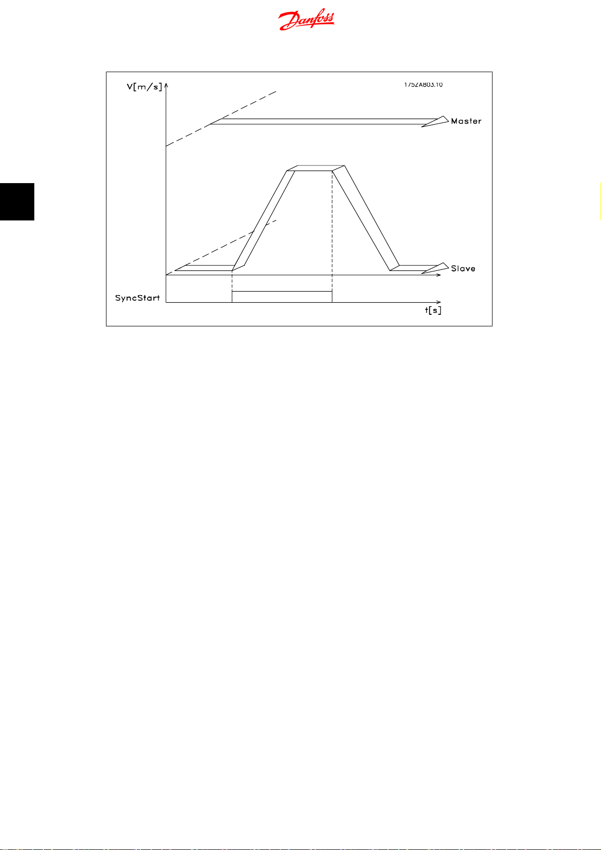
4
4. Synchronisation
Syncronising Controller MCO 350 Operating
Instructions
Illustration 4.2: Figure 10: SyncStart with speed synchronisation
4.2.2. Up/Down Factor
After the slave has been synchronised to the speed of the master by means of SyncStart (Terminal
I1), the gear ratio can be changed during operation. By means of Inputs 33 Speed+ / Up-factor,
or 32 Speed- / Down-factor, the gear ratio can be changed by the value set in par. 19-12
. This change affects only the slave factor. For more sensitive adjustment of the gear ratio,
width
the gear ratio digits should be extended and a small step width should be selected. If one of the
two inputs is on longer than the time defined in par. 19-11
cuted. Example: Gear ratio i = 22:43 If the step width is equal to 1, the first upward step will
result in i = 22:44, which represents almost 3 %. It would be better to set the ratio as i =
2200:4300. Then the upward step will result in i = 2200:4301, which represents a change of
approx. 0.03 %.
step time
step
, a further step will be exe-
48
MG.33.Q1.02 - VLT
®
is a registered Danfoss trademark

Syncronising Controller MCO 350 Operating
Instructions
4. Synchronisation
4
Illustration 4.3: Up/down factor with speed synchronisation
4.2.3. Hold Function
The Hold function operates the slave drive in closed loop speed control at a speed independent
of the master. With par. 19-02
speed set in par. 19-03 or whether it is to maintain current speed. For the duration of the Hold
signal, the speed of the master is no longer taken into account; the master can even stop without
this having any effect on the slave drive. While the Hold function is activated you can change the
speed with inputs 32 and 33. The speed is changing according to the settings in par. 19-04
hold speed
and par. 19-12
Hold function
Step width
you can choose whether the slave is to run at a fixed
Delta
.
MG.33.Q1.02 - VLT
®
is a registered Danfoss trademark
49

4
4. Synchronisation
Syncronising Controller MCO 350 Operating
Instructions
Illustration 4.4: Hold speed
4.2.4. Gear Changing
During synchronous operation, it is possible to switch between 4 fixed gear ratios, set in par. 19-05
to 19-07. The fixed gear ratios are selected at terminals 9 and 10:
Input 9 Input 10 Gear Ratio no.
0 0 0
01 1
1 0 2
11 3
To activate the new ratio you must activate
input I2. The newly set gear ratio is attained
with the minimum possible ramp.
50
MG.33.Q1.02 - VLT
®
is a registered Danfoss trademark

Syncronising Controller MCO 350 Operating
Instructions
4. Synchronisation
4
Illustration 4.5: Changing the gear ratio in speed synchronisation
4.2.5. Changing the Gear Ratio with an Analogue Value
As an alternative the gear ratio can be set via analogue input 54 with a +/- 10V signal, this function
is active when synchronising type 6 or 7 is selected in parameter 1901. The gear ratio denominator
is taken from the setting in gear 0. The gear ratio numerator is set by input 54, 5V corresponds
to 500. If you e.g. have set up 500 for masterfactor in gear 0, this would give a gear ratio of 1:1.
4.3. Application Examples - Admixture
A feed screw conveyor pump leads substance 1 to a nozzle adding substance 2. For different end
products it must be possible to select different mixing ratios (ratio 1 = 1:1; ratio 2 = 1:1.12; ratio
3 = 1:1.2; ratio 4 = 1:1.21). During operation it must be possible manually to make slight adjustments of the selected mixing ratio.
Description of terminals and terminal configuration
MG.33.Q1.02 - VLT
®
is a registered Danfoss trademark
51

4
4. Synchronisation
Syncronising Controller MCO 350 Operating
Instructions
4.3.1. Setting the Parameters
For this work it is recommended to have the description of parameters at hand. See the
AutomationDrive Programming Guide.
NB!
It is very important that the frequency converter is optimised for the motor before
optimising the synchronising controller:
1. Record the motor data and perform an AMA (Automatic Motor Adaptation) if possible.
2. Start programming the synchronisation functions.
52
MG.33.Q1.02 - VLT
VLT
®
is a registered Danfoss trademark

Syncronising Controller MCO 350 Operating
Instructions
Parameter No. 303
Maximum reference: Set the frequency for a value that is about 10% higher than the maximum
value of par. 32-80.
Example:
Motor
7.5kW,14601/
speed of the application approx
f
xN
Nom
Parameter No. 416
Torque limit for motor mode: Set for maximum. – Choose a lower value, if special safety precautions are necessary.
Parameter No. 417
Torque limit for regenerative operation: Set for maximum. – Choose a lower value, if special safety
precautions are necessary.
Application
N
Nom
x
1.1 =
min at
50
50Hz,
. 1800 1/
Hz x
1800
1460
1
min
62
H z maximum ref.value
min
1
min
=
4. Synchronisation
4
Parameter No. 33-80
Record “1” to start the test program.
Parameter No. 33-26
This parameter configures the velocity filter for speed synchronisation. Since speed synchronisation is based on speed a small fluctuation in master speed, when running at low speed, can have
an effect on the pid loop control. Hence this filter will even out the effect.
Cmdvel = Old_Cmdvel + (Actvel – Old_Cmdvel) * ms/tau_filt
Cmdvel = set velocity
Old_Cmdvel = last set velocity
Actvel = actual velocity of master
ms = sample time (parameter 32-69)
tau_filt = filter time constant
For standard encoders the following table can be used:
Encoder
Resolution
250 39500
256 38600
500 19500
512 19000
1000 9500
1024 9300
2000 4500
2048 4400
2500 3500
4096 1900
5000 1400
Tau_filt (ms)
Parameter No. 32-00/32-02
Record the type of slave encoder. Factory default is incremental encoder.
MG.33.Q1.02 - VLT
®
is a registered Danfoss trademark
53

4
4. Synchronisation
Parameter No. 32-01/32-03
Record the resolution of the slave encoder.
Parameter No. 32-30/32-32
Record the type of master encoder. Factory default is incremental encoder.
Parameter No. 32-31/32-33
Record the resolution of the master encoder.
Parameter No. 32-10
Record “No action” for clockwise rotation of both master and slave. Record “User units reversed”
if the slave is to run in the opposite direction.
Parameter No. 32-80
Record maximum RPM measured at the slave encoder.
Parameter No. 32-81
Minimum ramp: Set the time in Ms for the slave drive to accelerate from standstill to maximum
speed (par 3280). This value is important as this setting highly affects the control accuracy!
Syncronising Controller MCO 350 Operating
Instructions
Parameter No. 32-82
Ramp type: Record “0” for linear ramp and “1” for s-ramp. NOTE: S-ramp requires higher acceleration torque.
Parameter No. 32-68
Reversing behaviour: Record “0” if reversing is allowed, “1” if the slave must always follow the
direction of the master or “2” if reversion is not allowed.
4.3.2. How to Check the Motor Connection
When the above parameters have been programmed, check the motor connection as
follows:
1. Remove all signals to terminals 18-33 and I1-I10.
2. Press [Hand On] button on the LCP
3. Set the reference to a low value with the arrow keys (25 to 50 rpm). Please note that
the motor may now turn!
4. Press the [Off] button on the LCP to stop again. If the motor rotates in the wrong direction
then exchange the motor phases.
4.3.3. How to Test the Incremental Encoders
When you have tested the motor speed direction you test the incremental encoder
connection as follows: 1. 2. 3.
1. Remove all signals to terminals 18-33 and I1-I10.
2. Select parameter 34-50. The current actual position is then displayed.
3. Rotate the slave drive motor shaft manually in the forward direction. Now the display
shows an ascending count of the slave position. If the count is descending, exchange
the slave encoder track A by B and A/ by B/. If there is no counting in the display then
check the wiring of the encoder.
Follow the same procedure when testing the master encoder but use par. 34-52 for read-out of
the master position. Remember to push [Auto On] to return to normal control.
54
MG.33.Q1.02 - VLT
®
is a registered Danfoss trademark

Syncronising Controller MCO 350 Operating
Instructions
4.3.4. How to Optimise the Controller
synchronisation is obtained via two main elements of the controller: Velocity feed forward and the
PID controller.
NB!
Before starting the optimising procedures it is important to select the right type of
synchronisation in parameter 1904, in this example it must be “0” for velocity synchronisation. Please always have the necessary degree of accuracy in mind, you
could go on optimising for a long time, but it might not be necessary to have a 100%
accuracy in the application you are dealing with.
First step is to optimise velocity feed forward this can be done via the automatic calculation
function:
Velocity feed forward calculation is activated by setting parameter 19-05 to “1”, remember to
make the required parameter settings according to the description of par. 19-05 before starting
the calculation. The calculation is done when the value of par. 19-05 returns to “0”.
Velocity feed forward can also be optimised manually by the following procedure:
1. Set par. 32-64 PID bandwidth to “0”.
2. Set par. 32-67 maximum track error to a high value (e.g. 1,000,000).
3. Set par. 32-65 velocity feed forward to 100.
4. Start test-run with virtual master with a known velocity via input 3 = 1.
5. Increase parameter 3265 while watching master and slave velocity (press [Status] to get
the velocity readouts). You have found the optimal velocity feed forward when slave
velocity is approximately equal to the master velocity.
6. Stop test-run by input 3 = 0.
7. Reset parameter 3267 to the original value.
8. Reset parameter 3264 to 1000.
4. Synchronisation
4
Second step is to optimise the PID controller, a good starting point can be found be means of
the automatic calculation function:
By setting par. 19-05 to “2” velocity feed forward calculation is activated as well as calculation of
PID sample time and P/D factors, remember to make the required parameter settings according
to the description of par. 19-05 before starting the calculation. The calculation is done when the
value of par. 19-05 returns to “0”.
Using the test run functions can optimise the PID factors further:
There is two types of test run available: Positioning where the slave drive moves a specific distance
and synchronising with virtual master where the slave follows the virtual master in position or
spe e d . Ge n era l ly i t is b e t te r t o u se test run with virtual master as that comes closer to the operating
conditions in synchronising mode (program 2).
For test run with positioning the following parameters must be set:
Parameter No. 19-01
Test run speed: Record the speed as a percentage of the maximum speed of parameter 3280.
Parameter No. 19-02
Test run acceleration: record the acceleration time in per cent. 100% is minimum acceleration.
50% is half as fast as minimum acceleration, the ramp time will thus be twice as long.
MG.33.Q1.02 - VLT
®
is a registered Danfoss trademark
55

4
4. Synchronisation
Parameter No. 19-03
Test run distance: Record the distance (quad counts) for the drive to run during optimisation.
Then use the following procedure:
1. Close the contacts at terminal 32 (clockwise/forward direction) or terminal 33 (counter-
2. Increase the P-portion (par. 3260). After each change you should make a test run to find
3. Now set the D-portion (parameter 3261) to 5 times the value of parameter 3260.
4. If a lower synchronising error is required the I-portion (parameter 3262) can be set to a
For test run with virtual master the following parameters must be set:
Parameter No. 19-16
Virtual master reference: Select the reference source for setting the velocity of the virtual master.
“0” is analogue input 53, “1” is parameter 310 sub-index 0 and “2” is Fieldbus PCD 2.
Syncronising Controller MCO 350 Operating
Instructions
clockwise/reverse). During the test the last value of the first display line will indicate the
track error (PID error). After the test run is completed you can see the maximum track
error (PID error) in the display.
the right setting. If the drive becomes unsteady or if a message is given about overvoltage or over-current, then reduce the value in parameter 3260 to about 70-80% of
the set value.
low value e.g. 10 but be careful a too high value will course overshoot and instability.
Parameter No. 19-17
Virtual master acceleration: Set the acceleration of the virtual master in encoder pulses per sec-
2
.
ond
Parameter No. 19-18
Virtual master maximum speed: Set the maximum velocity of the virtual master in encoder pulses
per second.
Then use the following procedure:
1. Disconnect the master encoder from the synchronising controller (X56). Start test run
with virtual master by activating input 3. During test run you can read the track error in
the last value of the first display line. At stop the maximum track error during the test
run is read out. Because velocity synchronisation is selected (parameter 1904 = 0) the
track error is velocity deviance between master and slave.
2. If more accurate and dynamic control is required the P-portion (parameter 3260) must
be increased. If the slave becomes unstable the value must be reduced to by approximately 25%.
3. Now set the D-portion (parameter 3261) to 5 times the value of parameter 3260
4. If a lower synchronising error is required the I-portion (parameter 3262) can be set to a
low value e.g. 10 but be careful a too high value will course overshoot and instability.
The optimised values are automatically saved.
4.3.5. How to Programme Synchronisation
Change the value of parameter 33-80 to “2”. This will start the synchronisation application program. To do the synchronisation programming use the following parameters:
Parameter No. 19-01
Type of operation: Record “0” or “3” for speed synchronisation.
56
MG.33.Q1.02 - VLT
®
is a registered Danfoss trademark

Syncronising Controller MCO 350 Operating
Instructions
Parameter No. 19-02
Hold function: Specify how the drive is to react when Input 29 is activated . “Hold” switches the
drive from master synchronisation to a fixed frequency. Choose “0” to use the frequency set in
par. 1903 and “1” to use the current frequency.
Parameter No. 19-03
Hold speed: Set here, as a percentage of the maximum speed, the speed at which the drive should
move when you activate Hold and the value “0“ was selected in Parameter 1902.
Parameter No. 19-04
Delta hold speed: Set here the step width by which the hold speed is to be changed upwards or
downwards by activating Terminals 32 + 33.
Parameter No. 19-05
Gear ratio No.: Record the number of the gear ratio that is to be displayed in Parameters 1906 to
1907. Then you set the values required in Parameters 1906 to 1908. Follow the same procedure
for the next gear ratio(s).
Parameter No. 19-06
Gear ratio numerator: Record the numerator value of the gear ratio. That is the encoder pulses
of the slave drive. To make fine adjustment possible by means of inputs 32 and 33 a ratio of for
example 7:16 must be programmed as 7000:16000.
4. Synchronisation
4
Parameter No. 19-07
Gear ratio denominator: Enter here the denominator value of the gear ratio. This value corresponds to the master pulses.
Parameter No. 19-11
Step time: In Hold mode, the next frequency change and, in synchronisation mode, the next
change of the counter factor of the gear ratio, is carried out after this time, on the presence of
one of the signals at terminal 32 or 33. The time input is in milliseconds.
Parameter No. 19-12
Step width: In speed synchronisation, the gear ratio numerator is changed by this amount, if one
of the terminals 32 or 33 is closed.
Parameter No. 19-13
Slave speed factor: Record the factor by which the slave speed must be multiplied, so that it can
be displayed. Use the following formula:
N
x
400
Factor
set
=
xSlaveencoder_resolution
60
xDisplay_value
Example:
Factor
Resolution
1
min
x
400x1024
60
x
100
1500
=
Incr
Rev
.
.
= 102400
1024
increments,desired display
Parameter No. 19-14
Master speed factor: Record the factor by which the master speed must be multiplied, so that it
can be displayed. Use the following formula:
100at1500 1
Factor
N
set
=
x
400
xMasterencoder_resolution
60
xDisplay_value
MG.33.Q1.02 - VLT
®
is a registered Danfoss trademark
57

4
4. Synchronisation
Parameter No. 19-15
Synchronising error display factor: This factor must be 100, the synchronising error is then displayed in RPM related to the slave.
The settings are automatically saved.
4.4.1. Starting Synchronisation
Synchronisation with the master is achieved by closing the SyncStart contact (I1); the drive accelerates the maximum permitted acceleration to the speed of the master (calculated by means
of the gear ratio).
4.4.2. Stopping Synchronisation
When the SyncStart contact (I1) is opened, the slave is stopped at the permitted acceleration.
4.4.3. Fine Setting of the Gear Ratio
Fine setting of the gear ratio can now be undertaken by means of Inputs 32 + 33. This setting is
only temporary, i.e. the fine setting data will be lost as soon as the VLT is disconnected from the
mains. If the setting is to be saved, a Store operation must be carried out by closing the Store
contact (I4) or by means of Parameters 1900 before the VLT is switched off.
Syncronising Controller MCO 350 Operating
Instructions
4.4.4. Switching to Another Gear Ratio
During synchronisation, a new gear ratio can be selected at Inputs 9 and 10. The gear ratio is
then activated by means of the Switching Input (I2). The slave will then proceed at the permitted
acceleration to this new gear ratio.
4.4.5. Error Procedure
Errors of tracking, over current etc. make the drive stop and the Ready output (O8) is reset. Reset
is done with Input 27 or fieldbus bit 1.9. Reset is also possible with the [Reset] key of the local
control panel of the drive.
In case the drive has stopped because of earth fault or short-circuit, please cycle
the power to the drive from the mains before you reset!
4.5. Position Synchronisation
4.5.1. Position Synchronisation (angle synchronisation)
The position controller adjusts the slave drive position or angle to the master.
58
MG.33.Q1.02 - VLT
®
is a registered Danfoss trademark

Syncronising Controller MCO 350 Operating
Instructions
Illustration 4.6: Control behaviour with position synchronisation
4. Synchronisation
4
It appears from the diagram that the control accuracy depends on the master acceleration and
on the speed deviation between slave and master. A typical application for this type of synchronising could be the replacement of a mechanical shaft. Or mixing controls where a mixing rate is
required.
The following example shows how embossing patterns on moulds is controlled. This application
requires accurate position control.
MG.33.Q1.02 - VLT
®
is a registered Danfoss trademark
59
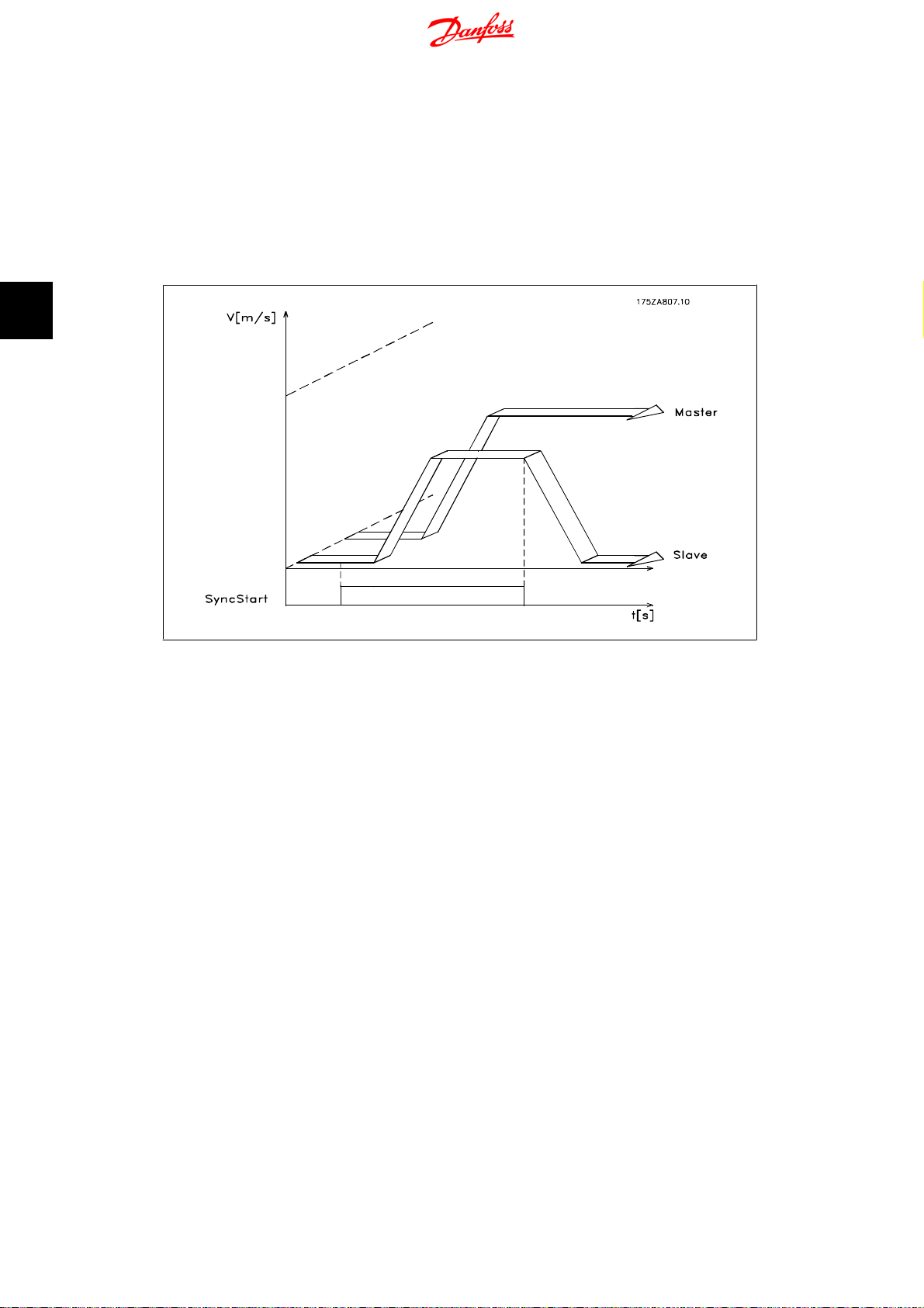
4
Syncronising Controller MCO 350 Operating
4. Synchronisation
4.6. Function Diagrams for Position Synchronisation
4.6.1. SyncStart to a Stationary Master
If the slave is synchronised to a stationary master drive, the slave will remain stationary. However,
if a fixed offset is defined for the activated gear ratio, the slave travels to the extent of this offset
during synchronisation.
Instructions
Illustration 4.7: synchronising to a stationary master
4.6.2. SyncStart to a Running Master
If synchronisation is effected to a running master, the slave drive first makes up the deviation of
distance then it proceeds synchronously with the master. Any Offset setting is taken into account.
60
MG.33.Q1.02 - VLT
®
is a registered Danfoss trademark

Syncronising Controller MCO 350 Operating
Instructions
4. Synchronisation
4
Illustration 4.8: synchronising to a running master
4.6.3. Position Displacement with a Running Master
If one of the Inputs 32 or 33 is activated during synchronous travel, the actual position in relation
to the master is displaced by the value set in Parameter 1910. If the displacement is positive, the
slave accelerates in order to travel the necessary distance in order then again to travel synchronously to the master at the speed determined via the gear ratio. If the displacement is negative,
the slave decelerates in order to attain the necessary distance to then again travel synchronously
with the master at the speed determined via the gear ratio.
Illustration 4.9: Position displacement
MG.33.Q1.02 - VLT
®
is a registered Danfoss trademark
61

4
Syncronising Controller MCO 350 Operating
4. Synchronisation
4.7.1. Application Example - Embossing Patterns on Mould
Moulds of two different kinds and lengths are embossed with a pattern. The conveyor belt operator
changes the position of the pattern by means of two buttons. Each of the two incremental encoders has a zero track for marker synchronisation.
4.7.2. Description of Terminals and Terminal Configuration
Instructions
62
MG.33.Q1.02 - VLT
®
is a registered Danfoss trademark

Syncronising Controller MCO 350 Operating
Instructions
4.7.3. Setting the Parameters
4. Synchronisation
For this work it is recommended to have the description of parameters at hand. See the
VLT
Automation Drive Operating Instructions.
NB!
It is very important that the VLT is optimised for the motor before optimising the synchronising controller:
1. Record the motor data and perform an AMA (Automatic Motor Adaptation)
if possible.
2. Start programming the synchronisation functions.
Parameter No. 303
Maximum reference: Set the frequency for a value that is about 10% higher than the maximum
value of par.32-80.
Example: Motor 7.5 kW, 1460 1/min at 50 Hz, speed of the application approx. 1800 1/min
50
f
xN
Nom
=62
Parameter No. 416
Torque limit for motor mode: Set for maximum. – Choose a lower value, if special safety precautions are necessary.
Application
N
Nom
x
1, 1 =
Hz Maximum ref.value
Hz x
1460
1800
1
min
1
min
x
1, 1
4
Parameter No. 417
Torque limit for regenerative operation: Set for maximum. – Choose a lower value, if special safety
precautions are necessary.
Parameter No. 33-80
Record “1” to start the test program.
Parameter No. 33-26
When performing position synchronisation this parameter is used to insert a filter to compensate
for an oscillating master signal. If, for example, the master is experiencing shock loads the pid
loop of the synchronising controller will have a tendency to oscillate as well. A negative value must
be entered.
Example: If a filter factor of –100000 (100 ms) is used the correction is balanced within: 1000/
(filter factor *10)= 1 second.
Parameter No. 32-00/32-02
Record the slave encoder type. “0” represents the incremental encoder.
Parameter No. 32-01/32-03
Record the resolution of the slave encoder.
Parameter No. 32-30/32-32
Record the master encoder type. “0” represents the incremental encoder.
Parameter No. 32-31/32-33
Record the resolution of the master encoder.
MG.33.Q1.02 - VLT
®
is a registered Danfoss trademark
63

4
4. Synchronisation
Parameter No. 32-10
Record “No action” for clockwise rotation of both master and slave. Record “User units reversed”
if the slave is to run in the opposite direction.
Parameter No. 32-80
Record maximum RPM measured at the slave encoder.
Parameter No. 32-81
Minimum ramp: Set the time in ms for the slave drive to accelerate from standstill to maximum
speed (par 3280). The value is important, as this setting highly affects the control accuracy!
Parameter No. 32-82
Ramp type: Record “0” for linear ramp and “1” for s-ramp. Note: S-ramp requires higher acceleration torque
Parameter No. 32-67
Maximum track error: Record the value that is to generate “Track error” indication in the display,
if exceeded. Input is in quad counts.
Syncronising Controller MCO 350 Operating
Instructions
Parameter No. 32-68
Reversing behaviour: Record “0” if reversing is allowed, “1” if the slave must always follow the
direction of the master or “2” if reversing is not allowed.
The settings are automatically saved.
4.7.4. How to Check the Motor Connection
When the above parameters have been programmed, check the motor connection as
follows:
Remove all signals to terminals 18-33 and I1-I10
Press [Hand On] button on the LCP.
Set the reference tor a low value with the arrow kkeys (25 to 50 rpm).
Please note that the motor may now turn
Press the [Off] button on the LCP to stop again. If the motor rotates in the wrong direction
then exchange the motor phases.
4.7.5. How to Test the Incremental Encoders
After testing the motor speed direction, test the incremental encoder connection as
follows:
1. Remove all signals to terminals 18-33 and I1-I10.
2. Select parameter 3450. The current actual position is then displayed.
3. Rotate the slave drive motor shaft manually in the forward direction. Now the display
shows an ascending count of the slave position.
4. If the count is descending, exchange the slave encoder track A by B and A/ by B/.
5. If there is no counting in the display then check the wiring of the encoder.
Follow the same procedure when testing the master encoder but use parameter 34-52 for readout of the master position. Remember to push [Auto On] to return to normal control.
64
MG.33.Q1.02 - VLT
®
is a registered Danfoss trademark

Syncronising Controller MCO 350 Operating
Instructions
4.7.6. How to Optimise the Controller
Synchronisation is obtained via two main elements of the controller: Velocity feed forward and
the PID controller.
NB!
Before starting the optimising procedures it is important to select the right type of
synchronisation in parameter 1904, in this example it must be “1” for position synchronisation. Please always have the necessary degree of accuracy in mind, you
could go on optimising for a long time, but it might not be necessary to have a 100%
accuracy in the application you are dealing with.
First step is to optimise velocity feed forward this can be done via the automatic calculation
function: Velocity feed forward calculation is activated by setting parameter 1905 to “1”, remember to make the required parameter settings according to the description of par. 1905 before
starting the calculation. The calculation is done when the value of par. 1905 returns to “0”.
Velocity feed forward can also be optimised manually by the following procedure:
Set parameter 3264 PID bandwidth to “0”.
Set parameter 3267 maximum track error to a high value (e.g. 1.000.000).
Set parameter 3265 velocity feed forward to 100.
Start test-run with virtual master with a known velocity via input 3 = 1.
Increase parameter 3265 while watching master and slave velocity (press [DISPLAY/
STATUS] to get the velocity readouts). The optimal velocity feed forward has been identified when the slave velocity is approximately equal to the master velocity.
Stop test-run by input 3 = 0.
Reset parameter 3267 to the original value.
Reset parameter 3264 to 1000.
Second step is to optimise the PID controller, a good starting point can be found be means of
the automatic calculation function: By setting parameter 1905 to “2” velocity feed forward calculation is activated as well as calculation of PID sample time and P/D factors, remember to make
the required parameter settings according to the description of par. 1905 before starting the calculation. The calculation is done when the value of par. 1905 returns to “0”.
4. Synchronisation
4
Using the test run functions optimises the PID factors further:
Two types of test runs are available: Positioning where the slave drive moves a specific distance
and synchronising with virtual master where the slave follows the virtual master in position or
spe e d . Ge n era l ly i t is b e t te r t o u se test run with virtual master as that comes closer to the operating
conditions in synchronising mode (program 2).
For test run with positioning the following parameters must be set:
Parameter No. 1901
Test run speed: Record the speed as a percentage of the maximum speed of parameter 3280.
Parameter No. 1902
Test run acceleration: record the acceleration time in per cent. 100% is minimum acceleration.
50% is half as fast as minimum acceleration, the ramp time will thus be twice as long.
Parameter No. 1903
Test run distance: Record the distance (quad counts) for the drive to run during optimisation.
MG.33.Q1.02 - VLT
®
is a registered Danfoss trademark
65

4
4. Synchronisation
Then use the following procedure:
1. Close the contacts at terminal 32 (clockwise direction) or terminal 33 (counter-clockwise).
2. Increase the P-portion (par. 3260). After each change you should make a test run to find
3. Now set the D-portion (parameter 3261) to 5 times the value of parameter 3260.
4. If a lower synchronising error is required the I-portion (parameter 3262) can be set to a
For test run with virtual master the following parameters must be set:
Parameter No. 19-16
Virtual master reference: Select the reference source for setting the velocity of the virtual master.
“0” is analogue input 53, “1” is parameter 310 sub-index 0, “2” is Fieldbus PCD 2.
Syncronising Controller MCO 350 Operating
Instructions
During the test the last value of the first display line will indicate the track error (PID
error). After the test run is completed you can see the maximum track error (PID error).
the right setting. If the drive becomes unsteady or if a message is given about overvoltage or over-current, then reduce the value in parameter 3260 to about 70-80% of
the set value.
low value e.g. 10 but be careful a too high value will course overshoot and instability
Parameter No. 19-17
Virtual master acceleration: Set the acceleration of the virtual master in encoder pulses per sec-
2
ond
.
Parameter No. 19-18
Virtual master maximum speed: Set the maximum velocity of the virtual master in encoder pulses
per second.
Then use the following procedure:
1. Start test run with virtual master by activating input 3. During test run you can read the
track error in the last value of the first display line. At stop the maximum track error
during the test run is read out.
2. If more accurate and dynamic control is required the P-portion (parameter 3260) must
be increased. If the slave becomes unstable the value must be reduced to by approximately 25%.
3. Now set the D-portion (parameter 3261) to 5 times the value of parameter 3260
4. If a lower synchronising error is required the I-portion (parameter 3262) can be set to a
low value e.g. 10 but be careful a too high value will course overshoot and instability.
The settings are automatically saved.
4.7.7. How to Programme Synchronisation
Change the value of parameter 33-80 to “2”. This will start the synchronisation program of VLT.
To do the synchronisation programming you use the following parameters:
Parameter No. 19-01
Type of operation: Record “1” or “4” for position synchronisation.
Parameter No. 33-00
Home function, used together with par 30-04: Specify the start function of the drive: “0” Homerun not forced “1” Home run must be carried out before the first start of synchronisation
Parameter No. 33-02
Home acceleration: Set the acceleration (% of minimum acceleration) for homing.
66
MG.33.Q1.02 - VLT
®
is a registered Danfoss trademark

Syncronising Controller MCO 350 Operating
Instructions
Parameter No. 30-03
Home speed: Set the speed (% of maximum speed) at which Homing is to be made. Positive
values for clockwise rotation, negative values for counter-clockwise rotation.
Parameter No. 30-04
Home force function:
0 = The homing only has to be carried out after power up
1-3 = The homing has to be carried out before every sync start
Parameter No. 33-13
Accuracy: Record a value (quad counts) for a tolerance within which the slave position may deviate
from the position of the master. With a negative value the synchronising error (parameter 1993)
show the error with a sign.
Parameter No. 33-24
Marker quantity Fault: Inaccuracy: Record the number of marker signals to generate a Fault signal.
Parameter No. 33-25
Marker quantity Ready: Accuracy: Record the number of marker signals to generate a Ready
signal.
4. Synchronisation
4
Parameter No. 19-05
Gear ratio No.: Record the number of the gear ratio that is to be displayed in Parameters 1906 to
1907. First set the number of the gear ratio, then the necessary values for this gear ratio can be
set in Parameters 1906 and 1907. The next gear ratio is then selected in Parameter 1905 and the
same procedure is repeated.
Parameter No. 19-06
Gear ratio numerator: Enter here the numerator value of the gear ratio. The value corresponds
to the encoder pulses of the slave drive. To make fine adjustment possible by means of inputs 32
and 33 a ratio of for example 7:16 must be programmed as 7000:16000.
Parameter No. 19-07
Gear ratio denominator: Record the denominator value of the gear ratio. This value corresponds
to the master pulses.
Parameter No. 19-10
Fixed Offset: Record a fixed position offset for the selected gear ratio (quad counts). You use this
value to specify the position deviation between slave and master. During operation you can change
the value by means of inputs 32 and 33. Note: Offset is related to the master position. Offset
related to the slave position can be calculated as follows:
O ffset_slave
Parameter No. 19-11
Step time: Record the delay in ms from one frequency change to another (hold mode) and from
one gear ratio numerator factor change to another (synchronisation mode) when there is a signal
on terminal 32 or 33.
O ffset x Par
=
Par
. 738
. 739
Parameter No. 19-12
Step width: Record a value to specify the position displacement between slave and master.
Parameter No. 19-13
MG.33.Q1.02 - VLT
®
is a registered Danfoss trademark
67

4. Synchronisation
Slave speed factor: Record the factor by which the slave speed must be multiplied, so that the
desired value is displayed. To calculate the value use the following formula:
Factor
Example:
Resolution 1024 increments, desired display 100 at 15001/min
Syncronising Controller MCO 350 Operating
Instructions
N
x
400
Set
=
x Slaveencoder_resolution
60
xDisplay_value
4
1500
Factor
Parameter No. 19-14
Master speed factor: Record the factor by which the master speed must be multiplied, so that the
desired value is displayed. To calculate the value use the following formula:
Factor
Parameter No. 19-15
Synchronisation error display factor: Record the factor by which the error must be multiplied, so
that the desired value is displayed. To calculate the value use the following formula:
Factor
=
=
=
1
400x1024
x
min
x
100
60
N
x
400
Set
N
x
Set
x Slaveencoder_resolution
60
xDisplay_value
400
x Slaveencoder_resolution
60
xDisplay_value
Incr
Rev
.
.
= 102400
The settings are automatically saved.
4.7.8. Operation and Operating Functions
After all values have been set as described and the controller has been optimised for the application, Parameter 3004 Home function is set to the value of “2”. The drive can now be operated
normally.
Home run
As parameter 33-00 is set to “1” and parameter 33-04 is set to “2” homing must be carried out
before each start. To start homing the contact at Terminal 19 is closed. The slave drive then travels
to the home switch and stops there. If the reversing procedure is set to “0”, the slave travels back
to the start of the home switch; otherwise, the offset arising from disabling reversing is added to
the fixed offset.
Starting synchronisation
Preferably, the master is first similarly brought into its start position and the slave activated by
means of I1 (SyncStart), then the master is started. This produces optimum synchronisation. The
slave can, of course, also be started by, e.g. a start signal from the master, although in that case
it should be noted that the delay of the start signal can be prolonged by the scan time of e.g. the
PLC. Attention should be paid to the accuracy of the start signal. Hence, it is better to start the
slave drive when the master is in position. The position of the master, plus the value of the fixed
offset, is the synchronisation position to which the slave drive will travel at the maximum permitted
acceleration when started. It may happen here that the slave drive travels faster than the master,
as the slave drive needs to catch up with the master position.
Stopping synchronisation
On opening the SyncStart contact (I1), the slave is stopped at the permitted acceleration. Because
Home force function is set at “2”, a new start is only possible after a renewed Home run.
Fine setting of the position
68
MG.33.Q1.02 - VLT
®
is a registered Danfoss trademark

Syncronising Controller MCO 350 Operating
Instructions
As soon as the slave drive is in position synchronisation to the master, a displacement of this
position can be effected by means of Inputs 32 + 33. Offset is related to the master position.
Offset related to the slave position can be calculated as follows:
4. Synchronisation
O ffset_slave
Switching to another gear ratio
During synchronisation, a new gear ratio can be selected at Inputs 9 and 10. The gear ratio is
then activated by means of Input (I2). The slave will then proceed at the permitted acceleration
to this new gear ratio. The offset is related to the first gear ratio after SyncStart. Therefore a stop
and then start must be performed if the offset must relate to the latest gear ratio it the gear ratio
has been changed.
Error procedure
Errors of tracking, over current etc. make the drive stop. The Ready output (O8) is set low. Reset
is done with Input 27 or fieldbus bit 1.9. Reset is also possible with of the [Reset] button on the
local control panel of the drive.
O ffset x Par
=
In case the drive has stopped because of earth fault or short-circuit, disconnect the
drive from the mains before resetting!
Par
.19− 06
.19− 07
4.8. Marker Synchronisation - Function Diagrams for
Marker Synchronisation
4
4.8.1. Marker Synchronising
Using Marker synchronising the start position is not predefined. The Marker will alter the position
during operation, as required. Marker synchronising is for example used to compensate for any
undesired slip.
Illustration 4.10: Control behaviour with marker synchronisation
It appears from the diagram that the control accuracy depends on the master acceleration and
on the speed deviation between slave and master.
MG.33.Q1.02 - VLT
®
is a registered Danfoss trademark
69

4
4. Synchronisation
The following example shows the use of marker synchronisation to compensate for friction slip
that can arise from dropping a box onto Conveyor belt 1. By means of marker correction in the
form of object recognition, the slave belt is controlled so that the product will always be placed
right in the middle of the box, even if the box itself is not centrally positioned in its conveyor
compartment.
Syncronising Controller MCO 350 Operating
Instructions
Illustration 4.11: Conveyor belt with marker synchronisation
4.8.2. SyncStart to a Running Master after Power ON
If the slave is synchronised to a running master drive, the slave automatically synchronises its
position to the master. After at least one slave marker and one master marker have been detected,
the marker compensation comes into effect.
70
MG.33.Q1.02 - VLT
®
is a registered Danfoss trademark

Syncronising Controller MCO 350 Operating
Instructions
4. Synchronisation
4
Illustration 4.12: Initial start-up with marker synchronisation
4.8.3. Marker Correction during Operation
During operation, marker correction is always carried out when the markers is detected. This
ensures optimum synchronisation, no matter whether the gear ratios are not accurate or there is
a slip.
Illustration 4.13: Marker correction during operation
4.9. Application Example - Packaging
This example is a conveyor belt with cardboard boxes of low weight and different lengths. To
ensure that the components to be packed are placed right in the middle of the boxes you must
use synchronisation with marker correction. The grab belt is controlled by position synchronisation
MG.33.Q1.02 - VLT
®
is a registered Danfoss trademark
71

4
4. Synchronisation
and as soon as one of the two markers is recognised, the grab belt is either moved forward to the
conveyor belt position or slowed down. It is also possible for the operator to change the position
by means of two push buttons.
4.9.1. Terminals and Terminal Configuration
Syncronising Controller MCO 350 Operating
Instructions
Wiring diagram - conveyor belt regulation
4.9.2. Setting the Parameters
For this purpose it is recommended to have the parameter descriptions at hand. See the
Automation Drive FC 300 Operating Instructions.
72
MG.33.Q1.02 - VLT
VLT
®
is a registered Danfoss trademark

Syncronising Controller MCO 350 Operating
Instructions
NB!
It is very important that the VLT is optimised for the motor before optimising the
synchronising controller. First, record the motor data and perform an AMA (Automatic Motor Adaptation) if possible. Then start programming the synchronisation
functions
Parameter No. 303
Maximum reference: Set the frequency for a value that is about 10% higher than the maximum
value of parameter 32-80.
Example: Motor 7.5kW, 1460 1/min at 50Hz, speed of the application approx. 1800 1/min
f
xN
Nom
=62
Parameter No. 33-80
Record “1” to start the test program.
Application
N
Nom
x
1.1 =
H z maximum ref.value
50
Hz x
1460
1800
1
min
1
min
4. Synchronisation
4
x
1.1
Parameter No. 33-26
When performing position synchronisation this parameter is used to insert a filter to compensate
for an oscillating master signal. If, for example, the master is experiencing shock loads the pid
loop of the synchronising controller will have a tendency to oscillate as well. A negative value must
be entered.
Example: If a filter factor of –100000 (100 ms) is used the correction is balanced within: 1000/
(filter factor *10)= 1 second.
Parameter No. 32-00/32-02
Record the slave encoder type. “0” represents an incremental encoder.
Parameter No. 32-01/32-03
Record the resolution of the slave encoder.
Parameter No. 32-30/32-32
Record the master encoder type. “0” represents an incremental encoder.
Parameter No. 32-31/32-33
Record the resolution of the master encoder.
Parameter No. 32-10
Direction of rotation: Record “1” for clockwise rotation of the slave. Record “-1” if the slave is to
run in the opposite direction.
Parameter No. 32-80
Record maximum RPM measured at the slave encoder.
Parameter No. 32-81
Minimum ramp: Set the time in ms for the slave drive to accelerate from standstill to maximum
speed (par. 3280). Consider the value carefully as this setting will highly affect the control accuracy!
Parameter No. 32-82
Ramp type: Record “0” for linear ramp and “1” for s-ramp. NOTE: S-ramp requires higher acceleration torque.
MG.33.Q1.02 - VLT
®
is a registered Danfoss trademark
73

4
4. Synchronisation
Parameter No. 32-67
Maximum track error: Record the value that is to generate “Track error” indication in the display,
if exceeded.
Parameter No. 32-68
Reversing procedure: Record “0” if reversing is allowed, “1” if the slave must always follow the
direction of the master or “2” if reversing is not allowed.
Parameter No. 33-20
Slave marker type: As external marker signals are used, you can set the type of edge triggering
of the external marker signal; “2” for a positive edge, “3” for a negative edge.
Parameter No. 33-18
Slave marker interval: Record the interval between two marker signals of the slave. Input of the
interval is in quad counts. If the interval is not known, it can also be determined during the test
run.
Parameter No. 33-19
Master marker type: As external marker signals are used, you can set the type of edge triggering
of the external marker signal here; “2” for a positive edge, “3” for a negative edge.
Syncronising Controller MCO 350 Operating
Instructions
Parameter No. 33-17
Master marker interval: Record the interval between two marker signals of the master. Input of
the interval is in quad counts. If the interval is not known, it can also be determined during the
test run.
Parameter No. 19-01
Test run speed: Record the speed at which you want to carry out the optimisation run. Record
the speed as a percentage of the speed in Parameter 3280.
Parameter No. 19-02
Test run acceleration: Record the acceleration for the test run in percent of the minimum acceleration time. 100% represents the minimum acceleration, 50% is half as fast as minimum
acceleration; the ramp time is thus twice as long.
Parameter No. 19-03
Test run distance: Record the distance (quad counts) for the drive to travel during optimisation.
4.9.3. How to Check the Motor Connection
After programming the above parameters, check the motor connectio n as follows:
1. Remove all signals to terminals 18-33 and I1-I10.
2. Press [Hand On] button on the LCP.
3. Set the reference to a low value with the arrow keys (25 to 50 rpm).
4. Press the [Off] button on the LCP to stop again. If the motor rotates in the wrong direction
then exchange the motor phases.
How to test the incremental encoders When you have tested the motor speed direction you test
the incremental encoder connection as follows: 1. Remove all signals to terminals 18-33 and I1I10. 2. Select parameter 3450. The current actual position is then displayed, 3. Rotate the slave
drive motor shaft manually in the forward direction. Now the display shows an ascending count
of the slave position. If the count is descending, exchange the slave encoder track A by B and A/
by B/. If there is no counting in the display then check the wiring of the encoder. Follow the same
74
MG.33.Q1.02 - VLT
®
is a registered Danfoss trademark

Syncronising Controller MCO 350 Operating
Instructions
procedure when you test the master encoder but use parameter 3452 for read-out of the master
position. Remember to push [Auto On] to return to normal control.
4.9.4. How to Test the Incremental Encoders
After testing the motor speed direction, test the incremental encoder connection as
follows:
1. Remove all signals to terminals 18-33 and I1-I10.
2. Select parameter 34-50. The current actual position is then displayed
3. Rotate the slave drive motor shaft manually in the forward direction. Now the display
shows an ascending count of the slave position. If the count is descending, exchange
the slave encoder track A by B and A/ by B/. If there is no counting in the display then
check the wiring of the encoder.
Follow the same procedure when testing the master encoder but use parameter 34-52 for readout of the master position. Remember to push [Auto On] to return to normal control.
4.9.5. How to Optimise the Controller
4. Synchronisation
4
Synchronisation is obtained via two main elements of the controller: Velocity feed forward and
the PID controller.
NB!
Before starting the optimising procedures it is important to select the right type of
synchronisation in parameter 1904, in this example it must be “1” for position synchronisation. Please always have the necessary degree of accuracy in mind, you
could go on optimising for a long time, but it might not be necessary to have a 100%
accuracy in the application you are dealing with.
First step is to optimise velocity feed forward this can be done via the automatic calculation
function:
Velocity feed forward calculation is activated by setting parameter 1905 to “1”, remember to make
the required parameter settings according to the description of par. 1905 before starting the calculation. The calculation is done when the value of par. 1905 returns to “0”.
Velocity feed forward can also be optimised manually by the following procedure:
1. Set parameter 3264 PID bandwidth to “0”.
2. Set parameter 3267 maximum track error to a high value (e.g. 1.000.000).
3. Set parameter 3265 velocity feed forward to 100.
4. Start test-run with virtual master with a known velocity via input 3 = 1.
5. Increase parameter 3265 while watching master and slave velocity (press [DISPLAY/
STATUS] to get the velocity readouts). You have found the optimal velocity feed forward
when slave velocity is approximately equal to the master velocity.
6. Stop test-run by input 3 = 0.
7. Reset parameter 3267 to the original value.
8. Reset parameter 3264 to 1000.
Second step is to optimise the PID controller, a good starting point can be found be means of
the automatic calculation function:
By setting parameter 1905 to “2” velocity feed forward calculation is activated as well as calculation
of PID sample time and P/D factors, remember to make the required parameter settings according
to the description of par. 1905 before starting the calculation. The calculation is done when the
value of par. 1905 returns to “0”.
MG.33.Q1.02 - VLT
®
is a registered Danfoss trademark
75

4
4. Synchronisation
Using the test run functions can optimise the PID factors further:
There is two types of test run available: Positioning where the slave drive moves a specific distance
and synchronising with virtual master where the slave follows the virtual master in position or
speed. Generally it is better to use test run with virtual master as that comes closer to the operating
conditions in synchronising mode (program 2).
For test run with positioning the following parameters must be set:
Parameter No. 19-01
Test run speed: Record the speed as a percentage of the maximum speed of parameter 3280.
Parameter No. 19-02
Test run acceleration: record the acceleration time in per cent. 100% is minimum acceleration.
50% is half as fast as minimum acceleration, the ramp time will thus be twice as long.
Parameter No. 19-03
Test run distance: Record the distance (quad counts) for the drive to run during optimisation.
Then use the following procedure:
1. Close the contacts at terminal 32 (clockwise direction) or terminal 33 (counter-clockwise).
2. Increase the P-portion (par. 3260). After each change you should make a test run to find
3. Now set the D-portion (parameter 3261) to 5 times the value of parameter 3260.
4. If a lower synchronising error is required the I-portion (parameter 3262) can be set to a
For test run with virtual master the following parameters must be set:
Syncronising Controller MCO 350 Operating
Instructions
During the test the last value of the first display line will indicate the track error (PID
error). After the test run is completed you can see the maximum track error (PID error).
the right setting. If the drive becomes unsteady or if a message is given about overvoltage or over-current, then reduce the value in parameter 3260 to about 70-80% of
the set value.
low value e.g. 10 but be careful a too high value will course overshoot and instability
Parameter No. 19-16
Virtual master reference: Select the reference source for setting the velocity of the virtual master.
“0” is analogue input 53, “1” is parameter 310 sub-index, “2” is Fieldbus PCD 2.
Parameter No. 19-17
Virtual master acceleration: Set the acceleration of the virtual master in encoder pulses per sec-
2
ond
.
Parameter No. 19-18
Virtual master maximum speed: Set the maximum velocity of the virtual master in encoder pulses
per second.
Then use the following procedure:
1. Start test run with virtual master by activating input 3. During test run you can read the
track error in the last value of the first display line. At stop the maximum track error
during the test run is read out.
2. If more accurate and dynamic control is required the P-portion (parameter 3260) must
be increased. If the slave becomes unstable the value must be reduced to by approximately 25%.
3. Now set the D-portion (parameter 3261) to 5 times the value of parameter 3260.
4. If a lower synchronising error is required the I-portion (parameter 3262) can be set to a
low value e.g. 10 but be careful a too high value will course overshoot and instability.
76
MG.33.Q1.02 - VLT
®
is a registered Danfoss trademark

Syncronising Controller MCO 350 Operating
Instructions
If the interval between two marker signals at the slave is not known, this interval can now be
measured. To do this, the contact at the Slave marker search input (I8) is closed. The slave drive
now rotates at the set test run speed. With each master signal, the interval can be read off in
Parameter 3318. If the marker search is stopped by opening the Slave marker search contact (I8),
an average of all the marker intervals is taken, and this is entered as the value in Parameter 3318.
Similarly, the intervals between the marker signals of the master drive are measured by means
of the Master marker search input (I7). To do this, it is necessary to start the master. The intervals
are continuously displayed in Parameter 3317. After opening the Master marker search contact
(I7), the calculated average of all the measurements is again entered as the final result in Parameter 3317.
4. Synchronisation
The settings are automatically saved.
4.9.6. How to Programme Synchronisation
Change the value of parameter 33-80 to “2”. This will start the synchronisation application program.
Use the following parameters to programme the synchronisation:
Parameter No. 19-01
Type of operation: Record “2” or “5” for marker synchronisation.
Parameter No. 33-23
Marker synchronisation behaviour: Specify here how the slave drive is to react while synchronising
to the master marker. “0” means the last marker pulse of the master - the slave synchronises to
the last master marker pulse already registered - it catches up. “1” means the next master marker
pulse - the slave waits for the next master marker and synchronises to it - the slave slows down.
“2” means that the slave uses the nearest master marker - it decides for itself whether to catch
up or slow down.
Parameter No. 33-13
Accuracy: Record a value (quadcounts) for a tolerance within which the slave position may deviate
from the position of the master.
4
Parameter No. 33-24
Marker quantity Fault: Inaccuracy: Record the number of market signals to generate a Fault signal.
Parameter No. 33-25
Marker quantity Ready: Accuracy: Record the number of marker signals to generate a Ready
signal.
Parameter No. 19-05
Gear ratio No.: Record the number of the gear ratio that is to be displayed in Parameters 1906 to
1910. First set the number of the gear ratio, then in Parameters 1906 to 1910 the necessary values
for this gear ratio. The next gear ratio is then selected in Parameter 1905 and the same procedure
is repeated.
Parameter No. 19-06
Gear ratio numerator: Record the numerator value for the gear ratio. That is the encoder pulses
of the slave drive. To make fine adjustment possible by means of inputs 32 and 33 a ratio of for
example 7:16 must be programmed as 7000:16000.
MG.33.Q1.02 - VLT
®
is a registered Danfoss trademark
77

4
4. Synchronisation
Parameter No. 19-07
Gear ratio denominator: Record the denominator value of the gear ratio. This value corresponds
to the master pulses.
Parameter No. 19-08
Slave markers: Record the number of slave markers for the marker ratio. Ensure that the gear
ratio and the marker ratio match each other.
Parameter No. 19-09
Master markers: Record the number of master markers for the marker ratio. Ensure that the gear
ratio and the marker ratio match each other.
Parameter No. 19-10
Fixed Offset: Record a fixed position offset for the selected gear ratio (quad counts). This value
specifies the position deviation between the slave marker and the master marker. During operation
the offset can be changed by means of inputs 32 and 33. Note: Offset is related to the master
position.
Offset related to the slave position can be calculated as follows:
Syncronising Controller MCO 350 Operating
Instructions
Offset_slave
Parameter No. 19-11
Step time: Record the delay in ms from one frequency change to another (hold mode) and from
one gear ratio numerator factor change to another (synchronisation mode) when there is a signal
on terminal 32 or 33.
Parameter No. 19-12
Step width: In marker synchronisation mode, Offset Parameter 1908 is changed by this value
when Terminal 32 or Terminal 33 is activated.
Parameter No. 19-13
Slave speed factor: Record the factor by which the slave speed must be multiplied, so that the
desired value is displayed. To calculate the value use the following formula:
Factor
Example:
resolution 1024 increments, desired display
100 at 15001/min
Factor
Parameter No. 19-14
Master speed factor: Record the factor by which the master speed must be multiplied, so that the
desired value is displayed.
To calculate the value use the following formula:
=
=
=
N
Set
1500
x
Offset x Par
Par
400
x Slaveencoder_resolution
60
1
x
min
60x100
.19− 06
.19− 07
xDisplay_value
400x1024
Umdr
Inkr
= 102400
N
x
400
Factor
Parameter No. 19-15
Synchronising error display factor: Record the factor by which the error must be multiplied, so
that the desired value is displayed.
To calculate the value, use the following formula:
78
MG.33.Q1.02 - VLT
Set
=
x Slaveencoder_resolution
60
xDisplay_value
®
is a registered Danfoss trademark

Syncronising Controller MCO 350 Operating
Instructions
N
x
400
Factor
The settings are automatically saved.
Set
=
xSlaveencoder_resolution
60
xDisplay_value
4.9.7. Operation and Operating Functions
After all the values have been set as described, the drive can now be operated normally.
Starting synchronisation
Synchronisation of the slave is started by means of SyncStart (I1), then the master is started. This
ensures optimum synchronisation. The slave drive travels in position synchronisation to the master
until both slave and master marker has been detected. The slave accelerates or slows down,
according to the setting of Parameter 3323, in order to attain the marker position plus the set
offset. It may happen that the slave drive travels faster than the master does, if the slave drive
needs to catch up with the position.
Stopping synchronisation
On opening contact I1 (SyncStart), the slave is stopped at the permitted acceleration.
4. Synchronisation
4
Fine setting of the position
As soon as the slave drive is in position synchronisation to the master, an adjustment of this
position can be made by means of Inputs 32 + 33. Note: Offset is related to the master position.
Offset related to the slave position can be calculated as follows:
O ffset_slave
Switching to another gear ratio
During synchronisation, a new gear ratio can be selected at Inputs 9 and 10. The gear ratio is
then activated by means of the Switching Input (I2). The slave will then proceed at the permitted
acceleration to this new gear ratio. The offset is related to the first gear ratio after SyncStart.
Therefore a stop and then start must be performed if the offset must relate to the latest gear ratio
it the gear ratio has been changed.
Error procedure
Errors of tracking, over current etc. make the drive stop and the Ready output (O8) is set low.
Reset is done with Input 27 or fieldbus bit 1.9. Reset is also possible with of the [Reset] button
on the local control panel of the drive.
O ffset x Par
=
In case the drive has stopped because of earth fault or short-circuit, disconnect the
drive from the mains before resetting!
Par
.19− 06
.19− 07
MG.33.Q1.02 - VLT
®
is a registered Danfoss trademark
79

5
5. Appendix
Syncronising Controller MCO 350 Operating
Instructions
80
MG.33.Q1.02 - VLT
®
is a registered Danfoss trademark

Syncronising Controller MCO 350 Operating
Instructions
5. Appendix
5.1. Messages and Error Reference
5.1.1. Warnings and Error Messages
All messages are shown in the LCP display of the FC 300 in short and in the APOSS software in
plain text. You can find brief information on the error messages in the table or detailed information
in the following section. The tables contain the messages in numerical order. Letters following a
% sign represent variables which can be used in plain text at the corresponding locations.
Error No. Error text Description
103 Illegal axis num. Axes not in system.
105 Error not reset Error not cleared.
106 Home not done Failed to move to HOME position.
107 Home vel. zero Home was executed with Home Velocity set to zero.
108 Position error Position error.
109 Index not found Index pulse (encoder) not found.
110 Unknown cmd. Unknown command.
111 SW end limit Software end limit activated.
112 Unknown param. Illegal parameter number.
113 FC not enabled FC 300 is not ready but the PID controller is active.
114 Too many loops Too many nested loops.
115 Par. save failed Parameters save failed.
116 Param. memory Parameters in memory are corrupted.
5. Appendix
5
117 Progr. Memory Programs in memory are corrupted.
118 Reset by CPU Reset by CPU.
119 User abort User abort.
125 HW end limit HW end limit activated.
149 Too many inter. Too many interrupt functions.
150 No ext. 24V External supply is missing.
151 Too many gosub Too many nested GOSUB commands
152 Too many return Too many RETURN commands.
154 D. out overload Digital Output overloaded.
155 LINK failed LINKGPAR command failed.
162 Memory error Error in verifying; EEPROM: address % defect.
170 Array sise (DIM) Error in DIM command.
171 Array too small Attempt was made to cross array bounds
179 Waitndx timeout Timeout while waiting for index.
184 Too many ontime Too many time interrupts.
187 Out of memory No more room for variables.
190 Memory locked The program memory is write-protected.
191 Illegal cam array Curve array wrong.
192 Encoder error Encoder error
199 Internal MCO fault Encoder error
MG.33.Q1.02 - VLT
®
is a registered Danfoss trademark
81

5. Appendix
5.1.2. Errors
Syncronising Controller MCO 350 Operating
Instructions
5
Error 103
Illegal axis num.
An attempt has been made to find an axis
which does not exist in the controller. Check
to see if the program axis command has an
invalid number or a general axis command
(...X(*)).
Error 105
Error not reset
An attempt has been made to execute a motion command, although a momentary error
message has not been cleared.
Error 106
Home not done
Failed to move to HOME position. According to
the axis par. 33-00 Force HOME, a forced
move to the machine zero-point is demanded,
before other motion commands can be executed. This move to the machine zero-point
has not been executed.
Error 107
Home vel. zero
An attempt was made to execute the HOME
command but the motor is set to 0 in par.
Velocity of Home Motion.
33-03
Error 108
Position error
The distance between the set and the real position was greater than the Maximum Tolerated Position Error defined in par. 32-67.
Causes:
- Mechanically blocked or overloaded
drive
- Par. 32-67
Error
- Commanded speed greater than FC
300 parameters 4-13
High Limit
Max. Tolerated Position
too small
and 3-03
Motor Speed
Maximum Ref-
erence
- Commanded acceleration too great
- Par. 32-60
small, or
- FC 300 not enabled.
Error 109
Index not found
Proportional Factor
too
At reference or index search, the encoder index pulse could not be found within a motor
rotation.
Causes:
- An encoder without an index pulse
has been used
- Index pulse not connected
- Index pulse incorrect (all three chan-
nels must have a simultaneous low),
or
- The par. 32-01
(ENCODER) is set too low.
tion
Error 110
Unknown comm
Cause: A communication or program error.
The program must be re-compiled and re-loaded.
Error 111
SW end limit
A motion command will cause or has caused
the software end limit to be activated.
Identification of attainment of software limit
at a motion in the speed mode will only be
made after the current position is identical to
the software limit switch.
The control unit will be switched off and the
drive must be manually moved back to within
the admissible area, or the monitoring of the
software limit switch must be temporarily deactivated via the Negative and Positive Software End Limit in parameters 33-43 and
33-44. Only then is it possible to clear the error.
In positioning mode, it will be known before
motion start that the target position lies outside the path. In this case, the movement will
not be executed and the error message can be
cleared.
Error 112
Unknown param.
An attempt has been made to change a parameter (SET or SETVLT command), which
does not exist.
Error 113
FC not enabled
FC 300 is not ready but the PID controller is
active. The FC status word (Bit 09 and Bit 11)
is monitored every 20 ms when the PID con-
Incremental Resolu-
82
MG.33.Q1.02 - VLT
®
is a registered Danfoss trademark

Syncronising Controller MCO 350 Operating
Instructions
5. Appendix
troller is active. The FC 300 is in the “Not
ready” state when:
- It has an alarm
- It is in local mode
- Local LCP stop is activated
Error 114
Too many loops
Too many nested loops exist in the executed
program.
Error 115
Par. Save failed
Saving of the option parameter failed.
Error 116
Param. memory
The parameters in EEPROM are no longer correct because of
- EEPROM defective or
- Power outage while saving
NB!
You have to re-initialise the parameter with a 14-22 Reset and
then overwrite these parameters again with your own application parameters.
The processor has been stopped and a re-set
has automatically been executed (watchdog).
Causes could be:
- Short term voltage drop
- Voltage peak, or
- Short circuit
Error 119
User abort
Autostart
The
the user.
Or the [CANCEL] key was pressed during
switching on and a Master Reset triggered.
Error 125
HW end limit
A motion command has caused an axis limit
switch to be activated.
Through activation of an end limit switch, the
controller (depending on the par. 33-40
haviour at End Limit Switch
switched off and the drive must be manually
moved out of this position, before the error
message can be cleared.
Error 149
Too many inter.
More interrupt functions than the maximum
possible number were used. Permitted are:
program has been aborted by
be-
) is automatically
5
Otherwise motion programs which require application parameters will no longer function
correctly.
Error 117
Progr. Memory
The program data stored in EEPROM cannot
be found or are no longer correct because of
- EEPROM defective or
- Power outage while saving
You have to do a 3-finger reset to reset all
parameters to their defaults (ex factory) and
to delete all user programs, arrays, and application parameters.
Afterwards re-load the programs and parameters.
This corresponds to the →
or a →
PROM
menu.
Error 118
Reset by CPU
Reset complete
Erase Option EE-
in the APOSS
32 ON INT
32 ON STATBIT
32 ON COMBIT
10 ON PARAM
20 ON APOS, ON MAPOS, ON MCPOS
Error 150
No ext. 24V
External supply is missing.
Error 151
Too many gosub
In the program exists too many calls from one
subroutine to another subroutine.
The error usually occurs when there is a recurrent reference to one of the subprograms
in a subprogram.
Avoid too many (10 is maximum) opposing
subroutine calls, and avoid subroutines which
call themselves (re-cursive subroutine procedures).
MG.33.Q1.02 - VLT
®
is a registered Danfoss trademark
83

5. Appendix
Syncronising Controller MCO 350 Operating
Instructions
5
Error 152
Too many return
There are either more RETURN than corresponding GOSUB commands in the program,
or there is a direct jump from a subroutine
with a GOTO command.
Only one RETURN is allowed per subprogram.
It is always better to jump to the beginning of
a subprogram and then to jump with IF… to a
previously defined label.
Error 154
D. out overload
Digital output overloaded.
Error 155
LINK failed
LINKGPAR command failed.
Error 162
Memory error
After saving something in the EEPROM (a program or parameters) an error was detected
during verification.
Delete the EEPROM with a 3-finger reset and
try to save the program or parameters again.
If this is not successful please call the technical service department.
Error 170
Array sise (DIM)
The definition of an array in a DIM command
does not correspond to an already existing array in the MCO 350.
Cause might be that the fields are from older
SYNCPOS/APOSS programs. The current program has other definitions.
Either adapt the APOSS program to the correct array sise or delete the old arrays.
NB!
Remember to follow the recommendations concerning saving
programs and parameters before deleting the EEPROM.
Error 171
Array too small
An attempt was made to describe an array element that is located outside of the defined
array limits.
Cause might be an error in the APOSS program. Array sising does not agree with the
space required (e.g. due to an incorrectly programmed loop).
Or the array is too small for the number of test
drives triggered by TESTSTART.
Check loop variables.
Error 179
Waitndx timeout
The command WAITNDX was executed and
the timeout listed was exceeded.
The timeout is probably too short or the index
impulse could not found (see also Error 109).
Error 184
Too many ontime
Too many interrupts (ON TIME or ON PERIOD
commands) were used within the program.
A maximum of 12 of these ON TIME and/or
ON PERIOD commands are allowed within one
program.
Error 187
Out of memory
No more space for variables.
When the APOSS program is started the space
for the necessary variables is reserved dynamically. This space is now no longer available.
You may have selected a maximum number of
variables which is too high. Reduce the maximum number in
ard = 92).
Or the memory available is occupied with programs or arrays. Delete the programs or delete both the programs and arrays, i.e. by
deleting the entire memory.
Error 190
Memory locked
The program memory is write-protected and
cannot be altered.
This means that auto recognition can neither
be set nor deleted and programs can neither
be saved nor deleted. Equally, →
EEPROM delete
and →
Error 191
Illegal cam array
An incorrect or old array is defined in the DIM
instruction for SETCURVE.
Settings Compiler→
NB!
Remember to follow the recommendations concerning saving
programs and parameters before deleting the EEPROM.
will not be executed.
(Stand-
RAM
save
84
MG.33.Q1.02 - VLT
®
is a registered Danfoss trademark

Syncronising Controller MCO 350 Operating
Instructions
An old array may exist if the CNF file with all
parameters and arrays has not been loaded
into the
An incorrect array could be caused by the following:
Error 192
Encoder error
Error from encoder monitoring: open or short
circuit in accordance with the displayed LED.
CAM-Editor.
- It was not created by the curve edi-
tor
- Previous version of a curve editor.
Such an array must first be converted by the current CAM-Editor (→
load
and
save
)
- Or the order of the arrays in the DIM
instruction does not match the order
in the cnf file. Refer to the number of
the array in the title bar of the
in this respect.
Editor
5. Appendix
5
CAM-
NB!
An error will be indicated even if
no encoder is connected.
Error 199
Internal MCO fault
If such an error should occur, please contact
your dealer and report the error number displayed to the technical service department.
MG.33.Q1.02 - VLT
®
is a registered Danfoss trademark
85

5
5. Appendix
5.2. Parameter Overview
5.2.1. Parameter Overview: 1900
Parameter Number Description
1900 Store Data
Factory setting: 0
Setting range from 0 - 1
User setting:
1901
1902
User setting (%):
1903
User setting:
User setting (%):
Test run: Program 1:
Test Run Speed
Factory setting: 10%
Setting range from 1 - 100%
User setting (%):
Synchronous Operation: Program 2:
Type of Operation
Factory setting: 0
Setting range from 0 - 7
User setting:
Test run: Program 1:
Test Run Acceleration
Factory setting: 10%
Setting range from 1 - 200%
Synchronous Operation: Program 2:
Hold Function
Factory setting: 0
Setting range from 0 - 1
User setting:
Test run: Program 1:
Test Run Distance
Factory setting: 4096 quad counts
Setting range from 1 - 2147483647 quad counts
Synchronous Operation: Program 2:
Hold Speed
Factory setting: 10%
Setting range from 0 - 100 %
Syncronising Controller MCO 350 Operating
Instructions
86
MG.33.Q1.02 - VLT
®
is a registered Danfoss trademark

Syncronising Controller MCO 350 Operating
Instructions
Parameter Number Description
1904
User setting:
1905
User setting:
Gear Ratio No.
5. Appendix
Test run: Program 1:
Synchronising Type (Sync Type)
Factory setting: 0
Setting range from 0 - 1
Synchronous Operation: Program 2:
Delta Hold Speed
Factory setting: 5%
Setting range from 1 - 100 %
User setting (%):
Test run: Program 1:
Activate Feed Forward and PID Calculation (FFVEL
calc.)
Factory setting: 0
Setting range from 0 - 2
Factory setting: 0
Setting range from 0 - 3
5
1906 Gear Ratio Numerator
Factory setting: 1000
Setting range from - MLONG - MLONG
1907 Gear Ratio Denominator
Factory setting: 1000
Setting range from - MLONG - MLONG
1908 Slave Marker Quantity
Factory setting: 1
Setting range from 1 - 2147483647
1909 Master Marker Quantity
Factory setting: 1
Setting range from 1 - 2147483647
1910 Fixed Offset
Factory setting: 1
Setting range from -2147483647 - 2147483647
1905 Gear Ratio No. 1 2 3 4
1906 Numerator
1907 Denominator
1908 Slave Markers
1909 Master Markers
1910 Fixed Offset
MG.33.Q1.02 - VLT
®
is a registered Danfoss trademark
87

5
5. Appendix
Syncronising Controller MCO 350 Operating
Parameter Number Description
1911 Step Time
Factory setting: 100 ms
Setting range from 10 - 2147483647 ms
1912 Step Width
1913 Slave Speed Factor
1914 Master Speed Factor
1915 Synchronising Error Display Factor
1916 Virtual Master Reference Value
1917 Virtual Master Acceleration
1918 Virtual Master Maximum Speed
User setting (ms):
Factory setting: 1
Setting range from -2147483647 - 2147483647
User setting:
Factory setting: 400
Setting range from 1 - 2147483647
User setting:
Factory setting: 400
Setting range from 1 - 2147483647
User setting:
Factory setting: 400
Setting range from 1 - 2147483647
User setting:
Factory setting: 0
Setting range from 0 - 3
User setting:
Factory setting: 25600
Hz
/
s
Setting range from 1 - 2147483647Hz/
User setting (Hz/s):
Factory setting: 25600
Setting range from 1 - 21474836471/
1
/
s
s
User setting (Hz/s):
Instructions
s
1919 Control Source Test Run (Contr. testrun)
Factory setting: 0
Setting range from 0 - 1
User setting:
88
MG.33.Q1.02 - VLT
®
is a registered Danfoss trademark

Syncronising Controller MCO 350 Operating
Instructions
Parameter Number Description
1920 Control Source Synchronising (Contr. synchron)
1921 Brake on Delay (Brake on delay)
1922 Brake Off Delay (Brake off delay)
1923 Marker Monitor (Marker monitor)
5. Appendix
Factory setting: 0
Setting range from 0 - 1
User setting:
Factory setting: 0
Setting range from 0 - 5000 msec.
User setting (msec.):
5
Factory setting: 0
Setting range from 0 - 5000 msec.
User setting (msec.):
Factory setting: 0
Setting range from 0 - 2
User setting (msec.):
1924 Resync. (Resync.)
Factory setting: 0
Setting range from 0 - 1
User setting:
MG.33.Q1.02 - VLT
®
is a registered Danfoss trademark
89

5
5. Appendix
5.2.2. Parameter Overview: 3200
Parameter Number Description
3200 Slave Incremental Encoder Type
Factory setting: 1
Setting range from 0 - 2
3201 Slave Incremental Encoder Resoulution
3202 Slave Encoder Absolute Protocol
3203 Slave Encoder Absolute Resolution
3205 Slave Encoder Absolute Data Length
3206 Slave Encoder Absolute Clock Frequency
3207 Slave Encoder Absolute Clock Generation
3208 Slave Encoder Absolute Cable Length
3209 Slave Encoder Hardware Monitor
User setting:
User setting:
Factory setting: 1024
Setting range from 1 - MLONG
User setting:
Factory setting: 0
Setting range from 0 - 5
User setting:
Factory setting: 8192
Setting range from 1 - MLONG
User setting:
Factory setting: 25
Setting range from 8 - 37
User setting:
Factory setting: 262000
Setting range from 78125 - 2000000
User setting:
Factory setting: On
Setting range from Off - On
User setting:
Factory setting: 0
Setting range from 0 - 300
User setting:
Factory setting: Off
Setting range from Off - On
Syncronising Controller MCO 350 Operating
Instructions
90
MG.33.Q1.02 - VLT
®
is a registered Danfoss trademark

Syncronising Controller MCO 350 Operating
Instructions
Parameter Number Description
3210 Direction of Rotation
3230 Master Incremental Encoder Type
3231 Master Incremental Encoder Resolution
3232 Master Encoder Absolute Protocol
3233 Master Encoder Absolute Resolution
3235 Master Encoder Absolute Data Length
3236 Master Encoder Absolute Clock Frequency
3237 Master Encoder Absolute Clock Generation
3238 Master Encoder Absolute Cable Length
User setting:
Factory setting: 1
Setting range from -2 - 2
User setting:
Factory setting: 1
Setting range from 0 - 1
User setting:
Factory setting: 1024
Setting range from 1 - MLONG
User setting:
Factory setting: 0
Setting range from 0 - 5
User setting:
Factory setting: 8192
Setting range from 1 - MLONG
User setting:
Factory setting: 25
Setting range from 8 - 37
User setting:
Factory setting: 262000
Setting range from 78125 - 2000000
User setting:
Factory setting: On
Setting range from Off - On
User setting:
Factory setting: 0
Setting range from 0 - 300
5. Appendix
5
MG.33.Q1.02 - VLT
®
is a registered Danfoss trademark
91

5
5. Appendix
Syncronising Controller MCO 350 Operating
Parameter Number Description
3239 Master Encoder Hardware Monitor
Factory setting: Off
Setting range from Off - On
3240 Master Encoder Hardware Termination
3260 P-Portion
3261 D-Portion
3262 I-Portion
3263 Limitation for I-Portion
3264 Band Width PID Controller
3265 Velocity Feed Forward
3266 Acceleration Feed Forward
User setting:
User setting:
Factory setting: On
Setting range from Off - On
User setting:
Factory setting: 10
Setting range from 0 - 65000
User setting:
Factory setting: 0
Setting range from 0 - 65000
User setting:
Factory setting: 0
Setting range from 0 - 65000
User setting:
Factory setting: 1000
Setting range from 0 - 65000
User setting:
Factory setting: 1000
Setting range from 0 - 65000
User setting:
Factory setting: 0
Setting range from 0 - 65000
User setting:
Factory setting: 0
Setting range from 0 - 65000
Instructions
92
MG.33.Q1.02 - VLT
®
is a registered Danfoss trademark

Syncronising Controller MCO 350 Operating
Instructions
Parameter Number Description
3267 Maximum Track Error
3268 Reversing Behaviour
3269 PID-Sample Time
3280 Maximum Speed
3281 Minimum Ramp
3282 Ramp Type
User setting:
Factory setting: 10000 quad counts
Setting range from 1 - 2147483647
User setting (quad counts):
Factory setting: 0
Setting range from 0 - 2
User setting:
Factory setting: 1 ms
Setting range from 1 - 1000 ms
User setting (ms):
min
1
/
min
min
):
Factory setting: 1500
Setting range from 1 - 65535 1/
User setting (1/
Factory setting: 100 ms
Setting range from 50 - 2147483647 ms
User setting (ms):
Factory setting: 0
Setting range from 0 - 1
5. Appendix
5
MG.33.Q1.02 - VLT
®
is a registered Danfoss trademark
93

5
5. Appendix
5.2.3. Parameter Overview: 3300
Parameter Number Description
3300 Home Force
Factory setting: 0
Setting range from 0 - 1
3302 Home Acceleration
3303 Home Velocity
3304 Home Force Function
3313 Accuracy
3314 M-S Tolerance Speed
3317 Marker Inter val at t he M as t er
3319 Master Marker Type
User setting:
Factory setting: 10 %
Setting range from 1 - 200 %
User setting (%):
Factory setting: 10 %
Setting range from 0 - 100
User setting:
Factory setting: 0
Setting range from 0 - 4
User setting:
Factory setting: 1000 quad counts
Setting range from -2147483647 - 2147483647 quad counts
User setting (quad counts):
Factory setting: 0 %
Setting range from 0 - 100 %
User setting (%):
Factory setting: 4096 quad counts
Setting range from 0 - 2147483647 quad counts
User setting (quad counts):
Factory setting: 0
Setting range from 0 - 3
User setting:
Syncronising Controller MCO 350 Operating
Instructions
3320 Slave Marker Type
Factory setting: 0
Setting range from 0 - 3
User setting:
94
MG.33.Q1.02 - VLT
®
is a registered Danfoss trademark

Syncronising Controller MCO 350 Operating
Instructions
Parameter Number Description
3321 Marker Window Master
3322 Marker Window Slave
3323 Master Synchronising Mode
3324 Marker Quantity FAULT
5. Appendix
Factory setting: 0
Setting range from 1 - 2147483647
User setting:
Factory setting: 0
Setting range from 1 - 2147483647
User setting:
5
Factory setting: 0
Setting range from 0 - 1005
User setting:
Factory setting: 5 markers
Setting range from 1 - 10000 markers
User setting (markers):
3325 Marker Quantity READY
Factory setting: 10 markers
Setting range from 1 - 10000 markers
3326 Velocity Filter
User setting:
User setting (markers):
Factory setting: 0
Setting range from 0 - 65000
MG.33.Q1.02 - VLT
®
is a registered Danfoss trademark
95

5
5. Appendix
5.3. Glossary of Key Terms
Master-Slave
It means that a signal is taken from a master drive. The signal is then used to control a second
“slave“ drive that follows the master. The master drive does not have to be a drive; it can be any
given part of a power transmission system.
Incremental Encoder
This is an encoder system that picks up the speed and the direction of rotation and transmits on
the appropriate configuration. The number of tracks, and thus the number of signals, indicate the
properties of the encoder system. There are single-track systems that deliver a pulse signal dependent on the speed as well as a fixed direction signal. Dual-track systems deliver two pulse
signals that are offset 90 degrees. By evaluating the two tracks, the direction signal is also obtained. Three-track encoders deliver, as well as the two tracks of the dual-track encoder, an
additional “zero-track“. This emits a signal when the zero transit is passed through.
Incremental Encoder Signals
Syncronising Controller MCO 350 Operating
Instructions
Quad Counts
Through edge detection, a quadrupling of the increments is produced by both tracks (A/B) of the
incremental encoder. This improves the resolution.
Absolute Encoder
This is a special form of encoder, as it indicates the absolute physical position. This is communicated via transfer of the position in parallel form or in the form of a telegram in serial form.
Absolute encoders also come in two versions: Single-Turn encoders supply an absolute position
on a shaft rotation; Multi-Turn encoders can report the absolute position via a specific quantity,
or via a freely definable number of rotations.
96
MG.33.Q1.02 - VLT
®
is a registered Danfoss trademark
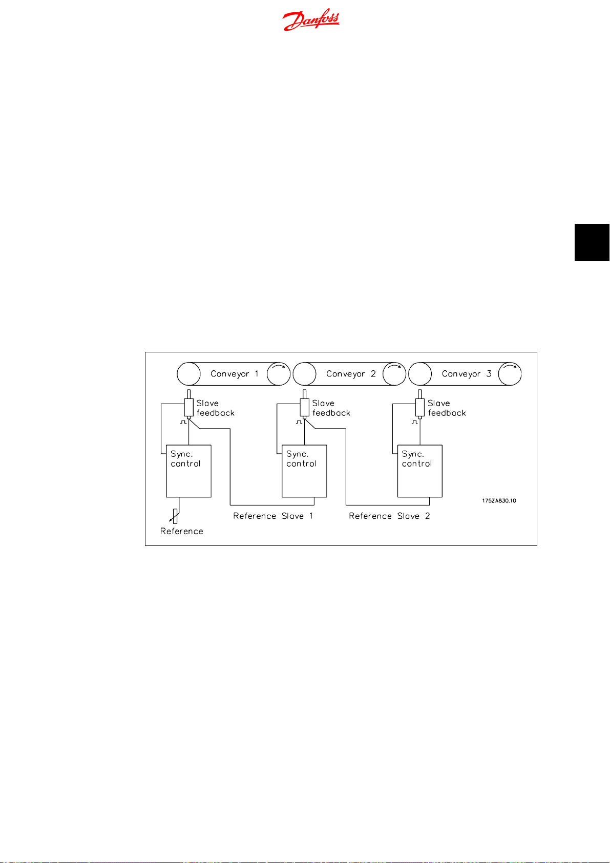
Syncronising Controller MCO 350 Operating
Instructions
Track Error
The synchronising controller of the slave drive uses the master drive signal and the gear ratio to
calculate a reference position value for the slave drive. The deviation of the feedback position
from the calculated position is known as the track error. This is specified in quad counts. The
maximum track error is also a threshold value that defines the permitted operating area of the
synchronising controller.
Accuracy
This value specifies the permitted deviation between the master and slave at which synchronisation is still present.
PPR
Pulses per revolution.
Virtual master
If several axes are to travel in synchrony, or if the synchronisation error is so to be kept as small
as possible, it is often more advantageous not to take the reference position from a drive, but to
have a master that simulates the reference position. This has the advantage that the cycle times
of the individual drives are not added. These differences are illustrated below for the synchronous
control of three conveyor belts. First, we show the classic synchronisation procedure where the
reference value signal is taken from the preceding drive in each case.
5. Appendix
5
Illustration 5.1: Synchronisation without Virtual Master
As can be seen from the diagram below, at Start, as well as with every change in speed of the
master drive, the cycle times are added. They are then compensated for again based on the control
characteristics of the controller in question.
MG.33.Q1.02 - VLT
®
is a registered Danfoss trademark
97

5
5. Appendix
Syncronising Controller MCO 350 Operating
Instructions
Illustration 5.2: Addition of the Cycle Times
In this case, the same application is realised by means of incorporating a virtual master. Although
the way that the reference value is introduced at the first belt is analogous, the value is used to
set the virtual master signals.
Illustration 5.3: Synchronisation with Virtual Master
It can be seen from the diagram below that the cycle time error is not added; instead, one cycle
time applies for all the drives. The advantage of this is that the control has fewer errors to correct.
98
MG.33.Q1.02 - VLT
®
is a registered Danfoss trademark

Syncronising Controller MCO 350 Operating
Instructions
Illustration 5.4: No Addition of the Cycle Times
5. Appendix
5
MG.33.Q1.02 - VLT
®
is a registered Danfoss trademark
99

Index
Syncronising Controller MCO 350 Operating
Instructions
Index
A
Absolute Encoder 96
Acceleration Feed Forward 38
Accuracy 40
Activate Feed Forward 28
Admixture 51
Angle Synchronisation 58
Application Example 62
Approvals 5
B
Band Width Pid Controller 92
Brake Off Delay 12
Brake On Delay 33
C
Calculation 13
Changing The Gear Ratio With An Analogue Value 51
Control Source Synchronising 89
Control Source Test Run 32
Corrected Numerical Values 13
D
Data Layout 23
Delta Hold Speed 28
Denominator 29
Description Of Fieldbus Interface 23
Description Of Parameters 27
Description Of Terminals 51
Digital Inputs: 17
Digital Outputs 17
Direction Of Rotation 36
Disposal Instruction 5
D-portion 37
E
Earth Leakage Current 6
Embossing Patterns On Mould 62
Encoder Monitor 16
Encoder Resolution 53
Encoder Velocity 29
Error Messages 81
Error Procedure 58
Error Reference 81
Example Of Encoder Interface Connections 19
F
Ffvel Calc 28
Fieldbus Control Signals 24
Fieldbus Status Signals 25
Fine Setting Of The Gear Ratio 58
Fine Setting Of The Position 68
Fixed Offset 30
Function Description 11
Function Diagrams For Marker Synchronisation 69
Function Diagrams For Position Synchronisation 60
Function Diagrams For Speed Synchronisation 47
G
Gear Changing 50
100
MG.33.Q1.02 - VLT
®
is a registered Danfoss trademark
 Loading...