

Page 1
Switching between mains supply and VLT
®
Switching between mains supply and VLT® frequency converter by means of a change-over switch
In certain plants, e.g. pump or ventilation plants, the use of the same motor in two different ways may be
expedient:
A) Connected direct to the mains supply so that the motor is running at a fixed speed.
B) Connected to a frequency converter so that the speed of the motor is variable.
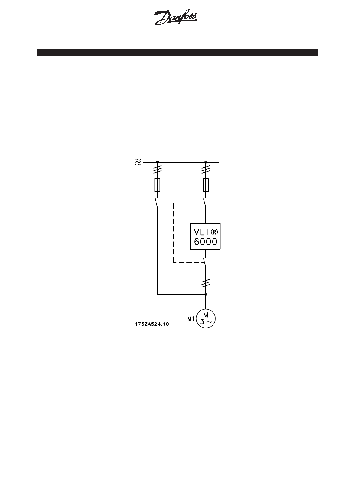
Fig. 1 illustrates how the motor "M1" can be connected either direct to the mains or to a VLT
®
6000
frequency converter:
Switching between mains supply and VLT
®
1MN.60.R1.02 - VLT is a registered Danfoss trademark
Page 2
Switching between mains supply and VLT
®
Switching between mains supply and VLT
Advantages by switching between mains supply and VLT frequency converter by means of change-over
switch
■ The possibility of switching between mains operation and operation via VLT frequency converter can be
used to increase the reliability of the plant through a redundant system
■ Operating on the mains supply, the motor can yield a very high breakaway torque
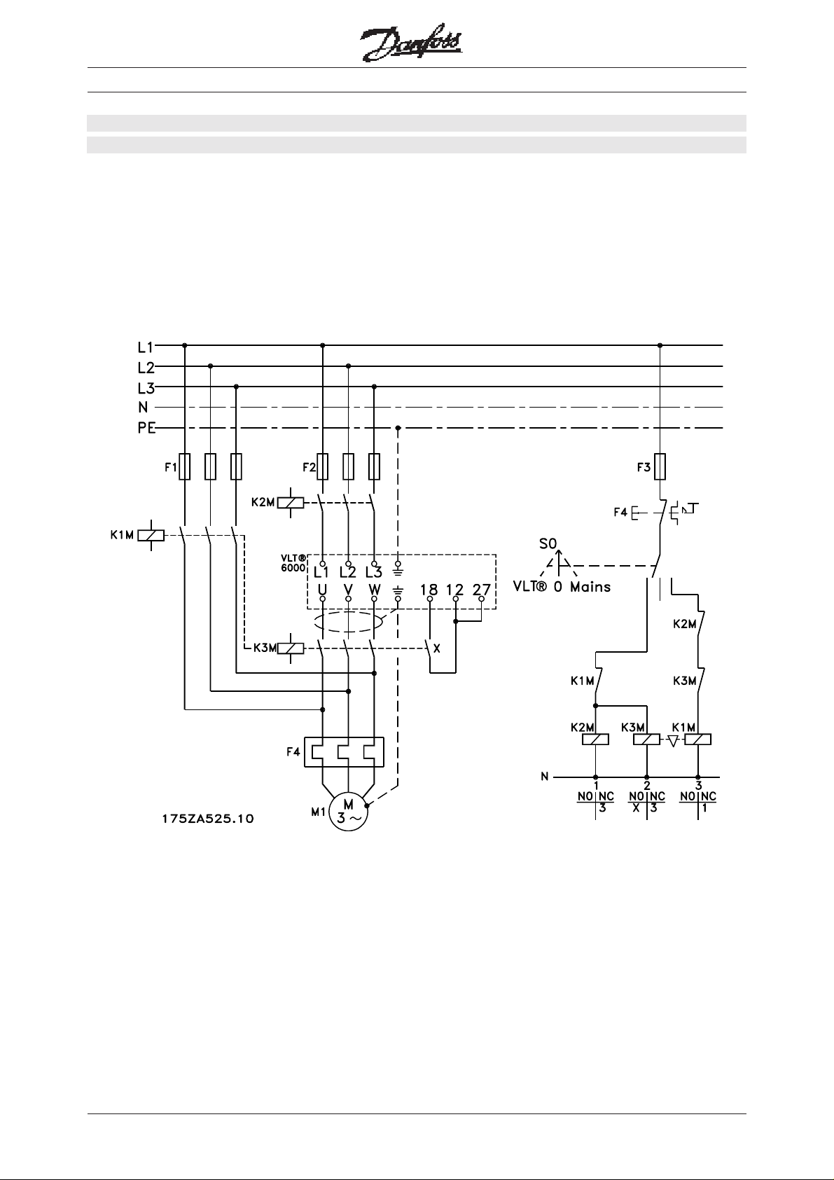
The diagram below shows how the switchgear can be made:
®
2
MN.60.R1.02 - VLT is a registered Danfoss trademark
Page 3

Switching between mains supply and VLT
®
Mains operation
Start:Start:
■
Start: Turn the switch "S0" from position "0" to position "MAINS”. Then the relay
Start:Start:
"K1M” is energized and the motor starts.
Stop:Stop:
■
Stop: Turn the switch "S0" back to position "0". The relay "K1M” drops out and the
Stop:Stop:
motor stops.
Operation via VLT frequency converter
Start:Start:
■
Start: Turn the switch "S0" to position "VLT”. The relays "K2M” and "K3M”
Start:Start:
are energized and the VLT frequency converter will power up and start the motor using
"Flying start”. If the motor may not start, when the drive is powered up, then an additional start
condition must be set, as described in the operating instructions. It is now possible to control the
speed and torque of the motor via the normal control inputs of the frequency converter.
Stop:Stop:
■
Stop: Turn the switch "S0" back to position "0".Then the relays "K2M” and "K3M” fall and the motor
Stop:Stop:
stops.
List of components
Switching between mains supply and VLT
®
F1:F1:
■
F1: 3 motor fuses
F1:F1:
F2:F2:
■
F2: 3 fuses for the VLT frequency converter. Size A = acording to MG60A202
F2:F2:
F3:F3:
■
F3: 1 control current fuse
F3:F3:
F4:F4:
■
F4: Thermal relay with stop, type CI
F4:F4:
K1M:K1M:
■
K1M: Contactor, type CI, with one NC auxiliary contacts
K1M:K1M:
(NC = Normally closed)
K2M:K2M:
■
K2M: Contactor, type CI, with one NC auxiliary contact
K2M:K2M:
K3M:K3M:
■
K3M: Contactor, type CI, with one NC auxiliary contact and a CBNO Code No. 037H0121 (gold plated
K3M:K3M:
NO contact)
(NO = Normally open)
S0:S0:
■
S0: 1-pole change-over switch with 3 positions
S0:S0:
1 mechanical interlock to be placed between "K1M” and "K3M”, to prevent that somebody by hand pushes
down the contacter bridge.
F2 and K2M can be substituded if it is accepted acording to local code of Practicel with a "Circuit Breakers”
type CTI. For further information, see Application notes MN500102.
Further information:
Operating instructions VLT 6000 HVAC Code No. MG.60.AX.YY
Motor Control Gear Code No. IK40T202 and MN.90.KX.YY
X = version number
YY = language version
3MN.60.R1.02 - VLT is a registered Danfoss trademark
 Loading...