


Contents
■
VLT®5000/6000/8000 Series
Introd
Mechanical installation
Electri
uction
General warning ..................................................................................................... 2
Introduction ........................................................................................................... 3
ortation and uncrating ................................................................................ 4
Transp
Key diagram for VLT 5300-5500 / VLT 6350-6550 / VLT 8350-8550 ................... 6
Technical data ........................................................................................................ 7
Mechanical dimensions ......................................................................................... 11
stallation ...................................................................................................... 12
Pre-in
Installation site ....................................................................................................... 12
Cable site .............................................................................................................. 13
g for high altitude ........................................................................................ 13
Deratin
Derating for ambient temperature .......................................................................... 13
cal installation
Electrical installation .............................................................................................. 14
Pre-fuses .............................................................................................................. 14
g ................................................................................................................ 14
Earthin
RFI switch ............................................................................................................. 15
Electrical installation, power cables ........................................................................ 15
cal installation, enclosure .............................................................................. 17
Electri
Terminal adapter kit .............................................................................................. 18
Tightening-up torques ........................................................................................... 18
tion of 24 Volt external DCsupply ............................................................... 18
Installa
Installation of brake resistor temperature switch ................................................... 18
Cable cross-section and length ............................................................................. 19
Mains con
Motor connection .................................................................................................. 21
Brake connection (VLT 5000 Series ONLY) .......................................................... 22
Load shar
Motor and DC coils connections on IP 00 ............................................................. 23
Control cable routing ............................................................................................ 24
Connectio
Electrical installation procedures ........................................................................... 27
Electrical installation, control leads ........................................................................ 28
Programmi
Programming the VLT 6000 and VLT 8000 AQUA ................................................ 28
Motor start ............................................................................................................ 28
....................................................................................................... 2
................................................................................ 11
.................................................................................... 14
nection .................................................................................................. 20
ing connection ...................................................................................... 22
n example ............................................................................................. 25
ng the VLT 5000 .................................................................................. 28
MG.56.A2.02 - VLT is a registered Danfoss trademark
1
VLT®5000/6000/8000 Series
General warning
■
The voltage of the frequency converter
is dangerous whenever the converter is
connected to mains. Incorrect fitting of the
motor or frequency converter may cause damage to the
equipment, serious injury or death. Consequently, it is
essential to comply with the instructions in this manual
as well as local and national rules and safety regulations.
1. The VLT frequency converter must be disconnected
mains if repair work is to be carried out. Check
from
that the mains supply has been disconnected
and that the necessary time has passed before
ving motor and mains plugs.
remo
2. The [STOP/RESET] or [OFF/STOP] key on the
control panel of the VLT frequency converter does
isconnect the equipment from mains and is
n
ot d
thus n
ot to be used as a safety switch.
3. Correct protective earthing of the equipment
t be established, the user must be protected
mus
against supply voltage, and the motor must be
protected against overload in accordance with
licable national and local regulations.
app
4. The earth leakage currents are higher than 3.5 mA.
5. Protection against motor overload is n
he factory setting. If this function is desired, set
in t
parameter 128 to data value ETR trip or data value
ETR warning. On VLT 6000, set parameter 117 to
ta value ETR trip or data value ETR warning.
da
N
ote: The function is initialised at 1.16 x
rated motor current and rated motor frequency
ee Operating manual).
(s
ot included
For the North American market: The ETR
functions provide class 20 motor overload
tion in accordance with NEC.
protec
6. Do n
7. Please note that the VLT frequency converter has
Warning against unintended start
■
1. The m
2. While parameters are being changed, the
3. A motor that has been stopped may start if faults
ot remove the plugs for the motor and
mains supply while the VLT frequency converter
nected to mains. Check that the mains
is con
supply has been disconnected and that the
necessary time has passed before removing
and mains plugs.
motor
more voltage inputs than L1, L2 and L3, when
haring (linking of DC intermediate circuit) and
loads
external 24 V DC have been installed. Check
that all voltage inputs have been disconnected
hat the necessary time has passed before
and t
repair work is commenced.
otor can be brought to a stop by
means of digital commands, bus commands,
references or a local stop, while the frequency
verter is connected to mains. If personal
con
safety considerations make it necessary to
ensure that no unintended start occurs, these
p functions are not sufficient.
sto
motor may start. Consequently, the stop key
OP/RESET] or [OFF/STOP] must always be
[ST
activated, following which data can be modified.
cur in the electronics of the frequency converter,
oc
or if a temporary overload or a fault in the supply
mains or the motor connection ceases.
176FA055.11
Warning:
Touching the electrical parts may be fatal - even after the
equipment has been disconnected from mains.
Also make sure that other voltage inputs have been disconnected,
such as external 24 V DC, load-sharing (linkage of DC intermediate
circuit), as well as the motor connection for kinetic back-up.
Using VLT 5300-5500 / 6350-6550 /8350-8550:
wait at least 15 minutes
2
MG.56.A2.02 - VLT is a registered Danfoss trademark

Introduction
■
Manual objectives
The pur
with the necessary information to install, program and
start up the Danfoss VLT 5300-5500, VLT 6350-6550
and VL
manual should be read thoroughly before operating,
servicing or initializing the drives. This manual is
inten
Instructions Manual for the VLT 5000/6000/8000
frequency converters for detailed information.
pose of this manual is to provide the user
T 8350-8550 frequency converters. This
ded for use along with the Danfoss Operating
VLT®5000/6000/8000 Series
Who should use this manual
This manual is intended for qualified service
personnel responsible for setting up and servicing
the Danfoss VLT 5300-5500, VLT 6350-6550 and
VLT 8350-8550 frequency converters. Qualified
personnel have previous experience with the
frequency converters and understand electrical
fundamentals, programming procedures, required
equipment and safety precautions.
Organization of the manual
This manual is arranged in equipment installation
connection sequence. The order of tasks
and
are arranged as follows:
•
Safety instructions
•
nsportation and unpacking
Tra
•
Technical data
•
Mechanical installation
•
-installation
Pre
•
Electrical installation guidelines
•
Control cable routing
•
•
•
ection examples
Conn
Electrical installation procedures
Motor start
Introduction
MG.56.A2.02 - VLT is a registered Danfoss trademark
3
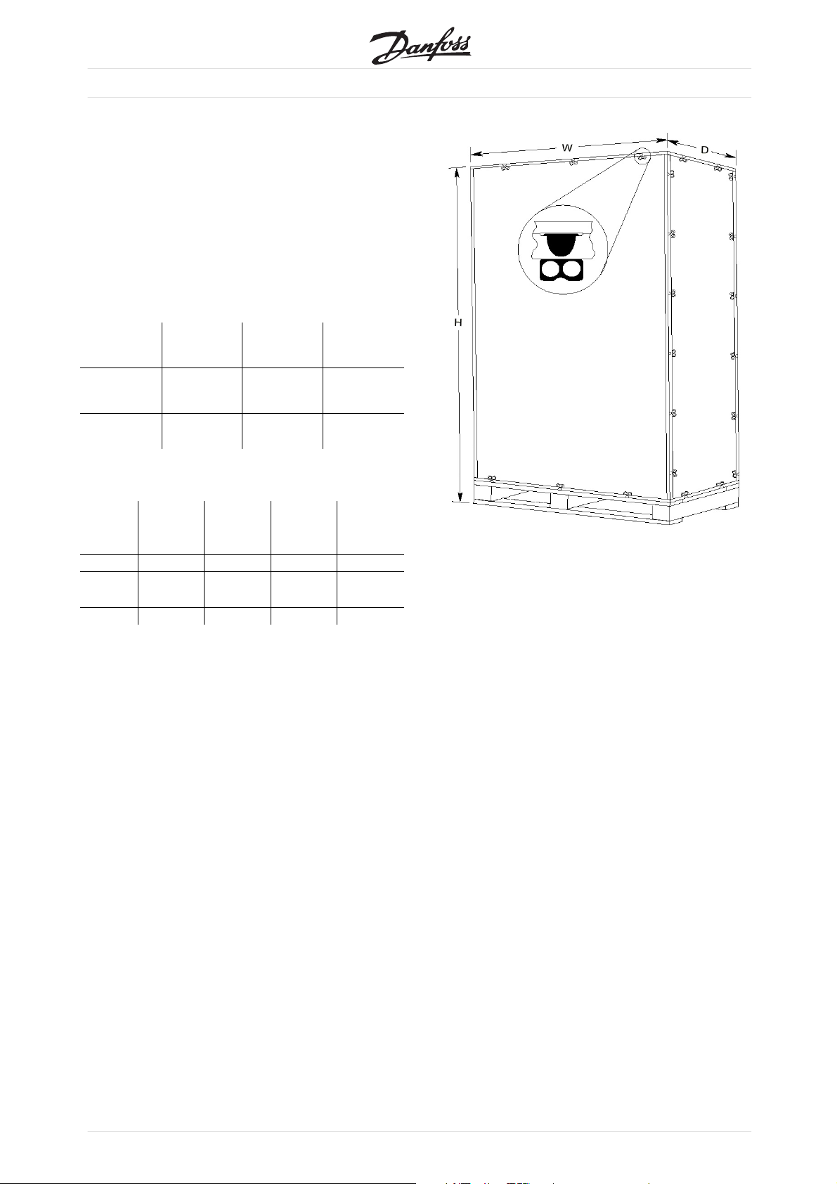
Transportation and uncrating
■
To lessen the possibility of damage it is recommended
e crated VLT frequency converter is
that th
located as close to the final installation site
as possible before uncrating.
Door and ceiling clearances must be considered when
moving and installing the VLT frequency converter.
Seebelowtableforthecratedimensions:
Dimensions mm (inches):
H W D
VLT®5000/6000/8000 Series
IP 00 2096
(82.52)
Nema 1 (IP
20) / 54
2324
(91.5)
1219
(48.0)
1321
(52.0)
699
(27.52)
724
(28.5)
Weight kg (lbs):
VLT
5300/6350/
8350/8550
IP 00 548 (1208) 583 (1385) 628 (1385) 653 (1440)
Nema 1
(IP 20)
IP 54 664 (1464) 699 (1541) 744 (1640) 769 (1695)
654 (1442) 689 (1519) 734 (1618) 759 (1673)
VLT
5350/6400/
8350/8550
VLT
5450/6500/
8350/8550
VLT
5500/6550/
8350/8550
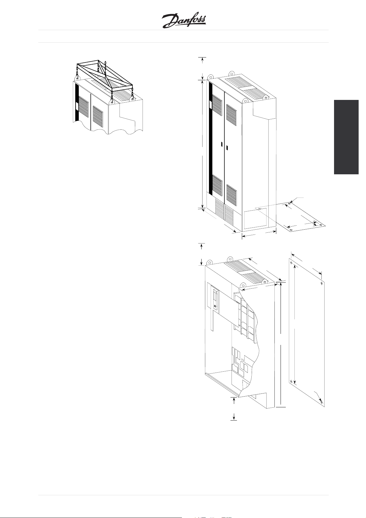
A qualified person with a forklift or other similar
lifting device will be needed to remove the VLT
frequency converter from the crate.
To open the crate:
•
Remove the metal locking tabs that secure the top
panel of the crate, this will give access to the lifting
rings on the top of the VLT frequency converter.
•
On IP 00 versions remove the supporting
brace bolted to the lifting rings.
•
A forklift or similar lifting device should be
used at this time to ensure the stability of the
VLT frequency converter while the rest of the
crate is removed. Position the lifting device
to the front side of the crate.
•
The VLT frequency converter should be lifted using
a spreader bar or other similar lifting device. Lift the
LT frequency converter slightly, using all four lifting
V
rings, distributing the weight as evenly as possible.
4
MG.56.A2.02 - VLT is a registered Danfoss trademark
•
Remove the metal locking tabs and the
remaining crate panels.
•
On IP 00 versions remove the clear plastic safety
ier from the front of the unit to prevent
barr
the possibility of breaking during positioning
of the VLT frequency converter.
•
The VLT frequency converter is now ready to
be lifted and positioned in the installation site.
NOTE: On IP 00 versions there are inductors
bolted to the bottom of the crate. Lift the
VLT frequency converter high enough to allow
clearance over these inductors.
VLT®5000/6000/8000 Series
Min. free air space
above the drive
15.7
(400)
79.1
(2010)
47.2
Min. free air space
15.7
above the drive
(400)
(1200)
23.6
(600)
43.3
(1099)
Mounting holes in
bottom panel
4 x ø0.63
(16)
42.3
(1075)
18.7
(475)
41.9
(1065)
Introduction
•
erve cooling and ventilation requirements given
Obs
in the "Installation Site" section of this manual.
•
Secure to the floor using the four holes provided
in the bottom of the unit. On IP 00 versions
secure to the panel using the four mounting holes
provided in the back. Refer to the dimensional
drawings in this instruction manual.
Min. free air space
below the drive
15.7
(400)
19.3
(490)
74.6
(1896)
Mounting holes
in back panel
72.7
(1847)
4 x ø0.63
(16)
MG.56.A2.02 - VLT is a registered Danfoss trademark
5
VLT®5000/6000/8000 Series
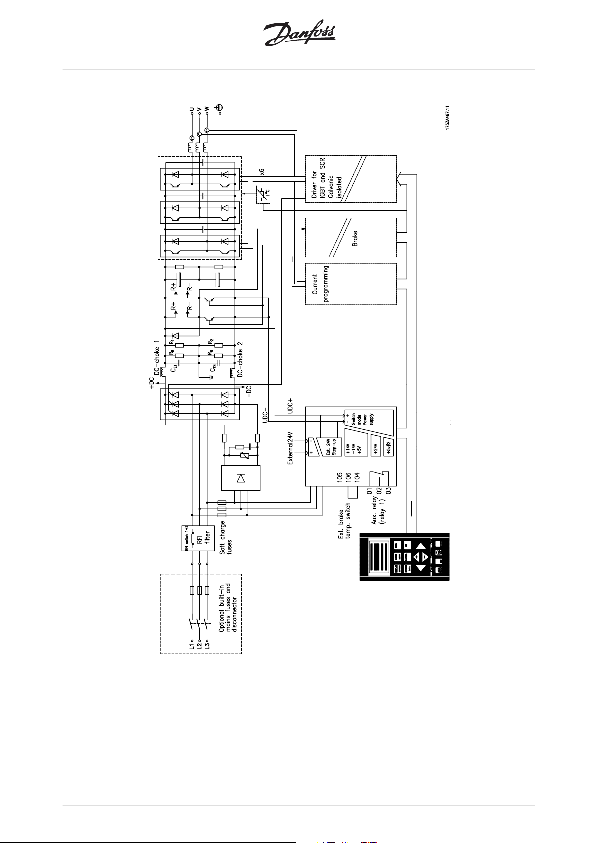
Key diagram for VLT 5300-5500 / VLT 6350-6550 / VLT 8350-8550
■
Brake terminals 81, 82 and 104-106 are not
available in VLT 6000 HVAC.
6
MG.56.A2.02 - VLT is a registered Danfoss trademark
VLT®5000/6000/8000 Series
Compact, Mains supply 3 x 380 - 500 V
■
According to international requirements VLT type 5300 5350 5450 5500
Normal overload torque (110 %):
Output current I
I
VLT, MAX
I
VLT, MAX
Output S
S
Typical shaft output (380-440 V) P
Typical shaft output (380-440 V) P
Typical shaft output (441-500 V) P
Typical shaft output (441-500 V) P
High overload torque (150 %):
Output current I
I
VLT, MAX
I
VLT, MAX
Output S
S
Typical shaft output (380-440 V) P
Typical shaft output (380-440 V) P
Typical shaft output (441-500 V) P
Typical shaft output (441-500 V) P
Max. cross-section of copper cable to motor, brake 2x150 2x185 2x240 2x300
and loadsharing (380-440 V) [mm
Max. cross-section of copper cable to motor, brake 2x120 2x150 2x185 2x300
and loadsharing (441-500 V) [mm
Max. cross-section of aluminium cable to motor, brake 2x185 2x240 2x300
and loadsharing (380-440 V) [mm
Max. cross-section of aluminium cable to motor, brake 2x150 2x185 2x240
and loadsharing (441-500) [mm
2]5)
Max. cross-section of copper cable to motor, brake 2x250mcm 2x350mcm 2x400mcm 2x500mcm
and loadsharing (380-440 V) AWG]
Max. cross-section of copper cable to motor, brake 2x4/0 2x300mcm 2x350mcm 2x500mxm
and loadsharing (441-500 V) AWG]
Max. cross-section of aluminium cable to motor, brake 2x350mcm 2x500mcm 2x600mcm 2x700mcm
and loadsharing (380-440 V) AWG]
Max. cross-section of aluminium cable to motor, brake 2x300mcm 2x400mcm 2x500mcm 2x600mcm
and loadsharing (441-500 V) AWG]
[A] (380-440 V) 480 600 658 745
VLT,N
(60 s) [A] (380-440 V) 528 660 724 820
I
[A] (441-500 V) 443 540 590 678
VLT,N
(60 s) [A] (441-500 V) 487 594 649 746
[kVA] (380-440 V) 333 416 456 516
VLT,N
[kVA] (441-500 V) 384 468 511 587
VLT,N
[kW] 250 315 355 400
VLT,N
[HP] 300 350 450 500
VLT,N
[kW] 315 355 400 500
VLT,N
[HP] 350 450 500 600
VLT,N
[A] (380-440 V) 395 480 600 658
VLT,N
(60 s) [A] (380-440 V) 593 720 900 987
I
[A] (441-500 V) 361 443 540 590
VLT,N
(60 s) [A] (441-500 V) 542 665 810 885
[kVA] (380-440 V) 274 333 416 456
VLT,N
[kVA] (441-500 V) 313 384 468 511
VLT,N
[kW] 200 250 315 355
VLT,N
[HP] 300 350 450 500
VLT,N
[kW] 250 315 355 400
VLT,N
[HP] 350 450 500 600
VLT,N
2]5)
2]5)
2]5)
3x70 3x95 3x120 3x150
3x70 3x95 3x95 3x120
3x120 3x150 3x185 3x185
3x95 3x120 3x150 3x185
2) 5)
2) 5)
2) 5)
2) 5)
3x2/0 3x3/0 3x4/0 3x250mcm
31/0 3x3/0 3x3/0 3x4/0
3x4/0 3x250mcm 3x300mcm 3x350mcm
3x3/0 3x4/0 3x250mcm 3x300mcm
Introduction
1. For type of
fuse see section Fuses.
2. American Wire Gauge.
3. Measured using 30 m screened motor cables at rated load and rated frequency.
4. Min. cable
cross-section is the smallest cable cross-section allowed to be fitted on the terminals. Always
comply with national and local regulations on min. cable cross-section.
5. Connection stud 2 x M12/3 x M12.
MG.56.A2.02 - VLT is a registered Danfoss trademark
7
VLT®5000/6000/8000 Series
Compact, Mains supply 3 x 380 - 500 V
■
According to international requirements VLT type 5300 5350 5450 5500
Rated input current
110%
Rated input current
150%
Max. cross-section of copper cable 2x150 2x185 2x240 2x300
to power (380-440 V) [mm
Max. cross-section of copper cable 2x120 2x150 2x185 2x300
to power (441-500 V) [mm
Max. cross-section of aluminium cable 2x185 2x240 2x300
to power (380-440 V) [mm
Max. cross-section of aluminium cable 2x150 2x185 2x240
to power (441-500 V) [mm
Max. cross-section of copper cable 2x250mcm 2x350mcm 2x400mcm 2x500mcm
to power (380-440 V) [AWG]
Max. cross-section of copper cable 2x4/0 2x300mcm 2x350mcm 2x500mcm
to power (441-500 V) [AWG]
Max. cross-section of aluminium cable 2x350mcm 2x500mcm 2x600mcm 2x700mcm
to power (380-440 V) [AWG]
Max. cross-section of aluminium cable 2x300mcm 2x400mcm 2x500mcm 2x600mcm
to power (441-500 V) [AWG]
Max. pre-fuses (mains) [-]/UL1)[A] 630/600 700/700 800/800 800/800
Integral pre-fuses (softcharge circuit)
6)
[-]/UL
[A]
Integral pre-fuses (snubber resistors)
7)
[-]/UL
Integral
[A]
pre-fuses (SMPS) [-]/UL
Efficiency 0.97 0.97 0.97 0.97
Weight IP
00
Weight Nema 1 kg (lb) 595 (1132) 630 (1389) 675 (1488) 700 (1543)
Weight IP 5
4
Power loss at max. load [W] 7500 9450 10650 12000
Enclosure IP 00 / Nema
I
[A] (400 V) 467 584 648 734
L,MAX
[A] (460 V)
I
L,MAX
I
[A] (400 V) 389 467 584 648
L,MAX
I
[A] (460 V) 356 431 526 581
L,MAX
2]5)
2]5)
2]5)
2]5)
2) 5)
2) 5)
2) 5)
2) 5)
431 526 581 668
3x70 3x95 3x120 3x150
3x70 3x95 3x95 3x120
3x120 3x150 3x185 3x185
3x95 3x120 3x150 3x185
3x2/0 3x3/0 3x4/0 3x250mcm
31/0 3x3/0 3x3/0 3x4/0
3x4/0 3x250mcm 3x300mcm 3x350mcm
3x3/0 3x4/0 3x250mcm 3x300mcm
9/9 9/9 9/9 9/9
15/15 15/15 15/15 15/15
8)
[A]
5.0/5.0 5.0/5.0 5.0/5.0 5.0/5.0
kg (lb) 480 (1058)515 (1135)560 (1235)585 (1290
kg (lb) 605 (1334) 640 (1411) 685 (1510) 710 (1565)
1 (IP 20) / IP 54
)
1. For type of fuse see section Fuses.
2. American Wire Gauge.
3. Measure
d using 30 m screened motor cables at rated load and rated frequency.
4. Min. cable cross-section is the smallest cable cross-section allowed to be fitted on the terminals. Always
comply with national and local regulations on min. cable cross-section.
5. Connect
ion stud 2 x M12/3 x M12.
6. If UL/cUL is to be complied with, AC Littelfuse type KLK, Danfoss ordering no. 175L3489 must be used.
7. If UL/cUL is to be complied with, DC Littelfuse type KLKD, Danfoss ordering no. 176F1147 must be
used.
8. If UL/cUL is to be complied with, Bussmann type KTK-5, Danfoss ordering no. 175L3437 must be used.
8
MG.56.A2.02 - VLT is a registered Danfoss trademark
VLT®5000/6000/8000 Series
Mains supply 3 x 380-500 V
■
ing to international
Accord
requirements VLT type 6350 6450 6500 6550
8350 8450 8500 8550
Output
current
I
VLT, MAX
I
VLT, MAX
Output S
S
VLT,N
VLT,N
Typical shaft output (380-415 V) P
Typical shaft output (380-415 V) P
Typical shaft output (440-460 V) P
Typical shaft output (440-460 V) P
[A] (380-415 V)
I
VLT,N
480 600 658 745
(60 s)[A](380-415 V) 528 660 724 820
I
[A] (440-460 V) 443 540 590 678
VLT,N
(60 s)[A](440-460 V) 487 594 649 746
[kVA] (380-415 V) 333 416 456 516
kVA] (440-460 V)
[
[kW] 250 315 355 400
VLT,N
[HP] 300 350 450 500
VLT,N
[kW] 315 355 400 500
VLT,N
[HP] 350 450 500 600
VLT,N
384 468 511 587
Max. cross-section of copper cable to motor, 2 x 150 2 x 185 2 x 240 2 x 300
brake and
loadsharing (380-415 V) [mm
2]5)
3x70 3x95 3x120 3x150
Max. cross-section of copper cable to motor 2 x 120 2 x 150 2 x 185 2 x 300
and loadsharing (440-460 V) [mm
2]5)
Max. cross-section of aluminium cable to
motor and loadsharing (380-415 V) [mm
2]5)
Max. cross-section of aluminium cable to
motor and loadsharing (440-460) [mm
2]5)
Max. cross-section of copper cable to motor
and loadsharing (380-415 V) AWG]
2) 5)
Max. cross-section of copper cable to motor
and loadsharing (440-460 V) AWG]
2) 5)
Max. cross-section of aluminium cable to
motor and loadsharing (380-415 V) AWG]
2) 5)
Max. cross-section of aluminium cable to
motor and loadsharing (440-460 V) AWG]
2) 5)
3 x 70 3 x 95 3 x 95 3 x 120
2 x 185 2 x 240 2 x 300
3 x 120 3 x 150 3 x 185 3 x 185
2 x 150 2 x 185 2 x 240
3 x 95 3 x 120 3 x 150 3 x 185
2x250mcm 2x350mcm 2x400mcm 2x500mcm
3 x 2/0 3 x3/0 3 x 4/0 3x250mcm
2 x 4/0 2x300mcm 2x350mcm 2x500mcm
3 x 1/0 3 x 3/0 3 x 3/0 3 x 4/0
2x350mcm 2x500mcm 2x600mcm 2x700mcm
3 x 4/0 3x250mcm 3x300mcm 3x350mcm
2x300mcm 2x400mcm 2x500mcm 2x600mcm
3 x 3/0 3 x 4/0 3x250mcm 3x300mcm
Introduction
1. For type of fuse see section Fuses.
2. American Wire Gauge.
3. Measured using 30 m screened motor cables
atratedloadandratedfrequency.
4. Min. cable cross-section is the smallest cable
cross-section allowed to be fitted on the terminals.
Always comply with national and local regulations
on min. cable cross-section.
5. Connection stud 2 x M12/3 x M12.
6. If UL/cUL is to be complied with, AC
Littelfuse type KLK, Danfoss ordering no.
175L3489 must be used.
7. If UL/cUL is to be complied with, DC
Littelfuse type KLKD, Danfoss ordering no.
176F1147 must be used.
MG.56.A2.02 - VLT is a registered Danfoss trademark
8. If UL/cUL is to be complied with, Bussmann type
KTK-5, Danfoss ordering no. 175L3437
must be used.
9

According to international
ements
requir
Rated input
current
Max. cross-section of copper cable to power
(380-415 V) [mm
2]5)
Max. cross-section of copper cable to power
(440-460 V) [mm2]
5)
Max. cross-section of aluminium cable to
power (380-415 V) [mm2]
5)
Max. cross-section of aluminium cable to
power (440-460 V) [mm
2]5)
Max. cross-section of copper cable to power
(380-415 V) AWG]
2) 5)
Max. cross-section of copper cable to power
(440-460 V) AWG]
2) 5)
Max. cross-section of aluminium cable to
power (380-415 V) AWG]
2) 5)
Max. cross-section of aluminium cable to
power (440-460 V) AWG]
2) 5)
Max. pre-fuses (mains)[-]/UL1)[A] 630/600 700/700 800/800 800/800
Integral pre-fuses (softcharge circuit)[-]/UL6)[A] 9/9 9/9 9/9 9/9
Integral p
re-fuses (snubber resistors)[-]/UL
Integral pre-fuses (SMPS) 5.0/5.0
Efficiency 0.97
Weight IP 00 kg (lb)
Weight Nema 1 (IP 20) kg (lb)
Weight IP 54 kg (lb)
Power loss a
tmax. load[W]
Enclosure IP 00 / Nema 1 (IP 20) / IP 54
1. For t
ype of fuse see section Fuses.
2. American Wire Gauge.
3. Measured using 30 m screened motor cables
tedloadandratedfrequency.
at ra
4. Min. cable cross-section is the smallest cable
cross-section allowed to be fitted on the terminals.
ys comply with national and local regulations
Alwa
on min. cable cross-section.
5. Connection stud 2 x M12/3 x M12.
6. If UL
/cUL is to be complied with, AC
Littelfuse type KLK, Danfoss ordering no.
175L3489 must be used.
7. If UL
/cUL is to be complied with, DC
Littelfuse type KLKD, Danfoss ordering no.
176F1147 must be used.
VLT®5000/6000/8000 Series
VLT type6350 6450 6500 6550
8350 8450 8500 8550
I
[A] (400 V) 467 584 648 734
L,N
I
(460 V) 431 526 581 668
L, N
2 x 150 2 x 185 2 x 240 2 x 300
3x70 3x95 3x120 3x150
2 x 120 2 x 150 2 x 185 2 x 300
3 x 70 3 x 95 3 x 95 3 x 120
2 x 185 2 x 240 2 x 300
3 x 120 3 x 150 3 x 185 3 x 185
2 x 150 2 x 185 2 x 240
3 x 95 3 x 120 3 x 150 3 x 185
2x250mcm 2x350mcm 2x400mcm 2x500mcm
3 x 2/0 3 x3/0 3 x 4/0 3x250mcm
2 x 4/0 2x300mcm 2x350mcm 2x500mcm
3 x 1/0 3 x 3/0 3 x 3/0 3 x 4/0
2x350mcm 2x500mcm 2x600mcm 2x700mcm
3 x 4/0 3x250mcm 3x300mcm 3x350mcm
2x300mcm 2x400mcm 2x500mcm 2x600mcm
3 x 3/0 3 x 4/0 3x250mcm 3x300mcm
7)
[A]
15/15 15/15 15/15 15/15
480
(1058)
595
(1132)
605
(1334)
7500 9450 10650 12000
8. If UL
/cUL is to be complied with, Bussmann type
KTK-5, Danfoss ordering no. 175L3437
must be used.
515
(1135)
630
(1389)
640
(1411)
560
(1235)
675
(1488)
685
(1510)
585
(1290)
700
(1543)
710
(1565)
10
MG.56.A2.02 - VLT is a registered Danfoss trademark

VLT®5000/6000/8000 Series
Mechanical installation
■
Mechanical dimensions
■
VLT 5300-5500 380-500 Volt, VLT 6350-6550 380-460 Volt and VLT 8350-8550 380-480 Volt
VLT type A mm (in) B mm (in) C mm (in) ab mm (in) l/r mm (in)
5300-5500/6350-6550/
8350-8550 IP 00
5300-5500/6350-6550/
8350-8550 Nema 1 (IP 20)
5300-5500/6350-6550/
8350-8550 IP 54
ab: Min. space above enclosure.
l/r: Min. distance between VLT frequency converter
and other plant components, left and right sides.
1896 (74.65) 1099 (43.27) 494 (19.45) 400 (15.75) 0
2010 (79.13) 1200 (47.24) 600 (23.62) 400 (15.75) 0
2010 (79.13) 1200 (47.24) 600 (23.62) 400 (15.75) 0
VLT 5300-5500, VLT 6350-6550 and VLT 8350-8550
must be fastened to the floor with bolts. The
drawing shows the dimensions.
Mechanical installation
MG.56.A2.02 - VLT is a registered Danfoss trademark
11

Pre-installation
■
The most important part of the mechanical
-lation is the pre-installation planning. Neglecting
instal
this planning may very well result in extra work
during and after the installation
Before you install your VLT frequency converter you
should select the best possible operational site.
Consider the following in the pre-installation plan:
•
Ambient operating temperature.
•
Installation method.
•
The position of the VLT frequency converter.
•
The cable routing.
•
Ensure that the power source supplies the
correct voltage and necessary current.
•
If the VLT frequency converter is without
built-in mains disconnector and fuses, ensure
that the external disconnector or fuses have
the correct current rating.
VLT®5000/6000/8000 Series
Installation site
■
The VLT
installed vertically.
The VLT frequency converter is cooled by means of
air circulation. For the unit to be able to release its
cooling air, the minimum distance over the unit must
be as shown in the table under Mechanical Dimension.
To protect the unit from overheating, it must be
ensured that the ambient temperature does not rise
above the max. temperature stated for the VLT
frequency converter and that the 24-hour average
temperature is not exceeded. The max. tempe-rature
and 24-hour average can be seen from the General
Technical Data in the Operating Instructions.
If the ambient temperature is in the range of
45
converter will become relevant, see Derating
for ambient temperature.
The service life of the VLT frequency converter will
be reduced if derating for ambient temperature
is not taken into account.
frequency converter must be
-55 C, derating of the VLT frequency
Installation of VLT 5300-5500 380-500 V, VLT 6350-6550 380-460 V and VLT 8350-8550
■
380-480 Volt Nema 1 (IP 20) and IP 54
Cooling
Side-by-side
All units in the above-mentioned series require a
minimum space of 400 mm (15.75 in) above the
enclosure and must be installed on a plane floor. This
applies to both Nema 1 (IP 20) and IP 54 units.
Nema 1 (IP 20) and IP 54
All Nema 1 (IP 20) and IP 54 units in the
above-mentioned series can be installed side by
side without any space between them, since these
units do not require cooling on the sides.
12
MG.56.A2.02 - VLT is a registered Danfoss trademark

VLT®5000/6000/8000 Series
Cable site
■
The drawing and table show the mechanical setup
of the cable which can be done before the VLT
frequency converter is installed.
VLT type Mains terminal
VLT 5300-5500/6350-6550/8350-8550 969 mm (38.15 in)
VLT 5300-5500/6350-6550/8350-8550 with RFI 516 mm (20.31 in)
VLT 5300/6350/8350 with RFI/Disconnector 626 mm (24.65 in)
VLT 5350-5500/6400-6550/8350-8550 with RFI/Disconnector 516 mm (20.31 in)
Derating for high altitude
■
Below 1000 m altitude no derating is necessary for
VLT 5300-5500, VLT 6350-6550 or VLT 8350-8550.
Derating for ambient temperature
■
The ambient temperature (T
AMB,MAX
temperature allowed. The average (T
) is the maximum
AMB,AVG
measured over 24 hours must be at least 5ºC lower.
Above 1000 m the ambient temperature (T
max. output current (I
) must be derated in
VLT,MAX
accordance with the diagram below:
AMB
)or
If VLT 5300-5500, VLT 6350-6550 or VLT 8350-8550
is operated at temperatures above 45 ºC, a derating
of the continuous output current is necessary.
1. Derating of output current versus altitude
at T
2. Derating of max. T
= max. 45 C
AMB
versus altitude at
AMB
100% output current.
Mechanical installation
)
MG.56.A2.02 - VLT is a registered Danfoss trademark
13

Electrical installation
■
The voltage on the frequency converter
is dangerous when the unit is
connected to mains.
Incorrect installation of the motor or VLT
frequency converter may lead to material damage
or serious injury or it may be fatal.
quently, the instructions in this manual
Conse
as well as national and local rules and safety
regulations must be complied with.
ing the electrical parts may be fatal, even
Touch
after the mains supply has been disconnected.
Pre-fuses
■
For VLT type 5300-5500, VLT type 6350-6550
and VLT 8350-8550, external pre-fuses must be
VLT®5000/6000/8000 Series
Wait at least 15 minutes if using VLT 5300-5500,
VLT 6350-6550 or VLT 8350-8550.
NB!:
It is the user’s or certified electrician’s
responsibility to ensure correct earthing and
protection in accordance with applicable
national and local norms and standards.
rminals for the control cables and power cables
All te
are located behind the protective cover of the VLT
frequency converter. The protective cover can be
ved by means of a screwdriver.
remo
Once the protective cover has been removed, the
actual EMC-correct installation can start.
installed in the mains supply to the VLT frequency
converter or ordered with built-in pre-fuses and
a mains disconnect switch.
UL compliance
To comply with UL/cUL approvals, pre-fuses according to the table below must be used.
Bussmann SIBA Littel fuse Ferraz-Shawmut
5300/6350/8350 FWH-600 206xx32-600 L50S-600 A50-P600
5350/6450/8450 FWH-700 206xx32-700 L50S-700 A50-P700
5450/6500/8500 FWH-800 206xx32-800 L50S-800 A50-P800
5500/6550/8550 FWH-800 206xx32-800 L50S-800 A50-P800
Non UL compliance
If UL/cUL is not to be complied with, we recommend
the above mentioned fuses or type gR.
Not following the recommendation may result
in unnecessary damage of the drive in case of
malfunction. Fuses must be designed for protection
in a circuit capable of supplying a maximum of
Earthing
■
The following basic issues need to be considered
when installing a frequency converter, so as to
obtain electromagnetic compatibility (EMC).
•
Safety earthing: Please note that the frequency
converter has a high leakage current and must
be earthed appropriately for safety reasons.
Apply local safety regulations.
•
High-frequency earthing: Keep the earth wire
connections as short as possible.
Connect the different earth systems at the lowest
100000 A
The metal cabinets of the different devices are
mounted on the cabinet rear plate using the lowest
possible HF impedance. This avoids having different
HF voltages for the individual devices and avoids the
risk of radio interference currents running in connection
cables that may be used between the devices. The
radio interference will have been reduced.
In order to obtain a low HF impedance, use the
fastening bolts of the devices as HF connection to
the rear plate. It is necessary to remove insulating
paint or similar from the fastening points.
(symmetrical), 500 V maximum.
rms
possible conductor impedance. The lowest possible
conductor impedance is obtained by keeping
the conductor as short as possible and by using
the greatest possible surface area.
14
MG.56.A2.02 - VLT is a registered Danfoss trademark

VLT®5000/6000/8000 Series
RFI switch
■
ains supply isolated from earth:
M
If the V
isolated mains source (IT mains), the RFI switch
can be turned off (OFF). In OFF position, the
intern
the chassis and the intermediate circuit are cut off
to avoid damage to the intermediate circuit and
to red
to IEC 1800-3). See position of RFI switch by
Electrical installation, enclosures.
before operating the RFI switch.
LT frequency converter is supplied from an
al RFI capacities (filter capacitors) between
uce the earth capacity currents (according
NB!:
The RFI switch is not to be operated with
mains connected to the unit. Check that
the mains supply has been disconnected
NB!:
Open RFI switch is only allowed at factory
set swi
NB!:
The RFI switch disconnects the capacitors
galvanically; however, transients higher
than a
by a spark gap.
M
ains supply connected to earth:
The RFI switch must be in ON position in order for the
frequency converter to comply with the EMC-standard.
Electrical installation, power cables
■
tching frequencies.
pprox. 1,000 V will be bypassed
Compact Nema 1 (IP 20)/IP 54
Without disconnector and mains fuses
Electrical installation
VLT 5300-5500
VLT 6350-6550
VLT 8350-8550
MG.56.A2.02 - VLT is a registered Danfoss trademark
15

VLT®5000/6000/8000 Series
Compact Nema 1 (IP 20)/IP 54
With disconnector and mains fuses
VLT 5300-5500
VLT 6350-6550
VLT 8350-8550
Brake terminals 81, 82 and 104-106 are not
available in VLT 6000 HVAC.
16
MG.56.A2.02 - VLT is a registered Danfoss trademark

Electrical installation, enclosure
■
VLT®5000/6000/8000 Series
Compact Nema 1 (IP 20) / IP 54
VLT 5300-5500
VLT 6350-6550
VLT 8350-8550
Brake terminals 81, 82 and 104-106 are not
available in VLT 6000 HVAC.
Electrical installation
MG.56.A2.02 - VLT is a registered Danfoss trademark
17

Terminal adapter kit
■
VLT®5000/6000/8000 Series
VLT type Tightening-up
torque
VLT 5300-5500
1)
42 Nm
(31 lb-ft)
VLT 6350-6550 42 Nm
(31 lb-f
t)
VLT 8350-8550 42 Nm
(31 lb-ft)
1)
For the brake terminals, the tightening-up torque
is 11.3 (8.33 lb-ft) Nm and the bolt size M8.
Bolt
size
M12
M12
M12
The terminal adapter kit is an optional kit for VLT
5300-5500, VLT 6350-6650 and VLT 8350-8550.
The terminal adapter kit makes it possible to connect
the power wires with the power terminals i.e. the
mains-, motor-, load sharing and brake terminals.
The ordering numbers of the terminal adapter kit are:
VLT 5300-5500/6350-6550 EX, DX 176F1815
VLT 5300-5500 EB, DE 176F1816
VLT 8350-8550 EX, DX 175F1815
Tightening-up torques
■
The table shows the torque required when fitting
terminals to the VLT frequency converter.
For VLT 5300-5500, VLT 6350-6550 and VLT
8350-8550 the cables must be fastened with
bolts or the terminal adapter kit. These figures
apply to the following terminals:
Mains terminals Nos R, L1, 91
S, L2, 92
T, L3, 93
Motor terminals Nos U, T1, 96
V, T2, 97
W, T3, 98
Earth terminal No 95
Brake resistor R- 81
terminals R+ 82
Loadsharing DC- 88
DC+ 89
Installation of 24 Volt external DCsupply
■
Torque: 0.5 - 0.6 Nm
Screw size: M3
No. Function
35, 36 24 V external DC supply
24 V external DC supply can be used as low-voltage
supply to the control card and any option cards
installed. This enables full operation of the LCP
(incl. parameter setting) without connection to mains.
Please note that a warning of low voltage will be
given when 24 V DC has been connected; however,
there will be no tripping. If 24 V external DC supply
is connected or switched on at the same time as
the mains supply, a time of min. 200 msec. must
be set in parameter 120 Start delay.
A pre-fuse of min. 6 Amp, slow-blow, can be
fitted to protect the external 24 V DC supply.
The power consumption is 15-50 W, depending
on the load on the control card.
NB!:
Use 24 V DC supply of type PELV to ensure
correct galvanic isolation (type PELV) on the
control terminals of the VLT frequency converter.
Installation of brake resistor temperature switch
■
Torque: 0.5-0.6 Nm
Screw size: M3
No. Function
106, 104,
Brake resistor temperature switch.
105
18
MG.56.A2.02 - VLT is a registered Danfoss trademark

NB!:
This function is only available on VLT
5300-5
If the temperature of the brake resistor
gets too high and the KLIXON switch drops out,
the VLT
The motor will start coasting.
A KLIXON switch must be installed that can either be
lly closed’or normally open’. Ifthisfunctionisnot
norma
used, 106 and 104 must be short-circuited together.
Cable cross-section and length
■
See Technical data for correct sizing of motor
cable and mains cable cross-section. Always
comply with national and local regulations on cable
cross-sections. It is important to keep the motor
cableasshortaspossiblesoastoreducethenoise
level and leakage currents to a minimum.
Max. motor cable length for screened cable
is 150 m (500 ft.).
Max. motor cable length for unscreened
cable is 300 m (1000 ft.).
500 units.
frequency converter will stop braking.
VLT®5000/6000/8000 Series
Electrical installation
MG.56.A2.02 - VLT is a registered Danfoss trademark
19

Mains connection
■
Mains must be connected to terminals R/L1/91,
2, T/L3/93.
S/L2/9
NB!:
Check the name plate to ensure that the
mains voltage of the VLT frequency converter
matches the power supply of your plant.
e that the power supply can supply
Ensur
the necessary current to the VLT frequency
converter, see Technical data.
unit is without built-in mains disconnector and
If the
fuses, ensure that the appropriate disconnector or
fuses have the correct current rating.
See Technical data for correct sizing of
cable cross-sections.
lectrical installation prodedures for how install
See E
the mains connections to the VLT frequency converter.
VLT®5000/6000/8000 Series
Mains connection from the side without
built-in disconnector and fuses
Mains connection from the bottom without
built-in disconnector and fuses
20
Mains connection from the side with built-in
disconnector and fuses
MG.56.A2.02 - VLT is a registered Danfoss trademark

VLT®5000/6000/8000 Series
Terminal W/T3/98 connected to W-phase
The direction of rotation can be changed by switching
two phases in the motor cable.
See Technical data for correct sizing of
cable cross-sections.
See Electrical installation prodedures for how install
the motor connections to the VLT frequency converter.
Mains connection from the bottom with
built-in disconnector and fuses
Motor connection
■
e motor must be connected to terminals U/T1/96,
Th
V/T2/97, W/T3/98. Earth to terminal 99.
All types of three-phase asynchronous standard motors
n be used with a VLT frequency converter unit.
ca
The factory setting is for clockwise rotation with the VLT
frequency transformer output connected as follows.
Motor connection from the side
Electrical installation
Motor connection from the bottom
Terminal U/T1/96 connected to U-phase
Terminal V/T2/97 connected to V-phase
MG.56.A2.02 - VLT is a registered Danfoss trademark
21

VLT®5000/6000/8000 Series
Brake connection (VLT 5000 Series ONLY)
■
The con
be screened. Connect the screen by means of
cable clamps to the conductive back plate at
the VLT
cabinet of the brake resistor. Size the brake cable
cross-section to match the brake torque.
See Electrical installation prodedures for how install
the brake connections to the VLT frequency converter.
nection cable to the brake resistor must
frequency converter and to the metal
NB!:
Please note that voltages up to 850 V DC
may occur on the terminals.
Load sharing connection
■
The con
max. length from the VLT frequency converter
to the DC bar is 25 metres. Load sharing
enable
several VLT frequency converters.
Load sharing calls for extra equipment. For
further information please consult Loadsharing
Instructions MI.50.NX.XX.
See Electrical installation prodedures for how
inst
VLT frequency converter.
nection cable must be screened and the
s linking of the DC intermediate circuits of
NB!:
Please note that voltages up to 850 V DC
will occur on the terminals.
all the load sharing connections to the
Brake connection from the side
Brake connection from the bottom
22
MG.56.A2.02 - VLT is a registered Danfoss trademark

Motor and DC coils connections on IP 00
■
IP 00 en
VLT 8350-8550 require installation of the motor and
DC coils by the customer. Minimum length of cables
are sup
closed VLTs 5300-5500, VLT 6350-6550 and
plied with the VLT frequency converter.
To DC bus line
+DC 118, - DC 117
To DC bus line
+DC 89, - DC 88
VLT®5000/6000/8000 Series
See below drawing for the connection between DC
coils and the VLT frequency converter and motor
nd the VLT frequency converter.
coils a
To motor
U/T1/96, V/T2/97, W/T3/98
DC bus coils
Motor coils
U2/T1/119, V2/T2/120, W2/T3/121
To motor terminals on VLT
Electrical installation
MG.56.A2.02 - VLT is a registered Danfoss trademark
23

Control cable routing
■
The drawing below shows how to route your control
n the VLT frequency converter.
cable i
VLT®5000/6000/8000 Series
Terminals 104-106 are not available in VLT 6000
and VLT 8000 AQUA series.
24
MG.56.A2.02 - VLT is a registered Danfoss trademark

VLT®5000/6000/8000 Series
Connection example
■
The diagram below gives an example of a typical
lation of a VLT frequency converter.
instal
The mains supply is connected to terminals
R/L1/91, S/L2/92 and T/L3/93, while the motor
is conn
ected to U/T1/96, V/T2/97 and W/T3/98.
These numbers can also be seen from the terminals
of the VLT frequency converter.
ernal DC supply (load sharing) can be
An ext
connected to terminals 88 and 89.
Analogue inputs can be connected to terminals 53 [V],
and 60 [mA]. These inputs can be programmed
54 [V]
for either reference, feedback or thermistor. See
Analogue inputs in parameter group 300.
There are 8 digital inputs, which can be connected
to terminals 16-19, 27, 29, 32, 33. These inputs
can be p
rogrammed in accordance with the
table in the Operating instruction. See Digital
inputs in parameter group 300.
are two analogue/digital outputs (terminals
There
42 and 45), which can be programmed to show
the present status or a process value, such as
. Relay outputs 1 and 2 can be used for
0-f
max
giving the present status or a warning.
On terminals 68 (P+) and 69 (N-) RS 485 interface,
T frequency converter can be controlled and
the VL
monitored via serial communication.
Brake terminals 81, 82 and 104-106 are not available
in VLT 6000 and VLT 8000 AQUA series.
Electrical installation
MG.56.A2.02 - VLT is a registered Danfoss trademark
25

* Depends on parameter settings.
VLT®5000/6000/8000 Series
26
MG.56.A2.02 - VLT is a registered Danfoss trademark

Electrical installation procedures
■
The following procedure will guide you through
a corre
frequency converter.
Before you start, please read the safety instructions
on the f
Note that the user is responsible, that the VLT
frequency converter, motor and other units are
insta
Pay special attention to cable dimensioning, pre-fuses,
earthing and over-current protection.
1. Mechanical installation check
Check the following before the electrical installation:
1. Check for proper ambient operating conditions.
2. Check for free flow of cooling air.
3. Check that no visible damage has occured to the
2. Bef
Remove the protective cover to get access to
terminals for control and power cables. The protective
cove
3. Load sharing connection
1. Tighten the load sharing terminals with
2. Install the wire for DC+ to terminal 89.
3. Install the wire for DC- to terminal 88.
4. Mains connection
1. Check that the mains voltage matches the VLT
2. Ensure that the power supply can supply
3. Tighten the mains and earth terminals with
4. Install earth from the power supply to
5. Install line 1 from the power supply to
6. Install line 2 from the power supply to
7. Install line 3 from the power supply to
ct electrical installation of your VLT
irst page of this instruction.
lled according to recognized local regulations.
See Derating for ambient temperature.
crate and drive during transport and that the tilt
indicator on the crate indicates a correct transport.
ore electrical installation
r can be removed by means of a screwdriver.
atorqueof42Nm.
Note that voltages up to 850 V DC will occur
on the terminals when power is connected.
frequency converter nominal input voltage.
the necessary current to the VLT frequency
converter, see Technical data.
atorqueof42Nm.
the earth bus bar.
terminal R/L1/91.
terminal S/L2/92.
terminal T/L3/93.
VLT®5000/6000/8000 Series
5. Brake resistor (only VLT 5000)
1. Tighten the brake resistor terminals with
a torque of 11.3 Nm.
2. Install the wire for R+ to terminal 81.
3. Install the wire for R- to terminal 82.
6. Motor connection
1. Tighten the motor and earth terminals with
atorqueof42Nm.
2. Install earth from the motor to the earth bus bar.
3. Install W from the motor to terminal W/T3/98.
4. Install V from the motor to terminal V/T2/97.
5. Install U from the motor to terminal U/T1/96.
7. Protective cover
Remount the protective cover.
8. Power up
Check the following before you power up the
VLT frequency converter:
1. Check for proper mains fuses. See Technical data.
2. Check for a proper earthing.
3. Check for proper mains, load sharing, brake
and motor connection.
4. Check that there are no tools in the enclosure.
Close the doors and connect the power to the VLT
frequency converter. The green voltage indicator
lamp (ON) on the control panel is activated when
the VLT frequency converter receives voltage.
The VLT frequency converter can now be
programmed via the control panel.
Note that in parameter 620 Operating mode you
can select Function with de-activated inverter
[1]. This means that without the motor shaft
running you can control the influence of the
control signal on the control card.
Wait at least 15 minutes before you open
the doors, after the VLT frequency converter
has been disconnected from mains
Electrical installation
MG.56.A2.02 - VLT is a registered Danfoss trademark
27

Electrical installation, control leads
■
Note: The terminals on the control card are detachable.
Connec
24 Volt and 27 Coast.
t a jumper between terminals 12 +
VLT®5000/6000/8000 Series
Min. reference Parameter 204
Max. reference Parameter 205
Ramp up time Parameter 207
Ramp down time Parameter 208
Mount screened cable to external start/stop of control
terminals 12 +24Voltand 18 Start.
Set Operation site, parameter 002 for Local.
Programming the VLT 6000 and VLT 8000 AQUA
■
The frequency converter is programmed
over the control panel.
Press QUICK MENU
The Quick Menu appears in the display. You choose
parameters by means of ↑ and ↓.
Press CHANGE DATA
Data values are changed using ↑ and ↓.
Press → or ← to move the cursor. Press OK
to save your parameter setting.
Set the desired language in parameter 001. You have
nine possibilities: English, German, French, Danish,
Spanish, Italian, Swedish, Dutch and Portuguese.
Set motor parameters according to the motor plate:
.
to change parameter value.
Motor power Parameter 102
Motor voltage Parameter 103
Motor frequency Parameter 104
Motor current Parameter 105
Rated motor speed Parameter 106
ogramming the VLT 5000
Pr
■
The frequency converter is programmed
over the control panel.
Press QUICK MENU
The Quick Menu appears in the display. You choose
parameters by means of ↑ and ↓.
Press CHANGE DATA
Data values are changed using ↑ and ↓.
Press → or ← to move the cursor. Press OK
to save your parameter setting.
Set the desired language in parameter 001.
ou have six possibilities: English, German,
Y
French, Danish, Spanish, Italian.
Set motor parameters according to the motor plate:
.
to change parameter value.
Motor power Parameter 102
Motor voltage Parameter 103
Motor frequency Parameter 104
Motor current Parameter 105
Rated motor speed Parameter 106
Set frequency interval and ramp times.
Min. reference Parameter 204
Max. reference Parameter 205
Ramp up time Parameter 207
Ramp down time Parameter 208
Relay 1 function Parameter 323
Relay 2 function Parameter 326
Motor start
■
Press START
HAND START on VLT 6000 HVAC to start the motor.
Set motor speed in parameter 003 by VLT 5000.
Set motor speed with the +/- keys on LCP
of VLT 6000 and VLT 8000.
Check if the direction of rotation is as shown
in the display. It can be changed by swapping
two phases of the motor cable.
on VLT 5000 to start the motor or
Set frequency interval and ramp times.
28
Press STOP
MG.56.A2.02 - VLT is a registered Danfoss trademark
or OFF/STOP to stop the motor.

Select total or reduced Automatic Motor Adaption
(AMA) in parameter 107. For further description
of AMA, please see the manual.
VLT®5000/6000/8000 Series
Press START
Motor Adaption (AMA).
Press DISPLAY/STATUS
to start the Automatic
to leave the Quick Menu.
Electrical installation
MG.56.A2.02 - VLT is a registered Danfoss trademark
29

VLT®5000/6000/8000 Series
B
Brake connection (VLT 5000 Series ONLY) ....................... 22
esistor temperature switch
Brake r
................................... 18
C
Cable cross-section ...................................................... 19
ite
Cable s
Connection example
Control cable routing
Control
................................................................... 13
...................................................... 25
..................................................... 24
leads
.............................................................. 28
D
Derating...................................................................... 13
E
Earthing...................................................................... 14
Electrical installation
cal installation procedures
Electri
External DCsupply
...................................................... 14
..................................... 27
........................................................ 18
Terminal adapter kit ...................................................... 18
Tightening-up torques
ortation
Transp
.................................................... 18
.............................................................. 4
U
Uncrating.................................................................... 4
I
ction
Introdu
................................................................. 3
K
Key diagram ................................................................ 6
L
Load sharing connection ............................................... 22
M
Mains co
Mains supply 3 x 380 - 500 V
Mains supply 3 x 380 - 500 V
Mechani
Motor connection
Motor start
nnection
cal dimensions
......................................................... 20
......................................... 7
........................................ 8
.................................................. 11
......................................................... 21
.................................................................. 28
P
Pre-fuses .................................................................... 14
Pre-installation
Program
............................................................. 12
ming the VLT 5000
............................................ 28
R
RFI switch................................................................... 15
T
30
MG.56.A2.02 - VLT is a registered Danfoss trademark
 Loading...