

Page 1

FCM 300 PROFIBUS / VLT 2800 PROFIBUS
■ Introduction ..............................................................3
■ Quick Setup..............................................................4
■ The PROFIBUS interface .......................................... 5
FCM 300FCM 300
■
FCM 300 - Physical connection ...............................7
FCM 300FCM 300
VLVL
T 2800T 2800
■
VL
T 2800 - Physical connection ............................. 10
VLVL
T 2800T 2800
■ System layout......................................................... 13
■ Timing ....................................................................15
■ DP (Distributed Periphery)....................................... 16
■ Parameters............................................................. 30
■ Warning and alarm messages ................................ 35
■ Glossary and parameter list.................................... 36
Contents
■ Index ...................................................................... 39
Copyrights, Limitation of Liability and Revision Rights.
This publication contains information proprietary to Danfoss A/S. By accepting and using this manual the user
agrees that the information contained herein will be used solely for operating equipment of Danfoss A/S or
equipment from other vendors provided that such equipment is intended for communication with Danfoss
equipment over a PROFIBUS serial communication link. This publication is protected under the Copyright laws of
Denmark and most other countries.
Danfoss A/S does not warrant that a software program produced according to the guidelines provided in this
manual will function properly in every physical, hardware or software environment.
Although Danfoss A/S has tested and reviewed the documentation within this manual, Danfoss A/S makes no
warranty or representation, either express or implied, with respect to this documentation, including its quality,
performance, or fitness for a particular purpose.
In no event shall Danfoss A/S be liable for direct, indirect, special, incidental, or consequential damages arising
out of the use, or the inability to use information contained in this manual, even if advised of the possibility of such
damages. In particular, Danfoss A/S is not responsible for any costs including but not limited to those incurred as
a result of lost profits or revenue, loss or damage of equipment, loss of computer programs, loss of data, the
costs to substitute these, or any claims by third parties.
Danfoss A/S reserves the right to revise this publication at any time and to make changes in its contents without
prior notice or any obligation to notify previous users of such revisions or changes.
MG.90.A2.02 – VL T is a registered Danfoss trademark
1
Page 2
FCM 300 PROFIBUS / VLT 2800 PROFIBUS
When reading through this manual, you will come
across various symbols that require special attention.
The symbols used are the following:
Indicates a general warning.
Indicates something to be noted by
the reader.
Indicates a high-voltage warning.
PROFIBUS is a registered trademark.
2
MG.90.A2.02 – VL T is a registered Danfoss trademark
Page 3

FCM 300 PROFIBUS / VLT 2800 PROFIBUS
■ About this manual
This manual is intended to be used both as an
instructional and as a reference manual. It only briefly
touches on the basics of the PROFIBUS protocol
whenever it is necessary for gaining an understanding
of the PROFIDRIVE implementation of the PROFIBUS
Profile for Variable Speed Drives (VDI/VDE 3689) and
the DANFOSS PROFIBUS for the FC motor and the
VLT 2800.
The manual is also intended to serve as a guideline
when you specify and optimize your communication
system.
If you are not completely familiar with PROFIBUS or
the Profile for Variable Speed Drives, it may be
advisable to read some of the material provided on
these subjects, eg DIN 19245 parts 1 and 3 and VDI/
VDE 3689.
Even if you are an experienced PROFIBUS
programmer, we suggest that you read this manual in
its entirety before you start programming, since
important information can be found in all chapters.
Introduction
■ Assumptions
This manual assumes that you are using a DANFOSS
FCM 300 and VLT 2800 with PROFIBUS. It is also
assumed that you, as a master, are using a PLC or
PC that is equipped with a serial communication card
supporting all the PROFIBUS communication services
required by your application, and that all
requirements stipulated in the PROFIBUS standard as
well as those set up in the PROFIBUS Variable Speed
Drives Profile and its company-specific
implementation PROFIDRIVE, as well as those
pertaining to the VLT Variable Speed Drive are strictly
observed as well as all limitations therein fully
respected.
■ What you should already know
The DANFOSS PROFIBUS is designed to
communicate with any master abiding by the
PROFIBUS DP standard. It is therefore assumed that
you have full knowledge of the PC or PLC you intend
to use as a master in your system. Any questions
pertaining to hardware or software produced by any
other manufacturer is beyond the scope of this
manual and is of no concern to DANFOSS.
If you have questions about how to set up master master communication or communication to a nonDanfoss slave, the appropriate manuals should be
consulted.
MG.90.A2.02 – VL T is a registered Danfoss trademark
3
Page 4

FCM 300 PROFIBUS / VLT 2800 PROFIBUS
Programming: See the design guide:
FC motor (MG.03.Bx.02)
VLT 2800 (MG.28.Ex.02)
for descriptions on how to programme the ordinary
FC motor and VLT 2800.
Quick Setup
■ General information
Parameter 918:
Set the station address, - one unique address per
unit.
In parameters 502-508 it is possible to define how to
gate the control commands from the PROFIBUS with
the equivalent control commands of the digital inputs.
The FC motor/VLT 2800 adjusts to the baudrate and
the configuration from the master.
Communication is established by setting the
parameters stated below.
Setting up the master: See the manual on the master
as well as the chapters of this manual giving details
on the PROFIBUS interface for information on how to
set up the master.
4
MG.90.A2.02 – VL T is a registered Danfoss trademark
Page 5

FCM 300 PROFIBUS / VLT 2800 PROFIBUS
■ Master controlled Variable Speed Drives (VSD)
The PROFIBUS Field-bus was designed to give you
unprecedented flexibility and command over your
VSD controlled system. The PROFIBUS will perform
as an integrated part of your VLT VSD, giving you
access to all parameters relevant to your application.
The VSD will always act as a slave, and together with
a master it can exchange a multitude of information
and commands. Control signals such as speed
reference, start / stop of motor, reverse operation,
etc. are transmitted from the master in the form of a
telegramme. The VSD acknowledges receipt by
transmitting status signals, such as running, on
reference, motor stopped and so on to the master.
The VSD may also transmit fault indications, alarms
and warnings to the master, such as Overcurrent or
Phaseloss.
The PROFIBUS communicates according to the
PROFIBUS Protocol Standard DIN 19245 parts 1 and
3. This means that it can communicate with all
masters that comply with this standard, but it does
not necessarily mean that all services available in the
PROFIBUS standard are supported. The VDI / VDE
3689 PROFIBUS Profile for Variable Speed Drives is a
subset of PROFIBUS which only supports the
services relevant to speed control applications.
PROFIDRIVE is an implementation of VDI / VDE 3689
profile created by DANFOSS and a number of other
companies.
Communication partners
In a control system the VSD will always act as a slave,
and as such it may communicate with a single master
or multiple masters depending on the nature of the
application. A master may be a PLC or a PC that is
equipped with a PROFIBUS communication card.
■ Physical layer
The field of application of a field-bus system is
primarily determined by the transmission media and
the physical bus interface selected. The type of bus
cable required for the application and its installation
(physical layer) are particularly important factors, in
addition to the required transmission reliability of the
physical level.
Though a fundamental feature of the PROFIBUS standard is the possibility of specifying several different
physical interfaces, the standard, at the time of
printing, has allowed for one universal specification
only, namely the EIA Standard RS 485-A, which has
found acceptance both in the field of factory automation and in several areas of the processing industry.
The PROFIBUS Interface
■ Cable lengths/number of nodes
The maximum cable length in one segment is
depending on the transmission speed. The total cable
length includes drop cables if any. A drop cable is the
connection from the main bus cable to each node if a
T-connection is used instead of connecting the main
bus cable directly to the nodes, see drop cable
length. The table below shows the maximum allowed
cable length and maximum number of nodes/VLT’s
with 1, 2, 3 and 4 bus segments.
Max. total bus cable lenght
1 segment: 2 segments: 3 segments: 4 segments:
32 nodes 64 nodes 96 nodes 128 nodes
Transmission (31 VLT) (1 repeater, 61 VLT) (2 repeaters, 91 VLT) (3 repeaters, 121 VLT)
speed [m] [m] [m] [m]
9.6-187.5 kBaud 1000 2000 3000 4000
500 kBaud 400 800 1200 1600
1.5 MBaud 200 400 600 800
3 MBaud 100 200 300 400
Note that a repeater is a node in both of the two
segments it connects. The number of VLT is based on
a single master system. If there are more masters the
number of VLT must be reduced correspondingly.
MG.90.A2.02 – VL T is a registered Danfoss trademark
5
Page 6
FCM 300 PROFIBUS / VLT 2800 PROFIBUS
The total drop cable length for one segment is limited
as stated in the table below.
Drop cable length
Max. drop cable
length per segment
Transmission speed [m]
9.6-93.75 kBaud 96
187.5 kBaud 75
500 kBaud 30
The PROFIBUS Interface
1.5 MBaud 10
3 MBaud none
The length statements in the tables above are valid
provided that bus cable with the following properties
is used:
- Impedance: 135 to 165 ohm
at a measuring frequency from 3 to
20 MHz
- Resistance: <110 ohm/km
- Capacity: < 30pF/m
- Damping: max. 9 dB over the whole wire
length
- Cross section: max. 0.34 mm
2
,
corresponding to AWG 22
- Cable type: twisted in pairs,
1 x 2, or 2 x 2, or 1 x 4 wires
- Screening: Copper-braided screen
or braided screen and foil screen
It is recommended to use the same cable type in the
entire network to avoid impedance mismatch.
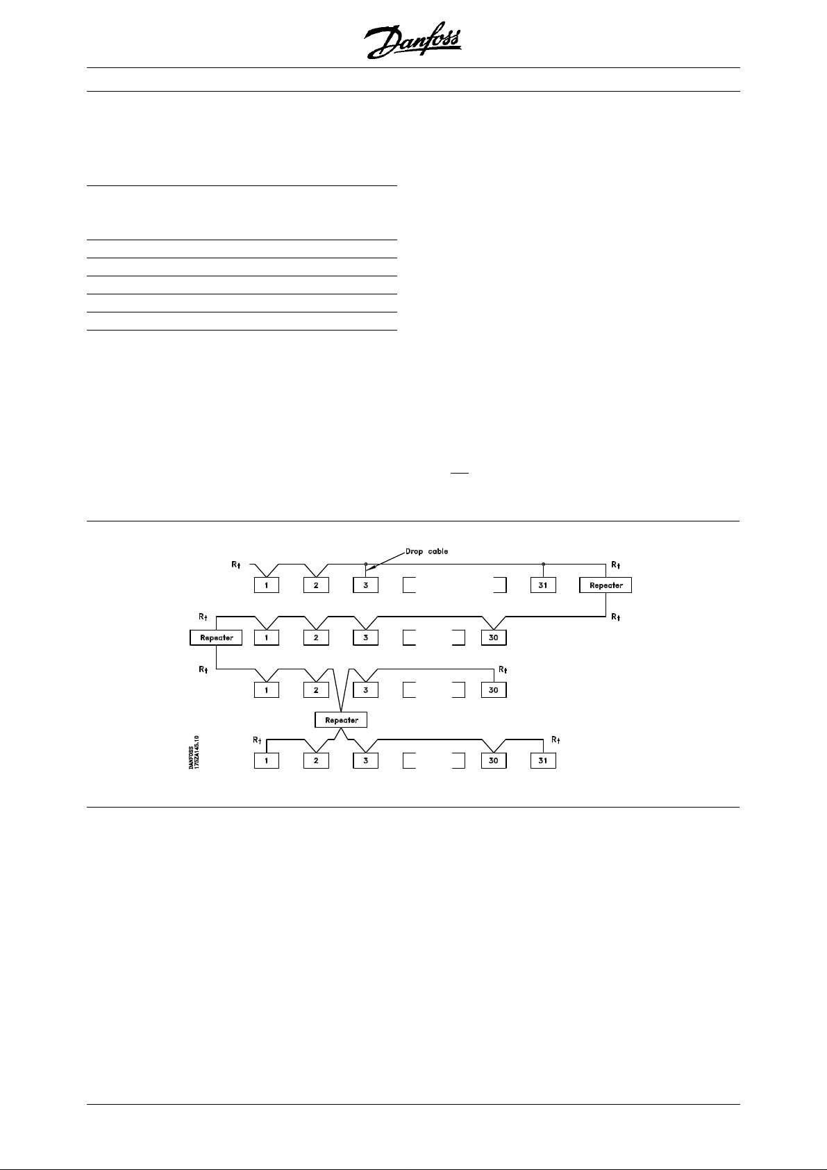
The numbers on the following drawing indicate the
maximum number of stations in each segment. They
are
not the station addresses as each station in the
network must have a unique address.
Segment 1
Segment 2
Segment 3
Segment 4
Rt = termination
resistors
6
MG.90.A2.02 – VL T is a registered Danfoss trademark
Page 7
FCM 300:FCM 300:
FCM 300:
FCM 300:FCM 300:
FCM 300 PROFIBUS / VLT 2800 PROFIBUS
The PROFIBUS Interface
■ Physical connection
The PROFIBUS is connected to the bus line via X100,
terminals 1 and 2.
It is recommended to use a master with a galvanic
isolated bus driver and with over voltage protection
(e.g. zenerdiode).
EMC precautions
The following EMC precautions are recommended to
obtain interference free operation of the PROFIBUS
network. Additional information on EMC can be found
in the design guide on the FC motor (MG.03.Bx.02).
Please also consult the manual of the PROFIBUS
master for further installation guidelines.
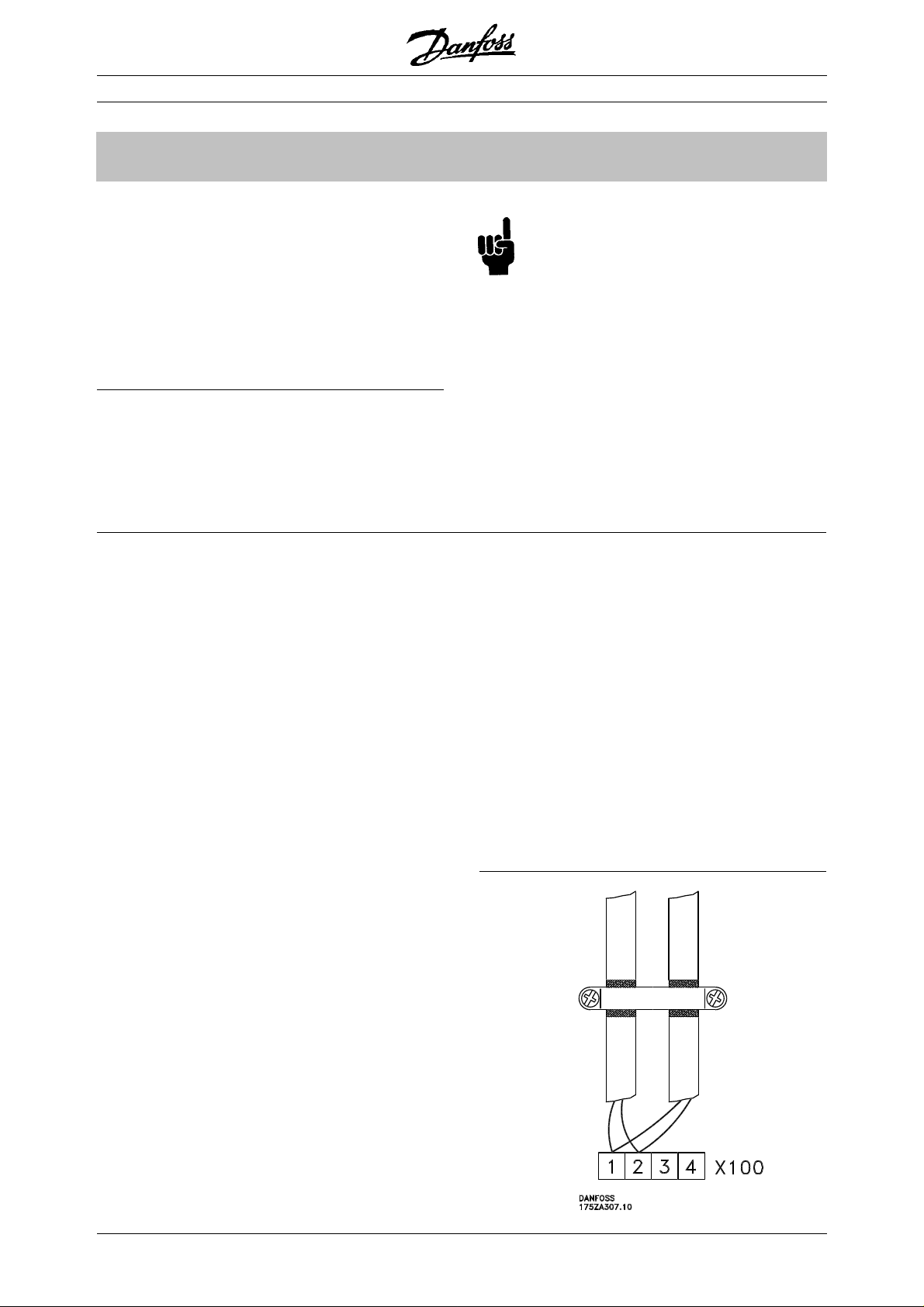
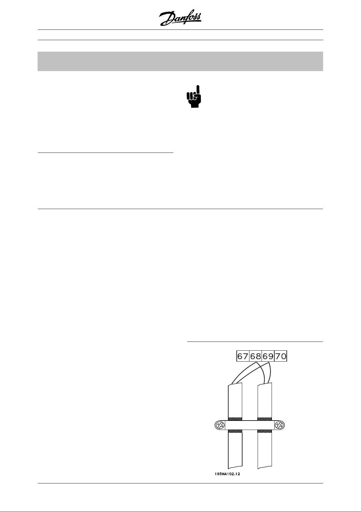
If the PROFIBUS cable has to cross a motor and
brake resistor cable they must cross each other at
an angle of 90°.
- Connection of the cable screen
The screen of the PROFIBUS cable must always
be connected to ground at both ends, that means
the screen must be connected to ground in all
stations connected to the PROFIBUS network. It
is very important to have a low impedance
ground connection of the screen, also at high
frequencies.This can be obtained by connecting
the surface of the screen to ground, for example
by means of a cable clamp or a conductive cable
gland.
The FC motor Series is provided with different
clamps and brackets to enable a proper ground
connection of the PROFIBUS cable screen. The
screen connection is shown in the following
drawing.
Relevant national and local regulations, for
example regarding protective earth
connection, must be observed.
- Cable routing
The PROFIBUS communication cable must be
kept away from motor and brake resistor cables to
avoid coupling of high frequency noise from one
cable to the other. Normally a distance of 200 mm
is sufficient, but it is generally recommended to
keep the greatest possible distance between the
cables, especially where cables are running in
parallel over long distances.
- Earth connection
It is important that all stations connected to the
PROFIBUS network are connected to the same
earth potential. The earth connection must have a
low HF (high frequency) impedance. This can be
achieved by connecting a large surface area of the
cabinet to earth, for example by mounting the FC
motor on a conductive rear plate.
Especially when having long distances between
the stations in a PROFIBUS network it can be
necessary to use additional potential equalizing
cables, connecting the individual stations to the
same earth potential.
Connecting the bus line
MG.90.A2.02 – VL T is a registered Danfoss trademark
7
Page 8
FCM 300:FCM 300:
FCM 300:
FCM 300:FCM 300:
The bus termination
See drawing on page 6
The PROFIBUS Interface
FCM 300 PROFIBUS / VLT 2800 PROFIBUS
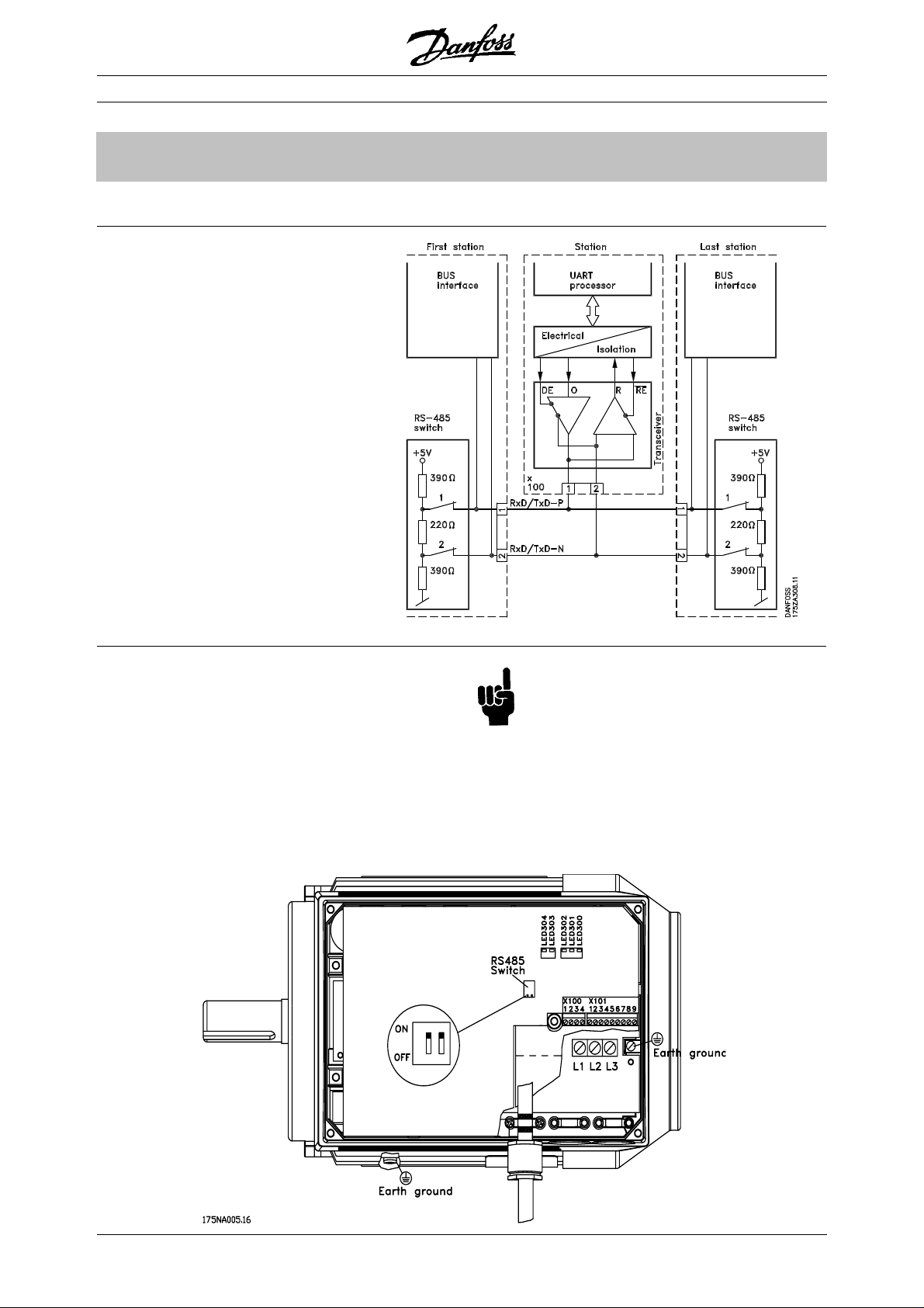
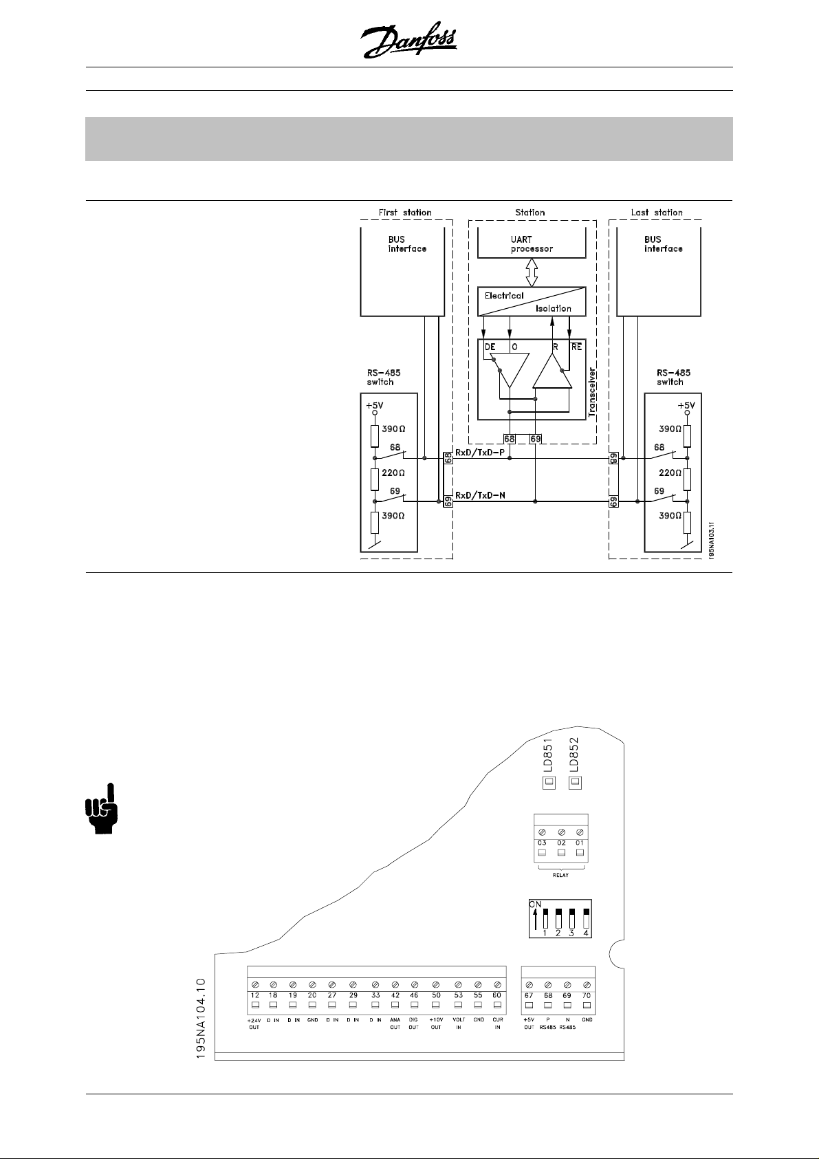
It is essential that the bus line be terminated properly.
A mismatch of impedance may result in reflections
on the line that will corrupt data transmission.
- The PROFIBUS is provided with a suitable
termination which may be activated by the
switches of the RS485 switch block located
just to the left of the terminal block X100 (see
drawing below). The switches should be on to
terminate the bus.
The switches should never be left in opposite
positions. They should either both be ON or
both be OFF!
- Most masters and repeaters are equipped with
their own termination.
- If an external termination circuit consisting of three
resistors is connected to the bus line a 5 V d.c.
power supply must be used, please note that this
must be galvanically isolated from the a.c. line.
8
MG.90.A2.02 – VL T is a registered Danfoss trademark
Page 9

FCM 300:FCM 300:
FCM 300:
FCM 300:FCM 300:
■ LEDs
There are 2 LEDs on the PROFIBUS:
LED303: Lights up when the card is initialized
and ready to communicate. It will
flash while auto baudrate detection is
attempting to detect the actual
baudrate.
LED304: Lights up when the card is
communicating, depending on
baudrate.
A high baudrate results in dim light in LED304.
FCM 300 PROFIBUS / VLT 2800 PROFIBUS
The PROFIBUS Interface
MG.90.A2.02 – VL T is a registered Danfoss trademark
9
Page 10
VLVL
T 2800T 2800
VL
T 2800
VLVL
T 2800T 2800
FCM 300 PROFIBUS / VLT 2800 PROFIBUS
::
:
::
■ Physical connection
The PROFIBUS is connected to the bus line via,
terminals 68 and 69.
It is recommended to use a master with a galvanic
isolated bus driver and with over voltage protection
(e.g. zenerdiode).
The PROFIBUS Interface
EMC precautions
The following EMC precautions are recommended to
obtain interference free operation of the PROFIBUS
network. Additional information on EMC can be found
in the design guide on the VLT 2800 (MG.28.Ex.02).
Please also consult the manual of the PROFIBUS
master for further installation guidelines.
If the PROFIBUS cable has to cross a motor and
brake resistor cable they must cross each other at
an angle of 90°.
- Connection of the cable screen
The screen of the PROFIBUS cable must always
be connected to ground at both ends, that means
the screen must be connected to ground in all
stations connected to the PROFIBUS network. It
is very important to have a low impedance
ground connection of the screen, also at high
frequencies.This can be obtained by connecting
the surface of the screen to ground, for example
by means of a cable clamp or a conductive cable
gland.
The VLT 2800 Series is provided with different
clamps and brackets to enable a proper ground
connection of the PROFIBUS cable screen. The
screen connection is shown in the following
drawing.
Relevant national and local regulations, for
example regarding protective earth
connection, must be observed.
- Cable routing
The PROFIBUS communication cable must be
kept away from motor and brake resistor cables to
avoid coupling of high frequency noise from one
cable to the other. Normally a distance of 200 mm
is sufficient, but it is generally recommended to
keep the greatest possible distance between the
cables, especially where cables are running in
parallel over long distances.
- Earth connection
It is important that all stations connected to the
PROFIBUS network are connected to the same
earth potential. The earth connection must have a
low HF (high frequency) impedance. This can be
achieved by connecting a large surface area of the
cabinet to earth, for example by mounting the VLT
2800 on a conductive rear plate.
Especially when having long distances between
the stations in a PROFIBUS network it can be
necessary to use additional potential equalizing
cables, connecting the individual stations to the
same earth potential.
Connecting the bus line
10
MG.90.A2.02 – VL T is a registered Danfoss trademark
Page 11
VLVL
T 2800T 2800
VL
T 2800
VLVL
T 2800T 2800
The bus termination
See drawing on page 6
FCM 300 PROFIBUS / VLT 2800 PROFIBUS
The PROFIBUS Interface
::
:
::
It is essential that the bus line be terminated properly.
A mismatch of impedance may result in reflections on
the line that will corrupt data transmission.
- The PROFIBUS is provided with a suitable
termination which may be activated by the
switches of the RS485 switch block located
just to the left of the terminal block X100 (see
drawing below). The switches should be on to
terminate the bus.
The switches should never be left in opposite
positions. They should either both be ON or
both be OFF!
- Most masters and repeaters are equipped with
their own termination.
- If an external termination circuit consisting of three
resistors is connected to the bus line a 5 V d.c.
power supply must be used, please note that this
must be galvanically isolated from the a.c. line.
MG.90.A2.02 – VL T is a registered Danfoss trademark
11
Page 12

VLVL
T 2800T 2800
VL
T 2800
VLVL
T 2800T 2800
■ LEDs
There are 2 LEDs on the PROFIBUS:
LD851: Lights up when the card is initialized
and ready to communicate. It will
flash while auto baudrate detection is
attempting to detect the actual
The PROFIBUS Interface
LD852: Lights up when the card is
A high baudrate results in dim light in LD852.
baudrate.
communicating, depending on
baudrate.
::
:
::
FCM 300 PROFIBUS / VLT 2800 PROFIBUS
12
MG.90.A2.02 – VL T is a registered Danfoss trademark
Page 13

FCM 300 PROFIBUS / VLT 2800 PROFIBUS
■ Bus topology
Single master operation with DP
FeaturFeatur
es of DPes of DP
Featur
es of DP (Distributed Periphery)
FeaturFeatur
es of DPes of DP
- Is used by several PLC manufacturers for remote
peripheral I/O communication.
- Supports cyclical communication.
- SRD service gives fast cyclical exchange of
process data between master and slaves.
- Freeze and synchronize function is supported
- Fixed data structure.
- Fixed telegramme size.
- Occupies I/O memory space in PLC proportional
to the number of slaves employed, which may limit
the number of participants. Additional data
require additional I/O memory space.
- Single master
- PLC communicates with telegrams of constant
length
- Fits to time critical requirements
- No need for equidistant transmissions of
set points
Cyclical transmission
1. Set point transmission
2. Actual value feed back
3. New setpoints computed
4. New setpoint transfer
DP should be used when fast cyclical process control
is needed. Such a concept would typically call for
single master operation with a limited number of slave
stations. (A high number of slaves will reduce the
system response).
This could also be the case where control loops are
closed over the bus.
As a very fast alternative it is of course possible to
close the control loop outside the bus.
System layout
Transferring large amount of data where rapid transfer
of process data does not have highest priority
MG.90.A2.02 – VL T is a registered Danfoss trademark
13
Page 14

FCM 300 PROFIBUS / VLT 2800 PROFIBUS
Closing the control loop over the bus
System layout
Closing the control loop outside the fieldbus
for extremely fast feed-back
Rapid Cyclical transmission with PPO using DP
Parameter up-/downloads can be achieved by using
the so-called Parameter / Process Objects - PPOs of 12, 20 or 28 bytes length as specified in the VDI/
VDE 3689 profile, see drawing page 16.
This procedure, however, occupies 8 bytes additional
I/O memory space in the PLC bytes per slave, and
slows down the system (see also “Timing” page 15).
Control of the drives during normal operation is often
very time critical, but it involves very few data, such
as control commands and speed reference. DP is
optimized for fast cyclical communication.
■ Features and services supported by FC motor
and the VLT 2800
Features available as described by the unit
classification
The unit classification as layed out in the PROFIBUS
Profile for VSDs describes the functionality of the unit.
There are 4 classes where class 1 signifies the lowest
performance class, and class 4 the highest.
The FC motor / VLT 2800 is a class 3 unit except for
the following features:
- Fault buffer
- Change access rights for parameter write
- Change access rights for process control
- Time difference
- Hardware configuration ident.
The FC motor / VLT 2800 complies with the following
class 4 features:
- Baudrate > 500 kBaud
- Programmable content of PCD 3 through 6 (10) of
the PPO’s
- PPO type 5
14
MG.90.A2.02 – VL T is a registered Danfoss trademark
Page 15

FCM 300 PROFIBUS / VLT 2800 PROFIBUS
■■
■ FC motor / VLT 2800 response time
■■
The update time via the PROFIBUS connection can
be divided in two parts:
1) The communication time, which is the time it takes
to transmit data from the master to the slave (FC
motor / VLT 2800 with PROFIBUS), and 2) the
internal update time, which is the time it takes to
transmit data between the FC motor / VLT 2800
control card and the PROFIBUS.
Communication time (t
) depends on the actual
com
transmission speed (baudrate) and the type of master
in use. The minimum obtainable communication time
with the FC motor / VLT 2800 with PROFIBUS is
approx. 100 µsec per slave, when using DP
communication with 4 bytes of data (PPO type 3) at 3
Mbaud. More data or lower transmission speed will
increase the communication time.
The internal update time (t
) depends on the type of
int
data in question as there are different channels for the
data transfer where time critical data e.g. control
word has highest priority. The internal update time for
the different types of data are stated below.
Update
Data time, t
Control word/Main reference
(part of PPO) 42 msec
Status word/Actual output frequency
(part of PPO) 40 msec
Parameter read (PCD 1-8) 40 msec
Parameter write (PCD 1-2) 160 msec
Parameter write (PCD 3-4) 320 msec
Parameter write (PCD 5-8) 640 msec
Parameter read (PCV) 41 msec
Parameter write (PCV) 40 msec
Timing
int
■■
■ System update time
■■
The system update time is the time it takes to
update all the slaves in the network when using
cyclical communication. The drawing below shows
the value which is obtainable in theory at 2 input
and 2 output bytes.
MG.90.A2.02 – VL T is a registered Danfoss trademark
15
Page 16

FCM 300 PROFIBUS / VLT 2800 PROFIBUS
■ DP communication relations
DP
Communication according to PROFIBUS DP, i.e. DIN
19245 part 1 & 3, is supported. Consequently a
master that supports PROFIBUS DP must be used.
■ PPO description
A special feature of the PROFIBUS Profile for VSD’s is
the communication object called a PPO, meaning
Parameter-Process Data Object.
The PPO is well suited for fast cyclical data transfer,
and may, as the name implies, carry both process
data and parameters.
The selection of PPO type is made according to the
master request.
A PPO may consist of a parameter part and process
data part. The parameter part can be used for
reading and/or updating the parameters one by one.
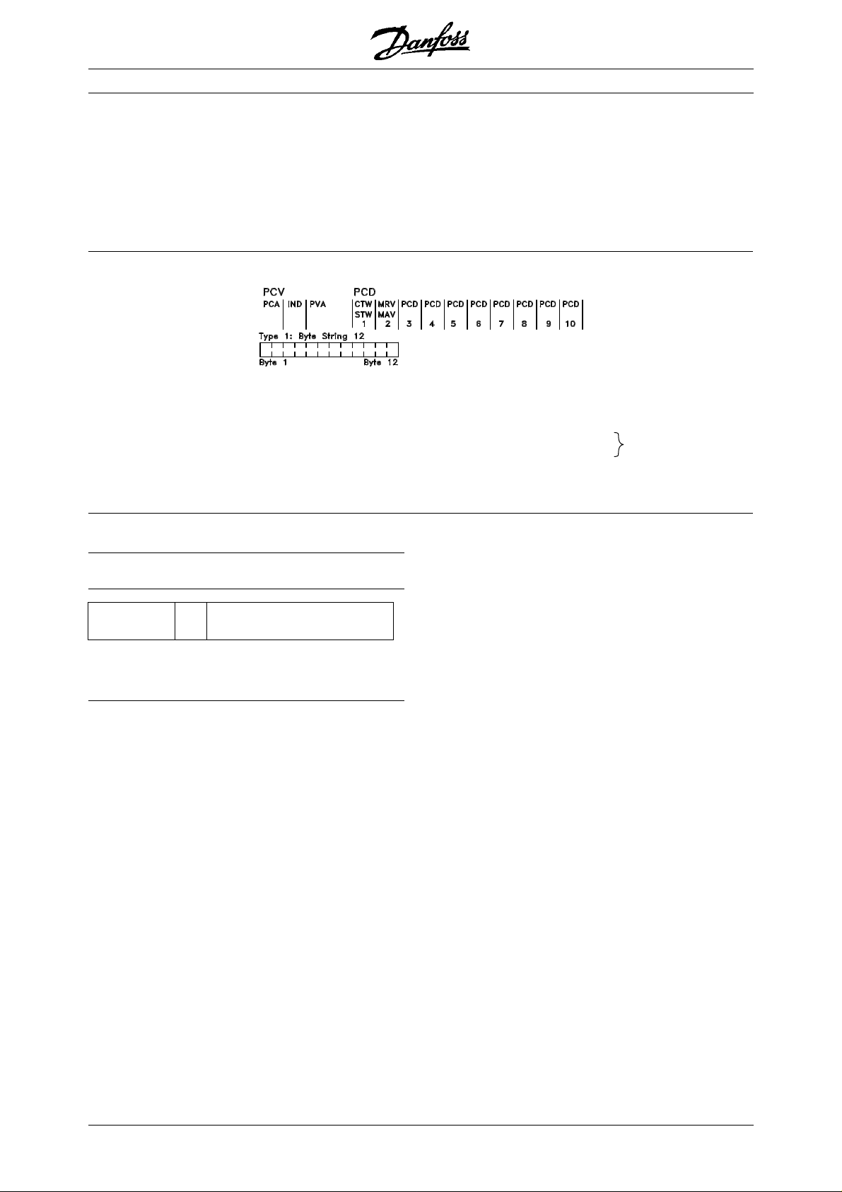
PPO. Parameter-Process Data Object
By DP one of the following shown PPO’s must be used:
By DP communication one of the parameter-process
data objects (PPO’s) described below must be used.
The process data part consists of a fixed part (4
bytes) and a parametrable part (8 or 16 bytes). In the
fixed part control word and speed reference are
transfered to the VLT while status word and actual
output frequency feedback are transfered from the
VLT. In the parametrable part the user chooses which
parameters have to be transfered to (parameter 915)
and which from (parameter 916) the VLT.
Type 1, 2 and 5 consist of the parameter part and 4,
12 and 20 byte process data, respectively.
Type 3 and 4 consist of 4 and 12 byte process data,
respectively.
PCD: Process Data
PCV: Parameter-Characteristics-Value
PCA: Parameter-Characteristics (Bytes 1, 2)
PCA handling below
IND: Subindex (Byte 3), (Byte 4 is not used)
PVA: Parameter value (Bytes 5 to 8)
CTW: Control word
STW: Status word
MRV: Main reference value
MAV: Main actual value (Actual output frequency)
see page 22
16
MG.90.A2.02 – VL T is a registered Danfoss trademark
Page 17

FCM 300 PROFIBUS / VLT 2800 PROFIBUS
■ PCA handling
The PCA portion of the PPO types 1, 2 and 5 will
handle a number of tasks. The master may control
and supervise parameters and request a response
from the slave, while the slave, apart from responding
to a request from the master may transmit a
spontaneous message.
Requests and responses is a handshake procedure
and cannot be batched, meaning that if the master
sends out a Read/write request, it has to wait for the
response, before it sends a new request. The request
or response data value will be limited to max. 4 bytes,
which implies that text strings are not transferable.
PCA - Parameter Characteristics
15141312 11 109876543210
RC SMP PNU
RC: Request/respons Characteristics (Range: 0..15)
SPM: Toggle-Bit for Spontaneous Messages
PNU: Parameter # (Range: 1..1999)
Response Function
0 No response
1 Transfer parameter value (word)
2 Transfer parameter value (long word)
3 Transfer description element
4 Transfer parameter value (array word)
5
Transfer parameter value (array long word)
6 Transfer number of array elements
7 Request rejected (incl. fault #, see below)
8 Not seviceable by PCV interface
9 Spontaneous message (word)
10 Spontaneous message (long word)
11 Spontaneous message (array word)
12 Spontaneous message (array long word)
13-15 Not used
If the slave rejects a request from the master, the RC word in
the PPO-read will indicate this by assuming the value 7.
The fault # will be carried by bytes 7 and 8 in the PVA element.
DP
Request/response handling
The RC portion of the PCA word defines the requests
that may be issued from the master to the slave as
well as what other portions of the PCV (IND and PVA)
are involved.
The PVA portion will transmit word-size parameter
values in bytes 7 and 8, while long word size values
require bytes 5 to 8 (32 bits).
If the Response / Request contains array elements,
the IND will carry the Array Subindex. If parameter
descriptions are involved, the IND will hold the Record
Subindex of the Parameter description.
RC content
Request Function
0 No request
1 Request parameter value
2 Change parameter value (word)
3 Change parameter value (long word)
4 Request description element
5 Change description element
6 Request parameter value (array)
7 Change parameter value (array word)
8
Change parameter value (array long word)
9 Request number of array elements
10-15 Not used
Fault # Interpretation
0 Illegal PNU
1 Parameter value cannot be changed
2 Upper or lower limit exceeded
3 Subindex corrupted
4 No array
5 Data type false
6 Cannot be set by user (reset only)
7 Description element cannot be changed
8 IR required PPO-write not available
9 Description data not available
10 Access group
11 No parameter write access
12 Key word missing
13
14
Text in cyclical transmission not readable
Name in cyclical transmission not readable
15 Text array not available
16 PPO-write missing
17 Request temporarily rejected
18 Other fault
19
Date in cyclical transmission not readable
130 There is no bus access to the parameter
called
131 Data change is not possible because
factory Setup has been selected
MG.90.A2.02 – VL T is a registered Danfoss trademark
17
Page 18

FCM 300 PROFIBUS / VLT 2800 PROFIBUS
■ Parameter and data type structure description
DP
Parameter description:
PNU
Characteristics
Subindex 1
DP has a number of describing attributes (see rigth).
Size of elements
Read/write on parameter description is made by the
PCV part using the RC commands 4/5 and subindex
of the desired description element.
Size attribute
The size index and the conversion index for each
parameter can be taken from the parameter list on
page 36.
Subindex 2
Size attributes
Subindex 4
Lower limit
Subindex 7
Upper limit
Subindex 8
Extended characteristics
Subindex 10
Physical unit Size index Measuring unit Designation Conversion index Conversion factor
0 No dimension 0 1
second s 0 1
-1 0.1
-2 0.01
Time 4 millisecond ms -3 0.001
minute min 70 60
hour h 74 3600
day d 77 86400
watthour Wh 0 1
Energy 8 kilowatthour kWh 3 1000
megawatthour MWh 6 10
milliwatt mW -3 0.001
Power 9
watt W 0 1
kilowatt kW 3 1000
megawatt MW 6 10
Rotation 11 rotation per minute RPM 0 1
Torque 16
newtonmeter Nm 0 1
kilonewtonmeter kNm 3 1000
Temperature 17 degree Celsius °C 0 1
millivolt mV -3 0.001
Voltage 21 volt V 0 1
kilovolt kV 3 1000
milliampere mA -3 0.001
Current 22 ampere A 0 1
kiloampere kA 3 1000
milliohm mOhm -3 0.001
Resistance 23 ohm Ohm 0 1
kiloohm kOhm 3 1000
Ratio 24 per cent % 0 1
Relative change 27 per cent % 0 1
hertz Hz 0 1
Frequency 28
kilohertz kHz 3 1000
megahertz MHz 6 10
gigahertz GHz 9 10
6
6
6
9
18
MG.90.A2.02 – VL T is a registered Danfoss trademark
Page 19

FCM 300 PROFIBUS / VLT 2800 PROFIBUS
■ Object and data types supported by FC motor
and VLT 2800
Data types supported by FC motor and VLT 2800
Data Object Short Description
type Code name
3 5 12 Integer 16
5 5 Unsigned 8
6 5 O2 Unsigned 16
7 5 O4 Unsigned 32
10 5 Byte string
13 5 Time difference
1)
33 5 N2 Standardized value (16 bit)
35 5 V2 Bit sequence
1)
See elaboration below
1)
Time difference
The data type time difference is a time indication in
milliseconds.
Notation: Time difference
Value range: 0 ≤ i ≤ (2
32
-1) milliseconds
Coding: The time is presented as a binary
value of 32 bits (4 bytes). The first
four (MSB) bits are always zero.
Time difference is thus a byte string
of 4 bytes.
Data coding of the data type time difference
Bit Byte 1 Byte 2 Byte 3 Byte 4
80ms223ms 215ms 27ms MSB
70ms222ms 214ms 26ms MSB
60ms221ms 213ms 25ms MSB
50ms220ms 212ms 24ms MSB
4227ms 219ms 211ms 23ms
3226ms 218ms 210ms 22ms
2225ms 217ms 29ms 21ms
1224ms 216ms 28ms 20ms
Standardized value
1)
A liniary value.
14
0% = 0 (0h), 100% is 2
(4000h)
Data type N 2
Range -200% ... 200% – 2
Resolution 2
–14
= 0.0061%
Length 2 bytes
Notation: 2’s complement notation.
MSB is 1st bit after sign bit in 1st byte.
Sign bit = 0 = positive number
Sign bit = 1 = negative number
Bit 8 7 6 5 4 3 2 1
0
Byte 1 SIGN 2
Byte 2 2–72
–12–22–32–42–52–6
2
–82–92–102–112–122–132–14
DP
–14
■ Spontaneous messages
The Spontaneous message is activated by the active
parameters i.e. 538, 540, or 953 and will be carried
with the PCV response, stating PNU and PVA of the
changed active parameter that triggered the
message.
Spontaneous messages are generated when the
value is changed in one of the abovementioned
parameters. It means that a message will be sent
when a warning comes, and when a warning
disappears.
Simultaneously the VLT will toggle the SPM bit (11) of
PCA word (see “PCA handling” page 17).
Bit sequence
16 boolean values for control and presentation of user
functions. Notation is binary.
Bit 87654321
Byte 1 15 14 13 12 11 10 9 8
Byte 2 7 6 5 4 3 2 1 0
The Spontaneous messages will be transmitted until
the master has acknowledged reception of the
message by changing the SPM bit.
Spontaneous messages are only active when
parameter 917 is “ON”!
MG.90.A2.02 – VL T is a registered Danfoss trademark
19
Page 20

Example of SPM execution
DP
In the VLT the SPMs are temporarily stored in a FIFO
buffer. This means that up to 16 consecutive SPMs
can be retained. If only one SPM has entered the
FIFO, the VLT will resume normal communication as
soon as the SPM has been acknowledged by the
master (and the condition causing the SPM been
rectified). If more SPMs are in the FIFO, these will be
transmitted consecutively upon acknowledgement. If
more SPMs are triggered when the FIFO is full, these
will be ignored.
FCM 300 PROFIBUS / VLT 2800 PROFIBUS
PCA
MASTER
REQ 1
REQ 2
SPM 1 ACK.
SPM 2 NOT ACK.
REQ 2
SPM 2 ACK.
SPM BIT
0
0
0
1
1
0
1
0
0
0
SLAVE
RES. 1
SPM 1
SPM 2
SPM 2
RES. 2
■ Synchronize and freeze
The control commands SYNC/UNSYNC and
FREEZE/UNFREEZE are broadcast functions. SYNC/
UNSYNC is used to send syncronized control
commands and/or speed reference to all the
connected slaves (FC motor Series/VLT 2800 Series).
FREEZE/UNFREEZE is used to freeze the status
feedback in the slaves to get syncronized feedback
SYNC/UNSYNC
SYNC/UNSYNC can be used to obtain simultaneous
reactions in several slaves, for example synchronised
start, stop or speed change. A SYNC command will
freeze the actual control word and speed reference,
incoming Process Data will be stored but not used
until a new SYNC command or a UNSYNC command
is received.
from all connected slaves.
See the example below where the left column holds
The synchronize and freeze commands only affect
Process Data (the PCD part of the PPO).
the speed reference send out by the master and the
three right columns hold the actual speed reference
used in each of the three slaves.
Actual slave speed reference
VLT VLT VLT
From DP master to address: Address 3 Address 4 Address 5
1. Speed reference = 50% to address 3 ⇒ 50 % 0 % 0 %
2. Speed reference = 50% to address 4 50% ⇒ 50 % 0 %
3. Speed reference = 50% to address 5 50% 50 % ⇒ 50 %
4. SYNC command to all addresses ⇒ 50 % ⇒ 50 % ⇒ 50 %
5. Speed reference = 75% to address 3 ⇒ 50 % 50 % 50 %
6. Speed reference = 75% to address 4 50% ⇒ 50 % 50 %
7. Speed reference = 75% to address 5 50% 50 % ⇒ 50 %
8. SYNC command to all addresses ⇒ 75 % ⇒ 75 % ⇒ 75 %
9. Speed reference = 100% to address 3 ⇒ 75 % 75 % 75 %
10. Speed reference = 50% to address 4 75 % ⇒ 75 % 75 %
11. Speed reference = 25% to address 5 75 % 75 % ⇒ 75 %
12. UNSYNC command to all addresses ⇒ 100 % ⇒ 50 % ⇒ 25 %
13. Speed reference = 0% to address 3 ⇒ 0% 50% 25%
14. Speed reference = 0% to address 4 0 % ⇒ 0% 25%
15. Speed reference = 0 % to address 5 0 % 0 % ⇒ 0%
20
MG.90.A2.02 – VL T is a registered Danfoss trademark
Page 21

FCM 300 PROFIBUS / VLT 2800 PROFIBUS
FREEZE/UNFREEZE
FREEZE/UNFREEZE can be used to get simultaneous
reading of Process Data for example output current
from several slaves. A FREEZE command will freeze
the current actual values and on request the slave will
send back the value that was present when the
FREEZE command was received. The actual values
will be updated when a new FREEZE or UNFREEZE
command is received.
DP master reads address: Address 3 Address 4 Address 5
1. Address 3 output current = 2A ⇐ 2A 3A 4A
2. Address 4 output current = 5A 2 A ⇐ 5A 2A
3. Address 5 output current = 3A 3 A 2 A ⇐ 3A
4. FREEZE command to all addresses ⇒ 1A ⇒ 3A ⇒ 3A
5. Address 3 output current = 1A ⇐ 4A 2A 5A
6. Address 4 output current = 3A 2 A ⇐ 2A 2A
7. Address 5 output current = 3A 3 A 1 A ⇐ 2A
8. UNFREEZE command to all adresses ⇒ 2A ⇒ 3A ⇒ 4A
Reading as by 1, 2 and 3
See the example below where the left column holds
the current values read by the master and the three
right columns hold the actual output current of the
three slaves.
Actual slave output current
VLT VLT VLT
DP
MG.90.A2.02 – VL T is a registered Danfoss trademark
21
Page 22

FCM 300 PROFIBUS / VLT 2800 PROFIBUS
■ Control word / status word
DP
The bits of the “Control word” tell the VLT how to
react, while the “Status word” bit status will tell the
master the condition of the VLT.
Control word
According to PROFIDRIVE control word (para. 512=0) According to VLT standard (para. 512=1)
Bit Bit = 0 Bit = 1 Bit = 0 Bit = 1
00 (LSB) OFF 1 ON 1 Preset reference
01 OFF 2 ON 2
02 OFF 3 ON 3 DC brake Ramp
03 Motor coasting Enable Coasting Enable
04 Quick-stop Ramp Quick-stop Ramp
05 Freeze output frequency Ramp enable Freeze output Ramp enable
06 Ramp stop Start Ramp stop Start
07 No function Reset No function Reset
08 Jog 1 OFF ON No function Jog
09 Jog 2 OFF ON
10 Data not valid Valid Data not valid Valid
11 No function Slow down No function
12 No function Catch-up No function
13 Setup select Setup select
14
15 (MSB) No function Reversing No function Reversing
Control word
The control words are used to send control
commands to the frequency converter when the
telegram is sent from the master.
The FC motor Series Design Guide (MG.03.BX.02) and the VLT 2800 Series Design Guide (MG.28.EX.02) holds a
detailed description of the control word.
Status word
When the frequency converter returns the frame to
the master, the same two bytes operate as status
from the frequency converter with the following
functions:
Status word
According to PROFIDRIVE control word (para. 512=0) According to VLT standard (para. 512=1)
Bit Bit = 0 Bit = 1 Bit = 0 Bit = 1
00 (LSB) Control not ready Ready
01 VLT not ready Ready VLT not ready Ready
02 Motor coasting Enable Coasting Enable
03 No fault Trip No fault Tri p
04 ON 2 OFF 2 R e s e r v e d
05 ON 3 OFF 3 R e s e r v e d
06 Start enable Start disable R e s e r v e d
07 No warning Warning No warning Warning
08 Speed ≠ ref. Speed = ref. Speed ≠ ref. Speed = ref.
09
10 Out of range Frequency OK Out of range Frequency OK
11 Not running Running Not running Running
12
13 Voltage OK Limit Voltage OK Above limit
14 Torque OK Limit Current OK Above limit
15 (MSB) No thermal warning Thermal warning No thermal warning Thermal warning
The FC motor Series Design Guide (MG.03.BX.02) and the VLT 2800 Series Design Guide (MG.28.EX.02 ) holds a
detailed description of the status word.
22
MG.90.A2.02 – VL T is a registered Danfoss trademark
Page 23
FCM 300 PROFIBUS / VLT 2800 PROFIBUS
■ Example
This example shows how PPO type 1 is used for
changing the ramp-up time (parameter 207) to
10 seconds and for commanding a start and speed
reference of 50%.
PPO. Parameter-Process Data Object
PCD: Process Data
PCV: Parameter-Characteristics-Value
PCA: Parameter-Characteristics (Bytes 1, 2)
PCA handling below
IND: Subindex (Byte 3), (Byte 4 is not used)
PVA: Parameter value (Bytes 5 to 8)
CTW: Control word
STW: Status word
see page 22
MRV: Main reference value
MAV: Main actual value
DP
PCVPCV
PCV
PCVPCV
PCA - Parameter Characteristics
15141312 11 109876543210
RC SMP PNU
RC: Request/respons Characteristics (Range: 0..15)
SPM: Toggle-Bit for Spontaneous Messages
PNU: Parameter # (Range: 1..1999)
PCA part (byte 1-2)
The R
C part tells what the PCV part must be used for.
The functions available appear from the table, page
17.
When a parameter is to be changed, choose value 2
or 3, in this example 3 is chosen, because parameter
207 covers a long word (32 bits).
SPM bit:
The function is explained on page 19, in the example
the function Spontaneous Messages is not applied
(parameter 917 = OFF), therefore SPM is set for 0.
PNU = Parameter number:
Parameter number is set for: 207 = CF Hex.
This means that the value of the PCA part is 30CF
Hex.
IND (bytes 3-4):
Used when reading/changing parameters with
subindex, for example parameter 915. In the example
bytes 3 and 4 are set for 00 Hex.
PVA (bytes 5-8):
The data value of parameter 207 must be changed to
10.00 seconds. The value transmitted must be 1000,
because the conversion index for parameter 207 is
-2, this means that the value received by VLT is
divided by 100, making VLT perceive 1000 as 10.00.
Bytes 5-8 = 1000 = 03E8 Hex.
MG.90.A2.02 – VL T is a registered Danfoss trademark
23
Page 24

PCDPCD
PCD
PCDPCD
DP
CTW according to Profidrive profile:
Control words consisting of 16 bits, the meaning of
the various bits appears from the table, page 22.
The following bit pattern sets all necessary start
commands: 0000 0100 0111 1111 = 047F Hex.*
0000 0100 0111 1110 = 047E Hex.*
0000 0100 0111 1111 = 047F Hex.
Quickstop: 0000 0100 0110 1111 = 046F Hex.
Stop: 0000 0100 0011 1111 = 043F Hex.
* Only necessary at power up.
MRV:
Speed reference, the data format is "Standardized
value", see page 19. 0 Hex = 0% and 4000 Hex =
100%.
FCM 300 PROFIBUS / VLT 2800 PROFIBUS
- A positive response of the above example may
look like this:
Byte Value
PCA 1 20
PCA 2 CF
IND 3 00
PCV
PCD
IND 4 00
PVA 5 00
PVA 6 00
PVA 7 03
PVA 8 E8
STW 9 0F
STW 10 07
MAV 11 20
MAV 12 00
In the example 2000 Hex is used corresponding to
50% of maximum frequency (parameter 202).
The whole PPO therefore gets the following value in
Hex:
Byte Value
PCA 1 30
PCA 2 CF
IND 3 00
PCV
PCD
The Process data within the PCD part is acting on the
VLT immediately, and can be updated from the
master as quickly as possible.
IND 4 00
PVA 5 00
PVA 6 00
PVA 7 03
PVA 8 E8
CTW 9 04
CTW 10 7F
MRV 11 20
MRV 12 00
The PCD part responds according to the state and
parametration of the VLT.
The PCV part responds as:
PCA: As the request telegram, but here the RC part is
taken from the response table on page 16. In this
example RC is 2Hex, which is a confirmation that a
parameter value of the type long word (32 bit) has
been transferred.
IND is not used in this example.
PVA: 03E8Hex in the PVA part tells that the value of
the parameter in question (207) is 1000 which
corresponds to 10.00.
STW: 0F07 Hex means that the motor is running and
there are no warnings or faults (for details see Status
word table on page 22).
MAV: 2000 Hex tells that the output frequency is 50%
of max. frequency.
The PCV part is a “hand shake” procedure which
means that the VLT has to acknowledge the
command, before a new one can be written.
24
MG.90.A2.02 – VL T is a registered Danfoss trademark
Page 25

FCM 300 PROFIBUS / VLT 2800 PROFIBUS
- A negative response may look like this:
Byte Value
PCA 1 70
PCA 2 00
IND 3 00
PCV
PCD
RC is 7 Hex which means that the request has been
rejected, and the fault number can be found in the
PVA part. In this case the fault number is 2 which
means that the upper or lower limit of the parameter
is exceeded. See fault number table on page 17.
IND 4 00
PVA 5 00
PVA 6 00
PVA 7 00
PVA 8 02
STW 9 0F
STW 10 07
MAV 11 20
MAV 12 00
DP
MG.90.A2.02 – VL T is a registered Danfoss trademark
25
Page 26

DP
FCM 300:FCM 300:
FCM 300:
FCM 300:FCM 300:
■■
■ GSD-file
■■
The GSD-file is a DP “standard” text file containing
the necessary data for configuring DP slaves within a
standard DP master.
FCM 300 PROFIBUS / VLT 2800 PROFIBUS
GSD-file: DA010403.GSD
GSD-file for Danfoss FCM 300 Series with
PROFIBUS
#Profibus_DP
Vendor_Name = "DANFOSS DRIVES A/S";
Model_name = "VLT SERIES FCM 300 PROFIBUS“;
Revision = "00";
Ident_Number = 0x0403;
Protocol_Ident = 0;
Station_type = 0;
FMS_supp = 0;
Hardware_Release = "2.0";
Software_Release = "1.10";
9.6_supp = 1;
19.2_supp = 1;
93.75_supp = 1;
187.5_supp = 1;
500_supp = 1;
1.5M_supp = 1;
3M_supp = 1;
6M_supp = 0;
12M_supp = 0;
MaxTsdr_9.6 = 60;
MaxTsdr_19.2 = 60;
MaxTsdr_93.75 = 60;
MaxTsdr_187.5 = 60;
MaxTsdr_500 = 100;
MaxTsdr_1.5M = 150;
MaxTsdr_3M = 250;
Redundancy = 0;
Repeater_Ctr_Sig = 0;
24V_Pins = 0;
Freeze_Mode_supp = 1;
Sync_Mode_supp = 1;
Auto_Baud_supp = 1;
Set_Slave_add_supp = 1;
Usr_Prm_Data_Len = 0;
Min_Slave_intervall = 40;
Modular_Station = 1;
Max_Module = 2;
Max_Input_Len = 28;
Max_Output_Len = 28;
Max_Data_Len = 56;
Module = "PPO Typ 1 Module consistent PCD" 0xF3,
0xF1; EndModule;
Module = "PPO Typ 1 Word consistent PCD" 0xF3,
0x71; EndModule;
Module = "PPO Typ 2 Module consistent PCD" 0xF3,
0xF5; EndModule;
Module = "PPO Typ 2 Word consistent PCD" 0xF3,
0x75; EndModule;
Module = "PPO Typ 3 Module consistent PCD" 0xF1;
EndModule;
Module = "PPO Typ 3 Word consistent PCD" 0x71;
EndModule;
Module = "PPO Typ 4 Module consistent PCD" 0xF5;
EndModule;
Module = "PPO Typ 4 Word consistent PCD" 0x75;
EndModule;
Module = "PPO Typ 5 Module consistent PCD" 0xF3,
0xF9; EndModule;
Module = "PPO Typ 5 Word consistent PCD" 0xF3,
0x79; EndModule;
The VLT can also accept word concistency in
the PCD modules, whereas the PCV portion
must be module consistent.
26
MG.90.A2.02 – VL T is a registered Danfoss trademark
Page 27

VLVL
T 2800T 2800
VL
T 2800
VLVL
T 2800T 2800
■■
■ GSD-file
■■
The GSD-file is a DP “standard” text file containing
the necessary data for configuring DP slaves within a
standard DP master.
::
3 MBaud 3 MBaud
:
3 MBaud
::
3 MBaud 3 MBaud
FCM 300 PROFIBUS / VLT 2800 PROFIBUS
DP
GSD-file: DA010404.GSD
GSD-file for Danfoss VLT® 2800 Series
with PROFIBUS
#Profibus_DP
Vendor_Name = „DANFOSS DRIVES A/S“;
Model_name = „VLT® SERIES 2800“;
Revision = „00“;
Ident_Number = 0x0404;
Protocol_Ident = 0;
Station_type = 0;
FMS_supp = 0;
Hardware_Release = „2.0“;
Software_Release = „1.00“;
9.6_supp = 1;
19.2_supp = 1;
93.75_supp = 1;
187.5_supp = 1;
500_supp = 1;
1.5M_supp = 1;
3M_supp = 1;
6M_supp = 0;
12M_supp = 0;
MaxTsdr_9.6 = 60;
MaxTsdr_19.2 = 60;
MaxTsdr_93.75 = 60;
MaxTsdr_187.5 = 60;
MaxTsdr_500 = 100;
MaxTsdr_1.5M = 150;
MaxTsdr_3M = 250;
Redundancy = 0;
Repeater_Ctr_Sig =0;
24V_Pins = 0;
Freeze_Mode_supp = 1;
Sync_Mode_supp = 1;
Auto_Baud_supp = 1;
Set_Slave_add_supp = 1;
Usr_Prm_Data_Len = 0;
Min_Slave_Intervall = 10;
Modular_Station = 1;
Max_Module = 2;
Max_Input_Len = 28;
Max_Output_Len = 28;
Max_Data_Len = 56;
Max_Diag_Data_Len = 6;
Module = „PPO Typ 1 Module consistent PCD“ 0xF3,
0xF1;
EndModule;
Module = „PPO Typ 1 Word consistent PCD „ 0xF3,
0x71;
EndModule;
Module = „PPO Typ 2 Module consistent PCD“ 0xF3,
0xF5;
EndModule;
Module = „PPO Typ 2 Word consistent PCD „ 0xF3,
0x75;
EndModule;
Module = „PPO Typ 3 Module consistent PCD“ 0xF1;
EndModule;
Module = „PPO Typ 3 Word consistent PCD „ 0x71;
EndModule;
Module = „PPO Typ 4 Module consistent PCD“ 0xF5;
EndModule;
Module = „PPO Typ 4 Word consistent PCD „ 0x75;
EndModule;
Module = „PPO Typ 5 Module consistent PCD“ 0xF3,
0xF9;
EndModule;
Module = „PPO Typ 5 Word consistent PCD „ 0xF3,
0x79;
EndModule;
The VLT can also accept word concistency in
the PCD modules, whereas the PCV portion
must be module consistent.
MG.90.A2.02 – VL T is a registered Danfoss trademark
27
Page 28

VLVL
T 2800: 12 MBaudT 2800: 12 MBaud
VL
T 2800: 12 MBaud
VLVL
DP
■■
■ GSD-file
■■
T 2800: 12 MBaudT 2800: 12 MBaud
The GSD-file is a DP “standard” text file containing
the necessary data for configuring DP slaves within a
standard DP master.
FCM 300 PROFIBUS / VLT 2800 PROFIBUS
GSD-file: DA010405.GSD
GSD-file for Danfoss VLT® 2800 Series
with PROFIBUS
#Profibus_DP
Vendor_Name = "DANFOSS DRIVES A/S";
Model_name = "VLT® 2800 12MB";
Revision = "00";
Ident_Number = 0x0405;
Protocol_Ident = 0;
Station_type = 0;
FMS_supp = 0;
Hardware_Release = "5.0";
Software_Release = "2.20";
9.6_supp = 1;
19.2_supp = 1;
93.75_supp = 1;
187.5_supp = 1;
500_supp = 1;
1.5M_supp = 1;
3M_supp = 1;
6M_supp = 1;
12M_supp = 1;
MaxTsdr_9.6 = 60;
MaxTsdr_19.2 = 60;
MaxTsdr_93.75 = 60;
MaxTsdr_187.5 = 60;
MaxTsdr_500 = 100;
MaxTsdr_1.5M = 150;
MaxTsdr_3M = 250;
MaxTsdr_6M = 450;
MaxTsdr_12M = 800;
Redundancy = 0;
Repeater_Ctr_Sig =0;
24V_Pins = 0;
Freeze_Mode_supp = 1;
Sync_Mode_supp = 1;
Auto_Baud_supp = 1;
Set_Slave_add_supp = 1;
Usr_Prm_Data_Len = 0;
Min_Slave_Intervall = 06;
Modular_Station = 1;
Max_Module = 2;
Max_Input_Len = 28;
Max_Output_Len = 28;
Max_Data_Len = 56;
Max_Diag_Data_Len = 6;
Module = "PPO Typ 1 Module consistent PCD" 0xF3,
0xF1;
EndModule;
Module = "PPO Typ 1 Word consistent PCD " 0xF3,
0x71;
EndModule;
Module = "PPO Typ 2 Module consistent PCD" 0xF3,
0xF5;
EndModule;
Module = "PPO Typ 2 Word consistent PCD " 0xF3,
0x75;
EndModule;
Module = "PPO Typ 3 Module consistent PCD" 0xF1;
EndModule;
Module = "PPO Typ 3 Word consistent PCD " 0x71;
EndModule;
Module = "PPO Typ 4 Module consistent PCD" 0xF5;
EndModule;
Module = "PPO Typ 4 Word consistent PCD " 0x75;
EndModule;
Module = "PPO Typ 5 Module consistent PCD" 0xF3,
0xF9;
EndModule;
Module = "PPO Typ 5 Word consistent PCD " 0xF3,
0x79;
EndModule;
The VLT can also accept word concistency in
the PCD modules, whereas the PCV portion
must be module consistent.
28
MG.90.A2.02 – VL T is a registered Danfoss trademark
Page 29

FCM 300 PROFIBUS / VLT 2800 PROFIBUS
MG.90.A2.02 – VL T is a registered Danfoss trademark
29
Page 30

FCM 300 PROFIBUS / VLT 2800 PROFIBUS
■ FC motor and VLT 2800 parameters
Only the PROFIBUS specific parameters (800 - 805
and 904 . . ) are described in this manual. All other
parameters and their functions are unaffected by the
PROFIBUS option. We refer to the parameter
Parameters
description in the design guide on the FC motor
Series (MG.03.Bx.02) and the design guide on the
VLT 2800 Series (MG.28.Ex.02).
Special attention must be given to the following
parameters that are not described in this manual:
- 502 - 508: Selection of how to gate PROFIBUS
control commands with control
commands on the digital inputs of the
FC motor / VLT2800.
- 512: Control word profile, selects a control
word according to PROFIDRIVE or a
Danfoss specified control word.
- 515 - 543:Data readout parameters that can be
used to read various actual data from
the VLT, as for example actual status
on the analog and digital inputs of the
FC motor / VLT 2800 thus using these
as inputs to the master.
■ PROFIBUS specific parameters
800 Protocol select (PROTOCOL SELECT)
✭ DP [1]
804 Bus time out function (TIME OUT FUNCT.)
Selection:
✭ Off (OFF) [0]
Freeze output frequency (FREEZE OUTPUT) [1]
Stop with auto restart (STOP) [2]
Output frequency = JOG freq. (JOGGING) [3]
Output freq. = Max. freq. (MAX SPEED) [4]
Stop with trip (STOP AND TRIP) [5]
Select Setup 2 [8]
Function:
The time out counter is triggered at the first reception
of a valid control word i.e. bit 10 = ok, when DP is
used.
The time out function can be activated in two different
ways:
1. CTW is not updated within the time specified in
parameter 803.
2. Time out is triggered if the CTW is not valid, see
parameter 805.
The FC motor / VLT 2800 remains in time out state
until one of the following conditions is true:
1. Valid control word (Bit 10 = ok) is received. If Stop
with trip is selected, reset must also be activated.
If Select setup 2 is selected, the FC motor / VLT
2800 will remain in Setup 2 until parameter 4 is
changed.
2. Parameter 804 = Off ⇒ control via PROFIBUS is
resumed and the most recent control word is
used.
Function:
Selection of the PROFIBUS protocol supported by the
master.
Description of selections:
-DP: Communication according to DIN 19245 part
3.
Updating parameter 800, even with an
unchanged data value, will initialise the
PROFIBUS option, meaning that all
communication parameters such as slave addresses,
PPO type etc. will be updated.
803 Bus time out (BUS TIME OUT)
Selection:
✭ 1 - 99sec 1 sec
✭ Factory setting
Description of selections:
- Freeze output frequency: Freeze output frequency
until communication is resumed.
- Stop with auto restart: Stop with auto restart
when communication is resumed.
- Output frequency = JOG freq.: Motor will run at
JOG frequency until communication is
resumed.
- Output frequency = Max. freq.: Motor will run at
max. frequency until communication is resumed.
- Stop with trip: Motor is stopped, reset needed for
restart, see explanation above.
- Select setup 2.
30
MG.90.A2.02 – VL T is a registered Danfoss trademark
Page 31

FCM 300 PROFIBUS / VLT 2800 PROFIBUS
805 Function of control word bit 10
(Bit 10 function)
Selection:
No function (NO FUNCTION) [0]
✭ Bit 10 = 1 ⇒ CTW active
(BIT 10 = 1 ⇒ CTW ACTIVE) [1]
Bit 10 = 0 ⇒ CTW active
(BIT 10 = 0 ⇒ CTW ACTIVE) [2]
Bit 10 = 0 ⇒ time out
(BIT 10 = 0 ⇒ TIME OUT) [3]
Function:
According to the PROFIDRIVE profile, control word
and speed reference will be ignored if bit 10 of the
control word is 0, but parameter 805 lets the user
change the function of bit 10. This is some times
necessary as some masters are setting all bits to 0 in
various fault situations. In these cases it makes sense
to change the function of bit 10 so that the FC motor/
VLT 2800 is commanded to stop (coast) when all bits
are 0.
Description of selections:
- Bit 10 = 1 ⇒ CTW active: Control word and speed
reference is ignored if bit 10 = 0.
- Bit 10 = 0
reference is ignored if bit 10 = 1. If all bits of the
control word are 0 the FC motor / VLT 2800
reaction will be coasting.
- Bit 10 = 0
selected in parameter 804 is activated when bit 10
is 0.
- No function: Bit 10 is ignored, i.e. control word
and speed reference is always valid.
⇒
CTW active: Control word and speed
⇒
time out: The time out function
904 PPO type select for DP (PPO TYPE SELECT)
Parameters
Selections:
✭ PPO type 1 (PPO TYPE 1) [900]
PPO type 2 (PPO TYPE 2) [901]
PPO type 3 (PPO TYPE 3) [902]
PPO type 4 (PPO TYPE 4) [903]
PPO type 5 (PPO TYPE 5) [905]
Function:
The selection is valid for read and write, i.e. the same
PPO type must be used for read and write.
Description of selections:
- PPO type 1: 12 byte PPO with parameter channel
for read and write of parameters and 4 bytes of
process data (control/status word and reference/
actual output frequency).
- PPO type 2: 20 byte PPO as PPO type 1 with 8
additional bytes of selectable process data.
- PPO type 3: 4 byte process data (control/status
word and reference/actual output frequency).
- PPO type 4: 12 byte process data, as process
data part of PPO type 2.
- PPO type 5: 28 byte as PPO type 2 with 8
additional bytes of selectable process data.
A detailed description of the PPO types can be found
on page 23.
Change of parameter 904 is executed when
parameter 800 is updated or at next power up.
✭ Factory setting
MG.90.A2.02 – VL T is a registered Danfoss trademark
31
Page 32

FCM 300 PROFIBUS / VLT 2800 PROFIBUS
915 PCD config. write (PCD IN WR-)
Selections:
Sub index 1 (PCD1) Parameter #
Sub index 2 Parameter #
Parameters
Sub index 3 Parameter #
Sub index 4 Parameter #
Sub index 5 Parameter #
Sub index 6 Parameter #
Sub index 7 Parameter #
Sub index 8 Parameter #
Function:
Different parameters can be assigned to PCD 1-8 of
the PPO’s (the number of PCD’s depends on the PPO
type). The values in PCD 1-8 will be written to the
selected parameters as data values.
Write access via PROFIBUS or standard RS 485.
Description of selections:
The order of the subindexes corresponds to the order
of the PCD’s in the PPO, i.e. subindex 1 ≈ PCD 1,
subindex 2 ≈ PCD 2 and so on. Each subindex can
hold the number of the FC motor / VLT 2800
parameters with write access, but it is only possible
to write 2 byte values (least significant bytes) to
parameters with 4 byte data values because 1 PCD
consists of only 2 bytes.
916 PCD config. read (PCD IN RD-)
Selections:
Sub index 1 (PCD 1) Parameter #
Sub index 2 Parameter #
Sub index 3 Parameter #
Sub index 4 Parameter #
Sub index 5 Parameter #
Sub index 6 Parameter #
Sub index 7 Parameter #
Sub index 8 Parameter #
Function:
Different parameters can be assigned to PCD 1-8 of
the PPO’s (the number of PCD’s depends on the PPO
type). PCD 1-8 will hold the actual data value of the
selected parameters.
Description of selections:
The order of the subindexes corresponds to the order
of the PCD’s in the PPO, i.e. subindex 1 ≈ PCD 1,
subindex 2 ≈ PCD 2 and so on. Each subindex can
hold the number of any of the FC motor / VLT 2800
parameters, but it is only possible to read 2 byte
values (least significant bytes) from parameters with 4
byte data values as 1 PCD consists of only 2 bytes.
917 Activate spontaneous messages
(SPONT. MES)
Selections:
✭ Off (OFF) [0]
On (ON) [1]
Function:
The spontaneous messages function can be switched
on if it is desired to make the FC motor / VLT 2800 issue
a message when a warning or an alarm comes up.
Unread spontaneous messages will be stored
in a 16 elements FIFO buffer.
Description of selections:
- OFF: The FC motor / VLT 2800 will not issue
spontaneous messages or event notification in
case of a warning or an alarm.
- ON: The FC motor / VLT 2800 will issue a
spontaneous message when warnings or alarms
are coming up.
918 Station address (STATION ADDR)
Selections:
1-126
✭ 0
Function:
All stations connected to the same bus must have a
unique address. The station address can be set in
parameter 918.
Change parameter 918 is executed at next
power up and if parameter 800 is updated.
Write access via Profibus or standard RS 485.
✭ Factory setting
32
MG.90.A2.02 – VL T is a registered Danfoss trademark
Page 33

FCM 300 PROFIBUS / VLT 2800 PROFIBUS
953 Warning parameter 1 (WARN. PARA)
Selections:
Read only
Function:
A 16 bit bitstring where each bit is associated with a
specific warning according to the list below.
Bit Bit = “1” when:
0 LSB Connection with DP-master is not ok
1 Not used
2 FDL (Field-bus Data link Layer) is not ok
3 Clear data command received
4 Actual value is not updated
5 Spontaneous message FIFO overflow
6 PROFIBUS ASIC is not transmitting
7 Initialising of PROFIBUS option is not ok
8 Not used
9 Not used
10 Not used
11 Not used
12 Fatal DPR-handling error/Error code
during init.: Bit 0
13 Fatal DPR-handling error/Error code
during init.: Bit 1
14 Fatal DPR-handling error/Error code
during init.: Bit 2
15 MSB Fatal DPR-handling error/Error code
during init.: Bit 3
If errors occur during DPR-handling (bit 7 not
asserted)
Code
0OK
1 Fatal error in warning channel
2 Fatal error in spontaneous channel
3 Fatal error in channel for input of process data
4 Fatal error in channel for output of process data
5 Fatal error in parameter channel 1
6 Fatal error in parameter channel 2
7 Fatal error in parameter channel 3
15 Fatal error in DPR form SPC3
967 Control word
Selections:
16 bits binary code
See page 22.
968 Status word
Selections:
Read only
See page 22.
Parameters
Explanation of errExplanation of err
Explanation of err
Explanation of errExplanation of err
If init. went wrong (bit 7 asserted) following codes are
defined:
Code
0OK
1 Init. channel not empty
2 No resp. on command „Init SPC3 controller“
3 No resp. on command „No action“
4 No resp. on writing init.-data
5 No valid resp. on writing init.-data
6 No positive resp. on writing init.-data
MG.90.A2.02 – VL T is a registered Danfoss trademark
or codes:or codes:
or codes:
or codes:or codes:
33
Page 34

FCM 300 PROFIBUS / VLT 2800 PROFIBUS
970 Edit set up selection (EDIT SETUP SELECT)
Selections:
Factory setup (FACTORY SETUP) [0]
Setup 1 (SETUP 1) [1]
Parameters
Setup 2 (SETUP 2) [2]
✭ Active setup (ACTIVE SETUP) [5]
Function:
As parameter 005, described in the FCM 300 design
guide (MG.03.Bx.02) and the VLT 2800 design guide
(MG.28.Ex.02).
971 Store data values (STORE DATA VALUE)
Selections:
✭ No action (NO ACTION) [0]
Store active setup (STORE ACTIVE SETUP) [1]
Store edit setup (STORE EDIT SETUP) [2]
Store all setups (STORE ALL SETUPS) [3]
Function:
Parameter values changed via PROFIBUS is only
stored in RAM meaning that the changes are lost at
power down. This parameter is used to activate a
function that stores all parameter values in the
EEPROM thus retaining changed parameter values at
power down.
Description of selections:
No action: The store function is inactive.
Store active setup: All parameter values in the active
setup will be stored in the EEPROM. The value
returns to No action when all parameter values have
been stored.
Store edit setup: All parameter values in the setup
you are editing will be stored in the EEPROM. The
value returns to No action when all parameter values
have been stored.
Store all setups: All parameter values in both setups
will be stored in the EEPROM. The value returns to
No action when all parameter values have been
stored.
980-982 Defined parameters (DEFINED PNU'S)
Selections:
Read only
Function:
The three parameters hold a list of all the parameters
that are defined in the FC motor / VLT 2800. It is
possible to read single elements of the list by DP by
using the corresponding subindex. The subindexes
start at 1 and follow the order of the parameter
numbers.
Each parameter holds up to 116 elements (parameter
numbers).
When a 0 is returned as parameter number the list
ends.
990-992 Modified parameters
(MODIFIED PNU'S)
Selections:
Read only
Function:
The three parameters hold a list of all the FC motor /
VLT 2800 parameters that have been changed from
factory setting. It is possible to read single elements
of the list by DP by using the corresponding subindex.
The subindexes start at 1 and follow the order of the
parameter numbers. Each parameter holds up to 116
elements (parameter numbers). The number of
parameters (990, 991 and 992) in use depends on
how many parameters have been changed from
factory setting.
Read only parameters, as for example data read out
parameters, will not be registered as modified
eventhough they are changing.
When a 0 is returned as parameter number the list
ends.
✭ Factory setting
34
MG.90.A2.02 – VL T is a registered Danfoss trademark
Page 35

FCM 300 PROFIBUS / VLT 2800 PROFIBUS
■ Warning and alarm messages
There is a clear distinction between alarms and
warnings. In the case of an alarm, the FC motor / VLT
2800 will enter a fault condition. After the cause for
the alarm has been cleared, the master will have to
acknowledge the alarm message for the FC motor /
VLT 2800 to start operating again. A warning, on the
other hand may come when a warning condition
appears, and disappear when conditions return to
normal without interfering with the process.
Warnings
Any warning within the FC motor / VLT 2800 is
represented by a single bit within a warning word. A
warning word is always an active parameter. Bit
status FALSE [0] means no warning, while bit status
TRUE [1] means warning.
Any bit change in the warning word will result in a
Spontaneous message being issued.
In addition to the warning word message the master
will also be notified through a change of bit 7 in the
Status Word.
■ Spontaneous messages
If a fault or warning condition should occur, the FC
motor / VLT 2800 will, if the proper communicative
relationship has been established, issue a
Spontaneous message to communication partners.
Instead of responding to the master’s request, the FC
motor / VLT 2800 will exchange the requested
response with the alarm or the warning message.
Warnings and alarms will trigger a Spontaneous
message. The same is true with any change to an
active parameter.
Warning and alarm messages
Alarms
Following an Alarm message the FC motor / VLT
2800 will enter Fault condition. Only after the fault has
been alleviated and the master has acknowledged the
alarm message by setting bit 7 in the Control word,
can the FC motor /VLT 2800 resume operation.
Any alarm within the FC motor / VLT 2800 is
represented by a single bit within an alarm word. An
alarm word is always an action parameter. Bit status
FALSE [0] means no fault, while bit status TRUE [1]
means fault.
Any bit change in the alarm word will result in a
Spontaneous message being issued.
MG.90.A2.02 – VL T is a registered Danfoss trademark
35
Page 36

■ Abbreviations
English German Elaboration
Glossary
ACI - Acyclical Control Interval
ALI - Aplication Layer Interface
ATTR - Attribute
BRCT - Broadcast
CCI - Cyclical Control Interval
CR KR Communication Reference
CRL KBL Communication Reference List
CSRD - Cyclical Send and Request Data
CT Typ Connection Type
CTW STW Control Word
DA - Destination Address
DP - Distributed Periphery
EIA - Electronic Industries Association: Specifiers of the EIA Standard RS 485-A
EMC EMV Electromagnetic Compatibility
EN - Event Notification
FIFO - First In First Out
HSA - Highest Station Address
Hd - Hamming distance
HPFB - High Performance Field Bus
IND - Subindex
I/O E/A Input/Output
ISO - International Standards Organization
IR - Information Report
LSAP - Local Service Access Point
LSB - Least Significant Bit
MSB - Most Significant Bit
MAP - Manufacturing Automation Protocol
MAV HIW Main Actual Value
MMS - Manufacturing Message Specification
MRV HSW Main Reference Value
MSAC MZAC Master-Slave connection for acyclical transmission
MSAC_SI MZAC_SI Master-Slave connection for acyclical transmission with slave initiative
MSCY MSZY Master-Slave connection for cyclical transmission
MSCY_SI MSZY_SI Master-Slave connection for cyclical transmission with slave initiative
MULT - Multicast
OD OV Object Directory
PC - Personal Computer
PCA PKE Parameter Characteristics
PCD PZD Process Data
PCV PKW Parameter-Characteristics-Value
PDU - Protocol Data Unit
PLC SPS Programmable Logic Control
PNU - Parameter Number
PPO - Parameter-Process Data Object
PVA PWE Parameter Value
RAC - Receive Acknowledged request Counter
RADR - Remote Address
RC AK Request/Response Characteristics
RCC - Receive Confirmed request Counter
RSAP - Remote Service Access Point
FCM 300 PROFIBUS / VLT 2800 PROFIBUS
36
MG.90.A2.02 – VL T is a registered Danfoss trademark
Page 37

FCM 300 PROFIBUS / VLT 2800 PROFIBUS
English German Elaboration
SAC - Send Acknowledged request Counter
SAP - Service Access Point
SCC - Send Confirmed request Counter
SPM - Spontaneous Notification
STW ZSW Status Word
TRT - Target Rotation Time
VDE - Association of German Electrical Technicians
VDI - Association of German Electrical Engineers
VSD FU Variable Speed Drive
Glossary
MG.90.A2.02 – VL T is a registered Danfoss trademark
37
Page 38

FCM 300 PROFIBUS / VLT 2800 PROFIBUS
PNU
#
800
803
804
Parameter list
805
904
915
916
4
917
918
967
968
970
S
971
980
981
982
990
991
992
* Automatic reset to (0).
4
) Available in all 4 setups.
S
) Only in stop mode
ParameterParameter
Parameter Default value Range
ParameterParameter
DesignationDesignation
Designation
DesignationDesignation
PrPr
otocol selectotocol select
Pr
otocol select 1 0 0 5
PrPr
otocol selectotocol select
Bus time outBus time out
Bus time out 1 4 0 5
Bus time outBus time out
Bus time out functionBus time out function
Bus time out function 0 0 0 5
Bus time out functionBus time out function
Bit 10 functionBit 10 function
Bit 10 function 1 0 0 5
Bit 10 functionBit 10 function
PPO type selectPPO type select
PPO type select 900 900-903 0 0 6
PPO type selectPPO type select
PCD config. writePCD config. write
PCD config. write 0 0 0 6
PCD config. writePCD config. write
PCD config. rPCD config. r
PCD config. r
PCD config. rPCD config. r
Spontaneous messagesSpontaneous messages
Spontaneous messages OFF (0) ON/OFF 0 0 35
Spontaneous messagesSpontaneous messages
Station addrStation addr
Station addr
Station addrStation addr
ContrContr
ol worol wor
Contr
ol wor
ContrContr
ol worol wor
Status worStatus wor
Status wor
Status worStatus wor
Edit setupEdit setup
Edit setup 5 0 - 6 0 0 6
Edit setupEdit setup
StorStor
e data valuese data values
Stor
e data values OFF (0) ON/OFF 0 0 6*
StorStor
e data valuese data values
Defined parametersDefined parameters
Defined parameters 0 0 6
Defined parametersDefined parameters
Modified parametersModified parameters
Modified parameters 0 0 6
Modified parametersModified parameters
eadead
ead 0 0 0 6
eadead
essess
ess 0 1-126 0 0 6
essess
dd
d 0 16 bits 0 0 35
dd
dd
d 16 bits 0 0 35
dd
1
) See table on page 18
Size
index
Conversion
1)
index
Data
1)
type
Conversion index:
This number refers to a conversion
figure to be used when writing or
reading by means of a VLT frequency
converter.
2)
2
) See table on page 19
38
MG.90.A2.02 – VL T is a registered Danfoss trademark
Page 39

FCM 300 PROFIBUS / VLT 2800 PROFIBUS
AA
A
AA
Abbreviations .....................................................36
About this manual ................................................3
Assumptions ........................................................3
BB
B
BB
Bus topology......................................................13
Single master operation with DP.....................13
CC
C
CC
Cable lengths.......................................................5
Control word ......................................................22
Cyclical transmission ..........................................14
DD
D
DD
DP communication relations ...............................16
EE
E
EE
EMC precautions ..........................................7, 10
FF
F
FF
FC motor parameters.........................................30
Features and services ........................................ 14
Features of DP ...................................................13
Closing the control loop outside the fieldbus ..14
Closing the control loop over the bus .............14
GG
G
GG
General information ..............................................4
GSD-file ............................................... 26, 27, 28
PCA - Parameter Characteristics .......................23
PCA handling .....................................................17
PCD ...................................................................24
PCV ...................................................................23
Physical connection ...................................... 7, 10
bus termination .......................................... 8, 11
Cable routing............................................. 7, 10
Connecting the bus line............................. 7, 10
Earth connection ....................................... 7, 10
PPO description .................................................16
PROFIBUS specific parameters..........................30
Activate spontaneous messages .................... 32
Bus time out...................................................30
Bus time out function ..................................... 30
Control word .................................................. 33
Defined parameters ........................................ 34
Edit set up selection .......................................34
Function of control word bit 10.......................31
Modified parameters.......................................34
PCD config. read............................................32
PCD config. write ........................................... 32
PPO type select for DP...................................31
Protocol select................................................30
Station address ..............................................32
Status word....................................................33
Store data values............................................34
Warning parameter 1...................................... 33
error codes .................................................33
QQ
Q
QQ
Quick Setup .........................................................4
RR
R
RR
Index
LL
L
LL
LED............................................................... 9, 12
MM
M
MM
Master controlled Variable Speed Drives ..............5
Communication partners .................................. 5
NN
N
NN
number of nodes..................................................5
OO
O
OO
Object and data types........................................19
Bit sequence ..................................................19
Data coding....................................................19
Standardized value ......................................... 19
Time difference............................................... 19
PP
P
PP
Parameter and data type structure description...18
Size attribute ..................................................18
Parameter list .....................................................38
response time ....................................................15
SS
S
SS
SPM execution...................................................20
Spontaneous messages.............................. 19, 35
status word ........................................................22
Synchronize and freeze......................................20
FREEZE/UNFREEZE.......................................21
System update time ...........................................15
UU
U
UU
unit classification................................................ 14
WW
W
WW
Warning and alarm messages ............................35
Alarms ............................................................35
Warnings ........................................................ 35
What you should already know ............................ 3
MG.90.A2.02 – VL T is a registered Danfoss trademark
39
 Loading...