

Page 1

■ Contents
VLT®2800/5000/5000 FLUX/FCD 300
Introduction
Description of the brake system ............................................................................. 2
....................................................................................................... 2
Examples ............................................................................................................ 3
Example 1 - Conveyor belt ..................................................................................... 3
Example 2 - Centrifuge ........................................................................................... 5
Calculation of the brake resistor ............................................................ 6
Brake setup ........................................................................................................... 6
Calculation of brake resistor values ......................................................................... 6
Calculation of braking power .................................................................................. 7
Calculation of the brake resistor peak power .......................................................... 7
Calculation of the brake resistor average power ..................................................... 8
Braking ................................................................................................................. 9
Braking of inertia .................................................................................................... 9
Continuous braking ................................................................................................ 9
D.C. injection braking ............................................................................................. 9
AC-braking VLT 2800 and FCD 300 ....................................................................... 9
Optimum braking ................................................................................................... 9
Brake cable ............................................................................................................ 10
Protective functions during installation .................................................................... 10
Description of VLT 5000 brake ............................................................................... 11
Programming .................................................................................................... 12
VLT 5000 Process parameters ............................................................................... 12
VLT 5000 FLUX parameters .................................................................................... 12
VLT 2800 parameters ............................................................................................. 13
FCD 300 parameters .............................................................................................. 13
Brake resistor overview .............................................................................. 14
Brake resistor for VLT 5001-5500 10% duty-cycle data and codenumber .............. 14
Brake resistor for VLT 5001-5102 40% duty-cycle data and codenumber .............. 16
Brake resistor for VLT 2803-2882 duty-cycle 40% data and codenumber .............. 17
Brake resistor for VLT FCD 303-335 duty-cycle 40% data and codenumber .......... 17
Brake resistor for VLT 5001-5500 10% duty-cycle cablegland, weight and drawing
no. ......................................................................................................................... 19
Brake resistor for VLT 5001-5102 40% duty-cycle cablegland, weight and drawing
no. ......................................................................................................................... 20
Brake resistor for VLT 2803-2882 40% duty-cycle cablegland, weig
no. ......................................................................................................................... 21
Brake resistor for VLT FCD 303-335 40% duty-cycle cablegland, weight and drawing
no. ......................................................................................................................... 21
ht and drawing
Drawings 1 - 19 ................................................................................................ 22
MI.90.F1.02 - VLT is a registered Danfoss trademark
1
Page 2

Danfoss offers a range of brake resistors for
frequency converters, types 2800, 5000, 5000
FLUX and FCD 300.
■Description of the brake system
When the speed reference of a frequency converter is
reduced, the motor acts as a generator and brakes.
When a motor acts as a generator, it supplies energy
to the frequency converter which is collected in
the intermediate circuit. The function of the brake
resistor is to provide a load on the intermediate circuit
during braking, thereby ensuring that the braking
power is absorbed by the brake resistor.
If a brake resistor was not used, the intermediate circuit
voltage of the frequency converter would continue to
increase, until it cuts out for protection. The advantage
of using a brake resistor is it enables braking of a
heavy load quickly, e.g. on a conveyor belt.
Danfoss has chosen a solution in which the
brake resistor does not form an integral part
of the frequency converter.
This offers the user the following advantages:
- The resistor time cycle can be selected as required
- The heat developed during braking can be
conveyed beyond the panel cabinet to allow
theenergytobeused
- There is no overheating of the electronic
components, even if the brake resistor is overloaded
VLT®2800/5000/5000 FLUX/FCD 300
■Knowledge of the system
If the right brake resistor is to be selected, it
is necessary to know how often and by how
much the motors are to brake.
In the following, some examples are given of
calculations of the required braking for a conveyor
belt and a centrifuge, respectively.
2
MI.90.F1.02 - VLT is a registered Danfoss trademark
Page 3
■Example 1 - Conveyor belt
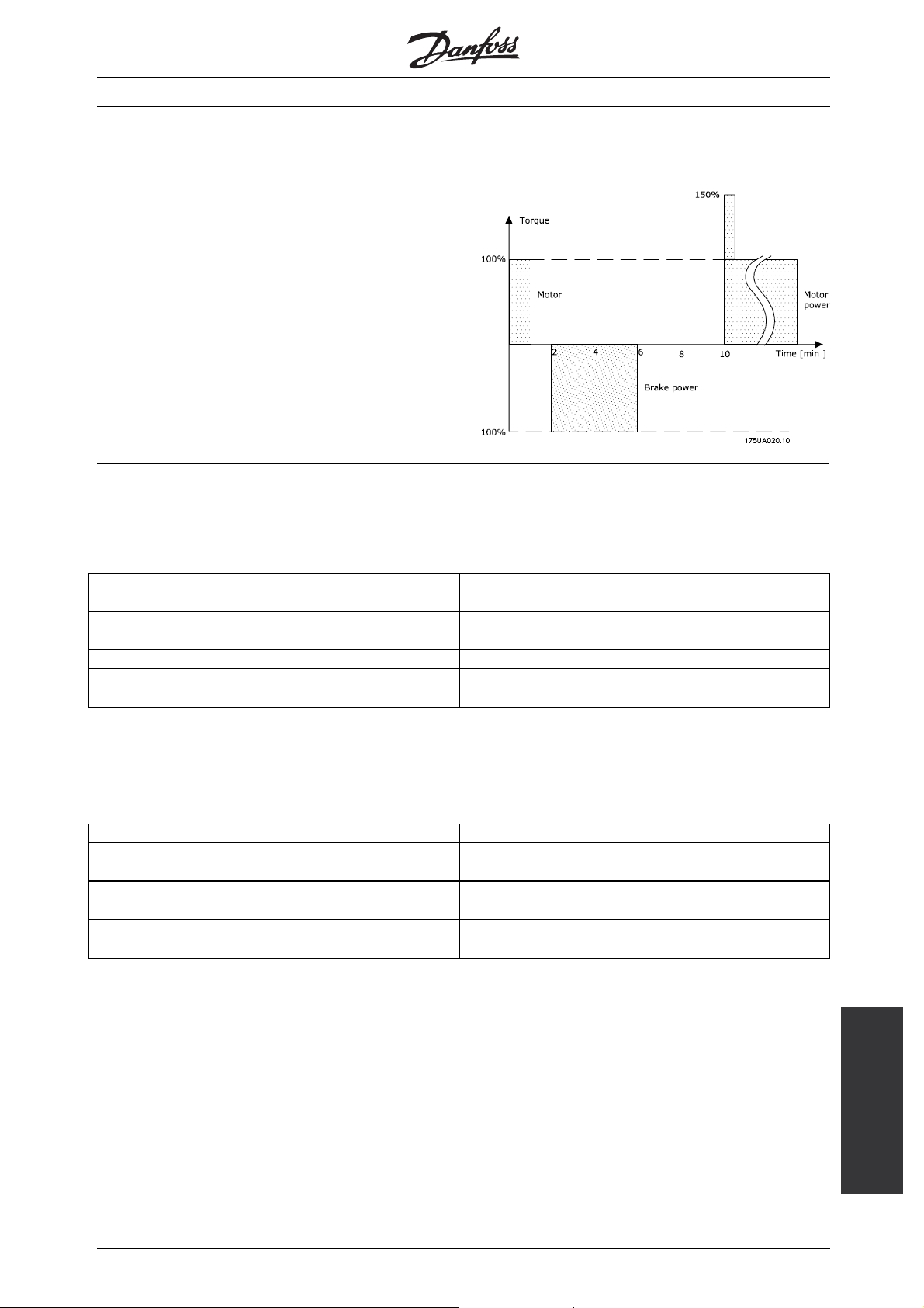
Fig. 1 shows the relation between the braking power
and the acceleration/braking of a conveyor belt. As can
be seen, the motor power during braking is negative,
since the torque on the motor shaft is negative. The
braking power, i.e. the power to be dissipated to the
brake resistor, corresponds almost to the negative
motor power, taking the losses in the motor and the
frequency converter into account. The example also
shows that the motor power is time-dependent.
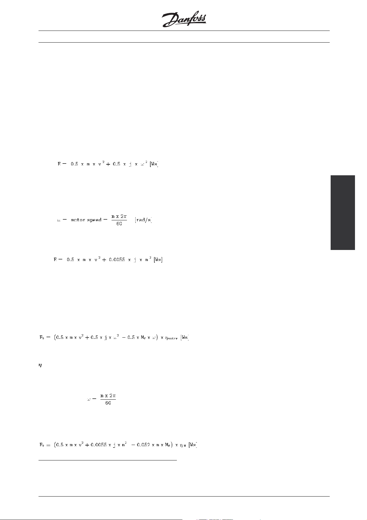
Kinetic energy (E) in conveyor belt + motor:
m = mass with linear movement [kg]
v = speed of mass with linear movement [m/s]
2
j = inertia of motor and gear box (kgm
]
VLT®2800/5000/5000 FLUX/FCD 300
This formula may also be expressed as follows:
However, not all of the energy is to be dissipated to
the brake resistor. The friction of the conveyor belt
andthepowerlossofthemotoralsocontributetothe
braking function. Consequently, the formula for energy
dissipation (E
) to the brake resistor is as follows:
b
Mf= Friction torque [Nm]
= Motor efficiency
M
When:
Examples
is inserted, the result is as follows:
MI.90.F1.02 - VLT is a registered Danfoss trademark
3
Page 4
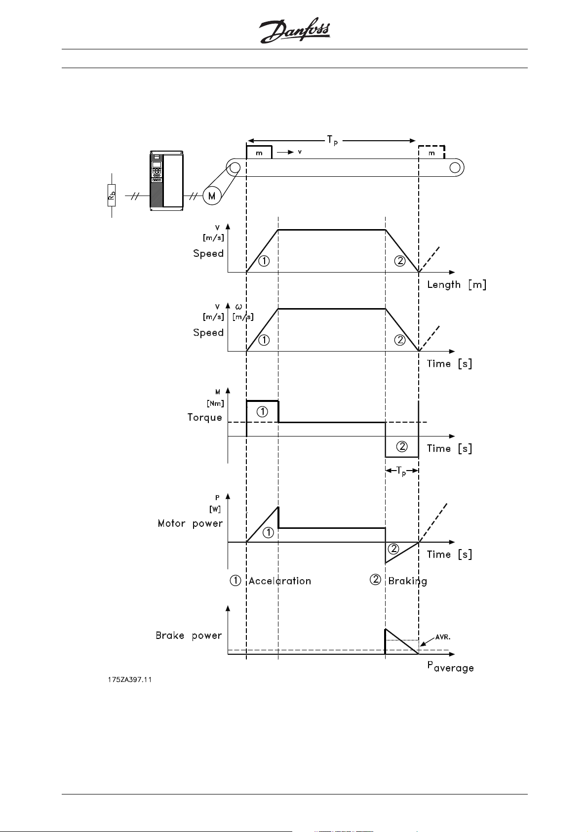
■Fig. 1
The relation between braking power and
acceleration/braking of a conveyor belt.
VLT®2800/5000/5000 FLUX/FCD 300
4
MI.90.F1.02 - VLT is a registered Danfoss trademark
Page 5
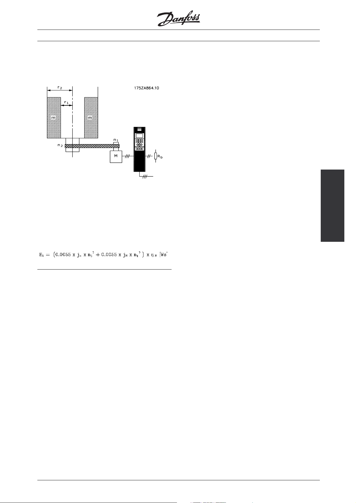
■Example 2 - Centrifuge
Another typical application in which braking
can be required on centrifuges. The weight of
the centrifuge content is m.
VLT®2800/5000/5000 FLUX/FCD 300
jC= centrifuge inertia =
2
2
+r
½xmx(r
j
= Gear motor inertia [kgm2]
M
= Gear motor efficiency
η
M
n
= max. motor speed [rpm]
1
= max. centrifuge speed [rpm]
n
2
1
)[kgm2]
2
Examples
MI.90.F1.02 - VLT is a registered Danfoss trademark
5
Page 6
■Brake setup
Fig. 2 shows a brake set-up using a
frequency converter.
The following sections use expressions and
abbreviations with respect to a brake set-up
that can be seen from fig. 2.
Fig. 2
VLT®2800/5000/5000 FLUX/FCD 300
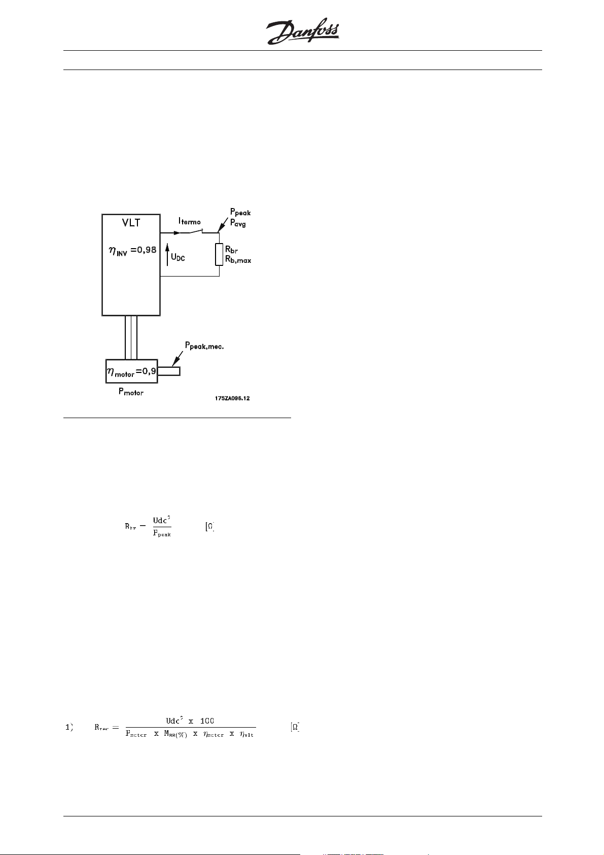
■Calculation of brake resistor values
To keep the VLT frequency converter from cutting out
for protection when the motor brakes, the resistor
values are to be selected on the basis of the peak
braking power and the intermediate circuit voltage:
As can be seen, the brake resistor depends on
the intermediate circuit voltage (Udc).
Udc is the voltage, where the brake is activated. For
values see further on in this instruction.
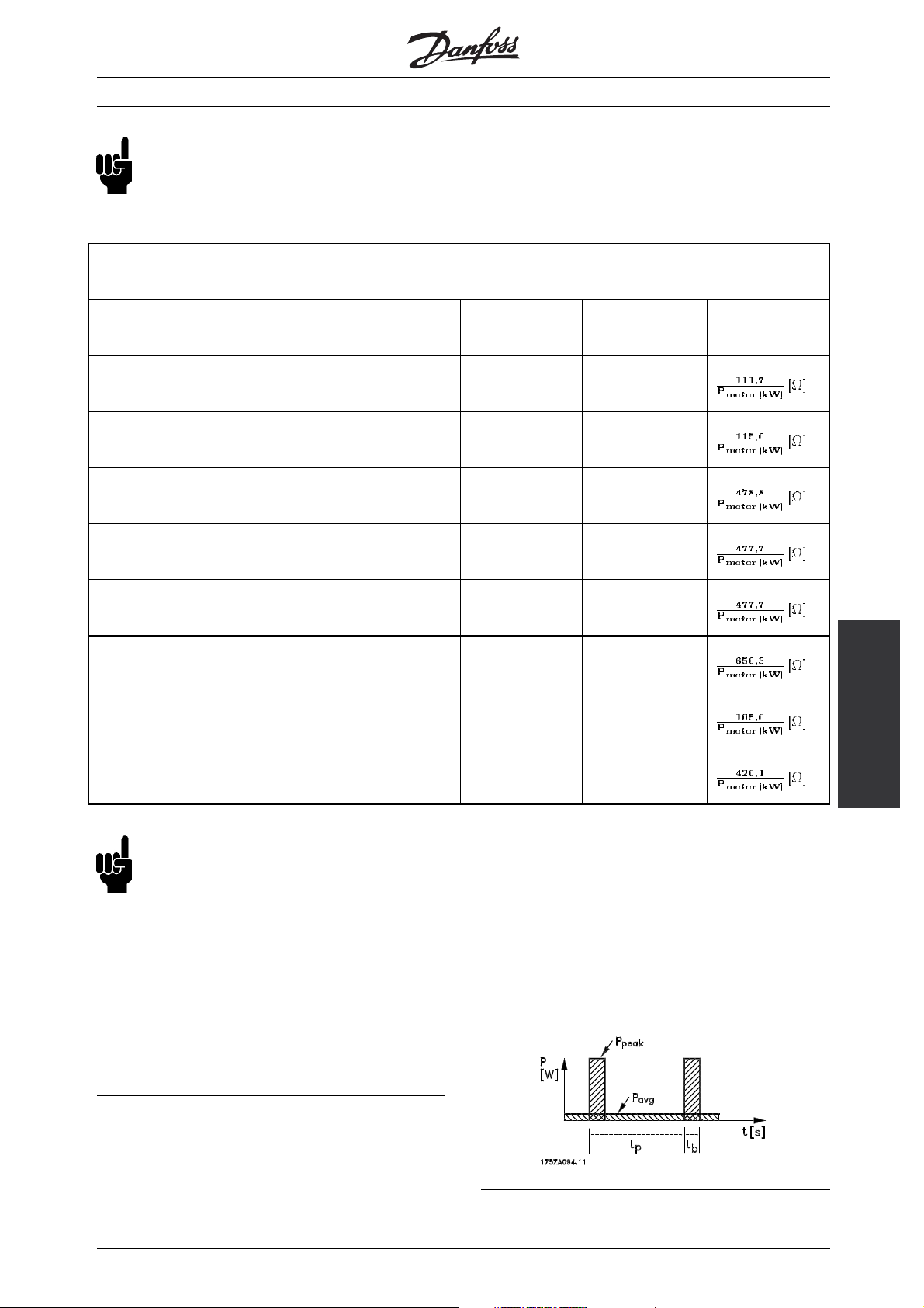
Another option is to use the brake resistor
recommended by Danfoss (Rrec). This guarantees
that the frequency converter is able to brake at the
highest braking torque (Mbr), i.e. 160% / 150% /
100%. See the tables further on in this instruction.
6
MI.90.F1.02 - VLT is a registered Danfoss trademark
Page 7
NB!:
Remember to check whether your brake resistor
is able to handle the intermediate voltage (Udc
for your specific drive can be found in the table
below) if you do not use Danfoss brake resistors.
VLT®2800/5000/5000 FLUX/FCD 300
ηηηη
VLT type Udc
is typically 0,9, while ηηηη
motor
is typically 0,98. R
vlt
can be expressed as follows:
rec
Max. Braking
torque
5001-5027 Process and FLUX / 200-240 Volt 397 Volt 160 %
5032-5052 Process and FLUX / 200-240 Volt 390 Volt 150 %
5001-5062, 5072 and 5102 Process and FlLUX /
380-500 Volt
822 Volt 160 %
5075, 5100 and 5125-5500 Process / 380-500 Volt 795 Volt 150 %
5075, 5100 and 5125-5500 FLUX / 380-500 Volt 795 Volt 100 %
5001-5250 Process / 550-600 Volt 958 Volt 160 %
2803-2840 / 200-240 Volt 385 Volt 160 %
R
=
rec
2805-2882 and FCD 303-335 / 380-480 Volt 770 Volt 160%
NB!:
Choose a brake resistor which is max. 10%
below the value recommended by Danfoss.
If a bigger brake resistor is selected, 160% /
150% / 100% braking torque cannot be obtained,
and there is a risk that the frequency converter
will cut out for protection.
Ifbrakingisonlye.g. at80%torque,itispossibleto
install a bigger brake resistor, the size of which can
be calculated using the formula R
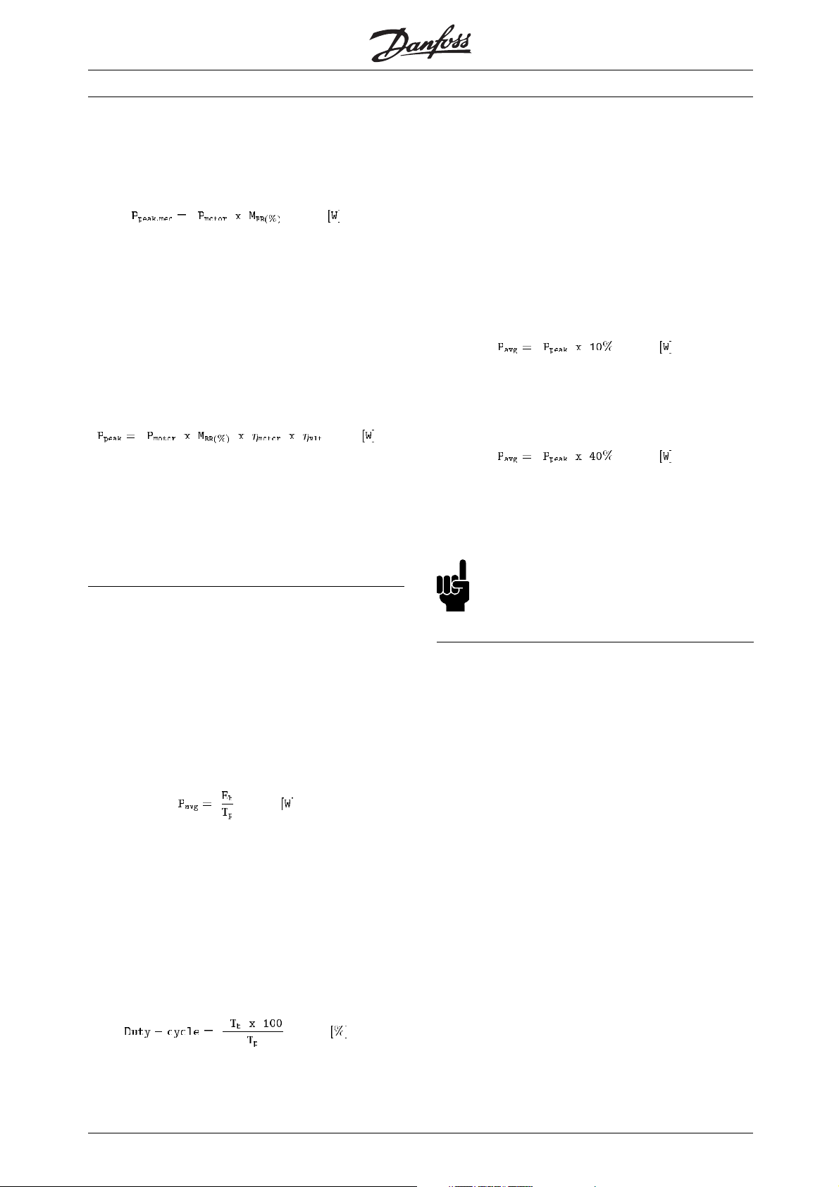
■Calculation of braking power
When calculating the braking power, it is to be ensured
that the brake resistor is able to handle the average
power as well as the peak power. The average power is
, no. 1.
rec
determined by the process period time, i.e. the length
of the braking time in relation to the process period time.
The peak power is determined by the braking torque,
which means that as braking progresses, the brake
resistor must be able to dissipate the energy input.
Fig. 3 shows the relation between the average
power and the peak power.
Fig. 3
brake resistor
Calculation of the
MI.90.F1.02 - VLT is a registered Danfoss trademark
7
Page 8
VLT®2800/5000/5000 FLUX/FCD 300
■Calculation of the brake resistor peak power
P
peak, mec
is the peak power by which the motor brakes
on the motor shaft. It is calculated as follows:
P
is the name used for the braking power dissipated
peak
to the brake resistor when the motor brakes.
is lower than P
P
peak
peak,mec
since the power
is reduced by the efficiencies of the motor and
the VLT frequency converter.
The peak power is calculated as follows:
If the brake resistor recommended by Danfoss is
selected (R
) on the basis of the tables further
rec
on in this instruction, the brake resistor will be
certain to provide a braking torque of 160% /
150% / 100% on the motor shaft.
■Calculation of the brake resistor average power
The average power is determined by the process
period time, i.e. the length of the braking time in
relation to the process period time.
Danfoss offers brake resistors with a duty-cycle of
max. 10% and 40%, respectively (some drives are
only available with a duty-cycle of max. 10%). If
a 10% duty-cycle is applied, the brake resistors
are able to absorb Ppeak for 10% of the period
time. The remaining 90% of the period time will
be used on deflecting excess heat.
The average power with 10% duty-cycle can
be calculated as follows:
The average power with 40% duty-cycle can
be calculated as follows:
The calculations apply to intermittent braking using a
period time of 120/300 seconds (to define whether it is
120 or 300 seconds. Please see the tables further on).
NB!:
Longer time than the specified intermittent
braking period time may result in overheating
of the resistor.
If the amount of kinetic energy (Eb) transferred to
the resistor in each braking sequence (see examples
1 and 2) is known, the average power of the
resistor can be calculated as follows:
Tp= period time in seconds (see drawing on page 3).
If the amount of kinetic energy transferred to the
resistor in each braking sequence is not known, the
average power can be calculated on the basis of the
process period time and the braking time.
The duty-cycle for the braking sequence is
calculated as follows:
Tp= process period time in seconds.
T
= braking time in seconds.
b
8
MI.90.F1.02 - VLT is a registered Danfoss trademark
Page 9
VLT®2800/5000/5000 FLUX/FCD 300
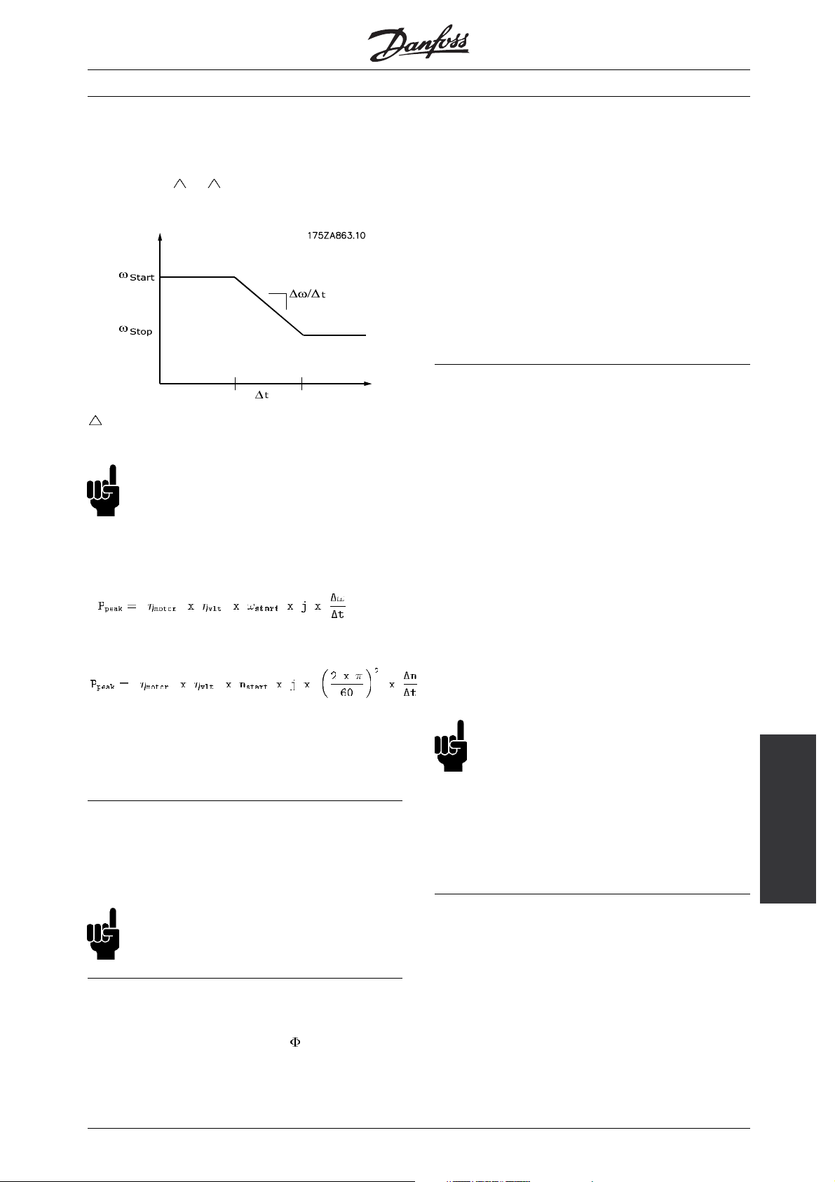
■Braking of inertia
In the case of braking of high inertia values on the
motor shaft, the brake resistor values can be based
on the inertia,
ω, t. See fig. 4.
Fig. 4
t is determined by the ramp-down time
in parameter 208.
NB!:
The ramp-down time goes from the rated motor
frequency in parameter 104 to 0 Hz.
P
can be calculated as:
peak
Since the electrical resistance of the rotor cage is very
low, even small induced voltages can create a high
rotor current. This current will produce a strong braking
effect on the bars and hence on the rotor. As the speed
falls, the frequency of the induced voltage falls and with
it the inductive impedance. The ohmic resistance of the
rotor gradually becomes dominant and so increases
the braking effect as the speed comes down. The
braking torque generated falls away steeply just before
standstill and finally ceases when there is no further
movement. Direct current injection braking is therefore
not suitable for actually holding a load at rest.
■AC-braking VLT 2800 and FCD 300
WhenthemotoractsasabraketheDC-linkvoltagewill
increase because energy is fed back to the DC-link. The
principle in AC-brake is to increase the magnetisation
during the braking and thereby increase the thermal
losses of the motor. Using par. 144 in VLT 2800 and
FCD 300 it is possible to adjust the size of the generator
torque that can be applied to the motor without the
intermediate circuit voltage exceeding the warning level.
The braking torque depends on the speed. With
the AC-brake function enabled and parameter 144
= 1,3 (factory setting) it is possible to brake with
about 50 % of rated torque below 2/3 of rated speed
and with about 25 % at rated speed. The function
is not working at low speed (below 1/3 of nominal
motor speed). It is only possible to run for about 30
seconds with parameter 144 greater than 1.2.
jistheinertiaofthemotorshaft.
Calculate the value on the brake resistor as described
under the preceding paragraphs.
■Continuous braking
For continuous braking, select a brake resistor in
which the constant braking power does not exceed
the average power P
of the brake resistor.
avg
NB!:
Please contact your Danfoss distributor
for further information.
■D.C. injection braking
If the three-phase winding of the stator is fed with direct
current, a stationary magnetic field
will be set up in
the stator bore causing a voltage to be induced in the
bars of the cage rotor as long as the rotor is in motion.
NB!:
If the value in parameter 144 is increased,
the motor current will simultaneously increase
significantly when generator loa
ds are applied.
The parameter should therefore only be changed if
it is guaranteed during measurement that the motor
current in all operating situa
tions will never exceed the
maximum permitted current in the motor. Please note:
The current can not be read out from the display.
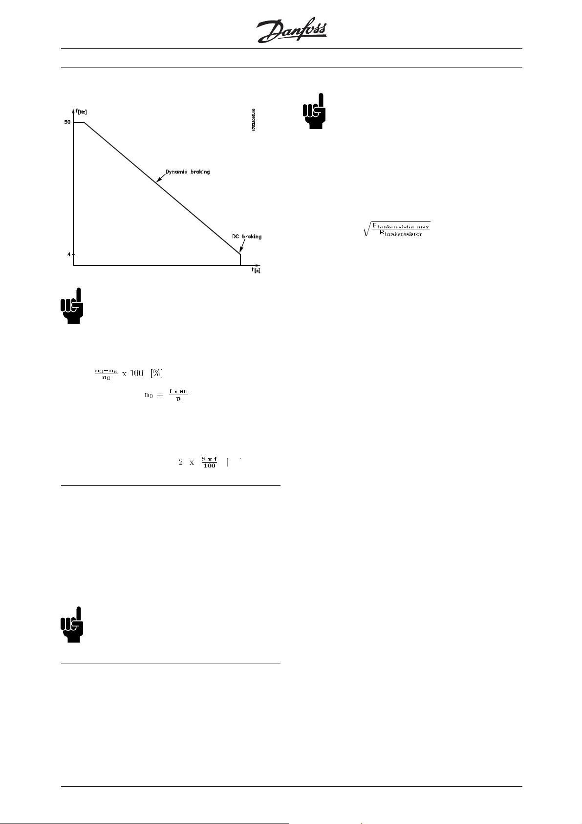
■Optimum braking
Dynamic braking is useful from max. speed down to a
certain frequency. Below this frequency DC braking
is to be applied as required. The most efficient way
of doing this is to use a combination of dynamic
and DC braking. See fig. 5. The parameters can
be found further on in this instruction.
Braking
MI.90.F1.02 - VLT is a registered Danfoss trademark
9
Page 10
VLT®2800/5000/5000 FLUX/FCD 300
Fig. 5
NB!:
When changing from dynamic to DC braking,
there will be a short period (2-6 milliseconds)
with very low braking torque.
How to calculate optimum DC-brake cut in frequency:
Slip S=
NB!:
The brake resistor is to be fitted on a
non-flammable material.
For protection of the installation, a thermal relay
should be fitted that cuts off the frequency converter
if the brake current becomes too high.
Calculate the brake current setting of the
thermal relay as follows:
Itherm relay =
Rbris the current brake resistor value calculated in the
section on "Calculation of brake resistor values". Fig.
6 shows an installation with a thermal relay.
The brake current setting of thermal relay for
Danfoss brake resistors can be found in tables
further on in this instruction.
Synchronous speed [1/min]
f = frequency
p=no. ofpolepairs
= speed of the rotor
n
n
DC-brake cut in frequency =
Hz
■Brake cable
Max. length [m]: 20 m
The connection cable to the brake resistor is t
screened/armoured. Connect the screen/armouring
to the conductive back plate at the VLT frequency
converter and to the brake resistor metal c
by means of cable clamps.
NB!:
If Danfoss brake resistors are not used,
make sure that the brake resistors used
are induction-free.
obe
abinet
■Protective functions during installation
When installing a brake resistor
, every measure
should be taken to avoid the risk of overloading,
since a fire hazard may arise owing to the heat
generated in the heat resistor
.
10
MI.90.F1.02 - VLT is a registered Danfoss trademark
Page 11

Fig. 6
VLT®2800/5000/5000 FLUX/FCD 300
Some of the Danfoss Brakeresistors contain a thermal
switch (see tables further on in this instruction). This
switch is NC (normally closed) and can be used e.g.
coasting stop reverse between terminal 12 and 27. The
drive will then coast, if the thermal switch is opened.
NB!:
The thermal switch is not a protective
device. For protection, use a thermal
switch as shown in fig. 6.
■Description of VLT 5000 brake
Danfoss VLT 5000 Series enables activation of an
integral brake monitor to guarantee that the braking
power does not exceed a given limit.
The power is calculated on the basis of the resistor
ohm value (parameter 401), the intermediate
circuit voltage and the resistor running time. For
further information, see page 10.
NB!:
The brake power monitoring system is not
a protective device. For protection, use a
thermal switch as shown in fig. 6.
Via the digital/relay outputs, it is possible to get a
status message concerning the brake, e.g. indicating
brake faults. Furthermore, VLT 5000 Series features an
integral function to check whether the brake resistor
has been connected/is intact at the time of power-up.
Additionally, the brake is protected against
short-circuiting by the brake resistor. The brake
circuit is not earthing proof.
Braking
MI.90.F1.02 - VLT is a registered Danfoss trademark
11
Page 12
VLT®2800/5000/5000 FLUX/FCD 300
■VLT 5000 Process parameters
The following is a list of parameters for the VLT 5000
Process Series which are important or relevant for
thedynamicbrakeandtheDCbrake.
Parameter Suggestion of settings
125 DC braking current Depends on the desired braking torque
126 DC braking time Set the desired DC braking time
127 DC brake cut-in frequency Set the desired DC brake cut-in frequency
222 Torque limit for generating operation 160 %
319 Output (terminal 42) Brake no warning,
Brake ready no fault or
Brake fault
321 Output (terminal 45) Same as 319
323 Output (relay 01) Same as 319
326 Output (relay 4) Same as 319
400 Brake function/overvoltage control Resistor brake
401 Brake resistor, ohm Depends on the unit, see the tables further on in this
instruction
402 Brake power limit, kW Depends on the unit, see the tables further on in this
instruction
403 Power monitoring Warning or trip
404 Brake check Warning or trip
■VLT 5000 FLUX parameters
The following is a list of parameters for the VLT
5000 FLUX Series which are important or relevant
for the dynamic brake and the DC brake.
Parameter Suggestion of settings
125 DC braking current Depends on the desired braking torque
126 DC braking time Set the desired DC braking time
127 DC brake cut-in frequency Set the desired DC brake cut-in frequency
222 Torque limit for generating operation 160 %
323 Output (relay 01) Brake no warning,
Brake ready no fault or
Brake fault
326 Output (relay 4) Same as 323
341 Output (terminal 46) Same as 323
355 Output (terminal 26) Same as 323
400 Brake function/overvoltage control Resistor brake
401 Brake resistor, ohm Depends on the unit, see the tables further on in this
instruction
402 Brake power limit, kW Depends on the unit, see the tables further on in this
instruction
403 Power monitoring Warning or trip
404 Brake check Warning or trip
12
MI.90.F1.02 - VLT is a registered Danfoss trademark
Page 13
The sizes VLT 5125 and 5150 are equipped with
a better dynamic brake performance compared to
the same sizes in VLT 5000 Process.
Itispossibletobrake4minout10mininatotal
cycle (Duty type S% 40% EN 60034-1)
■VLT 2800 parameters
The following is a list of parameters for the VLT
2800 Series which are important or relevant for the
dynamic brake and the DC brake.
VLT®2800/5000/5000 FLUX/FCD 300
VLT 5125 FLUX and VLT 5150 FLUX
Parameter Suggestion of settings
126 DC braking time Set the desired DC braking time
127 DC brake engaging frequency Set the desired DC brake engaging frequency
132 DC brake voltage Depends on the desired braking torque
400 Brake function Resistor or AC brake
456 Brake voltage reduce 0 should only be used if there are problems with
overvoltage in the intermediate circuit
■FCD 300 parameters
The following is a list of parameters for the VLT
FCD 300 Series which are important or relevant for
thedynamicbrakeandtheDCbrake.
Parameter Suggestion of settings
126 DC braking time Set the desired DC braking time
127 DC brake engaging frequency Set the desired DC brake engaging frequency
132 DC brake voltage Depends on the desired braking torque
400 Brake function Resistor or AC brake
456 Brake voltage reduce 0 should only be used if there are problems with
overvoltage in the intermediate circuit
MI.90.F1.02 - VLT is a registered Danfoss trademark
Programming
13
Page 14

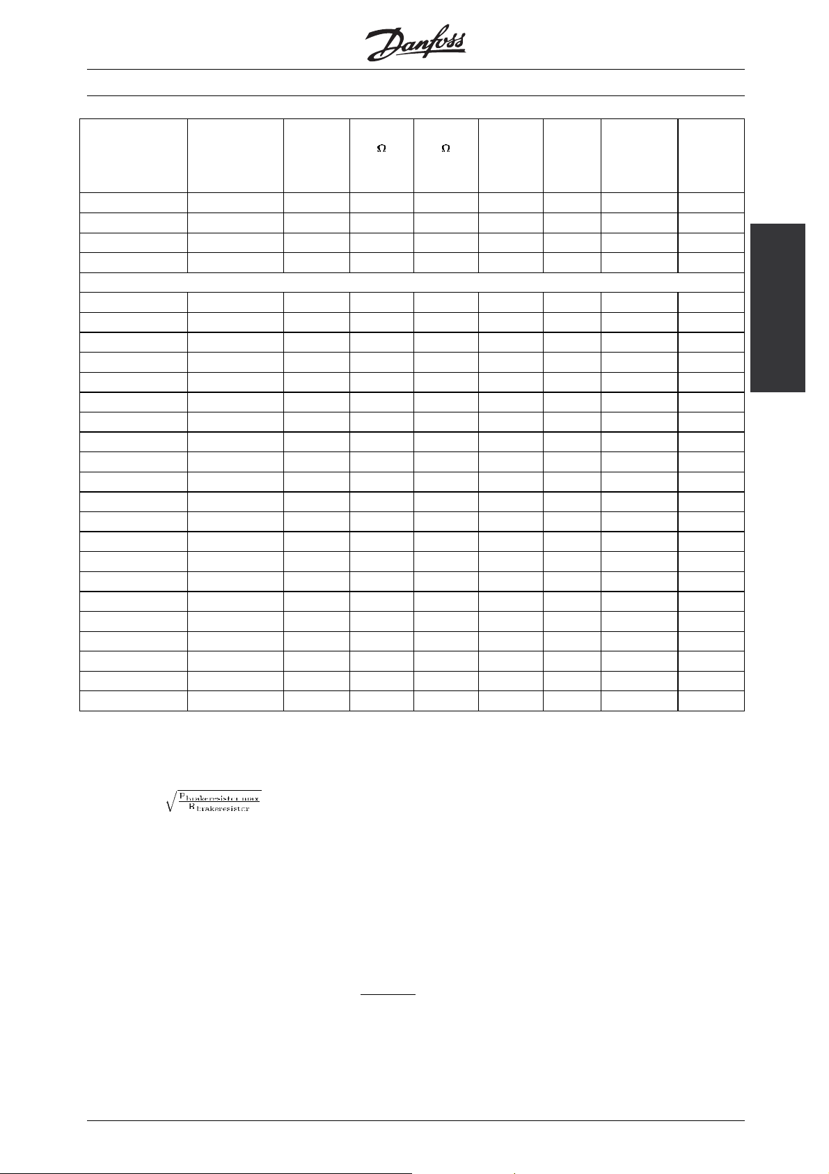
■Brake resistor for VLT 5001-5500 10% duty-cycle
data and codenumber
VLT®2800/5000/5000 FLUX/FCD 300
VLT type
P=Process
F=FLUX
5001 P, F (200V) 120 0,75 130 145 0,065 0,7 1820 1,5******
5002 P, F (200V) 120 1,1 81 90 0,095 1,0 1821 1,5******
5003 P, F (200V) 120 1,5 58 65 0,25 2,0 1822 1,5******
5004 P, F (200V) 120 2,2 45 50 0,285 2,4 1823 1,5******
5005 P, F (200V) 120 3,0 31 35 0,43 2,5 1824 1,5******
5006 P, F (200V) 120 4,0 22 25 0,8 5,7 1825 1,5******
5008 P, F (200V) 120 5,5 18 20 1,0 7,1 1826 1,5******
5011 P, F (200V) 120 7,5 13 15 2,0 11 1827 1,5******
5016 P, F (200V) 120 11,0 9,0 10 2,8 17 1828 2,5******
5022 P, F (200V) 120 15,0 6,3 7,0 4,0 24 1829 4******
5027 P, F (200V) 120 18,5 5,2 6,0 4,8 28 1830 4******
5032 P, F (200V) 300 22,0 4,2 4,7 6,0 36 1954 10******
5042 P, F (200V) 300 30,0 3,0 3,3 8,0 49 1955 10******
5052 P, F (200V) 300 37,0 2,4 2,7 10,0 61 1956 16******
5001 P, F (500V) 120 0,75 557 620 0,065 0,3 1840 1,5******
5002 P, F (500V) 120 1,1 382 425 0,095 0,5 1841 1,5******
5003 P, F (500V) 120 1,5 279 310 0,25 0,9 1842 1,5******
5004 P, F (500V) 120 2,2 189 210 0,285 1,2 1843 1,5******
5005 P, F (500V) 120 3,0 135 150 0,43 1,7 1844 1,5******
5006 P, F (500V) 120 4,0 99 110 0,6 2,3 1845 1,5******
5008 P, F (500V) 120 5,5 72 80 0,85 3,3 1846 1,5******
5011 P, F (500V) 120 7,5 58,5 65 1,0 3,9 1847 1,5******
5016 P, F (500V) 120 11,0 36 40 2,0 7,1 1848 1,5******
5022 P, F (500V) 120 15,0 27 30 2,8 9,7 1849 1,5******
5027 P, F (500V) 120 18,5 22 25 3,5 12 1850 1,5******
5032 P, F (500V) 120 22,0 18 20 4,0 14 1851 1,5******
5042 P, F (500V) 120 30,0 13 15 4,8 18 1852 2,5******
5052 P, F (500V) 120 37,0 10,8 12 5,5 21 1853 2,5******
5060 P, F (500V)**** 300 45,0 7,0 7,8 12 39 N.A. 10******
5062 P, F (500V) 120 45,0 9,8 9,8 15 39 2008 10******
5072 P, F (500V) 120 55,0 7,3 7,3 13 42 0069 10******
5075 P (500V)* 300 55,0 5,1 5,7 14 50 1958 10******
5075 F (500V) * 600******* 55,0 5,1 5,7 21 61 0076 16******
5100 P (500V)** 300 75,0 4,2 4,7 18 62 1959 16******
5100 F (500V)** 600******* 75,0 4,2 4,7 29 79 0077 25******
5102 P, F (500V) 120 75,0 5,7 6,33 15 49 0067 10******
5125 P (500V) 300 90,0 3,4 3,8 22 76 1960 25******
5125 F (500V) 600******* 90,0 3,4 3,8 36 97 0078 35******
5150 P (500V) 300 110 2,9 3,2 27 92 1961 35******
5150 F (500V) 600******* 110 2,9 3,2 42 115 0079 50******
5200 P, F (500V) 300 132 2,3 2,6 32 111 1962 50******
5250 P, F (500V) 300 160 1,9 2,1 39 136 1963 70******
Intermittent
braking period
time
[seconds]
P
motor
[kW]
R
[ ]
min
R
[ ]
rec
Pb,max
[kW]
Therm.
relay
[Amp]
Code
number
175Uxxxx
Cable
cross
section
[mm
2
]
14
MI.90.F1.02 - VLT is a registered Danfoss trademark
Page 15
VLT®2800/5000/5000 FLUX/FCD 300
VLT type
P=Process
F=FLUX
5300 P, F (500V) 300 200 3,14 3,3 56 130 2 x 1061*** 50******
5350 P, F (500V) 300 250 2,47 2,6 72 166 2 x 1062*** 70******
5450 P, F (500V) 300 315 2,19 2,3 90 198 2 x 1063*** 95******
5500 P, F (500V) 300 355 2,00 2,1 100 218 2 x 1064*** 120******
5001 P (600V) 120 0,75 797 797 R.d. ***** N.A.
5002 P (600V) 120 1,1 534 534 R.d. ***** N.A.
5003 P (600V) 120 1,5 398 398 R.d. ***** N.A.
5004 P (600V) 120 2,2 267 267 R.d. ***** N.A.
5005 P (600V) 120 3,0 199 199 R.d. ***** N.A.
5006 P (600V) 120 4,0 149 149 R.d. ***** N.A.
5008 P (600V) 120 5,5 107 107 R.d. ***** N.A.
5011 P (600V) 120 7,5 80 80 R.d. ***** N.A.
5016 P (600V) 120 11,0 53,4 53,4 R.d. ***** N.A.
5022 P (600V) 120 15,0 39,8 39,8 R.d. ***** N.A.
5027 P (600V) 120 18,5 32,0 32,0 R.d. ***** N.A.
5032 P (600V) 120 22,0 26,7 26,7 R.d. ***** N.A.
5042 P (600V) 120 30,0 19,9 19,9 R.d. ***** N.A.
5052 P (600V) 120 37,0 16,0 16,0 R.d. ***** N.A.
5062 P (600V) 120 45,0 13,3 13,3 R.d. ***** N.A.
5075 P (600V) 300 55,0 11,0 11,0 R.d. ***** N.A.
5100 P (600V) 300 75,0 8,2 8,2 R.d. ***** N.A.
5125 P (600V) 300 90,0 6,8 6,8 R.d. ***** N.A.
5150 P (600V) 300 110 5,6 5,6 R.d. ***** N.A.
5200 P (600V) 300 132 4,3 4,3 R.d. ***** N.A.
5250 P (600V) 300 160 3,3 3,3 R.d. ***** N.A.
Intermittent
braking period
time
[seconds]
P
motor
[kW]
R
[ ]
min
R
[ ]
rec
Pb,max
[kW]
Therm.
relay
[Amp]
Code
number
175Uxxxx
Cable
cross
section
[mm
2
]
overview
Brake resistor
*to be replaced by VLT 5072
**to be replaced by VLT 5102
***Order 2 pcs.
****Replaced by VLT 5062
*****Itherm relay =
******Always observe national and local regulations
******* Please observe drawing at VLT 5000 FLUX parameters
P
motor
R
min
R
rec
P
b, max
: Rated motor size for VLT type
: Minimum permissible brake resistor
: Recommended brake resistor (Danfoss)
: Brake resistor rated power as stated by supplier
Therm. relay : Brake current setting of thermal relay
Code number : Order numbers for Danfoss brake resistors
Cable cross section : Recommended m
inimum value based upon PVC insulated cober cable, 30
degree Celsius ambient temperature with normal heat dissipation
R.d. : Resistor dependent
MI.90.F1.02 - VLT is a registered Danfoss trademark
15
Page 16

■Brake resistor for VLT 5001-5102 40% duty-cycle
data and codenumber
VLT®2800/5000/5000 FLUX/FCD 300
VLT type
P=Process
F=FLUX
5001 P, F (200V) 120 0,75 130 145 0,26 1,3 1920 1,5**
5002 P, F (200V) 120 1,1 81 90 0,43 2,2 1921 1,5**
5003 P, F (200V) 120 1,5 58 65 0,8 3,5 1922 1,5**
5004 P, F (200V) 120 2,2 45 50 1,0 4,5 1923 1,5**
5005 P, F (200V) 120 3,0 31 35 1,35 6,2 1924 1,5**
5006 P, F (200V) 120 4,0 22 25 3,0 11,0 1925 1,5**
5008 P, F (200V) 120 5,5 18 20 3,5 13,0 1926 1,5**
5011 P, F (200V) 120 7,5 13 15 5,0 18,0 1927 2,5**
5016 P, F (200V) 120 11,0 9 10 9,0 30,0 1928 10**
5022 P, F (200V) 120 15,0 6,5 7 10,0 38,0 1929 16**
5027 P, F (200V) 120 18,5 5,2 6 12,7 46,0 1930 16**
5001 P, F (500V) 120 0,75 557 620 0,26 0,6 1940 1,5**
5002 P, F (500V) 120 1,1 382 425 0,43 1,0 1941 1,5**
5003 P, F (500V) 120 1,5 279 310 0,8 1,6 1942 1,5**
5004 P, F (500V) 120 2,2 189 210 1,35 2,5 1943 1,5**
5005 P, F (500V) 120 3,0 135 150 2,0 3,7 1944 1,5**
5006 P, F (500V) 120 4,0 99 110 2,4 4,7 1945 1,5**
5008 P, F (500V) 120 5,5 72 80 3,0 6,1 1946 1,5**
5011 P, F (500V) 120 7,5 59 65 4,5 8,3 1947 1,5**
5016 P, F (500V) 120 11,0 36 40 5,0 11 1948 1,5**
5022 P, F (500V) 120 15,0 27 30 9,3 18 1949 2,5**
5027 P, F (500V) 120 18,5 22 25 12,7 23 1950 4**
5032 P, F (500V) 120 22,0 18 20 13,0 25 1951 4**
5042 P, F (500V) 120 30,0 14 15 15,6 32 1952 10**
5052 P, F (500V) 120 37,0 10 12 19,0 40 1953 16**
5062 P, F (500V) 120 45,0 9,8 9,8 38,0 62 2007 16**
5072 P, F (500V) 120 55,0 7,3 7,3 38,0 72 0068 25**
5102 P, F (500V) 120 75,0 5,7 6,0 45,0 87 0066 25**
5125 F (500V) 600*** 90,0 3,4 3,8 75 140 2 x 0072 2x70**
5150 F (500V) 600*** 110 2,9 3,2 90 168 2 x 0073 2x70**
Intermittent
braking period
time [seconds]
P
motor
[kW]
R
[ ]
min
R
[ ]
rec
P
b, max
[kW]
Therm.re-
lay
[Amp]
Code
number
175Uxxxx
Cable
cross
section
2
[mm
]
5001 P (600V) 120 0,75 797 797 R.d. * N.A.
5002 P (600V) 120 1,1 534 534 R.d. * N.A.
5003 P (600V) 120 1,5 398 398 R.d. * N.A.
5004 P (600V) 120 2,2 267 267 R.d. * N.A.
5005 P (600V) 120 3,0 199 199 R.d. * N.A.
5006 P (600V) 120 4,0 149 149 R.d. * N.A.
5008 P (600V) 120 5,5 107 107 R.d. * N.A.
5011 P (600V) 120 7,5 80 80 R.d. * N.A.
5016 P (600V) 120 11,0 53,4 53,4 R.d. * N.A.
5022 P (600V) 120 15,0 39,8 39,8 R.d. * N.A.
5027 P (600V) 120 18,5 32,0 32,0 R.d. * N.A.
16
MI.90.F1.02 - VLT is a registered Danfoss trademark
Page 17

VLT®2800/5000/5000 FLUX/FCD 300
VLT type
P=Process
F=FLUX
5032 P (600V) 120 22,0 26,7 26,7 R.d. * N.A.
5042 P (600V) 120 30,0 19,9 19,9 R.d. * N.A.
5052 P (600V) 120 37,0 16,0 16,0 R.d. * N.A.
5062 P (600V) 120 45,0 13,3 13,3 R.d. * N.A.
*Itherm relay =
**Always observe national and local regulations
*** Please observe drawing at VLT 5000 Flux parameters
P
motor
R
min
R
rec
P
b, max
Intermittent
braking period
time [seconds]
: Rated motor size for VLT type
: Minimum permissible brake resistor
: Recommended brake resistor (Danfoss)
: Brake resistor rated power as stated by supplier
P
motor
[kW]
R
[ ]
min
R
[ ]
rec
P
b, max
[kW]
Therm.re-
lay
[Amp]
number
175Uxxxx
Therm. relay : Brake current setting of thermal relay
Code number : Order numbers for Danfoss brake resistors
Cable cross section : Recommended m
inimum value based upon PVC insulated cober cable, 30
degree Celsius ambient temperature with normal heat dissipation
R.d. : Resistor dependent
Code
Cable
cross
section
2
[mm
]
overview
Brake resistor
■Brake resistor for VLT 2803-2882 duty-cycle
40% data and codenumber
VLT type Intermit-
tent brak-
ing period
time
[seconds]
2803 (200V) 120 0,37 297 330 0,16 0,7 1900* 1,5**
2805 (200V) 120 0,55 198 220 0,25 1,1 1901* 1,5**
2807 (200V) 120 0,75 135 150 0,32 1,5 1902* 1,5**
2811 (200V) 120 1,1 99 110 0,45 2,0 1975* 1,5**
2815 (200V) 120 1,5 74 82 0,85 3,2 1903* 1,5**
2822 (200V) 120 2,2 50 56 1,00 4,2 1904* 1,5**
2840 (200V) 120 3,7 22 25 3,00 11,0 1925 1,5**
2805 (400V) 120 0,55 747 830 0,45 0,7 1976* 1,5**
2807 (400V) 120 0,75 558 620 0,32 0,7 1910* 1,5**
2811 (400V) 120 1,1 387 430 0,85 1,4 1911* 1,5**
2815 (400V) 120 1,5 297 330 0,85 1,6 1912* 1,5**
2822 (400V) 120 2,2 198 220 1,00 2,1 1913* 1,5**
2830 (400V) 120 3,0 135 150 1,35 3,0 1914* 1,5**
2840 (400V) 120 4,0 99 110 1,60 3,8 1979* 1,5**
2855 (400V) 120 5,5 80 80 2,00 5,0 1977* 1,5**
2875 (400V) 120 7,5 56 56 3,00 6,8 1978* 1,5**
2880 (400V) 120 11 40 40 5,00 11,2 1997* 1,5**
2881 (400V) 120 15 30 30 10,0 18,3 1998 2,5**
2882 (400V) 120 18,5 25 25 13,0 22,8 1999 4**
P
motor
[kW]
R
min
[ ]
R
[ ]
rec
P
b, max
[kW]
Therm.re-
lay
[Amp]
Code
number
175Uxxxx
Cable
cross
section
2
[mm
]
*With KLIXON switch
**Always observe national and local regulations
MI.90.F1.02 - VLT is a registered Danfoss trademark
17
Page 18

■Brake resistor for VLT FCD 303-335 duty-cycle
40% data and codenumber
VLT®2800/5000/5000 FLUX/FCD 300
VLT type Intermit-
tent brak-
ing period
time
[seconds]
303 (400 V) 120 0,37 520 830 0,45 0,7 1976 1,5*
305 (400 V) 120 0,55 405 830 0,45 0,7 1976 1,5*
307 (400 V) 120 0,75 331 620 0,32 0,7 1910 1,5*
311 (400 V) 120 1,1 243 430 0,85 1,4 1911 1,5*
315 (400 V) 120 1,5 197 330 0,85 1,6 1912 1,5*
322 (400 V) 120 2,2 140 220 1,00 2,1 1913 1,5*
330 (400 V) 120 3,0 104 150 1,35 3,0 1914 1,5*
335 (400 V) 120 3,3 104 150 1,35 3,0 1914 1,5*
*Always observe national and local regulations
P
motor
R
min
R
rec
P
b, max
P
motor
[kW]
R
min
[ ]
R
[ ]
rec
P
b, max
[kW]
: Rated motor size for VLT type
: Minimum permissible brake resistor
: Recommended brake resistor (Danfoss)
: Brake resistor rated power as stated by supplier
Therm.re-
lay
[Amp]
Code
number
175Uxxxx
Therm. relay : Brake current setting of thermal relay
Code number : Order numbers for Danfoss brake resistors
Cable cross section : Recommended m
inimum value based upon PVC insulated cober cable, 30
degree Celsius ambient temperature with normal heat dissipation
Cable
cross
section
2
[mm
]
18
MI.90.F1.02 - VLT is a registered Danfoss trademark
Page 19

■Brake resistor for VLT 5001-5500 10% duty-cycle
cablegland, weight and drawing no.
VLT®2800/5000/5000 FLUX/FCD 300
VLT type
P=Process
F=FLUX
5001 P, F (200V) PG 9 1,1 1820 1
5002 P, F (200V) PG 9 1,1 1821 1
5003 P, F (200V) PG 9 2,1 1822 3
5004 P, F (200V) PG 9 2,1 1823 3
5005 P, F (200V) PG 9 2,2 1824 4
5006 P, F (200V) PG 9 3,0 1825 6
5008 P, F (200V) PG 9 3,5 1826 7
5011 P, F (200V) PG 16 5,8 1827 9
5016 P, F (200V) PG 21 13,5 1828 12
5022 P, F (200V) PG 21 15,0 1829 12
5027 P, F (200V) PG 21 16,5 1830 12
5032 P, F (200V) PG 21 19,0 1954 12
5042 P, F (200V) PG 21 20,0 1955 13
5052 P, F (200V) PG 21 32,0 1956 14
5001 P, F (500V) PG 9 1,1 1840 1
5002 P, F (500V) PG 9 1,2 1841 2
5003 P, F (500V) PG 9 2,1 1842 3
5004 P, F (500V) PG 9 2,1 1843 3
5005 P, F (500V) PG 9 2,2 1844 4
5006 P, F (500V) PG 9 2,4 1845 5
5008 P, F (500V) PG 9 3,0 1846 6
5011 P, F (500V) PG 9 3,5 1847 7
5016 P, F (500V) PG 16 5,8 1848 9
5022 P, F (500V) PG 16 13,5 1849 12
5027 P, F (500V) PG 16 15,0 1850 12
5032 P, F (500V) PG 16 15,0 1851 12
5042 P, F (500V) PG 21 16,5 1852 12
5052 P, F (500V) PG 21 19,0 1853 12
5062 P, F (500V) PG 21 36,0 2008 15
5072 P, F (500V) PG 21 40,0 0069 15
5075 P (500V) PG 21 49,0 1958 15
5075 F (500V) PG 29 65,0 0076 17
5100 P (500V) PG 21 52,0 1959 15
5100 F (500V) PG 36 67,0 0077 17
5102 P, F (500V) PG 21 40,0 0067 15
5125 P (500V) PG 29 56,0 1960 16
5125 F (500V) PG 36 90,0 0078 18
5150 P (500V) PG 29 66,0 1961 17
5150 F (500V) PG 36 94,0 0079 18
5200 P, F (500V) PG 36 72,0 1962 17
5250 P, F (500V) PG 36 125,0 1963 18
5300 P, F (500V) PG 36 70/pcs 2 x 1061 2x17
5350 P, F (500V) PG 36 90/pcs 2 x 1062 2x18
5450 P, F (500V) PG 36 90/pcs 2 x 1063 2x18
5500 P, F (500V) PG 42 125/pcs 2 x 1064 2x19
Cablegland Weight
[kg]
Code
number
175Uxxxx
Drawing
No.
overview
Brake resistor
MI.90.F1.02 - VLT is a registered Danfoss trademark
19
Page 20

■Brake resistor for VLT 5001-5102 40% duty-cycle
cablegland, weight and drawing no.
VLT®2800/5000/5000 FLUX/FCD 300
VLT type
P=Process
F=FLUX
5001 P, F (200V) PG 9 2,1 1920 3
5002 P, F (200V) PG 9 2,2 1921 4
5003 P, F (200V) PG 9 3,0 1922 6
5004 P, F (200V) PG 9 3,5 1923 7
5005 P, F (200V) PG 16 4,6 1924 8
5006 P, F (200V) PG 16 13,5 1925 12
5008 P, F (200V) PG 16 15,0 1926 12
5011 P, F (200V) PG 21 16,5 1927 12
5016 P, F (200V) PG 21 25,0 1928 14
5022 P, F (200V) PG 21 25,0 1929 14
5027 P, F (200V) PG 21 32,0 1930 15
5001 P, F (500V) PG 9 2,1 1940 3
5002 P, F (500V) PG 9 2,2 1941 4
5003 P, F (500V) PG 9 3,0 1942 6
5004 P, F (500V) PG 16 4,6 1943 8
5005 P, F (500V) PG 16 5,8 1944 9
5006 P, F (500V) PG 16 7,2 1945 10
5008 P, F (500V) PG 16 7,6 1946 11
5011 P, F (500V) PG 16 16,5 1947 12
5016 P, F (500V) PG 16 17,0 1948 12
5022 P, F (500V) PG 21 25,0 1949 14
5027 P, F (500V) PG 21 32,0 1950 14
5032 P, F (500V) PG 21 34,0 1951 15
5042 P, F (500V) PG 21 35,0 1952 15
5052 P, F (500V) PG 29 47,0 1953 16
5062 P, F (500V) PG 36 95,0 2007 18
5072 P, F (500V) PG 36 125 0068 18
5102 P, F (500V) PG 36 150 0066 18
5125 F (500V) PG 36 90/pcs 2 x 0072 2x18
5150 F (500V) PG 36 95/pcs 2 x 0073 2x18
Cablegland Weight
[kg]
Code
number
175Uxxxx
Drawing
No.
20
MI.90.F1.02 - VLT is a registered Danfoss trademark
Page 21

■Brake resistor for VLT 2803-2882 40% duty-cycle
cablegland, weight and drawing no.
VLT®2800/5000/5000 FLUX/FCD 300
VLT type Cablegland Weight
[kg]
2803 (200 V) PG 7 (Thermo) / PG 9 (power) 1,2 1900 2
2805 (200 V) PG 7 (Thermo) / PG 9 (power) 2,1 1901 3
2807 (200 V) PG 7 (Thermo) / PG 9 (power) 2,1 1902 3
2811 (200 V) PG 7 (Thermo) / PG 9 (power) 2,2 1975 4
2815 (200 V) PG 7 (Thermo) / PG 9 (power) 2,4 1903 5
2822 (200 V) PG 7 (Thermo) / PG 9 (power) 3,5 1904 7
2840 (200 V) PG 16 13,5 1925 12
2805 (400 V) PG 7 (Thermo) / PG 9 (power) 2,2 1976 4
2807 (400 V) PG 7 (Thermo) / PG 9 (power) 2,2 1910 4
2811 (400 V) PG 7 (Thermo) / PG 9 (power) 2,4 1911 5
2815 (400 V) PG 7 (Thermo) / PG 9 (power) 3,0 1912 6
2822 (400 V) PG 7 (Thermo) / PG 9 (power) 3,5 1913 7
2830 (400 V) PG 7 (Thermo) / PG 16 (power) 4,6 1914 8
2840 (400 V) PG 7 (Thermo) / PG 16 (power) 4,6 1979 8
2855 (400 V) PG 7 (Thermo) / PG 16 (power) 5,8 1977 9
2875 (400 V) PG 7 (Thermo) / PG 16 (power) 7,6 1978 11
2880 (400 V) PG 21 17 1997 12
2881 (400 V) PG 21 25 1998 14
2882 (400 V) PG 21 34 1999 15
Code
number
175Uxxxx
Drawing
No.
overview
Brake resistor
■Brake resistor for VLT FCD 303-335 40% duty-cycle
cablegland, weight and drawing no.
VLT type Cablegland Weight
303 (400 V) PG 7 (Thermo) / PG 9 (power) 2,2 1976 4
305 (400 V) PG 7 (Thermo) / PG 9 (power) 2,2 1976 4
307 (400 V) PG 7 (Thermo) / PG 9 (power) 2,2 1910 4
311 (400 V) PG 7 (Thermo) / PG 9 (power) 2,4 1911 5
315 (400 V) PG 7 (Thermo) / PG 9 (power) 3,0 1912 6
322 (400 V) PG 7 (Thermo) / PG 9 (power) 3,5 1913 7
330 (400 V) PG 7 (Thermo) / PG 16 (power) 4,6 1914 8
335 (400 V) PG 7 (Thermo) / PG 16 (power) 4,6 1914 8
[kg]
Code
number
175Uxxxx
Drawing
No.
MI.90.F1.02 - VLT is a registered Danfoss trademark
21
Page 22

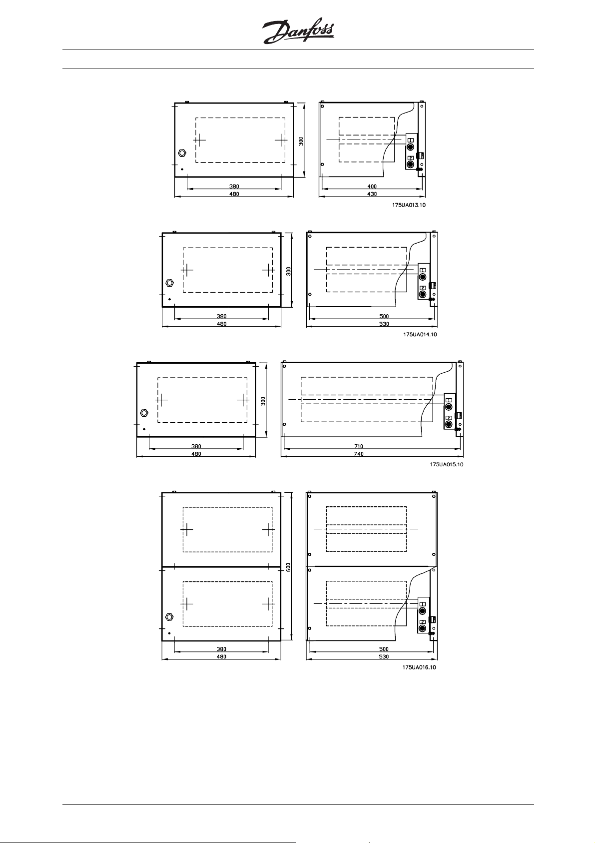
■Drawing no. 1
■Drawing no. 2
VLT®2800/5000/5000 FLUX/FCD 300
■Drawing no. 3
22
MI.90.F1.02 - VLT is a registered Danfoss trademark
Page 23

■Drawing no. 4
■Drawing no. 5
VLT®2800/5000/5000 FLUX/FCD 300
- 19
■Drawing no. 6
Drawings 1
MI.90.F1.02 - VLT is a registered Danfoss trademark
23
Page 24

■Drawing no. 7
■Drawing no. 8
VLT®2800/5000/5000 FLUX/FCD 300
■Drawing no. 9
24
MI.90.F1.02 - VLT is a registered Danfoss trademark
Page 25

■Drawing no. 10
VLT®2800/5000/5000 FLUX/FCD 300
■Drawing no. 11
■Drawing no. 12
- 19
Drawings 1
MI.90.F1.02 - VLT is a registered Danfoss trademark
25
Page 26
■Drawing no. 13
■Drawing no. 14
VLT®2800/5000/5000 FLUX/FCD 300
■Drawing no. 15
■Drawing no. 16
26
MI.90.F1.02 - VLT is a registered Danfoss trademark
Page 27

■Drawing no. 17
■Drawing no. 18
VLT®2800/5000/5000 FLUX/FCD 300
- 19
Drawings 1
MI.90.F1.02 - VLT is a registered Danfoss trademark
27
Page 28
■Drawing no. 19
VLT®2800/5000/5000 FLUX/FCD 300
28
MI.90.F1.02 - VLT is a registered Danfoss trademark
 Loading...