

Page 1
Data sheet
3/2-Way Zone-Drain-Valves
VDHT 2E, VDHT 15E and
VDHT 15EC
hpp.danfoss.com
Page 2

Data sheet | 3/2-Way Zone-Drain-Valves
Table of Contents
Contents
1. Introduction ............................................................................2
2. Overview ...............................................................................3
3. Technical data...........................................................................4
3.1 3/2 way principle........................................................................5
4. Pressure losses at dierent ows.........................................................6
5. Overview coils and accessories ..........................................................7
6. Sub-base manifold ......................................................................8
7. VDHT drawings and spare parts .........................................................9
1. Introduction
The 3/2-way valves are designed for applications
in high-pressure humidication and adiabatic
cooling systems.
Each valve has an IN, OUT and DRAIN port.
When the valve is not in operation the connection between IN and OUT is closed while the
connection between OUT and DRAIN stays
open. This allows to instantanously relief the
pressure at shut down from the application,
typically a nozzle branch, to prevent the nozzle
from dripping. If desired, the nozzle branch can
be entirely drained after shut down to avoid
bacterial growth. Furthermore, each valve has its
individual properties to match exactly the
specic needs in size and functionality.
All of our valves are made of stainless steel (AISI
304) and are suitable for potable and technical
water. They have an extremely long service life for
at least one million operations and are even then
very easy to service.
Inline valves are available with European BSP
thread (G-thread) and American National Pipe
Thread (NPT). For the VDHT 15EC Danfoss oers a
wide range of single and multiple manifolds.
The enclosure rating is IP67, including any
standard coil. A large variety of coils for various
supply voltages is available for all our valves.
AI268451941578en-001101
Page 3

Data Sheet | 3/2-Way Zone-Drain-Valves
2. Overview
VDHT 2E for small ows
VDHT 15E for medium ows
VDHT 15EC Cetop 3
The VDHT 2E is a small valve for minor ow rates
up to 2 litres per minute (0.52 gpm).
It is a direct operated valve with one NO and NC
armature.
The VDHT 2E requires 2 coils activated by a
common signal (ie. 24V a.c.).
It is suitable for systems with many zones with
few nozzles and is a very cost eective solution.
The VDHT 15E is a medium size single inline valve
for ow rates up to 15 litres per minute (4 gpm).
It is comprising a piston type NC valve and a NO
pilot stage in one housing. The NO part has a
relative small orice, so it cannot drain a big
volume very fast.
It covers a very wide ow range already starting
from 1 litre per minute (0.26 gpm).
The VDHT 15E requires 2 coils activated by
acommon signal (ie. 24 V a.c.)
The VDHT 15EC 3/2 is the Cetop 3 variant of the
VDHT 15E, by means that connections are made
through a valve block or multiple vave manifolds.
In multiple valve applicatons up to 5 valves can
be installed on a common manifold side by side,
saving time, space and plumbing eort.
Sub-base valve manifolds
Danfoss oers sub-base manifolds for installin 3,
4 or 5 VDHT 3/2 way valves side by side.
The sub-base manifolds represent a very
cost-eective solution, saving signicantly on
time, space and plumbing eorts, as the number
of connections is minimized.
© Danfoss | DCS (im) | 2021.05 | 3AI268451941578en-001101
Page 4
Data sheet | 3/2-Way Zone-Drain-Valves
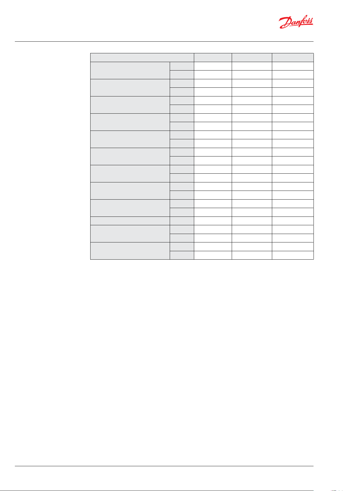
3. Technical data
Description VDHT 2E VD HT 15E VD HT 15EC
Code number
Connection
Max. continuous inlet pressure
Max. peak inlet pressure
Min. operation pressure at inlet
port
Drain opening pressure
Max. ow
Min. ow
Max. drain ow
Opening/closing time ms 250 250 250
Water temperature
Weight without coils
BSP 180L0298 180L0173 180L0240
NPT 180L1017 180L0174
BSP 3 x ¼ ³⁄₈, ³⁄₈, ¼ CETOP 3
NPT 3 x ¼ 3 x ³⁄₈
barg 80 140 140
psig 1150 2000 2000
barg 100 160 160
psig 1450 2300 2300
barg 1 2 2
psig 14.5 29 29
barg 80 80 80
psig 1150 1150 115 0
l/min 2 15 15
gpm 0.52 4 4
l/min 0 1 1
gpm 0 0.26 0.26
l/min 2 5 5
gpm 0.52 1.3 1.3
°C 2-50 2-50 2-50
°F 37-122 37-122 37-122
kg 1.4 1.6 1.7
lbs 3.1 3.5 3.7
AI268451941578en-001101
Page 5

Data Sheet | 3/2-Way Zone-Drain-Valves
3.1 3/2-way principle
Coil de-energized Coil energized
2.3 Soft-Charge principle
Both coils de-energized NC coil energized only
P-port (IN) closed,
B- and t_port conneted
(OUT and DRAIN), application drained
Both coils energized
P-and B-port (IN and OUT) connected,
T-port (DRAIN) closed, full ow to application
P-, T- and B-port
(IN, OUT and DRAIN) connected;
ow partially to application and drain
© Danfoss | DCS (im) | 2021.05 | 5AI268451941578en-001101
Page 6

Data sheet | 3/2-Way Zone-Drain-Valves
4. Pressure losses at
dierent ows
VDHT 2E
psig barg
VDHT 15E and VDHT 15EC
psig
barg
AI268451941578en-001101
Page 7

Data Sheet | 3/2-Way Zone-Drain-Valves
5. Overview coils and
accessories
Description
Code no.
HPP
Voltage Power
Voltage
tolerance
T max
Ambiente
°C (°F)
Connection
Enclosure
Weight
kg (lbs)
Type BB / Without LED / for Hirsch mann plug / excl. plug
Coil 240V-50Hz-10W-IP65 018F7906 240V 50 Hz 11W
Coil 24V-50H z-10W- IP65 018F790 5 24V 50Hz 11W 8 0 (176) DIN 43650-A IP65 0. 2 (0.5)
+/- 10-15%
80 (176) DIN 43650-A IP65 0.2 (0.5)
Coil 24V-DC-18W-IP65 018 F7928 24V DC 16W +/- 10% 50 (122) DIN 43650-A IP65 0.2 (0.5)
Type BE / Without LED / incl. Terminal box
Coil 240 V-6 0Hz-10W -IP67 018F7926 24 0V 60Hz 15W
80 (176) Terminal box IP67 0. 3 (0.7)
Coil 240V-50Hz-10W-IP67 018F7924 240V 50 Hz 11W 8 0 (176) Terminal box IP67 0.3 (0.7)
Coil 220-230V-50Hz-10W-
IP67
Coil 220-230V-50- 60Hz-
10W- IP67
018F7921
018F 7919
Coil 220V-60Hz-10W-IP67 018F7925 220V 60Hz 13 W 80 (17 6) Terminal box IP67 0.3 (0.7)
Coil 200V-50- 60Hz-10W-
IP67
Coil 110V-5 0-6 0Hz-10W-
IP67
018F7929 200V 50/60Hz 10W 8 0 (176 ) Terminal box I P67 0.3 (0.7)
018F7923 110V 50 -6 0H z
220-230 V
50 Hz
220-230 V
50-60Hz
12W 80 (17 6) Terminal box IP67 0.3 (0.7)
17W
14W
50 (122) Terminal box IP67 0.3 (0.7)
+/- 10-15%
15W
13W
50 (122) Terminal box IP67 0.3 (0.7)
Coil 24V-60 Hz-10W- IP67 018F 7922 24V 60Hz 14 W 80 (176) Terminal box IP67 0.3 (0.7)
Coil 24V-50H z-10W- IP67 018F7920 24V 50Hz 12W 80 (176) Terminal box IP67 0.3 (0.7)
Coil 42V-50H z-10W- IP67 018F7927 42V 50Hz 10 W 80 (176) Terminal box IP67 0.3 (0.7)
Coil 24V-DC-18W-IP67 018F7914 24V DC 16W +/- 10% 50 (122) Terminal box IP67 0.3 (0.7)
Coil 12V-DC-18W-IP67 018F7913 12V DC 15 W +/- 10% 50 (122) Terminal box IP67 0.3 (0.7)
Type BE / Without LED / for Hirsch mann plug / prepare for terminal box
Coil 200V-50- 60Hz-10WIP67
018F7918
200V
50/60 Hz
10W
+/- 10-15%
50 (122) Terminal box IP67 0.2 (0.5)
Coil 240V-50Hz-10W-IP67 018F7917 240V 50 Hz 11W 8 0 (176) Terminal box IP67 0.2 (0.5)
Coil 24V-DC-18W-IP67 018F7 912 24V DC 16W +/- 10% 5 0 (122 ) Terminal box IP67 0.3 (0.7)
Type BY / Withou t LED / for Hirschm ann plug / excl. plug / UL Reco gnised
Coil 208-240V-50- 60Hz14W-IP65-UL
Coil 110V-50-60Hz-14WIP65-UL
Coil 24V-50- 60Hz-14WIP65-UL
018F790 8
018F790 9
018F7907
208 -240V
50/60 Hz
110 V
50-60 Hz
24V
50-60 Hz
16W
14W
+/- 10-15%
14W 50 (122 ) DIN43650-A IP65 0.2 (0.5)
14W
12W
50 (122) DIN43650-A IP65 0.2 (0.5)
50 (122) DIN43650-A IP65 0.2 (0.5)
Type BE / excl. LED / Incl. c able
Coil 48V-50-60Hz-10WIP67-4m cable
Type BO / Ex mb II T4 Gb - 2014/34/EU (ATEX) EN60 079-D-2012+A11:2013, EN6 0079-D:2018, EN60079-18:2015 + A1:2017,
Coil Ex mb IIC T4 24V50/60 Hz 10W-IP67
Coil Ex mb IIC T4 110V50/60 Hz 10W-IP67
Coil Ex mb IIC T4 230V50/60 Hz 10W-IP67
Coil Ex mb IIC T4 240V50/60 Hz 10W-IP67
Coil Ex mb IIC T4 Gb
24V DC - IP67-10W-IP67
1)
Due to physical dimensions of the ATEX coil, it is not possible to use these in combination with the
018F7915 48V 50Hz 10W +/- 10 -15% 8 0 (176) 4 mtr. cable IP67 0.3 (0.7)
1)
018Z6 595
018Z6 593
018Z6 592
018Z6 591
018Z6 596
EN60730 -1:2011
24V
2)
50/60 Hz
110 V
2)
50/60 Hz
230V
2)
50/60 Hz
240V
2)
50/60 Hz
2)
24V DC 10W ± 10% 60 (140) 5 m. cable IP67 0 .6 (1.4)
10W ±1 0% 60 (140 ) 5 m. cable IP67 0.6 (1.4))
10W ±1 0% 60 (140 ) 5 m. cable IP67 0.6 (1.4))
10W ±1 0% 60 (140 ) 5 m. cable IP67 0.6 (1.4))
10W ±1 0% 60 (140 ) 5 m. cable IP67 0.6 (1.4))
HPP block valves (BL2 - 5)
2)
Code nos. to be ordered in Danfoss Sensing Solutions (PL04)
© Danfoss | DCS (im) | 2021.05 | 7AI268451941578en-001101
Page 8

Data sheet | 3/2-Way Zone-Drain-Valves
Plug EN175301-803 A
PG9
Plug EN175301-803 A
PG9
Connec ting plug / Typ BY / excl. LED / for Hirschmann connection (DIN 43650-A) UL Recog nised
04 2N125 6
04 2N1278
1)
–
1)
–
Excl
LED
Excl
LED
– 125 (257) BE-BB-BY IP67 0.1 (0.3)
– 90 (194 ) BE-BB-BY IP65 0.1 (0.3)
04 2N125 6
04 2N1278
Connec ting plug / Typ BY / incl. LED / for Hirschmann connec tion (DIN 43650-A) UL Recognised
Plug EN175301-803 A
230V AC/DC LED
Plug EN175301-803 A
24V AC/DC LED + PACK
Terminal box excl. LED
pack unit 100 Pe
Terminal box incl. LED 48220V DC 24-250V-50Hz /
only BE
Permanent magnet 180Z0212 for testing – – – – – 0.3 (0.7)
1)
Code nos. to be ordered in Danfoss Sensing Solutions (PL04)
6. Sub-base manifold 6.1 Manifolds
Typ e Description Code No.
Sub-base manifold for 3 VDHT 15EC 180L0261
Sub-base manifold for 4 VDHT 15EC 180L0262
Sub-base manifold for 5 VDHT 15EC 180L0263
Blind plate to cover spare position 180L0079
1)
042N0265
042N0263
018Z0279 –
018Z0 089
230V AC
1)
24V AC/DC
Connection terminal box / Permanent magnet
48 -220V DC24
1)
-250V 50/60
Incl
LED
Incl
LED
Excl
LED
100 PE
Incl.
Hz
LED
– 60 (140) BE-BB-BY IP65 0.1 (0.3)
– 60 (140) BE-BB-BY IP65 0.1 (0.3)
– 80 (176) BE IP67 0.1 (0.3)
– 80 (176) BE IP67 0.1 (0.3)
AI268451941578en-001101
Page 9

Data Sheet | 3/2-Way Zone-Drain-Valves
7. VDHT drawing spare part
VDHT 2E
Drawings
Spare parts
Spare parts
Armature kit NC 180L5002 / Pos.: 1, 5
Armature kit NO 180L5010 / Pos.: 4, 5
Orice kit NO & NC (1.4 mm) 180Z0097 / Pos.: 6, 7
© Danfoss | DCS (im) | 2021.05 | 9AI268451941578en-001101
Page 10

Data sheet | 3/2-Way Zone-Drain-Valves
VDHT 15 E
Drawings
Spare parts
Spare parts
Armature kit NC 180L5002 / Pos.:1, 5
Armature kit NO 180L5010 / Pos.: 4, 5
Orice kit NC 180Z0098 / Pos.: 6, 7
Orice kit NO 180Z0097 / Pos.: 6, 7
Piston kit Ø18.1 180Z0024 / Pos.: 9, 10, 11
AI268451941578en-001101
Page 11

Data Sheet | 3/2-Way Zone-Drain-Valves
VDHT 15 EC
Drawings
Spare parts
Spare parts
Armature kit NC 180L5002 / Pos.: 1, 5
Armature kit NO 180L5010 / Pos.: 4, 5
Orice kit NC 180Z0098 / Pos.: 6, 7
Orice kit NO 180Z0097 / Pos.: 6, 7
Piston kit 180Z0024 / Pos.: 9, 10
© Danfoss | DCS (im) | 2021.05 | 11AI268451941578en-001101
Page 12

Danfoss A/S
High Pressure Pumps
DK-6430 Nordborg
Denmark
Danfoss ca n accept no respons ibility for pos sible errors in ca talogues, bro chures and other pr inted material. Da nfoss reserves t he right to alter its p roducts with out notice.
This also a pplies to produc ts already on ord er provided that su ch alterations ca n be made without su bsequential cha nges being nece ssary in speci cations alread y agreed.
All trade marks in this mate rial are proper ty of the respec tive companies . Danfoss and the Dan foss logotyp e are trademark s of Danfoss A/S. Al l rights reserv ed.
12 | © Danfoss | DCS (im) | 2021.05
AI268451941578en-001101
 Loading...