

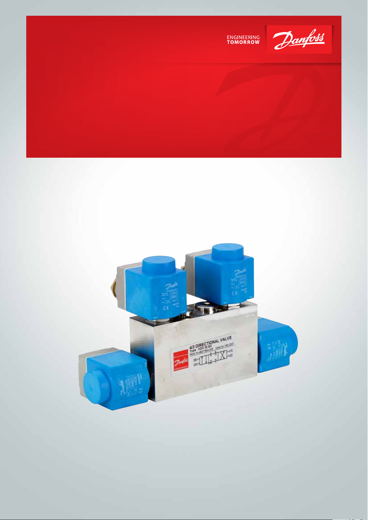
Data sheet
Directional control valve
VDH 30EC 4/3
For Cetop 3 flange mounting (ISO 4401)
and inline mounting
hpp.danfoss.com
Data Sheet | Directional Control Valve VDH 30EC 4/3
Introduction The VDH 30 EC is designed for controlling the
direction of water ow.
The valves are designed for tap water, i.e. without
additives (EU-Directive 98/83/EC).
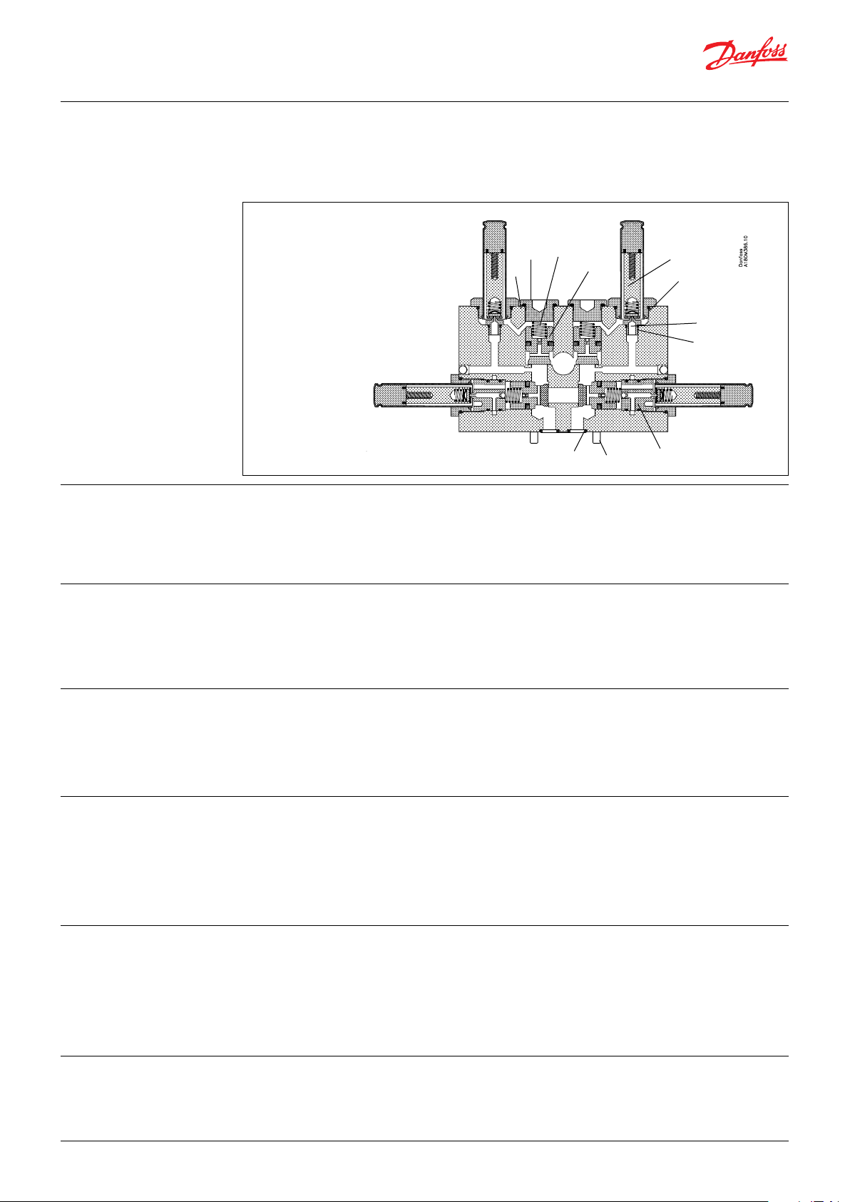
1. Armature
2. O-ring
3. Orice
4. O-ring
5. O-ring
6. Plug
7. Spring
8. Poppet
9. Orice insert
10. Screw
11. O-ring
Function
The directional valves are pilot operated On/O
seat valves electrically activated by 4 coils.
The valves are designed according to the seat
valve principle where each individual seat valve is
controlled by its own pilot stage.
7
6
5
8
1
2
3
4
11
10
9
This valve type contains 4 seat valves altogether:
two inlet valves and two outlet valves. As each
seat valve is individually controlled by its own
pilot, this design oers many
dierent valve congurations to the end user.
Features
• Installable on all Cetop 3 blocks and inline
blocks
• Corrosion resistant surfaces
• Easy-to-clean surfaces
Versions The valve housing comes in standard version
in stainless steel AISI 304 (W. No. 1.4301) or
ISI 316 (W. No. 1.4401)
Temperature
Storage temperature:
• -40°C to +70°C [ -40 to 158 °F] – provided
that the valve is drained of uid and stored
”plugged”
Operation on (clean) water:
• Fluid temperature and ambient temperature:
+3°C to +50°C [37 to 122 °F]
Antifreeze Protection
If a system requires antifreeze protection, Danfoss
recommends Dowcall N or Chillsafe mono propylene glycol from the Dow Chemical Company
and Arco Chemical Company, respectively. Both
antifreezes are biologically degradable and must
be used together with demineralized water.
• The seat valve design ensures minimum
leakage
• High degree of enclosure, IP67
• Many valve congurations available
The valve is available as a Normally Close
valve (NC) or in a combination of Normally
Open (NO) and Normally Closed (NC
Operation on water containing antifreeze:
• Fluid temperature and ambient temperature:
-30°C 1) to +50°C [-22 to 122 °F]
1)
please see paragraph on antifreeze protection
Mixing ratio must be:
• min. 30% antifreeze and 70% demine ralized water providing frost protection to
–13°C [9 °F] and preventing biolm in the
system.
• max. 50% antifreeze and 50% demine ralized water due to increased viscosity,
providing frost protection to –30°C [-22 °].
Filtration
2 | © Danfoss | DCS (im) | 2019.10
The water supply must be ltered through a
10 µm abs., β
-value > 5000 lter.
10
For further lter details, please contact the
Danfoss Sales Organization.
AI319740679646en-000801| 521B0605 |
Data Sheet | Directional Control Valve VDH 30EC 4/3
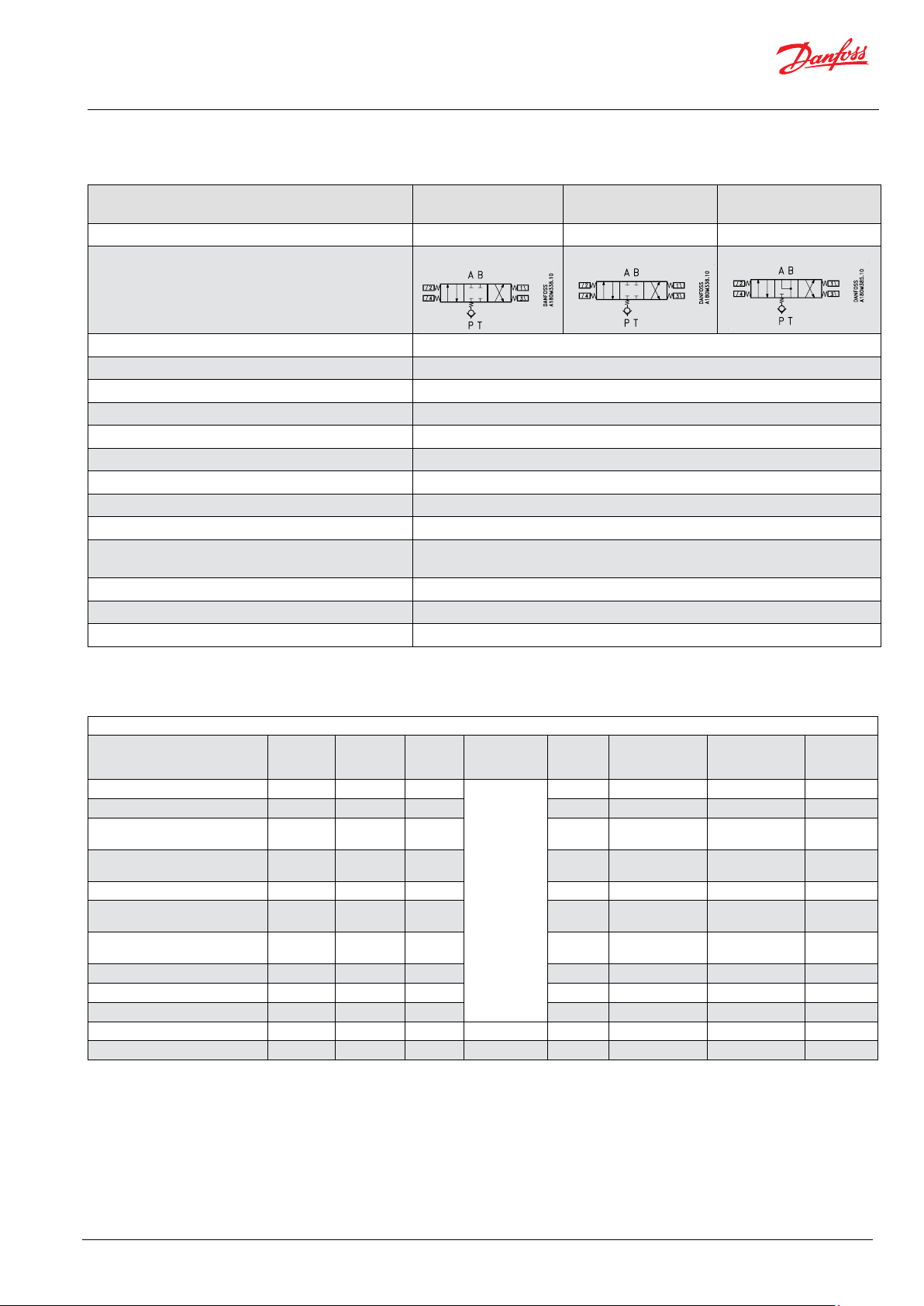
Technical data and
Code numbers
Valve body
VDH 30EC - NC
Stainless steel, AISI 304
VDH 30EC - NC
Stainless steel, AISI 316
VDH 30 EC 2xNC + 2x NO
Stainless steel, AISI 3040
Code number 180L0046 180L0047 180L0050
Function symbol
Max. pressure port P, A and B
Return pressure, port T (T ≤ A, B pressure
1)
1)
140 barg [2030 psig]
140 barg [2030 psig]
Min. inlet pressure 5 barg [72.5 psig]
Max. ow 30 l/min [8 gpm]
Min. ow 1 l/min [0.2 gpm]
Pressure loss See curve page 4
Leakage, port P → A, B, T 0 ml/min [ 0 gpm]
Leakage, port A, B → T 0 ml/min [ 0 gpm]
Leakage, port A, B → P (inlet pressure port P = 0 barg) max. 5 ml/min [ max. 0.0013 gpm]
Leakage, port A, B → P
(inlet pressure port P = pressure port A,B)
Opening time when changing direction
Closing time when changing direction
2)
2)
0 ml/min [0 gpm]
110 ms
130 ms
Weight 3.8 kg [ 8 lbs]
The valves are supplied with screw and O-rings,
but without coils.
Coils type BE / Without LED / incl. Terminal box
Description Code no. Voltage Power
Coil 240V-60Hz-IP67 018F7926 240V 60Hz 15W
Voltage
tolerance
T max
Ambient
°C [°F]
Connection Enclosure
Weight
kg [lbs]
80 [176] Terminal box IP67 0.3 [0.7]
Coil 240V-50Hz-IP67 018F7924 240V 50Hz 11W 80 [176] Terminal box IP67 0.3 [0.7]
Coil 220-230V-50Hz-IP67 018F7921
Coil 220-230V-50-60Hz-IP67 018F7919
Coil 220V-60Hz-IP67 018F7925 220V 60Hz 13W 80 [176] Terminal box IP67 0.3 [0.7]
Coil 200V-50-60Hz-IP67 018F7929
Coil 110V-50-60Hz-IP67 018F7923
220-230 V
50 Hz
220-230 V
50-60Hz
200V
50/60Hz
110V 50-
60Hz
12W 80 [176] Terminal box IP67 0.3 (0.7)
17W
14W
50 [122] Terminal box IP67 0.3 [0.7]
± 10-15%
10W 80 [176] Terminal box IP67 0.3 [0.7]
15W
13W
50 [122] Terminal box IP67 0.3 [0.7]
Coil 24V-60Hz-IP67 018F7922 24V 60Hz 14W 80 [176] Terminal box IP67 0.3 [0.7]
Coil 24V-50Hz-IP67 018F7920 24V 50Hz 12W 80 [176] Terminal box IP67 0.3 [0.7]
Coil 42V-50Hz-IP67 018F7927 42V 50Hz 10W 80 [176] Terminal box IP67 0.3 [0.7]
Coil 24V-DC- IP67 018F7914 24V DC 16W ± 10% 50 [122] Terminal box IP67 0.3 [0.7]
Coil 12V-DC- IP67 018F7913 12V DC 15W ± 10% 50 [122] Terminal box IP67 0.3 [0.7]
© Danfoss | DCS (im) | 2019.10 AI319740679646en-000801| 521B0605| 3

Data Sheet | Directional Control Valve VDH 30EC 4/3
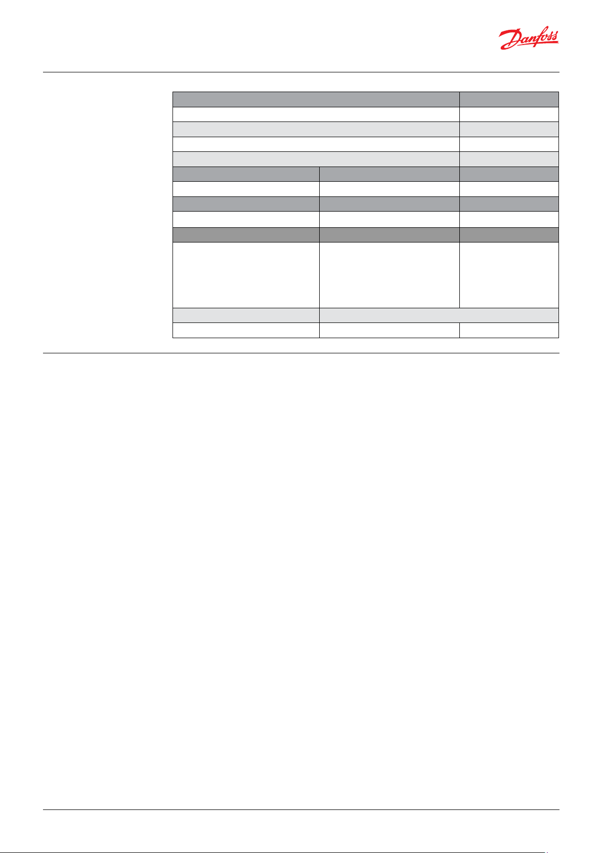
Code numbers
(continued)
Pressure losses at
dierent ows
Cetop 3 blocks
Description
Inline block for 1 valve (P&T direct for VPH 15E) 0.8 [1.7] 180L0060
Block for 1 valve 2.4 [5.3] 180L0081
Block for 2 valves 4.4 [9.7] 180L0082
Block for 3 valves 7.3 [16.1] 180L0083
Block for 4 valves 9.6 [21.2] 180L0084
Cover plate incl. screws and O-ring
(for covering-up non-used valve outlets on block)
Weight
kg [lbs]
0.1 [0.2] 180L0079
Code number
4 | © Danfoss | DCS (im) | 2019.10
AI319740679646en-000801| 521B0605 |

Data Sheet | Directional Control Valve VDH 30EC 4/3
Available valve
congurations
The table below shows the possible valve
congurations, depending on which coils are
activated.
For VDH 30EC 4/3 NC
Diagram showing ow routes through the valve,
port lettering and coil numbers.
For VDH 30EC 4/3 NC + NO
For VDH 30EC 4/3 NC
© Danfoss | DCS (im) | 2019.10 AI319740679646en-000801| 521B0605| 5
For VDH 30EC 4/3 NC + NO

Data Sheet | Directional Control Valve VDH 30EC 4/3
Dimensions (mm)
VDH 30EC 4/3
6 | © Danfoss | DCS (im) | 2019.10
AI319740679646en-000801| 521B0605 |

Data Sheet | Directional Control Valve VDH 30EC 4/3
Dimensions (mm)
Inline block for 1 valve
180L0060
Dimensions (mm)
Cetop blocks
P and T ports:
G ½, 15,5 mm deep
A and B ports:
G 3/8, 13 mm deep
© Danfoss | DCS (im) | 2019.10 AI319740679646en-000801| 521B0605| 7
Data Sheet | Directional Control Valve VDH 30EC 4/3
Spare parts
Code numbers
Mounting of v alve on Cetop
block
Spare parts Code number
Poppet kit (pos. 8) 180L5005
Armature kit, NC (pos. 1) 180L5002
Armature kit, NO (pos. 1) 180L5010
Orice kit 180Z0099 + 180Z0098
O-ring for mounting on block Dimensions Code number
NBR, 1 pc (pos. 11) 9.25 x 1.78 633B1243
Assembly screw Tightening torque Code number
M5 x 40 ISO 4762 A4, 1 pc (pos. 10) 7 Nm 681X0162
Tools Application Code number
Mounting/dismounting of orice
Orice inser in valve housing:
Special tool for orice insert
Spool tool incl. in 180L5005 Mounting of spool
Permanent magnent For mounting activation of valve 180Z0212
The valve is designed to be mounted on a block
with CETOP 3-port connection. Four stainless
steel screws and four O-rings are supplied with
the valve for mounting. Remember to smear/
12 Nm ± 2 NM
Armature to be screwed into the
valve housing:
60 Nm ± 2 Nm
spray the threads on the screws with Molykote®
D pasta from Dow Corning, or Klüber UH1 84-201
from Klüber lubrication, before mounting the
valve.
180Z0034
8 | © Danfoss | DCS (im) | 2019.10
AI319740679646en-000801| 521B0605 |

Data Sheet | Directional Control Valve VDH 30EC 4/3
Mounting of coil
Coil on valves with short armature tubes (NC and
NO valves)
1. Place the o-ring on the armature tube.
2. The coil is clicked on by means of a light pressure by hand – without using tools.
Dismounting of coil
© Danfoss | DCS (im) | 2019.10 AI319740679646en-000801| 521B0605| 9
Danfoss A/S
High Pressure Pumps
Nordborgvej 81
DK-6430 Nordborg
Denmark
© Danfoss | DCS (im) | 2019.10
AI319740679646en-000801| 521B0605 | 10
 Loading...