

Page 1
Data sheet.
2/2 way Directional Control Valves, type VDH
2/2-way Directional Control Valves
For inline mounting and Cetop 3 ange mounting (ISO 4401)
VDH
For inline mounting and Cetop 3 ange
mounting (ISO 4401)
Inline versions:
Cetop 3 block version:
Application
Function
Advantages
Variants
Filtration
• VDH 30 E 2/2,
• VDH 60 E 2/2,
• VDH 120 E 2/2
Directional valves are used to control water ow
direction.
The directional valves are pilot operated On/O
2/2-way seat valves electrically activated by 1
coil.
• Corrosion resistant surfaces
• Easy to clean surfaces
• The seat valve design ensures zero leakage
The valve housing comes in standard version in
stainless steel AISI 304 (W. nr. 1.4301).
The valve is available as a normally closed valve
(NC) or as a normally open valve (NO).
The water supplied to the valve must be ltered:
10 µm absolute, β
recommended.
-value > 5000 lter is
10
• VDH 30 EC 2/2
The valves are designed for tap water, i.e. without
additives (EU-Directive 98/83/EC).
• High degree of protection, IP 67
• Cetop valve installable on all cetop 3 blocks
On request the valve housing is obtainable in
stainless steel AISI 316 L (W. nr. 1.4401), please
contact the Danfoss Sales Organization for Water
Hydraulics.
For further information on lters, please contact
the Danfoss sales department for water hydraulics.
hpp.danfoss.com.
Page 2
Data sheet | Directional Control valves VDH
1. Introduction
2. VDH valve
selection overview
The VDH directional control valves are designed
for applications with tap water, i.e. without
additives (EU-Directive 98/83/EC).
The directional valves are used to control water
ow direction.
Function
The directional valves are pilot operated On/O
2/2-way seat valves electrically activated by 1 coil.
Features
• Corrosion resistant surfaces
• Easy to clean surfaces
• The seat valve design ensures zero leakage
• High degree of protection, IP 67
• Cetop valve installable on all cetop 3 blocks
•
Filtration
The water supplied to the valve must be ltered:
10 µm absolute, ß
-value > 5000 lter is
10
recommended.
For further information on lters, please contact
the Danfoss sales department for High Pressure
Pumps.
E Straight ow direction
EC Cetop 3 manifolde
Versions
Inline versions:
• VDH 30 E 2/2
• VDH 60E 2/2
• VDH 120 E 2/2
Cetop 3 block version:
• VDH 30 EC 2/2
The valve housing comes in standard version in
stainless steel AISI 304 (W.no. 1.4301).
The valve is available as a normally closed valve
(NC) or as a normally open valve (NO).
On request the valve housing is obtainable in
stainless stel AISI 316L (W.no. 1.4401), please
contact the Danfoss Sales Organization for High
Pressure Pumps.
Temperature
Operation on (clean) water:
Fluid temperature and ambient temperature:
3 °C – 50 °C.
Operation on water containing antifreexe:
Fluid temperature and ambient temperature:
-30 °C – 50 °C
1).
Storage temperature:
-40 °C – 70 °C
provided that the valve is drained of uid and
stored "plugged".
Antifreeze protection
1)
If a system requires antifreeze protection, Danfoss
recommends Dowcall N or Chillsafe mono propylene glycol from the Dow Chemical Company and
Arco Chemical Company, respectively.
Both antifreezes are biologically degradable and
must be used together with demineralized water.
Mixing ratio must be:
• Min. 30% antifreeze and 70% demineralize
water providing frost protection to -13 °C
and preventing biolm in the system.
• Max. 50% antifreeze and 50% demineralize
water due to increased viscosity, providin
frost protection to -30 °C.
2
521B0613 | DKCFN.PD.042.G4.02 | 02.2020
Page 3
Data sheet | Directional Control valves VDH
3. Code numbers and
technical data
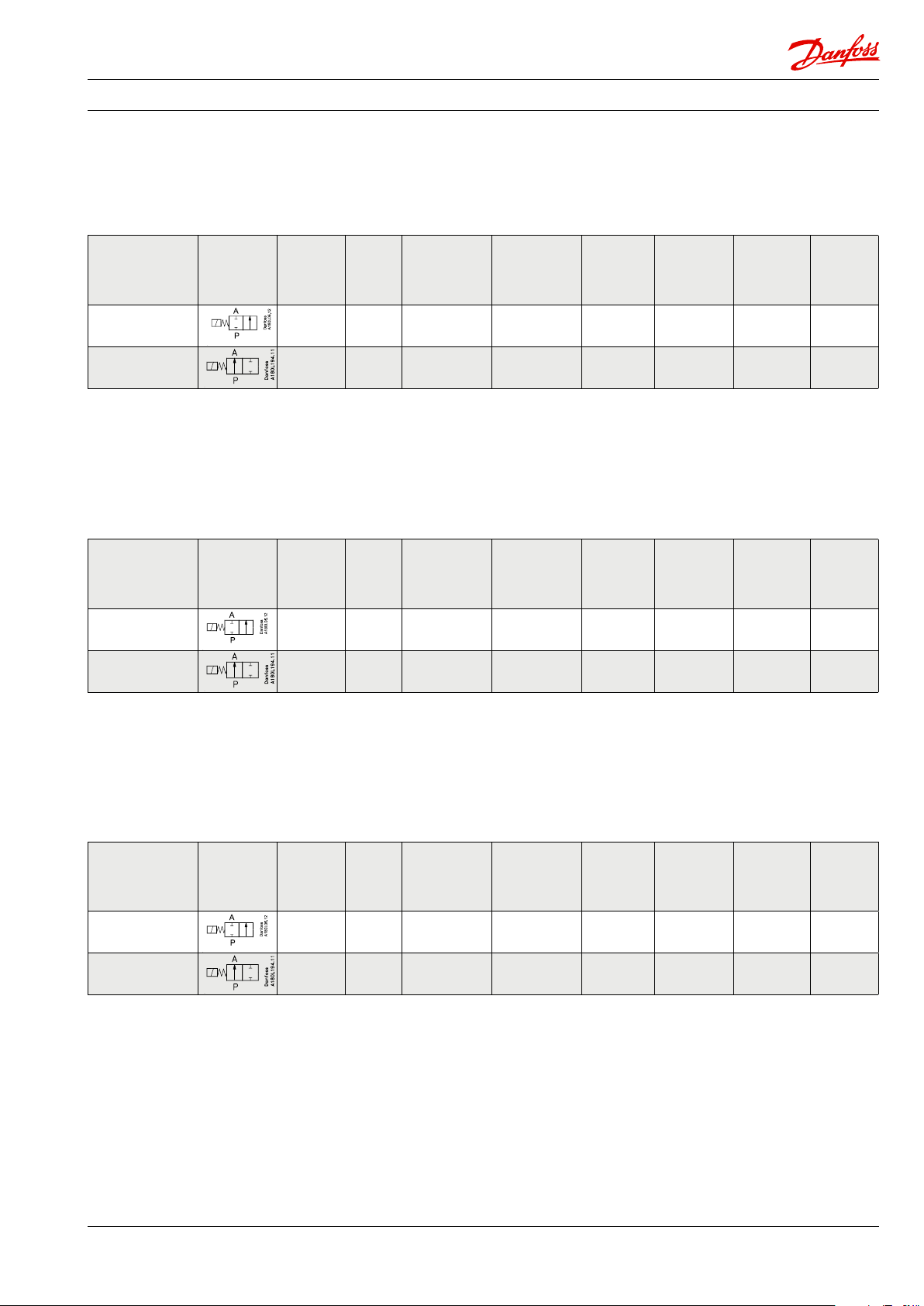
2/2-way directional control valves, type VDH 30 E
Pressure loss at max. ow: 6 barg (87 psig)
Max. opening/closing time: 150 ms/350 ms
Leakage at pressure higher tha 10 barg (145 psig): 0 ml/min (0 GPM) drip proof
Degree of protection: IP 67
Type
Function
symbol
VDH 30 E 2/2 NC
VDH 30 E 2/2 NO
1)
The pressure in port P must always be higher than the pressur in port A (Pp>Pa)
Code
number
Connection
180L0002 G 3/8 " 140 (2.030) 200 (2,900) 3.5 (50.7) 30 (7.9) 1 (0.3) 1.6 (3.8)
180L0003 G 3/8 " 140 (2.030) 170 (2,465) 3.5 (50.7) 30 (7.9) 1 (0.3) 1.6 (3.8)
Max. inlet
pressure cont.
barg (psig)
Max inlet
pressure peak
barg (psig)
2/2-way directional control valves, type VDH 30 EC
Pressure loss at max. ow: 7 barg (101.5 psig)
Max. opening/closing time: 150 ms/350 ms
Leakage at pressure higher tha 10 barg (145 psig): 0 ml/min (0 GPM) drip proof
Degree of protection: IP 67
Type
Function
symbol
Code
number
Connection
Max. inlet
pressure cont.
barg (psig)
Max inlet
pressure peak
barg (psig)
Operation
pressure
barg (psig)
Operation
pressure
barg (psig)
1)
Max. ow
l/min (GPM)
1)
Max. ow
l/min (GPM)
Min. ow
l/min
(GPM)
Min. ow
l/min
(GPM)
Weight
incl. coil
kg (lb)
Weight
incl. coil
kg (lb)
VDH 30 EC2/2
NC
VDH 30 EC 2/2
NO
1)
The pressure in port P must always be higher than the pressur in port A (Pp>Pa)
180L0048 Cetop 3 140 (2.030) 200 (2,900) 3.5 (50.7) 30 (7.9) 1 (0.3) 1.2 (2.1)
180L0049 Cetop 3 140 (2.030) 170 (2,465) 3.5 (50.7) 30 (7.9) 1 (0.3) 1.2 (2.1)
VDH 30EC 2/2-way valves are supplied with screws and O-rings.
2/2-way directional control valves, type VDH 60 E
Pressure loss at max. ow: 8 barg (116 psig)
Max. opening/closing time: 150 ms/350 ms
Leakage at pressure higher tha 10 barg (145 psig): 0 ml/min (0 GPM) drip proof
Degree of protection: IP 67
Type
Function
symbol
VDH 60 E 2/2 NC
VDH 60 E 2/2 NO
1)
The pressure in port P must always be higher than the pressur in port A (Pp>Pa)
Code
number
Connection
180L0011 G ½" 140 (2.030) 200 (2,900) 3.5 (50.7) 60 (15.8) 1 (0.3) 1.6 (3.8)
180L0015 G ½" 140 (2.030) 170 (2,465) 3.5 (50.7) 60 (15.8) 1 (0.3) 1.6 (3.8)
Max. inlet
pressure cont.
barg (psig)
Max inlet
pressure peak
barg (psig)
Operation
pressure
barg (psig)
1)
Max. ow
l/min (GPM)
Min. ow
l/min
(GPM)
Weight
incl. coil
kg (lb)
521B0613 | DKCFN.PD.042.G4.02 | 02.2020
3
Page 4

Data sheet | Directional Control valves VDH
2/2-way directional control valves, type VDH 120 E
Pressure loss at max. ow: 6 barg (87 psig)
Max. opening/closing time: 150 ms/400 ms
Leakage at pressure higher tha 10 barg (145 psig): 0 ml/min (0 GPM) drip proof
Degree of protection: IP 67
Type
Function
symbol
VDH 120 E 2/2 NC
VDH 120 E 2/2 NO
1)
The pressure in port P must always be higher than the pressur in port A (Pp>Pa)
Code
number
Connection
180L0001 G ½" 140 (2.030) 200 (2,900) 1 (14.5) 120 (31.6) 5 (1.5) 1.8 (3.9)
180L0005 G ½" 140 (2.030) 170 (2,465) 1 (14.5) 120 (31.6) 5 (1.5) 1.8 (3.9)
Max. inlet
pressure cont.
barg (psig)
Max inlet
pressure peak
barg (psig)
All valves are supplied without coils which must be
ordered separately.
3. Code numbers for
CETOP block
Cetop 3 block Steel type Weight kg (lb) Code number
Block for Cetop 2 valves AISI 304 1.8 (3.9) 180L0062
Block for Cetop 3 valves AISI 304 2.6 (5.7) 180L0063
Block for Cetop 4 valves AISI 304 3.4 (7.5) 180L0064
4. Code numbers for
Coils
Coil voltage Code number
Coil 24V-50Hz-12W-IP 67 018F7920
Coil 220-230V-50Hz-12W-IP 67 018F7921
Coil 240V-50Hz-11W-IP 67 018F7924
Coil 24V-60Hz-14W-IP 67 018F7922
Coil 220V-60Hz-13W-IP 67 018F7925
Coil 240V-60Hz-15W-IP 67 018F7926
Coil 110V-50-60 Hz-15/13W-IP 67 018F7923
Coil 12V -DC-16W-IP 67 018F7913
Coil 24V-DC-16W-IP67 018F7914
Operation
pressure
barg (psig)
1)
Max. ow
l/min (GPM)
Min. ow
l/min
(GPM)
Weight
incl. coil
kg (lb)
ATEX - please consult the Danfoss salesorganization for High Pressure Pumps.
4
521B0613 | DKCFN.PD.042.G4.02 | 02.2020
Page 5

Data sheet | Directional Control valves VDH
5. Pressure losses at
dierent ows
VDH 30 E 2/2 and VDH 30 EC 2/2
VDH 60 E 2/2 and VDH 120 E 2/2
521B0613 | DKCFN.PD.042.G4.02 | 02.2020
5
Page 6

Data sheet | Directional Control valves VDH
6. Cross-section of
valves
VDH 30 E 2/2 and VDH 60 E 2/2
1. Armature
2. O-ring
3. Orice
4. Spring
5. Poppet
VDH 120 E 2/2
1. Armature
2. O-ring
3. O-ring
4. Orice
5. Spring
6. Poppet
6
521B0613 | DKCFN.PD.042.G4.02 | 02.2020
Page 7

Data sheet | Directional Control valves VDH
VDH 30 E C 2/2 (Cetop)
1. Armature
2. O-ring
3. O-ring
4. Orice
5. O-ring
6. Plug
7. Spring
8. Poppet
9. O-ring
10. Screw
7. Dimensions
VDH 30 E 2/2 and VDH 60 E 2/2
All dimensions in mm
521B0613 | DKCFN.PD.042.G4.02 | 02.2020
7
Page 8

Data sheet | Directional Control valves VDH
VDH 120 E 2/2
All dimensions in mm
VDH 30 EC 2/2 (Cetop)
All dimensions in mm
8
521B0613 | DKCFN.PD.042.G4.02 | 02.2020
Page 9

Data sheet | Directional Control valves VDH
Cetop blocks
All dimensions in mm
A B C D E F
Block for 2 valves 30 80 - - 110 86
Block for 3 valves 30 80 130 - 160 136
Block for 4 valves 30 80 130 180 210 186
8. Mounting of in-line
valves
9. Mounting of valve on
Cetop block
10. Mounting of coil on
valve
Inline valves are mounted in line in ow direction
(follow the arrow on the valve) and xed either
The valve is designed to be mounted on a block
with CETOP 3-port connection. Four stainless
steel screws and four O-rings are supplied with
the valve for mounting. Remember to smear/
directly in the pipe connections or with bolts in
the xation holes on the valve.
spray the threads on the screws with Molykote® D
pasta from Dow Corning, or Klüber UH1 84-201
from Klüber lubrication, before mounting the
valve.
Coil on valves with short armature tubes (NC and
NO valves)
1. Place the o-ring on the armature tube.
2. The coil is clicked on by means of a light
pressure by hand – without using tools.
521B0613 | DKCFN.PD.042.G4.02 | 02.2020
9
Page 10

11. Dismounting of coil
12. Accessories
Code numbers
Spare parts Code mumber
Poppet kit for VDH 30E 2/2, VDH 30 EC2/2 and 2/2 VDH 60E 2/2 180L5005
Poppet kit for VDH120E 2/2 (pos. 6) 180L5001
Armature kit, NC (pos. 1) 180L5002
Armature kit, NO (pos. 1) 180L5010
Orice kit VDH 30 E 2/2 180Z0099
Orice kit VDH 60 E 2/2 180Z0099
Orice kit VDH 120 E 2/2 180Z0098
Tools Application Code number
Mounting/dismounting of orice
Special tool for orice insert
Spool tool included in 180L5005 Mounting of spool
Permanent magnet For manual activation of valve 180Z0212
Orice insert in valve housing:
12 Nm ± 2 Nm
Armature to be screwed into the valve
housing: 60 Nm ± 2 Nm
180Z0034
Danfoss A/S
High Pressure Pumps
Nordborgvej 81
DK-6430 Nordborg
Denmark
© Danfoss | DCS (im) | 2020.02
521B0613 | DKCFN.PD.042.G4.02 | 10
 Loading...