

Page 1

vacon
ac drives
devicenet option board opte7
user manual
®
Page 2

Page 3

vacon • 0
TABLE OF CONTENTS
Document: DPD01171B
Release date : 30.01.2015
1. Safety...............................................................................................................2
1.1 Danger................................................................................................................................2
1.2 Warnings ............................................................................................................................3
1.3 Earthing and earth fault protection ...................................................................................4
2. DeviceNet option board OPTE7 - General.........................................................5
2.1 Overview .............................................................................................................................5
2.1.1 DeviceNet physical layer and media..................................................................................5
2.2 DeviceNet protocol description .........................................................................................7
2.2.1 EDS (Electronic Data Sheet) file ........................................................................................8
3. DeviceNet option board OPTE7 - technical data ...............................................9
3.1 General...............................................................................................................................9
3.2 CAN cable...........................................................................................................................9
3.2.1 Recommended cable .......................................................................................................10
4. OPTE7 layout and connections .......................................................................11
4.1 Layout and connections ...................................................................................................11
4.2 LED Indications ................................................................................................................12
4.3 Jumpers ...........................................................................................................................14
5. Installation.....................................................................................................16
5.1 Installation in Vacon® 100...............................................................................................16
5.2 Prepare for use through fieldbus ....................................................................................18
5.3 Installation in Vacon® 20.................................................................................................21
5.3.1 Frames MI1, MI2, MI3 ......................................................................................................21
5.3.2 Frames MI4, MI5 ..............................................................................................................24
5.4 Installation in Vacon® 20 X and 20 CP ............................................................................28
5.5 Installation in Vacon® 100 X (Frames MM4-MM6) .........................................................31
6. Commissioning ..............................................................................................35
6.1 Parameter view ................................................................................................................35
6.2 Monitor view .....................................................................................................................35
6.3 Software info view ............................................................................................................36
6.4 Fieldbus parametrisation ................................................................................................36
6.4.1 Fieldbus control and basic reference selection ..............................................................36
6.4.2 Torque control parametrisation ......................................................................................37
6.4.3 Process data mapping and default settings....................................................................37
7. DeciveNet interface........................................................................................39
7.1 I/O messaging ..................................................................................................................39
7.1.1 Connection behaviour ......................................................................................................39
7.1.2 Input and Output Assemblies...........................................................................................40
7.1.3 Control Supervisor Behaviour .........................................................................................49
7.2 Explicit messaging ...........................................................................................................51
7.2.1 Connection behaviour ......................................................................................................51
8. Fault handling................................................................................................52
8.1 General and additional error codes.................................................................................53
9. Appendix A: Object dictionary ........................................................................54
9.1 Implemented CIP objects.................................................................................................54
9.1.1 List of Object Classes.......................................................................................................54
9.1.2 List of Services.................................................................................................................55
9.1.3 Class Code 0x01 - Identity Object ....................................................................................56
9.1.4 Class Code 0x02 - Message Router Object......................................................................58
9.1.5 Class Code 0x03 - DeviceNet Object................................................................................58
24-hour support +358 (0)201 212 575 • Email: [email protected]
Page 4

vacon • 1
9.1.6 Class Code 0x04 - Assembly Object ................................................................................61
9.1.7 Class Code 0x05 - DeviceNet Connection Object ............................................................62
9.1.8 Class Code 0x28 - Motor Data Object ..............................................................................65
9.1.9 Class Code 0x29 - Control Supervisor Object .................................................................67
9.1.10 Class Code 0x2A - AC/DC Drive Object............................................................................70
9.1.11 Class Code 0xA0 - Vendor Parameter Object..................................................................72
10. Appendix B: Communication attribute details................................................74
10.1 DeviceNet’s use of the CAN Identifier Field ....................................................................74
10.2 Connection object paths...................................................................................................74
11. Appendix C: Fault and warning codes ............................................................76
Tel. +358 (0) 201 2121 • Fax +358 (0)201 212 205
Page 5

Safety vacon • 2
9000.emf
13006.emf
9001.emf
9000.emf
9000.emf
9000.emf
9000.emf
9000.emf
9000.emf
1. SAFETY
This manual contains clearly marked cautions and warnings that are intended for your personal
safety and to avoid any unintentional damage to the product or connected appliances.
Please read the information included in cautions and warnings carefully.
The cautions and warnings are marked as follows:
Table 1. Warning signs
= DANGER! Dangerous voltage
= WARNING or CAUTION
= Caution! Hot surface
1.1 Danger
The components of the power unit are live when the drive is connected to mains
potential. Coming into contact with this voltage is extremely dangerous and may
cause death or severe injury.
The motor terminals U, V, W and the brake resistor terminals are live when the
AC drive is connected to mains, even if the motor is not running.
After disconnecting the AC drive from the mains, wait until the indicators on the
keypad go out (if no keypad is attached, see the indicators on the cover). Wait 5
more minutes before doing any work on the connections of the drive. Do not open
the cover before this time has expired. After expiration of this time, use a
measuring equipment to absolutely ensure that no
ensure absence of voltage before starting any electrical work!
The control I/O-terminals are isolated from the mains potential. However, the
relay outputs and other I/O-terminals may have a dangerous control voltage
present even when the AC drive is disconnected from mains.
voltage is present.
Always
Before connecting the AC drive to mains make sure that the front and cable
covers of the drive are closed.
During a ramp stop (see the Application Manual), the motor is still generating
voltage to the drive. Therefore, do not touch the components of the AC drive
before the motor has completely stopped. Wait until the indicators on the keypad
go out (if no keypad is attached, see the indicators on the cover). Wait additional 5
minutes before starting any work on the drive.
24-hour support +358 (0)201 212 575 • Email: [email protected]
1
Page 6
vacon • 3 Safety
13006.emf
13006.emf
13006.emf
13006.emf
13006.emf
13006.emf
13006.emf
13006.emf
13006.emf
13006.emf
1.2 Warnings
The AC drive is meant for fixed installations only.
Do not perform any measurements when the AC drive is connected to the mains.
The earth leakage current of the AC drives exceeds 3.5mA AC. According to
standard EN61800-5-1, a reinforced protective ground connection must be
ensured. See Chapter 1.3.
If the AC drive is used as a part of a machine, the machine manufacturer is
responsible for providing the machine with a supply disconnecting device (EN
60204-1).
Only spare parts delivered by Vacon can be used.
At power-up, power brake or fault reset the motor will start immediately if the
start signal is active, unless the pulse control for
Furthermore, the I/O functionalities (including start inputs) may change if
parameters, applications or software are changed. Disconnect, therefore, the
motor if an unexpected start can cause danger.
Start/Stop logic has been selected
.
The motor starts automatically after automatic fault reset if the auto restart
function is activated. See the Application Manual for more detailed information.
Prior to measurements on the motor or the motor cable, disconnect the motor
cable from the AC drive.
Do not touch the components on the circuit boards. Static voltage discharge may
damage the components.
Check that the EMC level of the AC drive corresponds to the requirements of your
supply network.
Tel. +358 (0) 201 2121 • Fax +358 (0)201 212 205
1
Page 7
Safety vacon • 4
13006.emf 13006.emf
1.3 Earthing and earth fault protection
CAUTION!
The AC drive must always be earthed with an earthing conductor connected to the earthing terminal
marked with .
The earth leakage current of the drive exceeds 3.5mA AC. According to EN61800-5-1, one or more
of the following conditions for the associated protective circuit must be satisfied:
a) The protective conductor must have a cross-sectional area of at least 10 mm
Al, through its total run.
b) Where the protective conductor has a cross-sectional area of less than 10 mm
2
Al, a second protective conductor of at least the same cross-sectional area must be
mm
provided up to a point where the protective conductor has a cross-sectional area not less
than 10 mm
2
Cu or 16 mm2 Al.
c) Automatic disconnection of the supply in case of loss of continuity of the protective
conductor.
2
Cu or 1 6 mm2
2
Cu or 16
The cross-sectional area of every protective earthing conductor which does not form part of the
supply cable or cable enclosure must, in any case, be not less than:
-2.5mm
-4mm
2
if mechanical protection is provided or
2
if mechanical protection is not provided.
The earth fault protection inside the AC drive protects only the drive itself against earth faults in the
motor or the motor cable. It is not intended for personal safety.
Due to the high capacitive currents present in the AC drive, fault current protective switches may
not function properly.
Do not perform any voltage withstand tests on any part of the AC drive. There is
a certain procedure according to which the tests must be performed. Ignoring
this procedure can cause damage to the product.
NOTE! You can download the English and French product manuals with applicable safety,
warning and caution information from www.vacon.com/downloads
.
REMARQUE Vous pouvez télécharger les versions anglaise et française des manuels produit
contenant l’ensemble des informations de sécurité, avertissements et mises en garde
applicables sur le site www.vacon.com/downloads
.
24-hour support +358 (0)201 212 575 • Email: [email protected]
1
Page 8

vacon • 5 DeviceNet option board OPTE7 - General
DeviceNet
master
9391.emf
Slave Slave Slave Slave Slave
2. DEVICENET OPTION BOARD OPTE7 - GENERAL
2.1 Overview
OPTE7 is a DeviceNet option board for Vacon AC drives. It allows the AC drive to be controlled using
the DeviceNet protocol. The option board implements the AC Drive device profile as defined by CIP.
The OPTE7 option board connects a drive into the DeviceNet network. There can be 64 nodes in one
network. The baud rate is up to 500 kbit/s. The DeviceNet master can control and monitor the drives.
Figure 1. Typical DeviceNet network structure
2.1.1 DeviceNet physical layer and media
The basic trunkline-dropline topology provides separate twisted pair busses for both signal and
power distribution. Thick or thin cable can be used for either trunklines or droplines. End-to-end
network distance varies with data rate and cable size.
Devices can be powered directly from the bus and communicate with each other using the same
cable. Nodes can be removed from or inserted to the network without powering down the network.
Power taps can be added at any point in the network which makes redundant power supplies
possible. The trunkline current rating is 8 amperes. An opto-isolated design option allows externally
powered devices (e.g. AC drive’s starters and solenoid valves) to share the same bus cable. Other
CAN-based networks allow only a single power supply (if at all) for the entire network.
2
Tel. +358 (0) 201 2121 • Fax +358 (0)201 212 205
Page 9

DeviceNet option board OPTE7 - General vacon • 6
9392.emf
Terminator
Trunk Line
Zero drop Short drops
Node Node
Node
Node
Node
Node
Node
Node
Node
Node
Node
Node
Node
Drop•
line
TerminatorTap
Figure 2. Thick or thin cable for either trunklines or droplines
24-hour support +358 (0)201 212 575 • Email: [email protected]
2
Page 10

vacon • 7 DeviceNet option board OPTE7 - General
2.2 DeviceNet protocol description
DeviceNet is a communication protocol that is managed by the ODVA (Open DeviceNet Vendors
Association). It uses CAN (Controller Area Network) as the backbone technology and at the higher
level it implements CIP (Common Industrial Protocol). CIP is used by the following protocols:
• DeviceNet
• EtherNet/IP
• ControlNet
•CompoNet
CIP ensures high integrity/interoperability between all of these, especially from the end user
perspective. CIP is object-oriented. It defines objects with its attributes and supported services. The
objects can have multiple instances. Instance zero indicates object’s class itself. Depending on the
implemented profile, some objects are mandatory and have to be implemented. Additionally, each
vendor can implement vendor-specific objects.
The following objects are implemented by the OPTE7 option board:
Table 2.
Class Object
0x01 Identity
0x02 Message Router
Required by
DeviceNet
Required by Drive
Profile
Vendor-Specific 0xA0 Vendor Parameter
Physical / Data link
layer
Application layer CIP - Common Industrial Protocol
Profiles AC/DC Drives
CAN - Controller Area Network
0x03 DeviceNet
0x04 Assembly
0x05 DeviceNet Connection
0x28 Motor Data
0x29 Control Supervisor
0x2A AC/DC Drive
Table 3.
2
Configuration file EDS - Electronic Data Sheet
Baud rates 125 kbit/s, 250 kbit/s, and 500 kbit/s
Bus length
Max nodes 64
Trunk length is inversely proportional to the speed, i.e. 500, 250
and 100 meters respectively
Tel. +358 (0) 201 2121 • Fax +358 (0)201 212 205
Page 11

DeviceNet option board OPTE7 - General vacon • 8
2.2.1 EDS (Electronic Data Sheet) file
EDS is a configuration file that describes the capabilities of the DeviceNet node. It can be used by
the configuration tool to simplify the process of commissioning. EDS is actually a simple text file that
follows the rules specified by the ODVA in the DeviceNet specification. Therefore, it could be opened
and viewed with a simple text editor e.g. Notepad.
The EDS file for the OPTE7 option board can be downloaded from www.vacon.com
.
24-hour support +358 (0)201 212 575 • Email: [email protected]
2
Page 12

vacon • 9 DeviceNet option board OPTE7 - technical
3. DEVICENET OPTION BOARD OPTE7 - TECHNICAL DATA
3.1 General
Table 4. Technical data of OPTE7 option board
CAN bus electrical
isolation
Ambient temperature As specified in drive specification (-10°C...40°C)
Storing temperature As specified in drive specification (-40°C...70°C)
Humidity 0-95%, non-condensing, corrosive
Vibration and
electrical safety
Emission C2 level, EN 61800-3 (2004)
Immunity C2 level, EN 61800-3 (2004)
CAN Interface
500 VDC
EN 61800-5-1 (2007)
5-15.8 Hz 1mm (peak)
15.8-150 Hz 1 G
Isolation
Protection
2500 V rms isolation with a less than
10-ns propagation delay
±8kV ESD IEC 61000-4-2 Contact
Discharge
±80V Fault Protection
greater than ±12V common Mode Range
3.2 CAN cable
The recommended cables for installation are 4-wire twisted and shielded cables with an impedance
of 120 Ohm. The network topology is a 2-wire bus line that is terminated at both ends by resistors
representing the characteristic impedance of the bus line. The typical CAN cable impedance is 120
Ohm, so you must use termination resistors of ~120 Ohm. For long networks, use a higher resistor
value (150-300 Ohm).
Table 5. Bus parameter relation to cable length
Cable length Max bit rate [kbit/s]
100 m 500
250 m 250
500 m 120
3
Tel. +358 (0) 201 2121 • Fax +358 (0)201 212 205
Page 13

DeviceNet option board OPTE7 - technical data vacon • 10
3.2.1 Recommended cable
For all DeviceNet installations the use of 4-wire cable is recommended.
Vacon recommends the following cable:
- UNITRONIC® BUS CAN FD P, colour-coded in accordance with DIN 47100.
Figure 3. Recommended cable
Table 6. Cable thickness, length and baud rate relation
Bit rate Min cable thickness [mm2]
500 kbit/s 0.34
250 kbit/s 0.34 0.6
125 kbit/s 0.34 0.6 0.6
Cable length [m] 100 250 500
24-hour support +358 (0)201 212 575 • Email: [email protected]
3
Page 14
vacon • 11 OPTE7 layout and connections
M/N A N/M
1
2
3
4
5
6
7
product code
serial no.
9338A_00
Pin 1
Pin 5
9340.emf
4. OPTE7 LAYOUT AND CONNECTIONS
4.1 Layout and connections
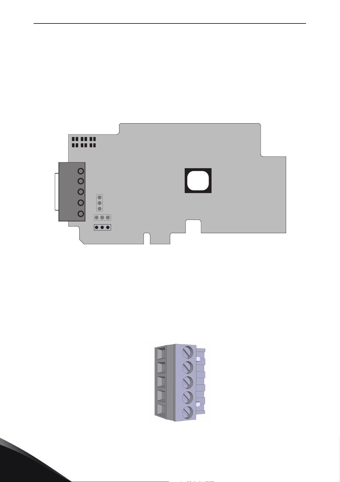
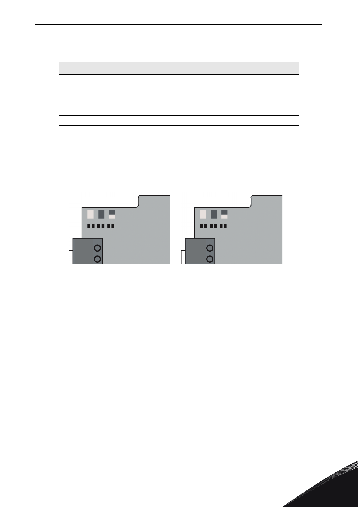
OPTE7 has two different hardware revisions with slightly different layouts. The layout is different in
the LED arrangement and the termination resistor orientation.
The two hardware revisions are marked with different product codes, and this product code can be
seen in the sticker on the top side of the option board (see the location in Figure 6).
The two hardware revisions are 70CVB01817 and 70CVB01555.
1 = V- (GND)
2 = CAN L
3 = SHIELD (shield connector)
4 = CAN H
5 = V+ (24V)
6 = Cable shield grounding option
7 = CAN bus termination jumper
Figure 4. OPTE7 board layout
4
Figure 5. CAN connector
Tel. +358 (0) 201 2121 • Fax +358 (0)201 212 205
Page 15
OPTE7 layout and connections vacon • 12
7086_00
N A MM A N
70CVB01817 70CVB01555
Table 7. CAN connector pinout
Pin Description
1 V-, isolated digital ground
2CAN LO
3 Shield connector
4CAN HI
5 V+ (24V), communication power supply
4.2 LED Indications
The DeviceNet option board includes two LED status indicators next to the connector: network
status (N), and module status (M).
Figure 6. OPTE7 LED indicators
The network status provides information on the network connection status, and the module status
provides information on the DeviceNet module.
24-hour support +358 (0)201 212 575 • Email: [email protected]
4
Page 16

vacon • 13 OPTE7 layout and connections
Table 8. Module status led
LED status Description
OFF No power is supplied to the drive.
Green OPTE7 is operating normally.
Flashing green
Flashing red The OPTE7 has detected a Recoverable Fault.
Red The OPTE7 has detected an Unrecoverable Fault.
LED status Description
OFF
Flashing green
Green The OPTE7 is online and allocated to a master.
Flashing red One or more I/O connections are in the Timed–Out state.
Red
OPTE7 is in the Standby state, or the device needs commissioning due to missing, incomplete or incorrect configuration.
Table 9. Network status led
OPTE7 is not online.
• The device has not completed the Dup_MAC_ID test yet.
• If the Module Status LED is off, the device is not powered.
The OPTE7 has passed the Dup_MAC_ID test, is online, but is
not allocated to a master.
The OPTE7 cannot communicate on the network (Duplicate MAC
ID, or Bus–off).
4
Tel. +358 (0) 201 2121 • Fax +358 (0)201 212 205
Page 17

OPTE7 layout and connections vacon • 14
3
4
5
6
7
3
4
5
6
7
7087_00
70CVB01817 70CVB01555
4.3 Jumpers
The termination resistor jumper location differs on used hardware version. The jumper locations
can be seen from figure below.
Figure 7. Jumper locations
The jumper settings for the CAN bus termination resistor are shown in the figure below.
1
2
A
1
B
1
C
3
A
2
3
3
2
2
3
1
3
2
1
B
70CVB0155570CVB01817
C
3
2
1
7088_00
Figure 8. Termination resistor settings
A = Termination resistor 120 Ohm connected
B = Termination resistor is not connected to the CAN bus. (Factory default setting)
C = Termination resistor is not connected to the CAN bus
The jumper settings for the CAN cable shield grounding are shown in the following figure.
24-hour support +358 (0)201 212 575 • Email: [email protected]
4
Page 18

vacon • 15 OPTE7 layout and connections
3
1
2
3
2
1
1
2
3
A
B
C
9342.emf
Figure 9. Cable shield grounding option
A = CAN connector pin 3 (shield) connected to the drive chassis with a high-impedance RC circuit.
Recommended option when equipotential bonding is poor.
B = CAN connector pin 3 (shield) connected directly into the drive chassis. Recommended option
when equipotential bonding is good. (Factory default setting).
C = CAN connector pin 3 is unconnected.
4
Tel. +358 (0) 201 2121 • Fax +358 (0)201 212 205
Page 19
Installation vacon • 16
M4x55
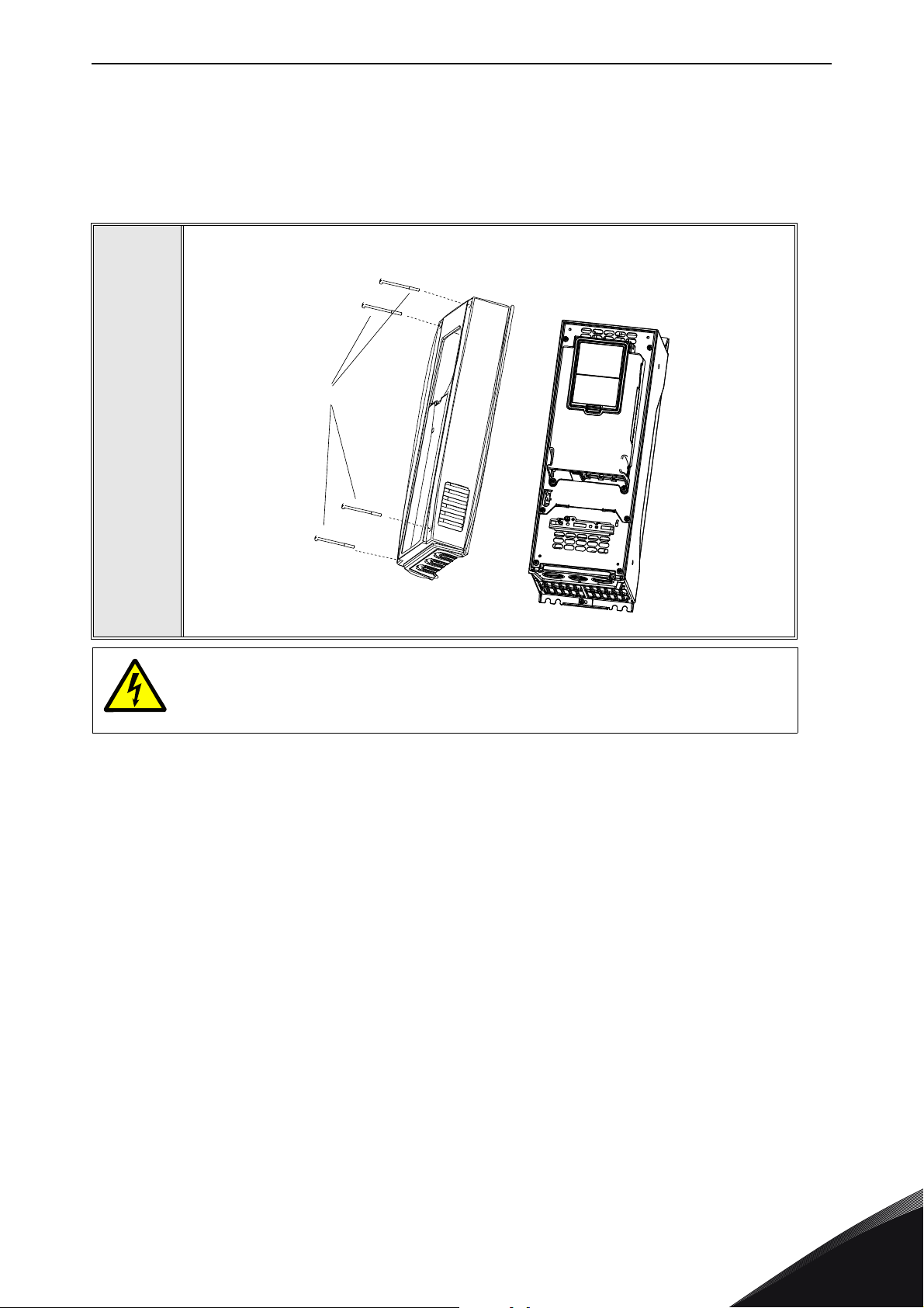
9174.emf
DANGER
5. INSTALLATION
5.1 Installation in Vacon® 100
Open the cover of the AC drive.
1
The relay outputs and other I/O terminals may have a dangerous control voltage
present even when the AC drive is disconnected from mains.
24-hour support +358 (0)201 212 575 • Email: [email protected]
5
Page 20

vacon • 17 Installation
3023.emf
DE
3024.emf
Open the inner cover to reveal the option board slots (C,D,E).
2
3
Install the fieldbus board into slot D or E.
NOTE! Incompatible boards cannot be installed on the drive. Compatible boards
have a slot coding
that enable the placing of the board.
5
Tel. +358 (0) 201 2121 • Fax +358 (0)201 212 205
Page 21
Installation vacon • 18
10
5
5.2 Prepare for use through fieldbus
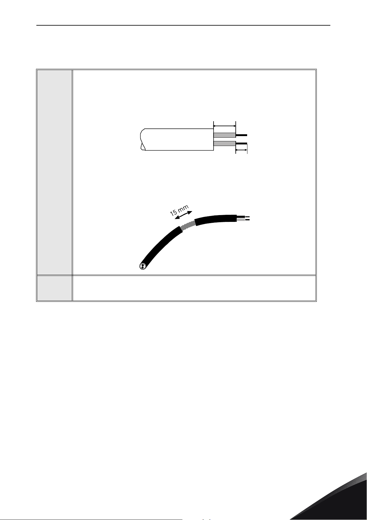
Strip about 15 mm of the fieldbus cable and cut off the grey cable shield.
Remember to do this for both bus cables (except for the last device).
Leave no more than 10 mm of the cable outside the terminal block and strip the
cables at about 5 mm to fit in the terminals.
4
5
Also strip the cable now at such a distance from the terminal that you can fix it to
the frame with the grounding clamp. Strip the cable at a maximum length of 15
mm. Do not strip the aluminum cable shield!
Then connect the cable to its appropriate terminals on the OPTE7 DeviceNet
option board terminal block.
24-hour support +358 (0)201 212 575 • Email: [email protected]
5
Page 22

vacon • 19 Installation
Cable clamp
Using the cable clamp included in the delivery of the drive, ground the shield of
the CAN cable to the frame of the AC drive.
NOTE! This can be done in all drives if there is no difference in PE potential
between the drives. However, if there is PE potential difference then the shield
should be connected to PE only at one point in the system. The shields of the
cables shall be joint but not connected to several PE points with different potential.
6
7
8
If the AC drive is the last device on the bus, the bus termination must be set
with jumper X13.
Unless already done for the other control cables,
cut free the opening on the AC drive cover for the
fieldbus cable (protection class IP21).
NOTE! Cut the opening on the same side you
have installed the board in!
5
Tel. +358 (0) 201 2121 • Fax +358 (0)201 212 205
Page 23

Installation vacon • 20
9202.emf
Fieldbus
cables
Fieldbus cable
= Bus termination
Termination
activated
Ter min ation
activated with
jumper
Termination
deactivated
Vacon 100 Vacon 100 Vacon 100 Vacon 100 Vacon 100
3007.emf
Remount the AC drive cover and run the cable as
shown in picture.
NOTE! When planning the cable runs, remember
to keep the distance between the fieldbus cable
and the motor cable at a minimum of 30 cm. It is
recommended to route the option board cables
away from the power cables as shown in the picture.
9
The bus termination must be set for the first and the last device of the fieldbus
line. See also step 7 on page 19. We recommend that the first device on the bus
and, thus, terminated was the master device.
10
24-hour support +358 (0)201 212 575 • Email: [email protected]
5
Page 24

vacon • 21 Installation
11649_00
11556A_00
5.3 Installation in Vacon® 20
5.3.1 Frames MI1, MI2, MI3
Remove the cable connector lid from the AC
drive.
1
11555A_00
2
3
Select a correct grounding plate and attach it to the
option board mounting frame. The grounding plate is
marked with the supported frame size.
Attach an option board mounting frame to the
drive.
5
Tel. +358 (0) 201 2121 • Fax +358 (0)201 212 205
Page 25
Installation vacon • 22
11558A_00
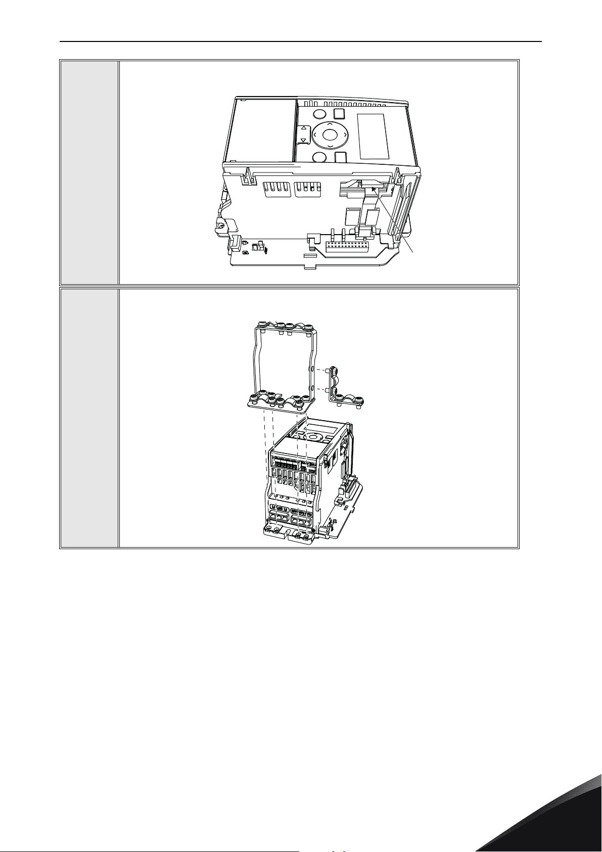
Connect the flat cable from the option board mounting frame to the drive.
4
11557A_00
If a cable strain relief is required, attach the parts as shown in the figure.
5
24-hour support +358 (0)201 212 575 • Email: [email protected]
5
Page 26

vacon • 23 Installation
11650_00
11560A_00
Install the option board to the option board
holder. Make sure that the option board is
securely fastened.
6
Cut free a sufficiently wide opening for the
option board connector.
7
8
Attach the option board cover to the drive. Attach the strain relief cable clamp
with screws if needed.
5
Tel. +358 (0) 201 2121 • Fax +358 (0)201 212 205
Page 27

Installation vacon • 24
13006.emf
11563_00
5.3.2 Frames MI4, MI5
Make sure power is disconnected before opening the cover of the drive.
1a: For MI4: Open the cover.
1
11561_00
1b: For MI5: Open the cover and release the fan connector.
11562_00
Attach the option board support.
2
24-hour support +358 (0)201 212 575 • Email: [email protected]
5
Page 28

vacon • 25 Installation
11564_00
11565_00
Connect the flex cable to option board connector PCB.
3
Connect the option board to connector PCB.
4
5
Attach the option board with connector PCB to the drive and connect the flex cable.
11566_00
5
Tel. +358 (0) 201 2121 • Fax +358 (0)201 212 205
Page 29

Installation vacon • 26
MI 04
MI 05
11567_00
11568_00
Attach a suitable grounding plate to the drive. The grounding plate is marked with
supported frame size.
6
Assemble a clamp on top of the grounding plate on both sides of the option board.
7
24-hour support +358 (0)201 212 575 • Email: [email protected]
5
Page 30

vacon • 27 Installation
11569_00
11570_00
8a: For MI4: Close the cover.
8
8b: For MI5: Remount the fan connector and close the cover.
5
Tel. +358 (0) 201 2121 • Fax +358 (0)201 212 205
Page 31
Installation vacon • 28
13006.emf
13006.emf
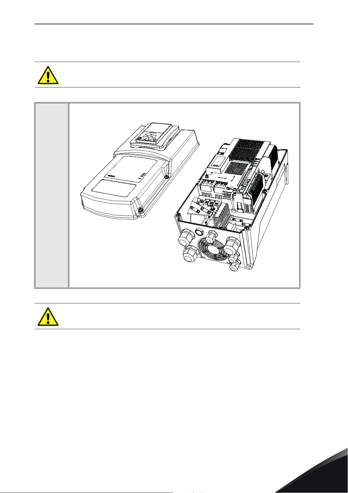
5.4 Installation in Vacon® 20 X and 20 CP
Do not add or replace option boards or fieldbus boards on an AC
drive with the power switched on. This may damage the boards.
Open the cover of the drive.
1
11643_00
MU3 example
The relay outputs and other I/O-terminals may have a dangerous control voltage
present even when the drive is disconnected from mains.
24-hour support +358 (0)201 212 575 • Email: [email protected]
5
Page 32
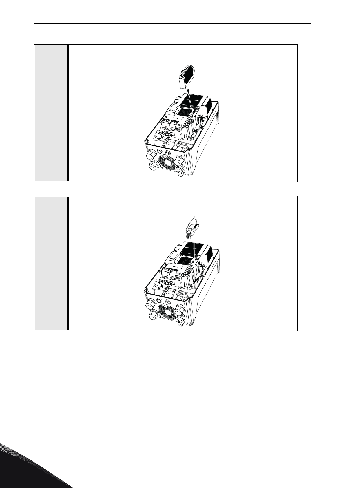
vacon • 29 Installation
7089_00
Remove the option slot cover.
2
3
Install the option board into the slot as shown in the figure.
7090_00
5
Tel. +358 (0) 201 2121 • Fax +358 (0)201 212 205
Page 33
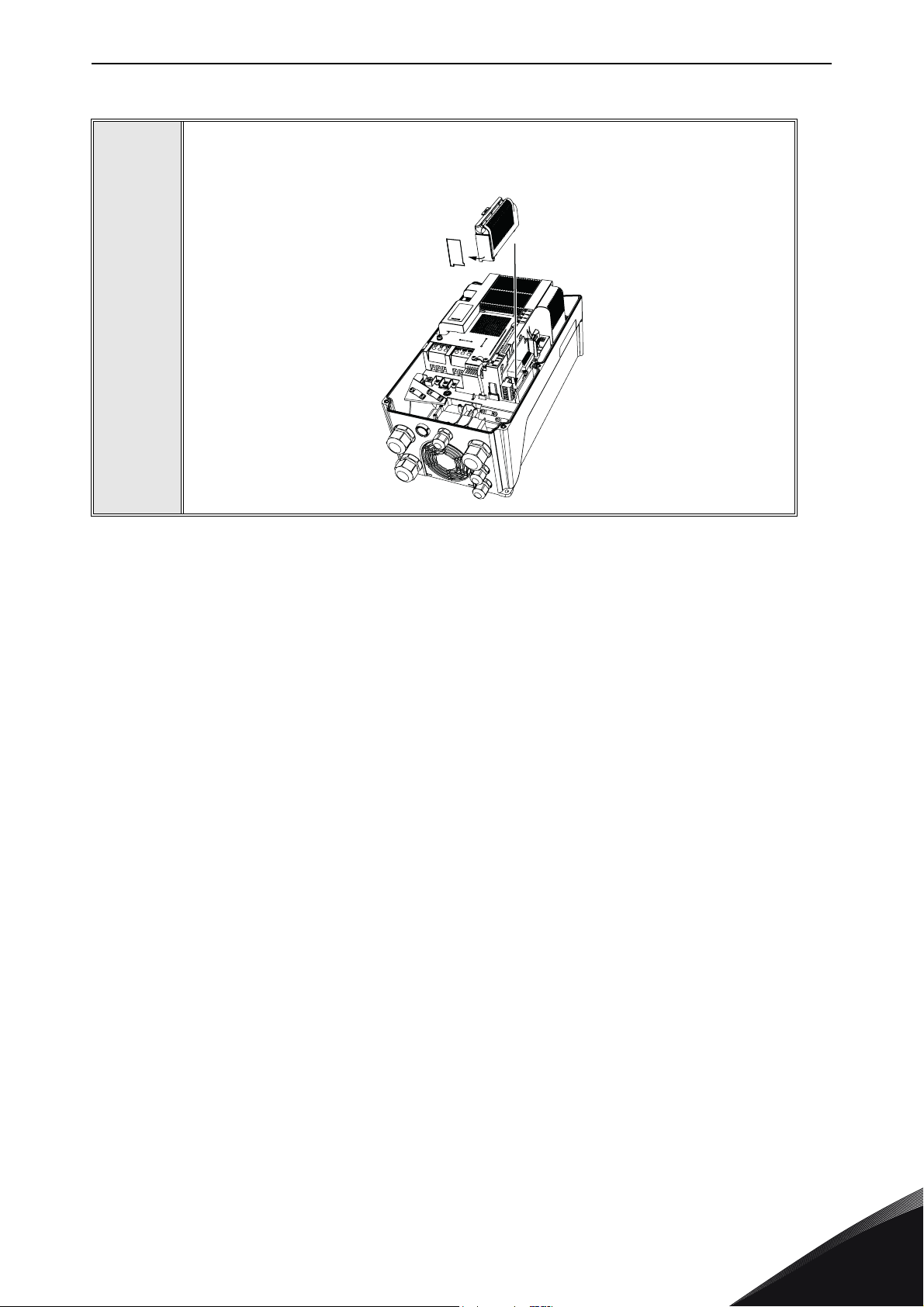
Installation vacon • 30
7091_007091_00
Mount the option slot cover. Remove the plastic opening for the option board
terminals.
4
24-hour support +358 (0)201 212 575 • Email: [email protected]
5
Page 34
vacon • 31 Installation
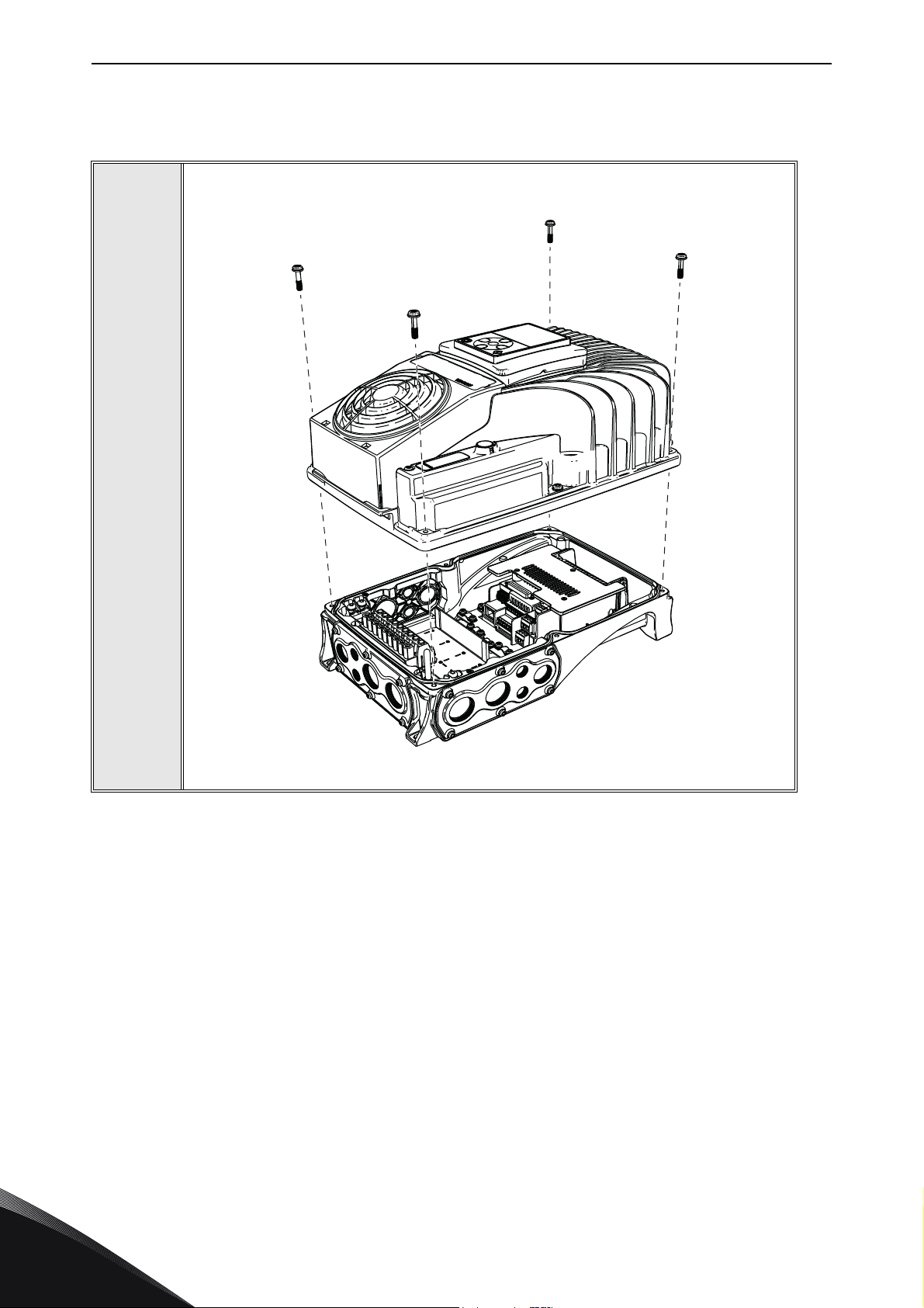
5.5 Installation in Vacon® 100 X (Frames MM4-MM6)
Open the cover of the AC drive.
1
11638_00
5
Tel. +358 (0) 201 2121 • Fax +358 (0)201 212 205
Page 35
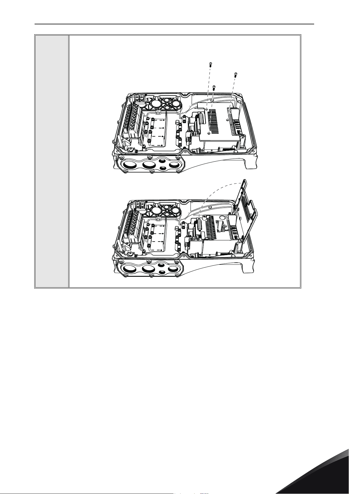
Installation vacon • 32
11639_00
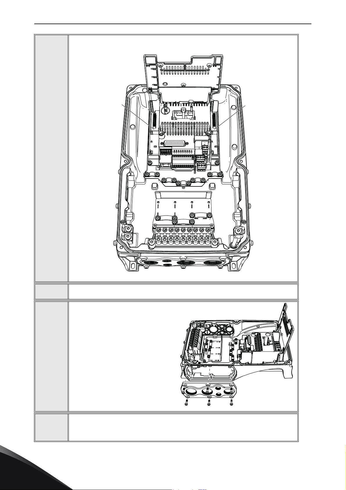
To get access to the option board slots, remove the screws and open the cover of
the control unit.
2
24-hour support +358 (0)201 212 575 • Email: [email protected]
5
Page 36
vacon • 33 Installation
DE
11640_00
11641_00
Install the option board into the correct slot, D or E.
3
4
5
6
Close the option board cover.
Remove the cable entry plate. If you
installed the option board in the slot
D, use the cable entry plate on the
right side. If you installed the option
board in the slot E, use the cable entry plate on the left side.
NOTE! The cable entry plate at the
bottom of the drive is used only for
mains and motor cables.
Open the necessary holes in the cable entry plate. Do not open the other holes.
See the Vacon
® 100X Installation Manual for the dimensions of the holes.
5
Tel. +358 (0) 201 2121 • Fax +358 (0)201 212 205
Page 37
Installation vacon • 34
11642_00
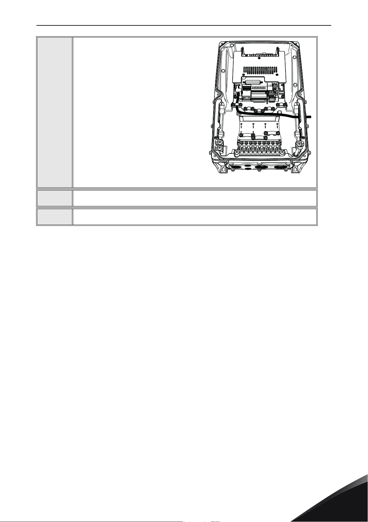
Attach a cable gland on the hole in the cable entry plate. Pull the fieldbus cable
through the hole.
NOTE! The fieldbus cable must go through
the correct cable entry plate to avoid going
near the motor cable.
7
8
9
Put the cable entry plate back.
Close the cover of the AC drive.
24-hour support +358 (0)201 212 575 • Email: [email protected]
5
Page 38

vacon • 35 Commissioning
6. COMMISSIONING
6.1 Parameter view
Table 10. Parameter view
Name Default Range Description
MAC ID 63 0...63
125 kbit/s
Baud rate 125 kbit/s
Output
assembly
Input
assembly
21
71
250 kbit/s
500 kbit/s
6.2 Monitor view
20
21
23
25
101
111
70
71
73
75
107
117
Slave address. Valid device addresses are in the
range of 0 to 63 decimal.
Communication speed
Output assembly used by the polled connection.
Setting of this value via panel is not allowed when
the I/O connection is established. If setting of this
value fails, the value is not updated.
Input assembly used by the polled connection. Setting of this value via panel is not allowed when the
I/O connection is established! If setting of this value
fails, the value is not updated.
Table 11. Monitor view
Name Range Description
DeviceNet Status Y.X
Table 12. DeviceNet status
DeviceNet Status Description
0 Non-existent
1 Configuring
3 Established
4 Timeout
Y = Message counter
X = DeviceNet status
6
Tel. +358 (0) 201 2121 • Fax +358 (0)201 212 205
Page 39

Commissioning vacon • 36
6.3 Software info view
Table 13. Software info view
Number Name Range Description
1
2 Board status Shows the status of the option board
Version
number
Version number of the software in the option
board
6.4 Fieldbus parametrisation
The following chapter describes briefly, how to parametrise the AC drive in order for the motor to
be controllable via fieldbus. These instructions are written for some basic applications. For more
information, please consult the application-specific manual.
In order for the AC drive to accept commands from the fieldbus network, the control place of the AC
drive has to be set to fieldbus. The default value of the parameter “Control Place” is usually I/O. Note
that if the control unit firmware is updated, the default settings are restored. In addition, some
applications may have the remote speed reference selection set by default to other than fieldbus. In
these cases, the speed reference selection must be set to fieldbus, in order for the speed reference
to be controlled via fieldbus.
In DeviceNet, the bits NetCtrl, NetRef and NetProc must be set in order for the option board to send
commands / reference setpoint values to the AC drive. The bits Ctrl From Net and Ref From Net can
be read to determine the actual control / reference place. Note that these bits are valid only if
NetCtrl / NetRef bits are also set.
NOTE! The motor control mode should be selected to support the used process and profile.
6.4.1 Fieldbus control and basic reference selection
The following tables list some of the parameters related to fieldbus control in case of three standard
applications, the Vacon
specific manuals for more detailed information.
Parameter
name
Control mode 600
Remote control
place
Local / remote 211 0 = Remote 0 P 3.2.2 0xA0, 0x01, 0xD3
Fieldbus ref.
sel.
® 100, Vacon® 20 and Vacon® 20X, for use via fieldbus. See the application-
Table 14. Parametrisation for Vacon
ID Value Default
0 = Frequency
1 = Speed
2 = Torque
172
122 3 = Fieldbus 3 P 3.3.1.10 0xA0, 0x01, 0x7A
1 = Fieldbus
CTRL
® 100 (standard application)
Panel
Tree
0 P 3.1.2.1 0xA0, 0x03, 0x58
0 P 3.2.1 0xA0, 0x01, 0xAC
Class, Instance, Attribute
24-hour support +358 (0)201 212 575 • Email: [email protected]
6
Page 40

vacon • 37 Commissioning
Table 15 . Para metris ation for Vacon
Parameter
name
Motor control
mode
Rem. control
place 1 sel.
Local / remote 211 0 = Remote 0 P 2.5 0xA0, 0x01, 0xD3
Rem. control
place 1 freq. ref.
sel.
Parameter
name
Motor control
mode
Control place
selection
Local / remote 211 0 = Remote 0 P 3.2.2 0xA0, 0x01, 0xD3
Frequency ref.
sel.
ID Value Default
600
172
117 3 = Fieldbus 7 P 3.3 0xA0, 0x01, 0x75
Table 16. Parametrisation for Vacon
600
125 2 = Fieldbus 0 P 1.11 0xA0, 0x01 0x7D
1819 5 = Fieldbus 5-7 P 1.12 0xA0, 0x08, 0x1B
0 = Frequency
1 = Speed
1 = Fieldbus
CTRL
ID Value Default
0 = Frequency
1 = Speed
® 20 (standard application)
Panel
Tree
0 P 1.8 0xA0, 0x03, 0x58
0 P 2.1 0xA0, 0x01, 0xAC
Class, Instance, Attribute
® 20X (standard application)
Panel
Tree
0 P 8.1 0xA0, 0x03, 0x58
Class, Instance, Attribute
6.4.2 Torque control parametrisation
Some extra parametrisation has to be made in order to control the frequency control with torque
control. The following instructions are for the Vacon 100 application, see the application-specific
manual for more detailed information.
• Motor control mode (ID 600) should be configured to “Torque control (Open Loop)” (2).
To configure the drive to use correct torque reference, parameter “Torque Reference Selection”
should be selected to ProcessDataIn1 (9). This can be done with:
• PC-tool or panel (P 3.3.2.1) / ID 641
• Vendor Parameter Object TorqueRefSel (Class 0xA0, Instance 0x03, Attribute 0x81)
6.4.3 Process data mapping and default settings
In DeviceNet, output instances 107 and 117 (Chapter 7.1.2.5 and 7.1.2.6), can be used to send
process data to network. This data is selectable in the application and the default settings vary
between drives. Refer to the application manual for details. The following tables show the default
values for Vacon 100, Vacon 20X and Vacon 20 applications.
6
Tel. +358 (0) 201 2121 • Fax +358 (0)201 212 205
Page 41
Commissioning vacon • 38
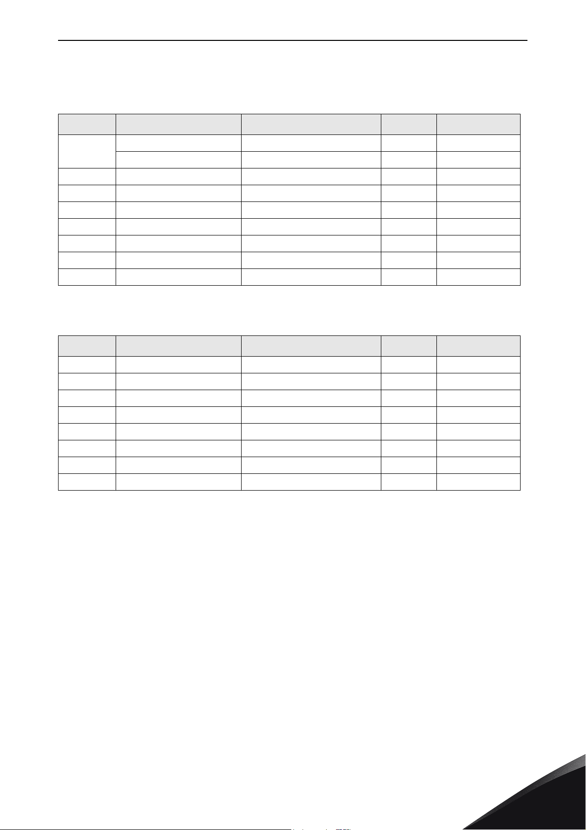
Table 17. Process data output mapping defaults for Vacon® 100 and Vacon® 20X (standard
applications)
PD Out AC Drive Mapped Application Data Unit Scale
1
2 Vacon 100 & Vacon 20X Motor Speed rpm 1 rpm
3 Vacon 100 & Vacon 20X Motor Current A Varies
4 Vacon 100 & Vacon 20X Motor Torque % 0.1%
5 Vacon 100 & Vacon 20X Motor Power % 0.1%
6 Vacon 100 & Vacon 20X Motor Voltage V 0.1 V
7 Vacon 100 & Vacon 20X DC Link Voltage V 1 V
8 Vacon 100 & Vacon 20X Last Active Fault Code - -
Table 18. Process data output mapping defaults for Vacon
PD Out AC Drive Mapped Application Data Unit Scale
1 Vacon 20 Frequency Reference Hz 0.01 Hz
2 Vacon 20 Output Reference Hz 0.01 Hz
3 Vacon 20 Motor Speed rpm 1 rpm
4 Vacon 20 Motor Voltage V 0.1 V
Vacon 100 Output Frequency Hz 0.01 Hz
Vacon 20X Output Current A Varies
® 20 (standard application)
5Vacon 20 Motor Torque%0.1%
6 Vacon 20 Motor Current A Varies
7 Vacon 20 Motor Power % 0.1%
8 Vacon 20 DC Link Voltage V 1 V
24-hour support +358 (0)201 212 575 • Email: [email protected]
6
Page 42

vacon • 39 DeciveNet interface
7. DECIVENET INTERFACE
Vacon supports two types of DeviceNet messaging. They are I/O Messaging and Explicit Messaging.
7.1 I/O messaging
I/O polling messages are for time-critical, control-oriented data. The messages are transferred
between the devices all the time and they are used for continuous control of the AC drive. They
provide a dedicated, special-purpose communication path between a producing application
(master) and one or more consuming applications (slaves). They are exchanged across single or
multi-cast connections, typically using high priority identifiers. I/O polling messages contain no
protocol in the 8-byte data field. The meaning of the message is implied by the connection ID (CAN
identifier). Before messages are sent using these IDs, both the device sending and receiving them
must be configured. The configuration contains the source and destination object attribute
addresses for the master and the slave.
Data (Output Assembly)
Master Slave
Data (Input Assembly)
Figure 10. DeviceNet I/O messaging
The contents of the data message are chosen by input and output assemblies. These assemblies
can be selected via panel or by setting Produced Connection Path (14) and Consumed Connection
Path (16) attributes in DeviceNet connection object. Note that setting of instances is not allowed via
panel, if I/O connection is open. See Chapter 10.2 for more details. Chapter 7.1.2 describes all
supported input and output assemblies.
7.1.1 Connection behaviour
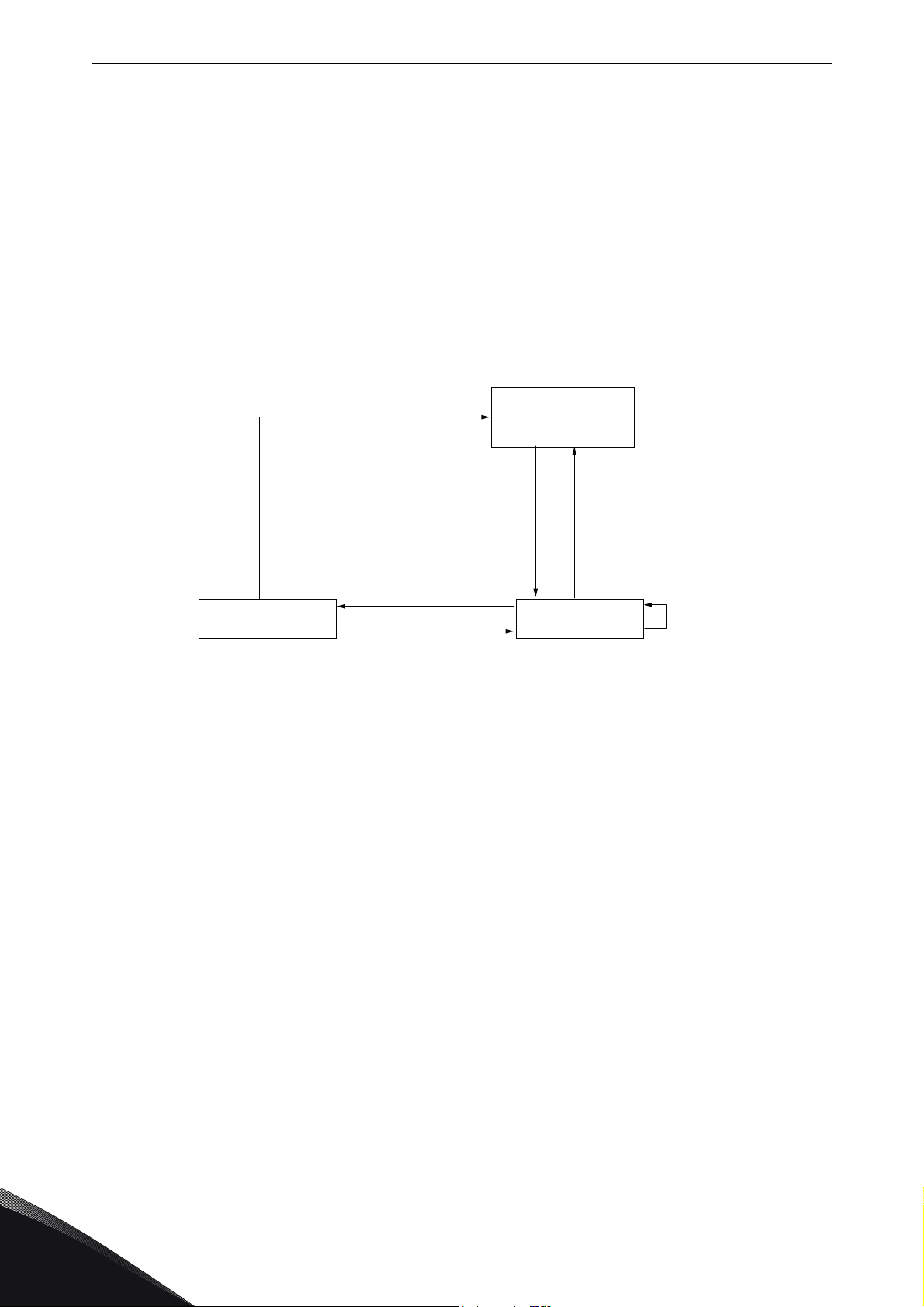
The following figure provides a general overview of the behaviour associated with an I/O connection
object (instance type attribute = I/O).
7080_UK
7
Tel. +358 (0) 201 2121 • Fax +358 (0)201 212 205
Page 43

DeciveNet interface vacon • 40
7081_UK
Non-existent
Delete from any state
Get_Attribute/
Set_Attribute/
Apply_Attributes
Get_Attribute/Set_Attribute/
Apply_Attributes/Reset/
Message Produced/Consumed
Inactivity/Watchdog
Timeout &
Watchdog_timeout_action=
Transition to Timed Out
Configuring
Create
Apply_Attributes
Delete
Reset
Established
Timed Out
Figure 11. I/O Connection Object State Transition Diagram
By default, Expected Packet Rate (EPR) of I/O connection is set to zero, meaning that no transition
to Timed Out state will occur. If EPR Timeout is set to other than zero, timeout will occur after four
times Expected Packet Rate (4 * EPR). For example value 1000 (ms) will result in timeout after four
seconds.
7.1.2 Input and Output Assemblies
The following chapters describe the used input/output assemblies.
Table 19. Supported Input / Output Assemblies
Name Profile Number Type
20 Output
Basic Speed Control CIP
70 Input
21 Output
Extended Speed Control (default) CIP
71 Input
23 Output
Extended Speed and Torque Control CIP
73 Input
25 Output
Process Control CIP
75 Input
101 Output
Dynamic Process Control Vacon
107 Input
Bypass Control Output Vacon
111 Output
117 Input
24-hour support +358 (0)201 212 575 • Email: [email protected]
7
Page 44

vacon • 41 DeciveNet interface
7.1.2.1 20/70 Basic Speed Control
Basic speed control is the most basic control type, where the run direction is limited to only forward,
and only Run and Fault reset commands are supported. Speed reference is given in revolutions per
minute. The run/stop commands work as described in Table 39, with Run Rev always interpreted as
zero. In this mode, the control supervisor attributes NetCtrl and NetRef bits are always set to one.
Table 20. Basic Speed Control Instance descriptions
Instance Byte Bit7 Bit6 Bit5 Bit4 Bit3 Bit2 Bit1 Bit0
Basic Speed Control Output
0
Fault Reset Run Fwd
20
70
7.1.2.2
1
2 Speed Reference (Low Byte)
3 Speed Reference (High Byte)
Basic Speed Control Input
0
1
2 Speed Actual (Low Byte)
3 Speed Actual (High Byte)
Table 21. Basic Speed Control Attribute descriptions
Attribute Unit Range Note
Speed Reference rpm 0-32767
Speed Actual rpm 0-32767
21/71 Extended Speed Control (default)
Running1 Faulted
7
Extended speed control provides more functionality over the basic speed control. NetRef and
NetCtrl bits must be set to one, in order for the commands and reference values to be sent to the
AC drive. When these bits are set, the actual control/reference place can be read from "Ctrl From
Net" and "Ref From Net" bits. Run Forward and Run Reverse bits are used to control the direction
of the motor. See Table 39 for complete description of the run commands.
Tel. +358 (0) 201 2121 • Fax +358 (0)201 212 205
Page 45

DeciveNet interface vacon • 42
Table 22. Basic Speed Control Instance descriptions
Instance Byte Bit7 Bit6 Bit5 Bit4 Bit3 Bit2 Bit1 Bit0
Extended Speed Control Output
21
0
1
2 Speed Reference (Low Byte)
3 Speed Reference (High Byte)
NetRef NetCtrl
Extended Speed Control Input
Fault
Reset
Run Rev Run Fwd
At Ref-
0
erence
71
Speed Reference rpm 0-32767
Speed Actual rpm 0-32767
7.1.2.3 23/73 Extended Speed and Torque Control
Extended speed and torque assemblies can be used when torque reference is needed.
Torque Reference is converted from
instance 2, attribute 24), to a %-value for the AC drive. This value is sent in ProcessDataIn1 for the
control unit when NetRef bit is set. Therefore, ProcessDataIn1 should be selected as torque
reference selection. See the application manual or Chapter 6.4.2 for more details.
1Drive State
2 Speed Actual (Low Byte)
3 Speed Actual (High Byte)
Table 23. Extended Speed Control Attribute descriptions
Attribute Unit Range Note
Drive State - 0-7 See Chapter 7.1.3
Ref
from
Net
Ctrl
from
Net
τ (Nm)/2n
, where n is the torque scale value (AC/DC Drive object,
Rea
dy
Runnin
g2
(Rev)
Running1 Warning Faulted
Table 24. Extended Speed and Torque Control Instance descriptions
Instance Byte Bit7 Bit6 Bit5 Bit4 Bit3 Bit2 Bit1 Bit0
Extended Speed and Torque Control Output
0
1
23
24-hour support +358 (0)201 212 575 • Email: [email protected]
2 Speed Reference (Low Byte)
3 Speed Reference (High Byte)
4 Torque Reference (Low Byte)
5 Torque Reference (High Byte)
NetRef NetCtrl
Fault
Reset
Run Rev Run Fwd
7
Page 46

vacon • 43 DeciveNet interface
Table 24. Extended Speed and Torque Control Instance descriptions
Instance Byte Bit7 Bit6 Bit5 Bit4 Bit3 Bit2 Bit1 Bit0
Extended Speed and Torque Control Input
At Ref-
0
erence
1Drive State
73
Speed Reference rpm 0-32767
Speed Actual rpm 0-32767
Torque Reference
Torq ue Act ual
2 Speed Actual (Low Byte)
3 Speed Actual (High Byte)
4 Torque Actual (Low Byte)
5 Torque Actual (High Byte)
Table 25. Extended Speed and Torque Control Attribute descriptions
Attribute Unit Range Note
Drive State - 0-7 See Chapter 7.1.3
from
Net
Nm/2
Nm/2
Ref
Torque Scale
Torque Scale
Ctrl
from
Net
-32768...32767
-32768...32767
Rea
dy
Runnin
g2
(Rev)
Running1 Warning Faulted
7.1.2.4 25/75 Extended Process Control
Extended process control assemblies can be used to send process reference value directly to the
application. The Process Reference value destination can be selected with Drive Mode byte
according to Table 28. This should be configured in application as the receiving input. Process Actual
value is always mapped to ProcessDataOut1. Note that process reference value is sent to drive only
when NetProc bit is set.
Table 26. Extended Process Control Instance descriptions
Instance Byte Bit7 Bit6 Bit5 Bit4 Bit3 Bit2 Bit1 Bit0
Extended Process Control Output
25
0
1Drive Mode
2 Speed Reference (Low Byte)
3 Speed Reference (High Byte)
NetProc
NetRef NetCtrl
Fault
Reset
Run Rev Run Fwd
7
4 Process Reference (Low Byte)
5 Process Reference (High Byte)
Tel. +358 (0) 201 2121 • Fax +358 (0)201 212 205
Page 47

DeciveNet interface vacon • 44
Table 26. Extended Process Control Instance descriptions
Instance Byte Bit7 Bit6 Bit5 Bit4 Bit3 Bit2 Bit1 Bit0
Extended Process Control Input
At Ref-
0
erence
1Drive State
75
Speed Reference rpm 0-32767
Speed Actual rpm 0-32767
Process Reference - - See Table 28
Process Actual - - ProcessDataOut1
2 Speed Actual (Low Byte)
3 Speed Actual (High Byte)
4Process Actual (Low Byte)
5Process Actual (High Byte)
Table 27. Extended Process Control Attribute descriptions
Attribute Unit Range Note
Drive Mode - - See Table 28
Drive State - 0-7 See Chapter 7.1.3
Ref
from
Net
Ctrl
from
Net
Rea
dy
Runnin
g2
(Rev)
Running1 Warning Faulted
Table 28. Drive Mode selection in Process Control
Drive
Mode
0ProcessDataIn1
4ProcessDataIn2
Other Not valid
7.1.2.5 101/107 Vendor Dynamic Process Control
These assemblies can be used to send/receive process data directly to and from the application. The
FB Speed Reference and the FB Speed Actual values are given as percentage of the minimum and
maximum frequency. The control and status words are still given as CIP standard specific values.
Process Reference Mapping
24-hour support +358 (0)201 212 575 • Email: [email protected]
7
Page 48
vacon • 45 DeciveNet interface
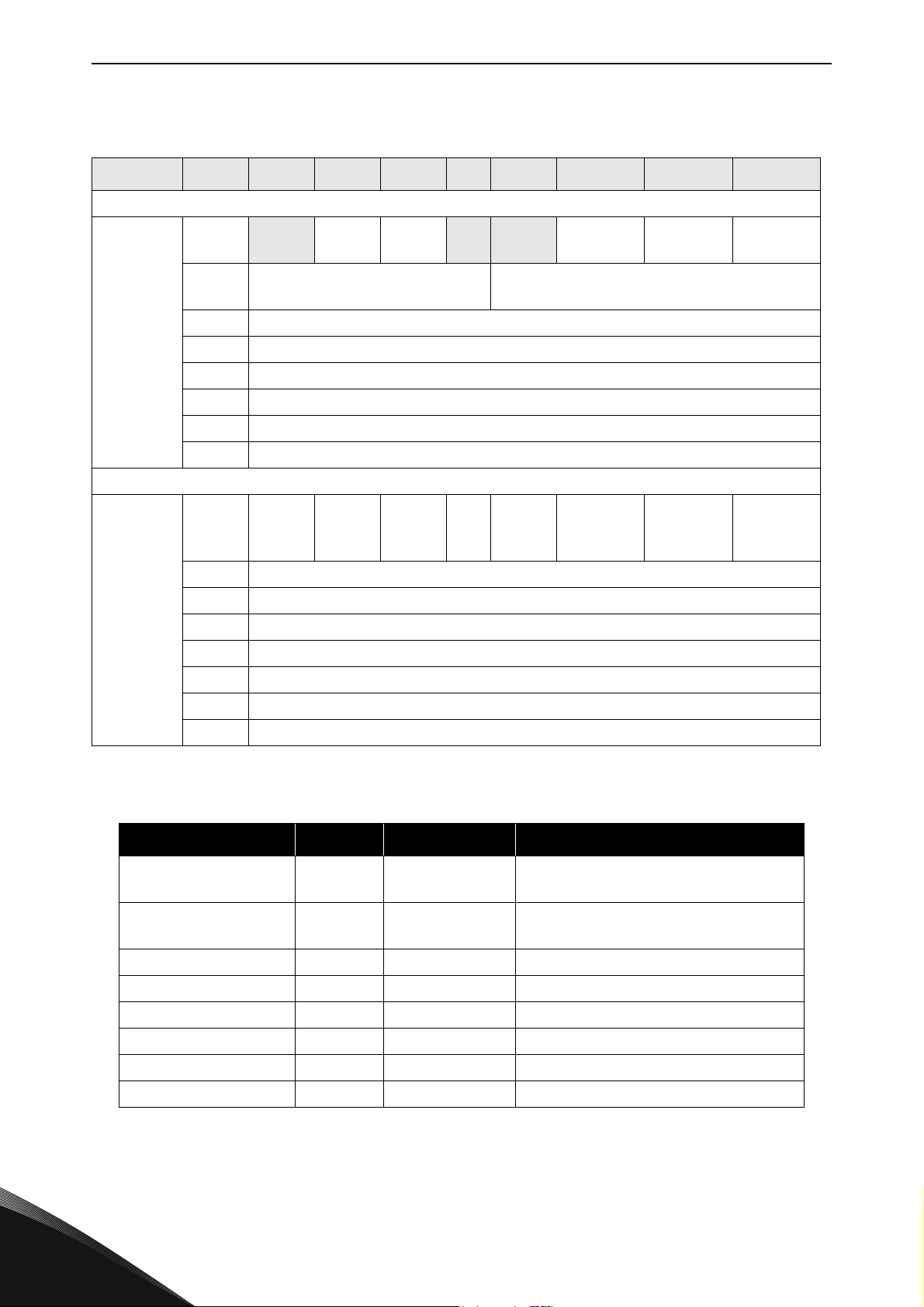
Table 29. Vendor Dynamic Process Control Instance descriptions
Instance Byte Bit7 Bit6 Bit5 Bit4 Bit3 Bit2 Bit1 Bit0
Dynamic Process Control Output
101
0
1
2 FB Speed Reference (Low Byte)
3 FB Speed Reference (High Byte)
4 ProcessDataIn1 (Low Byte)
5 ProcessDataIn1 (High Byte)
6 ProcessDataIn2 (Low Byte)
7 ProcessDataIn2 (High Byte)
Process Data 1 Selector (bits
NetRef NetCtrl
4-7)
Dynamic Process Control Input
Process Data 2 Selector (bits 0-3)
Fault
Reset
Run Rev Run Fwd
At Ref-
0
erence
1Drive State
2 FB Speed Actual (Low Byte)
107
FB Speed Reference %
FB Speed Actual %
ProcessDataIn1 - -
3 FB Speed Actual (High Byte)
4ProcessDataOut1 (Low Byte)
5 ProcessDataOut1 (High Byte)
6ProcessDataOut2 (Low Byte)
7 ProcessDataOut2 (High Byte)
Table 30. Vendor Dynamic Process Control Attribute descriptions
Attribute Unit Range Note
Ref
from
Net
Ctrl
from
Net
0-10000
(100.00%)
0-10000
(100.00%)
Rea
dy
Runnin
g2
(Rev)
Running1 Warning Faulted
7
ProcessDataIn2 - ProcessDataOut1 - - See Table 31
ProcessDataOut2 - - See Table 31
Process Data Selector - - See Table 31
Drive State - 0-7 See Chapter 7.1.3
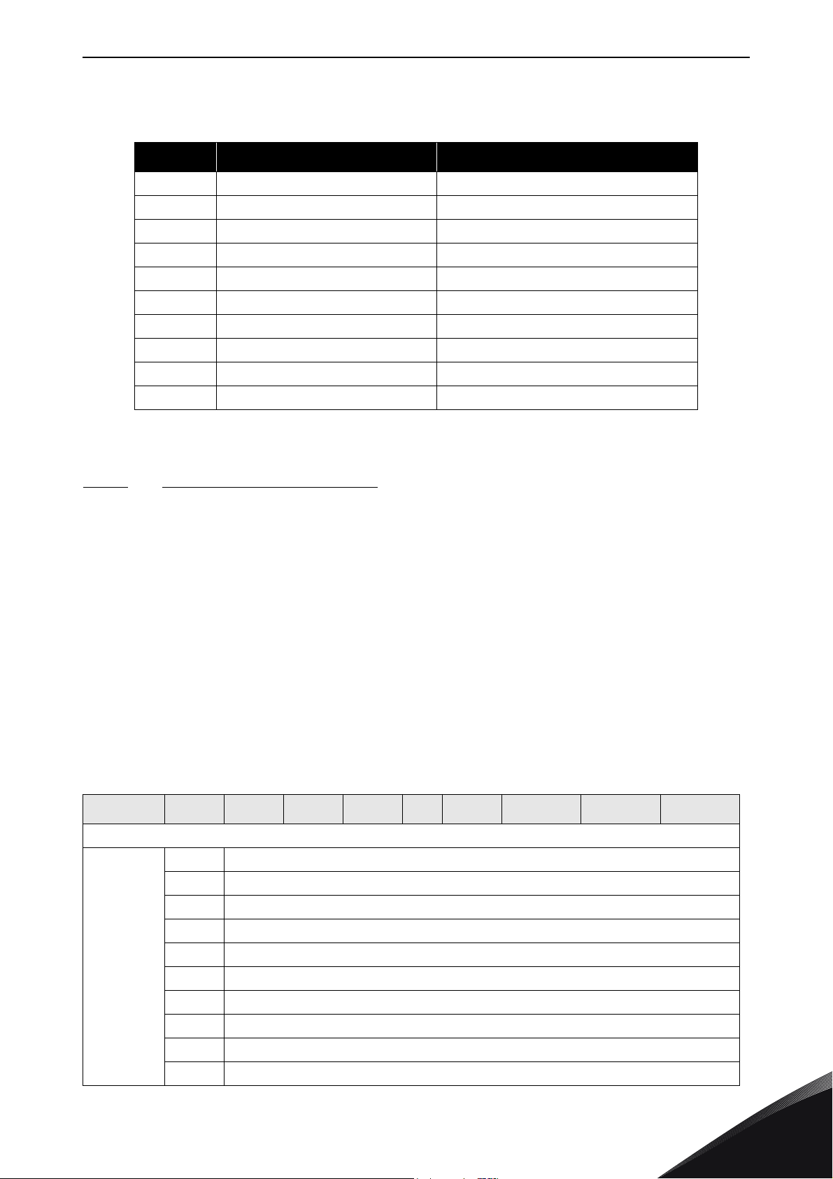
Process data selector bits can be used to select what content is mapped to ProcessDataOut 1 & 2
(bytes 4-7). The following table describes what values in these fields correspond to which process
data items.
Tel. +358 (0) 201 2121 • Fax +358 (0)201 212 205
Page 49
DeciveNet interface vacon • 46
Table 31. Process Data Selector 1 & 2 description
Value Bytes 4-5 of instance 107 Bytes 6-7 of instance 107
0 * Speed Actual [%] Speed Actual [%]
1ProcessDataOut1 ProcessDataOut1
2ProcessDataOut2 ProcessDataOut2
3ProcessDataOut3 ProcessDataOut3
4ProcessDataOut4 ProcessDataOut4
5ProcessDataOut5 ProcessDataOut5
6ProcessDataOut6 ProcessDataOut6
7ProcessDataOut7 ProcessDataOut7
8ProcessDataOut8 ProcessDataOut8
Other ProcessDataOut1 ProcessDataOut2
* If both Process Data selectors are 0, bytes 4-5 are ProcessDataOut1 and bytes 6-7 are
ProcessDataOut2.
7.1.2.6
These assemblies can be used to bypass the CIP standard assemblies, and control the AC drive
application directly. The FB Speed Reference and the FB Speed Actual values are given as
percentage of the minimum and maximum frequency. The control and status words are applicationspecific values. Table 34 and Table 35 describe the control word, and Table 36 and Table 37 describe
the fieldbus status words that are commonly used. Note that not all applications support all bits,
and so application-specific manuals should be consulted.
Instance Byte Bit7 Bit6 Bit5 Bit4 Bit3 Bit2 Bit1 Bit0
111/117 Vendor Bypass Control
Table 32. Vendor Bypass Control Instance descriptions
Bypass Control Output
0-1 Control Word
2-3 FB Speed Reference
4-5 ProcessDataIn1
6-7 ProcessDataIn2
111
8-9 ProcessDataIn3
10-11 ProcessDataIn4
12-13 ProcessDataIn5
14-15 ProcessDataIn6
16-17 ProcessDataIn7
18-19 ProcessDataIn8
24-hour support +358 (0)201 212 575 • Email: [email protected]
7
Page 50
vacon • 47 DeciveNet interface
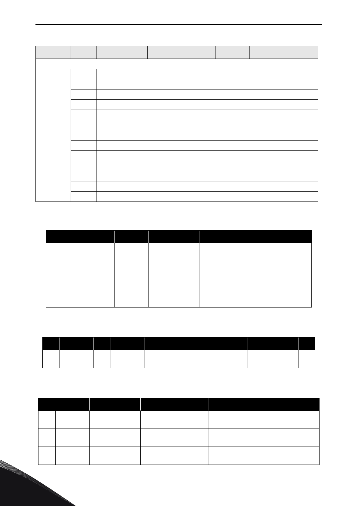
Table 32. Vendor Bypass Control Instance descriptions
Instance Byte Bit7 Bit6 Bit5 Bit4 Bit3 Bit2 Bit1 Bit0
Bypass Control Input
0-1 Status Word
2-3 FB Speed Actual [%]
4-5 FB Speed Actual [rpm]
6-7 Speed Actual With Slip
8-17 Reserved
18-19 ProcessDataOut1
117
FB Speed Reference %
FB Speed Actual %
FB Speed Actual rpm -32768…32767
Speed Actual With Slip rpm 0-32767 Slip compensated RPM value.
20-21 ProcessDataOut2
22-23 ProcessDataOut3
24-25 ProcessDataOut4
26-27 ProcessDataOut5
28-29 ProcessDataOut6
30-31 ProcessDataOut7
32-33 ProcessDataOut8
Table 33. Vendor Bypass Control Attribute descriptions
Attribute Unit Range Note
0-10000
(100.00%)
0-10000
(100.00%)
Ramp output frequency converted to
rpm.
7
Table 34. Fieldbus Control Word
15 14 13 12 11 10 9 8 7 6 5 4 3 2 1 0
---
Bit Name Description 0 1
12 ESTP Emergency Stop
11 JOG2 Jogging Request
10 JOG1 Jogging Request
ESTPJOG2JOG1BREFBCTRLZREFFRMPQRMPSTPM2STPM1FRS
T
Table 35. Fieldbus Control Word description
Request as fast stop
as possible
Select jogging with
reference 2
Select jogging with
reference 1
Tel. +358 (0) 201 2121 • Fax +358 (0)201 212 205
- Emergency Stop
- Select ref2 jogging
- Select ref1 jogging
DIR
STR
T
Page 51
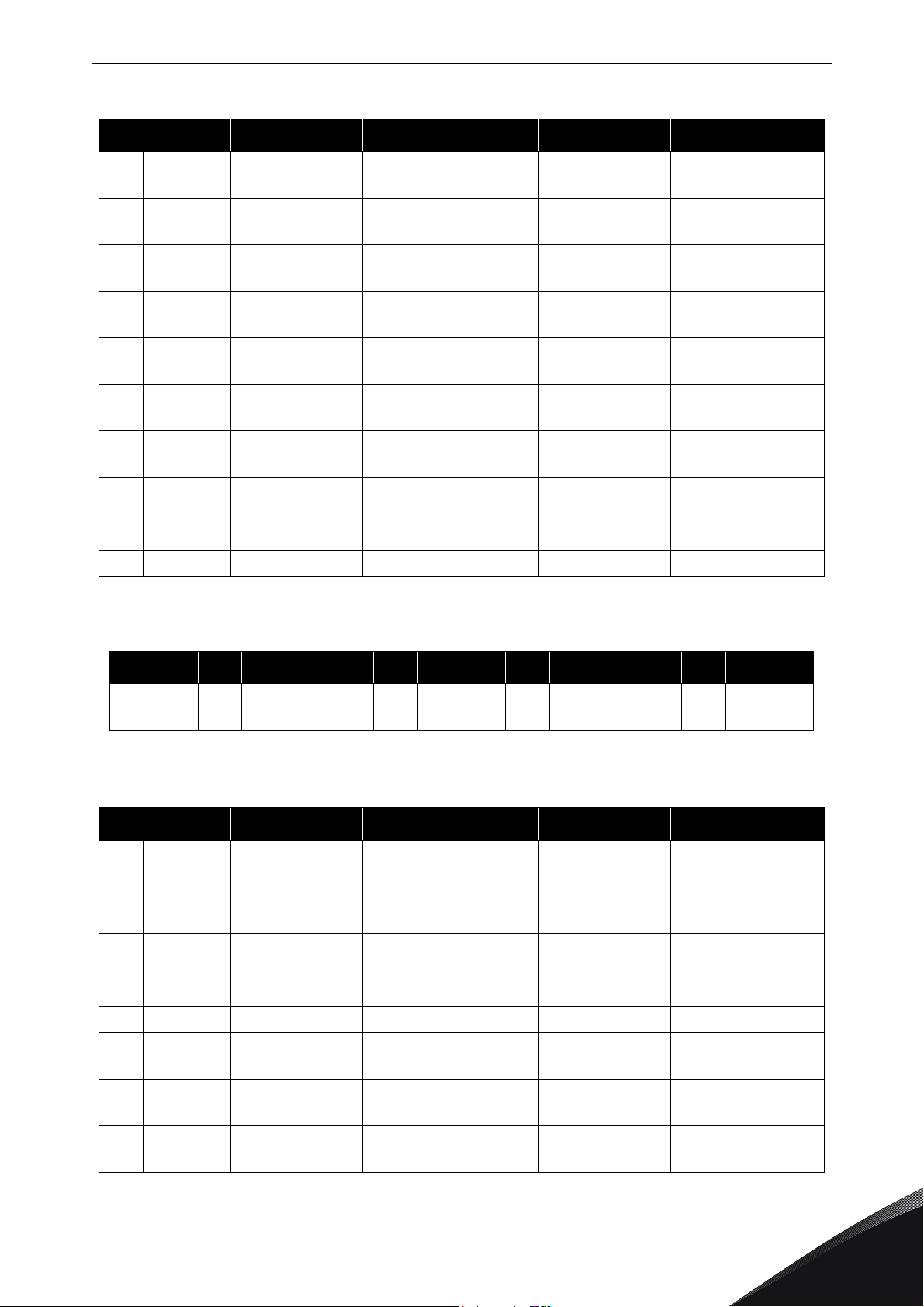
DeciveNet interface vacon • 48
Table 35. Fieldbus Control Word description
Bit Name Description 0 1
9 BREF Bus Reference
8BCTRL Bus Control
7 ZREF Zero Ref
6 FRMP Ramp Freeze
5QRMP
4 STPM2 Stop Mode2 Stop mode ramping -
3 STPM1 Stop Mode1 Stop mode coasting -
2FRST Fault Reset
1 DIR Direction Rotation direction Clockwise Counterclockwise
0 STRT Start / Stop Start / Stop request Stop Run
Quick Ramp
Time
Force reference to
fieldbus
Force fieldbus control
active
Force reference to
zero
Freeze ramp
generator
Use quick ramp time
Request fault reset
from drive
Selected
reference place
Selected control
place
-
-
Normal ramp
time
-
Force fieldbus
reference
Force fieldbus
control
Force reference to
zero
Freeze ramp
generator
Quick Ramp Time
Stop By Ramp
Mode
Coasting Stop
Mode
Request reset from
drive
Table 36. Fieldbus Status Word
15 14 13 12 11 10 9 8 7 6 5 4 3 2 1 0
--------
Table 37. Fieldbus Status Word description
Bit Name Description 0 1
7 FRDY Flux Ready
6 ZSPD Zero Speed
5ATREFAt Reference
4 ALARM Alarm Alarm indication - Drive is in alarm
3 FLT Faulted Drive fault indication - Drive is faulted
2DIR Direction
1RUN Run
0RDY Ready
Motor magnetisation
Motor is running at
zero speed
Reference frequency
is reached
Motor running
direction
Motor running
information
Drive readiness
information
FRDYZSPDATREFALA
is ready
FLT DIR RUN RDY
RM
-Flux Ready
-
- Reference reached
Clockwise Counterclockwise
Stopped Running
-Ready
Zero speed
condition
24-hour support +358 (0)201 212 575 • Email: [email protected]
7
Page 52
vacon • 49 DeciveNet interface
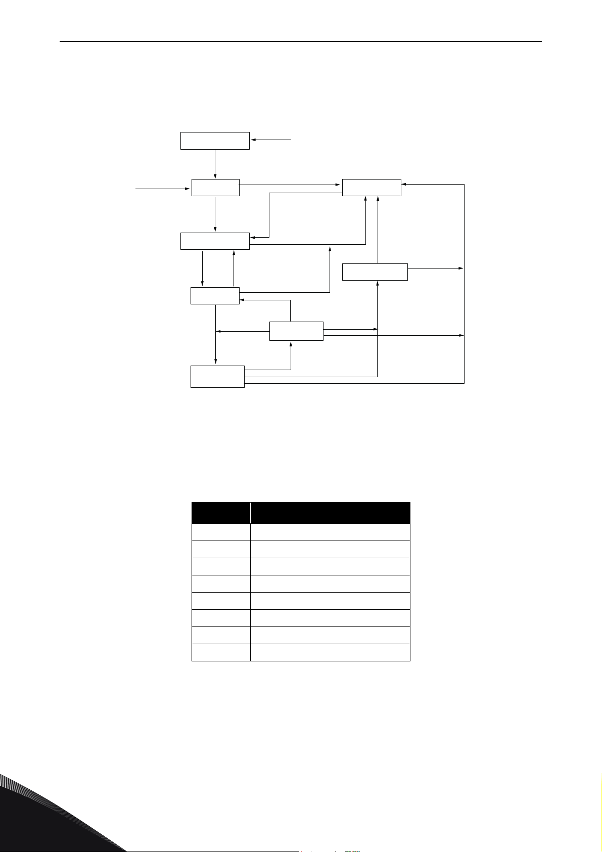
7.1.3 Control Supervisor Behaviour
The State Transition Diagram provides a graphical description of the states and the corresponding
state transitions for the control supervisor.
Non-existent
Switch On
Reset
Initialisation Complete
Main Power On
Startup
Not_Ready
Run
Enabled
Figure 12. Control Supervisor State Transition Diagram
Ready
Switch Off
Fault Detected
Fault Reset
Fault Detected
Main Power Off
Stopping
Stop
Complete
Stop
Faulted
Main Power Off
Fault_Stop
Complete
Fault_Stop
Fault
Detected
7082_UK
The current state of the Control Supervisor State can be read from Control Supervisor Object (Class
0x29), Instance 1, Attribute 6. The values correspond to the states according to the following table.
Table 38. Control Supervisor State
Value State
0 Non-existent
1Startup
2 Not_Ready
3Ready
4Enabled
5 Stopping
6Fault_Stop
7Faulted
The "Main Power On" and "Main Power Off" refer to the motor control status (READY / NOT READY).
Stop command will result in stop by "Stop Function". The stop mode is selectable in application.
7
Tel. +358 (0) 201 2121 • Fax +358 (0)201 212 205
Page 53

DeciveNet interface vacon • 50
Run1 and Run2 bits trigger Stop and Run commands according to Table 39. Fault Reset will occur
on a rising edge of the Reset command.
Table 39. Run/Stop Event Matrix
Run1 Run2 Trigger Event Run Type
0 0 Stop N/A
0 -> 1 0 Run Run1
00 -> 1RunRun2
0 -> 1 0 -> 1 No Action N/A
1 1 No Action N/A
1 -> 0 1 Run Run2
11 -> 0RunRun1
24-hour support +358 (0)201 212 575 • Email: [email protected]
7
Page 54
vacon • 51 DeciveNet interface
7.2 Explicit messaging
Explicit Messaging is used in commissioning and parametrising of the DeviceNet option board.
Explicit messages provide multipurpose, point-to-point communication paths between two devices.
They provide the typical request/response-oriented network communication used to perform node
configuration and problem diagnosis. Explicit messages typically use low priority identifiers and
contain the specific meaning of the message right in the data field. This includes the service to be
performed and the specific object attribute address.
7.2.1 Connection behaviour
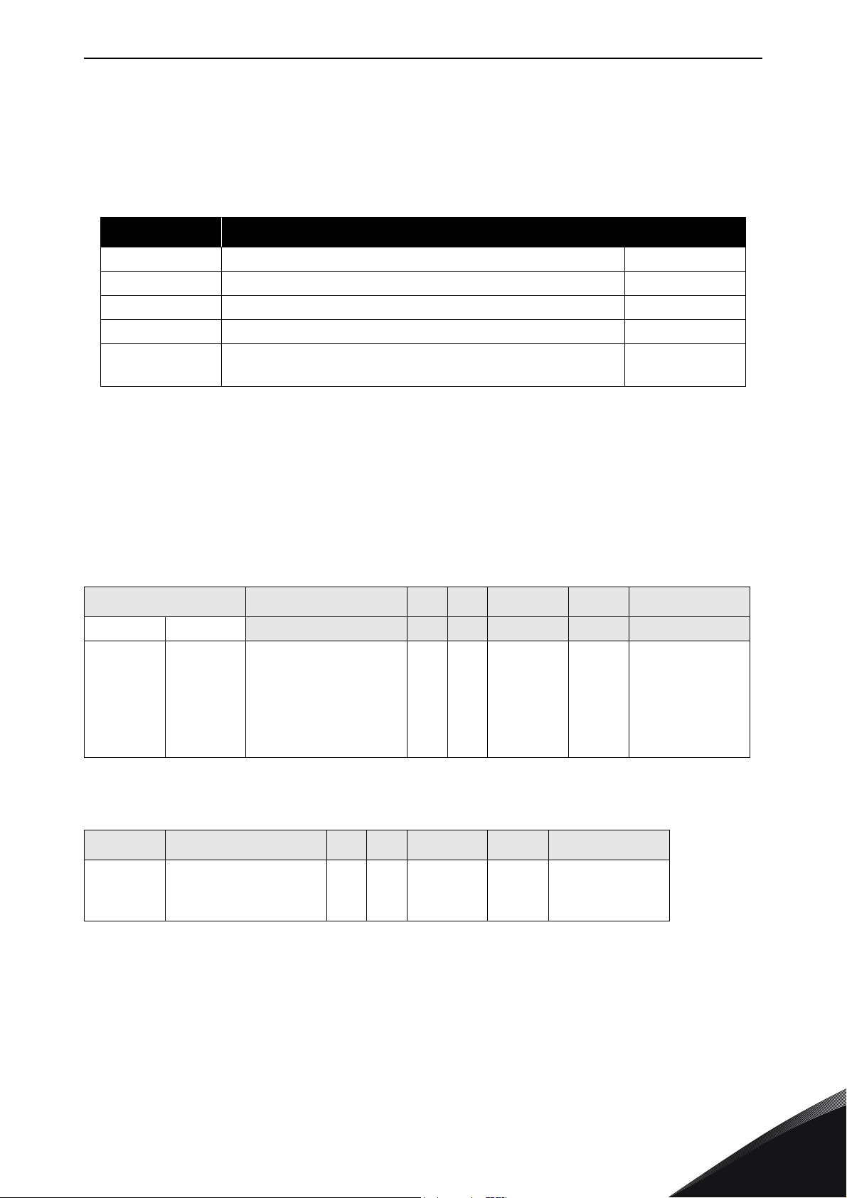
Here you can see a general overview of the behaviour associated with an Explicit Messaging
Connection Object (Instance type attribute = Explicit Messaging).
Delete
Child instance
Deleted or
Transitions to Timed
Out and no other
child instances are in
the Established
state
Open Explicit Messaging
Connection Response
Transmitted by a server end-point
Open Explicit Messaging Connection Response
Received by a client end-point
Inactivity/Watchdog Timeout &
Watchdog_timeout_action=
Deferred Delete and at least one child
instance is in the Established state.
Non-existent
Delete
Inactivity/Watchdog Timeout &
Watchdog_timeout_action=
Auto Delete or this attribute is
set to Deferred Delete and no
child instances are in the
Established state.
Get_Attribute/
Deferred Delete Established
Receive Data/Reset
Set_Attribute/
Reset
7083_UK
Figure 13. Explicit Messaging Connection Object State Transition Diagram
Explicit Connection Expected Packet Rate (EPR) is set by default to 2500, meaning that watchdog
timeout action will occur after 10s.
7
Tel. +358 (0) 201 2121 • Fax +358 (0)201 212 205
Page 55
Fault handling vacon • 52
8. FAULT HANDLING
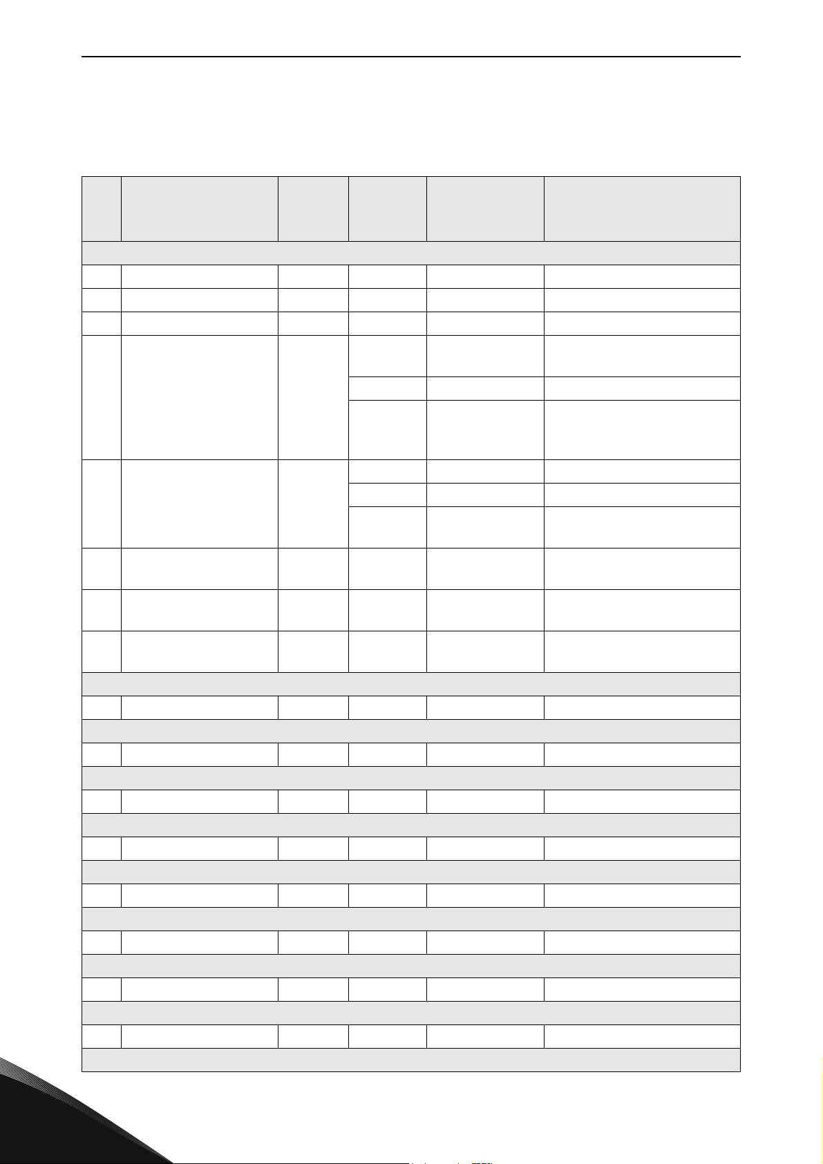
The following chapter describes different fault activation situations in OPTE7.
Table 40. Fault Activation Sources
Name Description N LED
BUS-OFF CAN driver in in bus-off state Red
DUP_MAC-ID Duplicate MAC ID is found during startup/ MAC ID change Red
PASSIVE CAN driver is in passive state -
EXT_PWR External +24V is not detected Off
PIO_TO
• Bus-off and passive states are cleared when CAN driver goes to active state.
• External power fault is cleared when +24V is connected to option board connector.
• Duplicate MAC check is made every time the MAC-ID is changed or the option board is
powered up. The fault is cleared, when the duplicate MAC-ID check passes.
• Polled I/O connection timeout is cleared when the I/O connection is released or allocated
Polled I/O connection Expected Packet Rate watchdog
timeout
Flashing red
How the AC drive will react to these fault situations can be defined in application:
Table 41. Fieldbus Fault Reaction in Vacon
Code Parameter Min Max Default ID Description
Vacon 100 Vacon 20
P3.9.1.6 P13.19
Table 42. Fieldbus Fault Reaction in Vacon
Code Parameter Min Max Default ID Description
P9.15
Response to fieldbus
Response to fieldbus
fault
fault
0 2 2 733
® 100 and Vacon® 20 (standard application)
0 4 3 733
® 20X (standard application)
0 = No action
1 = Warning
2 = Fault
0 = No response
1 = Alarm
2 = Fault, stop
by stop function
3 = Fault, stop
by coasting
24-hour support +358 (0)201 212 575 • Email: [email protected]
8
Page 56

vacon • 53 Fault handling
8.1 General and additional error codes
Table 43. General Error Codes
Code General Error Description
0x00 Success
0x02 Resource Unavailable
0x08 Service Not Supported
0x09 Invalid Attribute Value Invalid attribute data detected.
0x0B Already In Requested State Requested release connection does not exist.
0x0C Object State Conflict
0x0E Attribute Not Settable
0x10 Device State Conflict
0x13 Not Enough Data Explicit request was too short.
0x14 Attribute Not Supported
0x15 Too Much Data The service supplied more data than was expected.
0x16 Object Does Not Exist The object specified does not exist in the device.
Service was successfully performed by the object
specified.
Resources needed for the object to perform the
requested service were unavailable.
The requested service was not implemented or was
not defined.
The object cannot perform the requested service in
its current mode/state.
Already allocated to another master.
A request to modify a non-modifiable attribute was
received.
The current mode/state of the device prohibits the
execution of the requested service.
The attribute specified in the request is not supported.
0x20 Invalid Parameter
0x28 Invalid Member ID
Table 44. Additional Error Codes
Code Description
0x01 Predefined Master/Slave Connection Set allocation conflict
0x02 Invalid Allocation/Release Choice parameter
0x03
0x04
Message received on Group 2 Only Unconnected Explicit Request
message port that was not an Allocate or Release message
Resource required for use with the Predefined Master/Slave Connection Set is not available
Message received on Group 2 unconnected
requested port was not an allocate or release message.
A parameter associated with the request was
invalid.
The Member ID specified in the request does not
exist.
8
Tel. +358 (0) 201 2121 • Fax +358 (0)201 212 205
Page 57

Appendix A: Object dictionary vacon • 54
9. APPENDIX A: OBJECT DICTIONARY
9.1 Implemented CIP objects
9.1.1 List of Object Classes
The Communication Interface supports the following object classes.
Table 45. Implemented Object Classes
Class Object
0x01 Identity
0x02 Message Router
Required by DeviceNet
Required by Drive
Profile
0x03 DeviceNet
0x04 Assembly
0x05 DeviceNet Connection
0x28 Motor Data
0x29 Control Supervisor
0x2A AC/DC Drive
Vendor-Specific 0xA0 Vendor Parameter
24-hour support +358 (0)201 212 575 • Email: [email protected]
9
Page 58

vacon • 55 Appendix A: Object dictionary
Vendor
Parameter
Drive
AC/DC
Control
Supervisor
Data
Class Inst. Class Inst. Class Inst. Class Inst.
ed)
Inst.
(Poll
Connection Motor
Message
cit)
Inst.
(Expli
Y
Y
DeviceNet Assembly
Router
Class Inst Class Inst Class Inst Class Inst. Class
9
9.1.2 List of Services
The following table shows the services supported by these object classes.
Service Name Identity
Service
Code (in
hex)
0x4B
Slave_Connection_Set
Release_Master/
Slave_Connection_Set
* ) Supports reset type 0 and 1
0x4C
Tel. +358 (0) 201 2121 • Fax +358 (0)201 212 205
Allocate_Master/
0x05 Reset Y* Y Y
0x09 Delete Y Y
0x10 Set_Attribute_Single Y Y Y Y Y Y Y Y Y Y
0x0E Get_Attribute_Single Y Y Y Y Y Y Y Y Y Y Y Y Y Y Y Y Y Y Y
Page 59

Appendix A: Object dictionary vacon • 56
9.1.3 Class Code 0x01 - Identity Object
Table 46.
Default
# Attribute Name Services
1 Revision Get 1 UINT Revision of this object
2 Max Instance Get 1 UINT Maximum instance number
3 Number of Instances Get 1 UINT Number of object instances
4 Optional Attribute List Get
5 Optional Service List Get
Minimum
Maximum
Instance 0
8 UINT Number of attributes
{1, 2, 3, 4,
5, 6, 7,
176}
2 UINT Number of services
{5, 14} ARRAY of UINT
Data Type Description
STRUCT of:
ARRAY of UINT
STRUCT of: List of optional services
List of optional instance
attributes
List of optional attribute
numbers
List of optional service
codes
Max Class Attribute
6
7
176 Object Name Get “Identity” SHORT_STRING
1 Vendor ID Get 443 UINT
2 Device Type Get 2 UINT
3 Product Code Get 2 UINT
4 Revision Get N/A
ID
Max Instance
Attribute ID
Get 176 UINT
Get 10 UINT
Instance 1
STRUCT of:
USINT Major revision
USINT Minor revision
The attribute ID number of
the last class attribute
The attribute ID number of
the last instance attribute
ASCII Name for the Object
Class
Identification of each vendor by number.
443 = Vacon Plc
Indication of the general
type of product.
2 = AC Drive
Identification of a particular product of an individual
vendor.
2 = OPTE7
Revision of the item the
Identity Object represents
24-hour support +358 (0)201 212 575 • Email: [email protected]
9
Page 60

vacon • 57 Appendix A: Object dictionary
Table 46.
Default
# Attribute Name Services
5Status Get
6 Serial Number Get N/A UDINT
7 Product Name Get “OPTE7” SHORT_STRING
8 State Get
Minimum
Maximum
N/A
0
65535
N/A
0
5
Data Type Description
Summary status of the
device. Defined in ODVA
DeviceNet specification.
Supported bits:
Bit 0 = Owned
Bit 7 = System fault
WORD
USINT
Bit 8 = Minor Recoverable
Fault
Bit 9 = Minor Unrecoverable
Fault
Bit 10 = Major Recoverable
Fault
Bit 11 = Major Unrecoverable Fault
Serial number of the device.
YYMMDDxxxx, where
YY = year of manufacture
MM = month of manufacture
DD = day of manufacture
xxxx = running number
Human readable identification
Present state of the device
as represented by the state
transition diagram.
0 = Nonexistent
1 = Device Self-Testing
2 = Standby
3 = Operational
4 = Major Recoverable Fault
5 = Major Unrecoverable
Fault
9
9
10 Heartbeat Interval
Configuration
Consistency Value
Get
Get
Set
N/A
0
65535
0
0
255
UINT
USINT
Tel. +358 (0) 201 2121 • Fax +358 (0)201 212 205
Contents identify configuration of the device
Heartbeat message send
interval in seconds. By
default disabled. Zero disables the transmission.
Page 61

Appendix A: Object dictionary vacon • 58
9.1.4 Class Code 0x02 - Message Router Object
Table 47.
Default
# Attribute Name Services
1 Revision Get 1 UINT Revision of this object
2 Max Instance Get 1 UINT Maximum instance number
3 Number of Instances Get 1 UINT Number of object instances
4 Optional Attribute List Get
5 Optional Service List Get
Minimum
Maximum
Instance 0
8 UINT Number of attributes
{1, 2, 3, 4,
5, 6, 7,
176}
1 UINT Number of services
{14} ARRAY of UINT
Data Type Description
STRUCT of:
ARRAY of UINT
STRUCT of: List of optional services
List of optional instance
attributes
List of optional attribute
numbers
List of optional service
codes
Max Class Attribute
6
7
176 Object Name Get
1 Object List Get N/A
9.1.5 Class Code 0x03 - DeviceNet Object
# Attribute Name Services
ID
Max Instance
Attribute ID
Get 176 UINT
Get 1 UINT
“Message
Router”
Instance 1
Table 48.
Default
Minimum
Maximum
SHORT_STRING
ARRAY of UINT Classes
The attribute ID number of
the last class attribute
The attribute ID number of
the last instance attribute
ASCII Name for the Object
Class
Structure with an array of
STRUCT of:
UINT Number of classes
Data Type Description
object class codes supported by the device
Instance 0
1 Revision Get 2 UINT Revision of this object
2 Max Instance Get 1 UINT Maximum instance number
24-hour support +358 (0)201 212 575 • Email: [email protected]
9
Page 62

vacon • 59 Appendix A: Object dictionary
Table 48.
Default
# Attribute Name Services
3 Number of Instances Get 1 UINT Number of object instances
4 Optional Attribute List Get
5 Optional Service List Get
Minimum
Maximum
8 UINT Number of attributes
{1, 2, 3, 4,
5, 6, 7,
176}
1 UINT Number of services
{14} ARRAY of UINT
Data Type Description
STRUCT of:
ARRAY of UINT
STRUCT of: List of optional services
List of optional instance
attributes
List of optional attribute
numbers
List of optional service
codes
Max Class Attribute
6
7
176 Object Name Get
1MAC ID
2Baud Rate
3
ID
Max Instance
Attribute ID
BOI (Bus-off
Interrupt)
Get 176 UINT
Get 10 UINT
Get
Set
Get
Set
Get
Set
“Device-
Net”
Instance 1
63
0
63
0
0
2
1
0
1
The attribute ID number of
the last class attribute
The attribute ID number of
the last instance attribute
SHORT_STRING
USINT Node address
USINT
BOOL
ASCII Name for the Object
Class
The baud rate of the device
0 = 125 kBaud
1 = 250 kBaud
2 = 500 kBaud
If value is changed via network, it will be taken into
use only after a reset /
power cycle. If changed via
panel, baud rate will be
taken into use immediately.
0 = Hold the CAN chip in
bus-off state upon detection
of a bus-off indication
1 = If possible, fully reset
the CAN chip and continue
communication upon detection of a bus-off indication
9
4Bus-off counter
Get
Set
0
0
255
Number of times CAN went
USINT
Tel. +358 (0) 201 2121 • Fax +358 (0)201 212 205
to bus-off state. Received
data is not used. Counter
always reset to 0.
Page 63

Appendix A: Object dictionary vacon • 60
Table 48.
Default
# Attribute Name Services
Minimum
Maximum
Data Type Description
STRUCT of:
5
100 Bus-off Separation Get 128 USINT
Allocation
Information
Get N/A
BYTE
USINT
Allocation Choice Master’s
Mac ID
Allocation Choice Byte
Bit 0 = Explicit messaging
Bit 1 = Polled I/O
Master’s MAC ID
0-63 = valid
255 = unallocated
Messages that have to be
received by the device to
leave bus-off state. This
value is set by the CAN controller.
24-hour support +358 (0)201 212 575 • Email: [email protected]
9
Page 64
vacon • 61 Appendix A: Object dictionary
9.1.6 Class Code 0x04 - Assembly Object
Table 49.
Default
# Attribute Name Services
1 Revision Get 2 UINT Revision of this object
2 Max Instance Get 117 UINT Maximum instance number
3 Number of Instances Get 12 UINT Number of object instances
4 Optional Attribute List Get
5 Optional Service List Get
Minimum
Maximum
Instance 0
8 UINT Number of attributes
{1, 2, 3, 4,
5, 6, 7,
176}
1 UINT Number of services
{14} ARRAY of UINT
Data Type Description
STRUCT of:
ARRAY of UINT
STRUCT of: List of optional services
List of optional instance
attributes
List of optional attribute
numbers
List of optional service
codes
Max Class Attribute
6
7
176 Object Name Get
3 Data Get N/A ARRAY See Chapter 7.1.2.1.
3 Data Get N/A ARRAY See Chapter 7.1.2.2.
3 Data Get N/A ARRAY See Chapter 7.1.2.3.
3 Data Get N/A ARRAY See Chapter 7.1.2.4.
3 Data Get N/A ARRAY See Chapter 7.1.2.1.
3 Data Get N/A ARRAY See Chapter 7.1.2.2.
3 Data Get N/A ARRAY See Chapter 7.1.2.3.
ID
Max Instance
Attribute ID
Get 176 UINT
Get 3 UINT
“Assem -
bly”
Instance 20
Instance 21
Instance 23
Instance 25
Instance 70
Instance 71
Instance 73
SHORT_STRING
The attribute ID number of
the last class attribute
The attribute ID number of
the last instance attribute
ASCII Name for the Object
Class
9
Instance 75
3 Data Get N/A ARRAY See Chapter 7.1.2.4.
Instance 101
Tel. +358 (0) 201 2121 • Fax +358 (0)201 212 205
Page 65
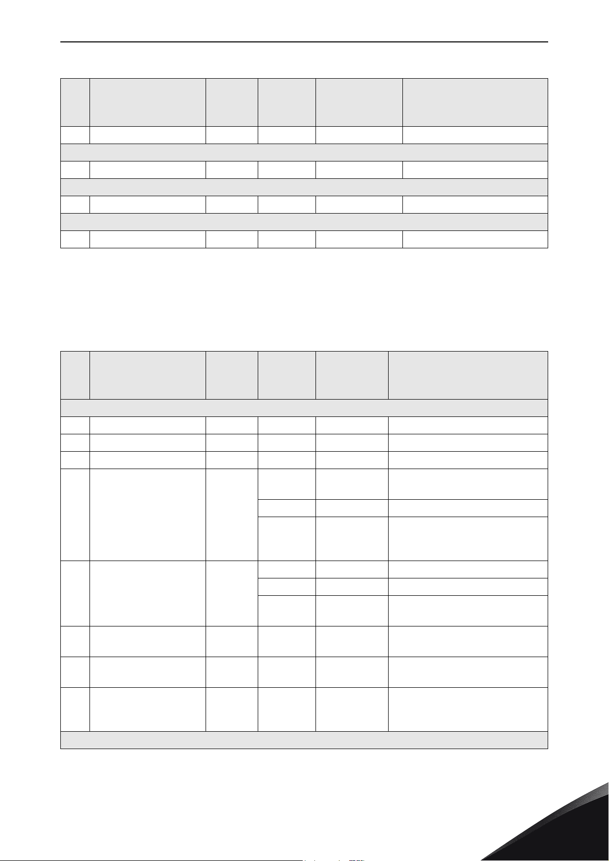
Appendix A: Object dictionary vacon • 62
Table 49.
Default
# Attribute Name Services
3 Data Get N/A ARRAY See Chapter 7.1.2.5.
3 Data Get N/A ARRAY See Chapter 7.1.2.6.
3 Data Get N/A ARRAY See Chapter 7.1.2.5.
3 Data Get N/A ARRAY See Chapter 7.1.2.6.
9.1.7 Class Code 0x05 - DeviceNet Connection Object
Minimum
Maximum
Instance 111
Instance 107
Instance 117
Data Type Description
Table 50.
Default
# Attribute Name Services
1 Revision Get 1 UINT Revision of this object
2 Max Instance Get 2 UINT Maximum instance number
3 Number of Instances Get 2 UINT Number of object instances
4 Optional Attribute List Get
5 Optional Service List Get
Max Class Attribute
6
7
176 Object Name Get
ID
Max Instance
Attribute ID
Get 176 UINT
Get 17 UINT
Minimum
Maximum
Instance 0
8 UINT Number of attributes
{1, 2, 3, 4,
5, 6, 7,
176}
1 UINT Number of services
{14}
“Device-
Net Con-
nection”
Data Type Description
STRUCT of:
ARRAY of
UINT
STRUCT of: List of optional services
ARRAY of
UINT
SHORT_STRINGASCII Name for the Object
List of optional instance
attributes
List of optional attribute
numbers
List of optional service codes
The attribute ID number of the
last class attribute
The attribute ID number of the
last instance attribute
Class
Instance 1 - Explicit Connection
24-hour support +358 (0)201 212 575 • Email: [email protected]
9
Page 66

vacon • 63 Appendix A: Object dictionary
Table 50.
Default
# Attribute Name Services
1 State Get
2 Instance Type Get 0 USINT
3
4
Transport Class
Trigger
Produced Connection
ID
Get 0x83 BYTE
Get
Minimum
Maximum
0
0
5
0x5FA
0x403
0x5FA
Data Type Description
State of the object
0 = Non-existent
1 = Configuring
USINT
UINT
2 = Waiting
3 = Established
4 = Timeout
5 = Deferred Delete
Indicates either I/O or
Messaging Connection.
0 = Explicit Messaging
1 = I/O
Defines behavior of the
connection. Defines behavior
of the Connection. See CIP
Vol.1 chapter 3.4.4.3 for more
details.
Placed in CAN Identifier Field
when the Connection
transmits on a DeviceNet
subnet. See Table 55.
5
6
7
8
9Expected Packet Rate
12
Consumed
Connection ID
Initial Comm.
Characteristics
Produced Connection
Size
Consumed
Connection Size
Watchdog Timeout
Action
Get N/A UINT
Get 0x21 BYTE
Get 99 UINT
Get 99 UINT
Get
Set
Get
Set
2500
0
65535
1
1
3
UINT
USINT
CAN Identifier Field value that
denotes message to be
received on a DeviceNet
subnet. See Table 55.
Defines the Message Group(s)
across which productions and
consumptions associated with
this connection occur. See CIP
Vol.3 chapter 3-2.4 for more
details.
Maximum number of bytes
transmitted across this
Connection
Maximum number of bytes
received across this
Connection
Defines timing associated with
this connection
Defines how to handle
Inactivity/Watchdog timeouts.
1 = Auto Delete
2 = Invalid for Explicit
Connection
3 = Deferred Delete
9
Produced Connection
13
Length
Get 0 UINT
Tel. +358 (0) 201 2121 • Fax +358 (0)201 212 205
Not used in Explicit
Connection
Page 67

Appendix A: Object dictionary vacon • 64
Table 50.
Default
# Attribute Name Services
Minimum
Maximum
Data Type Description
Produced Connection
14
15
16
17
1 State Get
2 Instance Type Get 1 USINT
3
4
5
6
Production Inhibit
Produced Connection
Path
Consumed
Connection Path
Length
Consumed
Connection Path
Time
Transport Class
Trigger
ID
Consumed
Connection ID
Initial Comm.
Characteristics
Get {0}
Get 0 UINT
Get {0}
Get 0 UINT
Instance 2 - Polled I/O Connection
0
0
4
Get 131 BYTE
0x3FF
Get
Get N/A UINT
Get 1 BYTE
0x3C1
0x3FF
ARRAY of
USINT
ARRAY of
USINT
USINT
UINT
Not used in Explicit
Connection
Not used in Explicit
Connection
Not used in Explicit
Connection
Not used in Explicit
Connection
State of the object
0 = Non-existent
1 = Configuring
2 = Waiting
3 = Established
4 = Timeout
Indicates either I/O or
Messaging Connection.
0 = Explicit Messaging
1 = I/O
Defines behavior of the
connection. See CIP Vol.1
chapter 3.4.4.3 for more
details.
Placed in CAN Identifier Field
when the Connection
transmits on a DeviceNet
subnet. See Table 55.
CAN Identifier Field value that
denotes message to be
received on a DeviceNet
subnet. See Table 55.
Defines the Message Group(s)
across which productions and
consumptions associated with
this connection occur. See CIP
Vol.3 chapter 3-2.4 for more
details.
Produced Connection
7
8
24-hour support +358 (0)201 212 575 • Email: [email protected]
Size
Consumed
Connection Size
Get 99 UINT
Get 99 UINT
Maximum number of bytes
transmitted across this
Connection
Maximum number of bytes
received across this
Connection
9
Page 68

vacon • 65 Appendix A: Object dictionary
Table 50.
Default
# Attribute Name Services
Minimum
Maximum
Data Type Description
9 Expected Packet rate
12
13
14
15
16
Watchdog Timeout
Action
Produced Connection
Length
Produced Connection
Path
Consumed
Connection Path
Length
Consumed
Connection Path
Get
Set
Get
Set
Get 6 UINT
Get
Set
Get 6 UINT
Get
Set
0
0
65535
0
0
0
N/A
N/A
UINT
USINT
ARRAY of
USINT
ARRAY of
USINT
Defines timing associated with
this connection
Defines how to handle
Inactivity/Watchdog timeouts.
0 = Transition to Timed Out
1 = Invalid for I/O Connection
Number of bytes in the
Produced Connection Path
attribute
Application obj. producing data
on this connection. See
Chapter 10.2 for more details.
Number of bytes in the
Consumed Connection Path
attribute
Specifies the application
object(s) that are to receive the
data consumed by this
connection. See Chapter 10.2
for more details.
17
9.1.8 Class Code 0x28 - Motor Data Object
# Attribute Name Services
1 Revision Get 1 UINT Revision of this object
2 Max Instance Get 1 UINT Maximum instance number
3 Number of Instances Get 1 UINT Number of object instances
4 Optional Attribute List Get
Production Inhibit
Time
Get 0 UINT
Table 51.
Default
Minimum
Maximum
Instance 0
8 UINT Number of attributes
{1, 2, 3, 4,
5, 6, 7,
176}
Data Type Description
STRUCT of:
ARRAY of UINT
Not used in Polled I/O
Connection
List of optional instance
attributes
List of optional attribute
numbers
9
Tel. +358 (0) 201 2121 • Fax +358 (0)201 212 205
Page 69

Appendix A: Object dictionary vacon • 66
Table 51.
Default
# Attribute Name Services
5 Optional Service List Get
Max Class Attribute
6
7
176 Object Name Get
ID
Max Instance
Attribute ID
Get 176 UINT
Get 15 UINT
Minimum
Maximum
1 UINT Number of services
{14} ARRAY of UINT
“Motor
Data”
Instance 1
Data Type Description
STRUCT of: List of optional services
List of optional service
codes
The attribute ID number of
the last class attribute
The attribute ID number of
the last instance attribute
SHORT_STRING
ASCII Name for the Object
Class
3 Motor Type
6 Rated Current
7Rated Voltage
9 Rated Frequency
12 Pole Count Get N/A UINT
15 Base Speed
Get
Set
Get
Set
Get
Set
Get
Set
Get
Set
7
3
7
N/A UINT
N/A UINT
N/A UINT
N/A UINT
USINT
Motor types supported:
3 = PM Synchronous Motor
7 = Squirrel Cage Induction
Motor
Motor nominal current
Unit: 100 mA
Motor nominal voltage
Unit: Volts
Motor nominal frequency
Unit: Hz
Number of poles in the
motor
Nominal speed at rated frequency. Unit: RPM
24-hour support +358 (0)201 212 575 • Email: [email protected]
9
Page 70

vacon • 67 Appendix A: Object dictionary
9.1.9 Class Code 0x29 - Control Supervisor Object
Table 52.
Default
# Attribute Name Services
1 Revision Get 1 UINT Revision of this object
2 Max Instance Get 1 UINT Maximum instance number
3 Number of Instances Get 1 UINT Number of object instances
4 Optional Attribute List Get
5 Optional Service List Get
Minimum
Maximum
Instance 0
8 UINT Number of attributes
{1, 2, 3, 4,
5, 6, 7,
176}
1 UINT Number of services
{14}
Data Type Description
STRUCT of:
ARRAY of
UINT
STRUCT of: List of optional services
ARRAY of
UINT
List of optional instance attributes
List of optional attribute numbers
List of optional service codes
Max Class Attribute
6
7
176 Object Name Get
3Run1
4Run2
ID
Max Instance
Attribute ID
Get 176 UINT
Get 15 UINT
Get
Set
Get
Set
The attribute ID number of the
last class attribute
The attribute ID number of the
last instance attribute
“Control
Supervi-
sor”
Instance 1
0
0
1
N/A BOOL See Table 39.
SHORT_STRINGASCII Name for the Object
Class
BOOL See Table 39.
9
Tel. +358 (0) 201 2121 • Fax +358 (0)201 212 205
Page 71

Appendix A: Object dictionary vacon • 68
Table 52.
Default
# Attribute Name Services
5NetCtrl
6 State Get
Get
Set
Minimum
Maximum
0
0
1
0
0
7
Data Type Description
Requests Run/Stop control to
be local or from network.
0 = Local Control
1 = Network Control
Note that this selection does
not force control place to network if set. This bit only
BOOL
USINT
enables commands to be sent
to the drive. Depending on how
it is parametrised, this command might be ignored or
used. See Chapter 6.4 for more
details.
Actual status of control is
reflected in attribute 15.
State of Control Supervisor
Instance. See Chapter 7.1.3.
0 = Vendor-Specific
1 = Startup
2 = Not_Ready
3 = Ready
4 = Enabled
5 = Stopping
6 = Fault_Stop
7 = Faulted
N/A
7 Running1 Get
N/A
8 Running2 Get
N/A
9Ready Get
N/A
10 Faulted Get
11 Warning Get
12 FaultRst
Get
Set
N/A
Running forward status
0
1
0
1
0
1
0
1
0
0
0
1
BOOL
BOOL
BOOL
BOOL
BOOL
BOOL
0 = Other state
1 = Running forward
Running reverse status
0 = Other state
1 = Running reverse
Ready to accept a run event
0 = Other state
1 = Ready to accept a run event
Fault occurred
0 = No faults present
1 = Fault occurred (latched)
Warning present
0 = No warnings present
1 = Warning present (not
latched)
Fault reset request
0 = No action
0 -> 1 = Fault reset request
1 = No action
24-hour support +358 (0)201 212 575 • Email: [email protected]
9
Page 72

vacon • 69 Appendix A: Object dictionary
Table 52.
Default
# Attribute Name Services
13 FaultCode Get N/A UINT
14 WarnCode Get N/A UINT
15 CtrlFromNet Get
Minimum
Maximum
N/A
0
1
Data Type Description
If in Faulted state, the Fault-
Code indicates the fault that
caused the transition to
Faulted state. If not in Faulted
state, the FaultCode indicates
the fault that caused the last
transition to the Faulted state.
The supported fault codes are
listed in Chapter 11.
Indicates the lowest valued
warning that caused the Warn-
ing bit to be TRUE.
Status of the Run/Stop control
source
BOOL
0 = Control is local (as
parametrised)
1 = Control is from network
9
Tel. +358 (0) 201 2121 • Fax +358 (0)201 212 205
Page 73

Appendix A: Object dictionary vacon • 70
9.1.10 Class Code 0x2A - AC/DC Drive Object
Table 53.
Default
# Attribute Name Services
1 Revision Get 1 UINT Revision of this object
2 Max Instance Get 1 UINT Maximum instance number
3 Number of Instances Get 1 UINT Number of object instances
4 Optional Attribute List Get
5 Optional Service List Get
Minimum
Maximum
Instance 0
8 UINT Number of attributes
{1, 2, 3, 4,
5, 6, 7,
176}
1 UINT Number of services
{14}
Data Type Description
STRUCT of:
ARRAY of
UINT
STRUCT of: List of optional services
ARRAY of
UINT
List of optional instance attri-
butes
List of optional attribute num-
bers
List of optional service codes
Max Class Attribute
6
7
176 Object Name Get
3At Reference Get
ID
Max Instance
Attribute ID
Get 176 UINT
Get 29 UINT
“AC/D C
Drive”
Instance 1
N/A
0
1
The attribute ID number of the
last class attribute
The attribute ID number of the
last instance attribute
SHORT_STRINGASCII Name for the Object
Class
1 = Drive actual at reference
BOOL
(speed or torque reference)
based on mode
24-hour support +358 (0)201 212 575 • Email: [email protected]
9
Page 74

vacon • 71 Appendix A: Object dictionary
Table 53.
Default
# Attribute Name Services
4Net Ref
5 Net Proc
Get
Set
Get
Set
Minimum
Maximum
0
0
1
0
0
1
Data Type Description
Requests torque or speed
reference to be local or from
the network.
0 = Set Reference not DN
Control
1 = Set Reference at DN
Control
This selection does not force
BOOL
BOOL
the drive to use network
reference. When set, the
reference values are sent to
the drive, but depending on
how it is parametrised, it
might ignore this reference
value. See Chapter 6.4 for
more details.
Actual status of reference is
reflected in attribute 29.
Requests process control ref-
erence to be active. See
Chapter 7.1.2.4 for more
details.
6Drive Mode
7 Speed Actual Get
8 Speed Ref
9 Current Actual Get
10 Current Limit
11 Torque Actual Get
12 Torque Ref
Get
Set
Get
Set
Get
Set
Get
Set
N/A
0
3
N/A
0
32767
N/A
0
32767
N/A
0
32767
N/A
0
32767
N/A
-32768
32767
N/A
-32768
32767
USINT
INT
INT
INT
INT
INT
INT
0 = Open loop frequency
1 = Open loop speed
2 = Closed loop speed
3 = Torque control
Actual drive speed
Unit: RPM
Speed reference
Unit: RPM
Actual motor phase current
Unit: 100 mA
Motor phase current limit
Unit: 100 mA
Actual torque
Unit: Nm / 2
where TorqueScale is attribute
24
Torque reference
Unit: Nm / 2
where TorqueScale is attribute
24
Tor queSca le
Tor queSca le
,
,
9
Tel. +358 (0) 201 2121 • Fax +358 (0)201 212 205
Page 75

Appendix A: Object dictionary vacon • 72
Table 53.
Default
# Attribute Name Services
13 Process Actual Get N/A INT
14 Process Ref
15 Power Actual Get N/A INT
16 Input Voltage Get N/A INT
17 Output Voltage Get N/A INT
18 Accel Time
19 Decel Time
20 Low Spd Limit
21 High Spd Limit
24 Torque Scale
29 Ref From Net Get
Get
Set
Get
Set
Get
Set
Get
Set
Get
Set
Get
Set
Minimum
Maximum
N/A INT
N/A UINT
N/A UINT
N/A UINT
N/A UINT
0
-8
7
N/A
0
1
Data Type Description
Actual process control value.
Mapped to FB
ProcessDataOut1.
Process control reference. See
Chapter 7.1.2.4 for detailed
information.
Actual output power
Unit: Watts
Input Voltage
Unit: Volts
Output Voltage
Unit: Volts
Acceleration time
Unit: ms
Deceleration time
Unit: ms
Minimum speed limit
Unit: RPM
Maximum speed limit
Unit: RPM
Torque scaling factor. Scaling
SINT
BOOL
is accomplished as follows:
ScaledTorque = Nm /
Torq ue Sca le
2
Status of torque/speed refer-
ence.
0 = Local torque/speed reference
1 = Network torque/speed reference
9.1.11 Class Code 0xA0 - Vendor Parameter Object
Table 54.
Default
# Attribute Name Services
NOT SINGLE ATTRIBUTE PROVIDED
24-hour support +358 (0)201 212 575 • Email: [email protected]
Minimum
Maximum
Data Type Description
9
Page 76

vacon • 73 Appendix A: Object dictionary
The Vendor Parameter Object is used to read and write parameters with an ID number directly from
control unit. The desired Instance number and attribute number is constructed in the following way:
• Instance = Parameter ID (High Byte) + 1
• Attribute = Parameter ID (Low Byte)
Examples:
1) Energy Counter, ID = 2291 = 0x08F3
a) Instance ID = 0x08 + 1 = 0x09
b) Attribute ID = 0xF3
2) Maximum Frequency, ID = 102 = 0x0066
a) Instance ID = 0x00 + 1 = 0x01
b) Attribute ID = 0x66
NOTE! All the values (when applicable) are truncated to 16-bit values and the scale varies between
different types of values.
9
Tel. +358 (0) 201 2121 • Fax +358 (0)201 212 205
Page 77

Appendix B: Communication attribute details vacon • 74
10. APPENDIX B: COMMUNICATION ATTRIBUTE DETAILS
This appendix can be used to determine how some of the DeviceNet communication class attributes
are defined. For more details, refer to Vol.1 and Vol.3 of CIP.
10.1 DeviceNet’s use of the CAN Identifier Field
The CAN Identifier bits that are available on DeviceNet are divided into message groups. The
predefined Master/Slave connections that are relevant to DeviceNet can be seen in the table below.
The full list of messages can be seen from CIP Vol.3 in Chapter 3-7.
Table 55. Predefined Master/Slave Connection Set Identifier Fields
Identifier Bits Identity Usage
109876543210
0
0 1 1 1 1 Source MAC ID
1 0MAC ID
1 0 Source MAC ID 0 1 1
1 0 Destination MAC ID 1 0 0
1 0 Destination MAC ID 1 0 1
1 0 Destination MAC ID 1 1 1
Group 1
Message ID
Source MAC ID Group 1 Messages 000-3FF
Group 2
Message ID
Hex
Range
Slave’s I/O Poll
Response
Group 2 Messages 400-5FF
Slave’s Explicit
Response Message
Master’s Explicit
Request Message
Master’s I/O Poll
Command
Duplicate MAC ID
Check Message
10.2 Connection object paths
This chapter describes how the connection object path is encoded to select different assembly
instances in assembly object for I/O communication. For more detailed information, refer to Vol.1 of
CIP Appendix C: C-1 Abstract Syntax Encoding Coding for Segment Types.
The following figures show how the Produced Connection Path (class code 5, instance 2, attribute
14) and the Consumed Connection Path (class code 5, instance 2, attribute 16) are used to map
instances to assembly object class. For more information refer to Chapter 9.1.7.
24-hour support +358 (0)201 212 575 • Email: [email protected]
10
Page 78

vacon • 75 Appendix B: Communication attribute
7084_UK
Connection Object Class (ID 5)
Connection Instance ID 2
Assembly Instance ID 21
Assembly Instance ID 71
Assembly Object Class (ID 4)
Class ID 4,
Instance ID 21,
Attribute ID 3
Class ID 4,
Instance ID 71,
Attribute ID 3
Produced
connection
path length
0x06
0x06
Num Members
Member List
Data
(Attribute ID3)
Num Members
Member List
Data
(Attribute ID3)
0x20 0x04
0x24 0x15
0x30 0x03
0x20 0x04
0x24 0x47
0x30 0x03
Consumed
connection
path length
Consumed
connection
path
Produced
connection
path
Segment Type = Logical Segment
Segment Format: Logical Type=Class
Format = 8 bits
0x20 0x04 0x24 0x15 0x30 0x03
Class 4
Figure 14. Example Encoding for Connection Object Paths
Segment Type = Logical Segment
Segment Format: Logical Type=Instance
Logical Format = 8 bits
Segment Type = Logical Segment
Segment Format: Logical Type=Attribute ID
Logical Format = 8 bits
Instance 21
Attribute ID 3
7085_UK
10
Figure 15. Path with 8-bit class
Tel. +358 (0) 201 2121 • Fax +358 (0)201 212 205
Page 79

Appendix C: Fault and warning codes vacon • 76
11. APPENDIX C: FAULT AND WARNING CODES
OPTE7 uses the implied fault/warning codes for the device profile. For AC drives, the implied fault/
warning codes used are DRIVECOM Nutzergruppe e.V 16-bit codes. The supported fault codes are
listed in the table below. The full list of error codes can be found in Vol. 1 of CIP, section 5-29.6.
Table 56.
Code Value
[Hex]
0000 No fault
1000 General Fault
2300 Current, Device Output Side
2330 Short to Earth
3130 Phase Failure
3210 Overvoltage inside the device
3220 Undervoltage inside the device
4210 Excess Device Temperature
4220 Inadequate Device Temperature
5120 DC Link Power Supply
5200 Control
5420 Chopper
6010 Software Reset (Watchdog)
6100 Internal Software
7111 Brake Chopper Failure
7120 Motor
7500 Communication
Meaning
7600 Data Memory
9000 External Malfunction
24-hour support +358 (0)201 212 575 • Email: [email protected]
11
Page 80

Find your nearest Vacon office
on the Internet at:
www.vacon.com
Manual authoring:
[email protected]
Vacon Plc.
Runsorintie 7
65380 Vaasa
Finland
Subject to change without prior notice
© 2015 Vacon Plc.
Document ID:
Rev. B
Sales code: DOC-OPTE7+DLUK
 Loading...