

Page 1

vacon
ac drives
®
optec
ethercat option board
installation manual
Page 2

Page 3

vacon • 3
TABLE OF CONTENTS
Document: DPD01207D
Release date: 27/5/20
1. Safety...............................................................................................................6
1.1 Danger................................................................................................................................6
1.2 Warnings ............................................................................................................................7
1.3 grounding and earth fault protection ................................................................................8
2. OPTEC EtherCAT - General ..............................................................................9
2.1 New features ....................................................................................................................11
3. EtherCAT option board technical data............................................................12
3.1 General.............................................................................................................................12
3.2 Cables...............................................................................................................................12
4. Layout and connections..................................................................................13
4.1 Layout and connections ...................................................................................................13
4.2 LED Indications ................................................................................................................14
4.3 Topologies ........................................................................................................................16
4.4 Connecting the board in line topology .............................................................................16
5. Installation.....................................................................................................17
5.1 Installation in VACON® NXP............................................................................................17
5.2 Installation in VACON® 20...............................................................................................19
5.2.1 Frames MI1, MI2, MI3 ......................................................................................................19
5.2.2 Frames MI4, MI5 ..............................................................................................................22
5.3 Installation in VACON® 20 X and 20 CP ..........................................................................25
5.4 Installation in VACON® 100 family..................................................................................27
6. Commissioning ..............................................................................................30
6.1 AC drive and OPTEC EtherCAT option board parametrization........................................30
6.1.1 Option board parameters.................................................................................................30
6.1.2 Option board monitor values ...........................................................................................32
6.2 EtherCAT master configuration.......................................................................................38
6.2.1 Importing OPTEC EtherCAT ESI files...............................................................................38
6.2.2 Establishing connection to OPTEC EtherCAT..................................................................38
6.2.3 Addressing and identification ..........................................................................................56
6.2.4 Setting the watchdog .......................................................................................................60
6.2.5 Sync unit assignment.......................................................................................................60
6.3 Operation mode selection................................................................................................62
6.3.1 Operation mode selection using parameter....................................................................62
6.3.2 Operation mode selection using CoE object....................................................................62
6.3.3 Operation mode selection using PDO assignment..........................................................62
6.4 ESI file selection...............................................................................................................67
6.4.1 ESI file selection mode ....................................................................................................67
6.5 Controlling the motor ......................................................................................................70
6.5.1 Controlling in CiA-402 Drive Profile mode ......................................................................71
6.5.2 Controlling in Bypass mode.............................................................................................73
6.5.3 Controlling the motor with CODESYS V3.x ......................................................................74
6.6 VACON® PC-tools............................................................................................................77
6.6.1 PC tool support ................................................................................................................77
6.6.2 OPTEC option board firmware update with VACON® Loader.........................................78
6.6.3 PC Tools for VACON® NXP: NCDrive ..............................................................................80
6.6.4 PC Tools for VACON® 100 and VACON® 20: VACON® Live ...........................................82
7. EtherCAT........................................................................................................ 86
7.1 Data object list .................................................................................................................86
7.2 Data Object Descriptions .................................................................................................95
Local contacts: https://www.danfoss.com/en/contact-us/contacts-list/
Page 4

vacon • 4
7.2.1 RxPDO assign ...................................................................................................................96
7.2.2 TxPDO assign ...................................................................................................................98
7.2.3 Sync Manager...................................................................................................................99
7.2.4 Drive System Time .........................................................................................................100
7.2.5 Drive Information ...........................................................................................................100
7.2.6 ESI File Selection Mode .................................................................................................101
7.2.7 Operating Energy Counters ...........................................................................................102
7.2.8 Operating Trip Time Counters .......................................................................................102
7.2.9 Operating Time Counters...............................................................................................103
7.2.10 Parameter Channel Read ..............................................................................................103
7.2.11 Parameter Channel Write..............................................................................................104
7.2.12 Bypass Control...............................................................................................................105
7.2.13 Bypass status.................................................................................................................105
7.2.14 Bypass Speed SetPoint Value ........................................................................................106
7.2.15 Bypass Speed Actual Value............................................................................................106
7.2.16 Process Data In..............................................................................................................107
7.2.17 Process Data Out ...........................................................................................................109
7.2.18 CiA-402 Control Word ....................................................................................................110
7.2.19 CiA-402 Status Word......................................................................................................111
7.2.20 CiA-402 vl Target Velocity..............................................................................................111
7.2.21 CiA-402 vl Velocity Demand...........................................................................................112
7.2.22 CiA-402 vl Velocity Actual Value ....................................................................................112
7.2.23 CiA-402 vl Velocity Min Max Amount .............................................................................112
7.2.24 CiA-402 vl Velocity Acceleration ....................................................................................113
7.2.25 CiA-402 vl Velocity Deceleration....................................................................................113
7.2.26 CiA 402 Modes of Operation...........................................................................................114
7.2.27 CiA-402 Modes of Operation Display .............................................................................115
7.2.28 CiA-402 supported Drive Modes ....................................................................................115
7.3 Operating modes............................................................................................................116
7.3.1 CiA-402 Drive profile mode............................................................................................116
7.3.2 Bypass mode ..................................................................................................................119
7.4 Accessing drive parameters via CoE MailBox ...............................................................120
7.4.1 CoE objects in ESI files ..................................................................................................121
7.4.2 Adding CoE objects into ESI files ...................................................................................121
7.4.3 Error codes.....................................................................................................................122
7.4.4 Example 1: Reading ID 103 'acceleration time' using the parameter channel ............123
7.4.5 Example 2: Writing ID 103 'acceleration time' using the parameter channel..............124
7.4.6 Example 3: Attempting to write an invalid value using the parameter channel ..........125
7.4.7 Example 4: Writing to parameter using CoE object list ................................................126
7.5 Ethernet over EtherCAT.................................................................................................127
7.5.1 Master configuration......................................................................................................127
8. Fault tracing.................................................................................................129
8.1 Diagnostic information...................................................................................................129
8.2 Typical fault conditions ..................................................................................................129
8.2.1 No connection between EtherCAT master and OPTEC EtherCAT ................................129
8.2.2 EtherCAT master cannot find OPTEC EtherCAT option board......................................129
8.2.3 OPTEC EtherCAT option board does not go to Operational state .................................130
8.2.4 OPTEC EtherCAT is Operational but process data is not transferred ..........................130
8.2.5 Drive does not start to run.............................................................................................130
8.2.6 Drive runs with wrong speed .........................................................................................131
8.2.7 AC drive reports F53 Fieldbus timeout fault .................................................................131
8.2.8 F53 Fieldbus timeout fault cannot be reset ..................................................................131
8.3 Fieldbus timeout fault (F53)...........................................................................................131
8.3.1 OPTEC EtherCAT Fault conditions.................................................................................131
8.3.2 Fieldbus timeout fault (F53) diagnostic info..................................................................132
Local contacts: https://www.danfoss.com/en/contact-us/contacts-list/
Page 5

vacon • 5
8.3.3 Fieldbus fault activation timers .....................................................................................133
9. APPENDIX A: CANOPEN DS301 SPECIFIC DATA OBJECT DESCRIPTIONS.....134
9.1 Object 1001h: Error Register .........................................................................................135
10. APPENDIX B: DEVICE PROFILE FOR DRIVES ................................................136
11. APPENDIX C - CONTROL AND STATUS WORD ..............................................137
11.1 Control Word bit description ...................................................................................137
11.2 Status Word Descriptions ........................................................................................139
11.3 Control word bit support in drives...........................................................................140
11.4 Status word bit support in drives.............................................................................141
12. APPENDIX D - FIELDBUS PARAMETRISATION .............................................142
12.1 Fieldbus control and basic reference selection ............................................................142
12.2 Controlling Fieldbus Parameter ....................................................................................143
12.3 Torque control parametrization ....................................................................................144
13. APPENDIX E - FIELDBUS PROCESS DATA mAPPING AND SCALING............. 145
14. APPENDIX F - FIELDBUS OPTION BOARD COMMUNICATION ....................... 148
14.1 Requirements for communication modes.....................................................................148
14.2 Fiedlbus communication mode features and limitations .............................................149
14.3 Normal fieldbus communication ...................................................................................149
14.4 Fast fieldbus communication ........................................................................................150
14.5 Fast PROFIBUS fieldbus communication ......................................................................151
14.6 Normal Extended Mode .................................................................................................151
15. APPENDIX G - PARAMETERS FOR APPLICATION DEVELOPERS ...................152
Local contacts: https://www.danfoss.com/en/contact-us/contacts-list/
Page 6

vacon • 6 Safety
9000.emf
13006.emf
9001.emf
9000.emf
9000.emf
9000.emf
9000.emf
9000.emf
9000.emf
1. SAFETY
This manual contains clearly marked cautions and warnings that are intended for your personal
safety and to avoid any unintentional damage to the product or connected appliances.
Please read the information included in cautions and warnings carefully.
The cautions and warnings are marked as follows:
Table 1. Warning signs
= DANGER! Dangerous voltage
= WARNING or CAUTION
= Caution! Hot surface
1.1 Danger
The components of the power unit are live when the drive is connected to mains
potential. Coming into contact with this voltage is extremely dangerous and may
cause death or severe injury.
The motor terminals U, V, W and the brake resistor terminals are live when the
AC drive is connected to mains, even if the motor is not running.
After disconnecting the AC drive from the mains, wait until the indicators on the
keypad go out (if no keypad is attached, see the indicators on the cover). Wait 5
more minutes before doing any work on the connections of the drive. Do not open
the cover before this time has expired. After expiration of this time, use a
measuring equipment to absolutely ensure that no
ensure absence of voltage before starting any electrical work!
The control I/O-terminals are isolated from the mains potential. However, the
relay outputs and other I/O-terminals may have a dangerous control voltage
present even when the AC drive is disconnected from mains.
voltage is present.
Always
Before connecting the AC drive to mains make sure that the front and cable
covers of the drive are closed.
During a ramp stop (see the Application Manual), the motor is still generating
voltage to the drive. Therefore, do not touch the components of the AC drive
before the motor has completely stopped. Wait until the indicators on the keypad
go out (if no keypad is attached, see the indicators on the cover). Wait additional 5
minutes before starting any work on the drive.
Local contacts: https://www.danfoss.com/en/contact-us/contacts-list/
1
Page 7

Safety vacon • 7
13006.emf
13006.emf
13006.emf
13006.emf
13006.emf
13006.emf
13006.emf
13006.emf
13006.emf
13006.emf
1.2 Warnings
The AC drive is meant for fixed installations only.
Do not perform any measurements when the AC drive is connected to the mains.
The earth leakage current of the AC drives exceeds 3.5mA AC. According to
standard EN61800-5-1, a reinforced protective ground connection must be
ensured. See Chapter 1.3.
If the AC drive is used as a part of a machine, the machine manufacturer is
responsible for providing the machine with a supply disconnecting device (EN
60204-1).
Only spare parts delivered by the manufacturer can be used.
At power-up, power brake or fault reset the motor will start immediately if the
start signal is active, unless the pulse control for
Start/Stop logic has been selected
Furthermore, the I/O functionalities (including start inputs) may change if
parameters, applications or software are changed. Disconnect, therefore, the
motor if an unexpected start can cause danger.
.
The motor starts automatically after automatic fault reset if the auto restart
function is activated. See the Application Manual for more detailed information.
Prior to measurements on the motor or the motor cable, disconnect the motor
cable from the AC drive.
Do not touch the components on the circuit boards. Static voltage discharge may
damage the components.
Check that the EMC level of the AC drive corresponds to the requirements of your
supply network.
Local contacts: https://www.danfoss.com/en/contact-us/contacts-list/
1
Page 8

vacon • 8 Safety
13006.emf 13006.emf
1.3 grounding and earth fault protection
CAUTION!
The AC drive must always be earthed with an grounding conductor connected to the grounding
terminal marked with .
The earth leakage current of the drive exceeds 3.5mA AC. According to EN61800-5-1, one or more
of the following conditions for the associated protective circuit must be satisfied:
a) The protective conductor must have a cross-sectional area of at least 10 mm2 Cu or 16
mm2 Al, through its total run.
b) Where the protective conductor has a cross-sectional area of less than 10 mm2 Cu or 16
mm2 Al, a second protective conductor of at least the same cross-sectional area must be
provided up to a point where the protective conductor has a cross-sectional area not less
than 10 mm2 Cu or 16 mm2 Al.
c) Automatic disconnection of the supply in case of loss of continuity of the protective
conductor.
The cross-sectional area of every protective grounding conductor which does not form part of the
supply cable or cable enclosure must, in any case, be not less than:
-2.5mm
-4mm
2
if mechanical protection is provided or
2
if mechanical protection is not provided.
The earth fault protection inside the AC drive protects only the drive itself against earth faults in the
motor or the motor cable. It is not intended for personal safety.
Due to the high capacitive currents present in the AC drive, fault current protective switches may
not function properly.
Do not perform any voltage withstand tests on any part of the AC drive. There is
a certain procedure according to which the tests must be performed. Ignoring
this procedure can cause damage to the product.
NOTE! You can download the English and French product manuals with applicable safety,
warning and caution information from https://www.danfoss.com/en/service-and-support/.
REMARQUE Vous pouvez télécharger les versions anglaise et française des manuels produit
contenant l’ensemble des informations de sécurité, avertissements et mises en garde
applicables sur le site
https://www.danfoss.com/en/service-and-support/.
Local contacts: https://www.danfoss.com/en/contact-us/contacts-list/
1
Page 9

OPTEC EtherCAT - General vacon • 9
Init
Operational
Boot
Pre-operational
10 111
9
7
34
8
56
2
Safe-operational
11870_uk
2. OPTEC ETHERCAT - GENERAL
OPTEC EtherCAT option board is field bus option for VACON® drives. With OPTEC option board it is
possible to connect a VACON
via EtherCAT field bus.
EtherCAT is a fieldbus protocol which uses standard Ethernet network as its media to transfer data
structures between other EtherCAT devices in the bus. EtherCAT uses Master-Slave type communication. EtherCAT master device controls the states of the EtherCAT bus. States of the EtherCAT
bus can be seen from the table below.
®
AC drive to an EtherCAT network and command/monitor the drive
State
transition
1 Start mailbox communication
2 Stop mailbox communication
3 Start process data transfer from EtherCAT slave to EtherCAT master
4 Stop process transfer from EtherCAT slave to EtherCAT master
5 Start process data transfer from EtherCAT master to EtherCAT slave
6 Stop process data transfer from EtherCAT master to EtherCAT slave
7 Stop process data transfers
8
9 Stop mailbox communication, stop process data transfers
10 Start bootup mode (not supported in OPTEC EtherCAT)
11 Restart device (not supported in OPTEC EtherCAT)
Stop mailbox communication, stop process data transfer from Ether-
Figure 1. EtherCAT device states
Table 2. EtherCAT device states
Service activation/deactivation
CAT slave to EtherCAT master
Local contacts: https://www.danfoss.com/en/contact-us/contacts-list/
2
Page 10

vacon • 10 OPTEC EtherCAT - General
OPTEC option board is EtherCAT-slave device and requires EtherCAT-Master device presence in
the bus to operate.
The VACON
Device Profile Drives and Motion Control (CiA DSP-402) document represents the standardized
CANopen Device Profile for digitally controlled motion products like servo controllers, AC drives or
stepper motors. All the above-mentioned devices use communication techniques which conform to
those described in the CANopen Application Layer and Communication Profile. The starting and
stopping of the drive and several mode specific commands are executed by the statemachine. The
operation mode defines the behaviour of the drive. The following modes are defined in this profile:
•Homing Mode
•Profile Position Mode
• Interpolated Position Mode
• Profile Velocity Mode
• Profile Torque Mode
• Velocity Mode
®
EtherCAT Option Board uses CAN application protocol over EtherCAT (CoE).
The VACON
®
EtherCAT Option Board supports the Velocity Mode
Table 3. List of abbreviations used in this document
Abbreviation Explanation
EoE Ethernet over EtherCAT
FB Fieldbus
PPO Parameter Process Data Object
PLC Programmable Logic Controller
PHY(X)
PDO
RPM Revolutions per minute
SDO
EtherCAT physical interface X, where X represents the number
of interface
Process Data Object (Inputs and outputs. Values of type rota-
tional speed, voltage, frequency, electric current, etc.)
Service Data Object (Configuration settings, possibly node ID,
baud rate, offset, gain, etc.)
Table 4. List of data types used in this document
2
Type name Bit size Explanation
INT8 8 Signed short integer
UINT8 8 Unsigned short integer
INT16 16 Signed integer
UINT16 16 Unsigned integer
INT32 32 Signed long integer
UINT32 32 Unsigned long integer
FLOAT32 32 32-bit floating point
STRING3 24 Three byte string
STRING5 40 Five byte string
Local contacts: https://www.danfoss.com/en/contact-us/contacts-list/
Page 11

OPTEC EtherCAT - General vacon • 11
2.1 New features
The following table shows the new features that are added in the OPTEC EtherCAT option board's
firmware versions.
Table 5. OPTEC EtherCAT firmware versions
New features Firmware version
• Support for VACON® NXP and VACON® 20 drives.
• Support for VACON® 100 INDUSTRIAL, VACON® 100 FLOW,
®
VACON
• Support for panel parameters and monitor values. See details
in Chapter 6.1 "AC drive and OPTEC EtherCAT option board
parametrization"
• Support for Fast Communication and 16 process data when
installed to VACON
FIELDBUS OPTION BOARD COMMUNICATION”
• Ethernet over EtherCAT support, see Chapter 6 "Commissioning" and Chapter 7.5 "Ethernet over EtherCAT".
• Added support for SM sync and DC sync modes, see
Chapter 7.2.3 "Sync Manager".
• Support for EtherCAT Device ID, see Chapter 6 "Commissioning".
• New CANOpen objects: 0xFFF1 Fault history object and 0x604B
velocity setpoint factor.
• Added new parameters and monitor values.
• Support for 16 process data items for VACON
or 32bit.
100 X and VACON® 20 X/CP drives.
®
NXP drive. See details in “APPENDIX F -
®
100, either 16bit
V001
V002
V003
V004
Local contacts: https://www.danfoss.com/en/contact-us/contacts-list/
2
Page 12

vacon • 12 EtherCAT option board technical data
3. ETHERCAT OPTION BOARD TECHNICAL DATA
3.1 General
Table 6. Technical data
General Board name OPTEC
Interface Two RJ-45 connectors
Shielded and Foiled Twisted
Pair (S/FTP) CAT5e *
Shielded Twisted Pair (STP)
EtherCAT connections
Communications
Transfer cable
Speed 10 / 100 Mb
Supported features
Synchronization Freerun/SM sync, DC sync
CAT5e
Foiled Twisted Pair (FTP)
CAT5e
Unshielded Twisted Pair (UTP)
CAT5e**
Mailbox - CoE
• SDO Upload/Download
•SDO Info Service
Mailbox - EoE
Protocol EtherCAT
Ambient operating temperature
Storing temperature -40°C…70°C
Environment
Safety Fulfils EN50178 standard.
* Shielded and foiled twisted pair cable is recommended cable for EtherCAT connections
** Unshielded cable is not recommended for industrial purpose
Humidity
Altitude Max. 1000 m
Vibration 0.5 G at 9...200 Hz
-10°C…50°C
<95%, no condensation
allowed
3.2 Cables
For connecting the EtherCAT devices use only Ethernet cables that meet at least the requirements
of category 5 (CAT5) according to EN 50173 or ISO/IEC 11801. EtherCAT uses 4 wires for signal
transfer. We recommend that shielded CAT5 cables are used.
3
Local contacts: https://www.danfoss.com/en/contact-us/contacts-list/
Page 13

Layout and connections vacon • 13
Interface Board
Connector
EtherCAT bus
connectors IN/OUT
RUN ERR BS
J2
J1
9399A_uk
OUT
IN
4. LAYOUT AND CONNECTIONS
The VACON® EtherCAT Option Board is connected to EtherCAT bus using the RJ-45 connectors
compatible with Ethernet standard (ISO/IEC 8802-3). The communication between the control
board and the AC drive takes place through a standard VACON
Table 7. EtherCAT connector pin assignment
Pin Core colouring Signal Description
1 yellow TD + Transmission Data +
2 orange TD - Transmission Data 3 white RD + Receiver Data +
6 blue RD - Receiver Data -
4.1 Layout and connections
®
Interface Board Connector.
Figure 2.VACON® EtherCAT option board OPTEC
Local contacts: https://www.danfoss.com/en/contact-us/contacts-list/
Table 8. EtherCAT connectors
EtherCAT connector Description
J1 EtherCAT bus IN (PHY1)
J2 EtherCAT bus OUT (PHY2)
4
Page 14

vacon • 14 Layout and connections
OUT
IN
Interface Board
Connector
LED indications
RUN ERR BS
J2
J1
9400A_uk
4.2 LED Indications
The RUN LED indicator describes the state of the bus and the ERR LED indicator describes the status of the board. OPTEC EtherCAT stays in INITIALISATION state until EtherCAT master device commands it into another state.
Figure 3. VACON® EtherCAT option board OPTEC LED indicators
Table 9. EtherCAT RUN, GREEN
LED RUN Meaning
OFF OPTEC EtherCAT is in INITIALISATION state.
Blinking
(once/0,2 s)
Single Flash
(once/2 s)
OPTEC EtherCAT is in PRE-OPERATIONAL state.
OPTEC EtherCAT is in SAFE-OPERATIONAL state.
Flickering OPTEC EtherCAT is in INITIALISATION state.
ON OPTEC EtherCAT is in OPERATIONAL state.
Table 10. EtherCAT ERR, RED
LED ERR Meaning
OFF No Error
(once/0,4 s)
Single Flash
(once/2 s)
Blinking
Invalid configuration
ASIC synchronization error
Double Flash Process Data Watchdog Timeout/EtherCAT Watchdog Timeout
Flickering ASIC hardware failure
4
ON Application Controller Failure
LED ERR Green is used by EtherCAT option board only at startup to indicate boot status.
Local contacts: https://www.danfoss.com/en/contact-us/contacts-list/
Page 15

Layout and connections vacon • 15
Table 11. EtherCAT ERR, GREEN
LED ERR Meaning
OFF No Error
Blink once Option board is powered on
Blinking Option board boot failure
LED BS provides information about the EtherCAT option board internal state.
Table 12. BS = OPTEC board status, GREEN
LED BS Meaning
OFF Option board is not activated.
ON
Blinking fast
(once /1 s)
Option board is in initialization state, waiting activation com-
mand from the AC drive.
Option board is activated and in RUN state
• Option board is ready for external communication
In the case of unrecoverable error the OPTEC board will notify you of this by using the red error LED.
The cause of the error will be coded into a series of long and short flashes. The sequence coded
error message will repeat indefinitely. If more than one error has occurred the board will cycle
through each error code repeatedly.
Table 13. Error codes
Error
number
1 Initialization Error 1 2 Board Initialization Failed
2 Setup Error 1 3 Board Setup Failed
3 System Error 1 1 4 Internal System Error 1
4 System Error 2 2 1 Internal System Error 2
5 System Error 3 2 2 Internal System Error 3
6 EEPROM Error 2 3 Option Board EEPROM Read/Write Error
7 ASIC Error 2 4 EtherCAT ASIC Communication Error
8 Fieldbus Error 3 1 Fieldbus Interface Error
9 OB Service Error 3 2 Option Board Service Error
Error name
Long
flashes
Short
flashes
Description
10 OB Manager Error 3 3 Option Board Manager Error
Local contacts: https://www.danfoss.com/en/contact-us/contacts-list/
4
Page 16

vacon • 16 Layout and connections
OPTEC
Board
Tx-Led
9419_uk.emf
Rx-Led
4.3 Topologies
EtherCAT supports the following Ethernet topologies:
•Line
•Daisy chain
• Daisy chain branches
•Tree
•Star
• Cable redundancy
Each of these topologies has its own advantages. Note that the start address may vary depending
on which Master implementation is used. The OPTEC boards are connected using line topology.
4.4 Connecting the board in line topology
Connect the EtherCAT master to IN connector of the OPTEC Option Board using an Ethernet cable.
For more information, see the figure below.
Switch-PT-Empty
EtherCAT Master
ETH
IN
PHY1
Switch-PT-Empty
OPTEC-Slave1
OUT
PHY2
IN
PHY1
Switch-PT-Empty
OPTEC-Slave2
9420_uk
Figure 4. VACON® OPTEC option board EtherCAT IN/OUT
After the EtherCAT master is connected to the OPTEC Option Board and the power is switched on
in both devices, the Rx-Led of the IN connector in the OPTEC Option Board should be on or blinking
depending on if there is communication in the bus or not. The Tx-Led is not used.
4
Figure 5.OPTEC option board EtherCAT in connector
Local contacts: https://www.danfoss.com/en/contact-us/contacts-list/
Page 17

Installation vacon • 17
13006.emf
5. INSTALLATION
The VACON® OPTEC EtherCAT option board can be used with the following VACON® AC drives.
Table 14. Supported AC drives and slots
AC drive Slots
VACON
VACON
5.1 Installation in VACON
®
VACON® 100 FLOW
VACON
VACON
Make sure that the AC drive is switched off before an option or fieldbus board is
changed or added!
VACON® NXP AC drive.
®
NXP
100 INDUSTRIAL
and 100 X
®
20 X and CP
®
20
From AC drive SW
version on
D, E NXP00002V187 V001
D, E FW0072V016 V002
D, E FW0159V010 V002
- FW0117V006 V002
- FW0107V009 V001
®
NXP
From OPTEC SW
version on
1
2
Remove the cable cover.
Local contacts: https://www.danfoss.com/en/contact-us/contacts-list/
5
Page 18

vacon • 18 Installation
Open the cover of the control unit.
3
Install the OPTEC EtherCAT Option Board in slot D or E on the control board of the
AC drive. Make sure that the grounding plate fits tightly in the clamp.
4
5
6
Make a sufficiently wide opening for your cable by cutting the grid as wide as
necessary.
Close the cover of the control unit and the cable cover.
5
Local contacts: https://www.danfoss.com/en/contact-us/contacts-list/
Page 19

Installation vacon • 19
11556A_00
5.2 Installation in VACON® 20
5.2.1 Frames MI1, MI2, MI3
Remove the cable connector lid from the
AC drive.
1
2
11555A_00
Select a correct grounding plate and attach it to the
option board mounting frame. The grounding plate is
marked with the supported enclosure size.
11649_00
Attach an option board mounting frame to
the AC drive.
3
Local contacts: https://www.danfoss.com/en/contact-us/contacts-list/
5
Page 20

vacon • 20 Installation
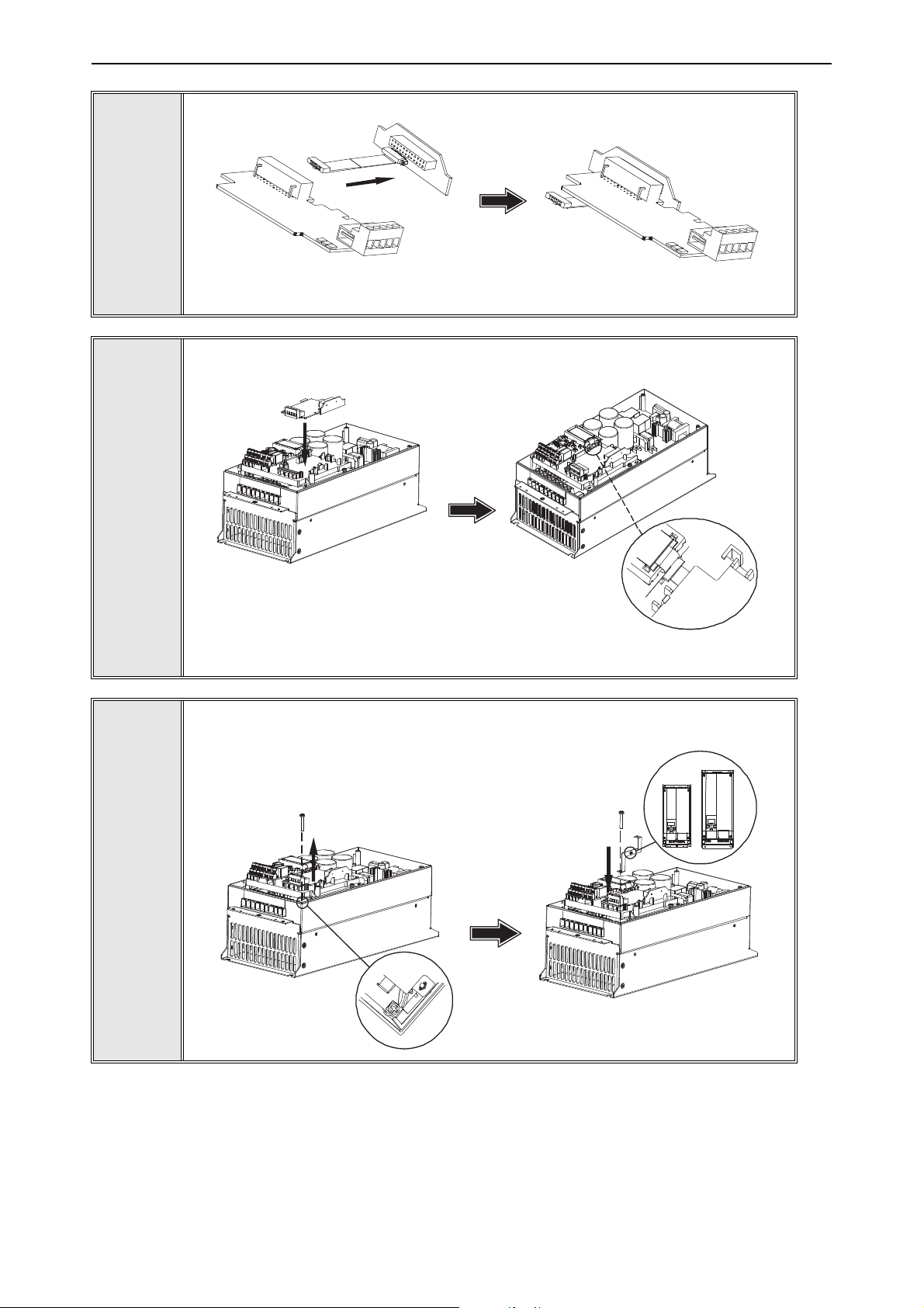
Connect the flat cable from the option board mounting frame to VACON® 20.
4
11557A_00
If a cable strain relief is required, attach the parts as shown in the figure.
5
11558A_00
5
Local contacts: https://www.danfoss.com/en/contact-us/contacts-list/
Page 21

Installation vacon • 21
11559A_00
11560A_00
Install the option board to the option board
holder. Make sure that the option board is
securely fastened.
6
7
Cut free a sufficiently wide opening for the
option board connector.
Attach the option board cover to VACON
20. Attach the strain relief cable clamp with
screws if needed.
®
11650_00
8
Local contacts: https://www.danfoss.com/en/contact-us/contacts-list/
5
Page 22

vacon • 22 Installation
13006.emf
11562_00
11564_00
5.2.2 Frames MI4, MI5
®
Make sure power is disconnected before opening the VACON
1a: For MI4: Open the cover.
20 cover.
1
2
11561_00
1b: For MI5: Open the cover and release the fan connector.
Connect the flex cable to option board connector PCB.
Local contacts: https://www.danfoss.com/en/contact-us/contacts-list/
5
Page 23
Installation vacon • 23
11565_00
MI 04
MI 05
11567_00
Connect the option board to connector PCB.
3
Attach the option board with connector PCB to VACON® 20 and connect the flex
cable.
4
5
11566_00
Attach a suitable grounding plate to VACON® 20. The grounding plate is marked
with supported enclosure size.
Local contacts: https://www.danfoss.com/en/contact-us/contacts-list/
5
Page 24

vacon • 24 Installation
11568_00
11569_00
11570_00
Assemble a clamp on top of the grounding plate on both sides of the option board.
6
8a: For MI4: Close the cover.
7
8b: For MI5: Remount the fan connector and close the cover.
5
Local contacts: https://www.danfoss.com/en/contact-us/contacts-list/
Page 25

Installation vacon • 25
13006.emf
11643_00
13006.emf
5.3 Installation in VACON® 20 X and 20 CP
Do not add or replace option boards or fieldbus boards on an AC drive with the power
switched on. This may damage the boards.
Open the cover of the drive.
1
MU3 example
The relay outputs and other I/O-terminals may have a dangerous control voltage
present even when the drive is disconnected from mains.
Local contacts: https://www.danfoss.com/en/contact-us/contacts-list/
5
Page 26

vacon • 26 Installation
7089_00
7090_00
7091_007091_00
Remove the option slot cover.
2
Install the option board into the slot as shown in the figure.
3
4
Mount the option slot cover. Remove the plastic opening for the option board
terminals.
5
Local contacts: https://www.danfoss.com/en/contact-us/contacts-list/
Page 27

Installation vacon • 27
M4x55
9174.emf
DANGER
5.4 Installation in VACON® 100 family
Open the cover of the AC drive.
1
The relay outputs and other I/O-terminals may have a dangerous control voltage
present even when VACON
®
100 family AC drive is disconnected from mains.
Local contacts: https://www.danfoss.com/en/contact-us/contacts-list/
5
Page 28

vacon • 28 Installation
3023.emf
DE
3024.emf
Open the inner cover to reveal the option board slots (C,D,E).
2
3
Install the fieldbus board into slot D or E.
NOTE: Incompatible boards cannot be installed on VACON
Compatible boards have a slot coding
that enable the placing of the board.
®
100 family AC drive.
5
4
Then connect the cable to its appropriate OPTEC EtherCAT option board RJ-45
connector.
Local contacts: https://www.danfoss.com/en/contact-us/contacts-list/
Page 29
Installation vacon • 29
9202.emf
Fieldbus
cables
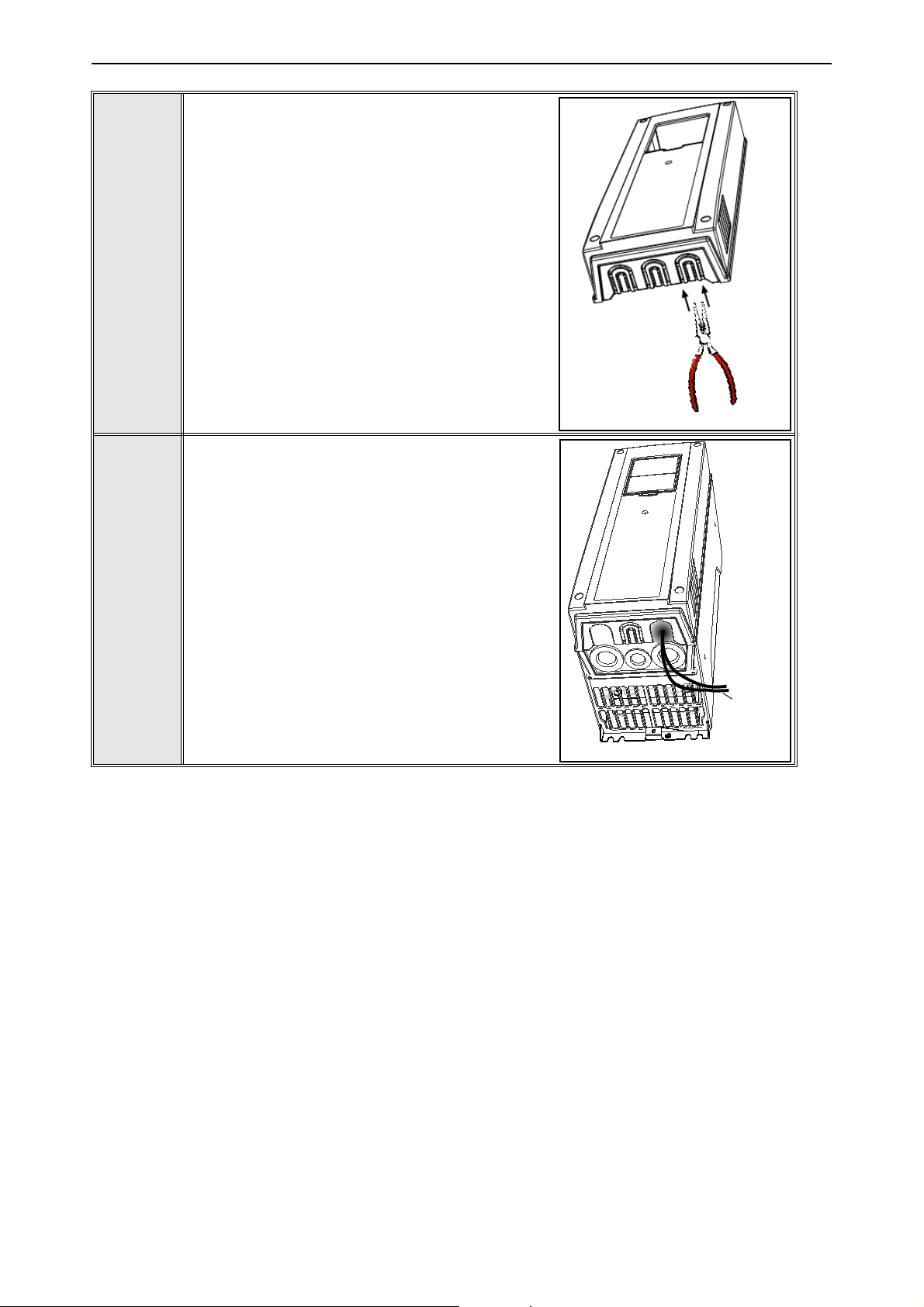
Unless already done for the other control cables,
cut free the opening on the AC drive cover for the
fieldbus cable (protection class IP21).
NOTE: Cut the opening on the same side you
have installed the board in!
5
Remount the AC drive cover and run the cable as
shown in picture.
NOTE: When planning the cable runs, remember
to keep the distance between the fieldbus cable
and the motor cable at a minimum of 30 cm. It is
recommended to route the option board cables
away from the power cables as shown in the picture.
6
Local contacts: https://www.danfoss.com/en/contact-us/contacts-list/
5
Page 30

vacon • 30 Commissioning
6. COMMISSIONING
This chapter explains the configuration of AC drive and EtherCAT master to enable communication
between EtherCAT master and OPTEC EtherCAT option board.
6.1 AC drive and OPTEC EtherCAT option board parametrization
VACON® AC drive and OPTEC EtherCAT option board parameters can be read and modified with AC
®
drive control keypad or with PC tools. See description of VACON
PC tools in Chapter 6.6 "VACON®
PC-tools".
Step 1. Enable field bus control in AC drive to make AC drive to be controllable via field bus. Enabling of field bus control in a different VACON
®
AC drives is described in Chapter 12 "APPENDIX D
- FIELDBUS PARAMETRISATION".
If OPTEC EtherCAT is used only for monitoring and data collection purposes, then Step 1 is no required.
Step 2. Parametrize OPTEC EtherCAT option board and monitor option board status.
•In case of VACON
•In case of VACON
®
NXP parameters are located under the menu M7 Expander boards menu.
®
100 family parameters are located under the menu M5 I/O and Hardware
menu.
Minimum AC drive firmware version required by OPTEC EtherCAT parameter and monitor value
functionality is described in the following table. With older control firmware versions, the parameters and monitor values are not available. In this case parametrization must be done via EtherCAT
bus.
Table 15. EtherCAT parameters and monitor value support
AC drive AC drive SW version
From OPTEC EtherCAT
SW version
®
100 INDUSTRIAL
VACON
VACON
®
and 100 X
VACON® 100 FLOW
®
VACON
20 X and CP
VACON
NXP
®
20
NXP00002V196 OPTEC_FW0128V003
FW0072V029 OPTEC_FW0128V003
FW0159V019 OPTEC_FW0128V003
To be defined OPTEC_FW0128V003
To be defined OPTEC_FW0128V003
6.1.1 Option board parameters
OPTEC EtherCAT can be parametrized with a following option board parameters. Option board parameters are stored into AC drive permanent memory. It is possible to backup and restore AC drive
parameters. See details of backup and restore operation in AC drive user manual.
Using of parameters is optional, OPTEC EtherCAT can be fully parametrized by EtherCAT master.
In this case parameters are set into default values.
Table 16. OPTEC EtherCAT Parameters
Name Default Range Description
6
Operation mode Drive Profile
Drive Profile (1),
Bypass (2)
Local contacts: https://www.danfoss.com/en/contact-us/contacts-list/
Operation mode defines how EtherCAT
master can control the motor.
Page 31

Commissioning vacon • 31
Table 16. OPTEC EtherCAT Parameters
Name Default Range Description
Comm. Timeout 0 s 0…65535 s Communication timeout in seconds
Station Alias 0 0…65535
Device ID 1 1...65535 Device ID of OPTEC EtherCAT
Vl setpoint factor 1 1, 10, 100
6.1.1.1 Operation mode
Operation mode parameter defines how EtherCAT master can control the motor and monitor the
motor control status.
• Drive Profile means CiA-402 Drive and Motion Control Profile's Velocity mode.
• Bypass means VACON
See details of operation mode in Chapter 7.3 "Operating modes".
®
specific control mode
Configured Station Alias for OPTEC
EtherCAT.
Scaling factor for vl speed reference
(only in NXP).
Operation mode can be selected with a following methods that are described in Chapter 6.3 "Operation mode selection". Latest modification is taken into use and currently used setting is stored into
Operation mode parameter. Currently used Operation mode can be seen in Operation mode monitor
value.
• Operation mode selection with parameter
• Operation mode selection by writing into 0x6060 CiA-402 Modes of Operation object. See
details in Chapter 7.2.26 "CiA 402 Modes of Operation".
• Operation mode selection with PDO assignment. See details in Chapter 6.3.3 "Operation
mode selection using PDO assignment".
NOTE! If EtherCAT master assigns only Bypass specific process data objects and CiA-402 specific
process data objects (RxPDO 0x1600, TxPDO 0x1A00) are not assigned then selecting of Drive Profile is not possible.
NOTE! In CiA-402 Drive Profile mode it is recommended to set AC drive's "Fieldbus min scale" and
"Fieldbus max scale" parameters value to zero. In otherwise RPM scaling does not work properly.
Part of NXP applications contains "Fieldbus min scale" and "Fieldbus max scale" settings. In
APFIFF06 Multipurpose application these parameters can be found from menu P2.9.1 and P2.9.2.
6.1.1.2 Communication timeout
Communication timeout parameter defines wait time in seconds for fault activation.
In EtherCAT communication EtherCAT master typically defines SM watchdog time to the EtherCAT
slave device. If OPTEC EtherCAT cannot receive process data from EtherCAT master within SM
watchdog time, then it activates F53 Field bus fault.
With Communication timeout parameter it is possible to extend the time when F53 field bus fault is
activated.
• If Communication timeout is 0 then F53 field bus fault is activated after SM watchdog time
• If Communication timeout is other than 0 then F53 field bus fault is activated after SM
watchdog time + Communication timeout time (seconds)
See details of communication time out behavior in Chapter 8.3 "Fieldbus timeout fault (F53)".
Local contacts: https://www.danfoss.com/en/contact-us/contacts-list/
6
Page 32

vacon • 32 Commissioning
6.1.1.3 Station alias
Station Alias parameter defines Configured Station Alias for OPTEC EtherCAT. EtherCAT master
devices can use the alias for node addressing. Usage of the alias is optional for the master device.
• If Station alias parameter is 0 then OPTEC uses Configured Station Alias defined by EtherCAT master. EtherCAT master (PLC or EtherCAT configuration tool) can write Configured
Station Alias to OPTEC EtherCAT EEPROM. New alias is taken into use after power cycle of
variable-frequency drive.
• If Station alias parameter is other than 0 then OPTEC EtherCAT uses Configured Station
Alias defined by AC drive panel parameter. New alias is taken into use immediately after
change.
See more about Configured Station Alias in Chapter 6.2.3 "Addressing and identification".
6.1.1.4 Device ID
This parameter can be used to set the unique device identification value for OPTEC EtherCAT within
the EtherCAT network. EtherCAT master needs to be configured to use this identification method.
If EtherCAT master does not use Device ID as identification method, this parameter has no effect.
More detailed description is found in Chapter 6.2.3 "Addressing and identification".
6.1.1.5 Vl setpoint factor
If the default RPM range of vl target velocity and vl velocity actual in not enough for high speed applications, this parameter can be used to increase the range by 10 or 100. The default speed range
with vl setpoint factor 1 is -32768...+32767 RPM. With vl scaling factor 10 this is -327680...327670.
In practice, this means that vl target velocity value of 100 RPM translates to 1000 RPM internally
and vl velocity actual value of 100 RPM needs to be multiplied by 10 to get actual RPM of the drive.
NOTE! This panel parameter is only visible in VACON
6.1.2 Option board monitor values
OPTEC EtherCAT option board monitor values tells useful information about the option board status.
Table 17. OPTEC EtherCAT monitor values
Name Range Description
Initializing (1),
Stopped (2),
FB Protocol Status
EtherCAT Run
Communication status 0.0…6553.9
Operate Mode
Operational (3),
Faulted (4),
Failing (5),
Pre-Operational (6)
Init (1),
Pre-Operational (3),
Safe-Operational
(4),
Operational (5)
None (1),
Drive Profile (2),
Bypass (3)
®
NXP drives.
Generic communication status
EtherCAT RUN indicator
Number of successfully received process data
frames and error frames during a second.
Currently used Operate mode
6
Local contacts: https://www.danfoss.com/en/contact-us/contacts-list/
Page 33

Commissioning vacon • 33
Table 17. OPTEC EtherCAT monitor values
Name Range Description
AL Status Code 0x0…0xFFFF EtherCAT AL Status Code
SM Watchdog 0…65535 SM Watchdog time in milliseconds
Station Alias 0…65535 Currently used Configured Station Alias
Drive control word - Control word in drive format
Drive status word - Status word in drive format
Protocol control word - Control word in protocol format
Protocol status word - Status word in protocol format
Sub menu: ESI Selection
Mode
Off (1),
ESI Selection Mode
Product Code 0…0xFFFFFFFF Currently used EtherCAT Product Code
Revision Number 0…0xFFFF Currently used EtherCAT Revision Number
Sub menu EoE
Automatic (2),
Static (3)
ESI file selection mode
IP part 1 0-255 IP address part 1
IP part 2 0-255 IP address part 2
IP part 3 0-255 IP address part 3
IP part 4 0-255 IP address part 4
Subnet P1 0-255 Subnet mask part 1
Subnet P2 0-255 Subnet mask part 2
Subnet P3 0-255 Subnet mask part 3
Subnet P4 0-255 Subnet mask part 4
Default GW P1 0-255 Gateway IP address part 1
Default GW P2 0-255 Gateway IP address part 2
Default GW P3 0-255 Gateway IP address part 3
Default GW P4 0-255 Gateway IP address part 4
EoE Enabled / Disabled Shows if EoE is enabled or disabled by master
6.1.2.1 FB Protocol status
FB Protocol status monitor value shows generic status of field bus. When device has started, it
stays in "Initializing" status until the connection is opened to the device.
When EtherCAT master commands OPTEC EtherCAT to Pre-Operational or Safe-Operational state
then the status changes to "Pre-Operational".
When EtherCAT master commands OPTEC EtherCAT to Operational state then the status changes
to "Operational".
See EtherCAT state machine states in Chapter 2 "OPTEC EtherCAT - General".
If the connection is closed or lost, the status changes to "Failing" until communication time out time
has elapsed. Then the status changes to "Faulted". See details of communication time out behavior
in Chapter 8.3 "Fieldbus timeout fault (F53)".
Local contacts: https://www.danfoss.com/en/contact-us/contacts-list/
6
Page 34

vacon • 34 Commissioning
6.1.2.2 EtherCAT Run
EtherCAT Run monitor value shows EtherCAT state. See EtherCAT state machine states in
Chapter 2 "OPTEC EtherCAT - General". When device has started, it stays in "Initialisation" state
until the connection is opened to the device.
State is changed to "Initialisation", "Pre-operational", "Safe-operational", or "Operational" when
EtherCAT master commands OPTEC EtherCAT to move into these states.
OPTEC EtherCAT moves from "Operational" to "Safe-operational" when it cannot get process data
from EtherCAT master within time defined by SM Watchdog time.
Bootstrap state is not supported at a moment in OPTEC EtherCAT.
6.1.2.3 Communication status
Communication status monitor value is shown in format "nnnn.y":
• nnnn shows number of successfully received process data frames during a second
• y shows number of error frames during a second. Processing of these frames failed.
NOTE! When using virtual EtherCAT master in PC workstation non-EtherCAT data frames might be
passed to the Ethernet interface in which OPTEC EtherCAT is connected to. In this case the diagnostic shows that OPTEC EtherCAT receives error frames.
6.1.2.4 Operate Mode
Operate Mode monitor value shows currently used operate mode.
• None means that operate mode is not defined.
• Drive Profile means CiA-402 Drive and Motion Control Profile's Velocity mode.
• Bypass means VACON specific control mode.
6.1.2.5 AL Status Code
AL Status Code value shows OPTEC EtherCAT option board's EtherCAT Application Layer status
which might tell information about possible EtherCAT communication or configuration problem.
Acronyms I, P, S, O, E on the table below describes EtherCAT states: Initialization, Pre-operational,
Safe-operational, Operational, Error. See EtherCAT state machine states in Chapter 2 "OPTEC EtherCAT - General".
Table 18. EtherCAT AL Status Codes
Code Description
0x0000 No error Any Current state
0x0001 Unspecified error Any I + E, P + E, S + E
0x0002 No memory Any I + E, P + E, S + E
Current state or
state changes
Resulting state
6
0x0003 Invalid device setup P -> S P + E
0x0011 Invalid requested state change
0x0012 Unknown requested state Any I +E, P + E, S + E
0x0013 Bootstrap not supported I -> B I + E
0x0014 No valid firmware I -> P I + E
0x0015 Invalid mailbox configuration I -> B I + E
0x0016 Invalid mailbox configuration I -> P I + E
Local contacts: https://www.danfoss.com/en/contact-us/contacts-list/
I -> S, I -> O, P -> O,
O -> B, S -> B, P -> B
I +E, P + E, S + E
Page 35

Commissioning vacon • 35
Table 18. EtherCAT AL Status Codes
Code Description
0x0017 Invalid sync manger configuration P -> S, S -> O Current state + E
0x0018 No valid inputs available S, O, S -> O S + E
0x0019 No valid outputs O, S -> O S + E
0x001A Synchronization error O, S -> O S + E
0x001B Sync manager watchdog O, S S + E
0x001C Invalid Sync Manager Types O, S, P -> S S + E
0x001D Invalid Output Configuration O, S, P -> S P + E
0x001E Invalid Input Configuration O, S, P -> S P + E
0x001F Invalid Watchdog Configuration O, S, P -> S P + E
0x0020 Slave needs cold start Any I + E, P + E, S + E
0x0021 Slave needs INIT B, P, S, O I + E, P + E, S + E
0x0022 Slave needs PREOP S, O S + E
0x0023 Slave needs SAFEOP O S + E
0x0024 Invalid Input Mapping P -> S P + E
0x0025 Invalid Output Mapping P -> S P + E
0x0026 Inconsistent Settings P -> S P + E
Current state or
state changes
Resulting state
0x0027 Freerun not supported P -> S P + E
0x0028 SyncMode not supported P -> S P + E
0x0029 Freerun needs 3 buffer mode P -> S P + E
0x002A Background Watchdog S, O P + E
0x002B No Valid Inputs and Outputs O, S -> O S + E
0x002C Fatal Sync Error O S + E
0x002D No Sync Error S -> O S + E
0x0030 Invalid DC SYNC Configuration O, S -> O, P -> S P + E, S + E
0x0031 Invalid DC Latch Configuration O, S -> O, P -> S P + E, S + E
0x0032 PLL Error O, S -> O S + E
0x0033 DC Sync IO Error O, S -> O S + E
0x0034 DC Sync Timeout Error O, S -> O S + E
0x0035 DC Invalid Sync Cycle Time P -> S P + E
0x0036 DC Sync0 Cycle Time P -> S P + E
0x0037 DC Sync1 Cycle Time P -> S P + E
0x0041 MBX_AOE B, P, S, O I + E, P + E, S + E
0x0042 MBX_EOE B, P, S, O I + E, P + E, S + E
0x0043 MBX_COE B, P, S, O I + E, P + E, S + E
0x0044 MBX_FOE B, P, S, O I + E, P + E, S + E
0x0045 MBX_SOE B, P, S, O I + E, P + E, S + E
0x004F MBX_VOE B, P, S, O I + E, P + E, S + E
0x0050 EEPROM no access Any I + E, P + E, S + E
0x0051 EEPROM Error Any I + E, P + E, S + E
Local contacts: https://www.danfoss.com/en/contact-us/contacts-list/
6
Page 36

vacon • 36 Commissioning
Table 18. EtherCAT AL Status Codes
Code Description
Current state or
state changes
Resulting state
0x0060 Slave restarted locally Any I
0x0061 Device Identification value updated P P + E
6.1.2.6 SM Watchdog
SM Watchdog monitor value tells SM watchdog time in milliseconds. If usage of SM watchdog is
configured into EtherCAT master device then the master configures this time the to EtherCAT slave
devices before process data communication is started.
See setting of SM watchdog in Chapter 6.2.4 "Setting the watchdog".
6.1.2.7 Station Alias
Station Alias monitor value shows currently used Configured Station Alias. EtherCAT master devices can use the alias for node addressing.
See setting of the alias in Chapter 6.2.3.2 "Configured station alias".
6.1.2.8 Drive control word
Drive control word monitor value shows the control word in AC drive specific format. In most cases
®
the control word is transferred to AC drive in VACON
format which is described in Chapter 11 "AP-
PENDIX C - CONTROL AND STATUS WORD".
If PROFIdrive operate mode is used, then OPTEC EtherCAT converts the control word into VACON
®
format before transmitting it to the application. In Bypass mode PLC can send the control word in
a special application specific format to the application.
6.1.2.9 Drive status word
Drive status monitor value shows the status word in AC drive specific format. In most cases the sta-
®
tus word is transferred from AC drive application to OPTEC EtherCAT in VACON
format which is
described in Chapter 11 "APPENDIX C - CONTROL AND STATUS WORD".
If CiA-402 Drive Profile operate mode is used, then OPTEC EtherCAT converts the status word into
CiA-402 Drive Profile format before transmitting it to the PLC. In Bypass mode AC drive application
can send the status word in a special application specific format to OPTEC EtherCAT which then
passed the status word to the PLC.
6.1.2.10 Protocol control word
Protocol control word monitor value shows the control word that was received from EtherCAT master.
If Operate mode is "Drive Profile" then control word is in CiA-402 format. See CiA-402 Drive profile
mode.
If Operate mode is "Bypass" then control word is usually in VACON
®
specific format. See Chapter 11
"APPENDIX C - CONTROL AND STATUS WORD". Special applications might use other formats.
6.1.2.11 Protocol status word
Protocol status word monitor value shows the status word that OPTEC EtherCAT option board
sends to EtherCAT master.
If Operate mode is "Drive Profile" then status word is in CiA-402 format. See CiA-402 Drive profile
mode.
If Operate mode is "Bypass" then status word is usually in VACON
®
specific format. See Chapter 11
"APPENDIX C - CONTROL AND STATUS WORD". Special applications might use other formats.
6
Local contacts: https://www.danfoss.com/en/contact-us/contacts-list/
Page 37

Commissioning vacon • 37
6.1.2.12 ESI Selection Mode
ESI Selection Mode shows currently used ESI Selection Mode. See details of this functionality in
Chapter 6.4 "ESI file selection".
6.1.2.13 Product Code
Product Code monitor value shows currently used EtherCAT Product Code. It affects into automatic
selection of Slave Information (ESI) file in EtherCAT master configuration tools. See details of this
functionality in Chapter 6.4 "ESI file selection".
6.1.2.14 Revision Number
Revision Number monitor value shows currently used EtherCAT Revision Number. It affects into
automatic selection of Slave Information (ESI) file in EtherCAT master configuration tools. See details of this functionality in Chapter 6.4 "ESI file selection".
6.1.2.15 IP part 1
The most significant byte of OPTEC IP address.
6.1.2.16 IP part 2
Second byte of OPTEC IP address.
6.1.2.17 IP part 3
Third byte of OPTEC IP address.
6.1.2.18 IP part 4
The least significant byte of OPTEC IP address.
6.1.2.19 Subnet mask P1
The most significant byte of OPTEC subnet mask.
6.1.2.20 Subnet mask P2
Second byte of OPTEC subnet mask.
6.1.2.21 Subnet mask P3
Third byte of OPTEC subnet mask.
6.1.2.22 Subnet mask P4
The least significant byte of OPTEC subnet mask.
6.1.2.23 Default GW IP P1
The most significant byte of default gateway IP address.
6.1.2.24 Default GW IP P2
Second byte of default gateway IP address.
6.1.2.25 Default GW IP P3
Third byte of default gateway IP address.
6.1.2.26 Default GW IP P4
The least significant byte of gateway IP address.
6.1.2.27 EoE
Status of Ethernet over EtherCAT. Shows “Enabled” if OPTEC EoE is activated by master and other
monitor values (IP part 1 etc) are valid. If status is “Disabled” OPTEC has no valid IP address and it
cannot be connected via VACON
Local contacts: https://www.danfoss.com/en/contact-us/contacts-list/
®
live for example.
6
Page 38

vacon • 38 Commissioning
6.2 EtherCAT master configuration
EtherCAT master (PLC) is typically connected to OPTEC EtherCAT option board with a following procedure.
Step 1. Import EtherCAT Slave Information files (ESI files) into EtherCAT master configuration tool.
Step 2. Connect EtherCAT master to OPTEC EtherCAT option board.
Step 3. Configure connection to OPTEC EtherCAT.
6.2.1 Importing OPTEC EtherCAT ESI files
ESI file defines slave device's functionality and object list to EtherCAT master device. Using of ESI
files is optional, but eases data mapping between EtherCAT master and EtherCAT slave.
OPTEC EtherCAT option board ESI files can be downloaded from https://www.danfoss.com/en/service-and-support/ -> Software -> Select “Drives” as Business unit -> Fieldbus configuration files.
• OPTEC_VACON_OPTEC_Vxx_yyyymmdd.xml is generic ESI file for OPTEC option. It can be
used with all VACON
objects for accessing of application specific IDs.
• AC drive and AC drive application specific ESI files (for example
OPTEC_VACON_NX_ALLINONE_yyyymmdd.xml) defines CoE objects for accessing of application specific parameters.
NOTE! Application specific parameters can be accessed even when ESI file does not does not define
CoE objects for them. See details in Chapter 7.4 "Accessing drive parameters via CoE MailBox".
®
AC drives and AC drive applications. This ESI file does not define CoE
ESI files must be imported to the PC hard disk from where EtherCAT master configuration tool can
find them. In some case restart of EtherCAT master configuration tool is required before new ESI
files are taken into use.
• In case of TwinCAT 2.x ESI file default location is: C:\TwinCAT\Io\EtherCAT
• In case of TwinCAT 3.x ESI file default location is: C:\TwinCAT\3.x\Config\Io\EtherCAT
• In case of CODESYS V3.x ESI file is selected as part of EtherCAT slave device importing process. See Chapter 6.2.2.3 "Slave scan in CODESYS V3.x"
See more about ESI file selection logic in Chapter 6.4 "ESI file selection".
6.2.2 Establishing connection to OPTEC EtherCAT
The following chapters shows scanning of OPTEC EtherCAT option board in TwinCAT 2.x and TwinCAT 3.x.
6.2.2.1 Slave scan in TwinCAT 2.x
Connect the Ethernet cable from the Ethernet card of the computer to the IN
1
Connector of the OPTEC Option Board EtherCAT (for more information see
Chapter 4.1 "Layout and connections").
6
Local contacts: https://www.danfoss.com/en/contact-us/contacts-list/
Page 39

Commissioning vacon • 39
Start the TwinCAT System Manager by right-clicking on the toolbar icon and by
selecting ‘System Manager’.
2
3
In the TwinCAT System Manager, go to ‘Options’ -> ‘Show Real Time Ethernet
Compatible Devices…’
Local contacts: https://www.danfoss.com/en/contact-us/contacts-list/
6
Page 40

vacon • 40 Commissioning
In the first phase your Ethernet card is shown under "Incompatible devices". Select the card and click "Install". After this operation the card is visible under "Installed and ready to use devices.
4
5
6
Make sure that TwinCAT is in the Config mode (check that the text Config mode is
visible in the bottom right corner).
If this is not the case, switch the TwinCAT System Manager to the Config Mode by
clicking 'Set/Reset TwinCAT to Config Mode'.
6
7
8
In the 'Load I/O devices?' dialog, click 'Yes'.
In the 'Active Free Run?' dialog, click 'No'
Local contacts: https://www.danfoss.com/en/contact-us/contacts-list/
Page 41

Commissioning vacon • 41
9
10
Start a new project by clicking 'New' from the toolbar or by clicking 'File' -> 'New'.
Scan the devices by right-clicking on top of the 'I/O devices' tree item and by selecting 'Scan Devices…'.
11
12
13
Select the Ethernet card used for communication with the OPTEC Option Board
(the Ethernet card which is connected to the IN connector of the OPTEC Option
Board), and click 'OK'.
In the 'Scan for boxes?' dialog, click 'Yes'.
To switch the EtherCAT bus to OPERATIONAL state, click 'Yes' in the 'Activate
free run?' dialog.
Local contacts: https://www.danfoss.com/en/contact-us/contacts-list/
6
Page 42

vacon • 42 Commissioning
When the connection has been established, TwinCAT looks like in the picture below.
14
6
Local contacts: https://www.danfoss.com/en/contact-us/contacts-list/
Page 43

Commissioning vacon • 43
6.2.2.2 Slave scan in TwinCAT 3.x
Connect the Ethernet cable from the Ethernet card of the computer to the IN Con-
1
nector of the OPTEC EtherCAT option board. For more information see Chapter 4
"Layout and connections".
Open TwinCAT XAE program from Windows Programs folder.
2
3
4
Define Ethernet interface for TwinCAT by opening “TWINCAT” -> “Show Realtime
Ethernet Compatible Devices…”
From the list, select the Ethernet interface in which EtherCAT master is connected. After that, select “Install”.
Local contacts: https://www.danfoss.com/en/contact-us/contacts-list/
6
Page 44
vacon • 44 Commissioning
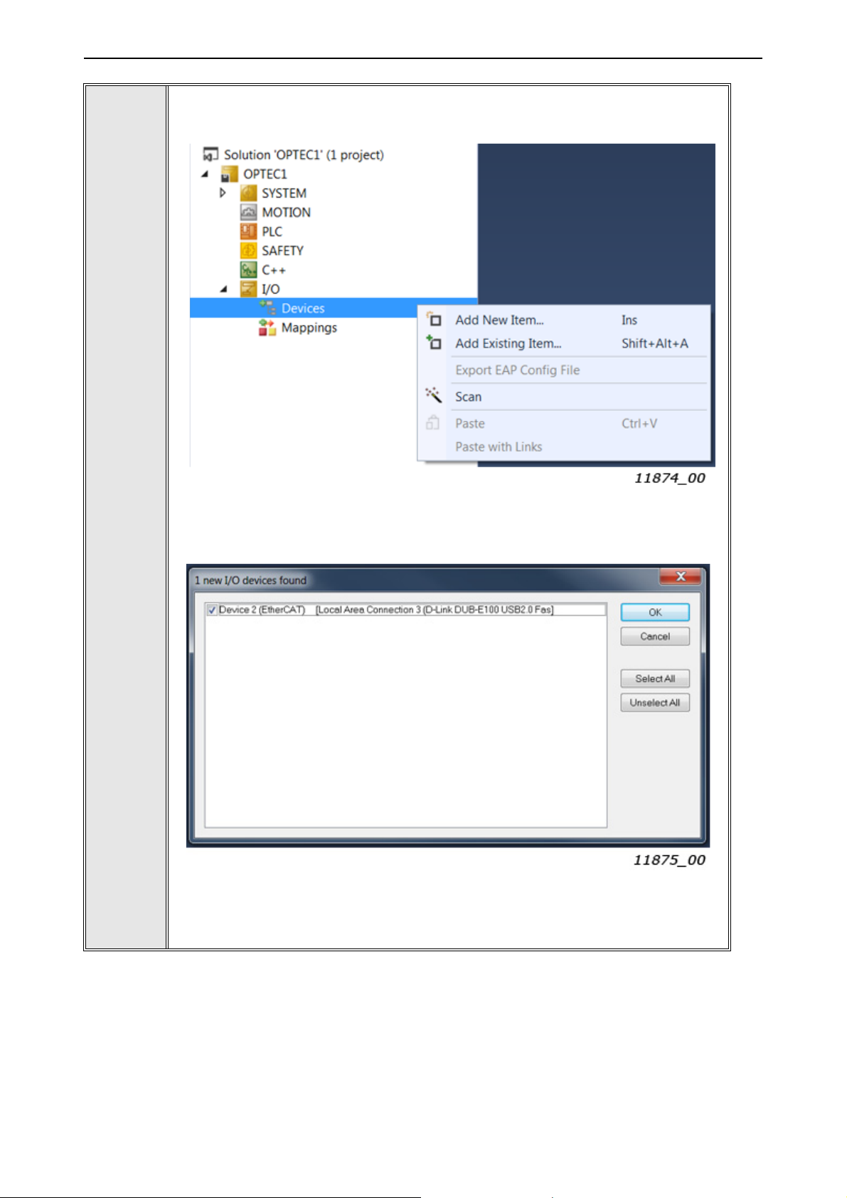
In Solution Explorer, add EtherCAT master to the project. EtherCAT master can
be searched by scanning (see A below). Alternatively, EtherCAT master can be
added with "Add New Item…" option (see B below).
5
5A. In case of scanning TwinCAT shows Ethernet interface which is connected to
EtherCAT devices. Select the interface and press “OK”.
5B. In case of "Add New Item…" select "EtherCAT master" device from the list and
press “OK”.
6
Local contacts: https://www.danfoss.com/en/contact-us/contacts-list/
Page 45

Commissioning vacon • 45
After this TwinCAT shows list of Ethernet interfaces. Select the interface in which
EtherCAT master device is connected and press “OK”.
6
Set TwinCAT into configuration mode. Press “OK” to the following "Restart TwinCAT System in Config Mode" and "Load I/O Devices" queries.
7
Local contacts: https://www.danfoss.com/en/contact-us/contacts-list/
6
Page 46
vacon • 46 Commissioning
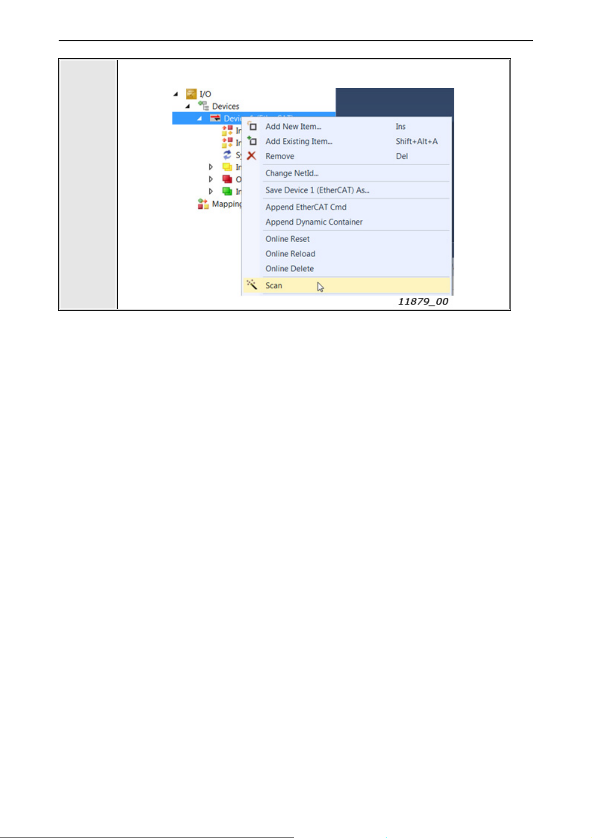
Scan Ethernet boxes (slave devices) by pressing right mouse key over EtherCAT
master device. After that select "Scan".
8
6
Local contacts: https://www.danfoss.com/en/contact-us/contacts-list/
Page 47

Commissioning vacon • 47
New EtherCAT slave box should appear into menu tree if TwinCAT finds a correct
ESI file for the device.
If TwinCAT cannot find ESI file for the device then it is possible to use object online
description. Press “Yes” for online description query. After that "OPTEC" box
should appear into menu tree.
9
Local contacts: https://www.danfoss.com/en/contact-us/contacts-list/
6
Page 48

vacon • 48 Commissioning
6.2.2.3 Slave scan in CODESYS V3.x
Make sure WinPCAP Ethernet drivers are installed into your PC. Scanning of
1
2
EtherCAT slave devices with CODESYS virtual EtherCAT master is going to fail
without WinPCAP driver.
Open Gateway configuration file which is located in C:\Program Files (x86)\3S
CODESYS\GatewayPLC\ CODESYSControl.cfg. Then add "SysEthernet" component into Component manager.
[ComponentManager]
Component.1=CmpTargetVisuStub
Component.2=CmpWebServer
Component.3=CmpWebServerHandlerV3
Component.4=SysEthernet
;Component.4=CmpHilscherCIFX
;Component.5=CmpPCANBasicDrv
Start "CODESYS V.3x" program and select "New Project..."
3
6
Local contacts: https://www.danfoss.com/en/contact-us/contacts-list/
Page 49

Commissioning vacon • 49
Select for example "Standard Project" as a base project and write name for the
project. Then press "OK".
4
Local contacts: https://www.danfoss.com/en/contact-us/contacts-list/
6
Page 50

vacon • 50 Commissioning
Select "Tools" -> "Device Repository..." menu. Then click "Install..." and select
ESI file for OPTEC EtherCAT.
NOTE! In this example generic OPTEC_VACON_OPTEC_Vxx_yyyymmdd.xml ESI
file is used. As a result, OPTEC EtherCAT is shown in CODESYS with name "OPTEC". The device name is different when using drive and application specific ESI
file.
After selecting the ESI file the device is added into "Installed devices" list. Device
Repository can be now closed.
5
6
Double click "Device (CODESYS Control Win V3)" in Devices list.
6
Local contacts: https://www.danfoss.com/en/contact-us/contacts-list/
Page 51

Commissioning vacon • 51
Check that Gateway module's IP-Address is "localhost". If not, then create a new
Gateway from "Gateway" -> "Add new gateway..." and define localhost address
for it.
7
Check from Windows system tray that CODESYS PLC is running. Click "Start PLC"
if it is in stopped state.
8
9
Select "Scan Network..." and then select the device which is your PC computer.
Then click "OK".
Local contacts: https://www.danfoss.com/en/contact-us/contacts-list/
6
Page 52

vacon • 52 Commissioning
If operation is successful, then Device view shows green color for both Gateway
module and PC computer.
10
Select with right mouse "Device (CODESYS Control Win V3)" -> "Add Device.."
11
12
Select from "Add Device" menu "EtherCAT Master". Then click "Add device" and
close "Add Device menu".
6
Local contacts: https://www.danfoss.com/en/contact-us/contacts-list/
Page 53

Commissioning vacon • 53
EtherCAT_Master should appear into left side Devices menu. Open EtherCAT
master configuration page by double clicking "EtherCAT_Master (EtherCAT Master)".
13
Select Ethernet interface for EtherCAT master by clicking "Browse...". Then select Ethernet interface in which OPTEC EtherCAT is connected to. After that click
"OK" in Select Network Adapter view.
14
After this EtherCAT_Master tab should show your network interface name and
MAC address.
Local contacts: https://www.danfoss.com/en/contact-us/contacts-list/
6
Page 54

vacon • 54 Commissioning
Select with left mouse key "EtherCAT_Master (EtherCAT Master)" -> "Scan for
Devices...". Scan Devices window is opened. Then click "Scan Devices" button
from the left corner of the window.
15
6
Local contacts: https://www.danfoss.com/en/contact-us/contacts-list/
Page 55

Commissioning vacon • 55
EtherCAT device should appear into Scanned Devices list.
CODESYS shows Alias Address of the device. This alias is same as shown in OPTEC EtherCAT's monitor value view (Chapter 6.1.2.7 "Station Alias"). The alias
can be changed by changing the value and then clicking "Assign Address". After
power cycle of VACON
Click "Copy to project".
®
AC drive the new alias is taken into use.
16
17
OPTEC EtherCAT is added under EtherCAT_Master.
Local contacts: https://www.danfoss.com/en/contact-us/contacts-list/
6
Page 56

vacon • 56 Commissioning
6.2.3 Addressing and identification
EtherCAT protocol supports various of different mechanisms for EtherCAT slave device addressing
and identification. Following mechanisms are possible with OPTEC EtherCAT option board:
• Positional addressing where EtherCAT master defines address for each slave device via its
physical position in the communication ring.
• Configured Station Alias which is stored permanently into EtherCAT slave device.
• Device ID value that is loaded to AL status code register upon request from master.
Additionally, EtherCAT master and EtherCAT configuration tool might use following information for
EtherCAT slave device identification:
•Vendor ID
•Product Code
• Revision Number
6.2.3.1 Positional addressing
Part of EtherCAT master devices supports positional addressing where EtherCAT master defines
address for each slave device via its physical position in the communication ring.
For example, Beckhoff TwinCAT supports "Auto-increment" addressing where EtherCAT master
assigns automatically addresses for the slave devices during the start-up phase. The first slave in
the ring has an address of 0 and following the addresses are decremented 0xFFFF(-1), 0xFFFE(-2)
etc.
6.2.3.2 Configured station alias
Configured station alias is stored into permanent memory of EtherCAT slave device. In start-up the
slave device writes the station alias value into EtherCAT register 0x0012, from where it can be read
by the EtherCAT master. The master can then use this unique address for slave device identification
and addressing.
Configured station alias can be set to OPTEC EtherCAT with two methods.
1. EtherCAT master or EtherCAT configuration tool writes configured station alias permanently
into EtherCAT slave device's EEPROM. In startup the EtherCAT slave device loads this address
into its EtherCAT register 0x0012.
2. Configured station alias can be set with Station alias panel parameter. In startup OPTEC EtherCAT writes Station alias panel parameter value into EtherCAT register 0x0012.
Using of Station alias panel parameter might be useful in following cases:
• Special tools for writing EtherCAT slave device EEPROM are not available.
• Configured station alias must be stored into AC drive parameter backup.
OPTEC EtherCAT currently used Configured station alias can be seen in Station alias monitor value.
See monitor and parameter value usage in Chapter 6.1 "AC drive and OPTEC EtherCAT option board
parametrization".
6.2.3.3 Device ID value
Device ID value of OPTEC is set via panel parameter “Device ID”. It is permanently saved to nonvolatile memory and loaded during startup.
6
Local contacts: https://www.danfoss.com/en/contact-us/contacts-list/
Page 57

Commissioning vacon • 57
6.2.3.4 Configured station alias in TwinCAT
Step 1. Beckhoff TwinCAT can write Configured station alias into EtherCAT slave device's EEPROM.
Go to EtherCAT tab -> Advanced Settings… -> ESC Access -> E2PROM -> Configured Station Alias.
In this view TwinCAT also shows EtherCAT slave device's currently used Configured Station Alias.
Figure 6.Configured station alias settings in TwinCAT
Step 2. Select Configured Station Alias as an identification method in General -> Idenfication settings.
Figure 7.EtherCAT slave identification settings in TwinCAT
Local contacts: https://www.danfoss.com/en/contact-us/contacts-list/
6
Page 58

vacon • 58 Commissioning
Step 3. Go to General -> Behaviour menu and make sure that "Check Identification" is checked to
enable Configured station address usage in EtherCAT slave device identification.
Figure 8.Startup check settings in TwinCAT
Step 4. Define Configured Station Alias into EtherCAT tabs "Identification Value" field.
Figure 9. EtherCAT address view in TwinCAT
6.2.3.5 Configured station alias in CODESYS V3.x
Setting of EtherCAT slave devices's Station alias was instructed in Chapter 6.2.2.3 "Slave scan in
CODESYS V3.x" where the Station alias was modified in EtherCAT slave device scanning phase.
Station alias can be selected as EtherCAT slave device identification method in EtherCAT slave device's General settings. By checking "Enable Expert Settings" it is possible to select following startup checking methods:
•Vendor ID
•Product ID
• Revision Number
Station alias can be selected by checking "Optional" settings.
6
Local contacts: https://www.danfoss.com/en/contact-us/contacts-list/
Page 59

Commissioning vacon • 59
Figure 10. EtherCAT slave general settings in CODESYS
6.2.3.6 Device ID in TwinCAT
OPTEC device ID is set via panel. To use it as identification method, check the “Explicit Device Identification (ADO 0x0134)” box as seen in Figure 11.
Figure 11.
Also tick the box “Check Identification” as shown in figure 8 and set the “Identification value” to one
set on panel as shown in figure 9. Now master is configured to use device ID as identification method.
6.2.3.7 Other identification methods
EtherCAT master and configuration tools might use following information for EtherCAT slave device
identification. For example, EtherCAT configuration tools might use this information for automatic
ESI file selection for the EtherCAT slave device.
• Vendor ID. In case of OPTEC EtherCAT it is value 144.
• Product Code. By default, OPTEC EtherCAT uses value 17731. The value can be modified.
• Revision Number. By default, OPTEC uses value 1. The value can be modified.
See modification of Product Code and Revision Number in Chapter 6.4 "ESI file selection".
Local contacts: https://www.danfoss.com/en/contact-us/contacts-list/
6
Page 60

vacon • 60 Commissioning
6.2.4 Setting the watchdog
OPTEC EtherCAT supports SM watchdog (SyncManager Watchdog). The SM watchdog is a timer
which is reset after each successful EtherCAT process data communication. If OPTEC EtherCAT
cannot successfully receive process data within SM watchdog time, then Fieldbus timeout fault
(F53) is activated. See details in Chapter 8.3 "Fieldbus timeout fault (F53)".
OPTEC EtherCAT can be used without SM watchdog time. If SM watchdog time is not defined, then
Fieldbus timeout fault is not activated at all because of interrupted process data communication.
EtherCAT master sets SM watchdog time to EtherCAT slave devices. In a following Example TwinCAT sets SM watchdog time 40ms to OPTEC EtherCAT.
Figure 12. TwinCAT SM Watchdog configuration
6.2.5 Sync unit assignment
Assignment of separate sync units for EtherCAT slave devices is needed in case where automation
system must continue operation even when part of EtherCAT slave devices fails.
Sync unit is a module which defines the process data transfers between EtherCAT master and
EtherCAT slave devices. It ensures that process data is exchanged synchronously and consistently
with all EtherCAT slave devices. If one or more EtherCAT slave devices fails during the process data
transfer, then EtherCAT master stops process control to the whole sync unit segment. In this case
WcState (working counter) of every EtherCAT slave device is set to 1 which means invalid working
counter.
In a following TwinCAT example two OPTEC EtherCAT slave devices are assigned into two separated
sync units: Sync unit 1 and Sync unit 2. With this configuration, Sync unit 2 can continue operation
6
Local contacts: https://www.danfoss.com/en/contact-us/contacts-list/
Page 61

Commissioning vacon • 61
even when one device in Sync unit 1 fails. TwinCAT sync unit configuration can be done from EtherCAT master's Sync Unit Assigment settings.
Figure 13. TwinCAT Sync Unit Assigment
Local contacts: https://www.danfoss.com/en/contact-us/contacts-list/
6
Page 62

vacon • 62 Commissioning
6.3 Operation mode selection
Operation mode defines how EtherCAT master can control the motor and monitor the motor control
status. OPTEC EtherCAT supports following modes:
• Drive Profile means CiA-402 Drive and Motion Control Profile's Velocity mode. This mode is
enabled by default.
• Bypass means VACON specific control mode.
See detailed description of these modes in Chapter 7.3 "Operating modes".
Operation mode can be selected with three different methods that are described in following chapters. Latest modification is taken into use and currently used setting is stored into Operation mode
parameter. Currently used Operation mode can be seen in Operation mode monitor value
(Chapter 6.1.2 "Option board monitor values").
NOTE! If EtherCAT master assigns only Bypass specific process data objects and CiA-402 specific
process data objects (RxPDO 0x1600, TxPDO 0x1A00) are not assigned then selecting of Drive Profile is not possible.
NOTE! In CiA-402 Drive Profile mode it is recommended to set AC drive's "Fieldbus min scale" and
"Fieldbus max scale" parameters value to zero. In otherwise RPM scaling does not work properly.
Part of NXP applications contains "Fieldbus min scale" and "Fieldbus max scale" settings. In
APFIFF06 Multipurpose application these parameters can be found from menu P2.9.1 and P2.9.2.
6.3.1 Operation mode selection using parameter
Operation mode can be selected with AC drive keypad parameter. See details in Chapter 6.1.1 "Option board parameters".
6.3.2 Operation mode selection using CoE object
Operation mode can we selected by writing into 0x6060 CiA-402 Modes of Operation CoE object. See
details in Chapter 7.2.26 "CiA 402 Modes of Operation".
6.3.3 Operation mode selection using PDO assignment
Operation mode can we selected with a different PDO assignments. CiA-402 drive profile can be activated by assigning CiA-402 specific process data objects in EtherCAT master. Bypass profile can
be activated by assigning only bypass specific process data objects in EtherCAT master.
6.3.3.1 Swithcing to CiA-402 Drive Profile Mode
Establish the connection to EtherCAT bus as instructed in Chapter "".
1
6
Local contacts: https://www.danfoss.com/en/contact-us/contacts-list/
Page 63

Commissioning vacon • 63
In the tree on the left side, select the desired OPTEC Option Board, and select the
'Process data' tab.
2
3
Under 'Inputs', select the PDO Assignment ‘0x1A00’. Under 'Outputs', select the
PDO Assignment ‘0x1600’.
Local contacts: https://www.danfoss.com/en/contact-us/contacts-list/
6
Page 64

vacon • 64 Commissioning
Make sure that 'PDO Assignment' and 'PDO Configuration' are selected.
4
5
6
7
8
9
Reset TwinCAT to configuration mode by clicking 'Set/Reset TwinCAT config
mode' from the toolbar.
In the 'Restart TwinCAT System in Config Mode' dialog, click 'OK'.
In the 'Load I/O Devices' dialog, click 'Yes'.
In the 'Activate Free Run' dialog, click 'Yes'.
To verfiy that the OPTEC Option Board is in the Bypass mode, select the 'CoE - Online' tab and make sure that there are four subitems under both Can object
groups 'RxPDO' and 'TxPDO'.
Currenly used Operation mode can be seen in Operation mode monitor value. See
Chapter 6.1.2 "Option board monitor values".
Currently used Operation mode can be read with EtherCAT master from CoE object: 0x6061 CiA 402 Modes of Operation Display.
6
Local contacts: https://www.danfoss.com/en/contact-us/contacts-list/
Page 65

Commissioning vacon • 65
6.3.3.2 Swithcing to Bypass mode
1
2
Establish the connection to EtherCAT bus as instructed in Chapter 6.2.2 "Establishing connection to OPTEC EtherCAT".
In the tree on the left side, select the desired OPTEC Option Board, and select
'Process data' tab.
3
Under ‘Inputs’, click to clear the PDO Assignment ‘0x1A00’ checkbox. Under ‘Outputs’, click to clear the PDO Assignment ‘0x1600’ checkbox.
Local contacts: https://www.danfoss.com/en/contact-us/contacts-list/
6
Page 66

vacon • 66 Commissioning
Under ‘Download’, make sure that 'PDO Assignment' and 'PDO Configuration' are
selected.
4
5
6
7
8
9
Reset TwinCAT to configuration mode by clicking 'Set/Reset TwinCAT config
mode' from the toolbar.
In the 'Restart TwinCAT System in Config Mode' dialog, click 'OK'.
In the 'Load I/O Devices' dialog, click 'Yes'.
In the 'Activate Free Run' dialog, click 'Yes'.
To verfiy that the OPTEC Option Board is in the Bypass mode, select the 'CoE - Online' tab and make sure that there are only three subitems under both Can object
groups 'RxPDO' and 'TxPDO'.
Currenly used Operation mode can be seen in Operation mode monitor value. See
Chapter 6.1.2 "Option board monitor values".
Currently used Operation mode can be read with EtherCAT master from CoE object: 0x6061 CiA 402 Modes of Operation Display.
6
Local contacts: https://www.danfoss.com/en/contact-us/contacts-list/
Page 67

Commissioning vacon • 67
6.4 ESI file selection
This chapter tells how the different ESI files can be used with OPTEC EtherCAT. Downloading and
importing of OPTEC EtherCAT ESI files into EtherCAT configuration tool is instructed in
Chapter 6.2.1 "Importing OPTEC EtherCAT ESI files".
EtherCAT configuration tools uses typically Vendor ID, Product Code and Revision Number information to select the correct ESI description for the slave device. OPTEC EtherCAT uses following
settings by default.
•Vendor ID: 144
• Product Code: 17731. The value can be modified.
• Revision Number: 1. The value can be modified.
Currently used Product Code and Revision Number can be seen in OPTEC EtherCAT option board's
monitor values. See details in Chapter 6.1.2 "Option board monitor values".
With default Product Code and Revision Number settings
OPTEC_VACON_OPTEC_Vxx_yyyymmdd.xml ESI file must be always used. Generic
OPTEC_VACON_OPTEC_Vxx_yyyymmdd.xml ESI file can be used with all applications but it does not
define application specific CoE objects. Application specific ESI files defines own CoE objects for application specific data which eases configuration of EtherCAT master.
NOTE! Application specific parameters can be accessed even when ESI file does not does not define
CoE objects for them. See details in Chapter 7.4 "Accessing drive parameters via CoE MailBox".
6.4.1 ESI file selection mode
EtherCAT master can change OPTEC EtherCAT Product Code and Revision Number by writing into
CoE object 0x5FF4.
Figure 14. CiA-402 process data from AC drive
Selection Mode (0x5FF4:1) defines currently used ESI file selection mode. Default value is 0 (OFF).
Content of Static Product Code (0x5FF4:2) and Static Revision Number (0x5FF4:3) fields is used only
when "Static" ESI file selection mode is used.
Table 19. ESI file selection mode
Mode Value Description
OFF 0
Automatic generation is switched off. The product code is set to the
default value 0x4543 and the revision number is set to 1.
Automatic 1
Static 2
After writing new settings to 0x5FF4 CoE object OPTEC EtherCAT must be moved from INIT state to
PREOP state for the change to take effect. This operation can be done with EtherCAT master or
EtherCAT configuration tool, for example with Beckhoff TwinCAT.
Local contacts: https://www.danfoss.com/en/contact-us/contacts-list/
Product Code and Revision Number are generated by using information about the drive and the currently running application.
Product Code and Revision Number defined by Static Product Code
(0x5FF4:2) and Static Revision Number (0x5FF4:3) are used.
6
Page 68

vacon • 68 Commissioning
NOTE! If EtherCAT master or configuration tool uses Product Code and/or Revision Number for
EtherCAT slave device identification, then OPTEC EtherCAT must be scanned again in EtherCAT
master or configuration tool. See Chapter 6.2.2 "Establishing connection to OPTEC EtherCAT".
NOTE! Product Code and Revision Number are stored into EtherCAT slave device's EtherCAT EEPROM. They are not stored into AC drive parameter storage and parameter backup. This means:
• Product Code and Revision Number are not reset with AC drive factory reset
• Product Code and Revision Number are not restored from AC drive parameter backup
6.4.1.1 OFF mode
In OFF mode OPTEC EtherCAT uses Product Code 17731 (0x4543) and Revision Number 1 which
means that generic OPTEC_VACON_OPTEC_Vxx_yyyymmdd.xml ESI file shall be always used.
6.4.1.2 Automatic mode
In the automatic mode, the OPTEC board generates a unique product code. The generated product
code together with the revision number is used by the configuration tool to automatically choose the
correct device description from the ESI file.
The product code depends on the drive type, and the type of the application the drive runs.
OPTEC EtherCAT option board's Product Code and Revision Number can be seen from the monitor
values (Chapter 6.1.2 "Option board monitor values"). Another possibility is to scan EtherCAT network with EtherCAT configuration tool's scanning functionality which usually shows Product Code
and Revision Number of found EtherCAT slave devices.
Read the object 1018 sub-index 2 and 3 To find the product code and revision number, as shown below:
6
Local contacts: https://www.danfoss.com/en/contact-us/contacts-list/
Page 69

Commissioning vacon • 69
If you do not have access to the online description, you can calculate the product code. The method
varies depending on the drive family.
Table 20. Calculating the product code for devices in the V20 and V100 family
Bits Description
Drive family Value Description
31-24
23-16 Not used
Application identifier, which is the unique identification code of the application. The
15-0
Bits Description
31-24
23 Not used
code shows in the name of the application installation file. For example, in the
installation file AMFI1234V567.vcx, 1234 is the application identification code.
Table 21. Calculating the product code for devices in the NX family
V20 0x43 Drive type identifier
V100 0x4d Drive type identifier
Drive family Value Description
NXP 0x50 Drive type identifier
NXS 0x53 Drive type identifier
Bits Name Description
Calculate the value from the country code in the file
name of the installation package. For example, in the
22-13 Country code
12-10 Category
9-0 Application identifier Application identifier consists of the category part and
file ASFIFF01V101.vcx, FI is the country code. Use a
formula with the ASCII values: Country_code =
(ASCII(F) – ASCII(A)) x 26 + (ASCII(I) – ASCII(A))
Category is the non-numerical part of the application
ID. For example, in the file ASFIFF01V101.vcx, FF01 is
the application ID and FF is the category.
Category Value
FF 0
F1
BR 2
EN 3
E4
Q5
C6
S7
the numerical part. For example, in the file
ASFIFF01V101.vcx, FF01is the application identifier. FF
is the category and 01 is the numerical part. The total
length of the application identifier is always 4 characters. A possible variation is, for example, F001.
You must add a device description for every configuration to be supported. Add the new device to
the Devices element in the ESI file.
Local contacts: https://www.danfoss.com/en/contact-us/contacts-list/
6
Page 70

vacon • 70 Commissioning
9459
9462
Enter the calculated product code and the revision number of the application into the ‘ProductCode’
and ‘RevisionNo’ attributes in the Type element of the device, as shown below:
6.4.1.3 Static mode
In the static mode, you define the product code and revision number for the device description. Any
value that is unique in the network is valid as a device description.
In the description file, enter the product code and revision number of your device description in the
Device section.
Make sure the device is in the pre-operational state, and that the selection mode is set to either OFF
or Automatic.
Write the product code and revision number to their respective objects.
Change the selection mode to Static and rescan the network.
6
9463
6.5 Controlling the motor
Controlling of the motor via OPTEC EtherCAT is instructed in this chapter. In this example basic
PDO mapping is used. See detailed description of PDO mapping in Chapter 7.2 "Data Object Descriptions".
Before running the motor, do the following checks:
Local contacts: https://www.danfoss.com/en/contact-us/contacts-list/
Page 71

Commissioning vacon • 71
1. Check that field bus control is enabled in AC drive. Enabling of field bus control in a different VA-
®
AC drives is described in Chapter 12 "APPENDIX D - FIELDBUS PARAMETRISATION".
CON
2. Check that OPTEC EtherCAT is on Operational state.
Figure 15. Online view in TwinCAT
NOTE! If motor is started in Operational state and EtherCAT master commands OPTEC EtherCAT
into other state, then OPTEC EtherCAT activates Fieldbus fault because process data transfer from
EtherCAT master to OPTEC EtherCAT is stopped and motor control is not anymore possible.
• See EtherCAT state machine states in chapter OPTEC EtherCAT - General
• See Fieldbus fault in Chapter 8.3 "Fieldbus timeout fault (F53)"
6.5.1 Controlling in CiA-402 Drive Profile mode
AC drive motor control mode is usually set to "Speed control" when using CiA-402 Drive Profile
mode.
In VACON
Mode -> select "OL Speed Ctrl".
In VACON
• APFIFF06 Multipurpose application: P2.6.1 Motor Ctrl Mode -> select "OL SpeedCont"
• APFIFF08 Advanced application: P2.8.1 Motor Ctrl Mode -> select "OL SpeedCont"
EtherCAT master can control the motor by writing into two process data objects.
• CiA 402 Control Word
• CiA 402 vl Target Velocity
EtherCAT master can monitor the motor status by reading two process data objects:
• CiA 402 Status Word
• CiA 402 Velocity Actual
®
100 AC drives motor control mode can be changed with parameter P.3.1.2.1 Control
®
NXP AC drive this setting depends from application. In case of following applications:
Local contacts: https://www.danfoss.com/en/contact-us/contacts-list/
6
Page 72

vacon • 72 Commissioning
Figure 16. CiA-402 specific process data objects
In the following Beckhoff TwinCAT example EtherCAT master sets the motor into running state with
target velocity 0x100. EtherCAT master writes following values into CiA-402 process data objects.
Figure 17. CiA-402 specific process data to AC drive
Table 22. Motor to run state in CiA-402 Drive Profile mode
Step Write to Value Description
1 CiA 402 Control Word 0x80 Request reset of active faults from AC drive
Motor start to run with target velocity 0x100 after CiA-
2 CiA 402 vl Target Velocity 0x100
3 CiA 402 Control Word 0x06 CiA-402 State machine to "Ready to switch on" state
4 CiA 402 Control Word 0x0F
EtherCAT master can read motor control status from CiA-402 Status Word process data object. Actual velocity can be read from CiA-402 vl Velocity Actual object.
402 state machine goes to "Operational enabled"
state.
CiA-402 State machine to "Operation enabled" state.
Motor starts to run with target speed defined by Tar-
get Velocity.
6
Figure 18. CiA-402 specific process data from AC drive
Local contacts: https://www.danfoss.com/en/contact-us/contacts-list/
Page 73

Commissioning vacon • 73
CiA-402 state machine, control word, status word and other details are explained in chapter 7.3 Operating modes.
6.5.2 Controlling in Bypass mode
AC drive motor control mode is usually set to "Frequency control" when using Bypass mode.
In VACON
Mode -> select "Frequency Ctrl".
In VACON
• APFIFF06 Multipurpose application: P2.6.1 Motor Ctrl Mode -> select "Freq Control"
• APFIFF08 Advanced application: P2.8.1 Motor Ctrl Mode -> select "Freq Control"
EtherCAT master can control the motor by writing into three process data objects. Bypass General
Control Word content is application specific. All applications do not require usage of General Control Word. In this case content of this process data item is just ignored in AC drive.
• Bypass Fixed Control Word
• Bypass General Control Word
• Bypass Speed Setpoint Value
®
100 AC drives motor control mode can be changed with parameter P.3.1.2.1 Control
®
NXP this setting depends from application. In case of following applications:
EtherCAT master can monitor the motor status by reading three process data objects. All applications do not require usage of General Status Word. In this case content of this process data item can
be just ignored in EtherCAT master.
• Bypass Fixed Status Word
• Bypass General Status Word
• Bypass Speed Actual Value
Figure 19. Bypass specific process data objects
Local contacts: https://www.danfoss.com/en/contact-us/contacts-list/
6
Page 74

vacon • 74 Commissioning
In the following Beckhoff TwinCAT example EtherCAT master sets the motor into running state with
Speed setpoint value 2000. EtherCAT master writes following values into Bypass process data objects.
Figure 20. Bypass specific process data to AC drive
Table 23. Motor to run state in Bypass mode
Step Write to Value Description
1 Bypass Fixed Control Word 0x04 Request reset of active faults from AC drive
3
2 Bypass Fixed Control Word 0x01
Bypass Speed Setpoint
Value
2000
Target frequency is 20% from frequency range
defined by MinimumFrequency and Maxi-
mumFrequency parameters.
Switch AC drive to RUN mode. Motor starts to
run with target frequency defined by Bypass
Speed Setpoint Value.
EtherCAT master can read motor control status from Bypass Status Word data objects. Actual
speed can be read from Bypass Speed Actual Value.
Figure 21. CiA-402 process data from AC drive
Bypass control word, status word and other details are explained in Chapter 7.3 "Operating modes".
6.5.3 Controlling the motor with CODESYS V3.x
Previous chapters instructed VACON
CAT configuration tool. In case of CODESYS, the process data mapping can be done in EtherCAT
slave device's Process data view.
®
drive configuration and controlling the motor by using Twin-
6
Local contacts: https://www.danfoss.com/en/contact-us/contacts-list/
Page 75

Commissioning vacon • 75
Figure 22. Process data view in CODESYS
Step 1. Select "EtherCAT I/O Mapping" from EtherCAT slave device's menu tree to change "Always
update variable" settings. Then select "Enabled 1 (use bus cycle task if not used in any task)".
Figure 23. I/O data update settings in CODESYS
Step 2. Select CODESYS program's menu bar "Online" -> "Login" to login into system.
If CODESYS asks about downloading the change to the application, then select download option. After this changed configuration settings are taken into use in CODESYS virtual EtherCAT master.
Figure 24. Login into system in CODESYS
Step 3. Click Start button to start communication.
Figure 25. Start system in CODESYS
Local contacts: https://www.danfoss.com/en/contact-us/contacts-list/
6
Page 76

vacon • 76 Commissioning
EtherCAT master have now connection to OPTEC EtherCAT. Process data values transferred between EtherCAT master and OPTEC EtherCAT can be seen in EtherCAT I/O Mapping page.
Figure 26. EtherCAT I/O mapping in CODESYS
6.5.3.1 Controlling in CiA-402 Drive Profile mode with CODESYS
Ensure that OPTEC EtherCAT is in CiA-402 Drive Profile mode. See Chapter 6.3 "Operation mode
selection".
In the following Beckhoff TwinCAT example EtherCAT master sets the motor into running state with
target velocity 200. New values are written into "Prepared Value field". New values are taken into
use by pressing Ctrl + F7. After that the values are shown in Current value column.
Figure 27. CiA-402 Drive Profile commands in CODESYS
Table 24. Motor to run state in CiA-402 Drive Profile mode in CODESYS
Step Write to: Value Description
1 CiA 402 Control Word 128 (0x80) Request reset of active faults from AC drive
Motor start to run with target velocity 200
2 CiA 402 vl Target Velocity 200 (0xC8)
3 CiA 402 Control Word 6 (0x06)
4 CiA 402 Control Word 15 (0x0F)
After this motor starts to run. "CiA 402 Status Word" and "CiA 402 vl Actual Velocity" can be monitored from CODESYS.
6.5.3.2 Controlling in Bypass mode with CODESYS
Ensure that OPTEC EtherCAT is in Bypass mode. See Chapter 6.3 "Operation mode selection".
In the following Beckhoff TwinCAT example EtherCAT master sets the motor into running state with
Speed setpoint value 1000. New values are written into "Prepared Value field". New values are taken into use by pressing Ctrl + F7. After that the values are shown in Current value column.
after CiA-402 state machine goes to "Oper-
ational enabled" state.
CiA-402 State machine to "Ready to switch
on" state
CiA-402 State machine to "Operation
enabled" state. Motor starts to run with
speed defined by Target Velocity.
6
Local contacts: https://www.danfoss.com/en/contact-us/contacts-list/
Page 77

Commissioning vacon • 77
Figure 28. Bypass mode commands in CODESYS
Table 25. Motor to run state in Bypass mode in CODESYS
Step Write to: Value Description
1
2
3
After this motor starts to run. Following status process values can be monitored in CODESYS:
• Bypass Fixed Status Word
• Bypass General Status Word
• Bypass Speed Actual Value
Bypass Fixed Control
Word
Bypass Speed Setpoint
Value
Bypass Fixed Control
Word
4 (0x04) Request reset of active faults from AC drive
1000
(0x3E8)
1 (0x01)
Target frequency is 10% from frequency range
defined by MinimumFrequency and Maximum-
Frequency parameters.
Switch AC drive to RUN mode. Motor starts to run
with frequency defined by Bypass Speed Setpoint
Value.
6.6 VACON® PC-tools
With VACON® PC-tools it is possible to do following operations for OPTEC EtherCAT:
• Update firmware into OPTEC EtherCAT option board
• Set parameters for OPTEC EtherCAT
• Read monitor values of OPTEC EtherCAT
6.6.1 PC tool support
This table describes which PC tools are supported in each AC drive type. The connection type "serial" means a direct serial connection to the AC drive. The connection type "Ethernet" means that
Ethernet connection is supported by using for example the inbuilt Ethernet interface of VACON®
100 or the OPTE9 Dual Port Ethernet option board. As of OPTEC firmware V004 and after, also
Ethernet over EtherCAT (EoE) is supported.
Table 26.
VACON® 100 family VACON® NXS/NXP VACON® 20 family
Tool
Serial Ethernet Serial Ethernet Serial Ethernet
VACON® Loader
VACON
NCIPConfig Not used with OPTEC EtherCAT
®
Live
NCDrive x x
NCLoad Not used with OPTEC EtherCAT
xxx
xx x
Local contacts: https://www.danfoss.com/en/contact-us/contacts-list/
6
Page 78
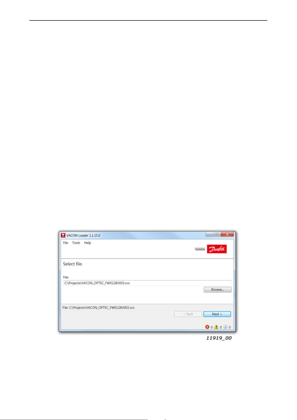
vacon • 78 Commissioning
6.6.2 OPTEC option board firmware update with VACON® Loader
You can update OPTEC EtherCAT firmware with VACON
®
Loader PC-tool. You need to have:
• PC with VACON
®
•VACON
AC drive in which OPTEC EtherCAT option board is installed
®
Loader installed
• Serial cable:
®
-VACON
VACON
serial port, then USB – RS232 converter device is needed between PC and VACON
NXP is connected to PC with RS232 serial cable which is connected from PC to
®
NXP control unit’s 9-pin DSUB connector (female). If PC does not contain RS232
®
NXP
control.
®
-VACON
The VACON
-> Downloads -> Software -> select “Drives” as Business unit. It is bundled with the VACON
100 and VACON® 20 are connected to PC with VACON® Serial Cable.
®
Loader can be downloaded from https://www.danfoss.com/en/service-and-support/
®
Live
software package. After starting the installation program, follow the on-screen instructions.
The OPTEC EtherCAT firmware can be downloaded from https://www.danfoss.com/en/serviceand-support/ -> Software -> select “Drives” as Business unit -> Fieldbus firmware.
To update the option board firmware, follow the steps below.
NOTE! With VACON
the following baud rates are supported: 9600, 19200, 38400 or 57600. With VACON
®
CON
NXP drives VACON® Loader selects a correct baud rate automatically.
®
20, the baud rate 9600 must be used. With VACON® 20 X and VACON® 20 CP,
®
100 and VA-
Step 1: Connect your PC to the controller by using the serial cable.
Then select the firmware file which you want to load to the option board and double click it. This
®
starts the VACON
Loader software. You can also start the program from the Windows Start menu.
In this case, select the firmware file using the "Browse"-button.
6
Figure 29. VACON® Loader: File selection
Local contacts: https://www.danfoss.com/en/contact-us/contacts-list/
Page 79

Commissioning vacon • 79
Step 2: Press 'next' and wait for the loader to find the network drives.
Then select a drive from the list and press 'Connect to Selected'.
Figure 30. VACON® Loader: Connecting to drive
Step 3: Select the modules to be updated, press 'next' and wait until the operation is finished.
Figure 31. VACON® Loader: Firmware loading
Local contacts: https://www.danfoss.com/en/contact-us/contacts-list/
6
Page 80

vacon • 80 Commissioning
Figure 32.VACON® Loader: Loading is finished
6.6.3 PC Tools for VACON® NXP: NCDrive
You can configure the VACON
PC-tool. You need to have:
• PC with NCDrive installed
•VACON
• In case of Serial connection:
- If PC contains RS232 serial port, then connect the serial cable from PC to VACON
trol unit’s 9-pin DSUB connector (female).
- If PC does not contain RS232 serial port, then USB – RS232 converter device is needed
between PC and VACON
• In case of Ethernet connection:
- Another option board supporting Ethernet connection, for example OPTE9 Dual Port Ethernet Option Board and an Ethernet cable connected to it or
- OPTEC EtherCAT option board with firmware V004 or later and Ethernet over EtherCAT
enabled on master PLC.
The NCDrive can be downloaded from https://www.danfoss.com/en/service-and-support/ ->
Downloads -> Software -> select “Drives” as Business unit. After starting the installation program,
follow the on-screen instructions.
®
NXP drive
®
NXP AC drive and OPTEC EtherCAT parameters with the NCDrive
®
NXP con-
®
NXP control.
6
Once the program is installed successfully, you can launch it by selecting it in the Windows Start
menu. Select Help --> Contents if you want more information about the software features.
Local contacts: https://www.danfoss.com/en/contact-us/contacts-list/
Page 81

Commissioning vacon • 81
6.6.3.1 NCDrive Serial communication settings
Connect your PC to the controller by using the USB/RS485 cable.
Select Tools -> Options… -> Communication tab. Then define settings for your USB - RS232 adapter
and press Ok.
Figure 33. NCDrive: Serial communication settings
6.6.3.2 NCDrive Ethernet communication settings
For NCDrive Ethernet connection you need to have:
• Working Ethernet connection between PC and AC drive
• NCDrive is parametrized to use Ethernet connection
See instructions from Ethernet option board manual. Option board manuals can be downloaded
from https://www.danfoss.com/en/service-and-support/ -> Documentation -> Select “Drives” as
Business unit -> Select “VACON Option Boards” as Product Series.
6.6.3.3 Connecting to NCDrive
Press the "ON-LINE" button. The NCDrive will connect to the drive and start loading parameter information.
Figure 34. NCDrive: Going online
Figure 35. NCDrive: Loading information from the drive
Local contacts: https://www.danfoss.com/en/contact-us/contacts-list/
6
Page 82

vacon • 82 Commissioning
To change the option board settings, navigate to the "M 7 Expander boards" menu and select the
slot in which OPTEC EtherCAT is connected to. It is possible to change parameters defined in
Chapter 6.1 "AC drive and OPTEC EtherCAT option board parametrization".
Figure 36. NCDrive: Parameter menu
6.6.4 PC Tools for VACON® 100 and VACON® 20: VACON® Live
You can configure the VACON
eters with the VACON
®
Live PC-tool. Also monitor values of these devices can be read with VACON®
®
100 AC drives, VACON® 20 AC drives and OPTEC EtherCAT param-
Live. You need to have:
• PC with VACON
•VACON
®
100 or VACON® 20 AC drive
®
Live installed
• In case of Serial connection:
®
-VACON
Serial Cable (USB - Serial cable) which is connected from PC to AC drive control
unit.
®
-In case of VACON
not needed in case of VACON
20 also MCA (Micro Communications Adapter) is required. This adapter is
®
20 X / CP.
• In case of Ethernet connection:
- Another option board supporting Ethernet connection, for example OPTE9 Dual Port Ethernet Option Board and an Ethernet cable connected to it or
- OPTEC EtherCAT option board with firmware V004 or later and Ethernet over EtherCAT
enabled on master PLC.
®
-In case of VACON
100 it is possible to use inbuilt Ethernet connection.
6
®
NOTE! VACON
20, VACON® 20 X and VACON® 20 Cold Plate do not support VACON® Live connec-
tion over Ethernet.
The VACON
®
Live can be downloaded from https://www.danfoss.com/en/service-and-support/ ->
Downloads -> Software -> select “Drives” as Business unit. After starting the installation program,
follow the on-screen instructions.
Once the program is installed successfully, you can launch it by selecting it in the Windows Start
menu. Select Help --> Contents if you want more information about the software features.
Local contacts: https://www.danfoss.com/en/contact-us/contacts-list/
Page 83

Commissioning vacon • 83
6.6.4.1 VACON® Live Serial communication settings
Step 1: Connect your PC to VACON® AC drive with VACON® Serial Cable.
Step 2: Start VACON
startup mode. After this the program scans compatible drives.
®
Live. When the program starts, it asks "Select startup mode". Select "Online"
Figure 37. VACON® Live: To online mode
Step 2b: If VACON® Live cannot find your AC drive then ensure that "Serial / Ethernet" or "Serial"
is selected. After that press "Scan".
Figure 38. VACON® Live: Communication settings
Local contacts: https://www.danfoss.com/en/contact-us/contacts-list/
6
Page 84

vacon • 84 Commissioning
Step 3: After successful scanning VACON® Live shows the drive in connected drives window. Select
the drive and press "Connected to Selected". After this VACON
value tree from the drive.
®
Live reads parameter and monitor
Figure 39. VACON® Live: Communication settings
6.6.4.2 VACON® Live Ethernet communication settings
For VACON® Live Ethernet connection you need to have:
• Working Ethernet connection between PC and AC drive
®
• VACON
See instructions from VACON
Ethernet option board manual. Manuals can be downloaded from https://www.danfoss.com/en/
service-and-support/ -> Documentation -> Select “Drives” as Business unit -> Select “VACON Option Boards” as Product Series.
Live is parametrized to use Ethernet connection
®
100 Modbus, PROFINET IO, Ethernet/IP, BACnet or OPTE9 Dual Port
6
Local contacts: https://www.danfoss.com/en/contact-us/contacts-list/
Page 85

Commissioning vacon • 85
6.6.4.3 OPTEC EtherCAT parameters in VACON Live
OPTEC EtherCAT parameters and monitor values can be found from "5. I/O and Hardware" menu.
With VACON
®
Live it is possible to modify OPTEC EtherCAT parameters and view monitor values.
Figure 40. VACON® Live: OPTEC EtherCAT parameters.
Local contacts: https://www.danfoss.com/en/contact-us/contacts-list/
6
Page 86

vacon • 86 EtherCAT
7. ETHERCAT
The OPTEC Option Board offers data objects through EtherCAT by the process data image and by
mailbox protocols. The supported mailbox protocols is CanOpen Over EtherCAT(CoE). The available
data objects depend on the accessing method used.
The difference between the process data image and mailbox protocols are that the mailbox transfer
is initiated only on demand and the process data image is constantly kept up-to date between the
EtherCAT Master and all EtherCAT slaves in the EtherCAT bus.
Figure 41. Communication between EtherCAT bus and VACON® drive
CONTROL BOARD
CANopen
Application
Object Dictionary
SDO
CoE CoE
Mailbox
EtherCAT Slave Controller
EtherCAT bus
Process Data
OPTION BOARD
PDO Mapping
Process Data
9421_uk
7
7.1 Data object list
Data objects from index 1000h to 1018h are CANopen DS-301 specific and descriptions can be found
from Chapter 9 "APPENDIX A: CANOPEN DS301 SPECIFIC DATA OBJECT DESCRIPTIONS". Data
objects from index 1C30h to 1C4Fh are EtherCAT sync manager specific.
Data objects from 2000h to 5EFFh are dynamically mapped, meaning that they are not defined by
the option board. These objects are defined by the EtherCAT Master ESI configuration file and vary
depending on the drive and application used. See Figure 18 for more details.
Local contacts: https://www.danfoss.com/en/contact-us/contacts-list/
Page 87

EtherCAT vacon • 87
Table 27. All data objects
Index:
Sub-index
1000 - Device type UINT32 RO
1001 - Error register UINT8 RO
1008 - Manufacturer Device Name STRING5 RO
1009 - Manufacturer Hardware Version STRING3 RO
100A - Manufacturer Software Version STRING8 RO
1018 0 Identity Object Group RO
01 Vendor ID UINT32 RO
02 Product Code UINT32 RO
03 Revision Number UINT32 RO
04 Serial Number UINT32 RO
1600 0 1st Receive PDO Mapping Group RO
01 CiA-402 Control word UINT32 RO
Name Type R/W Description
General Parameters
Receive PDO Mapping Parameters
See Chapter 9 for description
02 CiA-402 vl Target Velocity UINT32 RO
1601 0 2nd Receive PDO Mapping Group RO
01 Drive Process Data In 1 UINT32 RO
02 Drive Process Data In 2 UINT32 RO
03 Drive Process Data In 3 UINT32 RO
04 Drive Process Data In 4 UINT32 RO
1602 0 3rd Receive PDO Mapping Group RO
01 Drive Process Data In 5 UINT32 RO
02 Drive Process Data In 6 UINT32 RO
03 Drive Process Data In 7 UINT32 RO
04 Drive Process Data In 8 UINT32 RO
1603 0 4th Receive PDO Mapping Group RO
01 Drive Process Data In 9 UINT32 RO
02 Drive Process Data In 10 UINT32 RO
03 Drive Process Data In 11 UINT32 RO
04 Drive Process Data In 12 UINT32 RO
EtherCAT process data objects from
EtherCAT master to OPTEC EtherCAT
Local contacts: https://www.danfoss.com/en/contact-us/contacts-list/
7
Page 88

vacon • 88 EtherCAT
Table 27. All data objects
Index:
Sub-index
1604 0 5th Receive PDO Mapping Group RO
01 Drive Process Data In 13 UINT32 RO
02 Drive Process Data In 14 UINT32 RO
03 Drive Process Data In 15 UINT32 RO
04 Drive Process Data In 16 UINT32 RO
0 6th Receive PDO Mapping Group RO
01 Drive process data in 1, 32bit UINT32 RO
1605
1606
02 Drive process data in 2, 32bit UINT32 RO
03 Drive process data in 3, 32bit UINT32 RO
04 Drive process data in 4, 32bit UINT32 RO
0 7th Receive PDO Mapping Group RO
01 Drive process data in 5, 32bit UINT32 RO
02 Drive process data in 6, 32bit UINT32 RO
03 Drive process data in 7, 32bit UINT32 RO
04 Drive process data in 8, 32bit UINT32 RO
0 8th Receive PDO Mapping Group RO
Name Type R/W Description
EtherCAT process data objects from
EtherCAT master to OPTEC EtherCAT
01 Drive process data in 9, 32bit UINT32 RO
1607
1608
1610 0 17th Receive PDO Mapping Group RO
1A00 0 1st Transmit PDO Mapping Group RO
02 Drive process data in 10, 32bit UINT32 RO
03 Drive process data in 11, 32bit UINT32 RO
04 Drive process data in 12, 32bit UINT32 RO
0 9th Receive PDO Mapping Group RO
01 Drive process data in 13, 32bit UINT32 RO
02 Drive process data in 14, 32bit UINT32 RO
03 Drive process data in 15, 32bit UINT32 RO
04 Drive process data in 16, 32bit UINT32 RO
01 Bypass Fixed Control Word UINT32 RO
02 Bypass General Control Word UINT32 RO
03 Bypass Speed Setpoint Value UINT32 RO
Transmit PDO Mapping Parameters
01 CiA-402 Status Word UINT32 RO
02 CiA-402 vl Velocity Actual Value UINT32 RO
EtherCAT process data objects from
OPTEC EtherCAT to EtherCAT master
7
Local contacts: https://www.danfoss.com/en/contact-us/contacts-list/
Page 89

EtherCAT vacon • 89
Table 27. All data objects
Index:
Sub-index
1A01 0 2nd Transmit PDO Mapping Group RO
01 Drive Process Data out 1 UINT32 RO
02 Drive Process Data out 2 UINT32 RO
03 Drive Process Data out 3 UINT32 RO
04 Drive Process Data out 4 UINT32 RO
1A02 0 3rd Transmit PDO Mapping Group RO
01 Drive Process Data out 5 UINT32 RO
02 Drive Process Data out 6 UINT32 RO
03 Drive Process Data out 7 UINT32 RO
04 Drive Process Data out 8 UINT32 RO
1A03 0 4th Transmit PDO Mapping Group RO
01 Drive Process Data out 9 UINT32 RO
02 Drive Process Data out 10 UINT32 RO
03 Drive Process Data out 11 UINT32 RO
Name Type R/W Description
EtherCAT process data objects from
OPTEC EtherCAT to EtherCAT master
04 Drive Process Data out 12 UINT32 RO
1A04 0 5th Transmit PDO Mapping Group RO
01 Drive Process Data out 13 UINT32 RO
02 Drive Process Data out 14 UINT32 RO
03 Drive Process Data out 15 UINT32 RO
04 Drive Process Data out 16 UINT32 RO
0 6th Transmit PDO Mapping Group RO
01 Drive process data out 1, 32bit UINT32 RO
1A05
1A06
02 Drive process data out 2, 32bit UINT32 RO
03 Drive process data out 3, 32bit UINT32 RO
04 Drive process data out 4, 32bit UINT32 RO
0 7th Transmit PDO Mapping Group RO
01 Drive process data out 5, 32bit UINT32 RO
02 Drive process data out 6, 32bit UINT32 RO
03 Drive process data out 7, 32bit UINT32 RO
04 Drive process data out 8, 32bit UINT32 RO
EtherCAT process data objects from
OPTEC EtherCAT to EtherCAT master
EtherCAT process data objects from
OPTEC EtherCAT to EtherCAT master
0 8th Transmit PDO Mapping Group RO
01 Drive process data out 9, 32bit UINT32 RO
1A07
Local contacts: https://www.danfoss.com/en/contact-us/contacts-list/
02 Drive process data out 10, 32bit UINT32 RO
03 Drive process data out 11, 32bit UINT32 RO
04 Drive process data out 12, 32bit UINT32 RO
EtherCAT process data objects from
OPTEC EtherCAT to EtherCAT master
7
Page 90

vacon • 90 EtherCAT
Table 27. All data objects
Index:
Sub-index
0 9th Transmit PDO Mapping Group RO
01 Drive process data out 13, 32bit UINT32 RO
1A08
1A10 0 17th Transmit PDO Mapping Group RO
1C12 0 RxPDO assign Group RW
02 Drive process data out 14, 32bit UINT32 RO
03 Drive process data out 15, 32bit UINT32 RO
04 Drive process data out 16, 32bit UINT32 RO
01 Bypass Fixed Status Word UINT32 RO
02 Bypass General Status Word UINT32 RO
03 Bypass Speed Actual Value UINT32 RO
01 Receive PDO Mapping 1 UINT16 RW
02 Receive PDO Mapping 2 UINT16 RW
03 Receive PDO Mapping 3 UINT16 RW
04 Receive PDO Mapping 4 UINT16 RW
Name Type R/W Description
PDO Assign Parameters
EtherCAT process data objects from
OPTEC EtherCAT to EtherCAT master
EtherCAT process data objects from
OPTEC EtherCAT to EtherCAT master
Assign of EtherCAT process data objects
that are transferred from EtherCAT
master to OPTEC EtherCAT
05 Receive PDO Mapping 5 UINT16 RW
06 Receive PDO Mapping 6 UINT16 RW
1C13 0 TxPDO assign Group RW
01 Transmit PDO Mapping 1 UINT16 RW
02 Transmit PDO Mapping 2 UINT16 RW
03 Transmit PDO Mapping 3 UINT16 RW
04 Transmit PDO Mapping 4 UINT16 RW
05 Transmit PDO Mapping 5 UINT16 RW
06 Transmit PDO Mapping 6 UINT16 RW
Sync Manager Parameters
1C32 0 SM Output parameters Group RO
01 Sync mode UINT16 RW Current output sync mode
04 Sync modes supported UINT16 RO Supported output sync modes
05 Minimum cycle time UINT32 RO Minimum cycle time supported
06 Calc and copy time UINT32 RO Calculation and copy time
09 Delay time UINT32 RO Hardware delay time
Assign of EtherCAT process data objects
that are transferred from OPTEC
EtherCAT to EtherCAT master
7
0B SM-Event missed UINT16 RO SM event missed counter
0C Cycle time too small UINT16 RO Cycle time too small counter
20 Sync error BOOLEAN RO Indicates sync error
Local contacts: https://www.danfoss.com/en/contact-us/contacts-list/
Page 91

EtherCAT vacon • 91
Table 27. All data objects
Index:
Sub-index
1C33 0 SM Input parameter Group RO
01 Sync mode UINT16 RW Current input sync mode
04 Sync modes supported UINT16 RO Supported input sync modes
05 Minimum cycle time UINT32 RO Minimum cycle time supported
06 Calc and copy time UINT32 RO Calculation and copy time
09 Delay time UINT32 RO Hardware delay time
0B SM-Event missed UINT16 RO SM event missed counter
0C Cycle time too small UINT16 RO Cycle time too small counter
20 Sync error BOOLEAN RO Indicates sync error
2000 - First application specific object - -
5EFF - Last application specific object - -
Name Type R/W Description
Dynamic Manufacturer Specific Parameter Area
Static Manufacturer Specific Parameters
Chapter 7.4 "Accessing drive
parameters via CoE MailBox"
Chapter 7.4 "Accessing drive
parameters via CoE MailBox"
5FF1
0Fault history GroupRW
01 Item 1, fault code UINT16 RO Fault code of fault history item 1
02 Item 1, subcode UINT16 RO Subcode of fault history item 1
03 Item 1, seconds UINT32 RO
04 Item 1, milliseconds UINT16 RO
05 Item 2, fault code UINT16 RO Fault code of fault history item 2
06 Item 2, subcode UINT16 RO Subcode of fault history item 2
... ... As many as there are subindexes
5FF2 - Drive System Time UINT32 RW Time in Unix format
5FF3 0 Drive Information Group RO
01 Drive Serial Number STRING20 RO Serial number
02 Drive Name STRING40 RW VACON
5FF4 0 ESI File Selection Mode Group RO
Number of subindexes (4 times number
of fault history items). Cleared if 0 is
written.
Timestamp seconds of fault history item
1
Timestamp milliseconds of fault history
item 1
®
100 drive name
01 Selection Mode UINT16 RW Selected mode
02 Static Product Code UINT32 RW Static mode product code
03 Static Revision Number UINT16 RW Static mode revision number
Local contacts: https://www.danfoss.com/en/contact-us/contacts-list/
7
Page 92

vacon • 92 EtherCAT
Table 27. All data objects
Index:
Sub-index
5FF5 0 Operating Energy Group RO Access drive energy counters
01 Energy FLOAT32 RO Total energy
02 Trip Energy FLOAT32 RO Trip energy value
03 Reset Trip Energy UINT16 RW Reset Trip Energy
5FF6 0 Trip Operating Time Group RO
01 Years UINT16 RO Trip operating years
02 Days UINT16 RO Trip operating days
03 Hours UINT16 RO Trip operating hours
04 Minutes UINT16 RO Trip operating minutes
05 Seconds UINT16 RO Trip operating seconds
06 Total seconds UINT32 RO Total trip operating seconds
07 Reset Trip Operating Time UINT16 RW Reset Trip Operating Time
5FF7 0 Operating Time Group RO
01 Years UINT16 RO Operating years
Name Type R/W Description
02 Days UINT16 RO Operating days
03 Hours UINT16 RO Operating hours
04 Minutes UINT16 RO Operating minutes
05 Seconds UINT16 RO Operating seconds
06 Total seconds UINT32 RO Total operating seconds
5FF8 0 ParReadCoE Group RO Parameter channel read
01 ParReadID UINT16 RW Read ID
02 ParReadIDValue UINT32 RO Read value
03 ParReadSeqNo UINT16 RO Read sequence number
04 ParReadIDStatus INT16 RO Read status
5FF9 0 ParWriteCoE Group RO Parameter channel write
01 ParWriteID UINT16 RW Write ID
02 ParWriteIDValue UINT32 RW Write value
03 ParWriteSeqNo UINT16 RO Write sequence number
04 ParWriteIDStatus INT16 RO Write status
5FFA 0 Bypass Control Group RO
7
01 Bypass Fixed Control Word UINT16 RW Bypass mode control word
02 Bypass General Control Word UINT16 RW Application specific control word
5FFB 0 Bypass Status Group RO
01 Bypass Fixed Status Word UINT16 RO Bypass mode status word
02 Bypass General Status Word UINT16 RO Application specific status word
Local contacts: https://www.danfoss.com/en/contact-us/contacts-list/
Page 93

EtherCAT vacon • 93
Table 27. All data objects
Index:
Sub-index
5FFC - Bypass Speed Setpoint Value UINT16 RW Bypass speed control
5FFD - Bypass Speed Actual Value UINT16 RO Bypass actual speed
5FFE 0 Drive Process Data In Group RO
01 Drive Process Data In 1 UINT16 RO
02 Drive Process Data In 2 UINT16 RO
03 Drive Process Data In 3 UINT16 RO
04 Drive Process Data In 4 UINT16 RO
05 Drive Process Data In 5 UINT16 RO
06 Drive Process Data In 6 UINT16 RO
07 Drive Process Data In 7 UINT16 RO
08 Drive Process Data In 8 UINT16 RO
09 Drive Process Data In 9 UINT16 RO
10 Drive Process Data In 10 UINT16 RO
11 Drive Process Data In 11 UINT16 RO
Name Type R/W Description
Application specific process data from
EtherCAT master to OPTEC EtherCAT
12 Drive Process Data In 12 UINT16 RO
13 Drive Process Data In 13 UINT16 RO
14 Drive Process Data In 14 UINT16 RO
15 Drive Process Data In 15 UINT16 RO
16 Drive Process Data In 16 UINT16 RO
17 Drive Process Data In 1, 32bit UINT32 RO
18 Drive Process Data In 2, 32bit UINT32 RO
19 Drive Process Data In 3, 32bit UINT32 RO
20 Drive Process Data In 4, 32bit UINT32 RO
21 Drive Process Data In 5, 32bit UINT32 RO
22 Drive Process Data In 6, 32bit UINT32 RO
23 Drive Process Data In 7, 32bit UINT32 RO
24 Drive Process Data In 8, 32bit UINT32 RO
25 Drive Process Data In 9, 32bit UINT32 RO
26 Drive Process Data In 10, 32bit UINT32 RO
27 Drive Process Data In 11, 32bit UINT32 RO
32bit value of Process Data In.
Supported only by VACON
®
100.
28 Drive Process Data In 12, 32bit UINT32 RO
29 Drive Process Data In 13, 32bit UINT32 RO
30 Drive Process Data In 14, 32bit UINT32 RO
31 Drive Process Data In 15, 32bit UINT32 RO
32 Drive Process Data In 16, 32bit UINT32 RO
Local contacts: https://www.danfoss.com/en/contact-us/contacts-list/
7
Page 94

vacon • 94 EtherCAT
Table 27. All data objects
Index:
Sub-index
5FFF 0 Drive Process Data Out Group RO
01 Drive Process Data Out 1 UINT16 RO
02 Drive Process Data Out 2 UINT16 RO
03 Drive Process Data Out 3 UINT16 RO
04 Drive Process Data Out 4 UINT16 RO
05 Drive Process Data Out 5 UINT16 RO
06 Drive Process Data Out 6 UINT16 RO
07 Drive Process Data Out 7 UINT16 RO
08 Drive Process Data Out 8 UINT16 RO
09 Drive Process Data Out 9 UINT16 RO
10 Drive Process Data Out 10 UINT16 RO
11 Drive Process Data Out 11 UINT16 RO
12 Drive Process Data Out 12 UINT16 RO
13 Drive Process Data Out 13 UINT16 RO
Name Type R/W Description
Application specific process data from
OPTEC EtherCAT to EtherCAT master
14 Drive Process Data Out 14 UINT16 RO
15 Drive Process Data Out 15 UINT16 RO
16 Drive Process Data Out 16 UINT16 RO
17 Drive Process Data Out 1, 32bit UINT32 RO
18 Drive Process Data Out 2, 32bit UINT32 RO
19 Drive Process Data Out 3, 32bit UINT32 RO
20 Drive Process Data Out 4, 32bit UINT32 RO
21 Drive Process Data Out 5, 32bit UINT32 RO
22 Drive Process Data Out 6, 32bit UINT32 RO
23 Drive Process Data Out 7, 32bit UINT32 RO
24 Drive Process Data Out 8, 32bit UINT32 RO
25 Drive Process Data Out 9, 32bit UINT32 RO
26 Drive Process Data Out 10, 32bit UINT32 RO
27 Drive Process Data Out 11, 32bit UINT32 RO
28 Drive Process Data Out 12, 32bit UINT32 RO
29 Drive Process Data Out 13, 32bit UINT32 RO
32bit value of Process Data Out.
Supported only by VACON
®
100.
7
30 Drive Process Data Out 14, 32bit UINT32 RO
31 Drive Process Data Out 15, 32bit UINT32 RO
32 Drive Process Data Out 16, 32bit UINT32 RO
CiA-402 Parameters
6040 CiA 402 Control Word UINT16 RW Control CiA-402 State Machine
Local contacts: https://www.danfoss.com/en/contact-us/contacts-list/
Page 95

EtherCAT vacon • 95
Table 27. All data objects
Index:
Sub-index
6041 CiA 402 Status Word UINT16 RO Current CiA-402 state
6042 CiA 402 vl Target Velocity INT16 RW RPM-speed request
6043 - CiA 402 vl Velocity Demand INT16 RO Ramp generator output scaled into RPM
6044 - CiA 402 vl Velocity Actual INT16 RO Current RPM-speed
6046 0 CiA 402 vl Velocity Min Max Amount Group RO
01 CiA 402 vl Velocity Min Amount UINT32 RW Minimum RPM-speed
02 CiA 402 vl Velocity Max Amount UINT32 RW Maximum RPM-speed
6048 0 CiA 402 vl Velocity Acceleration Group RO Slope of the acceleration ramp
01 CiA 402 vl Velocity Delta Speed UINT32 RW
02 CiA 402 vl Velocity Delta Time UINT16 RW
6049 0 CiA 402 vl Velocity Deceleration Group RO Slope of the deceleration ramp
01 CiA 402 vl Velocity Delta Speed UINT32 RW
02 CiA 402 vl Velocity Delta Time UINT16 RW
0 CiA-402 vl Velocity Setpoint Factor Group RO
Name Type R/W Description
Adjust scaling of CiA-402 vl Target
Velocity and CiA-402 vl Velocity Actual
604B
6060 - Modes of Operation INT8 RW Select operate mode
6061 - CiA 402 Modes Of Operation Display INT8 RO Current CiA-402 operation mode
6502 CiA 402 Supported Drive Modes UINT32 RO Supported CiA-402 drive
01
02
vl Velocity Setpoint Factor
Numerator
vl Velocity Setpoint Factor
Denominator
UINT16 RO Numerator of scaling factor
UINT16 RW Denominator of scaling factor
7.2 Data Object Descriptions
This chapter explains thoroughly all the data objects mentioned in Chapter 7.1.
The table below explains for the format of the data object tables of the following chapters.
Local contacts: https://www.danfoss.com/en/contact-us/contacts-list/
7
Page 96

vacon • 96 EtherCAT
Table 28. Legend of Data Object description table
Name of the Data Object
PDO Index CoE Index Valid in Mode R/W
States the OPTEC Option
Board mode in which data
States the access right of
this data object:
• R = Data object is
Read-Only
• RW = Data object is
Writable and Readable
Process data object
index if the object is
mapped to the pro-
cess data.
CoE MailBox index
of the described
data object.
of this object is valid:
• Bypass = Data is valid
when OPTEC is in
Bypass mode
• CiA-402 = Data is valid
when OPTEC is in
CiA402 Drive Profile
Mode
7.2.1 RxPDO assign
The RxPDO assign object is used to select the process data objects that are transmitted from EtherCAT master to OPTEC EtherCAT. In OPTEC EtherCAT all these indices are fixed, meaning that process data object's internal content cannot be modified in EtherCAT bus level.
In case of CiA-402 Drive Profile mode:
• Assigning of following RxPDO objects is mandatory: 0x1600, 0x1601, 0x1602, 0x1610
• Assigning of following RxPDO objects is optional: 0x1603, 0x1604
In case of Bypass mode:
• Assigning of following RxPDO objects is mandatory: 0x1601, 0x1602, 0x1610
• Assigning of following RxPDO objects is optional: 0x1603, 0x1604
• Assigning of following RxPDO objects is not required: 0x1600
NOTE! Enabling and disabling of 0x1600 CiA-402 specific process data object changes Operation
mode of OPTEC EtherCAT. See details in Chapter 6.3.3 "Operation mode selection using PDO assignment".
Each of following RxPDOs contains four (4) process data items: 0x1601, 0x1602, 0x1603 and 0x1604.
For example, 0x01601 2nd Receive PDO Mapping contains following process data items:
• Drive Process Data In 1
• Drive Process Data In 2
• Drive Process Data In 3
• Drive Process Data In 4
All VACON
items requires Normal Extended Communication or Fast Communication support from VACON
®
AC drives supports eight (8) receive process data items. Using of 9-16 process data
®
AC drive. See details of communication modes in Chapter 14 "APPENDIX F - FIELDBUS OPTION
BOARD COMMUNICATION".
If EtherCAT master assigns 16 process data items and VACON
data items, then content of RxPDOs 9-16 is ignored in VACON
®
AC drive supports only 8 process
®
AC drive.
7
RxPDO assign descriptions
PDO Index CoE Index Valid in Mode R/W
- 1C12:0 Bypass, CiA-402 RW
Local contacts: https://www.danfoss.com/en/contact-us/contacts-list/
Page 97

EtherCAT vacon • 97
Sub-index Name Type Access Description
1C12:01 Sub-index 001 UINT16 RO Fixed, mandatory
1C12:02 Sub-index 002 UINT16 RO Fixed, mandatory
1C12:03 Sub-index 003 UINT16 RO Fixed, mandatory
1C12:04 Sub-index 004
1C12:05 Sub-index 005 UINT16 RO Fixed, optional
1C12:06 Sub-index 006 UINT16 RO Fixed, optional
UINT16 RO Fixed, mandatory in CiA-402 Drive Profile
mode, optional in Bypass mode
Local contacts: https://www.danfoss.com/en/contact-us/contacts-list/
7
Page 98

vacon • 98 EtherCAT
7.2.2 TxPDO assign
The TxPDO assign object is used to select the process data objects that are transmitted from OPTEC
EtherCAT to EtherCAT master. In OPTEC EtherCAT all these indices are fixed, meaning that process
data object's internal content cannot be modified in EtherCAT bus level.
In case of CiA-402 Drive Profile mode:
• Assigning of following TxPDO objects is mandatory: 0x1A00, 0x1A01, 0x1A02, 0x1A10
• Assigning of following TxPDO objects is optional: 0x1A03, 0x1A04
In case of Bypass mode:
• Assigning of following TxPDO objects is mandatory: 0x1A01, 0x1A02, 0x1A10
• Assigning of following TxPDO objects is optional: 0x1A03, 0x1A04
• Assigning of following TxPDO objects is not required: 0x1A00
NOTE! Enabling and disabling of 0x1A00 CiA-402 specific process data object changes Operation
mode of OPTEC EtherCAT. Please see details in chapter 6.3.3 Operation mode selection using PDO
assignment
Each of following TxPDOs contains four (4) process data items: 0x1A01, 0x1A02, 0x1A03 and 0x1A04.
For example, 0x01A01 2nd Transmit PDO Mapping contains following process data items:
• Drive Process Data Out 1
• Drive Process Data Out 2
• Drive Process Data Out 3
• Drive Process Data Out 4
All VACON
®
AC drives supports eight (8) transmit process data items. Using of 9-16 process data
items requires Normal Extended Communication or Fast Communication support from VACON
AC drive. See details of communication modes in Chapter 14 "APPENDIX F - FIELDBUS OPTION
BOARD COMMUNICATION".
If EtherCAT master assigns 16 process data items and VACON
®
AC drive supports only 8 process
data items, then content of TxPDOs 9-16 is set to zero in OPTEC EtherCAT option board.
TxPDO assign descriptions
PDO Index CoE Index Valid in Mode R/W
- 1C13:0 Bypass, CiA-402 RW
Sub-index Name Type Access Description
1C13:01 Sub-index 001 UINT16 RW Fixed, mandatory
1C13:02 Sub-index 002 UINT16 RW Fixed, mandatory
1C13:03 Sub-index 003 UINT16 RW Fixed, mandatory
1C13:04 Sub-index 004
UINT16 RW Fixed, mandatory in CiA-402 Drive Profile
mode, optional in Bypass mode
1C13:05 Sub-index 005 UINT16 RW Fixed, optional
®
7
1C13:06 Sub-index 006 UINT16 RW Fixed, optional
Local contacts: https://www.danfoss.com/en/contact-us/contacts-list/
Page 99

EtherCAT vacon • 99
7.2.3 Sync Manager
These objects are used to set the inputs and outputs of the synchronization parameters.
7.2.3.1 Sync mode
The status of the input and output parameters of the synchronization manager. To identify the current synchronization mode read the objects 0x1c32 and 0x1c33. To select the synchronization mode
write to these indexes. OPTEC V003 and earlier support only freerun mode. OPTEC V004 and later
supports SM synchronous or DC synchronous modes.
Sync mode descriptions
PDO Index CoE Index Valid in Mode R/W
- 1C32:01,
Bypass, CiA-402 RW
1C33:01
1C32:01 1C33:01 Name Description
22DC sync
Application is run synchronous to EtherCAT sync0
event based on distributed clocks unit
1 34 SM sync Application is run synchronous to bus cycle
0 0 Free run mode
The EtherCAT communication and the application
run independently of each other
Writing an unsupported value to SM sync mode produces an error. It is recommended to set the
sync mode via master PLC settings and not by writing manually Sync mode parameter.
7.2.3.2 Sync modes supported
Supported sync modes can be determined by reading the logical high (1) bits from this object.
Sync Modes Supported descriptions
PDO Index CoE Index Valid in Mode R/W
- 1C32:04,
Bypass, CiA-402 RO
1C33:04
Bit Name
Description
V004 and later V003 and earlier
15 Not in use - 14 Dynamic Cycle time Not supported Not supported
3-13 Not in use - 2 DC synchronous mode supported Supported Not supported
1 SM synchronous mode supported Supported Not supported
0 Free run mode supported Supported Supported
7.2.3.3 Other parameters
All other Sync mode input and sync mode output parameters are explained in the following table.
They are only supported by OPTEC V004 and later.
Local contacts: https://www.danfoss.com/en/contact-us/contacts-list/
7
Page 100

vacon • 100 EtherCAT
Index Name Description
05 Minimum cycle time Minimum cycle time supported by device
06 Calc and copy time Calculation and copy time of device
09 Delay time Delay time of device
11
12
32
SM-Event missed
Cycle time too small
Sync error
Increases if DC sync0 event triggers and SM event
was not detected before sync0 event
Increases if SM event occurs while handling earlier SM event
Boolean flag to indicate if SM_event missed or Cycle time too small have been detected
7.2.4 Drive System Time
Use the object to read and write drive system time. Feature is supported in VACON
VACON
®
100 product family. Time is presented as unsigned 32 bit Unix time. For example, Unix time
®
NXP and
1614179339 is 24-February-2021 15:08:59. Drive System Time can be accessed also via parameter
channel by using ID 2551. See details of parameter channel in Chapter 7.4 "Accessing drive parameters via CoE MailBox".
In VACON
time zone and setting the daylight-saving mode. If VACON
®
100 family, the default time zone is UTC. Local time can be configured by changing the
®
100 AC drive is equipped with Real-time
clock battery, then setting of the time is not necessary after power cycle.
VACON
VACON
®
NXP AC drive does not have time settings, so value written to this ID must be local time.
®
NXP system time is zero after the drive boots up. The system time is started after writing
into ID 2551.
CiA-402 Modes of operation Display descriptions
PDO Index CoE Index Valid in Mode R/W
- 5FF2 Bypass, CiA-402 RW
Bit(s) Name Description
0-31 Drive System Time Range 0…4294967295
7.2.5 Drive Information
Use the object to read information from the drive. In case of VACON
®
100 product family you can
also use this object to read and write the name of the drive.
Drive Information descriptions
PDO Index CoE Index Valid in Mode R/W
- 5FF3:0 Bypass, CiA-402 RO
7
Sub-index Name Type Access Description
5FF3:01 Drive serial number STRING20 RO The serial number of the drive
Local contacts: https://www.danfoss.com/en/contact-us/contacts-list/
 Loading...