

Page 1
User Guide
VACON® OPTE3/E5 PROFIBUS DP
Page 2

Page 3

VACON® OPTE3/E5 PROFIBUS DP
User Guide
Contents
1
Introduction 8
1.1
Purpose of the Manual 8
Additional Resources 8
1.2
Manual and Software Version 8
1.3
1.4
Type Approvals and Certications 9
1.5
Product Overview 10
1.5.1
PROFIBUS 10
1.5.2
PROFIBUS DP 10
1.5.3
Features of PROFIBUS DP–VACON® Interface 10
Technical Data 10
1.5.4
VACON® PC Tools 11
1.5.5
Symbols and Abbreviations 11
1.6
Contents
Safety 13
2
2.1
Safety Symbols 13
2.2
Danger and Warnings 13
2.3
Cautions and Notices 14
2.4
Grounding 16
3
Commissioning 18
3.1
Before Commissioning 18
3.1.1
Installing VACON® PC Tools 18
3.1.2
Downloading Fieldbus Option Firmware 18
3.2
Commissioning with VACON® PC Tools 19
3.2.1
Updating Fieldbus Firmware with VACON® Loader 19
3.2.2
Adjusting Communication Settings 20
3.2.2.1
3.2.2.2
3.2.3
Setting Drive and PROFIBUS DP Parameters 21
3.2.3.1
Adjusting Serial Communication Settings in VACON® NCDrive 20
Adjusting Serial Communication Settings in VACON® Live 20
Setting Drive and PROFIBUS DP Parameters with VACON® NCDrive 21
3.2.3.2
3.3
Replacing VACON® NXS or NXL AC Drive with VACON® 100 Family AC Drive 23
4
Control Interface and Communication 25
4.1
PROFIBUS DP Communication Overview 25
4.1.1
Determining the PROFIBUS DP Cycle Time 25
4.2
Fieldbus Option Board Communication Modes 26
4.2.1
Requirements for Communication Modes 26
Setting Drive and PROFIBUS DP Parameters with VACON® Live 22
BC346130363093EN-US-000101/DPD00997 | 3Danfoss A/S © 2020.06
Page 4

VACON® OPTE3/E5 PROFIBUS DP
User Guide
4.3
Contents
4.2.2
Fieldbus Communication Mode Features and Limitations 27
4.2.3
Normal Fieldbus Communication 28
4.2.4
Fast Fieldbus Communication 28
4.2.5
Fast Safety Fieldbus Communication 29
4.2.6
Normal Extended Mode 29
Drive Control 29
4.3.1
PROFIBUS DP Modules 29
4.3.2
Fieldbus Process Data 30
4.3.3
Bypass Operating Mode 33
4.3.3.1
4.3.3.2
4.3.3.3
4.3.4
Echo Operating Mode 41
4.3.5
PROFIdrive 4.1 Control Prole 41
Control Word Overview 33
Status Word Overview 37
Control and Status Word Monitoring Values 40
4.3.5.1
4.3.5.2
4.3.5.3
4.3.5.4
4.3.5.5
4.3.5.6
4.3.5.7
4.3.5.8
4.3.5.9
4.3.5.10
4.3.5.11
4.3.5.12
4.3.6
PROFIdrive 2.0 Control Prole 55
4.3.6.1
4.3.6.2
4.3.6.3
PROFIdrive 4.1 Prole Overview 41
PROFIdrive 4.1 State Machine 41
Standard Telegrams 43
Vendor-Specic Telegrams 45
PPO Types 48
PROFIdrive 4.1 Control Word (STW1) 50
PROFIdrive 4.1 Status Word (ZSW1) 51
Setpoint Value 52
Actual Speed Value 53
Normalization Reference Parameter 53
Shortlist of Commands to Start the Drive 53
Coding of Data Signals 54
PROFIdrive 2.0 Control Word 55
PROFIdrive 2.0 Status Word 56
State Machine for PROFIdrive 2.0 57
4.3.6.4
4.4
PROFIsafe 59
4.4.1
Introduction to PROFIsafe 59
4.4.2
PROFIdrive on PROFIsafe 60
5
Parameter Access 61
5.1
Parameter Access in PROFIdrive 4.1 61
5.1.1
Parameter Access Sequence 61
PPO Types 58
BC346130363093EN-US-000101/DPD009974 | Danfoss A/S © 2020.06
Page 5

VACON® OPTE3/E5 PROFIBUS DP
User Guide
5.1.2
Parameter Requests 61
5.1.2.1
5.1.2.2
5.1.2.3
5.1.2.4
5.1.3
Parameter Responses 64
5.1.3.1
5.1.3.2
5.1.3.3
5.1.3.4
5.1.3.5
5.1.3.6
5.1.3.7
5.1.3.8
DP-V1 Header 62
Request Header 62
Parameter Address 63
Parameter Value 63
DP-V1 Header 64
Error Response 64
PROFIdrive 4.1 Error Classes and Codes 65
PROFIdrive Parameter Access Errors 66
Response Header 67
Parameter Values 68
Parameter Description Elements 68
Identier Field 68
Contents
5.1.3.9
5.1.3.10
5.1.3.11
5.1.3.12
5.1.3.13
5.1.3.14
5.1.3.15
5.1.3.16
5.1.4
Example Requests and Responses 71
5.1.4.1
5.1.4.2
5.1.4.3
5.1.4.4
5.1.4.5
5.1.4.6
5.1.4.7
Number of Array Elements Field 69
Standardization Factor Field 69
Variable Attribute Field 69
Name Field 70
Low/High Limit Fields 70
ID Extension Field 70
Normalization Reference Parameter Field 70
Normalization Field 71
Request Parameter PNU918 Value 71
Read Response to Request Parameter PNU918 Value 72
Request All Elements of Parameter PNU964 72
Read Response to Request Parameter PNU964 73
Request the Value of Unsupported Parameter PNU900 73
Read Response to Request of Unsupported Parameter PNU900 74
Request the Value of Drive Parameter ID 103 74
5.1.4.8
5.1.4.9
5.1.4.10
5.1.4.11
5.1.4.12
5.1.5
Supported Parameters 82
5.1.6
PROFIdrive Fault Buer 86
5.1.7
Drive System Time 87
Change the Value of Drive Parameter ID 103 (Successful) 75
Change the Value of Drive Parameter ID 103 (Unsuccessful) 75
Request Multiple Values from Drive 76
Change Values of Multiple Drive Parameters (Successful) 78
Change Values of Multiple Drive Parameters (Unsuccessful) 80
BC346130363093EN-US-000101/DPD00997 | 5Danfoss A/S © 2020.06
Page 6

VACON® OPTE3/E5 PROFIBUS DP
User Guide
5.1.7.1
5.1.7.2
5.2
Parameter Access in PROFIdrive 2.0 88
5.2.1
DP-V1 with PROFIdrive 2.0 88
5.2.2
Parameter Field (PKW) in PPO Types 88
5.2.3
Example Requests and Responses 89
5.2.3.1
5.2.3.2
6
Parameters 91
6.1
PROFIBUS DP Board Parameters 91
6.1.1
Slave Address 91
6.1.2
Operate Mode 91
6.1.3
Compatib. Mode 93
6.2
Parameters Congured in PLC 94
Read Drive System Time 87
Write Drive System Time 87
Read Maximum Frequency (ID = 102) 89
Write Control Place (ID = 125) 90
Contents
6.2.1
Operate Mode 94
6.2.2
DP Mode 94
6.3
Safety Parameters 94
6.4
AC Drive Parameters 94
6.4.1
AC Drive Parameters for Fieldbus Control and Reference Selection 94
6.4.2
Fieldbus Parameters for VACON® 100 Family Standard Application 95
6.4.3
Fieldbus Parameters for VACON® 20 Standard Application 95
6.4.4
Fieldbus Parameters for VACON® 20 X Multipurpose Application 96
6.4.5
Fieldbus Parameters for VACON® NXP Multipurpose Application 96
6.5
Response to Fieldbus Fault Parameter 96
6.6
VACON® NXP System Software Parameters for Application Developers 97
6.6.1
System Software Variables for Selecting Communication Modes 97
6.6.2
System Software Variables for Monitoring Supported Communication Modes 97
6.6.3
System Software Variables for Selecting the Input Process Data Slot 98
7
Monitoring Values 99
7.1
PROFIBUS DP Board Monitoring Values 99
7.1.1
PROFIBUS DP Status 104
7.1.2
FB Protocol Status 104
7.1.3
Protocol 104
7.1.4
Baud Rate 104
7.1.5
PPO Type 104
7.1.6
Telegram Type 104
7.1.7
Safety Telegram 104
BC346130363093EN-US-000101/DPD009976 | Danfoss A/S © 2020.06
Page 7

VACON® OPTE3/E5 PROFIBUS DP
User Guide
7.1.8
Protocol CW/Fieldbus CW 105
7.1.9
Protocol SW/Fieldbus SW 105
7.1.10
Drive CW 105
7.1.11
Drive SW 105
8
Fault Tracing 106
8.1
LED Indications on PROFIBUS Option Boards 106
8.2
PROFIBUS DP Diagnosis 107
8.2.1
Standard Diagnosis 107
8.2.2
Channel-Related Diagnosis 108
8.3
Fault Handling 109
8.4
Gathering Diagnostic Data 109
8.5
Typical Fault Conditions 109
8.5.1
Source3 Fault Codes 110
Contents
BC346130363093EN-US-000101/DPD00997 | 7Danfoss A/S © 2020.06
Page 8

•
•
•
•
•
•
•
NOTE! Download the English and French product manuals with applicable safety, warning and caution information from https://
www.danfoss.com/en/service-and-support/.
REMARQUE Vous pouvez télécharger les versions anglaise et française des manuels produit contenant l'ensemble des informations de sécurité, avertissements et mises en garde applicables sur le site https://www.danfoss.com/en/service-and-support/.
Manual version
New features
Firmware
version
DPD00997B
Support for VACON® 100 INDUSTRIAL, VACON® 100 FLOW, VACON® 100 X, VACON® 20 X/CP, and VACON® 20 drives.
V004
DPD00997C
Support for new B version hardware. Firmware can also be used with older A version hardware.
Improved functionality of Control-By-PLC bit. This bit does not any more force control and reference place to eldbus. This bit is still required so that control from the eldbus is possible.
V005
Support for VACON® NXP drive.
Support for PROFIsafe when OPTE3/E5 board is used together with Advanced safety option board.
See details in 4.4 PROFIsafe.
Support for Fast Communication and 16 process data when installed to VACON® NXP drive. See
details in 4.2 Fieldbus Option Board Communication Modes.
Support for "C3 C5 Mode" compatibility mode when OPTE3/E5 is installed to VACON® NXP drive.
See details in 6.1 PROFIBUS DP Board Parameters.
Support for "NX Mode" compatibility mode when OPTE3/E5 is installed to VACON® 100 family and
VACON® 20 drives. See details in 6.1 PROFIBUS DP Board Parameters.
V006
VACON® OPTE3/E5 PROFIBUS DP
User Guide
Introduction
1 Introduction
1.1 Purpose of the Manual
The PROFIBUS DP programming guide provides information about conguring the system, controlling the drive, accessing parameters, programming, troubleshooting, and some typical application examples.
The programming guide is intended for use by qualied personnel, who are familiar with the VACON® drives, PROFIBUS technology,
and with the PC or PLC that is used as a master in the system.
Read the instructions before programming and follow the procedures in this manual.
1.2 Additional Resources
Resources available for the drive and optional equipment are:
•
VACON® RS485 CAN bus Installation Guide provides the necessary information to install the option board to the AC drive.
•
The Operating Guide of the AC drive provides the necessary information to get the drive up and running.
•
The Application Guide of the AC drive provides more details on working with parameters and many application examples.
•
VACON® OPTEA/OPTE9 Ethernet Board Programming Guide provides information on Ethernet settings.
Supplementary publications and manuals are available from drives.danfoss.com/knowledge-center/technical-documentation/.
For US and Canadian markets:
1.3 Manual and Software Version
This manual is regularly reviewed and updated. All suggestions for improvement are welcome.
The original language of this manual is English.
Table 1: Manual and Software Version
BC346130363093EN-US-000101 / DPD009978 | Danfoss A/S © | 2020.06
Page 9
•
•
•
•
•
•
•
•
•
Manual version
New features
Firmware
version
DPD00997D
Support for PPO_PROFIdrive mode which enables usage of PROFIdrive 4.1 together with PPO
types. See details in 6.1 PROFIBUS DP Board Parameters.
Support for drive fault history with time stamps. See details in 5.1.5 Supported Parameters.
Support for Drive CW and Drive SW monitor values. See details in 7.1 PROFIBUS DP Board Monitor-
ing Values.
V007
DPD00997E
PROFIsafe over PROFIBUS for VACON® NXP extended for advanced safety option boards OPTBL,
OPTBM and OPTBN in slots C and E in addition to slot D.
Maintance improvements and xes.
Conguration le updated.
The structure of the manual updated. Installation information removed (see VACON® RS485 CAN
bus Installation Guide).
V008
Telegram 140
PNU 10129
V009
089
VACON® OPTE3/E5 PROFIBUS DP
User Guide
Introduction
1.4 Type Approvals and Certications
The following list is a selection of possible type approvals and certications for Danfoss drives:
N O T I C E
The specic approvals and certication for the drive are on the nameplate of the drive. For more information, contact the local
Danfoss oce or partner.
BC346130363093EN-US-000101 / DPD00997 | 9Danfoss A/S © 2020.06
Page 10

Technical item or function
Technical data
Connections
Interface
OPTE3: Pluggable connector (5.08 mm)
OPTE5: 9-pin D-SUB connector (female)
Data transfer method
RS485, half duplex
Transfer cable
Shielded Twisted Pair
Electrical isolation
500 V DC
Communications
Drive prole
PROFIdrive
Standard Telegrams
1, 20
Vendor Telegrams
100, 101, 138, 139
Standard (Safety) Telegrams
30, 31
(1)
Vendor (Safety) Telegrams
58000
(1)
PPO types
1, 2, 3, 4, 5, 6
Baud rate
9.6 kBd to 12 MBd. Autobaud detect is always on.
Addresses
2–126
Environment
Ambient operating temperature
-10°C…50°C (For further information, see the installation manual of the AC
drive)
Storing temperature
-40°C…60°C
Humidity
<95%, no condensation, or frost allowed, non-corrosive
VACON® OPTE3/E5 PROFIBUS DP
User Guide
Introduction
1.5 Product Overview
1.5.1 PROFIBUS
PROFIBUS is an international standard for eldbus communication in automation technology (IEC 61158 and IEC 61784). The member companies of the PROFIBUS International User Community support the standard.
For information about PROFIBUS and downloads for PROFIBUS DP and the PROFIdrive prole, refer to www.probus.com.
1.5.2 PROFIBUS DP
The PROFIBUS DP protocol enables communication between PROFIBUS masters and slaves.
The master devices control the communication. The master can send data without a separate command when a token is given to
the Master. The slave devices are peripheral devices. Typical slave devices include input/output devices, valves, drives, and measuring transmitters. They do not have bus access rights and they can only acknowledge received messages or send messages to the
master when requested to do so.
VACON® AC drives can be connected to the PROFIBUS DP network using a eldbus board. The drive can then be controlled, monitored, and programmed from the Host system.
OPTE5/E3 option board also supports connection from DP Master (class 2) when DP-V1 is enabled. In this case, the master class 2
can initiate a connection, read and write parameters using the PROFIdrive Parameter Access service, and close the connection.
1.5.3 Features of PROFIBUS DP–VACON® Interface
Features of the PROFIBUS DP–VACON® interface:
•
Direct control of VACON® AC drives (for example, Run, Stop, Direction, Speed reference, Fault reset)
•
Full access to all VACON® AC drive parameters
•
Monitor VACON® AC drive status (for example, output frequency, output current, fault code)
1.5.4 Technical Data
Table 2: PROFIBUS DP Option Board Technical Data
BC346130363093EN-US-000101 / DPD0099710 | Danfoss A/S © | 2020.06
Page 11

Technical item or function
Technical data
Altitude
Maximum 1000 m
Vibration
0.5 G at 9…200 Hz
Safety
Fullls EN 50178 standard
Tool
VACON® 100 family
VACON® NXS/NXP
VACON® 20 family
VACON® Loader
Serial
(1)
Serial
(1)
Serial
(1)
VACON® Live
Serial
(1)
, Ethernet
(2)
Serial
(1)
VACON® NCIPCong
Not used with OPTE3/E5 PROFIBUS DP
VACON® NCDrive
Serial
(1)
, Ethernet
(2)
VACON® NCLoad
Not used with OPTE3/E5 PROFIBUS DP
Abbreviation
Denition
CW
Control word
DP
Distributed periphery
DU
Data unit
EEPROM
Electrical erasable programmable read-only memory
EMC
Electromagnetic compatibility
FB
Fieldbus
FDT
Field device tool
GSD
Generic Station Description
HMI
Human machine interface
VACON® OPTE3/E5 PROFIBUS DP
User Guide
1
Select only when Advanced safety option board with PROFIsafe is connected.
Introduction
1.5.5 VACON® PC Tools
With VACON® PC tools, it is possible to do following operations for OPTE3/E5 PROFIBUS DP:
•
Update rmware into OPTE3/E5 PROFIBUS DP option board (with VACON® Loader), see 3.2.1 Updating Fieldbus Firmware with
VACON® Loader
•
Set parameters for OPTE3/E5 PROFIBUS DP (with VACON® NCDrive or VACON® Live), see 3.2.3.1 Setting Drive and PROFIBUS DP
Parameters with VACON® NCDrive and 3.2.3.2 Setting Drive and PROFIBUS DP Parameters with VACON® Live
•
Read monitor values of OPTE3/E5 PROFIBUS DP (with VACON® NCDrive or VACON® Live)
For instructions on downloading and installing the tools, see 3.1.1 Installing VACON® PC Tools.
The following table describes what PC tools are supported in each AC drive type.
Table 3: The Supported PC Tools with Dierent AC Drives
1
The connection type "serial" is a direct serial connection to the AC drive.
2
The connection type "Ethernet" is an Ethernet connection, for example, VACON® 100 family built-in Ethernet interface, or a connection via OPTEA/
OPTE9 Dual Port Ethernet option board.
1.6 Symbols and Abbreviations
Table 4: Symbols and Abbreviations
BC346130363093EN-US-000101 / DPD00997 | 11Danfoss A/S © 2020.06
Page 12

Abbreviation
Denition
IND
Sub index
LED
Light emitting diode
PC
Personal computer
PDI
Process Data In
PDO
Process Data Out
PLC
Programmable logic controller
PNU
Parameter number
PPO
Process parameter object
SW
Status word
VACON® OPTE3/E5 PROFIBUS DP
User Guide
Introduction
BC346130363093EN-US-000101 / DPD0099712 | Danfoss A/S © | 2020.06
Page 13

VACON® OPTE3/E5 PROFIBUS DP
User Guide
2 Safety
2.1 Safety Symbols
The following symbols are used in this manual:
D A N G E R
Indicates a hazardous situation which, if not avoided, will result in death or serious injury.
W A R N I N G
Indicates a hazardous situation which, if not avoided, could result in death or serious injury.
C A U T I O N
Indicates a hazardous situation which, if not avoided, could result in minor or moderate injury.
N O T I C E
Indicates information considered important, but not hazard-related (for example, messages relating to property damage).
Safety
2.2 Danger and Warnings
D A N G E R
SHOCK HAZARD FROM POWER UNIT COMPONENTS
The power unit components are live when the drive is connected to mains. A contact with this voltage can lead to death or seri-
ous injury.
Do not touch the components of the power unit when the drive is connected to mains. Before connecting the drive to mains,
-
make sure that the covers of the drive are closed.
D A N G E R
SHOCK HAZARD FROM TERMINALS
The motor terminals U, V, W, the brake resistor terminals, or the DC terminals are live when the drive is connected to mains, also
when the motor does not operate. A contact with this voltage can lead to death or serious injury.
Do not touch the motor terminals U, V, W, the brake resistor terminals, or the DC terminals when the drive is connected to
-
mains. Before connecting the drive to mains, make sure that the covers of the drive are closed.
D A N G E R
SHOCK HAZARD FROM DC LINK OR EXTERNAL SOURCE
The terminal connections and the components of the drive can be live 5 minutes after the drive is disconnected from the mains
and the motor has stopped. Also the load side of the drive can generate voltage. A contact with this voltage can lead to death or
serious injury.
Before doing electrical work on the drive:
-
Disconnect the drive from the mains and make sure that the motor has stopped.
Lock out and tag out the power source to the drive.
Make sure that no external source generates unintended voltage during work.
Wait 5 minutes before opening the cabinet door or the cover of the AC drive.
Use a measuring device to make sure that there is no voltage.
BC346130363093EN-US-000101 / DPD00997 | 13Danfoss A/S © 2020.06
Page 14

VACON® OPTE3/E5 PROFIBUS DP
User Guide
Safety
W A R N I N G
SHOCK HAZARD FROM CONTROL TERMINALS
The control terminals can have a dangerous voltage also when the drive is disconnected from mains. A contact with this voltage
can lead to injury.
Make sure that there is no voltage in the control terminals before touching the control terminals.
-
W A R N I N G
ACCIDENTAL MOTOR START
When there is a power-up, a power break, or a fault reset, the motor starts immediately if the start signal is active, unless the pulse
control for Start/Stop logic is selected. If the parameters, the applications or the software change, the I/O functions (including the
start inputs) can change. If you activate the auto reset function, the motor starts automatically after an automatic fault reset. See
the Application Guide. Failure to ensure that the motor, system, and any attached equipment are ready for start can result in
personal injury or equipment damage.
Disconnect the motor from the drive if an accidental start can be dangerous. Make sure that the equipment is safe to operate
-
under any condition.
W A R N I N G
LEAKAGE CURRENT HAZARD
Leakage currents exceed 3.5 mA. Failure to ground the drive properly can result in death or serious injury.
Ensure the correct grounding of the equipment by a certied electrical installer.
-
W A R N I N G
SHOCK HAZARD FROM PE CONDUCTOR
The drive can cause a DC current in the PE conductor. Failure to use a residual current-operated protective (RCD) device Type B or
a residual current-operated monitoring (RCM) device can lead to the RCD not providing the intended protection and therefore
can result in death or serious injury.
Use a type B RCD or RCM device on the mains side of the drive.
-
2.3 Cautions and Notices
C A U T I O N
DAMAGE TO THE AC DRIVE FROM INCORRECT MEASUREMENTS
Doing measurements on the AC drive when it is connected to mains can damage the drive.
Do not do measurements when the AC drive is connected to mains.
-
C A U T I O N
DAMAGE TO THE AC DRIVE FROM INCORRECT SPARE PARTS
Using spare parts that are not from the manufacturer can damage the drive.
Do not use spare parts that are not from the manufacturer.
-
C A U T I O N
DAMAGE TO THE AC DRIVE FROM INSUFFICIENT GROUNDING
Not using a grounding conductor can damage the drive.
Make sure that the AC drive is always grounded with a grounding conductor that is connected to the grounding terminal
-
that is identied with the PE symbol.
BC346130363093EN-US-000101 / DPD0099714 | Danfoss A/S © | 2020.06
Page 15

VACON® OPTE3/E5 PROFIBUS DP
User Guide
C A U T I O N
CUT HAZARD FROM SHARP EDGES
There can be sharp edges in the AC drive that can cause cuts.
Wear protective gloves when mounting, cabling, or doing maintenance operations.
-
C A U T I O N
BURN HAZARD FROM HOT SURFACES
Touching surfaces, which are marked with the 'hot surface' sticker, can result in injury.
Do not touch surfaces which are marked with the 'hot surface' sticker.
-
N O T I C E
DAMAGE TO THE AC DRIVE FROM STATIC VOLTAGE
Some of the electronic components inside the AC drive are sensitive to ESD. Static voltage can damage the components.
Remember to use ESD protection always when working with electronic components of the AC drive. Do not touch the com-
-
ponents on the circuit boards without proper ESD protection.
Safety
N O T I C E
DAMAGE TO THE AC DRIVE FROM MOVEMENT
Movement after installation can damage the drive.
Do not move the AC drive during operation. Use a xed installation to prevent damage to the drive.
-
N O T I C E
DAMAGE TO THE AC DRIVE FROM INCORRECT EMC LEVEL
The EMC level requirements for the AC drive depend on the installation environment. An incorrect EMC level can damage the
drive.
Before connecting the AC drive to the mains, make sure that the EMC level of the AC drive is correct for the mains.
-
N O T I C E
RADIO INTERFERENCE
In a residential environment, this product can cause radio interference.
Take supplementary mitigation measures.
-
N O T I C E
MAINS DISCONNECTION DEVICE
If the AC drive is used as a part of a machine, the machine manufacturer must supply a mains disconnection device (refer to EN
60204-1).
N O T I C E
MALFUNCTION OF FAULT CURRENT PROTECTIVE SWITCHES
Because there are high capacitive currents in the AC drive, it is possible that the fault current protective switches do not operate
correctly.
BC346130363093EN-US-000101 / DPD00997 | 15Danfoss A/S © 2020.06
Page 16

Cross-sectional area of the phase conductors (S) [mm2]
The minimum cross-sectional area of the protective earthing conductor in question [mm2]
S ≤ 16
S
16 < S ≤ 35
16
35 < S
S/2
VACON® OPTE3/E5 PROFIBUS DP
User Guide
N O T I C E
VOLTAGE WITHSTAND TESTS
Doing voltage withstand tests can damage the drive.
Do not do voltage withstand tests on the AC drive. The manufacturer has already done the tests.
-
2.4 Grounding
Ground the AC drive in accordance with applicable standards and directives.
C A U T I O N
DAMAGE TO THE AC DRIVE FROM INSUFFICIENT GROUNDING
Not using a grounding conductor can damage the drive.
Make sure that the AC drive is always grounded with a grounding conductor that is connected to the grounding terminal
-
that is identied with the PE symbol.
W A R N I N G
LEAKAGE CURRENT HAZARD
Leakage currents exceed 3.5 mA. Failure to ground the drive properly can result in death or serious injury.
Ensure the correct grounding of the equipment by a certied electrical installer.
-
Safety
The standard EN 61800-5-1 tells that 1 or more of these conditions for the protective circuit must be true.
The connection must be xed.
•
The protective earthing conductor must have a cross-sectional area of minimum 10 mm2 Cu or 16 mm2 Al. OR
•
There must be an automatic disconnection of the mains, if the protective earthing conductor breaks. OR
•
There must be a terminal for a second protective earthing conductor in the same cross-sectional area as the rst protective
earthing conductor.
The values of the table are valid only if the protective earthing conductor is made of the same metal as the phase conductors. If this
is not so, the cross-sectional area of the protective earthing conductor must be determined in a manner that produces a conductance equivalent to that which results from the application of this table.
The cross-sectional area of each protective earthing conductor that is not a part of the mains cable or the cable enclosure, must be a
minimum of:
•
2.5 mm2 if there is mechanical protection, and
•
4 mm2 if there is not mechanical protection. With cord-connected equipment, make sure that the protective earthing conductor
in the cord is the last conductor to be interrupted, if the strain-relief mechanism breaks.
Obey the local regulations on the minimum size of the protective earthing conductor.
N O T I C E
MALFUNCTION OF FAULT CURRENT PROTECTIVE SWITCHES
Because there are high capacitive currents in the AC drive, it is possible that the fault current protective switches do not operate
correctly.
BC346130363093EN-US-000101 / DPD0099716 | Danfoss A/S © | 2020.06
Page 17

VACON® OPTE3/E5 PROFIBUS DP
User Guide
Safety
N O T I C E
VOLTAGE WITHSTAND TESTS
Doing voltage withstand tests can damage the drive.
Do not do voltage withstand tests on the AC drive. The manufacturer has already done the tests.
-
W A R N I N G
SHOCK HAZARD FROM PE CONDUCTOR
The drive can cause a DC current in the PE conductor. Failure to use a residual current-operated protective (RCD) device Type B or
a residual current-operated monitoring (RCM) device can lead to the RCD not providing the intended protection and therefore
can result in death or serious injury.
Use a type B RCD or RCM device on the mains side of the drive.
-
BC346130363093EN-US-000101 / DPD00997 | 17Danfoss A/S © 2020.06
Page 18

VACON® OPTE3/E5 PROFIBUS DP
User Guide
Commissioning
3 Commissioning
3.1 Before Commissioning
VACON® OPTE3/E5 PROFIBUS DP can be commissioned through the control panel of the AC drive or by using the VACON® PC tools.
Before starting the commissioning, check the following:
•
When using the control panel of the AC drive for commissioning: for instructions on how to use the control panel, see the Operating Guide for VACON® NXP products or the Application Guide for the VACON® 100 family.
•
When using VACON® PC tool for commissioning: the correct tool installed.
-
For a list of supported PC tools, see 1.5.5 VACON® PC Tools.
-
For instructions on installing the tools, see 3.1.1 Installing VACON® PC Tools.
•
VACON® AC drive in which OPTE3/E5 PROFIBUS DP option board installed. See VACON® RS485 CAN bus Installation Guide for
instructions.
•
When using serial connection:
-
VACON® NXP is connected to PC with RS232 serial cable. The cable is connected from PC to the 9-pin D-SUB connector
(female) of the VACON® NXP control unit. If PC does not contain RS232 serial port, then USB - RS232 converter device is
needed between PC and VACON® NXP control unit.
-
VACON® 100 family and VACON® 20 are connected to PC with VACON® Serial Cable.
•
When using Ethernet connection:
-
Ethernet cable which is connected to the Ethernet interface of the option board, or, in VACON® 100 family drives, of the
control board.
-
VACON® NXP requires option board supporting Ethernet communication. For example, OPTEA/OPTE9 Dual Port Ethernet
option board.
3.1.1 Installing VACON® PC Tools
Prepare for commissioning by installing the needed VACON® PC Tools.
Procedure
1.
Go to www.danfoss.com/.
2.
Select Downloads from Service and Support drop-down menu.
3.
Select Drives as business unit.
4.
Download the VACON® PC tool depending on the used AC drive.
•
VACON® 100 family AC drive: VACON® Loader and VACON® Live
•
VACON® 20 AC drive: VACON® Loader and VACON® Live
•
VACON® NXP AC drive: VACON® NCDrive and VACON® Loader
5.
Start the installation program and follow the on-screen instructions.
6.
After installation, launch VACON® PC tool from Windows Start menu.
7.
For more information about software features, go to Help drop-down menu and select Contents.
3.1.2 Downloading Fieldbus Option Firmware
Prepare for commissioning by downloading the Fieldbus Option Firmware.
Procedure
Go to
1.
2.
3.
4.
www.danfoss.com/.
Select Downloads from Service and Support drop-down menu.
Select Drives as business unit.
Download le Fieldbus rmware.
BC346130363093EN-US-000101 / DPD0099718 | Danfoss A/S © | 2020.06
Page 19
e30bh634.10
e30bh635.10
VACON® OPTE3/E5 PROFIBUS DP
User Guide
Commissioning
3.2 Commissioning with VACON® PC Tools
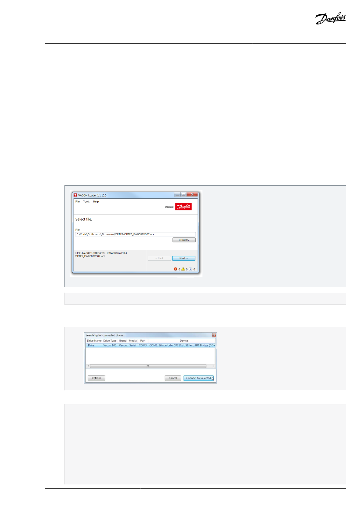
3.2.1 Updating Fieldbus Firmware with VACON® Loader
Use these instructions to upload the eldbus rmware with VACON® Loader.
NOTE! Screenshots in these instructions are examples only. The product information shown in them is dierent depending on
which option board is used.
Check the list in Before commissioning.
Adjust the baud rate if needed:
•
With VACON® 20, use the baud rate 9600.
•
With VACON® 20 X and VACON® 20 CP, the following baud rates are supported: 9600, 19200, 38400 or 57600.
•
With VACON® 100 family and VACON® NXP drives, VACON® Loader selects a correct baud rate automatically.
Procedure
1.
Connect your PC to the controller by using the serial cable.
2.
Open the File Explorer and select the rmware le to be updated to the option board and double-click it.
VACON® Loader software opens.
3.
Press Next and wait for the loader to nd the network drives.
4.
Select a drive from the list and press Connect to Selected.
5.
Select the modules to be updated, and press Next.
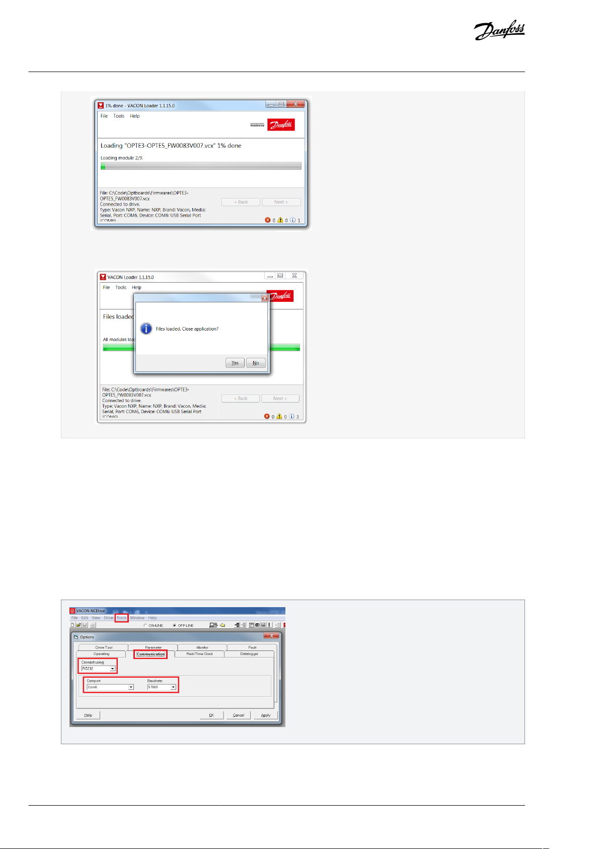
Firmware starts to load:
BC346130363093EN-US-000101 / DPD00997 | 19Danfoss A/S © 2020.06
Page 20
e30bh636.10
e30bh637.10
e30bh638.10
VACON® OPTE3/E5 PROFIBUS DP
User Guide
Commissioning
Loading is nished:
3.2.2 Adjusting Communication Settings
3.2.2.1 Adjusting Serial Communication Settings in VACON® NCDrive
Use these instructions to adjust the serial communication settings in VACON® NCDrive.
Procedure
1.
Connect your PC to the control unit by using the USB/RS232 cable.
2.
Select Tools.
3.
Select Options….
4.
Select Communication tab.
5.
Dene settings for the USB - RS232 adapter and press OK.
3.2.2.2 Adjusting Serial Communication Settings in VACON® Live
Use these instructions to adjust the serial communication settings in VACON® Live.
BC346130363093EN-US-000101 / DPD0099720 | Danfoss A/S © | 2020.06
Page 21
e30bh642.10
e30bh643.10
e30bh644.10
VACON® OPTE3/E5 PROFIBUS DP
User Guide
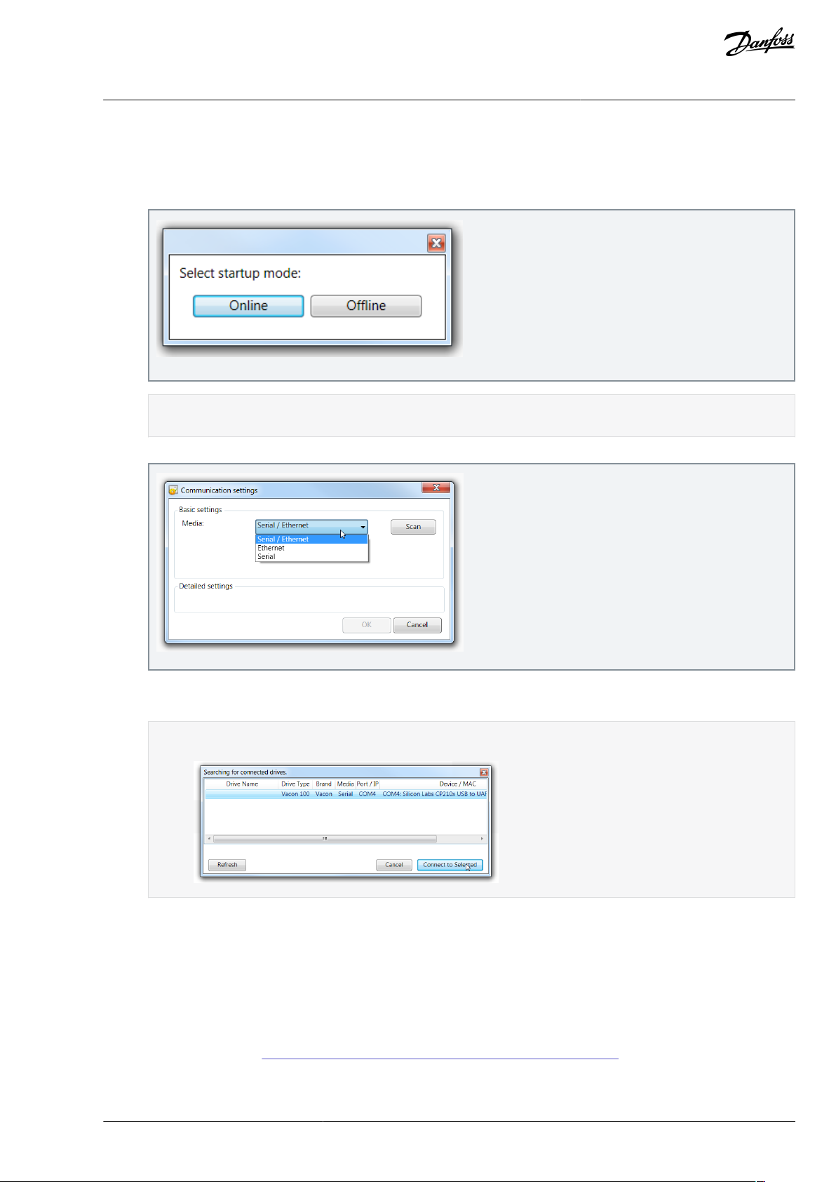
Procedure
1.
Connect the PC to VACON® AC drive with VACON® Serial Cable.
2.
Start VACON® Live.
3.
When the program starts, select Online for start-up mode.
4.
If VACON® Live cannot nd your AC drive, ensure that Serial / Ethernet or Serial is selected.
Commissioning
The program scans compatible drives. After successful scanning, VACON® Live shows the drive in connected drives
window.
5.
Press Scan.
6.
Select the drive and press Connected to Selected.
VACON® Live reads parameter and monitor value tree from the drive.
3.2.3 Setting Drive and PROFIBUS DP Parameters
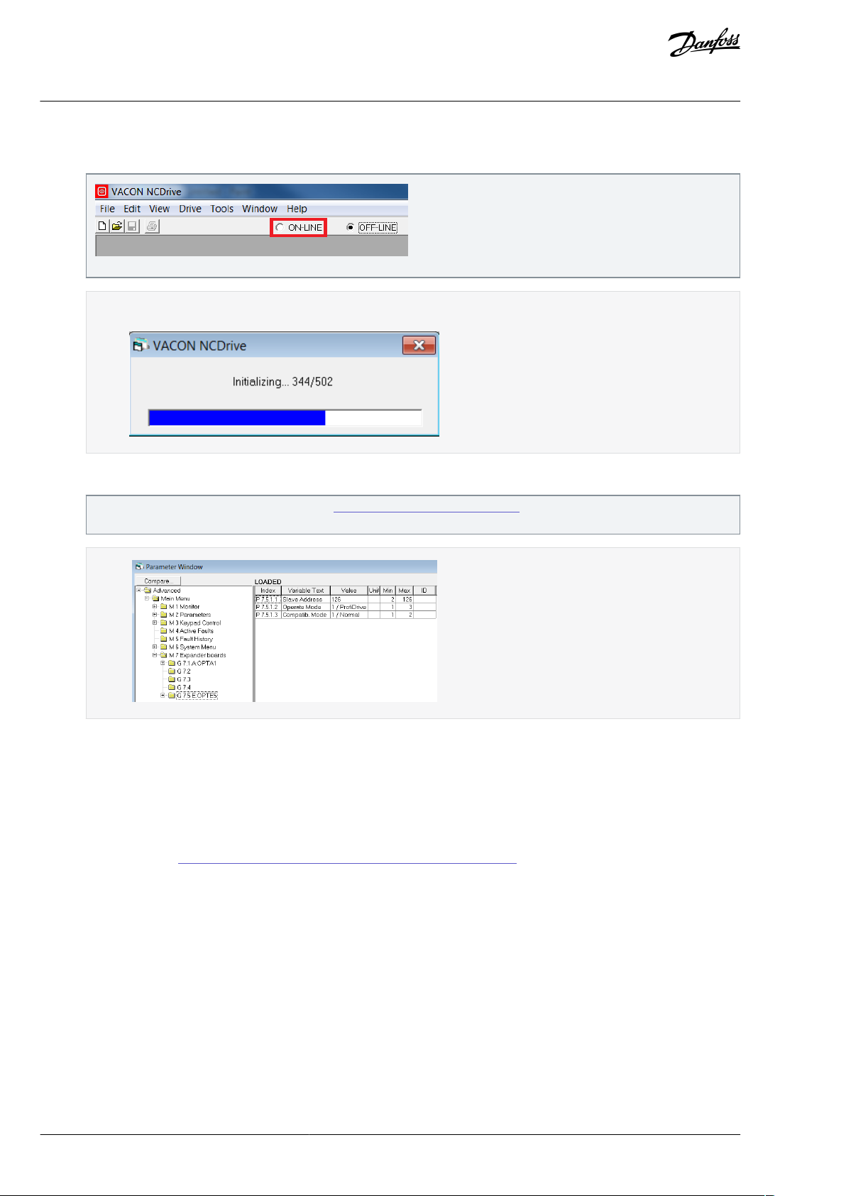
3.2.3.1 Setting Drive and PROFIBUS DP Parameters with VACON® NCDrive
Use these instructions to set the Drive and PROFIBUS DP Parameters with VACON® NCDrive.
Make sure that the communications have been adjusted. More information:
•
Serial communication:
-
VACON® NCDrive, see 3.2.2.1 Adjusting Serial Communication Settings in VACON® NCDrive
•
When using Ethernet communication, see VACON OPTEA/OPTE9 Programming Guide for instructions.
BC346130363093EN-US-000101 / DPD00997 | 21Danfoss A/S © 2020.06
Page 22
e30bh639.10
e30bh640.10
e30bh641.10
VACON® OPTE3/E5 PROFIBUS DP
User Guide
Procedure
1.
Press the ON-LINE button.
2.
To change the option board settings, navigate to the M7 Expander boards menu, and select the slot to which OPTE3/E5
PROFIBUS DP is connected.
Commissioning
The NCDrive connects to the drive and starts loading parameter information.
It is possible to change parameters dened in 6.1 PROFIBUS DP Board Parameters. Add at least the PROFIBUS slave address.
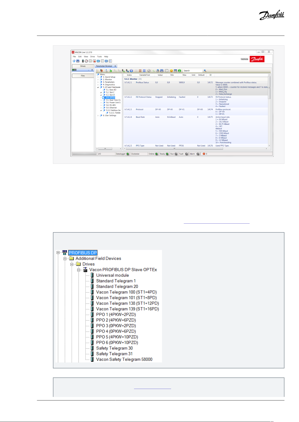
3.2.3.2 Setting Drive and PROFIBUS DP Parameters with VACON® Live
Use these instructions to nd the Drive and PROFIBUS DP Parameters with VACON® Live.
With VACON® Live, it is possible to modify OPTE3/E5 PROFIBUS DP parameters and view monitor values.
Make sure that the communications have been adjusted. More information:
•
Serial communication:
-
VACON® Live, see 3.2.2.2 Adjusting Serial Communication Settings in VACON® Live
•
When using Ethernet communication, see VACON OPTEA/OPTE9 Programming Guide for instructions.
Procedure
1.
Open VACON® Live.
2.
Navigate to 5. I/O and Hardware menu. Add at least the PROFIBUS slave address.
BC346130363093EN-US-000101 / DPD0099722 | Danfoss A/S © | 2020.06
Page 23
e30bh645.10
e30bh646.10
VACON® OPTE3/E5 PROFIBUS DP
User Guide
3.3 Replacing VACON® NXS or NXL AC Drive with VACON® 100 Family AC Drive
Make these adjustments when replacing VACON® NXS or VACON® NXL AC Drive with VACON® 100 Family AC Drive.
Commissioning
With VACON® 100 Family AC drive and OPTE3/E5, the baud rate is always automatically selected.
Procedure
1.
Take the newer GSD le into use in the PLC.
a.
Download the GSD les from http://drives.danfoss.com.
b.
If the Mode parameter is set to NX mode or C3/C5 mode (see 6.1 PROFIBUS DP Board Parameters), use the GSD le
for OPTC3/C5. This option can be used to support old installations.
By default, the OPTE3/E5 uses a dierent GSD le containing more modules than OPTC3/C5. The PPO types supported in
OPTC3/C5 (1–5) are still supported and are compatible with OPTE3/E5.
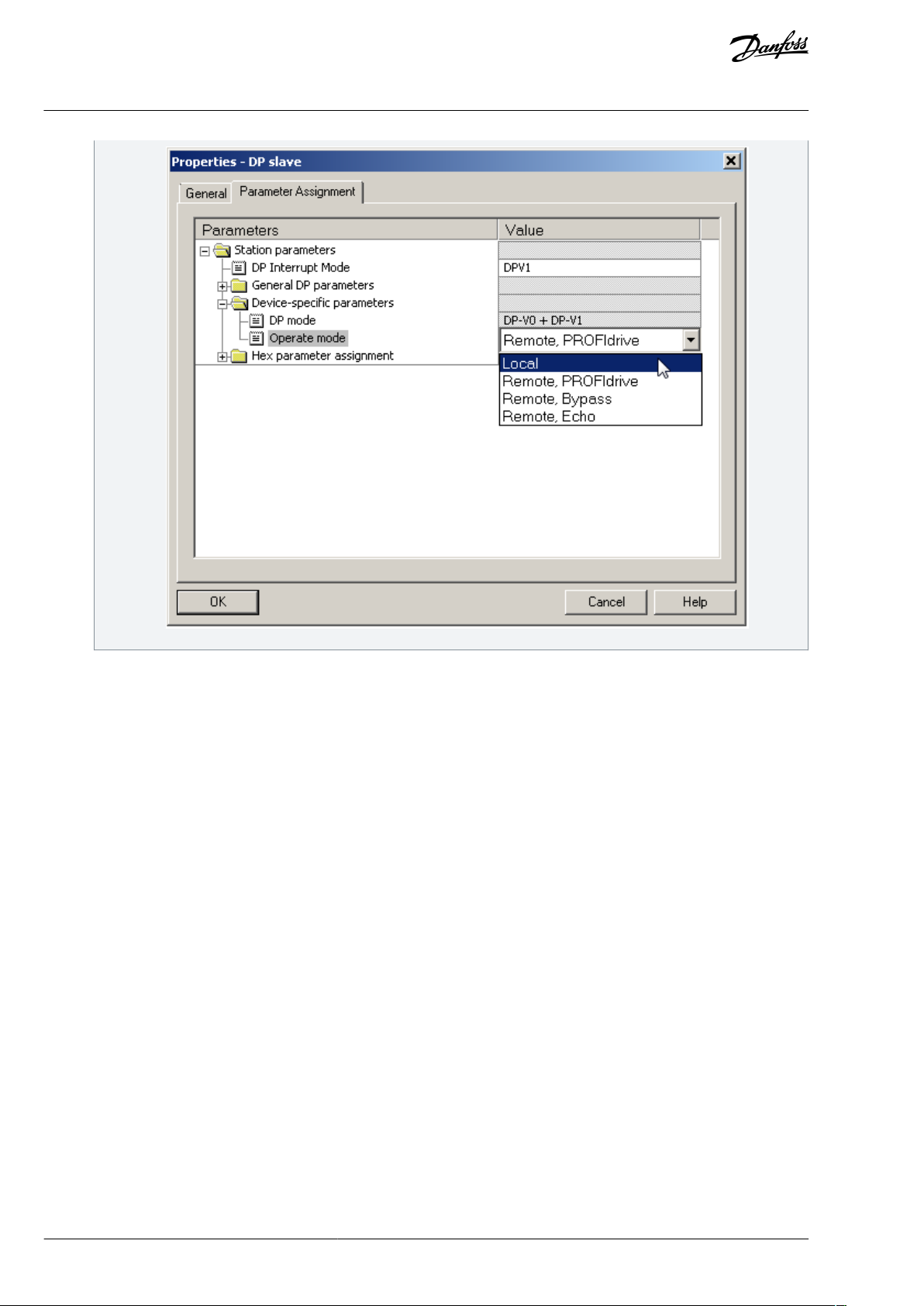
2.
To select operate mode with panel parameter, use Local.
In OPTC3/C5, the PPO type and operate mode are selected using panel parameters. In OPTE3/E5, when Local is not selected, it is possible to do it with the PLC. See 6.1.2 Operate Mode for more information.
BC346130363093EN-US-000101 / DPD00997 | 23Danfoss A/S © 2020.06
Page 24
e30bh625.10
VACON® OPTE3/E5 PROFIBUS DP
User Guide
Commissioning
3.
If needed, remove FBDIN bits used in PROFIdrive 2.0. VACON® 100 family AC drives do not support them.
BC346130363093EN-US-000101 / DPD0099724 | Danfoss A/S © | 2020.06
Page 25
PROFIBUS DP MASTER
Application
Control Word
Option Board Control Board
PDI[0]
PDI[2]
PDI[4]
PDI[10]
PDO[0]
PDO[2]
PDO[4]
PDO[10]
Speed Reference
ProcessData 1
ProcessData 2
ProcessData 1
ProcessData 2
ProcessData
Service Data
Parameter Field (4 word) Parameter Definit ons and values
Parameter Field (4 word) Variable Definit ons and values
Request
Response
Status Word
Actual Speed
..
.
...
.
...
...
e30bh618.10
VACON® OPTE3/E5 PROFIBUS DP
Control Interface and
User Guide
Communication
4 Control Interface and Communication
4.1 PROFIBUS DP Communication Overview
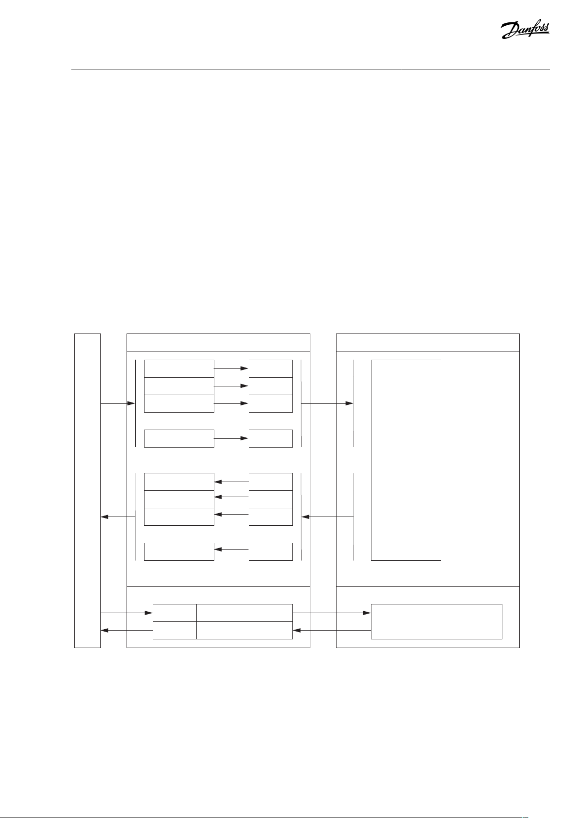
The data transfer between the PROFIBUS DP master and the slave takes place via the input/output data eld. The Master writes to
the output data of the Slave and the Slave answers by sending the contents of its input data to the Master. The contents of the
input/output data is dened in the device prole. The device prole for AC drives is PROFIdrive.
When eldbus has been selected as the active control place on the AC drive, the operation of the AC drive can be controlled from
the PROFIBUS DP Master. Regardless if the active control place is eldbus, the AC drive can be monitored and its parameters set by
the PROFIBUS DP Master.
The communication between the PROFIBUS DP board and the AC drive can be split into two types:
•
Process Data
-
Process Data In (PDI): For controlling AC drive, maximum of 18 words
-
Process Data Out (PDO): Is used for fast monitoring of the AC drive, maximum of 18 words
•
Service Data: Used for Write/Read parameters and variables. Available only when the device is congured to use PPO1, PPO2, or
PPO5. In this case, PROFIdrive 2.0 is used by the default. PROFIdrive 4.1 can be used together with PPO types by enabling
"PPO_PROFIdrive Mode" setting. See details in chapter 5.1 PROFIBUS DP board parameters.
NOTE! If Standard Telegrams are used in data exchange, Service Data is communicated using the acyclic data exchange as specied
in DP-V1 and the PROFIdrive 4.1 specication.
Illustration 1: Data Transfer between PROFIBUS DP Master and VACON® AC drive
4.1.1 Determining the PROFIBUS DP Cycle Time
The PROFIBUS DP cycle time must be determined, for example, when using PROFIsafe over PROFIBUS DP, as it must be considered
for the safety watchdog time.
The PROFIBUS DP master calculates the cycle time based on these variables:
BC346130363093EN-US-000101 / DPD00997 | 25Danfoss A/S © 2020.06
Page 26

Software or hardware
Fast/Normal Extended
Fast safe
Control Board
NXP (serial number 761 or later)
NXP (serial number 761 or later)
System Software
NXP00002V196.vcn
NXP00002V196.vcn
Applications
(1)
Multipurpose V236 or later (Normal Extended Mode)
Any
(2)
Fieldbus option rmware version
OPTE3/E5 V006 or later
OPTE3-E5_FW0083V006.vcx or later
OPTE9 V007 or later
-
OPTEA V001 or later
OPTEA V001 or later
(3)
VACON® OPTE3/E5 PROFIBUS DP
User Guide
•
Number of slaves
•
Transmission rate
•
Data volume (input and output data)
Use the PLC program to check the value.
Instructions use this setup:
•
PLC with 4 VACON® AC drives
•
congured with 16 bytes of Process Data
•
on a transmission rate of 1.5 Mbps.
NOTE! These examples do not include the eect of acyclic data exchange, alarms, or retransmissions.
Using Siemens TIA Portal V13
1.
Open Network view.
2.
Select the PROFIBUS network.
3.
Select General.
4.
Select PROFIBUS.
5.
Select Bus parameters.
6.
Select Ttr typical.
Control Interface and
Communication
The following value is shown: 3.3 ms.
Using Beckho TwinCAT System Manager V2
1.
Open I/O - Conguration.
2.
Select PROFIBUS master.
3.
Select EL6731 (in this example).
4.
Select Estimated DPCycle.
The following value is shown: 3.1 ms.
4.2 Fieldbus Option Board Communication Modes
The VACON® eldbus option boards support the following eldbus board communication modes:
Normal mode, for most commonly used setups (see
•
•
Normal extended mode, for setups that requires 16 process data items
•
Fast mode, with low latency process data (see 4.2.4 Fast Fieldbus Communication)
•
Fast safety mode with safety "black channel" (see 4.2.5 Fast Safety Fieldbus Communication)
•
Fast PROFIBUS mode. Use other modes with new installations.
NOTE! Not all boards support all modes. For details, see 4.2.1 Requirements for Communication Modes.
The fast communication modes can be enabled to get minimum communication delay between the eldbus and application.
4.2.3 Normal Fieldbus Communication)
4.2.1 Requirements for Communication Modes
Table 5: Requirements for Dierent Fieldbus Communication Modes for VACON® NXP
BC346130363093EN-US-000101 / DPD0099726 | Danfoss A/S © | 2020.06
Page 27

•
•
Software or hardware
Fast/Normal Extended
Fast safe
OPTEC V003 or later
-
OPTE6 V010 or later
-
OPTE7 V006 or later
-
Advanced safety option
-
OPTBL_FW0227V001 or later
Software
Normal Extended
System Software
INDUSTRIAL FW0072V030
FLOW FW0159V022
Fieldbus option rmware version
OPTE9: V010
OPTEA: V003
OPTE7: V006
OPTE3/OPTE5: V008
VACON® OPTE3/E5 PROFIBUS DP
Control Interface and
User Guide
1
For latest information about application support for eldbus communication modes, refer to application-specic manuals.
2
If safety option is congured to use a safety eldbus, the fast safe mode is automatically enabled regardless of used application. However, the
availability of 16 process items is limited by the application in use. Also the process data application cycle is normally set to 10 ms, instead of 1 ms for
fast application.
3
Only with Advanced Safety Option
Table 6: Requirements for Normal Extended Communication Mode for VACON® 100 Family
Communication
4.2.2 Fieldbus Communication Mode Features and Limitations
Fast mode
•
1 ms process data interval
•
Available in VACON® NXP slots D and E
-
Possible to run both slots simultaneously
-
Have similar process data latency in both slots
•
Service data latency is also reduced
-
Running multiple service data queries at high interval can cause high CPU load in VACON® NXP AC drive.
Fast safe mode
•
1 ms process data interval
•
Includes safety "black channel"
•
Activated/deactivated automatically, not available for setting
•
Safety eldbus must be activated in safety conguration
-
Advanced safety option board must be installed into slot D
-
Safety eldbus must be activated in safety conguration
16 process data items
•
16 process data items always require support from application
•
Available in Fast, Fast safe, and Normal extended mode
•
If no support is available in the application, the process data out is always '0', while incoming process data items 9–16 are discarded
BC346130363093EN-US-000101 / DPD00997 | 27Danfoss A/S © 2020.06
Page 28
Communication cycle
Update interval
IO Data
Cyclic
x ms
Acyclic
Parameters, etc.
Low
Priority
High
Priority
Software
10ms
10ms
Update
interval
5ms
Application
task
10-50ms
Process
Data
Application
task
50-500ms
Service
Data
Option Board Drive Control Board
e30bh626.10
VACON® OPTE3/E5 PROFIBUS DP
Control Interface and
User Guide
Communication
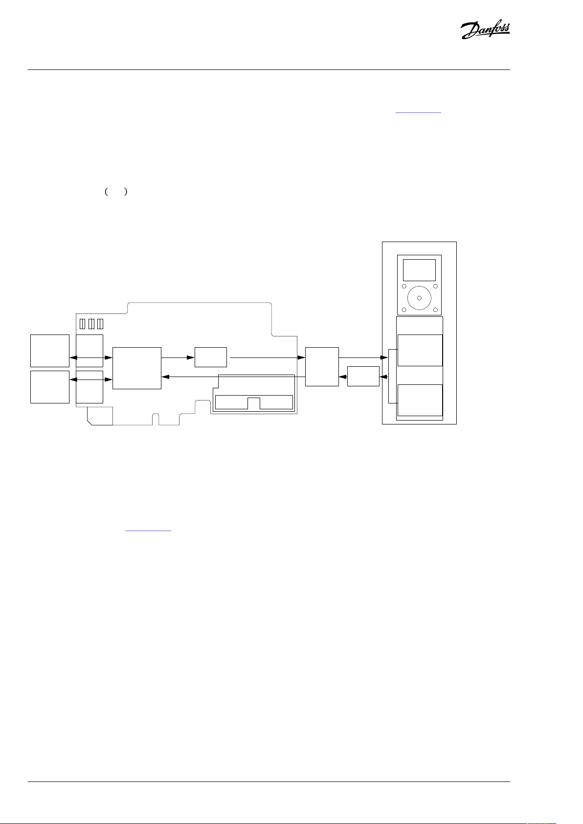
4.2.3 Normal Fieldbus Communication
The normal eldbus communication between option board and the AC drive application is shown in Illustration 2. In normal communication, both process data, and service data are transferred in succession at 5 ms interval.
Communication delay for process data can be calculated by summing all delays together:
t = t
IOdatacycle
+ t
updateinterval
+ 2 ⋅ t
communicationdelay
+ t
applicationcycle
Example: With eldbus cycle time of 4 ms and application cycle of 10 ms, the delay is:
t = 4ms + 10ms + 2 ⋅ 5 ms + 10ms = 34ms
NOTE!: This value does not include delays of the eldbus master, jitter in the process data cycle of the communication protocol or
resending due to electronic interference.
Illustration 2: Normal Fieldbus Communication
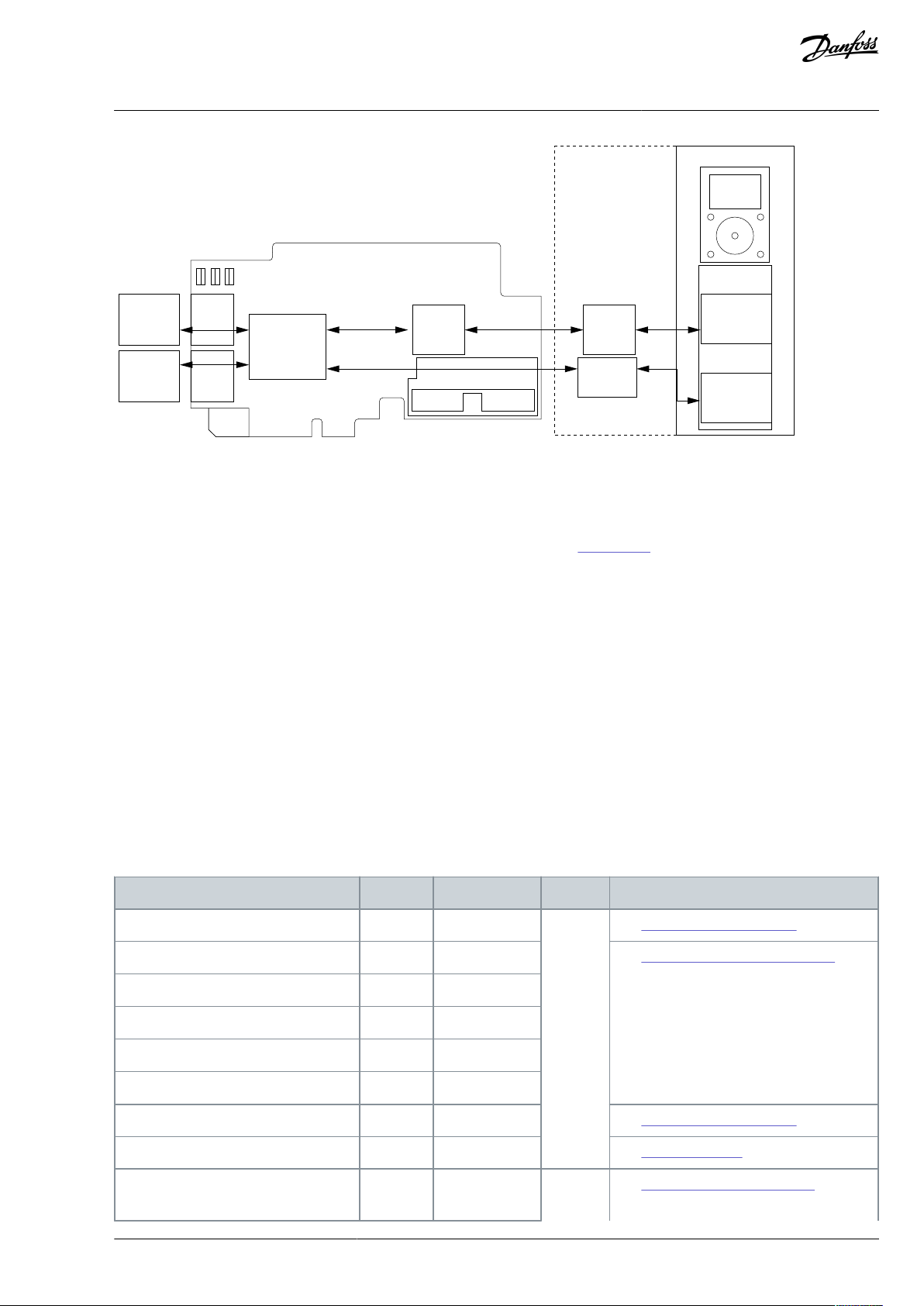
4.2.4 Fast Fieldbus Communication
The fast mode decreases the communication delay between the PLC and the AC drive application signicantly by using two communication channels separately for process and service data. The process data interval is set to 1 ms, while other data is sent acyclically. When the fast mode is activated, the application can be synchronized to run with the communication cycle. The Fast communication mode is shown in Illustration 3. This mode also includes the ability to transfer 16 process data items.
The communication delay for process data in fast communication mode is (when application task is synchronized with communication):
t = t
IOdatacycle
Example: With eldbus cycle time of 1 ms, an application cycle of 1 ms the delay is:
t = 1ms + 1+1ms = 3ms
NOTE: This value does not include delays of the eldbus master, jitter in the process data cycle of the communication protocol or
resending due to electronic interference.
+ t
updateinterval
+ t
applicationcycle
BC346130363093EN-US-000101 / DPD0099728 | Danfoss A/S © | 2020.06
Page 29
Low priority
IO Data
Cyclic
x ms
Acyclic
Parameters, etc.
Low
Priority
High
Priority
Software
Option Board Drive Control Board
1ms
1ms
Application
task
1-50ms
Process
Data
Application
task
50-500ms
Service
Data
Acyclic
Update
interval
Communication cycle
e30bh627.10
Module name
Number
Abbreviation
Type
Description
Standard Telegram 1
7
ST1
Drive
(1)
See 4.3.5.3 Standard Telegrams.
VACON® Telegram 100
8
ST1+4PD
See 4.3.5.4 Vendor-Specic Telegrams.
VACON® Telegram 101
9
ST1+8PD
VACON® Telegram 138
11
ST1+12PD
VACON® Telegram 139
12
ST1+16PD
VACON® Telegram 140
16
GCW+16PD
Standard Telegram 20
10
ST20
See 4.3.5.3 Standard Telegrams.
Parameter-Process Data Type 1…6
1...6
PPO1…PPO6
See 4.3.6.4 PPO Types.
Standard Telegram 30
13
ST30
Safety
(2)
See 4.4.2 PROFIdrive on PROFIsafe.
VACON® OPTE3/E5 PROFIBUS DP
User Guide
Illustration 3: Fast Fieldbus Communication
Control Interface and
Communication
4.2.5 Fast Safety Fieldbus Communication
The fast safety mode uses the same communication methods as in "Fast mode" (Illustration 3), but also transfers safety "black channel" data used to the advanced safety option board.
NOTE: This mode is automatically enabled, if an advanced safety option board is connected to slot D and the safety eldbus is acti-
vated and is not available for setting. This mode is also automatically turned o when the advanced safety option board is removed.
4.2.6 Normal Extended Mode
The normal extended mode uses the same communication method as in "Fast mode", but reduces the communication cycle to 10
ms. This mode can be used in applications where 16 process data items are required but the lowest possible communication delay is
not needed. It can also be used in these applications when the increased CPU load of Fast mode to VACON® NXP drives is undesirable.
NOTE! This mode can be automatically enabled in VACON® applications supporting 16 process data items.
4.3 Drive Control
4.3.1 PROFIBUS DP Modules
The OPTE3/E5 option board implements the following PROFIBUS DP modules:
Table 7: OPTE3/E5 Modules
BC346130363093EN-US-000101 / DPD00997 | 29Danfoss A/S © 2020.06
Page 30

Module name
Number
Abbreviation
Type
Description
Standard Telegram 31
14
ST31
VACON® Telegram 58000
15
ST58000
Slot 1
Slot 2: Empty
Slot 2: ST1(+PD)
Slot 2: ST20
Slot 2:PPO1...6
Empty
-
allowed
allowed
allowed
ST1(+PD)
allowed
---
ST20
allowed
---
ST30, 31
-
allowed
--ST58000
-
allowed
--PPO1...6
allowed
---
VACON® OPTE3/E5 PROFIBUS DP
User Guide
1
Drive module rules:
•
Only 1 drive module is allowed.
•
Always congure 1 drive module.
2
Safety module rules:
•
If a safety module is congured, it must always be in slot 1.
•
Only 1 safety module is allowed.
•
ST20 and PPO1...6 is not allowed with safety modules.
•
In the Advanced Safety option board, select the same safety module as congured.
The supported module combinations are described in
Table 8: Supported Module Combinations
Table 8.
Control Interface and
Communication
An invalid module conguration causes a diagnostic conguration fault. As a result, the device returns to parameterization state and
does not start the data exchange with PROFIBUS DP master.
If there is a safety module fault, a channel-related diagnosis (see 8.2.2 Channel-Related Diagnosis) is activated to notify the master of
a problem with the safety module. The data exchange is started with PROFIBUS DP master.
4.3.2 Fieldbus Process Data
The process data items are directly sent unmodied from eldbus to the application. Therefore the process data mapping and usage
must be congured in application. For the latest information, see the application-specic manual.
Fieldbus process data items can be used to write and read variables quickly and periodically to/from VACON® AC drives. Incoming
process data can be used for multiple dierent purposes (for example, torque reference), and outgoing process data can be used for
information about the state of the AC drive.
For fast access to any VACON® AC drive application ID over any eldbus, generic Process Data Out parameters are dened. The content of the process data items is selected with the FB DataOut Selection parameters. Writing any application ID number to these
parameters then maps the data value of that application ID to be sent in the corresponding Process Data Out variable.
The eldbus data-mapping (FB DataOut x Sel) aects the data of the corresponding Process Data Out variable (see Illustration 4). By
writing ID value 1 to FB DataOut1 Selection (ID 852), the value of ID 1 (Output Frequency) is sent in Process Data Out 1. The value is
always raw value in process data out, so for example, 16.43 Hz has value 1643. The scaling of the parameters can be checked from
application manuals.
The status word and actual speed values cannot be changed. However, if a prole is used, the values sent by the eldbus protocol
can dier. In Bypass mode, these values are given as is.
BC346130363093EN-US-000101 / DPD0099730 | Danfoss A/S © | 2020.06
Page 31

# Value
1 1
2 2
3 3
4 4
5 5
6 6
7 7
8 37
Fieldbus DataMap
ID Value
1 Output Frequency
2 Motor Speed
3 Motor Current
4 Motor Torque
5 Motor Power
6 Motor Voltage
7 DC-link Voltage
... ...
Vacon® ID’s
Value
16.43 Hz
486 RPM
0.12 A
4.9%
1.6%
80.2 V
332 V
37 LastActiveFaultCode
172 Rem Control Place
600 Control Mode
852 FB DataOut 1 Sel
... ...
859 FB DataOut 8 Sel
... ...
864 FB Speed Word
0
0=I/O Control
0=I/O Frequency Ctrl
Item
Process Data Out 1
Process Data Out 2
Process Data Out 3
Process Data Out 4
Process Data Out 5
Process Data Out 6
Process Data Out 7
Process Data Out 8
Fieldbus ProcessData
Value
1643
486
12
49
16
802
332
Fixed Status Word
General Status Word
Actual Speed
0x0023
0
0x2000
3284
1
...
37
0x20000023
865 FB Speed Actual
...
...
32.84%
e30bh647.10
Parameter name
ID
Index in panel tree
for VACON® 100
family
Index in panel tree for
VACON® NXP Multipurpose application
(1)
Index in panel
tree for VACON
®
20
Index in panel tree
for VACON® 20
X/CP
FB DataOut 1 Selection
852
P3.6.1
P2.13.3
P10.1
P11.1
FB DataOut 2 Selection
853
P3.6.2
P2.13.4
P10.2
P11.2
...
...
...
...
...
...
FB DataOut 8 Selection
859
P3.6.8
P2.13.10
P10.8
P11.8
FB DataOut 9 Selection
(2)
(2)-(2)
--FB DataOut 10 Selection
(2)
(2)-(2)
--...
...-...--
FB DataOut 16 Selection
(2)
(2)-(2)
-
-
PD
Mapped Application Data
ID
Unit
Scale
1
Output Frequency
1Hz0.01 Hz
2
Motor Speed
2
RPM
1 RPM
3
Motor Current
3AVaries
(1)
4
Motor Torque
4%0.1%
VACON® OPTE3/E5 PROFIBUS DP
User Guide
Control Interface and
Communication
Illustration 4: Fieldbus Data Mapping
Table 9: Fieldbus Process Data Selection Indexes in Panel Tree for VACON® AC drives
1
For other applications, see the application manuals.
2
Supported in VACON® NXP when Fast mode or Normal extended mode is enabled. See details in
and 6.6 VACON® NXP System Software Parameters for Application Developers.
Table 10: Default Process Data Mapping for VACON® 100 Family
4.2 Fieldbus Option Board Communication Modes
BC346130363093EN-US-000101 / DPD00997 | 31Danfoss A/S © 2020.06
Page 32

PD
Mapped Application Data
ID
Unit
Scale
5
Motor Power
5%0.1%6Motor Voltage
6V0.1 V7DC-link voltage
7V1 V8Last Active Fault Code
37--
PD
Mapped Application Data
ID
Unit
Scale
1
Output Frequency
1Hz0.01 Hz
2
Motor Speed
2
RPM
1 RPM
3
Motor Current
45A0.1 A4Motor Torque
4%0.1%5Motor Power
5%0.1%6Motor Voltage
6V0.1 V7DC-link voltage
7V1 V8Last Active Fault Code
37--
PD
Mapped Application Data
ID
Unit
Scale
1
Output Frequency
1Hz0.01 Hz
2
Motor Speed
2
RPM
1 RPM
3
Motor Current
3AVaries
(1)
4
Motor Torque
4%0.1%5Motor Power
5%0.1%6Motor Voltage
6V0.1 V7DC-link voltage
7V1 V8Last Active Fault Code
37--
PD
Mapped Application Data
ID
Unit
Scale
1
Frequency Reference
25Hz0.01 Hz
2
Output Reference
1Hz0.01 Hz
3
Motor Speed
2
RPM
1 RPM
4
Motor Voltage
6V0.1 V
VACON® OPTE3/E5 PROFIBUS DP
User Guide
1
Scaling is based on drive nominal power, see Table 14.
Table 11: Default Process Data Mapping for VACON® NXP Multipurpose Application
Control Interface and
Communication
Table 12: Default Process Data Mapping for VACON® 20 X/CP
1
Scaling is based on drive nominal power, see Table 14.
Table 13: Default Process Data Mapping for VACON® 20
BC346130363093EN-US-000101 / DPD0099732 | Danfoss A/S © | 2020.06
Page 33

PD
Mapped Application Data
ID
Unit
Scale
5
Motor Torque
4%0.1%6Motor Current
3AVaries
(1)
7
Motor Power
5%0.1%8DC-link voltage
7V1 V
Nominal power
Current scale
< 5 kW
0.01 A
5–100 kW
0.1 A
> 100 kW
1 A
Setpoint value
Speed
Direction of rotation
Description of command
0x0000 (0d)
0.00%
N/A
Minimum Frequency
0x2710 (+10000d)
+100.00%
Control word dep.
Full speed
Actual value
Speed
Direction of rotation
Description of value
0x0000 (0d)
0.00%
N/A
At Minimum Frequency
0x2710 (+10000d)
+100.00%
FORWARD
Full speed
VACON® OPTE3/E5 PROFIBUS DP
User Guide
1
Scaling is based on drive nominal power, see Table 14.
Table 14: Current Scaling Based on Nominal Power
Control Interface and
Communication
4.3.3 Bypass Operating Mode
In the Bypass operating mode, the control word, and status word elds in Process Data do not use the PROFIdrive bit denitions.
Instead, the internal control and status word bit denitions are used. These denitions can dier depending on the used application.
Operate mode can be set either on the control panel (see
For the control and status word denitions in the standard applications, see the following topics:
•
4.3.3.1 Control Word Overview
•
4.3.3.2 Status Word Overview
For latest information and special applications, see the application-specic manual.
Bypass Setpoint and Actual Value
In the Bypass operating mode, the valid ranges for setpoint and actual values is 0…10000d, which corresponds to 0.00% to
100.00%. The scale of the setpoint value is 0.01%. In this case, the value 0% corresponds to the parameterized Minimum Frequency
in the drive, while 100% corresponds to Maximum Frequency.
The desired direction of rotation is announced using bit 1 in the control word, whereas bit 2 in the status word indicates the actual
direction.
Table 15: Setpoint Value with Operate Mode "Bypass"
Table 16: Actual Speed Value with Operate Mode "Bypass" or "Echo"
6.1.2 Operate Mode) or in the PLC (see 6.2.1 Operate Mode).
4.3.3.1 Control Word Overview
The VACON® Control Word is composed of 32 bits. This control data is split into two words: FBFixedControlWord consist of the rst
16 bits and FBGeneralControlWord consist of the remaining 16 bits.
While functionality of the FBFixedControlWord is xed in VACON® standard applications, functionality of the FBGeneralControlWord
is application-specic and can vary even in VACON® standard applications.
FBFixedControlWord bit denitions are described in the tables:
BC346130363093EN-US-000101 / DPD00997 | 33Danfoss A/S © 2020.06
Page 34

Bit
Function
Value
Description
0
Start/Stop
0
Stop request from eldbus
1
Run request from eldbus
1
Direction
0
Requested direction is "FORWARD"
1
Requested direction is "REVERSE"
2
Fault reset
0
No action
1
Rising edge (0-->1) resets active faults, alarms, and info
3
Stop mode 1
0
Stop mode is unmodied
1
Stop mode is overridden to "Ramping"
4
Stop mode 2
0
Normal deceleration ramp time
1
Deceleration ramp is switched to shorter than normal
5
Quick ramp time
0
Normal deceleration ramp time
1
Deceleration ramp is switched to shorter than normal
6
Freeze setpoint
0
Changes in the setpoint value from eldbus (FB Speed Reference) are taken into
use by the application
1
Changes in the setpoint value from eldbus (FB Speed Reference) are not taken
into use by the application
7
Setpoint to Zero
0
The setpoint value from eldbus is taken from FB Speed Reference
1
The setpoint value from eldbus is changed to 0
8
Request Fieldbus Control
0
Control Place is as parameterized in the drive (unchanged)
1
Control Place is overridden to Fieldbus Control
9
Request Fieldbus Reference
0
Source of the setpoint value is as parameterized in the drive (unchanged)
1
Source of the setpoint value is overridden to Fieldbus
10
Jogging 1
0
No action
1
Jogging request with jogging reference 1
11
Jogging 2
0
No action
1
Jogging request with jogging reference 2
12
Quick stop
0
No action
1
Drive executes quick stop/emergency stop
VACON® OPTE3/E5 PROFIBUS DP
User Guide
•
VACON® 100 Family: Table 17
•
VACON® NXP: Table 18
•
VACON® 20: Table 19
•
VACON® 20 X/CP: Table 20
.
Set all unused bits to zero.
Table 17: Denition of FBFixedControlWord in VACON® 100 Family
Control Interface and
Communication
BC346130363093EN-US-000101 / DPD0099734 | Danfoss A/S © | 2020.06
Page 35

Bit
Function
Value
Description
13–15
Reserved
-
-
Bit
Function
Value
Description
0
Start/Stop
0
Stop request from eldbus
1
Run request from eldbus
1
Direction
0
Requested direction is "FORWARD"
1
Requested direction is "REVERSE"
2
Fault reset
0
No action
1
Rising edge (0-->1) resets active faults, alarms, and info
3
Fieldbus DIN 1
0
Fieldbus DIN 1 o
1
Fieldbus DIN 1 on
4
Fieldbus DIN 2
0
Fieldbus DIN 2 o
1
Fieldbus DIN 2 on
5
Fieldbus DIN 3
0
Fieldbus DIN 3 o
1
Fieldbus DIN 3 on
6
Fieldbus DIN 4
0
Fieldbus DIN 4 o
1
Fieldbus DIN 4 on
7
Fieldbus DIN 5
0
Fieldbus DIN 5 o
1
Fieldbus DIN 5 on
8
Request Fieldbus Control
0
Control Place is as parameterized in the drive (unchanged)
1
Control Place is overridden to Fieldbus Control
9
Request Fieldbus Reference
0
Source of the setpoint value is as parameterized in the drive (unchanged)
1
Source of the setpoint value is overridden to Fieldbus
10
Not supported
--11
Not supported
--12
Not supported
--13–15
Reserved
-
-
Bit
Function
Value
Description
0
Start/Stop
0
Stop request from eldbus
1
Run request from eldbus
1
Direction
0
Requested direction is "FORWARD"
VACON® OPTE3/E5 PROFIBUS DP
User Guide
Table 18: Denition of FBFixedControlWord in VACON® NXP
Control Interface and
Communication
Table 19: Denition of FBFixedControlWord in VACON® 20
BC346130363093EN-US-000101 / DPD00997 | 35Danfoss A/S © 2020.06
Page 36

Bit
Function
Value
Description
1
Requested direction is "REVERSE"
2
Fault reset
0
No action
1
Rising edge (0-->1) resets active faults, alarms, and info
3
Not supported
--4
Not supported
-
-
5
Quick ramp time
0
Normal deceleration ramp time
1
Deceleration ramp is switched to shorter than normal
6
Not supported
--7
Not supported
--8
Not supported
--9
Not supported
--10
Not supported
--11
Not supported
--12
Not supported
--13–15
Reserved
-
-
Bit
Function
Value
Description
0
Start/Stop
0
Stop request from eldbus
1
Run request from eldbus
1
Direction
0
Requested direction is "FORWARD"
1
Requested direction is "REVERSE"
2
Fault reset
0
No action
1
Rising edge (0-->1) resets active faults, alarms, and info
3
Stop mode 1
0
Stop mode is unmodied
1
Stop mode is overridden to "Ramping"
4
Stop mode 2
0
Normal deceleration ramp time
1
Deceleration ramp is switched to shorter than normal
5
Quick ramp time
0
Normal deceleration ramp time
1
Deceleration ramp is switched to shorter than normal
6
Freeze setpoint
0
Changes in the setpoint value from eldbus (FB Speed Reference) are taken into
use by the application
1
Changes in the setpoint value from eldbus (FB Speed Reference) are not taken
into use by the application
VACON® OPTE3/E5 PROFIBUS DP
User Guide
Control Interface and
Communication
Table 20: Denition of FBFixedControlWord in VACON® 20 X/CP
BC346130363093EN-US-000101 / DPD0099736 | Danfoss A/S © | 2020.06
Page 37

Bit
Function
Value
Description
7
Setpoint to Zero
0
The setpoint value from eldbus is taken from FB Speed Reference
1
The setpoint value from eldbus is changed to 0
8
Request Fieldbus Control
0
Control Place is as parameterized in the drive (unchanged)
1
Control Place is overridden to Fieldbus Control
9
Request Fieldbus Reference
0
Source of the setpoint value is as parameterized in the drive (unchanged)
1
Source of the setpoint value is overridden to Fieldbus
10
Not supported
--11
Not supported
-
-
12
Quick stop
0
No action
1
Drive executes quick stop/emergency stop
13–15
Reserved
-
-
Bit
Function
Value
Description
0
Ready
0
Drive is not ready
1
Drive is ready to run
1
Run
0
Motor is not running
1
Motor is running
2
Direction
0
Motor is running clockwise
1
Motor is running counterclockwise
3
Fault
(1)
0
No fault active
1
Drive has an active fault
4
Alarm
(1)
0
No alarm active
1
Drive has an active alarm
5
At reference
0
Motor is not running at reference speed
1
Motor is running at reference speed
VACON® OPTE3/E5 PROFIBUS DP
User Guide
Control Interface and
Communication
4.3.3.2 Status Word Overview
The VACON® Status Word is composed of 32 bits. This status data is split into two words: FBFixedStatusWord consist of the rst 16
bits and FBGeneralStatusWord consist of the remaining 16 bits.
While functionality of the FBFixedStatusWord is xed in VACON® standard applications, functionality of the FBGeneralStatusWord is
application-specic and can vary even in VACON® standard applications.
FBFixedStatusWord bit denitions are described in the tables. Unused bits are set to zero.
•
VACON® 100 Family: Table 21
•
VACON® NXP: Table 22
•
VACON® 20: Table 23
•
VACON® 20 X/CP: Table 24
Table 21: Denition of FBFixedStatusWord for VACON® 100 Family
BC346130363093EN-US-000101 / DPD00997 | 37Danfoss A/S © 2020.06
Page 38

Bit
Function
Value
Description
6
Zero speed
0
Motor is not at zero speed
1
Motor is running at zero speed
7
Flux ready
0
Motor is not magnetized
1
Motor is magnetized
8
Info
(1)
0
No info active
1
Drive has an active info
9–15
Reserved
-
-
Bit
Function
Value
Description
0
Ready
0
Drive is not ready
1
Drive is ready to run
1
Run
0
Motor is not running
1
Motor is running
2
Direction
0
Motor is running clockwise
1
Motor is running counterclockwise
3
Fault
(1)
0
No fault active
1
Drive has an active fault
4
Alarm
(1)
0
No alarm active
1
Drive has an active alarm
5
At reference
0
Motor is not running at reference speed
1
Motor is running at reference speed
6
Zero speed
0
Motor is not at zero speed
1
Motor is running at zero speed
7
Flux ready
0
Motor is not magnetized
1
Motor is magnetized
8
Not supported
--9–15
Reserved
-
-
VACON® OPTE3/E5 PROFIBUS DP
User Guide
1
Drive faults have three levels: fault, alarm, and info. Bits 3, 4, and 8 are set to 1 when given fault type is activated.
NOTE! In VACON® NXP series AC drives, the FBFixedStatusWord comes from rmware variable "MCStatus".
Table 22: Denition of FBFixedStatusWord for VACON® NXP
Control Interface and
Communication
1
Drive faults have three levels: fault, alarm, and info. Bits 3 and 4 are set to 1 when given fault type is activated.
BC346130363093EN-US-000101 / DPD0099738 | Danfoss A/S © | 2020.06
Page 39

Bit
Function
Value
Description
0
Ready
0
Drive is not ready
1
Drive is ready to run
1
Run
0
Motor is not running
1
Motor is running
2
Direction
0
Motor is running clockwise
1
Motor is running counterclockwise
3
Fault
(1)
0
No fault active
1
Drive has an active fault
4
Alarm
(1)
0
No alarm active
1
Drive has an active alarm
5
At reference
0
Motor is not running at reference speed
1
Motor is running at reference speed
6
Not supported
--7
Not supported
--8
Not supported
--9–15
Reserved
-
-
Bit
Function
Value
Description
0
Ready
0
Drive is not ready
1
Drive is ready to run
1
Run
0
Motor is not running
1
Motor is running
2
Direction
0
Motor is running clockwise
1
Motor is running counterclockwise
3
Fault
(1)
0
No fault active
1
Drive has an active fault
4
Alarm
(1)
0
No alarm active
1
Drive has an active alarm
5
At reference
0
Motor is not running at reference speed
1
Motor is running at reference speed
VACON® OPTE3/E5 PROFIBUS DP
User Guide
Table 23: Denition of FBFixedStatusWord for VACON® 20
Control Interface and
Communication
1
Drive faults have three levels: fault, alarm, and info. Bits 3 and 4 are set to 1 when given fault type is activated.
Table 24: Denition of FBFixedStatusWord for VACON® 20 X/CP
BC346130363093EN-US-000101 / DPD00997 | 39Danfoss A/S © 2020.06
Page 40

Bit
Function
Value
Description
6
Zero speed
0
Motor is not at zero speed
1
Motor is running at zero speed
7
Not supported
--8
Not supported
--9–15
Reserved
-
-
Signal
Index in panel tree
VACON® Live Monitoring Values
FBFixedControlWord
V2.12.1 (Low Word)
FB Control Word (Low Word)
FBGeneralControlWord
V2.12.1 (High Word)
FB Control Word (High Word)
FBFixedStatusWord
V2.12.11 (Low Word)
FB Status Word (Low Word)
FBGeneralStatusWord
V2.12.11 (Low Word)
FB Status Word (High Word)
Signal
Index in panel tree
VACON® NCDrive Monitoring Values
FBFixedControlWord
V1.24.1
(1)
FBFixedControlWord
FBGeneralControlWord
-
FBGeneralControlWord
FBFixedStatusWord
V1.24.16
(1)
MCStatus
FBGeneralStatusWord
V1.24.3
(1)
FBGeneralStatusWord
Signal
Index in panel tree for VACON®20
VACON® Live Monitoring Values
FBFixedControlWord
--FBGeneralControlWord
--FBFixedStatusWord
V3.1
Drive status word
VACON® OPTE3/E5 PROFIBUS DP
Control Interface and
User Guide
1
Drive faults have three levels: fault, alarm, and info. Bits 3 and 4 are set to 1 when given fault type is activated.
Communication
4.3.3.3 Control and Status Word Monitoring Values
The following tables describe how the control/status words can be read from dierent drives via panel or PC-tool.
•
VACON® 100 Family: Table 25
•
VACON® NXP: Table 27
•
VACON®20 Family: Table 27
For VACON® 100 family, VACON® 20, and VACON® 20X/CP, VACON® Live PC tool is used for accessing drive parameters. VACON
NCDrive PC tool is used with VACON® NXP drive.
To monitor in VACON® NCDrive, do the following settings:
•
View --> Monitoring
•
Type: Firmware
®
Table 25: Monitoring of Control and Status Words for VACON® 100 Family
Table 26: Monitoring of Control and Status Words for VACON® NXP
1
Advanced Application only
Table 27: Monitoring of Control and Status Words for VACON®20 Family
BC346130363093EN-US-000101 / DPD0099740 | Danfoss A/S © | 2020.06
Page 41

Signal
Index in panel tree for VACON®20
VACON® Live Monitoring Values
FBGeneralStatusWord
V3.2
Application status word
Master-to-slave
Slave to master eld
PKW request
(1)
-->
PKW response
(1)
Control word
-->
Status word
Setpoint value
-->
Actual speed value
Process Data 1...16
(1)
-->
Process Data 1...16
(1)
VACON® OPTE3/E5 PROFIBUS DP
Control Interface and
User Guide
Communication
4.3.4 Echo Operating Mode
In the Echo operating mode, the slave echoes back the data exchange messages sent from the eldbus master. No processing of the
information is performed in the slave or the drive.
Operate mode can be set either on the control panel (see 6.1.2 Operate Mode) or in the PLC (see 6.2.1 Operate Mode).
Table 28: Data Mapping in Echo Operating Mode
1
If present in the selected I/O conguration.
4.3.5 PROFIdrive 4.1 Control Prole
4.3.5.1 PROFIdrive 4.1 Prole Overview
To provide interoperability between devices from dierent manufacturers, a "standard" must be dened so that:
•
The devices behave in the same way.
•
The devices produce and/or consume the same basic set of I/O data.
•
The devices contain the same basic set of congurable attributes.
The formal denition of this information is known as a device prole. Some AC drives support only some of the functionalities. See
4.3.3.1 Control Word Overview and 4.3.3.2 Status Word Overview.
OPTE3/E5 PROFIBUS DP uses PROFIdrive version 2.0 by default when PPO types are used. To use PROFIdrive version 4.1 together
with PPO types, enable the "PPO_PROFIdrive" compatibility mode setting. See details in 6.1 PROFIBUS DP Board Parameters.
4.3.5.2 PROFIdrive 4.1 State Machine
STW1 (Control Word) and ZSW1 (Status Word) follow the state machine described in Illustration 5.
BC346130363093EN-US-000101 / DPD00997 | 41Danfoss A/S © 2020.06
Page 42

Highest priority transition
..
..
Lowest priority transition
15
11
13
12
9
8
14
1
6
10
4
7
3
5
2
0
Power ON
S1: Switching On Inhibited
ZSW1 bit 6 = True; 0,1,2 = False
General state diagram
Power on
S2: Ready For Switching On
ZSW1 bit 0 = True; 1,2,6 = False
Ramp stop
Quick stop
S5: Switching Off
ZSW1 bit0,1 =True
bit 2,6=False
S3: Switched On
ZSW1 bit 0,1 = True; 2,6 = False
S4: Operation
ZSW1 bit 0,1,2 = True; 6=False
e30bh623.10
#
Bits of control word
Value
(hex)
Action in VACON® 100
family & VACON
®
20X/CP
Action in VACON® 20
Action in VACON
®
NXP
(1)
0--
Self-initiation is performed
1
OFF AND No Coast Stop AND
No Quick Stop STW1 bit 0 =
False; 1, 2 = True
0x47E
None, requires that Drive is READY (ZSW1 status word bit 13)
2
Coast Stop OR Quick Stop
STW1 bit 1 = False OR bit 2 =
False
-
None
3
ON
STW1 bit 0 = True
0x477
None
4
Coast Stop OR Quick Stop
-
None
5
STW1 bit 1 = False OR bit 2 =
False
-
None
6
Enable operation
STW1 bit 3 = True
0x47F
Drive function is enabled, requires that Drive is in eldbus control (ZSW1
status word bit 9)
7
Coast stop
0x47D
Stop by coast
Stop function
VACON® OPTE3/E5 PROFIBUS DP
User Guide
Control Interface and
Communication
Illustration 5: General State Diagram
Table 29: PROFIdrive State Machine Commands
BC346130363093EN-US-000101 / DPD0099742 | Danfoss A/S © | 2020.06
Page 43

#
Bits of control word
Value
(hex)
Action in VACON® 100
family & VACON
®
20X/CP
Action in VACON® 20
Action in VACON
®
NXP
(1)
STW1 bit 1 = False
8, 12
Quick stop
STW1 bit 2 = False
0x47B
Quick stop
(2)
Stop by ramp
Stop function
9
Ramp stop
STW1 bit 0 = False
0x47E
Stop by ramp
Stop function
10
Disable operation STW1 bit 3
= False
0x477
Drive function is disabled, stop by stop function
11
Coast stop
STW1 bit 1 = False
0x47D
Stop by coast
Stop function
13, 15
Standstill detected OR Disable
operation STW1 bit 3 = False
0x477
Drive function is disabled, stop by stop function
14
ON (Re-enable operation)
0x47F
Drive function is re-enabled
Telegram number
Telegram
1
Standard Telegram 1
20
Standard Telegram 20
100
Standard Telegram 1 + PD[1..4]
101
Standard Telegram 1 + PD[1..8]
138
Standard Telegram 1 + PD[1..12]
139
Standard Telegram 1 + PD[1..16]
140
FBGeneralControlWord + PD[1..16]
I/O Data number
Bytes
Setpoint
Actual value
1
1...2
STW1
ZSW1
VACON® OPTE3/E5 PROFIBUS DP
User Guide
Control Interface and
Communication
1
When using VACON® NXP series AC drives and option board in "PROFIdrive" mode, the stop command always follows congured stop mode and
not the stop command given from eldbus.
2
Quick stop only occurs if the application supports it. If the application does not support quick stop, a normal ramp stop is executed.
4.3.5.3 Standard Telegrams
The PROFIdrive 4.1 prole species two telegrams used for communication. The OPTE3/E5 supports two standard telegrams used
for AC drive control: Standard Telegram 1 and Standard Telegram 20 and four vendor-specic telegrams with added process data
items. The safety telegrams are not dened in this chapter. See the VACON® NXP Advanced Safety Options Operating Guide about
details on Safety Telegram denitions.
Table 30: Supported Telegrams
Standard Telegram 1
The Standard Telegram 1 comprises a control word and a setpoint value which is sent to the slave. The slave returns a status word
and an actual speed value to the PROFIBUS DP master.
In its basic form, the Standard Telegram 1 consists of 4 bytes. The rst 2 bytes contain the control/status word and the next 2 bytes
the speed reference/actual value.
Table 31: Denition of Standard Telegram 1
BC346130363093EN-US-000101 / DPD00997 | 43Danfoss A/S © 2020.06
Page 44

I/O Data number
Bytes
Setpoint
Actual value
2
1...3
NSOLL_A
NIST_A
I/O Data number
Bytes
Setpoint
Actual value
1
1...2
STW1
ZSW1
2
3...4
NSOLL_A
NIST_A_GLATT
3
5...6-IAIST_GLATT
4
7...8
ITIST_GLATT
5
9...10
PIST_GLATT
6
11...12
MELD_NAMUR
Bits
Description for value = 1
Description for value = 0
11
Setpoint inversion
No setpoint inversion
12–14
Reserved
Reserved
15
Parameter Set 2
(1)
Parameter Set 1
Bits
Description for value = 1
Description for value = 0
4
Coast Stop not activated or Inevitable Line Interruption not
activated
Coast Stop activated or Inevitable Line Interruption activated5Quick Stop not activated or External Interlock not activated
Quick Stop activated or External Interlock activated
11
Adjustable Current Limit or Torque Limit not reached
Adjustable Current Limit or Torque Limit reached
(1)
12
Reserved
Reserved
13
Motor Overload not activated
Motor Overload activated
(1)
14
Positive speed direction
No positive speed direction
15
Parameter Set 2 active
(1)
Parameter Set 1 active
VACON® OPTE3/E5 PROFIBUS DP
Control Interface and
User Guide
Standard Telegram 20
The Standard Telegram 20 contains essentially the same control/status word and setpoint/actual speed value elds as the Standard
Telegram 1. The data sent by the slave to the master contains more elds regarding the controlled process. In Standard Telegram 20,
the output signals are ltered. Filtered signals include the sux _GLATT.
Table 32: Denition of Standard Telegram 20
Communication
Standard Telegram 20 has some modications to both control word and status word, see Table 33 and Table 34.
Table 33: Control Word (STW1) Modications in ST20
1
This feature is not supported in OPTE3/E5
Table 34: Status Word (ZSW1) Modications in ST20
1
This feature is not supported in OPTE3/E5
The value in the IAIST_GLATT and ITIST_GLATT elds is the ltered motor current, which is reported in percentages of the value of
PNU10116. The value in the "Active Power" eld is the ltered motor power, which is reported in percentages of the value of
PNU10117.
BC346130363093EN-US-000101 / DPD0099744 | Danfoss A/S © | 2020.06
Page 45

Signal
Description
Unit
Reference
IAIST_GLATT
Filtered motor output current
4000 h = 100.00%
100% = PNU10116
ITIST_GLATT
Filtered motor active current
4000 h = 100.00%
100% = PNU10116
PIST_GLATT
Filtered motor active power
4000 h = 100.00%
100% = PNU10117
Bits
(1)
Description for value = 1
Description for value = 0
0
Fault Control Electronics/Software
No Fault Control Electronics/Software
1
Fault Supply Net
No Fault Supply Net
2
DC Link Overvoltage
No DC Link Overvoltage
3
Fault Power Section
No Fault Power Section
4
Overtemperature Converter
No Overtemperature Converter
5
Ground Fault
No ground fault
6
Overload Motor
No Overload Motor
7
Error Communication Bus
No Error Communication Bus
8
External Safety Trip
No External Safety Trip
9
Fault Speed Sensor
No Fault Speed Sensor
10
Fault Internal Communication
No Fault Internal Communication
11
Fault Infeed System (DC Link)
No Fault Infeed System (DC Link)
12
Reserved
Reserved
13
Reserved
Reserved
14
Reserved
Reserved
15
Miscellaneous Faults
No Miscellaneous Faults
I/O Data number
Bytes
Setpoint
Actual value
1
1...2
STW1
ZSW1
2
3...4
NSOLL_A
NIST_A
3
5...6
PDI1
PDO1
VACON® OPTE3/E5 PROFIBUS DP
Control Interface and
User Guide
Table 35: Description of Signals IAIST_GLATT, ITIST_GLATT and PIST_GLATT
The MELD_NAMUR eld is an extra drive/fault word transferred in process data. The denition of this fault word can be seen in Table
36.
Table 36: Denition of Drive Status/Fault Word (MELD_NAMUR)
Communication
1
In OPTE5/E3, a fault in the drive is indicated by setting bit 15. No other bits are currently controlled.
4.3.5.4 Vendor-Specic Telegrams
VACON® Telegram 100: The vendor-specic telegram 100 is the Standard Telegram 1 appended with 4 drive-specic Process Data
items. This telegram is named "ST1+4PD".
Table 37: Denition of VACON® Telegram 100
BC346130363093EN-US-000101 / DPD00997 | 45Danfoss A/S © 2020.06
Page 46

I/O Data number
Bytes
Setpoint
Actual value
4
7...8
PDI2
PDO2
5
9...10
PDI3
PDO3
6
11...12
PDI4
PDO4
I/O Data number
Bytes
Setpoint
Actual value
1
1...2
STW1
ZSW1
2
3...4
NSOLL_A
NIST_A
3
5...6
PDI1
PDO1
4
7...8
PDI2
PDO2
5
9...10
PDI3
PDO3
6
11...12
PDI4
PDO4
7
13...14
PDI5
PDO5
8
15...16
PDI6
PDO6
9
17...18
PDI7
PDO7
10
19...20
PDI8
PDO8
I/O Data number
Bytes
Setpoint
Actual value
1
1...2
STW1
ZSW1
2
3...4
NSOLL_A
NIST_A
3
5...6
PDI1
PDO1
4
7...8
PDI2
PDO2
5
9...10
PDI3
PDO3
6
11...12
PDI4
PDO4
7
13...14
PDI5
PDO5
8
15...16
PDI6
PDO6
9
17...18
PDI7
PDO7
10
19...20
PDI8
PDO8
11
21...22
PDI9
PDO9
12
23...24
PDI10
PDO10
VACON® OPTE3/E5 PROFIBUS DP
Control Interface and
User Guide
VACON® Telegram 101: The vendor-specic telegram 101 is the Standard Telegram 1 appended with 8 drive-specic Process Data
items. This telegram is named "ST1+8PD".
Table 38: Denition of VACON® Telegram 101
Communication
VACON® Telegram 138: The vendor-specic telegram 138 is the Standard Telegram 1 appended with 12 drive-specic Process Data
items. This telegram is named "ST1+12PD".
Table 39: Denition of VACON® Telegram 138
BC346130363093EN-US-000101 / DPD0099746 | Danfoss A/S © | 2020.06
Page 47

I/O Data number
Bytes
Setpoint
Actual value
13
25...26
PDI11
PDO11
14
27...28
PDI12
PDO12
I/O Data number
Bytes
Setpoint
Actual value
1
1...2
STW1
ZSW1
2
3...4
NSOLL_A
NIST_A
3
5...6
PDI1
PDO1
4
7...8
PDI2
PDO2
5
9...10
PDI3
PDO3
6
11...12
PDI4
PDO4
7
13...14
PDI5
PDO5
8
15...16
PDI6
PDO6
9
17...18
PDI7
PDO7
10
19...20
PDI8
PDO8
11
21...22
PDI9
PDO9
12
23...24
PDI10
PDO10
13
25...26
PDI11
PDO11
14
27...28
PDI12
PDO12
15
29...30
PDI13
PDO13
16
31...32
PDI14
PDO14
17
33...34
PDI15
PDO15
18
35...36
PDI16
PDO16
I/O Data number
Bytes
Setpoint
Actual value
1
1...2
General CW
General SW
2
3...4
PDI1
PDO1
3
5...6
PDI2
PDO2
4
7...8
PDI3
PDO3
5
9…10
PDI4
PDO4
VACON® OPTE3/E5 PROFIBUS DP
Control Interface and
User Guide
VACON® Telegram 139: The vendor-specic telegram 139 is the Standard Telegram 1 appended with 16 drive-specic Process Data
items. This telegram is named "ST1+16PD".
Table 40: Denition of VACON® Telegram 139
Communication
VACON® Telegram 140: This telegram (Table 41) contains only FB General Control Word/FB General Status Word and 16 process
data items. It allows the application to dene fully the content of the telegram, that is, ‘Free’. Practical use of this telegram requires
custom application in the drive. This telegram is named “GCW+16PD”.
Table 41: Denition of VACON® Telegram 140
BC346130363093EN-US-000101 / DPD00997 | 47Danfoss A/S © 2020.06
Page 48

I/O Data number
Bytes
Setpoint
Actual value
6
11…12
PDI5
PDO5
7
13…14
PDI6
PDO6
8
15…16
PDI7
PDO7
9
17…18
PDI8
PDO8
10
19…20
PDI9
PDO9
11
21…22
PDI10
PDO10
12
23…24
PDI11
PDO11
13
25…26
PDI12
PDO12
14
27…28
PDI13
PDO13
15
29…30
PDI14
PDO14
16
31…32
PDI15
PDO15
17
33…34
PDI16
PDO16
Bytes
Setpoint
Actual value
1...2
PKW: Parameter type and number
3...4
PKW: Parameter sub-index
5...6
PKW: Parameter value word 1 (high)
7...8
PKW: Parameter value word 2 (low)
9...10
STW1
ZSW1
11...12
NSOLL_A
NIST_A
Bytes
Setpoint
Actual value
1...2
PKW: Parameter type and number
3...4
PKW: Parameter sub-index
5...6
PKW: Parameter value word 1 (high)
VACON® OPTE3/E5 PROFIBUS DP
User Guide
Control Interface and
Communication
4.3.5.5 PPO Types
PROFIdrive version 4.1 can be used together with PPO types by enabling "PPO_PROFIdrive" compatibility setting. See details in 6.1
PROFIBUS DP Board Parameters.
Part of PPO types contains parameter eld (PPoPKW) for parameter access. See instructions for PKW usage in 5.2.2 Parameter Field
(PKW) in PPO Types.
PPO1 Type
PPO1 contains a parameter eld (PKW) for performing parameter access, and control/status word and setpoint/actual value elds.
Table 42: Denition of PPO1 Type
PPO2 Type
PPO2 contains a parameter eld (PKW) for performing parameter access, and control/status word and setpoint/actual value elds.
Also, four Process Data words are included in this type.
Table 43: Denition of PPO2 Type
BC346130363093EN-US-000101 / DPD0099748 | Danfoss A/S © | 2020.06
Page 49

Bytes
Setpoint
Actual value
7...8
PKW: Parameter value word 2 (low)
9...10
STW1
ZSW1
11...12
NSOLL_A
NIST_A
13...14
PDI1
PDO1
15...16
PDI2
PDO2
17...18
PDI3
PDO3
19...20
PDI4
PDO4
Bytes
Setpoint
Actual value
1...2
STW1
ZSW1
3...4
NSOLL_A
NIST_A
Bytes
Setpoint
Actual value
1...2
STW1
ZSW1
3...4
NSOLL_A
NIST_A
5...6
PDI1
PDO1
7...8
PDI2
PDO2
9...10
PDI3
PDO3
11...12
PDI4
PDO4
Bytes
Setpoint
Actual value
1...2
PKW: Parameter type and number
3...4
PKW: Parameter sub-index
5...6
PKW: Parameter value word 1 (high)
7...8
PKW: Parameter value word 2 (low)
9...10
STW1
ZSW1
11...12
NSOLL_A
NIST_A
VACON® OPTE3/E5 PROFIBUS DP
User Guide
PPO3 Type
PPO3 contains control/status word and setpoint/actual value elds.
Table 44: Denition of PPO3 Type
Control Interface and
Communication
PPO4 Type
PPO4 contains control/status word and setpoint/actual value elds, and four Process Data words.
Table 45: Denition of PPO4 Type
PPO5 Type
PPO5 contains a parameter eld (PKW) for performing parameter access, and control/status word and setpoint/actual value elds.
Also, eight Process Data words are included in this type.
Table 46: Denition of PPO5 Type
BC346130363093EN-US-000101 / DPD00997 | 49Danfoss A/S © 2020.06
Page 50

Bytes
Setpoint
Actual value
13...14
PDI1
PDO1
15...16
PDI2
PDO2
17...18
PDI3
PDO3
19...20
PDI4
PDO4
21...22
PDI5
PDO5
23...24
PDI6
PDO6
25...26
PDI7
PDO7
27...28
PDI8
PDO8
Bytes
Setpoint
Actual value
1...2
STW1
ZSW1
3...4
NSOLL_A
NIST_A
5...6
PDI1
PDO1
7...8
PDI2
PDO2
9...10
PDI3
PDO3
11...12
PDI4
PDO4
13...14
PDI5
PDO5
15...16
PDI6
PDO6
17...18
PDI7
PDO7
19...20
PDI8
PDO8
Bits
Title
Value = 1
Value = 0
Description
0
Switching
ON/OFF
1 = Switch ON
0 = Switch
OFF
This bit is used with other bits to enable operation of the drive.
When this bit is set to 0 during operation, the drive performs a ramp
stop.
1
Coast stop
command
1 = No coast
stop
0 = Perform
coast stop
This bit is used to request a coast stop to be executed. When it is set
to 0 during operation, the drive performs a coast stop.
2
Quick stop
command
1 = No quick
stop
0 = Perform
quick stop
This bit is used to request a quick stop to be executed. When it is set
to 0 during operation, the drive quickly ramps down to zero speed
and stops.
3
Enabling of
operation
1 = Enable operation
0 = Disable
operation
This bit is used with other bits to enable operation of the drive.
When it is set to 0 during operation, the drive performs a coast stop.
VACON® OPTE3/E5 PROFIBUS DP
User Guide
PPO6 Type
PPO6 contains control/status word and setpoint/actual value elds, and eight Process Data words.
Table 47: Denition of PPO6 Type
Control Interface and
Communication
4.3.5.6 PROFIdrive 4.1 Control Word (STW1)
Table 48: PROFIdrive 4.1 Control Word (STW1)
BC346130363093EN-US-000101 / DPD0099750 | Danfoss A/S © | 2020.06
Page 51

Bits
Title
Value = 1
Value = 0
Description
4
Enabling of
ramp generator
1 = Enable
ramp generator
0 = Reset
ramp generator
This bit is used with other bits to enable operation of the drive.
When it is set to 0 during operation, the drive quickly decelerates to
zero speed.
5
Freezing of
setpoint value
1 = Unfreeze
setpoint value
0 = Freeze setpoint value
This bit can be used to freeze the setpoint value used by the drive.
The value is frozen if this bit is set to 0. If the bit is 1, the setpoint
value provided by the PROFIBUS DP master is continuously updated.
6
Enabling of
setpoint value
1 = Enable setpoint value
0 = Disable
setpoint value
This bit can be used to disable the eldbus setpoint value. If this bit
is set to 0, the PROFIBUS DP option board ignores the setpoint value
by the master and instead uses a setpoint value of 0. During operation, if this bit is set to 0, the drive decelerates to a standstill.
7
Fault acknowledge
1 = Acknowledge fault (0 ->
1)
This bit is used to acknowledge faults in the drive. When a rising
edge (0 -> 1) is seen in this bit by the PROFIBUS DP option board, it
requests the drive to acknowledge present faults. The functionality
of this bit is rising-edge sensitive only.
8
Reserved
9
Reserved
10
Control by
PLC
1 = Control by
PLC
0 = No Control
by PLC
This bit is used by the PROFIBUS DP master to indicate that it is in
control of the slave and that the commands sent via eldbus are valid.
During operation, this bit must be 1. If the drive is not operating and
this bit is 0, the drive cannot be started. If the drive is operating, and
this bit becomes 0, the option board freezes the process data provided to the drive, and sets its state to FAULT. The drive reaction to this
eldbus fault depends on the drive parameterization.
11–15Reserved
Bits
Title
Value = 1
Value = 0
Description
0
Readiness to
switch on
1 = Ready to
switch on
0 = Not ready
to switch on
This bit indicates whether the drive is ready to switch on the power electronics. When the bit has the value 0, the drive is not ready
to switch on the power electronics. When the bit has the value 1,
the drive is ready to switch on the power electronics.
1
Readiness to
operate
1 = Ready to
operate
0 = Not ready
to operate
This bit indicates whether the drive is ready to begin operation.
When the bit has the value 0, the power electronics is switched o
and the drive is unable to begin operation. When the bit has the
value 1, the power electronics is switched on and the drive can begin operation when requested by the master.
2
State of operation
1 = Operation
enabled (drive
follows setpoint)
0 = Operation
disabled
This bit indicates whether the drive is operating or not. When the
bit has the value 0, the drive is not operating. When the bit has the
value 1, the drive is operating.
3
Presence of
fault
1 = Fault
present
0 =No Fault
This bit indicates the presence of unacknowledged faults in the
drive. When the bit has the value 0, no unacknowledged faults are
present in the drive. When the bit has the value 1, at least one unacknowledged fault is present in the drive.
VACON® OPTE3/E5 PROFIBUS DP
User Guide
Control Interface and
Communication
4.3.5.7 PROFIdrive 4.1 Status Word (ZSW1)
Table 49: PROFIdrive 4.1 Status Word (ZSW1)
BC346130363093EN-US-000101 / DPD00997 | 51Danfoss A/S © 2020.06
Page 52

Bits
Title
Value = 1
Value = 0
Description
4
Coast stop activated
1 =Coast stop
not activated
0 = Coast stop
activated
This bit indicates whether a coast stop command is active or not.
When the bit has the value 0, a coast stop command is active.
When the bit has the value 1, no coast stop command is active.
5
Quick stop
activated
1 = Quick stop
not activated
0 = Quick stop
activated
This bit indicates whether a quick stop command is active or not.
When the bit has the value 0, a quick stop command is active.
When the bit has the value 1, no quick stop command is active.
6
Switching on
inhibition
1 = Switching
on inhibited
0 = Switching
on not inhibited
This bit indicates whether the power electronics can be switched
on or not. When the bit has the value 0, the power electronics can
be switched on. When the bit has the value 1, the power electronics are prevented from switching on.
7
Presence of
warning
1 = Warning
present
0 = No warning
present
This bit indicates the presence of warning/alarm information in
the drive. When the bit has the value 0, no warning is present.
When the bit has the value 1, a warning is present.
8
Running at
setpoint
1 = Speed error
within tolerance
range
0 = Speed error
out of tolerance
range
This bit indicates whether the drive is operating and the actual
speed value matches the setpoint value. When the bit has the value 0, the actual speed value does not match the setpoint value.
When the bit has the value 1, the actual speed value matches the
setpoint value.
9
Request control by master
1 = Control by
PLC requested
0 = Control by
PLC not requested
This bit indicates whether the eldbus master must take control of
the drive. When this bit has the value 0, the master need not take
control of the drive. When this bit has the value 1, the master is
requested take control of the drive.
In OPTE3 and OPTE5 , this bit depends on the conguration for
the drive control place. If the control place is assigned to eldbus,
the bit has the value 1. If the control place is elsewhere, the bit has
the value 0.
10
Setpoint
reached or
exceeded
1 = f or n
reached or exceeded
0 = f or n not
reached
This bit indicates whether the setpoint value has been reached or
exceeded. When this bit has the value 0, the setpoint value has not
been reached or exceeded. When this bit has the value 1, the setpoint value has been reached or exceeded.
11
Reserved
12
Running indication
1 = Drive is running
0 = Drive is
stopped
This bit indicates whether the drive is in the RUN state or not.
When this bit has the value 0, the drive is not running. When this
bit has the value 1, the drive is in the RUN state.
13
Readiness to
operate
1 = Drive is
ready for operation
0 = Drive is not
ready for operation
This bit indicates whether the drive is in the READY state or not.
When this bit has the value 0, the drive is not ready to operate.
When this bit has the value 1, the drive is in the READY state.
14-15
Reserved
Setpoint value
Speed
Direction of rotation
Description of command
0xC000 (-16384d)
-100.00%
REVERSE
Full speed in REVERSE direction
VACON® OPTE3/E5 PROFIBUS DP
User Guide
Control Interface and
Communication
4.3.5.8 Setpoint Value
The setpoint value used for controlling the drive is a signed 16-bit integer. The sign of the setpoint indicates the desired direction of
rotation. The correspondence to RPM is described in 4.3.5.10 Normalization Reference Parameter.
When using Standard Telegrams 1 or 20, the setpoint signal is called for control and the operate mode is "PROFIdrive prole", and
the speed setpoint value (NSOLL_A) used is normalized according to the following table:
Table 50: Setpoint Value with Operate Mode "PROFIdrive Prole"
BC346130363093EN-US-000101 / DPD0099752 | Danfoss A/S © | 2020.06
Page 53

Setpoint value
Speed
Direction of rotation
Description of command
0x0000 (0d)
0.00%
N/A
Minimum speed
0x4000 (16384d)
+100.00%
FORWARD
Full speed in FORWARD direction
Actual value
Speed
Direction of rotation
Description of value
0xC000 (-16384d)
-100.00%
REVERSE
Full speed in REVERSE direction
0x0000 (0d)
0.00%
N/A
Standstill
0x4000 (16384d)
+100.00%
Status Word dependent
Full speed in FORWARD direction
Stage of the operation
Control word value (hexadecimal)
Description of command
Beginning the operation
0000h
Power-up default command
047Eh
Ready the drive for beginning the operation
047Fh
Begin operation
Executing a ramp stop
047Fh
Operating
047Eh
Execute ramp stop
047Fh
Cancel ramp stop
(1)
Executing a coast stop
047Fh
Operating
047Dh
Execute coast stop
VACON® OPTE3/E5 PROFIBUS DP
Control Interface and
User Guide
When using PPO types 1–6 and PROFIdrive 2.0, the value is identical to that of the operate mode "Bypass". Refer to VACON® NX
OPTC3-C5 PROFIBUS User Manual for more details.
Communication
4.3.5.9 Actual Speed Value
The actual speed value indicating the drive operation is a signed 16-bit integer. The sign of the setpoint indicates the current direction of rotation. The correspondence to RPM is described in 4.3.5.10 Normalization Reference Parameter.
When using Standard Telegrams 1 or 20 for control and the operate mode is "PROFIdrive prole", the speed actual value (NIST_A)
used is normalized according to the following table:
Table 51: Actual Speed Value with Operate Mode "PROFIdrive prole"
Refer to VACON® NXP OPTC3-C5 PROFIBUS User Manual for more details.
4.3.5.10 Normalization Reference Parameter
Since the speed setpoint and actual values are provided in normalized fashion as a ratio, with 0x4000 corresponding to 100.00%, a
manufacturer-specic parameter with PNU 10111 is available. The value contained in this parameter indicates the number of RPM
that corresponds to 100%.
If value is greater than what ts in Unsigned16 data type, this PNU returns zero. For high speed applications, use PNU 10129. It works
like PNU 10111. However, as the RPMs for high speed application are too large to t in Unsigned16 value, PNU 10129 returns RPMs
divided by 100.
See 5.1.2.4 Parameter Valuefor details on how to read parameter values.
Example: The parameter PNU10111 contains the value 1500, which corresponds to 1500 RPM. It means that if the setpoint value
provided by the eldbus master is 0x4000 (100.00%), it corresponds to a 1500 RPM setpoint. A setpoint of 0x2000 (50.00%) thus
corresponds to a 750 RPM setpoint. The same calculation method applies in the actual value direction.
4.3.5.11 Shortlist of Commands to Start the Drive
The following sequences of commands are used to operate the drive.
Table 52: Shortlist of Commands to Start the Drive
BC346130363093EN-US-000101 / DPD00997 | 53Danfoss A/S © 2020.06
Page 54

Stage of the operation
Control word value (hexadecimal)
Description of command
Executing a quick stop
047Fh
Operating
047Bh
Execute quick stop
Signal number
Signal description
0...89
PROFIdrive-specic
90...99
PROFIdrive-specic safety
100...60099
Vendor-specic
61000...61999
Vendor-specic safety
Signal number
Signal description
Abbreviation
Length (Bits)
Description
1
Prole control word STW1
STW1
16
4.3.5.6 PROFIdrive 4.1 Control Word (STW1)
2
Prole status word ZSW1
ZSW1
16
4.3.5.7 PROFIdrive 4.1 Status Word (ZSW1)
5
Speed setpoint value
NSOLL_A
16
4.3.5.8 Setpoint Value
6
Speed actual value
NIST_A
16
4.3.5.9 Actual Speed Value
51
Filtered output current
IAIST_GLATT
16
4.3.5.3 Standard Telegrams
52
Filtered active current
ITIST_GLATT
1654Filtered active power
PIST_GLATT
1657Filtered speed actual value
NIST_A_GLATT
1658Drive status/fault word
MELD_NAMUR
1690Safety control word 1
S_STW1
16
4.4.2 PROFIdrive on PROFIsafe
91
Safety status word 1
S_ZSW1
1693Safety control word 2
S_STW2
3294Safety status word 2
S_ZSW2
32
100
Process data out word 1
PDO1
16
4.3.2 Fieldbus Process Data
...
...
...
107
Process data out word 8
PDO8
110
Process data in word 1
PDI1
...
...
...
VACON® OPTE3/E5 PROFIBUS DP
Control Interface and
User Guide
1
It is possible to interrupt a ramp stop and return to the operating mode, by setting the bit 0 in the control word before standstill is reached
Communication
4.3.5.12 Coding of Data Signals
The following number coding is used for signals communicated in cyclic data exchange. The signals numbers are categorized according to Table 53 and detailed description of signals can be found in Table 54.
Table 53: PROFIdrive Signal Categories
Table 54: Data Signal Description
BC346130363093EN-US-000101 / DPD0099754 | Danfoss A/S © | 2020.06
Page 55

Signal number
Signal description
Abbreviation
Length (Bits)
Description
117
Process data in word 8
PDI8
118
Non-prole control word
-
16
4.3.3 Bypass Operating Mode
119
Non-prole status word
-16120
Non-prole speed setpoint value
-16121
Non-prole speed actual value
-16140
Process data out word 9
PDO9
16
4.3.2 Fieldbus Process Data
...
...
...
147
Process data out word 16
PDO16
148
Process data in word 9
PDI9
...
...
...
155
Process data in word 16
PDI16
61000
VACON® safety control word
VS_CW
48
4.4.2 PROFIdrive on PROFIsafe
61010
VACON® safety status word
VS_SW
48
Bits
Description for value = 0
Description for value = 1
0
STOP 1 (by ramp)
ON 11STOP 2 (by coast)
ON 22STOP 3 (by ramp)
ON 33RUN DISABLE
ENABLE
4
No Action
START
5
No Action
START
6
No Action
START
7
No Action
FAULT RESET (0 -> 1)
8
No Action
No Action
VACON® OPTE3/E5 PROFIBUS DP
User Guide
Control Interface and
Communication
4.3.6 PROFIdrive 2.0 Control Prole
The OPTE5/OPTE3 option board uses the PROFIdrive 2.0 prole when congured by the master to use PPO types for communication. The implementation is not compliant with the PROFIdrive 2.0 specication to a full extent.
OPTE5/OPTE3 supports the PROFIdrive 2.0 for backward compatibility reasons. The implementation is similar to that of OPTC5/
OPTC3.
NOTE! The Standard telegrams cannot be used with PROFIdrive 2.0. The PROFIdrive version 4.1 is used when PROFIdrive is selected
and Standard telegrams are used.
NOTE! PROFIdrive 4.1 is used with PPO types if Compatib. Mode parameter value is "PPO_PROFIdrive Mode". See details in
FIBUS DP Board Parameters.
6.1 PRO-
4.3.6.1 PROFIdrive 2.0 Control Word
The control word is composed of 16 bits that have the following meanings:
Table 55: Control Word Bit Descriptions
BC346130363093EN-US-000101 / DPD00997 | 55Danfoss A/S © 2020.06
Page 56

Bits
Description for value = 0
Description for value = 1
9
No Action
No Action
10
Disable PROFIBUS DP control
Enable PROFIBUS DP control
11
(1)
Fieldbus DIN 1=OFF
Fieldbus DIN 1=ON
12
(1)
Fieldbus DIN 2=OFF
Fieldbus DIN 2=ON
13
(1)
Fieldbus DIN 3=OFF
Fieldbus DIN 3=ON
14
(1)
Fieldbus DIN 4=OFF
Fieldbus DIN 4=ON
15
(1)
Fieldbus DIN 5=OFF
Fieldbus DIN 5=ON
Command
Control word
Description
RUN
047Fhex
Start motor if ”Fieldbus” is active control source
STOP 1
(1)(2)
047Ehex
Stop by Ramp
STOP 2
(3)
047Dhex
Stop by Coast
STOP 3
(1)(2)
047Bhex
Stop by Ramp
RUN DISABLE
(3)
0477hex
Stop by stop mode
FAULT RESET (step 1)
FAULT RESET (step 2)
bit 7 = 0
bit 7 = 1
Rising edge to bit 7
Bits
Description for value = 0
Description for value = 1
0
Not Ready (initial)
READY 1
(1)
1
Not Ready
READY 2
(1)
2
DISABLE
ENABLE
(1)
3
NO FAULT
FAULT ACTIVE
(2)
VACON® OPTE3/E5 PROFIBUS DP
Control Interface and
User Guide
1
Not supported in VACON® 100 family.
With the help of the control word, the start and stop commands can be given to the device (see Illustration 6). Also a fault can be
acknowledged.
There are several stop modes. It depends on the operating situation, which mode is selected.
Communication
Table 56: Commands with Control Word
1
In VACON® NXP AC drive, the commands STOP 1 and STOP 3 are identical.
2
The commands STOP1 and STOP3 can be used only with these selections:
either one of the motor control modes (P2.6.1) selected:
•
Frequency control
-
Speed control
-
the eldbus selected as the control place
•
3
In VACON® NXP AC drive, the commands STOP 2 and RUN DISABLE are identical
4.3.6.2 PROFIdrive 2.0 Status Word
Information about the status of the device and messages is indicated in the status word. The status word is composed of 16 bits that
have the following meanings:
Table 57: Status Word Bit Descriptions
BC346130363093EN-US-000101 / DPD0099756 | Danfoss A/S © | 2020.06
Page 57

Bits
Description for value = 0
Description for value = 1
4
STOP 2
NO STOP 2
(1)
5
STOP 3
NO STOP 3
(1)
6
START ENABLE
START DISABLE
(1)
7
No Warning
Warning
(2)
8
Reference ≠ Actual value
Reference = Actual value
(2)
9
Fieldbus control OFF
Fieldbus control ON
(2)
10
Reserved
Reserved
11
Reserved
Reserved
12
FC stopped
Running
(2)
13
FC not ready
FC ready
(2)
14
Reserved
Reserved
15
Reserved
Reserved
VACON® OPTE3/E5 PROFIBUS DP
User Guide
Control Interface and
Communication
1
Bits of the State Machine
2
Received directly from the AC drive
4.3.6.3 State Machine for PROFIdrive 2.0
The state machine describes the device status and the possible control sequence of the AC drive.
BC346130363093EN-US-000101 / DPD00997 | 57Danfoss A/S © 2020.06
Page 58

Underlined and SW = “Status word”.
Not underlined and CW = “Control word”.
Power ON
STATE: INIT
DISABLE; SW Bit6=1
STOP by ramp
READY 2; SW Bit1=0
STOP by “stop function”
RUN DISABLE; SW Bit2=0
STOP 1; CW Bit0=0
RUN DISABLE; CW Bit3=0
FAULT
FAULT ACTIVE; SW Bit3=1
STOP by “stop function”
STOP 2; SW Bit4=0
STOP by ramp
STOP 3; SW Bit5=0
STATE: STOP
READY 1; SW Bit0=0
DISABLE; SW Bit6=0
STATE: STOP
READY 1; SW Bit0=1
STATE: STOP
READY 2; SW Bit1=1
STATE: STOP
ENABLE; SW Bit2=1
STATE: RUN
RUNNING
Set CW Bit4=1, Bit5=1, Bit 6=1
xxxx x1xx x111 1111 (hex047F)
Set CW Bit0=1
xxxx x1xx xxxx x111
Set CW Bit1=1, Bit2=1
xxxx x1xx xxxx x110
Set CW Bit0=0, Bit10=1
xxxx x1xx xxxx xxx0
Set CW Bit3=1
xxxx x1xx xxxx 1111
Reset fault
CW Bit7=0
CW Bit7=1
STOP2; CW Bit1=0
STOP3; CW Bit2=0
Fault
e30bh622.10
VACON® OPTE3/E5 PROFIBUS DP
User Guide
Control Interface and
Communication
Illustration 6: PROFIdrive 2.0 State Machine
When using a VACON® NXP series AC drive and OPTE3/E5 in "PROFIdrive" mode, the stop command always follows the congured
stop mode instead of the command given from the eldbus.
4.3.6.4 PPO Types
PPO1 contains a parameter eld (PKW) for performing parameter access, and control/status word and setpoint/actual value elds.
PPO2 contains a parameter eld (PKW) for performing parameter access, and control/status word and setpoint/actual value elds.
Also, four Process Data words are included in this type.
PPO3 contains control/status word and setpoint/actual value elds.
PPO4 contains control/status word and setpoint/actual value elds, and four Process Data words.
BC346130363093EN-US-000101 / DPD0099758 | Danfoss A/S © | 2020.06
Page 59

Process data fieldParameter field
CWSWREF
ACT
PD1
PD1
PD2
PD2
PD3
PD3
PD4
PD4
PD5
PD5
PD6
PD6
PD7
PD7
PD8
PD8
NOT USED
NOT USED
NOT USED NOT USED
NOT USED NOT USED
NOT USED
PPO
Type
PPO1
PPO2
PPO3
PPO4
PPO5
PPO6
Bit
INDID
0 1
2
3
4
5
6
7
8 9
10
11
12
13
14
15
16 17
18
19
20
21
22
23
24 25
26
27
VALUE
e30bh717.10
ID
Parameter type and number
IND
Parameter subindex
VALUE
Parameter value
CW
Control Word
SW
Status Word
REF
Reference Value 1
ACT
Actual Value 1
PD
Process Data
VACON® OPTE3/E5 PROFIBUS DP
Control Interface and
User Guide
PPO5 contains a parameter eld (PKW) for performing parameter access, and control/status word and setpoint/actual value elds.
Also, eight Process Data words are included in this type.
PPO6 contains control/status word and setpoint/actual value elds, and eight Process Data words. The following diagram shows a
comparison between dierent PPO types:
Illustration 7: Structure Comparison between Dierent PPO Types
Communication
4.4 PROFIsafe
The OPTE3/E5 supports a black channel PROFIsafe interface via PROFIBUS DP to Advanced safety option board to support safety
functions. For more detailed information, see VACON® NXP Advanced Safety Options Operating Guide.
This functionality is available in OPTE3/E5 version 006 or later. For the .GSD le, use Revision "2" or later.
See also
4.4.1 Introduction to PROFIsafe
The following gure shows the PROFIsafe system overview, when using PROFIsafe over PROFIBUS DP.
6.3 Safety Parameters.
BC346130363093EN-US-000101 / DPD00997 | 59Danfoss A/S © 2020.06
Page 60

PROFIBUS DP
PROFIsafe
PROFIsafe + Process Data
Drive Application
Vacon NXP
Safety Application F-Device
Advanced safety
option board
OPTE3/E5
Safety PLC
Safety F-Host
Process Host
Fieldbus Protocol
e30bh629.10
Telegram
Setpoint
Actual value
30
S_STW1
S_ZSW1
31
S_STW2
S_ZSW2
58000
VS_CW
VS_SW
VACON® OPTE3/E5 PROFIBUS DP
User Guide
Control Interface and
Communication
Illustration 8: PROFIsafe System Overview
The option board communicates with the safety PLC via PROFIBUS DP. The exchanged data includes PROFIsafe data and non-safe
process data. The option board extracts the process data and the safety frame from the received message and forwards them. The
process data is sent to the drive application, and the safety frame is sent to the Advanced safety option board.
The Advanced safety option board receives and sends the PROFIsafe safety enclosures and implements the congured safety functions.
The Advanced safety option board can also interact with the drive application, which can be parameterized to react to safety functions.
See VACON® NXP Advanced Safety Options Operating Guide for more details.
4.4.2 PROFIdrive on PROFIsafe
The VACON® Advanced Safety Options support three safety telegrams consisting of both standard PROFIdrive on PROFIsafe functionality and vendor-specic functionality. These telegrams are Standard Telegram 30, Standard Telegram 31, and VACON®- specic
Telegram 58000. The content (signals) of these telegrams are described in the following table.
Table 58: Supported Safety Telegrams
For details on the safety signal bit denitions and the related safety functions, and for mapping the PROFIsafe data to PROFIBUS DP,
see VACON® NXP Advanced Safety Options Operating Guide.
BC346130363093EN-US-000101 / DPD0099760 | Danfoss A/S © | 2020.06
Page 61

Contoller/Supervisor
(Client)
Communication system DU/DO Parameter manager (Server)
Parameter processing in the
Parameter Manager
Parameter
Request
Write Parameter response from PAP Parameter
Request
Error because
response
not yet available
Read Parameter response from PAP
Error because
response
not yet available
Read Parameter response from PAP
Parameter
response
Read Parameter response from PAP Parameter
response
Time line
e30bh624.10
DP-V1 header
Request header
Parameter address(es)
Parameter value(s)
PROFIBUS frame
PROFIBUS header
Data (max 240 bytes)
VACON® OPTE3/E5 PROFIBUS DP
User Guide
Parameter Access
5 Parameter Access
5.1 Parameter Access in PROFIdrive 4.1
5.1.1 Parameter Access Sequence
Parameter access over DP-V1 takes place by using the parameter channel. A parameter request is written to the drive, revealing the
desired operation and target parameter information. The master then polls the slave using read requests and receives a positive
response once the parameter processing is nished. If a problem occurs, a negative response is provided by the slave.
The Parameter Channel can be used to access the parameters of both the drive and the PROFIdrive.
Illustration 9: Data ow for Base Mode Parameter Access
The parameter response can only be read once per successful request. After this, the Parameter manager in the PROFIdrive prole
returns to its idle state and begins waiting for a new parameter request. Attempts to read the parameter response to the previous
request returns an error.
5.1.2 Parameter Requests
There are two types of parameter requests in PROFIdrive:
•
read requests for reading parameters from the device
•
change requests for writing parameters to the device
Each parameter request over PROFIBUS DP-V1 consists of four elements:
•
PROFIBUS DP-V1 header
•
Request header
•
Parameter address
•
Parameter value (only in Change requests)
OPTE5/E3 supports a maximum of 240 octets of data, which includes the request header, parameter address(es), and parameter
value(s).
PROFIBUS DP-V1 Parameter requests are mapped inside the standard PROFIBUS frame as follows:
Table 59: Parameter Request
BC346130363093EN-US-000101 / DPD00997 | 61Danfoss A/S © 2020.06
Page 62

•
•
•
•••••••
•
•
•
•
PROFIBUS header
DP-V1 header
Request header (write
request or read request)
Parameter address
(1..N)
Parameter value (1..N) if
write request
PROFIBUS frame
PROFIBUS header
Data (max 240 bytes)
PROFIBUS header
DP-V1 header
Response header (read
response or write response)
Parameter address
(1..N)
Parameter value (1..N) if
read response
Octet
number
Field
name
Description
Allowed values
1
Function
Number
PROFIBUS DP-specic operation number.
Use 0x5E for read requests.
Use 0x5F for write requests.
The slave returns 0xDE to indicate error in read request.
The slave returns 0xDF to indicate error in write request.
Do not use other values in the Parameter Access.
2
Slot Number
PROFIBUS DP-specic reference to internal device
module.
Use 0 for OPTE5/E3.
Other values must not be used.
3
Index
PROFIBUS DP-specic index
used to address dierent
properties.
Use 47 (decimal) for Parameter Access in OPTE5/E3.
Other values must not be used for Parameter Access.
4
Data
Length
Number of data octets in
the parameter request
frame. This count excludes
the DP-V1 header.
Number of octets in request header, parameter address(es), and parameter value(s) elds.
Octet
number
Field name
Description
Allowed values
1
Request Reference
Unique number for each request/response pair.
The master changes this value for each new request. Slave mirrors it in the response.
Only values 1–255 are allowed.
Value 0 restricted by PROFIdrive 4.1.
2
Request ID
Denes the type of request.
Use 0x01 for Read requests.
Use 0x02 for Change requests.
Do not use other values.
VACON® OPTE3/E5 PROFIBUS DP
User Guide
Table 60: Parameter Response
5.1.2.1 DP-V1 Header
The DP-V1 header consists of 4 elds, each one octet in size.
Table 61: Structure of the DP-V1 Header
Parameter Access
5.1.2.2 Request Header
The request header consists of 4 elds, each one octet in size.
Table 62: Structure of the Request Header
BC346130363093EN-US-000101 / DPD0099762 | Danfoss A/S © | 2020.06
Page 63

•
•
•
•
•
•
•
•
•
•
•••
•
•
•
•
Octet
number
Field name
Description
Allowed values
3
Axis Number
Not used, must be set to 1.
Use value 1.
Do not use other values.
4
Requested number of
parameters
The number of parameters aected by the request.
Values 1–39 are allowed.
The value 0 is not allowed.
Values 40–255 are not allowed.
Octet
number
Field name
Description
Allowed values
1
Attribute
Describes which part of a
parameter to access.
Use 0x10 for reading/writing the value of a parameter.
Use 0x20 for reading the description of a parameter.
Use 0x30 for reading the text of a parameter (not supported).
Do not use other values in OPTE5/OPTE3.
2
Number of
elements
Species the number of
elements which are addressed in an array.
Values 0 and 1 are allowed for non-array parameters.
Values 1–234 are allowed for array parameters.
Do not use other values.
3...4
Parameter
number
The number of the parameter to be addressed.
Allowed values are those of supported parameters, see 5.1.3.3 PROFIdrive
4.1 Error Classes and Codes.
5...6
Subindex
Denes the rst array element of the parameter to
be accessed.
Values 0–65535 are allowed.
Do not use other values.
Octet
number
Field name
Description
Allowed values
1
Format
Describes the data type of the
parameter.
Use 0x41 for Byte.
Use 0x42 for Word.
Use 0x43 for Double Word.
VACON® OPTE3/E5 PROFIBUS DP
User Guide
5.1.2.3 Parameter Address
The parameter address consists of 4 elds, totaling six octets in size.
Table 63: Structure of the Parameter Address
Parameter Access
The "Parameter number" and "Subindex" elds are two-octet elds, while the "Attribute" and "No. of elements" elds are one-octet
elds.
5.1.2.4 Parameter Value
The parameter value eld is included only in Change requests (not in Read requests). The parameter value eld consists of a twooctet parameter value header followed by a list of values. Depending on the format of the parameter, the octet size of a single value
is one, two, or four octets. The total size of the parameter value eld thus depends on the format and number of values in the message.
Table 64: Structure of the Parameter Value
BC346130363093EN-US-000101 / DPD00997 | 63Danfoss A/S © 2020.06
Page 64

•••
•
•
•••
•
Octet
number
Field name
Description
Allowed values
Value 0x44 is used for Error.
Do not use other values.
2
Number of
values
Denes the number of values
in the parameter value eld.
Values 0–234 are possible. Subject to limitations as described below.
3
Value
The value of the parameter.
Values 0–65535 are allowed.
Do not use other values
DP-V1 header
Response header
Parameter value(s)
Octet
number
Field name
Description
Allowed values
1
Function
Number
PROFIBUS DP-specic operation
number.
Use 0x5E for read requests.
Use 0x5F for write requests.
Other values are not allowed in the Parameter Access.
2
Slot Number
PROFIBUS DP-specic reference
to internal device module.
This value mirrors the value in the associated request.
3
Index
PROFIBUS DP-specic index
used to address dierent properties.
Use 47 (decimal) for Parameter Access in OPTE5/E3.
Do not use other for Parameter Access.
4
Data
Length
Number of data octets in the
parameter request frame. This
count excludes the DP-V1 header.
Number of octets in request header, parameter address(es), and parameter value(s) elds.
VACON® OPTE3/E5 PROFIBUS DP
User Guide
5.1.3 Parameter Responses
There are two types of parameter responses in PROFIdrive:
•
Write response (response to a Write request)
•
Read response (response to a Read request)
A read response over PROFIBUS DP-V1 consists of three elements:
•
PROFIBUS DP-V1 header
•
Response header
•
Parameter value(s) (depending on the request type)
A write response over PROFIBUS DP-V1 contains only the PROFIBUS DP-V1 header.
Parameter Access
5.1.3.1 DP-V1 Header
The DP-V1 response header consists of 4 elds, each one octet in size.
Table 65: Structure of the DP-V1 Header
5.1.3.2 Error Response
If an error occurred in the Parameter Access, the response provided by the slave is an error response. Its PROFIBUS DP-V1 header
contents dier from a normal read/write response. An error response contains 4 octets as described in the table.
BC346130363093EN-US-000101 / DPD0099764 | Danfoss A/S © | 2020.06
Page 65

•
•••
•
Octet
number
Field name
Description
Allowed values
1
Function
Number
PROFIBUS DP-specic operation
number.
The slave returns 0xDE to indicate an error read response.
The slave returns 0xDF to indicate an error write response.
Other values are not allowed in the Parameter Access.
2
Error Decode
Denes how the error information
in the following two elds must be
decoded.
Always 128 in PROFIdrive.
Other values are not used in the Parameter Access.
3
Error Code 1
High 4 bits indicate error class, 4
lower bits indicate error code.
See 5.1.3.3 PROFIdrive 4.1 Error Classes and Codes.
4
Error Code 2
Application-specic.
Always 0 in PROFIdrive.
Error class
Error codes
Explanation in PROFIdrive
0x0...0x9 = reserved (not used)
-
-
0xA = application
0x0 = read error
0x1 = write error
0x2 = module failure
0x3…0x7 = reserved (not used)
0x8 = version conict
0x9 = feature not supported
0xA…0xF = user-specic (not used)
-
0xB = access
0x0 = invalid index
0xB0 = parameter requests are not supported
-
0x1 = write lengtherror
0x2 = invalid slot
0x3 = type conict
0x4 = invalid area
-
-
0x5 = state conict
0xB5 = parameter access is temporarily not possible
due to internal processing status
-
0x6 = access denied
-
-
0x7 = invalid range
0xB7 = Write request with error in the parameter request header
-
0x8 = invalid parameter
0x9 = invalid type
0xA…0xF = user-specic (not used)
0xC = resource
0x0 = read constraint conict
0x1 = write constraint conict
-
-
0x2 = resource busy
--0x3 = resource unavailable
-
VACON® OPTE3/E5 PROFIBUS DP
User Guide
Table 66: Structure of the Error Response
5.1.3.3 PROFIdrive 4.1 Error Classes and Codes
Table 67: PROFIdrive 4.1 Error Classes and Codes
Parameter Access
BC346130363093EN-US-000101 / DPD00997 | 65Danfoss A/S © 2020.06
Page 66

Error class
Error codes
Explanation in PROFIdrive
-
0x4…0x7 = reserved (not used)
0x8…0xF = user-specic (not used)
0xD…0xF = userspecic (not
used)
-
-
Error number
Description
When used
0x00
Impermissible parameter number
Access to unavailable parameter
0x01
Parameter value cannot be changed
Change request to a read-only parameter
0x02
Low or high limit exceeded
Change request which exceeds parameter value range
0x03
Invalid sub-index
Access to an unavailable sub-index of an array parameter
0x04
Non-array parameter
Attempt to access sub-index of a non-array parameter
0x05
Incorrect data type
Change request containing invalid data type for the accessed parameter
0x06
Setting not permitted (must only be
reset)
Change request to non-zero value, where it is not allowed
0x07
Description element cannot be
changed
Change request to a read-only parameter description element
0x08
Reserved (not used)
-
0x09
No description data available
Access to unavailable parameter description
0x0A
Reserved (not used)
-
0x0B
No operation priority
Change request without access rights to perform the change
0x0C...0x0E
Reserved (not used)
-
0x0F
No text array available
Access to unavailable parameter text array
0x10
Reserved (not used)
-
0x11
Request cannot be executed
Access is temporarily not possible due to unspecied reasons
0x12...0x13
Reserved (not used)
-
0x14
Value impermissible
Change request with a value within the allowed range, but is otherwise not allowed.
0x15
Response too long
The length of the response exceeds the maximum transmittable
length
0x16
Impermissible parameter address
Error in the parameter address eld
0x17
Illegal format
Illegal format was provided in write request
VACON® OPTE3/E5 PROFIBUS DP
User Guide
Parameter Access
5.1.3.4 PROFIdrive Parameter Access Errors
In addition to the error indications in the PROFIBUS DP-V1 header, details about the error are provided in the parameter value eld.
The third octet in the parameter value is set to 0x00 and the fourth octet is assigned the error number, as described in the table.
Table 68: PROFIdrive Parameter Access Errors
BC346130363093EN-US-000101 / DPD0099766 | Danfoss A/S © | 2020.06
Page 67

•
•
•
•
•
Error number
Description
When used
0x18
Number of values are not consistent
Number of values in the write request does not match the number of
values in the parameter
0x19
Axis non-existent
Access to non-existent axis number
0x20
Parameter text cannot be changed
Change request to unavailable parameter text
0x21
Invalid request ID
If a parameter request does not have the request ID 01h or 02h, this
error code is returned.
0x22...0x64
Reserved (not used)
-
0x65
Invalid request reference
Unallowed value for request reference
0x66
Invalid request ID
Unallowed value in request ID (not Request Parameter nor Change Parameter)
0x67
Reserved (not used)
-
0x68
Invalid number of parameters
Invalid number of parameters in request (0 or greater than 39)
0x69
Invalid attribute
Invalid attribute specied in request
0x6A
Reserved (not used)
-
0x6B
Request is too short
Not enough parameter value data was transmitted in a Change request. Alternatively, the request did not contain a complete parameter
address.
0x6C
Drive parameter was not found
Access to a drive parameter through PNU10001 could not be completed, because a drive parameter with the matching ID could not be
found.
0x6D
An invalid change request was provided
The length and contents of the parameter change request could not
be veried.
0x6E...0xFF
Reserved (not used)
-
Octet
number
Field name
Description
Allowed values
1
Request Reference
Unique number for each request/
response pair.
Mirrored by the slave.
2
Response ID
Denes the type of response. An
error in the execution of a request
is indicated by setting bit 7 in this
eld.
Uses 0x01 for successful request parameter operation.
Uses 0x02 for successful change parameter operation.
Uses 0x80 to indicate that an invalid request ID was received.
Uses 0x81 for unsuccessful request parameter operation.
Uses 0x82 for unsuccessful change parameter operation.
Other values are not used.
3
Axis Number
Not used, must be set to 1 in
OPTE5/E3.
Mirrored by the slave.
VACON® OPTE3/E5 PROFIBUS DP
User Guide
Parameter Access
5.1.3.5 Response Header
The response header consists of 4 elds, each one octet in size.
Table 69: Structure of the Response Header
BC346130363093EN-US-000101 / DPD00997 | 67Danfoss A/S © 2020.06
Page 68

Octet
number
Field name
Description
Allowed values
4
Requested
number of parameters
The number of parameters aec-
ted by the request.
Number of parameters in the response. Mirrored from the request.
Sub-index
Field name
Data type
Description
1
Identier (ID)
Unsigned16
Bitmask with information about the parameter characteristics.
2
Number of array elements
Unsigned16
For array parameters, the number of elements in the array.
3
Standardization factor
FloatingPoint
If the information shown by the parameter can be converted into some standardized form, this eld contains factor for this
conversion.
4
Variable attribute
Array of two Unsigned8
Contains two index numbers for describing the parameter information.
5
Reserved
Array of four Unsigned8
Reserved, always 0.
6
Name
ASCII string, 16 characters
Symbolic name of the parameter.
7
Low limit
Array of four Unsigned8
Limit for valid values of the parameter.
8
High limit
Array of four Unsigned8
Limit for valid values of the parameter.
9
Reserved
Array of two Unsigned8
Reserved, always 0.
10
ID extension
Unsigned16
Not used, always 0.
11
Normalization reference parameter
Unsigned16
Parameter number, the value of which is used as normalization
reference for the parameter whose description it is.
12
Normalization eld
Unsigned16
Contains information about normalization of this parameter.
VACON® OPTE3/E5 PROFIBUS DP
User Guide
Parameter Access
5.1.3.6 Parameter Values
Parameter values are included in the response only if the request was of "Request parameter" type. For details on the contents of
this eld, see 5.1.2.4 Parameter Value.
5.1.3.7 Parameter Description Elements
For each implemented parameter, there exists a corresponding parameter description element which can be read from the device. A
complete parameter description element consists of 46 octets which are structured as shown in the table.
The sub-index 0 for the parameter description element corresponds to the complete description element. Thus, if a parameter access targets this sub-index of a parameter description, all the above 12 elds are returned for a total of 46 octets.
Table 70: Structure of the DP-V1 Header
5.1.3.8 Identier Field
The identier eld consists of the following parts:
BC346130363093EN-US-000101 / DPD0099768 | Danfoss A/S © | 2020.06
Page 69

•
•
•
•
Bits
Name
Description
0–7
Data type
Species the data type of the parameter value.
Value 3 corresponds to Integer16.
Value 6 corresponds to Unsigned16.
Value 10 corresponds to array of Unsigned8.
8
Standardization factor and
variable attribute not relevant
If this bit is set, then physical values cannot be calculated for the parameter. Values in standardization factor and variable attribute elds are not relevant. If this bit is cleared, then the
standardization factor and variable attribute are valid.
9
Parameter is read-only
If this bit is set, then the value of the parameter cannot be changed.
10
Additional text array available
Not supported, is always 0.
11
Reserved
Always 0.
12
Parameter was changed according to the factory setting
If this bit is set, the parameter value is unequal to the factory setting.
NOTE! In OPTE3/E5, this bit is always set because it is not possible to detect in detail which
parameters have changed. The bit is always set so that a master is encouraged to read the
up-to-date value from the slave.
13
Parameter value can only
be reset
If this bit is set, then the parameter value can only be set to "0", that is, reset.
If this bit is cleared, then the parameter value can be changed to any value, providing that
the parameter is writeable.
14
Parameter is array
If this bit is set, then the parameter is an array of the specied data type.
15
Reserved
Always 0.
Variable index
Physical quantity
Base unit
Allowed units
Conversion indexes
0
No dimension
N/A
N/A
0
9
Power
Watt
WkW0
3
11
Speed
1/second
1/second
1/minute
1/hour
0
67
72
VACON® OPTE3/E5 PROFIBUS DP
User Guide
Table 71: Structure of the Identier Field
Parameter Access
5.1.3.9 Number of Array Elements Field
For an array type parameter, this eld contains the number of elements which the array consists of.
5.1.3.10 Standardization Factor Field
This eld contains a factor which helps to convert the device internal value into an external, standardized variable. For more information, see the examples in 5.1.3.11 Variable Attribute Field.
5.1.3.11 Variable Attribute Field
This eld consists of two Unsigned8 values. The most signicant octet is referred to as variable index and describes the physical
quantity which is shown by the parameter value. The variable index also includes information about the base unit of the quantity.
The least signicant octet is referred to as conversion index. Using the conversion index, it is possible to convert a parameter value
into the base quantity as specied by the variable index. Each conversion index corresponds to a factor A and an oset B.
Table 72: Variable Attribute Field
BC346130363093EN-US-000101 / DPD00997 | 69Danfoss A/S © 2020.06
Page 70

Variable index
Physical quantity
Base unit
Allowed units
Conversion indexes
22
Electrical current
1 A
1A
0.1A0-1
24
Ratio
Percent
%
0
Conversion index
Factor A
Factor B
0
N/A0-1
1.0 E-1
0671/60=1.667 E-2
0721/3600=2.778 E-4
0
VACON® OPTE3/E5 PROFIBUS DP
User Guide
Table 73: Conversion Indexes
The following two formulas are used to calculate the value of the parameter:
•
Physical value in the specied unit: (transmitted value × standardization factor)
•
Physical value in the base unit: (transmitted value ×standardization factor × A + B)
Example 1
A parameter has variable index 11, that is, "Speed" and base unit is 1/second. The conversion index is 67, that is, the value transmitted from drive has the unit 1/minute.
•
Transmitted value: 1200
•
Standardization factor: 1.0
•
Variable index: 11 "Speed", base unit is "1/second"
•
Conversion index: 67 The transmitted value has the unit "1/minute"
Physical value in the specied unit "1/min": 1200 × 1.0 1/minute= 12001/minute
Physical value in the base unit "1/sec": 1200 ×1.0 × (1/60) + 0= 201/second
Example 2
A parameter has variable index 22, that is, "Electrical current" and base unit is 1 A. The conversion index is -1, that is, the value transmitted from drive has the unit 0.1 A.
•
Transmitted value: 35
•
Standardization factor: 1.0
•
Variable index: 22 "Electrical current", base unit is "1 A"
•
Conversion index: -1 The transmitted value has the unit "0.1 A"
Physical value in the specied unit "0.1 A": 35 × 1.0 = 35(0.1 Amperes) Physical value in the base unit "1 A": 35 ×1.0 × 0.1 + 0 = 3.5 A.
Parameter Access
5.1.3.12 Name Field
This eld contains 16 ASCII characters which form the symbolic name for the parameter.
5.1.3.13 Low/High Limit Fields
These elds contain the possible low and high limits of the parameter. If the parameter is a string, the limits are irrelevant.
5.1.3.14 ID Extension Field
This eld is not used in the PROFIdrive 4.1 specication, and is always 0.
5.1.3.15 Normalization Reference Parameter Field
For parameters with the physical quantity "Ratio", it can be possible to convert the value into another physical unit by use of a reference parameter. If so, this eld contains the parameter number (PNU) of the reference parameter for this value.
For example, the speed setpoint, and actual values are in PROFIdrive 4.1 mode normalized as 0x4000 corresponding to 100.00%. The
parameter description contains the number of the reference parameter which describes what the physical reference value is. It is
announced along with the normalization eld contents (see the example in 5.1.3.16 Normalization Field).
BC346130363093EN-US-000101 / DPD0099770 | Danfoss A/S © | 2020.06
Page 71

•
•
•
Bits
Name
Description
0–5
Identier (ID)
Species which bit is the normalization bit, which corresponds to the physical reference value.
Values 0–31 are allowed.
Values 32–63 are reserved and thus not allowed.
6–14
Reserved
Always 0.
15
Normalization valid.
This bit is set if the parameter is normalized.
Field
Contents
Request reference
0x01
Request ID
0x01 = Request parameter
Axis Number
0x01
Number of Parameters
0x01
Attribute
0x10 = Value
Number of elements
0x01
Parameter Number
0x0396 (918d)
Sub-index
0x0000 (0d)
DP-V1 header
Request header
Parameter address
0x5F 0x00 0x2F 0x0A
0x01 0x01 0x01 0x01
0x10 0x01 0x03 0x96 0x00 0x00
DP-V1 header
0x5F 0x00 0x2F 0x0A
VACON® OPTE3/E5 PROFIBUS DP
User Guide
The description of the reference parameter contains the variable index and conversion index of the physical reference value, for
example, "Speed" and "1/minute".
If no physical reference parameter is available, the contents of this eld are 0.
Parameter Access
5.1.3.16 Normalization Field
The normalization eld contains the following information:
Table 74: Structure of the Normalization Field
Example
In PROFIdrive 4.1 mode, the speed setpoint value is normalized such that 0x4000 corresponds to 100.00% of a reference value.
The normalization reference parameter eld contains the parameter number of the reference parameter.
In the normalization eld, bit 15 is set and the bits 0–5 contain the value 14. It means that bit 14 (0x4000) corresponds to the value
which is specied in the physical reference parameter.
5.1.4 Example Requests and Responses
5.1.4.1 Request Parameter PNU918 Value
Table 75: Information Used for Request Parameter PNU918 Value
Table 76: The Final Request Structure
Table 77: The Slave Respond to Request Parameter PNU918 Value
BC346130363093EN-US-000101 / DPD00997 | 71Danfoss A/S © 2020.06
Page 72

DP-V1 header
0x5E 0x00 0x2F 0xF0
DP-V1 header
Request header
Parameter value
0x5E 0x00 0x2F 0x08
0x01 0x01 0x01 0x01
0x42 0x01 0x00 0x03
Field
Contents
Request reference
0x01
Response ID
0x01 = Request parameter (successful)
Axis Number
0x01
Number of Parameters
0x01
Format
0x42 = Word
Number of values
0x01
Value
0x0003
Field
Contents
Request reference
0x02
Request ID
0x01 = Request parameter
Axis Number
0x01
Number of Parameters
0x01
Attribute
0x10 = Value
Number of elements
0x06
Parameter Number
0x03C4 (964d)
Sub-index
0x0000 (0d)
DP-V1 header
Request header
Parameter address
0x5F 0x00 0x2F 0x0A
0x02 0x01 0x01 0x01
0x10 0x06 0x03 0xC4 0x00 0x00
VACON® OPTE3/E5 PROFIBUS DP
User Guide
Parameter Access
5.1.4.2 Read Response to Request Parameter PNU918 Value
In this example, node address 3 is used.
After the request in 5.1.4.1 Request Parameter PNU918 Value is sent, the following read request is sent to the slave:
Table 78: The Read Request to Slave
Table 79: The Response Received from the Device
Table 80: Description of the Response Contents
5.1.4.3 Request All Elements of Parameter PNU964
Table 81: Information Used for Request All Elements of Parameter PNU964
Table 82: The Final Request Structure
BC346130363093EN-US-000101 / DPD0099772 | Danfoss A/S © | 2020.06
Page 73

DP-V1 header
0x5F 0x00 0x2F 0x0A
DP-V1 header
0x5E 0x00 0x2F 0xF0
DP-V1 header
Request header
Parameter value
0x5E 0x00 0x2F 0x12
0x02 0x01 0x01 0x01
0x42 0x06 0x01 0xBA 0x00 0x02 0x00 0x6B 0x07 0xDA 0x0A 0x2D 0x00 0x01
Field
Contents
Response reference
0x01
Response ID
0x01 = Request parameter (successful)
Axis Number
0x01
Number of Parameters
0x01
Format
0x42 = Word
Number of values
0x06
Values
0x01BA
0x0002
0x006B
0x07DA
0x0A2D
0x0001
Field
Contents
Request reference
0x03
Request ID
0x01 = Request parameter
Axis Number
0x01
VACON® OPTE3/E5 PROFIBUS DP
User Guide
Table 83: The Slave Respond to Write Request
5.1.4.4 Read Response to Request Parameter PNU964
Table 84: The Read Request to Slave
Table 85: The Response Received from the Device
Table 86: Description of the Response Contents
Parameter Access
Thus the following information can be determined about the device:
•
Manufacturer code is 0x01BA
•
Drive Unit type is 0x0002 (VACON® 100 Family)
•
Software version is 1.7 (0x006B = 107d)
•
Firmware date (year) is 2010 (0x07DA)
•
Firmware date (day/month) is 26/05 (0x0A2D = 2605d)
•
The device contains one axis
5.1.4.5 Request the Value of Unsupported Parameter PNU900
Table 87: Information Used for Request for Value of Unsupported Parameter PNU900
BC346130363093EN-US-000101 / DPD00997 | 73Danfoss A/S © 2020.06
Page 74

Field
Contents
Number of Parameters
0x01
Attribute
0x10 = Value
Number of elements
0x01
Parameter Number
0x0384 (900d)
Sub-index
0x0000 (0d)
DP-V1 header
Request header
Parameter address
0x5F 0x00 0x2F 0x0A
0x03 0x01 0x01 0x01
0x10 0x01 0x03 0x84 0x00 0x00
DP-V1 header
0x5F 0x00 0x2F 0x0A
DP-V1 header
0x5E 0x00 0x2F 0xF0
DP-V1 header
Request header
Parameter value
0x5E 0x00 0x2F 0x08
0x03 0x81 0x01 0x01
0x44 0x01 0x00 0x00
DP-V1 header
Request header
Parameter address
0x5F 0x00 0x2F 0x0A
0x04 0x01 0x01 0x01
0x10 0x01 0x27 0x11 0x00 0x67
DP-V1 header
0x5F 0x00 0x2F 0x0A
DP-V1 header
0x5E 0x00 0x2F 0xF0
VACON® OPTE3/E5 PROFIBUS DP
User Guide
Table 88: The Final Request Structure
Table 89: The Slave Respond to Write Request
Parameter Access
5.1.4.6 Read Response to Request of Unsupported Parameter PNU900
Table 90: The Read Request to Slave
Table 91: The Response Received from the Device
The error which occurred is indicated in several parts of the message:
•
The second octet in the response header contains 0x80 (negative result).
•
The rst octet in the parameter value is 0x44 (Error).
•
The third octet in the parameter value indicates the error code (0 = impermissible PNU).
•
If reading from an array, the fourth octet indicates the rst element where the error occurs.
5.1.4.7 Request the Value of Drive Parameter ID 103
Table 92: The Master Write Request
Table 93: The Slave Acknowledgement
Table 94: The Master Read Request
BC346130363093EN-US-000101 / DPD0099774 | Danfoss A/S © | 2020.06
Page 75

DP-V1 header
Request header
Parameter address
0x5E 0x00 0x2F 0x08
0x04 0x01 0x01 0x01
0x42 0x01 0x00 0x1E
DP-V1 header
Request header
Parameter address
Parameter value
0x5F 0x00 0x2F 0x0E
0x05 0x02 0x01 0x01
0x10 0x01 0x27 0x11 0x00 0x67
0x42 0x01 0x00 0x28
DP-V1 header
0x5F 0x00 0x2F 0x0E
DP-V1 header
0x5E 0x00 0x2F 0xF0
DP-V1 header
Request header
0x5E 0x00 0x2F 0x04
0x05 0x02 0x01 0x01
DP-V1 header
Request header
Parameter address
Parameter value
0x5F 0x00 0x2F 0x0E
0x06 0x02 0x01 0x01
0x10 0x01 0x27 0x11 0x00 0x67
0x42 0x01 0x00 0x00
DP-V1 header
0x5F 0x00 0x2F 0x0E
DP-V1 header
0x5E 0x00 0x2F 0xF0
DP-V1 header
Request header
Parameter value
0x5E 0x00 0x2F 0x08
0x06 0x82 0x01 0x01
0x44 0x01 0x00 0x02
VACON® OPTE3/E5 PROFIBUS DP
User Guide
Table 95: The Slave Response
5.1.4.8 Change the Value of Drive Parameter ID 103 (Successful)
Table 96: The Master Write Request to Change ID 103 Value to 40d
Table 97: The Slave Acknowledgement
Table 98: The Master Read Request
Parameter Access
Table 99: The Slave Response
5.1.4.9 Change the Value of Drive Parameter ID 103 (Unsuccessful)
In this example, the value of AC drive parameter ID 103 is requested to be changed to value 0d. This value corresponds to acceleration time = 0.0 s which is not allowed value.
Table 100: The Master Write Request to Change ID 103 Value to 0d
Table 101: The Slave Acknowledgement
Table 102: The Master Read Request
Table 103: The Slave Response
The error code 0x02 indicates that the low or high limit of the parameter was exceeded.
BC346130363093EN-US-000101 / DPD00997 | 75Danfoss A/S © 2020.06
Page 76

Field
Contents
Request reference
0x04
Request ID
0x01 = Request parameter
Axis Number
0x01
Number of Parameters
0x02
Attribute
0x10 = Value
Number of elements
0x01
Parameter Number
0x2711 (10001d)
Sub-index 1
0x0065 (101d)
Sub-index 2
0x0066 (102d)
DP-V1 header
Request header
Parameter address
0x5F 0x00 0x2F 0x10
0x04 0x01 0x01 0x02
0x10 0x01 0x27 0x11 0x00 0x65 0x10 0x01 0x27 0x11 0x00 0x66
DP-V1 header
0x5F 0x00 0x2F 0x0A
DP-V1 header
0x5E 0x00 0x2F 0xF0
DP-V1 header
Response header
Parameter value
0x5E 0x00 0x2F 0x0C
0x04 0x01 0x01 0x02
0x42 0x01 0x00 0x00 0x42 0x01 0x13 0x88
Field
Contents
Request reference
0x04
Request ID
0x01 = Request parameter
Axis Number
0x01
Number of Parameters
0x02
Parameter format
0x42 = Word
VACON® OPTE3/E5 PROFIBUS DP
User Guide
Parameter Access
5.1.4.10 Request Multiple Values from Drive
There are two methods of requesting multiple drive parameters: reading multiple parameters or reading multiple elements. When
reading multiple elements, the format (data type) of the parameters must be identical.
For both examples, the master writes a request to read ID 101 (Minimum frequency reference) and ID 102 (Maximum frequency
reference).
Method 1: Reading multiple drive parameters
Table 104: Information Used for Request Multiple Drive Parameters
Table 105: The Final Request Structure
Table 106: The Slave Acknowledgement
Table 107: The Master Read Request
Table 108: The Slave Response
Table 109: Description of Response Contents
BC346130363093EN-US-000101 / DPD0099776 | Danfoss A/S © | 2020.06
Page 77

Field
Contents
Number of elements
0x01
Parameter 1 value
0x0000 = 0.0 Hz
Parameter 2 value
0x1388 (5000d) = 50.00 Hz
Field
Contents
Request reference
0x05
Request ID
0x01 = Request parameter
Axis Number
0x01
Number of Parameters
0x01
Attribute
0x10 = Value
Number of elements
0x02
Parameter Number
0x2711 (10001d)
Start index
0x0065 (101d)
DP-V1 header
Request header
Parameter address
0x5F 0x00 0x2F 0x0A
0x05 0x01 0x01 0x01
0x10 0x02 0x27 0x11 0x00 0x65
DP-V1 header
0x5F 0x00 0x2F 0x0A
DP-V1 header
0x5E 0x00 0x2F 0xF0
DP-V1 header
Response header
Parameter address
0x5E 0x00 0x2F 0x0A
0x05 0x01 0x01 0x01
0x42 0x02 0x00 0x00 0x13 0x88
Field
Contents
Request reference
0x05
Request ID
0x01 = Request parameter
Axis Number
0x01
Number of Parameters
0x01
VACON® OPTE3/E5 PROFIBUS DP
User Guide
Method 2: Reading multiple drive parameters as elements
Table 110: Information Used for Request Multiple Drive Parameters as Elements
Parameter Access
Table 111: The Final Request Structure
Table 112: The Slave Acknowledgement
Table 113: The Master Read Request
Table 114: The Slave Response
Table 115: Description of Response Contents
BC346130363093EN-US-000101 / DPD00997 | 77Danfoss A/S © 2020.06
Page 78

Field
Contents
Parameter format
0x42 = Word
Number of elements
0x02
Parameter 1 value
0x0000 = 0.0 Hz
Parameter 2 value
0x1388 (5000d) = 50.00 Hz
Field
Contents
Request reference
0x06
Request ID
0x02 = Change parameter
Axis Number
0x01
Number of Parameters
0x02
Attribute
0x10 = Value
Number of elements
0x01
Parameter Number
0x2711 (10001d)
Sub-index 1
0x0065 (101d)
Sub-index 2
0x0066 (102d)
Parameter formats
0x42
Number of values
0x01
Parameter 1 value
0x03E8 (1000d)
Parameter 2 value
0x0FA0 (4000d)
DP-V1 header
Request header
Parameter address
Parameter value
0x5F 0x00 0x2F 0x18
0x06 0x02 0x01 0x02
0x10 0x01 0x27 0x11 0x00 0x65 0x10 0x01
0x27 0x11 0x00 0x66
0x42 0x01 0x03 0xE8 0x42 0x01
0x0F 0xA0
DP-V1 header
0x5F 0x00 0x2F 0x0E
DP-V1 header
0x5F 0x00 0x2F 0xF0
VACON® OPTE3/E5 PROFIBUS DP
User Guide
Parameter Access
5.1.4.11 Change Values of Multiple Drive Parameters (Successful)
There are two methods of writing multiple drive parameters: writing multiple parameters or writing multiple elements. When writing multiple elements, the format (data type) of the parameters must be identical.
For both examples, the master writes a request to change ID 101 (Minimum frequency reference) to value 1000d (10.00 Hz) and ID
102 (Maximum frequency reference) to value to 4000d (40.00 Hz).
Method 1: Writing multiple drive parameters
Table 116: Information Used for Writing Multiple Drive Parameters
Table 117: The Final Master Write Request Structure
Table 118: The Slave Acknowledgement
Table 119: The Master Read Request
BC346130363093EN-US-000101 / DPD0099778 | Danfoss A/S © | 2020.06
Page 79

DP-V1 header
Response header
0x5E 0x00 0x2F 0x04
0x06 0x02 0x01 0x02
Field
Contents
Response reference
0x06
Request ID
0x02 = Change parameter (successful)
Axis Number
0x01
Number of Parameters
0x02
Field
Contents
Request reference
0x06
Request ID
0x02 = Change parameter
Axis Number
0x01
Number of Parameters
0x01
Attribute
0x10 = Value
Number of elements
0x02
Parameter Numbers
0x2711 (10001d)
Sub-index
0x0065 (101d)
Parameter format
0x42
Number of values
0x02
Parameter 1 value
0x03E8 (1000d)
Parameter 2 value
0x0FA0 (4000d)
DP-V1 header
Request header
Parameter address
Parameter value
0x5F 0x00 0x2F 0x10
0x06 0x02 0x01 0x01
0x10 0x02 0x27 0x11 0x00 0x65
0x42 0x02 0x03 0xE8 0x0F 0xA0
DP-V1 header
0x5F 0x00 0x2F 0x0E
DP-V1 header
0x5F 0x00 0x2F 0xF0
VACON® OPTE3/E5 PROFIBUS DP
User Guide
Table 120: The Slave Response
Table 121: Description of Response Contents
Method 2: Writing multiple drive parameters elements
Table 122: Information Used for Writing Multiple Drive Parameter Elements
Parameter Access
Table 123: The Final Master Write Request Structure
Table 124: The Slave Response
Table 125: The Master Read Request
BC346130363093EN-US-000101 / DPD00997 | 79Danfoss A/S © 2020.06
Page 80

DP-V1 header
Request header
0x5E 0x00 0x2F 0x0E
0x06 0x02 0x01 0x01
Field
Contents
Response reference
0x06
Request ID
0x02 = Change parameter (successful)
Axis Number
0x01
Number of Parameters
0x01
Field
Contents
Request reference
0x07
Request ID
0x02 = Change parameter
Axis Number
0x01
Number of Parameters
0x02
Attribute
0x10 = Value
Number of elements
0x01
Parameter Number
0x2711 (10001d)
Sub-index 1
0x0065 (101d)
Sub-index 2
0x0066 (102d)
Parameter formats
0x42
Number of values
0x01
Parameter 1 value
0x03E8 (1000d)
Parameter 2 value
0x01F4 (500d)
DP-V1 header
Request header
Parameter address
Parameter value
0x5F 0x00 0x2F 0x18
0x07 0x02 0x01 0x02
0x10 0x01 0x27 0x11 0x00 0x65 0x10 0x01
0x27 0x11 0x00 0x66
0x42 0x01 0x03 0xE8 0x42 0x01
0x0F 0xF4
DP-V1 header
0x5F 0x00 0x2F 0x0E
VACON® OPTE3/E5 PROFIBUS DP
User Guide
Table 126: The Slave Response
Table 127: Description of Response Contents
5.1.4.12 Change Values of Multiple Drive Parameters (Unsuccessful)
Writing maximum frequency (ID 102) value lower than minimum frequency (ID 101) is not allowed.
Method 1: Writing multiple drive parameters
Table 128: Information Used for Writing Multiple Drive Parameters
Parameter Access
Table 129: The Final Master Write Request Structure
Table 130: The Slave Response
BC346130363093EN-US-000101 / DPD0099780 | Danfoss A/S © | 2020.06
Page 81

DP-V1 header
0x5F 0x00 0x2F 0xF0
DP-V1 header
Response header
Response value
0x5E 0x00 0x2F 0x0A
0x07 0x82 0x01 0x02
0x40 0x00 0x44 0x01 0x00 0x02
Field
Contents
Response reference
0x07
Request ID
0x82 = Change parameter (unsuccessful)
Axis Number
0x01
Number of Parameters
0x02
Format 1
0x40 = Zero (indicates successful write)
Number of values
0x00
Format 2
0x44 = Error
Number of values
0x01
Error value
0x00 0x02 = Low or high limit exceeded
Field
Contents
Request reference
0x07
Request ID
0x02 = Change parameter
Axis Number
0x01
Number of Parameters
0x01
Attribute
0x10 = Value
Number of elements
0x02
Parameter Numbers
0x2711 (10001d)
Sub-index
0x0065 (101d)
Parameter format
0x42
Number of values
0x02
Parameter 1 value
0x03E8 (1000d)
Parameter 2 value
0x01F4 (500d)
VACON® OPTE3/E5 PROFIBUS DP
User Guide
Table 131: The Master Read Request
Table 132: The Slave Response
Table 133: Description of Response Contents
Parameter Access
Method 2: Writing multiple drive parameters elements
NOTE! When using this method, the remaining operations are skipped when the writing of an element fails.
Table 134: Information Used for Writing Multiple Drive Parameter Elements
BC346130363093EN-US-000101 / DPD00997 | 81Danfoss A/S © 2020.06
Page 82

DP-V1 header
Request header
Parameter address
Parameter value
0x5F 0x00 0x2F 0x10
0x07 0x02 0x01 0x01
0x10 0x02 0x27 0x11 0x00 0x65
0x42 0x02 0x03 0xE8 0x01 0xF4
DP-V1 header
0x5F 0x00 0x2F 0x0E
DP-V1 header
0x5F 0x00 0x2F 0xF0
DP-V1 header
Request header
Response value
0x5E 0x00 0x2F 0x09
0x07 0x82 0x01 0x01
0x01 0x44 0x01 0x00 0x02
Field
Contents
Response reference
0x07
Request ID
0x82 = Change parameter (unsuccessful)
Axis Number
0x01
Number of Parameters
0x01
Format
0x44 = Error
Number of values
0x01
Error value
0x00 0x02 = Low or high limit exceeded
Data type
Description
UINT
Unsigned 16-bit integer
UINT[x]
Array of unsigned integers, x elements
INT
Signed 16-bit integer
INT[x]
Array of signed integers, x elements
BYTE[x]
Array of 8-bit unsigned integers, x elements
LONG
Unsigned 32-bit integer
FLOAT
32-bit oating point
VACON® OPTE3/E5 PROFIBUS DP
User Guide
Table 135: The Final Master Write Request Structure
Table 136: The Slave Response
Table 137: The Master Read Request
Table 138: The Slave Response
Parameter Access
Table 139: Description of Response Contents
5.1.5 Supported Parameters
The OPTE3/E5 supports several PNUs (Parameter Number) for acyclic data access. These tables describe the list and content of the
supported PNUs.
Table 140: PNU Data Type Description
List of all supported PNUs can be seen from Table 141.
BC346130363093EN-US-000101 / DPD0099782 | Danfoss A/S © | 2020.06
Page 83

PNU
Signicance
Data type
Description
915
Selection switch for DO I/O Data in setpoint telegram
UINT[18]
I/O setpoint data description. Read only.
916
Selection switch for DO I/O Data in actual value
telegram
UINT[18]
I/O actual data description. Read only.
918
PROFIBUS DP node address
UINT
See 6.1 PROFIBUS DP Board Parameters.
922
Telegram selection
UINT
Used telegram. See Table 30.
923
List of all parameters for signals
UINT[x]
See 4.3.5.12 Coding of Data Signals.
930
Operating mode
UINT
1 = Speed control mode
944
Fault message counter
UINT
See 5.1.6 PROFIdrive Fault Buer
947
Fault number
UINT[32]
950
Scaling of the fault buer
UINT[2]
963
PROFIBUS DP actual baud rate
UINT
See Table 142
964
Drive Unit identication
UINT[6]
See Table 143
965
Prole identication number
BYTE[2]
Byte 1 = 3 (PROFIdrive),
Byte 2 = 41 (Version 4.1)
975
Drive Object identication
UINT[7]
See Table 144
980
Number list of dened parameters
UINT[46]
List of dened parameters in array
981…
999
Number list of dened parameters
UINT
Not used.
9900
Dummy writeable single parameter
UINT
Test parameter
9901
Dummy writeable array parameter
UINT[8]
Test array parameter
10001
Parameter in drive
UINT
Parameter channel. For example, see 5.1.4.7 Re-
quest the Value of Drive Parameter ID 103.
10100
Prole control word (STW1)
UINT
See 4.3.5.6 PROFIdrive 4.1 Control Word (STW1).
10101
Speed setpoint (NSOLL_A)
INT
See 4.3.5.8 Setpoint Value.
10102
Prole status word (ZSW1)
UINT
See 4.3.5.7 PROFIdrive 4.1 Status Word (ZSW1).
10103
Speed actual value (NIST_A)
INT
See 4.3.5.9 Actual Speed Value.
10104
Filtered output current (IAIST_GLATT)
INT
See Table 35.
10105
Filtered active current (ITIST_GLATT)
INT
10106
Filtered active power (PIST_GLATT)
INT
10107
Filtered speed actual value (NIST_A_GLATT)
INT
See 4.3.5.3 Standard Telegrams.
10108
Drive status/fault word (MELD_NAMUR)
UINT
See Table 36.
10109
Process Data In word
UINT[16]
See 4.3.2 Fieldbus Process Data.
10110
Process Data Out word
UINT[16]
VACON® OPTE3/E5 PROFIBUS DP
User Guide
Table 141: Supported PNUs
Parameter Access
BC346130363093EN-US-000101 / DPD00997 | 83Danfoss A/S © 2020.06
Page 84

PNU
Signicance
Data type
Description
10111
Speed physical reference value
UINT
See 4.3.5.10 Normalization Reference Parameter.
10112
Non-prole control word
UINT
See 4.3.3 Bypass Operating Mode.
10113
Non-prole status word
UINT
10114
Non-prole speed setpoint value
UINT
See 4.3.3 Bypass Operating Mode.
10115
Non-prole speed actual value
UINT
10116
Motor current physical reference value
UINT
Motor nominal current in 0.1 A.
10117
Power physical reference value
UINT
Motor nominal power in W.
10118
Clear fault history
UINT
Writing to this PNU clears fault history from AC
drive.
10119
Read fault history
BYTE[40]
Read fault history as 8-bit error codes.
10124
Operation time
LONG
Operation time in s.
10125
Trip operation time
LONG
Trip operation time in s. Write 0 value to clear trip
time.
10126
Energy counter
FLOAT
Energy counter in kWh.
10127
Trip energy counter
FLOAT
Trip energy counter in kWh. Write 0 value to clear
trip counter.
10128
Read fault history with time stamps
UINT(115)
See Table 145.
10129
Speed physical reference parameter for High
speed applications
Unsigned16
See 4.3.5.10 Normalization Reference Parameter.
10200
Safety control word 1 (S_STW1)
BYTE[2]
See VACON® NXP Advanced Safety Options Operating Guide.
10201
Safety status word 1 (S_ZSW1)
BYTE[2]
10202
Safety control word 2 (S_STW2)
BYTE[4]
10203
Safety status word 2 (S_ZSW2)
BYTE[4]
10204
VACON® safety control word (VS_CW)
BYTE[6]
10205
VACON® safety status word (VS_SW)
BYTE[6]
60022
Safety telegram number
UINT
Parameterized safety telegram number. 0 = Not
used
60044
Safety fault message counter
UINT
See 5.1.6 PROFIdrive Fault Buer.
60047
Safety fault number
UINT[64]
60050
Scaling of the safety fault buer
UINT[2]
Value
Signicance
0
9.6 kbit/s
1
19.2 kbit/s
2
93.75 kbit/s
VACON® OPTE3/E5 PROFIBUS DP
User Guide
Parameter Access
Table 142: Coding of PNU 963 (PROFIBUS DP Actual Baud Rate)
BC346130363093EN-US-000101 / DPD0099784 | Danfoss A/S © | 2020.06
Page 85

Value
Signicance
3
187.5 kbit/s
4
500 kbit/s
5
Not dened
6
1500 kbit/s
7
3000 kbit/s
8
6000 kbit/s
9
12000 kbit/s
10
31.25 kbit/s
11
45.45 kbit/s
Sub-index
Content
Value
0
Manufacturer
0x01BA = VACON
®
1
Drive Unit type
0x0001 = VACON® NXP family AC drive 0x0002 = VACON® 100 family AC drive
0x0003 = VACON® 20 family AC drive
2
Version (Software)
Varies: for example, 600(d) = 6.0
3
Firmware date (year)
yyyy (decimal)
4
Firmware date (day/month)
ddmm (decimal)
5
Number of Drive Objects (DO)
0x0001
Sub-index
Content
Value
0
Manufacturer
0x01BA = VACON
®
1
DO type
0x0003
2
Version (Software)
Varies: for example, 0x0600 = 6.0
3
Firmware date (year)
yyyy (decimal)
4
Firmware date (day/month)
ddmm (decimal)
5
PROFIdrive DO type class
0x0001 = Axis
6
PROFIdrive DO sub class 1
0x0001
UINT index
Content
0
Fault 1: 16-bit fault code
1
Fault 1: 16-bit sub code
2
Fault 1: EPOCH time stamp 16-bit high data. 0x386D when 0x386D4D8C.
VACON® OPTE3/E5 PROFIBUS DP
User Guide
Table 143: Structure of PNU 964 (Drive Unit Identication)
Parameter Access
Table 144: Structure of PNU 975 (DO Identication)
Table 145: Structure of PNU 10128 (Fault History With Time Stamps)
BC346130363093EN-US-000101 / DPD00997 | 85Danfoss A/S © 2020.06
Page 86

UINT index
Content
3
Fault 1: EPOCH time stamp 16-bit low data. 0x4D8C when 0x386D4D8C.
4
Fault 1: Time stamp milliseconds 0–999.
5
Fault 2: 16-bit fault code
6
Fault 2: 16-bit sub code
7
Fault 2: EPOCH time stamp 16-bit high data. 0x386D when 0x386D4D8C.
8
Fault 2: EPOCH time stamp 16-bit low data. 0x4D8C when 0x386D4D8C.
9
Fault 2: Time stamp milliseconds 0–999.
New fault or
fault cleared
PNU 944/60044
Fault message counter
PNU 950/60050
Scaling of the
fault buffer
PNU 947/60047
Fault number
x = counter value
x++
[0]
[1]
.
[m-1]
[m]
.
.
[2m-1]
.
.
.
[m*n]
.
.
.
Actual fault
situation
Acknowledged
faults
[0] = Number of fault situation (n)
[1] = Number of fault message (m)
Copy
Copy
Copy
Remove
e30bh633.10
PNU
Designation
Explanation
Data type
Value
944
Fault message counter
Incremented each time that the fault buer changes
UINT16
-
947
Fault number
Contains the internal fault number for each fault message
UINT16[32]
-
950
Scaling of the fault buer
Index 0: The number of fault situations of the fault buer
UINT16[2]
4
Index 1: The number of fault messages per fault situation
8
60044
Safety fault message counter
Incremented each time that the safety fault buer changes
UINT16
-
60047
Safety fault number
32-bit safety fault codes (2 messages per active fault)
UINT16[64]
-
60050
Scaling of the safety fault buer
Index 0: The number of fault situations of the fault buer
UINT16[2]
8
Index 1: The number of fault messages per fault situation
8
VACON® OPTE3/E5 PROFIBUS DP
User Guide
Parameter Access
5.1.6 PROFIdrive Fault Buer
The PROFIdrive fault buer can be used to read drive faults via PROFIBUS DP. The PROFIdrive fault buer consists of several PNUs,
which implement the PROFIdrive fault system. Overview of the PROFIdrive fault buer can be seen in Illustration 10.
Illustration 10: PROFIdrive Fault Buer
The OPTE3/E5 supports two PROFIdrive fault buers, one for AC drive errors, and the other for safety-related errors. All safety-related
errors appear in the safety fault buer and all error codes in normal fault buer. PNUs 944, 947 and 950 are used for AC drive fault
buer and PNUs 60044, 60047 and 60050 for safety fault buer. All used PNUs are listed in Table 146.
Table 146: PROFIdrive Fault Buer Parameters
BC346130363093EN-US-000101 / DPD0099786 | Danfoss A/S © | 2020.06
Page 87

DP-V1 header
Request header
Parameter address
0x5F 0x00 0x2F 0x0A
0x01 0x01 0x01 0x01
0x10 0x01 0x27 0x11 0x09 0xF7
DP-V1 header
0x5F 0x00 0x2F 0x0A
DP-V1 header
0x5E 0x00 0x2F 0xF0
DP-V1 header
Response header
Parameter value
0x5E 0x00 0x2F 0x08
0x01 0x01 0x01 0x01
0x43 0x01 0x5A 0xD4 0x3F 0x1C
VACON® OPTE3/E5 PROFIBUS DP
User Guide
The PNU 947 fault number error codes are linked directly from the AC drive fault system (16-bit). The denition of these fault codes
can be found in application-specic manuals. 4 active faults can be shown at once, and the fault history is 8 faults long.
The PNU 60047 safety fault number error codes are 32-bit long, each fault taking two messages from the fault buer. Therefore the
number of active fault situations is 8/2 = 4. The safe fault history holds 8 fault situations.
The fault code is dened as follows:
0xAABBCCDD, where
AA = Error class
BB = Source
CC = Fault number
DD = Additional Info
The denition of these fault codes can be found in the VACON® NXP Advanced Safety Options Operating Guide.
NOTE! If no fault is active, the active fault situation (rst fault situation) is zero.
Parameter Access
5.1.7 Drive System Time
System time in VACON® 100 family and VACON® NXP AC drives can be updated by writing 32-bit unsigned value to ID 2551. This
value is seconds since 1.1.1970 (Unix time). If there is OPTE3/E5 PROFIBUS DP option board, ID 2551 can be read and written by
using PROFIdrive parameter channel.
In VACON® 100 family, the default time zone is UTC. Local time can be congured by changing the time zone and setting the daylight saving mode. If the VACON® 100 AC drive is equipped with a battery for the real-time clock, then setting of the time is not
necessary after power cycle.
VACON® NXP AC drive does not have time settings, so value written to this ID must be local time. VACON® NXP system time is zero
after the drive boots up. The system time is started after writing into ID 2551.
5.1.7.1 Read Drive System Time
In a following example PROFIBUS DP master reads system time 1523859228 (16-Apr-2018 06:13:42) from AC drive by using PROFIdrive parameter access. The time is mentioned in hexadecimal format (0x5AD43F1C) at the end of response frame. See details of
parameter access in 5.1.2 Parameter Requests.
Table 147: Read Request from PROFIBUS DP Master to AC drive
Table 148: Acknowledge from AC Drive
Table 149: Read "Read Response" Request from PROFIBUS DP Master to AC Drive
Table 150: Read Response from AC drive
5.1.7.2 Write Drive System Time
In the following example PROFIBUS DP master writes system time 1523859228 (16-Apr-2018 06:13:42) to AC drive by using PROFIdrive parameter access. The time is mentioned in hexadecimal format (0x5AD43F1C) at the end of request frame. See details of parameter access in 5.1.2 Parameter Requests.
BC346130363093EN-US-000101 / DPD00997 | 87Danfoss A/S © 2020.06
Page 88

DP-V1 header
Request header
Parameter address
Parameter value
0x5F 0x00 0x2F 0x10
0x01 0x02 0x01 0x01
0x10 0x01 0x27 0x11 0x09 0xF7 0x43 0x01
0x5A 0xD4 0x3F 0x1C
DP-V1 header
0x5F 0x00 0x2F 0x10
DP-V1 header
0x5E 0x00 0x2F 0xF0
DP-V1 header
Response header
0x5E 0x00 0x2F 0x04
0x01 0x02 0x01 0x01
ID eld
Index eld
Value eld
ID eld octet 1
ID eld octet 2
151413121110987654321
0
Request/response type
Not
used
Parameter Number (= Drive Application ID number)
VACON® OPTE3/E5 PROFIBUS DP
User Guide
Table 151: Read Request from PROFIBUS DP Master to AC drive
Table 152: Acknowledge from AC Drive
Table 153: Read "Write Response" Request from PROFIBUS DP Master to AC Drive
Table 154: Write Response from AC drive
Parameter Access
5.2 Parameter Access in PROFIdrive 2.0
5.2.1 DP-V1 with PROFIdrive 2.0
In the PROFIdrive 2.0 mode, only the following parameters are supported through DP-V1:
•
918 (node address)
•
963 (current baud rate)
•
980 (number list of dened parameters)
•
10001 (read parameter from drive)
In this case the parameter 980 contains four elements: 918, 963, 10001 and 0.
For information on using DP-V1 with PROFIdrive 2.0 conguration, see 5.1.2 Parameter Requests.
When using PPO1, PPO2 or PPO5, the PKW eld is used to access parameters from the drive only. The parameter number which is
provided in the PKW eld is interpreted as an application ID and is read from/written to the drive.
5.2.2 Parameter Field (PKW) in PPO Types
The parameter request eld is structured into three subelds:
•
ID eld (2 octets)
•
Index eld (2 octets)
•
Value eld (4 octets)
The master formulates a task for parameter processing by issuing a request in the PKW eld. The master repeats this request until it
receives a response from the slave. The slave repeats its response until it receives a new request from the master.
ID Subeld
The ID subeld consists of three subsections:
Table 155: ID Subeld Structure
BC346130363093EN-US-000101 / DPD0099788 | Danfoss A/S © | 2020.06
Page 89

Value
Meaning if request
Meaning if response
0
No request
No response
1
Read parameter value (word)
Parameter value ready (word)
2
Write parameter value (word)
Reserved
3...6
Reserved
Reserved
7
Reserved
Request rejected (+ fault code)
Fault Code
Description
0
Illegal parameter
1
Parameter is read-only (for example, actual value)
2
Parameter value is out of limits
17
Request is temporarily rejected (for example, can be changed only when drive is in STOP state)
18
Unspecied fault
101
Unknown request type
Data word 1 (HIGH)
Data word 2 (LOW)
Octet 0
Octet 1
Octet 2
Octet 3
Octet 1
Octet 2
Octet 3
Octet 4
Octet 5
Octet 6
Octet 7
Octet 8
0x10
0x66
0x00
0x00
0x00
0x00
0x00
0x00
Field
Contents
Description
ID
0x1066
1 = Read parameter value 0x066 = 102d (Maximum Frequency ID)
Index
0x0000
No meaning
VACON® OPTE3/E5 PROFIBUS DP
User Guide
Table 156: Possible Request/Response Types
If a request is rejected, a fault code from the table is provided:
Table 157: Fault Codes
Parameter Access
Index Subeld
This eld is not used in the PKW processing. Its contents must be set to 0.
Value Subeld
The Value subeld consists of two words that is, four octets:
Table 158: Value Subeld Structure
When writing a parameter to the drive, the data to be written must be placed in the "Data word 2 (LOW)" eld by the master.
When reading a parameter from the drive, the response is placed in the "Data word 2 (LOW)" eld by the slave.
The "Data word 1 (HIGH)" eld is zero.
5.2.3 Example Requests and Responses
5.2.3.1 Read Maximum Frequency (ID = 102)
Table 159: The Master PKW Request
Table 160: Description of the Request Contents
BC346130363093EN-US-000101 / DPD00997 | 89Danfoss A/S © 2020.06
Page 90

Field
Contents
Description
Value
0x00000000
No meaning
Octet 1
Octet 2
Octet 3
Octet 4
Octet 5
Octet 6
Octet 7
Octet 8
0x10
0x66
0x00
0x00
0x00
0x00
0x13
0x88
Field
Contents
Description
ID
0x1066
1 = Parameter value ready (word) 0x066 = 102d (Maximum Frequency ID)
Index
0x0000
No meaning
Value
0x00001388
0x1388 = 5000d (Maximum Frequency is 50.00 Hz)
Octet 1
Octet 2
Octet 3
Octet 4
Octet 5
Octet 6
Octet 7
Octet 8
0x20
0x7D
0x00
0x00
0x00
0x00
0x00
0x02
Field
Contents
Description
ID
0x207D
2 = Write parameter value 0x07D = 125d (Control Place ID)
Index
0x0000
No meaning
Value
0x00000002
Value to be written is 2
Octet 1
Octet 2
Octet 3
Octet 4
Octet 5
Octet 6
Octet 7
Octet 8
0x10
0x7D
0x00
0x00
0x00
0x00
0x00
0x00
Field
Contents
Description
ID
0x1066
1 = Parameter value ready (word) 0x07D = 125d (Control Place ID)
Index
0x0000
No meaning
Value
0x00000000
No meaning
VACON® OPTE3/E5 PROFIBUS DP
User Guide
Assuming that the drive is parameterized with Maximum Frequency = 50.00 Hz, the response is:
Table 161: Slave Response
Table 162: Description of the Response Contents
5.2.3.2 Write Control Place (ID = 125)
Table 163: The Master PKW Request
Parameter Access
Table 164: Description of the Request Contents
If the write is successful, the slave responds:
Table 165: Slave Response
Table 166: Description of the Response Contents
BC346130363093EN-US-000101 / DPD0099790 | Danfoss A/S © | 2020.06
Page 91

Index in panel
tree for VACON® 100
family
Index in panel tree for
VACON® NXP
Index in
panel tree
for VACON®
20 family
Parameter
Min
Max
Default
Description
P5.x.3.1
P7.x.1.1
P2.6
Slave address
2
126
126
Address of the slave, see 6.1.1 Slave Ad-
dress.
P5.x.3.2
P7.x.1.2
P2.7
Operate mode
131
1 = PROFIdrive
2 = Bypass
3 = Echo
See 6.1.2 Operate Mode.
P5.x.3.3
P7.x.1.3
P2.8
Compatib.
mode
121
1 = Normal
2 = NX Mode / C3/C5 Mode
3 = PPO_PROFIdrive
See 6.1.3 Compatib. Mode.
VACON® OPTE3/E5 PROFIBUS DP
User Guide
6 Parameters
6.1 PROFIBUS DP Board Parameters
Table 167: OPTE3/E5 parameters
Parameters
6.1.1 Slave Address
Valid PROFIBUS DP device addresses are in the range of 0–127 (decimal). The address 0 is reserved for Service-, diagnosis-, and programming tools. Address 1 is reserved for the eldbus master. Address 127 is a broadcast address. Address 126 is only for commissioning. Do not use it permanently. Thus, values in the range 2–125 can be assigned to individual slave devices.
6.1.2 Operate Mode
Three dierent operate modes are available in OPTE3/E5 (see the gures Illustration 11, Illustration 12, and Illustration 13). The PROFIdrive mode uses telegrams specied in the prole specication. The bypass mode uses manufacturer-specic control and status
word. The echo mode echoes the data back to the eldbus master.
Operate Mode can also be congured in PLC, see 6.2.1 Operate Mode.
NOTE!When using ST1 and ST20 telegrams in PROFIdrive-Operate Mode, use PROFIdrive 4.1 State machine, together with PROFIdrive 4.1 Control and Status Words. When using PPO types, the default is the PROFIdrive 2.0 State machine, together with PROFIdrive 2.0 Control and Status Words. To use PROFIdrive 4.1 with PPO types, select "PPO_PROFIdrive Mode" as Compatib. mode.
NOTE! When using an application supporting PROFIdrive, set the application eldbus state machine to "PROFIdrive" and the PROFI-
BUS DP option board to bypass mode.
Operate Mode "PROFIdrive"
The Operate Mode "PROFIdrive" can be used to enable the prole driver in the OPTE3/E5 option board for PROFIdrive support.
BC346130363093EN-US-000101 / DPD00997 | 91Danfoss A/S © 2020.06
Page 92

.... ...
... ...
Control Word
Option Board Control Board
Profile Driver
Profile Driver
Speed Reference
PDI[0]
PDI[2]
ProcessData 1
PDI[4]
ProcessData 8
PDI[10]
Status Word
PDO[0]
Actual Speed
PDO[2]
ProcessData 1
PDO[4]
ProcessData 8
PDO[10]
PROFIBUS DP MASTER
Application
e30bh619.10
.... ...
... ...
Control Word
Option Board Control Board
Speed Reference
PDI[0]
PDI[2]
ProcessData 1
PDI[4]
ProcessData 8
PDI[10]
Status Word
PDO[0]
Actual Speed
PDO[2]
ProcessData 1
PDO[4]
ProcessData 8
PDO[10]
PROFIBUS DP MASTER
Application
e30bh620.10
VACON® OPTE3/E5 PROFIBUS DP
User Guide
Parameters
Illustration 11: Operate Mode "PROFIdrive"
Operate Mode "Bypass"
The information of the process data eld is transferred to the application without handling.
Illustration 12: Operate Mode "Bypass"
NOTE! The Status Word content is dierent between VACON® AC drives, when using bypass mode.
•
VACON® 100 and VACON® 20 family AC drives return PDO [0] (Fixed Status Word)
•
VACON® NXP series drives return PDI [1] (General Status Word)
BC346130363093EN-US-000101 / DPD0099792 | Danfoss A/S © | 2020.06
Page 93

.... ...
... ...
Control Word
Option Boards Control Board
Speed Reference
PDI[0]
PDI[2]
ProcessData 1
PDI[4]
ProcessData 8
PDI[10]
Status Word
PDO[0]
Actual Speed
PDO[2]
ProcessData 1
PDO[4]
ProcessData 8
PDO[10]
PROFIBUS DP MASTER
Application
e30bh621.10
VACON® OPTE3/E5 PROFIBUS DP
User Guide
Parameters
It is not possible to use the Bypass mode when the Standard Telegram 20 is used. In this case, only PROFIdrive mode is allowed.
Operate Mode "Echo"
The received information is echoed back to Master (Output -> Input), without accessing the application.
Illustration 13: Operate Mode "Echo"
It is not possible to use the Echo mode when the Standard Telegram 20 is used. In this case, only PROFIdrive mode is allowed.
Local versus Remote Mode
In the GSD for OPTE3/E5, it is possible to select the operating mode for the slave. Possible options are:
•
Local mode
•
Remote PROFIdrive mode
•
Remote Bypass mode
•
Remote Echo mode
In the Remote modes, the eldbus master can force the slave into a specic operating mode. It allows the operating mode of the
slave to be changed in the master conguration, without a need to use the keypad.
In the Local mode, the operating mode of the slave can be parameterized in the drive (for example, manually through the keypad).
When the drive powers up, the last value congured in the drive determines the operating mode of the PROFIBUS DP slave.
NOTE! When the operating mode of the OPTE3/E5 board is remotely selected, its mode cannot be changed from the drive keypad.
6.1.3 Compatib. Mode
This setting can be used to set a compatibility mode.
•
Normal mode: OPTE3/E5 PROFIBUS DP works with a default setting.
•
NX Mode/C3 C5 Mode: OPTE3/E5 PROFIBUS DP identies as NXP OPTC3/C5 option board. For more details, see 3.3 Replacing
VACON® NXS or NXL AC Drive with VACON® 100 Family AC Drive. Mode is mentioned as "NX Mode" in VACON® 100 family and
VACON® 20 family. Mode is mentioned as "C3 C5 Mode" in VACON® NXP.
•
PPO_PROFIdrive mode: PROFIdrive version 4.1 is used with PPO types. For more details, see 4.3.5.5 PPO Types. If PPO_PROFI-
drive mode is not used, then PROFIdrive version 2.0 is used with PPO types. For more details, see 4.3.6.4 PPO Types.
BC346130363093EN-US-000101 / DPD00997 | 93Danfoss A/S © 2020.06
Page 94

Parameter
Value
(1)
Range
Default
Description
Operate mode
0 = Local
1 = Remote, PROFIdrive
2 = Remote, Bypass
3 = Remote, Echo
0–30See 6.2.1 Operate Mode.
DP mode
0 =DP-V0
1 = DP-V0 + DP-V1
0–11See 6.2.2 DP Mode.
VACON® OPTE3/E5 PROFIBUS DP
User Guide
Parameters
6.2 Parameters Congured in PLC
Table 168: Modiable Parameters in GSD File
1
In the GSD for OPTE3/E5, it is possible to select also operating modes for the slave.
6.2.1 Operate Mode
In the Remote modes, the eldbus master can force the slave into a specic operating mode. It allows the operating mode of the
slave to be changed in the master conguration, without a need to use the keypad. When these modes are used, the drive keypad
cannot be used to change the operating mode.
In the Local mode, the operating mode of the slave can be parameterized in the drive (for example, manually through the keypad).
When the drive powers up, the last value congured in the drive determines the operating mode of the PROFIBUS DP slave.
Operate Mode can also be congured with AC Drive control panel, see 6.1.2 Operate Mode.
6.2.2 DP Mode
The eldbus master selects the PROFIBUS DP communication method.
•
DP-V0: Cyclic data exchange and diagnosis
•
DP-V1: Acyclic data exchange and alarm handling
For more details, see 4.1 PROFIBUS DP Communication Overview.
6.3 Safety Parameters
When a PROFIsafe connection is used, extra safety parameters (F-Parameters) must be provided for the safety module to verify the
safety connection settings. All F-Parameters must match the parameterization of the safety system. If any of the parameters are incorrectly parameterized, a system fault and a channel-related diagnosis are triggered.
NOTE! In addition, the congured Safety Telegram number must match the conguration with the Advanced Safety option board.
The Safety PLC is not allowed to select the used Safety Telegram. If the safety telegram does not match, an error and channel-related
diagnosis is triggered.
For more details on PROFIsafe parameterization and commissioning, refer to VACON® NXP Advanced Safety Options Operating
Guide.
6.4 AC Drive Parameters
6.4.1 AC Drive Parameters for Fieldbus Control and Reference Selection
The following tables list the parameters that must be set in the AC drive in order for the motor to be controllable via eldbus. The
tables cover some basic applications. See the application-specic manuals for more detailed information and latest updates.
In order for the AC drive to accept commands from the eldbus network, the control place of the AC drive has to be set to eldbus.
The default value of the parameter "Control Place" is usually I/O. If the control unit software is updated, the default settings are
restored.
Some applications can also have the remote speed reference selection set by default to other than eldbus. In these cases, set the
speed reference selection to eldbus, so that the speed reference can be controlled via eldbus.
NOTE! The motor control mode must be selected to support the used process and prole.
The parameters can be read and written by using:
the drive panel
•
PC Tools
•
eldbus protocol.
•
BC346130363093EN-US-000101 / DPD0099794 | Danfoss A/S © | 2020.06
Page 95

Index in panel tree
Parameter name
ID
Default
Value
Description
P3.1.2.1
Control mode
600
0
0 = Frequency
1 = Speed
2 = Torque
-
P3.2.1
Remote control place
17201 = Fieldbus CTRL
-
P3.2.2
Local/remote
21100 = Remote
-
P3.3.1.10
Fieldbus ref. sel.
12233 = Fieldbus
-
P5.13.1
Controlling eldbus
2539
1
1 = Automatic
2 = Slot D
3 = Slot E
See Controlling Fieldbus Parameter
Value name
Value
Description
Automatic
1
Process data from all sources is forwarded to application
Slot D
2
Only process data from slot D is forward to application. Value is visible only, if option board is installed to slot D.
Slot E
3
Only process data from slot E is forward to application. Value is visible only, if option board is installed
to slot E.
RS485
4
Only process data from VACON® 100 family internal RS485 protocol is forwarded to application
PROFINET I/O
5
Only process data from VACON® 100 family internal PROFINET I/O protocol is forwarded to application
EtherNet/IP
6
Only process data from VACON® 100 family internal EtherNet/IP protocol is forwarded to application
Modbus
TCP/UDP
7
Only process data from VACON® 100 family internal Modbus TCP/UDP protocol is forwarded to application
BACnet/IP
8
Only process data from VACON® 100 family internal BACnet/IP protocol is forwarded to application
Index in panel tree
Parameter name
ID
Value
Default
P17.2
Disable showing of quick menu
-
0 = Advanced menu
1 = Quick set-up parameters
1
VACON® OPTE3/E5 PROFIBUS DP
User Guide
Parameters
6.4.2 Fieldbus Parameters for VACON® 100 Family Standard Application
Table 169: Fieldbus Parameters for VACON® 100 Family (Standard Application)
Controlling Fieldbus Parameter
The "Controlling Fieldbus" parameter is available in VACON® 100 family products for situations when multiple eldbus options or
protocols are active at the same time. Use the "Controlling Fieldbus" parameter for selecting the instance from which the process
data is sent to the drive application. This parameter is located under I/O and Hardware/Fieldbus General (5.13.1).
By default, the setting is in "Automatic" and the functionality (when receiving process data from multiple sources) is applicationdependent.
For example, if a eldbus option board has been installed to slot E and it is used to control the drive, select "Slot E" as value for this
parameter. With this setting, only the process data from the option board in slot E is forwarded to the application. All other eldbus-
es still receive process data out. It prevents the monitoring eldbuses from accidentally writing process data in.
Table 170: Selections for Controlling Fieldbus Parameter
6.4.3 Fieldbus Parameters for VACON® 20 Standard Application
Table 171: Fieldbus Parameters for VACON® 20 (Standard Application)
BC346130363093EN-US-000101 / DPD00997 | 95Danfoss A/S © 2020.06
Page 96

Index in panel tree
Parameter name
ID
Value
Default
P1.8
Motor control mode
600
0 = Frequency
1 = Speed
2 = Torque
0
P2.1
Rem. Control place 1 sel.
172
1 = Fieldbus CTRL
0
P2.5
Local/remote
211
0 = Remote
0
P3.3
Rem. Control place 1 freq. ref. sel.
122
3 = Fieldbus
7
Index in panel tree
Parameter name
ID
Value
Default
P8.1
Motor control mode
600
0 = Frequency
1 = Speed
0
P1.11
Control place selection
125
2 = Fieldbus
0
P1.12
Frequency ref. sel.
1819
5 = Fieldbus
0
Index in panel tree
Parameter name
ID
Value
Default
P2.6.1
Motor control mode
600
0 = Frequency
1 = Speed
2 = Torque
0
P3.1
Control place selection
125
3 = Fieldbus
1
P2.1.13
Fieldbus control reference
122
9 = Fieldbus
3
Panel Code
ID
AC Drive
Value
Default
P3.9.1.6
733
VACON® 100 family
0 = No action
1 = Alarm
2 = Alarm + preset frequency
3 = Fault: Stop function
4 = Fault: Coast
3
P13.19
VACON® 20
P9.15
VACON® 20 X
0 = No action
1 = Warning
2 = Fault
2
P2.7.22
VACON® NXP
0 = No action
1 = Warning
2
VACON® OPTE3/E5 PROFIBUS DP
User Guide
6.4.4 Fieldbus Parameters for VACON® 20 X Multipurpose Application
Table 172: Fieldbus Parameters for VACON® 20 X Multipurpose Application
Parameters
6.4.5 Fieldbus Parameters for VACON® NXP Multipurpose Application
Table 173: Fieldbus Parameters for VACON® NXP Multipurpose Application
6.5 Response to Fieldbus Fault Parameter
If there is a eldbus fault (loss of connection, for example), a eldbus fault is triggered. To get desired response, set the value for the
Response to Fieldbus Fault Parameter in the application. Always check the application-specic manual for details as responses vary
between used applications. For common fault responses used commonly in standard applications, see the following table.
Table 174: Response to Fieldbus Fault in VACON® AC drives
BC346130363093EN-US-000101 / DPD0099796 | Danfoss A/S © | 2020.06
Page 97

Panel Code
ID
AC Drive
Value
Default
2 = Fault: Stop function
3 = Fault: Coast
Parameter
Value
Default
Description
FBModeSlotD_fwu8
0 = Normal mode
1 = Fast safety mode
(1)
2 = Fast mode
3 = Fast PROFIBUS DP mode
(2)
4 = Normal extended mode
0
See 6.6.1 System Software Vari-
ables for Selecting Communication Modes.
FBModeSlotE_fwu8
0
FBModeSlotD-
SupModes_fwu16
0x00 = Not yet updated. Read again later
0x01 = Fieldbus communication not supported
0x02 = Normal mode supported
0x04 = Fast safety mode supported
(1)
0x08 = Fast mode supported
0x10 = Fast PROFIBUS DP mode supported 0x20 = Normal exten-
ded mode supported
0
See 6.6.2 System Software Vari-
ables for Monitoring Supported
Communication Modes.
FBModeSlotE_fwu8
0
FBControlSlotSelector_fwu8
(3)
0 = All slots
4 = Slot D only
5 = Slot E only
6 = Fast PROFIBUS DP D slot
7 = Fast PROFIBUS DP E slot
0
See 6.6.3 System Software Vari-
ables for Selecting the Input
Process Data Slot.
VACON® OPTE3/E5 PROFIBUS DP
User Guide
Parameters
6.6 VACON® NXP System Software Parameters for Application Developers
The application developers and system integrators can use these VACON® NXP system software variables to activate and control
dierent eldbus communication modes and features.
Table 175: System Software Variables
1
Automatically enabled/disabled by system software. User cannot set this value.
2
Fast PROFIBUS DP mode is not supported in OPTE3/5 PROFIBUS DP.
3
Selections 6 and 7 are for backward compatibility only. Same as FBModeSlotX_fwu8 variable setting '3'. Fast PROFIBUS DP is not supported in
OPTE3/5 PROFIBUS DP.
6.6.1 System Software Variables for Selecting Communication Modes
FBModeSlotX_fwu8 variables are used to select the active eldbus option board communication mode. If no eldbus option board
is connected to the related slot, the selection of the FBModeSlot parameter is set to 0 = Normal mode.
6.6.2 System Software Variables for Monitoring Supported Communication Modes
FBModeSlotXSupModes_fwu16 variables can be used to determine the dierent supported modes of the eldbus option boards.
All features are set as bit elds as multiple modes can be supported.
Value '0' is returned while the feature set of the option board is not yet retrieved. Value must be asked again. Any option board not
supporting eldbus communication returns value '1'.
Example 1: OPTE3-E5_FW0083V006 PROFIBUS DP board returns value: 0x2A, indicating support for Normal, Fast, and Normal extended modes.
Example 2 (PROFIsafe is used): OPTE3-E5_FW0083V006 board returns value: 0x04, indicating that only Fast safe mode is allowed to
be set.
Example 3: OPTE9_FW0196V006 Dual Port Ethernet board returns value: 0x0A, indicating support for Normal and Fast modes.
BC346130363093EN-US-000101 / DPD00997 | 97Danfoss A/S © 2020.06
Page 98

VACON® OPTE3/E5 PROFIBUS DP
User Guide
Parameters
6.6.3 System Software Variables for Selecting the Input Process Data Slot
FBControlSlotSelector_fwu8 variable is used to select the controlling eldbus option board slot. When selected (other than '0'),
process data is accepted only from the selected slot and all other process data is discarded. Process data out is still updated normally
to all slots.
This selector can be used to support redundant eldbus connection. In eldbus redundancy mode, 2 eldbus option boards are
installed to VACON® NXP option board slots D and E. The application selects with FBControlSlotSelector_fwu8 variable which eld-
bus option board can deliver process data from eldbus master to the application.
Default value for FBControlSlotSelector_fwu8 is '0' which means that process data is accepted from both eldbus option boards.
BC346130363093EN-US-000101 / DPD0099798 | Danfoss A/S © | 2020.06
Page 99

Index in panel tree
(1)
Parameter
Minimum
Maximum
Unit
(1)
Description
(1)
V5.x.2.1
PROFIBUS DP Status
0.0
5000.2
xxxx.y
xxxx = Message counter
y = Status of communication
y(0) = Wait_Prm
y(1) = Wait_Cfg
y(2) = Data_Exchange
See 7.1.1 PROFIBUS DP Status.
V5.x.2.2
FB Protocol Status
14-
1 = Initializing
2 = Stopped
3 = Operational
4 = Faulted
See 7.1.2 FB Protocol Status.
V5.x.2.3
Protocol
01-
0 = DP-V0
1 = DP-V1
See 7.1.3 Protocol.
V5.x.2.4
Baud Rate
110-
1 = 9.6 kBd
2 = 19.2 kBd
3 = 93.75 kBd
4 = 187.6 kBd
5 = 500 kBd
6 = 1500 kBd
7 = 3 MBd
8 = 6 MBd
9 = 12 MBd
10 = Auto
See 7.1.4 Baud Rate.
V5.x.2.5
PPO Type
06-
0 = Not Used 1 = PPO1
2 = PPO2
3 = PPO3
4 = PPO4
5 = PPO5
6 = PPO6
See 7.1.5 PPO Type.
V5.x.2.6
Telegram Type
04-
0 = Not Used
1 = ST1
2 = ST1 + 4PD
3 = ST1 + 8PD
4 = ST20
5=ST1 + 12PD
6=ST1 + 16PD
7=GCW + 16PD
See 7.1.6 Telegram Type.
VACON® OPTE3/E5 PROFIBUS DP
User Guide
7 Monitoring Values
7.1 PROFIBUS DP Board Monitoring Values
Table 176: VACON® OPTE3/E5 Monitor Values for VACON® 100 Family
Monitoring Values
BC346130363093EN-US-000101 / DPD00997 | 99Danfoss A/S © 2020.06
Page 100

Index in panel tree
(1)
Parameter
Minimum
Maximum
Unit
(1)
Description
(1)
-
Safety Telegram
03-
0 = Not Used
1 = ST30
2 = ST31
3 = ST58000
See 7.1.7 Safety Telegram.
V5.x.2.8
Protocol CW
0
65535
-
Control Word from PLC
See 7.1.8 Protocol CW/Fieldbus CW.
V5.x.2.9
Protocol SW
0
65535
-
Status Word from AC drive
See 7.1.9 Protocol SW/Fieldbus SW.
V.x.2.10
Drive CW
0
65535
-
Control Word in AC drive format
See 7.1.10 Drive CW.
V5.x.2.11
Drive SW
0
65535
-
Status Word in AC drive format
See 7.1.11 Drive SW.
Index in panel tree
(1)
Parameter
Minimum
Maximum
Unit
(1)
Description
(1)
V7.x.2.1
PROFIBUS DP Status
0.0
5000.2
xxxx.y
xxxx = Message counter
y = Status of communication
y(0) = Wait_Prm
y(1) = Wait_Cfg
y(2) = Data_Exchange
See 7.1.1 PROFIBUS DP Status.
V7.x.2.2
FB Protocol Status
14-
1 = Initializing
2 = Stopped
3 = Operational
4 = Faulted
See 7.1.2 FB Protocol Status.
V7.x.2.3
Protocol
01-
0 = DP-V0
1 = DP-V1
See 7.1.3 Protocol.
V7.x.2.4
Baud Rate
110-
1 = 9.6 kBd
2 = 19.2 kBd
3 = 93.75 kBd
4 = 187.6 kBd
5 = 500 kBd
6 = 1500 kBd
7 = 3 MBd
8 = 6 MBd
9 = 12 MBd
10 = Auto
See 7.1.4 Baud Rate.
VACON® OPTE3/E5 PROFIBUS DP
User Guide
Monitoring Values
1
x = Depends on used option board slot
Table 177: VACON® OPTE3/E5 Monitor Values for VACON® NXP
BC346130363093EN-US-000101 / DPD00997100 | Danfoss A/S © | 2020.06
 Loading...