

Page 1
Operating guide
VACON® NXS/NXP Air-cooled
Wall-mounted and Standalone
Page 2

Page 3

Operating guide | VACON® NXS/NXP Air-cooled
Contents
Contents
1 Introduction 8
1.1 Purpose of this Operating Guide 8
1.2 Additional Resources 8
1.3 Disposal 8
1.4 Type Approvals and Certifications 8
1.5 Start-up Quick Guide 9
2 Safety 11
2.1 Safety Symbols 11
2.2 Danger and Warnings 11
2.3 Cautions and Notices 13
3 Product Overview 15
3.1 Intended Use 15
3.2 Manual Version 15
3.3 Package Label 15
3.4 Description of the Type Code 16
3.5 Enclosure Sizes 19
3.6 Available Protection Ratings 21
3.7 Available EMC Classes 22
3.8 Control Panel 23
3.8.1 Introduction to Control Panel 23
3.8.2 Keypad 23
3.8.3 Display 25
3.8.4 Basic Menu Structure 26
4 Receiving the Delivery 28
4.1 Checking the Delivery 28
4.2 Storing the Product 30
4.3 Lifting the Product 30
4.4 Using the Product Modified Label 30
5 Mounting the Unit 32
5.1 Environmental Requirements 32
5.1.1 General Environmental Requirements 32
5.1.2 High Altitude Installation 32
5.2 Cooling Requirements 33
5.2.1 General Cooling Requirements 33
5.2.2 Cooling of FR4 to FR9 33
5.2.3 Cooling of Standalone AC drives (FR10 to FR11) 36
DPD00910G | 3Danfoss A/S © 2018.06
Page 4

Operating guide | VACON® NXS/NXP Air-cooled
5.3 Installation Sequence 37
5.3.1 Installation Sequence for Wall-mounted AC Drives 37
5.3.2 Installation Sequence for Standalone AC drives 37
Contents
6 Electrical Installation 38
6.1 Cable Connections 38
6.1.1 General Cable Requirements 38
6.1.2 UL Standards on Cabling 39
6.1.3 Cable Selection and Dimensioning 39
6.1.4 Cable Selection and Dimensioning, North America 39
6.1.5 Fuse Selection 40
6.1.6 Principle of the Power Unit Topology 40
6.1.7 Brake Resistor Cables 40
6.2 EMC-compliant Installation 41
6.2.1 Installation in a Corner-grounded Network 42
6.3 Grounding 42
6.4 Get Access and Locate the Terminals 44
6.4.1 Get Access and Locate the Terminals for FR4 44
6.4.2 Get Access and Locate the Terminals for FR5 46
6.4.3 Get Access and Locate the Terminals for FR6 48
6.4.4 Get Access and Locate the Terminals for FR7 50
6.4.5 Get Access and Locate the Terminals for FR8 52
6.4.6 Get Access and Locate the Terminals for FR9 54
6.5 Installing the Cables 56
6.5.1 Additional Instructions for Cable Installation 57
6.5.2 Installing the Cables, FR4-FR6 57
6.5.3 Installing the Cables, FR7 60
6.5.4 Installing the Cables, FR8 63
6.5.5 Installing the Cables, FR9 66
6.5.6 Installing the Cables, FR10-FR11 68
6.6 Installation in an IT System 68
6.6.1 Installing the AC drive in an IT System, FR4-FR6 69
6.6.2 Installing the AC Drive in an IT System, FR7 72
6.6.3 Installing the AC Drive in an IT System, FR8-FR11 75
7 Control Unit 76
7.1 Control Unit Components 76
7.2 Control Voltage (+24V/EXT +24V) 76
7.3 Control Unit Cabling 77
7.3.1 Selection of the Control Cables 77
7.3.2 Control Terminals on OPTA1 78
7.3.3 Control Terminals on OPTA2 and OPTA3 81
DPD00910G4 | Danfoss A/S © 2018.06
Page 5

Operating guide | VACON® NXS/NXP Air-cooled
7.4 Installation of Option Boards 83
7.5 Galvanic Isolation Barriers 83
Contents
8 Using the Control Panel 85
8.1 Navigating on the Control Panel 85
8.2 Using the Monitoring Menu (M1) 85
8.2.1 Monitored Values 86
8.3 Using the Parameter Menu (M2) 87
8.3.1 Finding the Parameter 87
8.3.2 Selecting Values 88
8.3.3 Editing the Values Digit by Digit 89
8.4 Using the Keypad Control Menu 90
8.4.1 Finding the Keypad Control Menu 90
8.4.2 Keypad Control Parameters M3 91
8.4.3 Changing the Control Mode 91
8.4.4 Keypad Reference 92
8.4.5 Changing the Rotation Direction 92
8.4.6 Disabling the Stop Motor Function 93
8.4.7 Special Functions in Keypad Control Menu 93
8.5 Using the Active Faults Menu (M4) 94
8.5.1 Finding the Active Faults Menu 94
8.5.2 Examining the Fault Time Data Record 95
8.5.3 Fault Time Data Record 95
8.6 Using the Fault History Menu (M5) 96
8.6.1 Fault History Menu (M5) 96
8.6.2 Resetting the Fault History 97
8.7 Using the System Menu (M6) 97
8.7.1 Finding the System Menu 97
8.7.2 System Menu Functions 97
8.7.3 Changing the Language 100
8.7.4 Changing the Application 100
8.7.5 Copy Parameters (S6.3) 101
8.7.6 Security 104
8.7.7 Keypad Settings 107
8.7.8 Hardware Settings 108
8.7.9 System Info 111
8.8 Using the Expander Board Menu 114
8.8.1 Expander Board Menu 114
8.8.2 Examining the Connected Option Boards 114
8.8.3 Finding the Option Board Parameters 115
8.9 Further Control Panel Functions 115
DPD00910G | 5Danfoss A/S © 2018.06
Page 6

Operating guide | VACON® NXS/NXP Air-cooled
Contents
9 Commissioning 116
9.1 Safety Checks before Starting the Commissioning 116
9.2 Commissioning the AC Drive 117
9.3 Measuring the Cable and Motor Insulation 118
9.3.1 Insulation Checks of the Motor Cable 118
9.3.2 Insulation Checks of the Mains Cable 119
9.3.3 Insulation Checks of the Motor 119
9.4 Checks after Commissioning 120
9.4.1 Testing the AC Drive after Commissioning 120
9.4.2 RUN Test without Load 120
9.4.3 Start-up Test 121
9.4.4 Identification Run 121
10 Maintenance 122
10.1 Maintenance Schedule 122
10.2 Reforming the Capacitors 122
11 Fault Tracing 123
11.1 General Information on Fault Tracing 123
11.2 Resetting a Fault 123
11.3 Creating Service Info File 124
12 Specifications 125
12.1 Weights of the AC Drive 125
12.2 Dimensions 125
12.2.1 List of Dimension Information 125
12.2.2 Wall-mounted 126
12.2.3 Flange mounting 130
12.2.4 Standalone 136
12.3 Cable and Fuse Sizes 137
12.3.1 List of Cable and Fuse Size Information 137
12.3.2 Cable and Fuse Sizes for 208–240 V and 380–500 V, FR4 to FR9 137
12.3.3 Cable and Fuse Sizes for 208–240 V and 380–500 V, FR4 to FR9, North America 138
12.3.4 Cable and Fuse Sizes for 525–690 V, FR6 to FR9 140
12.3.5 Cable and Fuse Sizes for 525–690 V (UL Rating 600 V), FR6 to FR9, North America 141
12.3.6 Cable and Fuse Sizes for 380–500 V, FR10 to FR11 142
12.3.7 Cable and Fuse Sizes for 380–500 V, FR10 to FR11, North America 142
12.3.8 Cable and Fuse Sizes for 525–690 V, FR10 to FR11 143
12.3.9 Cable and Fuse Sizes for 525–690 V (UL Rating 600 V), FR10 to FR11, North America 144
12.4 Cable Stripping Lengths 144
12.5 Tightening Torques for Cover Screws 146
12.6 Tightening Torques of the Terminals 146
DPD00910G6 | Danfoss A/S © 2018.06
Page 7

Operating guide | VACON® NXS/NXP Air-cooled
12.7 Power ratings 147
12.7.1 Overload Capability 147
12.7.2 Power Ratings for Mains Voltage 208–240 V 148
12.7.3 Power Ratings for Mains Voltage 208–240 V, North America 149
12.7.4 Power Ratings for Mains Voltage 380–500 V 150
12.7.5 Power Ratings for Mains Voltage 380–500 V, North America 151
12.7.6 Power Ratings for Mains Voltage 525–690 V (UL Rating 600 V) 152
12.7.7 Power Ratings for Mains Voltage 525–690 V (UL Rating 600 V), North America 153
12.8 VACON NXP Technical Data 154
12.9 Brake Resistor Ratings 159
12.9.1 Brake Resistor Ratings 159
12.9.2 Brake Resistor Ratings for Mains Voltage 208–240 V 159
12.9.3 Brake Resistor Ratings for Mains Voltage 380–500 V 160
12.9.4 Brake Resistor Ratings for Mains Voltage 525–690 V 161
12.10 Fault Codes 162
12.11 EU Declaration of Conformity 169
Contents
DPD00910G | 7Danfoss A/S © 2018.06
Page 8
Operating guide | VACON® NXS/NXP Air-cooled
Introduction
1 Introduction
1.1 Purpose of this Operating Guide
This operating guide provides information for safe installation and commissioning of the AC drive. It is intended for use by qualified
personnel. Read and follow the instructions to use the drive safely and professionally. Pay particular attention to the safety instructions
and general warnings. Always keep this operating guide available with the drive.
1.2 Additional Resources
Other resources are available to understand advanced AC drive functions and programming.
• The VACON® NX All-in-One Application Manual provides greater detail on working with parameters and shows many application
examples.
• The VACON® NX I/O Boards User Manual gives more information on the I/O boards and their installation.
• Instructions for operation with option boards and other optional equipment.
Supplementary publications and manuals are available from Danfoss.
NOTE! Download the English and French product manuals with applicable safety, warning and caution information from https://
www.danfoss.com/en/service-and-support/.
REMARQUE Vous pouvez télécharger les versions anglaise et française des manuels produit contenant l'ensemble des informations
de sécurité, avertissements et mises en garde applicables sur le site https://www.danfoss.com/en/service-and-support/.
1.3 Disposal
Context:
Do not dispose of equipment containing electrical components together with domestic waste. Collect it separately in accordance with
local and currently valid legislation.
1.4 Type Approvals and Certifications
The following list is a selection of possible type approvals and certifications for Danfoss drives:
8 | Danfoss A/S © 2018.06
DPD00910G
Page 9
089
Operating guide | VACON® NXS/NXP Air-cooled
Introduction
NOTICE
The specific approvals and certification for the drive are on the nameplate of the drive. For more information, contact the local
Danfoss office or partner.
1.5 Start-up Quick Guide
Context:
Do at minimum these procedures during the installation and commissioning.
If there are problems, speak to the local distributor.
Vacon Ltd is not responsible for the use of the AC drives against the instructions.
Danfoss A/S © 2018.06
DPD00910G | 9
Page 10

Operating guide | VACON® NXS/NXP Air-cooled
Procedure
1. Check that the delivery agrees to the order, see 4.1 Checking the Delivery.
2. Before starting the commissioning, read carefully the safety instructions in 2.2 Danger and Warnings and 2.3 Cautions and Notices.
3. Before the mechanical installation, check the minimum clearances around the AC drive ( 5.2.2 Cooling of FR4 to FR9 and 5.2.3
Cooling of Standalone AC drives (FR10 to FR11)) and check the ambient conditions in 12.8 VACON NXP Technical Data.
4. Check the dimensions of the motor cable, mains cable, mains fuses and check the cable connections. Read 6.1 Cable Connections,
6.2 EMC-compliant Installation and 6.3 Grounding.
5. Obey the installation instructions, see 6.5 Installing the Cables.
6. Find information on the control connections in 7.3.2 Control Terminals on OPTA1.
7. If the start-up wizard is active, select the language of the control panel and the application. Accept the selections with the Enter
button. If the start-up wizard is not active, obey the instructions a and b.
A Select the language of the control panel from the Menu M6, page 6.1. For instructions, see 8.7.3 Changing the Language.
B Select the application from the Menu M6, page 6.2. For instructions, see 8.7.4 Changing the Application.
8. All parameters have factory default values. To make sure that the AC drive operates correctly, make sure that these group G2.1
parameters have the same data as the nameplate. For more information on the parameters in the list, see the VACON® All in One
Application Manual.
• Nominal voltage of the motor
• Nominal frequency of the motor
•
Nominal speed of the motor
• Nominal current of the motor
• Motor cos phi
Introduction
9. Obey the commissioning instructions, see 9.2 Commissioning the AC Drive.
The VACON® NXS/NXP AC drive is ready for operation.
10 | Danfoss A/S © 2018.06
DPD00910G
Page 11
Operating guide | VACON® NXS/NXP Air-cooled
2 Safety
2.1 Safety Symbols
The following symbols are used in this manual:
DANGER
Indicates a hazardous situation which, if not avoided, will result in death or serious injury.
WARNING
Indicates a hazardous situation which, if not avoided, could result in death or serious injury.
CAUTION
Indicates a hazardous situation which, if not avoided, could result in minor or moderate injury.
Safety
NOTICE
Indicates a property damage message.
2.2 Danger and Warnings
DANGER
SHOCK HAZARD FROM POWER UNIT COMPONENTS
The power unit components are live when the drive is connected to mains. A contact with this voltage can lead to death or
serious injury.
Do not touch the components of the power unit when the drive is connected to mains. Before connecting the drive to
-
mains, make sure that the covers of the drive are closed.
DANGER
SHOCK HAZARD FROM TERMINALS
The motor terminals U, V, W, the brake resistor terminals, or the DC terminals are live when the drive is connected to mains, also
when the motor does not operate. A contact with this voltage can lead to death or serious injury.
Do not touch the motor terminals U, V, W, the brake resistor terminals, or the DC terminals when the drive is connected to
-
mains. Before connecting the drive to mains, make sure that the covers of the drive are closed.
Danfoss A/S © 2018.06
DPD00910G | 11
Page 12
Operating guide | VACON® NXS/NXP Air-cooled
DANGER
SHOCK HAZARD FROM DC LINK OR EXTERNAL SOURCE
The terminal connections and the components of the drive can be live 5 minutes after the drive is disconnected from the mains
and the motor has stopped. Also the load side of the drive can generate voltage. A contact with this voltage can lead to death
or serious injury.
Before doing electrical work on the drive:
-
•
Disconnect the drive from the mains and make sure that the motor has stopped.
• Lock out and tag out the power source to the drive.
• Make sure that no external source generates unintended voltage during work.
• Wait 5 minutes before opening the cabinet door or the cover of the AC drive.
• Use a measuring device to make sure that there is no voltage.
WARNING
SHOCK HAZARD FROM CONTROL TERMINALS
The control terminals can have a dangerous voltage also when the drive is disconnected from mains. A contact with this
voltage can lead to injury.
Make sure that there is no voltage in the control terminals before touching the control terminals.
-
Safety
WARNING
ACCIDENTAL MOTOR START
When there is a power-up, a power break, or a fault reset, the motor starts immediately if the start signal is active, unless the
pulse control for Start/Stop logic is selected. If the parameters, the applications or the software change, the I/O functions
(including the start inputs) can change. If you activate the auto reset function, the motor starts automatically after an automatic
fault reset. See the Application Guide. Failure to ensure that the motor, system, and any attached equipment are ready for start
can result in personal injury or equipment damage.
Disconnect the motor from the drive if an accidental start can be dangerous. Make sure that the equipment is safe to
-
operate under any condition.
WARNING
LEAKAGE CURRENT HAZARD
Leakage currents exceed 3.5 mA. Failure to ground the drive properly can result in death or serious injury.
Ensure the correct grounding of the equipment by a certified electrical installer.
-
WARNING
SHOCK HAZARD FROM PE CONDUCTOR
The drive can cause a DC current in the PE conductor. Failure to use a residual current-operated protective (RCD) device Type B
or a residual current-operated monitoring (RCM) device can lead to the RCD not providing the intended protection and
therefore can result in death or serious injury.
Use a type B RCD or RCM device on the mains side of the drive.
-
12 | Danfoss A/S © 2018.06
DPD00910G
Page 13
Operating guide | VACON® NXS/NXP Air-cooled
2.3 Cautions and Notices
CAUTION
DAMAGE TO THE AC DRIVE FROM INCORRECT MEASUREMENTS
Doing measurements on the AC drive when it is connected to mains can damage the drive.
Do not do measurements when the AC drive is connected to mains.
-
CAUTION
DAMAGE TO THE AC DRIVE FROM INCORRECT SPARE PARTS
Using spare parts that are not from the manufacturer can damage the drive.
Do not use spare parts that are not from the manufacturer.
-
CAUTION
DAMAGE TO THE AC DRIVE FROM INSUFFICIENT GROUNDING
Not using a grounding conductor can damage the drive.
Make sure that the AC drive is always with a grounding conductor that is connected to the grounding terminal that is
-
identified with the PE symbol.
Safety
CAUTION
CUT HAZARD FROM SHARP EDGES
There can be sharp edges in the AC drive that can cause cuts.
Wear protective gloves when mounting, cabling, or doing maintenance operations.
-
CAUTION
BURN HAZARD FROM HOT SURFACES
Touching surfaces, which are marked with the 'hot surface' sticker, can result in injury.
Do not touch surfaces which are marked with the 'hot surface' sticker.
-
NOTICE
DAMAGE TO THE AC DRIVE FROM STATIC VOLTAGE
Some of the electronic components inside the AC drive are sensitive to ESD. Static voltage can damage the components.
Remember to use ESD protection always when working with electronic components of the AC drive. Do not touch the
-
components on the circuit boards without proper ESD protection.
Danfoss A/S © 2018.06
DPD00910G | 13
Page 14
Operating guide | VACON® NXS/NXP Air-cooled
NOTICE
DAMAGE TO THE AC DRIVE FROM MOVEMENT
Movement after installation can damage the drive.
Do not move the AC drive during operation. Use a fixed installation to prevent damage to the drive.
-
NOTICE
DAMAGE TO THE AC DRIVE FROM INCORRECT EMC LEVEL
The EMC level requirements for the AC drive depend on the installation environment. An incorrect EMC level can damage the
drive.
Before connecting the AC drive to the mains, make sure that the EMC level of the AC drive is correct for the mains.
-
NOTICE
RADIO INTERFERENCE
In a residential environment, this product can cause radio interference.
Take supplementary mitigation measures.
-
Safety
NOTICE
MAINS CONNECTION DEVICE
If the AC drive is used as a part of a machine, the machine manufacturer must supply a mains disconnection device (refer to EN
60204-1).
NOTICE
MALFUNCTION OF FAULT CURRENT PROTECTIVE SWITCHES
Because there are high capacitive currents in the AC drive, it is possible that the fault current protective switches do not
operate correctly.
NOTICE
VOLTAGE WITHSTAND TESTS
Doing voltage withstand tests can damage the drive.
Do not do voltage withstand tests on the AC drive. The manufacturer has already done the tests.
-
14 | Danfoss A/S © 2018.06
DPD00910G
Page 15

Operating guide | VACON® NXS/NXP Air-cooled
Product Overview
3 Product Overview
3.1 Intended Use
The drive is an electronic motor controller intended for:
• Regulation of motor speed in response to system feedback or to remote commands from external controllers. A power drive
system consists of the AC drive, the motor, and equipment driven by the motor.
• System and motor status surveillance.
The drive can also be used for motor overload protection.
Depending on the configuration, the drive can be used in standalone applications or form part of a larger appliance or installation.
The drive is allowed for use in residential, industrial, and commercial environments in accordance with local laws and standards.
NOTICE
In a residential environment, this product can cause radio interference, in which case supplementary mitigation measures can
be required.
Foreseeable misuse
Do not use the drive in applications which are non-compliant with specified operating conditions and environments. Ensure
compliance with the conditions specified in 12.8 VACON NXP Technical Data.
3.2 Manual Version
This manual is regularly reviewed and updated. All suggestions for improvement are welcome.
Table 1: Manual and Software Version
Edition Remarks
DPD00910G Package label and type code information changed in 3.3 Package Label and 3.4 Description of the Type Code.
Information on removing the jumper X10-1 added in 6.6.1 Installing the AC drive in an IT System, FR4-FR6.
Information on creating a service info file added in 11.3 Creating Service Info File.
Structure of the manual changed.
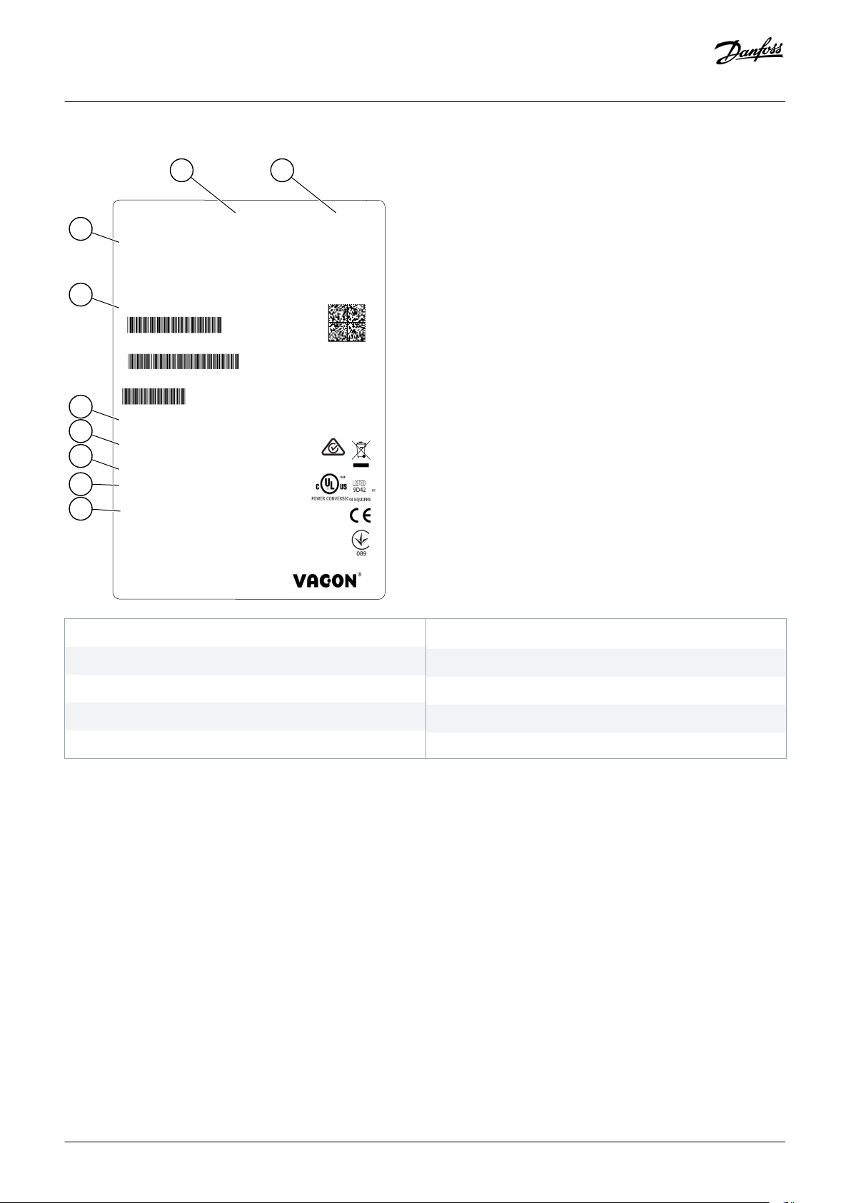
3.3 Package Label
The package label gives detailed information about the delivery.
Danfoss A/S © 2018.06
DPD00910G | 15
Page 16
A B
H
G
F
E
D
C
I
e30bf961.10
1003322235
V00001687465
NXP00875-A2H1SSS-A1A2000000
171208
B.ID :
S/ N:
Type:
AC DR I VE
V00001687465
7DP-008752-116SC8
Made in Finland
Danfoss A/S, 6430 Nordborg, Denmark
135X9219
87A 40°C / 72A 50°C
87A 40°C / 72A 50°C
45kW:400V / 60HP:480V
IP21/Type1
3~AC,0-Uin, 0-320Hz,
Uin:3~AC,380-500V, 50/60Hz,
POWER :
OUTPUT:
INPUT:
Danfoss Limited
0018131571
NXP00002V195
Ma r ks:
Cust . Or d. No :
Appl icat ion :
Firm ware :
7DP-008752-116SC8
Code:
Operating guide | VACON® NXS/NXP Air-cooled
Product Overview
A The batch ID
C The type code
E The mains voltage
G The protection rating
B
The order number of VACON
D The serial number
F The nominal output current
H The firmware code
®
I The order number of the customer
Illustration 1: Package Label of VACON® NXS/NXP AC Drives
3.4 Description of the Type Code
The type designation code of VACON® is made of standard codes and optional codes. Each part of the type designation code agrees to
the data in the order.
Example:
The code can have this format, for example:
NXP00035-A2H1SSS-A1A2C30000+DNOT
•
16 | Danfoss A/S © 2018.06
DPD00910G
Page 17
Operating guide | VACON® NXS/NXP Air-cooled
Table 2: Description of the Type Code
Code Description
VACON This part is same for all the products.
NXP The product range:
• NXP = VACON® NXP
NXS = VACON® NXS
•
0003 The drive rating in amperes. For example, 0003 = 3 A
5 The mains voltage:
• 2 = 208–240 V
•
5 = 380–500 V
• 6 = 525–600 V (IEC)
525–600 V (cULus)
A The control panel:
•
A = standard (text display)
B = no local control panel
•
• F = dummy keypad
• G = graphic display
Product Overview
2 The protection rating:
•
0 = IP00
• 2 = IP21 (UL Type 1)
• 5 = IP54 (UL Type 12)
• T = flange-mounted (through-hole mounted)
H The EMC emission level:
•
C = complies with the category C1 of standard IEC/EN 61800-3 + A1, 1st environment, and nominal voltage less
than 1000 V
H = complies with the category C2 of standard IEC/EN 61800-3 + A1, fixed installations, and nominal voltage
•
less than 1000 V
• L = complies with the category C3 of standard IEC/EN 61800-3 + A1, 2nd environment, and nominal voltage less
than 1000 V
• T = complies with the standard IEC/EN 61800-3 + A1 when used in IT networks (C4).
• N = No EMC emission protection. An external EMC filter is necessary.
1
The brake chopper:
•
0 = No brake chopper
•
1 = Internal brake chopper
(1)
• 2 = Internal brake chopper and resistor, available for:
- 208–240 V (FR4-FR6)
- 380–500 V (FR4-FR6)
Danfoss A/S © 2018.06
DPD00910G | 17
Page 18

Operating guide | VACON® NXS/NXP Air-cooled
Code Description
SSS The hardware changes:
Product Overview
• The supply, the first letter (
Xxx):
- S = 6-pulse connection (FR4 to FR11)
- B = Additional DC-connection (FR8 to FR11)
- J = FR10 to 11 stand-alone with main switch and DC-link terminals
• The mounting, the second letter: (xXx):
- S = Air-cooled drive
• The boards, the third letter (xxX):
- S = Standard boards (FR4 to FR8)
- V = Coated boards (FR4 to FR8)
- F = Standard boards (FR9 to FR11)
- G = Coated boards (FR9 to FR11)
- A = Standard boards (FR10 to FR11 standalone drives)
- B = Coated boards (FR10 to FR11 standalone drives)
- N = separate IP54 (UL Type 12) control box, standard boards (FR9 IP00, ≥ FR10)
- O = separate IP54 (UL Type 12) control box, coated boards (FR9 IP00, ≥ FR10)
- X = separate IP00 control box, standard boards (FR9 IP00)
- Y = separate IP00 control box, coated boards (FR9 IP00)
A1A2C30000 The option boards. 2 characters for each slot. 00 = the slot is not used
The option board abbreviations:
•
A = basic I/O board
B = expander I/O board
•
• C = fieldbus board
• D = special board
• E = fieldbus board
For example, C3 = PROFIBUS DP
+DNOT The optional codes. There are many options.
The options that are related to ordering of paper manuals are:
•
+DNOT = No paper manuals, only Quick Guide and Safety Guide
•
+DPAP = With English paper manuals
• +DPAP+DLDE = With German paper manuals
1
A brake resistor is available as an option for external installation for 208–240 V (FR7-FR11), 380–500 V (FR7-FR11), and 525–690 V (all enclosure sizes).
18 | Danfoss A/S © 2018.06
DPD00910G
Page 19
Operating guide | VACON® NXS/NXP Air-cooled
Product Overview
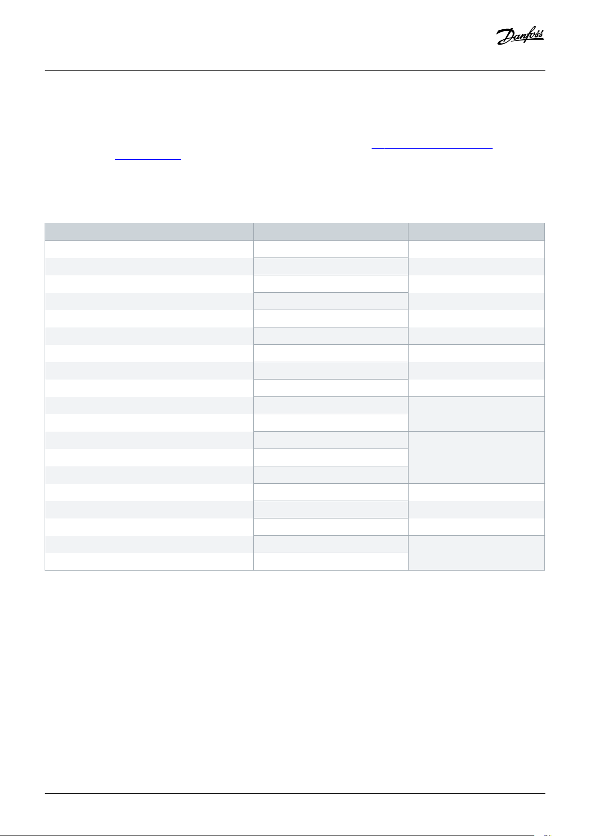
3.5 Enclosure Sizes
Example:
The codes for nominal current and nominal mains voltage are part of the type code (see 3.4 Description of the Type Code) on the
package label (see 3.3 Package Label). Use these values to find out the enclosure size of the AC drive from the table.
In the example "NXP00035-A2H1SSS-A1A2C30000+DNOT", the code for nominal current is 0003 and the code for nominal mains
voltage is 5.
Table 3: Enclosure Sizes
Nominal mains voltage Nominal current Enclosure size
2 (208–240 V) 0003 FR4
0004
0007
0008
0011
0012
0017 FR5
0025
0031
0048 FR6
0061
0075 FR7
0088
0114
0140 FR8
0170
0205
0261 FR9
0300
Danfoss A/S © 2018.06
DPD00910G | 19
Page 20
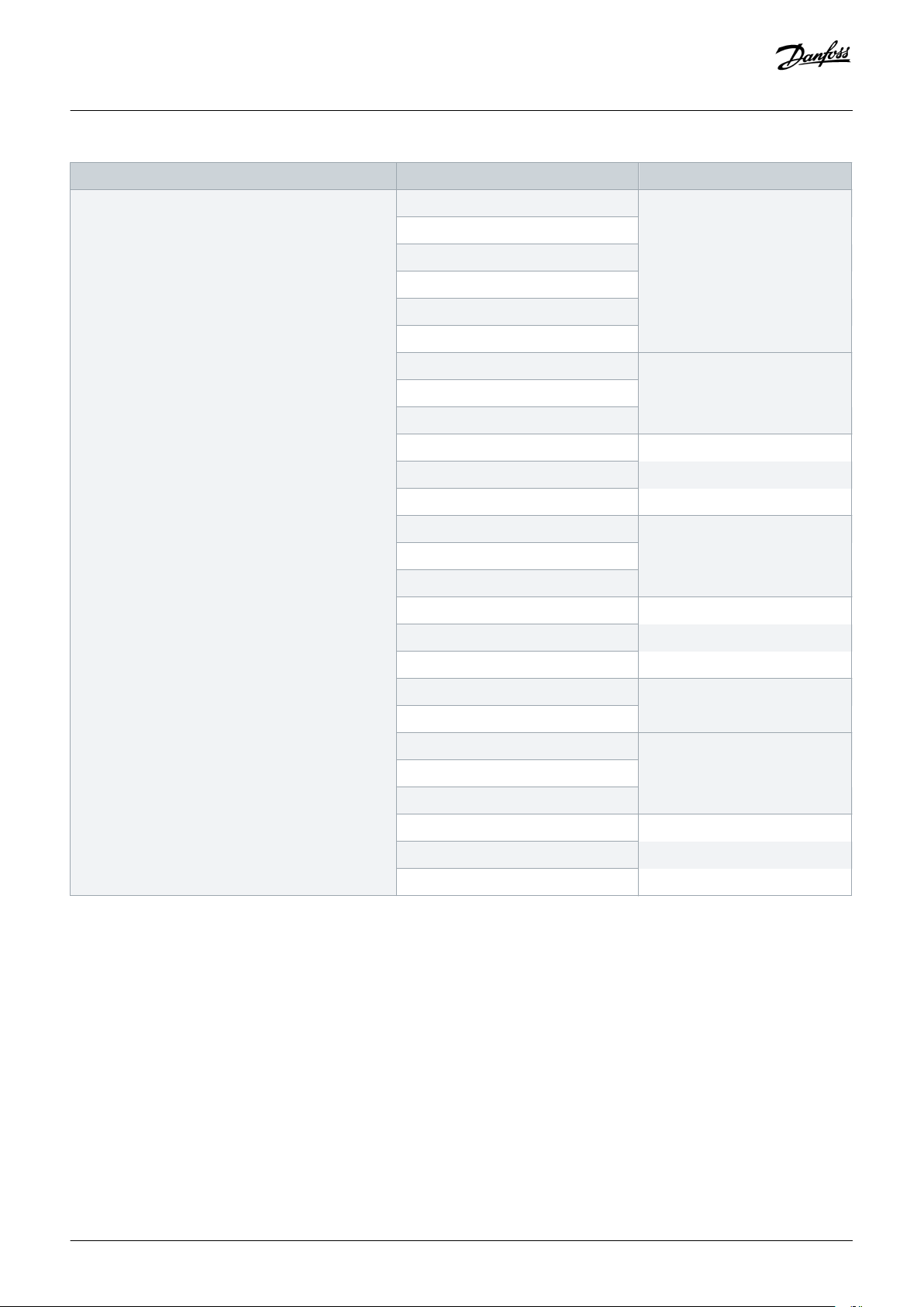
Operating guide | VACON® NXS/NXP Air-cooled
Nominal mains voltage Nominal current Enclosure size
5 (380–500 V) 0003 FR4
0004
0005
0007
0009
0012
0016 FR5
0022
0031
0038 FR6
0045
0061
0072 FR7
Product Overview
0087
0105
0140 FR8
0168
0205
0261 FR9
0300
0385 FR10
0460
0520
0590 FR11
0650
0730
20 | Danfoss A/S © 2018.06
DPD00910G
Page 21
Operating guide | VACON® NXS/NXP Air-cooled
Nominal mains voltage Nominal current Enclosure size
6 (500–690 V) 0004 FR6
0005
0007
0010
0013
0018
0022
0027
0034
0041 FR7
0052
0062 FR8
0080
Product Overview
0100
0125 FR9
0144
0177
0205
0261 FR10
0325
0385
0416
0460 FR11
0502
0590
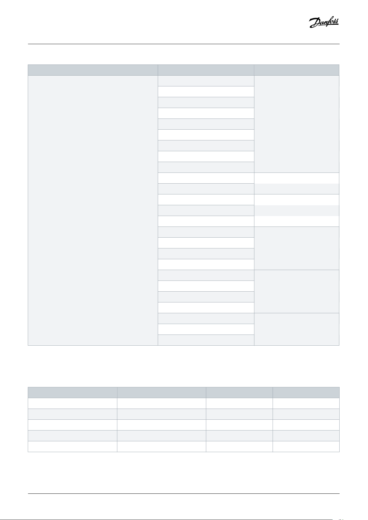
3.6 Available Protection Ratings
Table 4: Available Protection Ratings
Mains voltage Enclosure size IP21 (UL Type 1) IP54 (UL Type 12)
208–240 V FR4-FR9 x x
350–500 V FR4-FR10 x x
350–500 V FR11 x
525–690 V FR4-FR10 x x
525–690 V FR11 x
Danfoss A/S © 2018.06
DPD00910G | 21
Page 22
Operating guide | VACON® NXS/NXP Air-cooled
Product Overview
3.7 Available EMC Classes
The product standard (EMC immunity requirements) IEC/EN 61800-3 + A1 has 5 categories. The VACON® AC drives are divided into 5
EMC classes that have equivalents in the standard. All VACON® NX AC drives comply with the standard IEC/EN 61800-3 + A1.
The type code tells which category requirement the AC drive complies with (see
The category changes when these properties in the AC drive change:
• the level of electromagnetic disturbances
•
the requirements of a power system network
• the installation environment (see the standard IEC/EN 61800-3 + A1)
Table 5: Available EMC Classes
EMC class
in IEC/EN
61800-3 +
A1
C1 C The best EMC protection. These AC drives have the nominal voltage of less than 1000
VACON
equivalent
EMC
class
®
Description Available for
V. They are used in the 1st environment.
3.4 Description of the Type Code).
NOTIC E
If the protection rating of the AC drive is IP21 (UL Type 1), only the conducted
emissions are in the requirements of category C1.
C2 H Includes AC drives in fixed installations. These AC drives have the nominal voltage of
less than 1000 V. The category C2 AC drives can be used in the 1st and the 2nd environment.
380–500 V, FR4
to FR6, IP54 (UL
Type 12)
380–500 V, FR4
to FR9 and
208–240 V, FR4
to FR9
C3 L Includes AC drives that have the nominal voltage of less than 1000 V. These AC drives
are used in the 2nd environment only.
C4 T These AC drives comply with the standard IEC/EN 61800-3 + A1 if they are used in IT
systems. In IT systems, the networks are isolated from ground, or connected to
ground through high impedance to decrease the leakage current.
NOTIC E
If the AC drives are used with other supplies, they do not comply with the EMC
requirements.
To change the EMC class of the VACON® NX AC drive from C2 or C3 to C4, see the
instructions in 6.6 Installation in an IT System.
IP21 (UL Type
1) and IP54 (UL
Type 12) in
380–500 V
FR10 and larger, 525–690 V
FR6 and larger
All products
22 | Danfoss A/S © 2018.06
DPD00910G
Page 23
Operating guide | VACON® NXS/NXP Air-cooled
Product Overview
EMC class
in IEC/EN
61800-3 +
A1
No EMC
emission
protection
VACON
equivalent
EMC
class
N The AC drives of this category do not give EMC emission protection. These drives are
3.8 Control Panel
®
Description Available for
In IP00
installed in enclosures.
NOTIC E
An external EMC filter is usually necessary to comply with the EMC emission
requirements.
NOTIC E
RADIO INTERFERENCE
In a residential environment, this product can cause radio interference.
Take supplementary mitigation measures.
-
3.8.1 Introduction to Control Panel
The control panel is the interface between the AC drive and the user. Use the control panel to control the speed of a motor and
monitor the status of the AC drive. Use it also to set the parameters of the AC drive.
The control panel can be removed from the AC drive. The control panel is isolated from the input line potential.
3.8.2 Keypad
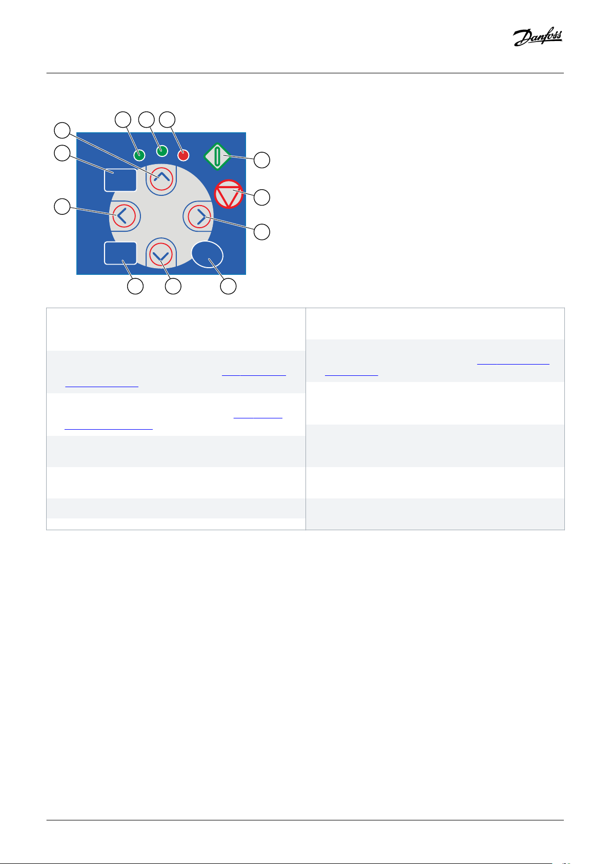
The VACON® keypad has 9 buttons with which you can control the AC drive (and motor), set parameters, and monitor values.
Danfoss A/S © 2018.06
DPD00910G | 23
Page 24
e30bf978.10
K
A B C
L
D
E
J
F
I H G
reset
ready
run
fault
select enter
Operating guide | VACON® NXS/NXP Air-cooled
Product Overview
A The [ready] LED is on when the AC power is connected to the
drive and no faults are active. At the same time, the drive
status indication shows READY.
C The [fault] LED blinks when the AC drive is stopped because
of dangerous conditions (Fault Trip). See 8.5.1 Finding the
Active Faults Menu.
E The Stop button. The button stops the motor (unless the stop
is disabled by the parameter R3.4/R3.6). See 8.4.2 Keypad
Control Parameters M3.
G The [enter] button. Use it to accept a selection, reset the fault
history (push for 2–3 s).
I The [select] button. Use it to move between 2 last displays, for
example, to see how new value changes some other value.
K The [reset] button. Use it to reset a fault.
Illustration 2: Keypad Buttons for VACON® NXP
B The [run] LED is on when the drive operates. The LED blinks
when the Stop button is pushed and the drive ramps down.
D The Start button. When the keypad is the active control
mode, this button starts the motor. See 8.4.3 Changing the
Control Mode.
F The Menu button Right. Use it to move forward in the menu,
move the cursor right (in the parameter menu) and to go to
the edit mode.
H The Browser button Down. Use it to scroll the main menu
and the pages of different submenus and to decrease a
value.
J The Menu button Left. Use it to move back in the menu, move
the cursor left (in the Parameter menu).
L The Browser button Up. Use it to scroll the main menu and
the pages of different submenus and to increase a value.
24 | Danfoss A/S © 2018.06
DPD00910G
Page 25
K
A
B
C
L
D
E
J
F
I
H
G
reset
START
STOP
ready
run
fault
select
enter
e30bg072.10
Operating guide | VACON® NXS/NXP Air-cooled
Product Overview
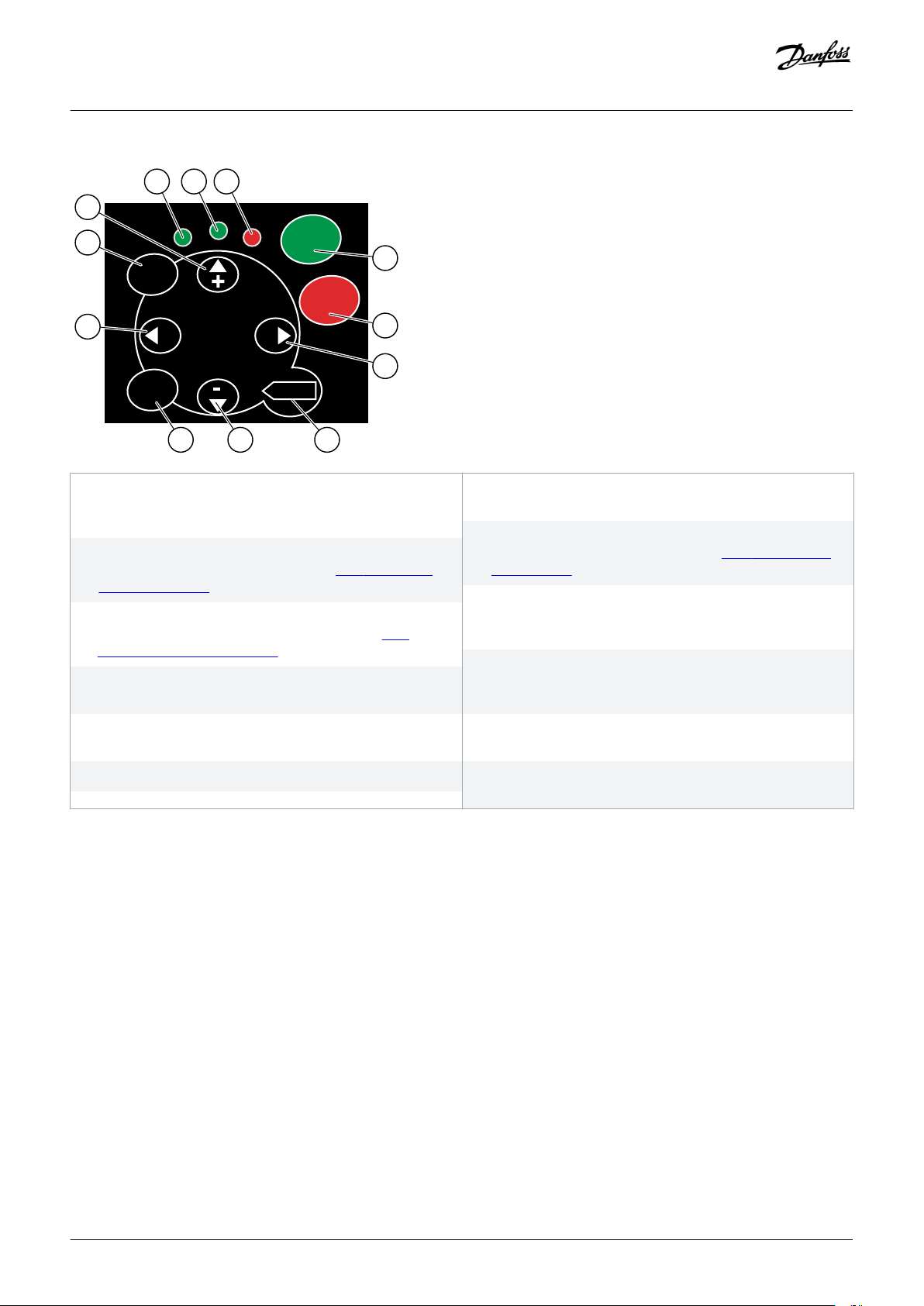
A The [ready] LED is on when the AC power is connected to the
drive and no faults are active. At the same time, the drive
status indication shows READY.
C The [fault] LED blinks when the AC drive is stopped because
of dangerous conditions (Fault Trip). See 8.5.1 Finding the
Active Faults Menu.
E The [STOP] button. The button stops the motor (unless the
stop is disabled by the parameter R3.4/R3.6). See 8.4.2
Keypad Control Parameters M3.
G The [enter] button. Use it to accept a selection, reset the fault
history (push for 2–3 s).
I The [select] button. Use it to move between 2 last displays, for
example, to see how new value changes some other value.
K The [reset] button. Use it to reset a fault.
Illustration 3: Keypad Buttons for VACON® NXS
3.8.3 Display
B The [run] LED is on when the drive operates. The LED blinks
when the Stop button is pushed and the drive ramps down.
D The [START] button. When the keypad is the active control
mode, this button starts the motor. See 8.4.3 Changing the
Control Mode.
F The Menu button Right. Use it to move forward in the menu,
move the cursor right (in the parameter menu) and to go to
the edit mode.
H The Browser button Down. Use it to scroll the main menu
and the pages of different submenus and to decrease a
value.
J The Menu button Left. Use it to move back in the menu, move
the cursor left (in the Parameter menu).
L The Browser button Up. Use it to scroll the main menu and
the pages of different submenus and to increase a value.
Danfoss A/S © 2018.06
DPD00910G | 25
Page 26
A
K
L
M
B C D E
H
I
J
F G
e30bf979.10
READY
FAULT
STOP
RUN
Bus/CommKeypadI/O term
ALARM
Operating guide | VACON® NXS/NXP Air-cooled
Product Overview
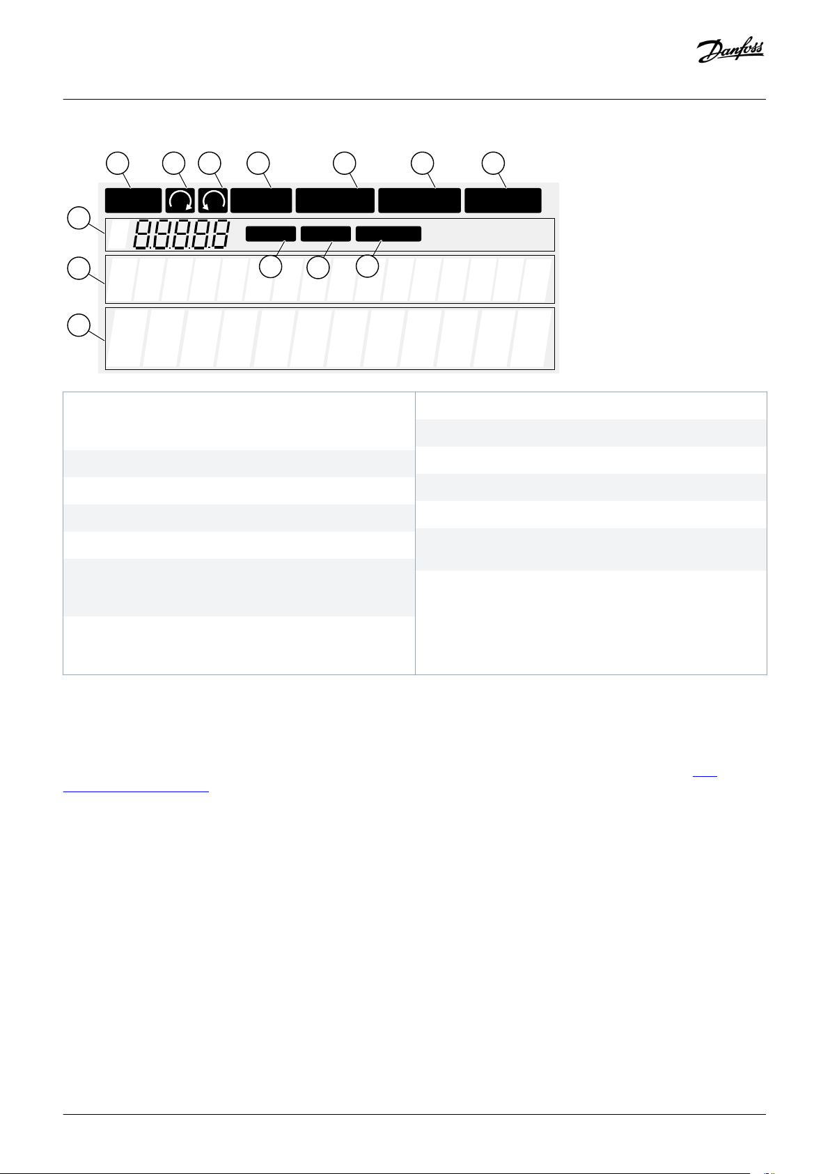
A The motor is in RUN state. The indication starts to blink when
a stop command is given and blinks while the speed
continues to decrease.
C The motor rotation direction is reverse.
E The AC power is on.
G A fault is given and the AC drive is stopped.
I The control panel is the active control mode.
K The location indication. The line shows the symbol and
number of the menu, parameter and so on. For example,
M2 = Menu 2 (Parameters) or P2.1.3 = Acceleration time.
M The value line. The line shows the numerical and text values
of references, parameters and so on. It also shows the
number of submenus that are available in each menu.
Illustration 4: Display Indications
The drive status indicators (A-G) give information about the status of the motor and the AC drive.
The control mode indications (H, I, J) show the selection of the control mode. The control mode tells from where the START/STOP
commands are given and reference values are changed. To make this selection, go to the Keypad control menu (M3) (see 8.4.3
Changing the Control Mode).
B The motor rotation direction is forward.
D The drive does not operate.
F An alarm is given.
H The I/O terminals is the active control mode.
J The fieldbus is the active control mode.
L The description line. The line shows the description of the
menu, value, or fault.
The three text lines (K, L, M) give information about the current location in the menu structure and the operation of the drive.
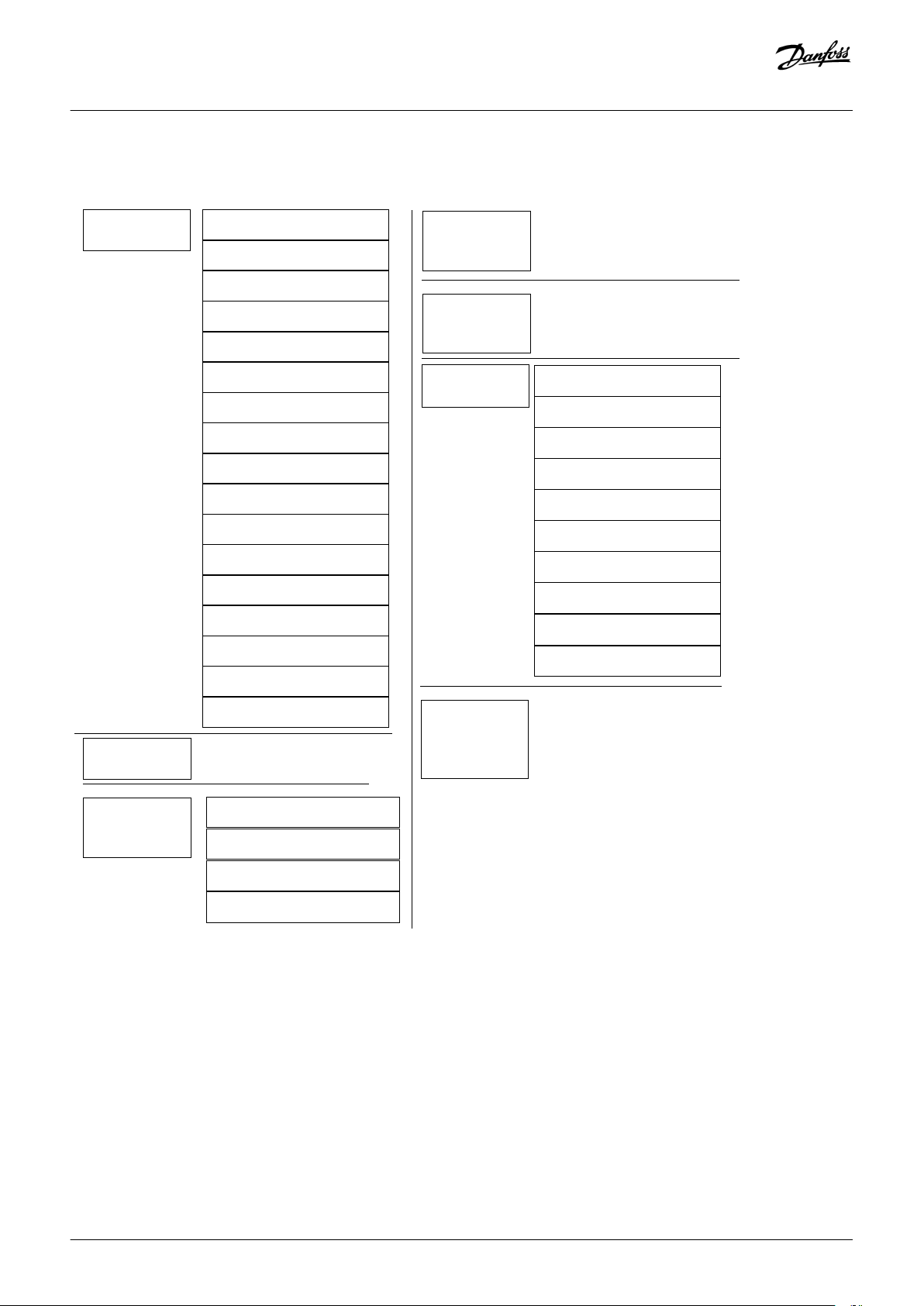
3.8.4 Basic Menu Structure
The data of the AC drive is in menus and submenus. The figure shows the basic menu structure of the AC drive.
This menu structure is only an example and the contents and items can vary depending on the application in use.
26 | Danfoss A/S © 2018.06
DPD00910G
Page 27
e30bf981.10
Main menu
Submenus
Submenus
See Application Manual
Main menu
M1 Monitor
V1.1 Output frequency
V1.2 Frequency ref.
V1.3 Motor speed
V1.4 Motor current
M3 Keypad
control
P3.1 Control place
R3.2 Keypad reference
P3.3
Direction (on keypad)
P3.4 Stop button
V1.5 Motor torque
V1.6 Motor power
V1.7 Motor voltage
V1.8 DC-link voltage
S6.1 Language selection
S6.2
Application selection
S6.3 Copy parameters
S6.4 Compare param.
S6.5 Security
S6.6 Keypad settings
S6.7 Hardware settings
S6.8 System information
S6.9 Power monitor
S6.11 Power
multi-monitor
V1.9 Unit temperature
V1.10 Motor temp.
V1.11 Analogue Input 1
V1.12 Analogue Input 2
V1.13 Current input
V1.14 DIN1, DIN2, DIN3
V1.15 DIN4, DIN5, DIN6
V1.16 Analogue output
V1.17 Multimonit. items
M2
Parameters
M6 System
menu
M4 Active
faults
M5 Fault
history
M7 Expand er boards
Operating guide | VACON® NXS/NXP Air-cooled
Product Overview
Illustration 5: Basic Menu Structure of the AC Drive
Danfoss A/S © 2018.06
DPD00910G | 27
Page 28

Operating guide | VACON® NXS/NXP Air-cooled
4 Receiving the Delivery
4.1 Checking the Delivery
Context:
Before a VACON® AC drive is sent to the customer, the manufacturer makes many tests on the drive.
Receiving the Delivery
28 | Danfoss A/S © 2018.06
DPD00910G
Page 29
1
2
3 4 5 6 7 8
e30bf975.10
2
3
4
1
e30bf976.10
Operating guide | VACON® NXS/NXP Air-cooled
Receiving the Delivery
Procedure
1. After removing the packaging, examine the drive for transport damages.
If the drive was damaged during the shipping, speak to the cargo insurance company or the carrier.
2. To make sure that the delivery is correct, compare the order data to the data on the package label, see 3.3 Package Label.
If the delivery does not agree with the order, speak to the vendor immediately.
3. To make sure that the contents of the delivery is correct and complete, compare the type code of the product to the type code, see
3.4 Description of the Type Code.
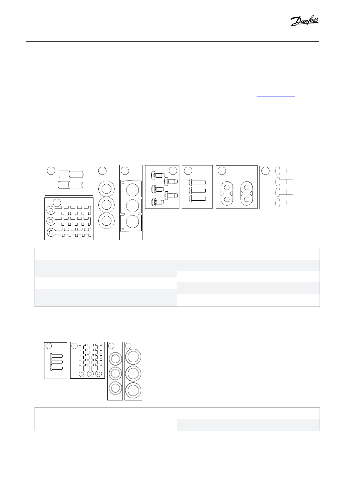
4. Check that the accessories bag contains the items shown in the figure. These accessories are part of the electrical installation. The
contents of the accessories bag is different for different enclosure sizes and protection ratings.
FR4-FR6
1 The grounding terminals (FR4, FR5), 2 pieces
3 The rubber grommets (sizes vary from class to class),
2 The grounding clamps for control cable, 3 pieces
4 The cable entry plate
3 pieces
6 Screws, M4x16, 3 pieces
5 Screws, M4x10, 5 pieces
8 The grounding screws M5x16 (FR6), 4 pieces
7 The grounding clamps for grounding conductor (FR6), 2
pieces
Illustration 6: Contents of the Accessories Bag for FR4-FR6
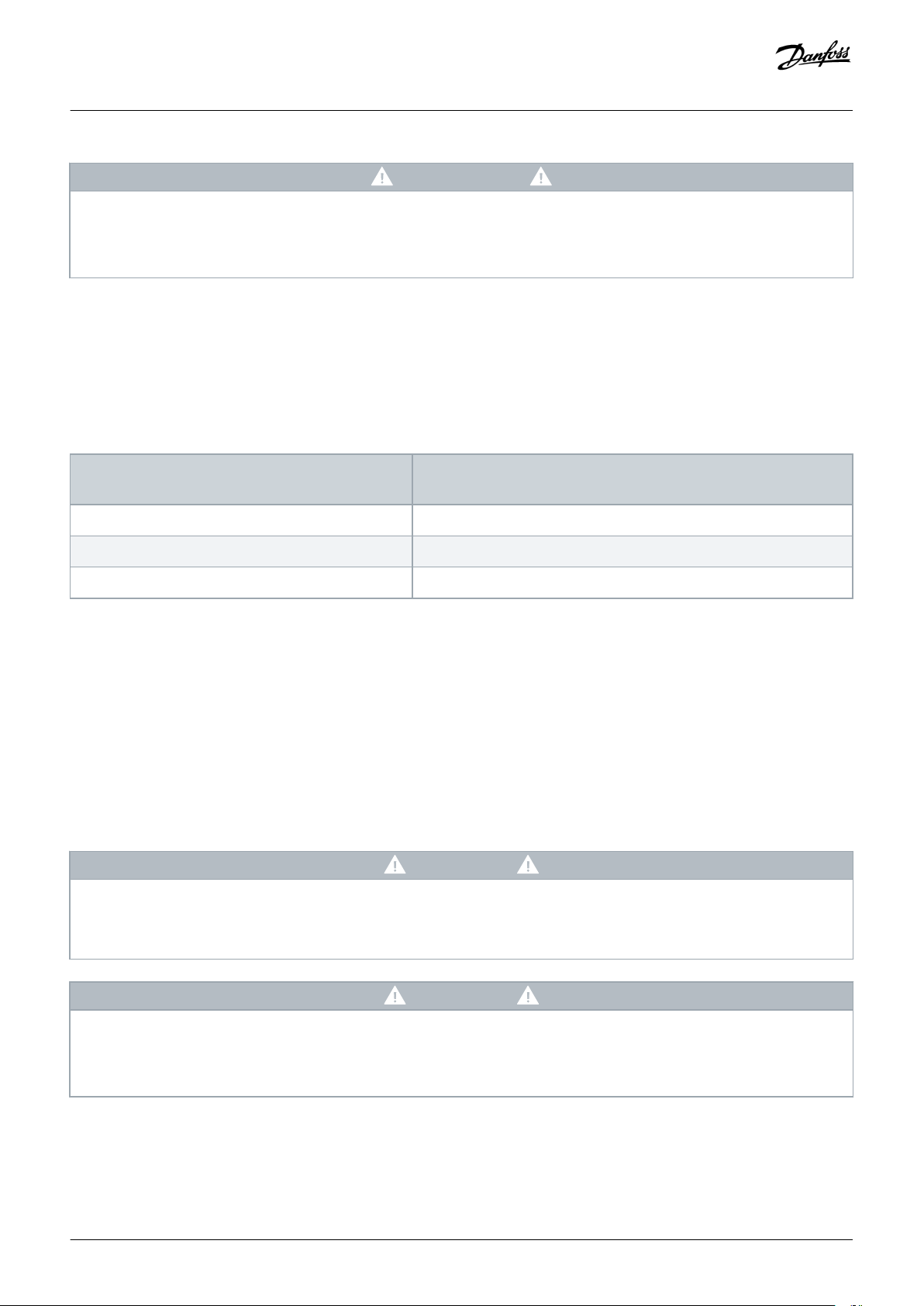
FR7-8
1 Screws, M4x16, 3 pieces 2 The grounding clamps for control cable, 3 pieces
4 The rubber grommets GDM36 (FR7), 3 pieces
Danfoss A/S © 2018.06
DPD00910G | 29
Page 30

Operating guide | VACON® NXS/NXP Air-cooled
3 The rubber grommets GD21 (FR7 IP54/UL Type 12),
3 pieces / (FR8), 6 pieces
Illustration 7: Contents of the Accessories Bag for FR7-FR8
Receiving the Delivery
4.2 Storing the Product
Context:
If the product has to be stored before installing it, follow these instructions.
Procedure
1. If the AC drive must be stored before using it, make sure that the ambient conditions agree to the following:
• Storage temperature: –40…+70° C (-40...+158° F)
• Relative humidity: 0–95%, no condensation
2. If the AC drive must be kept in storage for a long time, connect the power to the AC drive each year. Keep the power on for a
minimum of 2 hours.
3. If the storage time is more than 12 months, charge the electrolytic DC capacitors with caution. To reform the capacitors, obey the
instructions in 10.2 Reforming the Capacitors.
We do not recommend a long storage time.
4.3 Lifting the Product
Context:
Speak to the factory or the local distributor to get information on how to lift the AC drive safely.
Prerequisites:
The weights of AC drives of different enclosure sizes are very different. It can be necessary to use a lifting device to move the drive from
its package.
Procedure
1. Check the weight of the AC drive, see
2. To lift the AC drives larger than FR7 out of the package, use a jib crane.
3. After lifting the drive, check for signs of damage on the drive.
12.1 Weights of the AC Drive.
4.4 Using the Product Modified Label
Context:
In the accessories bag, there is also a "product modified" label. The function of the label is to tell the service personnel about the
changes that are made in the AC drive.
30 | Danfoss A/S © 2018.06
DPD00910G
Page 31

e30bf977.10
Option board: NXOPT......... Date:............
IP54 upgrade/Collar
EMC level modified: H/L to T
Drive modified:
in slot: A B C D E Date:............
Date:............
Date:............
Operating guide | VACON® NXS/NXP Air-cooled
Illustration 8: The Product Modified Label
Procedure
1. Attach the label on the side of the AC drive to know where to find it.
2. If changes are made in the AC drive, write the change on the label.
Receiving the Delivery
Danfoss A/S © 2018.06
DPD00910G | 31
Page 32

Operating guide | VACON® NXS/NXP Air-cooled
Mounting the Unit
5 Mounting the Unit
5.1 Environmental Requirements
5.1.1 General Environmental Requirements
In environments with airborne liquids, particles, or corrosive gases, ensure that the protection rating of the equipment matches the
installation environment. Failure to meet requirements for ambient conditions can reduce the lifetime of the AC drive. Ensure that
requirements for humidity, temperature, and altitude are met.
Vibration and shock
The AC drive complies with requirements for units mounted on the walls and floors of production premises, and in panels bolted to
walls or floors. For detailed ambient conditions specifications, see 12.8 VACON NXP Technical Data.
Installation requirements:
• Make sure that there is sufficiently free space around the AC drive for cooling, see 5.2.2 Cooling of FR4 to FR9 or 5.2.3 Cooling of
Standalone AC drives (FR10 to FR11).
• Some free space is also necessary for maintenance.
•
Make sure that the mounting surface is sufficiently flat.
5.1.2 High Altitude Installation
The density of air decreases when the altitude increases and the pressure decreases. When the air density decreases, the thermal
capacity decreases (that is, less air removes less heat) and the resistance to electric field (breakdown voltage/distance) decreases.
The full thermal performance of VACON® NX AC drives is designed for installation up to 1000 m altitude. The electric insulation is
designed for installations up to 2000 m altitude.
Higher installation locations are possible, when obeying the derating guidelines in this chapter.
Above 1000 m, decrease the limited maximum load current by 1% for each 100 m. For example, at 2500 m altitude, decrease the load
current down to 85% of the rated output current (100% – (2500–1000 m) / 100 m x 1% = 85%).
When using fuses at high altitudes, the cooling effect of the fuse decreases as the density of the atmosphere decreases.
When using fuses above 2000 meters, the continuous rating of the fuse:
I = In*(1- (h-2000)/100*0.5/100)
Where
I = Current rating at high altitude
In = Rated current of a fuse
h = Altitude in meters
32 | Danfoss A/S © 2018.06
DPD00910G
Page 33

0
500
1000
1500
2000
2500
3000
3500
4000
4500
5000
0%
10%
30%
50%
70%
20%
40%
60%
80%
90%
100%
110%
A
e30bg030.10
Operating guide | VACON® NXS/NXP Air-cooled
Mounting the Unit
A Loadability
Illustration 9: Loadability in High Altitudes
For permitted maximum altitudes, see 12.8 VACON NXP Technical Data.
For information on option boards and I/O signals and relay outputs, see VACON® NX I/O Boards User Manual.
5.2 Cooling Requirements
5.2.1 General Cooling Requirements
The AC drive produces heat in operation. The fan moves air and decreases the temperature of the drive. Make sure that there is
sufficiently free space around the drive.
Make sure that the temperature of the cooling air does not go above the maximum ambient operating temperature or below the
minimum ambient operating temperature of the drive.
5.2.2 Cooling of FR4 to FR9
If many AC drives are installed above each other, the necessary free space is C + D (see
from the lower drive goes to a different direction than the air intake of the top drive.
illustration 10). Make also sure that the outlet air
Danfoss A/S © 2018.06
DPD00910G | 33
Page 34

A
A
2
D
A
A
2
B
B
C
e30bg010.10
Operating guide | VACON® NXS/NXP Air-cooled
Mounting the Unit
A The clearance around the drive (see also B and C)
B The distance from a drive to a second drive, or the distance to
the cabinet wall
C The free space above the drive
D The free space below the drive
Illustration 10: Installation Space
Table 6: Minimum Clearances around the AC Drive in mm (in inch)
Drive type A B C D
0003 2-0012 2
0003 5-0012 5
0017 2-0031 2
0016 5-0031 5
0048 2-0061 2
0038 5-0061 5
20
(0.79)
20
(0.79)
30
(1.18)
20
(0.79)
20
(0.79)
20
(0.79)
100
(3.94)
120
(4.72)
160
(6.30)
50
(1.97)
60
(2.36)
80
(3.15)
0004 6-0034 6
34 | Danfoss A/S © 2018.06
DPD00910G
Page 35

Operating guide | VACON® NXS/NXP Air-cooled
Drive type A B C D
Mounting the Unit
0075 2-0114 2
0072 5-0105 5
80
(3.15)
80
(3.15)
300
(11.81)
0041 6-0052 6
0140 2-0205 2
0140 5-0205 5
0062 6-0100 6
0261 2-0300 2
0261 5-0300 5
80
(3.15)
()
50
(1.97)
80
(3.15)
80
(3.15)
300
(11.81)
400
(15.75)
0125 6-0208 6
To change the fan with the motor cables connected, the necessary clearance on the 2 sides of the drive is 150 mm (5.91 inch).
The minimum clearance to change the fan.
Table 7: Necessary Quantity of Cooling Air
Drive type
0003 2-0012 2
The quantity of cooling air [m3/h]
70 41.2
The quantity of cooling air [CFM]
100
(3.94)
300
(11.81)
250 / 350
(9.84) / (13.78)
()
0003 5-0012 5
0017 2-0031 2
0016 5-0031 5
0048 2-0061 2
0038 5-0061 5
0004 6-0034 6
0075 2-0114 2
0072 5-0105 5
0041 6-0052 6
0140 2-0205 2
0140 5-0205 5
0062 6-0100 6
0261 2-0300 2
0261 5-0300 5
0125 6-0208 6
190 112
425 250
425 250
650 383
1000 589
Danfoss A/S © 2018.06
DPD00910G | 35
Page 36

B
C
A
e30bg011.10
Operating guide | VACON® NXS/NXP Air-cooled
5.2.3 Cooling of Standalone AC drives (FR10 to FR11)
Mounting the Unit
A The minimum distance to the side walls or adjacent
components
C Free space in front of the cabinet
Illustration 11: Minimum Clearances around the AC Drive
Table 8: Minimum Clearances around the AC Drive in mm (in inch)
Drive type A B C
0385 5-0730 5
0261 6-0590 6
Table 9: Necessary Quantity of Cooling Air
Drive type
0385 5-0520 5
0261 6-0416 6
0590 5-0730 5
0460 6-0590 6
The quantity of cooling air [m3/h]
2000 900
3000 1765
20
(0.79)
B The minimum distance from the top of the cabinet
200
(7.87)
The quantity of cooling air [CFM]
800
(31.50)
For more information on the power losses based on the switching frequency, see http://drives.danfoss.com/knowledge-center/energy-
efficiency-directive/#/.
36 | Danfoss A/S © 2018.06
DPD00910G
Page 37

Operating guide | VACON® NXS/NXP Air-cooled
Mounting the Unit
5.3 Installation Sequence
5.3.1 Installation Sequence for Wall-mounted AC Drives
Context:
Use these instructions to install the Wall-mounted AC Drive.
Procedure
1. Select the mounting option:
- Horizontal
- Vertical
If the drive is installed in a horizontal position, there is no protection against drops of water that fall vertically.
- Flange mounting
The AC drive can also be installed into the cabinet wall with a flange mounting option (throughhole mounting). With the flange
mounting, the protection rating of the power unit is IP54 (UL Type 12) and the protection rating of the control unit is IP21
(UL Type 1).
2. Check the dimensions of the AC drive, see
3. Make sure that there is sufficiently free space around the AC drive for cooling, see
also necessary for maintenance.
4. Attach the AC drive with the screws and other components in the delivery.
12.2.1 List of Dimension Information.
5.2.2 Cooling of FR4 to FR9. Some free space is
5.3.2 Installation Sequence for Standalone AC drives
Context:
Use these instructions to install the standalone AC drive.
Procedure
1. Make sure that the mounting surface is sufficiently flat.
2. Check the dimensions of the AC drive, see 12.2.4.1 Dimensions for FR10-FR11.
3. Make sure that there is sufficiently free space around the AC drive for cooling, see 5.2.3 Cooling of Standalone AC drives (FR10 to
FR11). Some free space is also necessary for maintenance.
4. The enclosures have fixing holes. If needed, fix the AC Drive to the wall.
Danfoss A/S © 2018.06
DPD00910G | 37
Page 38

A
B
C
e30bg078.10
U/T1
V/T2
W/T3
L1
L2
L3
B-
B+/R+
R-
R
Operating guide | VACON® NXS/NXP Air-cooled
Electrical Installation
6 Electrical Installation
6.1 Cable Connections
The mains cables are connected to terminals L1, L2, and L3. The motor cables are connected to terminals U, V, and W.
A The control panel
C The power unit
Illustration 12: Principal Connection Diagram
For EMC-compliant installation, see 6.2 EMC-compliant Installation.
B The control unit
6.1.1 General Cable Requirements
Use cables with a minimum heat resistance of +70 °C (158 °F). In the selection of the cables and the fuses, refer to the nominal output
current of the drive. Find the nominal output current on the nameplate.
We recommend selecting the cables and the fuses to agree with the output current because the input current of the AC drive is almost
the same as the output current.
For information on how to make the cable installation to comply with the UL standards, see 6.1.2 UL Standards on Cabling.
If the motor temperature protection of the drive (see VACON® All in One Application Manual) is used as an overload protection, select
the cable to agree with the protection. If 3 or more cables are used in parallel for larger AC drives, use a separate overload protection
for each cable.
38 | Danfoss A/S © 2018.06
DPD00910G
Page 39

Operating guide | VACON® NXS/NXP Air-cooled
These instructions are valid only for processes that have 1 motor and 1 cable connection from the AC drive to the motor. In other
conditions, speak to the manufacturer to get more information.
Electrical Installation
6.1.2 UL Standards on Cabling
To comply with the UL (Underwriters Laboratories) regulations, use a UL-approved copper wire with a minimum heat resistance of
60 °C or 75 °C (140 °F or 167 °F). To comply with the standards, use cables with +90 °C (194 °F) heat resistance for sizes 0170 2 and
0168 5 (FR8), and 0261 2, 0261 5, 0300 2 and 0300 5 (FR9).
Use Class 1 wire only.
When the drive has Class T and J fuses, it can be used on a circuit that gives a maximum of 100 000 rms symmetrical amperes, and a
maximum of 600 V.
The integral solid-state short-circuit protection does not give a branch circuit protection. Obey the National Electric Code and any
additional local codes to get the branch circuit protection. Only fuses give the branch circuit protection.
For the tightening torques of the terminals, see 12.6 Tightening Torques of the Terminals.
6.1.3 Cable Selection and Dimensioning
Find the typical sizes and types of cables used with the AC drive the tables in 12.3.1 List of Cable and Fuse Size Information. In the
selection of cables, refer to local regulations, cable installation conditions and cable specification.
The dimensions of the cables must comply with the requirements of the standard IEC60364-5-52.
• The cables must be PVC-isolated.
•
The maximum ambient temperature is +30 °C (86 °F).
• The maximum temperature of the cable surface is +70 °C (158 °F).
• Use only cables with a concentric copper shield.
• The maximum number of parallel cables is 9.
When using parallel cables, make sure to obey the requirements of the cross-sectional area and the maximum number of cables.
For important information on the requirements of the grounding conductor, see
For the correction factors for each temperature, see the standard IEC60364-5-52.
6.3 Grounding.
6.1.4 Cable Selection and Dimensioning, North America
Find the typical sizes and types of cables used with the AC drive the tables in
selection of cables, refer to local regulations, cable installation conditions and cable specification.
The dimensions of the cables must comply with the requirements of the National Electric Code (NEC) and the Canadian Electric
Code (CEC).
12.3.1 List of Cable and Fuse Size Information. In the
• The cables must be PVC-isolated.
The maximum ambient temperature is +86 °F.
•
• The maximum temperature of the cable surface is +158 °F.
• Use only cables with a concentric copper shield.
• The maximum number of parallel cables is 9.
Danfoss A/S © 2018.06
DPD00910G | 39
Page 40

A
B
B
C
FR4-9/FR10/
FR11 0460 6 & 0502 6
FR11 *)
e30bg080.10
Operating guide | VACON® NXS/NXP Air-cooled
Electrical Installation
When using parallel cables, make sure to obey the requirements of the cross-sectional area and the maximum number of cables.
For important information on the requirements of the grounding conductor, see the NEC and CEC.
For the correction factors for each temperature, see the instructions of NEC and CEC.
6.1.5 Fuse Selection
We recommend the fuse type gG/gL (IEC 60269-1). To make a selection of the fuse voltage rating, refer to the mains. Do not use larger
fuses than what is recommended.
Find the recommended fuses in tables in 12.3.1 List of Cable and Fuse Size Information.
Make sure that the operation time of the fuse is less than 0.4 s. The operation time agrees with the fuse type and the impedance of the
supply circuit. For more information on faster fuses, speak to the manufacturer. The manufacturer can also recommend some aR (UL
recognized, IEC 60269-4) and gS (IEC 60269-4) fuse ranges.
6.1.6 Principle of the Power Unit Topology
The principles for mains and motor connections of the basic 6-pulse drive in enclosure sizes FR4 to FR11 show in illustration 13.
A Single input
C Double input
Illustration 13: Topology of Enclosure Sizes FR4 – FR11
B Single output
* The FR11 types 0460 6 and 0502 6 have single input terminal.
6.1.7 Brake Resistor Cables
VACON® NXS/NXP AC drives have terminals for the DC supply and an optional external brake resistor. These terminals are identified
with B–, B+/R+, and R–. The DC bus connection is made to terminals B– and B+ and the brake resistor connection to R+ and R–. Find
the dimensions that we recommend for the brake resistor cables in the tables linked in 6.1.7 Brake Resistor Cables.
40 | Danfoss A/S © 2018.06
DPD00910G
Page 41

Operating guide | VACON® NXS/NXP Air-cooled
Electrical Installation
CAUTI O N
SHOCK HAZARD FROM MULTI-CONDUCTOR CABLES
With a multi-conductor cable, the conductors that are not connected can cause an accidental contact with a conducting
component.
If a multi-conductor cable is used, cut off all conductors that are not connected.
-
The enclosure sizes FR8 and larger have the DC connection as optional.
If it is necessary to connect an external brake resistor, see VACON® Brake Resistor Manual. See also
8.7.8.2 Setting the Internal Brake
Resistor Connection.
6.2 EMC-compliant Installation
For cable selections in different EMC levels, see table 10.
To comply with the EMC levels, use a grommet when installing the motor cable at the two ends. For the EMC levels C1 and C2, it is
necessary to have a 360º grounding of the shield with grommets in the motor end.
Table 10: Recommendations for Cables
Cable
type
Motor cable
Mains cable
Category C1 and C2
(1)
A symmetrical power cable with a compact low-impedance shield.
A cable for the specified mains voltage.
We recommend an NKCABLES /MCCMK, SAB/
ÖZCUY-J or equivalent cable. See illustration 14.
A power cable for a fixed installation.
A cable for the specified mains voltage.
Category C3
A symmetrical power cable with a concentric protection wire.
A cable for the specified mains voltage.
We recommend an NKCABLES/MCMK cable. See illustration 14.
(2)
Category C4
(2)
No EMC protection
(2)
A shielded cable is not necessary.
We recommend an NKCABLES/MCMK cable.
Control
A shielded cable with a compact low-impedance shield, for example an NKCABLES/ JAMAK, or an SAB/ÖZCuY-O cable.
cable
1
st
1
environment
2
2nd environment
For the definitions of EMC protection levels, see IEC/EN 61800-3 + A1.
Danfoss A/S © 2018.06
DPD00910G | 41
Page 42

A
C
B
e30bg079.10
Operating guide | VACON® NXS/NXP Air-cooled
Electrical Installation
A The PE conductor and the shield
C The shield
Illustration 14: Cables with PE Conductors
In all the enclosure sizes, to comply with the EMC standards, use the default values of the switching frequencies.
If installing a safety switch, make sure that the EMC protection continues from the start of the cables until their ends.
The drive must obey the standard IEC 61000-3- 12. To obey it, the short circuit power SSC must be a minimum of 120 R
interface point between mains and the public mains. Make sure to connect the drive and the motor to mains with a short circuit power
SSC that is a minimum of 120 R
. If necessary, contact the mains operator.
SCE
B The PE conductors
SCE
at the
6.2.1 Installation in a Corner-grounded Network
Corner-grounding can be used with the drive types (FR4 to FR9) with a rating of 3–300 A with a 208–240 V mains, and 261–730 A with a
380–500 V mains. In these conditions, change the EMC protection level to C4. See the instructions in
Do not use corner-grounding with the drive types (FR4 to FR8) with a rating of 3–205 A with a 380–500 V mains or with a 525–690 V
mains.
Corner-grounding is permitted for the FR4-9 drives (main voltage 208–240 V) up to 3000 m and for the FR9-FR11 drives (main voltage
380–500 V) up to 2000 m.
6.6 Installation in an IT System.
6.3 Grounding
Ground the AC drive in accordance with applicable standards and directives.
CAUTI O N
DAMAGE TO THE AC DRIVE FROM INSUFFICIENT GROUNDING
Not using a grounding conductor can damage the drive.
Make sure that the AC drive is always with a grounding conductor that is connected to the grounding terminal that is
-
identified with the PE symbol.
42 | Danfoss A/S © 2018.06
DPD00910G
Page 43
Operating guide | VACON® NXS/NXP Air-cooled
Electrical Installation
WARN I N G
LEAKAGE CURRENT HAZARD
Leakage currents exceed 3.5 mA. Failure to ground the drive properly can result in death or serious injury.
Ensure the correct grounding of the equipment by a certified electrical installer.
-
The standard EN 61800-5-1 tells that 1 or more of these conditions for the protective circuit must be true.
The connection must be fixed.
• The protective earthing conductor must have a cross-sectional area of minimum 10 mm2 Cu or 16 mm2 Al. OR
•
There must be an automatic disconnection of the mains, if the protective earthing conductor breaks. OR
• There must be a terminal for a second protective earthing conductor in the same cross-sectional area as the first protective
earthing conductor.
Cross-sectional area of the phase conductors (S) [mm2]
S ≤ 16 S
16 < S ≤ 35 16
35 < S S/2
The values of the table are valid only if the protective earthing conductor is made of the same metal as the phase conductors. If this is
not so, the cross-sectional area of the protective earthing conductor must be determined in a manner that produces a conductance
equivalent to that which results from the application of this table.
The cross-sectional area of each protective earthing conductor that is not a part of the mains cable or the cable enclosure, must be a
minimum of:
• 2.5 mm2 if there is mechanical protection, and
•
4 mm2 if there is not mechanical protection. With cord-connected equipment, make sure that the protective earthing conductor in
the cord is the last conductor to be interrupted, if the strain-relief mechanism breaks.
Obey the local regulations on the minimum size of the protective earthing conductor.
The minimum cross-sectional area of the protective earthing
conductor in question [mm2]
NOTIC E
MALFUNCTION OF FAULT CURRENT PROTECTIVE SWITCHES
Because there are high capacitive currents in the AC drive, it is possible that the fault current protective switches do not
operate correctly.
NOTIC E
VOLTAGE WITHSTAND TESTS
Doing voltage withstand tests can damage the drive.
Do not do voltage withstand tests on the AC drive. The manufacturer has already done the tests.
-
Danfoss A/S © 2018.06
DPD00910G | 43
Page 44

Operating guide | VACON® NXS/NXP Air-cooled
Electrical Installation
WARN I N G
SHOCK HAZARD FROM PE CONDUCTOR
The drive can cause a DC current in the PE conductor. Failure to use a residual current-operated protective (RCD) device Type B
or a residual current-operated monitoring (RCM) device can lead to the RCD not providing the intended protection and
therefore can result in death or serious injury.
Use a type B RCD or RCM device on the mains side of the drive.
-
6.4 Get Access and Locate the Terminals
6.4.1 Get Access and Locate the Terminals for FR4
Context:
Follow these instructions to open the AC drive for installing the cables, for example.
44 | Danfoss A/S © 2018.06
DPD00910G
Page 45

e30bg082.10
e30bg084.10
Operating guide | VACON® NXS/NXP Air-cooled
Procedure
1. Open the cover of the AC drive.
2. Remove the screws of the cable cover. Remove the cable cover. Do not open the cover of the power unit.
Electrical Installation
3. Locate the terminals.
Danfoss A/S © 2018.06
DPD00910G | 45
Page 46

A
D
B
C
e30bg089.10
Operating guide | VACON® NXS/NXP Air-cooled
Electrical Installation
A Control terminals
C Motor terminals
Illustration 15: FR4 Terminals
B Brake resistor terminals
D Grounding terminals
6.4.2 Get Access and Locate the Terminals for FR5
Context:
Follow these instructions to open the AC drive for installing the cables, for example.
46 | Danfoss A/S © 2018.06
DPD00910G
Page 47

e30bg083.10
e30bg084.10
Operating guide | VACON® NXS/NXP Air-cooled
Procedure
1. Open the cover of the AC drive.
Electrical Installation
2. Remove the screws of the cable cover. Remove the cable cover. Do not open the cover of the power unit.
3. Locate the terminals.
Danfoss A/S © 2018.06
DPD00910G | 47
Page 48

FR5
A
D
B
C
e30bg090.10
Operating guide | VACON® NXS/NXP Air-cooled
Electrical Installation
A Control terminals
C Motor terminals
Illustration 16: FR5 Terminals
B Brake resistor terminals
6.4.3 Get Access and Locate the Terminals for FR6
Context:
Follow these instructions to open the AC drive for installing the cables, for example.
48 | Danfoss A/S © 2018.06
DPD00910G
Page 49

e30bg083.10
e30bg084.10
Operating guide | VACON® NXS/NXP Air-cooled
Procedure
1. Open the cover of the AC drive.
Electrical Installation
2. Remove the screws of the cable cover. Remove the cable cover. Do not open the cover of the power unit.
3. Locate the terminals.
Danfoss A/S © 2018.06
DPD00910G | 49
Page 50

FR6
A
D
B
C
e30bg091.10
Operating guide | VACON® NXS/NXP Air-cooled
Electrical Installation
A Control terminals
C Motor terminals
Illustration 17: FR6 Terminals
B Brake resistor terminals
6.4.4 Get Access and Locate the Terminals for FR7
Context:
Follow these instructions to open the AC drive for installing the cables, for example.
50 | Danfoss A/S © 2018.06
DPD00910G
Page 51

e30bg083.10
e30bg084.10
Operating guide | VACON® NXS/NXP Air-cooled
Procedure
1. Open the cover of the AC drive.
Electrical Installation
2. Remove the screws of the cable cover. Remove the cable cover. Do not open the cover of the power unit.
3. Locate the terminals.
Danfoss A/S © 2018.06
DPD00910G | 51
Page 52

FR7
A
D
B
C
e30bg092.10
Operating guide | VACON® NXS/NXP Air-cooled
Electrical Installation
A Control terminals
C Motor terminals
Illustration 18: FR7 Terminals
B Brake resistor terminals
D Grounding terminals
6.4.5 Get Access and Locate the Terminals for FR8
Context:
Follow these instructions to open the AC drive for installing the cables, for example.
52 | Danfoss A/S © 2018.06
DPD00910G
Page 53

e30bg031.10
e30bg032.10
B-
B+
R+
R-
e30bg076.10
Operating guide | VACON® NXS/NXP Air-cooled
Procedure
1. Open the cover of the AC drive.
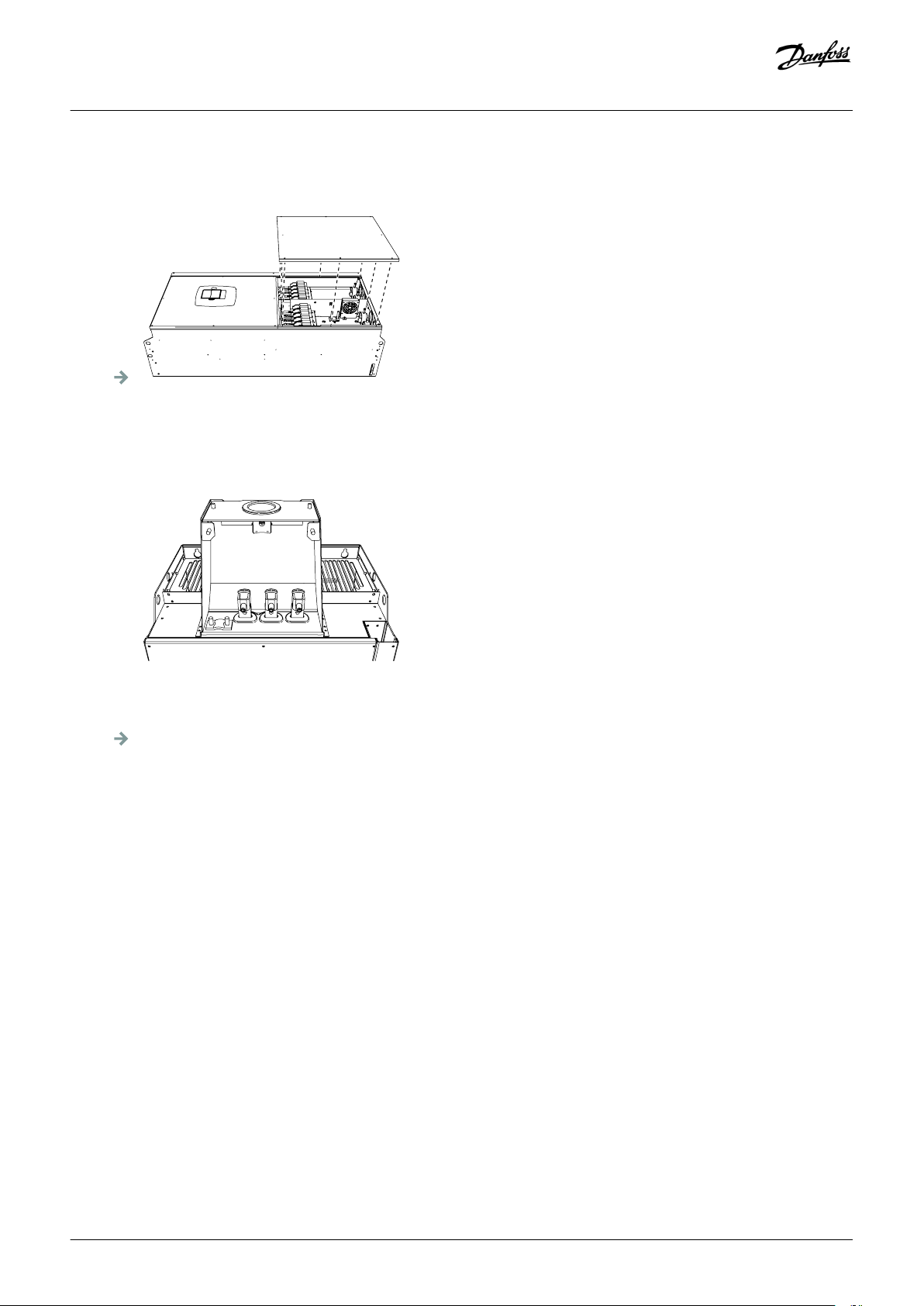
2. Open the power unit cover.
Electrical Installation
3. Find the DC terminals and Brake resistor terminals on top of the AC drive.
4. Locate the terminals.
Danfoss A/S © 2018.06
DPD00910G | 53
Page 54

FR8
e30bg102.10
A
B
C
Operating guide | VACON® NXS/NXP Air-cooled
Electrical Installation
A Control terminals
C Grounding terminals
Illustration 19: FR8 Terminals
B Motor terminals
6.4.6 Get Access and Locate the Terminals for FR9
Context:
Follow these instructions to open the AC drive for installing the cables, for example.
54 | Danfoss A/S © 2018.06
DPD00910G
Page 55
e30bg075.10
B-
B+
R+
R-
e30bg076.10
Operating guide | VACON® NXS/NXP Air-cooled
Procedure
1. Remove the cable cover.
2. Find the DC terminals and Brake resistor terminals on top of the AC drive.
Electrical Installation
3. Locate the terminals.
Danfoss A/S © 2018.06
DPD00910G | 55
Page 56

FR9
e30bg103.10
A
B
C
Operating guide | VACON® NXS/NXP Air-cooled
Electrical Installation
A Control terminals
C Grounding terminals
Illustration 20: FR9 Terminals
B Motor terminals
6.5 Installing the Cables
Context:
Use these instructions to find the installation instructions of the correct enclosure size.
Procedure
1. Check the requirements related to lengths, distances, and positioning of the cables according to instructions in 6.5.1 Additional
Instructions for Cable Installation.
2. Follow the installation instructions of the correct enclosure size. To check the enclosure size of the AC drive, see 3.5 Enclosure Sizes.
• 6.5.2 Installing the Cables, FR4-FR6
• 6.5.3 Installing the Cables, FR7
•
6.5.4 Installing the Cables, FR8
• 6.5.5 Installing the Cables, FR9
• 6.5.6 Installing the Cables, FR10-FR11
56 | Danfoss A/S © 2018.06
DPD00910G
Page 57

Operating guide | VACON® NXS/NXP Air-cooled
Electrical Installation
6.5.1 Additional Instructions for Cable Installation
• Before starting, make sure that none of the components of the AC drive is live. Read carefully the warnings in Safety section.
• Make sure that the motor cables are sufficiently far from other cables.
•
The motor cables must go across other cables at an angle of 90°.
• If it is possible, do not put the motor cables in long parallel lines with other cables.
• If the motor cables are in parallel with other cables, obey the minimum distances (see
• The distances are also valid between the motor cables and the signal cables of other systems.
•
The maximum lengths of shielded motor cables are 300 m (984 ft) (AC drives with power greater than 1.5 kW or 2 hp), and 100 m
(328 ft) (AC drives with power from 0.75 kW to 1.5 kW or 1–2 HP). If the used motor cables are longer than these, speak to the
factory to get more information.
Each parallel cable adds to the total length.
table 11).
NOTIC E
If long motor cables are used (maximum 100 m or 328 ft) together with small drives (≤1.5 kW or ≤2.01 hp), the capacitive
current in the motor cable can increase the measured motor current compared to the actual motor current. Think this when
setting up the motor stall protection functions.
• If the cable insulation checks are necessary, see 9.3 Measuring the Cable and Motor Insulation.
Table 11: Minimum Distances between Cables
The distance between cables [m]
0.3 ≤ 50 1.0 ≤ 164.0
1.0 ≤ 300 3.3 ≤ 656.1
The length of the shielded cable
[m]
The distance between cables [ft]
The length of the shielded cable
[ft]
6.5.2 Installing the Cables, FR4-FR6
Context:
Follow these instructions to install the cables and cable accessories.
For information on how to comply with the UL regulations in cable installation, see 6.1.2 UL Standards on Cabling.
If it is necessary to connect an external brake resistor, see VACON® Brake Resistor Manual. See also
Resistor Connection.
Prerequisites:
Make sure that the delivery contains all necessary components. For the installation, the contents of the accessories bag is needed, see
4.1 Checking the Delivery.
Open the covers according to instructions in 6.4.1 Get Access and Locate the Terminals for FR4, 6.4.2 Get Access and Locate the
Terminals for FR5 or 6.4.3 Get Access and Locate the Terminals for FR6.
8.7.8.2 Setting the Internal Brake
Danfoss A/S © 2018.06
DPD00910G | 57
Page 58
A
B
C
e30bg085.10
e30bg086.10
Operating guide | VACON® NXS/NXP Air-cooled
Electrical Installation
Procedure
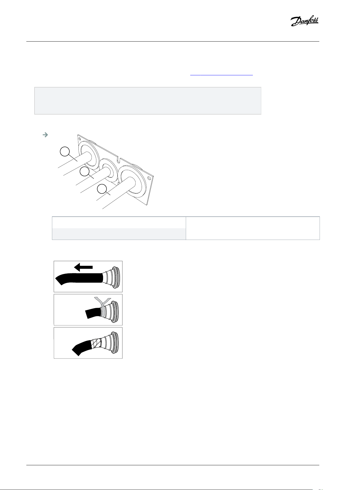
1. Strip the motor cable, the mains cable, and the brake resistor cable. See 12.4 Cable Stripping Lengths.
2. Cut the grommets open to move the cables through them. Use the grommets delivered in the accessories bag.
• Do not cut the grommet openings wider than what is necessary for the used cables.
• If the grommets fold in when putting the cable, pull the cable back to make the grommets straight.
• Use a grommet as an alternative to the grommet in types where this is necessary.
3. Put the cables - the mains cable, the motor cable, and the optional brake cable - in the openings of the cable entry plate. Use the
cable entry plate delivered in the accessories bag.
A The mains cable
B The brake cable
C The motor cable
Illustration 21: Cables through the Cable Entry Plate
4. Put the cable entry plate with the cables into the groove on the frame of the drive. To attach the cable entry plate, use the M4x10
screws delivered in the accessories bag.
58 | Danfoss A/S © 2018.06
DPD00910G
Page 59

e30bg088.10
e30bg093.10
Operating guide | VACON® NXS/NXP Air-cooled
Electrical Installation
5. Connect the cables. See the correct tightening torques in 12.6 Tightening Torques of the Terminals.
• Connect the phase conductors of the mains cable and of the motor cable, and the conductors of the brake resistor cable into
the correct terminals.
• FR4, FR5: Attach the grounding conductor of each cable to a grounding terminal with a grounding terminal for grounding
conductor. Use the grounding terminals delivered in the accessories bag.
• FR6: Attach the grounding conductor of each cable to a grounding terminal with a grounding clamp for grounding
conductor. Use the grounding clamps and the screws delivered in the accessories bag.
6. Make sure to connect the grounding conductor to the motor and the terminals that are identified with the grounding symbol.
• For FR4 and FR5: Two protective conductors are necessary to comply with the requirements of the standard IEC/EN
61800-5-1. See 6.3 Grounding.
• If a double grounding is necessary, use the grounding terminal below the drive. Use an M5 screw and tighten it to 2.0 Nm or
17.7 lb-in.
7. Attach the cable cover 12.5 Tightening Torques for Cover Screws. Attach the grounding clamps for control cable with 3 pieces of
M4x16 screws delivered in the accessories bag. Use these clamps to ground the control cables.
Danfoss A/S © 2018.06
DPD00910G | 59
Page 60

e30bg070.10
Operating guide | VACON® NXS/NXP Air-cooled
Illustration 22: FR4-FR6
Electrical Installation
8. Attach the cover of the drive. For the tightening torques of the screws, see 12.5 Tightening Torques for Cover Screws. Make sure
that the control cables or the cables of the AC drive are not caught between the frame and the cable cover.
6.5.3 Installing the Cables, FR7
Context:
Follow these instructions to install the cables and cable accessories.'
For information on how to comply with the UL regulations in cable installation, see 6.1.2 UL Standards on Cabling.
If it is necessary to connect an external brake resistor, see VACON® Brake Resistor Manual. See also 8.7.8.2 Setting the Internal Brake
Resistor Connection.
Prerequisites:
Make sure that the delivery contains all necessary components. For the installation, the contents of the accessories bag is needed, see
4.1 Checking the Delivery.
Open the covers according to instructions in 6.4.4 Get Access and Locate the Terminals for FR7.
60 | Danfoss A/S © 2018.06
DPD00910G
Page 61

A
B
C
e30bg085.10
e30bg086.10
Operating guide | VACON® NXS/NXP Air-cooled
Electrical Installation
Procedure
1. Strip the motor cable, the mains cable, and the brake resistor cable. See 12.4 Cable Stripping Lengths.
2. Cut the grommets open to move the cables through them. Use the grommets delivered in the accessories bag.
• Do not cut the grommet openings wider than what is necessary for the used cables.
• If the grommets fold in when putting the cable, pull the cable back to make the grommets straight.
• Use a grommet as an alternative to the grommet in types where this is necessary.
3. Put the cables - the mains cable, the motor cable, and the optional brake cable - in the openings of the cable entry plate. Use the
cable entry plate delivered in the accessories bag.
A The mains cable
B The brake cable
C The motor cable
Illustration 23: Cables through the Cable Entry Plate
4. Put the cable entry plate with the cables into the groove on the frame of the drive. To attach the cable entry plate, use the M4x10
screws delivered in the accessories bag.
Danfoss A/S © 2018.06
DPD00910G | 61
Page 62
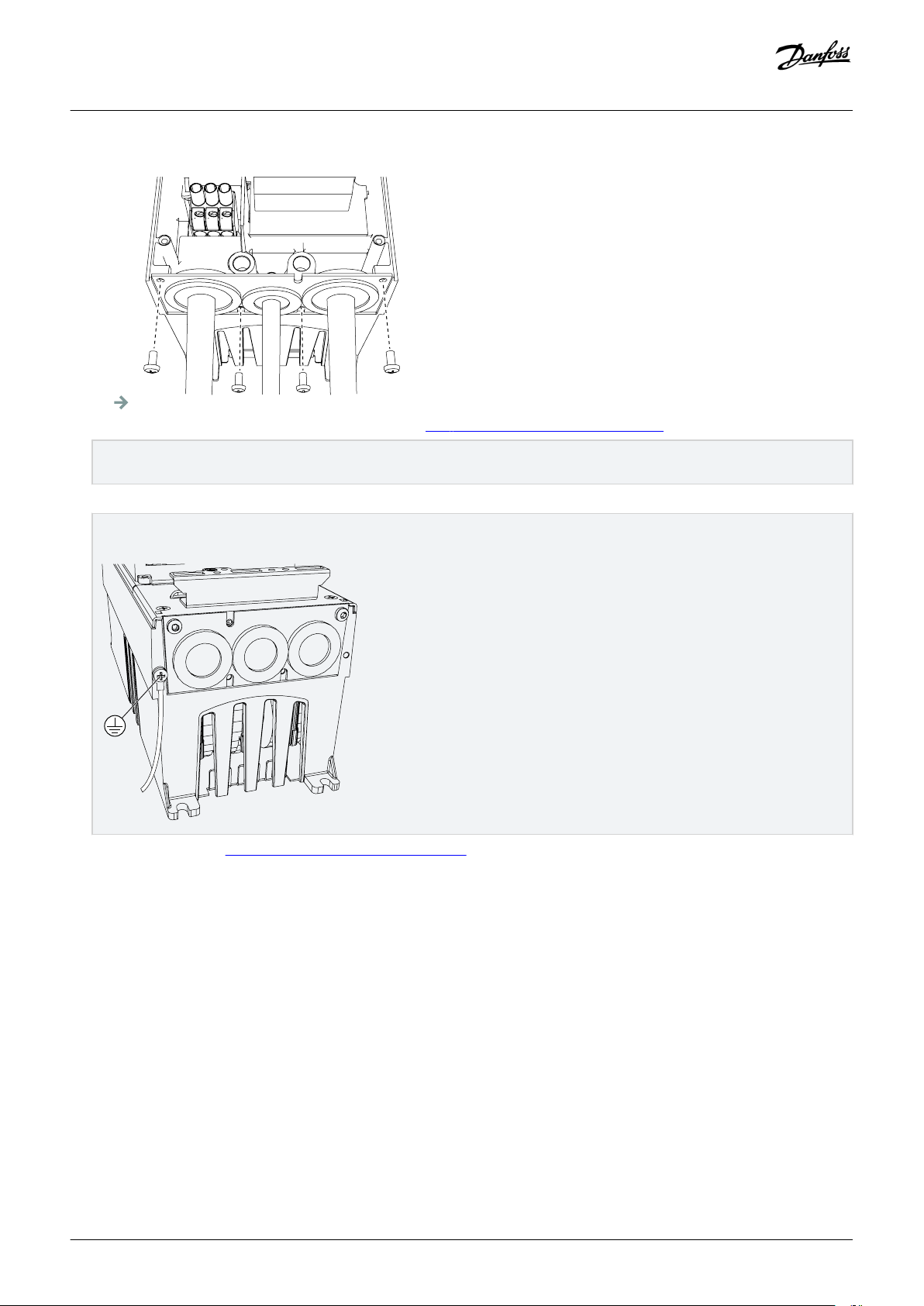
e30bg088.10
e30bg093.10
Operating guide | VACON® NXS/NXP Air-cooled
Electrical Installation
5. Connect the cables. See the correct tightening torques in 12.6 Tightening Torques of the Terminals.
• Connect the phase conductors of the mains cable and of the motor cable, and the conductors of the brake resistor cable into
the correct terminals.
6. Make sure to connect the grounding conductor to the motor and the terminals that are identified with the grounding symbol.
• If a double grounding is necessary, use the grounding terminal below the drive. Use an M5 screw and tighten it to 2.0 Nm or
17.7 lb-in.
7. Attach the cable cover 12.5 Tightening Torques for Cover Screws. Attach the grounding clamps for control cable with 3 pieces of
M4x16 screws delivered in the accessories bag. Use these clamps to ground the control cables.
62 | Danfoss A/S © 2018.06
DPD00910G
Page 63

1
2
e30bg073.10
Operating guide | VACON® NXS/NXP Air-cooled
Electrical Installation
1 Standard 2 PROFIBUS
Illustration 24: FR7
8. Attach the cover of the drive. For the tightening torques of the screws, see 12.5 Tightening Torques for Cover Screws. Make sure
that the control cables or the cables of the AC drive are not caught between the frame and the cable cover.
6.5.4 Installing the Cables, FR8
Context:
Follow these instructions to install the cables and cable accessories.
For information on how to comply with the UL regulations in cable installations, see 6.1.2 UL Standards on Cabling.
If it is necessary to connect an external brake resistor, see VACON® Brake Resistor Manual. See also 8.7.8.2 Setting the Internal Brake
Resistor Connection.
Danfoss A/S © 2018.06
DPD00910G | 63
Page 64

Operating guide | VACON® NXS/NXP Air-cooled
Prerequisites:
Make sure that the delivery contains all necessary components. For the installation, the contents of the accessories bag is needed, see
4.1 Checking the Delivery.
Open the covers according to instructions in 6.4.5 Get Access and Locate the Terminals for FR8.
Electrical Installation
64 | Danfoss A/S © 2018.06
DPD00910G
Page 65

e30bg077.10
Operating guide | VACON® NXS/NXP Air-cooled
Electrical Installation
Procedure
1. Strip the motor cable, the mains cable, and the brake resistor cable. See 12.4 Cable Stripping Lengths
2. To move the cables through the grommets, cut them open. Use the grommets delivered in the accessories bag.
• Do not cut the grommet openings wider than what is necessary for the used cables.
• If the grommets fold in when putting the cable, pull the cable back to make the grommets straight.
• Use a grommet as an alternative to the grommet in types where it is necessary.
3. Attach the grommet and the cable until the frame of the drive goes into the groove of the grommet.
• With the protection rating IP54 (UL Type 12), the connection between the grommet and the cable must be tight. Pull the first
bit of the cable out of the grommet until it stays straight.
• If it is not possible, make the connection tight with some insulation tape or a cable tie.
4. Connect the cables. See the correct tightening torques in 12.6 Tightening Torques of the Terminals.
• Connect the phase conductors of the mains cable and of the motor cable into the correct terminals. If a brake resistor cable is
used, connect its conductors into the correct terminals.
• Attach the grounding conductor of each cable to a grounding terminal with a grounding clamp for grounding conductor.
5. To make a 360° connection with the grounding clamp for cable shield, expose the shield of all cables.
6. Attach the cable entry plate, and then the cable cover. For the tightening torques of the screws, see 12.5 Tightening Torques for
Cover Screws. Make sure that the control cables or the cables of the AC drive are not caught between the frame and the cable
cover.
Additional tightening torques:
• motor cable entry plate: 2.4 Nm
•
control cable entry plate: 0.8 Nm
• DC cover: 2.4 Nm
7. Attach the grounding clamps for control cable on the grounding level with M4x16 screws. Use the clamps delivered in the
accessories bag. Use the clamps to ground the control cables.
Danfoss A/S © 2018.06
DPD00910G | 65
Page 66

1
2
e30bg074.10
Operating guide | VACON® NXS/NXP Air-cooled
Electrical Installation
1 Standard 2 PROFIBUS
8. Attach the cover of the drive. For the tightening torques of the screws, see 12.5 Tightening Torques for Cover Screws.
Illustration 25: FR8
6.5.5 Installing the Cables, FR9
Context:
Follow these instructions to install the cables.
For information on how to comply with the UL regulations in cable installations, see 6.1.2 UL Standards on Cabling.
If it is necessary to connect an external brake resistor, see VACON® Brake Resistor Manual. See also 8.7.8.2 Setting the Internal Brake
Resistor Connection.
Prerequisites:
Make sure that the delivery contains all necessary components.
Open the covers according to instructions in 6.4.6 Get Access and Locate the Terminals for FR9.
66 | Danfoss A/S © 2018.06
DPD00910G
Page 67

e30bg077.10
Operating guide | VACON® NXS/NXP Air-cooled
Electrical Installation
Procedure
1. Strip the motor cable, the mains cable, and the brake resistor cable. See 12.4 Cable Stripping Lengths
2. To move the cables through grommets, cut the them open.
• Do not cut the grommet openings wider than what is necessary for the used cables.
•
If the grommets fold in when putting the cable, pull the cable back to make the grommets straight.
• Use a grommet as an alternative to the grommet in types where this is necessary.
3. Attach the grommet and the cable until the frame of the drive goes into the groove of the grommet.
• With the protection rating IP54 (UL Type 12), the connection between the grommet and the cable must be tight. Pull the first
bit of the cable out of the grommet until it stays straight.
• If this is not possible, make the connection tight with some insulation tape or a cable tie.
4. Connect the cables. See the correct tightening torques in 12.6 Tightening Torques of the Terminals.
• Connect the phase conductors of the mains cable and of the motor cable into the correct terminals. If a brake resistor cable is
used, connect its conductors into the correct terminals.
• Attach the grounding conductor of each cable to a grounding terminal with a grounding clamp for grounding conductor.
5. Expose the shield of all cables to make a 360° connection with the grounding clamp for cable shield.
Danfoss A/S © 2018.06
DPD00910G | 67
Page 68

e30bg104.10
Operating guide | VACON® NXS/NXP Air-cooled
6. Attach the cable entry plate, and then the cable cover. For the tightening torques of the screws, see 12.5 Tightening Torques for
Cover Screws. Make sure that the control cables or the cables of the AC drive are not caught between the frame and the cable
cover.
Electrical Installation
6.5.6 Installing the Cables, FR10-FR11
For more information on how to install the cables for enclosure sizes FR10 and larger, see VACON® NXP/C User Manual.
6.6 Installation in an IT System
If mains is impedance-grounded (IT), the AC drive must have the EMC protection level C4. If the drive has the EMC protection level C2,
it is necessary to change it to C4. To do this, remove the EMC jumpers.
For equivalents of EMC levels in VACON® AC drives, see 3.4 Description of the Type Code.
WARN I N G
SHOCK HAZARD FROM THE COMPONENTS
The components of the drive are live when the drive is connected to mains.
Do not make changes in the AC drive when it is connected to mains.
-
NOTIC E
DAMAGE TO THE AC DRIVE FROM INCORRECT EMC LEVEL
The EMC level requirements for the AC drive depend on the installation environment. An incorrect EMC level can damage the
drive.
Before connecting the AC drive to the mains, make sure that the EMC level of the AC drive is correct for the mains.
-
68 | Danfoss A/S © 2018.06
DPD00910G
Page 69

Operating guide | VACON® NXS/NXP Air-cooled
Electrical Installation
6.6.1 Installing the AC drive in an IT System, FR4-FR6
Context:
Use these instructions to change the EMC protection of the AC drive to level C4.
Prerequisites:
Open the cover of the AC drive and remove the cable cover as instructed in 6.4.1 Get Access and Locate the Terminals for FR4, 6.4.2 Get
Access and Locate the Terminals for FR5 or 6.4.3 Get Access and Locate the Terminals for FR6.
Danfoss A/S © 2018.06
DPD00910G | 69
Page 70
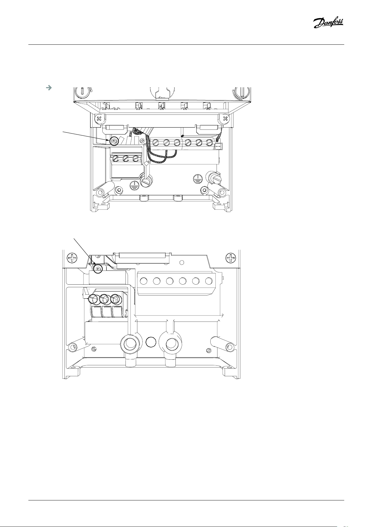
FR4
e30bg094.10
FR5
e30bg095.10
Operating guide | VACON® NXS/NXP Air-cooled
Procedure
1. Remove the EMC screw(s).
Electrical Installation
Illustration 26: FR4
Illustration 27: FR5
70 | Danfoss A/S © 2018.06
DPD00910G
Page 71

FR6
e30bg096.10
e30bg472.10
Operating guide | VACON® NXS/NXP Air-cooled
Electrical Installation
Illustration 28: FR6
2. For FR4, remove the control unit.
There is a sticker next to the terminals to remind to remove the jumper X10-1 if the AC drive requires this. If there is no sticker,
move to step 4.
3. Remove the jumper X10-1.
Danfoss A/S © 2018.06
DPD00910G | 71
Page 72

e30bg473.10
Operating guide | VACON® NXS/NXP Air-cooled
Electrical Installation
4. Close the cover of the AC drive. For the tightening torques of the screws, see 12.5 Tightening Torques for Cover Screws.
5. After the change, put a check mark to "EMC Level modified" and write the date on the "product modified" label (see 4.4 Using the
Product Modified Label). If the label is not yet attached, attach it on the drive near the nameplate.
6.6.2 Installing the AC Drive in an IT System, FR7
Context:
Use these instructions to change the EMC protection of the AC drive to level C4.
Prerequisites:
Open the cover and the cable cover of the AC drive as instructed in 6.4.4 Get Access and Locate the Terminals for FR7.
72 | Danfoss A/S © 2018.06
DPD00910G
Page 73

e30bg097.10
e30bg098.10
Operating guide | VACON® NXS/NXP Air-cooled
Procedure
1. Open the power unit cover of the AC drive.
2. Remove the EMC screws.
Electrical Installation
3. Remove the screw and replace with a plastic screw M4.
Danfoss A/S © 2018.06
DPD00910G | 73
Page 74
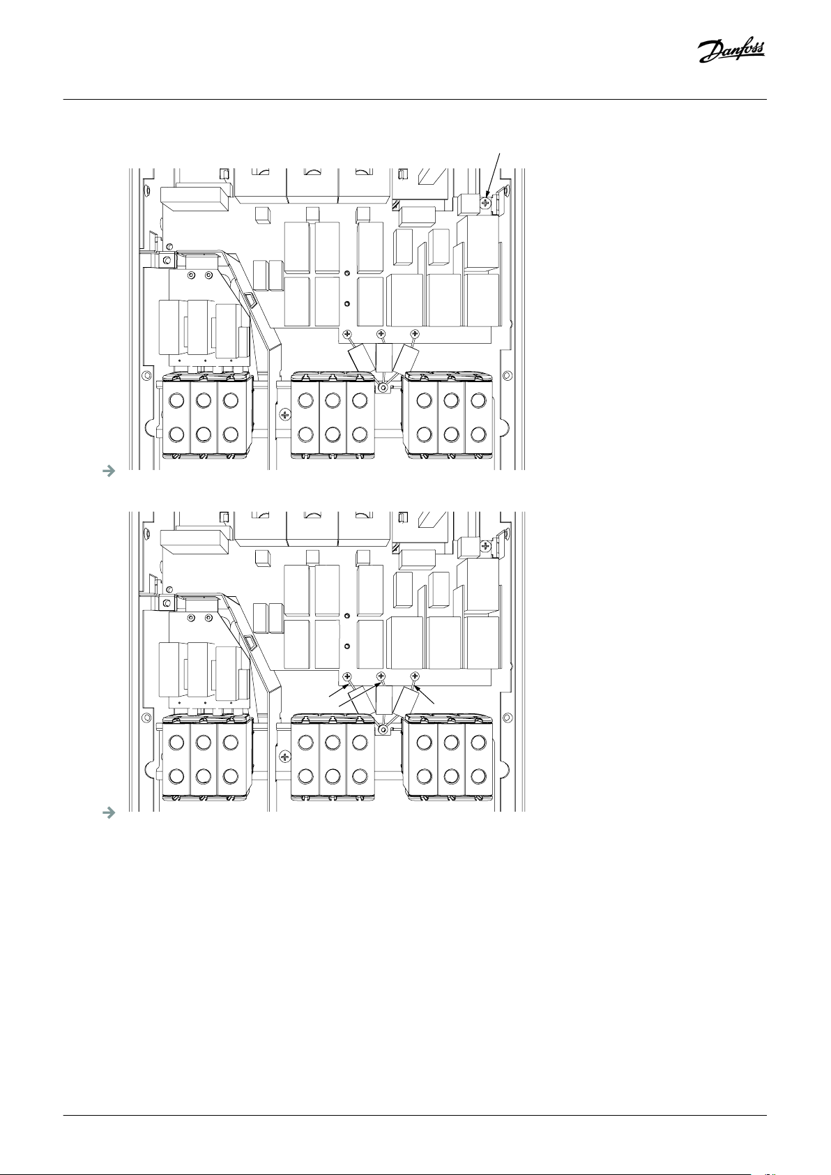
e30bg099.10
e30gb100.10
Operating guide | VACON® NXS/NXP Air-cooled
Electrical Installation
4. Cut the leads of the 3 capacitors.
5. Remove the screw and the capacitor assembly.
74 | Danfoss A/S © 2018.06
DPD00910G
Page 75
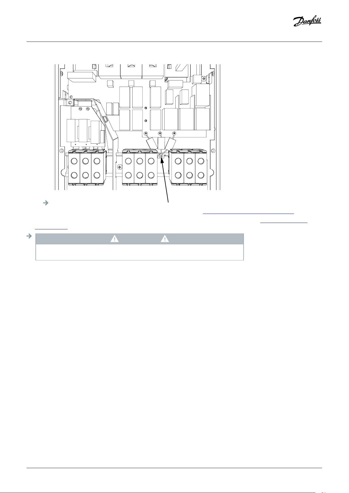
e30bg101.10
Operating guide | VACON® NXS/NXP Air-cooled
Electrical Installation
6. Close the cover of the AC drive. For the tightening torques of the screws, see 12.5 Tightening Torques for Cover Screws.
7. After the change, write "The EMC level was changed" and the date on the "product changed" label (see 4.4 Using the Product
Modified Label). If the label is not yet attached, attach it on the drive near the nameplate.
NOTIC E
Only an authorized VACON® service person can change the EMC level of FR7 back to C2.
6.6.3 Installing the AC Drive in an IT System, FR8-FR11
Only a VACON® service person can change the EMC protection class of VACON® NXS/NXP, FR8-FR11.
Danfoss A/S © 2018.06
DPD00910G | 75
Page 76

A
B
C
D
E
e30bf997.10
Operating guide | VACON® NXS/NXP Air-cooled
Control Unit
7 Control Unit
7.1 Control Unit Components
The control unit of the AC drive contains the control board and additional boards (see illustration 29) connected to the 5 slot
connectors (A to E) of the control board. The control board is connected to the power unit through a D-connector or fiber optic cables
(FR9).
Illustration 29: Basic and Option Slots on the Control Board
The control unit of the delivered AC drive contains the standard control interface. If the order included special options, the AC drive is
delivered according to the order. The next pages contain information on the terminals and general wiring examples. The type code
shows the I/O boards that are installed at the factory. For more information on the option boards, see VACON® NX I/O Boards User
manual.
The OPTA1 basic board has 20 control terminals, and the relay board has 6 or 7. The standard connections of the control unit and the
descriptions of signals are shown in
For instructions on how to install the control unit that is not attached to the power unit, see VACON® NXP IP00 Drives Installation
Manual.
7.3.2 Control Terminals on OPTA1.
7.2 Control Voltage (+24V/EXT +24V)
It is possible to use the drive with an external power source with these properties: +24 V DC ±10%, minimum 1000 mA. Use it to
externally power up the control board, and the basic and option boards. The analog outputs and inputs at OPTA1 do not work with
only +24 V supplied to the control unit.
Connect the external power source to one of the 2 bidirectional terminals (#6 or #12), see the option board manual or VACON® NX I/O
Boards User Manual. With this voltage, the control unit stays on and parameters can be set. The measurements of the main circuit (for
example, the DC-link voltage, and the unit temperature) are not available when the drive is not connected to mains.
76 | Danfoss A/S © 2018.06
DPD00910G
Page 77
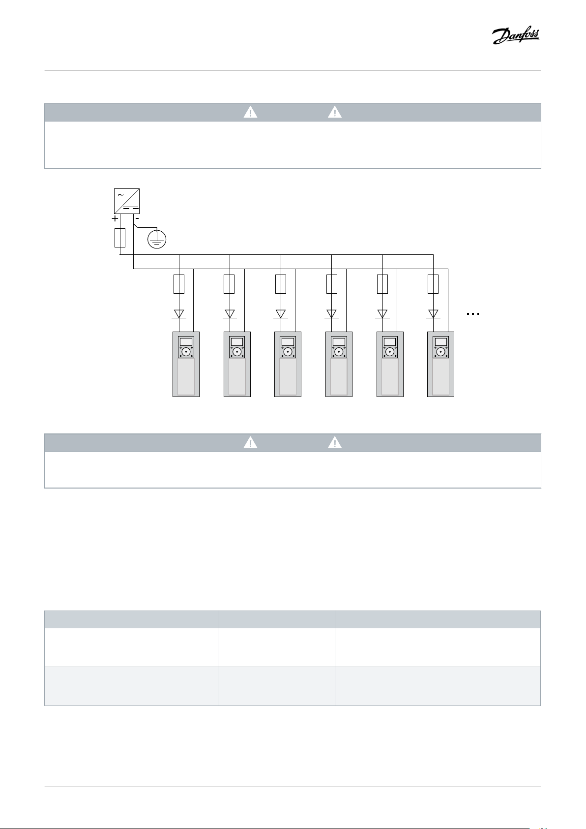
e30bg012.10
PE/GND
-G1
Ext +24VDC
Power Supply
-F1
#6 #7 #6 #7 #6 #7 #6 #7 #6 #7 #6 #7
-F2
1A
gG/
Class CC
-Q1
3A
-Q2
3A
-Q3
3A
-Q4
3A
-Q5
3A
-Q6
3A
-F3
1A
gG/
Class CC
-F4
1A
gG/
Class CC
-F5
1A
gG/
Class CC
-F6
1A
gG/
Class CC
-F7
1A
gG/
Class CC
Operating guide | VACON® NXS/NXP Air-cooled
Control Unit
NOTIC E
If the AC drive is supplies with external 24 V DC power, use a diode in terminal #6 (or #12) to prevent the current to flow in
opposite direction. Put a 1 A fuse in 24 V DC line for each AC drive. The maximum current consumption of each drive is 1 A from
the external supply.
Illustration 30: Parallel Connection of 24 V Inputs with Many AC Drives
7.3 Control Unit Cabling
7.3.1 Selection of the Control Cables
The control cables must be a minimum of 0.5 mm2 (20 AWG) shielded multicore cables. See more on the cable types in table 10. The
terminal wires must be a maximum of 2.5 mm2 (14 AWG) for the terminals of the relay board and 1.5 mm2 (16 AWG) for other terminals.
Table 12: Tightening Torques of the Control Cables
NOTIC E
The control unit I/O ground is not isolated from the chassis ground/protective earth. In the installation, consider the potential
differences between the grounding points. We recommend using galvanic isolation in the I/O and 24 V circuitry.
The terminal The terminal screw The tightening torque in Nm (lb-in.)
Relay and thermistor terminals M3 0.5
(4.5)
Other terminals M2.6 0.2
(1.8)
Danfoss A/S © 2018.06
DPD00910G | 77
Page 78

e30bg013.10
1
6
2
3
4
5
18
19
20
12
7
13
8
9
10
14
15
16
11
17
Maximum current 10 mA
Differential input if not connected to ground
Allows ±20 V common mode voltage to GND
Ground for reference and controls
Same as terminal #7
Digital inputs can be disconnected from ground (*)
Must be connected to GND or 24 V of I/O term.
or to ext.24 V or GND
Selection with jumper block X3 (*)
Ri = min. 5 kΩ
18-30 V = 1
Ri = min. 5 kΩ
18-30 V = 1
Output signal range: Current 0(4)-20 mA,
RL max 500 Ω or
Voltage 0-10 V, RL >1kΩ
Selection with jumper block X6 (*)
Maximum Uin = 48 VDC
Maximum current = 50 mA
Open collector output
AO1-
DO1
+24V
GND
GND
DIN1
DIN2
DIN3
DIN4
DIN5
DIN6
CMA
CMB
Standard I/O board
Terminal Signal Description
+10V
ref
AI1+
GND/AI1-
AI2+
GND/AI2-
+24V
Reference voltage
Analogue input,
voltage or current
Analogue input,
voltage or current
24 V aux. voltage
I/O ground
Analogue input common
Analogue input common
Common A for DIN1—DIN3
Common B for DIN4-DIN6
Analogue signal (+output)
Analogue output common
Control voltage output
I/O ground
AO1+
Selection V/mA with jumper block X1 (*)
0...+10 V (Ri = 200 kΩ)
(-10V...+10V Joystick ctrl, sel. with jumper)
0-20 mA (Ri =250 Ω)
Differential input if not connected to ground
Allows ±20 V common mode voltage to GND
Selection V/mA with jumper block X1 (*)
0...+10 V (Ri = 200 kΩ)
(-10V...+10V Joystick ctrl, sel. with jumper)
0-20 mA (Ri =250 Ω)
±15%, max. 250 mA (all boards total)
150 mA (from single board)
Can also be used as external power back-up for
the control unit (and fieldbus)
Same as terminal #6
Digital input 1
Digital input 4
Digital input 5
Digital input 6
Digital input 2
Digital input 3
Reference potentiometer,
1-10kΩ
Operating guide | VACON® NXS/NXP Air-cooled
Control Unit
7.3.2 Control Terminals on OPTA1
The figure shows the basic description of the terminals of the I/O board. For more information, see 7.3.2.2 Jumper Selections on the
OPTA1 Basic Board. For more information on control terminals, see VACON® All in One Application manual.
*) See figure in 7.3.2.2 Jumper Selections on the OPTA1 Basic Board
Illustration 31: Control Terminal Signals on OPTA1
Parameter references for I/O on control panel and NCDrive are: An.IN:A.1, An.IN:A.2, DigIN:A.1, DigIN:A.2, DigIN:A.3, DigIN:A.4, DigIN:A.5,
DigIN:A.6, AnOUT:A.1 and DigOUT:A.1.
To use the control voltage output +24 V/EXT+24 V:
• wire the +24 V control voltage to digital inputs through an external switch. OR
use the control voltage to power up external equipment, such as encoders and auxiliary relays.
•
The specified total load on all available +24 V/EXT+24 V output terminals must not exceed 250 mA.
78 | Danfoss A/S © 2018.06
DPD00910G
Page 79
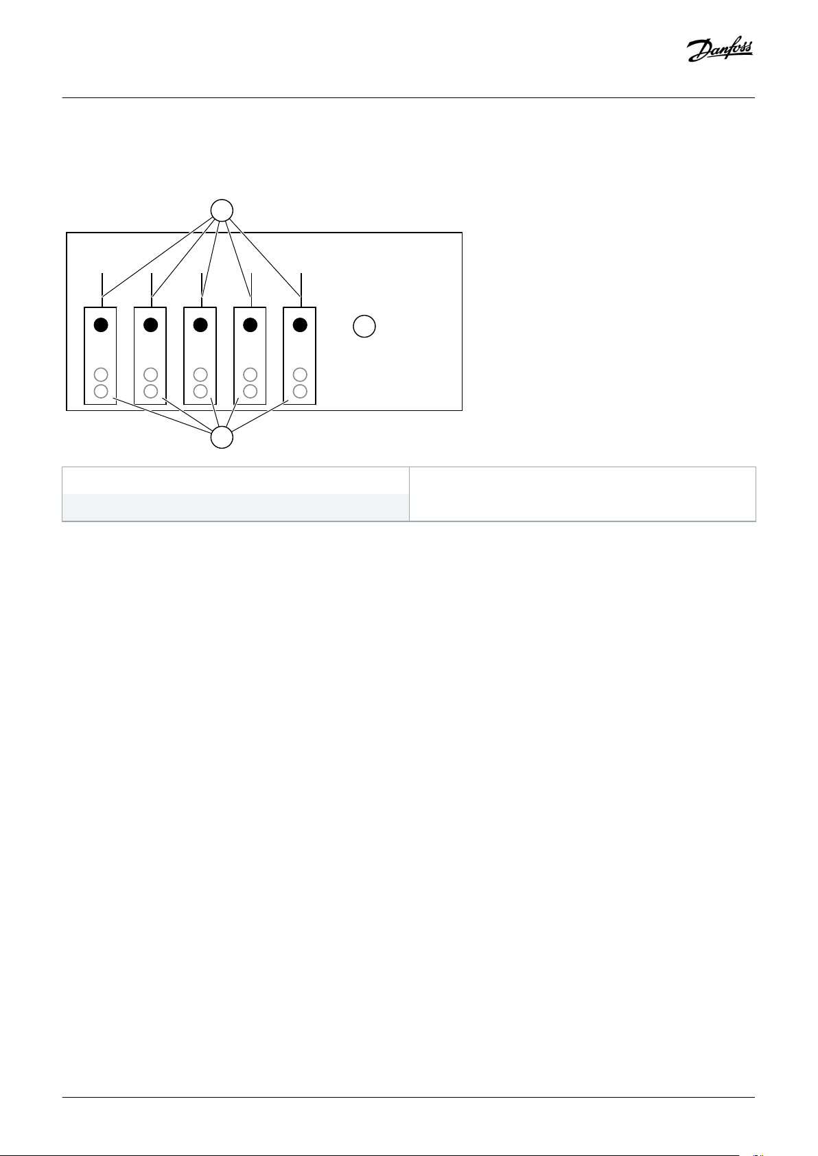
=
A
B
C
e30bg014.10
Operating guide | VACON® NXS/NXP Air-cooled
The maximum load on the +24 V/EXT+24 V output per board is 150 mA. If there is a +24 V/EXT+24 V output on the board, it is locally
short circuit protected. If one of the +24 V/ EXT+24 V outputs short circuits, the others remain powered because of the local protection.
Control Unit
A Maximum 150 mA
C Maximum 250 mA
Illustration 32: Maximum Loads on +24 V/EXT+24 V Output
B +24 V out
7.3.2.1 Digital Input Signal Inversions
The active signal level is different when the common inputs CMA and CMB (terminals 11 and 17) are connected to +24 V or to ground
(0 V).
The 24 V control voltage and the ground for the digital inputs and the common inputs (CMA, CMB) can be internal or external.
Danfoss A/S © 2018.06
DPD00910G | 79
Page 80

A B
e30bg015.10
DIN1
+24V
GND
DIN2
DIN3
CMA
+24V
GND
DIN1
DIN2
DIN3
CMA
X6
X2
X1
X3
e30bg016.10
X6
X2
X1
ABCDABC
D
ABC
D
X3
Operating guide | VACON® NXS/NXP Air-cooled
Control Unit
A Positive logic (+24 V is the active signal) = the input is active
when the switch is closed.
B Negative logic (0 V is the active signal) = the input is active
when the switch is closed. Set the jumper X3 to the position
'CMA/CMB isolated from ground'.
Illustration 33: Positive/Negative Logic
7.3.2.2 Jumper Selections on the OPTA1 Basic Board
The functions of the AC drive can be changed to make them better agree with local requirements. To do this, change some positions
for the jumpers on the OPTA1 board. The positions of the jumpers set the signal type of analog and digital inputs. Changing the AI/AO
signal contents requires also a change in the related board parameter in menu M7.
On the A1 basic board, there are 4 jumper blocks: X1, X2, X3, and X6. Each jumper block contains 8 pins and 2 jumpers. See the possible
jumper selections in illustration 34.
Illustration 34: Jumper Blocks on OPTA1
80 | Danfoss A/S © 2018.06
DPD00910G
Page 81
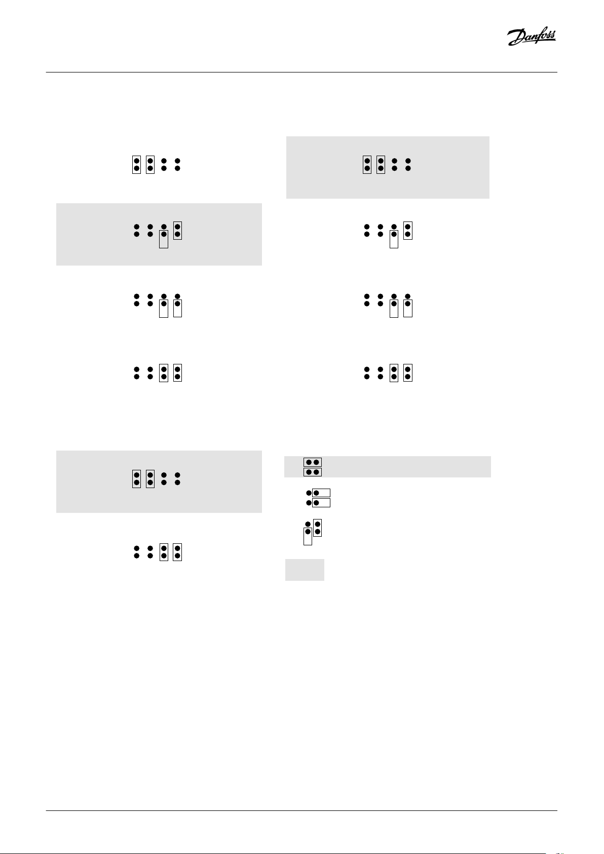
e30bg017.10
A B C D
A B C D
A B C D
A B C D
A B C D
A B C D
Jumper block X1:
AI1 mode
AI1 mode: 0...20mA; Current input
Jumper block X2:
AI2 mode
= Factory default
A B C D
AI1 mode: 0...20mA; Current input
Jumper block X6:
AO1 mode
AO1 mode: 0....20mA; Current output
AO1 mode: Voltage output; 0...10V
AI1 mode: Voltage input; 0...10V AI2 mode:Voltage input; 0...10V
A B C D
AI1 mode: Voltage input; 0...10V
differential
AI2 mode: Voltage input; 0...10V
differential
A B C D
AI1 mode: Voltage input; -0...10V AI2 mode: Voltage input; -10...10V
A B C D
Jumper block X3:
CMA and CMB grounding
CMB connected to GND
CMA connected to GND
CMB isolated from GND
CMA isolated from GND
CMB and CMA
internally connected together,
isolated from GND
Operating guide | VACON® NXS/NXP Air-cooled
Control Unit
Illustration 35: Jumper Selections for OPTA1
7.3.3 Control Terminals on OPTA2 and OPTA3
Danfoss A/S © 2018.06
DPD00910G | 81
Page 82

DigOUT:B.1 *)
DigOUT:B.2 *)
DigOUT:B.1 *)
DigOUT:B.2 *)
DigIN:B.1 *)
e30bg018.10
21
OPTA2
22
23
24
25
26
RO1/1
RO1/2
RO1/3
RO2/1
RO2/2
RO2/3
Relay output 1
Relay output 2
Switching capacity
• 24 VDC/8 A
• 250 VAC/8 A
• 125 VDC/0.4 A
Minimum switching load
• 5 V/10 mA
Switching capacity
• 24 VDC/8 A
• 250 VAC/8 A
• 125 VDC/0.4 A
Minimum switching load
• 5 V/10 mA
Switching capacity
• 24 VDC/8 A
• 250 VAC/8 A
• 125 VDC/0.4 A
Minimum switching load
• 5 V/10 mA
Switching capacity
• 24 VDC/8 A
• 250 VAC/8 A
• 125 VDC/0.4 A
Minimum switching load
• 5 V/10 mA
21
OPTA3
22
23
25
26
28
RO1/1
RO1/2
RO1/3
RO2/1
RO2/2
TI1+
29 TI1-
Relay output 1
Relay output 2
Thermistor input
e30bg019.10
X1
X2
21
22
23
24
25
26
Operating guide | VACON® NXS/NXP Air-cooled
Control Unit
*) Parameter reference on control panel and NCDrive.
Illustration 36: Control Terminal Signals on Relay Boards OPTA2 and OPTA3
Illustration 37: OPTA2
82 | Danfoss A/S © 2018.06
DPD00910G
Page 83

e30bg020.10
21
22
23
25
26
28
29
X1
X2
X3
Operating guide | VACON® NXS/NXP Air-cooled
Illustration 38: OPTA3
7.4 Installation of Option Boards
For information on how to install the option boards, see the option board manual or VACON® NX I/O Boards User Manual.
Control Unit
7.5 Galvanic Isolation Barriers
The control connections are isolated from mains. The GND terminals are permanently connected to I/O ground. See
The digital inputs on the I/O board are galvanically isolated from the I/O ground. The relay outputs are also double-isolated from each
other at 300 VAC (EN-50178).
illustration 39.
Danfoss A/S © 2018.06
DPD00910G | 83
Page 84

e30bg021.10
10V
ref
L1
L2 L3
U
V
W
GND
AI1
GND
Control I/O
ground
Gate drivers
Control
panel
Control
unit
Power unit
Digital
input
group A
Digital
input
group B
Analogue
input
Digital
input
+24V
AI2-
AI2+
AO2-
DO1
AO1+
DIN3
CMA
DIN1...
DIN6
CMB
DIN4...
RO1/2
RO1/3
RI1/1
RO2/2
RO2/3
TI1+
TI1-
RO2/1
Operating guide | VACON® NXS/NXP Air-cooled
Control Unit
Illustration 39: Galvanic Isolation Barriers
84 | Danfoss A/S © 2018.06
DPD00910G
Page 85
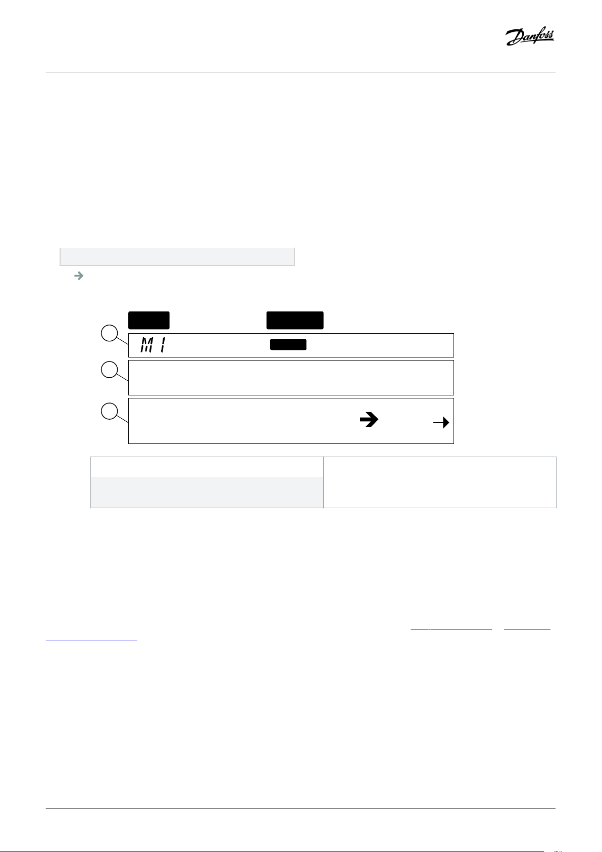
READY
RUN
Keypad
A
B
C
e30bf980.10
Monitor
V1
V1
Operating guide | VACON® NXS/NXP Air-cooled
Using the Control Panel
8 Using the Control Panel
8.1 Navigating on the Control Panel
Context:
The data of the AC drive is in menus and submenus. Follow these instructions to navigate in the menu structure on the control panel.
Procedure
1. To move between the menus, use the Browser buttons Up and Down on the keypad.
2. To go into a group or an item, push the Menu button Right.
To go back to the previous level, push the Menu button Left.
The display shows the current location in the menu, for example S6.3.2. The display also shows the name of the group or
item in the current location.
A The location on the menu
C The number of items that are available or the item
value.
Illustration 40: Navigation Items on the Control Panel
B The description (name of the page)
8.2 Using the Monitoring Menu (M1)
Context:
Follow these instructions to monitor the actual values of the parameters and signals.
The values cannot be changed in the Monitoring menu. To change the values of parameters, see 8.3.2 Selecting Values or 8.3.3 Editing
the Values Digit by Digit.
Danfoss A/S © 2018.06
DPD00910G | 85
Page 86

e30bg022.10
READY
RUN
Monitor
Keypad
V1 V14
Operating guide | VACON® NXS/NXP Air-cooled
Procedure
1. To find the Monitoring menu, scroll down in the main menu until the location indication M1 shows on the first line of the display.
2. To go to the Monitoring menu from the main menu, push the Menu button Right.
3. To scroll through the menu, push the Browser buttons Up and Down.
Using the Control Panel
8.2.1 Monitored Values
The monitored values have the indication V#.#. The values update each 0.3 s.
86 | Danfoss A/S © 2018.06
DPD00910G
Page 87

Operating guide | VACON® NXS/NXP Air-cooled
Using the Control Panel
Index Monitored value Unit ID Description
V1.1 Output frequency Hz 1 The output frequency to the motor
V1.2 Frequency reference Hz 25 The frequency reference to motor control
V1.3 Motor speed rpm 2 The actual speed of the motor in rpm
V1.4 Motor current A 3 Measured motor current
V1.5 Motor torque % 4 The calculated shaft torque
V1.6 Motor power % 5 The calculated motor shaft power in percentage
V1.7 Motor voltage V 6 The output voltage to the motor
V1.8 DC link voltage V 7 The measured voltage in the DC-link of the drive
V1.9 Unit temperature °C 8 The heat sink temperature in Celsius or Fahrenheit
V1.10 Motor temperature % 9 The calculated motor temperature in percentage of the nominal temperature. See
VACON® All in One Application Manual.
V1.11 Analog input 1 V/mA 13
V1.12 Analog input 2 V/mA 14
AI1
AI2
(1)
(1)
V1.13 DIN 1, 2, 3 15 Shows the status of the digital inputs 1-3
V1.14 DIN 4, 5, 6 16 Shows the status of the digital inputs 4-6
V1.15 DO1, RO1, RO2 17 Shows the status of the digital and relay outputs 1-3
V1.16 Analog I
out
V1.17 Multimonitoring items Shows 3 monitored values to select from. See
mA 26 AO1
8.7.6.9 Enabling/Disabling the Change
of Multimonitoring Items.
1
If the AC drive only has +24 V supply (for control board power-up), this value is not reliable.
See VACON® All in One Application Manual for more monitored values.
8.3 Using the Parameter Menu (M2)
8.3.1 Finding the Parameter
Context:
Use these instructions to find the parameter to edit.
Danfoss A/S © 2018.06
DPD00910G | 87
Page 88

READY
G1
Keypad
G8
e30bg023.10
Parameters
READY
Keypad
G1 G8
e30bg024.10
Input signals
READY
Keypad
P1
P18
e30bg025.10
Input signals
READY
Keypad
e30bg026.10
Min Frequency
13.95 Hz
Operating guide | VACON® NXS/NXP Air-cooled
Procedure
1. To find the Parameter menu, scroll down in the main menu until the location indication M2 shows on the first line of the display.
2. Push the Menu button Right to move into the Parameter Group Menu (G#).
Using the Control Panel
3. To find the parameter group, use the Browser buttons Up and Down.
4. Use the Browser buttons Up and Down to find the parameter (P#) to edit. To move directly from the last parameter of a parameter
group to the first parameter of that group, push the Browser button Up.
8.3.2 Selecting Values
Context:
Use these instructions to edit the text values on the control panel.
The basic application package "All in One+" includes 7 applications with different sets of parameters. For more information, see
VACON® All in One Application Manual.
88 | Danfoss A/S © 2018.06
DPD00910G
Page 89

READY
Keypad
e30bg026.10
Min Frequency
13.95 Hz
READY
Keypad
e30bg028.10
Min Frequency
13.95 Hz
READY
Keypad
e30bg029.10
Min Frequency
14.45 Hz
Operating guide | VACON® NXS/NXP Air-cooled
Prerequisites:
When the drive is in RUN state, many parameters are locked, and cannot be edited. Only the text Locked shows on the display. Stop the
AC drive to edit these parameters.
Procedure
1. Use the Browser buttons Up and Down to find the parameter (P#) to edit. To move directly from the last parameter of a parameter
group to the first parameter of that group, push the Browser button Up.
2. To go to the Edit mode, push the Menu button Right. The parameter value starts to blink.
Using the Control Panel
3. Set the new value with the Browser buttons Up and Down.
4. To accept the change, push the [enter] button or ignore the change with menu button Left.
If the [enter] button is pushed, the value stops to blink and the new value shows in the value field.
5. For locking the parameter values, use the Parameter Lock function in menu M6, see 8.7.6.6 Locking a Parameter.
8.3.3 Editing the Values Digit by Digit
Context:
Use these instructions to edit the numerical values on the control panel.
The basic application package "All in One+" includes 7 applications with different sets of parameters. For more information, see
VACON® All in One Application Manual.
Prerequisites:
Danfoss A/S © 2018.06
DPD00910G | 89
Page 90
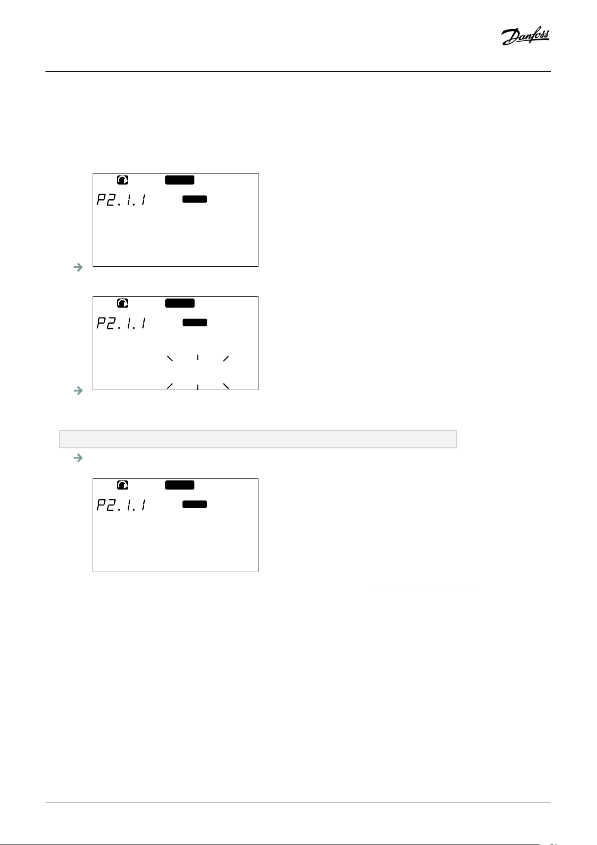
READY
Keypad
e30bg026.10
Min Frequency
13.95 Hz
READY
Keypad
e30bg028.10
Min Frequency
13.95 Hz
READY
Keypad
e30bg029.10
Min Frequency
14.45 Hz
Operating guide | VACON® NXS/NXP Air-cooled
When the drive is in RUN state, many parameters are locked, and cannot be edited. Only the text Locked shows on the display. Stop the
AC drive to edit these parameters.
Procedure
1. Find the parameter with the Browser and Menu buttons.
2. To go to the Edit mode, push the Menu button Right. The parameter value starts to blink.
Using the Control Panel
3. Push the Menu button Right. The value can now be edited digit by digit.
4. To accept the change, push the [enter] button.
To ignore the change, push Menu button Left many times, until the view goes back to the parameter list.
If the [enter] button is pushed, the value stops to blink and the new value shows in the value field.
5. For locking the parameter values, use the Parameter Lock function in menu M6, see 8.7.6.6 Locking a Parameter.
8.4 Using the Keypad Control Menu
8.4.1 Finding the Keypad Control Menu
Context:
In the Keypad control menu, the following functions are available: selecting the control mode, editing the frequency reference, and
changing the direction of the motor.
90 | Danfoss A/S © 2018.06
DPD00910G
Page 91

READY
STOP
I/O term
P1
P4
e30bg033.10
Keypad control
I/O term
Keypad
Bus/Comm
Operating guide | VACON® NXS/NXP Air-cooled
Procedure
1. To find the Keypad control menu, scroll down in the main menu until the location indication M3 shows on the first line of the
display.
2. To go to the Keypad control menu from the main menu, push the Menu button Right.
Using the Control Panel
8.4.2 Keypad Control Parameters M3
Table 13: Keypad Control Parameters, M3
Index Parameter Min Max Unit Default Cust ID Description
P3.1 Control place 1 3 1 125 The control mode
1 = I/0 terminal
2 = Keypad (control panel)
3 = Fieldbus
R3.2 Keypad reference P2.1.1 P2.1.2 Hz 0.00 123 0 = Forward
1 = Reverse
P3.3 Direction (on keypad) 0 1 0
P3.4 Stop button 0 1 1 114 0 = Limited function of Stop button
1 = Stop button always enabled
8.4.3 Changing the Control Mode
Context:
3 control modes are available to control the AC drive. For each control place, a different symbol shows on the display:
The control mode The symbol
I/O terminals
Keypad (control panel)
Fieldbus
Danfoss A/S © 2018.06
DPD00910G | 91
Page 92

READY
STOP
I/O term
e30bg034.10
Control Place
I/O Terminal
Operating guide | VACON® NXS/NXP Air-cooled
Procedure
1. In the Keypad control menu (M3), find the control mode (Control Place) with Menu buttons Up and Down.
2. To go to the edit mode, push the Menu button Right.
The parameter value starts to blink.
3. To scroll through the options, push the Browser buttons Up and Down.
4. To select the control mode, push the [enter] button.
Using the Control Panel
8.4.4 Keypad Reference
The keypad reference submenu (P3.2) shows the frequency reference. In this submenu, also the frequency reference can be edited.
8.4.4.1 Editing the Frequency Reference
Context:
Use these instructions to change the frequency reference.
Procedure
1. In the Keypad control menu (M3), find the Keypad reference with Menu buttons Up and Down.
2. To go to the edit mode, push the Menu button Right. The frequency reference value starts to blink.
3. Set the new value with the Browser buttons.
The value changes only on the control panel.
4. To make the motor speed to agree with the value on the control panel, select the keypad as the control mode, see 8.4.3 Changing
the Control Mode.
8.4.5 Changing the Rotation Direction
Context:
The keypad direction submenu shows the rotation direction of the motor. In this submenu, also the rotation direction can be changed.
For more information on how to control the motor with the control panel, see 3.8.2 Keypad and 9.2 Commissioning the AC Drive.
92 | Danfoss A/S © 2018.06
DPD00910G
Page 93

Operating guide | VACON® NXS/NXP Air-cooled
Procedure
1. In the Keypad control menu (M3), find the Keypad direction with the Menu buttons Up and Down.
2. To go to the edit mode, push the Menu button Right.
3. Select the direction with Menu buttons Up and Down.
The rotation direction changes on the control panel.
4. To make the motor to agree with the set rotation direction, select the keypad as the control mode, see 8.4.3 Changing the Control
Mode.
Using the Control Panel
8.4.6 Disabling the Stop Motor Function
Context:
As a default, the motor stops when the Stop button is pushed no matter what is the control mode. Use these instructions to disable
this function.
Procedure
1. In the Keypad control menu (M3), find the page 3.4. Stop button with the Browser buttons.
2. To go to the edit mode, push the Menu button Right.
3. To select Yes or No, use the Browser buttons.
4. Accept the selection with the [enter] button.
When the Stop motor function is not active, the Stop button stops the motor only when the keypad is the control mode.
8.4.7 Special Functions in Keypad Control Menu
8.4.7.1 Selecting the Keypad as the Control Mode
Context:
This is a special function only available in menu M3.
Prerequisites:
Make sure to be in the menu M3 and control mode is other than keypad.
Procedure
1. Do one of the following options:
Keep the Start button pushed down for 3 s when the motor is in RUN state.
Keep the Stop button pushed down for 3 s when the motor is stopped.
In other menu than M3, when the keypad is not the active control mode and the start button is pushed, an error message Keypad
Control NOT ACTIVE shows. In some applications this error message is not shown.
The keypad is selected as the control mode and the current frequency reference and direction is copied to the control
panel.
Danfoss A/S © 2018.06
DPD00910G | 93
Page 94

Operating guide | VACON® NXS/NXP Air-cooled
Using the Control Panel
8.4.7.2 Copying the Frequency Reference Set to the Control Panel
Context:
These are special functions only available in menu M3.
Use these instructions to copy the frequency reference set from I/O or fieldbus to control panel.
Prerequisites:
Make sure to be in menu M3 and that the control mode is other than keypad.
Procedure
1. Keep the [enter] button pushed down for 3 s.
In other menu than M3, when the keypad is not the active control mode and the start button is pushed, an error message Keypad
Control NOT ACTIVE shows.
8.5 Using the Active Faults Menu (M4)
8.5.1 Finding the Active Faults Menu
Context:
The Active faults menu shows a list of active faults. When there are no active faults, the menu is empty.
For more information on the fault types and how to reset faults, see 11.1 General Information on Fault Tracing and 11.2 Resetting a
Fault. For the fault codes, possible causes and information on how to correct the fault, see 12.10 Fault Codes.
94 | Danfoss A/S © 2018.06
DPD00910G
Page 95
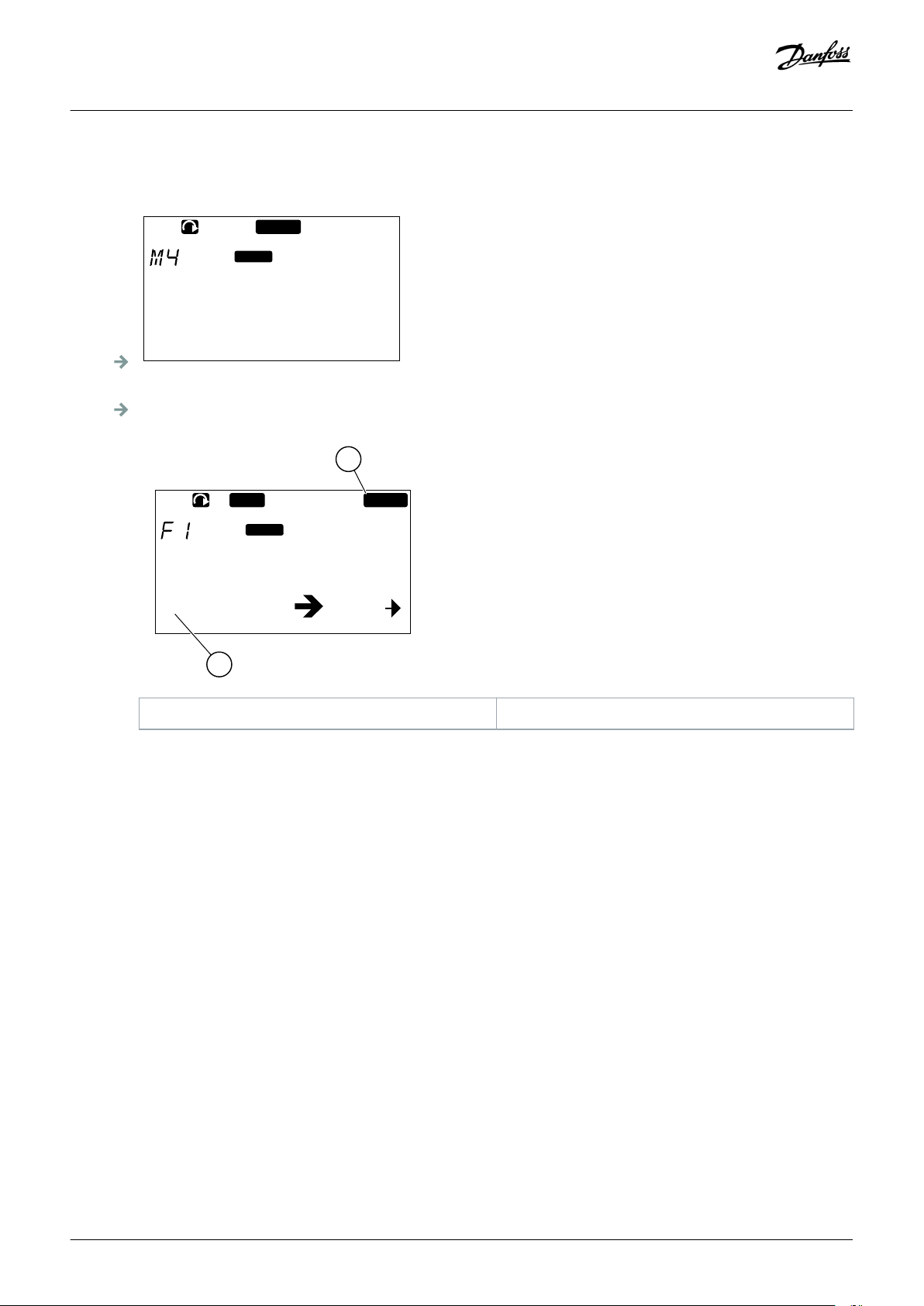
READY
I/O term
F0
e30bg035.10
Active faults
T1 T13
F
STOP
I/O term
FAULT
B
A
e30bg036.10
11 Output phase
Operating guide | VACON® NXS/NXP Air-cooled
Procedure
1. To find the Active faults menu, scroll down in the main menu until the location indication M4 shows on the first line of the display.
2. To go to the Active faults menu from the main menu, push the Menu button Right.
If there is a fault in the display, these symbols show:
Using the Control Panel
A Fault symbol B Fault type symbol
Illustration 41: Fault Symbols
8.5.2 Examining the Fault Time Data Record
Context:
This menu shows some important data that was valid at the time of the fault. This helps to find the cause of the fault.
Procedure
1. Find the fault in Active faults menu or Fault history menu.
2. Push the Menu button Right.
3. Scroll the data T.1-T.16 with the Browser buttons.
8.5.3 Fault Time Data Record
The fault time data record shows some important data that was valid at the time of the fault. This helps to find the cause of the fault.
If real time is set on the AC drive, the data items T1 and T2 show as in column Real Time Data Record.
Danfoss A/S © 2018.06
DPD00910G | 95
Page 96

Operating guide | VACON® NXS/NXP Air-cooled
Using the Control Panel
In some special cases, some of the fields can show other data than described in the table. If the value of a field differs significantly from
the expected value, this special usage can be the reason. Contact the nearest distributor to get help from the factory in understanding
the data.
Code Description Value Real Time Data Record
T.1 Counted operation days d yyyy-mm-dd
T.2 Counted operation hours hh:mm:ss (d) hh:mm:ss,sss
T.3 Output frequency Hz (hh:mm:ss)
T.4 Motor current A
T.5 Motor voltage V
T.6 Motor power %
T.7 Motor torque %
T.8 DC voltage V
T.9 Unit temperature °C
T.10 Run status
T.11 Direction
T.12 Warnings
T.13
0-speed
(1)
T.14 Subcode
T.15 Module
T.16 Submodule
1
Tells if the drive was at zero speed (< 0.01 Hz) when the fault showed.
8.6 Using the Fault History Menu (M5)
8.6.1 Fault History Menu (M5)
There is a maximum number of 30 faults in the Fault history. The information on each fault shows in the Fault time data record, see
8.5.3 Fault Time Data Record.
The value line of the main page (H1->H#) shows the number of faults in the fault history. The location indication tells in which order
the faults have shown. The newest fault has the indication H5.1, the second newest H5.2, and so on. If there are 30 faults in the history,
the next fault that shows removes the oldest one (H5.30) from the history.
See the different fault codes in 12.10 Fault Codes.
96 | Danfoss A/S © 2018.06
DPD00910G
Page 97

READY
I/O term
S1
S11
e30bg037.10
System Menu
Operating guide | VACON® NXS/NXP Air-cooled
Using the Control Panel
8.6.2 Resetting the Fault History
Context:
The Fault History shows 30 latest faults at a time. Use these instructions to reset the history.
Procedure
1. To find the Fault history menu, scroll down in the main menu until the location indication M5 shows on the first line of the display.
2. To go to the Fault history menu from the main menu, push the Menu button Right.
3. In the Fault history menu, push the [enter] button for 3 s.
The symbol H# changes to 0.
8.7 Using the System Menu (M6)
8.7.1 Finding the System Menu
Context:
The System menu includes the general settings of the AC drive. These are, for example, application selection, parameter sets and
information about the hardware and software. The number of submenus and subpages shows as the symbol S# (or P#) on the value
line.
Procedure
1. To find the System menu, scroll down in the main menu until the location indication M6 shows on the first line of the display.
2. To go to the System menu from the main menu, push the Menu button Right.
8.7.2 System Menu Functions
Table 14: System Menu Functions
Code Function Min Max Unit Default Cust Description
S6.1 Language selection English The selection is different in
all the language packages
Danfoss A/S © 2018.06
DPD00910G | 97
Page 98

Operating guide | VACON® NXS/NXP Air-cooled
Code Function Min Max Unit Default Cust Description
Using the Control Panel
S6.2 Application selection Basic applica-
tion
S6.3 Copy parameters
S6.3.1 Parameter sets Store set 1
S6.3.2 Load up to keypad All parameters
Basic application
Standard application
Local/Remote control appl.
Multi-Step application
PID Control application
Multi-Purpose Control appl.
Pump and Fan Control
appl.
Load set 1
Store set 2
Load set 2
Load factory defaults
S6.3.3 Load down from keypad All parameters
All but motor parameters
Application parameters
P6.3.4 Parameter back-up Yes Yes
No
S6.4 Compare parameters
S6.4.1 Set1 Not used
S6.4.2 Set 2 Not used
S6.4.3 Factory settings
S6.4.4 Keypad set
S6.5 Security
S6.5.1 Password Not used 0 = Not used
P6.5.2 Parameter lock Change Ena-
bled
S6.5.3 Start-up wizard No
Change Enabled
Change Disabled
Yes
98 | Danfoss A/S © 2018.06
DPD00910G
Page 99

Operating guide | VACON® NXS/NXP Air-cooled
Code Function Min Max Unit Default Cust Description
S6.5.4 Multimonitoring items Change Enabled
S6.6 Keypad settings
P6.6.1 Default page
P6.6.2 Default page/ Operating
menu
P6.6.3 Timeout time 0 65535 s 30
P6.6.4 Contrast 0 31 18
P6.6.5 Backlight time Always 65535 min 10
S6.7 Hardware settings
P6.7.1 Internal brake resistor Connected Not connected
P6.7.2 Fan control Continuous Continuous
Using the Control Panel
Change Disabled
Connected
Temperature
First start
Calc temp
P6.7.3 HMI acknowledg. timeout 200 5000 ms 200
P6.7.4 HMI number of retries 1 10 5
P6.7.5 Sine filter Connected Not connected
Connected
S6.8 System information
S6.8.1 Total counters
C6.8.1.1 MWh counter kWh
C6.8.1.2 Power On day counter
C6.8.1.3 Power On hours counter hh:mm: ss
S6.8.2 Trip counters
T6.8.2.1 MWh counter kWh
T6.8.2.2 Clear MWh trip counter
T6.8.2.3 Operating days trip counter
T6.8.2.4 Operating hours trip counter hh:mm: ss
T6.8.2.5 Clear operating time counter
S6.8.3 Software info
S6.8.3.1 Software package
S6.8.3.2 System software version
Danfoss A/S © 2018.06
DPD00910G | 99
Page 100
Operating guide | VACON® NXS/NXP Air-cooled
Code Function Min Max Unit Default Cust Description
S6.8.3.4 System load
S6.8.4 Applications
S6.8.4.# Name of application
D6.8.4.#. 1 Application ID
D6.8.4.#. 2 Applications: Version
D6.8.4.#. 3 Applications: Firmware inter-
face
S6.8.5 Hardware
I6.8.5.1 Info: Power unit type code
I6.8.5.2 Info: Unit voltage V
I6.8.5.3 Info: Brake chopper
I6.8.5.4 Info: Brake resistor
S6.8.6 Expander boards
Using the Control Panel
S6.8.7 Debug menu For Application program-
ming only. Speak to the factory to get instructions.
8.7.3 Changing the Language
Context:
Use these instructions to change the language of the control panel. The possible languages are different in all language packages.
Procedure
1. In the System menu (M6), find the Language selection page (S6.1) with the Browser buttons.
2. To go to the edit mode, push the Menu button Right.
The name of the language starts to blink.
3. To select the language for the control panel texts, use the Menu buttons Up and Down.
4. To accept the selection, push the [enter] button.
The name of the languages stops to blink and all text information on the control panel shows in the selected language.
8.7.4 Changing the Application
Context:
The application can be changed in the Application selection page (S6.2). When the application is changed, all parameters are reset.
For more information on the Application Package, see VACON® NX All in One Application Manual.
100 | Danfoss A/S © 2018.06
DPD00910G
 Loading...