

Page 1

vacon® nxs/p
ac drives
flange mounting kit
for fr4-fr6
installation manual
Page 2

Page 3

Document code: DPD01899A
Date: 20.9.2016
INDEX
General 2
1.
2. Vacon Flange Mounting Kit contents 3
2.1 FR4 (Type designation code: THR-FR4) 3
2.2 FR5 (Type designation code: THR-FR5) 4
2.3 FR6 (Type designation code: THR-FR6) 4
3. Installation 5
4. Information sticker 8
Local contacts: http://drives.danfoss.com/danfoss-drives/local-contacts/
Page 4
2 • vacon General
1. General
Using the Vacon Flange Mounting Kit, you can mount your Vacon NX AC drive through the cabinet wall
so that the control unit of the drive remains inside the cabinet.
The correct installation of the Flange Mounting Kit affects the IP protection class of the AC drive.
After the installation, the control unit is protected according to IP21 and the power unit according to
IP54 (unless the AC drive was originally IP21-protected). See figure below.
Cabinet
IP54
IP21
According to standard IEC 60529 (EN 60529), the IP54 AC drive enclosure provides protection against
dust and water sprayed from all directions. Limited ingress of both is permitted.
1
Local contacts: http://drives.danfoss.com/danfoss-drives/local-contacts/
Page 5

vacon • 3
2. Vacon Flange Mounting Kit contents
The contents of the Flange Mounting Kits for different frames are shown in the following pictures.
2.1 FR4 (Type designation code: THR-FR4)
1 Flange, top
2 Flange, bottom
3 Fan & protection plate
4 Plastic sealing
5 Screws (4*16)
6 Screws (4*10)
7 Sealing tape
Local contacts: http://drives.danfoss.com/danfoss-drives/local-contacts/
2
Page 6

4 • vacon Vacon Flange Mounting Kit contents
2.2 FR5 (Type designation code: THR-FR5)
1 Flange, top
2 Flange, bottom
3 Fan & protection plate
2.3 FR6 (Type designation code: THR-FR6)
4 Screws (4*16)
5 Rubber sealing
6 Sealing tape
2
1 Flange, top
2 Flange, bottom
3 Fan
4 Rubber sealings
5 Cable ties
6 Screws (6*12)
7 Adhesive backed mounts
8 Sealing tape
Local contacts: http://drives.danfoss.com/danfoss-drives/local-contacts/
Page 7

vacon • 5
3. Installation
These instructions guide you through the installation of the Flange Mounting Kit that you have
purchased for your FR4, FR5 or FR6 size AC drive. Please note the white triangles in the lower left
corners of the installation pictures. They designate the frame(s) the picture applies to. If no triangles
exist, the step is applicable to all frames.
1. Open the control cable cover
and remove the cable entry flange.
4. Place the cable entry flange be-
tween the frame and the bottom
flange. Now tighten the screws.
2. Detach the protection plate.
Keep the plate and the screws to
hand, they will still be needed.
FR5
FR4
3. Attach the bottom flange to its place
with screws. Do not tighten the screws
yet.
FR4
5. Detach the fan. 6a. Insert the plastic sealing (#4).
FR5
FR5
6b. Insert the rubber sealings (#5). 7. Fix the top flange to its place.
Local contacts: http://drives.danfoss.com/danfoss-drives/local-contacts/
FR4
8. Attach the protection plate with
fan (#3) with the screws you set
aside at step 2.
3
Page 8

6 • vacon Installation
FR5
FR4
9. Detach the grounding rack from
the protection plate you removed at
step 2 and fix it to the plate with fan
using the screws from the old rack.
FR6
11. Seal the air inlets with the
rubber sealings (#4). Leave the
opening uncovered.
FR5 FR6
10a. Remove the plastic cover of
the AC drive and open the small lid
on the power unit cover. Leave the
opening uncovered.
FR6
12. Fix the lid with fan (#3) on the
power unit cover using the screws
set aside at step 10b.
10b. Remove the plastic cover of
the AC drive and open the small lid
on the power unit cover. Set the
screws aside for later use.
FR5
FR4
13. Carefully re-install the fan en-
suring that the connector clip fits
accurately. Do not slam, do not
force!
FR6
14. Attach the adhesive-backed
mounts (#7) as shown in the picture
and use the ties (#5) to fix the cables
on the power unit.
Continues on next page
*
Or any other free 24Vout terminal on your available I/O
3
15. Connect the fan cables to termi-
nals #6 (red) and #7 (black) of the
basic I/O board (NXOPTA1 or
NXOPTA8)
*
Local contacts: http://drives.danfoss.com/danfoss-drives/local-contacts/
Page 9

vacon • 7
16. Apply the sealing tape attached around the opening along the edge. Place the tape so that it runs
inside
the screw holes.
The kit contains a greater amount of tape than what you might need. Only use such an amount of
tape required by the dimensions of the opening. See Figure 1.
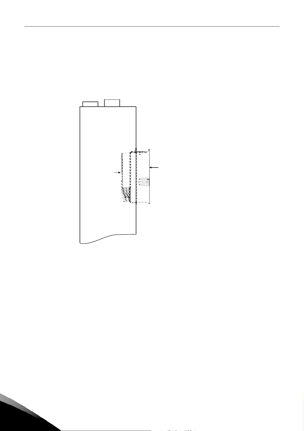
17. Fit the AC drive in the opening.
NOTE: The AC drive will not fit in the opening in a straight position. Tip the converter positioning
the lower end first in the opening. See Figures 2 and 3.
Sealing
tape
Figure 1.
Figures 2 and 3.
Local contacts: http://drives.danfoss.com/danfoss-drives/local-contacts/
3
Page 10

8 • vacon Information sticker
4. Information sticker
Each Flange Mounting Kit delivered by the factory includes a sticker (shown below).
Please check
IP54/Collar
(1) and mark the installation date (2) on the sticker. Finally, attach the
sticker on the drive.
1
Op tion board:
in slot:
IP54 upgr a de/ C ol l ar
EMC level modified: H to T / T to H
Dri ve mod ified
NXOPT................
A B C D E
:
Date:...................
Date:...................
Date:...................
2
4
Local contacts: http://drives.danfoss.com/danfoss-drives/local-contacts/
Page 11

www.danfoss.com
Vacon Ltd
Member of the Danfoss Group
Runsorintie 7
65380 Vaasa
Finland
Document ID:
DPD01899A
Rev. A
 Loading...