

Danfoss VACON NXS Installation guide
VACON® NXS/P AC DRIVES
QUICK GUIDE
GUIDE RAPIDE
KURZANLEITUNG
GUIDA RAPIDA
GUÍA RÁPIDA
GUIA RÁPIDO
快速指南
PIKAOPAS
EN
FR
DE
IT
ES
PTBR
ZH
FI


TOC
COOLING / REFROIDISSEMENT / KÜHLUNG / RAFFREDDAMENTO /
REFRIGERACIÓN / REFRIGERAÇÃO / 冷却 / JÄÄHDYTYS ................................4
CABLE INSTALLATION / INSTALLATION DES CÂBLES / KABELINSTALLATION /
INSTALLAZIONE DEI CAVI / INSTALACIÓN DE LOS CABLES /
INSTALAÇÃO DO CABO / 电缆安装 / KAAPELIEN ASENNUS .........................5
CONTROL PANEL AND KEYPAD ........................................................................6
EN
CONTROL TERMINALS ......................................................................................7
BASIC MENU STRUCTURE ................................................................................8
FIRST STARTUP ...............................................................................................9
PANNEAU OPÉRATEUR ...................................................................................10
FR
BORNES DE COMMANDE ................................................................................11
STRUCTURE DE MENU DE BASE ...................................................................12
PREMIÈRE MISE EN SERVICE ........................................................................13
STEUERTAFEL UND TASTENFELD ..................................................................14
DE
STEUERANSCHLÜSSE .....................................................................................15
BASISMENÜSTRUKTUR ................................................................................16
ERSTES ANLAUFEN ........................................................................................17
PANNELLO DI CONTROLLO E PANNELLO DI COMANDO ...............................18
IT
MORSETTI DI CONTROLLO ..............................................................................19
STRUTTURA DI BASE DEI MENU ....................................................................20
PRIMO AVVIO ...................................................................................................21
CUADRO DE CONTROL Y PANEL .....................................................................22
ES
TERMINALES DE CONTROL ............................................................................23
ESTRUCTURA BÁSICA DE MENÚS .................................................................24
PRIMERA PUESTA EN MARCHA .....................................................................25
PT-
PAINEL DE CONTROLE E TECLADO ................................................................26
BR
TERMINAIS DE CONTROLE .............................................................................27
ESTRUTURA BÁSICA DO MENU .....................................................................28
PRIMEIRA INICIALIZAÇÃO ..............................................................................29
控制面板和键盘 ................................................................................................30
ZH
控制端子 ...........................................................................................................31
基本菜单结构 ...................................................................................................32
首次启动 ...........................................................................................................33
OHJAUSPANEELI .............................................................................................34
FI
OHJAUSLIITTIMET ...........................................................................................35
PERUSVALIKKORAKENNE ..............................................................................36
ENSIMMÄINEN KÄYNNISTYS..........................................................................37
DISPOSAL / MISE AU REBUT / ENTSORGUNG / SMALTIMENTO /
ELIMINACIÓN / DESCARTE / 处置 / HÄVITTÄMINEN ....................................... 38
3
COOLING / REFROIDISSEMENT / KÜHLUNG / RAFFREDDAMENTO /
EN
REFRIGERACIÓN / REFRIGERAÇÃO / 冷却 / JÄÄHDYTYS
FR
DE
IT
ES
PTBR
ZH
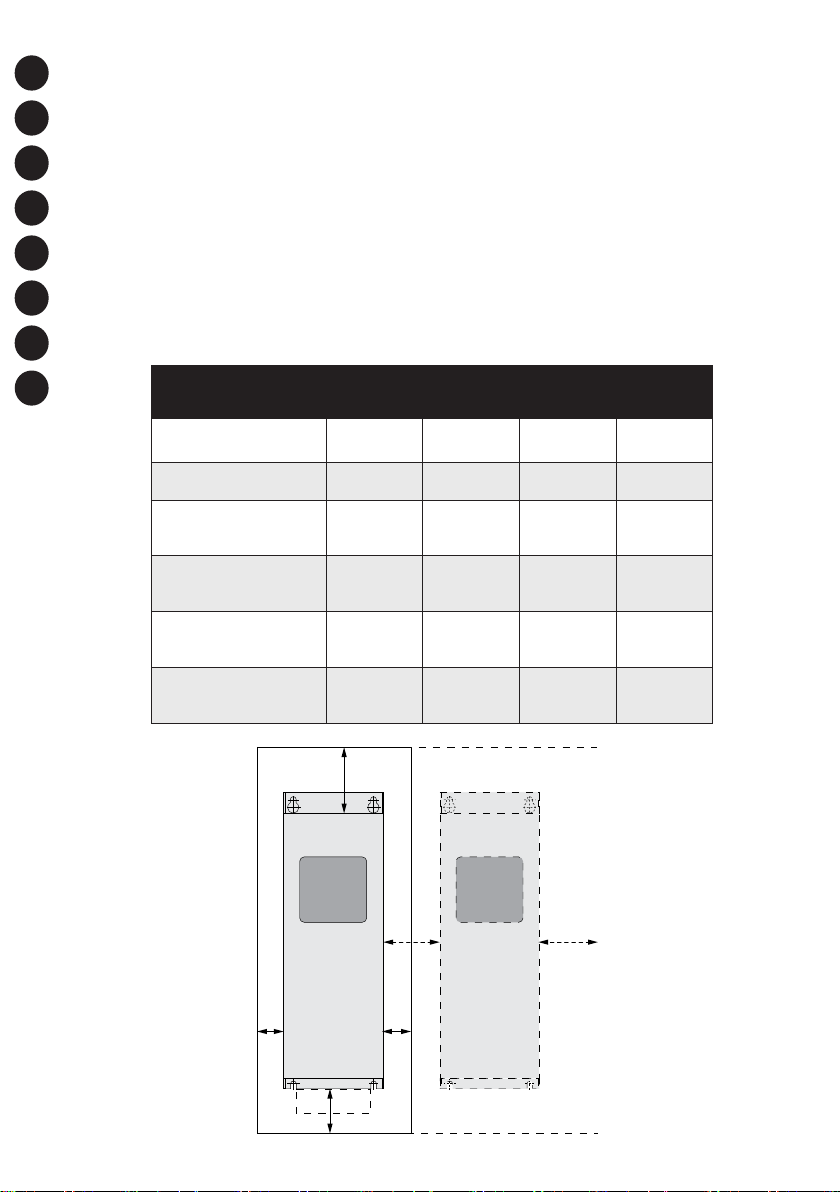
The minimum clearance around the drive
Dégagement minimal autour du convertisseur
Mindestabstand um den Umrichter herum
Distanza minima intorno all’inverter
La separación mínima alrededor del convertidor
Espaço livre mínimo ao redor do conversor
变频器周围的最小间隙
Vähimmäisilmavälit taajuusmuuttajan ympärillä
FI
Drive type
0003 2-0012
20003 5-0012 5
0017 2-0031
20016 5-0031 5
0048 2-0061
20038 5-0061
50004 6-0034 6
0075 2-0114
20072 5-0105
50041 6-0052 6
0140 2-0205
20140 5-0205
50062 6-0100 6
0261 2-0300
20261 5-0300
50125 6-0208 6
A B C D
mm (in)
20
(0.79)
20
(0.79)
30
(1.18)
80
(3.15)
80
(3.15)
50
(1.97)
C
20
(0.79)
20
(0.79)
20
(0.79)
80
(3.15)
80
(3.15)
80
(3.15)
100
(3.94)
120
(4.72)
160
(6.30)
300
(11.81)
300
(11.81)
400
(15.75)
B B
50
(1.97)
60
(2.36)
80
(3.15)
100
(3.94)
200
(7.87)
250
(9.84)
A
A
2
A
A
2
D
4
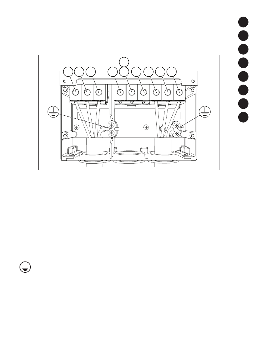
CABLE INSTALLATION / INSTALLATION DES CÂBLES /
KABELINSTALLATION / INSTALLAZIONE DEI CAVI /
INSTALACIÓN DE LOS CABLES / INSTALAÇÃO DO CABO /
电缆安装 / KAAPELIEN ASENNUS
L1 L2 L3 B- R+B+R- U V W
Example: FR6
LI, L2, L3
Mains
Réseau
Netz
Rete elettrica
Red eléctrica
Rede elétrica
电源
Verkkovirta
U, V, W
Motor
Moteur
Motor
Motore
Motor
Motor
电机
Moottori
B-, B+, R-, R-
Brake resistor terminals
Bornes de la résistance de freinage
Bremswiderstandsklemmen
Morsetti per la Resistenza di frenatura
Terminales de resistencia de freno
Terminais do resistor de frenagem
制动电阻器端子
Jarruvastuskaapelit
EN
FR
DE
IT
ES
PTBR
ZH
FI
The earth conductor
Le conducteur de terre
Erdungsleiter
Conduttore di terra
El conductor de toma a tierra
Condutor de aterramento
接地导线
Maadoitusjohdin
5
EN
ready
READY
run
run
RUN
fault
FAULT
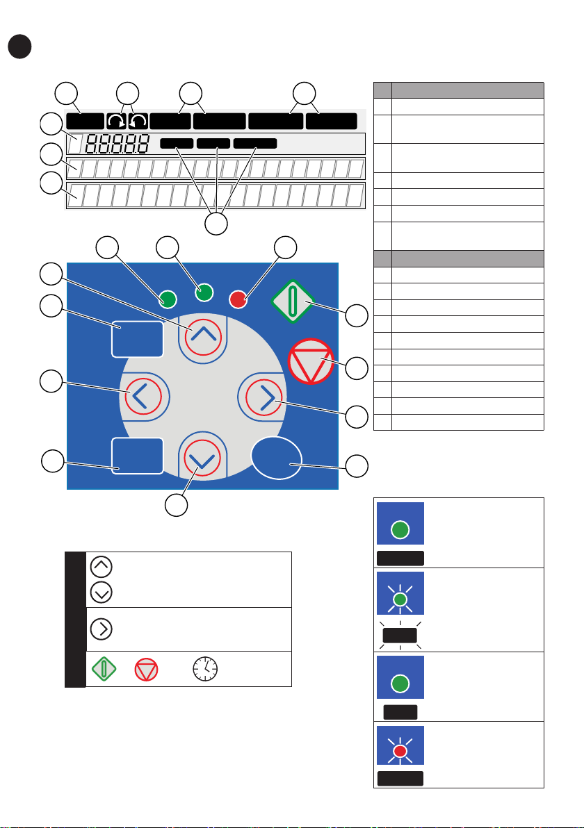
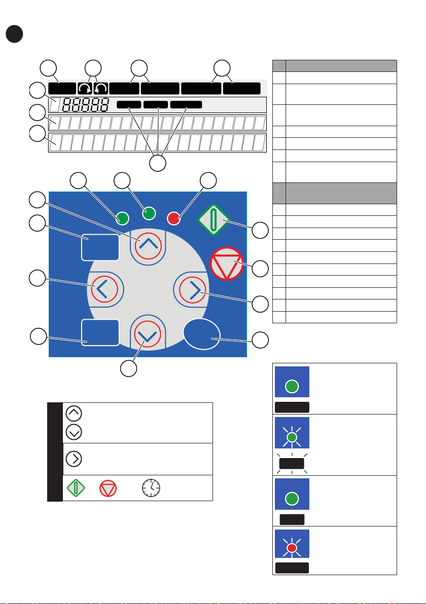
CONTROL PANEL AND KEYPAD
A.
1
RUN
4
2 1
READY
5
6
B.
17
8 8 8
ready
run
16
reset
15
7
Bus/CommKeypadI/O term
fault
ALARM
3
FAULTSTOP
A The text display
1 The indicators of status
The indicators of the rotation
2
direction
The indicators of alarm and
3
fault
4 The location indication
5 The description line
6 The value line
The indicators of the control
7
place
B The buttons of the keypad
8 The status LEDs
9 The Start button
10 The Stop button
9
11 The Menu button Right
12 The Enter button
13 The Browser button Down
10
14 The Select button
15 The Menu button Left
16 The Reset button
11
17 The Browser button Up
6
14
select enter
13
Selecting the keypad as the control place:
1. ‘M3 Control Keypad Menu’
2.
3.
or 3 sec
12
STATUS (1, 8)
The AC power is
connected to the
drive, no active
faults.
The AC drive
operates.
RUN
The STOP button
is pushed and the
drive ramps down.
The AC drive is
stopped because
of dangerous
conditions.
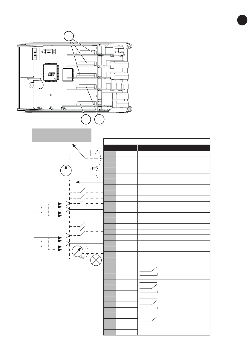
CONTROL TERMINALS
3
Reference potentiometer
1...10 k
1 Option Board A
The terminals for the standard
I/O connections
2 Option Board B
The terminals for 2 relay outputs
or 2 relay outputs and a thermistor
3 Option Board C, D, E
The option boards
21
Standard I/O
Terminal Signal
1 +10 Vref Reference voltage
2 AI1+ Analogue input, voltage or current
3 GND/AI1- Analogue input common
4 AI2+ Analogue input, voltage or current
5 GND/AI2- Analogue input common
6 24 Vout 24V aux. voltage
7 GND I/O ground
8 DI1 Digital input 1
9 DI2 Digital input 2
10 DI3 Digital input 3
11 CMA Common A for DIN1-DIN3
12 24 Vout Control voltage output
13 GND I/O ground
14 DI4 Digital input 4
15 DI5 Digital input 5
16 DI6 Digital input 6
17 CMB Common B for DIN4-DIN6
18 AO1+ Analogue signal (output)
19 AO-/GND Analogue output common
20 +24 Vin Open collector output
21 RO1/1 Relay output 1
22 RO1/2
23 RO1/3
24 RO2/1 Relay output 2
25 RO2/2
26 RO2/3
21 RO1/1 Relay output 1
22 RO1/2
23 RO1/3
24 RO2/1 Relay output 2
25 RO2/2
28 TI1+
29 TI1-
Thermistor input
EN
7

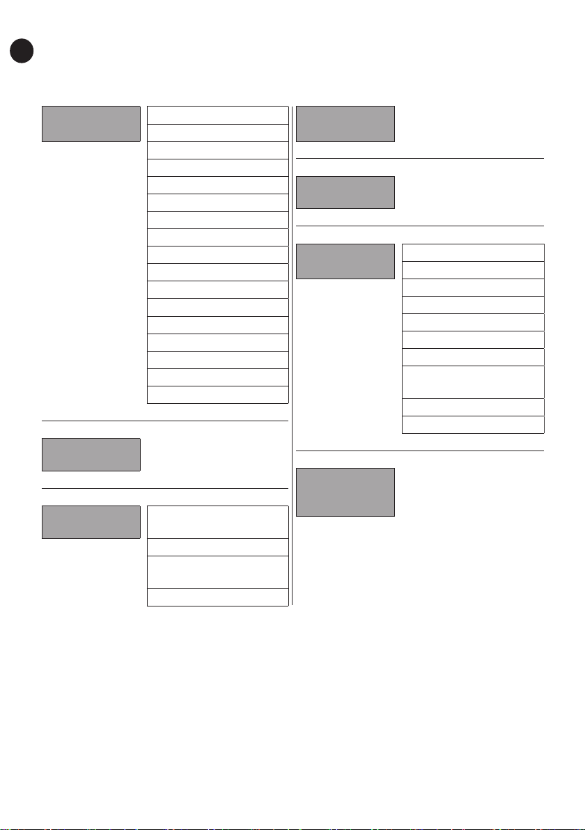
BASIC MENU STRUCTURE
EN
Main menu Submenus
M1
Monitor
M2
Parameters
M3
Keypad control
V1.1 Output frequency
V1.2 Frequency ref.
V1.3 Motor speed
V1.4 Motor current
V1.5 Motor torque
V1.6 Motor power
V1.7 Motor voltage
V1.8 DC-link voltage
V1.9 Unit temperature
V1.10 Motor temp.
V1.11 Analogue Input 1
V1.12 Analogue Input 2
V1.13 Current input
V1.14 DIN1, DIN2, DIN3
V1.15 DIN4, DIN5, DIN6
V1.16 Analogue output
V1.17 Multimonit. items
See Application Manual
P3.1 Control place
R3.2 Keypad reference
P3.3
Direction (on keypad)
P3.4 Stop button
Main menu Submenus
M4
Active faults
M5
Fault history
M6
System menu
M7
Expander
boards
S6.1 Language select.
S6.2
Application selection
S6.3 Copy parameters
S6.4 Compare param.
S6.5 Security
S6.6 Keypad settings
S6.7 Hardware settings
S6.8 System information
S6.9 Power monitor
S6.11
Power multi-monitor
8

FIRST START-UP
1. If the start-up wizard is active, select the language of the control panel and the
application. Accept the selections with the Enter button. If the start-up wizard is not
active, obey the instructions a and b.
a Select the language of the control panel from the Menu M6, page 6.1.
b Select the application from the Menu M6, page 6.2.
2. All parameters have factory default values. To make sure that the AC drive operates
correctly, make sure that these group G2.1 parameters have the same data as the
nameplate. For more information on the parameters in the list, see the VACON
One Application Manual.
• Nominal voltage of the motor
• Nominal frequency of the motor
• Nominal speed of the motor
• Nominal current of the motor
• Motor cos phi
®
All in
EN
9
FR
ready
READY
run
run
RUN
fault
FAULT
PANNEAU OPÉRATEUR
A.
1
RUN
4
2 1
5
6
B.
8 8 8
17
16
reset
15
14
Sélection du panneau opérateur comme
source de commande :
select enter
ready
13
READY
7
run
fault
ALARM
Bus/CommKeypadI/O term
3
FAULTSTOP
A L'affichage textuel
1 Indicateurs d'état
Indicateurs du sens de
2
rotation
Indicateurs d'alarme et de
3
défaut
4 Indication de position
5 Ligne de description
6 Ligne de valeur
Indicateurs de la source de
7
commande
Boutons du panneau
B
opérateur
8 Les voyants d’état
9 Touche marche
9
10 Touche arrêt
11 Touche de menu droite
12 Touche enter
10
13 Touche de navigation bas
14 La touche select (sélection)
15 Touche de menu gauche
11
16 La touche reset (réarmement)
17 Touche de navigation haut
12
STATUS (1, 8)
Le convertisseur de
fréquence est sous
tension et aucun
défaut n’est actif.
10
1.
2.
3.
‘Menu Contrôle du panneau
opérateur M3’
RUN
ou 3 sec
Le convertisseur
de fréquence
fonctionne.
La touche ARRÊT
est pressée et
le convertisseur
s’arrête.
Le convertisseur
de fréquence est
arrêté en raison
de conditions
dangereuses.
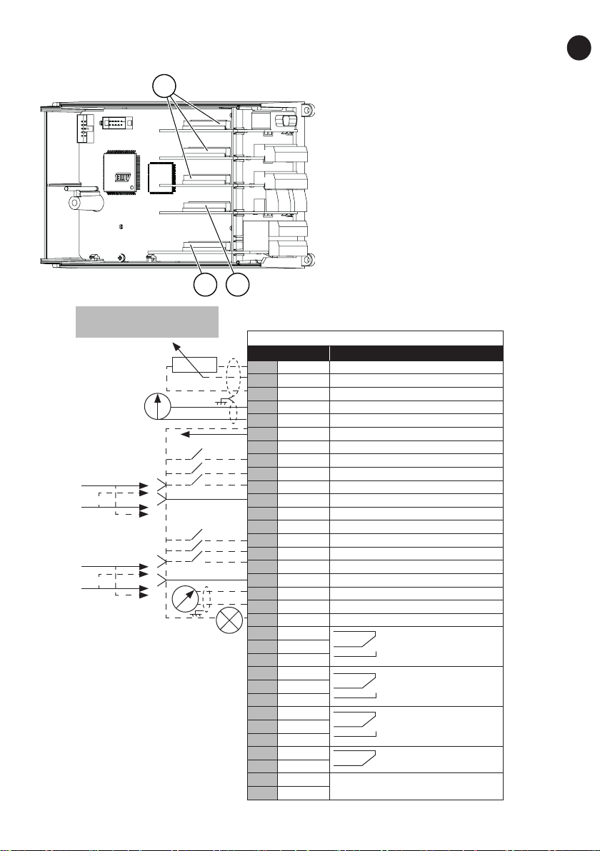
BORNES DE COMMANDE
3
FR
1 Option Board A
Bornes de connexion d’E/S standard
2 Option Board B
Bornes des 2 sorties relais ou 2
sorties relais et une thermistance
3 Option Board C, D, E
Cartes en option
21
Potentiomètre de référence,
1...10 k
E/S de base
Borne Signal
1 +10 Vref Tension référence
2 AI1+ Entrée analog. en tension ou courant
3 GND/AI1- Entrée analog. comm.
4 AI2+ Entrée analog. en tension ou courant
5 GND/AI2- Entrée analog. comm.
6 24 Vout 24 V tension aux.
7 GND Terre E/S
8 DI1 Entrée logique 1
9 DI2 Entrée logique 2
10 DI3 Entrée logique 3
11 CMA A commun pour DIN1-DIN3
12 24 Vout Sortie tension commde
13 GND Terre E/S
14 DI4 Entrée logique 4
15 DI5 Entrée logique 5
16 DI6 Entrée logique 6
17 CMB B commun pour DIN4-DIN6
18 AO1+ Signal analogique (sortie +)
19 AO-/GND Commun sortie analogique
20 +24 Vin Sortie à collecteur ouvert
21 RO1/1 Sortie relais 1
22 RO1/2
23 RO1/3
24 RO2/1 Sortie relais 2
25 RO2/2
26 RO2/3
21 RO1/1 Sortie relais 1
22 RO1/2
23 RO1/3
24 RO2/1 Sortie relais 2
25 RO2/2
28 TI1+
29 TI1-
Entrée thermistance
11
STRUCTURE DE MENU DE BASE
FR
Menu principal Sous-menus
M1
Affichage
M2
Paramètres
M3
Cde Panneau
V1.1 Fréquence moteur
V1.2 Ref.Fréq.
V1.3 Vitesse moteur
V1.4 Courant moteur
V1.5 Couple moteur
V1.6 Puissance moteur
V1.7 Tension moteur
V1.8 Tension bus c.c.
V1.9 Température
V1.10 Temp. moteur
V1.11 Entrée analogique 1
V1.12 Entrée analogique 2
V1.13 Entrée courant
V1.14 DIN1, DIN2, DIN3
V1.15 DIN4, DIN5, DIN6
V1.16 Sortie analogique
V1.17 Page Multi-Aff.
Voir manuel applicatif
P3.1
Source de commande
R3.2 Réf. panneau op.
P3.3
Direction (sur pan. op.)
R3.4 Touche Arrêt
Menu principal Sous-menus
M4
Défauts actifs
M5
Historiq défauts
M6
Menu Système
M7
Cartes
extension
S6.1 Langue
S6.2 Application
S6.3 Copie paramètres
S6.4 Compar. param.
S6.5 Sécurité
S6.6 Réglages Panneau
S6.7 Infos matériel
S6.8
Informations système
S6.9 Aff. Puissance
S6.11 MultiAff. Puiss.
12
 Loading...