

Operating Guide
VACON® NXP DCGuard™


Operating Guide | VACON® NXP DCGuard™
Contents
Contents
1 Introduction 5
1.1 Purpose of this Operating Guide 5
1.2 Additional Resources 5
1.3 Manual Version 5
1.4 Disposal 5
1.5 Type Approvals and Certifications 5
2 Safety 7
2.1 Safety Instructions 7
3 Product Overview 8
3.1 Intended Use 8
3.2 Application Functionality 8
3.3 Protection Functions 8
3.4 Controlled Voltage Ramp-Up 9
4 Electrical Installation 10
4.1 Cabling 10
4.1.1 Wiring Diagrams for Air-Cooled Inverter Units 10
4.1.2 Wiring Diagrams for Liquid-Cooled Inverter Units 13
4.2 Terminal Definitions 16
4.2.1 Terminal Locations in Air-Cooled Inverter Units 16
4.2.2 Terminal Locations in Liquid-Cooled Inverter Units 19
5 Control Unit 23
5.1 Control I/O Configuration 23
6 Parameter Settings 25
6.1 Setting the Parameters for the Application 25
6.2 Basic Parameters 25
6.3 Instant Current Cut-Off 26
6.4 Rapid Current Cut-Off 26
6.5 High Current Cut-Off 27
6.5.1 Parameter Settings for High Current Cut-Off 27
6.5.2 U Phase Current Protection 28
6.5.3 V Phase Current Protection 28
6.5.4 W Phase Current Protection 29
6.6 Over Load Protection 30
6.6.1 Function Description 30
6.6.2 U Phase Over Load Protection 31
AQ284746085202en-000201 / DPD02123 | 3Danfoss A/S © 2018.10

Operating Guide | VACON® NXP DCGuard™
6.6.3 V Phase Over Load Protection 31
6.6.4 W Phase Over Load Protection 32
6.7 Controlled Voltage Ramp-Up 33
Contents
AQ284746085202en-000201 / DPD021234 | Danfoss A/S © 2018.10

Operating Guide | VACON® NXP DCGuard™
Introduction
1 Introduction
1.1 Purpose of this Operating Guide
This operating guide provides information for the installation and operation of the VACON® NXP DCGuard™ application. It is intended
for use by qualified personnel. To use the drive safely and professionally, read and follow the instructions. Pay particular attention to
the safety instructions and general warnings. Always keep this operating guide available with the drive.
1.2 Additional Resources
Other resources are available to understand advanced AC drive functions, programming, and options.
• The VACON® NXP DCGuard™ design guide provides technical information to understand the capabilities of the VACON® NXP
DCGuard™ application.
• The VACON® NXP DCGuard™ application guide provides greater detail on how to work with the application software and how to
set the parameters of the AC drive modules.
• VACON® NXP Common DC Bus and VACON® NXP Liquid-cooled Common DC Bus user manuals provide detailed information for the
installation, commissioning, and operation of the AC drive modules.
• The operating and installation guides for VACON® options give detailed information about specific drive options.
Supplementary publications and manuals are available from Danfoss. See www.danfoss.com for listings.
1.3 Manual Version
This manual is regularly reviewed and updated. All suggestions for improvement are welcome.
The original language of this manual is English.
Table 1: VACON® NXP DCGuard™ Operating Guide Version
Version Release date Remarks
B 25.10.2018 Product name update
1.4 Disposal
Context:
Do not dispose of equipment containing electrical components together with domestic waste. Collect it separately in accordance with
local and currently valid legislation.
1.5 Type Approvals and Certifications
VACON® NXP DCGuard™ is type approved as a circuit breaker/DC-bus tie breaker. For a list of the approvals and certifications, see the
VACON® NXP DCGuard™ product page at www.danfoss.com.
Danfoss A/S © 2018.10
AQ284746085202en-000201 / DPD02123 | 5

Operating Guide | VACON® NXP DCGuard™
NOTI CE
VACON® NXP DCGuard™ acts as a protection device in a DC power distribution system. Separate approvals as a DC-bus tie
breaker can be required.
Introduction
6 | Danfoss A/S © 2018.10
AQ284746085202en-000201 / DPD02123

Operating Guide | VACON® NXP DCGuard™
Safety
2 Safety
2.1 Safety Instructions
A safety guide is included in the product delivery. Read the safety instructions carefully before starting to work in any way with the
system or its components.
The warnings and cautions in the safety guide give important information on how to prevent injury and damage to the equipment or
the system. Read the warnings and cautions carefully and obey their instructions.
The product manuals with applicable safety, warning, and caution information can be downloaded from https://www.danfoss.com/en/
service-and-support/.
Danfoss A/S © 2018.10
AQ284746085202en-000201 / DPD02123 | 7
W
V
DC+
DCGuard 1 DCGuard 2
DC-
DC+
DC-
DC+
DC-
U
V
DC bus 1
AFE
INU
=
~
=
=
=
=
=
~
=
~
M
M
G
INU
DC bus 2
e30bg860.11
AFE
INU
=
~
=
~
=
~
M
M
G
INU
Operating Guide | VACON® NXP DCGuard™
Product Overview
3 Product Overview
3.1 Intended Use
Utilizing DC grids rather than AC grids enables power distribution with lower power losses. However, there are few or no international
standards for building a DC grid, especially in marine applications. Short circuit handling is a challenge in DC grids and it is difficult to
ensure the required system functionality by using fuses. Ensuring selectivity and limited short circuit energy requires more
sophisticated protection devices.
Danfoss has therefore developed the VACON® NXP DCGuard™, a semiconductor protection device that can detect and cut off any DC
fault currents and isolate the faulty part of the DC grid power distribution system in microseconds.
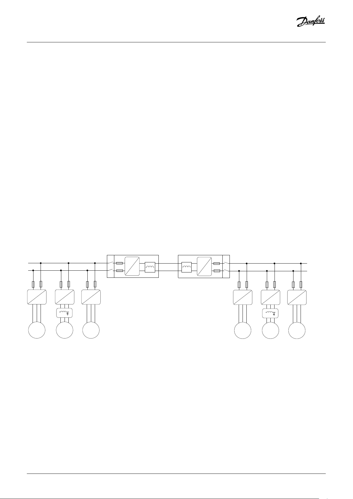
3.2 Application Functionality
VACON® NXP DCGuard™ is a fast DC current cutter device that detects and cuts off an outgoing short-circuit current. The main
function is to isolate the faulty DC bus from the healthy DC bus, before that fault affects the healthy DC bus.
Two inverter units in a DCGuard peer-to-peer topology are required to be able to cut off short-circuit current both ways.
VACON® NXP DCGuard™ consist of VACON® NXP inverter units and application software ADFIF102. To ensure the correct functionality
and safety level, always use the following components together with the DCGuard in a peer-to-peer system:
• An upstream mechanical disconnector if safe disconnection is required.
• Type aR supply fuses in each DC supply line (see the VACON® NXP DCGuard™ design guide for instructions).
• A dU/dt filter (a standard VACON® dU/dt filter can be used).
Illustration 1: VACON® NXP DCGuard™ Peer-to-Peer Topology
3.3 Protection Functions
The VACON® NXP DCGuard™ application has different short-circuit protection levels. The instant current cut-off is non-programmable,
but the other functions can be programmed. The protection functions also have separate programmable responses.
Instant current cut-off
•
Non-programmable
• Handled by VACON® NXP hardware at μs level.
• Fault: F1
8 | Danfoss A/S © 2018.10
AQ284746085202en-000201 / DPD02123
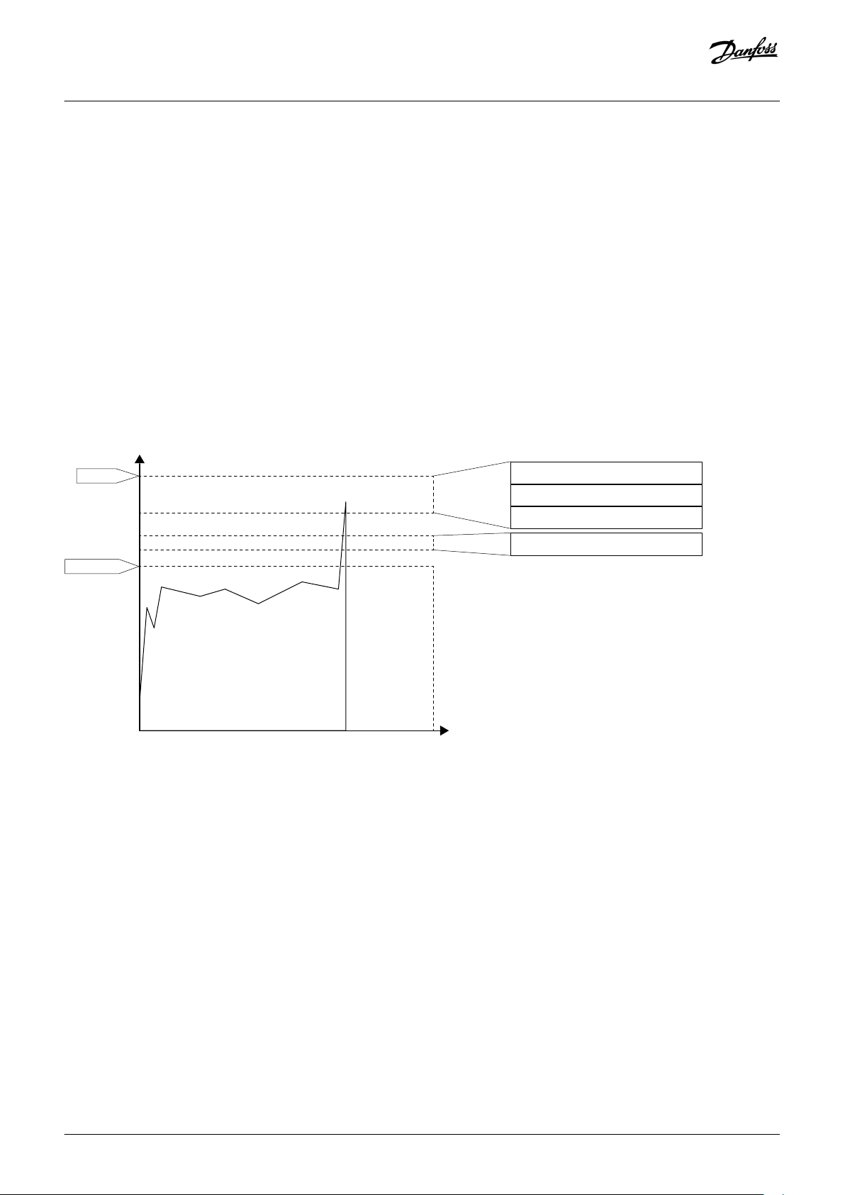
Over load detection
Short-circuit protection
Operational area
Current
Time
Nom. current
Instant trip
Instant current cut-off
Rapid current cut-off
High current cut-off
Bus tie cables over load protection
e30bg894.10
Operating Guide | VACON® NXP DCGuard™
Rapid current cut-off
• Programmable
• Requires sufficient inductance in the output filter
• Handled by the system software at 50–100 μs level
• Faults: F63, F64, and F65
High current cut-off
• Programmable
• Handled by the application software at 100 ms level
• Faults: F86, F87, and F88
Over load detection
• Programmable
• Handled by the application software at 100 ms level
• Faults: F83, F84, and F85
Product Overview
Illustration 2: VACON® NXP DCGuard™ Safety Layers
3.4 Controlled Voltage Ramp-Up
Controlled voltage ramp-up is a programmable function of the VACON® NXP DCGuard™ application. The DCGuard performs a
controlled ramp-up of the voltage in the bus tie cables before closing. This functionality powers up the DC link of the peer-to-peer
connection during start-up of the system. The recommended controlled voltage ramp-up time is 200–400 ms.
Danfoss A/S © 2018.10
AQ284746085202en-000201 / DPD02123 | 9
Operating Guide | VACON® NXP DCGuard™
Electrical Installation
4 Electrical Installation
4.1 Cabling
The cabling of the VACON® NXP DCGuard™ inverter units is different depending on the unit type and nominal current of the units. See:
• 4.1.1 Wiring Diagrams for Air-Cooled Inverter Units
• 4.1.2 Wiring Diagrams for Liquid-Cooled Inverter Units
Definitions for the wiring diagrams:
Item Definition
-F Fuse, type aR. See the VACON® NXP DCGuard™ design guide for instructions on fuse selection.
-K Mechanical disconnector
-L Output di/dt filter
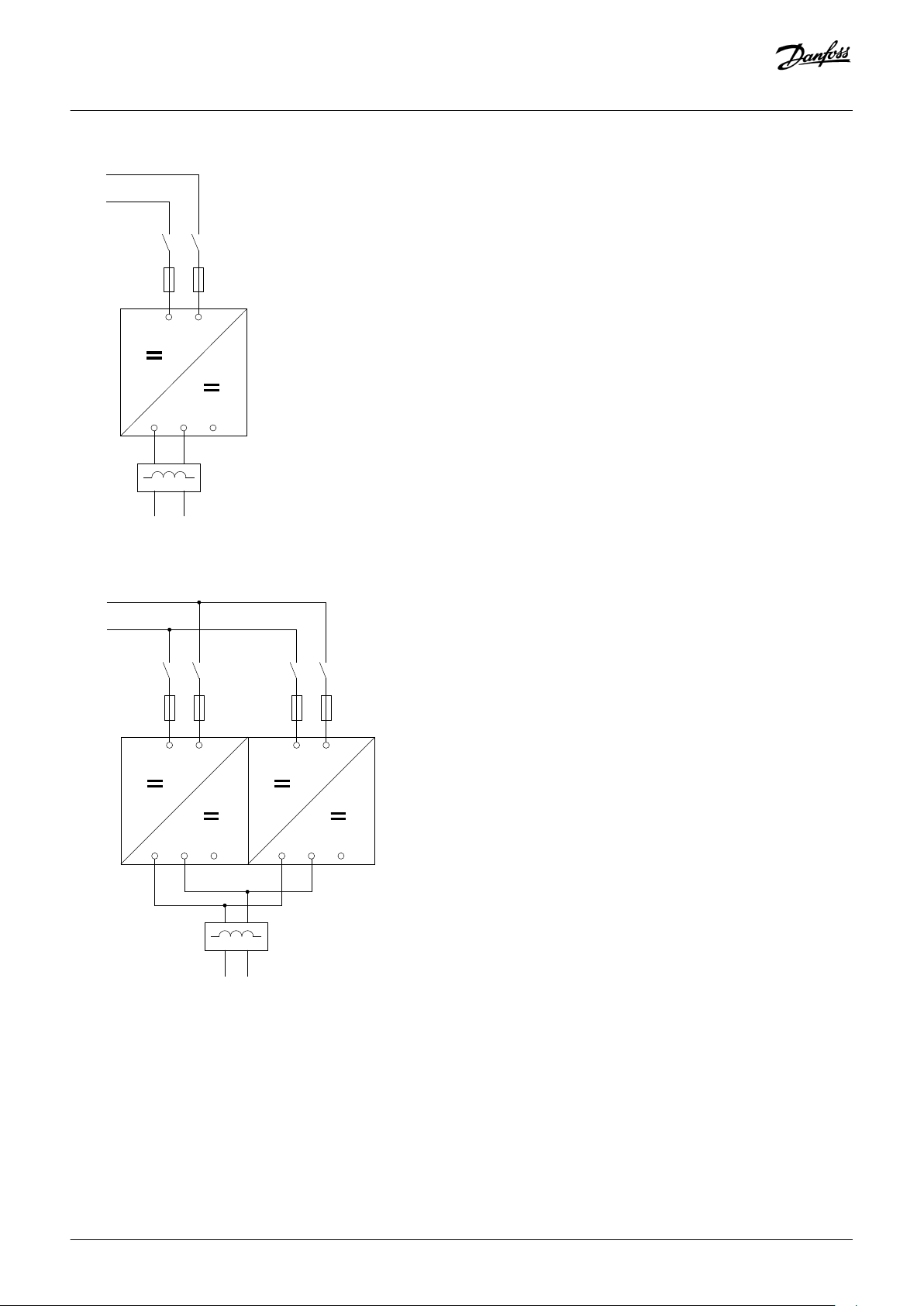
4.1.1 Wiring Diagrams for Air-Cooled Inverter Units
Wiring diagrams for air-cooled inverter units, 500 V (465–800 V DC):
• NXP0003–NXP0520, enclosure sizes FR4 to FI10, see illustration 3.
• NXP0590–NXP0730, enclosure size FI12, see illustration 4.
• NXP0820–NXP1030, enclosure size FI12, see
• NXP1150–NXP1450, enclosure size FI13, see illustration 6.
• NXP1770–NXP2150, enclosure size FI14, see
Wiring diagrams for air-cooled inverter units, 690 V (640–1100 V DC):
• NXP0004–NXP0416, enclosure sizes FR4 to FI10, see illustration 3.
• NXP0460–NXP0590, enclosure size FI12, see
• NXP0650–NXP0820, enclosure size FI12, see illustration 5.
• NXP0920–NXP1180, enclosure size FI13, see
• NXP1500–NXP2250, enclosure size FI14, see illustration 7.
illustration 5.
illustration 7.
illustration 4.
illustration 6.
10 | Danfoss A/S © 2018.10
AQ284746085202en-000201 / DPD02123
U
V
B+
-F1.1
-K1.1
-K1.2
e30bg884.10
-F1.2
-L1
DC+
DC-
DC+ DC-
B-
W
-L1
DC+
DC-
U
V
B+
B-
W U
V
B+
B-
W
-F1.1
-K1.1
-K1.2
-F1.2
-F2.1
-K2.1
-K2.2
-F2.2
DC+
DC-
e30bg885.10
Operating Guide | VACON® NXP DCGuard™
Electrical Installation
Illustration 3: Basic Wiring Diagram for Enclosure Sizes FR4–FI10
Illustration 4: Basic Wiring Diagram for Enclosure Size FI12 with 1 Output Filter (only valid for 500 V NXP0590–NXP0730 and 690 V NXP0460–
NXP0590)
Danfoss A/S © 2018.10
AQ284746085202en-000201 / DPD02123 | 11

-L1
-L2
U
V
B+
B-
W U
V
B+
B-
W
DC+ DC-
DC+ DC-
-F1.1
-K1.1
-K1.2
-F1.2
-F2.1
-K2.1
-K2.2
-F2.2
DC+
DC-
e30bg886.10
-L1
U
B+
DC+
DC-
B-
V
B+
B-
W
B+
B-
-F1.1
-K1.1
-K1.2
-F1.2
-F2.1
-K2.1
-K2.2
-F2.2
-F3.1
-K3.1
-K3.2
-F3.2
DC+
DC-
e30bg887.10
Operating Guide | VACON® NXP DCGuard™
Electrical Installation
Illustration 5: Basic Wiring Diagram for Enclosure Size FI12 with 2 Output Filters
Illustration 6: Basic Wiring Diagram for Enclosure Size FI13
12 | Danfoss A/S © 2018.10
AQ284746085202en-000201 / DPD02123

-L1
-L2
DC+ DC- DC+ DC-
U
B+ B-
V
B+
B-
W
B+ B-
U
B+ B-
V
B+ B-
W
B+ B-
-F1.1
-K1.1
-K1.2
-F1.2 -F2.1
-K2.1 -K2.2
-F2.2
-F3.1
-K3.1
-K3.2
-F3.2
-F4.1
-K4.1
-K4.2
-F4.2 -F5.1
-K5.1
-K5.2
-F5.2 -F6.1
-K6.1
-K6.2
-F6.2
DC+
DC-
e30bg888.10
Operating Guide | VACON® NXP DCGuard™
Electrical Installation
Illustration 7: Basic Wiring Diagram for Enclosure Size FI14
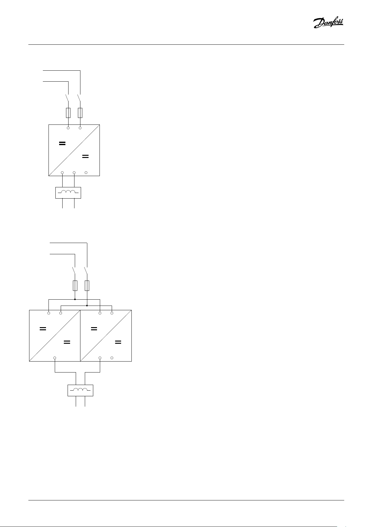
4.1.2 Wiring Diagrams for Liquid-Cooled Inverter Units
Wiring diagrams for liquid-cooled inverter units, 500 V (465–800 V DC):
• NXP0016–NXP0730, enclosure sizes CH3 to CH62, see illustration 8.
• NXP0820–NXP1150, enclosure size CH63, see illustration 9.
• NXP1370, enclosure size CH64, see
• NXP1640–NXP2300, enclosure size CH64, see illustration 11.
• NXP2470–NXP4140, enclosure size 2 x CH64, see
Wiring diagrams for liquid-cooled inverter units, 690 V (640–1100 V DC):
• NXP0170–NXP0502, enclosure sizes CH61 to CH62, see illustration 8.
• NXP0590–NXP0750, enclosure size CH63, see
• NXP0820–NXP1500, enclosure size CH64, see illustration 10.
• NXP1700, enclosure size CH64, see
• NXP1850–NXP3100, enclosure size 2 x CH64, see illustration 12.
illustration 10.
illustration 11.
illustration 12.
illustration 9.
Danfoss A/S © 2018.10
AQ284746085202en-000201 / DPD02123 | 13
U
V
B+
-F1.1
-K1.1
-K1.2
e30bg884.10
-F1.2
-L1
DC+
DC-
DC+ DC-
B-
W
-L1
DC+ DC-
U
B+
B-
V
B+
B-
W
-F1.1
-K1.1
-K1.2
-F1.2
DC+
DC-
e30bg889.10
Operating Guide | VACON® NXP DCGuard™
Electrical Installation
Illustration 8: Basic Wiring Diagram for Enclosure Sizes CH3–CH62
Illustration 9: Basic Wiring Diagram for Enclosure Size CH63
14 | Danfoss A/S © 2018.10
AQ284746085202en-000201 / DPD02123

-L1
U
B+
DC+
DC-
B-
V
B+
B-
W
B+
B-
-F1.1
-K1.1
-K1.2
-F1.2
-F1.3
-K1.3
-K1.4
-F1.4
DC+
DC-
e30bg890.10
-L1
U
B+
B-
V
B+
B-
W
B+
B-
-F1.1
-K1.1
-F1.2
-K1.2
-F1.3
-K1.3
-F1.4
-K1.4
-F1.5
-K1.5
-F1.6
-K1.6
-F1.7
-K1.7
-F1.8
-K1.8
DC+
DC-
DC+
DC-
e30bg891.10
Operating Guide | VACON® NXP DCGuard™
Electrical Installation
Illustration 10: Basic Wiring Diagram for Enclosure Size CH64 with 4 Input Fuses
Illustration 11: Basic Wiring Diagram for Enclosure Size CH64 with 8 Input Fuses
Danfoss A/S © 2018.10
AQ284746085202en-000201 / DPD02123 | 15

-F1.1
-K1.1
-K1.2
-F1.2
-F1.3
-K1.3
-K1.4
-F1.4
-F1.5
-K1.5
-K1.6
-F1.6
-F1.7
-K1.7
-K1.8
-F1.8
U
B+
B-
V
B+
B-
W
B+
B-
U
B+ B-
V
B+ B-
W
B+ B-
-L1
-L2
DC+
DC-
DC+ DC-
DC+
DC-
e30bg892.10
U V WB-
e30bg871.10
B+
Operating Guide | VACON® NXP DCGuard™
Electrical Installation
Illustration 12: Basic Wiring Diagram for Enclosure Size 2 x CH64
4.2 Terminal Definitions
The terminals used in the VACON® NXP DCGuard™ application are:
• DC-bus connections: Terminals B+ and B-
• Peer-to-peer connections: Terminals U, V, and W
The locations of the terminals in the different inverter unit enclosure sizes are shown in the illustrations in:
4.2.1 Terminal Locations in Air-Cooled Inverter Units
•
•
4.2.2 Terminal Locations in Liquid-Cooled Inverter Units
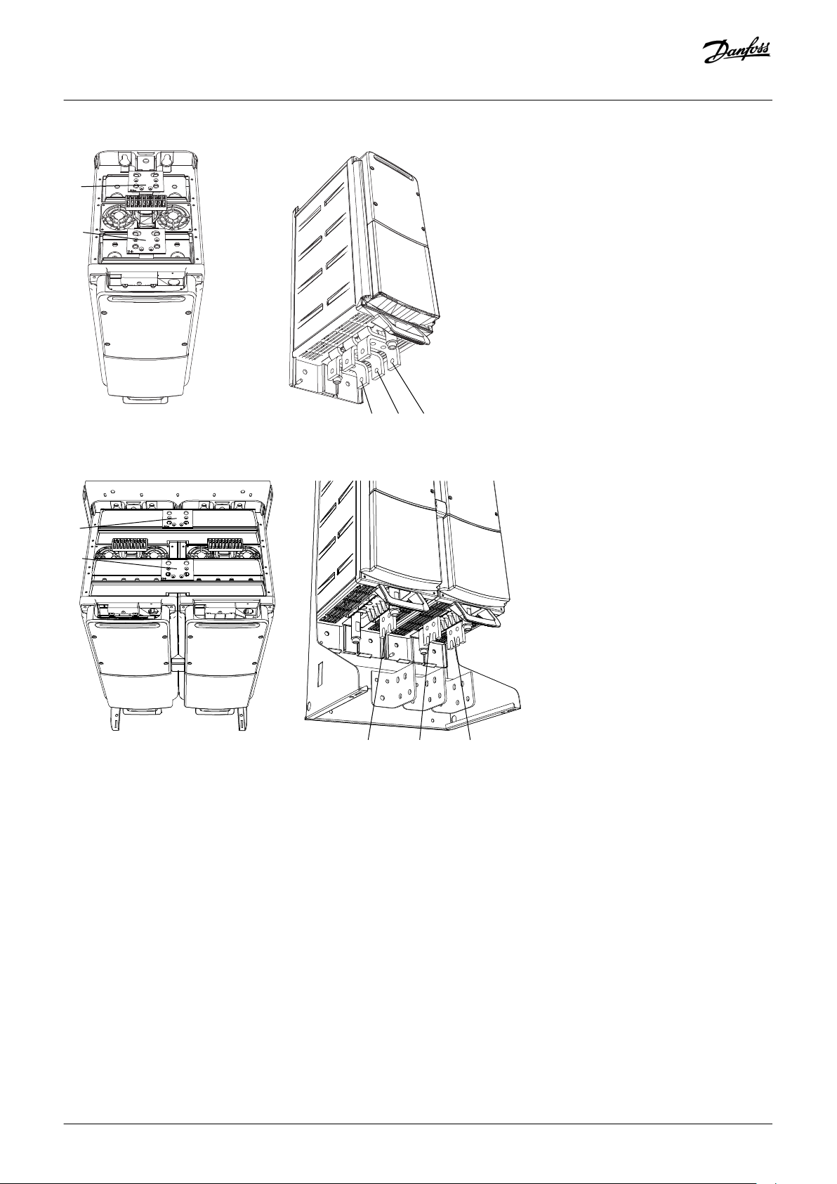
4.2.1 Terminal Locations in Air-Cooled Inverter Units
Illustration 13: Terminal Locations in Enclosure Sizes FR4 and FR5
16 | Danfoss A/S © 2018.10
AQ284746085202en-000201 / DPD02123

U
V WB- B+
e30bg872.10
U
V WB- B+
e30bg873.10
U V
W
B+
B-
e30bg874.10
Operating Guide | VACON® NXP DCGuard™
Illustration 14: Terminal Locations in Enclosure Size FR6
Electrical Installation
Illustration 15: Terminal Locations in Enclosure Size FR7
Illustration 16: Terminal Locations in Enclosure Size FR8
Danfoss A/S © 2018.10
AQ284746085202en-000201 / DPD02123 | 17

B+ B-
U
V
W
e30bg875.10
U V W
B+ B-
B+
B-
B+
B-
e30bg876.10
Operating Guide | VACON® NXP DCGuard™
Illustration 17: Terminal Locations in Enclosure Sizes FI9, FI10, and FI12
Electrical Installation
Illustration 18: Terminal Locations in Enclosure Sizes FI13 and FI14
18 | Danfoss A/S © 2018.10
AQ284746085202en-000201 / DPD02123

B- B+UV
W
e30bg877.10
B+
B-
W
V
U
e30bg878.10
Operating Guide | VACON® NXP DCGuard™
4.2.2 Terminal Locations in Liquid-Cooled Inverter Units
Illustration 19: Terminal Locations in Enclosure Size CH3
Electrical Installation
Illustration 20: Terminal Locations in Enclosure Size CH4
Danfoss A/S © 2018.10
AQ284746085202en-000201 / DPD02123 | 19

B+
B-
U
V
W
e30bg879.10
B+
W V U
B-
e30bg880.10
Operating Guide | VACON® NXP DCGuard™
Illustration 21: Terminal Locations in Enclosure Size CH5
Electrical Installation
Illustration 22: Terminal Locations in Enclosure Size CH61
20 | Danfoss A/S © 2018.10
AQ284746085202en-000201 / DPD02123
B+
B-
W V U
e30bg881.10
B+
U V W
B-
e30bg882.10
Operating Guide | VACON® NXP DCGuard™
Illustration 23: Terminal Locations in Enclosure Size CH62
Electrical Installation
Illustration 24: Terminal Locations in Enclosure Size CH63
Danfoss A/S © 2018.10
AQ284746085202en-000201 / DPD02123 | 21

B+
B-
U V W
e30bg883.10
Operating Guide | VACON® NXP DCGuard™
Illustration 25: Terminal Locations in Enclosure Size CH64
Electrical Installation
22 | Danfoss A/S © 2018.10
AQ284746085202en-000201 / DPD02123

Operating Guide | VACON® NXP DCGuard™
Control Unit
5 Control Unit
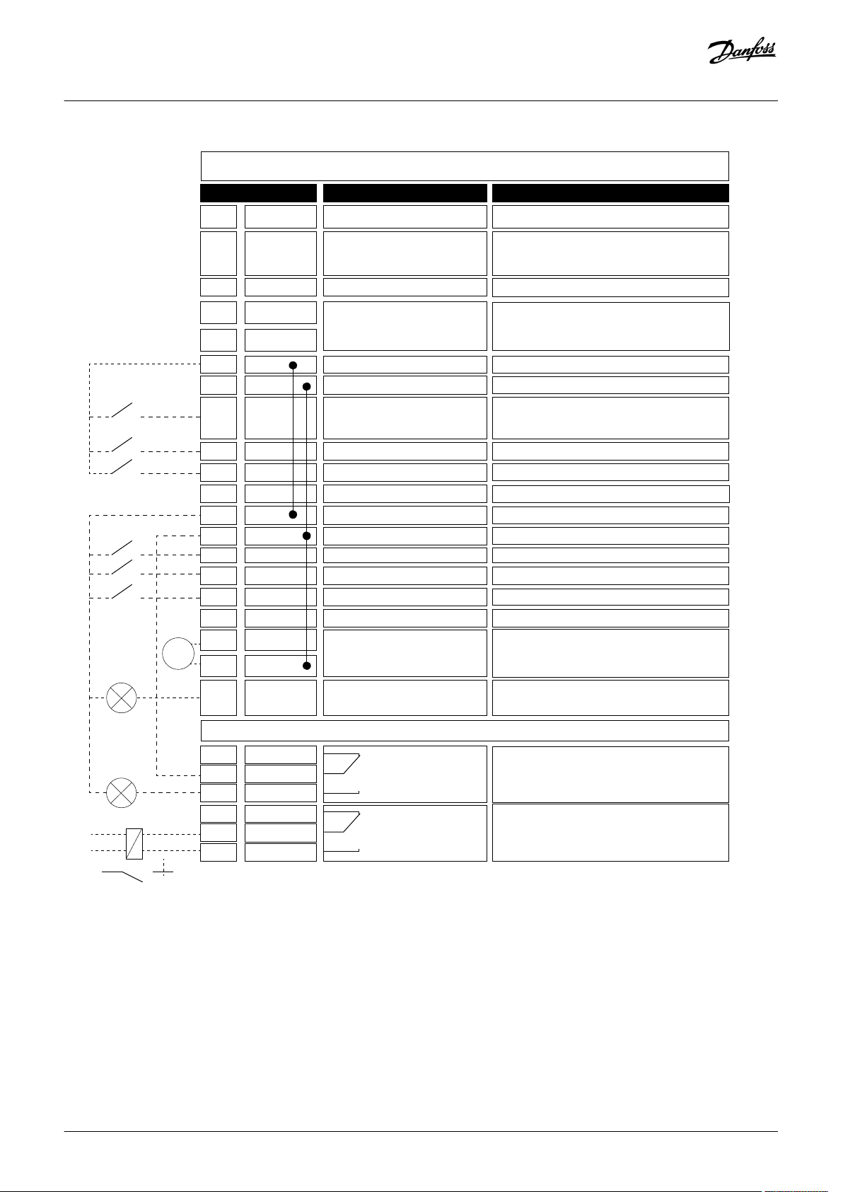
5.1 Control I/O Configuration
The figure shows the default I/O configuration for the VACON® NXP DCGuard™ application and a basic description of the terminals and
signals of the I/O board.
For more information on control terminals, see the VACON® NXP DCGuard™ application guide.
Danfoss A/S © 2018.10
AQ284746085202en-000201 / DPD02123 | 23
1
6
2
3
4
5
18
READY
RUN
mA
19
20
12
7
13
8
9
10
14
15
16
21
OPTA2
22
23
11
17
24
25
26
Standard I/O board
Terminal Signal
Description
+10Vref Reference voltage output
e30bg859.10
Voltage for potentiometer, etc.
AI1+
Analog input 1
Range 0-10 V, Ri = 200 Ω
Range 0-20 mA Ri = 250 Ω
Range 0-10 V, Ri = 200 Ω
Range 0-20 mA Ri = 250 Ω
Analog input 1
Input range selected by jumpers
Default range: Voltage 0-10 V
AI1-
I/O Ground Ground for reference and controls
AI2+
Analog input 2
Analog input 2
Input range selected by jumpers
Default range: Current 0-20 mA
AI2-
+24V
Control voltage output
Voltage for switches, etc. max 0.1 A
GND
I/O ground
Ground for reference and controls
DIN1
Start Request
(Close Request)
Programmable G2.2
Contact closed = Start Request
(Contact closed = Close Request)
DIN2
Programmable G2.2
No function defined at default
DIN3
Programmable G2.2
No function defined at default
CMA
Common for DIN1-DIN3
Connect to GND or +24 V
+24V
Control voltage output
Voltage for switches (see #6)
GND
I/O ground
Ground for reference and controls
DIN4
Programmable G2.2
No function defined at default
DIN5
Programmable G2.2
No function defined at default
DIN6
Programmable G2.2
No function defined at default
CMB
Common for DIN4-DIN6
Connect to GND or +24 V
AO1+
Analog output 1
Programmable G2.3
Output range selected by jumpers
Range 0-20 mA, RL max. 500 Ω
Range 0-10 V, RL > 1 kΩ
AO1-
DO1
Digital output
Programmable G2.3
Programmable
Open collector, I ≤ 50 mA, U ≤ 48 V DC
RO1
Relay output 1
Programmable G2.3
Programmable G2.3
Switching capacity
24 V DC / 8 A
250 V AC / 8 A
125 V DC / 0.4 A
RO1
RO1
RO2
Relay output 2
Switching capacity
24 V DC / 8 A
250 V AC / 8 A
125 V DC / 0.4 A
RO2
RO2
220
VAC
Operating Guide | VACON® NXP DCGuard™
Control Unit
Illustration 26: The Default I/O Configuration for the VACON® NXP DCGuard™ Application
24 | Danfoss A/S © 2018.10
AQ284746085202en-000201 / DPD02123

L
L
W
V
L
DC+
+
+
-
L
DC-
DC+
DC-
U
V
=
=
=
=
L
U
L
W
e30bg863.10
L
L
U
V
L
DC+
L
DC-
DC+
DC-
U
V
=
=
=
=
W
W
e30bg864.10
+
-
L
U
V
DC+
L
DC-
DC+
DC-
U
V
=
=
=
=
L
W
L
W
e30bg865.10
+
-
Operating Guide | VACON® NXP DCGuard™
Parameter Settings
6 Parameter Settings
6.1 Setting the Parameters for the Application
This chapter lists and describes the parameters which must be set up for the VACON® NXP DCGuard™ application.
For more details and a list of all available parameters, see the VACON® NXP DCGuard™ application guide.
6.2 Basic Parameters
6.2.1 (ID 1503) Cabling
Location in the menu: P2.1.1
Use this parameter to select the cabling type of the DCGuard unit. Select the parameter according to the cabling set-up used in the
peer-to-peer installation. The available options are:
• 0 = Not selected
The default setting. Drive operation is disabled.
• 1 = Three cable connection, U = DC+, V = DC-, W = DC+
Illustration 27: DCGuard Three Cable Connection
• 2 = Two cable connection, U = DC+, V = DC-, W = not connected
Illustration 28: DCGuard Two Cable Connection with Phases U and V
• 3 = Two cable connection, V = DC-, W = DC+, U = not connected
Illustration 29: DCGuard Two Cable Connection with Phases V and W
In a two cable peer-to-peer system, it is recommended to use the following set-up for the DCGuard units:
• DCGuard 1: U = DC+, V = DC-, W = not connected
- Cabling type 2
• DCGuard 2: V = DC-, W = DC+, U = not connected
- Cabling type 3
Danfoss A/S © 2018.10
AQ284746085202en-000201 / DPD02123 | 25

L
L
W
V
L
DC+
DCGuard 1
DCGuard 2
L
DC-
DC+
DC-
U
V
=
=
=
=
U
W
e30bg866.10
+
-
Operating Guide | VACON® NXP DCGuard™
Illustration 30: The Recommended DCGuard Two Cable Connection
Parameter Settings
6.3 Instant Current Cut-Off
The VACON® NXP inverter handles the instant current cut-off and the function cannot be programmed. The tripping limit for the
inverter is 3–4 x IH.
6.4 Rapid Current Cut-Off
Set the tripping limit of the rapid current cut-off for each phase with parameters:
• U Phase Trip Limit (P2.4.1.1)
• V Phase Trip Limit (P2.4.1.2)
• W Phase Trip Limit (P2.4.1.3)
Set the response to the SW trips with parameter:
• SW Trip Response (P2.4.1.6)
6.4.1 (ID 1500) U Phase Trip Limit
Location in the menu: P2.4.1.1
Use this parameter to set the trip limit for the rapid current cut-off in the U phase. The tripping limit is set in % of the nominal current.
The default setting in the peer-to-peer topology is 150%. The trip triggers fault F63.
• Nominal current in air-cooled inverter units = I
• Nominal current in liquid-cooled inverter units = I
The system software handles the current cut-off functionality. The functionality depends on a sufficient inductance in the output filter.
Standard dU/dt filters do not have enough inductance to ensure an exact tripping level.
L
TH
6.4.2 (ID 1501) V Phase Trip Limit
Location in the menu: P2.4.1.2
Use this parameter to set the trip limit for the rapid current cut-off in the V phase. The tripping limit is set in % of the nominal current.
The default setting in the peer-to-peer topology is 150%. The trip triggers fault F64.
• Nominal current in air-cooled inverter units = I
• Nominal current in liquid-cooled inverter units = I
26 | Danfoss A/S © 2018.10
L
TH
AQ284746085202en-000201 / DPD02123

Operating Guide | VACON® NXP DCGuard™
The system software handles the current cut-off functionality. The functionality depends on a sufficient inductance in the output filter.
Standard dU/dt filters do not have enough inductance to ensure an exact tripping level.
Parameter Settings
6.4.3 (ID 1502) W Phase Trip Limit
Location in the menu: P2.4.1.3
Use this parameter to set the trip limit for the rapid current cut-off in the W phase. The tripping limit is set in % of the nominal current.
The default setting in the peer-to-peer topology is 150%. The trip triggers fault F65.
• Nominal current in air-cooled inverter units = I
• Nominal current in liquid-cooled inverter units = I
The system software handles the current cut-off functionality. The functionality depends on a sufficient inductance in the output filter.
Standard dU/dt filters do not have enough inductance to ensure an exact tripping level.
L
TH
6.4.4 (ID 1874) SW Trip Response
Location in the menu: P2.4.1.6
Use this parameter to set the SW trip response when the current is above the limit set for the rapid current cut-off (see ID 1500, ID 1501,
and ID 1502).
• 0 = No Action
• 1 = Warning information
• 2 = Fault
For selection 2, there is a separate fault code for each phase:
• F63, U phase overcurrent
• F64, V phase overcurrent
• F65, W phase overcurrent
6.5 High Current Cut-Off
6.5.1 Parameter Settings for High Current Cut-Off
Set the response to the high current cut-off for each phase with parameters:
• U High Current Response (P2.8.5.1)
• V High Current Response (P2.8.6.1)
• W High Current Response (P2.8.7.1)
Set the tripping limit of the high current cut-off for each phase with parameters:
• U Trip Limit (P2.8.5.2)
• V Trip Limit (P2.8.6.2)
• W Trip Limit (P2.8.7.2)
Set the trip delay for the high current cut-off for each phase with parameters:
Danfoss A/S © 2018.10
AQ284746085202en-000201 / DPD02123 | 27

Operating Guide | VACON® NXP DCGuard™
• U Trip Delay (P2.8.5.3)
• V Trip Delay (P2.8.6.3)
• W Trip Delay (P2.8.7.3)
Parameter Settings
6.5.2 U Phase Current Protection
6.5.2.1 (ID 1550) U High Current Response
Location in the menu: P2.8.5.1
Use this parameter to set the trip response when the current is above the set limit in phase U for the time set for the high current cutoff.
• 0 = No Action
• 1 = Warning information
• 2 = Fault
Selection 2 gives the fault code F86, U high current.
6.5.2.2 (ID 1551) U Trip Limit
Location in the menu: P2.8.5.2
Use this parameter to set the trip limit for the high current cut-off in the U phase. The tripping limit is set in % of the nominal current.
The trip triggers fault F86.
• Nominal current in air-cooled inverter units = I
• Nominal current in liquid-cooled inverter units = I
The application software handles the current cut-off functionality at the 10 ms level.
L
TH
6.5.2.3 (ID 1552) U Trip Delay
Location in the menu: P2.8.5.3
Use this parameter to set the trip delay for the high current cut-off in the U phase.
6.5.3 V Phase Current Protection
6.5.3.1 (ID 1553) V High Current Response
Location in the menu: P2.8.6.1
Use this parameter to set the trip response when the current is above the set limit in phase V for the time set for the high current cutoff.
• 0 = No Action
• 1 = Warning information
• 2 = Fault
28 | Danfoss A/S © 2018.10
AQ284746085202en-000201 / DPD02123

Operating Guide | VACON® NXP DCGuard™
Selection 2 gives the fault code F87, V high current.
Parameter Settings
6.5.3.2 (ID 1554) V Trip Limit
Location in the menu: P2.8.6.2
Use this parameter to set the trip limit for the high current cut-off in the V phase. The tripping limit is set in % of the nominal current.
The trip triggers fault F87.
• Nominal current in air-cooled inverter units = I
• Nominal current in liquid-cooled inverter units = I
The application software handles the current cut-off functionality at the 10 ms level.
L
TH
6.5.3.3 (ID 1555) V Trip Delay
Location in the menu: P2.8.6.3
Use this parameter to set the trip delay for the high current cut-off in the V phase.
6.5.4 W Phase Current Protection
6.5.4.1 (ID 1556) W High Current Response
Location in the menu: P2.8.7.1
Use this parameter to set the trip response when the current is above the set limit in phase W for the time set for the high current cutoff.
• 0 = No Action
• 1 = Warning information
• 2 = Fault
Selection 2 gives the fault code F88, W high current.
6.5.4.2 (ID 1558) W Trip Limit
Location in the menu: P2.8.7.2
Use this parameter to set the trip limit for the high current cut-off in the W phase. The tripping limit is set in % of the nominal current.
The trip triggers fault F88.
• Nominal current in air-cooled inverter units = I
• Nominal current in liquid-cooled inverter units = I
The application software handles the current cut-off functionality at the 10 ms level.
Danfoss A/S © 2018.10
L
TH
AQ284746085202en-000201 / DPD02123 | 29

t
10 ms
B
A
In
C
D
E
F
e30bg867.10
Operating Guide | VACON® NXP DCGuard™
Parameter Settings
6.5.4.3 (ID 1559) W Trip Delay
Location in the menu: P2.8.7.3
Use this parameter to set the trip delay for the high current cut-off in the W phase.
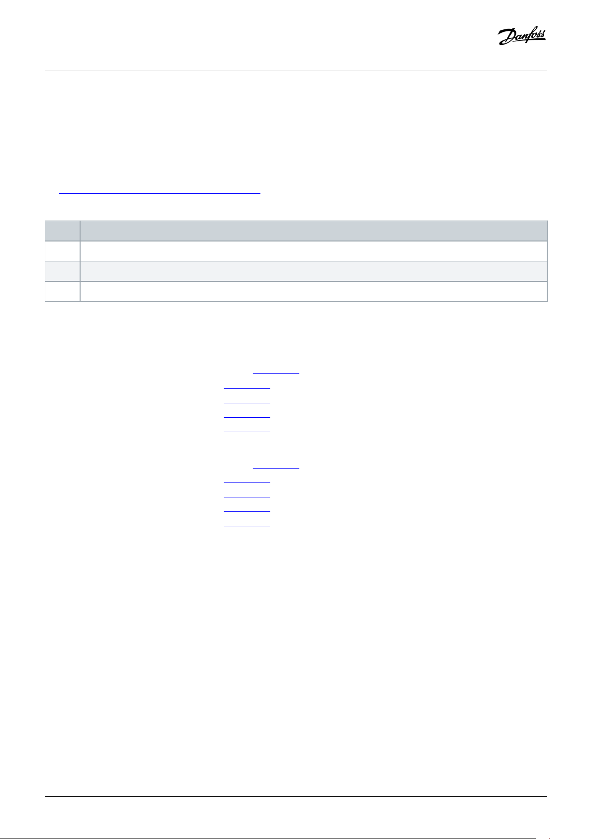
6.6 Over Load Protection
6.6.1 Function Description
The over load protection function protects the DC cables. The function is based on an internal counter. The counter value is increased
when the input current is above the Minimum input level and decreased when below the value. The increase or decrease occurs every
10 ms.
The over load trip is done when the over load counter value is over 10000.
The parameter Maximum step defines the increase when the input reaches the maximum defined input level (Maximum input). The
minimum and maximum input points also define the slope for the function. For example, if the input current is in the middle of the
minimum and maximum input values, the counter increases by half of the value set with Maximum step parameter.
The over load counter calculation is done individually for each phase.
A Motor current in % of the nominal current rating
C Minimum input
E Over load trip level
Illustration 31: Example of the Internal Counter Value as a Function of the Motor Current
Example:
Parameter example for tripping at 120% after 20 s:
30 | Danfoss A/S © 2018.10
B Over load counter value
D Maximum input
F Maximum step
AQ284746085202en-000201 / DPD02123

Operating Guide | VACON® NXP DCGuard™
• P2.8.X.1, X Overload Response = 2
• P2.8.X.2, Minimum Input = 101%
• P2.8.X.3, Maximum Input = 120%
• P2.8.X.4, Maximum Step = 5
Tripping time = 10000 / (P2.8.X.4 x 100) = 10000 / (5 x 100) = 20 s
Parameter Settings
6.6.2 U Phase Over Load Protection
6.6.2.1 (ID 1524) U Over Load Response
Location in the menu: P2.8.2.1
Use this parameter to set the trip response when the over load protection counter is above the tripping limit in phase U.
• 0 = No Action
• 1 = Warning information
• 2 = Fault
Selection 2 gives the fault code F83, U phase over load.
6.6.2.2 (ID 1504) Minimum Input U
Location in the menu: P2.8.2.2
Use this parameter to set the U phase current level in % of the rated current when the over load counter starts to increase.
6.6.2.3 (ID 1505) Maximum Input U
Location in the menu: P2.8.2.3
Use this parameter to set the input value level for phase U where the over load counter is increased with the maximum step defined by
parameter ID 1506.
6.6.2.4 (ID 1506) Maximum Step U
Location in the menu: P2.8.2.4
Use this parameter to set the step in the phase U over load counter when the input value is at the maximum input level defined by
parameter ID 1505.
6.6.3 V Phase Over Load Protection
6.6.3.1 (ID 1525) V Over Load Response
Location in the menu: P2.8.3.1
Use this parameter to set the trip response when the over load protection counter is above the tripping limit in phase V.
Danfoss A/S © 2018.10
AQ284746085202en-000201 / DPD02123 | 31

Operating Guide | VACON® NXP DCGuard™
• 0 = No Action
• 1 = Warning information
• 2 = Fault
Selection 2 gives the fault code F84, V phase over load.
Parameter Settings
6.6.3.2 (ID 1531) Minimum Input V
Location in the menu: P2.8.3.2
Use this parameter to set the V phase current level in % of the rated current when the over load counter starts to increase.
6.6.3.3 (ID 1532) Maximum Input V
Location in the menu: P2.8.3.3
Use this parameter to set the input value level for phase V where the over load counter is increased with the maximum step defined by
parameter ID 1533.
6.6.3.4 (ID 1533) Maximum Step V
Location in the menu: P2.8.3.4
Use this parameter to set the step in the phase V over load counter when the input value is at the maximum input level defined by
parameter ID 1532.
6.6.4 W Phase Over Load Protection
6.6.4.1 (ID 1526) W Over Load Response
Location in the menu: P2.8.4.1
Use this parameter to set the trip response when the over load protection counter is above the tripping limit in phase W.
• 0 = No Action
• 1 = Warning information
• 2 = Fault
Selection 2 gives the fault code F85, W phase over load.
6.6.4.2 (ID 1534) Minimum Input W
Location in the menu: P2.8.4.2
Use this parameter to set the W phase current level in % of the rated current when the over load counter starts to increase.
32 | Danfoss A/S © 2018.10
AQ284746085202en-000201 / DPD02123

Operating Guide | VACON® NXP DCGuard™
Parameter Settings
6.6.4.3 (ID 1535) Maximum Input W
Location in the menu: P2.8.4.3
Use this parameter to set the input value level for phase W where the over load counter is increased with the maximum step defined
by parameter ID 1536.
6.6.4.4 (ID 1536) Maximum Step W
Location in the menu: P2.8.4.4
Use this parameter to set the step in the phase W over load counter when the input value is at the maximum input level defined by
parameter ID 1535.
6.7 Controlled Voltage Ramp-Up
6.7.1 (ID 601) Switching Frequency
Location in the menu: P2.5.1
Use this parameter to set the switching frequency for the controlled ramp up of the voltage in the DC cables out of the DCGuard. The
switching frequency is used only during the charging procedure. The default setting is 5.0 kHz.
6.7.2 (ID 606) Pulse Ratio
Location in the menu: P2.5.2
Use this parameter to set the minimum pulse ratio for charging the DC link of the DCGuard peer-to-peer connection. The charging is
started with a certain minimum voltage, not from zero voltage.
6.7.3 (ID 1541) Voltage Rise Time
Location in the menu: P2.5.3
Use this parameter to set the voltage rise time to full DC-link voltage in the bus tie cables. The recommended voltage rise time is 200–
400 ms.
Danfoss A/S © 2018.10
AQ284746085202en-000201 / DPD02123 | 33

Operating Guide | VACON® NXP DCGuard™
Index
Index
A
Approvals and certifications 5
C
Cabling
Cabling (ID 1503)
Control I/O 23
Controlled voltage ramp-up
10
25
D
Disposal 5
F
Functional description 8
H
High current cut-off
27
I
I/O configuration 23
Instant current cut-off
Intended use 8
26
Purpose of the manual 5
Q
Qualified personnel 5
R
Rapid current cut-off 26
9
S
Safety
SW trip response (ID 1874) 27
Switching frequency (ID 601) 33
T
Terminals
U
U high current response (ID 1550)
U over load response (ID 1524)
U phase trip limit (ID 1500) 26
U trip delay (ID 1552)
U trip limit (ID 1551) 28
7
16
28
31
28
M
Maximum input U (ID 1505)
Maximum input V (ID 1532) 32
Maximum input W (ID 1535)
Maximum step U (ID 1506) 31
Maximum step V (ID 1533)
Maximum step W (ID 1536) 33
Minimum input U (ID 1504) 31
Minimum input V (ID 1531)
Minimum input W (ID 1534) 32
31
33
32
32
O
Over load protection
Overview
30
P
Parameters 25
Protection functions
Pulse ratio (ID 606) 33
V
V high current response (ID 1553)
V over load response (ID 1525) 31
V phase trip limit (ID 1501)
V trip delay (ID 1555) 29
V trip limit (ID 1554)
Voltage rise time (ID 1541) 33
W
W high current response (ID 1556)
W over load response (ID 1526) 32
W phase trip limit (ID 1502)
W trip delay (ID 1559) 30
W trip limit (ID 1558)
8
Wiring diagrams
Air-cooled inverter units
Liquid-cooled inverter units 13
8
28
26
29
29
27
29
10
34 | Danfoss A/S © 2018.10
AQ284746085202en-000201 / DPD02123

Operating Guide | VACON® NXP DCGuard™
Danfoss A/S © 2018.10
AQ284746085202en-000201 / DPD02123 | 35

Danfoss can accept no responsibility for possible errors in catalogues, brochures and other printed material. Danfoss reserves the right to alter its products without notice. This also applies to products
already on order provided that such alterations can be made without subsequential changes being necessary in specifications already agreed. All trademarks in this material are property of the respective
companies. Danfoss and the Danfoss logotype are trademarks of Danfoss A/S. All rights reserved.
Vacon Ltd
Member of the Danfoss Group
Runsorintie 7
65380 Vaasa
Finland
drives.danfoss.com
Danfoss A/S © 2018.10
DPD02123B
DOC-OGDCGUARD+DLUK
 Loading...