

Page 1

vacon® nx
ac drives
optc6
canopen option board
user manual
Page 2

Page 3

1
Local contacts: http://drives.danfoss.com/danfoss-drives/local-contacts/
INDEX Document code: DPD00896B
Date: 24.08.2017
1. GENERAL ........................................................................................................................... 2
2. CANOPEN OPTION BOARD TECHNICAL DATA .................................................................... 3
2.1 General ..................................................................................................................................... 3
2.2 CANopen cable ......................................................................................................................... 3
3. CANOPEN ........................................................................................................................... 4
4. CANOPEN OPTION BOARD LAYOUT AND CONNECTIONS .................................................. 5
4.1 CANopen option board ............................................................................................................. 5
4.2 Bus terminal resistors ............................................................................................................. 5
4.3 LED indications ......................................................................................................................... 6
4.4 Connection of CANopen bus cable ........................................................................................... 7
5. INSTALLATION OF VACON® NX CANOPEN BOARD ........................................................... 12
5.1 Board information sticker ...................................................................................................... 14
6. COMMISSIONING .............................................................................................................. 15
7. CANOPEN- VACON® NX INTERFACE................................................................................. 19
7.1 CANopen message frame ...................................................................................................... 19
7.2 Network Management (NMT) ................................................................................................. 21
7.3 Process data (PDO) ................................................................................................................. 22
7.4 Transmission types ................................................................................................................ 23
7.5 Controlling the drive via PDO messages with Drive Profile ................................................... 24
7.6 Using manufacturer specific PDOs with ByPass modes ................................ ........................ 27
7.7 Drive Monitoring ..................................................................................................................... 29
7.8 Anyparameter service ............................................................................................................ 30
8. Service Data (SDO) ........................................................................................................... 31
9. Node Guarding Protocol ................................................................................................... 44
10. Electronic Data Sheet, EDS-file ....................................................................................... 45
11. APPENDICES .................................................................................................................... 46
appendix a - device profile for drives ..................................................................................................... 46
appendix b sdo messages .................................................................................................................... 47
appendix c process data contents ....................................................................................................... 48
appendix d .............................................................................................................................................. 49
Page 4
2 GENERAL
Local contacts: http://drives.danfoss.com/danfoss-drives/local-contacts/
1
1. GENERAL VACON
®
NX AC drives can be connected to the CANopen system using a fieldbus board. The AC drive
can then be controlled, monitored and programmed from the Host system.
The CANopen fieldbus board is installed in slot D or slot E on the control board of the AC drive.
DANGER
Internal components and circuit boards are at high potential when the AC drive is
connected to the power source. This voltage is extremely dangerous and may
cause death or severe injury if you come into contact with it.
NOTE! When experiencing problems with fieldbus functionalities, always write down all the texts and
codes on the keypad display. Then send the problem description together with the Drive Info File to
the local distributor. See local contacts: http://drives.danfoss.com/danfoss-drives/local-contacts/ .
NOTE! You can download the English and French product manuals with applicable safety, warning
and caution information from http://drives.danfoss.com/knowledge-center/technical-
documentation/.
REMARQUE Vous pouvez télécharger les versions anglaise et française des manuels produit
sur le site http://drives.danfoss.com/knowledge-center/technical-documentation/.
Page 5
CANOPEN OPTION BOARD TECHNICAL DATA 3
Local contacts: http://drives.danfoss.com/danfoss-drives/local-contacts/
2
2. CANOPEN OPTION BOARD TECHNICAL DATA
2.1 General
CANopen
connections
Interface
Open Style Connector (Pluggable connector, 5.08mm)
Data transfer
method
CAN (ISO 11898)
Transfer cable
2 wire twisted shielded cable
Electrical isolation
500 VDC
Communications
CANopen
CiA DS-301
CiA DSP-402
Baud rate
10 kBaud
20 kBaud
50 kBaud
100 kBaud
125 kBaud
250 kBaud
500 kBaud
1000 kBaud
Addresses
1 127
Environment
The specifications of the drive are applicable.
Safety
Fulfils EN50178 standard
Table 2-1. CANopen technical data
2.2 CANopen cable According to the ISO 11898 standard, cables to be chosen for CAN bus lines should have a nominal
impedance of 120, and a specific line delay of nominal 5 ns/m. Line termination has to be provided
through termination resistors of 120 located at both ends of the line. The length related resistance
should have 70 m/m. All these mentioned AC and DC parameters are suitable for a 1 Mbit/s
transmission rate.
The table below shows practical bus length for CANopen networks with less than 64 nodes:
Baudrate [Kbit/s]
Max. Bus length [m]
1000
30
800
50
500
100
250
250
125
500
50
1000
20
2500
Page 6

4 CANOPEN
Local contacts: http://drives.danfoss.com/danfoss-drives/local-contacts/
3
3. CANOPEN CANopen is a networking system based on the serial bus Controller Area Network (CAN). The
CANopen Communication Profile (CiA DS-301) supports both direct access to device parameters and
time-critical process data communication. CANopen device profiles (CiA DS-40x) define standards for
basic device functionality while providing ample scope for additional vendor-specific device features.
CANopen leashes the full power of CAN by allowing direct peer to peer data exchange between nodes
in an organised and, if necessary, deterministic manner. The network management functions
specified in CANopen simplify project design, implementation and diagnosis by providing standard
mechanisms for network start-up and error management.
CANopen supports both-cyclic and event-driven communication. This makes it possible to reduce the
bus load to a minimum but still maintaining extremely short reaction times. High communication
performance can be achieved at relatively low baud rates, thus reducing EMC problems and
minimising cable costs.
CANopen is the ideal networking system for all types of automated machinery. One of the
distinguishing features of CANopen is its support for data exchange at the supervisory control level as
well as accommodating the integration of very small sensors and actuators on the same physical
network. This avoids the unnecessary expense of gateways linking sensor/actuator bus systems with
higher communication networks and makes CANopen particularly attractive to original equipment
manufacturers.
Device Profile Drives and Motion Control (CiA DSP-402)
document represents the standardised
CANopen Device Profile for digital controlled motion products like servo controllers, AC drives or
stepper motors. All the above-mentioned devices use communication techniques which conform to
those described in the CANopen Application Layer and Communication Profile. The starting and
stopping of the drive and several mode specific commands are executed by the statemachine. The
operation mode defines the behaviour of the drive. The following modes are defined in this profile:
Homing Mode
Profile Position Mode
Interpolated Position Mode
Profile Velocity Mode
Profile Torque Mode
Velocity Mode
VACON
®
CANopen Option Board supports the Velocity Mode
Page 7
CANOPEN OPTION BOARD LAYOUT AND CONNECTIONS 5
Local contacts: http://drives.danfoss.com/danfoss-drives/local-contacts/
4
4. CANOPEN OPTION BOARD LAYOUT AND CONNECTIONS
VACON
®
CANopen Board is connected to the fieldbus through a 5-pin pluggable bus connector (board
NXOPTC6).
The communication with the control board of the AC drive takes place through the standard VACON
®
Interface Board Connector.
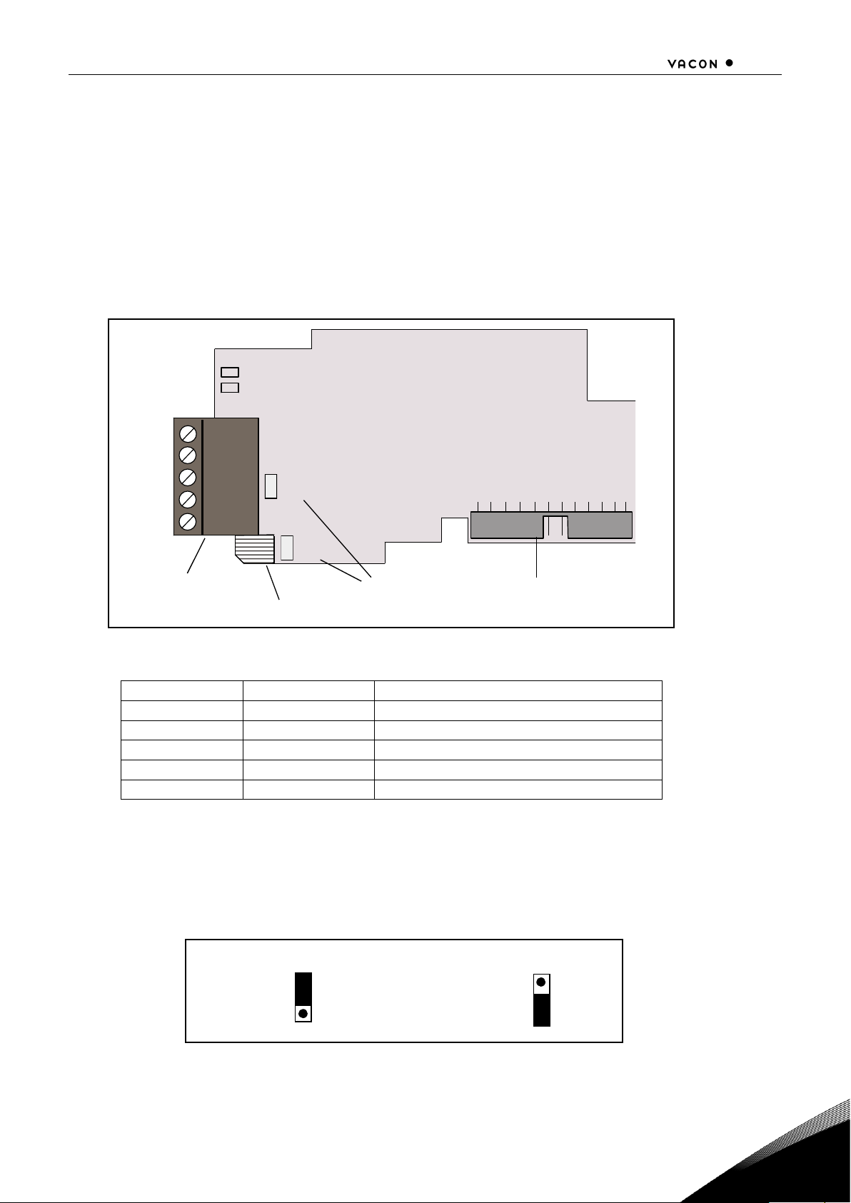
4.1 CANopen option board
Figure 4-1. VACON
®
CANopen option board OPT-C6
Signal
Connector
Description
CAN_GND
1
Ground / 0V / V-
CAN_L
2
CAN_L bus line (dominant low)
(CAN_SHLD)
3
Optional CAN shield
CAN_H
4
CAN_H bus line (dominant high)
(CAN_V+)
5
-
Table 4-1.OPT-C6 bus connector signals
4.2 Bus terminal resistors If VACON
®
drive is the last device of the CANopen line the bus termination must be set. Use jumper
X6 (ON position see Figure 4-1), or an external resistor (120) connected to terminals 2 and 4.
ON OFF
X1
A
M
X6
Jumpers
Interface board
connector
Grounding plate
Bus connector
1
2
3
4
5
Page 8
6 CANOPEN OPTION BOARD LAYOUT AND CONNECTIONS
Local contacts: http://drives.danfoss.com/danfoss-drives/local-contacts/
4
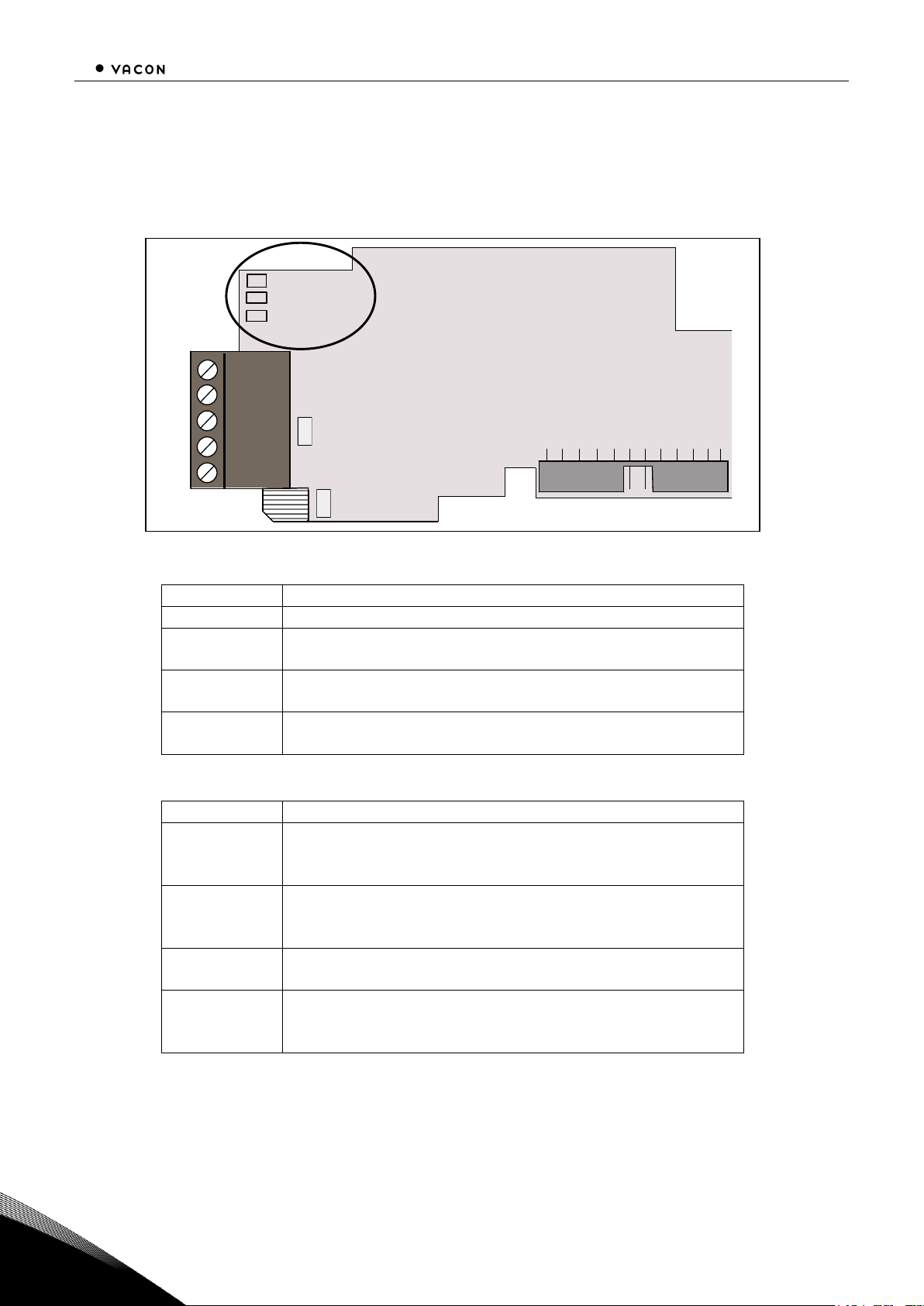
4.3 LED indications The CANopen Option Board includes two LED status indicators next to the connector: Fieldbus status
(M), CANopen(A). Led N is unused.
Figure 4-2. LED indications on the CANopen board
CANopen board status LED (A) GREEN
LED is:
Meaning:
OFF
Option board not activated
ON
Option board in initialisation state waiting for activation
command from the AC drive
Blinking fast
(1 blink / s)
Option board is activated and in RUN state
Option board is ready for external communication
Blinking slow
(1 blink/ 5s)
Option board is activated and in FAULT state
Internal fault of option board
Fieldbus status LED (M) GREEN
LED is:
Meaning:
OFF
Fieldbus module is waiting for parameters from the AC
drive
No external communication
ON
Fieldbus module is activated
Parameters received and module activated
Module is waiting for messages from the bus
Blinking fast
(1 blink / s)
Module is activated and receiving messages from the bus
Blinking slow
(1 blink / 5s)
Module is in FAULT state
No messages from Master within the watchdog time
Bus broken, cable loose or Master off line
X1
A
M
X6
N
Green
Green
Not used
1
2
3
4
5
Page 9
CANOPEN OPTION BOARD LAYOUT AND CONNECTIONS 7
Local contacts: http://drives.danfoss.com/danfoss-drives/local-contacts/
4
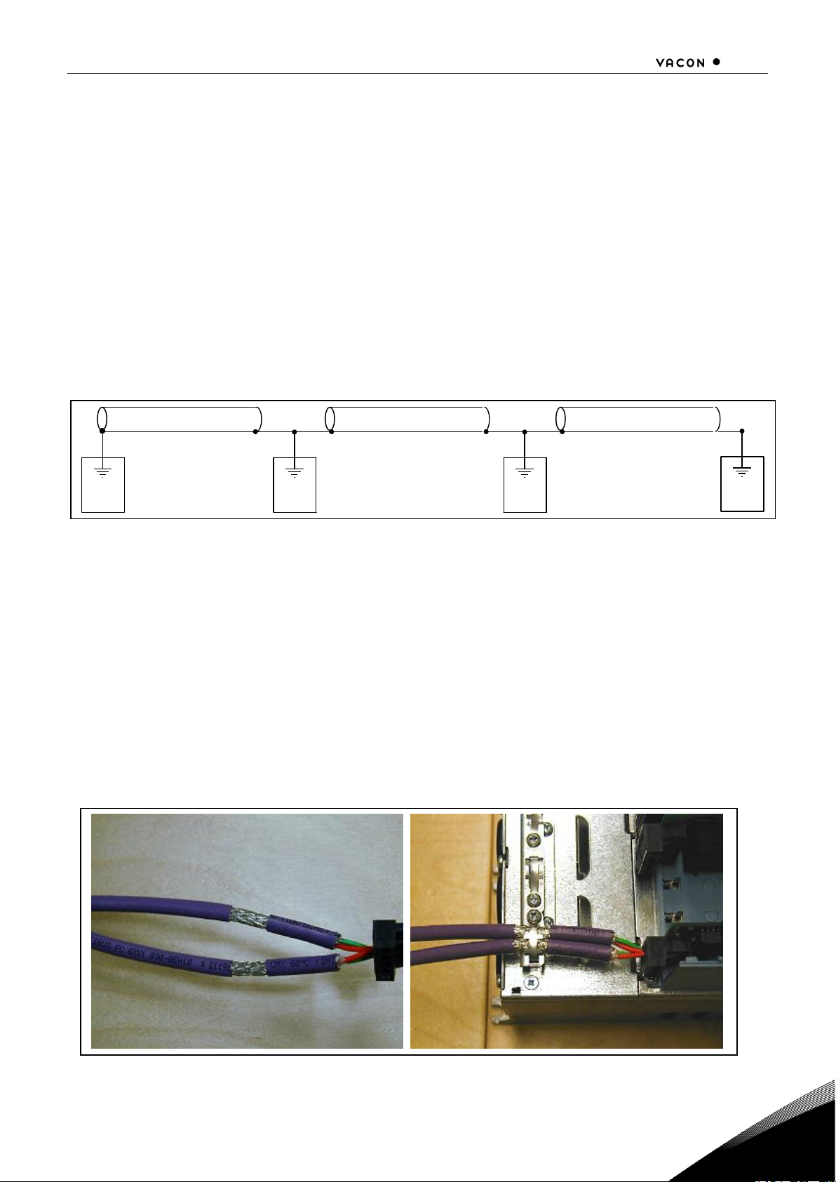
4.4 Connection of CANopen bus cable The bus cable shield can be grounded in three different ways:
a) clamping the cable to the AC drive frame
b) to the frame of the AC drive through an RC filter
c) directly to the AC drive frame
Note: Normally, the option board has already been installed in slot E of the control board. It is not
necessary to detach the whole board for the grounding of the bus cable shield. Just detach the
terminal block.
4.4.1
Grounding by clamping the cable to the AC drive frame
This manner of grounding is the most effective and especially recommended when the distances
between the devices are relatively short (see 4.4.2.1).
In this manner of grounding, the position of jumper X1 is of no importance
Figure 4-3. Grounding by clamping the cable to the AC drive frame
1 Strip about 5 cm of the CANopen cable in the same way as shown in Figure 4-4 but cut off the
grey cable shield.
Remember to do this for both bus cables (except for the last device).
2 Leave no more than 1 cm of the data cable outside the terminal block and strip the data cables at
about 0.5 cm to fit in the terminals. See Figures 4-5 and 4-6.
Note: Do this for both bus cabels
3 Insert the data cables of both CANopen cables into terminals #2 and #4. See Figure 4-7.
4 Strip the CANopen cable at such a distance from the terminal that you can fix it to the frame with
the grounding clamp.
Figure 4-4.
c a b l e
c a b l e c a b l e
C a n p e n O
C a n p e n O C a n p e n
O
Page 10
8 CANOPEN OPTION BOARD LAYOUT AND CONNECTIONS
Local contacts: http://drives.danfoss.com/danfoss-drives/local-contacts/
4
4.4.2
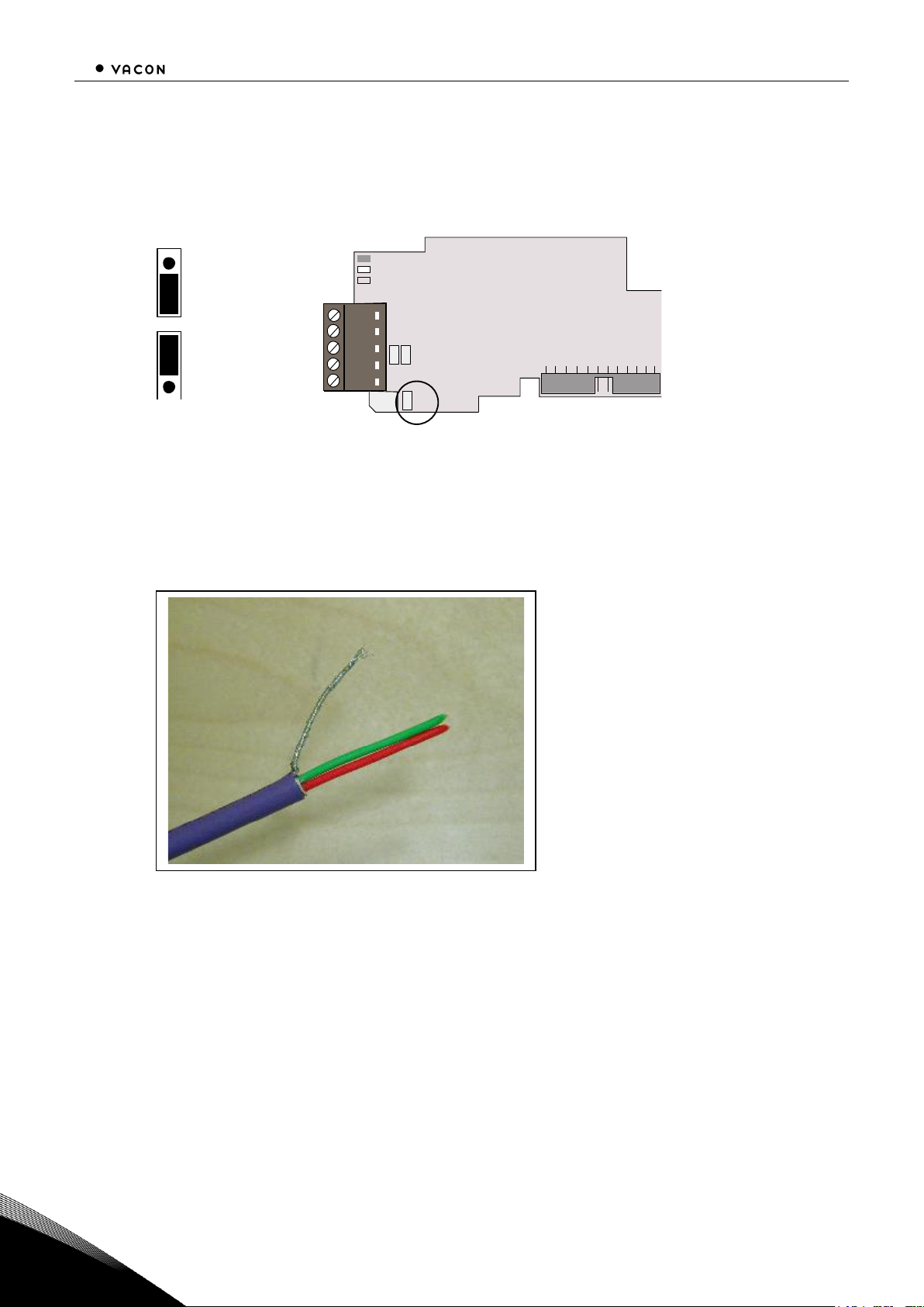
Grounding the bus cable shield directly to the AC drive frame using jumper X1
1 Set jumper X1 in ON position:
Figure 4-5. Jumper X1 positions
2 Strip about 5 cm of the CANopen cable as shown in the picture.
Note: Do the same for both bus cables (except for the last device). However, since the
grounding must be done on one cable only cut off the exposed part of the other grounding
cable.
Figure 4-6.
3 Leave no more than 1 cm of the red and green data cable outside the terminal block and
strip the data cables at about 0.5 cm to fit in the terminals. See pictures below.
Note: Do this for both bus cabels.
ON
OFF
X1
Page 11
CANOPEN OPTION BOARD LAYOUT AND CONNECTIONS 9
Local contacts: http://drives.danfoss.com/danfoss-drives/local-contacts/
4
Figure 4-7.
Figure 4-8.
Page 12
10 CANOPEN OPTION BOARD LAYOUT AND CONNECTIONS
Local contacts: http://drives.danfoss.com/danfoss-drives/local-contacts/
4
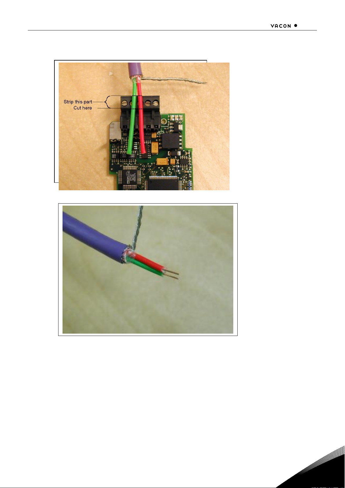
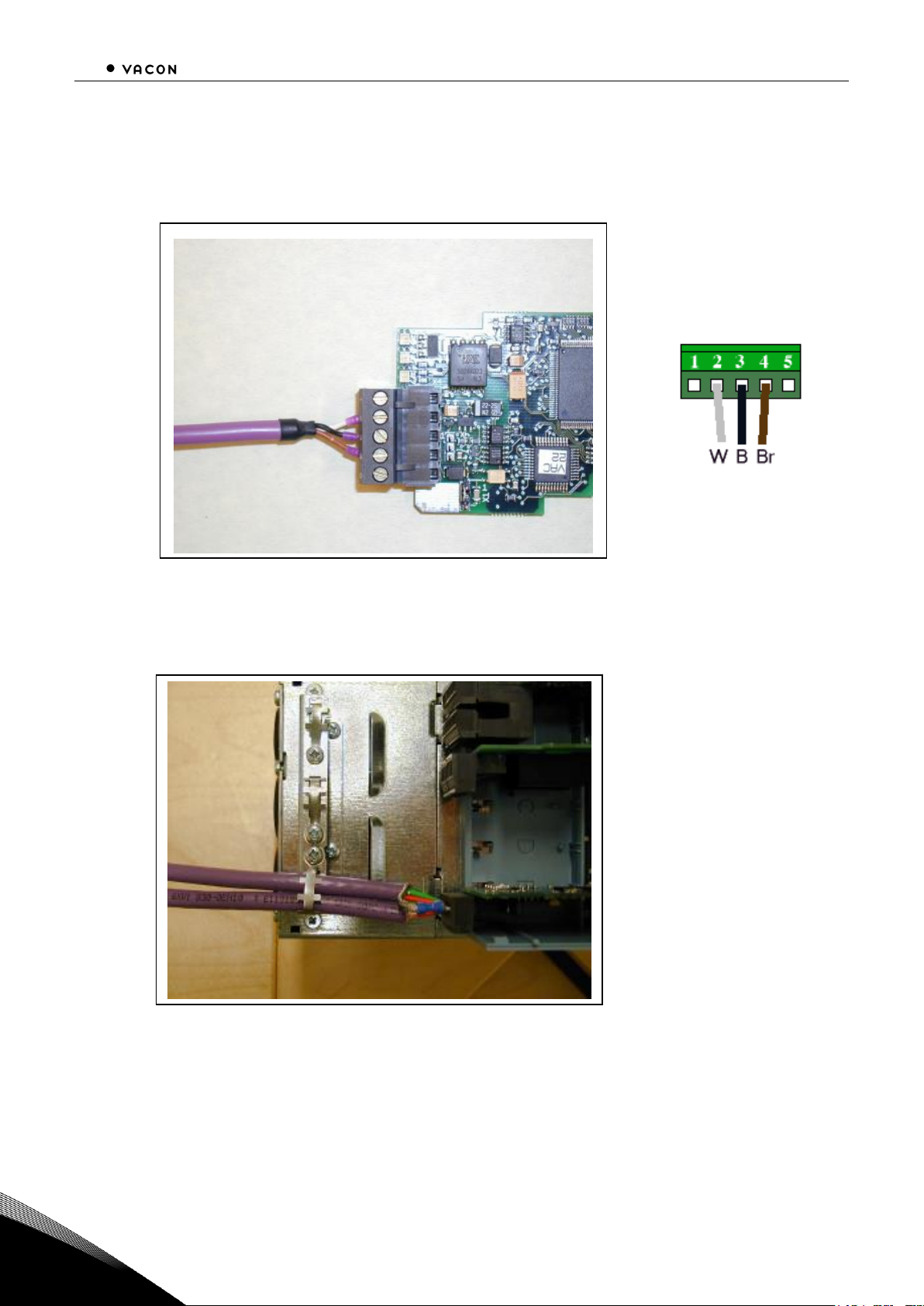
4 We recommend you to use an Abico connector to fit the grounding cable into the grounding
terminal (#3).
Insert the white and brown data cables of both CANopen cables into terminals #2 (white)
and #4 (brown).
Figure 4-9.
5 Place the CANopen board into slot E of the control board (see board installation on page 12)
and fix both the CANopen cables on the frame with the clamp.
Figure 4-10.
Page 13

CANOPEN OPTION BOARD LAYOUT AND CONNECTIONS 11
Local contacts: http://drives.danfoss.com/danfoss-drives/local-contacts/
4
4.4.2.1 Grounding the bus cable shield directly to the AC drive frame using an RC-filter
We recommend you to do the grounding in this manner when the distance between the devices
exceeds 50 meters (55 yds.). When the distance between the devices is long disturbances (e.g. voltage
spikes) are more likely to appear. In this grounding method, the disturbances are filtered out. Even if
the ground planes of A, B and C are different (which is very typical e.g. in construction) there is no
current between them because the points do not have a ground connection.
Figure 4-11. Grounding with RC filter
1 Set jumper X1 in OFF position
Figure 4-12. Jumper X1 positions
2 Carry out the grounding in the same way as advised in Chapter 4.4.1.
C a n O p e n c a b l e
c a b l e c a b l e
A B C
C a n p e n O C a n p e n
O
X1
A
M
ON
OFF
1
2
3
4
5
Page 14
12 INSTALLATION OF VACON® NX CANOPEN BOARD
Local contacts: http://drives.danfoss.com/danfoss-drives/local-contacts/
5
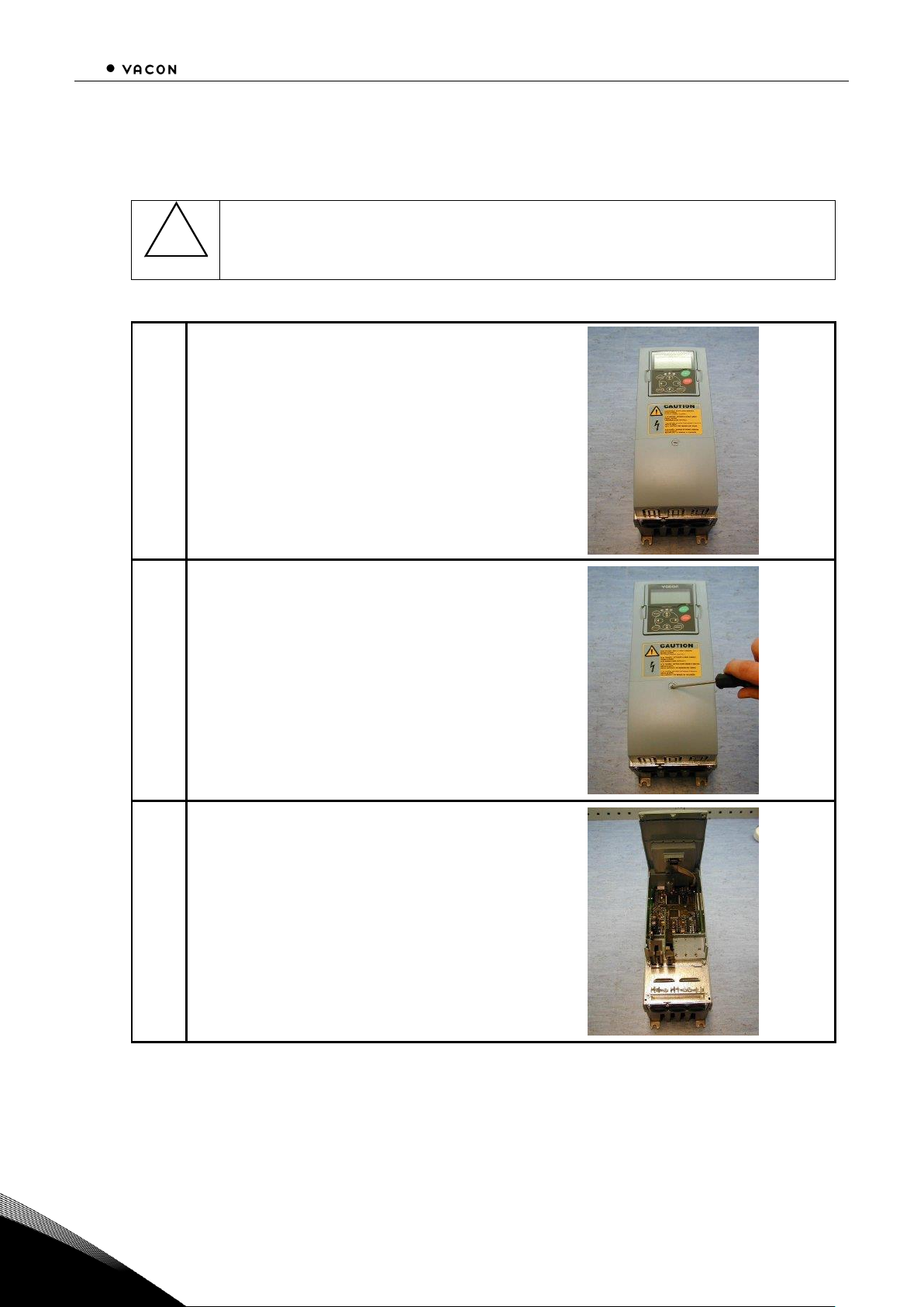
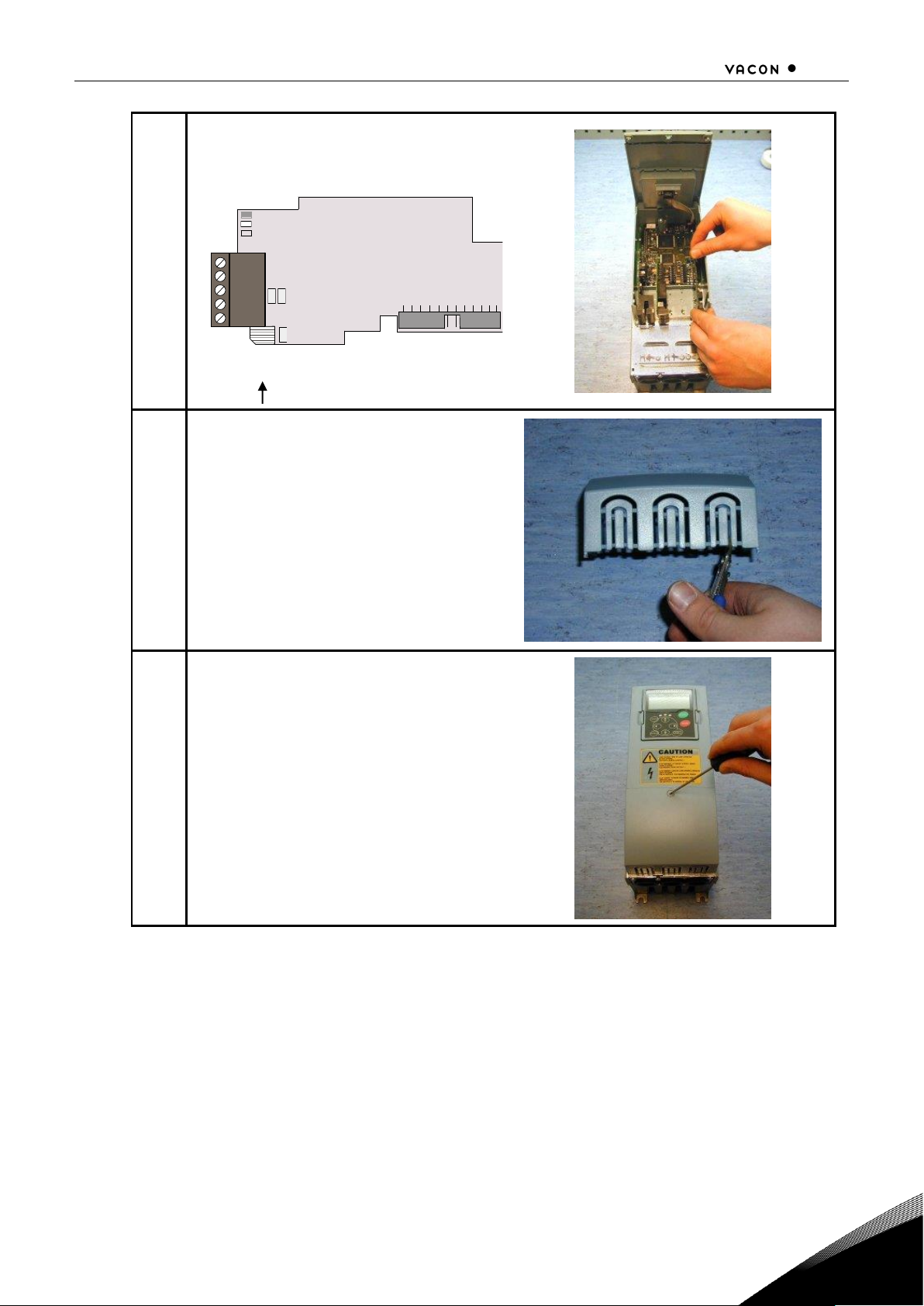
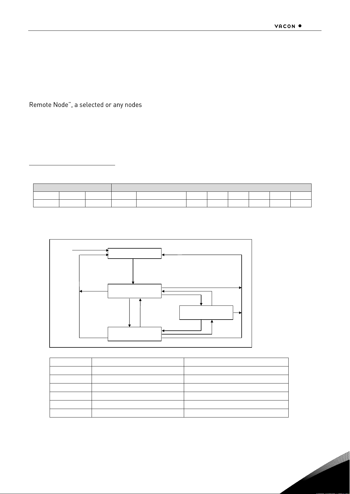
5. INSTALLATION OF VACON® NX CANOPEN BOARD
!
NOTE
MAKE SURE THAT THE AC DRIVE IS SWITCHED OFF BEFORE AN OPTION OR
FIELDBUS BOARD IS CHANGED OR ADDED!
A
VACON
®
NX AC drive
B
Remove the cable cover.
C
Open the cover of the control unit.
Page 15
INSTALLATION OF VACON® NX CANOPEN BOARD 13
Local contacts: http://drives.danfoss.com/danfoss-drives/local-contacts/
5
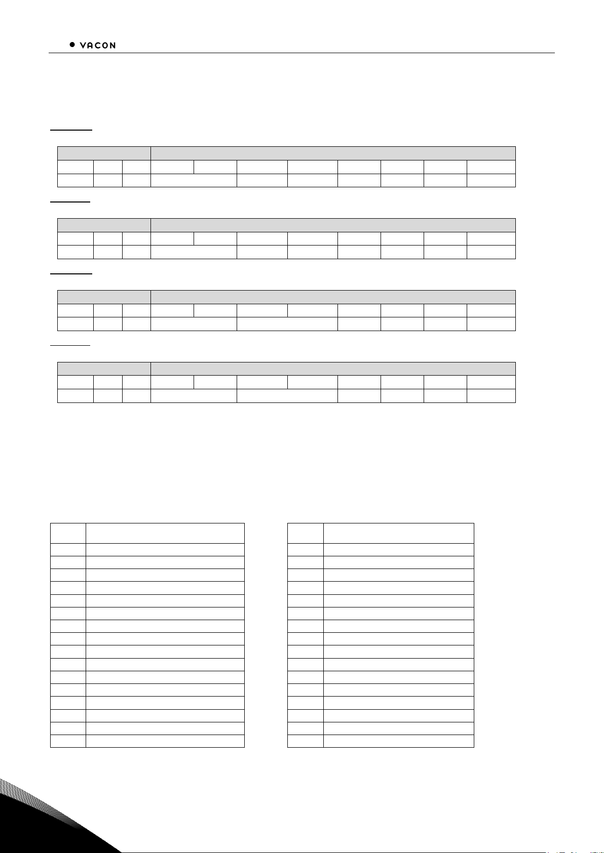
D
Install CANopen option board in slot E
on the control board of the AC drive.
Make sure that the grounding plate (see
below) fits tightly in the clamp.
X6
X1
1
2
3
4
5
E
Make a sufficiently wide opening for
your cable by cutting the grid as wide as
necessary.
F
Close the cover of the control unit and
the cable cover.
Page 16

14 INSTALLATION OF VACON® NX CANOPEN BOARD
Local contacts: http://drives.danfoss.com/danfoss-drives/local-contacts/
5
5.1 Board information sticker The CANopen option board package delivered by the factory includes a sticker (shown below). Please
mark the board type (1), the slot into which the board is mounted (2) and the mounting date (3) on the
sticker. Finally, attach the sticker on your drive.
Drive modified
:
Option board:
NXOPT................
IP54 upgrade/ Collar
in slot:
Date:...................
A B C D E
EMC level modified: H
T / T H
Date:...................
Date:...................
1
2
3
Page 17

COMMISSIONING 15
Local contacts: http://drives.danfoss.com/danfoss-drives/local-contacts/
6
6. COMMISSIONING
READ FIRST CHAPTER 'COMMISSIONING' IN VACON
®
NX USER'S MANUAL VACON
®
NXS NXP Air-
cooled User Manual" or VACON® NXL User's Manual", go to http://drives.danfoss.com/knowledge-
center/technical-documentation/).
Note! You must select Fieldbus as the active control place, if you wish to control the AC drive through
fieldbus. See VACON
®
NX User Manual.
The VACON
®
CANopen board is commissioned with the control keypad by giving values to appropriate
parameters in menu M7 (for locating the expander board menu see VACON
®
NX User Manual.
Expander board menu (M7)
The
Expander board menu
makes it possible for the user 1) to see what expander boards are
connected to the control board and 2) to reach and edit the parameters associated with the expander
board.
Enter the following menu level (G#) with the
Menu button right
. At this level, you can browse through
slots A to E with the
Browser buttons
to see what expander boards are connected. On the lowermost
line of the display you also see the number of parameter groups associated with the board.
If you still press the
Menu button right
once you will reach the parameter group level where there are
two groups: Editable parameters and Monitored values. A further press on the
Menu button right
takes you to either of these groups.
CANopen parameters
To commission the CANopen board, enter the level P7.5.1.# from the
Parameters
group (G7.5.1). Give
desired values to all CANopen parameters.
Figure 6-1. Changing the CANopen option board parameters
G1G5
READY
E:NXOPTC6
READY
G1G2
READY
READY
enter
P1P3
READY
Expander boards
Parameters
Node ID
63
CHANGE VALUE
CONFIRM CHANGE
63
Node ID
Page 18

16 COMMISSIONING
Local contacts: http://drives.danfoss.com/danfoss-drives/local-contacts/
6
#
Name
Default
Range
Description
1
Node ID
1
1 127
2
BAUD RATE
6
1 10 kBaud
2 20 kBaud
3 50 kBaud
4 100 kBaud
5 125 kBaud
6 250 kBaud
7 500 kBaud
8 1000 kBaud
Communication speed
3
Operate mode
1
1 Drive Profile
2 ByPass
3 ByPass 2
4 Bypass 3
5 Bypass 4
Communication set selection
1 = xPDO1, xPDO6
2 = xPDO1, xPDO21, xPDO22
3 = xPDO1, xPDO21, xPDO22
4 = xPDO1, xPDO21, xPDO22,
xPDO23
5 = xPDO1, xPDO21, xPDO22,
xPDO23
Table 6-1. CANopen parameters
NOTE! Bypass modes 3 and 4 require OPTC6 V26 firmware or newer. See VACON
®
NX control
firmware requirements below.
Bypass and Bypass 3 modes can be used in customer-specific applications and in special
applications, such as System Interface application.
Bypass 2 and Bypass 4 modes are used with standard applications, e.g. VACON
®
NXL Multicontrol
application and VACON
®
All-in-One applications for VACON® NXS and NXP.
ByPass 2 mode is supported in the following System software versions:
• NXL NXL00005V253
• NXS NXS00001V174
• NXP NXP00002V174
ByPass 3 and 4 mode are supported in the following System software versions:
• NXP NXP00002V194
The parameters of every device must be set before connecting to the bus. Especially the parameters
ation.
CANopen status
To see the present status of the CANopen Fieldbus, enter the
CANopen Status
page from
Monitor
menu (G7.5.2)
. See picture and table below.
Page 19

COMMISSIONING 17
Local contacts: http://drives.danfoss.com/danfoss-drives/local-contacts/
6
Figure 6-2. DeviceNet status
M o n i t o r
R E A D Y
I / O t e r m
V
1 V
1
C A N i o p e
n s t a t u s
R E A D Y
I / O t e r m
2 5 .
0
M e s s a g e c o u n t e r
CANopen
s t a t u
s
Page 20

18 COMMISSIONING
Local contacts: http://drives.danfoss.com/danfoss-drives/local-contacts/
6
CANopen status
0
INITIALISING
4
STOPPED
5
OPERATIONAL
6
PRE_OPERATIONAL
7
RESET_APPLICATION
8
RESET_COMM
9
UNKNOWN
Table 6-2. CANopen status indications
Page 21

CANOPEN- VACON® NX INTERFACE 19
Local contacts: http://drives.danfoss.com/danfoss-drives/local-contacts/
7
7. CANOPEN- VACON
®
NX INTERFACE
CANopen communication objects transmitted via the CAN network are described by services and
protocols. They are classified as follows:
- The real-time data transfer is performed by the Process Data Objects (PDOs) protocol
REAL-TIME CONTROL OF THE DRIVE
- Service Data Objects (SDO) protocols provide the read and write access to entries of a device
object dictionary
CONFIGURATION OF THE DRIVE, READ/WRITE DRIVE PARAMETERS
- The Network Management (NMT) protocols provide services for network initialization, error
control and device status control
START/STOP CANOPEN COMMUNICATION
7.1 CANopen message frame
SOF
COB-ID
RTR
CTRL
Data Segment
CRC
ACK
EOF
1bit
11bit
1bit
5bit
0-8bytes
16bits
2bits
7bits
SOF Start of Frame CRC Cyclic Redundancy Check
RTR Remote Transmission Request ACK Acknowledge
CTRL Control Field (i.e. Data Length) EOF End of Frame
COB-ID
The identification field of the CANopen-message is 11 bits.
ID-Bit
10 9 8 7 6 5 4 3 2 1 0
COB-ID
Function Code
Module-ID
The default identification field consists of a functional part and a module-ID part. The functional part
determines the object priority. This kind of identification field allows communication between a
master and 127 slaves. Broadcasting is indicated by a module-id of zero. Function codes are
determined with object dictionaries in device profiles.
Page 22

20 CANOPEN- VACON® NX INTERFACE
Local contacts: http://drives.danfoss.com/danfoss-drives/local-contacts/
7
Predefined connection sets
CANopen option board has two different communication parameter sets. These sets can be selected
via Operate Mode
-profile described in CiA DSP-402.
Drive Profile - mode
Object
Function Code
(binary)
COB-ID
Comm. parameter at Index
NMT message
0000
0x0000
-
Sync Message
0001
0x0080
0x1005
Time-Stamp-Message
0001
0x0100
-
PDO1, Process Data Objects (tx)
0011
0x0180 +Node
0x1800
PDO1, Process Data Objects (rx)
0100
0x0200 +Node
0x1400
PDO6, Process Data Objects (tx)
0101
0x0280 +Node
0x1801
PDO6, Process Data Objects (rx)
0110
0x0300 +Node
0x1401
SDO, Service Data Objects (tx)
1011
0x0580 +Node
SDO, Service Data Objects (rx)
1100
0x0600 +Node
Node Guarding
1110
0x0700 +Node
(0x100E)
Table 7-1. Drive Profile -mode
ByPass - mode
Object
Function Code
(binary)
COB-ID
Comm. parameter at Index
NMT message
0000
0x0000
-
Sync Message
0001
0x0080
0x1005
Time-Stamp-Message
0010
0x0100
-
PDO1, Process Data Objects (tx)
0011
0x0180 +Node
0x1800
PDO1, Process Data Objects (rx)
0100
0x0200 +Node
0x1400
PDO21, Process Data Objects (tx)
0111
0x0380 +Node
0x1814
PDO21, Process Data Objects (rx)
1000
0x0400 +Node
0x1414
PDO22, Process Data Objects (tx)
1001
0x0480 +Node
0x1815
PDO22, Process Data Objects (rx)
1010
0x0500 +Node
0x1415
PDO23, Process Data Objects (tx)
0101
0x280 +Node
0x1816
PDO23, Process Data Objects (rx)
0110
0x300 +Node
0x1416
SDO, Service Data Objects (tx)
1011
0x0580 +Node
SDO, Service Data Objects (rx)
1100
0x0600 +Node
Node Guarding
1110
0x0700 +Node
(0x100E)
Table 7-2. Bypass -mode
Page 23
CANOPEN- VACON® NX INTERFACE 21
Local contacts: http://drives.danfoss.com/danfoss-drives/local-contacts/
7
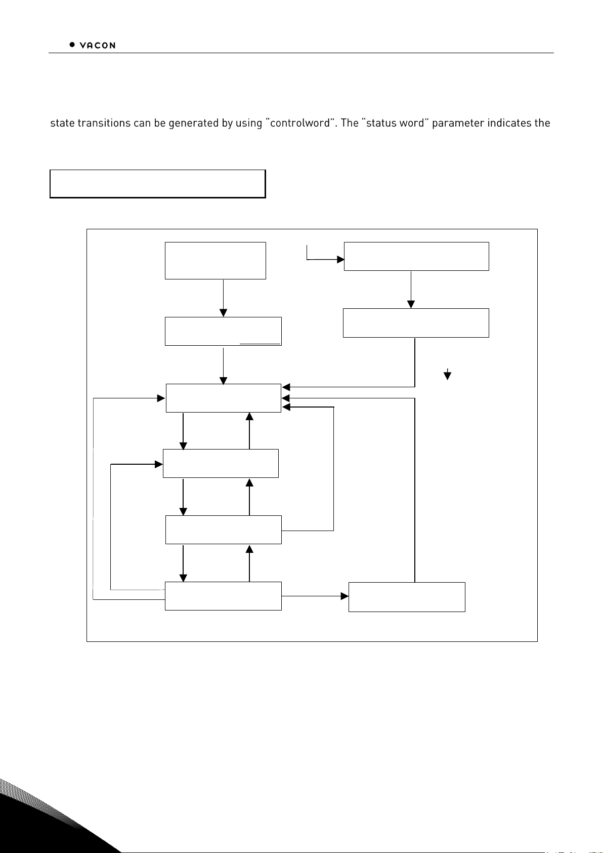
7.2 Network Management (NMT) The CANopen network management is node-oriented and follows a master/slave structure. It
requires one device in the network, which fulfills the function of the NMT master. The other nodes are
NMT slaves.
The CANopen NMT slave devices implement a state machine, see picture below. After power on a
node initialises and transits to the "Pre-operational State". In this state communication across SDO
channels is possible for node configuration, but not yet across PDOs. With the NMT message "Start
on the network can be set into the "Operational State". In this
state, also the exchange of data by means of PDOs is possible. With enabling the operation of all
nodes of a network at the same time, a co-ordinated operation of the communicating system is
secured (DS301).
To Set VACON
®
CANopen Option board to the "Operational State" the following message must be
sent:
Message: Start_Remote_Node
Master to Slave (1)
Header
Data
ID
RTR
Len
1 = CS
2 = Node ID
3 4 5 6 7 8 0000 0 2
01
01
Function of the internal state machine:
Change
Message / Event
Command Specifier (CS)
1
Start Remote Node
CS = 1
2
Stop Remote Node
CS = 2
3
Enter Pre-operational State
CS = 128
4
Reset Node
CS = 129
5
Reset Communication
CS = 130
6
Initialisation finished
Automatic
Initialization
Pre-Operational
Prepared
Operational
Power
On
6
4
5
1
3
2
3
1
2
Page 24

22 CANOPEN- VACON® NX INTERFACE
Local contacts: http://drives.danfoss.com/danfoss-drives/local-contacts/
7
7.3 Process data (PDO)
The realPDOs is performed with no protocol overhead. Process Data is time-critical data used for control of
the drive and monitor status of the drive. Transmit PDOs support several transmission modes which
are cyclic, acyclic, synchronous, asynchronous and RTR only mode. Most PDOs support also Event
Timer for transmitting PDOs. TPDO1 is exception which is defined for asynchronous only operation.
Receive PDOs support only asynchronous transmission mode (event driven). VACON
®
CANopen
option board uses 8 types of PDOs as follows:
Cyclic Acyclic Synchronous
Asynchronous
(default
RTR Only mode Event Timer
PDO
Type
Mapped Data
Mapped Data
Mapped Data
Mapped Data
TPDO1
statusword
- - - x
TPDO6
statusword
vl_control_effort
- - X X X x X
X
TPDO21
nx_status_word
nx_actual_speed
process_data_out
1
process_data_out
2
X X X x X
X
TPDO22
process_data_out3
process_data_out4
process_data_out5
process_data_out6
X X X x X X RPDO1
controlword
- - - x
RPDO6
controlword
vl_target_velocity
- - x RPDO21
nx_control_word
nx_speed_reference
process_data_in1
process_data_in2
x RPDO22
process_data_in3
process_data_in4
process_data_in5
process_data_in6
x
Note: manufacturer specific PDOs (TPDO21/RPDO21/ TPDO22/RPDO22) consist of application specific
process data. See appendix for contents of these process datas in different applications. See Chapter
7.6 (Using manufacturer specific PDOs) or a specific application manual.
Note! All Tx objects are event-driven by default. (Message is sent out if one or several values within
the message change)
Page 25

CANOPEN- VACON® NX INTERFACE 23
Local contacts: http://drives.danfoss.com/danfoss-drives/local-contacts/
7
7.4 Transmission types
transmission type
PDO transmission
cyclic
acyclic
synchronou
s
asynchronou
s
RTR only
0 X X
1-240 X X
241-251
- Reserved -
252 X
X
253 X
X
254 X
255 X
Table 7-3. Description of transmission type
Synchronous (transmission types 0-240 and 252) means that the transmission of the PDO shall be
related to the SYNC object. Preferably the devices use the SYNC as a trigger to output or actuate
based on the previous synchronous Receive PDO respectively to update the data transmitted at the
following synchronous Transmit PDO. Asynchronous means that the transmission of the PDO is not
related to the SYNC object. A transmission type of zero means that the message shall be transmitted
synchronously with the SYNC object but not periodically. A value between 1 and 240 means that the
PDO is transferred synchronously and cyclically. The transmission type indicating the number of
SYNC which are necessary to trigger PDO transmissions. Receive PDOs are always triggered by the
following SYNC upon reception of data independent of the transmission types 0 - 240.
The transmission types 252 and 253 mean that the PDO is only transmitted on remote transmission
request. At transmission type 252, the data is updated (but not sent) immediately after reception of
the SYNC object. At transmission type 253 the data is updated at the reception of the remote
transmission request (hardware and software restrictions may apply). These value are only possible
for TPDOs. For TPDOs transmission type 254 means, the application event is manufacturer specific
(manufacturer specific part of the Object Dictionary), transmission type 255 means, that the
application event is defined in the device profile. RPDOs with that type trigger the update of the
mapped data with the reception. PDOs Sub-index 3h contains the inhibit time. This time is a minimum
interval for PDO transmission. The value is defined as multiple of 100 s. It is not allowed to change
the value while the PDO exists (Bit 31 of sub-index 1 is 0).
In mode 254/255 additionally an event time can be used for TPDO. If an event timer exists for a TPDO
(value not equal to 0) the elapsed timer is considered to be an event. The event timer elapses as
multiple of 1 ms of the entry in sub-index 5h of the TPDO. This event will cause the transmission of
this TPDO in addition to otherwise defined events. The occurrence of the events set the timer.
Independent of the transmission type the RPDO event timer is used recognize the expiration of the
RPDO.
Page 26
24 CANOPEN- VACON® NX INTERFACE
Local contacts: http://drives.danfoss.com/danfoss-drives/local-contacts/
7
7.5 Controlling the drive via PDO messages with Drive Profile
PDO1 Rx
Master to Slave (1)
Header
Data
ID
RTR
Len 1 2 3 4 5 6 7 8
0x201
0
2
controlword
- - - - -
-
PDO1 Tx
Slave (1) to Master
Header
Data
ID
RTR
Len 1 2 3 4 5 6 7 8
0x181
0
2
statusword
- - - - -
-
PDO6 Rx
Master to Slave (1)
Header
Data
ID
RTR
Len 1 2 3 4 5 6 7 8
0x301
0
4
controlword
vl_target_velocity
- - -
-
PDO6 Tx
Slave (1) to Master
Header
Data
ID
RTR
Len 1 2 3 4 5 6 7 8
0x281
0
4
statusword
vl_control_effort
- - -
-
The state of the drive can be controlled by the
controlword
The state of the drive is shown in the
statusword.
The
Statemachine
describes the device status and the possible control sequence of the drive.
controlword
statusword
bit
Name
bit
Name
0
Switch ON
0 Ready to Switch ON
1
Disable Voltage
1 Switched ON
2
Quick Stop
2 Operation Enable
3
Enable Operation
3 Fault
4
Operation Mode Specific
4 Voltage Disable
5
Operation Mode Specific
5 Quick Stop
6
Operation Mode Specific
6 Swich ON Disable
7
Reset Fault
7 Warning
8
Halt
8 Manufacturer Specific
9
Reserved
9 Remote
10
Reserved
10
Target Reached
11
Manufacturer Specific
11
Internal Limit Active
12
Manufacturer Specific
12
Operation Mode Specific
13
Manufacturer Specific
13
Operation Mode Specific
14
Manufacturer Specific
14
Manufacturer Specific
15
Manufacturer Specific
15
Manufacturer Specific
Page 27

CANOPEN- VACON® NX INTERFACE 25
Local contacts: http://drives.danfoss.com/danfoss-drives/local-contacts/
7
By using a control word the drive can be controlled as follows:
Command
ControlWord
Description
Prepare READY
0006hex
Prepare RUN
0007hex
RUN
000Fhex
he active control
place
STOP
0007hex
Stop motor
FAULT RESET (step 1)
FAULT RESET (step 2)
bit 7 = 0
bit 7 = 1
Rising edge to bit 7
vl_target_velocity
The vl_target_velocity is the required speed reference to the AC drive.
The unit is RPM.
vl_control_effort
The vl_control_effort is the actual speed of the motor.
The unit is RPM.
Page 28
26 CANOPEN- VACON® NX INTERFACE
Local contacts: http://drives.danfoss.com/danfoss-drives/local-contacts/
7
State Machine
The state machine describes the device status and the possible control sequence of the drive. The
current status of state machine. The modes
INIT, STOP, RUN
and
FAULT
correspond to the actual
mode of the Drive.
SW = StatusWord
CW = ControlWord word
MALFUNCTION
FAULT
SW:xx08h or xx28h
MALFUNCTION REACTION ACTIVE
FAULT
SW:xxxFh or xx2Fh
QUICK STOP ACTIVE
STOP
SW:xx07h
READY TO SWITCH ON
STOP
SWITCH ON DISABLED
STOP
SW:xx40h or xx60h
NOT READY TO SWITCH ON
IN IT
SW:xx00h
Power ON
OPERATION ENABLED
RUN
SW:xx27h
SWITCHED ON
STOP
SW: xx23h
Reset malfunction
CW: 0000h
CW: 0002h
CW: 0006h
CW: 0006h
CW: 0007h
CW: 0007h
CW: 000Fh
CW: 0006h
Automatic
Automatic
Automatic
Fault
CW: 0080h
CW: 0002h
CW: 000Dh
CW: 0003h
SW:xx21h
Page 29

CANOPEN- VACON® NX INTERFACE 27
Local contacts: http://drives.danfoss.com/danfoss-drives/local-contacts/
7
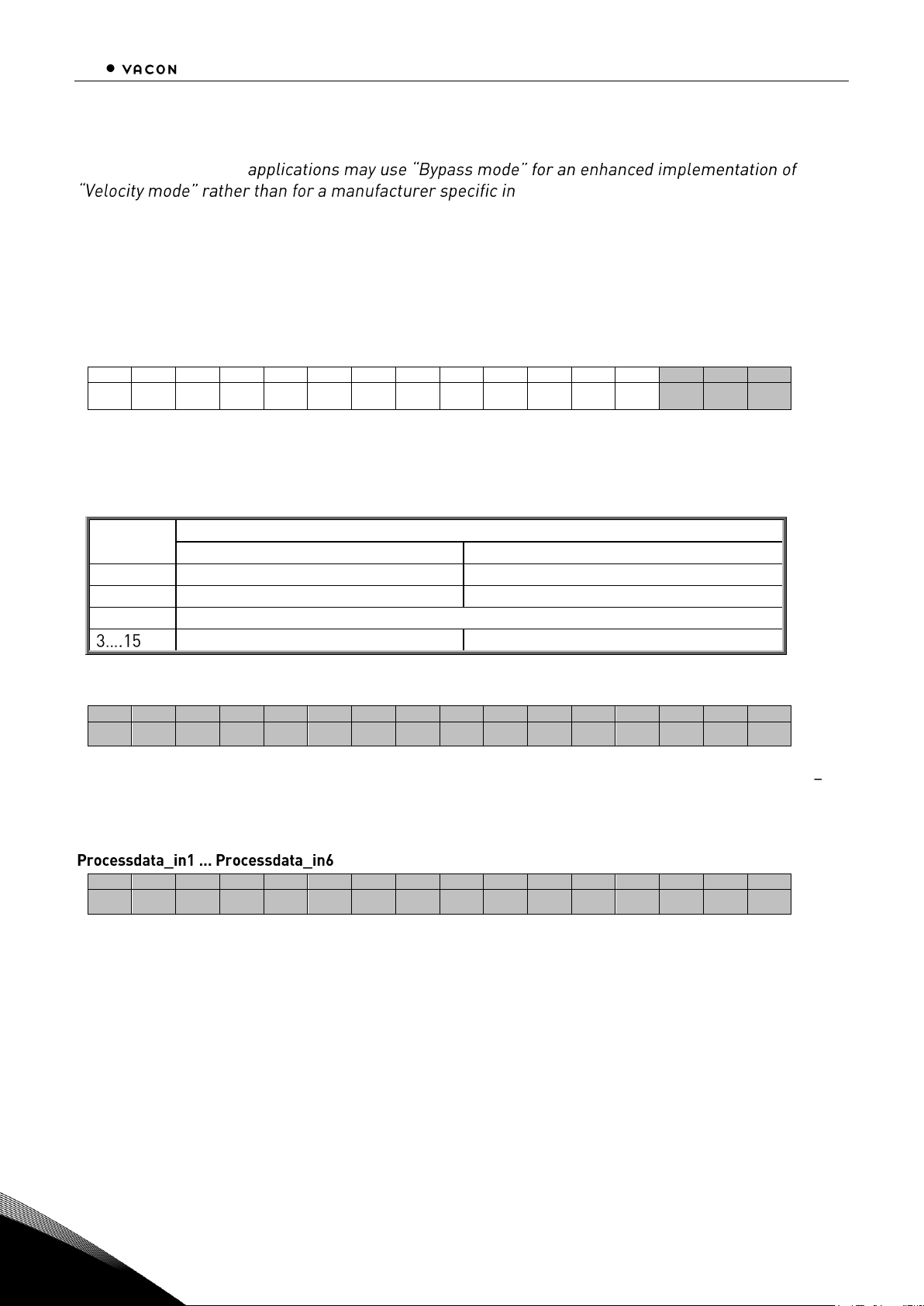
7.6 Using manufacturer specific PDOs with ByPass modes
any Bypass
mode. For communication set used in ByPass modes, see Table 7-2. Manufacturer specific PDOs are
TPDO21, TPDO22, TPDO23, RPDO21, RPDO22 and RPDO23.
PDO21 Rx
Master to Slave (1)
Header
Data
ID
RTR
Len 1 2 3 4 5 6 7 8
0x401
0
8
nx_control_word
nx_speed_referense
process_data_in1
process_data_in2
PDO21 Tx
Slave (1) to Master
Header
Data
ID
RTR
Len 1 2 3 4 5 6 7 8
0x381
0
8
nx_status_word
nx_actual_speed
process_data_out1
process_data_out2
PDO22 Rx
Master to Slave (1)
Header
Data
ID
RTR
Len 1 2 3 4 5 6 7 8
0x501
0
8
process_data_in3
process_data_in4
process_data_in5
process_data_in6
PDO22 Tx
Slave (1) to Master
Header
Data
ID
RTR
Len 1 2 3 4 5 6 7 8
0x481
0
8
process_data_out3
process_data_out4
process_data_out5
process_data_out6
PDO23 Rx
Master to Slave (1)
Header
Data
ID
RTR
Len 1 2 3 4 5 6 7 8
0x301
0
4
process_data_in7
process_data_in8
-
-
TDO23 Tx
Slave (1) to Master
Header
Data
ID
RTR
Len 1 2 3 4 5 6 7 8
0x281
0
4
process_data_out7
process_data_out8
-
-
Page 30
28 CANOPEN- VACON® NX INTERFACE
Local contacts: http://drives.danfoss.com/danfoss-drives/local-contacts/
7
Controlling drive
NOTE: Some
VACON
®
terface. Refer to the specific application
manual for details
The Reference to the drive can be set also via manufacturer specific Process Data Object 21 (rx) when
option board is set to Bypass mode. In the application, the value is scaled in percentage of frequency
area between the set minimum and maximum frequencies.
nx_control_word, used only with Bypass 2 or Bypass 4 mode. When Bypass or Bypass 3 modes are used, check more detailed Control Word in the application manual
15
14
13
12
11
10 9 8 7 6 5 4 3 2 1 0
- - - - - - - - - - - - -
RST
DIR
RUN
In VACON
®
applications, the three first bits of the control word are used to control the AC drive.
However, you can customise the content of the control word for your own applications because the
control word is sent to the AC drive as such.
Bit
Description
Value = 0
Value = 1
0
Stop
Run
1
Clockwise
Counter clockwise
2
Rising edge of this bit will reset active fault
Not in use
Not in use
nx_speed_reference
15
14
13
12
11
10 9 8 7 6 5 4 3 2 1 0
MSB
LSB
This is the Reference 1 to the AC drive. Used normally as Speed reference. The allowed scaling is
10000...10000. In the application, the value is scaled in percentage of the frequency area between the
set minimum and maximum frequencies.
15
14
13
12
11
10 9 8 7 6 5 4 3 2 1 0
MSB
LSB
These are application specific process data. See APPENDIX C for content of these process data in
different applications.
Page 31

CANOPEN- VACON® NX INTERFACE 29
Local contacts: http://drives.danfoss.com/danfoss-drives/local-contacts/
7
7.7 Drive Monitoring Several drive actual values/parameters can be monitored by using manufacturer specific PDOs.
nx_speed_reference
15
14
13
12
11
10 9 8 7 6 5 4 3 2 1 0
MSB
LSB
This is the reference 1 to the AC drive. Used normally as Speed reference.
The allowed scaling is 0..10000. In the application, the value is scaled in percentage of the frequency
area between set minimum and maximum frequency.
nx_status_word, used only Bypass 2 or Bypass 4 mode. When Bypass or Bypass 3 modes are used, check more detailed Status Word in the application manual
15
14
13
12
11
10 9 8 7 6 5 4 3 2 1 0
- - - - -
UVFS
DDIR
TCSPDL
FR Z AREF W FLT
DIR
RUN
RDY
Information about the status of the device and messages is indicated in the
Status word
. The
Status
word
is composed of 16 bits that have the following meanings:
Bit
Description
Value = 0
Value = 1
0
Not Ready
Ready
1
STOP
RUN
2
Clockwise
Counterclockwise
3
-
Faulted
4 - Warning
5
Ref. frequency not reached
Ref. Frequency reached
6 - Motor is running at zero speed
7
Flux Ready
Flux Not Ready
8
TC Speed Limit Active (depends on drive
model)
TC Speed Limit Not Active (depends on
drive model)
9
Detected Encoder Direction Clockwise
(depends on drive model)
Encoder Direction Counterclockwise
(depends on drive model)
10
UV Fast Stop Active (depends on drive
model)
UV Fast Stop Not Active (depends on drive
model)
11...15
Not In use
Not In use
Table 7-4. Status word bit descriptions
15
14
13
12
11
10 9 8 7 6 5 4 3 2 1 0
MSB
LSB
These are application specific process data. See APPENDIX C for content of these process data in
different applications.
Page 32

30 CANOPEN- VACON® NX INTERFACE
Local contacts: http://drives.danfoss.com/danfoss-drives/local-contacts/
7
7.8 Anyparameter service SDO protocol can be used to read any parameter or actual value and write any parameter from drive.
These parameters are read from drive with its ID number specified in user manual. There are three
index in object dictionary as follow for anyparameter service.
Inde
x
Description
Size
Type
Hi 16b
Low 16b
2000
AnyparameterReadID
U16
RW - Read ID
2001
AnyparameterReadV
alue
U32
RO
Status
Value
2002
AnyparameterWrite
U32
RW
ID
Write Value
Reading anyparameter
Writing new value to index 2000 will trigger read event, while read is in process index 2001 is zero.
Read event will return value to index 2001. If read is success status will get value of ID and Value is
value of ID. If read fails Status will get value 0xFFFF (dec 65535).
Writing anyparameter
When new ID and value is written to index 2002 a write event will be triggered. Index 2002 value will
remain as long as writing is processed (normal sdo/pdo operation during this time). If write is success
index 2002 ID and value will be cleared and new write is possible. If write fails ID will clamp to 0xFFFF
and value zero.
Figure 7-1. Reading Any Parameter
Figure 7-2. Writing Any Parameter
Write ID with SDO protocol
0x0066
Index 2000
Index 2001
Read value with SDO protocol
0xFFFF 0x0000 = Fail
ID Value = OK
0x000 0x0000 = In process
16bit
16bi
16bit
.
. 100ms delay for read event
.
0x0066
0x0032
Status
Value
Write ID and value with SDO
protocol
Index 2002
Index 2002
Read write event status
0x0000 0x0000 = OK,
0xFFFF 0x0000 = Fail
0x0066 0x003c = In Process
16bi
16bit
.
. 100ms delay for write event
.
0x0000
0x0000
Status
16bi
16bit
0x0066
0x003C
ID
Value
Read ID
Page 33

Service Data (SDO) 31
Local contacts: http://drives.danfoss.com/danfoss-drives/local-contacts/
8
8. SERVICE DATA (SDO)
With service Data Objects (SDOs) the access to entries of a device Object Dictionary is provided. Via
SDO all items from object dictionary can be read/written.
Service Data Objects (SDO)s are normally used for device configuration such as setting device
parameters. They are also used to define the type and format of information communicated using the
Process Data Objects. CANopen Configuration tools with EDS-files can be used for that purpose. The
construction and the method of operation of the SDOs can be found in the CANopen (DS301)
Communication Profile document. Appendix B consist of short description of the SDOs used with
VACON
®
CANopen option Board.
Object Dictionary
Index
Name
Type
Attr.
hex
dec
1000
4096
device_type
Unsigned32
CO
1001
4097
error_register
Unsigned8
RO
1003
4099
predefined error field
Unsigned32
RO
1005
4101
cob-id sync message
Unsigned32
RO
100C
4108
guard_time
Unsigned32
RW
100D
4109
life_time_factor
Unsigned32
RW
1018
4120
Identity Object
Identity
1200
4608
1st_server_SDO_parameter
SDOParameter
1400
5120
1st_receive_PDO_parameter
PDOCommPar
1405
5125
6st_receive_PDO_parameter
PDOCommPar
1414
5140
21st_receive_PDO_parameter
PDOCommPar
1415
5141
22st_receive_PDO_parameter
PDOCommPar
1600
5632
1st_receive_PDO_mapping
PDOMapping
1605
5637
6st_receive_PDO_mapping
PDOMapping
1614
5652
21st_receive_PDO_mapping
PDOMapping
1615
5653
22st_receive_PDO_mapping
PDOMapping
1800
6144
1st_transmit_PDO_parameter
PDOCommPar
1805
6149
6nd_transmit_PDO_parameter
PDOCommPar
1814
6164
21nd_transmit_PDO_parameter
PDOCommPar
1815
6165
22nd_transmit_PDO_parameter
PDOCommPar
1A00
6656
1st_transmit_PDO_mapping
PDOMapping
1A05
6661
6st_transmit_PDO_mapping
PDOMapping
1A14
6676
21st_transmit_PDO_mapping
PDOMapping
1A15
6677
22st_transmit_PDO_mapping
PDOMapping
2000
8192
AnyParameterReadID
Integer16
RW
2001
8193
AnyParameterReadValue
Integer32
RO
2002
8194
AnyParameterWrite
Integer32
RW
2003
8195
nx_current_percentage
Integer16
RO
2004
8196
nx_torque_percentage
Integer16
RO
2063
8291
nx_fault_code
Integer16
RO
27D1
10193
NX control word
Integer16
RW
27D3
10195
NX speed reference
Integer16
RW
27D4
10196
Process data in1
Integer16
RW
27D5
10197
Process data in2
Integer16
RW
27D6
10198
Process data in3
Integer16
RW
27D7
10199
Process data in4
Integer16
RW
27D8
10200
Process data in5
Integer16
RW
27D9
10201
Process data in6
Integer16
RW
27DA
10202
Process data in7
Integer16
RW
27DB
10203
Process data in8
Integer16
RW
Page 34

32 Service Data (SDO)
Local contacts: http://drives.danfoss.com/danfoss-drives/local-contacts/
8
2836
10294
NX status word
Integer16
RO
2838
10296
NX actual speed
Integer16
RO
2839
10297
Process data out1
Integer16
RO
283A
10298
Process data out2
Integer16
RO
283B
10299
Process data out3
Integer16
RO
283C
10300
Process data out4
Integer16
RO
283D
10301
Process data out5
Integer16
RO
283E
10302
Process data out6
Integer16
RO
283F
10303
Process data out7
Integer16
RO
2840
10304
Process data out8
Integer16
RO
6040
24640
controlword
Unsigned16
RW
6041
24641
statusword
Unsigned16
RO
6042
24642
vl_target_velocity
Integer16
RW
6043
24643
vl_velocity_demand
Integer16
RO
6044
24644
vl_control_effort
Integer16
RO
6046
24646
vl_velocity_min_max_amount
Unsigned32
RW
6048
24648
vl_velocity_acceleration
Ramp
RW
6049
24649
vl_velocity_deceleration
Ramp
RW
604A
24650
vl_velocity_quick_stop
Ramp
RW
604E
24654
vl_velocity_reference
Unsigned32
RW
6060
24672
modes_of_operation
Integer8
RO
6061
24673
modes_of_operation_display
Integer8
RO
Page 35

Service Data (SDO) 33
Local contacts: http://drives.danfoss.com/danfoss-drives/local-contacts/
8
Description of the Object Dictionary
Abbreviations
ro - read only i16 - Integer8
wo - write only i32 - Integer8
rw - read write u8 - Unsigned8
co - constant u16 - Unsigned16
bool - Boolean u32 - Unsigned32
i8 - Integer8 float - Floating Point
Index
(HEX)
SubIndex
Name
Default
Min
Max
Type
Attr.
Descriptions
General Parameters
1000
00
Device Type
0x00010192
0x00000000
0xFFFFFFFF
u32 co
The device type specifies the kind of device. The lower
16 bits contain the device profile number and the upper
16 bits an additional information.
1001
00
Error Register
0x00
0x00
0xFF
u8 ro
The error register is a field of 8 bits, each for a certain
error type. If an error occurs the bit has to be set.
Bit Meaning
0 generic error
1 current
2 voltage
3 temperature
4 communication error (overrun, error state)
5 device profile specific
6 reserved
7 manufacturer specific
1003 Pre-defined Error Field
This object holds errors that have occurred on the device
and have been signalled via Emergency Object. It is an
error history. Writing value 0 to sub index 0 deletes the
entire error history.
00
Number of Errors
0x0000
0x0000
0x00FE
u8 rw
01
Standard Error Field
0x00000000
0x00000000
0xFFFFFFFF
u32 ro
02
Standard Error Field
0x00000000
0x00000000
0xFFFFFFFF
u32 ro
03
Standard Error Field
0x00000000
0x00000000
0xFFFFFFFF
u32 ro
04
Standard Error Field
0x00000000
0x00000000
0xFFFFFFFF
u32 ro
05
Standard Error Field
0x00000000
0x00000000
0xFFFFFFFF
u32 ro
06
Standard Error Field
0x00000000
0x00000000
0xFFFFFFFF
u32 ro
07
Standard Error Field
0x00000000
0x00000000
0xFFFFFFFF
u32 ro
08
Standard Error Field
0x00000000
0x00000000
0xFFFFFFFF
u32 ro
09
Standard Error Field
0x00000000
0x00000000
0xFFFFFFFF
u32 ro
Page 36

34 Service Data (SDO)
Local contacts: http://drives.danfoss.com/danfoss-drives/local-contacts/
8
0A
Standard Error Field
0x00000000
0x00000000
0xFFFFFFFF
u32 ro
1005
00
cob-id sync message
0x80000080
0x00000001
0xFFFFFFFF
u32 ro
cob-id used for synchronize PDO messages
100C
00
Guard Time
0x03E8
0x0000
0xFFFF
u16 rw
This entry contains the guard time in
milliseconds. It is 0, if not used.
Unit: ms
100D
00
Life Time Factor
0x02
0x00
0xFF
u8 rw
The life time factor multiplied with the guard time gives
the life time for the device. It is 0, if not used.
1018 Identity Object
This object contains general information about the
device.
00
Number of entries
0x4
0x1
0x4
u8 ro
01
Vendor Id
0x00000090
0x0
0xFFFFFFFF
u32 ro
Sub-Index 1 contains a unique value allocated each
manufacturer.
02
Product Code
0x00000119
0x0
0xFFFFFFFF
u32 ro
Sub-Index 2 identifies the manufacturer specific product
code (device version).
03
Revision number
0x00000001
0x0
0xFFFFFFFF
u32 ro
Sub-Index 3 contains the revision number. Bit 31-16 is
the major revision number and Bit 15-0 the minor
revision number.
04
Serial number
0x0
0x0
0xFFFFFFFF
u32 ro
Sub-Index 4 identified a manufacturer specific serial
number.
Server SDO Parameters
1200 Server SDO Parameter
The object contains the parameters for the SDOs for
which the device is the server.
00
Number of Entries
0x02 0x02
0x02
u8 ro
01
COB-ID Client -> Server
0x600+NodeID
0x00000601
0xFFFFFFFF
u32 ro
02
COB-ID Server -> Client
0x580+NodeID
0x00000581
0xFFFFFFFF
u32 ro
Receive PDO Communication Parameters
1400 Receive PDO 1
Communication
Parameter
It contains the communication parameters of the first
PDO the device is able to receive.
00
Number of Entries
0x02 0x02
0x05
U8 ro
Sub-index 0 contains the number of PDO-parameters
implemented.
01
COB-ID
0x200+NodeID
0x00000201
0xFFFFFFFF
U32 ro
Sub index 1 describes the COB-ID. If bit 31 is set the PDO
is disabled.
02
Transmission Type
0xFF
0x00
0xFF
u8 ro
The transmission mode is defined by sub-index 2.
Value 0xFF (255) = asynchronous transmission mode (
=event driven )
1405 Receive PDO 6
Communication
Parameter
It contains the communication parameters of the second
PDO the device is able to receive.
00
Number of Entries
0x02 0x02
0x05
u8 ro
Sub-index 0 contains the number of PDO-parameters
implemented.
01
COB-ID
0x300+NodeID
0x00000301
0xFFFFFFFF
u32 ro
Sub index 1 describes the COB-ID. If bit 31 is set the PDO
is disabled.
02
Transmission Type
0xFF
0x00
0xFF
u8 ro
The transmission mode is defined by sub-index 2.
Value 0xFF (255) = asynchronous transmission mode (
=event driven )
Page 37

Service Data (SDO) 35
Local contacts: http://drives.danfoss.com/danfoss-drives/local-contacts/
8
1414 Receive PDO 21
Communication
Parameter
It contains the communication parameters of the
manufacturer specific PDO21 the device is able to
receive.
00
Number of Entries
0x02 0x02
0x05
u8 ro
Sub-index 0 contains the number of PDO-parameters
implemented.
01
COB-ID
0x400+NodeID
0x00000401
0xFFFFFFFF
u32 ro
Sub index 1 describes the COB-ID. If bit 31 is set the
PDO is disabled.
02
Transmission Type
0xFF 0x00
0xFF
u8 ro
The transmission mode is defined by sub-index 2.
Value 0xFF (255) = asynchronous transmission mode (
=event driven )
1415 Receive PDO 22
Communication
Parameter
It contains the communication parameters of the
manufacturer specific PDO22 the device is able to
receive.
00
Number of Entries
0x02 0x02
0x05
u8 ro
Sub-index 0 contains the number of PDO-parameters
implemented.
01
COB-ID
0x500+NodeID
0x00000501
0xFFFFFFFF
u32 ro
Sub index 1 describes the COB-ID. If bit 31 is set the
PDO is disabled.
02
Transmission Type
0xFF 0x00
0xFF
u8 ro
The transmission mode is defined by sub-index 2.
Value 0xFF (255) = asynchronous transmission mode (
=event driven )
1416
Receive PDO 23
Communication
Parameter
It contains the communication parameters of the
manufacturer specific PDO23 the device is able to
receive.
00
Number of Entries
0x02 0x02
0x05
u8 ro
Sub-index 0 contains the number of PDO-parameters
implemented.
01
COB-ID
0x300+NodeID
0x00000301
0xFFFFFFFF
u32 ro
Sub index 1 describes the Cob-ID. If bit 31 is set the
PDO is disabled.
02
Transmission Type
0xFF 0x00
0xFF
u8 ro
The transmission mode is defined by sub-index 2.
Value 0xFF (255) = asynchronous transmission mode (
=event driven )
Receive PDO Mapping Parameters
1600 Receive PDO 1 Mapping
Parameter
It contains the mapping parameters of the first PDO
the device is able to receive.
Sub-index 0 contains the number of the mapped data
objects. All further entries define the data by its index,
sub-index and length.
00
Number of Entries
0x01 0x00
0x40
u8 ro
01
PDO Mapping Entry
0x60400010
0x00000000
0xFFFFFFFF
u32 ro
1605 Receive PDO 6 Mapping
Parameter
It contains the mapping parameters of the PDO6 the
device is able to receive.
Sub-index 0 contains the number of the mapped data
objects. All further entries define the data by its index,
sub-index and length.
00
Number of Entries
0x02
0x0 0x40
u8 ro
01
PDO Mapping Entry
0x60400010
0x00000000
0xFFFFFFFF
u32 ro
02
PDO Mapping Entry
0x60420010
0x00000000
0xFFFFFFFF
u32 ro
1614 Receive PDO 21
Mapping Parameter
It contains the mapping parameters of the PDO21 the
device is able to receive.
Sub-index 0 contains the number of the mapped data
objects. All further entries define the data by its index,
sub-index and length.
00
Number of Entries
0x04
0x00
0x40
u8 ro
01
PDO Mapping Entry
0x27D10010
0x00000000
0xFFFFFFFF
u32 ro
02
PDO Mapping Entry
0x27D30010
u32 ro
Page 38

36 Service Data (SDO)
Local contacts: http://drives.danfoss.com/danfoss-drives/local-contacts/
8
0x00000000
0xFFFFFFFF
03
PDO Mapping Entry
0x27D40010
0x00000000
0xFFFFFFFF
u32 ro
04
PDO Mapping Entry
0x27D50010
0x00000000
0xFFFFFFFF
u32 ro
1615 Receive PDO 22
Mapping Parameter
It contains the mapping parameters of the PDO22 the
device is able to receive.
Sub-index 0 contains the number of the mapped data
objects. All further entries define the data by its index,
sub-index and length.
00
Number of Entries
0x04
0x00
0x40
u8 ro
01
PDO Mapping Entry
0x27D60010
0x00000000
0xFFFFFFFF
u32 ro
02
PDO Mapping Entry
0x27D70010
0x00000000
0xFFFFFFFF
u32 ro
03
PDO Mapping Entry
0x27D80010
0x00000000
0xFFFFFFFF
u32 ro
04
PDO Mapping Entry
0x27D90010
0x00000000
0xFFFFFFFF
u32 ro
1616
Receive PDO 23
Mapping Parameter
It contains the mapping parameters of the PDO23 the
device is able to receive.
Sub-index 0 contains the number of the mapped data
00
Number of Entries
0x02
0x00
0x40
u8 ro
01
PDO Mapping Entry
0x27DA0010
0x00000000
0xFFFFFFFF
u32 ro
02
PDO Mapping Entry
0x27DB0010
0x00000000
0xFFFFFFFF
u32 ro
Transmit PDO Communication Parameters
1800 Transmit PDO 1
Communication
Parameter
It contains the communication parameters of the first
PDO the device is able to transmit.
00
Number of Entries
0x04
0x02
0x05
u8 ro
Sub-index 0 contains the number of PDO-parameters
implemented.
01
COB-ID
0x180+NodeID
0x00000181
0xFFFFFFFF
u32 ro
Sub index 1 describes the COB-ID. If bit 31 is set the
PDO is disabled.
02
Transmission Type
0xFF
0x00
0xFF
u8 ro
The transmission mode is defined by sub-index 2.
Value 0xFF (255) = asynchronous transmission mode (
=event driven )
03
Inhibit Time
0x03E8
0x0000
0xFFFF
u16 rw
An inhibit time can be defined on sub-index 3 in 100 µs.
This time is minimum interval for PD transmission.
Default 100 ms
04
Compatibility Entry
0x03
0x00
0xFF
u8 ro
1805 Transmit PDO 6
Communication
Parameter
It contains the communication parameters of the PDO
6 the device is able to transmit.
00
Number of Entries
0x05
0x02
0x05
u8 ro
Sub-index 0 contains the number of PDO-parameters
implemented.
01
COB-ID
0x280+NodeID
0x00000281
0xFFFFFFFF
u32 ro
Sub index 1 describes the COB-ID. If bit 31 is set the
PDO is disabled.
02
Transmission Type
0xFF
u8 rw
The transmission mode is defined by sub-index 2.
Page 39

Service Data (SDO) 37
Local contacts: http://drives.danfoss.com/danfoss-drives/local-contacts/
8
0x00
0xFF
Value 0xFF (255) = asynchronous transmission mode (
=event driven )
03
Inhibit Time
0x03E8
0x0000
0xFFFF
u16 rw
An inhibit time can be defined on sub-index 3 in 100 µs.
This time is minimum interval for PD transmission.
Default 100 ms
04
Compatibility Entry
0x03
0x00
0xFF
u8 ro
05
Event Timer
0x0000
0x0000
0xFFFF
u16 rw
Event Time can be define on sub index 5 in 1ms
resolution. This is the time interval PDO will be
transmitted.
Value 0 = Disable Event Timer
1814 Transmit PDO 21
Communication
Parameter
It contains the communication parameters of the PDO
21 the device is able to transmit.
00
Number of Entries
0x05
0x02
0x05
u8 ro
Sub-index 0 contains the number of PDO-parameters
implemented.
01
COB-ID
0x380+NodeID
0x00000381
0xFFFFFFFF
u32 ro
Sub index 1 describes the COB-ID. If bit 31 is set the
PDO is disabled.
02
Transmission Type
0xFF
0x00
0xFF
u8 rw
The transmission mode is defined by sub-index 2.
Value 0xFF (255) = asynchronous transmission mode (
=event driven )
03
Inhibit Time
0x03E8
0x0000
0xFFFF
u16 rw
An inhibit time can be defined on sub-index 3 in 100 µs.
This time is minimum interval for PD transmission.
Default 100 ms
04
Compatibility Entry
0x03
0x00
0xFF
u8 ro
05
Event Timer
0x0000
0x0000
0xFFFF
u16 rw
Event Time can be define on sub index 5 in 1ms
resolution. This is the time interval PDO will be
transmitted.
Value 0 = Disable Event Timer
1815 Transmit PDO 22
Communication
Parameter
It contains the communication parameters of the PDO
22 the device is able to transmit.
00
Number of Entries
0x05
0x02
0x05
u8 ro
Sub-index 0 contains the number of PDO-parameters
implemented.
01
COB-ID
0x480 +
NodeID
0x00000481
0xFFFFFFFF
u32 ro
Sub index 1 describes the COB-ID. If bit 31 is set the
PDO is disabled.
02
Transmission Type
0xFF
0x00
0xFF
u8 rw
The transmission mode is defined by sub-index 2.
Value 0xFF (255) = asynchronous transmission mode (
=event driven )
03
Inhibit Time
0x03E8
0x0000
0xFFFF
u16 rw
An inhibit time can be defined on sub-index 3 in 100 µs.
This time is minimum interval for PD transmission.
Default 100 ms
04
Compatibility Entry
0x03
0x00
0xFF
u8 ro
05
Event Timer
0x0000
0x0000
0xFFFF
u16 rw
Event Time can be define on subindex 5 in 1ms
resolution. This is the time interval PDO will be
transmitted.
Value 0 = Disable Event Timer
1816
Transmit PDO 23
Communication
Parameter
It contains the communication parameters of the PDO
23 the device is able to transmit.
00
Number of Entries
0x05
0x02
0x05
u8 ro
Sub-index 0 contains the number of PDO-parameters
implemented.
01
COB-ID
0x280+NodeID
0x00000281
0xFFFFFFFF
u32 ro
Sub index 1 describes the COB-ID. If bit 31 is set the
PDO is disabled.
02
Transmission Type
0xFF
0x00
0xFF
u8 rw
The transmission mode is defined by sub-index 2.
Value 0xFF (255) = asynchronous transmission mode (
=event driven )
03
Inhibit Time
0x03E8
u16 rw
An inhibit time can be defined on sub-index 3 in 100 µs.
Page 40

38 Service Data (SDO)
Local contacts: http://drives.danfoss.com/danfoss-drives/local-contacts/
8
0x0000
0xFFFF
This time is minimum interval for PD transmission.
Default 100 ms
04
Compatibility Entry
0x03
0x00
0xFF
u8 ro
05
Event Timer
0x0000
0x0000
0xFFFF
u16 rw
Event Time can be define on sub index 5 in 1ms
resolution. This is the time interval PDO will be
transmitted.
Value 0 = Disable Event Timer
Transmit PDO Mapping Parameters
1A00 Transmit PDO 1
Mapping Parameter
It contains the mapping parameter for the PDOs the
device is able to transmit.
Sub-index 0 contains the number of the mapped data
objects. All further entries define the data by its index,
sub-index and length. The structure of a mapping
entry is: index , sub index ,length
00
Number of Entries
0x01 0x00
0x40
u8 ro
01
PDO Mapping Entry
0x60410010
0x00000000
0xFFFFFFFF
u32 ro
1A05 Transmit PDO 6
Mapping Parameter
It contains the mapping parameter for the PDOs the
device is able to transmit.
Sub-index 0 contains the number of the mapped data
objects. All further entries define the data by its index,
sub-index and length. The structure of a mapping
entry is: index, sub index, length
00
Number of Entries
0x02 0x0
0x40
u8 ro
01
PDO Mapping Entry
0x60410010
0x00000000
0xFFFFFFFF
u32 ro
02
PDO Mapping Entry
0x60440010
0x00000000
0xFFFFFFFF
u32 ro
Page 41

Service Data (SDO) 39
Local contacts: http://drives.danfoss.com/danfoss-drives/local-contacts/
8
1A14 Transmit PDO 21
Mapping Parameter
It contains the mapping parameter for the PDOs the
device is able to transmit.
Sub-index 0 contains the number of the mapped data
objects. All further entries define the data by its index,
sub-index and length. The structure of a mapping entry
is: index, sub index, length
00
Number of Entries
0x04
0x00 0x40
u8 ro
01
PDO Mapping Entry
0x28360010
0x00000000
0xFFFFFFFF
u32 ro
02
PDO Mapping Entry
0x28380010
0x00000000
0xFFFFFFFF
u32 ro
03
PDO Mapping Entry
0x28390010
0x00000000
0xFFFFFFFF
u32 ro
04
PDO Mapping Entry
0x283A0010
0x00000000
0xFFFFFFFF
u32 ro
1A15 Transmit PDO 22
Mapping Parameter
It contains the mapping parameter for the PDOs the
device is able to transmit.
Sub-index 0 contains the number of the mapped data
objects. All further entries define the data by its index,
sub-index and length. The structure of a mapping entry
is:
index,sub index,length
00
Number of Entries
0x04
0x00
0x40
u8 ro
01
PDO Mapping Entry
0x283B0010
0x00000000
0xFFFFFFFF
u32 ro
02
PDO Mapping Entry
0x283C0010
0x00000000
0xFFFFFFFF
u32 ro
03
PDO Mapping Entry
0x283D0010
0x00000000
0xFFFFFFFF
u32 ro
04
PDO Mapping Entry
0x283E0010
0x00000000
0xFFFFFFFF
u32 ro
1A16
Transmit PDO 23 Mapping
Parameter
It contains the mapping parameter for the PDOs the
device is able to transmit.
Sub-index 0 contains the number of the mapped data
objects. All further entries define the data by its index,
sub-index and length. The structure of a mapping entry
is: index, sub index, length
00
Number of Entries
0x02
0x00
0x40
u8 ro
01
PDO Mapping Entry
0x283F0010
0x00000000
0xFFFFFFFF
u32 ro
02
PDO Mapping Entry
0x28400010
0x00000000
0xFFFFFFFF
u32 ro
Manufacturer Specific Parameters
2000 AnyParameterReadID
0x0000
0x0000
0xFFFF
u16 rw
Page 42

40 Service Data (SDO)
Local contacts: http://drives.danfoss.com/danfoss-drives/local-contacts/
8
2001 AnyParameterReadValue
0x00000000
0x00000000
0xFFFFFFFF
u32 ro
2002 AnyParameterWrite
0x00000000
0x00000000
0xFFFFFFFF
u32 rw
2003 NX current percentage
0x0000
0x0000
0xFFFF
u16 ro
Measured motor current. (1 = 0.01A)
2004 NX torque percentage
0x0000
0x0000
0xFFFF
u16 ro
Calculated torque. Scaled in 0.0%…100.0% (0…1000)
2063 NX fault code
0x0000
0x0000
0xFFFF
i16 ro
Shows the drive fault code (=0, if no fault active)
27D1 NX control word
0x0000
0x8000
0x7FFF
i16 rw
27D3 NX speed reference
0x0000
0x8000
0x7FFF
i16 rw
27D4 Process Data In1
0x0000
0x8000
0x7FFF
i16 rw
27D5 Process Data In2
0x0000
0x8000
0x7FFF
i16 rw
27D6 Process Data In3
0x0000
0x8000
0x7FFF
i16 rw
27D7 Process Data In4
0x0000
0x8000
0x7FFF
i16 rw
27D8 Process Data In5
0x0000
0x8000
0x7FFF
i16 rw
27D9 Process Data In6
0x0000
0x8000
0x7FFF
i16 rw
27DA
Process Data In7
0x0000
0x8000
0x7FFF
i16 rw
27DB
Process Data In8
0x0000
0x8000
0x7FFF
i16 rw
2836 NX status word
0x0000
0x8000
0x7FFF
i16 ro
2838 NX actual speed
0x0000
0x8000
0x7FFF
i16 ro
2839 Process data out1
0x0000
0x8000
0x7FFF
i16 ro
283A Process data out2
0x0000
0x8000
0x7FFF
i16 ro
283B Process data out3
0x0000
0x8000
0x7FFF
i16 ro
283C Process data out4
0x0000
0x8000
0x7FFF
i16 ro
283D Process data out5
0x0000
0x8000
0x7FFF
i16 ro
283E Process data out6
0x0000
0x8000
0x7FFF
i16 ro
Page 43

Service Data (SDO) 41
Local contacts: http://drives.danfoss.com/danfoss-drives/local-contacts/
8
283F Process data out7
0x0000
0x8000
0x7FFF
i16 ro
2840 Process data out8
0x0000
0x8000
0x7FFF
i16 ro
Device Profile Parameters
6040 controlword
0x0000
0x0000
0xFFFF
u16 rw
The control command for the state machine. The state
machine describes the device status and possible
control sequence of the drive.
6041 statusword
0x0000
0x0000
0xFFFF
u16 ro
The status word indicates the current status of the drive.
6042 vl target velocity
0x0000
0x8000
0x7FFF
i16 rw
Speed reference of the drive.
Unit: RPM
6043 vl velocity demand
0x0000
0x8000
0x7FFF
i16 ro
Speed reference after ramp function.
Unit: RPM
6044 vl control effort
0x0000
0x8000
0x7FFF
i16 ro
Actual speed of the motor.
Unit: RPM
Page 44

42 Service Data (SDO)
Local contacts: http://drives.danfoss.com/danfoss-drives/local-contacts/
8
6046 vl velocity min max
amount
Defines speed limits of the drive in rpm. The parameter
consist of a minimum and a maximum speed.
00
Number of Entries
0x02
0x00
0x02
u8 ro
01
Minimum Speed
0x00000000
0x00000000
0xFFFFFFFF
u32 rw
02
Maximum Speed
0x00000000
0x00000000
0xFFFFFFFF
u32 rw
6048 vl velocity acceleration
This parameter specifies the slope of the acceleration
ramp. The parameter consist of two parts: the delta
speed and the delta time.
v / rpm
delta speed
delta time
t / sec
00
Number of Entries
0x02
0x00
0x02
u8 ro
01
delta_speed
0x00000000
0x00000000
0xFFFFFFFF
u32 rw
02
delta_time
0x0001
0x0000
0xFFFF
u16 rw
6049 vl velocity deceleration
This parameter specifies the slope of the deceleration
ramp. The parameter consist of two parts: the delta
speed and the delta time.
delta speed
delta time
v / rpm
t / sec
00
Number of Entries
0x02
0x00
0x02
u8 ro
01
delta_speed
0x00000000
0x00000000
0xFFFFFFFF
u32 rw
02
delta_time
0x0001
0x0000
0xFFFF
u16 rw
604A vl velocity quick stop
Not Used
00
Number of Entries
0x02
0x00
0x02
u8 ro
01
delta_speed
0x00000000
0x00000000
0xFFFFFFFF
u32 rw
02
delta_time
0x0001
0x0000
0xFFFF
u16 rw
Page 45

Service Data (SDO) 43
Local contacts: http://drives.danfoss.com/danfoss-drives/local-contacts/
8
6060 modes of operation
0x02 0x80
0x7F
i8 ro
This parameter switches the actually chosen operation
mode.
6061 modes of operation
display
0x02 0x80
0x7F
i8 ro
This parameter shows current mode of operation.
Page 46
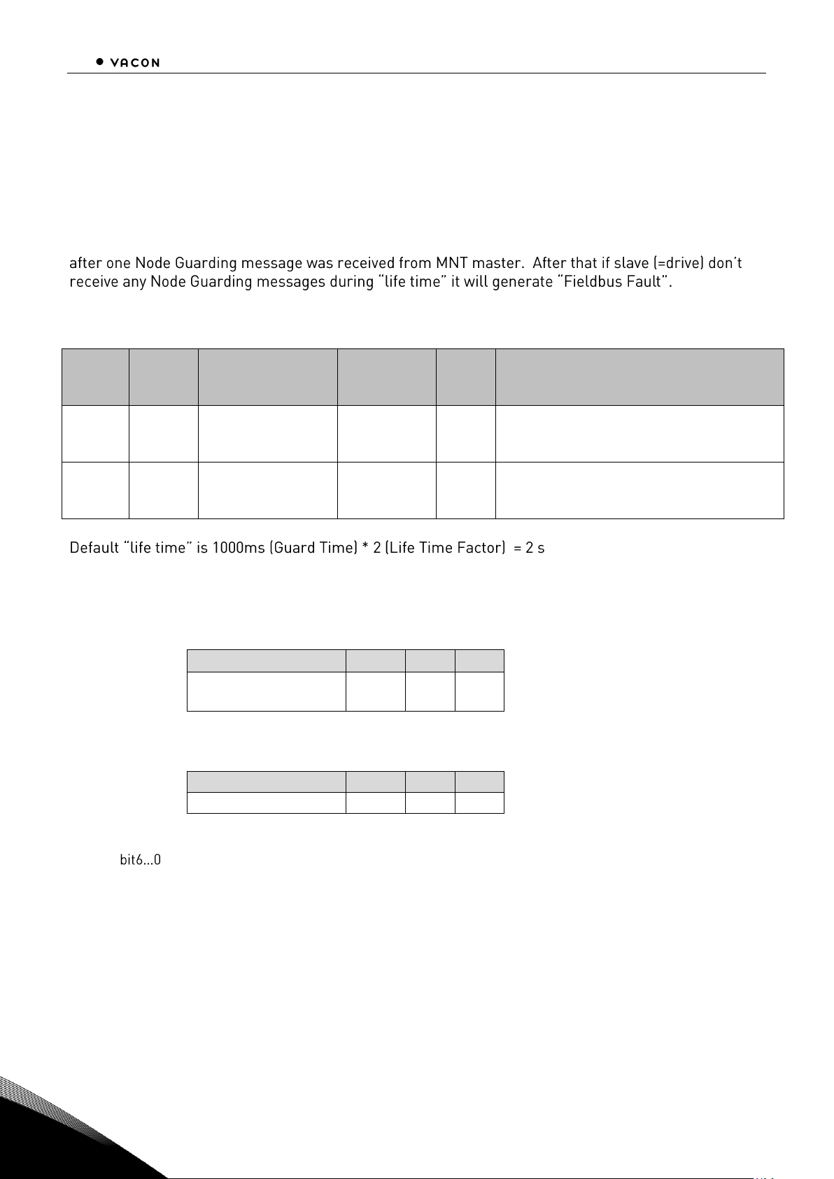
44 Node Guarding Protocol
Local contacts: http://drives.danfoss.com/danfoss-drives/local-contacts/
9
9. NODE GUARDING PROTOCOL This protocol is used to detect remote errors in the network. Master can update status of slaves and
slaves can guard is master active.
Each NMT slave uses one remote COB for node guarding protocol. The NMT Master polls each NMT
slaves at regular time interval. This time interval is called guard time and may be different for each
NMT slave. The response of the NMT slave contains the state of that NMT slave. Slave start guarding
VACON
®
CANopen option board has following items for guarding purposes:
Index
(HEX)
SubIndex
Name
Default
Min
Max
Type
Attr.
Descriptions
100C
00
Guard Time
1000
0
65535
u16
rw
This entry contains the guard time in
milli-seconds. It is 0, if not used.
Unit: ms
100D
00
Life Time Factor
2
0
255
u8
rw
The life time factor multiplied with the
guard time gives the life time for the
device. It is 0, if not used.
Example node guarding messages:
MASTER -> SLAVE (node id = 1)
Message
ID
Len
RTR
NMT (Node
Guarding)
0x701
0
1
SLAVE RESPONSE (node id = 1)
Message
ID
Len
1
NMT (Node Guarding)
0x701
1
X
X = bit7 0 / 1 (Toggle bit )
Slave state (e.g. 5 operational)
Page 47

Electronic Data Sheet, EDS-file 45
Local contacts: http://drives.danfoss.com/danfoss-drives/local-contacts/
10
10. ELECTRONIC DATA SHEET, EDS-FILE
The usage of devices in a communication network requires configuration of the device parameters
and communication facilities. CANopen defines a standardised way to access these parameters via
the object dictionary.
For handling of the complexity of CANopen systems Software Tools are required. This reduces the
complexity of the planning, configuration and analysis process and significantly increases the security
of the system.
For this purpose Software Tools need an electronic description of the CANopen devices. To allow the
usage of manufacturer independent Tools, this document defines a standardised file format called
Electronic Data Sheet EDS.
For the EDS-file for VACON
®
CANopen Option Board, go to http://drives.danfoss.com website.
Page 48
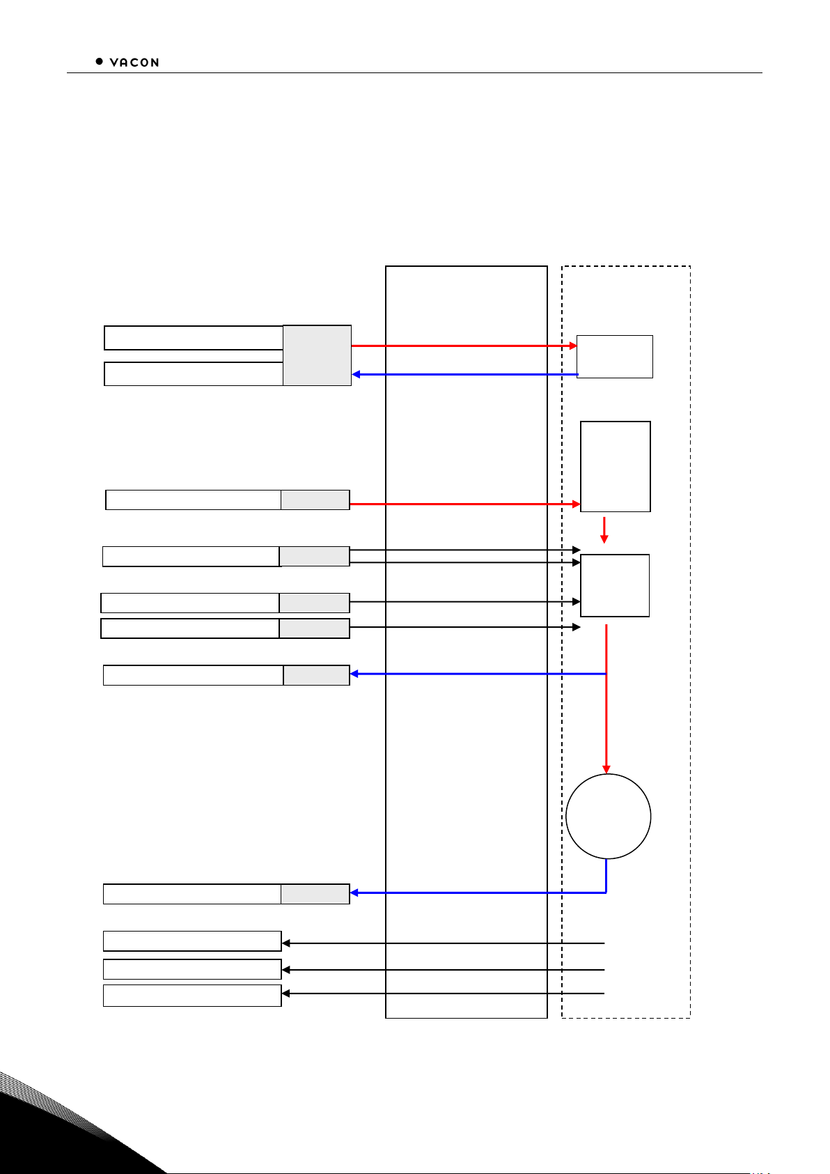
46 APPENDICES
Local contacts: http://drives.danfoss.com/danfoss-drives/local-contacts/
11
11. APPENDICES
appendix a - device profile for drives
VACON
®
CANopen option board follows the Drive device profile DSP-402. The Velocity mode is
supported.
Basic Device Control and Device Data Interface
vl_velocity_deceleration (6049h)
vl_velocity_acceleration (6048h)
vl_velocity_demand (6043h) RPM
vl_velocity_min_max_amount
%torque (2003h)
%current (2004h)
fault code (2063h)
vl_target_velocity (6042h) RPM
Drive Interface
Limit
Ramp
Motor
vl_control_effort (6044h) RPM
RPM to %
RPM to Hz
RPM to Hz
RPM to Hz
% to RPM
RPM to %
ActualSpeed
MinFrequency
MaxFrequency
DecelerationTime
AccelerationTime
FaultCode
controlword (6040h)
Application
RUN/STOP, FAULT
RUN/STOP,READY,FAUL
statusword (6041h)
State
Machine
MotorTorque
MotorCurrent
Page 49
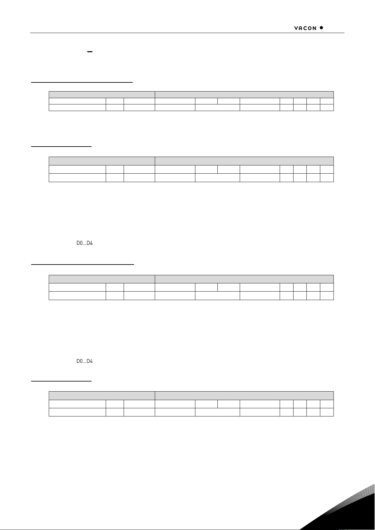
APPENDICES 47
Local contacts: http://drives.danfoss.com/danfoss-drives/local-contacts/
11
appendix b sdo messages
Read Dictionary Object: SDO1 Rx
Master to Slave (1)
Header
Data
ID
RTR
Len 1 2 3 4 5 6 7 8
0x601
0 4 Command
Object Index
Sub- Index
D0
D1
D2
D3
Command = 0x40
Command aaabbbbb (= 0100 0000)
aaa = 010, Initiate upload request
Response: SDO1 Tx
Slave (1) to Master
Header
Data
ID
RTR
Len 1 2 3 4
5 6 7
8
0x581
0
8
Reply
Object Index
Sub- Index
D0
D1
D2
D3
Reply = e.g. 0x43
Reply aaabcces (= 0100 0011)
aaa = 010 Initiate upload response
b = 0 not used
cc = 00 number of empty bytes ( that case answer consist of 4 bytes)
e = 1 expedited transfer
s = 1 data set size is indicated
Data
Write Dictionary Object: SDO1 Rx
Master to Slave (1)
Header
Data
ID
RTR
Len 1 2 3 4
5 6 7
8
0x601
0
8
Command
Object Index
Sub- Index
D0
D1
D2
D3
Command = e.g. 0x2B
Command aaabcces (= 0010 1011)
aaa = 010 Initiate download request
b = 0 not used
cc = 00 number of empty bytes ( that case answer consist of 4 bytes)
e = 1 expedited transfer
s = 1 data set size is indicated
Data
Response: SDO1 Tx
Slave (1) to Master
Header
Data
ID
RTR
Len 1 2 3 4
5 6 7
8
0x581
0
4
Reply
Object Index
Sub- Index
D0
D1
D2
D3
Reply = 0x60
Reply aaabbbbb (= 0110 0000)
aaa = 010 Initiate download response
bbbbb = 0 0000 not used
Page 50
48 APPENDICES
Local contacts: http://drives.danfoss.com/danfoss-drives/local-contacts/
11
appendix c process data contents
Process Data OUT (Slave Master)
The fieldbus master can read the actual values using process data variables.
Basic, Standard, Local/Remote, Multi-Step, PID control and Pump and fan control
applications use
process data as follows:
Data
Value
Unit
Scale
Process data OUT 1
Output Frequency
Hz
0,01 Hz
Process data OUT 2
Motor Speed
rpm
1 rpm
Process data OUT 3
Motor Current
A
0,1 A
Process data OUT 4
Motor Torque
%
0,1 %
Process data OUT 5
Motor Power
%
0,1 %
Process data OUT 6
Motor Voltage
V
0,1 V
The
Multipurpose
application has a selector parameter for every Process Data. The monitoring values
and drive parameters can be selected using the ID number (see VACON
®
NX All in One Application
Manual, Tables for monitoring values and parameters). Default selections are as in the table above.
Process Data IN (Master -> Slave)
ControlWord, Reference and Process Data are used with All-in One applications as follows:
Basic, Standard, Local/Remote, Multi-Step applications
Data
Value
Unit
Scale
Reference
Speed Reference
%
0.01%
ControlWord
Start/Stop
Command
Fault reset
Command
-
-
PD1 PD6
Not used
-
-
Page 51

APPENDICES 49
Local contacts: http://drives.danfoss.com/danfoss-drives/local-contacts/
11
Multipurpose control application
Data
Value
Unit
Scale
Reference
Speed Reference
%
0.01%
ControlWord
Start/Stop
Command
Fault reset
Command
-
-
Process Data IN1
Torque Reference
%
0.1%
Process Data IN2
Free Analog INPUT
%
0.01%
PD3 PD6
Not Used
-
-
PID control and Pump and fan control applications
Data
Value
Unit
Scale
Reference
Speed Reference
%
0.01%
ControlWord
Start/Stop
Command
Fault reset
Command
-
-
Process Data IN1
Reference for PID
controller
%
0.01%
Process Data IN2
Actual Value 1 to PID
controller
%
0.01%
Process Data IN3
Actual Value 2 to PID
controller
%
0.01%
PD4 PD6
Not Used
-
-
appendix d
Version 8 of the C6 Option board does not work the same way than the others. Some changes are
required at end of the PLC.
Page 52

www.danfoss.com
Vacon Ltd
Member of the Danfoss Group
Runsorintie 7
65380 Vaasa
Finland
Document ID:
DPD00896B
Rev. B
 Loading...