


vacon nx
®
ac drives
optaf
sto and atex option board
user manual


vacon • 1
TABLE OF CONTENTS
Document ID: DPD00891F
Revision release date: 21.10.2019
1. GENERAL ..............................................................................................................3
2. INSTALLATION OF THE OPTAF BOARD ...............................................................11
2.1 OPTAF board layout ......................................................................................................13
2.2 Control board VB00761 layout.......................................................................................13
3. STO AND SS1 SAFETY FUNCTIONS .....................................................................14
3.1 Safe Torque Off (STO) principle.....................................................................................15
3.2 Safe Stop 1 (SS1) principle ............................................................................................17
3.3 Technical details ...........................................................................................................19
3.3.1 Response times.................................................................................................................19
3.3.2 Input voltage levels ...........................................................................................................19
3.3.3 External dark test pulse filtering capability .....................................................................19
3.3.4 External light test pulse filtering capability .....................................................................20
3.3.5 Connections ......................................................................................................................20
3.3.6 Safety-related data according to the standard ................................................................21
3.4 Wiring examples ...........................................................................................................24
3.4.1 Example 1: OPTAF board without reset for Safe Torque Off (STO)..................................24
3.4.2 Example 2: OPTAF board with reset for Safe Torque Off (STO) or EN 60204-1 stop category 0
....................................................................................................................................................25
3.4.3 Example 3: OPTAF board with external safety relay module with or without reset for Safe
Torque Off (STO) or EN 60204-1 stop category 0 .......................................................................26
3.4.4 Example 4: OPTAF board with external time delayed safety relay for Safe Stop 1 (SS1) or EN
60204-1 stop category 1 .............................................................................................................27
3.5 Commissioning..............................................................................................................28
3.5.1 General wiring instructions ..............................................................................................28
3.5.2 Checklist for commissioning the OPTAF board ...............................................................30
3.5.3 Parametrizing the drive for the Safe Torque Off (STO) safety functions .........................31
3.5.4 OPTAF board parameter...................................................................................................32
3.5.5 Parametrizing the drive and the external time delayed safety relay for Safe Stop (SS1) safety
function .......................................................................................................................................32
3.5.6 Testing the Safe Torque Off (STO) or Safe Stop 1 (SS1) safety functions ........................33
3.5.7 Determining the drive STO level.......................................................................................33
3.6 Maintenance..................................................................................................................34
3.6.1 OPTAF-related monitoring values....................................................................................34
3.6.2 Faults related to the Safe Torque Off (STO) or Safe Stop 1 (SS1) safety functions .........34
4. THERMISTOR FUNCTION (ATEX).........................................................................37
4.1 Technical data ...............................................................................................................40
4.1.1 Functional description ......................................................................................................40
4.1.2 Hardware and connections...............................................................................................41
4.2 Commissioning..............................................................................................................43
4.2.1 General wiring instructions ..............................................................................................43
Local contacts: https://www.danfoss.com/en/contact-us/contacts-list/

vacon • 2
4.2.2 Parameter setting for ATEX function ...............................................................................43
4.2.3 Short circuit monitoring....................................................................................................44
4.2.4 Exceptional use of thermistor function on OPTAF board (similar to OPT-A3, not in compliance
with ATEX directive 94/9/EC) ......................................................................................................44
4.2.5 OPTAF board parameter...................................................................................................45
4.3 Maintenance..................................................................................................................46
4.3.1 Fault diagnosis of thermistor function .............................................................................46
NOTE! You can download the English and French product manuals with applicable safety,
warning and caution information from
http://drives.danfoss.com/knowledge-center/technical-documentation/.
REMARQUE Vous pouvez télécharger les versions anglaise et française des manuels produit
contenant l’ensemble des informations de sécurité, avertissements et mises en garde
applicables sur le site
http://drives.danfoss.com/knowledge-center/technical-documentation/
.
Local contacts: https://www.danfoss.com/en/contact-us/contacts-list/

GENERAL vacon • 3
1. GENERAL
This document covers OPTAF option board VB00328H (or newer) and VACON® NXP Control board
VB00761B (or newer).
Table 1. Version history of the manual
Date Revision Updates
• ATEX certificate added.
10/2012 B
1/2016 C
8/2017 D
8/2019 E
10/2019 F
• Figures updated throughout the manual.
• Other minor updates and layout changes throughout the manual.
• STO & SS1 standard info corrected
• EC type examination (STO & SS1) certificate
updated
• STO safety related data updated
• ATEX declaration of conformity added
• Other minor updates.Throughout the manual.
• Updated ATEX certificate
• Updated EC declaration
• Changed information related to IP54 requirement
in Chapters 1 and 2.
• Changed information related to programmable
relays in Figure 1 and Figure 17
• Removed notes related to edge sensitive start
command in chapters 3.4.1, 3.4.2, 3.4.3 and 3.4.4
• Other minor updates.Throughout the manual.
• Added figure on control board layout in chapter 2.2.
• Added new chapters 3.3.2, 3.3.3 and 3.3.4.
• Updated information on SIL3 in chapter 3.3.
• Updated wiring information in chapter 3.5.1.
• Updated chapter 3.5.6.
• Added fault subcodes 48-52 in 3.6 and 4.3.
• Created new chapter Maintenance, 4.3.
• Other minor updates.Throughout the manual.
• Added new content and image, chapters 3.1 and 4.
• Added data into a table, chapter 3.3.5.
• Added FR9-FR14 data into a table, chapter 3.3.6.
• Added data on fuses, chapter 3.5 and 4.2.
• Added fault reset information, chapter 3.5.4.
• Added new chapter for monitoring values, 3.6.1.
®
The OPTAF option board together with VACON
functions with VACON
®
NX family products.
NXP control board provides the following safety
Safe Torque Off (STO)
Hardware based ‘Safe Torque Off’ safety function to prevent the drive from generating torque
on the motor shaft. STO safety function has been designed for use in accordance with the
following standards:
• EN 61800-5-2 Safe Torque Off (STO) SIL3
• EN ISO 13849-1 PL “e” Category 3
• EN 62061 SILCL3
• IEC 61508 SIL3
• The function also corresponds to an uncontrolled stop in accordance with stop category 0,
EN 60204-1.
• EN 954-1, Category 3
Local contacts: https://www.danfoss.com/en/contact-us/contacts-list/

vacon • 4 GENERAL
The STO safety function has been certified by IFA*
NOTE! Adequate protection from environment must be guaranteed. An adequate protection
can be installation in an IP54 enclosure or the use of a drive with coated PCBs.
Safe Stop 1 (SS1)
SS1 safety function is realized in compliance with type C of the drives safety standard EN
61800-5-2 (Type C: “The PDS(SR) initiates the motor deceleration and initiates the STO
function after an application specific time delay”). SS1 safety function has been designed for
use in accordance with the following standards:
• EN 61800-5-2 Safe Stop 1 (SS1) SIL3
• EN ISO 13849-1 PL "e" Category 3
• EN 62061 SILCL3
• IEC 61508 SIL3
• The function also corresponds to a controlled stop in accordance with stop category 1, EN
60204-1.
The SS1 safety function has been certified by IFA *
NOTE! Adequate protection from environment must be guaranteed. An adequate protection
can be installation in an IP54 enclosure or the use of a drive with coated PCBs.
Motor Thermistor Over temperature protection (according to ATEX)
Overtemperature detection using thermistor. It can be used as a tripping device for ATEX certi-
fied motors.
The thermistor tripping function is certified by VTT** according to ATEX directive 94/9/EC.
All safety functions of the OPTAF board are described in this user's manual. The OPTAF option
board contains also two programmable output relays. (Note! Not part of any safety function.)
NOTE! The STO function is not the same as a prevention of unexpected start-up function. For fulfilling those requirements, additional external components are required according to appropriate
standards and application requirements. Required external components may be for example:
• Appropriate lockable switch
• A safety relay providing a reset function
NOTE! The safety functions of the OPTAF board do not comply with Emergency Switching Off according to EN 60204-1.
* IFA = Institut für Arbeitsschutz der Deutsche Gesetzlichen Unfallversicherung, Germany
** VTT = Technical Research Centre of Finland
Local contacts: https://www.danfoss.com/en/contact-us/contacts-list/

GENERAL vacon • 5
Date Issued by Date Approved by
15-04-2016 Signature
Name: Kimmo Syvänen
Title: Director, Premium Drives
15-04-2016 Signature
Name: Timo Kasi
Title: VP, Design Center Finland and Italy
Danfoss only vouches for the correctness of the English version of this declaration. In the event of the declaration being translated into any
other language, the translator concerned shall be liable for the correctness of the translation
ID No: DPD01854 Revision No: A Page
1of 1
Danfoss A/S
DK-6430 Nordborg
Denmark
CVR nr.: 20 16 57 15
Telephone: +45 7488 2222
Fax: +45 7449 0949
EU DECLARATION OF CONFORMITY
Danfoss A/S
Vacon Ltd
declares under our sole responsibility that the
Product name Vacon OPT-AF option board to be used with Vacon NXP control
board in NX family products
Product identification OPT-AF option board, VB00328H (or newer revision)
NXP control board, VB00761B (or newer revision)
Product Safety Functions Safe Torque Off, Safe Stop 1 (Specified in EN 61800-5-2:2007)
fulfils all of the relevant safety component requirements of EC Machinery Directive 2006/42/EC.
Notified body that carried out the EC type examination:
IFA – Institute for Occupational Safety and Health of the German Social Accident Insurance
Testing and Certification Body in BG-PRÜFZERT
Alte Heerstraße 111
D-53757 Sankt Augustin, Germany
European notified body, Identification number 0121 IFA Certificate No: IFA 1001221
The following standards and/or technical specifications referenced below were used:
- EN ISO 13849-1:2006
Safety of machinery – Safety-related parts of the control systems. Part 1: General principles for design
- EN ISO 13849-2:2006
Safety of machinery – Safety-related parts of the control systems. Part 2: Validation
- EN 60204-1:2006
Safety of machinery – Electrical equipment of machines – Part 1: General requirements
- EN 61800-5-2:2007
Adjustable speed electrical power drive systems – Part 5-2: Safety requirements – Functional
- IEC 61508:2000
Functional safety of electrical/electronic/programmable electronic safety-related systems – Parts 1-7
- EN 62061:2005
Safety of machinery – Functional safety of safety-related electrical, electronic and programmable
electronic control systems
Local contacts: https://www.danfoss.com/en/contact-us/contacts-list/
vacon • 6 GENERAL
Local contacts: https://www.danfoss.com/en/contact-us/contacts-list/
GENERAL vacon • 7
Local contacts: https://www.danfoss.com/en/contact-us/contacts-list/
vacon • 8 GENERAL
Local contacts: https://www.danfoss.com/en/contact-us/contacts-list/
GENERAL vacon • 9
Local contacts: https://www.danfoss.com/en/contact-us/contacts-list/
vacon • 10 GENERAL
Local contacts: https://www.danfoss.com/en/contact-us/contacts-list/
INSTALLATION OF THE OPTAF BOARD vacon • 11
!
N
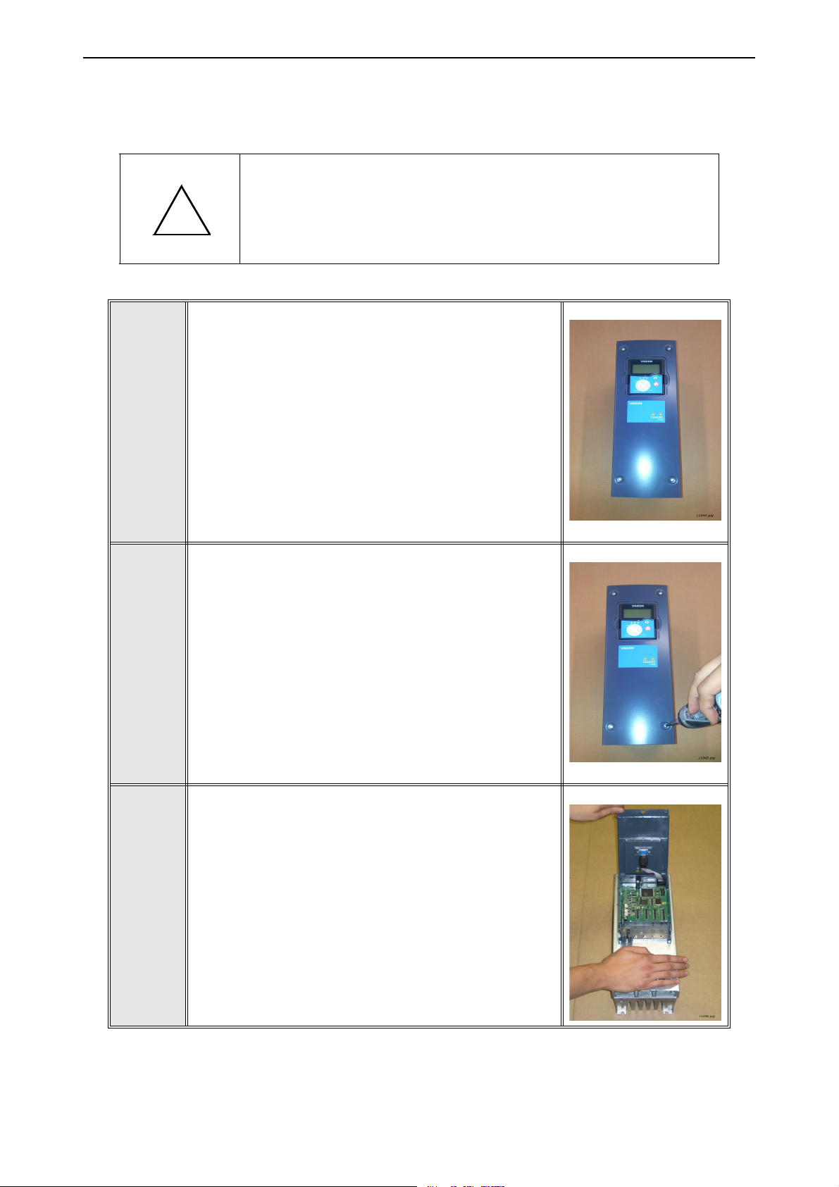
2. INSTALLATION OF THE OPTAF BOARD
A
B
OTE
VACON® NXP AC drive with IP54 enclosure.
Remove the main cover.
MAKE SURE THAT THE AC DRIVE IS SWITCHED OFF BEFORE AN
OPTION OR FIELDBUS BOARD IS CHANGED OR ADDED!
C
Open the cover of the control unit.
Local contacts: https://www.danfoss.com/en/contact-us/contacts-list/
vacon • 12 INSTALLATION OF THE OPTAF BOARD
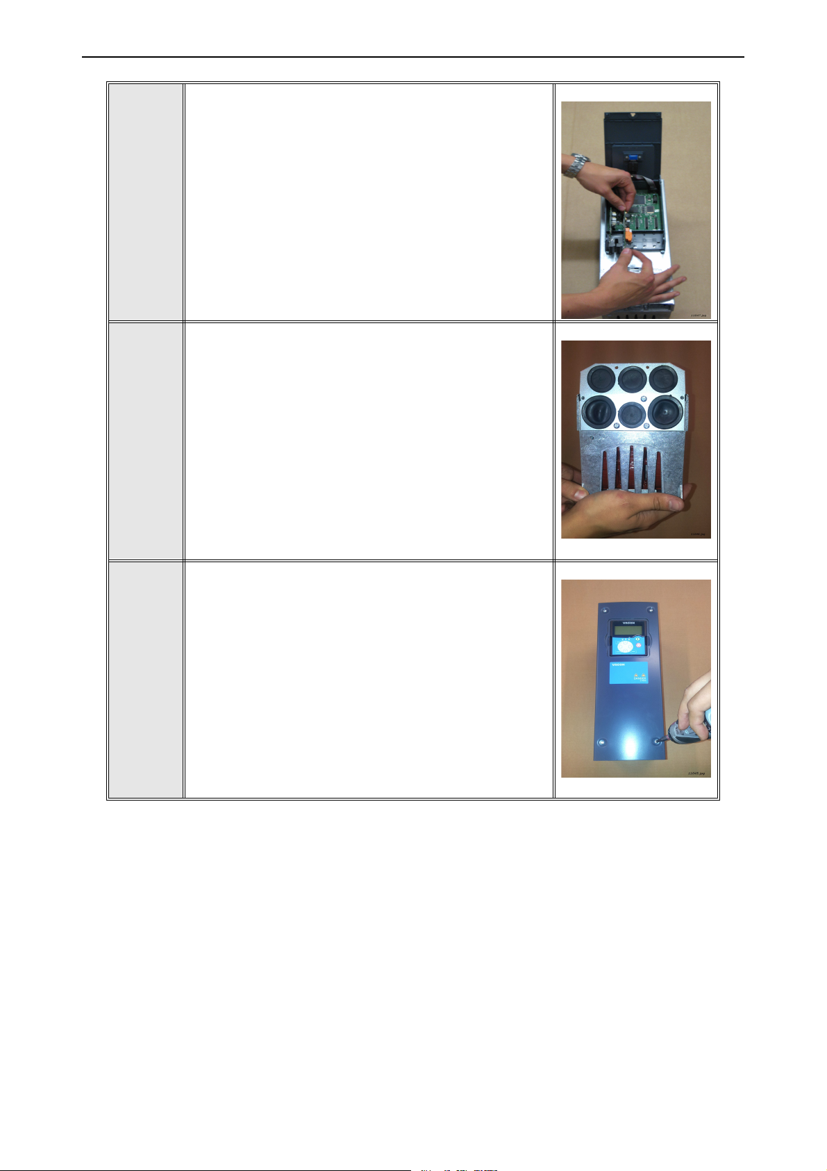
D
Install OPTAF option board in slot B on the control
board of the AC drive.
Make sure that the grounding plate fits tightly
in the clamp.
E
Cable installation:
STO and SS1 safety functions require the use
of cable sealing grommets or glands for all cables
in the drive. The grommets or glands must be
suitable for the type and amount of cables used
and they shall fulfill IP54 requirements.
F
See the User Manual for hole sizes for the Power
cables. The hole size is PG21 (28.3 mm) for the
control cables.
Close the cover of the control unit and attach the main
cover. Before attaching the main cover, check that the
gasket of the cover is not damaged for IP54 units. Use
a tightening torque of 0.9...1.1 Nm for the main cover
screws.
Local contacts: https://www.danfoss.com/en/contact-us/contacts-list/
INSTALLATION OF THE OPTAF BOARD vacon • 13
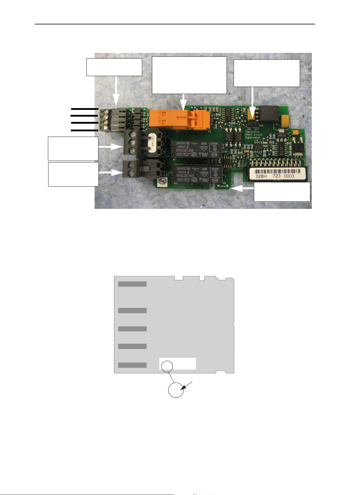
11052.emf
Jumper X10 for selecting
thermistor short
circuit supervision
+24V+
+24V+24V+
+24V-
SD1
SD2
Thermistor input
Thermistor Input: Thermistor
active > 4000 ohm. After being
active, the fault can be reset if
resistance is < 2000 ohm.
Jumper wire X12
See Chapter 4.2.4.
STO inputs two
independent channels
Programmable
Relay
"NO/NC"
Programmable
Relay
"NO"
761J19
2.1 OPTAF board layout
2.2 Control board VB00761 layout
The revision of the control board VB00761 can be determined from the sticker on the board.
Local contacts: https://www.danfoss.com/en/contact-us/contacts-list/
Figure 1. The layout of the OPTAF board
Ñ761JÌ3$ Í2AS{Ó
761J190400002AS
11966_00
Figure 2.The layout of the control board VB00761

vacon • 14 STO AND SS1 SAFETY FUNCTIONS
3. STO AND SS1 SAFETY FUNCTIONS
The safety functions of the OPTAF option board, such as the technical principle and data, wiring examples and commissioning, will be described in this chapter.
NOTE! Designing of safety-related systems requires special knowledge and
skills. Only qualified persons are permitted to install and set up the OPTAF
board.
The use of STO, SS1 or other safety functions does not itself ensure safety.
An overall risk evaluation is required in order to make sure that the commissioned system is safe. Safety devices like the OPTAF board must be correctly incorporated into the entire system. The entire system must be
designed in compliance with all relevant standards within the field of industry.
Standards such as EN 12100 Part 1, Part 2, & ISO 14121-1 provide methods
for designing safe machinery and for carrying out a risk assessment.
CAUTION! The information in this manual provides guidance on the use of
the safety functions that OPTAF option board provides together with
VACON
accepted practice and regulations at the time of writing. However, the end
product/system designer is responsible for ensuring that the system is safe
and in compliance with relevant regulations.
CAUTION! The OPTAF board and its safety functions do not electrically isolate the drive output from the mains supply. If electrical work is to be carried out on the drive, the motor or the motor cabling, the drive has to be
completely isolated from the mains supply e.g. using an external supply
disconnecting switch. See for e.g. EN 60204-1 section 5.3.
CAUTION! If STO or SS1 safety function is required in DriveSynch installation, please contact your nearest distributor for more information.
CAUTION! In LineSynch application the use of OPTAF board will not fulfill
STO or SS1 safety functions while the drive is in by-pass mode.
®
NXP control board. This information is in compliance with
Local contacts: https://www.danfoss.com/en/contact-us/contacts-list/

STO AND SS1 SAFETY FUNCTIONS vacon • 15
SD1+
+
SD1-
SD2+
SD2-
-
RO1/3
RO1/1
RO1/2
RO2/3
RO2/2
M
=
3~
NXP CONTROL UNIT
Control board
OPTAF board, slot B
POWER UNIT
Hardware
STO 1
PWM
control
Thermistor
Hardware
STO 2
Atex Safety
Function
Relays only for operational use,
not part of the safety functions
11053.eps
PWM
control
Control
logic
3.1 Safe Torque Off (STO) principle
The STO safety function of the OPTAF board allows the drive output to be disabled so that the drive
cannot generate torque in the motor shaft. For STO, the OPTAF board has two separate, galvanically
isolated inputs SD1
and SD2.
NOTE! Both SD1
and SD2 inputs are normally closed for the drive to be in enable state.
The STO safety function is achieved by disabling the drive modulation. The drive modulation is disabled through two independent paths controlled by SD1
and SD2 so that a single fault in any of the
safety related parts will not lead to the loss of the safety function. This is done by disabling the gate
driver signal outputs to the driver electronics. The gate drive output signals control the IGBT module. When gate drive output signals are disabled, the drive will not generate torque in the motor
shaft. See Figure 3.
In larger drives, the STO functionality extends to the power unit. See Figure 4.
If either of the STO inputs is not connected to a +24 V signal, the drive will not go to the RUN state.
Figure 3. STO safety function principle in VACON® NXP AC drive with the OPTAF board
Local contacts: https://www.danfoss.com/en/contact-us/contacts-list/

vacon • 16 STO AND SS1 SAFETY FUNCTIONS
NXP CONTROL UNIT
Thermistor
SD1+
SD1-
SD2+
SD2-
OPTAF board, slot B
+
-
RO1/3
RO1/1
RO1/2
RO2/3
RO2/2
Relays only for operational use,
not part of the safety functions
Atex Safety
Function
Control board
Control
logic
Hardware
STO 1
Hardware
STO 2
Enable
PWM control
POWER UNIT
Hardware
STO 2
Hardware
STO 1
Power
unit
logic
=
PWM control
3~
M
11970_uk.eps
Figure 4.STO safety function principle in VACON® NXP AC drive with the OPTAF board, FR9-FR14
Local contacts: https://www.danfoss.com/en/contact-us/contacts-list/

STO AND SS1 SAFETY FUNCTIONS vacon • 17
Time
0
Stop
Motor
deceleration
Frequency
f
actual
Time delay
Safe Torque Off (STO)
11054.emf
Safe Stop 1 (SS1)
Time Delayed Safety Relay Vacon NX Safe Torque Off (STO)
+
Subsystem
Safety Relay
Subsystem
STO
11055.emf
3.2 Safe Stop 1 (SS1) principle
The Safe Stop 1 (SS1) safety function initiates the motor deceleration and initiates the STO after a
(user set) time delay.
Figure 5. The principle of Safe Stop 1 (EN 61800-5-2, SS1 type c)
The Safe Stop 1 (SS1) safety function consists of two safety related subsystems, an external time
delayed safety relay and the STO safety function. These two subsystems combined compose the
Safe Stop 1 safety function as shown in Figure 6.
Figure 6. Safe Stop 1 (SS1) safety function
Local contacts: https://www.danfoss.com/en/contact-us/contacts-list/

vacon • 18 STO AND SS1 SAFETY FUNCTIONS
M
STO ch1
STO ch2
Digital input
OPT-AF
OPTAx
NXP control
Power Unit
Safety Relay
with timer
Switch
Time
Delay
OPTBx
Ramp stop
STO
11056.emf
Figure 7 shows the connection principle of Safe Stop 1 safety function.
- The time delayed safety relay outputs are connected to the STO inputs.
- A separate digital output from the safety relay is connected to a general digital input of the
VACON
®
NX drive. The general digital input must be programmed to detect the drive stop
command and initiates without time delay the drive stop function (must be set to "stop by
ramp") and causes motor deceleration.
Figure 7. The connection principle of Safe Stop 1 (SS1)
CAUTION! The system designer/user is responsible of understanding and
setting the time delay of the safety relay, due to the fact it is process/
machine dependent.
→ The time delay must be set to a greater value than the deceleration
time of the drive. The motor deceleration time is process/machine
dependent.
→ The stop function of the drive needs to be correctly set for the pro-
cess/machine.
See Chapter 3.5.5 concerning the parametrizing of Safe Stop 1 and Chapter 3.4.4 "Example 4" for
the wiring of Safe Stop 1.
Local contacts: https://www.danfoss.com/en/contact-us/contacts-list/

STO AND SS1 SAFETY FUNCTIONS vacon • 19
3.3 Technical details
3.3.1 Response times
Safety function Activation time De-activation time
Safe Torque Off < 20 ms 1000 ms
Safety Function Delay from stop signal at safety relay
input until activation of ramp stop
Safe Stop 1 (SS1) Safety relay delay + typ. 20 ms
(drive)
Time delay for Safe Torque Off (STO)
activation
System process dependent. User set-
table through the safety relay timer.
NOTE! Drive application software
dependent. Refer to the user manual
of the application in use.
3.3.2 Input voltage levels
Reversed polarity applied on STO input terminals does not cause disabling of STO function. The operation of OPTAF is not interfered by test pulses that are generated to the STO lines by the connected safety actuator as long as the test pulses fulfill certain requirements. See chapters 3.3.3 and
3.3.4 for details.
Table 2. Safe input data
Technical item or function Minimum Typical Maximum
Input Voltage (logic 1) 11 V 24 V 30 V
Input Voltage (logic 0) -3 V 0 V 3 V
Input Current (logic 1) 4 mA 10 mA 14 mA
Input Current (logic 0) -1 mA 1 mA
Input Resistance
2.5 k
Ω
Galvanic Isolation Yes
Short-circuit Protected Yes
Allowed discrepancy time of
5 s
physical inputs
3.3.3 External dark test pulse filtering capability
To recognize the short circuits from STO lines to power supplies or ground, some safety PLCs test
their outputs by pulsing the output from high to low level for short periods of time when STO is disabled. The pulses are known as 'dark test pulses'. To prevent these test pulses from causing false
fault indications, these dark test pulses are filtered out by STO inputs on OPTBJ. If the input voltagespecific values for dark test pulse durations are exceeded, the drive may indicate STO diagnostics
fault or STO may be activated. The used dark test pulse duration should always be shorter than the
specified minimum pulse withstanding duration. Limits for the test pulse duration, frequency and
period are given in Table 3. The filtering time is hardware-based and cannot be adjusted. External
dark test pulse filtering is included on VB00761 boards from revision J onwards. See Chapter 2.2
for identifying the board revision.
Local contacts: https://www.danfoss.com/en/contact-us/contacts-list/

vacon • 20 STO AND SS1 SAFETY FUNCTIONS
13006.emf
Table 3. Pulse characteristics
Pulse characteristics Dark test pulse Light test pulse
Test pulse length < 1 ms (24 V) < 1 ms (24 V)
Period > 20 ms > 20 ms
Frequency < 50 Hz < 50 Hz
3.3.4 External light test pulse filtering capability
To verify the switching capabilities of STO lines' switches, some safety actuators test their outputs
by pulsing the output from low to high level for short periods of time when STO is enabled. The pulses are known as 'light test pulses'. Allowed pulse characteristics are introduced in Table 3.
To prevent the test pulses from causing false STO deactivation commands or false fault indications,
the used connection must not create current path through STO inputs. Only connection example 1
is allowed. See the connection examples in Chapter 3.5.1. Only one switch is allowed to be tested at
a time.
CAUTION! When using other connection than "Connection example 1" with light
test pulse function, forbidden pulse structure or by testing both switches (SW P &
SW M) simultaneously, the drive may enter ready state even if STO should be activated. This may cause unintentional rotation of the motor shaft. See the connection examples in chapter 4.2.1.
3.3.5 Connections
In addition to the STO inputs, the board contains also a thermistor input. If the thermistor input is
not used it must be disabled. The thermistor input is disabled by making a short circuit to the terminals and setting the jumper X10 in "OFF" state. The thermistor input operation and instructions
are presented in Chapter 4.
I/O terminals on OPTAF
Table 4. OPTAF I/O terminals
Parameter reference
Terminal
on keypad and
Technical information
NCDrive
1 SD1
2 SD1
3 SD2
4 SD2
21
22
23
+
DigIN:B.2
Isolated STO input 1 +24 V
-Virtual GND 1
+
DigIN:B.3
Isolated STO input 2 +24 V
-Virtual GND 2
RO1/normal closed
RO1/common
RO1/normal open
DigOUT:B.1
Relay output 1 (NO/NC) *
Switching capacity 24 VDC/8 A
250 VAC/8 A
125 VDC/0.4 A
Min. switching load 5 V/10 mA
2526RO2/common
RO2/normal open
DigOUT:B.2
Relay output 2 (NO) *
Switching capacity 24 VDC/8 A
250 VAC/8 A
25 VDC/0.4 A
Min. switching load 5 V/10 mA
Local contacts: https://www.danfoss.com/en/contact-us/contacts-list/

STO AND SS1 SAFETY FUNCTIONS vacon • 21
Table 4. OPTAF I/O terminals
Parameter reference
Terminal
on keypad and
Technical information
NCDrive
2829TI1+
TI1-
DigIN:B.1
Thermistor input; R
max voltage = 10 V
> 4.0 kΩ (PTC)
trip
max current = 6.7 mA
* If 230 VAC is used as control voltage from the output relays, the control circuitry must be powered with
a separate isolation transformer to limit short circuit current and overvoltage spikes. This is to prevent
the welding on the relay contacts. Refer to standard EN 60204-1, section 7.2.9.
Table 5. STO function truth table
V
- V
SD1+
SD1-
0 VDC 0 VDC STO active
24 VDC 0 VDC
0 VDC 24 VDC
24 VDC 24 VDC STO inactive
V
SD2+
- V
SD2-
STO state
STO diagnostic fault and STO activation. Fault is activated after
inputs have been in different states for >5000 ms.
STO diagnostic fault and STO activation. Fault is activated after
inputs have been in different states for >5000 ms.
3.3.6 Safety-related data according to the standard
Safe Torque Off (STO) safety-related data
Control board VB00761
Standard
revision F and older
(all frame sizes)
EN 61800-5-2:2007 SIL 2
PFH = 2.98 x 10
Dual Channel Structure
EN 62061:2005 SIL CL 2
PFH = 2.98 x 10
Dual Channel Structure
EN/ISO 13849-1:2006 PL d
MTTF
d
DC
avg
PFH = 2.8 x 10
Category 3
IEC 61508:2000
High Demand Mode
SIL 2
PFH = 2.98 x 10
-9
-9
= 828 years
= low
-9
/hour
-9
/hour
/hour
/hour
Control board VB00761
revision G and newer
(FR4–FR8)
SIL 3
-9
PFH = 2.70 x 10
/hour
Dual Channel Structure
SIL CL 3
-9
PFH = 2.70 x 10
/hour
Dual Channel Structure
PL e
MTTF
DC
PFH = 2.70 x 10
= 1918 years
d
= low
avg
-9
/hour
Category 3
SIL 3
-9
PFH = 2.70 x 10
/hour
Control board VB00761
revision G
and newer with new
power units* (FR9–
FR14)
SIL 3
-9
PFH = 3.4 x 10
/hour
Dual Channel Structure
SIL CL 3
-9
PFH = 3.4 x 10
/hour
Dual Channel Structure
PL e
MTTF
DC
PFH = 3.4 x 10
= 1203 years
d
= low
avg
-9
/hour
Category 3
SIL 3
-9
PFH = 3.4 x 10
/hour
Dual Channel Structure
Local contacts: https://www.danfoss.com/en/contact-us/contacts-list/
Dual Channel Structure
Dual Channel Structure

vacon • 22 STO AND SS1 SAFETY FUNCTIONS
IEC 61508:2000
Low Demand Mode
* See Chapter 3.5.7.
SIL 2
PFD
= 2.61 x 10
avg
-4
TM = 20 years
Dual Channel Structure
SIL 3
PFD
T
= 2.30 x 10⁻⁴
avg
= 20 years
M
Dual Channel Structure
SIL 3
PFD
= 2.9 x 10
avg
-4
TM = 20 years
Dual Channel Structure
Safe Stop (SS1) safety-related data
The SS1 safety function consists of two subsystems with different safety-related data.
The subsystem consisting of the time delayed safety relay is manufactured by PHOENIX CONTACT
and of type:
- PSR-SCP-24DC/ESD/5X1/1X2/300 or
- PSR-SPP-24DC/ESD/5X1/1X2/300
See manufacturer user manual (by ID "2981428 or "2981431") for more information regarding the
time delayed safety relay.
PSR-SC/PP-24DC/ESD/5X1/1X2 300 safetyrelated data from user manual and certificate:
VACON® NX STO safety-related data:
IEC 61 508 SIL 2 EN 61800-5-2:2007 SIL 3
EN 62061 SIL CL 2 EN 62061:2005 SIL CL 3
DIN EN/ISO 13849-1
PFH
Subsystem
Safety Relay
PL d
Category 3
1.89 x 10⁻⁹ /hour
+
IEC 61508:2000 SIL 3
DIN EN/ISO 138491:2006
PFH
Subsystem
PL e
Category 3
2.70 x 10⁻⁹ /hour
NX STO
Safe Stop 1 (SS1) safety-related data:
EN 61800-5-2:2007 SIL 2
EN 62061:2005 SIL CL 3
→
IEC 61508:2000 SIL 2
DIN EN/ISO 13849-1:2006
PFH
PL d
Category 3
4.59 x 10⁻⁹ /hour
- For combining the two subsystems, the maximum safety integrity level or performance level
reached is the lowest of a subsystem.
→ SIL 2 or PL d
- The PFH value for a safety function of combined subsystems is the sum of all subsystems
PFH values.
PFH
SS1
= PFH
Safety Relay
+ PFH
= 1.89 x 10⁻⁹ /hour + 2.70 x 10⁻⁹ /hour = 4.59 x 10⁻⁹ /hour
NX STO
→ The result is within the requirements for SIL 2 or PL d (PFH is even within the requirements
for up to SIL 3/PL e).
Local contacts: https://www.danfoss.com/en/contact-us/contacts-list/

STO AND SS1 SAFETY FUNCTIONS vacon • 23
Abbreviations or safety parameters definitions
SIL Safety Integrity Level
PL Performance Level
PFH Probability of a dangerous random hardware Failure per Hour
Category Designated architecture for a safety function (from EN ISO 13849-1:2006)
PFD
T
M
AVG
The average probability of (random hardware) failure on demand
Mission time
Local contacts: https://www.danfoss.com/en/contact-us/contacts-list/

vacon • 24 STO AND SS1 SAFETY FUNCTIONS
F1
12345
6
L1 L2
MAIN CIRCUIT
L3
PE
PE
L1 L2 L3
UVW
PE
X10
2
7
PE
PE
PE
W1
M1
M
3
~
U11V1 W1
2
PE
R1
SPEED REFERENCE
S
CCW
CW
W12
1r 2p 2s1sh 2sh
OPTA1
Basic I/O
SLOT A
1
+10Vref
1
2
AIA1+
2
3
AIA1
3
X2
OPTAF
SLOTB
1
SD1+2SD1
S1
11
12
Safedisa ble
S6
START
13
14
4
AIA2+
4
5
AIA2
5
6
+24V
6
7
GND
7
3
SD2+4SD221RO1NC22RO1C
21
22
0V
+24V
CONTROL UNIT
S7
STOP
11
12
8
DIN1
8
9
DIN2
9
10
DIN3
10
11
CMA
11
X1
AB
23
RO1NO
CD
X2
25
RO2C
A BC D
26
RO2NO
X3
B
A
28
TI1+
12
+24V
12
13
GND
13
14
DIN4
14
15
DIN5
15
X10
X6
AB
29
TI1
C D
16
DIN6
16
17
CMB
17
18
AOA1+
18
19
AOA1
19
20
DOA1
20
START
reset
STOP
Vacon
+
select
enter
9
W10
2r1b 2b1r
OFF
Shortcircuitand
earthfa ult
protectedsupply
PE
PE
PE
PE
PE PE
11057.emf
3.4 Wiring examples
The examples in this chapter show the basic principles for wiring OPTAF board. Local norms and
regulations should be always followed in the final design.
3.4.1 Example 1: OPTAF board without reset for Safe Torque Off (STO)
Figure 8. Example 1.
Figure 8 shows a connection example of OPTAF board for Safe Torque Off safety function without
reset. The switch S1 is connected with 4 wires to the OPTAF board as shown above.
The power supply to S1 may come from OPT-A1 board (connector pins 6 & 7 in Figure 8) or it may
also be external.
When the switch S1 is activated (contacts open), the drive will go to STO state and motor (if running)
will stop by coasting. The drive will indicate: "A30 SafeTorqueOff".
When switch S1 is released (contacts closed), the drive returns to the ready state. The motor can
then be run with a valid start command.
Local contacts: https://www.danfoss.com/en/contact-us/contacts-list/

STO AND SS1 SAFETY FUNCTIONS vacon • 25
F1
12345
6
L1 L2
MAIN CIRCU IT
L3
L1 L2 L3
UVW
PE
X10
2
7
W1
M1
M
3
~
U11V1 W1
2
PE
R1
SPEED REFERENCE
S
CCW
CW
W12
1r 2p 2s1sh 2sh
OPTA1
Basic I/O
SLOT A
1
+10Vref
1
2
AIA1+
2
3
AIA1
3
X2
OPTAF
SLOT B
1
SD1+2SD1
S1
11
12
W10
2r1b 2b1r
S6
START
13
14
4
AIA2+
4
5
AIA2
5
6
+24V
6
7
GND
7
3
SD2+4SD221RO1NC22RO1C
21
22
CONTROL UNIT
S7
STOP
11
12
8
DIN1
8
9
DIN2
9
10
DIN3
10
11
CMA
11
X1
A B
23
RO1NO
C D
X2
25
RO2C
A B C D
26
RO2NO
X3
B
A
28
TI1+
12
+24V
12
13
GND
13
14
DIN4
14
15
DIN5
15
X10
X6
A B
29
TI1
C D
16
DIN6
16
17
CMB
17
18
AOA1+
18
19
AOA1
19
20
DOA1
20
START
reset
STOP
Vacon
+
select
enter
9
S8
RESET
13
14
OFF
Safe disable
Shortcircuit and
earth fault
protecteds upply
0V
+24V
PE
PE
PE
PE
PE
PE
PE PE
PE PE
PE
11058.emf
3.4.2 Example 2: OPTAF board with reset for Safe Torque Off (STO) or EN 60204-1 stop category 0
Figure 9. Example 2.
Figure 9 presents a connection example of OPTAF board for STO safety function with reset. The
switch S1 is connected with 4 wires to the OPTAF board as shown above. The digital input 3 (DIN3),
for example, is wired for the fault reset function. The reset function can be programmed to any of
the available digital inputs. The drive must be programmed to generate a fault in STO state.
The power supply to S1 may come from OPT-A1 board (connector pins 6 & 7 in Figure 8) or it may
also be external.
When the switch S1 is activated (contacts open), the drive will go to STO state and motor (if running)
will stop by coasting. The drive will indicate: "F30 SafeTorqueOff".
To start the motor operation again, following sequence is performed.
• Release switch S1 (contacts closed). The hardware is now enabled but the drive continues to
• Acknowledge the releasing of switch by edge sensitive reset function. The drive returns to
display the fault "F30 SafeTorqueOff".
the ready state.
• Giving a valid start command will start running the motor.
NOTE! For EN 60204-1 emergency stop according to stop category 0, use emergency stop button.
Local contacts: https://www.danfoss.com/en/contact-us/contacts-list/

vacon • 26 STO AND SS1 SAFETY FUNCTIONS
F1
12345
6
L1 L2
MAIN CIRCU IT
L3
L1 L2 L3
UVW
PE
X10
2
7
W1
M1
M
3
~
U11V1 W1
2
PE
R1
SPEED REFERENCE
S
CCW
CW
W12
1r 2p 2s1sh 2sh
OPTA1
Basic I/O
SLOT A
1
+10Vref
1
2
AIA1+
2
3
AIA1
3
X2
OPTAF
SLOT B
1
SD1+2SD1
S6
START
13
14
4
AIA2+
4
5
AIA2
5
6
+24V
6
7
GND
7
3
SD2+4SD221RO1 NC22RO1C
CONTROL UNIT
S7
STOP
11
12
8
DIN1
8
9
DIN2
9
10
DIN3
10
11
CMA
11
X1
A B
23
RO1NO
C D
X2
25
RO2C
AB C D
26
RO2NO
X3
B
A
28
TI1+
12
+24V
12
13
GND
13
14
DIN4
14
15
DIN5
15
X10
X6
AB
29
TI1
CD
16
DIN6
16
17
CMB
17
18
AOA1+
18
19
AOA1
19
20
DOA1
20
START
reset
STOP
Vacon
+
select
enter
9
131423
24
230Vac
L1
N
S1
1112
2122
Saf eDis able
A10
K3.1K1K1.2
K3.2K2K2.2
K1.1
K2.1
K3
S23
T22A1
A2
X2T11 T12
26
27
28
29
W1
1
2
OFF
DOLD BN5930.48/20 4230VAC
EXAMPLE:
+24V0V
31
33
S2
11
12
32
34
Alternative: Gate Switch*
Open
Shortcircuit and
earth fault
protected supply
Shortcircuitand
earth fault protected supply
For automatic reset
link X2 and T22
(Not allowed with Emergency stop)
PE
PE
PE
W3
2r1r
ON
PE
PE
PE
PE
PE
PE PE
PE
PE
S3
13
14
11059.emf
3.4.3 Example 3: OPTAF board with external safety relay module with or without reset for Safe Torque Off (STO) or EN 60204-1 stop category 0
Figure 10 presents a connection example of OPTAF board for STO safety function with external
safety relay module and without reset.
External safety relay module is connected to the switch S1. The used power supply to switch S1 is
230 VAC as an example. The safety relay module is connected to OPTAF board with 4 wires as shown
in Figure 10.
When the switch S1 is activated (contacts open), the drive will go to STO state and motor (if running)
Figure 10. Example 3.
will stop by coasting. The drive will indicate: "A30 SafeTorqueOff".
When switch S1 is released (contacts closed), the drive returns to the ready state. The motor can
then be run with a valid start command.
The external relay can be wired so that manual reset is required to reset the STO safety function.
More information regarding the safety relay module may be found from the safety relay documentation.
NOTE! For EN 60204-1 emergency stop according to stop category 0, use emergency stop button.
* Switch S1 in the figure can be replaced with the gate switch, then only Safe torque off mode is required. In
normal operation, both contacts are closed.
Local contacts: https://www.danfoss.com/en/contact-us/contacts-list/

STO AND SS1 SAFETY FUNCTIONS vacon • 27
F1
12345
6
L1 L2 L3
L1 L2 L3
UVW
PE
X10
W1
M1
M
3
~
U11V1 W1
2
PE
MAIN CIR CUIT
+04W12
1r 2 p 2s2sh1sh
R1
SPEED REFERENCE
S
CCW
CW
1 2
2
7
X2
OPTA1
Basic I/O
SLOT A
OPTAF
SLOT B
1
+10Vref2AIA1+
1
SD1+
3 4 5 6
3
AIA14AIA2+5AIA26+24V
2
SD13SD2+4SD221RO1NC
A10
57 67 A1
+
S12
RESET
S33
58
+24V
68
A2
0VDC
PHOENIX CONTACT
CONTROL UNIT
7
S6
START
13
14
8
S7
STOP
11
12
9 10
7
GND
X1
8
DIN1
A B C D
9
DIN2
X2
A B C
10
DIN3
D
22
RO1C
23
RO1NO25RO2C26RO2NO
S34
S1
11
12
S11 S22
21
22
11 12 13 14
X3
11
CMA
B
A
12
+24V
X6
A B C D
13
GND
14
DIN4
28
TI1+
X10
OFF
29
TI1
PSRSCP 24DC/ESD/5X 1/1X2/300 ( With s crew connection)
15 16 17 18
15
DIN516DIN617CMB18AOA1+
19 20
19
AOA120DOA1
START
reset
STOP
Vacon
+
select
enter
9
Shortcircuit and
earth fault
protected supply
0V
PE
PE
PE
W3
1r 2r
PE
PE
PE
PE PE
PE PE
PE
PE
S10 S21 S35
Bridgebetween S33/S35for automatic reset.
(Not all owed wit h emergency stop )
RAMP STOP
13
14232433344142
RS1 3E
4B R S1RS2 6B
3F R S2
24VDC
PSRSCP 24DC/ESD/5X1/1X2/300(With springcageconnection)
OR
11060.emf
3.4.4 Example 4: OPTAF board with external time delayed safety relay for Safe Stop 1 (SS1) or EN 60204-1 stop category 1
Figure 11. Example 4.
Figure 11 presents a connection example of OPTAF board for STO safety function with external time
delayed safety relay module for realizing the Safe Stop 1 or EN 60204-1 Stop Category 1.
External safety relay module is connected to the switch S1. The safety relay module is connected to
OPTAF board with 4 wires as shown in Figure 11. The time delay settings of the safety relay must
correspond to the application requirements.
When the switch S1 is activated, the safety relay module will immediately activate DIN6, which in
turn activates the STOP command to the drive. The STOP function is programmed to "Stop by
Ramp". The safety relay activates the Safe Torque Off state after the time delay has expired. The
time delay is set more than the deceleration time set in the drive to stop by ramp from maximum
speed. The drive will indicate: "A30 SafeTorqueOff".
When the switch S1 is released (contacts closed), the drive returns to ready state. The motor can
then be run with a valid start command.
The external relay can be wired so that manual reset is required to reset the STO safety function.
More information regarding the safety relay module may be found from the safety relay datasheet.
Local contacts: https://www.danfoss.com/en/contact-us/contacts-list/

vacon • 28 STO AND SS1 SAFETY FUNCTIONS
3.5 Commissioning
NOTE! The use of STO, SS1 or other safety functions does not itself ensure safety. Always make sure
that the safety of the entire system is confirmed. See also the warnings on page 14.
The OPTAF option board has an overvoltage protection that can activate due to fast transients when
connecting the +24 V. The activation causes the +24 V input to be short-circuited. It is essential to
protect the drive and the supply with a fuse placed on the supply line according to the instructions
in the drive operating guide. See, for example, VACON
Standalone Operating Guide. Do not use fuses with higher current rating. If the behavior reoccurs
after replacing the fuse, contact Danfoss for technical support.
3.5.1 General wiring instructions
• The wiring should be done according to the general wiring instructions for the specific product where OPTAF is installed. See wiring examples in the Figure 12, Figure 13 and Figure 14.
• If shielded cable is used, the shield must be connected to the drive's lid (PE) using a grounding clamp.
• EN 60204-1 part 13.5: The voltage drop from supply point to load must not exceed 5%.
• In practice, due to electromagnetic disturbances, the cable length should be limited to max.
200 m when using shielded cable and to max. 50 m when using unshielded cable. In a noisy
environment, the length of the cable could still be less in order to avoid unwanted tripping.
• Using unshielded cables is not allowed with some STO input configurations. Also some STO
input connection options are not allowed to be used with certain safety actuator types. See
Table 6 for details.
• The +24V power supply used for safety actuators may come from control board (e.g. drive's
control connector pins 6 & 7) or it may also be external, earth fault and short circuit protected power supply.
®
NXS/NXP Air-cooled Wall-mounted and
SAFETY ACTUATOR
+24V
SW P
OV
SW M
11967_uk
Figure 12. STO connection example 1
OPTAF
CHANNEL 1
SD1+
SD1-
OPTAF
CHANNEL 2
SD2+
SD2-
Local contacts: https://www.danfoss.com/en/contact-us/contacts-list/

STO AND SS1 SAFETY FUNCTIONS vacon • 29
SAFETY ACTUATOR
+24V
SW P
OV
SW M
+24V
11968_uk
Figure 13. STO connection example 2
SAFETY ACTUATOR
+24V
SW P
OPTAF
CHANNEL 1
SD1+
SD1-
OV
OPTAF
CHANNEL 2
SD2+
SD2-
OPTAF
CHANNEL 1
SD1+
Cable recommendation:
Type
+24V
SW P
11969_uk
OV
Figure 14. STO connection example 3
For example one of the following:
• 2x2x0.75mm2 (18 AWG) low voltage cable with two
individually shielded twisted pairs
• 2x2x0.75mm
2
(18 AWG) low voltage, unshielded,
twisted pair cable
• two separate 2x0.75mm
unshielded twisted pair cables.
SD1-
OPTAF
CHANNEL 2
SD2+
SD2-
2
(18 AWG) shielded or
See Table 6 for connections where shielded cable is required. In cases where the shield is marked
as being required, use the shield to separate the STO input channels from each other as shown in
Figure 15.
Local contacts: https://www.danfoss.com/en/contact-us/contacts-list/

vacon • 30 STO AND SS1 SAFETY FUNCTIONS
Individual pair Overall shield
Figure 15. Structure of cable with two individually shielded twisted pairs
Table 6. Recommended maximum cable lengths
Safety actuator type
Undiagnosed safety actuator
(i.e. emergency stop button or
relay contact)
Safety actuator with diagnosed
outputs (i.e. safety PLC)
(Optional)
Pair shield
Diagnostics on safety
actuator
No diagnostics
Outputs diagnosed using
e.g. dark test pulse,
light test pulse not used
Outputs diagnosed using
light test pulse
Cable jacket
11860_uk
Used STO input connection
Cable type
Shielded X 200 m 200 m
Unshielded X 30 m X
Shielded 200 m 200 m 200 m
Unshielded 30 m 30 m X
Shielded 200 m X X
Unshielded 30 m X X
STO
connection
example 1
STO
connection
example 2
STO
connection
example 3
X = Not recommended due to causes of electromagnetic disturbances, safety actuator configuration or behavior in failure
situations.
3.5.2 Checklist for commissioning the OPTAF board
The minimum steps required during connecting the Safe Torque Off (STO) or Safe Stop 1 (SS1) safety functions of the OPTAF board are shown in the checklist below. To comply with the functional
safety standards, each point of the checklist must be answered yes. For ATEX related issues see the
ATEX section.
Table 7. Checklist for commissioning the STO or SS1 safety functions.
Nr Step No Yes
Has a risk assessment of the system been carried out to ensure that
1
2
using the OPTAF board Safe Torque Off (STO) or Safe Stop 1 (SS1) safety
function is safe and according to local regulations?
Does the assessment include an examination of whether using external
devices such as a mechanical brake is required?
Local contacts: https://www.danfoss.com/en/contact-us/contacts-list/

STO AND SS1 SAFETY FUNCTIONS vacon • 31
Table 7. Checklist for commissioning the STO or SS1 safety functions.
Nr Step No Yes
Switch S1
- Has the switch S1 been chosen according to the required safety
performance target (SIL or PL) set during the risk evaluation?
- Is the switch S1 required to be lockable or otherwise secured in
3
4
5
6
7
8
9
10
Is the reset function edge sensitive?
If a reset function is used with Safe Torque Off (STO) or Safe Stop 1 (SS1) it
must be edge sensitive.
The shaft of a permanent magnet motor might in an IGBT fault situation
rotate up to 360 degrees / pole of the motor. Has it been ensured that the
system designed in such a way that the this can be accepted?
Have process requirements (including deceleration time) been considered for correct execution of Safe Stop 1 (SS1) safety function and are the
corresponding settings done according to Chapter 3.5.4?
Is the enclosure class or the cabinet class of the drive where the OPTAF
board is installed either:
Have the User's Manual instructions for the specific product, on EMC
compliant cabling been followed?
Has the system been designed in such a way that activating (enabling) the
drive through STO inputs will not lead to an unexpected start of the drive?
Have only approved units and parts been used?
the isolating position?
- Is it ensured that color coding and marking is in accordance with
the intended use?
- Is the external power supply earth fault and short circuit protected
(EN 60204-1)?
a) at least IP54?
b) coated PCBs are used in the drive?
11
12
13
14
Is the VACON® NXP control board VB00761 revision B or newer? (See the
®
sticker on the VACON
Is the VACON® NXP system software version NXP00002V179, or newer?
Has a routine been set up to ensure that the functionality of the safety
function is being checked at regular intervals?
Has this manual been read, understood and followed carefully?
NXP control board).
3.5.3 Parametrizing the drive for the Safe Torque Off (STO) safety functions
There are no parameters for the STO function itself.
In applications, there is a possibility to change the warning A30 "SafeTorqueOff" to a fault. For example in VACON
®
NXP Multi Purpose application through parameters protections SafeDis-
able mode, the STO state may be changed to generate a fault. As default, it is always set to generate
a warning.
NOTE! When STO state is changed to indicate a fault, the drive will display the fault "F30
SafeTorqueOff" even after the switch S1 have been released (contacts closed) and the hardware is
enabled. The fault must be acknowledged.
Local contacts: https://www.danfoss.com/en/contact-us/contacts-list/

vacon • 32 STO AND SS1 SAFETY FUNCTIONS
In application, there is also a possibility to indicate the STO state. This can be done through a digital
output.
®
For example the VACON
NXP multi purpose application provides the user with this possibility.
The indication of STO state could be parametrized to one of the relays on OPTAF board (B1 or B2).
The parameter for providing this feedback can be found in: parameters
signals
SafeDisableactiv.
output signals dig out
NOTE! The feedback or indication of the STO state is NOT part of the Safety functions.
3.5.4 OPTAF board parameter
Code Parameter Default Note
P7.2.1.2 Start-Up Prev “Fault” To start the motor operation after the STO safety func-
tion or a thermistor fault, an edge sensitive start command is required after the drive returns to ready state.
a) When OPTAF board parameter "Start-Up
Prev" is "Fault", the drive will generate a
"F26 Start-Up Prev" fault if start command is
on, when returning to ready state after the
STO safety function or a thermistor fault has
been active. The drive can be started with an
edge sensitive start command after fault
reset.
b) When OPTAF board parameter "Start-Up
Prev" is "Warning", the drive will generate a
"A26 Start-Up Prev" warning if start com-
mand is on, when returning to ready state
after the STO safety function or a thermistor
fault has been active. The drive can be started
with an edge sensitive start command. No
fault reset is required in this case.
c) When OPTAF board parameter "Start-Up
Prev" is "No action", the drive will not generate any indication. The drive will start with
any start command immediately after the
STO safety function or thermistor fault. No
fault reset is required in this case.
NOTE! In Fault mode, the drive fault reset should be delayed compared to a reset of the device controlling the STO inputs of OPTAF. Otherwise, OPTAF may re-detect the STO activation before the
STO is deactivated by the controlling device. This results in a need for second fault reset in the drive.
Other solution is to use Warning level. This behavior can occur, for example, with Advanced safety
options or with safety relays with reset signal where the used reset signal the same as the drive
fault reset.
3.5.5 Parametrizing the drive and the external time delayed safety relay for Safe Stop (SS1) safety function
Safe Stop 1 requires setting of time delay on the external safety relay component:
• Requirement: The time delay setting needs to be greater than the deceleration time set in
the drive
Local contacts: https://www.danfoss.com/en/contact-us/contacts-list/

STO AND SS1 SAFETY FUNCTIONS vacon • 33
NOTE! See manufacturer user manual for more information regarding the setting of the time delay.
Safe Stop 1 safety function requires that the drive is configured according to the following guidelines:
• Deceleration time must be set according to the machine or process requirement
• The drive stop function must be programmed to "stop by ramp"
• A dedicated digital stop input must be used (not combined with start command) for the drive
stop command
See the previous chapter for parametrizing the drive for Safe Torque Off (STO) safety function.
NOTE! The drive will indicate Safe Torque Off (STO) state when Safe Stop 1 time delay has expired
NOTE! If the time delay (of the external safety relay component) is NOT set correctly (time delay set
shorter than the required deceleration time of the process/machine), the motor will stop by coasting when the time delay expires.
3.5.6 Testing the Safe Torque Off (STO) or Safe Stop 1 (SS1) safety functions
NOTE! After connecting the board ALWAYS make sure that the STO or SS1 safety functions are
working properly by testing them before operating the system.
NOTE! Before testing the STO or SS1 safety functions, make sure that the checklist (Table 7) is inspected and completed.
NOTE! Concerning the SS1 safety function, make sure by testing that the drive's stop by ramp function is working in accordance with the process requirements.
When the STO safety function is activated, a code: A30 "SafeTorqueOff " appears on the control keypad display. This indicates that the STO safety function is active. After STO has been deactivated, the
warning remains active for 10 seconds.
3.5.7 Determining the drive STO level
Depending on the drive configuration, the STO implementation can be either SIL 2 or SIL 3. The
safety level can be seen on drive panel, see Table 8.
Table 8. Safety level
Code Monitor value Possible values
V7.2.2.2 Safety Levels SIL2 + PLd, SIL3 + PLe
Another way to determine the safety levels is the revision of the used PCBs. Small drives (up to FR8)
are dependent on the control board, VB00761, revision: the configuration is SIL 3 starting from revision G. See chapter 2.2 for details on determining the board revision.
Larger drives (FR9 and above) also depend on the power unit. For these configurations see the monitor value that is described above.
Local contacts: https://www.danfoss.com/en/contact-us/contacts-list/

vacon • 34 STO AND SS1 SAFETY FUNCTIONS
3.6 Maintenance
CAUTION! If any service or repair is to be conducted on the drive installed
with OPTAF board please follow the check list given in Chapter 3.5.2.
CAUTION! During maintenance breaks, or in case of service/repair, the OPTAF
board might have to be removed from its slot. After reconnecting the board,
ALWAYS make sure that the STO or SS1 safety functions are active and fully functional by testing them. See Chapter 3.5.6.
3.6.1 OPTAF-related monitoring values
Table below lists the OPTAF-specific values that should be considered for logging when submitting
support request for Danfoss support.
Table 9. Internal variables of the drive for monitoring and logging
Variable Source/Type Description
OPTAFStatus Firmware Shows internal status related to OPTAF option board.
B0
= Safe Off active
B1
= Thermistor input is active
B2
= Unexpected problem in Safe Off circuitry
B3
= Clear Off channel 1 active
B4
= Clear Off channel 2 active
B5
= Test pulse logic has detected short circuit in thermistor
input
B6
= Test pulse logic has detected problems in thermistor
input
B7
= OPTAF board overvoltage detected
B8
= OPTAF board undervoltage detected
B9
= Test pulse logic has detected problems in safe inputs
B10
= Trip input not set, even if Safe Off inputs are active
B11
= OPTAF board +5 V or REF voltage problem detected
B12
= OPTAF board has been removed
B13
= OPTAF board with EEPROM error detected
B14
= OPTAF board has been found by identification
B15
= Safe off fault generated, that may not be cleared
If there is room, also add other signals related to the logged situation to the monitoring. They can
help to link the OPTAF-specific signals to the drive state and external system events.
3.6.2 Faults related to the Safe Torque Off (STO) or Safe Stop 1 (SS1) safety functions
Table 10 shows the normal warning / alarm, generated when STO safety function is active.
Local contacts: https://www.danfoss.com/en/contact-us/contacts-list/

STO AND SS1 SAFETY FUNCTIONS vacon • 35
Table 10. Warning/alarm indicating that STO safety function is active
Fault code Warning Subcode Possible cause Correcting measures
30 SafeTorque-
Off
1 STO inputs SD1
activated through the OPTAF
& SD2 are
option board.
Table 11 shows faults that may be generated from the software part that monitors the hardware related to the STO safety function. If some of the faults listed below occur, the fault may NOT be reset.
Table 11. Single hardware problems detected in the STO safety function
Fault code Fault Subcode Possible cause Correcting measures
8System Fault30 STO inputs are in diffe-
rent state. This fault
occurs when the SD
inputs are in different
state more than 5 seconds.
8System Fault31 Thermistor short circuit
detected.
- Check the S1 switch.
- Check the cabling to
the OPTAF board
- Single hardware
problem possible in
either OPTAF board
or VACON® NXP
control board
.
- Correct the cabling
- Check the jumper for
the thermistor short
circuit supervision, if
thermistor function
is not used, and the
thermistor input is
short circuited.
8System Fault32 OPTAF board has been
removed.
- It is not allowed to
remove the OPTAF
board once it has
been recognized by
the software. NOTE!
There is only one
method to clear this
fault. By writing
"OPTAF Removed"
to "1" and then back
to "0" again. This
variable is found
from the "System
Menu" "Security"
(6.5.5).
8System Fault33 OPTAF board EEPROM
error (checksum, not
- Change the OPTAF
board.
answering…).
8System Fault34...36 OPTAF supply voltage
hardware problem
- Change the OPTAF
board.
detected.
Local contacts: https://www.danfoss.com/en/contact-us/contacts-list/

vacon • 36 STO AND SS1 SAFETY FUNCTIONS
Table 11. Single hardware problems detected in the STO safety function
Fault code Fault Subcode Possible cause Correcting measures
8System Fault37...40 Single hardware problem
detected in STO inputs.
8System Fault41...43 Single hardware problem
detected in the thermistor input.
8System Fault44...46 Single hardware problem
detected in STO inputs or
in the thermistor input.
8System Fault47 OPTAF board mounted in
old VACON® NXP control
board.
8System Fault48 Parameter Expander
boards/SlotB/Therm
Trip(HW) is set to OFF
even though the jumper
wire X12 is not cut.
8System Fault49 OPTAF is only compatible
with NXP.
8System Fault50 Hardware problem.
The fault only appears
with SIL3 compatible control boards.
- Change the OPTAF
board
VACON
trol board
or the
®
NXP con-
.
- Change the OPTAF
board.
- Change the OPTAF
board
VACON
trol board
- Change the VACON
or the
®
NXP con-
.
®
NXP control board to
VB00761.
- Correct the parameter according to the
jumper settings.
- Remove the OPTAF
board.
- Change the NXP
control board.
8System Fault51 Hardware problem. The
fault only appears with
SIL3 compatible configurations.
8System Fault52 Hardware problem. The
fault only appears with
SIL3 compatible control
boards.
- Contact your distributor.
- The power unit may
need to be replaced.
- Contact your distributor.
- Change the NXP
control board.
Local contacts: https://www.danfoss.com/en/contact-us/contacts-list/

THERMISTOR FUNCTION (ATEX) vacon • 37
(2)
11070.emf
4. THERMISTOR FUNCTION (ATEX)
The thermistor overtemperature supervision is designed in accordance with ATEX directive 94/9/
EC. It is approved by VTT Finland for group II (certificate nr. VTT 06 ATEX 048X), category (2) in the
G area (area in which potentially explosive gas, vapor, mist or air mixtures are present) and D area
(area with combustible dust). The "X" in the certificate number refers to special conditions for safe
use. See the conditions in the last note in this page.
II
0537
It can be used as an overtemperature tripping device for motors in explosive area (EX motors).
NOTE! The OPTAF board also contains the Safe Torque Off (STO) safety function. When STO is not
intended to be used, inputs SD1+(OPTAF: 1), SD2+(OPTAF:3) are to be connected to +24 V (e.g. OPTA1:6) & SD1-(OPTAF:2). SD2- (OPTAF:4) are to be connected to GND (for e.g. OPT-A1:7).
NOTE!
Safety devices like the OPTAF board must be correctly incorporated into the entire
system. The functionality of the OPTAF board is not necessarily suitable for all systems. The entire system must be designed in compliance with all relevant standards
within the field of industry. Maximum SIL capability of this function in the drive is
SIL1.
GD
CAUTION! The information in this manual provides guidance on the use of thermistor function for protecting overheating of motors in explosive atmosphere. This
information is ensured to be correct and in compliance with accepted practice and
regulations at the time of writing. However, the end product/system designer is
responsible for ensuring that the system is safe and in compliance with relevant
regulations.
CAUTION! During maintenance breaks, or in case of service/repair the OPTAF board
might have to be removed from its slot. After reconnecting the board ALWAYS make
sure that the thermistor function is working correctly by testing it.
CAUTION! The thermistor function on OPTAF board with VACON
®
NXP control is
used to protect the overheating of motors in explosive atmosphere. The drive itself
including OPTAF board can not be installed in explosive atmosphere.
NOTE! Special conditions required for safe use (X in the certificate number):
This function can be used with Exe-, Exd-, and ExnA- type of motors. In case of
Exe-, and ExnA- motors, the end user has to confirm that the installation of the
measurement circuit is done according to area classification. E.g. in Exe- and ExnAmotors PTC sensors shall be certified together with the motor according to the
requirements of the type of protection.
The allowed ambient temperature range for the drive is -10 ºC…+50 ºC.
Note: Changes in this chapter are only allowed with the permission of certification body.
Local contacts: https://www.danfoss.com/en/contact-us/contacts-list/

vacon • 38 THERMISTOR FUNCTION (ATEX)
Date Issued by Date Approved by
15-04-2016 Signature
Name: Kimmo Syvänen
Title: Director, Premium Drives
15-04-2016 Signature
Name: Timo Kasi
Title: VP, Design Center Finland and Italy
Danfoss only vouches for the correctness of the English version of this declaration. In the event of the declaration being translated into any
other language, the translator concerned shall be liable for the correctness of the translation
ID No:
DPD01853 Revision No: A Page 1of 1
Danfoss A/S
DK-6430 Nordborg
Denmark
CVR nr.: 20 16 57 15
Telephone: +45 7488 2222
Fax: +45 7449 0949
EU DECLARATION OF CONFORMITY
Danfoss A/S
Vacon Ltd
declares under our sole responsibility that the
Product name Vacon OPT-AF option board to be used with Vacon NXP control
board in NX family products
Product identification OPT-AF option board, VB00328H (or newer revision)
NXP control board, VB00761B (or newer revision)
Marking of the equipment
has been designed in conformity with the requirements of the Council directive for explosive atmospheres,
94/9/EC of March 1994 (until April 19th, 2016), 2014/34/EU (from April 20th, 2016) according to following
standards.
- EN ISO 13849-1 (2006)
Safety of machinery – safety-related parts of the control systems. Part 1: General principles for design
- EN ISO 13849-2 (2003)
Safety of machinery – safety-related parts of the control systems. Part 2: Validation
- EN 60079-14 (2007)
Electrical apparatus for explosive gas atmospheres.
Part 14: Electrical installations in hazardous area (other than mines).
- EN 61508-3(2010)
Functional safety of electrical/electronic/programmable electronic safety- related systems – Part3:
Software requirements
- EN ISO/IEC 80079-34 (2011)
Explosive atmospheres – Part 34: Application of quality systems for equipment manufacture.
- EN 50495 (2010)
Safety devices for ignition prevention.
VTT Industrial Systems, Electrical Ex apparatus, the Notified Body having identification number 0537, has
assessed the conformity of thermal motor protection system and has issued the certificate VTT 06 ATEX 048X.
It is ensured through internal measures and quality control that the product conforms at all times to the
requirements of the current Directive and the relevant standards.
Local contacts: https://www.danfoss.com/en/contact-us/contacts-list/

THERMISTOR FUNCTION (ATEX) vacon • 39
SD1+
+
SD1-
SD2+
SD2-
-
RO1/3
RO1/1
RO1/2
RO2/3
RO2/2
NXP CONTROL UNIT
Control board
OPTAF board, slot B
POWER UNIT
Thermistor
Atex Safety
Function
Relays only for operational use,
not part of the ATEX certified thermistor
function
M
=
3~
Hardware
STO 1
PWM
control
Hardware
STO 2
PWM
control
Control
logic
11068.eps
Figure 16. Thermistor function principle in VACON® NXP AC drive with the OPTAF board
Local contacts: https://www.danfoss.com/en/contact-us/contacts-list/

vacon • 40 THERMISTOR FUNCTION (ATEX)
11052.emf
+24V+
+24V+24V+
+24V-
SD1
SD2
Jumper wire X12
See Chapter 4.2.4.
Jumper X10 for selecting
thermistor short
circuit supervision
Thermistor input
Thermistor Input: Thermistor
active > 4000 ohm. After being
active, the fault can be reset if
resistance is < 2000 ohm.
STO inputs two
independent channels
Programmable
Relay
"NO/NC"
Programmable
Relay
"NO"
4.1 Technical data
4.1.1 Functional description
The thermistor supervision circuit of the OPTAF board is designed to provide a reliable way of disabling the drive modulation in case there is an overtemperature at the motor thermistor(s).
By disabling the drive modulation the feeding of the energy to the motor is prevented and a further
heating up of the motor due to this is avoided.
The thermistor supervision circuit meets the requirements in the ATEX directive by acting directly
on the "STO" safety function of the VACON
software and parameter independent way of preventing the energy supply to the motor.
Figure 17. The layout of the OPTAF board
®
NXP (See Figure 16) and is thus providing a reliable,
Local contacts: https://www.danfoss.com/en/contact-us/contacts-list/

THERMISTOR FUNCTION (ATEX) vacon • 41
4.1.2 Hardware and connections
Table 12. OPTAF I/O terminals
Parameter reference
Terminal
on keypad and
Technical information
NCDrive
1SD1
2SD1
3SD2
4SD2
21
22
23
+
-Virtual GND 1
+
-Virtual GND 2
RO1/normal closed
RO1/common
RO1/normal open
DigIN:B.2
DigIN:B.3
DigOUT:B.1
Isolated STO input 1 +24 V
Isolated STO input 2 +24 V
Relay output 1 (NO/NC) *
Switching capacity 24 VDC/8 A
250 VAC/8 A
125 VDC/0.4 A
Min. switching load 5 V/10 mA
2526RO2/common
RO2/normal open
DigOUT:B.2
Relay output 2 (NO) *
Switching capacity 24 VDC/8 A
250 VAC/8 A
125 VDC/0.4 A
Min. switching load 5 V/10 mA
2829TI1+
TI1-
DigIN:B.1
Thermistor input; R
max voltage = 10 V
> 4.0 kΩ (PTC)
trip
max current = 6.7 mA
The thermistor (PTC) is connected between the terminals 28(TI1+) and 29(TI1-) of the OPTAF board.
The optocoupler isolates the thermistor inputs from the control board potential.
* If 230 VAC is used as control voltage from the output relays, the control circuitry must be powered with a separate isolation transformer to limit short circuit current and overvoltage spikes. This is to prevent the welding
on the relay contacts. Refer to standard EN 60204-1, section 7.2.9.
The overtemperature is detected by hardware on OPTAF board. See temperature versus resistance
curve as in the figure below.
Local contacts: https://www.danfoss.com/en/contact-us/contacts-list/

vacon • 42 THERMISTOR FUNCTION (ATEX)
11069.emf
Figure 18. Typical characteristics of a motor-protection sensor as specified
in DIN 44081/DIN 440
Local contacts: https://www.danfoss.com/en/contact-us/contacts-list/

THERMISTOR FUNCTION (ATEX) vacon • 43
4.2 Commissioning
NOTE! Installation, testing and service work on the OPTAF board can be performed only by professional persons.
NOTE! It is not allowed to perform any repair work on the OPTAF board.
The OPTAF option board has an overvoltage protection that can activate due to fast transients when
connecting the +24 V. The activation causes the +24 V input to be short-circuited. It is essential to
protect the drive and the supply with a fuse placed on the supply line according to the instructions
in the drive operating guide. See, for example, VACON
Standalone Operating Guide. Do not use fuses with higher current rating. If the behavior reoccurs
after replacing the fuse, contact Danfoss for technical support.
4.2.1 General wiring instructions
The thermistor connection must be done using a separate control cable. It is not allowed to use
wires belonging the motor supply cables or any other main circuit cables. It is recommended to use
a shielded control cable.
®
NXS/NXP Air-cooled Wall-mounted and
Maximum cable length without
short circuit monitoring
X10: OFF
Maximum cable length with
short circuit monitoring
X10: ON
>= 1.5 sq mm 1500 meters 250 meters
NOTE! It is recommended to test the ATEX functionality using thermistor input on OPTAF board periodically (typically once a year). For testing, the thermistor connection to the OPTAF board is disconnected. The drive ready signal goes low (green LED on the keypad goes OFF). Check for the
corresponding warning or fault indication in the drive according to the parameter setting explained
in Chapter 4.2.2.
4.2.2 Parameter setting for ATEX function
In case of overtemperature, the drive modulation is disabled. The drive will not anymore feed energy to the motor thus preventing further overheating of the motor. See Figure 16.
When drive is connected to the main power and if the motor temperature is below overtemperature
limits (see Figure 18), the drive goes to ready state. The motor may start in presence of start command from a selected control place.
If the motor temperature is above the overtemperature limits (see Figure 18), fault /warning (F29)
thermistor is activated depending on the programming in the application.
The application programming for the thermistor fault is as follows e.g. in factory applications.
Code Parameter Default ID Note
P2.7.21 Response to
Thermistor Fault
2 732 0= No Response
1= Warning
2= Fault according to Stop Mode. *
3= Fault, stop by coasting.
* With OPTAF board according to ATEX directive 94/9/EC (i.e jumper wire X12 not cut) , response
to thermistor fault = 2 is always same as response to thermistor fault =3, i.e. stop by coasting.
When the resistance of the thermistor(s) mounted in the motor goes above 4 kΩ due to motor overheating, the drive modulation is disabled within 20 ms. Fault F29 or warning A29 is generated in the
drive according to the above-mentioned programming.
Local contacts: https://www.danfoss.com/en/contact-us/contacts-list/

vacon • 44 THERMISTOR FUNCTION (ATEX)
According to the curve, when the temperature falls below 2 kΩ (see Figure 18), the thermistor function allows the drive to be enabled again.
The thermistor fault configuration cause following reactions:
• Response to thermistor fault = No action. No warning/ fault is generated in case of overtemperature. The drive goes to run disable mode. The drive can be restarted when temperature
is normalized, by giving a valid start command.
• Response to thermistor fault = Warning. A29 is generated in case of overtemperature. The
drive goes to run disable mode. The drive can be restarted when temperature is normalized
by giving a valid start command when the drive has returned to Ready state.
• Response to thermistor fault = Fault. F29 is generated in case of overtemperature and the
drive goes to run disable mode. When the temperature is normalized, a reset command is
needed before the drive can be restarted. The drive returns to Ready state. The valid start
command is then needed to restart the drive.
NOTE! With OPTAF board according to ATEX directive 94/9/EC (i.e jumper wire X12 not cut) all
VACON
®
NXP drives are programmed to accept only an edge sensitive start command for a valid
start after a thermistor fault. To start the motor operation, a new start command is required after
the drive returns to ready state.
4.2.3 Short circuit monitoring
The thermistor inputs TI1+ and TI1- are monitored for short circuit. If a short circuit is detected, the
drive modulation is disabled within 20ms, F8 system fault (subcode 31) is generated. When the short
circuit has been removed, the drive can be reset only after power recycle to the VACON
®
NXP con-
trol board.
The short circuit monitoring can be enabled or disabled using the jumper X10 in ON or OFF position
respectively. The jumper is set in ON position by factory default.
Important: For the functionality of OPTAF board according to ATEX directive 94/9/EC, it
must be checked that the jumper wire X12 is not damaged or cut. Also set the parameter Expander Boards/Slot B/ "Therm Trip (HW)" to "ON" (P.7.2.1.1).
4.2.4 Exceptional use of thermistor function on OPTAF board (similar to OPT-A3, not in compliance with ATEX directive 94/9/EC)
In systems where the drive detects the overtemperature of the motor through a thermistor input,
there might be a need of running down the whole system in a controlled way or continue running
the motor. In these cases the thermistor input must not cause an immediate stop of the drive. To
achieve this functionality, the following actions must be carried out:
• Cut the jumper wire X12 on OPTAF board.
• Set the jumper X10 to OFF position (short circuit monitoring disabled).
• Set the parameter Expander Boards/Slot B/ “Therm Trip (HW)” to “Off”.
WARNING: When the jumper wire X12 is cut, the OPTAF board is not
more valid for using in an environment that requires a certified overheating protection device according to the ATEX directive 94/9/EC.
Local contacts: https://www.danfoss.com/en/contact-us/contacts-list/

THERMISTOR FUNCTION (ATEX) vacon • 45
4.2.5 OPTAF board parameter
Code Parameter Default Note
P7.2.1.1 Therm Trip
(HW)
“On” Correct settings:
• "Jumper wire X12 not cut and this board parameter "On" (for ATEX)
Refer 4.2.4
• "Jumper wire X12 cut and this board parameter
"Off" (for no ATEX and similar to OPT-A3)
Wrong settings:
• "If jumper wire X12 is cut and this board parameter
is "On", thermistor trip will cause unresettable
System Fault 8, subcode 41.
• "If jumper wire X12 is not cut and this board
parameter is "Off", thermistor trip will cause unresettable System Fault 8, subcode 48.
P7.2.1.2 Start-Up Prev “Fault” To start the motor operation after the STO safety function
or a thermistor fault, an edge sensitive start command is
required after the drive returns to ready state.
a) When OPTAF board parameter "Start-Up Prev"
is "Fault", the drive will generate a "F26 StartUp Prev" fault if start command is on, when
returning to ready state after the STO safety
function or a thermistor fault has been active.
The drive can be started with an edge sensitive
start command after fault reset.
b) When OPTAF board parameter "Start-Up Prev"
is "Warning", the drive will generate a "A26
Start-Up Prev" warning if start command is on,
when returning to ready state after the STO
safety function or a thermistor fault has been
active. The drive can be started with an edge
sensitive start command. No fault reset is
required in this case.
c) When OPTAF board parameter "Start-Up Prev"
is "No action", the drive will not generate any
indication. The drive will start with any start
command immediately after the STO safety
function or thermistor fault. No fault reset is
required in this case.
Local contacts: https://www.danfoss.com/en/contact-us/contacts-list/

vacon • 46 THERMISTOR FUNCTION (ATEX)
4.3 Maintenance
4.3.1 Fault diagnosis of thermistor function
The table below shows the normal fault / warning, generated when thermistor input is active.
Table 13. Fault/ Warning indicating that the thermistor is active.
Fault
code
29 Thermistor 1 Thermistor input is acti-
Fault/Warning Subcode Possible cause Correcting measures
The resistance of thermis-
vated (> 4 k
Ω) on the OPTAF
option board.
tor input must go below 2
Ω to be able to restart the
k
drive.
The table below shows faults that may be generated from the software part that monitors the hardware related to the STO and thermistor function. If some of the faults mentioned in this table occur,
the fault may NOT be reset.
Table 14. Faults related to the STO & thermistor function
Fault
code
8System Fault30 STO inputs are in different
8System Fault31 Thermistor short circuit
Fault Subcode Possible cause Correcting measures
- Check the S1 switch.
state. This fault occurs
when the STO inputs are in
different state more than 5
seconds.
- Check the cabling to the
OPTAF board.
- Single hardware problem
possible in either OPTAF
board
control board.
or VACON® NXP
- Correct the cabling.
detected.
- Check the jumper for the
thermistor short circuit
supervision, if thermistor
function is not used, and the
thermistor input is short
circuited.
8System Fault32 OPTAF board has been
removed.
8System Fault33 OPTAF board EEPROM
error (checksum, not
answering…).
8System Fault34…36 OPTAF supply voltage hard-
ware problem detected.
Local contacts: https://www.danfoss.com/en/contact-us/contacts-list/
- It is not allowed to remove
the OPTAF board once it has
been recognized by the
software. NOTE! There is
only one method to clear
this fault. By writing
"OPTAF Removed" to "1"
and then back to "0" again.
This variable is found from
the "System Menu" "Security" (6.5.5).
- Change the OPTAF board.
- Change the OPTAF board.

THERMISTOR FUNCTION (ATEX) vacon • 47
Table 14. Faults related to the STO & thermistor function
Fault
code
Fault Subcode Possible cause Correcting measures
8System Fault37…40 Single hardware problem
detected in STO inputs.
8System Fault41…43 Single hardware problem
detected in the thermistor
input.
8System Fault44…46 Single hardware problem
detected in STO inputs or in
the thermistor input.
8System Fault47 OPTAF board mounted in
®
old VACON
NXP control
board.
8System Fault48 Parameter Expander
boards/SlotB/Therm
Trip(HW) is set to OFF even
though the jumper wire X12
is not cut.
8System Fault49 OPTAF is only compatible
with NXP.
- Change the OPTAF board
or the VACON® NXP control board
.
- Change the OPTAF board.
- Change the OPTAF board
or the VACON® NXP control board.
- Change the VACON
®
NXP
control board to VB00561,
rev. H or newer.
- Correct the parameter
according to the jumper
settings.
- Remove the OPTAF board.
8System Fault50 Hardware problem.
The fault only appears with
SIL3 compatible control
boards.
8System Fault51 Hardware problem. The
fault only appears with SIL3
compatible configurations.
8System Fault52 Hardware problem. The
fault only appears with SIL3
compatible control boards.
- Change the NXP control
board.
- Contact your distributor.
- The power unit may
need to be replaced.
- Contact your distributor.
- Change the NXP control board.
Local contacts: https://www.danfoss.com/en/contact-us/contacts-list/

www.danfoss.com
Vacon Ltd
Member of the Danfoss Group
Runsorintie 7
65380 Vaasa
Finland
Document ID:
DPD00891F
Rev. F
Sales code: DOC-OPTAF-10+DLUK
 Loading...