

Page 1

vacon® nx
ac drives
liquid-cooled drives
heat exchanger
application manual
Page 2

Page 3

vacon • 1
INDEX
Document code: DPD01890A
Date edited: 5.8.2016
1. General .............................................................................................................................. 2
2. Control I/O ......................................................................................................................... 3
3. Parameter lists .................................................................................................................. 4
3.1 Monitoring values (Control keypad: menu M1) .......................................................................... 4
3.2 Basic parameters (Control keypad: Menu M2 G2.1) ............................................................. 8
3.3 Input signals (Control keypad: Menu M2 G2.2) ..................................................................... 9
3.4 Output signals (Control keypad: Menu M2 G2.3) ................................................................. 10
3.5 Drive control parameters (Control keypad: Menu M2 G2.4) ............................................... 14
3.6 Prohibit frequency parameters (Control keypad: Menu M2 G2.5) ...................................... 14
3.7 Motor control parameters (Control keypad: Menu M2 G2.6) .............................................. 15
3.8 Protections (Control keypad: Menu M2 G2.7)...................................................................... 16
3.9 Autorestart parameters (Control keypad: Menu M2 G2.8) ................................................. 17
3.10 PID control parameters (Control keypad: Menu M2 G2.9).................................................. 17
3.11 Flow control parameters (Control keypad: Menu M2 G2.10).............................................. 18
3.12 Fieldbus parameters (Control Keypad: Menu M2 G2.11) ..................................................... 19
3.13
Keypad control (Control keypad: Menu M3) ............................................................................. 20
3.14 System menu (Control keypad: M6) ......................................................................................... 20
3.15 Expander boards (Control keypad: Menu M7) ......................................................................... 20
4. Description of parameters ............................................................................................... 21
4.1 Keypad control parameters ...................................................................................................... 52
24-hour support: +358 (0)201 212 575 • Email: vacon@vacon.com
Page 4

2 • vacon General
heat exchanger application
1. GENERAL
This application is aimed to be used in the Vacon liquid-cooled AC drive inside the Heat exchanger
unit.
The idea with the application is to maintain a constant flow of coolant through the heat exchanger
and through the Vacon liquid-cooled drive.
The user sets a certain speed for the pump of the heat exchanger unit that produces a sufficient flow
through the Vacon liquid-cooled drives to keep them cooled. This speed is NOT regulated but fixed
by a parameter set value.
The Vacon AC drive also handles the temperature of the water in the heat exchanger unit by
regulating the valve that handles the coolant intake to the heat exchanger element (from the
customer's system). This regulation is based on the temperature of the water in the pipes between
the outlet of the heat exchanger pump and the inlet of the cooling element of the Vacon liquid-cooled
drive.
The actual value of the temperature for the regulation comes from a sensor called FSA11. This is a
type of flow switch that measures both the temperature of the coolant and the flow in the pipes. If
there is not enough flow in the pipe the sensor gives a signal that tells the drive to stop due to
insufficient flow.
Vacon NX AC drives can be connected to the Profibus DP using a fieldbus board. The AC drive can
then be controlled, monitored and programmed from the Host system. Profibus fieldbus board
(OPT-C5) is normally included in the delivery of Vacon NX liquid-cooled drive Heat Exchanger
Solution. The Profibus fieldbus board must be installed in slot E on the control board of the AC drive.
For more information on the Profibus fieldbus board, see Vacon OPTC3/C5 Profibus Option Board
User Manual.
The standard delivery also includes I/O boards OPT-A1 (placed in slot A), OPT-A2 (placed in slot B)
and OPT-B5 (placed in slot C or D). The application, however, offers you more signals than the
standard set of I/O boards allows you to connect. If you wish to use one additional analogue input
signal and/or two additional analogue output signals, we recommend you to order Vacon I/O board
OPT-B4 and place it in the last free board slot (C or D).
1
Tel. +358 (0)201 2121 • Fax: +358 (0)201 2121 205
Page 5
Control I/O vacon • 3
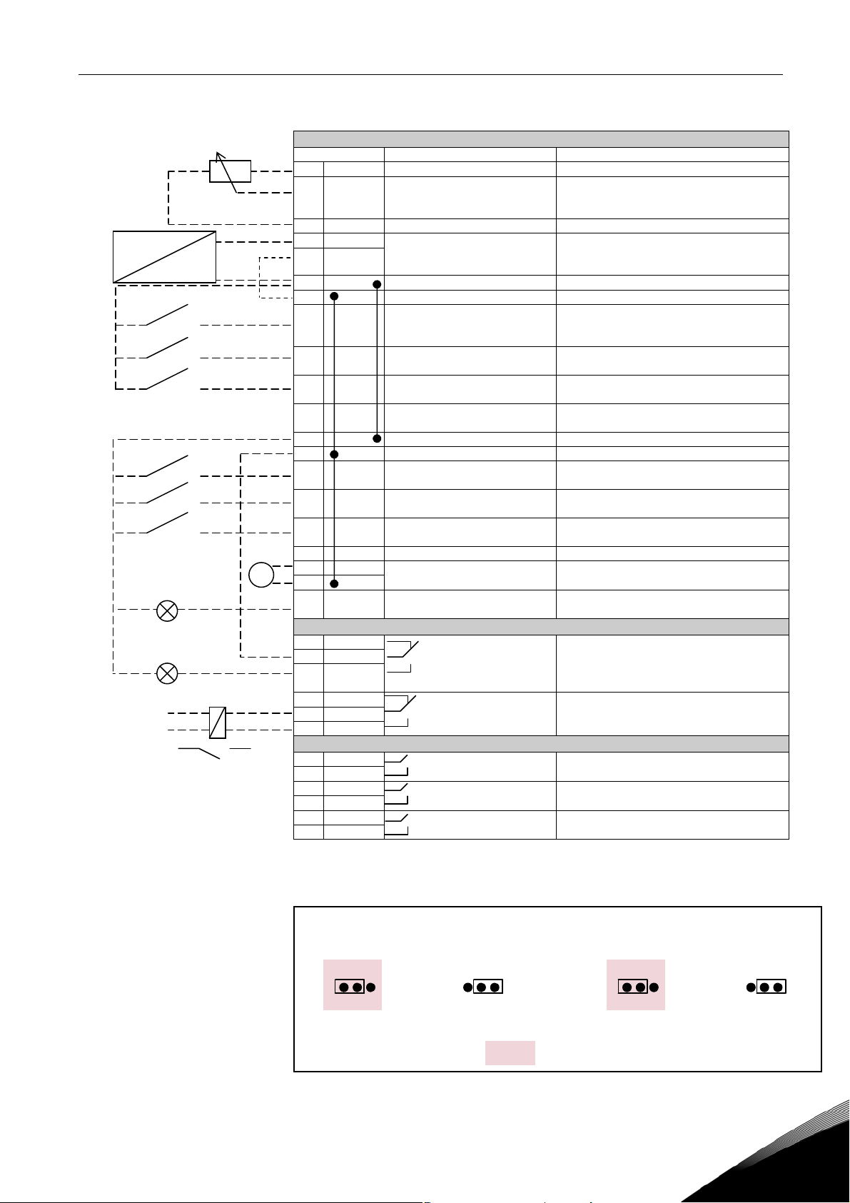
2. CONTROL I/O
Reference potentiometer,
1…10 kΩ
2-wire
transmitter
Actual
value I
(0)4…20 mA
READY
RUN
220
VAC
OPT-A1
Terminal Signal Description
1 +10V
2 AI1+ Analogue input, voltage range
3 AI1- I/O Ground Ground for reference and controls
–
4 AI2+ Analogue input, current range
5 AI2-
+
6 +24V Control voltage output Voltage for switches, etc. max 0.1 A
7 GND I/O ground Ground for reference and controls
8 DIN1 Start/Stop
9 DIN2 Flow fault NO/NC programmable
10 DIN3 External fault
11 CMA Common for DIN 1—DIN 3 Connect to GND or +24V
12 +24V Control voltage output Voltage for switches (see #6)
13 GND I/O ground Ground for reference and controls
14 DIN4 Pump 1
15 DIN5 Pump 2
16 DIN6 Sequence, 2-pump system Combined with DIN1
17 CMB Common for DIN4—DIN6 Connect to GND or +24V
mA
18 AO1+ Output frequency
19 AO120 DO1 Digital output
Reference output Voltage for potentiometer, etc.
ref
0—10V DC
0—20mA
Control place A (PID
controller)
(programmable)
Analogue output
READY
Pressure, outlet (pump)
Temperature
Contact closed = start
Contact open = External fault
Forced or single run
Combined with DIN1
Forced or single run
Combined with DIN1
Programmable
Range 0—20 mA/R
Programmable
Open collector, I≤50mA, U≤48 VDC
, max. 500Ω
L
OPT-A2
21 RO1 Relay output 1
22 RO1
23 RO1
24 RO2 Relay output 2
25 RO2
26 RO2
FAULT
Programmable
RUN
Programmable
OPT-B5
22 RO1 Relay output 1
23 RO1
25 RO2 Relay output 2
26 RO2
28 RO3 Relay output 3
29 RO3
COOLING OK
PUMP 1
PUMP 2
Table 1. Heat exchanger application I/O configuration example (with 2-wire
transmitter).
Ju m per block X 3:
CAN g rounding
Con nected to shiel d Not c o nnec ted to shi el d
24-hour support: +358 (0)201 212 575 • Email: vacon@vacon.com
Factory d efault
=
Ju m per block X 4:
CA N t erm i na ti on
Terminated Not terminated
2
Page 6
4 • vacon Parameter lists
3. PARAMETER LISTS
On the next pages you will find the lists of parameters within the respective parameter groups. The
parameter descriptions are given on pages 21 to 52.
Column explanations:
Code = Location indication on the keypad; Shows the operator the present param. number
Parameter = Name of parameter
Min = Minimum value of parameter
Max = Maximum value of parameter
Unit = Unit of parameter value; Given if available
Default = Value preset by factory
Cust = Customer’s own setting
ID = ID number of the parameter
= In parameter row: Use TTF method to program these parameters.
= On parameter code: Parameter value can only be changed after the FC has been
stopped.
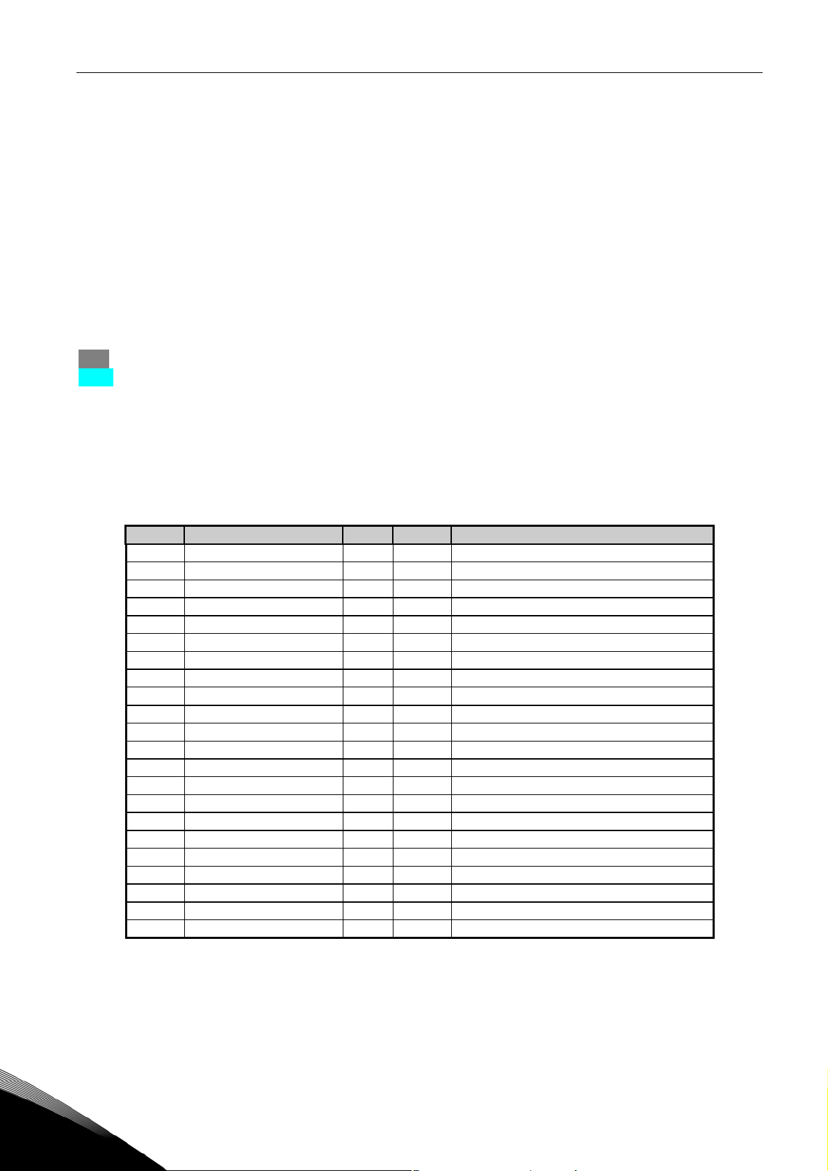
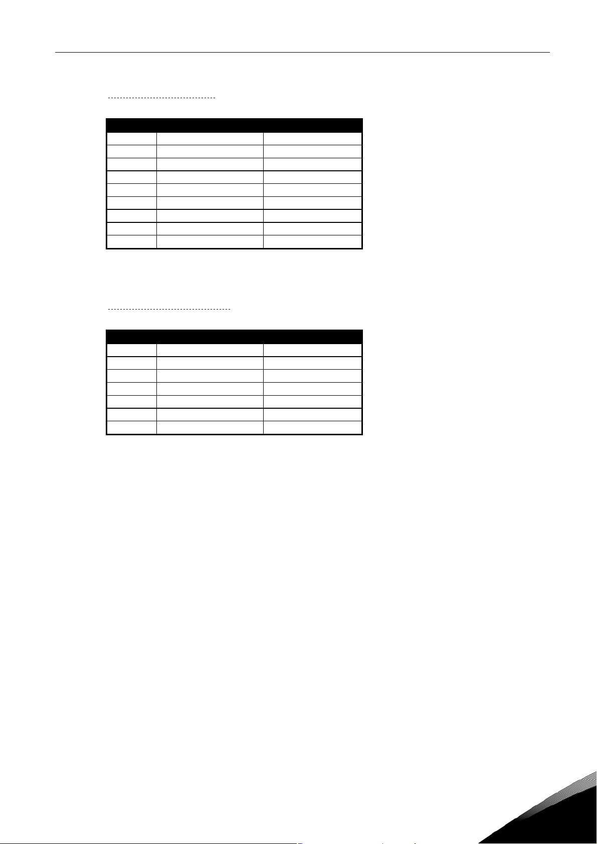
3.1 Monitoring values (Control keypad: menu M1)
The monitoring values are the actual values of parameters and signals as well as statuses and
measurements. Monitoring values cannot be edited.
See the product’s user manual for more information.
Code Parameter Unit ID Description
V1.1 Output frequency Hz 1 Output frequency to motor
V1.2 Frequency reference Hz 25 Frequency reference to motor control
V1.3 Motor speed rpm 2 Motor speed in rpm
V1.4 Motor current A 3
V1.5 Motor torque % 4 Calculated shaft torque
V1.6 Motor power % 5 Motor shaft power
V1.7 Motor voltage V 6
V1.8 DC link voltage V 7
V1.9
V1.10 Analogue input 1 V 13 AI1
V1.11 Analogue input 2 mA 14 AI2
V1.12 Analogue input 3 1543 AI3
V1.13 Analog Output1 26
V1.14 DIN1, DIN2, DIN3 15 Digital input statuses
V1.15 DIN4, DIN5, DIN6 16 Digital input statuses
V1.16 RO1, RO2, RO3 1516 Relay output statuses
V1.17 RO4, RO5, RO6 1574 Relay output statuses
V1.18 Temp reference °C 1500
V1.19 Actual temperature °C 1501
V1.20 Temp error value °C 1502
V1.21 PID output % 23 In % of the max. output value
V1.22 Inlet pressure bar 1511 PT11
Unit temperature
Table 2. Monitoring values
8 Heatsink temperature
°C
3
Tel. +358 (0)201 2121 • Fax: +358 (0)201 2121 205
Page 7
Parameter lists vacon • 5
3.1.1
FB Monitor
Code Parameter Unit ID Description
V1.23.1 Motor Current A 45 Motor current with one decimal
V1.23.2 Fault History 37 Last active fault code
V1.23.3 Status Word 43 Application status word
V1.23.4 Status Word 2 1800 Application status word 2
V1.23.5 Fault Word 1 1172 General fault word 1
V1.23.6 Fault Word 2 1173 General fault word
V1.23.7 Warning Word 1 1174 General warning word
V1.23.8 Fault Word 10 1202 Heat exchanger specific faults
V1.23.9 Warning Word 10 1269 Heat exchanger specific warnings
Table 3. Monitoring values (G1.24 FB Monitor)
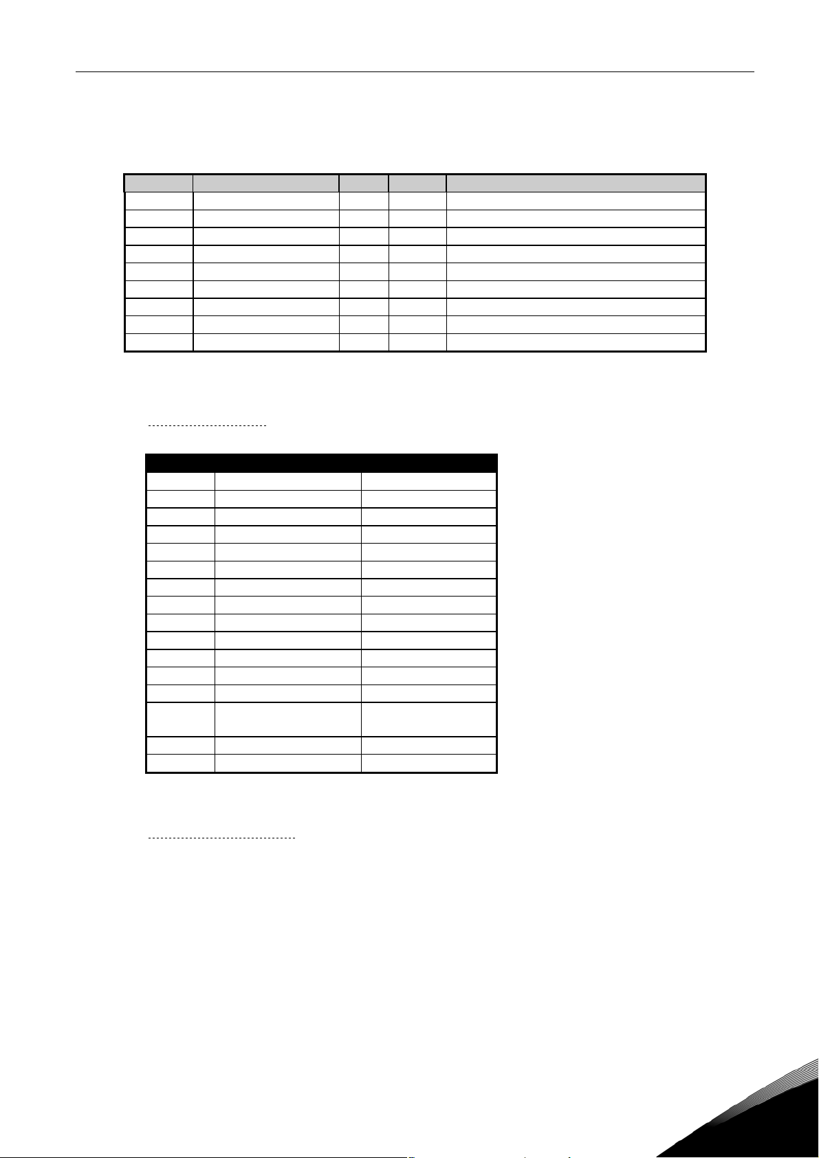
3.1.1.1 Status Word, ID43
Description Comment
b0
b1 Ready
b2 Run
b3 Fault
b4
b5
b6 Run enable
b7 Warning
b8
b9
b10 RO4 status
b11 RO5 status
b12 Run request
b13
b14
b15 Cooling OK
Motor regulator
active
Table 4. Status Word
3.1.1.2 Status Word 2, ID1800
Give this status word to Vacon personnel in case of problems with running the application.
24-hour support: +358 (0)201 212 575 • Email: vacon@vacon.com
3
Page 8
6 • vacon Parameter lists
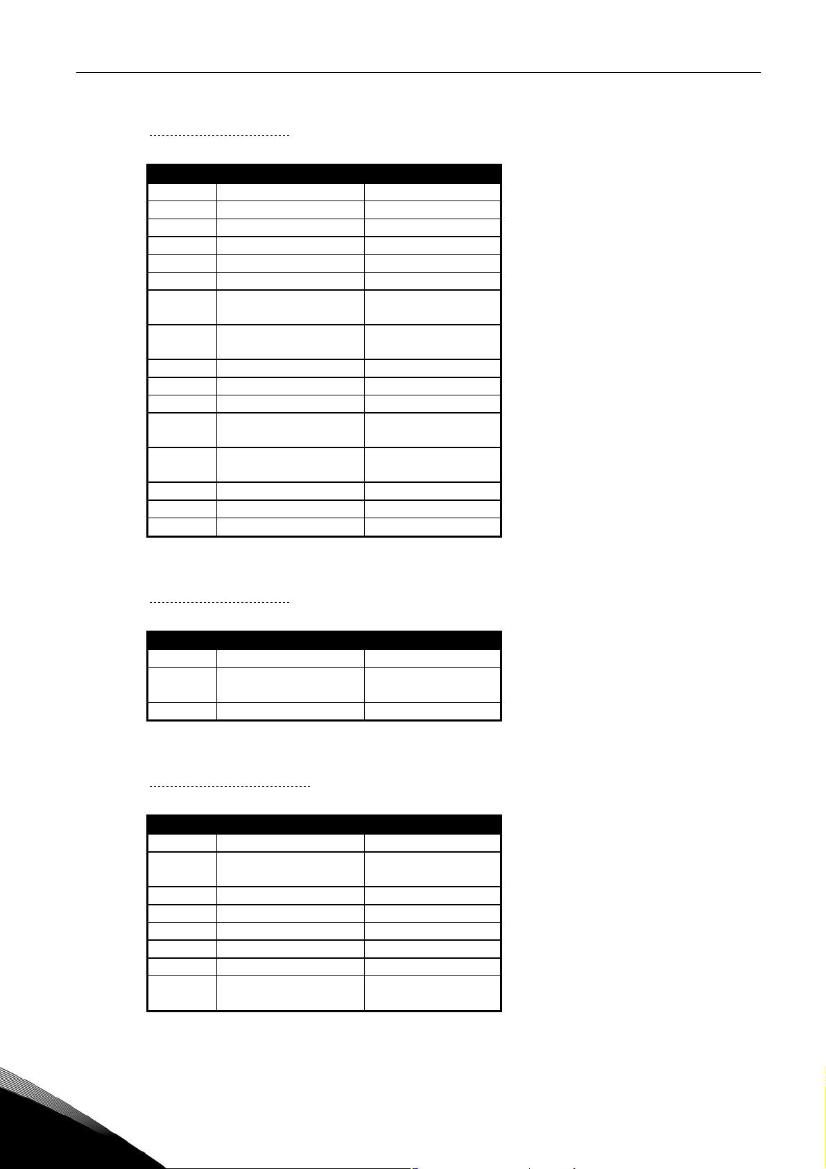
3.1.1.3 Fault Word 1, ID1172
Description Comment
b0 Over current F1
b1 Over voltage F2
b2 Under voltage F9
b3 Motor stalled F15
b4
b5 Motor underload F17
b6
b7
b8 Input phase F10
b9
b10
b11
b12
b13
b14 Slot communication F54
b15 4 mA F50
Unit over
temperature
Motor over
temperature
Keypad or PC
communication
Fieldbus
communication
F16
F52
F53
Table 5. Fault Word 1
3.1.1.4 Fault Word 2, ID1173
Description Comment
b0 Output phase F11
b6 External fault
b9 IGBT F41
Table 6. Fault Word 2
3.1.1.5 Warning Word 1, ID1174
Description Comment
b0 Motor stalled F15
b1
b2 Motor underload F17
b3 Input phase F10
b4 Output phase F11
b8 Unit temperature
b9 4 mA F50
b15
Motor over
temperature
Keypad
communication
Table 7. Warning Word 1
F51
(fault or warning)
F16,
F29 (fault or warn)
F52
3
Tel. +358 (0)201 2121 • Fax: +358 (0)201 2121 205
Page 9
Parameter lists vacon • 7
3.1.1.6 Fault Word 10, ID1202
Description Comment
b0
b1
b2
b3
b4
b5 Over temperature F85 (warning)
b6
b7 Inlet pressure low F88
b8 Flow F87
Table 8. Fault Word 10
3.1.1.7 Warning Word 10, ID1269
Description Comment
b0
b1
b2
b3 Inlet pressure low F82
b4 Over temperature F83
b5 Low temperature F86
b6
Table 9. Warning Word 10
24-hour support: +358 (0)201 212 575 • Email: vacon@vacon.com
3
Page 10
8 • vacon Parameter lists
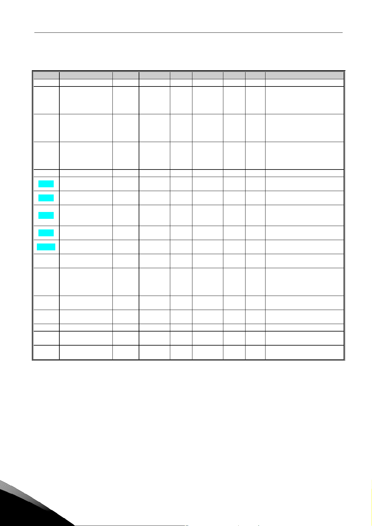
3.2 Basic parameters (Control keypad: Menu M2 G2.1)
Code Parameter Min Max Unit Default Cust ID Note
P2.1.1 Min Frequency 0.00 Par. 2.1.2 Hz 25.00 101
NOTE: If f
P2.1.2 Max Frequency Par. 2.1.1 320.00 Hz 50.00 102
P2.1.3 Acceleration time 1 0.1 3000.0 s 1.0 103
P2.1.4 Deceleration time 1 0.1 3000.0 s 1.0 104
P2.1.5 Current limit 0 2 x I
P2.1.6
P2.1.7
P2.1.8
P2.1.9
P2.1.10
P2.1.11 Start function 0 1 0 505
P2.1.12 Stop function 0 3 0 506
P2.1.13 U/f optimization 0 1 0 109
P2.1.14 I/O reference 0 1 0 117
P2.1.15 Preset speed1 0.00 Par. 2.1.2 Hz 10.00
P2.1.16 Automatic restart 0 1 0
P2.1.17 Parameter conceal 0 1 1
Nominal voltage of
the motor
Nominal frequency
of the motor
Nominal speed of
the motor
Nominal current of
the motor
Motor cosϕ
180 690 V 400V 110
30.00 320.00 Hz 50.00 111
300 20 000 rpm 1440 112
0.4 x I
2 x IH A IH 113
H
0.30 1.00 0.85 120
H
AI
L
motor synchronous speed,
check suitability for motor
and drive system
NOTE: If PID-controller is
used, Acceleration time 2
(par. 2.4.3) is automatically
applied
NOTE: If PID-controller is
used, Deceleration time 2
(par. 2.4.4) is automatically
applied
107
Check the rating plate of the
motor
The default applies for a 4pole motor and a nominal
size AC drive.
Check the rating plate of the
motor.
Check the rating plate of the
motor
0=Ramp
1=Flying start
0=Coasting
1=Ramp
2=Ramp+Run enable coast
3=Coast+Run enable ramp
0=Not used
1=Automatic torque boost
0=Keypad reference
1=Fieldbus reference
105
0=Not used
731
1=Automatic restart
0=All parameters visible
115
1=Basic group (G2.1) visible
> than the
max
Table 10. Basic parameters G2.1
3
Tel. +358 (0)201 2121 • Fax: +358 (0)201 2121 205
Page 11
Parameter lists vacon • 9
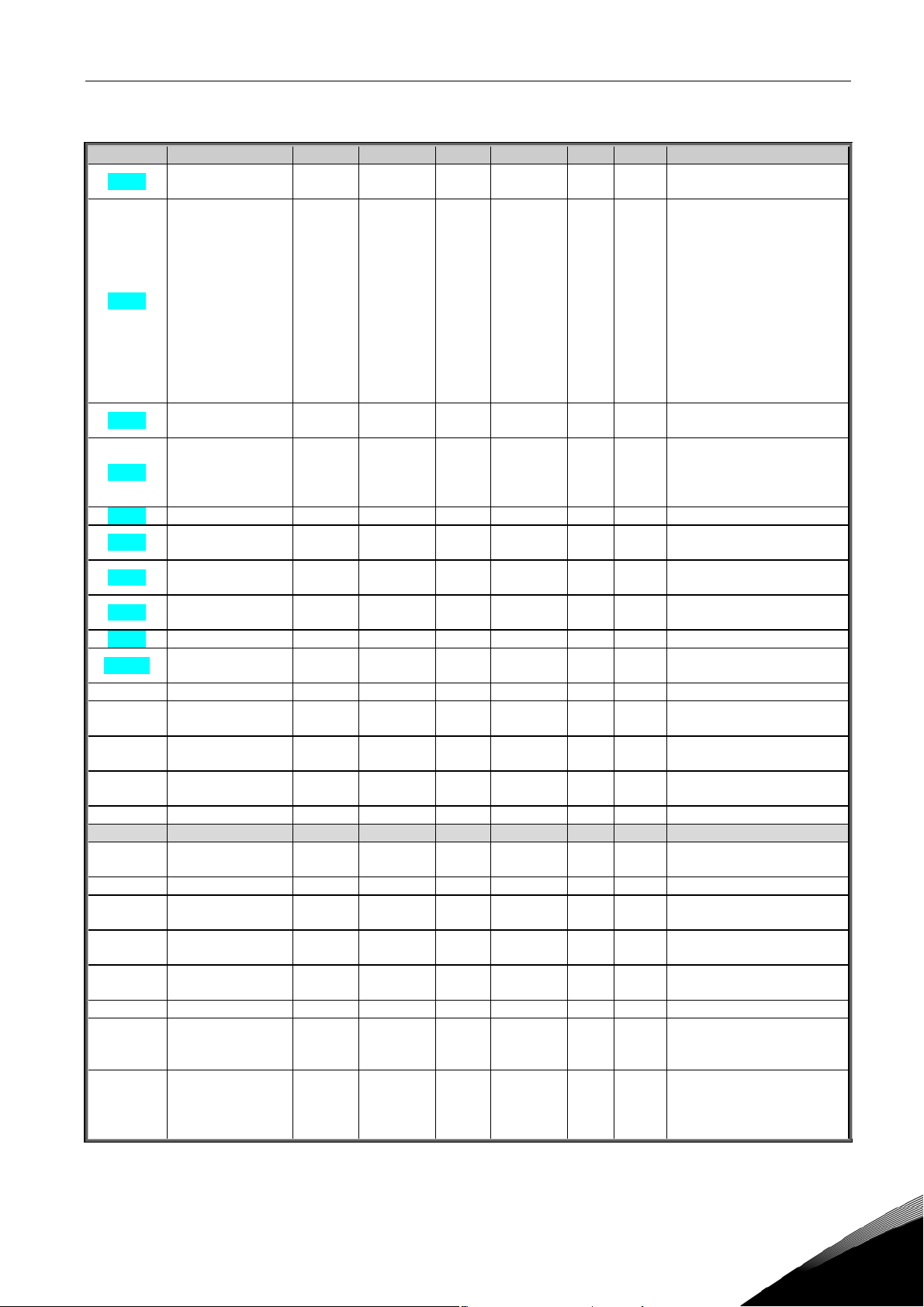
3.3 Input signals (Control keypad: Menu M2 G2.2)
Code Parameter Min Max Unit Default Cust ID Note
P2.2.1 DIN2 input 0 1 1 1590
P2.2.2 DIN3 function 0 10 3 301
P2.2.3 DIN6 Function 0 1 0 1572
P2.2.4 AI1 signal range 0 3 1 379
P2.2.5 AI1 supervision 0 1 0 1544
P2.2.6
P2.2.7
P2.2.8 AI1 inversion 0 1 0 387
P2.2.9 AI1 filter time 0.00 10.00 s 1.00 378 0=No filtering
P2.2.10 AI2 signal range 0 1 1 390
P2.2.11 AI2 supervision 0 1 1 1545
P2.2.12
P2.2.13
P2.2.14 AI2 inversion 0 1 0 398
P2.2.15 AI2 filter time 0.00 10.00 s 1.00 389 0=No filtering
P2.2.16 AI3 signal selection 0 59 1558 TTF programming method
P2.2.17 AI3 signal range 0 1 1 1520
P2.2.18 AI3 supervision 0 1 0 1546
P2.2.19
P2.2.20
P2.2.21 AI3 inversion 0 1 0 1529
P2.2.22 AI3 filter time 0.00 10.00 s 1.00 1526 0=No filtering
P2.2.23
P2.2.24
AI1 custom
minimum setting
AI1 custom
maximum setting
AI2 custom
minimum setting
AI2 custom
maximum setting
AI3 custom
minimum setting
AI3 custom
maximum setting
Keypad control
reference
Fieldbus control
reference
0.00 P2.2.6 % 0.00 380
0.00 100.00 % 100.00 381
0.00 P2.2.6 % 0.00 391
0.00 100.00 % 100.00 392
0.00 P2.2.18 % 0.00 1517
P2.2.17 100.00 % 100.00 1518
0 1 0 121
0 1 1 122
0=Normally open
1=Normally closed
0=Motor pot. UP(cc)
1=Reverse
2=External fault CC
3=External fault OC
4=Fault reset
5=Run enable
6=Preset speed 1
7=DC brake cmnd
8=PID disable
9=PID disable, go to preset
speed
10=PID keypad ref 2
0=Preset Speed 1
1=Fault Reset
0=Signal range 0-20mA
1=Signal range 4-20mA
2=0-10V
3=2-10V
0=Not inverted
1=Inverted
0=Signal range 0-20mA
1=Signal range 4-20mA
0=Not inverted
1=Inverted
0=Signal range 0-20mA
1=Signal range 4-20mA
0=Not inverted
1=Inverted
Keypad freq ref selection:
0=Reference from Keypad
1=FB reference
Fieldbus frequency
reference selection:
0=Reference from Keypad
1=FB reference
Table 11. Input signals, G2.2
*Remember to place jumpers of block X2 accordingly.
See the product's user manual.
24-hour support: +358 (0)201 212 575 • Email: vacon@vacon.com
3
Page 12
10 • vacon Parameter lists
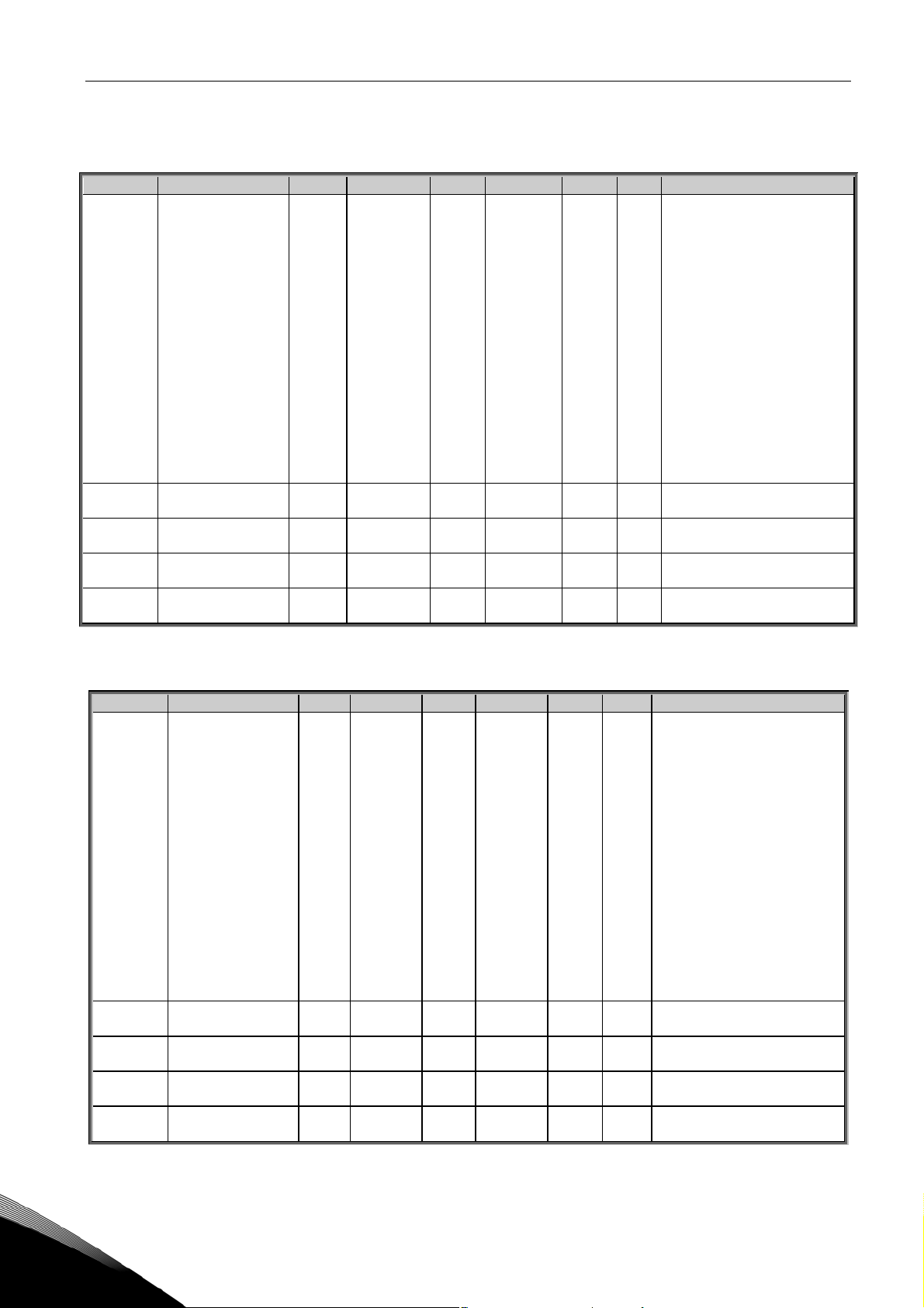
3.4 Output signals (Control keypad: Menu M2 G2.3)
3.4.1
Analogue output 1
Code Parameter Min Max Unit Default Cust ID Note
0=Not used
1=Output freq. (0—f
2=Freq. reference (0—f
max
)
)
max
3=Motor speed (0—Motor
nominal speed)
P2.3.1.1
Analogue output 1
function
4=Motor current (0—I
5=Motor torque (0—T
6=Motor power (0—P
0 13 13 307
7=Motor voltage (0-U
8=DC-link volt (0—1000V)
nMotor
nMotor
nMotor
nMotor
)
)
)
)
9=PI controller temp ref
10=PI contr. act. temp.
11=PI contr. temperature
error value
12=PI controller output
13=Pressure from PT11,
pump inlet
P2.3.1.2
P2.3.1.3
P2.3.1.4
P2.3.1.5
Analogue output 1
filter time
Analogue output 1
inversion
Analogue output 1
minimum
Analogue output 1
scale
0.00 10.00 s 1.00 308 0=No filtering
0 1 0 309
0 1 1 310
0=Not inverted
1=Inverted
0=0 mA
1=4 mA
10 1000 % 100 311
Table 12. Analogue output 1 signals
3.4.2
Analogue output 2
Code Parameter Min Max Unit Default Cust ID Note
0=Not used
1=Output freq. (0—f
2=Freq. reference (0—f
3=Motor speed (0—Motor
nominal speed)
4=Motor current (0—I
5=Motor torque (0—T
6=Motor power (0—P
7=Motor voltage (0-U
8=DC-link volt (0—1000V)
P2.3.2.1
Analogue output 2
function
0 13 10 1530
9=PID controller ref. value
10=PI contr. act. temp
11=PI contr. temperature
error value
12=PI controller output
13=Pressure from PT11,
pump inlet
P2.3.2.2
P2.3.2.3
P2.3.2.4
P2.3.2.5
Analogue output 2
filter time
Analogue output 2
inversion
Analogue output 2
minimum
Analogue output 2
scale
0.00 10.00 s 1.00 1531 0=No filtering
0 1 0 1532
0 1 0 1533
0=Not inverted
1=Inverted
0=0 mA
1=4 mA
10 1000 % 100 1534
Table 13. Analogue output 2 signals
max
)
max
nMotor
nMotor
nMotor
nMotor
)
)
)
)
)
3
Tel. +358 (0)201 2121 • Fax: +358 (0)201 2121 205
Page 13
Parameter lists vacon • 11
3.4.3
Analogue output 3
Code Parameter Min Max Unit Default Cust ID Note
0=Not used
P2.3.3.1
P2.3.3.2
P2.3.3.3
P2.3.3.4
P2.3.3.5
Analogue output 3
function
Analogue output 3
filter time
Analogue output 3
inversion
Analogue output 3
minimum
Analogue output 3
scale
1=Output freq. (0—f
2=Freq. reference (0—f
3=Motor speed (0—Motor
nominal speed)
4=Motor current (0—I
5=Motor torque (0—T
6=Motor power (0—P
0 13 4 1535
0.00 10.00 s 1.00 1536 0=No filtering
0 1 0 1537
0 1 0 1538
10 1000 % 100 1539
7=Motor voltage (0-U
8=DC-link volt (0—1000V)
9=PID controller ref. value
10=PI contr. act. temp
11=PI contr. temperature
error value
12=PID controller output
13=Pressure from PT11,
pump inlet
0=Not inverted
1=Inverted
0=0 mA
1=4 mA
max
)
max
nMotor
nMotor
nMotor
nMotor
)
)
)
)
)
Table 14. Analogue output 3 signals
3.4.4
Relay output 1
Code Parameter Min Max Unit Default Cust ID Note
P2.3.4.1
P2.3.4.2
P2.3.4.3
Relay output 1
signal selection
Relay output 1
function
Relay output 1
inversion
B.1 1549
0=Not used
1=Ready
2=Run
3=Fault
4=Fault inverted
5=FC overheat warning
6=Ext. fault or warning
7=Ref. fault or warning
8=Warning
0 18 2 313
0 1 0 1540
9=Reversed
10=Preset speed 1
11=At speed
12=Mot. regulator active
13=OP freq. limit superv.1
14=Control place: IO
15=Thermistor fault/warn.
16=Actual value supervision
17=Cooling OK
18=Alarm latched
0=Not inverted
1=Inverted
Table 15. Relay output 1 signals
24-hour support: +358 (0)201 212 575 • Email: vacon@vacon.com
3
Page 14
12 • vacon Parameter lists
3.4.5
Relay output 2
Code Parameter Min Max Unit Default Cust ID Note
P2.3.5.1
P2.3.5.2
P2.3.5.3
Relay output 2
signal selection
Relay output 2
function
Relay output 2
inversion
B.2 1550
0=Not used
1=Ready
2=Run
3=Fault
4=Fault inverted
5=FC overheat warning
6=Ext. fault or warning
7=Ref. fault or warning
8=Warning
0 18 3 1513
0 1 0 1541
9=Reversed
10=Preset speed 1
11=At speed
12=Mot. regulator active
13=OP freq. limit superv.1
14=Control place: IO
15=Thermistor fault/warn.
16=Actual value supervision
17=Cooling OK
18=Alarm latched
0=Not inverted
1=Inverted
Table 16. Relay output 2 signals
3.4.6
Relay output 3
Code Parameter Min Max Unit Default Cust ID Note
P2.3.6.1
P2.3.6.2
P2.3.6.3
Relay output 3
signal selection
Relay output 3
function
Relay output 3
inversion
D.1 1551
0=Not used
0 3 1 1515
0 1 0 1542
1=Cooling OK
2=Pump 1
3=Pump 2
0=Not inverted
1=Inverted
Table 17. Relay output 3 signals
3.4.7
Relay output 4
Code Parameter Min Max Unit Default Cust ID Note
P2.3.7.1
P2.3.7.2
P2.3.7.3
Relay output 4
signal selection
Relay output 4
function
Relay output 4
inversion
D.2 1552
0=Not used
0 3 2 1553
0 1 0 1554
1=Cooling OK
2=Pump 1
3=Pump 2
0=Not inverted
1=Inverted
Table 18. Relay output 4 signals
3
Tel. +358 (0)201 2121 • Fax: +358 (0)201 2121 205
Page 15
Parameter lists vacon • 13
3.4.8
Relay output 5
Code Parameter Min Max Unit Default Cust ID Note
P2.3.8.1
P2.3.8.2
P2.3.8.3
Relay output 5
signal selection
Relay output 5
function
Relay output 5
inversion
D.3 1555
0=Not used
0 3 3 1556
0 1 0 1557
1=Cooling OK
2=Pump 1
3=Pump 2
0=Not inverted
1=Inverted
Table 19. Relay output 5 signals
3.4.9
Relay output 6
Code Parameter Min Max Unit Default Cust ID Note
P2.3.9.1
P2.3.9.2
P2.3.9.3
Relay output 6
signal selection
Relay output 6
function
Relay output 6
inversion
A.1 1573
0=Not used
1=Ready
2=Run
3=Fault
4=Fault inverted
5=FC overheat warning
6=Ext. fault or warning
7=Ref. fault or warning
8=Warning
0 18 3 1567
0 1 0 1568
9=Reversed
10=Preset speed 1
11=At speed
12=Mot. regulator active
13=OP freq. limit superv.1
14=Control place: IO
15=Thermistor fault/warn.
16=Actual value supervision
17=Cooling OK
18=Alarm latched
0=Not inverted
1=Inverted
Table 20. Relay output 6 signals
24-hour support: +358 (0)201 212 575 • Email: vacon@vacon.com
3
Page 16
14 • vacon Parameter lists
3.5 Drive control parameters (Control keypad: Menu M2 G2.4)
Code Parameter Min Max Unit Default Cust ID Note
P2.4.1 Ramp 1 shape 0.0 10.0 s 0.0 500
P2.4.2 Brake chopper 0 3 0 504
P2.4.3 DC braking current 0.4 x IH 2 x I
P2.4.4
P2.4.5
P2.4.6
P2.4.7 Flux brake 0 1 0 520
P2.4.8 Flux braking current 0.4 x IH 2 x I
DC braking time
at stop
Frequency to start
DC braking during
ramp stop
DC braking time
at start
0.00 600.00 s 0.00 508 0=DC brake is off at stop
0.10 10.00 Hz 1.50 515
0.00 600.00 s 0.00 516 0=DC brake is off at start
H
H
AI
AI
H
H
0=Linear
>0=S-curve ramp time
0=Disabled
1=Used when running
2=External brake chopper
3=Used when stopped/
running
507
0=Off
1=On
519
Table 21. Drive control parameters, G2.4
3.6 Prohibit frequency parameters (Control keypad: Menu M2 G2.5)
Code Parameter Min Max Unit Default Cust ID Note
P2.5.1
P2.5.2
P2.5.3
P2.5.4
P2.5.5
Prohibit frequency
range 1 low limit
Prohibit frequency
range 1 high limit
Prohibit acc./dec.
ramp
Output frequency
limit 1 supervision
Output frequency
limit 1;
Supervised value
0.00 Par. 2.5.2 Hz 0.00 509 0=Not used
0.00 Par. 2.1.2 Hz 0.00 510 0=Not used
0.1 10.0 Times 1.0 518
0=No limit
0 2 0 315
0.00 Par. 2.1.2 Hz 0.00 316
1=Low limit supervision
2=High limit supervision
Table 22. Prohibit frequency parameters, G2.5
3
Tel. +358 (0)201 2121 • Fax: +358 (0)201 2121 205
Page 17
Parameter lists vacon • 15
3.7 Motor control parameters (Control keypad: Menu M2 G2.6)
Code Parameter Min Max Unit Default Cust ID Note
P2.6.1 Motor control mode 0 1 0 600
P2.6.2 U/f ratio selection 0 3 0 108
P2.6.3 Field weakening point 8.00 320.00 Hz 50.00 602
P2.6.4
P2.6.5
P2.6.6
P2.6.7
P2.6.8 Switching frequency 1.0 Varies kHz Varies 601
P2.6.9 Overvoltage controller 0 1 1 607
P2.6.10
Voltage at field
weakening point
U/f curve midpoint
frequency
U/f curve midpoint
voltage
Output voltage at zero
frequency
Undervoltage
controller
10.00 200.00 % 100.00 603 n% x U
0.00
0.00 100.00 % 100.00 605
0.00 40.00 % Varies 606 n% x U
0 1 1 608
par.
P2.6.4
Hz 50.00 604
0=Frequency control
1=Speed control
0=Linear
1=Squared
2=Programmable
3=Linear with flux optim.
nmot
n% x U
nmot
Parameter max. value =
par. 2.6.5
nmot
See Table 31 for exact
values
0=Not used
1=Used (no ramping)
0=Not used
1=Used
Table 23. Motor control parameters, G2.6
24-hour support: +358 (0)201 212 575 • Email: vacon@vacon.com
3
Page 18

16 • vacon Parameter lists
3.8 Protections (Control keypad: Menu M2 G2.7)
Code Parameter Min Max Unit Default Cust ID Note
0=No response
P2.7.1
P2.7.2
P2.7.3
P2.7.4
P2.7.5
P2.7.6
P2.7.7
P2.7.8
P2.7.9
P2.7.10
P2.7.11 Motor duty cycle 0 100 % 100 708
P2.7.12 Stall protection 0 3 1 709 See par. ID700
P2.7.13 Stall current 0.1 I
P2.7.14 Stall time limit 1.00 120.00 s 15.00 711
P2.7.15 Stall frequency limit 1.0 Par. 2.1.2 Hz 25.0 712
P2.7.16
P2.7.17
P2.7.18 Zero frequency load 5.0 150.0 % 10.0 715
P2.7.19
P2.7.20
P2.7.21
P2.7.22 Resp. to slot fault 0 3 2 734 See par. ID700
P2.7.23
P2.7.24
P2.7.25
Response to 4mA
reference fault
Response to
external fault
Input phase
supervision
Response to
undervoltage fault
Output phase
supervision
Earth fault
protection
Thermal protection
of the motor
Motor ambient
temperature factor
Motor cooling factor
at zero speed
Motor thermal time
constant
Underload
protection
Field weakening
area load
Underload protec-
tion time limit
Response to
thermistor fault
Response to
fieldbus fault
Actual value
supervision
function
Actual value
supervision limit
Actual value
supervision delay
0 3 1 700
0 3 1 701 See par. ID700
0 3 0 730 See par. ID700
1 3 2 727
0 3 2 702 See par. ID700
0 3 2 703 See par. ID700
0 3 2 704 See par. ID700
–100.0 100.0 % 0.0 705
0.0 150.0 % 40.0 706
1 200 min Varies 707
x 2 A I
nMotor
0 3 0 713 See par. ID700
10 150 % 50 714
2 600 s 20 716
0 3 0 732 See par. ID700
0 3 2 733 See par. ID700
0 4 0 735
0 100.0 % 10.0 736
0 3600 s 5 737
L
1=Warning
2=Fault,stop acc. to 2.1.12
3=Fault,stop by coasting
1=Warning
2=Fault,stop acc. to 2.1.12
3=Fault,stop by coasting
710
0=Not used
1=If below limit: Warning
2=If above limit: Warning
3=If below limit: Fault
4=If above limit: Fault
Table 24. Protections, G2.7
3
Tel. +358 (0)201 2121 • Fax: +358 (0)201 2121 205
Page 19

Parameter lists vacon • 17
3.9 Autorestart parameters (Control keypad: Menu M2 G2.8)
Code Parameter Min Max Unit Default Cust ID Note
P2.8.1 Wait time 0.10 10.00 s 0.50 717
P2.8.2 Trial time 0.00 60.00 s 30.00 718
0=Ramp
P2.8.3 Start function 0 2 0 719
1=Flying start
2=According to par. 2.1.11
Table 25. Autorestart parameters, G2.8
3.10 PID control parameters (Control keypad: Menu M2 G2.9)
Code Parameter Min Max Unit Default Cust ID Note
P2.9.1 PID activation 0 1 1 163
P2.9.2 PID reference 0 2 0 332
P2.9.3
P2.9.4 PID controller gain 0.0 1000.0 % 100.0 118 0=No part P used
P2.9.5
P2.9.6
P2.9.7
P2.9.8
P2.9.9 Error value inversion 0 1 0 340
P2.9.10 Dead band 0 10.00 °C 0.0 1575 0=Not Used
P2.9.11 Dead band delay 0 100.00 s 10.0 1576
Actual value 1
selection
PID controller I-
time
PID controller D-
time
Actual value 1
minimum scale
Actual value 1
maximum scale
0 2 1 334
0.00 320.00 s 5.00 119 320.00=No part I used
0.00 10.00 s 0.00 132 0=No part D used
–1000.0 1000.0 % 0.0 336 0=No minimum scaling
–1000.0 1000.0 % 100.0 337 100=No maximum scaling
0=Not used
1=PID control activated
0=PID ref from Keypad
control page, par. 3.4
1=PID ref from Keypad
control page, par 3.5
2=PID ref from fieldbus
(ProcessDataIN 1)
0=AI1 signal (c-board)
1=AI2 signal (c-board)
2=Fieldbus
0=No inversion
1=Inversion
ProcessDataIN2
Table 26. PID control parameters, G2.9
24-hour support: +358 (0)201 212 575 • Email: vacon@vacon.com
3
Page 20

18 • vacon Parameter lists
3.11 Flow control parameters (Control keypad: Menu M2 G2.10)
Code Parameter Min Max Unit Default Cust ID Note
P2.10.1 Constant speed Par. 2.1.1 Par. 2.1.1 Hz 50.00 1514
P2.10.2
P2.10.3
P2.10.4
P2.10.5
P2.10.6
P2.10.7
P2.10.8
P2.10.9
P2.10.10
P2.10.11
P2.10.12 Autochange interval 0 169 h 169 1599
P2.10.13 Delayed fault 1 30 s 2 1503
Coolant inlet pressure,
minimum
Coolant inlet pressure,
maximum
Coolant inlet pressure,
alarm limit
Coolant inlet pressure,
fault limit
Coolant inlet pressure,
supervision
Temperature sensor,
minimum value
Temperature sensor,
maximum value
Coolant outlet
temperature alarm,
lower limit
Coolant outlet
temperature alarm,
higher limit
Coolant outlet
temperature fault,
higher limit
0.00
Par.
2.10.2
0.00 100.00 bar 1.00 1570
0.00 100.00 bar 2.00 1571
0 1 0 1569
0.00 Par. 2.10.7 °C 0.00 1509
Par.
2.10.6
0.00 100.00 °C 22.00 1591
0.00 100.00 °C 30.00 1594
0.00 100.00 °C 40.00 1595
Par.
2.10.3
30.00 bar 10.00 1505
100.00 °C 100.00 1510
bar 0.00 1504
0=Off (No sensor)
1=On (Sensor installed)
0=Test mode
169=Single motor, no
change
Table 27. Flow control parameters, G2.10
3
Tel. +358 (0)201 2121 • Fax: +358 (0)201 2121 205
Page 21

Parameter lists vacon • 19
3.12 Fieldbus parameters (Control Keypad: Menu M2 G2.11)
Code Parameter Min Max Unit Default Cust ID Note
P2.11.1
P2.11.2
P2.11.3
P2.11.4
P2.11.5
P2.11.6
P2.11.7
P2.11.8
Fieldbus data out 1
selection
Fieldbus data out 2
selection
Fieldbus data out 3
selection
Fieldbus data out 4
selection
Fieldbus data out 5
selection
Fieldbus data out 6
selection
Fieldbus data out 7
selection
Fieldbus data out 8
selection
0 10000 1501 852
0 10000 2 853
0 10000 45 854
0 10000 1511 855
0 10000 1 856
0 10000 4 857
0 10000 5 858
0 10000 37 859
Choose monitoring data
with parameter ID
Choose monitoring data
with parameter ID
Choose monitoring data
with parameter ID
Choose monitoring data
with parameter ID
Choose monitoring data
with parameter ID
Choose monitoring data
with parameter ID
Choose monitoring data
with parameter ID
Choose controlled data
with parameter ID
Table 28. Fieldbus parameters, G2.11
24-hour support: +358 (0)201 212 575 • Email: vacon@vacon.com
3
Page 22

20 • vacon Parameter lists
3.13 Keypad control (Control keypad: Menu M3)
The parameters for the selection of control place and direction on the keypad are listed below. See
the Keypad control menu in the product's User Manual.
Code Parameter Min Max Unit Default Cust ID Note
1=I/O terminal
P3.1 Control place 1 3 1 125
R3.2 Keypad reference Par. 2.1.1 Par. 2.1.2 Hz
P3.3
R3.6 Stop button 0 1 1 114
R3.4 PID reference Par. 2.10.6 Par. 2.10.7 °C 25.00
R3.5 PID reference 2 Par. 2.10.6 Par. 2.10.7 °C 0.00
Direction (on
keypad)
0 1 0 123
2=Keypad
3=Fieldbus
0=Forward
1=Reverse
0=Limited function of
Stop button
1=Stop button always
enabled
Table 29. Keypad control parameters, M3
3.14 System menu (Control keypad: M6)
For parameters and functions related to the general use of the AC drive, such as application and
language selection, customised parameter sets or information about the hardware and software,
see the product's User manual.
3.15 Expander boards (Control keypad: Menu M7)
The M7 menu shows the expander and option boards attached to the control board and boardrelated information. For more information, see the product's User Manual.
3
Tel. +358 (0)201 2121 • Fax: +358 (0)201 2121 205
Page 23

Description of parameters vacon • 21
4. DESCRIPTION OF PARAMETERS
On the following pages you will find the parameter descriptions arranged according to the individual
ID number of the parameter. A shaded parameter ID number (e.g.
indicates that the
Manual).
Some parameter names are followed by a number code indicating the "All in One" applications in
which the parameter is included. If no code is shown the parameter is available in all applications.
See below. The parameter numbers under which the parameter appears in different applications are
also given.
101 Minimum frequency
102 Maximum frequency
Defines the frequency limits of the AC drive.
The maximum value for these parameters is 320 Hz.
The software will automatically check the values of parameters ID105, ID106 and ID728.
103 Acceleration time 1
104 Deceleration time 1
TTF programming method
(2.1.3)
(2.1.4)
is applied to this parameter (see All-in-One Application
(2.1.1)
(2.1.2)
418 Motor potentiometer UP
)
These limits correspond to the time required for the output frequency to accelerate from
the zero frequency to the set maximum frequency (par. ID102).
105 Preset speed 1
Parameter values are automatically limited between the minimum and maximum
frequencies (par. ID101, ID102).
(2.1.15)
107 Current limit
This parameter determines the maximum motor current from the AC drive. The
parameter value range differs from size to size. When this parameter is changed the
stall current limit (ID710) is internally calculated to 90% of current limit.
108 U/f ratio selection
Linear: 0 The voltage of the motor changes linearly with the frequency in the constant
flux area from 0 Hz to the field weakening point where the nominal voltage is
supplied to the motor. Linear U/f ration should be used in constant torque
applications. Use this default setting if there is no special need for
another setting.
Squared: 1 The voltage of the motor changes following a squared curve form with the
frequency in the area from 0 Hz to the field weakening point where the nominal voltage is also supplied to the motor. The motor runs undermagnetised
below the field weakening point and produces less torque and electromechanical noise. Squared U/f ratio can be used in applications where torque
demand of the load is proportional to the square of the speed, e.g. in
centrifugal fans and pumps.
(2.6.2)
(2.1.5
)
24-hour support: +358 (0)201 212 575 • Email: vacon@vacon.com
4
Page 24

22 • vacon Description of parameters
U[V]
Un
Default: Nominal
ID603
voltage of the motor
Linear
Field weakening
point
Squared
Default: Nominal
frequency of the
motor
NX12K07
f[Hz]
Figure 1. Linear and squared change of motor voltage
Programmable U/f curve:
2 The U/f curve can be programmed with three different points. Programmable
U/f curve can be used if the other settings do not satisfy the needs of the
application.
U[V]
Un
ID603
ID605
(Def. 10%)
ID606
(Def. 1.3%)
Default: Nominal
voltage of the motor
ID604
(Def. 5 Hz)
Field weakening point
Default: Nominal
frequency of the motor
ID602
f[Hz]
NX12K08
Figure 2. Programmable U/f curve
4
Linear with flux optimisation:
3 The AC drive starts to search for the minimum motor current in order to save
energy, lower the disturbance level and the noise. This function can be used
in applications with constant motor load, such as fans, pumps etc.
109 U/f optimisation
Automatic
torque boost
(2.1.13)
The voltage to the motor changes automatically which makes the motor
produce sufficient torque to start and run at low frequencies. The voltage
increase depends on the motor type and power. Automatic torque boost
can be used in applications where starting torque due to starting friction
is high, e.g. in conveyors.
Tel. +358 (0)201 2121 • Fax: +358 (0)201 2121 205
Page 25

Description of parameters vacon • 23
EXAMPLE:
What changes are required to start with load from 0 Hz?
♦ First set the motor nominal values (Parameter group 2.1).
Option 1: Activate the Automatic torque boost.
Option 2: Programmable U/f curve
To get torque you need to set the zero point voltage and midpoint voltage/frequency (in
parameter group 2.6) so that the motor takes enough current at low frequencies.
First set par. ID108 to
(ID606) to get enough current at zero speed. Set then the midpoint voltage (ID605) to
1.4142*ID606 and midpoint frequency (ID604) to value ID606/100%*ID111.
Programmable U/f curve
(value 2). Increase zero point voltage
NOTE! In high torque – low speed applications – it is likely that the motor will
overheat. If the motor has to run a prolonged time under these conditions, special attention must be paid to cooling the motor. Use external
cooling for the motor if the temperature tends to rise too high.
110 Nominal voltage of motor
(2.1.6)
Find this value Un on the rating plate of the motor. This parameter sets the voltage at the
field weakening point (ID603) to 100% * U
111 Nominal frequency of motor
Find this value fn on the rating plate of the motor. This parameter sets the field
weakening point (ID602) to the same value.
112 Nominal speed of motor
Find this value nn on the rating plate of the motor.
113 Nominal current of motor
Find this value In on the rating plate of the motor.
(2.1.8)
(2.1.9)
115 Parameter conceal
With this parameter you can hide all other parameter groups except the basic parameter
group (P2.1).
Note! The factory default of this parameter is 1, i.e. all parameter groups except P2.1
are hidden. The other parameter groups cannot be browsed or edited before the value of
this parameter is set to 0.
0 = Disabled (all parameter groups can be browsed with the keypad)
1 = Enabled (only the basic parameters, P2.1, can be browsed with the keypad)
(2.1.7)
. Note also used connection Delta/Star.
nMotor
24-hour support: +358 (0)201 212 575 • Email: vacon@vacon.com
4
Page 26

24 • vacon Description of parameters
117 I/O frequency reference selection
Defines which frequency reference source is selected when controlled from the I/O
control place.
0 = Keypad reference (Menu M3)
1 = Fieldbus reference
118 PID controller gain
This parameter defines the gain of the PID controller. If the value of the parameter is set
to 100% a change of 10% in the error value causes the controller output to change by
10%. If the parameter value is set to 0 the PID controller operates as ID-controller.
See examples at parameter ID132 below.
119 PID controller I-time
The parameter ID119 defines the integration time of the PID controller. If this parameter
is set to 1.00 second a change of 10% in the error value causes the controller output to
change by 10.00%/s. If the parameter value is set to 0.00 s the PID controller will operate
as PD controller.
See examples at parameter ID132 below.
120 Motor cos phi
(2.1.10)
(2.9.4)
(2.9.5)
(2.1.14)
Find this value “cos phi” on the rating plate of the motor.
121 Keypad frequency reference selection
Defines which frequency reference source is selected when controlled from the keypad.
0 Reference from keypad (Freq Ref)
1 Reference from fieldbus
122 Fieldbus frequency reference selection
Defines which frequency reference source is selected when controlled from the fieldbus.
0 Reference from keypad (Freq Ref)
1 Reference from fieldbus
132 PID controller D-time
The parameter ID132 defines the derivation time of the PID controller. If this parameter
is set to 1.00 second a change of 10% in the error value during 1.00 s causes the
controller output to change by 10.00%. If the parameter value is set to 0.00 s the PID
controller will operate as PI controller.
See examples below.
(2.9.6)
(2.2.22)
(2.2.23)
4
Tel. +358 (0)201 2121 • Fax: +358 (0)201 2121 205
Page 27

Description of parameters vacon • 25
Example 1:
In order to reduce the error value to zero, with the given values, the AC drive output
behaves as follows:
Given values:
Par. 2.1.12, P = 0%
Par. 2.1.13, I-time = 1.00 s
Par. 2.1.14, D-time = 0.00 s Min freq. = 0 Hz
Error value (setpoint – process value) = 10.00% Max freq. = 50 Hz
In this example, the PID controller operates practically as I-controller only.
According to the given value of parameter 2.1.13 (I-time), the PID output increases by 5
Hz (10% of the difference between the maximum and minimum frequency) every second
until the error value is 0.
Hz
PID output
Error value
10% I-Part=5 Hz/s
10%
10%
10%
Error=10%
1s
I-Part=5 Hz/s
I-Part=5 Hz/s
I-Part=5 Hz/s
I-Part=5 Hz/s
NX12k70
t
Figure 3. PID controller function as I-controller.
Example 2:
Given values:
Par. 2.1.12, P = 100%
Par. 2.1.13, I-time = 1.00 s
Par. 2.1.14, D-time = 1.00 s Min freq. = 0 Hz
Error value (setpoint – process value) = ±10% Max freq. = 50 Hz
As the power is switched on, the system detects the difference between the setpoint and
the actual process value and starts to either raise or decrease (in case the error value is
negative) the PID output according to the I-time. Once the difference between the setpoint and the process value has been reduced to 0 the output is reduced by the amount
corresponding to the value of parameter 2.1.13.
In case the error value is negative, the AC drive reacts reducing the output
correspondingly. See Figure 4.
24-hour support: +358 (0)201 212 575 • Email: vacon@vacon.com
4
Page 28

26 • vacon Description of parameters
Hz
PID output
D-part
D-part
D-part
Error value
P-part=5 Hz
Error=10%
Error= -10%
P-part= -5 Hz
NX12k69
t
Figure 4. PID output curve with the values of Example 2.
Example 3:
Given values:
Par. 2.1.12, P = 100%
Par. 2.1.13, I-time = 0.00 s
Par. 2.1.14, D-time = 1.00 s Min freq. = 0 Hz
Error value (setpoint – process value) = ±10%/s Max freq. = 50 Hz
As the error value increases, also the PID output increases according to the set values
(D-time = 1.00s)
Hz
PID output
Error value
D-part=10%=5,00 Hz
4
1,00 s
Figure 5. PID output with the values of Example 3.
163 PID activation
Activate the PID control by setting value 1 for this parameter.
Tel. +358 (0)201 2121 • Fax: +358 (0)201 2121 205
P-part=100% *PID error = 5,00Hz/s
10%
(2.9.1)
D-part= -10%= -5,00 Hz
NX12k72
t
Page 29

Description of parameters vacon • 27
301 DIN3 function
This parameter has 10 selections. The default value is 3.
0 Motor potentiometer UP
Contact closed: Reference increases until the contact is opened.
1 Enable PID reference 2
Contact open: PID controller reference selected with parameter R3.4.
Contact closed: PID controller keypad reference 2 selected with parameter R3.5.
2 External fault
Contact closed: Fault is displayed and motor stopped when the input is active
3 External fault
Contact open: Fault is displayed and motor stopped when the input is not active
4 Fault reset
Contact closed: All faults reset
5 Run enable
Contact open: Start of motor disabled
Contact closed: Start of motor enabled
6 Preset speed
7 DC-braking command
Contact closed: In Stop mode, the DC braking operates until the contact is opened
(2.2.2)
Output
frequency
DIN3
RUN
STOP
a) DIN3 as DC-brake command input and stop-mode =
Ramp
Figure 6. DIN3 as DC-brake command input: a) Stop mode = Ramp, b) Stop mode = coasting
8 PID disable
9 PID disabled; go to Preset speed
10 PID keypad reference 2
307 Analogue output 1 function
This parameter selects the desired function for the analogue output 1 signal.
0 Not used
1 Output frequency (0—f
max
)
2 Frequency reference (0—f
3 Motor speed (0—Motor nominal speed)
4 Motor current (0—Motor nominal current)
5 Motor torque (0—Motor nominal torque)
6 Motor power (0—Motor nominal power)
7 Motor voltage (0—Motor nominal voltage)
8 DC-link voltage (0—Motor nominal voltage)
ID515
t
NX12K83
(2.3.1.1)
)
max
DIN3
RUN
STOP
b) DIN3 as DC-brake command input and stop-mode =
Coasting
NX12K83
t
24-hour support: +358 (0)201 212 575 • Email: vacon@vacon.com
4
Page 30

28 • vacon Description of parameters
9 PI controller temperature reference
10 PI controller actual temperature (from FSA11)
11 PI controller error value of the temperature
12 PI controller output
13 Pressure from PT11, pump inlet
308 Analogue output 1 filter time
(2.3.1.2)
Defines the filtering time of the analogue output signal. Setting this parameter value 0
will deactivate filtering.
309 Analogue output 1 inversion
(2.3.1.3)
Inverts the analogue output signal:
Maximum output signal = Minimum set value
Minimum output signal = Maximum set value
See parameter ID311 below.
310 Analogue output 1 minimum
(2.3.1.4)
Defines the signal minimum to either 0 mA or 4 mA (living zero). Note the difference in
analogue output scaling in parameter ID311 (Figure 7).
0 Set minimum value to 0 mA
1 Set minimum value to 4 mA
311 Analogue output 1 scale
Scaling factor for analogue output.
(2.3.1.5)
Analogue
output
current
20 mA
12 mA
10 mA
ID310 = 1
4 mA
ID310 = 0
0 mA
0
ID311 =
200%
0.5
Figure 7. Analogue output scaling
ID311 =
100%
ID311 =
50%
Max. value of signal
selected by ID307
1.0
NX12K18
4
Tel. +358 (0)201 2121 • Fax: +358 (0)201 2121 205
Page 31

Description of parameters vacon • 29
313 Relay output 1 function
Setting value Signal content
0 = Not used Out of operation
1 = Ready The AC drive is ready to operate
2 = Run The AC drive operates (motor is running)
3 = Fault A fault trip has occurred
4 = Fault inverted A fault trip has not occurred
5 = FC overheat warning
6 = External fault or warning Fault or warning depending on par. ID701
7 = Reference fault or warning
8 = Warning Always if warning exists
9 = Reversed The reverse command has been selected
10 = Preset speed 1 The preset speed has been selected with digital input
11 = At speed The output frequency has reached the set reference
12 = Motor regulator activated Overvoltage or overcurrent regulator was activated
13 = Output frequency limit supervision
14 = Control from I/O terminals I/O control mode selected (in menu M3)
15 = Thermistor fault or warning (Appl.2) The thermistor input of option board indicates over-
16 = Actual value supervision Actual value supervision is active
17 = Cooling OK
(2.3.4.2)
The heat-sink temperature exceeds +70°C
Fault or warning depending on par. ID700
- if analogue reference is 4—20 mA and signal is <4mA
The output frequency goes outside the set supervision low limit/high limit (see parameter ID's 315
and 316 below)
temperature. Fault or warning depending on par.
ID732.
Table 30. Output signals via relay outputs RO1 and RO2.
315 Output frequency limit supervision function
0 No supervision
1 Low limit supervision
2 High limit supervision
If the output frequency goes under/over the set limit (ID316) this function generates a
warning message via the relay output RO1 or RO2 depending on the settings of
parameters ID313 and ID1513.
(2.5.4)
24-hour support: +358 (0)201 212 575 • Email: vacon@vacon.com
4
Page 32

30 • vacon Description of parameters
316 Output frequency limit supervision value
Selects the frequency value supervised by parameter ID315. See Figure 8.
ID316
Example:
f[Hz]
21 RO1
22 RO1
23 RO1
ID315 = 2
21 RO1
22 RO1
23 RO1
Figure 8. Output frequency supervision
332 PID controller reference signal
(2.9.2)
Defines which frequency reference place is selected for the PID controller.
0 Reference from keypad (PID reference 1, Menu M3, par. R3.4)
1 Reference from keypad (PID reference 2, Menu M3, par. R3.5)
2 Fieldbus reference (FBProcessDataIN1)
334 Actual value selection
(2.9.3)
(2.5.5)
t
21 RO1
22 RO1
23 RO1
NX12K19
0 AI1 (control board)
1 AI2 (control board)
2 Fieldbus (FBProcessDataIN2)
336 Actual value 1 minimum scale
Sets the minimum scaling point for Actual value.
See
Figure 9.
337 Actual value 1 maximum scale
Sets the maximum scaling point for Actual value.
See
Figure 9.
(2.9.7)
100
(2.9.8)
Scaled
input signal [%]
0
0
0
4
ID336 = 30%
ID337 = 80%
1008030
10,0 V8,03,0
16,0
6,0
8,8 20,0 mA
16,8
20, 0 m A
NX12k34.f h11
Analogue
input [%]
4
Figure 9. Example of actual value signal
scaling
Tel. +358 (0)201 2121 • Fax: +358 (0)201 2121 205
Page 33

Description of parameters vacon • 31
24-hour support: +358 (0)201 212 575 • Email: vacon@vacon.com
4
Page 34

32 • vacon Description of parameters
340 PID error value inversion
This parameter allows you to invert the error value of the PID controller (and thus the
operation of the PID controller).
0 No inversion
1 Inverted
378 AI1 signal filter time
When this parameter is given a value greater
than 0 the function that filters out disturbances
from the incoming analogue signal is activated.
Long filtering time makes the regulation
response slower. See Figure 10.
(2.9.9)
(2.2.8)
100%
63%
%
Unfiltered
signal
Filtered
signal
t [s]
ID378
NX12K74
379 AI1 signal range
(2.2.3)
0 Signal range 0...20 mA
1 Signal range 4...20 mA
2 Signal range 0...10 V
3 Signal range 2...10 V
380 AI1 custom setting minimum
381 AI1 custom setting maximum
These parameters set the analogue input signal for any input signal span between
0.00...100.00%. However, the max value of par. ID380 cannot be greater than the value
set for parameter ID381, and the min value of par. ID381 cannot be smaller than the max
value of par. ID380.
Note: Parameter ID379
AI1 signal range
See also Figure 11.
(2.2.5)
(2.2.6)
is inactivated if ID380 ≠ 0% or ID381 ≠ 100%.
Figure 10. AI1 signal filtering
4
Tel. +358 (0)201 2121 • Fax: +358 (0)201 2121 205
Page 35

Description of parameters vacon • 33
387 AI1 signal inversion
If this parameter = 0, no inversion of analogue signal takes place.
If this parameter = 1 inversion of analogue signal takes place.
(2.2.7)
AO signal
Max
ID379 = 0
AI1 = 0—20mA
Min
ID380
Figure 11. AI1 no signal inversion
ID381
AI1
100%0
NX12K71
389 AI2 signal filter time
See parameter ID378.
390 AI2 signal range
0 Signal range 0...20 mA
1 Signal range 4...20 mA
AO signal
Max
Min
ID380
Figure 12. AI1 signal inversion
(2.2.14)
(2.2.9)
ID320 = 0
AI1 = 0—20mA
ID381
AI1
100%0
NX12K73
24-hour support: +358 (0)201 212 575 • Email: vacon@vacon.com
4
Page 36

34 • vacon Description of parameters
391 AI2 custom setting minimum
392 AI2 custom setting maximum
(2.2.11)
(2.2.12)
See parameters ID380 and ID381.
398 AI2 signal inversion
(2.2.13)
See parameter ID387.
500 Acceleration/Deceleration ramp 1 shape
The start and end of acceleration and deceleration ramps can be smoothed with these
parameters. Setting value 0 gives a linear ramp shape which causes acceleration and
deceleration to act immediately to the changes in the reference signal.
Setting a value 0.1…10 seconds for this parameter produces an S-shaped acceleration/
deceleration. The acceleration time is determined with parameters ID103/ID104.
[Hz]
ID103, ID104
(2.4.1)
ID500
ID500
Figure 13. Acceleration/Deceleration (S-shaped)
504 Brake chopper
0 = No brake chopper used
1 = Brake chopper in use and tested when running. Can be tested also in READY state
2 = External brake chopper (no testing)
3 = Used and tested in READY state and when running
When the AC drive is decelerating the motor, the inertia of the motor and the load are fed
into an external brake resistor. This enables the AC drive to decelerate the load with a
torque equal to that of acceleration (provided that the correct brake resistor has been
selected). See separate Brake resistor installation manual.
[t]
NX12K20
(2.4.2)
4
Tel. +358 (0)201 2121 • Fax: +358 (0)201 2121 205
Page 37

Description of parameters vacon • 35
505 Start function
Ramp:
0 The AC drive starts from 0 Hz and accelerates to the set reference frequency
Flying start:
1 The AC drive is able to start into a running motor by applying a small torque to
506 Stop function
Coasting:
0 The motor coasts to a halt without any control from the AC drive, after the Stop
Ramp:
1 After the Stop command, the speed of the motor is decelerated according to
Normal stop: Ramp/ Run Enable stop: coasting
2 After the Stop command, the speed of the motor is decelerated according to
Normal stop: Coasting/ Run Enable stop: ramping
3 The motor coasts to a halt without any control from the AC drive. However,
(2.1.11)
within the set acceleration time. (Load inertia or starting friction may cause
prolonged acceleration times).
motor and searching for the frequency corresponding to the speed the motor
is running at. Searching starts from the maximum frequency towards the
actual frequency until the correct value is detected. Thereafter, the output
frequency will be increased/decreased to the set reference value according to
the set acceleration/deceleration parameters.
Use this mode if the motor is coasting when the start command is given. With
the flying start it is possible to ride through short mains voltage interruptions.
(2.1.12)
command.
the set deceleration parameters.
If the regenerated energy is high it may be necessary to use an external
braking resistor for faster deceleration.
the set deceleration parameters. However, when Run Enable is selected, the
motor coasts to a halt without any control from the AC drive.
when Run Enable signal is selected, the speed of the motor is decelerated
according to the set deceleration parameters. If the regenerated energy is
high it may be necessary to use an external braking resistor for faster
deceleration.
507 DC-braking current
(2.4.3)
Defines the current injected into the motor during DC-braking.
24-hour support: +358 (0)201 212 575 • Email: vacon@vacon.com
4
Page 38

36 • vacon Description of parameters
508 DC-braking time at stop
Determines if braking is ON or OFF and the braking time of the DC-brake when the
motor is stopping. The function of the DC-brake depends on the stop function, parameter
ID506.
0 DC-brake is not used
>0 DC-brake is in use and its function depends on the Stop function,
(param. ID506). The DC-braking time is determined with this parameter.
Par. ID506 = 0; Stop function = Coasting:
After the stop command, the motor coasts to a stop without control of the AC drive.
With DC-injection, the motor can be electrically stopped in the shortest possible time,
without using an optional external braking resistor.
The braking time is scaled according to the frequency when the DC-braking starts. If the
frequency is ≥ the nominal frequency of the motor, the set value of parameter ID508
determines the braking time. When the frequency is ≤10% of the nominal, the braking
time is 10% of the set value of parameter ID508.
f
out
(2.4.4)
f
out
f
n
Output frequency
Motor speed
DC-braking ON
t = 1 x Par. ID508
RUN
STOP
t
0,1 x f
f
n
n
RUN
STOP
Figure 14. DC-braking time when Stop mode = Coasting.
Par. ID506 = 1; Stop function = Ramp:
After the Stop command, the speed of the
motor is reduced according to the set
deceleration parameters, as fast as
possible, to the speed defined with
parameter ID515, where the DC-braking
starts.
The braking time is defined with parameter
ID508. If high inertia exists, it is recommended to use an external braking resistor
for faster deceleration. See Figure 15.
Output frequency
Motor speed
DC-braking ON
t = 0,1 x Par. ID508
f
par. ID515
RUN
STOP
out
t
NX12K21
Motor speed
Output frequency
DC-braking
t
t = Par. ID508
NX12K23
Figure 15. DC-braking time when Stop mode
= Ramp
4
Tel. +358 (0)201 2121 • Fax: +358 (0)201 2121 205
Page 39

Description of parameters vacon • 37
509 Prohibit frequency area 1; Low limit
510 Prohibit frequency area 1; High limit
In some systems it may be necessary to
avoid certain frequencies because of
mechanical resonance problems. With these
parameters it is possible to set limits for the
"skip frequency" region. See Figure 16.
515 DC-braking frequency at stop
(2.4.5)
(2.5.1)
(2.5.2)
Output
frequency [Hz]
ID509 ID510
Reference [Hz]
NX12K33
Figure 16. Example of prohibit frequency area
setting.
The output frequency at which the DC-braking is applied. See Figure 16.
516 DC-braking time at start
(2.4.6)
DC-brake is activated when the start command is given. This parameter defines the time
before the brake is released. After the brake is released, the output frequency increases
according to the set start function by parameter ID505.
518 Acceleration/deceleration ramp speed scaling ratio between prohibit frequency
limits 23457
(2.5.3, 2.5.7)
Defines the acceleration/deceleration time when the output frequency is between the
selected prohibit frequency range limits (parameters ID509 and ID510). The ramping
speed (selected acceleration/ deceleration time 1 or 2) is multiplied with this factor. E.g.
value 0.1 makes the acceleration time 10 times shorter than outside the prohibit
frequency range limits.
24-hour support: +358 (0)201 212 575 • Email: vacon@vacon.com
4
Page 40

38 • vacon Description of parameters
fout [Hz]
Par. ID518 = 0,2
Par. ID510
Par. ID509
Figure 17. Ramp speed scaling between prohibit frequencies
519 Flux braking current
Defines the flux braking current value. The value setting range depends on the used
application.
520 Flux brake
Instead of DC braking, flux braking is a useful way to raise the braking capacity in cases
where additional brake resistors are not needed.
When braking is needed, the frequency is reduced and the flux in the motor is increased,
which in turn increases the motor's capability to brake. Unlike DC braking, the motor
speed remains controlled during braking.
The flux braking can be set ON or OFF.
0 = Flux braking OFF
1 = Flux braking ON
Note: Flux braking converts the energy into heat at the motor, and should be used
intermittently to avoid motor damage.
600 Motor control mode
(2.6.1)
Par. ID518 = 1,2
Time [s]
NX12k81
(2.4.8)
(2.4.7)
4
0 Frequency control: The I/O terminal and keypad references are frequency ref-
erences and the AC drive controls the output frequency
(output frequency resolution = 0.01 Hz)
1 Speed control: The I/O terminal and keypad references are speed refer-
ences and the AC drive controls the motor speed
compensating the motor slip (accuracy ± 0.5%).
Tel. +358 (0)201 2121 • Fax: +358 (0)201 2121 205
Page 41

Description of parameters vacon • 39
601 Switching frequency
Motor noise can be minimised using a high switching frequency. Increasing the switching
frequency reduces the capacity of the AC drive unit.
The range of this parameter depends on the size of the AC drive:
Type Min. [kHz] Max. [kHz] Default [kHz]
0016—0061 NX_5 1.0 10,0 10.0
0072—2300 NX_5 1.0 10.0 3.6
0170—1500 NX_6 1.0 6.0 1.5
Table 31. Size-dependent switching frequencies
Note! The actual switching frequency might be reduced down to 1.5kHz by thermal
management functions. This has to be considered when using sine wave filters or
other output filters with a low resonance frequency.
(2.6.8)
602 Field weakening point
The field weakening point is the output frequency at which the output voltage reaches the
set (ID603) maximum value.
603 Voltage at field weakening point
Above the frequency at the field weakening point, the output voltage remains at the set
maximum value. Below the frequency at the field weakening point, the output voltage
depends on the setting of the U/f curve parameters. See parameters ID109, ID108, ID604
and ID605.
When the parameters ID110 and ID111 (nominal voltage and nominal frequency of the
motor) are set, the parameters ID602 and ID603 are automatically given the
corresponding values. If you need different values for the field weakening point and the
maximum output voltage, change these parameters after setting the parameters ID110
and ID111.
604 U/f curve, middle point frequency
(2.6.3)
(2.6.4)
(2.6.5)
If the programmable U/f curve has been selected with parameter ID108 this parameter
defines the middle point frequency of the curve. See Figure 2.
605 U/f curve, middle point voltage
If the programmable U/f curve has been selected with the parameter ID108 this
parameter defines the middle point voltage of the curve. See Figure 2.
606 Output voltage at zero frequency
If the programmable U/f curve has been selected with the parameter ID108 this
parameter defines the zero frequency voltage of the curve. NOTE: If the value of
parameter ID108 is changed this parameter is set to zero. See Figure 2.
(2.6.6)
(2.6.7)
24-hour support: +358 (0)201 212 575 • Email: vacon@vacon.com
4
Page 42

40 • vacon Description of parameters
607 Overvoltage controller
These parameters allow the under-/overvoltage controllers to be switched out of
operation. This may be useful, for example, if the mains supply voltage varies more than
–15% to +10% and the application will not tolerate this over-/undervoltage. In this case,
the regulator controls the output frequency taking the supply fluctuations into account.
0 Controller switched off
1 Controller switched on = Minor adjustments of OP frequency are made
608 Undervoltage controller
See par. ID607.
Note: Over-/undervoltage trips may occur when controllers are switched out of
operation.
0 Controller switched off
1 Controller switched on = Minor adjustments of OP frequency are made
700 Response to the 4mA reference fault
0 = No response
1 = Warning
2 = Fault, stop mode after fault according to ID506
3 = Fault, stop mode after fault always by coasting
A warning or a fault action and message is generated if the 4…20 mA reference signal is
used and the signal falls below 3.5 mA for 5 seconds or below 0.5 mA for 0.5 seconds.
The information can also be programmed into relay outputs RO1 or RO2.
701 Response to external fault
(2.6.9)
(2.6.10)
(2.7.1)
(2.7.2)
0 = No response
1 = Warning
2 = Fault, stop mode after fault according to ID506
3 = Fault, stop mode after fault always by coasting
A warning or a fault action and message is generated from the external fault signal in
the programmable digital input DIN3. The information can also be programmed into
relay outputs RO1 or RO2.
702 Output phase supervision
0 = No response
1 = Warning
2 = Fault, stop mode after fault according to ID506
3 = Fault, stop mode after fault always by coasting
Output phase supervision of the motor ensures that the motor phases have an
approximately equal current.
(2.7.5)
4
Tel. +358 (0)201 2121 • Fax: +358 (0)201 2121 205
Page 43

Description of parameters vacon • 41
703 Earth fault protection
(2.7.6)
0 = No response
1 = Warning
2 = Fault, stop mode after fault according to ID506
3 = Fault, stop mode after fault always by coasting
Earth fault protection ensures that the sum of the motor phase currents is zero. The
overcurrent protection is always working and protects the AC drive from earth faults with
high currents.
704 Motor thermal protection
(2.7.7)
0 = No response
1 = Warning
2 = Fault, stop mode after fault according to ID506
3 = Fault, stop mode after fault always by coasting
If tripping is selected the drive will stop and activate the fault stage. Deactivating the
protection, i.e. setting parameter to 0, will reset the thermal stage of the motor to 0%.
705 Motor thermal protection: Motor ambient temp. factor
The factor can be set between -100.0%...100.0%.
706 Motor thermal protection: Motor cooling factor at zero speed
(2.7.8)
(2.7.9)
The current can be set between 0—150.0% x I
. This parameter sets the value for
nMotor
thermal current at zero frequency. See Figure 18.
The default value is set assuming that there is no external fan cooling the motor. If an
external fan is used this parameter can be set to 90% (or even higher).
Note: The value is set as a percentage of
P
the motor name plate data, par. ID113
cooling
(Nominal current of motor), not the drive's
nominal output current. The motor's
nominal current is the current that the
100%
Overload area
motor can withstand in direct on-line use
without being overheated.
If you change the parameter Nominal
current of motor, this parameter is
automatically restored to the default value.
Par.
ID706=40%
Setting this parameter does not affect the
maximum output current of the drive which
is determined by parameter ID107 alone.
0
NX12k62
f
n
Figure 18. Motor thermal current IT curve
I
T
f
24-hour support: +358 (0)201 212 575 • Email: vacon@vacon.com
4
Page 44

42 • vacon Description of parameters
707 Motor thermal protection: Time constant
This time can be set between 1 and 200 minutes.
This is the thermal time constant of the motor. The bigger the motor, the bigger the time
constant. The time constant is the time within which the calculated thermal stage has
reached 63% of its final value.
The motor thermal time is specific to the motor design and it varies between different
motor manufacturers.
If the motor's t6–time (t6 is the time in seconds the motor can safely operate at six times
the rated current) is known (given by the motor manufacturer) the time constant
parameter can be set basing on it. As a rule of thumb, the motor thermal time constant
in minutes equals to 2xt6. If the drive is in stop stage the time constant is internally
increased to three times the set parameter value. The cooling in the stop stage is based
on convection and the time constant is increased. See also Figure 19.
708 Motor thermal protection: Motor duty cycle
Defines how much of the nominal motor load is applied. The value can be set to
0%…100%.
(2.7.10)
(2.7.11)
Motor temperature
105%
Motor
current
I/I
T
Figure 19. Motor temperature calculation
709 Stall protection
0 = No response
1 = Warning
2 = Fault, stop mode after fault according to ID506
3 = Fault, stop mode after fault always by coasting
Setting the parameter to 0 will deactivate the protection and reset the stall time counter.
Trip area
Time constant T
Motor temperature
*) Changes by motor size and
adjusted with parameter ID707
(2.7.12)
Θ
= (I/I
*)
)2 x (1-e
T
Fault/warning
par. ID704
-t/T
)
Time
NX12k82
4
Tel. +358 (0)201 2121 • Fax: +358 (0)201 2121 205
Page 45

Description of parameters vacon • 43
710 Stall current limit
The current can be set to 0.0…2*IH. For a
stall stage to occur, the current must have
exceeded this limit. See Figure 20. The
software does not allow entering a greater
value than 2*I
. If parameter ID107 Nominal
H
current limit of motor is changed, this
parameter is automatically calculated to
90% of the current limit.
711 Stall time
(2.7.14)
This time can be set between 1.0 and
120.0s.
This is the maximum time allowed for a
stall stage. The stall time is counted by an
internal up/down counter.
If the stall time counter value goes above
this limit the protection will cause a trip
(see ID709).
(2.7.13)
I
Stall area
Par. ID710
Par. ID712
Figure 20. Stall characteristics settings
Stall time counter
Par. ID711
Trip area
Trip/warning
par. ID709
Time
f
NX12k63
712 Stall frequency limit
The frequency can be set between 1-f
For a stall state to occur, the output frequency must have remained below this limit.
713 Underload protection
0 = No response
1 = Warning
2 = Fault, stop mode after fault according to ID506
3 = Fault, stop mode after fault always by coasting
If tripping is set active the drive will stop and activate the fault stage.
Deactivating the protection by setting the parameter to 0 will reset the underload time
counter to zero.
(2.7.15)
max
(2.7.16)
(ID102).
Stall
No stall
Figure 21. Stall time count
NX12k64
24-hour support: +358 (0)201 212 575 • Email: vacon@vacon.com
4
Page 46

44 • vacon Description of parameters
714 Underload protection, field weakening area load
The torque limit can be set between
10.0—150.0 % x T
nMotor
.
This parameter gives the value for the
minimum torque allowed when the output
frequency is above the field weakening
Par. ID714
point. See Figure 22.
If you change parameter ID113 (Motor
nominal current) this parameter is automatically restored to the default value.
Par. ID715
Figure 22. Setting of minimum load
715 Underload protection, zero frequency load
The torque limit can be set between 5.0—150.0 % x TnMotor.
This parameter gives value for the minimum torque allowed with zero frequency. See
Figure 22.
If you change the value of parameter ID113 (Motor nominal current) this parameter is
automatically restored to the default value.
716 Underload time
(2.7.19)
(2.7.17)
Torque
Underload area
5 Hz
Fieldweakening
point par. ID602
(2.7.18)
f
NX12k65
This time can be set between 2.0 and 600.0 s.
This is the maximum time allowed for an underload state to exist. An internal up/down
counter counts the accumulated underload time. If the underload counter value goes
above this limit the protection will cause a trip according to parameter ID713). If the drive
is stopped the underload counter is reset to zero. See Figure 23.
Underload time counter
Trip area
Par. ID716
Trip/warning
par. ID713
Time
Underload
No underl.
NX12k66
Figure 23. Underload time counter function
4
Tel. +358 (0)201 2121 • Fax: +358 (0)201 2121 205
Page 47

Description of parameters vacon • 45
717 Automatic restart: Wait time
Defines the time before the AC drive tries to automatically restart the motor after the
fault state has disappeared.
718 Automatic restart: Trial time
The Automatic restart function restarts the AC drive when the fault state has
disappeared and the waiting time has elapsed.
The trial time count starts from the first autorestart. If the number of faults occurring
during the trial time exceeds 3, the fault state becomes active. Otherwise the fault is
cleared after the trial time has elapsed and the next fault starts the trial time count
again.
If a single fault remains during the trial time, a fault state is true.
(2.8.1)
(2.8.2)
719 Automatic restart: Start function
The Start function for Automatic restart is selected with this parameter. The parameter
defines the start mode:
0 = Start with ramp
1 = Flying start
2 = Start according to ID505
727 Response to undervoltage fault
(2.8.3)
(2.7.4)
0 = No response
1 = Warning
2 = Fault, stop mode after fault according to ID506
3 = Fault, stop mode after fault always by coasting
For the undervoltage limits, see the product's user manual.
730 Input phase supervision
0 = No response
1 = Warning
2 = Fault, stop mode after fault according to ID506
3 = Fault, stop mode after fault always by coasting
The input phase supervision ensures that the input phases of the AC drive have an
approximately equal current.
731 Automatic restart
The Automatic restart is taken into use with this parameter.
0 = Disabled
1 = Enabled
The function resets the following faults (max. three times) (see the product's user
manual:
(2.7.3)
(2.1.16)
24-hour support: +358 (0)201 212 575 • Email: vacon@vacon.com
4
Page 48

46 • vacon Description of parameters
• Overcurrent (F1)
• Overvoltage (F2)
• Undervoltage (F9)
• AC drive overtemperature (F14)
• Motor overtemperature (F16)
• Reference fault (F50)
732 Response to thermistor fault
0 = No response
1 = Warning
2 = Fault, stop mode after fault according to ID506
3 = Fault, stop mode after fault always by coasting
Setting the parameter to 0 will deactivate the protection.
733 Response to fieldbus fault
Set here the response mode for the fieldbus fault if a fieldbus board is used. For more
information, see the respective Fieldbus Board Manual.
See parameter ID732.
734 Response to slot fault
(2.7.20)
(2.7.21)
(2.7.22)
Set here the response mode for a board slot fault due to missing or broken board.
See parameter ID732.
735 Actual value supervision function
0 = Not used
1 = Warning, if actual value falls below the limit set with par. ID736
2 = Warning, if actual value exceeds the limit set with par. ID736
3 = Fault, if actual value falls below the limit set with par. ID736
4 = Fault, if actual value exceeds the limit set with par. ID736
736 Actual value supervision limit
With this parameter you can set the limit (in percent) of actual value supervised by par.
ID735.
(2.7.24)
737 Actual value supervision delay
Set here the delay for the actual value supervision function (par. ID735)
If this parameter is in use, the function of par. ID735 will be active only when the actual
value stays outside the defined limit for the time determined by this parameter.
(2.7.22)
(2.7.25)
4
Tel. +358 (0)201 2121 • Fax: +358 (0)201 2121 205
Page 49

Description of parameters vacon • 47
852 to
859 Fieldbus data out selections 1 to 8 6
(2.11.1 to 2.11.8)
Using these parameters, you can monitor any monitoring or parameter value from the
fieldbus. Enter the ID number of the item you wish to monitor for the value of these
parameters.
Some typical values:
1 Output frequency 15 Digital inputs 1,2,3 statuses
2 Motor speed 16 Digital inputs 4,5,6 statuses
3 Motor current 17 Digital and relay output statuses
4 Motor torque 25 Frequency reference
5 Motor power 26 Analogue output current
6 Motor voltage 27 AI3
7 DC link voltage 28 AI4
8 Unit temperature 31 AO1 (expander board)
9 Motor temperature 32 AO2 (expander board)
13 AI1 37 Active fault 1
14
AI2 45
Table 4-32.
Motor current (drive independent)
given with one decimal point
1503 Delayed fault
(2.10.12)
If the sensor signals of too low a coolant flow in the system and the duration of this state
exceeds the time set with this parameter, a fault is activated. Additionally, the
OK
signal is removed and the AC drive stops.
1504 Coolant inlet pressure, minimum
1505 Coolant inlet pressure, maximum
(2.10.2.)
(2.10.3.)
With these parameters, you can define the value for the minimum and maximum coolant
inflow pressures of the pressure range in bar.
1509 Temperature sensor, minimum value
1510 Temperature sensor, maximum value
(2.10.6)
(2.10.7)
1513 Relay output 2 function
(2.3.5.2)
See Table 30 at parameter ID313.
1514 Constant speed
(2.10.1)
The constant speed reference can be set with this parameter when the PID control is
enabled.
Cooling
24-hour support: +358 (0)201 212 575 • Email: vacon@vacon.com
4
Page 50

48 • vacon Description of parameters
1515 Relay output 3 function
Setting value Signal content
0 = Not used Out of operation
1 = Cooling OK
2 = Pump 1
3 = Pump 2
Table 33. Output signals via relay outputs RO3 and RO4.
1517 AI3 custom setting minimum
1518 AI3 custom setting maximum
See parameters ID380 and ID381.
1520 AI3 signal range
0 Signal range 0...20 mA
1 Signal range 4...20 mA
1526 AI3 signal filter time
See parameter ID378.
1529 AI3 signal inversion
(2.3.6.2)
(2.2.18)
(2.2.19)
(2.2.16)
(2.2.21)
(2.2.20)
See parameter ID387.
1530 Analogue output 2 function
1531 Analogue output 2 filter time
1532 Analogue output 2 inversion
1533 Analogue output 2 minimum
1534 Analogue output 2 scale
See respective parameters 307 to 311 at
(2.3.2.2)
(2.3.2.3)
(2.3.2.4)
(2.3.2.5)
1535 Analogue output 3 function
1536 Analogue output 3 filter time
1537 Analogue output 3 inversion
1538 Analogue output 3 minimum
1539 Analogue output 3 scale
See respective parameters 307 to 311 at
(2.3.3.2)
(2.3.3.3)
(2.3.3.4)
(2.3.3.5)
1540 Relay output 1 inversion
1541 Relay output 2 inversion
1542 Relay output 3 inversion
If the values of these parameters = 0, no inversion of the respective relay output signal
takes place.
(2.3.5.3)
(2.3.6.3)
1544 Analogue input 1 supervision
1545 Analogue input 2 supervision
1546 Analogue input 3 supervision
(2.3.2.1)
Analogue output 1
(2.3.3.1)
Analogue output 1
(2.3.4.3)
(2.2.4)
(2.2.10)
(2.2.17)
.
.
4
The signal level of the respective analogue input is supervised if value 1 is given to this
parameter.
Tel. +358 (0)201 2121 • Fax: +358 (0)201 2121 205
Page 51

Description of parameters vacon • 49
1549 Relay output 1, signal selection
1550 Relay output 2, signal selection
1551 Relay output 3, signal selection
1552 Relay output 4, signal selection
Connect the RO signal to the relay output of your choice with this parameter using the
TTF programming method. More information on the TTF method in Vacon All in One
Application manual. You will find the relay output signal contents on page 29.
1553 Relay output 4 function
See Table 33.
(2.3.7.2)
(2.3.5.1)
(2.3.6.1)
(2.3.7.1)
1554 Relay output 4 inversion
See par. ID1540.
1555 Relay output 5, signal selection
See par. ID1549.
1556 Relay output 5 function
(2.3.8.2)
(2.3.8.1)
(2.3.4.1)
(2.3.7.3)
See Table 33.
1557 Relay output 5 inversion
See par. ID1540.
1558 AI3 signal selection
Connect the AI3 signal to the analogue input of your choice with this parameter using the
TTF programming method. More information on the TTF method in Vacon All in One
Application manual.
1567 Relay output 6 function
See Table 33.
(2.3.9.2)
1568 Relay output 6 inversion
See par. ID1540.
1569 Coolant inlet pressure supervision
If the system is equipped with a pressure sensor set value 1 for this parameter and 0 if
no sensor is installed.
1570 Coolant inlet pressure alarm limit
(2.10.5)
(2.10.4)
(2.3.8.3)
(2.2.15)
(2.3.9.3)
When the inlet pressure drops below the limit set with this parameter, a warning is
triggered. A pressure sensor must be installed in the system.
1572 DIN6 function
This parameter has 2 selections. The default value is 0.
24-hour support: +358 (0)201 212 575 • Email: vacon@vacon.com
(2.2.3)
4
Page 52

50 • vacon Description of parameters
0 Preset Speed 1
1 Fault reset
Contact closed: All faults reset
1573 Relay output 6, signal selection
See par. ID1549.
1590 DIN2 input
This parameter changes the default status of the digital input.
0 = Digital input 'normally open'
1 = Digital input 'normally closed'
(2.2.1)
1591 Coolant outlet temperature alarm, lower limit
1594 Coolant outlet temperature alarm, upper limit
Set here the temperature minimum and maximum limits for the coolant. If the
temperature goes below or exceeds the set limits a warning is triggered.
1595 Coolant outlet temperature fault, upper limit
(2.3.9.1)
(2.10.8)
(2.10.9)
(2.10.10)
Set here the temperature maximum limit for the coolant. If the temperature exceeds the
set limits, a temperature fault is triggered.
1599 Autochange interval
After the expiry of the time defined with this parameter, the autochange function takes
place. The available time range for the autochange varies from 1 to 168 hours.
0 Test mode; Autochange after 30 seconds
1 to 168 Time range for autochange in hours
169 Single motor used; no autochange
• The time count is activated only if the Start/Stop request is active.
• The time count is reset after the autochange has taken place.
(2.10.11)
4
Tel. +358 (0)201 2121 • Fax: +358 (0)201 2121 205
Page 53

Description of parameters vacon • 51
1575 PID output, dead band
1576 PID output, dead band delay
This function is designed to prevent wear and unwanted movements of the actuators, for
example valves.
Use Dead band parameter to define dead band area around the PID setpoint value
(temperature setpoint). The output of the PID controller will be locked, if the actual
temperature (measured temperature) stays in the dead band area for the set time.
Use Dead band delay parameter to set the time that the actual temperature must stay in
the dead band area, before the output of the PID controller is locked.
The output of the PID controller will be released, if the actual temperature goes outside
of the dead band area.
Note! This function is disabled when Dead Band = 0.
(2.9.11)
(2.9.10)
24-hour support: +358 (0)201 212 575 • Email: vacon@vacon.com
4
Page 54

52 • vacon Description of parameters
4.1 Keypad control parameters
Unlike the parameters listed above, these parameters are located in the M3 menu of the control
keypad. The reference parameters do not have an ID number.
114 Stop button activated
If you wish to make the Stop button a "hotspot" which always stops the drive regardless
of the selected control place, give this parameter the value 1.
See also parameter ID125.
125 Control place
The active control place can be changed with this parameter. For more information, see
the product's user manual.
Pushing the
place and copies the Run status information (Run/Stop, direction and reference).
(3.1)
Start button
123 Keypad direction
0 Forward: The rotation of the motor is forward, when the keypad is the active
1 Reverse: The rotation of the motor is reversed, when the keypad is the active
For more information, see the product's user manual.
R3.2 Keypad Reference
(3.4)
for 3 seconds selects the control keypad as the active control
(3.3)
control place.
control place.
(3.2)
The frequency reference can be adjusted from the keypad with this parameter.
The output frequency can be copied as the keypad reference by pushing the
for 3 seconds when you are on any of the pages of menu
the product's user manual.
R3.4 PID reference 1
With this parameter, you can set the desired temperature for the coolant circulating in
the system.
R3.5 PID reference 2
With this parameter, you can set another, optional temperature for the coolant
circulating in the system. The value is activated by setting the value 10 for parameter
ID301. See page 27.
(3.4)
(3.5)
Stop button
M3.
For more information, see
4
Tel. +358 (0)201 2121 • Fax: +358 (0)201 2121 205
Page 55

www.danfoss.com
Vacon Ltd
Member of the Danfoss Group
Runsorintie 7
65380 Vaasa
Finland
Document ID:
DPD01890A
Rev. A
 Loading...