

2
MOUNTING
NXL
0003-0012 5
0016-0031 5
0038-0061 5
NXL
0003-0012 5
0016-0031 5
0038-0061 5
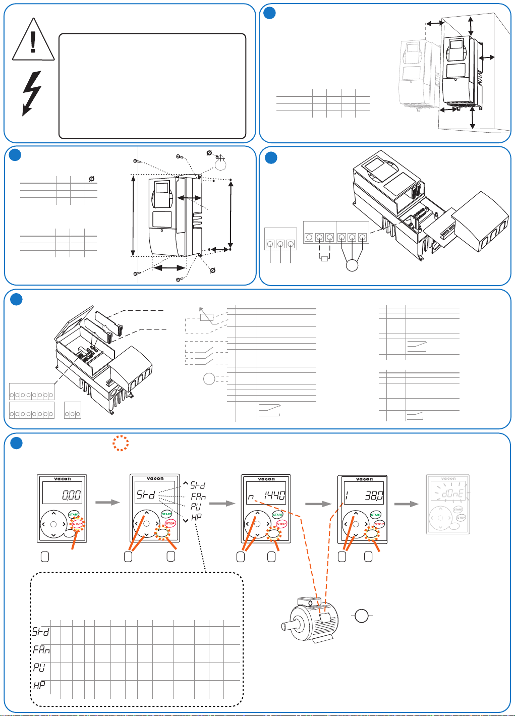
CAUTION
HIGH VOLTAGE!
VARAUSJÄNNITE!
HÖG SPÄNNING!
HOCHSPANNUNG!
HAUTE TENSION!
ALTA TENSIONE!
ALTA TENSIÓN!
Mounting dimensions (mm)
H2
W2
313
100
100
148
W1
128
144
195
D1
190
214
237
7
7
9
406
541
Unit dimensions (mm)
H1
327
419
558
SEE USER´S MANUAL CHAPTER 1
KATSO KÄYTTÖOHJE KOHTA 1
SE ANVÄNDARMANUALEN KAPITEL 1
SIEHE BETRIEBSANLEITUNG KAP. 1
VOIR MANUEL UTILISATEUR CHAP. 1
VEDI MANUALE BASE CAPITOLO 1
VER EL CAPITULO. 1 DEL MANUAL
H1
W1
D1
W2
H2
1
COOLING
A =Clearance around the unit
B =Distance from the unit to another unit
C =Free space above the unit
D =Free space underneath the unit
NXL
0003-0012 5
0016-0031 5
0038-0061 5
POWER
3
Dimensions (mm)
A
B
20
20
30
C
20
100
20
120
20
160
D
50
60
80
CONNECTIONS
Brake
resistor
U/T1V/T2 W/T3
M
L1 L2 L3
Mains
B- B+ R-
BB
C
A
A
D
4
CONTROL CONNECTIONS
9 10 11 18 19 A B 30
1 2 3 4 5 6 7 8
5
START-UP WIZARD
21 22 23
START
+
ENTER
-
reset
Push 5 seconds
1
to activate (in
stop mode)
I/O extension boards
Fieldbus boards
=Push the button
MODE
+
ENTER
-
reset
Select the
2
mode. See
table below!
3
+
-
Accept
1...10 kOhm
mA
CONTROL I/O standard
Terminal
1
2
3
4
5
6
7
8
9
10
11
18
19
A
B
30
21
22
23
Signal
10 Vref
Reference voltage
AI1+
Analog input, 0-10V
AI1-
Analog input common
AI2+
Analog input, 0/4-20 mA
AI2-
Analog input common
24 Vout
24 V auxiliary voltage
GND
I/O ground
Digital input 1 Start forward
DIN1
DIN2
Digital input 2 Start reverse
DIN3
Digital input 3 Preset speed 1
GND
I/O ground
AO1+
Analog output Output freq.
AO1-
Analog output common
RS 485
Serial bus (Modbus RTU)
RS 485
Serial bus
+24V
External control voltage supply
RO1
RO1
RO1
rpm
n
rpm
+
ENTER
-
reset
5
Accept
4
Tune
n(rpm)
Default
Relay output 1
FAULT
CONTROL I/O extension (optional)
Terminal Signal
1
+24V
2
GND
3
DIN1
4
OR
DIN2
5
DIN3
6
DO1
24
RO1
25
RO1
26
RO1
Terminal Signal
12
+24 V
13
GND
14
DIN1
15
DIN2
16
DIN3
28
TI1+
29
TI1-
2526RO1
RO1
OPT-AA
OPT-AI
In(A)
A
+
ENTER
-
reset
Accept
Tune
6
7
I(A)
Default
24 V auxiliary voltage
I/O ground
Digital input 1 Preset speed 2
Digital input 2 Fault reset
Digital input 3 Disable PID
Digital output Ready
Relay output 1
RUN
Default
24 V auxiliary voltage
I/O ground
Digital input 1 Preset speed 2
Digital input 2 Fault reset
Digital input 3 Disable PID
Thermistor input
Thermistor input
Relay output 1
RUN
DONE
+
ENTER
-
reset
3Acc time(s)
1.
P2.1.1Min.Freq(Hz)
P2.1..2 Max.Freq(Hz)
P2.
0Hz50Hz3s3sI *1,5 400V*50Hz0=
Standard
20Hz50Hz20s20sI *1,1 400 50Hz0=
Fan
20Hz50Hz5s5sI *1,1 400 50Hz0=
Pump
0Hz50Hz1s1sI *1,8 400 50Hz0=
High
performance
P2.1.4Dec time(s)
H
L
L
H
(V)*
0=
Ai1
0-10V
0=
Ai1
0-10V
0=
Ai1
0-10V
0=
Ai1
0-10V
21 Autorestart
1.
P2.1.14 I/0 ref
P2.
P3.1 Control place
0=
I/O
Not
used
0=
I/O
Not
used
0=
I/O
Not
used
0=
I/O
Not
used
*In drives of 208V...230V
this value is 230V
MM
NOTE! Startup Wizard returns
all other parameters to factory
defaults!
6Motor Un
1.
P2.1.5Currentlimit(A)
P2.
P2.1.7Motor fn(Hz)
P2.1.11Start funct.
P2.1.12 Stop funct.
P2.1.13 U/foptimization
V*
V*
V*
Ramp0=Coasting0=Not
Ramp0=Coasting0=Not
Ramp1=Ramp0=Not
Ramp0=Coasting
used
used
used
1=
automatic
torque
boost
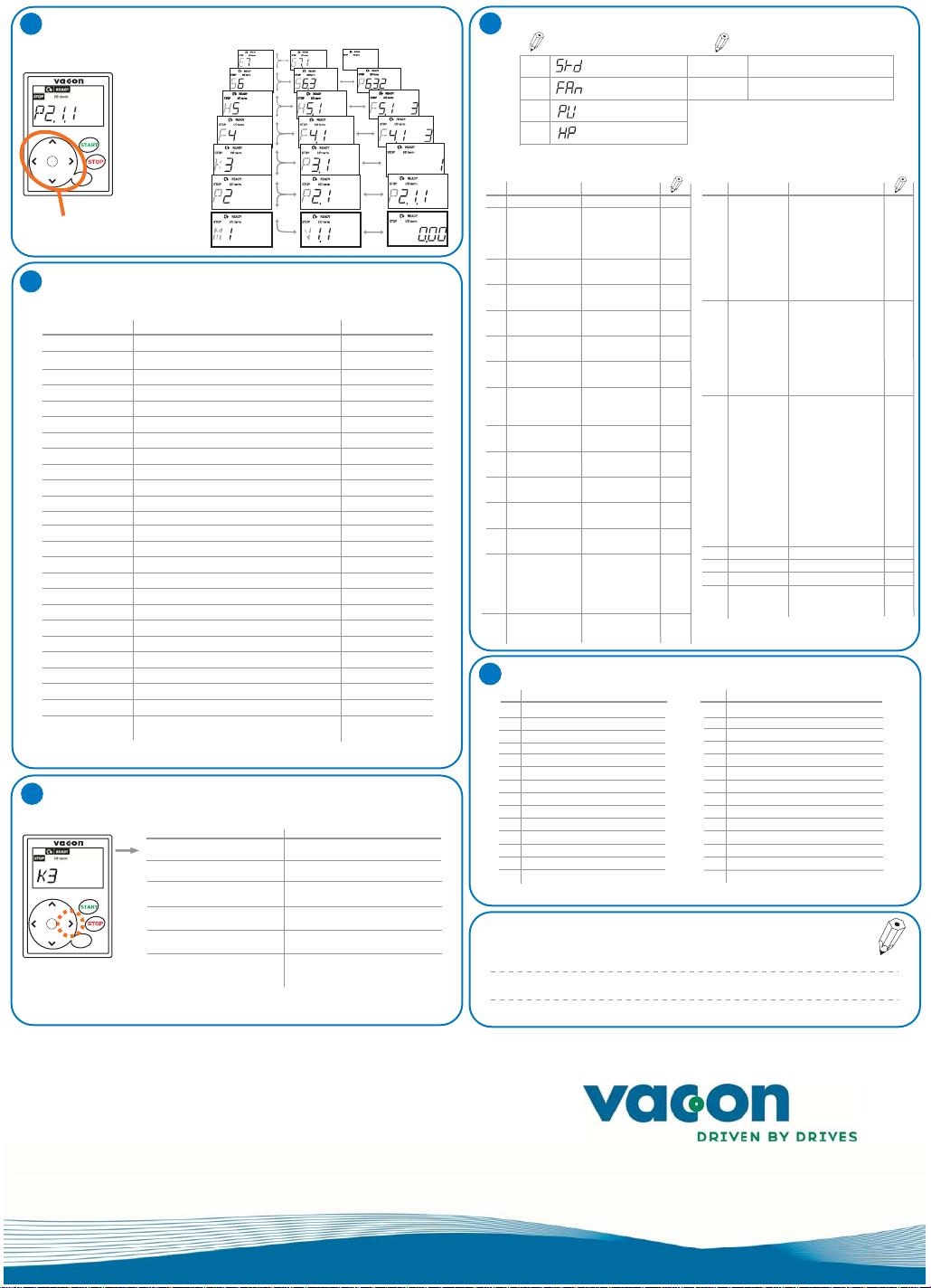
MENU STRUCTURE
6
Expander board menu
System menu
Fault history menu
+
ENTER
-
reset
Navigation and
selection keys
MONITORING MENU M1
7
Active faults menu
Keypad control menu
Parameter menu
Monitoring menu
Code Signal name Unit
V1.1 Output frequency Hz
V1.2 Frequency reference Hz
V1.3
V1.4
V1.5
V1.6
V1.7
V1.8
V1.9
V1.10
V1.11
V1.12
V1.13 Analogue output current 1, expander board mA
V1.14 Analogue output current 2, expander board mA
V1.15 DIN1, DIN2, DIN3
V1.16 DIE1, DIE2, DIE3
V1.17 RO1
V1.18 ROE1, ROE2, ROE3
V1.19
V1.20 PID Reference %
V1.21 PID Actual value %
V1.22 PID Error value %
V1.23 PID Output %
V1.24
V1.25
KEYPAD CONTROL MENU K3
8
+
ENTER
-
reset
Mode: 0= Not selected (default), 1= Standard,
2= Fan, 3= Pump, 4= High performance
P3.1 Selection of control place
R3.2 Keypad reference
P3.3 Keypad direction
P3.4 Stop button activation
P3.5 PID reference 1
P3.6 PID reference 2
Motor speed
Motor current
Motor torque %
Motor power
Motor voltage
DC-link voltage
Unit temperature
Analogue input 1
Analogue input 2
Analogue output current mA
DOE1
Autochange 1,2,3
Parameters
1= I/O Terminals, 2=Keypad, 3=Fieldbus
0= Forward, 1= Reverse
0= Limited function, 1= Always enabled
Selections
(Hz)
PARAMETER SETTINGS
9
SELECTED MODE MOTOR NAME PLATE VALUES
Standard mode
Fan mode
Pump mode
High performance mode
BASIC PARAMETERS
Parameter
Code
P 2.1.1 Min frequency
P 2.1.2 Max frequency
Acceleration time
P 2.1.3
P 2.1.4
P 2.1.5
P 2.1.6
rpm
P 2.1.7
A
%
V
V
ºC
P 2.1.8
P 2.1.9
P 2.1.10
P 2.1.11
P 2.1.12
P 2.1.13
P 2.1.14 I/O reference
P2.1.15 AI2 signal range
10
(%)
(%)
1
Deceleration time
1
Current
limit
Nominal voltage
of the motor
Nominal frequency
of the motor
Nominal speed
of the motor
Nominal current
of the motor
Motor cos
Start function
Stop function
U/f optimisation
FAULT CODES
CODE CODEFAULT FAULT
1 Overcurrent
2 Overvoltage
3 Earth fault
8 System fault
9 Undervoltage
11 Output phase supervision
13 Frequency converter undertemperature
14 Frequency converter overtemperature
15 Motor stalled
16 Motor overtemperature
17 Motor underload
22 EEPROM checksum fault
24 Counter fault
Microprocessor watchdog fault
25
Note
(Hz)
(Hz)
NOTE: If fmax > than the
motor synchronous speed,
check suitability for motor
and drive system
(s)
(s)
Output current limit (A)
of the unit
(V)
Check the rating plate
of the motor
(Hz)
Check the rating plate
of the motor
(rpm)
The default applies for a 4pole motor and a nominal
size frequency converter.
(A)
Check the rating plate
of the motor
Check the rating plate
of the motor
0=Ramp
1=Flying start
0=Coasting
1=Ramp
0=Not used
1=Automatic torque boost
0=AI1
1=AI2
2=Keypad reference
3=Fieldbus reference
(FBSpeedReference)
4=Motor potentiometer
5=AI1/AI2 selection
1=0mA - 20mA
2=4mA - 20mA
3=0V - 10V
4=2V - 10V
Code
P2.1.16
P2.1.17 DIN2 function
P2.1.18 DIN3 function
P2.1.19 Preset speed 1
P2.1.20 Preset speed 2
P2.1.21
P2.1.22 Parameter
P 2.1.8 Nominal motor speed
P 2.1.9 Nominal motor current
Parameter
Analogue
output function
Autom. restart
conceal
29
34 Internal bus communication
35 Application fault
39 Device removed
40 Device unknown
41 IGBT temperature
44 Device change
45 Device added
50 Analogue input
51 External fault
52 Keypad communication fault
53 Fieldbus fault
54 Slot fault
55 Actual value supervision
Thermistor fault
Note
0=Not used
1=Output freq. (0-fmax)
2=Freq. reference (0-fmax)
3=Motor speed (0-Mot.nom. spd)
4=Output current (0-InMotor)
5=Motor torque (0-TnMotor
6=Motor voltage (0-UnMotor)
7=DC-link volt (0-1000V)
8=PI controller ref. value
9=PI contr. act. value 1
10=PI contr. error value
11=PI controller output
0=Not used
1=Start Reverse
2=Reverse
3=Stop pulse
4=External fault, cc
5=External fault, oc
6=Run enable
7=Preset speed 2
8= Motor pot. UP (cc)
9= Disable PID (Direct freq. ref.)
10=Interlock 1
0=Not used
1=Reverse
2=External fault, cc
3=External fault, oc
4=Fault reset
5=Run enable
6=Preset speed 1
7=Preset speed 2
8=DC-braking command
9=Motor pot. UP (cc)
10=Motor pot. DOWN (cc)
11=Disable PID (PID ctrl selection)
12=PID Keypad ref. 2 selection
13=Interlock 2
14=Thermistor input (See Ch. 6.2.4)
15=Force control place to I/O
16=Force ctrl place to fieldbus
17=AI1/AI2 selection
(Hz)
(Hz)
0=Not used 1=Used
0=All parameters and
menus visible
1=P2.1 and menus
MI - H5 visible
Iin < 4mA (sel. signal range 4to20 mA)
)
www.vacon.com
ud01074
vacon nxl
quick guide
 Loading...