

Page 1
Application Guide
VACON® NX All-in-One
drives.danfoss.com
Page 2

Page 3

VACON® NX All-in-One
Application Guide
Contents
1
Introduction 8
1.1
Purpose of this Application Guide 8
Manual and Software Version 8
1.2
Additional Resources 8
1.3
1.4
Parameter Table Reading Guide 8
2
Basic Application 10
2.1
Introduction to Basic Application 10
2.1.1
Motor Protection Functions in the Basic Application 10
2.2
Control I/O in Basic Application 11
2.3
Control Signal Logic in Basic Application 12
2.4
Parameter Lists for Basic Application 12
2.4.1
Monitoring Values (Control Panel: Menu M1) 12
Contents
2.4.2
Basic Parameters (Control Panel: Menu M2 -> G2.1) 13
2.4.3
Keypad Control (Control Panel: Menu M3) 15
2.4.4
System Menu (Control Panel: Menu M6) 15
2.4.5
Expander Boards (Control Panel: Menu M7) 15
3
Standard Application 16
3.1
Introduction to Standard Application 16
3.2
Control I/O in Standard Application 17
3.3
Control Signal Logic in Standard Application 18
3.4
Parameter Lists for Standard Application 18
3.4.1
Monitoring Values (Control Panel: Menu M1) 12
3.4.2
Basic Parameters (Control Panel: Menu M2 -> G2.1) 19
3.4.3
Input Signals (Control Panel: Menu M2 -> G2.2) 20
3.4.4
Output Signals (Control Panel: Menu M2 ->G2.3) 21
3.4.5
Drive Control Parameters (Control Panel: Menu M2->G2.4) 23
3.4.6
Prohibit Frequency Parameters (Control Panel: Menu M2 -> G2.5) 23
3.4.7
Motor Control Parameters (Control Panel: Menu M2 -> G2.6) 24
3.4.8
Protections (Control Panel: Menu M2 -> G2.7) 25
3.4.9
Autorestart Parameters (Control Panel: Menu M2 -> G2.8) 27
3.4.10
Keypad Control (Control Panel: Menu M3) 27
3.4.11
System Menu (Control Panel: Menu M6) 15
3.4.12
Expander Boards (Control Panel: Menu M7) 15
4
Local/Remote Control Application 28
4.1
Introduction to Local/Remote Control Application 28
AB296635287482en-000201/DPD00903 | 3Danfoss A/S © 2020.12
Page 4

VACON® NX All-in-One
Application Guide
4.2
Control I/O in Local/Remote Control Application 29
4.3
Control Signal Logic in Local/Remote Control Application 31
4.4
Parameter Lists for Local/Remote Control Application 31
4.4.1
Monitoring Values (Control Panel: Menu M1) 12
4.4.2
Basic Parameters (Control Panel: Menu M2 -> G2.1 32
4.4.3
Input Signals (Control Panel: Menu M2 -> G2.2) 33
4.4.4
Output Signals (Control Panel: Menu M2 -> G2.3) 36
4.4.5
Drive Control Parameters (Control Panel: Menu M2->G2.4) 23
4.4.6
Prohibit Frequency Parameters (Control Panel: Menu M2 -> G2.5) 39
4.4.7
Motor Control Parameters (Control Panel: Menu M2 -> G2.6) 24
4.4.8
Protections (Control Panel: Menu M2 -> G2.7) 25
4.4.9
Autorestart Parameters (Control Panel: Menu M2 -> G2.8) 27
4.4.10
Keypad Control (Control Panel: Menu M3) 27
4.4.11
System Menu (Control Panel: Menu M6) 15
Contents
4.4.12
Expander Boards (Control Panel: Menu M7) 15
5
Multi-step Speed Control Application 44
5.1
Introduction to Multi-step Speed Control Application 44
5.2
Control I/O in Multi-step Speed Control 45
5.3
Control Signal Logic in Multi-step Speed Control Application 46
5.4
Parameter Lists for Multi-step Speed Control Application 47
5.4.1
Monitoring Values (Control Panel: Menu M1) 12
5.4.2
Basic Parameters (Control Panel: Menu M2 -> G2.1) 47
5.4.3
Input Signals (Control Panel: Menu M2 -> G2.2) 49
5.4.4
Output Signals (Control Panel: Menu M2 -> G2.3) 51
5.4.5
Drive Control Parameters (Control Panel: Menu M2->G2.4) 23
5.4.6
Prohibit Frequency Parameters (Control Panel: Menu M2 -> G2.5) 39
5.4.7
Motor Control Parameters (Control Panel: Menu M2 -> G2.6) 24
5.4.8
Protections (Control Panel: Menu M2 -> G2.7) 56
5.4.9
Autorestart Parameters (Control Panel: Menu M2 -> G2.8) 27
5.4.10
Keypad Control (Control Panel: Menu M3) 27
5.4.11
System Menu (Control Panel: Menu M6) 15
5.4.12
Expander Boards (Control Panel: Menu M7) 15
6
PID Control Application 59
6.1
Introduction to PID Control Application 59
6.2
Control I/O in PID Control Application 60
6.3
Control Signal Logic in PID Control Application 62
6.4
Parameter Lists for PID Control Application 62
AB296635287482en-000201/DPD009034 | Danfoss A/S © 2020.12
Page 5

VACON® NX All-in-One
Application Guide
6.4.1
Monitoring Values (Control Panel: Menu M1) 62
6.4.2
Basic Parameters (Keypad Panel: Menu M2 -> G2.1) 63
6.4.3
Input Signals (Control Panel: Menu M2 -> G2.2) 65
6.4.4
Output Signals (Control Panel: Menu M2 -> G2.3) 68
6.4.5
Drive Control Parameters (Control Panel: Menu M2 -> G2.4) 70
6.4.6
Prohibit Frequency Parameters (Control Panel: Menu M2 -> G2.5) 71
6.4.7
Motor Control Parameters (Control Panel: Menu M2 -> G2.6) 72
6.4.8
Protections (Control Panel: Menu M2 -> G2.7) 73
6.4.9
Autorestart Parameters (Control Panel: Menu M2 -> G2.8) 27
6.4.10
Keypad Control (Control Panel: Menu M3) 75
6.4.11
System Menu (Control Panel: Menu M6) 15
6.4.12
Expander Boards (Control Panel: Menu M7) 15
7
Multi-purpose Control Application 77
7.1
Introduction to Multi-purpose Control Application 77
Contents
7.2
Control I/O in Multi-purpose Control Application 78
7.3
Control Signal Logic in Multi-purpose Control Application 79
7.4
Parameter Lists for Multi-purpose Control Application 79
7.4.1
Monitoring Values (Control Panel: Menu M1) 79
7.4.2
Basic Parameters (Control Panel: Menu M2 -> G2.1) 90
7.4.3
Input Signals 92
7.4.4
Output Signals 97
7.4.5
Drive Control Parameters (Control Panel: Menu M2 -> G2.4) 102
7.4.6
Prohibit Frequency Parameters (Control Panel: Menu M2 -> G2.5) 71
7.4.7
Motor Control Parameters, VACON® NXS (Control Panel: Menu M2 -> G2.6) 104
7.4.8
Motor Control Parameters, VACON® NXP (Control Panel: Menu M2 -> G2.6) 107
7.4.9
Protections (Control Panel: Menu M2 -> G2.7) 111
7.4.10
Autorestart Parameters (Control Panel: Menu M2 -> G2.8) 27
7.4.11
Fieldbus Parameters (Control Panel: Menu M2 -> G2.9) 117
7.4.12
Torque Control Parameters (Control Panel: Menu M2 -> G2.10) 118
7.4.13
Master Follower Parameters, VACON® NXP (Control Panel: Menu M2 -> G2.11 119
7.4.14
Functional Safety (Control Panel: Menu M2 -> G.12) 120
7.4.15
Condition-based Monitoring (Control Panel: Menu M2 -> G.13) 121
7.4.16
Keypad Control (Control Panel: Menu M3) 125
7.4.17
System Menu (Control Panel: Menu M6) 15
7.4.18
Expander Boards (Control Panel: Menu M7) 15
8
Pump and Fan Control Application 127
8.1
Introduction to Pump and Fan Control Application 127
AB296635287482en-000201/DPD00903 | 5Danfoss A/S © 2020.12
Page 6

VACON® NX All-in-One
Application Guide
8.2
Control I/O in Pump and Fan Control Application 128
8.3
Control Signal Logic in Pump and Fan Control Application 131
8.4
Parameter Lists for Pump and Fan Control Application 131
8.4.1
Monitoring Values (Control Panel: Menu M1) 131
8.4.2
Basic Parameters (Control Panel: Menu M2 -> G2.1) 132
8.4.3
Input Signals 134
8.4.4
Output Signals 138
8.4.5
Drive Control Parameters (Control Panel: Menu M2 -> G2.4) 142
8.4.6
Prohibit Frequency Parameters (Control Panel: Menu M2 -> G2.5) 71
8.4.7
Motor Control Parameters (Control Panel: Menu M2 ->G2.6) 143
8.4.8
Protections (Control Panel: Menu M2 -> G2.7) 144
8.4.9
Auto Restart Parameters (Control Panel: Menu M2 -> G2.8) 146
8.4.10
Pump and Fan Control Parameters (Control Panel: Menu M2 -> G2.9) 146
8.4.11
Keypad Control (Control Panel: Menu M3) 148
Contents
8.4.12
System Menu (Control Panel: Menu M6) 15
8.4.13
Expander Boards (Control Panel: Menu M7) 15
9
Monitoring Value Descriptions 149
10
Parameter Descriptions 165
10.611
Keypad Control Parameters 298
10.612
Master/Follower Function 299
10.613
External Brake Control with Additional Limits (IDs 315, 316, 346–349, 352, 353) 300
10.614
Parameters of Motor Thermal Protection (IDs 704–708) 302
10.615
Parameters of Stall Protection (IDs 709–712) 303
10.616
Parameters of Underload Protection (IDs 713–716) 303
10.617
Fieldbus Control Parameters (IDs 850–859) 303
10.617.1
Process Data Out (Slave -> Master) 303
10.617.2
Current Scaling in Different Size of Units 303
10.617.3
Process Data in (Master -> Slave) 304
10.618
Closed Loop Parameters (IDs 612–621) 305
10.619
"Terminal to Function" (TTF) Programming Principle 305
10.619.1
Defining an Input/Output for a Certain Function on Keypad 305
10.619.2
Defining a Terminal for a Certain Function with VACON® NCDrive 306
10.619.3
Defining Unused Inputs/Outputs 307
10.620
Speed Control Parameters (Multi-Purpose Control Application Only) 307
10.621
Functional Safety Parameters (Multi-Purpose Control Application Only) 309
10.622
Automatic Changing Between Drives (Pump and Fan Control Application Only) 310
10.623
Interlock Selection (Pump and Fan Control Application Only) 310
AB296635287482en-000201/DPD009036 | Danfoss A/S © 2020.12
Page 7

VACON® NX All-in-One
Application Guide
10.624
Examples of Autochange and Interlock Selection 310
10.624.1
Pump and Fan Automatics with Interlocks and No Autochange 310
10.624.2
Pump and Fan Automatics with Interlocks and Autochange 311
10.625
Fieldbus Control in Detail 314
10.625.1
Combination 2: Bypass - ProfiDrive 314
10.625.2
Combination 3: Bypass - Standard 316
10.626
Condition-based Monitoring 317
10.626.1
Stages of Condition-based Monitoring 318
11
Fault Tracing 320
11.1
Faults and Alarms 320
Contents
AB296635287482en-000201/DPD00903 | 7Danfoss A/S © 2020.12
Page 8
•
•
•
•
•
•
•
•
•
-
-
•
Manual Edition
Remarks
Software code
DPD00903H
New and updated monitoring values
and parameters in Multi-purpose Control Application, for example, related to
Condition-based Monitoring.
New faults related to Condition-based
Monitoring
Other minor changes and corrections
throughout the manual.
Basic Application = ASFIFF01, Version 4.08
Standard Application = ASFIFF02, Version 4.08
Local/Remote Control Application = ASFIFF03, Version 4.08
Multi-step Speed Control Application = ASFIFF04, Version 4.08
PID Control Application = ASFIFF05, Version 4.11
Multi-purpose Control Application
VACON® NXS = ASFIFF06, Version 4.14
VACON® NXP = APFIFF06, Version 2.64
Pump and Fan Control Application = ASFIFF07, Version 4.09
NOTE! Download the English and French product manuals with applicable safety, warning and caution information from https://
www.danfoss.com/en/service-and-support/.
REMARQUE Vous pouvez télécharger les versions anglaise et française des manuels produit contenant l'ensemble des informations de sécurité, avertissements et mises en garde applicables sur le site https://www.danfoss.com/en/service-and-support/.
Index
Min Max Unit Default
ID Description
Parameter
e30bg858.10
A
B
C
D E F G H
VACON® NX All-in-One
Application Guide
Introduction
1 Introduction
1.1 Purpose of this Application Guide
This Application Guide provides information on functions of different applications, available parameters, and alarms to help in configuring the system, programming, and troubleshooting the AC drive. It is intended for use by qualified personnel. Read and follow
the instructions to use the drive safely and professionally. Pay particular attention to the safety instructions and general warnings
that are provided in this manual and other documentation delivered with the drive.
1.2 Manual and Software Version
This manual is regularly reviewed and updated. All suggestions for improvement are welcome.
The original language of this manual is English.
Table 1: Manual and Software Version
1.3 Additional Resources
Other resources are available to understand advanced AC drive functions and operation.
•
VACON® NXS/NXP Air-cooled Wall-mounted and Standalone Operating Guide
•
VACON® NXP NXC User Manual
VACON® NXP IP00 User Manual
•
VACON® NXP Liquid Cooled User Manual
•
Instructions for operation with option boards and other optional equipment.
•
Supplementary publications and manuals are available from Danfoss.
For US and Canada market:
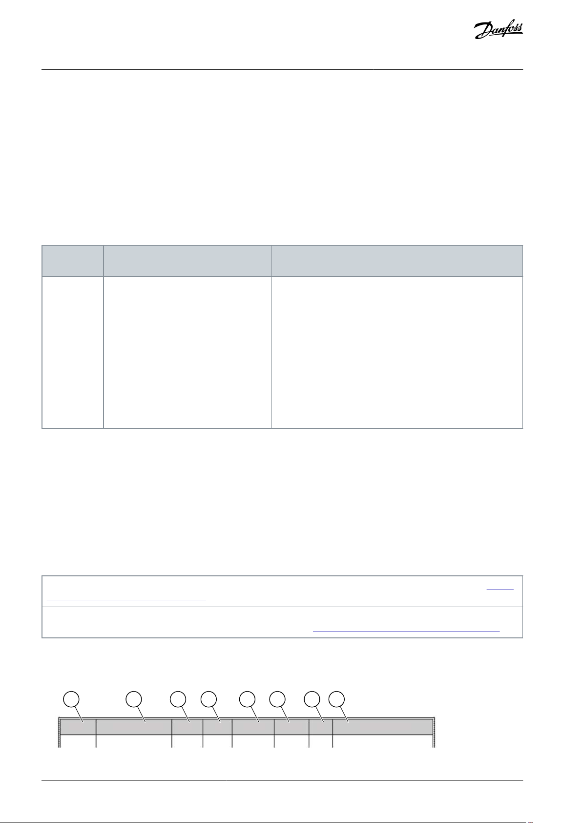
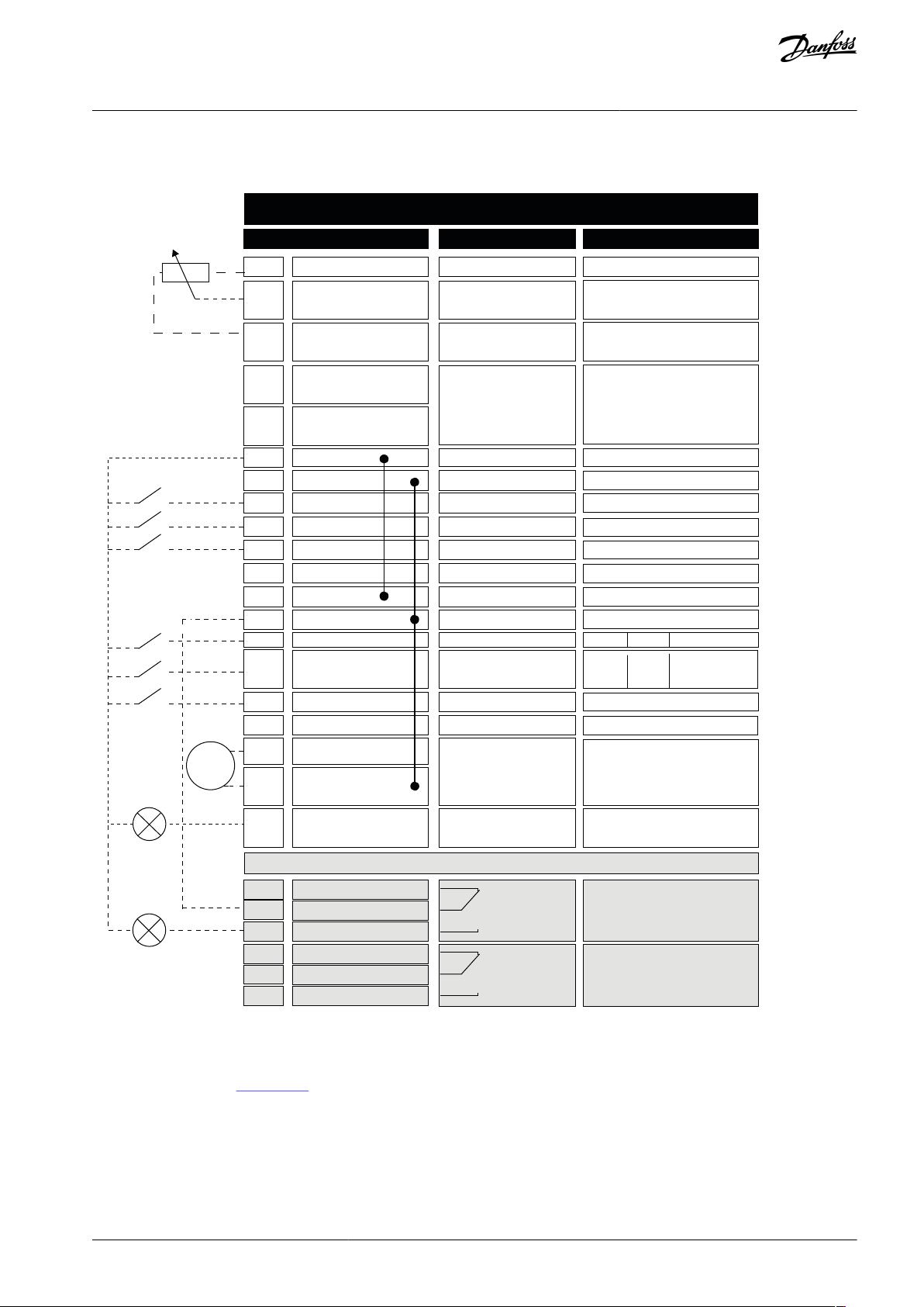
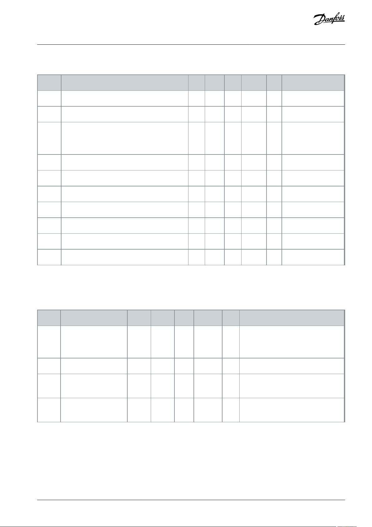
1.4 Parameter Table Reading Guide
This manual includes a large quantity of parameter tables. These instructions tell you how to read the tables.
Illustration 1: Parameter Table Reading Guide
AB296635287482en-000201 / DPD009038 | Danfoss A/S © 2020.12
Page 9

A
The location of the parameter in the menu, that is,
the parameter number.
B
The name of the parameter.
C
The minimum value of the parameter.
D
The maximum value of the parameter.
E
The unit of the value of the parameter. The unit
shows if it is available.
F
The value that was set in the factory.
G
The ID number of the parameter.
H
A short description of the values of the parameter
and/or its function.
VACON® NX All-in-One
Application Guide
Introduction
AB296635287482en-000201 / DPD00903 | 9Danfoss A/S © 2020.12
Page 10

VACON® NX All-in-One
Application Guide
Basic Application
2 Basic Application
2.1 Introduction to Basic Application
The Basic Application is a simple and easy-to-use application. It is the default setting on delivery from the factory. Otherwise select
the Basic Application in menu M6 on page S6.2. See the User Manual of the product.
Digital input DIN 3 is programmable.
The parameters of the Basic Application are explained in Chapter Parameter descriptions of this manual. The explanations are ar-
ranged according to the individual ID number of the parameter.
2.1.1 Motor Protection Functions in the Basic Application
The Basic Application provides almost all the same protection functions as the other applications:
•
External fault protection
•
Input phase supervision
•
Undervoltage protection
•
Output phase supervision
•
Earth fault protection
•
Motor thermal protection
•
Thermistor fault protection
•
Fieldbus fault protection
•
Slot fault protection
Unlike the other applications, the Basic Application does not provide any parameters for choosing the response function or limit
values for the faults. For more information on the motor thermal protection, see 10.336 (ID 704) Motor Thermal Protection and
10.614 Parameters of Motor Thermal Protection (IDs 704–708).
AB296635287482en-000201 / DPD0090310 | Danfoss A/S © 2020.12
Page 11
1
6
2
3
4
5
18
19
20
12
7
13
8
9
10
14
15
16
21
OPTA 2 / OPTA 3
22
23
11
17
24
25
26
DIN4
DIN5
Voltage for
potentiometer, etc.
Ground for reference
and controls
Ground for reference
and controls
Ground for reference
and controls
Analogue input 2
frequency reference
Voltage for switches (see #6)
Connect to GND or +24 V
FAULT
External fault input
Programmable (P2.17)
Connect to
GND or +24 V
Contact open = no action
Contact closed = fault reset
Contact open = no fault
Contact closed = fault
Contact closed = start forward
Contact closed = start reverse
Analogue output 1
Output frequency
Programmable
(P2.16)
Range 0—20 mA/RL,
max. 500 Ω
Open collector,
I≤50 mA, U≤48 VDC
Digital output 1
READY
RUN
mA
READY
AO1-
DO1
+24V
GND
GND
DIN1
DIN2
DIN3
DIN4
DIN5
DIN6
R O1
R O1
R O1
CMA
CMB
R O2
R O2
R O2
Standard I/O board
Terminal Signal Description
+10V
ref
AI1+
AI1-
AI2+
AI2-
+24V
Reference output
Analogue input 1
Voltage range 0—10 V DC
Programmable (P2.14)
Analogue input 2
Current range 0-20mA
Control voltage output
I/O ground
I/O ground
Preset speed select 1
Preset speed select 2
Fault reset
Common for DIN 1—DIN 3
Common for DIN4-DIN6
Control voltge output
I/O ground
Relay output 1
Relay output 2
AO1+
Analogue input 1
frequency reference
Voltage for switches,
etc. max 0.1 A
Start forward
Start reverse
Freq. ref.
Open
Closed
Open
Closed
Open
Open
Closed
Closed
I/O ref (P2.14)
Preset Speed 1
Preset Speed 2
Max frequency
RUN
Reference potentiometer,
1-10kΩ
e30bh055.20
VACON® NX All-in-One
Application Guide
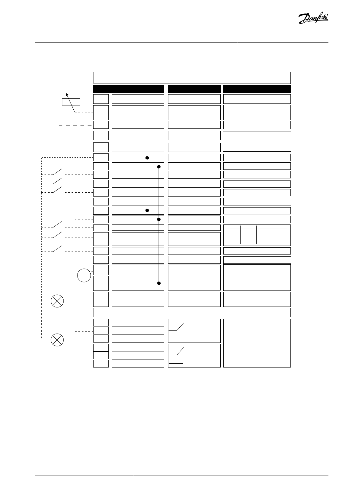
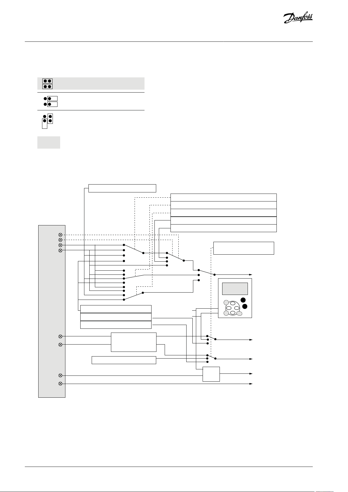
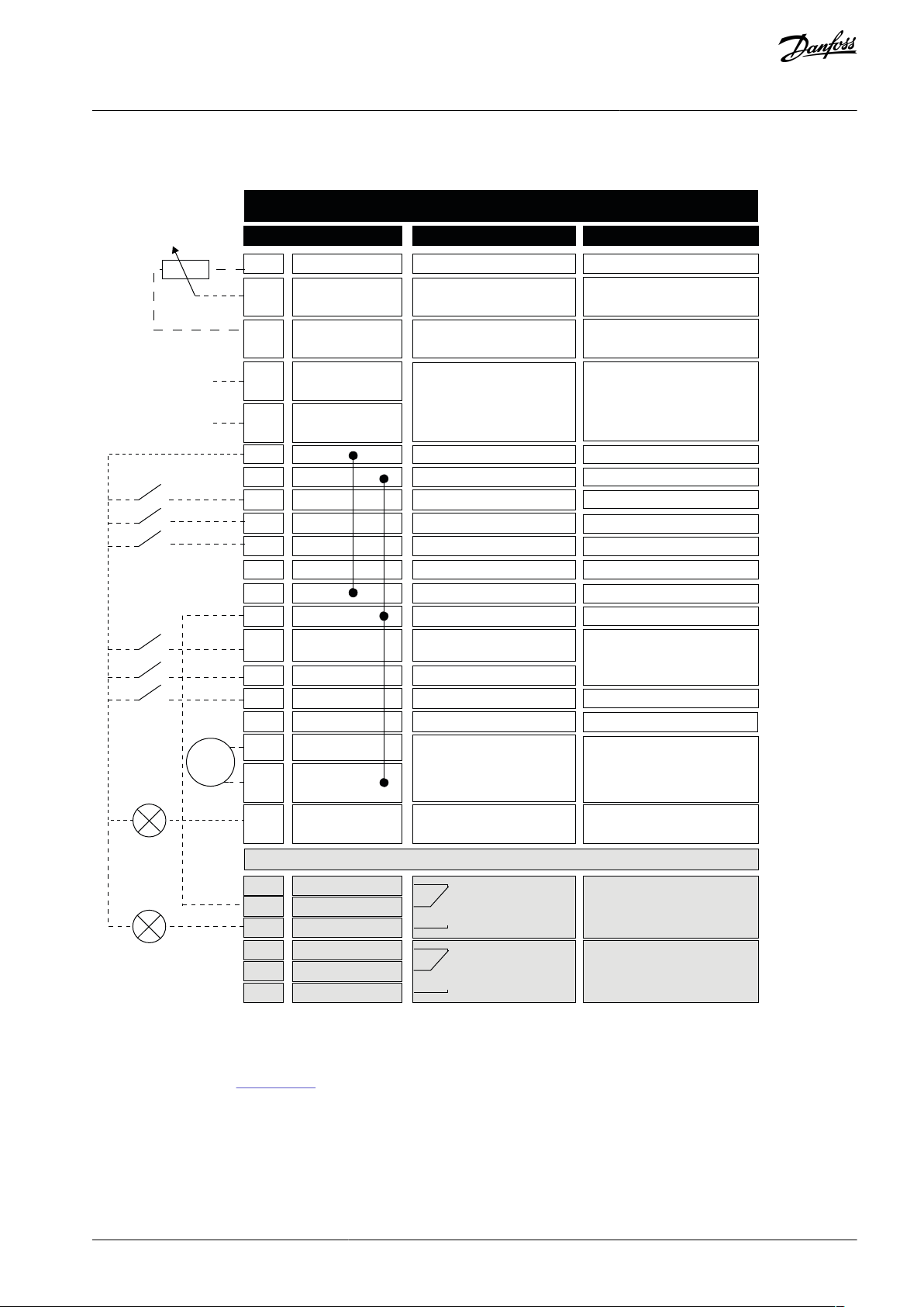
2.2 Control I/O in Basic Application
Illustration 2: Default I/O Configuration in Basic Application
The option board OPTA3 has no terminal for open contact on its second relay output (terminal 24 is missing).
See jumper selections in Illustration 3. More information in the User Manual of the product.
AB296635287482en-000201 / DPD00903 | 11Danfoss A/S © 2020.12
Basic Application
Page 12
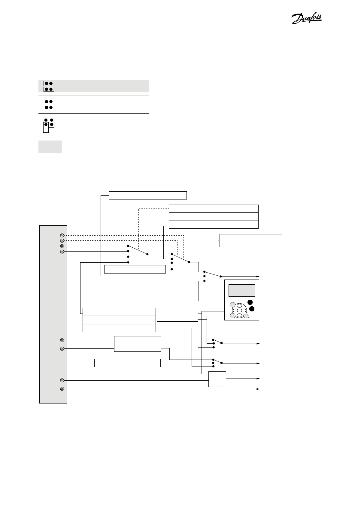
Jumper block X3:
CMA and CMB grounding
CMB connected to GND
CMA connected to GND
CMB isolated from GND
CMA isolated from GND
CMB and CMA internally
connected together,isolated
from GND
= Factory default
e30bh013.10
e30bh049.10
DIN4
DIN5
AI1
AI2
DIN1
DIN2
DIN6
DIN3
≥ 1
3.2 Keypad reference
3.1 Control place
Start forward
Start reverse
Start/Stop
Reverse
Internal Start/Stop
Internal reverse
Internal fault reset
Fault reset input
External fault input (programmable)
Reset button
Start/Stop buttons
Reference from fieldbus
Start/Stop from fieldbus
Direction from fieldbus
3.3 Keypad direction
2.14 I/O Reference
2.19 Preset Speed 2
2.18 Preset Speed 1
2.2 Max Frequency
Start/Stop and
reverse logic
Internal frequency
reference
VACON® NX All-in-One
Application Guide
Illustration 3: Jumper Selections
2.3 Control Signal Logic in Basic Application
Basic Application
Illustration 4: Control Signal Logic of the Basic Application
2.4 Parameter Lists for Basic Application
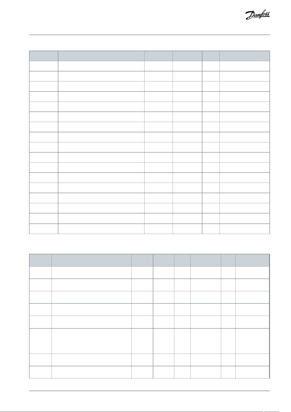
2.4.1 Monitoring Values (Control Panel: Menu M1)
The monitoring values are the actual values of parameters and signals as well as statuses and measurements. Monitoring values
cannot be edited.
AB296635287482en-000201 / DPD0090312 | Danfoss A/S © 2020.12
Page 13
Index
Monitoring value
Unit
Form
ID
Description
V1.1
Output frequency
Hz
#.##1-
V1.2
Frequency reference
Hz
#.##25-
V1.3
Motor speed
RPM#2-V1.4
Motor current
A
Varies
3-V1.5
Motor torque
%
#.#4-
V1.6
Motor shaft power
%
#.#5-
V1.7
Motor voltage
V
#.#6-
V1.8
DC-link voltage
V#7-V1.9
Unit temperature
°C#8-V1.10
Motor temperature
%
#.#9-
V1.11
Analog input 1
V/mA
#.##13-
V1.12
Analog input 2
V/mA
#.##14-
V1.13
DIN 1, 2, 3
--15-V1.14
DIN 4, 5, 6
--16-V1.15
DO1, RO1, RO2
--17
-
V1.16
Analog I
out
mA
#.##26-
V1.17
Multimonitoring items
---
-
Index
Parameter
Min
Max
Unit
Default
ID
Description
P2.1
Min frequency
0.00
P2.2Hz0.00
101-P2.2
Max frequency
P2.1
320.00
Hz
50.00
102-P2.3
Acceleration time 1
0.1
3000.0
s
3.0
103-P2.4
Deceleration time 1
0.1
3000.0
s
3.0
104
-
P2.5
Current limit
0.1 x I
H
2 x IHA
IL107
-
P2.6
Nominal voltage of the motor
180
690VNX2: 230 V
NX5: 400 V
NX6: 690 V
110
-
P2.7
Nominal frequency of the motor
8.00
320.00
Hz
50.00
111
P2.8
Nominal speed of the motor
24
20 000
RPM
1440
112
-
VACON® NX All-in-One
Application Guide
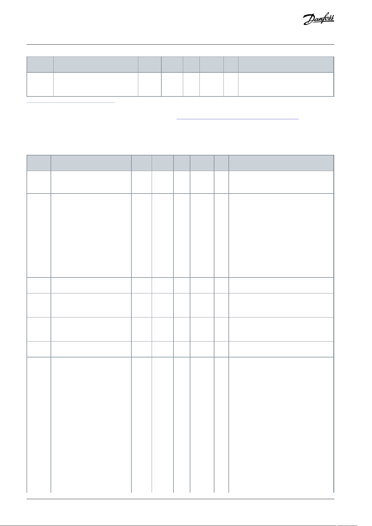
Table 2: Monitoring Values
Basic Application
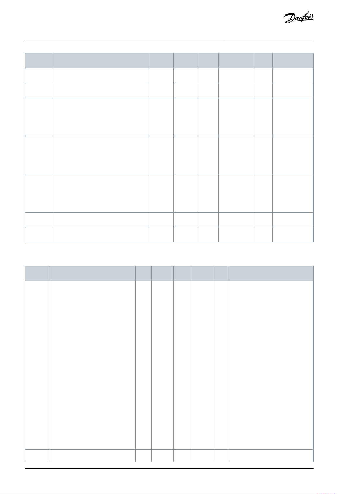
2.4.2 Basic Parameters (Control Panel: Menu M2 -> G2.1)
Table 3: Basic Parameters G2.1
AB296635287482en-000201 / DPD00903 | 13Danfoss A/S © 2020.12
Page 14
Index
Parameter
Min
Max
Unit
Default
ID
Description
P2.9
Nominal current of the motor
0.1 x I
H
2 X IHA
IH113
-
P2.10
Motor cos phi
0.30
1.00-0.85
120
-
P2.11
Start function
0
2-0
505
0 = Ramp
1 = Flying start
2 = Conditional flying start
P2.12
Stop function
0
3-0
506
0 = Coasting
1 = Ramp
2 = Ramp + Run enable coast Ramp
3 = Coast + Run enable ramp
P2.13
U/f optimization
0
1-0
109
0 = Not used
1 = Automatic torque boost
P2.14
I/O reference
0
3-0
117
0 = AI1
1 = AI2
2 = Keypad
3 = Fieldbus
P2.15
Analog input 2, reference offset
0
1-1
302
0 = 0–20 mA
1 = 4–20 mA
P2.16
Analog output function
0
8-1
307
0 = Not used
1 = Output freq. (0- f
max
)
2 = Freq. reference (0-f
max
)
3 = Motor speed (0-Motor nominal speed)
4 = Output current (0-InMotor)
5 = Motor torque (0-TnMotor)
6 = Motor power (0-PnMotor)
7 = Motor voltage (0-UnMotor)
8 = DC-link volt (0-1000V)
P2.17
DIN 3 function
0
7-1
301
0 = Not used
1 = Ext. fault, closing cont.
2 = Ext. fault, opening cont.
3 = Run enable, cc
4 = Run enable, oc
5 = Force cp. to I/O
6 = Force cp. to keypad
7 = Force cp. to fieldbus
P2.18
Preset speed 1
0.00
P2.2Hz0.00
105-P2.19
Preset speed 2
0.00
P2.2Hz50.00
106
-
P2.20
Automatic restart
0
1-0
731
0 = Disabled
2 = Enabled
VACON® NX All-in-One
Application Guide
Basic Application
AB296635287482en-000201 / DPD0090314 | Danfoss A/S © 2020.12
Page 15
Index
Parameter
Min
Max
Unit
Default
ID
Description
P3.1
Control place
1
3-1
125
1 = I/0 terminal
2 = Keypad
3 = Fieldbus
P3.2
Keypad reference
P2.1
P2.2Hz0.00
-
-
P3.3
Direction (on keypad)
0
1-0
123
0 = Forward
1 = Reverse
R3.4
Stop button
0
1-1
114
0 = Limited function of Stop button
1 = Stop button always enabled
VACON® NX All-in-One
Application Guide
Basic Application
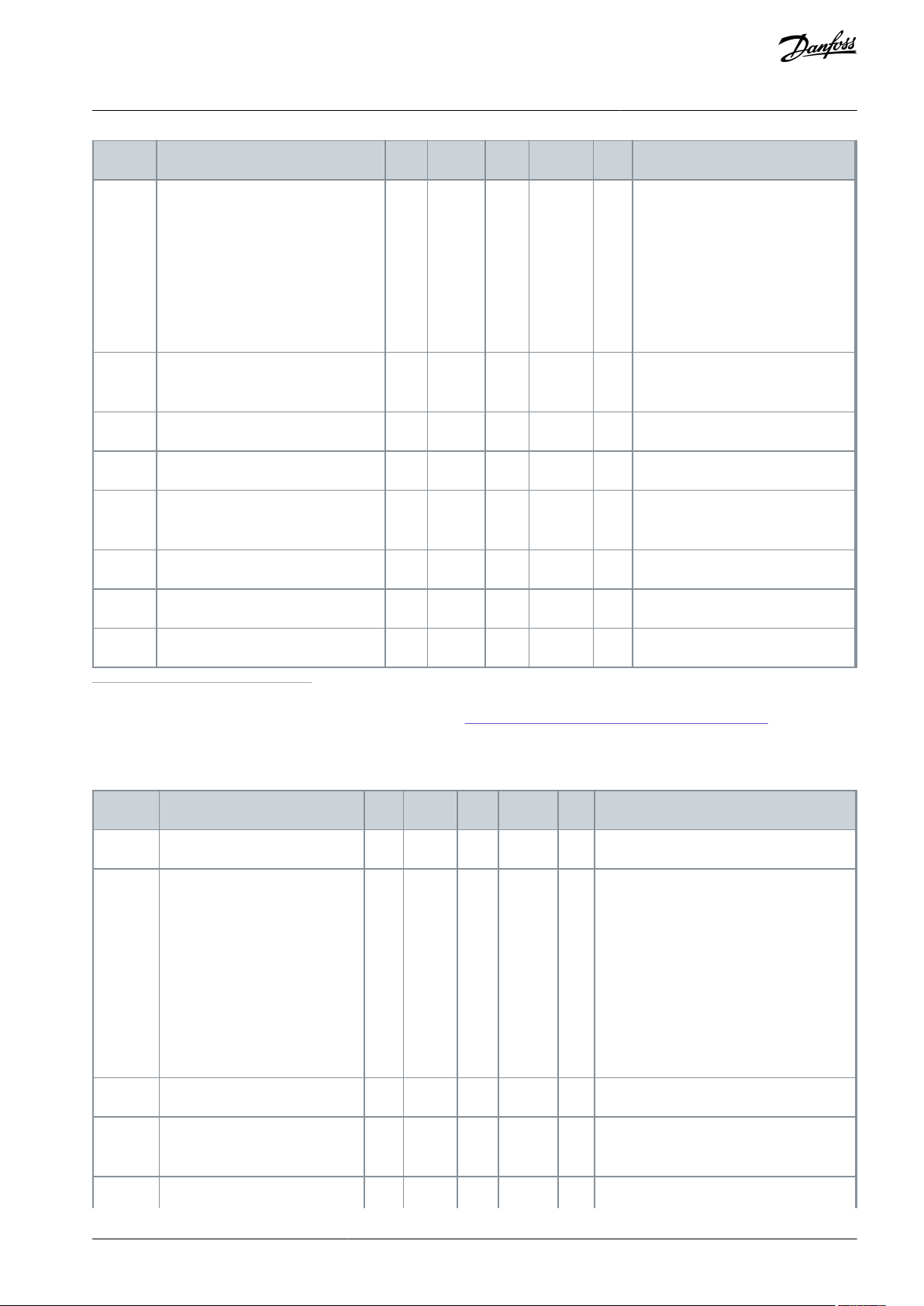
2.4.3 Keypad Control (Control Panel: Menu M3)
The parameters for the selection of control place and direction on the keypad are listed in Table 4. See the Keypad control menu in
the User Manual of the product.
Table 4: Keypad Control Parameters, M3
2.4.4 System Menu (Control Panel: Menu M6)
For more information related to the general use of the AC drive, such as selecting application and language, customized parameter
sets, or hardware and software, see the User Manual of the product.
2.4.5 Expander Boards (Control Panel: Menu M7)
The M7 menu shows the expander and option boards attached to the control board and board-related information. For more information, see the User Manual of the product.
AB296635287482en-000201 / DPD00903 | 15Danfoss A/S © 2020.12
Page 16

VACON® NX All-in-One
Application Guide
Standard Application
3 Standard Application
3.1 Introduction to Standard Application
Select the Standard Application in menu M6 on page S6.2.
The Standard Application is typically used in pump and fan applications and conveyors for which the Basic Application is too limited
but where no special features are needed.
•
The Standard Application has the same I/O signals and the same control logic as the Basic Application.
•
Digital input DIN 3 and all the outputs are freely programmable.
Extra functions:
•
Programmable Start/Stop and Reverse signal logic
•
Reference scaling
•
One frequency limit supervision
•
Second ramps and S-shape ramp programming
•
Programmable start and stop functions
•
DC brake at stop
•
One prohibit frequency area
•
Programmable U/f curve and switching frequency
•
Auto restart
•
Motor thermal and stall protection: Programmable action; off, warning, fault
The parameters of the Standard Application are explained in Chapter Parameter descriptions of this manual. The explanations are
arranged according to the individual ID number of the parameter.
AB296635287482en-000201 / DPD0090316 | Danfoss A/S © 2020.12
Page 17
1
6
2
3
4
5
18
19
20
12
7
13
8
9
10
14
15
16
21
22
23
11
17
24
25
26
DIN4
DIN5
mA
READY
RUN
AO1-
DO1
+24 V
GND
GND
DIN1
DIN2
DIN3
DIN4
DIN5
DIN6
R O1
R O1
R O1
CMA
CMB
R O2
R O2
R O2
OPTA1
OPTA2 / OPTA3
Terminal Signal Description
+10 V
ref
AI1+
AI1-
AI2+
AI2-
+24V
Reference output
I/O Ground
Analogue input 2
Current range
0—20mA
Control voltage output
I/O ground
Start forward
Programmable logic (P2.2.1)
Start reverse
Ri min = 5
kΩ
External fault input
Programmable (P2.2.2)
Preset speed select 1
Preset speed select 2
Fault reset
Common for DIN 1—DIN 3
Common for DIN4—DIN6
Control voltage output
I/O ground
Analogue output 1
Output frequency
Programmable (P2.3.2)
Digital output 1
READY
Programmable (P2.3.7)
Open collector,
I≤50 mA, U≤48 VDC
Relay output 1
RUN
Programmable
(P2.3.8)
Relay output 2
FAULT
Programmable
(P2.3.9)
Range 0—20 mA/RL,
max. 500 Ω
Connect to GND or +24 V
Contact open = no action
Contact closed = fault reset
AO1+
Analogue input 1
frequency reference
Ground for reference
and controls
Analogue input 2
frequency reference
Contact closed = start forward
Contact closed = start reverse
Contact open = no fault
Contact closed = fault
Freq. ref.
Open
Closed
Open
Closed
Open
Open
Closed
Closed
I/O Reference
Preset Speed 1
Preset Speed 2
Analog input 2
Voltage for potentiometer, etc.
Analogue input 1
Voltage range 0—10V DC
Programmable (P2.1.11)
Voltage for switches,
etc. max 0.1 A
Voltage for switches (see #6)
Connect to GND or +24 V
Ground for reference and controls
Ground for reference and controls
Reference potentiometer,
1-10kΩ
e30bh091.20
VACON® NX All-in-One
Application Guide
3.2 Control I/O in Standard Application
Standard Application
Illustration 5: Default I/O Configuration in Standard Application
The option board OPTA3 has no terminal for open contact on its second relay output (terminal 24 is missing).
See jumper selections in Illustration 6. More information in the User Manual of the product.
AB296635287482en-000201 / DPD00903 | 17Danfoss A/S © 2020.12
Page 18
Jumper block X3:
CMA and CMB grounding
CMB connected to GND
CMA connected to GND
CMB isolated from GND
CMA isolated from GND
CMB and CMA internally
connected together,isolated
from GND
= Factory default
e30bh013.10
e30bh050.10
DIN4
DIN5
AI1
AI2
DIN1
DIN2
DIN6
DIN3
≥ 1
3.2 Keypad reference
3.1 Control place
Start forward
Start reverse
Start/Stop
Reverse
Internal Start/Stop
Internal reverse
Internal fault reset
Fault reset input
External fault input (programmable)
Reset button
Start/Stop buttons
Reference from fieldbus
Start/Stop from fieldbus
Direction from fieldbus
3.3 Keypad direction
2.1.13 Fieldbus Ctrl Reference
2.1.15 Preset Speed 2
2.1.14 Preset Speed 1
2.1.11 I/O Reference
2..1.12 Keypad Ctrl Speed 1
Programmable
Start/Stop and
reverse logic
Internal frequency
reference
(programmable)
(programmable)
VACON® NX All-in-One
Application Guide
Illustration 6: Jumper Selections
3.3 Control Signal Logic in Standard Application
Standard Application
Illustration 7: Control Signal Logic of the Standard Application
3.4 Parameter Lists for Standard Application
3.4.1 Monitoring Values (Control Panel: Menu M1)
The monitoring values are the actual values of parameters and signals as well as statuses and measurements. Monitoring values
cannot be edited.
AB296635287482en-000201 / DPD0090318 | Danfoss A/S © 2020.12
Page 19
Index
Monitoring value
Unit
Form
ID
Description
V1.1
Output frequency
Hz
#.##1-
V1.2
Frequency reference
Hz
#.##25-
V1.3
Motor speed
RPM#2-V1.4
Motor current
A
Varies
3-V1.5
Motor torque
%
#.#4-
V1.6
Motor shaft power
%
#.#5-
V1.7
Motor voltage
V
#.#6-
V1.8
DC-link voltage
V#7-V1.9
Unit temperature
°C#8-V1.10
Motor temperature
%
#.#9-
V1.11
Analog input 1
V/mA
#.##13-
V1.12
Analog input 2
V/mA
#.##14-
V1.13
DIN 1, 2, 3
--15-V1.14
DIN 4, 5, 6
--16-V1.15
DO1, RO1, RO2
--17
-
V1.16
Analog I
out
mA
#.##26-
V1.17
Multimonitoring items
---
-
Index
Parameter
Min
Max
Unit
Default
ID
Description
P2.1.1
Min frequency
0.00
P2.1.2
Hz
0.00
101-P2.1.2
Max frequency
P2.1.1
320.00
Hz
50.00
102-P2.1.3
Acceleration time 1
0.1
3000.0
s
0.0
103-P2.1.4
Deceleration time 1
0.1
3000.0
s
0.0
104
-
P2.1.5
Current limit
0.1 x I
H
2 x IHA
IL107
-
P2.1.6
Nominal voltage of the motor
180
690VNX2: 230 V
NX5: 400 V
NX6: 690 V
110
-
P2.1.7
Nominal frequency of the motor
8.00
320.00
Hz
50.00
111-P2.1.8
Nominal speed of the motor
24
20 000
RPM
1440
112
-
VACON® NX All-in-One
Application Guide
Table 5: Monitoring Values
Standard Application
3.4.2 Basic Parameters (Control Panel: Menu M2 -> G2.1)
Table 6: Basic Parameters G2.1
AB296635287482en-000201 / DPD00903 | 19Danfoss A/S © 2020.12
Page 20
Index
Parameter
Min
Max
Unit
Default
ID
Description
P2.1.9
Nominal current of the motor
0.1 x I
H
2 X IHA
IH113
-
P2.1.10
Motor cos phi
0.30
1.00-0.85
120
-
P2.1.11
I/O reference
0
3-0
117
0 = AI1
1 = AI2
2 = Keypad
3 = Fieldbus
P2.1.12
Keypad control reference
0
3-2
121
0 = AI1
1 = AI2
2 = Keypad
3 = Fieldbus
P2.1.13
Fieldbus control reference
0
3-3
122
0 = AI1
1 = AI2
2 = Keypad
3 = Fieldbus
P2.1.14
Preset speed 1
0.00
P2.1.2
Hz
10.00
105-P2.1.15
Preset speed 2
0.00
P2.1.2
Hz
50.00
106
-
Index
Parameter
Min
Max
Unit
Default
ID
Description
P2.2.1
Start/Stop logic
0
6-0
300
Logic = 0
Ctrl sgn 1 = Start forward
Ctrl sgn 2 = Start reverse
Logic = 1
Ctrl sgn1 = Start/ Stop
Ctrl sgn 2 = Reverse
Logic = 2
Ctrl sgn 1 = Start/ Stop
Ctrl sgn 2 = Run enable
Logic = 3
Ctrl sgn 1 = Start pulse (edge)
Ctrl sgn 2 = Stop pulse
Logic = 4
Ctrl sgn 1 = Forward pulse (edge)
Ctrl sgn 2 = Reverse pulse (edge)
Logic = 5
Ctrl sgn 1 = Start pulse (edge)
Ctrl sgn 2 = Reverse pulse
Logic = 6
Ctrl sgn 1 = Start pulse (edge)
Ctrl sgn 2 = Enable pulse
P2.2.2
DIN 3 function
0
8-1
301
0 = Not used
VACON® NX All-in-One
Application Guide
Standard Application
3.4.3 Input Signals (Control Panel: Menu M2 -> G2.2)
Table 7: Input Signals, G2.2
AB296635287482en-000201 / DPD0090320 | Danfoss A/S © 2020.12
Page 21
Index
Parameter
Min
Max
Unit
Default
ID
Description
1 = Ext. fault, closing cont.
2 = Ext. fault, opening cont.
3 = Run enable
4 = Acc./Dec. time select.
5 = Force cp. to I/O
6 = Force cp. to keypad
7 = Force cp. to fieldbus
8 = Reverse
P2.2.3
(1)
Analog input 2 reference offset
0
1-1
302
0 = 0–20 mA (0–10 V)
1 = 4–20 mA (2–10 V)
P2.2.4
Reference scaling minimum value
0.00
320.00
Hz
0.00
303-P2.2.5
Reference scaling maximum value
0.00
320.00
Hz
0.00
304
-
P2.2.6
Reference inversion
0
1-0
305
0 = Not inverted
1 = Inverted
P2.2.7
Reference filter time
0.00
10.00
s
0.10
306
0 = No filtering
P2.2.8
(2)
AI1 signal selection
---
A1
377
-
P2.2.9
(2)
AI2 signal selection
---
A2
388
-
Index
Parameter
Min
Max
Unit
Default
ID
Description
P2.3.1
(1)
Analog output 1 signal selection
0
-
-
A.1
464
-
P2.3.2
Analog output function
0
8-1
307
0 = Not used (20 mA/10 V)
1 = Output freq. (0–f
max
)
2 = Freq. reference (0–f
max
)
3 = Motor speed (0–Motor nominal speed)
4 = Motor current (0-I
nMotor
)
5 = Motor torque (0-T
nMotor
)
6 = Motor power (0-P
nMotor
)
7 = Motor voltage (0-U
nMotor
)
8 = DC-link volt (0–1000 V)
P2.3.3
Analog output filter time
0.00
10.00
s
1.00
308
0 = No filtering
P2.3.4
Analog output inversion
0
1-0
309
0 = Not inverted
1 = Inverted
P2.3.5
Analog output minimum
0
1-0
310
0 = 0 mA (0 V)
VACON® NX All-in-One
Application Guide
Standard Application
1
Remember to place jumpers of block X2 according to the selection (0 or 1). See the User Manual of the product.
2
Use the Terminal to Function method (TTF) with these parameters, see
3.4.4 Output Signals (Control Panel: Menu M2 ->G2.3)
Table 8: Output Signals, G2.3
10.619 "Terminal to Function" (TTF) Programming Principle.
AB296635287482en-000201 / DPD00903 | 21Danfoss A/S © 2020.12
Page 22
Index
Parameter
Min
Max
Unit
Default
ID
Description
1 = 4 mA (2 V)
P2.3.6
Analog output scale
10
1000%100
311
-
P2.3.7
Digital output 1 function
0
16-1
312
0 = Not used
1 = Ready
2 = Run
3 = Fault
4 = Fault inverted
5 = AC drive overheat warning
6 = Ext. fault or warning
7 = Ref. fault or warning
8 = Warning
9 = Reversed
10 = Preset speed 1
11 = At speed
12 = Motor regulator active
13 = OP freq. limit 1 superv.
14 = Control place: I/O
15 = Thermistor fault/warning
16 = Fieldbus DIN 1
P2.3.8
RO1 function
0
16-2
313
As parameter 2.3.7
P2.3.9
RO2 function
0
16-3
314
As parameter 2.3.7
P2.3.10
Output frequency limit 1 supervision
0
2-0
315
0 = No limit
1 = Low limit supervision
2 = High limit supervision
P2.3.11
Output frequency limit 1; Supervised value
0.00
320.00
Hz
0.00
316
P2.3.12
(1)
Analog output 2 signal selection
0.1
E.10-0.1
471-P2.3.13
Analog output 2 function
0
8-4
472
As parameter 2.3.2
P2.3.14
Analog output 2 filter time
0.00
10.00
s
1.00
473
0 = No filtering
P2.3.15
Analog output 2 inversion
0
1-0
474
0 = Not inverted
1 = Inverted
P2.3.16
Analog output 2 minimum
0
1-0
475
0 = 0 mA (0 V)
1 = 4 mA (2 V)
P2.3.17
Analog output 2 scaling
10
1000%1.00
476
-
VACON® NX All-in-One
Application Guide
Standard Application
1
Use the Terminal to Function method (TTF) with these parameters, see
10.619 "Terminal to Function" (TTF) Programming Principle.
AB296635287482en-000201 / DPD0090322 | Danfoss A/S © 2020.12
Page 23
Index
Parameter
Min
Max
Unit
Default
ID
Description
P2.4.1
Ramp 1 shape
0.0
10.0s0.1
500
0 = Linear
100 = full acc/dec inc/dec tmes
P2.4.2
Ramp 2 shape
0.0
10.0s0.0
501
0 = Linear
100 = full acc/dec inc/dec tmes
P2.4.3
Acceleration time 2
0.1
3000.0
s
1.0
502-P2.4.4
Deceleration time 2
0.1
3000.0
s
1.0
503
-
P2.4.5
Brake chopper
0
4-0
504
0 = Disabled
1 = Used when running
2 = External brake chopper
3 = Used when stopped/running
4 = Used when running (no testing)
P2.4.6
Start function
0
2-0
505
0 = Ramp
1 = Flying start
2 = Conditional flying start
P2.4.7
Stop function
0
3-0
506
0 = Coasting
1 = Ramp
2 = Ramp+Run enable coast
3 = Coast+Run enable ramp
P2.4.8
DC braking current
0.00
ILA
0.7 x I
H
507
-
P2.4.9
DC braking time at stop
0.00
600.00
s
0.00
508
0 = DC brake is off at stop
P2.4.10
Frequency to start DC braking during
ramp stop
0.10
10.00
Hz
1.50
515
P2.4.11
DC braking time at start
0.00
600.00
s
0.00
516
0 = DC brake is off at start
P2.4.12
Flux brake
0
1-0
520
0 = Off
1 = On
P2.4.13
Flux braking current
0.00
ILA
IH519
-
Index
Parameter
Min
Max
Unit
Default
ID
Description
P2.5.1
Prohibit frequency range 1 low limit
0.00
320.00
Hz
0.00
509-P2.5.2
Prohibit frequency range 1 high limit
0.00
320.00
Hz
0.00
510
-
VACON® NX All-in-One
Application Guide
3.4.5 Drive Control Parameters (Control Panel: Menu M2->G2.4)
Table 9: Drive Control Parameters, G2.4
Standard Application
3.4.6 Prohibit Frequency Parameters (Control Panel: Menu M2 -> G2.5)
Table 10: Prohibit Frequency Parameters, G2.5
AB296635287482en-000201 / DPD00903 | 23Danfoss A/S © 2020.12
Page 24
Index
Parameter
Min
Max
Unit
Default
ID
Description
P2.5.3
Prohibit acc./dec. ramp
0.1
10.0x0.1
518
-
Index
Parameter
Min
Max
Unit
Default
ID
Description
P2.6.1
(1)
Motor control mode
0
1/4-0
600
0 = Frequency control
1 = Speed control
VACON® NXP:
2 = Open loop torque control
3 = Closed loop speed ctrl
4 = Closed loop torque control
P2.6.2
(1)
U/f optimisation
0
1-0
109
0 = Not used
1 = Automatic torque boost
P2.6.3
(1)
U/f ratio selection
0
3-0
108
0 = Linear
1 = Squared
2 = Programmable
3 = Linear with flux optim.
P2.6.4
(1)
Field weakening point
8.00
320.00
Hz
50.00
602
-
P2.6.5
(1)
Voltage at field weakening point
10.00
200.00
%
100.00
603
-
P2.6.6
(1)
U/f curve midpoint frequency
0.00
P2.6.4
Hz
50.00
604
-
P2.6.7
(1)
U/f curve midpoint voltage
0.00
100.00
%
100.00
605
-
P2.6.8
(1)
Output voltage at zero frequency
0.00
40.00
%
Varies
606-P2.6.9
Switching frequency
1.0
Varies
kHz
Varies
601
-
P2.6.10
Overvoltage controller
0
2-1
607
0 = Not used
1 = Used (no ramping)
2 = Used (ramping)
P2.6.11
Undervoltage controller
0
2-2
608
0 = Not used
1 = Used
2 = Used (ramping to zero)
P2.6.12
Load drooping
0.00
100.00
%
0.00
620
-
P2.6.13
Identification
0
2/5-0
631
0 = No action
1 = Identification w/o run
2 = Identification with run
Only VACON® NXP:
3 = Encoder ID run
4 = No action
5 = ID Run Failed
VACON® NX All-in-One
Application Guide
3.4.7 Motor Control Parameters (Control Panel: Menu M2 -> G2.6)
Table 11: Motor Control Parameters, G2.6
Standard Application
AB296635287482en-000201 / DPD0090324 | Danfoss A/S © 2020.12
Page 25

Index
Parameter
Min
Max
Unit
Default
ID
Description
Closed Loop parameter group 2.6.14
P2.6.14.1
Magnetizing current
0.00
2 x IHA
0.00
612
-
P2.6.14.2
Speed control P gain
1
1000-30
613-P2.6.14.3
Speed control I time
0.0
3200.0
ms
30.0
614-P2.6.14.5
Acceleration compensation
0.00
300.00
s
0.00
626-P2.6.14.6
Slip adjust
0
500%100
619
-
P2.6.14.7
Magnetizing current at start
0.00
ILA
0.00
627
-
P2.6.14.8
Magnetizing time at start
0
60000
ms0628-P2.6.14.9
0-speed time at start
0
32000
ms
100
615-P2.6.14.10
0-speed time at stop
0
32000
ms
100
616
-
P2.6.14.11
Start-up torque
0
3-0
621
0 = Not used
1 = Torque memory
2 = Torque reference
3 = Start-up torque fwd/rev
P2.6.14.12
Start-up torque FWD
-300.0
300.0
%
0.0
633-P2.6.14.13
Start-up torque REV
-300.0
300.0
%
0.0
634-P2.6.14.15
Encoder filter time
0.0
100ms0.0
618-P2.6.14.17
Current control P gain
0.00
100.00
%
40.00
617
-
Identification parameter group 2.6.15
P2.6.15.1
Speed step
-50.0
50.0-0.0
1252
-
Index
Parameter
Min
Max
Unit
Default
ID
Description
P2.7.1
Response to 4 mA reference fault
0
5-0
700
0 = No response
1 = Warning
2 = Warning+Previous Freq.
3 = Wrng+Preset- Freq 2.7.2
4 = Fault, stop acc. to 2.4.7
5 = Fault, stop by coasting
P2.7.2
4 mA reference fault frequency
0.00
P2.1.2
Hz
0.00
728
-
VACON® NX All-in-One
Application Guide
Standard Application
1
Parameter value can only be changed after the AC drive has been stopped.
3.4.8 Protections (Control Panel: Menu M2 -> G2.7)
Table 12: Protections, G2.7
AB296635287482en-000201 / DPD00903 | 25Danfoss A/S © 2020.12
Page 26
Index
Parameter
Min
Max
Unit
Default
ID
Description
P2.7.3
Response to external fault
0
3-2
701
0 = No response
1 = Warning
2 = Fault, stop acc. to 2.4.7
3 = Fault, stop by coasting
P2.7.4
Input phase supervision
0
3-0
730
P2.7.5
Response to undervoltage fault
0
1-0
727
0 = Fault stored in history
1 = Fault not stored
P2.7.6
Output phase supervision
0
3-2
702
0 = No response
1 = Warning
2 = Fault, stop acc. to 2.4.7
3 = Fault, stop by coasting
P2.7.7
Earth fault protection
0
3-2
703
P2.7.8
Thermal protection of the motor
0
3-2
704
P2.7.9
Motor ambient temperature factor
-100.0
100.0
%
0.0
705-P2.7.10
Motor cooling factor at zero speed
0.0
150.0
%
40.0
706-P2.7.11
Motor thermal time constant
1
200
min
Varies
707-P2.7.12
Motor duty cycle
0
150%100
708
-
P2.7.13
Stall protection
0
3-0
709
0 = No response
1 = Warning
2 = Fault, stop acc. to 2.4.7
3 = Fault, stop by coasting
P2.7.14
Stall current
0.00
2 x IHA
IH710
-
P2.7.15
Stall time limit
1.00
120.00
s
15.00
711-P2.7.16
Stall frequency limit
1.0
P2.1.2
Hz
25.00
712
-
P2.7.17
Underload protection
0
3-0
713
0 = No response
1 = Warning
2 = Fault, stop acc. to 2.4.7
3 = Fault, stop by coasting
P2.7.18
UP From Torque
10.0
150.0
%
50.0
714-P2.7.19
UP Zero frequency load
5.0
150.0
%
10.0
715-P2.7.20
Underload protection time limit
2.00
600.00
s
20.00
716-P2.7.21
Response to thermistor fault
0
3-2
732
0 = No response
1 = Warning
2 = Fault, stop acc. to 2.4.7
3 = Fault, stop by coasting
P2.7.22
Response to fieldbus fault
0
3-2
733
P2.7.23
Response to slot fault
0
3-2
734
VACON® NX All-in-One
Application Guide
Standard Application
AB296635287482en-000201 / DPD0090326 | Danfoss A/S © 2020.12
Page 27
Index
Parameter
Min
Max
Unit
Default
ID
Description
P2.8.1
Wait time
0.10
10.00
s
0.50
717-P2.8.2
Trial time
0.00
60.00
s
30.00
718
-
P2.8.3
Start function
0
2-0
719
0 = Ramp
1 = Flying start
2 = According to P2.4.6
P2.8.4
Number of tries after undervoltage trip
0
10-0
720-P2.8.5
Number of tries after overvoltage trip
0
10-0
721-P2.8.6
Number of tries after overcurrent trip
0
3-0
722-P2.8.7
Number of tries after 4 mA reference trip
0
10-0
723-P2.8.8
Number of tries after motor temperature fault trip
0
10-0
726-P2.8.9
Number of tries after external fault trip
0
10-0
725-P2.8.10
Number of tries after underload fault trip
0
10-0
738
-
Index
Parameter
Min
Max
Unit
Default
ID
Description
P3.1
Control place
1
3-1
125
1 = I/0 terminal
2 = Keypad
3 = Fieldbus
P3.2
Keypad reference
P2.1.1
P2.1.2
Hz
0.00
-
-
P3.3
Direction (on keypad)
0
1-0
123
0 = Forward
1 = Reverse
R3.4
Stop button
0
1-1
114
0 = Limited function of Stop button
1 = Stop button always enabled
VACON® NX All-in-One
Application Guide
3.4.9 Autorestart Parameters (Control Panel: Menu M2 -> G2.8)
Table 13: Autorestart Parameters, G2.8
Standard Application
3.4.10 Keypad Control (Control Panel: Menu M3)
The parameters for the selection of control place and direction on the keypad are listed in this table. See the Keypad control menu in
the User Manual of the product.
Table 14: Keypad Control Parameters, M3
3.4.11 System Menu (Control Panel: Menu M6)
For more information related to the general use of the AC drive, such as selecting application and language, customized parameter
sets, or hardware and software, see the User Manual of the product.
3.4.12 Expander Boards (Control Panel: Menu M7)
The M7 menu shows the expander and option boards attached to the control board and board-related information. For more information, see the User Manual of the product.
AB296635287482en-000201 / DPD00903 | 27Danfoss A/S © 2020.12
Page 28

VACON® NX All-in-One
Application Guide
Local/Remote Control Application
4 Local/Remote Control Application
4.1 Introduction to Local/Remote Control Application
Select the Local/Remote Control Application in menu M6 on page S6.2.
With the Local/Remote Control Application, it is possible to have two different control places. For each control place the frequency
reference can be selected from either the control panel, I/O terminal, or fieldbus. The active control place is selected with the digital
input DIN 6.
•
All outputs are freely programmable.
Extra functions:
•
Programmable Start/Stop and Reverse signal logic
•
Reference scaling
•
One frequency limit supervision
•
Second ramps and S-shape ramp programming
•
Programmable start and stop functions
•
DC brake at stop
•
One prohibit frequency area
•
Programmable U/f curve and switching frequency
•
Auto restart
•
Motor thermal and stall protection: Programmable action; off, warning, fault
The parameters of the Local/Remote Control Application are explained in Chapter Parameter descriptions of this manual. The explanations are arranged according to the individual ID number of the parameter.
AB296635287482en-000201 / DPD0090328 | Danfoss A/S © 2020.12
Page 29
Reference potentiometer,
1-10kΩ
1
6
2
3
4
5
18
19
20
12
7
13
8
9
10
14
15
16
21
22
23
11
17
24
25
26
mA
Remote Reference
0(4) - 20 mA
RUN
READY
AO1-
DO1
+24 V
GND
GND
DIN1
DIN2
DIN3
DIN4
DIN5
DIN6
R
O1
R
O1
R
O1
CMA
CMB
R
O2
R
O2
R
O2
OPTA1
OPTA2 / OPTA3
Terminal
Signal Description
+10 V
ref
AI1+
AI1-
AI2+
AI2-
+24V
Reference output
I/O Ground
Analogue input 2
Current range
0—20mA
Programmable
(P2.1.11)
Control voltage output
I/O ground
Place A: Start forward
Programmable logic (P2.2.1)
Place A: Start reverse
Ri min = 5 kohm
External fault input
Programmable (P2.2.2)
Place B: Start forward
Programmable logic (P2.2.15)
Place B: Start reverse
Ri min = 5 kΩ
Place A/B selection
Common for DIN 1—DIN 3
Common for DIN4—DIN6
Control voltage output
I/O ground
Analogue output 1
Output frequency
Programmable (P2.3.2)
Digital output
READY
Programmable (P2.3.7)
Open collector,
I≤50 mA, U≤48 VDC
Relay output 1
RUN
Programmable
(P2.3.8)
Relay output 2
FAULT
Programmable
(P2.3.9)
Range 0—20 mA/RL,
max. 500 Ω
Contact open = place A is active
Contact closed = Place B is active
Contact closed
= start forward
Contact closed
= start reverse
AO1+
Analogue input 1
reference for place B
Ground for reference
and controls
Analogue input 2
reference for place A
Contact closed = start forward
Contact closed = start reverse
Contact open = no fault
Contact closed = fault
Voltage for potentiometer, etc.
Analogue input 1
Voltage range 0—10V DC
Programmable (P2.1.12)
Voltage for switches,
etc. max 0.1 A
Voltage for switches (see #6)
Connect to GND or +24 V
Connect to GND or +24 V
Ground for reference and controls
Ground for reference and controls
e30bh092.20
VACON® NX All-in-One
Application Guide
4.2 Control I/O in Local/Remote Control Application
Local/Remote Control Application
Illustration 8: Default I/O Configuration in Local/Remote Control Application
The option board OPTA3 has no terminal for open contact on its second relay output (terminal 24 is missing).
See jumper selections in Illustration 12. More information in the User Manual of the product.
AB296635287482en-000201 / DPD00903 | 29Danfoss A/S © 2020.12
Page 30

Jumper block X3:
CMA and CMB grounding
CMB connected to GND
CMA connected to GND
CMB isolated from GND
CMA isolated from GND
CMB and CMA internally
connected together,isolated
from GND
= Factory default
e30bh013.10
VACON® NX All-in-One
Application Guide
Illustration 9: Jumper Selections
Local/Remote Control Application
AB296635287482en-000201 / DPD0090330 | Danfoss A/S © 2020.12
Page 31

DIN3
≥
1
DIN6
AI1
AI2
DIN1
DIN2
DIN4
DIN5
A
B
A
B
A
B
Internal reverse
Internal fault reset
Fault reset input (programmable)
3.3 Keypad direction
Internal Start/Stop
Reference from fieldbus
Start/Stop from fieldbus
Direction from fieldbus
Start/Stop buttons
Reset button
Start forward
(programmable)
Start reverse
(programmable)
Start forward
Start reverse
(programmable)
(programmable)
Start/Stop
Reverse
Up
Down
3.1 Control
place
2.1.15 Jogging speed ref.
2.1.14 Fieldbus Ctrl reference
2.1.13 Keypad Ctrl reference
2.1.12 I/O B reference
2.1.11 I/O A reference
R3.2 Keypad reference
Motor
potentiometer
Programmable
Start/Stop and
reverse logic B
Programmable
Start/Stop and
reverse logic A
Internal
frequ ency ref.
e30bh051.10
Index
Monitoring value
Unit
Form
ID
Description
V1.1
Output frequency
Hz
#.##1-
VACON® NX All-in-One
Application Guide
4.3 Control Signal Logic in Local/Remote Control Application
Local/Remote Control Application
Illustration 10: Control Signal Logic of the Local/Remote Control Application
4.4 Parameter Lists for Local/Remote Control Application
4.4.1 Monitoring Values (Control Panel: Menu M1)
The monitoring values are the actual values of parameters and signals as well as statuses and measurements. Monitoring values
cannot be edited.
Table 15: Monitoring Values
AB296635287482en-000201 / DPD00903 | 31Danfoss A/S © 2020.12
Page 32

Index
Monitoring value
Unit
Form
ID
Description
V1.2
Frequency reference
Hz
#.##25-
V1.3
Motor speed
RPM#2-V1.4
Motor current
A
Varies
3-V1.5
Motor torque
%
#.#4-
V1.6
Motor shaft power
%
#.#5-
V1.7
Motor voltage
V
#.#6-
V1.8
DC-link voltage
V#7-V1.9
Unit temperature
°C#8-V1.10
Motor temperature
%
#.#9-
V1.11
Analog input 1
V/mA
#.##13-
V1.12
Analog input 2
V/mA
#.##14-
V1.13
DIN 1, 2, 3
--15-V1.14
DIN 4, 5, 6
--16-V1.15
DO1, RO1, RO2
--17
-
V1.16
Analog I
out
mA
#.##26-
V1.17
Multimonitoring items
---
-
Index
Parameter
Min
Max
Unit
Default
ID
Description
P2.1.1
Min frequency
0.00
P2.1.2
Hz
0.00
101-P2.1.2
Max frequency
P2.1.1
320.00
Hz
50.00
102-P2.1.3
Acceleration time 1
0.1
3000.0
s
0.0
103-P2.1.4
Deceleration time 1
0.1
3000.0
s
0.0
104
-
P2.1.5
Current limit
0.1 x I
H
2 x IHA
IL107
-
P2.1.6
(1)
Nominal voltage of the motor
180
690VNX2: 230 V
NX5: 400 V
NX6: 690 V
110
-
P2.1.7
(1)
Nominal frequency of the motor
8.00
320.00
Hz
50.00
111
-
P2.1.8
(1)
Nominal speed of the motor
24
20 000
RPM
1440
112
-
P2.1.9
(1)
Nominal current of the motor
0.1 x I
H
2 X IHA
IH113
-
P2.1.10
(1)
Motor cos phi
0.30
1.00-0.85
120
-
VACON® NX All-in-One
Application Guide
Local/Remote Control Application
4.4.2 Basic Parameters (Control Panel: Menu M2 -> G2.1
Table 16: Basic Parameters G2.1
AB296635287482en-000201 / DPD0090332 | Danfoss A/S © 2020.12
Page 33

Index
Parameter
Min
Max
Unit
Default
ID
Description
P2.1.11
(1)
I/O A reference
0
4-1
117
0 = AI1
1 = AI2
2 = Keypad
3 = Fieldbus
4 = Motor potentiometer
P2.1.12
(1)
I/O B reference
0
4-0
131
0 = AI1
1 = AI2
2 = Keypad
3 = Fieldbus
4 = Motor potentiometer
P2.1.13
(1)
Keypad control reference
0
3-2
121
0 = AI1
1 = AI2
2 = Keypad
3 = Fieldbus
P2.1.14
(1)
Fieldbus control reference
0
3-3
122
0 = AI1
1 = AI2
2 = Keypad
3 = Fieldbus
P2.1.15
(1)
Jogging speed reference
0.00
P2.1.2
Hz
0.00
124
-
Index
Parameter
Min
Max
Unit
Default
ID
Description
P2.2.1
(1)
Place A Start/Stop logic selection
0
8-0
300
Logic = 0
Ctrl sgn 1 = Start forward
Ctrl sgn 2 = Start reverse
Logic = 1
Ctrl sgn1 = Start/ Stop
Ctrl sgn 2 = Reverse
Logic = 2
Ctrl sgn 1 = Start/ Stop
Ctrl sgn 2 = Run enable
Logic = 3
Ctrl sgn 1 = Start pulse (edge)
Ctrl sgn 2 = Stop pulse
Logic = 4
Ctrl sgn 1 = Start Forward
Ctrl sgn 2 = Motor potentiometer UP
Logic = 5
Ctrl sgn 1 = Start forward (edge)
Ctrl sgn 2 = Start reverse (edge)
Logic = 6
Ctrl sgn 1 = Start (edge) / Stop
VACON® NX All-in-One
Application Guide
Local/Remote Control Application
1
Parameter value can only be changed after the AC drive has been stopped.
4.4.3 Input Signals (Control Panel: Menu M2 -> G2.2)
Table 17: Input Signals, G2.2
AB296635287482en-000201 / DPD00903 | 33Danfoss A/S © 2020.12
Page 34

Index
Parameter
Min
Max
Unit
Default
ID
Description
Ctrl sgn 2 = Reverse
Logic = 7
Ctrl sgn 1 = Start (edge) / Stop
Ctrl sgn 2 = Run enable
Logic = 8
Ctrl sgn 1 = Start forward (edge)
Ctrl sgn 2 = Motor potentiometer UP
P2.2.2
DIN 3 function
0
13-1
301
0 = Not used
1 = Ext. fault, closing cont.
2 = Ext. fault, opening cont.
3 = Run enable
4 = Acc./Dec. time selection
5 = Force cp. to I/O
6 = Force cp. to keypad
7 = Force cp. to fieldbus
8 = Reverse
9 = Jogging speed
10 = Fault reset
11 = Acc./Dec. operation prohibit
12 = DC Braking command
13 = Motor potentiometer DOWN
P2.2.3
(2)
AI1 signal selection
0.1
E.10-A1
377
-
P2.2.4
(3)
AI1 signal range
0
2-0
320
0 = 0–10 V (0–20 mA)
1 = 2–10 V (4–20 mA)
2 = Custom setting range
P2.2.5
AI1 custom setting minimum
-160.00
160.00
%
0.00
321-P2.2.6
AI1 custom setting maximum
-160.00
160.00
%
0.00
322
-
P2.2.7
AI1 signal inversion
0
1-0
323
0 = Not inverted
1 = Inverted
P2.2.8
AI1 signal filter time
0.00
10.00
sA1324
-
P2.2.9
(2)
AI2 signal selection
0.1
E.10-A.2
388
-
P2.2.10
(3)
AI2 signal range
0
2-1
325
0 = 0–10 V (0–20 mA)
1 = 2–10 V (4–20 mA)
2 = Custom setting range
P2.2.11
AI2 custom setting minimum
-160.00
160.00
%
0.00
326-P2.2.12
AI2 custom setting maximum
-160.00
160.00
%
100.00
327
-
P2.2.13
AI2 signal inversion
0
1-0
328
0 = Not inverted
1 = Inverted
VACON® NX All-in-One
Application Guide
Local/Remote Control Application
AB296635287482en-000201 / DPD0090334 | Danfoss A/S © 2020.12
Page 35

Index
Parameter
Min
Max
Unit
Default
ID
Description
P2.2.14
AI2 signal filter time
0.00
10.00
s
0.10
329
-
P2.2.15
(1)
Place B Start/Stop logic selection
0
6-0
363
Logic = 0
Ctrl sgn 1 = Start forward
Ctrl sgn 2 = Start reverse
Logic = 1
Ctrl sgn 1 = Start/ Stop
Ctrl sgn 2 = Reverse
Logic = 2
Ctrl sgn 1 = Start/ Stop
Ctrl sgn 2 = Run enable
Logic = 3
Ctrl sgn 1 = Start pulse (edge)
Ctrl sgn 2 = Stop pulse
Logic = 4
Ctrl sgn 1 = Forward pulse (edge)
Ctrl sgn 2 = Reverse pulse (edge)
Logic = 5
Ctrl sgn 1 = Start pulse (edge)
Ctrl sgn 2 = Reverse pulse
Logic = 6
Ctrl sgn 1 = Start pulse (edge)
Ctrl sgn 2 = Enable pulse
P2.2.16
Place A Reference scaling minimum value
0.00
320.00
Hz
0.00
303-P2.2.17
Place A Reference scaling maximum value
0.00
---
304-P2.2.18
Place B Reference scaling minimum value
0.00
320.00
Hz
0.00
364
-
P2.2.19
Place B Reference scaling maximum value
0.00
320.00
Hz
0.00
365
0.00 = No scaling
>0 = scaled maximum value
P2.2.20
Free analog input, signal selection
0
2-0
361
0 = Not used
1 = Analog input 1
2= Analog input 2
P2.2.21
Free analog input, function
0
4-0
362
0 = No reset
1 = Reduces current limit (P2.1.5)
2 = Reduces DC braking current
3 = Reduces accel. and decel. times
4 = Reduces torque super vision limit
P2.2.22
Motor potentiometer ramp time
0.1
2000.0
Hz/s
10.0
331
-
P2.2.23
Motor potentiometer frequency
reference memory reset
0
2-1
367
0 = No reset
1 = Reset if stopped or powered down
2 = Reset if powered down
VACON® NX All-in-One
Application Guide
Local/Remote Control Application
AB296635287482en-000201 / DPD00903 | 35Danfoss A/S © 2020.12
Page 36
Index
Parameter
Min
Max
Unit
Default
ID
Description
P2.2.24
Start pulse memory
0
1-0
498
0 = Run state not copied
1 = Run state copied
Index
Parameter
Min
Max
Unit
Default
ID
Description
P2.3.1
(1)
Analog output 1 signal selection
0.1
E.10-A11
464
-
P2.3.2
Analog output function
0
8-1
307
0 = Not used (20 mA/10V)
1 = Output freq. (0–f
max
)
2 = Freq. reference (0–f
max
)
3 = Motor speed (0–Motor nominal speed)
4 = Motor current (0–I
nMotor
)
5 = Motor torque (0–T
nMotor
)
6 = Motor power (0–P
nMotor
)
7 = Motor voltage (0–U
nMotor
)
8 = DC-link volt (0–1000 V)
P2.3.3
Analog output filter time
0.00
10.00
s
1.00
308
0 = No filtering
P2.3.4
Analog output inversion
0
1-0
309
0 = Not inverted
1 = Inverted
P2.3.5
Analog output minimum
0
1-0
310
0 = 0 mA (0 V)
1 = 4 mA (2 V)
P2.3.6
Analog output scale
10
1000%100
311
-
P2.3.7
Digital output 1 function
0
22-1
312
0 = Not used
1 = Ready
2 = Run
3 = Fault
4 = Fault inverted
5 = AC drive overheat warning
6 = Ext. fault or warning
7 = Ref. fault or warning
8 = Warning
9 = Reversed
10 = Jogging speed selected
11 = At speed
12 = Mot. regulator active
13 = OP freq. limit 1 superv.
14 = OP freq. limit superv.2
15 = Torque limit superv.
VACON® NX All-in-One
Application Guide
1
Parameter value can only be changed after the AC drive has been stopped.
2
Use the Terminal to Function method (TTF) with these parameters, see 10.619 "Terminal to Function" (TTF) Programming Principle.
3
Remember to place jumpers of block X2 according to the selection (0, 1 or 2). See the User Manual of the product.
Local/Remote Control Application
4.4.4 Output Signals (Control Panel: Menu M2 -> G2.3)
Table 18: Output Signals, G2.3
AB296635287482en-000201 / DPD0090336 | Danfoss A/S © 2020.12
Page 37

Index
Parameter
Min
Max
Unit
Default
ID
Description
16 = Ref. limit superv.
17 = Ext. brake control
18 = Control place: I/O
19 = AC drive temp. limit superv.
20 = Unrequested rotation direction
21 = Ext. brake control inverted
22 = Thermistor fault/warn.
P2.3.8
RO1 function
0
22-2
313
See P2.3.7.
P2.3.9
RO2 function
0
22-3
314
See P2.3.7.
P2.3.10
Output frequency limit 1 supervision
0
2-0
315
0 = No limit
1 = Low limit supervision
2 = High limit supervision
P2.3.11
Output frequency limit 1; Supervised value
0.00
320.00
Hz
0.00
316
-
P2.3.12
Output frequency limit 2 supervision
0
2-0
346
0 = No limit
1 = Low limit supervision
2 = High limit supervision
P2.3.13
Output frequency limit 2; Supervision value
0.00
320.00
Hz
0.00
347
-
P2.3.14
Torque limit supervision function
0
2-0
348
0 = No
1 = Low limit
2 = High limit
P2.3.15
Torque limit supervision value
-300.0
300.0
%
0.0
349
-
P2.3.16
Reference limit supervision
function
0
2-0
350
0 = No
1 = Low limit
2 = High limit
P.2.3.17
Reference limit supervision value
0.0
100.0
%
0.0
351
P2.3.18
External brake Off-delay
0.0
100.0
s
0.5
352-P2.3.19
External brake On-delay
0.0
100.0
s
1.5
353
-
P2.3.20
Frequency converter temperature limit supervision
0
2-0
354
0 = No
1 = Low limit
2 = High limit
P2.3.21
Frequency converter temperature limit value
-10
100°C40
355
P2.3.22
Analog output 2 scaling
0.1
E.10-0.1
471
-
VACON® NX All-in-One
Application Guide
Local/Remote Control Application
AB296635287482en-000201 / DPD00903 | 37Danfoss A/S © 2020.12
Page 38

Index
Parameter
Min
Max
Unit
Default
ID
Description
P2.3.23
Analog output 2 function
0
8-4
472
As parameter 2.3.2
P2.3.24
Analog output 2 filter time
0.00
10.00
s
1.00
473
0 = No filtering
P2.3.25
Analog output 2 inversion
0
1-0
474
0 = Not inverted
1 = Inverted
P2.3.26
Analog output 2 minimum
0
1-0
475
0 = 0 mA (0 V)
1 = 4 mA (2 V)
P2.3.27
Analog output 2 scaling
10
1000%1.00
476
-
Index
Parameter
Min
Max
Unit
Default
ID
Description
P2.4.1
Ramp 1 shape
0.0
10.0s0.1
500
0 = Linear
100 = full acc/dec inc/dec tmes
P2.4.2
Ramp 2 shape
0.0
10.0s0.0
501
0 = Linear
100 = full acc/dec inc/dec tmes
P2.4.3
Acceleration time 2
0.1
3000.0
s
1.0
502-P2.4.4
Deceleration time 2
0.1
3000.0
s
1.0
503
-
P2.4.5
Brake chopper
0
4-0
504
0 = Disabled
1 = Used when running
2 = External brake chopper
3 = Used when stopped/running
4 = Used when running (no testing)
P2.4.6
Start function
0
2-0
505
0 = Ramp
1 = Flying start
2 = Conditional flying start
P2.4.7
Stop function
0
3-0
506
0 = Coasting
1 = Ramp
2 = Ramp+Run enable coast
3 = Coast+Run enable ramp
P2.4.8
DC braking current
0.00
ILA
0.7 x I
H
507
-
P2.4.9
DC braking time at stop
0.00
600.00
s
0.00
508
0 = DC brake is off at stop
P2.4.10
Frequency to start DC braking during
ramp stop
0.10
10.00
Hz
1.50
515
-
VACON® NX All-in-One
Application Guide
1
Use the Terminal to Function method (TTF) with these parameters, see 10.619 "Terminal to Function" (TTF) Programming Principle.
Local/Remote Control Application
4.4.5 Drive Control Parameters (Control Panel: Menu M2->G2.4)
Table 19: Drive Control Parameters, G2.4
AB296635287482en-000201 / DPD0090338 | Danfoss A/S © 2020.12
Page 39

Index
Parameter
Min
Max
Unit
Default
ID
Description
P2.4.11
DC braking time at start
0.00
600.00
s
0.00
516
0 = DC brake is off at start
P2.4.12
Flux brake
0
1-0
520
0 = Off
1 = On
P2.4.13
Flux braking current
0.00
ILA
IH519
-
Index
Parameter
Min
Max
Unit
Default
ID
Description
P2.5.1
Prohibit frequency range 1 low limit
0.00
320.00
Hz
0.00
509-P2.5.2
Prohibit frequency range 1 high limit
0.00
320.00
Hz
0.00
510
0 = Prohibit range 1 is off
P2.5.3
Prohibit frequency range 2 low limit
0.00
320.00
Hz
0.00
511-P2.5.4
Prohibit frequency range 2 high limit
0.00
320.00
Hz
0.00
512
0 = Prohibit range 2 is off
P2.5.5
Prohibit frequency range 3 low limit
0.00
320.00
Hz
0.00
513-P2.5.6
Prohibit frequency range 3 high limit
0.00
320.00
Hz
0.00
514
0 = Prohibit range 3 is off
P2.5.7
Prohibit acc./dec. ramp
0.1
10.0x1.0
518
-
Index
Parameter
Min
Max
Unit
Default
ID
Description
P2.6.1
(1)
Motor control mode
0
1/4-0
600
0 = Frequency control
1 = Speed control
VACON® NXP:
2 = Open loop torque control
3 = Closed loop speed ctrl
4 = Closed loop torque control
P2.6.2
(1)
U/f optimisation
0
1-0
109
0 = Not used
1 = Automatic torque boost
P2.6.3
(1)
U/f ratio selection
0
3-0
108
0 = Linear
1 = Squared
2 = Programmable
3 = Linear with flux optim.
P2.6.4
(1)
Field weakening point
8.00
320.00
Hz
50.00
602
-
P2.6.5
(1)
Voltage at field weakening point
10.00
200.00
%
100.00
603
-
P2.6.6
(1)
U/f curve midpoint frequency
0.00
P2.6.4
Hz
50.00
604
-
VACON® NX All-in-One
Application Guide
4.4.6 Prohibit Frequency Parameters (Control Panel: Menu M2 -> G2.5)
Table 20: Prohibit Frequency Parameters, G2.5
Local/Remote Control Application
4.4.7 Motor Control Parameters (Control Panel: Menu M2 -> G2.6)
Table 21: Motor Control Parameters, G2.6
AB296635287482en-000201 / DPD00903 | 39Danfoss A/S © 2020.12
Page 40

Index
Parameter
Min
Max
Unit
Default
ID
Description
P2.6.7
(1)
U/f curve midpoint voltage
0.00
100.00
%
100.00
605
-
P2.6.8
(1)
Output voltage at zero frequency
0.00
40.00
%
Varies
606-P2.6.9
Switching frequency
1.0
Varies
kHz
Varies
601
-
P2.6.10
Overvoltage controller
0
2-1
607
0 = Not used
1 = Used (no ramping)
2 = Used (ramping)
P2.6.11
Undervoltage controller
0
2-2
608
0 = Not used
1 = Used
2 = Used (ramping to zero)
P2.6.12
Load drooping
0.00
100.00
%
0.00
620
-
P2.6.13
Identification
0
2/5-0
631
0 = No action
1 = Identification w/o run
2 = Identification with run
Only VACON® NXP:
3 = Encoder ID run
4 = No action
5 = ID Run Failed
Closed Loop parameter group 2.6.14
P2.6.14.1
Magnetizing current
0.00
2 x IHA
0.00
612
-
P2.6.14.2
Speed control P gain
1
1000-30
613-P2.6.14.3
Speed control I time
0.0
3200.0
ms
30.0
614-P2.6.14.5
Acceleration compensation
0.00
300.00
s
0.00
626-P2.6.14.6
Slip adjust
0
500%100
619
-
P2.6.14.7
Magnetizing current at start
0.00
ILA
0.00
627
-
P2.6.14.8
Magnetizing time at start
0
60000
ms0628-P2.6.14.9
0-speed time at start
0
32000
ms
100
615-P2.6.14.10
0-speed time at stop
0
32000
ms
100
616
-
P2.6.14.11
Start-up torque
0
3-0
621
0 = Not used
1 = Torque memory
2 = Torque reference
3 = Start-up torque fwd/rev
P2.6.14.12
Start-up torque FWD
-300.0
300.0
%
0.0
633-P2.6.14.13
Start-up torque REV
-300.0
300.0
%
0.0
634
-
VACON® NX All-in-One
Application Guide
Local/Remote Control Application
AB296635287482en-000201 / DPD0090340 | Danfoss A/S © 2020.12
Page 41

Index
Parameter
Min
Max
Unit
Default
ID
Description
P2.6.14.15
Encoder filter time
0.0
100ms0.0
618-P2.6.14.17
Current control P gain
0.00
100.00
%
40.00
617
-
Identification parameter group 2.6.15
P2.6.15.1
Speed step
-50.0
50.0-0.0
1252
-
Index
Parameter
Min
Max
Unit
Default
ID
Description
P2.7.1
Response to 4 mA reference fault
0
5-0
700
0 = No response
1 = Warning
2 = Warning+Previous Freq.
3 = Wrng+Preset- Freq 2.7.2
4 = Fault, stop acc. to 2.4.7
5 = Fault, stop by coasting
P2.7.2
4 mA reference fault frequency
0.00
P2.1.2
Hz
0.00
728-P2.7.3
Response to external fault
0
3-2
701
0 = No response
1 = Warning
2 = Fault, stop acc. to 2.4.7
3 = Fault, stop by coasting
P2.7.4
Input phase supervision
0
3-0
730
P2.7.5
Response to undervoltage fault
0
1-0
727
0 = Fault stored in history
1 = Fault not stored
P2.7.6
Output phase supervision
0
3-2
702
0 = No response
1 = Warning
2 = Fault, stop acc. to 2.4.7
3 = Fault, stop by coasting
P2.7.7
Earth fault protection
0
3-2
703
P2.7.8
Thermal protection of the motor
0
3-2
704
P2.7.9
Motor ambient temperature factor
-100.0
100.0
%
0.0
705-P2.7.10
Motor cooling factor at zero speed
0.0
150.0
%
40.0
706-P2.7.11
Motor thermal time constant
1
200
min
Varies
707-P2.7.12
Motor duty cycle
0
150%100
708
-
P2.7.13
Stall protection
0
3-0
709
0 = No response
1 = Warning
2 = Fault, stop acc. to 2.4.7
3 = Fault, stop by coasting
P2.7.14
Stall current
0.00
2 x IHA
IH710
-
VACON® NX All-in-One
Application Guide
1
Parameter value can only be changed after the AC drive has been stopped.
4.4.8 Protections (Control Panel: Menu M2 -> G2.7)
Table 22: Protections, G2.7
Local/Remote Control Application
AB296635287482en-000201 / DPD00903 | 41Danfoss A/S © 2020.12
Page 42

Index
Parameter
Min
Max
Unit
Default
ID
Description
P2.7.15
Stall time limit
1.00
120.00
s
15.00
711-P2.7.16
Stall frequency limit
1.0
P2.1.2
Hz
25.00
712
-
P2.7.17
Underload protection
0
3-0
713
0 = No response
1 = Warning
2 = Fault, stop acc. to 2.4.7
3 = Fault, stop by coasting
P2.7.18
UP From Torque
10.0
150.0
%
50.0
714-P2.7.19
UP Zero frequency load
5.0
150.0
%
10.0
715-P2.7.20
Underload protection time limit
2.00
600.00
s
20.00
716-P2.7.21
Response to thermistor fault
0
3-2
732
0 = No response
1 = Warning
2 = Fault, stop acc. to 2.4.7
3 = Fault, stop by coasting
P2.7.22
Response to fieldbus fault
0
3-2
733
P2.7.23
Response to slot fault
0
3-2
734
Index
Parameter
Min
Max
Unit
Default
ID
Description
P2.8.1
Wait time
0.10
10.00
s
0.50
717-P2.8.2
Trial time
0.00
60.00
s
30.00
718
-
P2.8.3
Start function
0
2-0
719
0 = Ramp
1 = Flying start
2 = According to P2.4.6
P2.8.4
Number of tries after undervoltage trip
0
10-0
720-P2.8.5
Number of tries after overvoltage trip
0
10-0
721-P2.8.6
Number of tries after overcurrent trip
0
3-0
722-P2.8.7
Number of tries after 4 mA reference trip
0
10-0
723-P2.8.8
Number of tries after motor temperature fault trip
0
10-0
726-P2.8.9
Number of tries after external fault trip
0
10-0
725-P2.8.10
Number of tries after underload fault trip
0
10-0
738
-
VACON® NX All-in-One
Application Guide
Local/Remote Control Application
4.4.9 Autorestart Parameters (Control Panel: Menu M2 -> G2.8)
Table 23: Autorestart Parameters, G2.8
4.4.10 Keypad Control (Control Panel: Menu M3)
The parameters for the selection of control place and direction on the keypad are listed in this table. See the Keypad control menu in
the User Manual of the product.
AB296635287482en-000201 / DPD0090342 | Danfoss A/S © 2020.12
Page 43

Index
Parameter
Min
Max
Unit
Default
ID
Description
P3.1
Control place
1
3-1
125
1 = I/0 terminal
2 = Keypad
3 = Fieldbus
P3.2
Keypad reference
P2.1.1
P2.1.2
Hz
0.00
-
-
P3.3
Direction (on keypad)
0
1-0
123
0 = Forward
1 = Reverse
R3.4
Stop button
0
1-1
114
0 = Limited function of Stop button
1 = Stop button always enabled
VACON® NX All-in-One
Application Guide
Table 24: Keypad Control Parameters, M3
Local/Remote Control Application
4.4.11 System Menu (Control Panel: Menu M6)
For more information related to the general use of the AC drive, such as selecting application and language, customized parameter
sets, or hardware and software, see the User Manual of the product.
4.4.12 Expander Boards (Control Panel: Menu M7)
The M7 menu shows the expander and option boards attached to the control board and board-related information. For more information, see the User Manual of the product.
AB296635287482en-000201 / DPD00903 | 43Danfoss A/S © 2020.12
Page 44

VACON® NX All-in-One
Multi-step Speed Control
Application Guide
Application
5 Multi-step Speed Control Application
5.1 Introduction to Multi-step Speed Control Application
Select the Multi-step Speed Control Application in menu M6 on page S6.2.
The Multi-step Speed Control Application can be used in applications where fixed speeds are needed. In total, 15 + 2 different
speeds can be programmed: 1 basic speed, 15 multi-step speeds, and 1 jogging speed. The speed steps are selected with digital
signals DIN 3, DIN 4, DIN 5, and DIN 6. If jogging speed is used, DIN 3 can be programmed from fault reset to jogging speed select.
The basic speed reference can be either voltage or current signal via analog input terminals (2/ 3 or 4/5). The other one of the analog inputs can be programmed for other purposes.
•
All outputs are freely programmable.
Extra functions:
•
Programmable Start/Stop and Reverse signal logic
•
Reference scaling
•
One frequency limit supervision
•
Second ramps and S-shape ramp programming
•
Programmable start and stop functions
•
DC brake at stop
•
One prohibit frequency area
•
Programmable U/f curve and switching frequency
•
Auto restart
•
Motor thermal and stall protection: Programmable action; off, warning, fault
The parameters of the Multi-step Speed Control Application are explained in Chapter Parameter descriptions of this manual. The
explanations are arranged according to the individual ID number of the parameter.
AB296635287482en-000201 / DPD0090344 | Danfoss A/S © 2020.12
Page 45

1
6
2
3
4
5
18
19
20
12
7
13
8
9
10
14
15
16
21
22
23
11
17
24
25
26
mA
Basic reference
(optional)
RUN
READY
AO1-
DO1
+24 V
GND
GND
DIN1
DIN2
DIN3
DIN4
DIN5
DIN6
R
O1
R
O1
R
O1
CMA
CMB
R
O2
R
O2
R
O2
OPTA1
OPTA2 /OPTA3
Terminal
Signal
Description
+10V
ref
AI1+
AI1-
AI2+
AI2-
+24V
Reference output
I/O Ground
Analogue input 2.
Current range
0—20mA
Programmable
(P2.1.11)
Control voltage output
I/O ground
Start forward
Programmable logic (P2.2.1)
Start reverse
Ri min = 5 kΩ
External fault input
Programmable (P2.2.2)
Preset speed select 1
Preset speed select 2
Preset speed select 3
Common for DIN 1—DIN 3
Common for DIN4—DIN6
Control voltage output
I/O ground
Analogue output 1:
Output frequency
Programmable (P2.3.2)
Digital output
READY
Programmable (P2.3.7)
Open collector,
I≤50 mA, U≤48 VDC
Relay output 1
RUN
Programmable
Programmable
Programmable
(P2.3.8)
Relay output 2
FAULT
Programmable
(P2.3.9)
Range 0—20 mA/RL,
max. 500 Ω
AO1+
Analogue input 1
frequency reference
Ground for reference
and controls
Analogue input 2
frequency reference
Default reference
Contact closed = start forward
Contact closed = start reverse
Contact open = no fault
Contact closed = fault
Reference potentiometer,
1-10kΩ
Voltage for potentiometer, etc.
Analogue input 1.
Voltage range 0—10V DC
Voltage for switches,
etc. max 0.1 A
Voltage for switches (see #6)
Connect to GND or +24 V
Connect to GND or +24 V
Ground for reference and controls
Ground for reference and controls
sel1 sel2
sel3 sel4 (with DIN3)
0 0 0 0 I/O ref
1 0 0 0 Speed 1
0 1 0 0 Speed 2
----
-------
1 1 1 1 Speed 15
e30bh093.20
VACON® NX All-in-One
Application Guide
5.2 Control I/O in Multi-step Speed Control
Multi-step Speed Control
Application
Illustration 11: Default I/O Configuration in Multi-step Speed Control Application
The option board OPTA3 has no terminal for open contact on its second relay output (terminal 24 is missing).
See jumper selections in Illustration 12. More information in the User Manual of the product.
AB296635287482en-000201 / DPD00903 | 45Danfoss A/S © 2020.12
Page 46

Jumper block X3:
CMA and CMB grounding
CMB connected to GND
CMA connected to GND
CMB isolated from GND
CMA isolated from GND
CMB and CMA internally
connected together,isolated
from GND
= Factory default
e30bh013.10
DIN4
DIN5
AI1
AI2
DIN1
DIN2
DIN3
DIN6
3.2 Keypad reference
2.1.11 I/O Reference
2.1.12 Keypad Ctrl Reference
2.1.13 Fieldbus Ctrl Reference
2.1.15 Preset Speed 1
...2.1.29 Preset Speed 15
3.1 Control place
Internal frequency
reference
Start forward
(programmable)
Start reverse
(programmable)
Start/Stop
Reverse
Internal Start/Stop
Internal reverse
Internal fault reset
Fault reset input
Reset button
Start/Stop buttons
Reference from fieldbus
Start/Stop from fieldbus
Direction from fieldbus
3.3 Keypad direction
Preset Speed 1
Preset Speed 2
Preset Speed 3
2.1.14 Jogging speed
reference
(programmable)
≥ 1
Programmable
Start/Stop and
reverse logic
e30bh052.10
VACON® NX All-in-One
Application Guide
Illustration 12: Jumper Selections
5.3 Control Signal Logic in Multi-step Speed Control Application
Multi-step Speed Control
Application
Illustration 13: Control Signal Logic of the Multi-step Speed Control Application
AB296635287482en-000201 / DPD0090346 | Danfoss A/S © 2020.12
Page 47

Index
Monitoring value
Unit
Form
ID
Description
V1.1
Output frequency
Hz
#.##1-
V1.2
Frequency reference
Hz
#.##25-
V1.3
Motor speed
RPM#2-V1.4
Motor current
A
Varies
3-V1.5
Motor torque
%
#.#4-
V1.6
Motor shaft power
%
#.#5-
V1.7
Motor voltage
V
#.#6-
V1.8
DC-link voltage
V#7-V1.9
Unit temperature
°C#8-V1.10
Motor temperature
%
#.#9-
V1.11
Analog input 1
V/mA
#.##13-
V1.12
Analog input 2
V/mA
#.##14-
V1.13
DIN 1, 2, 3
--15-V1.14
DIN 4, 5, 6
--16-V1.15
DO1, RO1, RO2
--17
-
V1.16
Analog I
out
mA
#.##26-
V1.17
Multimonitoring items
---
-
Index
Parameter
Min
Max
Unit
Default
ID
Description
P2.1.1
Min frequency
0.00
P2.1.2
Hz
0.00
101-P2.1.2
Max frequency
P2.1.1
320.00
Hz
50.00
102-P2.1.3
Acceleration time 1
0.1
3000.0
s
0.0
103-P2.1.4
Deceleration time 1
0.1
3000.0
s
0.0
104
-
P2.1.5
Current limit
0.1 x I
H
2 x IHA
IL107
-
P2.1.6
(1)
Nominal voltage of the motor
180
690VNX2: 230 V
NX5: 400 V
110
-
VACON® NX All-in-One
Multi-step Speed Control
Application Guide
Application
5.4 Parameter Lists for Multi-step Speed Control Application
5.4.1 Monitoring Values (Control Panel: Menu M1)
The monitoring values are the actual values of parameters and signals as well as statuses and measurements. Monitoring values
cannot be edited.
Table 25: Monitoring Values
5.4.2 Basic Parameters (Control Panel: Menu M2 -> G2.1)
Table 26: Basic Parameters G2.1
AB296635287482en-000201 / DPD00903 | 47Danfoss A/S © 2020.12
Page 48

Index
Parameter
Min
Max
Unit
Default
ID
Description
NX6: 690 V
P2.1.7
(1)
Nominal frequency of the motor
8.00
320.00
Hz
50.00
111
-
P2.1.8
(1)
Nominal speed of the motor
24
20 000
RPM
1440
112
-
P2.1.9
(1)
Nominal current of the motor
0.1 x I
H
2 X IHA
IH113
-
P2.1.10
(1)
Motor cos phi
0.30
1.00-0.85
120
-
P2.1.11
(1)
I/O reference
0
3-1
117
0 = AI1
1 = AI2
2 = Keypad
3 = Fieldbus
P2.1.12
(1)
Keypad control reference
0
3-2
121
P2.1.13
(1)
Fieldbus control reference
0
3-3
122
P2.1.14
Jogging speed reference
0.00
P2.1.2
Hz
0.00
124-P2.1.15
Preset speed 1
0.00
P2.1.2
Hz
5.00
105-P2.1.16
Preset speed 2
0.00
P2.1.2
Hz
10.00
106-P2.1.17
Preset speed 3
0.00
P2.1.2
Hz
12.50
126-P2.1.18
Preset speed 4
0.00
P2.1.2
Hz
15.00
127-P2.1.19
Preset speed 5
0.00
P2.1.2
Hz
17.50
128-P2.1.20
Preset speed 6
0.00
P2.1.2
Hz
20.00
129-P2.1.21
Preset speed 7
0.00
P2.1.2
Hz
22.50
130-P2.1.22
Preset speed 8
0.00
P2.1.2
Hz
25.00
133-P2.1.23
Preset speed 9
0.00
P2.1.2
Hz
27.50
134-P2.1.24
Preset speed 10
0.00
P2.1.2
Hz
30.00
135-P2.1.25
Preset speed 11
0.00
P2.1.2
Hz
32.50
136-P2.1.26
Preset speed 12
0.00
P2.1.2
Hz
35.00
137-P2.1.27
Preset speed 13
0.00
P2.1.2
Hz
40.00
138-P2.1.28
Preset speed 14
0.00
P2.1.2
Hz
45.00
139-P2.1.29
Preset speed 15
0.00
P2.1.2
Hz
50.00
140
-
VACON® NX All-in-One
Application Guide
Multi-step Speed Control
Application
1
Parameter value can only be changed after the AC drive has been stopped.
AB296635287482en-000201 / DPD0090348 | Danfoss A/S © 2020.12
Page 49

Index
Parameter
Min
Max
Unit
Default
ID
Description
P2.2.1
(1)
Place A Start/Stop logic selection
0
6-0
300
Logic = 0
Ctrl sgn 1 = Start forward
Ctrl sgn 2 = Start reverse
Logic = 1
Ctrl sgn1 = Start/ Stop
Ctrl sgn 2 = Reverse
Logic = 2
Ctrl sgn 1 = Start/ Stop
Ctrl sgn 2 = Run enable
Logic = 3
Ctrl sgn 1 = Start pulse (edge)
Ctrl sgn 2 = Stop pulse
Logic = 4
Ctrl sgn 1 = Forward pulse (edge)
Ctrl sgn 2 = Reverse pulse (edge)
Logic = 5
Ctrl sgn 1 = Start pulse (edge)
Ctrl sgn 2 = Reverse pulse
Logic = 6
Ctrl sgn 1 = Start pulse (edge)
Ctrl sgn 2 = Enable pulse
P2.2.2
DIN 3 function
0
13-1
301
0 = Not used
1 = Ext. fault, closing cont.
2 = Ext. fault, opening cont.
3 = Run enable
4 = Acc./Dec. time select.
5 = Force cp. to I/O
6 = Force cp. to keypad
7 = Force cp. to fieldbus
8 = Rvs (if P2.2.1 ≠ 2,3 or 6)
9 = Jogging speed
10 = Fault reset
11 = Acc./Dec. operation prohibit
12 = DC Braking command
13 = Preset speed
P2.2.3
(2)
AI1 signal selection
0.1
E.10-A1
377
-
P2.2.4
(3)
AI1 signal range
0
2-0
320
0 = 0–10V (0–20 mA)
1 = 2–10 V (4–20 mA)
2 = Custom setting range
P2.2.5
AI1 custom setting minimum
-160.00
160.00
%
0.00
321-P2.2.6
AI1 custom setting maximum
-160.00
160.00
%
100.00
322
-
VACON® NX All-in-One
Application Guide
5.4.3 Input Signals (Control Panel: Menu M2 -> G2.2)
Table 27: Input Signals, G2.2
Multi-step Speed Control
Application
AB296635287482en-000201 / DPD00903 | 49Danfoss A/S © 2020.12
Page 50

Index
Parameter
Min
Max
Unit
Default
ID
Description
P2.2.7
AI1 signal inversion
0
1-0
323
0 = Not inverted
1 = Inverted
P2.2.8
AI1 signal filter time
0.00
10.00
s
0.10
324
-
P2.2.9
(2)
AI2 signal selection
0.1
E.10-A.2
388
-
P2.2.10
(3)
AI2 signal range
0
2-1
325
0 = 0–10 V (0–20 mA)
1 = 2–10 V (4–20 mA)
2 = Custom setting range
P2.2.11
AI2 custom setting minimum
-160.00
160.00
%
0.00
326-P2.2.12
AI2 custom setting maximum
-160.00
160.00
%
100.00
327
-
P2.2.13
AI2 signal inversion
0
1-0
328
0 = Not inverted
1 = Inverted
P2.2.14
AI2 signal filter time
0.00
10.00
s
0.10
329
-
P2.2.15
Reference scaling minimum value
0.00
320.00
Hz
0.00
303-P2.2.16
Reference scaling maximum value
0.00
320.00
Hz
0.00
304
-
P2.2.17
Free analog input, signal
selection
0
2-0
361
0 = Not used
1 = Analog input 1
2= Analog input 2
P2.2.18
Free analog input, function
0
4-0
362
0 = No reset
1 = Reduces current limit (P2.1.5)
2 = Reduces DC braking current, P2.4.8
3 = Reduces accel. and decel. times
4 = Reduces torque supervision limit, P2.3.15
VACON® NX All-in-One
Application Guide
Multi-step Speed Control
Application
1
Parameter value can only be changed after the AC drive has been stopped.
2
Use the Terminal to Function method (TTF) with these parameters, see
3
Remember to place jumpers of block X2 according to the selection (0, 1 or 2). See the User Manual of the product.
CP = control place
cc = closing contact
oc = opening contact
10.619 "Terminal to Function" (TTF) Programming Principle.
AB296635287482en-000201 / DPD0090350 | Danfoss A/S © 2020.12
Page 51

Index
Parameter
Min
Max
Unit
Default
ID
Description
P2.3.1
(1)
Analog output 1 signal selection
0.1
E.10-A.1
464
-
P2.3.2
Analog output function
0
8-1
307
0 = Not used (20 mA/10 V)
1 = Output freq. (0–f
max
)
2 = Freq. reference (0–f
max
)
3 = Motor speed (0–Motor nominal speed)
4 = Motor current (0–I
nMotor
)
5 = Motor torque (0–T
nMotor
)
6 = Motor power (0–P
nMotor
)
7 = Motor voltage (0–U
nMotor
)
8 = DC-link volt (0–1000 V)
P2.3.3
Analog output filter time
0.00
10.00
s
1.00
308
0 = No filtering
P2.3.4
Analog output inversion
0
1-0
309
0 = Not inverted
1 = Inverted
P2.3.5
Analog output minimum
0
1-0
310
0 = 0 mA (0 V)
1 = 4 mA (2 V)
P2.3.6
Analog output scale
10
1000%100
311-P2.3.7
Digital output 1 function
0
22-1
312
0 = Not used
1 = Ready
2 = Run
3 = Fault
4 = Fault inverted
5 = AC drive overheat warning
6 = Ext. fault or warning
7 = Ref. fault or warning
8 = Warning
9 = Reversed
10 = Jogging speed selected
11 = At speed
12 = Mot. regulator active
13 = OP freq. limit superv. 1
14 = OP freq. limit superv.2
15 = Torque limit superv.
16 = Ref. limit superv.
17 = Ext. brake control
18 = Control place: I/O
19 = AC drive temp. limit superv.
20 = Unrequested rotation direction
21 = Ext. brake control inverted
22 = Thermistor fault/warn.
P2.3.8
RO1 function
0
22-2
313
P2.3.9
RO2 function
0
22-3
314
VACON® NX All-in-One
Application Guide
5.4.4 Output Signals (Control Panel: Menu M2 -> G2.3)
Table 28: Output Signals, G2.3
Multi-step Speed Control
Application
AB296635287482en-000201 / DPD00903 | 51Danfoss A/S © 2020.12
Page 52

Index
Parameter
Min
Max
Unit
Default
ID
Description
P2.3.10
Output frequency limit 1 supervision
0
2-0
315
0 = No limit
1 = Low limit supervision
2 = High limit supervision
P2.3.11
Output frequency limit 1; Supervised value
0.00
320.00
Hz
0.00
316
-
P2.3.12
Output frequency limit 2 supervision
0
2-0
346
0 = No limit
1 = Low limit supervision
2 = High limit supervision
P2.3.13
Output frequency limit 2; Supervision value
0.00
320.00
Hz
0.00
347
-
P2.3.14
Torque limit supervision function
0
2-0
348
0 = No
1 = Low limit
2 = High limit
P2.3.15
Torque limit supervision value
-300.0
300.0
%
0.0
349
-
P2.3.16
Reference limit supervision
function
0
2-0
350
0 = No
1 = Low limit
2 = High limit
P2.3.17
Reference limit supervision
value
0.0
100.0
%
0.0
351
P2.3.18
External brake Off-delay
0.0
100.0
s
0.5
352-P2.3.19
External brake On-delay
0.0
100.0
s
1.5
353
-
P2.3.20
Frequency converter temperature limit supervision
0
2-0
354
0 = No
1 = Low limit
2 = High limit
P2.3.21
Frequency converter temperature limit value
-10
100°C40
355
P2.3.22
(1)
Analog output 2 scaling
0.1
E.10-0.1
471
-
P2.3.23
(1)
Analog output 2 function
0
8-4
472
As parameter 2.3.2
P2.3.24
(1)
Analog output 2 filter time
0.00
10.00
s
1.00
473
0 = No filtering
P2.3.25
(1)
Analog output 2 inversion
0
1-0
474
0 = Not inverted
1 = Inverted
P2.3.26
(1)
Analog output 2 minimum
0
1-0
475
0 = 0 mA (0 V)
1 = 4 mA (2 V)
VACON® NX All-in-One
Application Guide
Multi-step Speed Control
Application
AB296635287482en-000201 / DPD0090352 | Danfoss A/S © 2020.12
Page 53
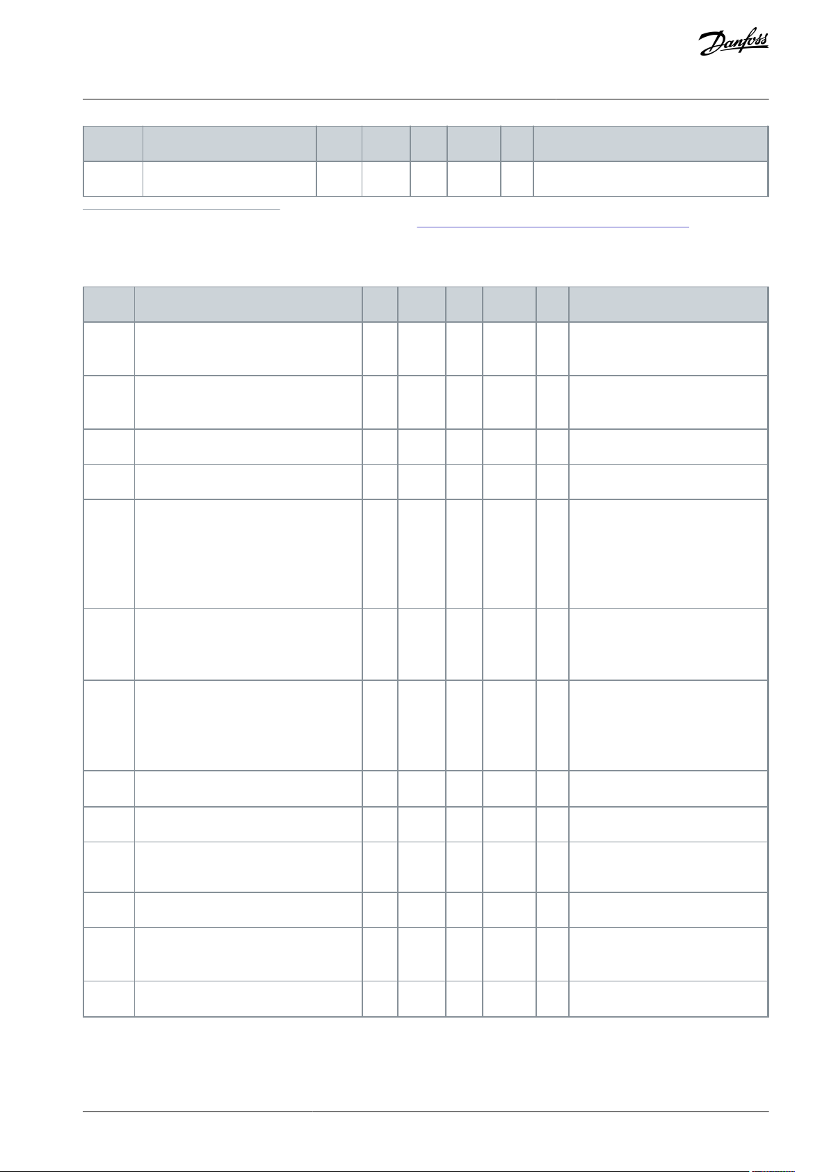
Index
Parameter
Min
Max
Unit
Default
ID
Description
P2.3.27
(1)
Analog output 2 scaling
10
1000%1.00
476
-
Index
Parameter
Min
Max
Unit
Default
ID
Description
P2.4.1
Ramp 1 shape
0.0
10.0s0.1
500
0 = Linear
100 = full acc/dec inc/dec tmes
P2.4.2
Ramp 2 shape
0.0
10.0s0.0
501
0 = Linear
100 = full acc/dec inc/dec tmes
P2.4.3
Acceleration time 2
0.1
3000.0
s
1.0
502-P2.4.4
Deceleration time 2
0.1
3000.0
s
1.0
503
-
P2.4.5
Brake chopper
0
4-0
504
0 = Disabled
1 = Used when running
2 = External brake chopper
3 = Used when stopped/running
4 = Used when running (no testing)
P2.4.6
Start function
0
2-0
505
0 = Ramp
1 = Flying start
2 = Conditional flying start
P2.4.7
Stop function
0
3-0
506
0 = Coasting
1 = Ramp
2 = Ramp+Run enable coast
3 = Coast+Run enable ramp
P2.4.8
DC braking current
0.00
ILA
0.7 x I
H
507
-
P2.4.9
DC braking time at stop
0.00
600.00
s
0.00
508
0 = DC brake is off at stop
P2.4.10
Frequency to start DC braking during
ramp stop
0.10
10.00
Hz
1.50
515
P2.4.11
DC braking time at start
0.00
600.00
s
0.00
516
0 = DC brake is off at start
P2.4.12
Flux brake
0
1-0
520
0 = Off
1 = On
P2.4.13
Flux braking current
0.00
ILA
IH519
-
VACON® NX All-in-One
Multi-step Speed Control
Application Guide
1
Use the Terminal to Function method (TTF) with these parameters, see 10.619 "Terminal to Function" (TTF) Programming Principle.
5.4.5 Drive Control Parameters (Control Panel: Menu M2->G2.4)
Table 29: Drive Control Parameters, G2.4
Application
AB296635287482en-000201 / DPD00903 | 53Danfoss A/S © 2020.12
Page 54

Index
Parameter
Min
Max
Unit
Default
ID
Description
P2.5.1
Prohibit frequency range 1 low limit
0.00
320.00
Hz
0.00
509-P2.5.2
Prohibit frequency range 1 high limit
0.00
320.00
Hz
0.00
510
0 = Prohibit range 1 is off
P2.5.3
Prohibit frequency range 2 low limit
0.00
320.00
Hz
0.00
511-P2.5.4
Prohibit frequency range 2 high limit
0.00
320.00
Hz
0.00
512
0 = Prohibit range 2 is off
P2.5.5
Prohibit frequency range 3 low limit
0.00
320.00
Hz
0.00
513-P2.5.6
Prohibit frequency range 3 high limit
0.00
320.00
Hz
0.00
514
0 = Prohibit range 3 is off
P2.5.7
Prohibit acc./dec. ramp
0.1
10.0x1.0
518
-
Index
Parameter
Min
Max
Unit
Default
ID
Description
P2.6.1
(1)
Motor control mode
0
1/4-0
600
0 = Frequency control
1 = Speed control
VACON® NXP:
2 = Open loop torque control
3 = Closed loop speed ctrl
4 = Closed loop torque control
P2.6.2
(1)
U/f optimisation
0
1-0
109
0 = Not used
1 = Automatic torque boost
P2.6.3
(1)
U/f ratio selection
0
3-0
108
0 = Linear
1 = Squared
2 = Programmable
3 = Linear with flux optim.
P2.6.4
(1)
Field weakening point
8.00
320.00
Hz
50.00
602
-
P2.6.5
(1)
Voltage at field weakening point
10.00
200.00
%
100.00
603
-
P2.6.6
(1)
U/f curve midpoint frequency
0.00
P2.6.4
Hz
50.00
604
-
P2.6.7
(1)
U/f curve midpoint voltage
0.00
100.00
%
100.00
605
-
P2.6.8
(1)
Output voltage at zero frequency
0.00
40.00
%
Varies
606-P2.6.9
Switching frequency
1.0
Varies
kHz
Varies
601
-
P2.6.10
Overvoltage controller
0
2-1
607
0 = Not used
1 = Used (no ramping)
2 = Used (ramping)
VACON® NX All-in-One
Application Guide
5.4.6 Prohibit Frequency Parameters (Control Panel: Menu M2 -> G2.5)
Table 30: Prohibit Frequency Parameters, G2.5
Multi-step Speed Control
Application
5.4.7 Motor Control Parameters (Control Panel: Menu M2 -> G2.6)
Table 31: Motor Control Parameters, G2.6
AB296635287482en-000201 / DPD0090354 | Danfoss A/S © 2020.12
Page 55

Index
Parameter
Min
Max
Unit
Default
ID
Description
P2.6.11
Undervoltage controller
0
2-2
608
0 = Not used
1 = Used
2 = Used (ramping to zero)
P2.6.12
Load drooping
0.00
100.00
%
0.00
620
-
P2.6.13
Identification
0
2/5-0
631
0 = No action
1 = Identification w/o run
2 = Identification with run
Only VACON® NXP:
3 = Encoder ID run
4 = No action
5 = ID Run Failed
Closed Loop parameter group 2.6.14
P2.6.14.1
Magnetizing current
0.00
2 x IHA
0.00
612
-
P2.6.14.2
Speed control P gain
1
1000-30
613-P2.6.14.3
Speed control I time
0.0
3200.0
ms
30.0
614-P2.6.14.5
Acceleration compensation
0.00
300.00
s
0.00
626-P2.6.14.6
Slip adjust
0
500%100
619
-
P2.6.14.7
Magnetizing current at start
0.00
ILA
0.00
627
-
P2.6.14.8
Magnetizing time at start
0
60000
ms0628-P2.6.14.9
0-speed time at start
0
32000
ms
100
615-P2.6.14.10
0-speed time at stop
0
32000
ms
100
616
-
P2.6.14.11
Start-up torque
0
3-0
621
0 = Not used
1 = Torque memory
2 = Torque reference
3 = Start-up torque fwd/rev
P2.6.14.12
Start-up torque FWD
-300.0
300.0
%
0.0
633-P2.6.14.13
Start-up torque REV
-300.0
300.0
%
0.0
634-P2.6.14.15
Encoder filter time
0.0
100ms0.0
618-P2.6.14.17
Current control P gain
0.00
100.00
%
40.00
617
-
Identification parameter group 2.6.15
P2.6.15.1
Speed step
-50.0
50.0-0.0
1252
-
VACON® NX All-in-One
Application Guide
Multi-step Speed Control
Application
1
Parameter value can only be changed after the AC drive has been stopped.
AB296635287482en-000201 / DPD00903 | 55Danfoss A/S © 2020.12
Page 56

Index
Parameter
Min
Max
Unit
Default
ID
Description
P2.7.1
Response to 4 mA reference fault
0
5-0
700
0 = No response
1 = Warning
2 = Warning+Previous Freq.
3 = Wrng+Preset- Freq 2.7.2
4 = Fault, stop acc. to 2.4.7
5 = Fault, stop by coasting
P2.7.2
4 mA reference fault frequency
0.00
P2.1.2
Hz
0.00
728-P2.7.3
Response to external fault
0
3-2
701
0 = No response
1 = Warning
2 = Fault, stop acc. to 2.4.7
3 = Fault, stop by coasting
P2.7.4
Input phase supervision
0
3-3
730
P2.7.5
Response to undervoltage fault
0
1-0
727
0 = Fault stored in history
1 = Fault not stored
P2.7.6
Output phase supervision
0
3-2
702
0 = No response
1 = Warning
2 = Fault, stop acc. to 2.4.7
3 = Fault, stop by coasting
P2.7.7
Earth fault protection
0
3-2
703
P2.7.8
Thermal protection of the motor
0
3-2
704
P2.7.9
Motor ambient temperature factor
-100.0
100.0
%
0.0
705-P2.7.10
Motor cooling factor at zero speed
0.0
150.0
%
40.0
706-P2.7.11
Motor thermal time constant
1
200
min
Varies
707-P2.7.12
Motor duty cycle
0
150%100
708
-
P2.7.13
Stall protection
0
3-0
709
0 = No response
1 = Warning
2 = Fault, stop acc. to 2.4.7
3 = Fault, stop by coasting
P2.7.14
Stall current
0.00
2 x IHA
IH710
-
P2.7.15
Stall time limit
1.00
120.00
s
15.00
711-P2.7.16
Stall frequency limit
1.0
P2.1.2
Hz
25.00
712
-
P2.7.17
Underload protection
0
3-0
713
0 = No response
1 = Warning
2 = Fault, stop acc. to 2.4.7
3 = Fault, stop by coasting
P2.7.18
Field weakening area load
10.0
150.0
%
50.0
714
-
VACON® NX All-in-One
Application Guide
5.4.8 Protections (Control Panel: Menu M2 -> G2.7)
Table 32: Protections, G2.7
Multi-step Speed Control
Application
AB296635287482en-000201 / DPD0090356 | Danfoss A/S © 2020.12
Page 57
Index
Parameter
Min
Max
Unit
Default
ID
Description
P2.7.19
Zero frequency load
5.0
150.0
%
10.0
715-P2.7.20
Underload protection time limit
2.00
600.00
s
20.00
716-P2.7.21
Response to thermistor fault
0
3-2
732
0 = No response
1 = Warning
2 = Fault, stop acc. to 2.4.7
3 = Fault, stop by coasting
P2.7.22
Response to fieldbus fault
0
3-2
733
P2.7.23
Response to slot fault
0
3-734
Index
Parameter
Min
Max
Unit
Default
ID
Description
P2.8.1
Wait time
0.10
10.00
s
0.50
717-P2.8.2
Trial time
0.00
60.00
s
30.00
718
-
P2.8.3
Start function
0
2-0
719
0 = Ramp
1 = Flying start
2 = According to P2.4.6
P2.8.4
Number of tries after undervoltage trip
0
10-0
720-P2.8.5
Number of tries after overvoltage trip
0
10-0
721-P2.8.6
Number of tries after overcurrent trip
0
3-0
722-P2.8.7
Number of tries after 4 mA reference trip
0
10-0
723-P2.8.8
Number of tries after motor temperature fault trip
0
10-0
726-P2.8.9
Number of tries after external fault trip
0
10-0
725-P2.8.10
Number of tries after underload fault trip
0
10-0
738
-
Index
Parameter
Min
Max
Unit
Default
ID
Description
P3.1
Control place
1
3-1
125
1 = I/0 terminal
2 = Keypad
3 = Fieldbus
P3.2
Keypad reference
P2.1.1
P2.1.2
Hz
0.00
-
-
P3.3
Direction (on keypad)
0
1-0
123
0 = Forward
VACON® NX All-in-One
Application Guide
5.4.9 Autorestart Parameters (Control Panel: Menu M2 -> G2.8)
Table 33: Autorestart Parameters, G2.8
Multi-step Speed Control
Application
5.4.10 Keypad Control (Control Panel: Menu M3)
The parameters for the selection of control place and direction on the keypad are listed in this table. See the Keypad control menu in
the User Manual of the product.
Table 34: Keypad Control Parameters, M3
AB296635287482en-000201 / DPD00903 | 57Danfoss A/S © 2020.12
Page 58

Index
Parameter
Min
Max
Unit
Default
ID
Description
1 = Reverse
R3.4
Stop button
0
1-1
114
0 = Limited function of Stop button
1 = Stop button always enabled
VACON® NX All-in-One
Multi-step Speed Control
Application Guide
Application
5.4.11 System Menu (Control Panel: Menu M6)
For more information related to the general use of the AC drive, such as selecting application and language, customized parameter
sets, or hardware and software, see the User Manual of the product.
5.4.12 Expander Boards (Control Panel: Menu M7)
The M7 menu shows the expander and option boards attached to the control board and board-related information. For more information, see the User Manual of the product.
AB296635287482en-000201 / DPD0090358 | Danfoss A/S © 2020.12
Page 59

VACON® NX All-in-One
Application Guide
PID Control Application
6 PID Control Application
6.1 Introduction to PID Control Application
Select the PID Control Application in menu M6 on page S6.2.
In the PID Control Application, there are two I/O terminal control places; place A is the PID controller and source B is the direct
frequency reference. The control place A or B is selected with digital input DIN 6.
The PID controller reference can be selected from the analog inputs, fieldbus, motorized potentiometer, enabling the PID Reference
2 or applying the keypad reference. The PID controller actual value can be selected from the analog inputs, fieldbus, the actual
values of the motor or through the mathematical functions of these.
The direct frequency reference can be used for the control without the PID controller and selected from the analog inputs, fieldbus,
motor potentiometer, or keypad.
The PID Application is typically used to control level measuring or pumps and fans. In these applications, the PID Application provides a smooth control and an integrated measuring and controlling package where no additional components are needed.
•
Digital inputs DIN 2, DIN 3, DIN 5 and all the outputs are freely programmable.
Extra functions:
•
Analog input signal range selection
•
Two frequency limit supervisions
•
Torque limit supervision
•
Reference limit supervision
•
Second ramps and S-shape ramp programming
•
Programmable start and stop functions
•
DC brake at start and stop
•
Three prohibit frequency areas
•
Programmable U/f curve and switching frequency
•
Auto restart
•
Motor thermal and stall protection: fully programmable; off, warning, fault
•
Motor underload protection
•
Input and output phase supervision
•
Sum point frequency addition to PID output
•
The PID controller can be also used from control places I/O B, keypad, and fieldbus
•
Easy ChangeOver function
•
Sleep function
The parameters of the PID Control Application are explained in Chapter Parameter descriptions of this manual. The explanations are
arranged according to the individual ID number of the parameter.
AB296635287482en-000201 / DPD00903 | 59Danfoss A/S © 2020.12
Page 60

-
+
1
6
2
3
4
5
18
19
20
12
7
13
8
9
10
14
15
16
21
22
23
11
17
24
25
26
2-wire
Transmitter
Reference potentiometer,
1-10kΩ
mA
RUN
READY
AO1-
DO1
+24 V
GND
GND
DIN1
DIN2
DIN3
DIN4
DIN5
DIN6
R
O1
R
O1
R
O1
CMA
CMB
R
O2
R
O2
R
O2
OPTA1
OPTA2 / OPTA3
Terminal Signal Description
+10V
ref
AI1+
AI1-
AI2+
AI2-
+24V
Reference output
I/O Ground
Analogue input 2
Current range
0—20mA
Programmable
(P2.2.9)
Control voltage output
I/O ground
Place A: Start forward
Ri min. = 5kΩ
Fault reset
Programmable (P2.2.2)
External fault input
Programmable (P2.2.2)
Place B: Start forward
Ri min. = 5 kΩ
Jogging speed selection
Programmable (P2.2.3)
Control place A/B selection
Contact closed = Jogging speed active
Start signal for control place B
Frequency reference (P2.2.5.)
Common for DIN 1—DIN 3
Common for DIN4—DIN6
Control voltage output
I/O ground
Analogue output 1
Output frequency
Programmable (P2.3.2)
Digital output
READY
Programmable (P2.3.7)
Open collector,
I≤50 mA, U≤48 VDC
Relay output 1
RUN
Programmable
(P2.3.8)
Relay output 2
FAULT
Programmable
(P2.3.9)
AO1+
Analogue input 1
PID reference
Ground for reference
and controls
Analogue input 2
PID actual value 1
Contact closed = start forward
Contact closed = fault reset
Contact closed = start reverse
Contact closed = fault
Contact open = no fault
Reference voltage for potentiometer, etc.
Analogue input 1
Voltage range 0—10V DC
Programmable (P2.1.11)
Voltage for switches,
etc. max 0.1 A
Voltage for switches (see #6)
Connect to GND or +24 V
Actual
value
(0) 4-20
mA
Contact open = Control place A
is active Contact closed =
Control place B is active
Connect to GND or +24 V
Ground for reference and controls
Ground for reference and controls
Range 0—20 mA/RL,
max. 500 Ω
e30bh097.20
VACON® NX All-in-One
Application Guide
6.2 Control I/O in PID Control Application
Illustration 14: Default I/O Configuration in PID Control Application
The option board OPTA3 has no terminal for open contact on its second relay output (terminal 24 is missing).
See jumper selections in Illustration 15. More information in the User Manual of the product.
PID Control Application
AB296635287482en-000201 / DPD0090360 | Danfoss A/S © 2020.12
Page 61

Jumper block X3:
CMA and CMB grounding
CMB connected to GND
CMA connected to GND
CMB isolated from GND
CMA isolated from GND
CMB and CMA internally
connected together,isolated
from GND
= Factory default
e30bh013.10
VACON® NX All-in-One
Application Guide
Illustration 15: Jumper Selections
PID Control Application
AB296635287482en-000201 / DPD00903 | 61Danfoss A/S © 2020.12
Page 62

DIN2
DIN5
DIN3
DIN6
AI1
AI2
0
1
2
3
4
0
1
2
3
4
5
+A
A
B
0
1
2
3
4
5
0
1
2
3
4
5
K
0
1
2
3
4
5
F
PID
+
DIN1
DIN4
A
B
A
B
A/B
Internal reverse
Internal fault reset
Fault reset input (programmable)
3.3 Keypad direction
Internal Start/Stop
Reference from fieldbus
Start/Stop from fieldbus
Direction from fieldbus
External fault (programmable)
Jogging speed (programmable)
Place A/B selection
2.2.4 PID main reference
Up
Down
2.1.11 PID reference
I/O reverse
R3.4 PID keypad refer.
R3.2 Keypad refer.
Act 1
Act 2
R3.5 PID keypad ref. 2
Enable PID keypad
ref. 2 (DIN5=13)
Start; Place A
Start; Place B
Start/Stop
Start/Stop buttons
Internal
frequency ref.
2.1.19 Jogging speed ref.
Keypad
Fieldbus
Reset button
3.1 Control place
2.2.7 Fieldbus Ctrl Reference
2.2.6 Keypad Crtl Reference
2.2.5 I/O B Reference
≥ 1
Motor
potentiometer
Actual value
selection,
par. 2.2.9 &
2.2.10
Actual value
selection par.
2.2.8
e30bh053.10
Index
Monitoring value
Unit
Form
ID
Description
V1.1
Output frequency
Hz
#.##1-
V1.2
Frequency reference
Hz
#.##25-
V1.3
Motor speed
RPM#2
-
VACON® NX All-in-One
Application Guide
6.3 Control Signal Logic in PID Control Application
PID Control Application
Illustration 16: Control Signal Logic of the PID Control Application
6.4 Parameter Lists for PID Control Application
6.4.1 Monitoring Values (Control Panel: Menu M1)
The monitoring values are the actual values of parameters and signals as well as statuses and measurements. Monitoring values
cannot be edited.
The monitoring values V1.19 to V1.22 are available with the PID control application only.
Table 35: Monitoring Values
AB296635287482en-000201 / DPD0090362 | Danfoss A/S © 2020.12
Page 63

Index
Monitoring value
Unit
Form
ID
Description
V1.4
Motor current
A
Varies
3-V1.5
Motor torque
%
#.#4-
V1.6
Motor shaft power
%
#.#5-
V1.7
Motor voltage
V
#.#6-
V1.8
DC-link voltage
V#7-V1.9
Unit temperature
°C#8-V1.10
Motor temperature
%
#.#9-
V1.11
Analog input 1
V/mA
#.##13-
V1.12
Analog input 2
V/mA
#.##14-
V1.13
Analog input 3
--27-V1.14
Analog input 4
--28-V1.15
DIN 1, 2,3
--15-V1.16
DIN 4, 5, 6
--16-V1.17
DO1, RO1, RO2
--17
-
V1.18
Analog I
out
mA
#.##26-
V1.19
PID Reference
%-20-V1.20
PID Actual value
%-21-V1.21
PID Error value
%-22-V1.22
PID Output
%-23-V1.23
Special display for actual value
--29-V1.24
PT-100 Temperature
ºC
#.#42-
G1.25
Monitoring items
----V1.26.1
Current
A
Varies
1113-V1.26.2
Torque
%
#.#
1125-V1.26.3
DC Voltage
V#44-V1.26.4
Status Word
--43
-
Index
Parameter
Min
Max
Unit
Default
ID
Description
P2.1.1
Min frequency
0.00
P2.1.2
Hz
0.00
101-P2.1.2
Max frequency
P2.1.1
320.00
Hz
50.00
102
-
VACON® NX All-in-One
Application Guide
PID Control Application
6.4.2 Basic Parameters (Keypad Panel: Menu M2 -> G2.1)
Table 36: Basic Parameters G2.1
AB296635287482en-000201 / DPD00903 | 63Danfoss A/S © 2020.12
Page 64

Index
Parameter
Min
Max
Unit
Default
ID
Description
P2.1.3
Acceleration time 1
0.1
3000.0
s
0.0
103-P2.1.4
Deceleration time 1
0.1
3000.0
s
0.0
104
-
P2.1.5
Current limit
0.1 x I
H
2 x IHA
IL107
-
P2.1.6
(1)
Nominal voltage of the motor
180
690VNX2: 230 V
NX5: 400 V
NX6: 690 V
110
-
P2.1.7
(1)
Nominal frequency of the motor
8.00
320.00
Hz
50.00
111
-
P2.1.8
(1)
Nominal speed of the motor
24
20 000
RPM
1440
112
-
P2.1.9
(1)
Nominal current of the motor
0.1 x I
H
2 X IHA
IH113
-
P2.1.10
(1)
Motor cos phi
0.30
1.00-0.85
120
-
P2.1.11
(1)
PID controller reference signal (Place
A)
0
4-1
332
0 = AI 1
1 = AI 2
2 = PID ref from Keypad con-
trol page, P3.4
3 = PID ref from fieldbus
(Process- DataIN 1)
4 = Motor potentiometer
P2.1.12
PID controller gain
0.0
1000.0
%
100.0
118-P2.1.13
PID controller I-time
0.00
320.00
s
1.00
119-P2.1.14
PID controller D-time
0.00
100.00
s
0.00
132-P2.1.15
Sleep frequency
0.00
P2.1.2
Hz
10.00
1016-P2.1.16
Sleep delay
0
3600s30
1017-P2.1.17
Wake up level
0.00
100.00
%
25.00
1018
-
P2.1.18
Wake up function
0
1-0
1019
0 = Wake-up at fall below
wake-up level (P2.1.17)
1 = Wake-up at exceeded
wake-up level (P2.1.17)
P2.1.19
Jogging speed reference
0.00
P2.1.2
Hz
10.00
124
-
VACON® NX All-in-One
Application Guide
PID Control Application
1
Parameter value can only be changed after the AC drive has been stopped.
AB296635287482en-000201 / DPD0090364 | Danfoss A/S © 2020.12
Page 65

Index
Parameter
Min
Max
Unit
Default
ID
Description
P2.2.1
(1)
DIN 2 function
0
13-1
319
0 = Not used
1 = External fault cc
2 = External fault oc
3 = Run enable
4 = Acc/Dec time selection
5 = CP: I/O terminal (ID125)
6 = CP: Keypad (ID125)
7 = CP: Fieldbus (ID125)
8 = Forward/ Reverse
9 = Jogging frequency (cc)
10 = Fault reset (cc)
11 = Acc/Dec prohibit (cc)
12 = DC braking command
13 = Motor pot. UP (cc)
P2.2.2
(1)
DIN 3 function
0
13-10
301
See P2.2.1 except:
13 = Motor pot. DOWN (cc)
P2.2.3
(1)
DIN 5 function
0
13-9
330
See P2.2.1 except:
13 = Enable PID reference 2
P2.2.4
(1)
PID sum point reference
0
7-0
376
0 = Direct PID output value
1 = AI1+PID output
2 = AI2+PID output
3 = AI3+PID output
4 = AI4+PID output
5 = PID keypad +PID output
6 = Fieldbus+PID output (Process- DataIN3)
7 = Mot.pot.+PID output
P2.2.5
(1)
I/O B reference selection
0
7-1
343
0 = AI1 1 = AI2
2 = AI3
3 = AI4
4 = Keypad reference
5 = Fieldbus reference (FBSpeedReference)
6 = Motor potentiometer
7 = PID controller
P2.2.6
(1)
Keypad control reference selection
0
7-4
121
P2.2.7
(1)
Fieldbus control reference selection
0
7-5
122
P2.2.8
(1)
Actual value selection
0
7-0
333
0 = Actual value 1
1 = Actual 1 + Actual 2
2 = Actual 1 – Actual 2
3 = Actual 1 x Actual 2
4 = Min(Actual 1, Actual 2)
5 = Max(Actual 1, Actual 2)
6 = Mean (Actual1, Actual2
7 = Sqrt (Actual 1) + Sqrt (Actual 2)
P2.2.9
(1)
Actual value 1 selection
0
10-2
334
0 = Not used
VACON® NX All-in-One
Application Guide
6.4.3 Input Signals (Control Panel: Menu M2 -> G2.2)
Table 37: Input Signals, G2.2
PID Control Application
AB296635287482en-000201 / DPD00903 | 65Danfoss A/S © 2020.12
Page 66

Index
Parameter
Min
Max
Unit
Default
ID
Description
1 = AI1 signal (cboard)
2 = AI2 signal (cboard)
3 = AI3
4 = AI4
5 = Fieldbus ProcessDataIN2
6 = Motor torque
7 = Motor speed
8 = Motor current
9 = Motor power
10 = Encoder frequency
P2.2.10
(1)
Actual value 2 input
0
10-0
335
0 = Not used
1 = AI1 signal
2 = AI2 signal
3 = AI3
4 = AI4
5 = Fieldbus ProcessDataIN3
6 = Motor torque
7 = Motor speed
8 = Motor current
9 = Motor power
10 = Encoder Frequency
P2.2.11
Actual value 1 minimum scale
–1600.0
1600.0
%
0.0
336
0 = No minimum scaling
P2.2.12
AI2 custom setting
maximum
–1600.0
1600.0
%
100.0
337
100 = No maximum scaling
P2.2.13
AI2 signal inversion
–1600.0
1600.0
%
0.0
338
0 = No minimum scaling
P2.2.14
AI2 signal filter time
–1600.0
1600.0
%
100.0
339
100 = No maximum scaling
P2.2.15
(2)
AI1 signal selection
0.1
E.10-A.1
377
-
P2.2.16
(3)
AI1 signal range
0
2-0
320
0 = 0–10 V (0–20 mA)
1 = 2–10 V (4–20 mA)
2 = Custom range
P2.2.17
AI1 custom minimum
setting
–160.00
160.00
%
0.00
321-P2.2.18
Free analog input, function
–160.00
160.00
%
100.0
322
-
P2.2.19
AI1 inversion
0
1-0
323
0 = Not inverted
1 = Inverted
P2.2.20
AI1 filter time
0.00
10.00
s
0.10
324
-
P2.2.21
(3)
AI2 signal selection
0.1
E.10-A.2
388
0 = 0–20 mA (0–10 V)
1 = 4–20 mA (2–10 V)
VACON® NX All-in-One
Application Guide
PID Control Application
AB296635287482en-000201 / DPD0090366 | Danfoss A/S © 2020.12
Page 67

Index
Parameter
Min
Max
Unit
Default
ID
Description
2 = Custom range
P2.2.22
(3)
AI2 signal range
0
2-1
325
0 = 0–20 mA
1 = 4–20 mA
2 = Customised
P2.2.23
AI2 custom minimum
setting
-160.00
160.00
%
0.00
326-P2.2.24
AI2 custom maximum
setting
-160.00
160.00
%
0.00
327
-
P2.2.25
AI2 inversion
0
1-0
328
0 = Not inverted
1 = Inverted
P2.2.26
AI2 filter time
0.00
10.00
s
0.10
329
0 = No filtering
P2.2.27
Motor potentiometer
ramp time
0.1
2000.0
Hz/s
10.0
331
-
P2.2.28
Motor potentiometer
frequency reference
memory reset
0
2-1
367
0 = No reset
1 = Reset if stopped or powered down
2 = Reset if powered down
P2.2.29
Motor potentiometer
PID reference memory
reset
0
2-0
370
P2.2.30
PID minimum limit
-1600.0
P2.2.31
%
0.0
359-P2.2.31
PID maximum limit
P2.2.30
1600.0
%
100.0
360
-
P2.2.32
Error value inversion
0
1-0
340
0 = No inversion
1 = Inversion
P2.2.33
PID reference rising
time
0.1
100.0
s
5.0
341-P2.2.34
PID reference falling
time
0.1
100.0
s
5.0
342-P2.2.35
Reference scaling minimum value, place B
0.00
320.0
Hz
0.00
344-P2.2.36
Reference scaling maximum value, place B
0.00
320.0
Hz
0.00
345
-
P2.2.37
Easy changeover
0
1-0
366
0 = Keep reference
1 = Copy actual reference
P2.2.38
(2)
AI3 signal selection
0.1
E.10-0.1
141
-
P2.2.39
AI3 signal range
0
1-1
143
0 = Signal range 0–10 V
1 = Signal range 2–10 V
VACON® NX All-in-One
Application Guide
PID Control Application
AB296635287482en-000201 / DPD00903 | 67Danfoss A/S © 2020.12
Page 68

Index
Parameter
Min
Max
Unit
Default
ID
Description
P2.2.40
AI3 inversion
0
1-0
151
0 = Not inverted
1 = Inverted
P2.2.41
AI3 filter time
0.00
10.00
s
0.10
142
0 = No filtering
P2.2.42
(2)
AI4 signal selection
0.1
E.10-0.1
152
-
P2.2.43
AI4 signal range
0
1-1
154
0 = Signal range 0–10 V
1 = Signal range 2–10 V
P2.2.44
AI4 inversion
0
1-0
162
0 = Not inverted
1 = Inverted
P2.2.45
AI4 filter time
0.00
10.00
s
0.10
153
0 = No filtering
P2.2.46
Actual value special display minimum
0
30000
-
0
1033-P2.2.47
Actual value special display maximum
0
30000
-
100
1034-P2.2.48
Actual value special display decimals
0
4-1
1035-P2.2.49
Actual value special display unit
0
29-4
1036
See 10.437 (ID 1036) Actual Value Special Dis-
play Unit.
Index
Parameter
Min
Max
Unit
Default
ID
Description
P2.3.1
(1)
Analog output 1 signal selection
0.1
E.10-A.1
464
-
P2.3.2
Analog output function
0
14-1
307
0 = Not used
1 = Output freq. (0–f
max
)
2 = Freq. reference (0–f
max
)
3 = Motor speed (0–Motor nominal speed)
4 = Motor current (0–I
nMotor
)
5 = Motor torque (0–T
nMotor
)
6 = Motor power (0–P
nMotor
)
7 = Motor voltage (0–U
nMotor
)
8 = DC-link volt (0–1000 V)
VACON® NX All-in-One
Application Guide
PID Control Application
1
Parameter value can only be changed after the AC drive has been stopped.
2
Use the Terminal to Function method (TTF) with these parameters, see
3
Remember to place jumpers of block X2 according to the selection (0, 1 or 2). See the User Manual of the product.
CP = control place
cc = closing contact
oc = opening contact
6.4.4 Output Signals (Control Panel: Menu M2 -> G2.3)
Table 38: Output Signals, G2.3
10.619 "Terminal to Function" (TTF) Programming Principle.
AB296635287482en-000201 / DPD0090368 | Danfoss A/S © 2020.12
Page 69

Index
Parameter
Min
Max
Unit
Default
ID
Description
9 = PID controller ref. value
10 = PID contr. act. value 1
11 = PID contr. act. value 2
12 = PID contr. error value
13 = PID controller output
14 = PT100 temperature
P2.3.3
Analog output filter time
0.00
10.00
s
1.00
308
0 = No filtering
P2.3.4
Analog output inversion
0
1-0
309
0 = Not inverted
1 = Inverted
P2.3.5
Analog output minimum
0
1-0
310
0 = 0 mA (0 V)
1 = 4 mA (2 V)
P2.3.6
Analog output scale
10
1000%100
311-P2.3.7
Digital output 1 function
0
23-1
312
0 = Not used
1 = Ready
2 = Run
3 = Fault
4 = Fault inverted
5 = AC drive overheat warning
6 = Ext. fault or warning
7 = Ref. fault or warning
8 = Warning
9 = Reversed
10 = Preset speed 1
11 = At speed
12 = Mot. regulator active
13 = OP freq. limit superv. 1
14 = OP freq. limit superv.2
15 = Torque limit superv.
16 = Ref. limit superv.
17 = Ext. brake control
18 = Control place: I/O
19 = AC drive temp. limit superv.
20 = Unrequested rotation direction
21 = Ext. brake control inverted
22 = Thermistor fault/warn.
23 = Fieldbus DIN 1
P2.3.8
RO1 function
0
23-2
313
P2.3.9
RO2 function
0
23-3
314
P2.3.10
Output frequency limit 1 supervision
0
2-0
315
0 = No limit
1 = Low limit supervision
2 = High limit supervision
P2.3.11
Output frequency limit 1; Supervised value
0.00
320.00
Hz
0.00
316
-
P2.3.12
Output frequency limit 2 supervision
0
2-0
346
0 = No limit
1 = Low limit supervision
VACON® NX All-in-One
Application Guide
PID Control Application
AB296635287482en-000201 / DPD00903 | 69Danfoss A/S © 2020.12
Page 70

Index
Parameter
Min
Max
Unit
Default
ID
Description
2 = High limit supervision
P2.3.13
Output frequency limit 2; Supervision value
0.00
320.00
Hz
0.00
347
-
P2.3.14
Torque limit supervision function
0
2-0
348
0 = No
1 = Low limit
2 = High limit
P2.3.15
Torque limit supervision value
-300.0
300.0
%
100.0
349
-
P2.3.16
Reference limit supervision
function
0
2-0
350
0 = No
1 = Low limit
2 = High limit
P2.3.17
Reference limit supervision value
0.0
100.0
%
0.0
351
P2.3.18
External brake Off-delay
0.0
100.0
s
0.5
352-P2.3.19
External brake On-delay
0.0
100.0
s
1.5
353
-
P2.3.20
Frequency converter temperature limit supervision
0
2-0
354
0 = No
1 = Low limit
2 = High limit
P2.3.21
Frequency converter temperature limit value
-10
100°C40
355
P2.3.22
Analogue output 2 scaling
0.1
E.10-0.1
471
-
P2.3.23
Analogue output 2 function
0
14-4
472
As parameter 2.3.2
P2.3.24
Analog output 2 filter time
0.00
10.00
s
1.00
473
0 = No filtering
P2.3.25
Analog output 2 inversion
0
1-0
474
0 = Not inverted
1 = Inverted
P2.3.26
Analog output 2 minimum
0
1-0
475
0 = 0 mA (0 V)
1 = 4 mA (2 V)
P2.3.27
Analog output 2 scaling
10
1000%1.00
476
-
Index
Parameter
Min
Max
Unit
Default
ID
Description
P2.4.1
Ramp 1 shape
0.0
10.0s0.1
500
0 = Linear
>0 = S-curve ramp time
VACON® NX All-in-One
Application Guide
PID Control Application
1
Use the Terminal to Function method (TTF) with these parameters, see
6.4.5 Drive Control Parameters (Control Panel: Menu M2 -> G2.4)
Table 39: Drive Control Parameters, G2.4
10.619 "Terminal to Function" (TTF) Programming Principle.
AB296635287482en-000201 / DPD0090370 | Danfoss A/S © 2020.12
Page 71

Index
Parameter
Min
Max
Unit
Default
ID
Description
P2.4.2
Ramp 2 shape
0.0
10.0s0.0
501
0 = Linear
>0 = S-curve ramp time
P2.4.3
Acceleration time 2
0.1
3000.0
s
1.0
502-P2.4.4
Deceleration time 2
0.1
3000.0
s
1.0
503
-
P2.4.5
Brake chopper
0
4-0
504
0 = Disabled
1 = Used when running
2 = External brake chopper
3 = Used when stopped/running
4 = used when running (no testing)
P2.4.6
Start function
0
2-0
505
0 = Ramp
1 = Flying start
2 = Conditional flying start
P2.4.7
Stop function
0
3-0
506
0 = Coasting
1 = Ramp
2 = Ramp+Run enable coast
3 = Coast+Run enable ramp
P2.4.8
DC braking current
0.00
ILA
0.7 x I
H
507
-
P2.4.9
DC braking time at stop
0.00
600.00
s
0.00
508
0 = DC brake is off at stop
P2.4.10
Frequency to start DC braking during
ramp stop
0.10
10.00
Hz
1.50
515
P2.4.11
DC braking time at start
0.00
600.00
s
0.00
516
0 = DC brake is off at start
P2.4.12
Flux brake
0
1-0
520
0 = Off
1 = On
P2.4.13
Flux braking current
0.00
ILA
IH519
-
Index
Parameter
Min
Max
Unit
Default
ID
Description
P2.5.1
Prohibit frequency range 1 low limit
-1.00
320.00
Hz
0.00
509
0 = Not used
P2.5.2
Prohibit frequency range 1 high limit
0.00
320.00
Hz
0.00
510
0 = Not used
P2.5.3
Prohibit frequency range 2 low limit
0.00
320.00
Hz
0.00
511
0 = Not used
P2.5.4
Prohibit frequency range 2 high limit
0.00
320.00
Hz
0.00
512
0 = Not used
P2.5.5
Prohibit frequency range 3 low limit
0.00
320.00
Hz
0.00
513
0 = Not used
VACON® NX All-in-One
Application Guide
PID Control Application
6.4.6 Prohibit Frequency Parameters (Control Panel: Menu M2 -> G2.5)
Table 40: Prohibit Frequency Parameters, G2.5
AB296635287482en-000201 / DPD00903 | 71Danfoss A/S © 2020.12
Page 72

Index
Parameter
Min
Max
Unit
Default
ID
Description
P2.5.6
Prohibit frequency range 3 high limit
0.00
320.00
Hz
0.00
514
0 = Not used
P2.5.7
Prohibit acc./dec. ramp
0.1
10.0x1.0
518
-
Index
Parameter
Min
Max
Unit
Default
ID
Description
P2.6.1
Motor control mode
0
1/4-0
600
0 = Frequency control
1 = Speed control
VACON® NXP:
2 = Open loop torque control
3 = Closed loop speed ctrl
4 = Closed loop torque control
P2.6.2
U/f optimisation
0
1-0
109
0 = Not used
1 = Automatic torque boost
P2.6.3
U/f ratio selection
0
3-0
108
0 = Linear
1 = Squared
2 = Programmable
3 = Linear with flux optim.
P2.6.4
Field weakening point
8.00
320.00
Hz
50.00
602
-
P2.6.5
Voltage at field weakening point
10.00
200.00
%
100.00
603
-
P2.6.6
U/f curve midpoint frequency
0.00
P2.6.4
Hz
50.00
604
-
P2.6.7
U/f curve midpoint voltage
0.00
100.00
%
100.00
605
-
P2.6.8
Output voltage at zero frequency
0.00
40.00
%
Varies
606-P2.6.9
Switching frequency
1.0
Varies
kHz
Varies
601
-
P2.6.10
Overvoltage controller
0
2-1
607
0 = Not used
1 = Used (no ramping)
2 = Used (ramping)
P2.6.11
Undervoltage controller
0
2-1
608
0 = Not used
1 = Used
2 = Used (ramping to zero)
P2.6.12
Load drooping
0.00
100.00
%
0.00
620
-
P2.6.13
Identification
0
2/5-0
631
0 = No action
1 = Identification w/o run
2 = Identification with run
VACON® NXP only:
3 = Encoder ID run
VACON® NX All-in-One
Application Guide
6.4.7 Motor Control Parameters (Control Panel: Menu M2 -> G2.6)
Table 41: Motor Control Parameters, G2.6
PID Control Application
AB296635287482en-000201 / DPD0090372 | Danfoss A/S © 2020.12
Page 73
Index
Parameter
Min
Max
Unit
Default
ID
Description
4 = No action
5 = ID Run Failed
Closed Loop parameter group 2.6.14
P2.6.14.1
Magnetizing current
0.00
2 x IHA
0.00
612
-
P2.6.14.2
Speed control P gain
1
1000-30
613-P2.6.14.3
Speed control I time
0.0
3200.0
ms
30.0
614-P2.6.14.5
Acceleration compensation
0.00
300.00
%
0.00
626-P2.6.14.6
Slip adjust
0
500%100
619
-
P2.6.14.7
Magnetizing current at start
0.00
ILA
0.00
627
-
P2.6.14.8
Magnetizing time at start
0
60000
ms0628-P2.6.14.9
0-speed time at start
0
32000
ms
100
615-P2.6.14.10
0-speed time at stop
0
32000
ms
100
616
-
P2.6.14.11
Start-up torque
030
621
0 = Not used
1 = Torque memory
2 = Torque reference
3 = Start-up torque fwd/rev
P2.6.14.12
Start-up torque FWD
-300.0
300.0
%
0.0
633-P2.6.14.13
Start-up torque REV
-300.0
300.0
%
0.0
634-P2.6.14.15
Encoder filter time
0.0
100ms0.0
618-P2.6.14.17
Current control P gain
0.00
100.00
%
40.00
617
-
Identification parameter group 2.6.15
P2.6.15.1
Speed step
-50.0
50.0%0.0
1252
-
Index
Parameter
Min
Max
Unit
Default
ID
Description
P2.7.1
Response to 4 mA reference fault
0
5-4
700
0 = No response
1 = Warning
2 = Warning+Previous Freq.
3 = Wrng+Preset- Freq 2.7.2
4 = Fault, stop acc. to 2.4.7
5 = Fault, stop by coasting
P2.7.2
4 mA reference fault frequency
0.00
P2.1.2
Hz
0.00
728
-
VACON® NX All-in-One
Application Guide
PID Control Application
6.4.8 Protections (Control Panel: Menu M2 -> G2.7)
Table 42: Protections, G2.7
AB296635287482en-000201 / DPD00903 | 73Danfoss A/S © 2020.12
Page 74

Index
Parameter
Min
Max
Unit
Default
ID
Description
P2.7.3
Response to external fault
0
3-2
701
0 = No response
1 = Warning
2 = Fault, stop acc. to 2.4.7
3 = Fault, stop by coasting
P2.7.4
Input phase supervision
0
3-0
730
P2.7.5
Response to undervoltage fault
0
1-0
727
0 = Fault stored in history
1 = Fault not stored
P2.7.6
Output phase supervision
0
3-2
702
0 = No response
1 = Warning
2 = Fault, stop acc. to 2.4.7
3 = Fault, stop by coasting
P2.7.7
Earth fault protection
0
3-2
703
P2.7.8
Thermal protection of the motor
0
3-2
704
P2.7.9
Motor ambient temperature factor
-100.0
100.0
%
0.0
705-P2.7.10
Motor cooling factor at zero speed
0.0
150.0
%
40.0
706-P2.7.11
Motor thermal time constant
1
200
min
Varies
707-P2.7.12
Motor duty cycle
0
150%100
708
-
P2.7.13
Stall protection
031
709
0 = No response
1 = Warning
2 = Fault, stop acc. to 2.4.7
3 = Fault, stop by coasting
P2.7.14
Stall current
0.00
2 x IHA
IH710
-
P2.7.15
Stall time limit
1.00
120.00
s
15.00
711-P2.7.16
Stall frequency limit
1.0
P2.1.2
Hz
25.00
712
-
P2.7.17
Underload protection
030
713
0 = No response
1 = Warning
2 = Fault, stop acc. to 2.4.7
3 = Fault, stop by coasting
P2.7.18
UP From Torque
10.0
150.0
%
50.0
714-P2.7.19
UP Zero frequency load
5.0
150.0
%
10.0
715-P2.7.20
Underload protection time limit
2.00
600.00
s
20.00
716-P2.7.21
Response to thermistor fault
0
3-2
732
0 = No response
1 = Warning
2 = Fault, stop acc. to 2.4.7
3 = Fault, stop by coasting
P2.7.22
Response to fieldbus fault
0
3-2
733
P2.7.23
Response to slot fault
0
3-2
734
P2.7.24
No. of PT100 inputs
0
5-0
739
0 = Not used
1 = Channel 1
VACON® NX All-in-One
Application Guide
PID Control Application
AB296635287482en-000201 / DPD0090374 | Danfoss A/S © 2020.12
Page 75

Index
Parameter
Min
Max
Unit
Default
ID
Description
2 = Channel 1 & 2
3 = Channel 1 & 2 & 3
4 = Channel 2 & 3
5 = Channel 3
P2.7.25
Response to PT100 fault
0
3-0
740
0 = No response
1 = Warning
2 = Fault,stop acc. to 2.4.7
3 = Fault,stop by coasting
P2.7.26
PT100 warning limit
-30.0
200.0
ºC
120.0
741-P2.7.27
PT100 fault limit
-30.0
200.0
ºC
130.0
742
-
Index
Parameter
Min
Max
Unit
Default
ID
Description
P2.8.1
Wait time
0.10
10.00
s
0.50
717-P2.8.2
Trial time
0.00
60.00
s
30.00
718
-
P2.8.3
Start function
0
2-0
719
0 = Ramp
1 = Flying start
2 = According to P2.4.6
P2.8.4
Number of tries after undervoltage trip
0
10-0
720-P2.8.5
Number of tries after overvoltage trip
0
10-0
721-P2.8.6
Number of tries after overcurrent trip
0
3-0
722-P2.8.7
Number of tries after 4 mA reference trip
0
10-0
723-P2.8.8
Number of tries after motor temperature fault trip
0
10-0
726-P2.8.9
Number of tries after external fault trip
0
10-0
725-P2.8.10
Number of tries after underload fault trip
0
10-0
738
-
Index
Parameter
Min
Max
Unit
Default
ID
Description
P3.1
Control place
1
3-1
125
1 = I/0 terminal
2 = Keypad
3 = Fieldbus
VACON® NX All-in-One
Application Guide
6.4.9 Autorestart Parameters (Control Panel: Menu M2 -> G2.8)
Table 43: Autorestart Parameters, G2.8
PID Control Application
6.4.10 Keypad Control (Control Panel: Menu M3)
The parameters for the selection of control place and direction on the keypad are listed below. See the Keypad control menu in the
User Manual of the product.
Table 44: Keypad Control Parameters, M3
AB296635287482en-000201 / DPD00903 | 75Danfoss A/S © 2020.12
Page 76

Index
Parameter
Min
Max
Unit
Default
ID
Description
P3.2
Keypad reference
P2.1.1
P2.1.2
Hz
0.00
-
-
P3.3
Direction (on keypad)
0
1-0
123
0 = Forward
1 = Reverse
P3.4
PID reference
0.00
100.00
%
0.00
167-P3.5
PID reference 2
0.00
100.00
%
0.00
168
-
R3.4
Stop button
0
1-1
114
0 = Limited function of Stop button
1 = Stop button always enabled
VACON® NX All-in-One
Application Guide
PID Control Application
6.4.11 System Menu (Control Panel: Menu M6)
For more information related to the general use of the AC drive, such as selecting application and language, customized parameter
sets, or hardware and software, see the User Manual of the product.
6.4.12 Expander Boards (Control Panel: Menu M7)
The M7 menu shows the expander and option boards attached to the control board and board-related information. For more information, see the User Manual of the product.
AB296635287482en-000201 / DPD0090376 | Danfoss A/S © 2020.12
Page 77

VACON® NX All-in-One
Application Guide
Multi-purpose Control Application
7 Multi-purpose Control Application
7.1 Introduction to Multi-purpose Control Application
Select the Multi-purpose Control Application in menu M6 on page S6.2.
The Multi-purpose Control application provides a wide range of parameters for controlling motors. It can be used for various kinds
of different processes, where wide flexibility of I/O signals is needed and PID control is not necessary. When PID control functions
are needed, use the PID Control Application or Pump and Fan Control Application).
The frequency reference can be selected, for example, from the analog inputs, joystick control, motor potentiometer and from a
mathematical function of the analog inputs. There are parameters also for Fieldbus communication. If digital inputs are programmed for multi-step speeds and jogging speed, these functions can be also selected.
•
The digital inputs and all the outputs are freely programmable and the application supports all I/O-boards.
Extra functions:
•
Analog input signal range selection
•
Two frequency limit supervisions
•
Torque limit supervision
•
Reference limit supervision
•
Second ramps and S-shape ramp programming
•
Programmable Start/Stop and Reverse logic
•
DC brake at start and stop
•
Three prohibit frequency areas
•
Programmable U/f curve and switching frequency
•
Auto restart
•
Motor thermal and stall protection: fully programmable; off, warning, fault
•
Motor underload protection
•
Input and output phase supervision
•
Joystick hysteresis
•
Sleep function
VACON® NXP functions:
Power limit functions
•
Different power limits for motoring and generating side
•
Master Follower function
•
Different torque limits for motoring and generating side
•
Cooling monitor input from heat exchange unit
•
Brake monitoring input and actual current monitor for immediate brake close.
•
Separate speed control tuning for different speeds and loads
•
Inching function two different references
•
Possibility to connect the FB Process data to any parameter and some monitoring values
•
Identification parameter can be adjusted manually
•
Condition-based monitoring (license), see
•
The parameters of the Multi-purpose Control Application are explained in Chapter Parameter descriptions of this manual. The explanations are arranged according to the individual ID number of the parameter.
10.626 Condition-based Monitoring.
AB296635287482en-000201 / DPD00903 | 77Danfoss A/S © 2020.12
Page 78

1
6
2
3
4
5
18
19
20
12
7
13
8
9
10
14
15
16
21
22
23
11
17
24
25
26
e30bh094.20
mA
RUN
READY
AO1-
DO1
+24 V
GND
GND
DIN1
DIN2
DIN3
DIN4
DIN5
DIN6
R O1
R O1
R O1
CMA
CMB
R O2
R O2
R O2
OPTA1
OPTA2 / OPTA3
Terminal Signal Description
+10 V
ref
AI1+
AI1-
AI2+
AI2-
+24V
Reference output
I/O Ground
Analogue input 2
Current range 0—20mA
Control voltage output
I/O ground
Start forward
Programmable logic (P2.2.1.1)
Start reverse
Ri min = 5 kΩ
Fault reset
Programmable (G2.2.7)
Jogging speed selection
Programmable (G2.2.7)
External fault
Programmable (G2.2.7)
Accel. /decel. time select
Programmable (G2.2.7)
Common for DIN 1—DIN 3
Common for DIN4—DIN6
Control voltage output
I/O ground
Analogue output 1
Output frequency
Programmable (P2.3.5.2)
Digital output
READY
Programmable (G2.3.3)
Open collector,
I≤50 mA, U≤48 VDC
Relay output 1
RUN
Programmable
(G2.3.3)
Relay output 2
FAULT
Programmable
(G2.3.3)
Range 0—20 mA/RL,
max. 500 Ω
AO1+
Analogue input 1
frequency reference
Ground for reference
and controls
Analogue input 2
frequency reference
Contact closed = start forward
Contact closed = start reverse
Contact closed (rising edge) = fault
reset
Contact open = P2.1.3, and P2.1.4
in use Contact closed = P2.4.3., and
P2.4.4 in use
Contact open = no fault
Contact closed = external fault
Contact open = IO reference active
Contact closed
= Jogging speed active
Voltage for potentiometer, etc.
Analogue input 1
Voltage range 0—10V DC
Programmable (P2.1.11)
Voltage for switches,
etc. max 0.1 A
Voltage for switches (see #6)
Ground for reference and controls
Connect to GND or +24 V
Connect to GND or +24 V
Ground for reference and controls
Reference potentiometer,
1-10kΩ
VACON® NX All-in-One
Application Guide
7.2 Control I/O in Multi-purpose Control Application
Multi-purpose Control Application
Illustration 17: Default I/O Configuration in Multi-purpose Control Application
The option board OPTA3 has no terminal for open contact on its second relay output (terminal 24 is missing).
See jumper selections in Illustration 18. More information in the User Manual of the product.
AB296635287482en-000201 / DPD0090378 | Danfoss A/S © 2020.12
Page 79

Jumper block X3:
CMA and CMB grounding
CMB connected to GND
CMA connected to GND
CMB isolated from GND
CMA isolated from GND
CMB and CMA internally
connected together,isolated
from GND
= Factory default
e30bh013.10
e30bh054.10
DIN#
DIN#
AI#
DIN#
DIN#
DIN#
DIN#
AI#
3.2 Keypad reference
2.1.11 I/O Reference
2.1.12 Keypad Ctrl Reference
2.1.13 Fieldbus Ctrl Reference
2.1.15 Preset Speed 1
...2.1.21 Preset Speed 7
3.1 Control place
Internal frequency
reference
Start forward
(programmable)
Start reverse
(programmable)
Start/Stop
Reverse
Internal Start/Stop
Internal reverse
Internal fault reset
Fault reset input
Reset button
Start/Stop buttons
Reference from fieldbus
Start/Stop from fieldbus
Direction from fieldbus
3.3 Keypad direction
Preset Speed 1
Preset Speed 2
Preset Speed 3
2.1.14 Jogging speed
reference
(programmable)
≥ 1
Motor
potentiometer
Programmable
Start/Stop and
reverse logic
VACON® NX All-in-One
Application Guide
Illustration 18: Jumper Selections
7.3 Control Signal Logic in Multi-purpose Control Application
Multi-purpose Control Application
Illustration 19: Control Signal Logic of the Multi-purpose Control Application
7.4 Parameter Lists for Multi-purpose Control Application
7.4.1 Monitoring Values (Control Panel: Menu M1)
The monitoring values are the actual values of parameters and signals as well as statuses and measurements. Monitoring values
cannot be edited.
AB296635287482en-000201 / DPD00903 | 79Danfoss A/S © 2020.12
Page 80

Index
Monitoring value
Unit
Form
ID
Description
V1.1
Output frequency
Hz
#.##1-
V1.2
Frequency reference
Hz
#.##25-
V1.3
Motor speed
RPM#2-V1.4
Motor current
A
Varies
3-V1.5
Motor torque
%
#.#4-
V1.6
Motor shaft power
%
#.#5-
V1.7
Motor voltage
V
#.#6-
V1.8
DC-link voltage
V#7-V1.9
Unit temperature
°C#8-V1.10
Motor temperature
%
#.#9-
V1.11
Analog input 1
V/mA
#.##13-
V1.12
Analog input 2
V/mA
#.##14-
V1.13
DIN 1, 2, 3
--15-V1.14
DIN 4, 5, 6
--16-V1.15
Analog output 1
V/mA
#.##26-
V1.16
Analog input 3
V/mA
#.##27-
V1.17
Analog input 4
V/mA
#.##28-
V1.18
Torque reference
%
#.#18-
V1.19
Sensor max temp.
ºC
#.#42-
G1.20
Multimonitoring items
----V1.21.1
Current
A
Varies
1113-V1.21.2
Torque
%
#.#
1125-V1.21.3
DC Voltage
V#44-V1.21.4
Status Word
--43
See Table 54.
V1.21.5
Fault History
-#37-V1.21.6
Motor Current
A
#.#45-
V1.21.7
Warning
--74-V1.21.8
Sensor 1 Temp
ºC
#.#50-
V1.21.9
Sensor 2 Temp
ºC
#.#51-
V1.21.10
Sensor 3 Temp
ºC
#.#52-
V1.21.25
Sensor 4 Temp
ºC
#.#69-
V1.21.26
Sensor 5 Temp
ºC
#.#70-
VACON® NX All-in-One
Application Guide
Table 45: Monitoring Values, VACON® NXS Drives
Multi-purpose Control Application
AB296635287482en-000201 / DPD0090380 | Danfoss A/S © 2020.12
Page 81

Index
Monitoring value
Unit
Form
ID
Description
V1.21.27
Sensor 6 Temp
ºC
#.#71-
Index
Monitoring value
Unit
Form
ID
Description
V1.1
Output frequency
Hz
#.##1-
V1.2
Frequency reference
Hz
#.##25-
V1.3
Motor speed
RPM#2-V1.4
Motor current
A
Varies
3-V1.5
Motor torque
%
#.#4-
V1.6
Motor shaft power
%
#.#5-
V1.7
Motor voltage
V
#.#6-
V1.8
DC-link voltage
V#7-V1.9
Unit temperature
°C#8-V1.10
Motor temperature
%
#.#9-
V1.11
(1)
Analog input 1
V/mA
#.##13-
V1.12
(1)
Analog input 2
V/mA
#.##14-
V1.13
DIN 1, 2, 3
--15-V1.14
DIN 4, 5, 6
--16-V1.15
Analog output 1
V/mA
#.##26-
V1.16
(1)
Analog input 3
V/mA
#.##27-
V1.17
(1)
Analog input 4
V/mA
#.##28-
V1.18
Torque reference
%
#.#18-
V1.19
Sensor max temp.
ºC
#.#42-
G1.20
Multimonitoring items
----V1.21.1
Current
A
Varies
1113-V1.21.2
Torque
%
#.#
1125-V1.21.3
DC Voltage
V#44-V1.21.4
Status Word
--43
See Table 54
V1.21.5
Encoder 1 Frequency
Hz
#.##
1124-V1.21.6
Shaft Rounds
r#1170
See ID 1090.
V1.21.7
Shaft Angle
Deg
#.#
1169
See ID 1090.
V1.21.8
Sensor 1 Temp
ºC
#.#50-
V1.21.9
Sensor 2 Temp
ºC
#.#51-
VACON® NX All-in-One
Application Guide
Table 46: Monitoring Values, VACON® NXP Drives
Multi-purpose Control Application
AB296635287482en-000201 / DPD00903 | 81Danfoss A/S © 2020.12
Page 82
Index
Monitoring value
Unit
Form
ID
Description
V1.21.10
Sensor 3 Temp
ºC
#.#52-
V1.21.11
Encoder 2 Frequency
Hz
#.##53-
V1.21.12
Absolute encoder position
-#54-V1.21.13
Absolute encoder rotations
-#55-V1.21.14
ID Run Status
-#49-V1.21.15
PolePairNumber
-#58-V1.21.16
Analog input 1
%
#.##59-
V1.21.17
Analog input 2
%
#.##60-
V1.21.18
(1)
Analog input 3
%
#.##61-
V1.21.19
(1)
Analog input 4
%
#.##62-
V1.21.20
Analog output 2
%
#.##31-
V1.21.21
Analog output 3
%
#.##32-
V1.21.22
Final Frequency Reference Closed Loop
Hz
#.##
1131-V1.21.23
Step Response
Hz
#.###
1132-V1.21.24
Output power
kW
Varies
1508-V1.21.25
Sensor 4 Temp
ºC
#.#69-
V1.21.26
Sensor 5 Temp
ºC
#.#70-
V1.21.27
Sensor 6 Temp
ºC
#.#71-
V1.21.28
Not Ready Cause
-#1608-V1.21.29
Prevent MC Ready
-#1609-V1.22.1
(1)
Fieldbus control word
--1160-V1.22.2
(1)
Fieldbus speed reference
%
#.##
875-V1.22.3
(1)
Fieldbus actual speed
%
#.##
865-V1.22.4
(1)
FB torque reference
%
#.#
1140-V1.22.5
FB limit scaling
%
#.##46-
V1.22.6
FB adjust reference
%
#.##47-
V1.22.7
FB analog output
%
#.##48-
V1.22.8
Fault History
#37-
V1.22.9
Motor Current to FB
A
#.#45-
V1.22.10
DIN StatusWord 1
--56
See Table 48
V1.22.11
DIN StatusWord 2
--57
See Table 48
V1.22.12
Warning
--74
-
VACON® NX All-in-One
Application Guide
Multi-purpose Control Application
AB296635287482en-000201 / DPD0090382 | Danfoss A/S © 2020.12
Page 83

Index
Monitoring value
Unit
Form
ID
Description
V1.22.13
Fault Word1
--1172
See Table 49
V1.22.14
Fault Word2
--1173
See Table 50
V1.22.15
Alarm Word1
--1174
See Table 51
V1.22.16
FB Mode SlotD
--219
0 = Normal
1 = Extended
2 = Fast
3 = Fast with fast PD
4 = Fast Safety
V1.22.17
FB Mode SlotE
--220
V1.22.18.1
Fieldbus process data in 1
--221-V1.22.18.2
Fieldbus process data in 2
--222-V1.22.18.3
Fieldbus process data in 3
--223-V1.22.18.4
Fieldbus process data in 4
--224-V1.22.18.5
Fieldbus process data in 5
--225-V1.22.18.6
Fieldbus process data in 6
--226-V1.22.18.7
Fieldbus process data in 7
--227-V1.22.18.8
Fieldbus process data in 8
--228-V1.22.18.9
(2)
Fieldbus process data in 9
--229-V1.22.18.10
(2)
Fieldbus process data in 10
--230-V1.22.18.11
(2)
Fieldbus process data in 11
--231-V1.22.18.12
(2)
Fieldbus process data in 12
--232-V1.22.18.13
(2)
Fieldbus process data in 13
--233-V1.22.18.14
(2)
Fieldbus process data in 14
--234-V1.22.18.15
(2)
Fieldbus process data in 15
--235-V1.22.18.16
(2)
Fieldbus process data in 16
--236-V1.22.18.17
Fieldbus process data out 1
--237-V1.22.18.18
Fieldbus process data out 2
--238-V1.22.18.19
Fieldbus process data out 3
--239-V1.22.18.20
Fieldbus process data out 4
--240-V1.22.18.21
Fieldbus process data out 5
--241-V1.22.18.22
Fieldbus process data out 6
--242-V1.22.18.23
Fieldbus process data out 7
--243-V1.22.18.24
Fieldbus process data out 8
--244-V1.22.18.25
(2)
Fieldbus process data out 9
--245-V1.22.18.26
(2)
Fieldbus process data out 10
--246
-
VACON® NX All-in-One
Application Guide
Multi-purpose Control Application
AB296635287482en-000201 / DPD00903 | 83Danfoss A/S © 2020.12
Page 84

Index
Monitoring value
Unit
Form
ID
Description
V1.22.18.27
(2)
Fieldbus process data out 11
--247-V1.22.18.28
(2)
Fieldbus process data out 12
--248-V1.22.18.29
(2)
Fieldbus process data out 13
--249-V1.22.18.30
(2)
Fieldbus process data out 14
--250-V1.22.18.31
(2)
Fieldbus process data out 15
--251-V1.22.18.32
(2)
Fieldbus process data out 16
--252-V1.23.1
SystemBus System Status
--1601
See Table 52
V1.23.2
Total current
A
Varies
83-V1.23.3.1
Motor current D1
A
Varies
1616-V1.23.3.2
Motor current D2
A
Varies
1605-V1.23.3.3
Motor current D3
A
Varies
1606-V1.23.3.4
Motor current D4
A
Varies
1607-V1.23.4.1
StatusWord D1
--1615
See Table 53
V1.23.4.2
StatusWord D2
--1602
See Table 53
V1.23.4.3
StatusWord D3
--1603
See Table 53
V1.23.4.4
StatusWord D4
--1604
See Table 53
V1.24.1.1
Baseline Status
--3622
0 = Not Started
1 = Running
2 = Running 10%
3 = Running 20%
4 = Running 30%
5 = Running 40%
6 = Running 50%
7 = Running 60%
8 = Running 70%
9 = Running 80%
10 = Running 90%
11 = Completed
12 = Run Failed
13 = Manual Before Base-
line
14 = Manual After Base-
line
V1.24.1.2
Baseline Data 1
Hz or %
-
3601-V1.24.1.3
Baseline Data 2
Hz or %
-
3602-V1.24.1.4
Baseline Data 3
Hz or %
-
3603-V1.24.1.5
Baseline Data 4
Hz or %
-
3604-V1.24.1.6
Baseline Data 5
Hz or %
-
3605
-
VACON® NX All-in-One
Application Guide
Multi-purpose Control Application
AB296635287482en-000201 / DPD0090384 | Danfoss A/S © 2020.12
Page 85
Index
Monitoring value
Unit
Form
ID
Description
V1.24.1.7
Baseline Data 6
Hz or %
-
3606-V1.24.1.8
Baseline Data 7
Hz or %
-
3607-V1.24.1.9
Baseline Data 8
Hz or %
-
3608-V1.24.1.10
Baseline Data 9
Hz or %
-
3609-V1.24.1.11
Baseline Data 10
Hz or %
-
3610-V1.24.2.1
Current Unbalance
%-3617-V1.24.2.2
Current Threshold Value
%
3620-V1.24.2.3
Current Warning S1 High
%-3611-V1.24.2.4
Current Warning S2 High
%-3612
V1.24.2.5
Current Alarm/Fault High
%-3613-V1.24.2.6
Voltage Unbalance
%-3618-V1.24.2.7
Voltage Threshold Value
%-3621-V1.24.2.8
Voltage Warning S1 High
%-3614-V1.24.2.9
Voltage Warning S2 High
%-3615-V1.24.2.10
Voltage Alarm/Fault High
%-3616-V1.24.3.1
Vibration
%-3623-V1.24.3.2
Vibration Threshold Value
%-3624-V1.24.3.3
Vibration Warning S1 High
%-3625-V1.24.3.4
Vibration Warning S2 High
%-3626-V1.24.3.5
Vibration Alarm/Fault High
%-3627-V1.24.4.1
Motor Torque
%-4-V1.24.4.2
Load Threshold Value
%-3628-V1.24.4.3
Load Warning S1 High
%-3639-V1.24.4.4
Load Warning S2 High
%-3630-V1.24.4.5
Load Alarm/Fault High
%-3631-V1.24.4.6
Load Warning S1 Low
%-3632-V1.24.4.7
Load Warning S2 Low
%-3633-V1.24.4.8
Load Alarm/Fault Low
%-3634
-
V.1.24.5
Condition Based Status
--3619
B0 = Stator current warning S1
B1 = Stator voltage warning S1
B2 = Vibration warning S1
B3 = Load warning S1
VACON® NX All-in-One
Application Guide
Multi-purpose Control Application
AB296635287482en-000201 / DPD00903 | 85Danfoss A/S © 2020.12
Page 86

Index
Monitoring value
Unit
Form
ID
Description
B5 = Stator current warning S2
B6 = Stator voltage warning S2
B7 = Vibration warning S2
B8 = Load warning S2
B10 = Stator current
alarm/fault
B11 = Stator voltage
alarm/fault
B12 = Vibration alarm/
fault
B13 = Load alarm/fault
Bit
DIN 1/DIN 2/DIN 3 status
DIN 4/DIN 5/DIN 6 status
b0
DIN 3
DIN 6
b1
DIN 2
DIN 5
b2
DIN 1
DIN 4
Bit
DIN StatusWord 1
DIN StatusWord 2
b0
DIN: A.1
DIN: C.5
b1
DIN: A.2
DIN: C.6
b2
DIN: A.3
DIN: D.1
b3
DIN: A.4
DIN: D.2
b4
DIN: A.5
DIN: D.3
b5
DIN: A.6
DIN: D.4
b6
DIN: B.1
DIN: D.5
b7
DIN: B.2
DIN: D.6
b8
DIN: B.3
DIN: E.1
b9
DIN: B.4
DIN: E.2
b10
DIN: B.5
DIN: E.3
b11
DIN: B.6
DIN: E.4
VACON® NX All-in-One
Application Guide
1
These monitoring values can be controlled from the fieldbus.
2
Visible only when the option board installed in the AC drive supports 16 Process data items.
Table 47: Digital Input Statuses: ID15 and ID16
Multi-purpose Control Application
Table 48: Digital Input Statuses: ID56 and ID57
AB296635287482en-000201 / DPD0090386 | Danfoss A/S © 2020.12
Page 87
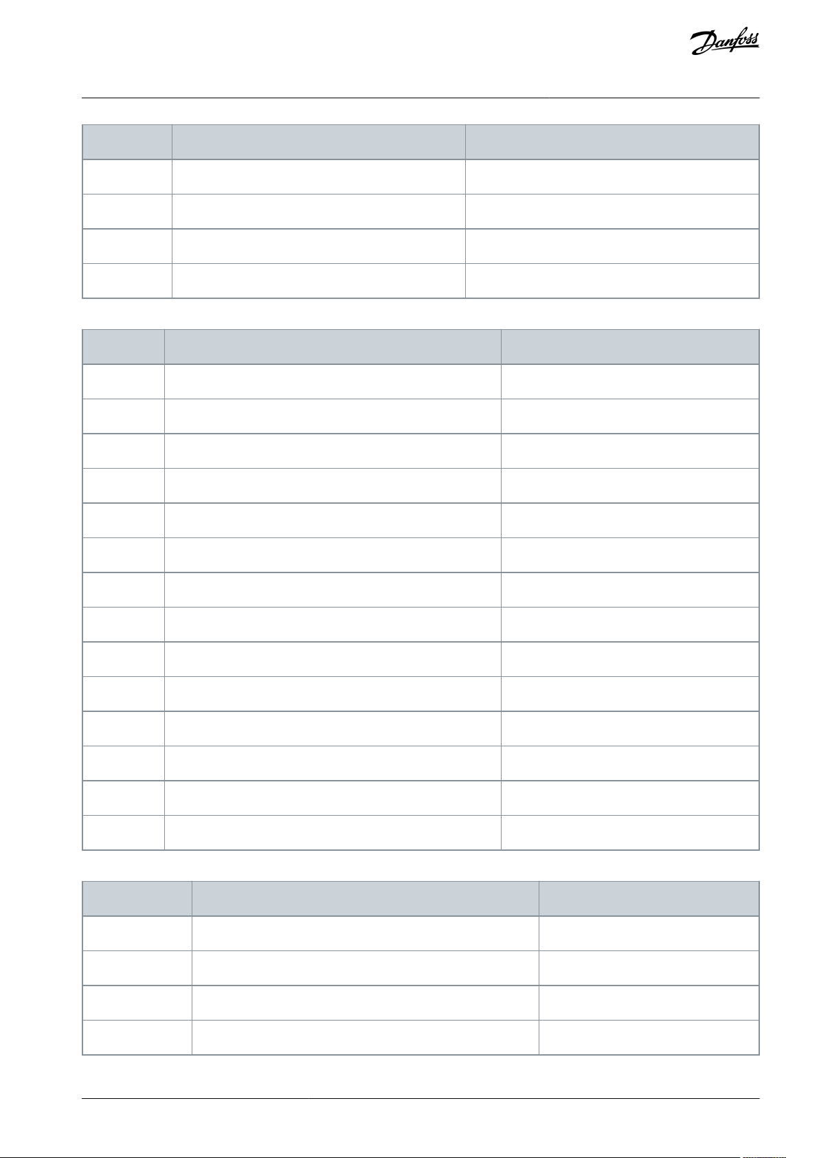
Bit
DIN StatusWord 1
DIN StatusWord 2
b12
DIN: C.1
DIN: E.5
b13
DIN: C.2
DIN: E.6
b14
DIN: C.3
b15
DIN: C.4
Bit
Fault
Comment
b0
Overcurrent or IGBT
F1, F31, F41
b1
Overvoltage
F2b2Undervoltage
F9b3Motor stalled
F15b4Earth fault
F3b5Motor underload
F17b6Drive overtemperature
F14b7Motor overtemperature
F16, F56, F29, F65
b8
Input phase
F10
b11
Keypad or PC control
F52
b12
Fieldbus
F53
b13
SystemBus
F59
b14
Slot
F54
b15
4 mA
F50
Bit
Fault
Comment
b2
Encoder
F43
b4
-
-
b6
External
F51b9IGBT
F31, F41
VACON® NX All-in-One
Application Guide
Table 49: Fault Word 1, ID1172
Multi-purpose Control Application
Table 50: Fault Word 2, ID1173
AB296635287482en-000201 / DPD00903 | 87Danfoss A/S © 2020.12
Page 88
Bit
Fault
Comment
b10
Brake
F58
b14
Main switch open
F64
b15
-
-
Bit
Warning
Comment
b0
Motor stalled
W15b1Motor overtemperature
W16, W29, W56, W65
b2
Motor underload
W17b3Input phase loss
W10b4Output phase loss
W11b8Drive overtemperature warning
W14b9Analog input < 4 mA
W50
b10
Not used
-
b13
Not used
-
b14
Mechanical brake
W58
b15
Keypad or PC Fault/Warning
W52
Bit
False
True
b0-Reserved
b1-Drive 1 Ready
b2-Drive 1 Running
b3-Drive 1 Fault
b4-Reserved
b5-Drive 2 Ready
b6-Drive 2 Running
b7-Drive 2 Fault
VACON® NX All-in-One
Application Guide
Table 51: Alarm Word 1, ID1174
Multi-purpose Control Application
Table 52: SystemBus Status Word, ID1601
AB296635287482en-000201 / DPD0090388 | Danfoss A/S © 2020.12
Page 89

Bit
False
True
b8-Reserved
b9-Drive 3 Ready
b10-Drive 3 Running
b11-Drive 3 Fault
b12-Reserved
b13-Drive 4 Ready
b14-Drive 4 Running
b15-Drive 4 Fault
Bit
False
Trueb0Flux not ready
Flux ready (>90%)
b1
Not in Ready state
Ready
b2
Not running
Running
b3
No fault
Fault
b4-Charge switch state
b5
-
-
b6
Run disabled
Run enable
b7
No warning
Warning
b8
-
-b9-
-
b10
-
-
b11
No DC brake
DC brake is active
b12
No run request
Run request
b13
No limit controls active
Limit control active
b14
External brake control OFF
External brake control ON
b15-Heartbeat
VACON® NX All-in-One
Application Guide
Table 53: Follower Drive Status Word
Multi-purpose Control Application
AB296635287482en-000201 / DPD00903 | 89Danfoss A/S © 2020.12
Page 90

Status
Word
Standard Application
Local/Remote
Control Application
Multi-Step
Control Application
PID Control Application
Multi-Purpose Control Application
Pump and Fan
Control Application
b0
----Flux Ready
-
b1
Ready
Ready
Ready
Ready
Ready
Ready
b2
Run
Run
Run
Run
Run
Runb3Fault
Fault
Fault
Fault
Fault
Fault
b4
----At Reference
-
b5
---
No EMStop (VACON® NXP)
-
-
b6
Run Enable
Run Enable
Run Enable
Run Enable
Run Enable
Run Enable
b7
Warning
Warning
Warning
Warning
Warning
Warning
b8
----At Zero Speed
-b9----Start Delay
-
b10
----Torque Control
Speed Limit Active
b11
DC Brake
DC Brake
DC Brake
DC Brake
DC Brake
DC Brake
b12
Run request
Run request
Run request
Run request
Run request
Run request
b13
Limit control
Limit control
Limit control
Limit control
Limit control
Limit control
b14
---
-
Brake control
Aux 1
b15-Place B is active
-
PID active
-
Aux 2
Index
Parameter
Min
Max
Unit
Default
ID
Description
P2.1.1
Min frequency
0.00
P2.1.2
Hz
0.00
101-P2.1.2
Max frequency
P2.1.1
320.00
Hz
50.00
102-P2.1.3
Acceleration time 1
0.1
3000.0
s
3.0
103-P2.1.4
Deceleration time 1
0.1
3000.0
s
3.0
104
-
VACON® NX All-in-One
Application Guide
Multi-purpose Control Application
Application Status Word combines different drive statuses to one data word (see Monitoring Value V1.21.4 Status Word). Status
Word is visible on keypad in Multi-Purpose application only. The Status Word of any other application can be read with the VACON
NCDrive PC software.
Table 54: Application Status Word Content
®
7.4.2 Basic Parameters (Control Panel: Menu M2 -> G2.1)
Table 55: Basic Parameters G2.1
AB296635287482en-000201 / DPD0090390 | Danfoss A/S © 2020.12
Page 91

Index
Parameter
Min
Max
Unit
Default
ID
Description
P2.1.5
Current limit
Varies
Varies
A
0.00
107
-
P2.1.6
(1)
Nominal voltage of the motor
180
690VNX2: 230 V
NX5: 400 V
NX6: 690 V
110
-
P2.1.7
(1)
Nominal frequency of the motor
8.00
320.00
Hz
50.00
111
-
P2.1.8
(1)
Nominal speed of the motor
24
20 000
RPM
1440
112
-
P2.1.9
(1)
Nominal current of the motor
Varies
Varies
A
5.40
113
-
P2.1.10
Motor cos phi
0.30
1.00-0.85
120
-
P2.1.11
I/O reference
0
15/16
-
0
117
0 = AI1
1 = AI2
2 = AI1+AI2
3 = AI1-AI2
4 = AI2-AI1
5 = AI1xAI2
6 = AI1 Joystick
7 = AI2 Joystick
8 = Keypad
9 = Fieldbus
10 = Motor potentiometer
11 = AI1, AI2 minimum
12 = AI1, AI2 maximum
13 = Max frequency
14 = AI1/AI2 selection
15 = Encoder 1
16 = Encoder 2 (VACON® NXP only)
P2.1.12
Keypad control reference
0
9-8
121
0 = AI1
1 = AI2
2 = AI1+AI2
3 = AI1-AI2
4 = AI2-AI1
5 = AI1xAI2
6 = AI1 Joystick
7 = AI2 Joystick
8 = Keypad
9 = Fieldbus
P2.1.13
Fieldbus control reference
0
9-9
122
P2.1.14
Jogging speed refrerence
0.00
P2.1.2
Hz
5.00
124
See 10.157 (ID 413) Jogging Speed
P2.1.15
Preset speed 1
0.00
P2.1.2
Hz
10.00
105-P2.1.16
Preset speed 2
0.00
P2.1.2
Hz
15.00
106-P2.1.17
Preset speed 3
0.00
P2.1.2
Hz
20.00
126
-
VACON® NX All-in-One
Application Guide
Multi-purpose Control Application
AB296635287482en-000201 / DPD00903 | 91Danfoss A/S © 2020.12
Page 92

Index
Parameter
Min
Max
Unit
Default
ID
Description
P2.1.18
Preset speed 4
0.00
P2.1.2
Hz
25.00
127-P2.1.19
Preset speed 5
0.00
P2.1.2
Hz
30.00
128-P2.1.20
Preset speed 6
0.00
P2.1.2
Hz
40.00
129-P2.1.21
Preset speed 7
0.00
P2.1.2
Hz
50.00
130
-
Index
Parameter
Min
Max
Unit
Default
ID
Description
P2.2.1.1
(1)
Start/Stop logic
0
7-0
300
Logic = 0
Ctrl sgn 1 = Start forward
Ctrl sgn 2 = Start reverse
Logic = 1
Ctrl sgn1 = Start/ Stop
Ctrl sgn 2 = Reverse
Logic = 2
Ctrl sgn 1 = Start/ Stop
Ctrl sgn 2 = Run enable
Logic = 3
Ctrl sgn 1 = Start pulse (edge)
Ctrl sgn 2 = Stop pulse
Logic = 4
Ctrl sgn 1 = Start
Ctrl sgn 2 = Motor potentiometer UP
Logic = 5
Ctrl sgn 1 = Forward pulse (edge)
Ctrl sgn 2 = Reverse pulse (edge)
Logic = 6
Ctrl sgn 1 = Start pulse (edge)
Ctrl sgn 2 = Reverse pulse
Logic = 7
Ctrl sgn 1 = Start pulse (edge)
Ctrl sgn 2 = Enable pulse
P2.2.1.2
(1)
Motor potentiometer ramp time
0.1
2000.0
Hz/s
10.0
331
-
P2.2.1.3
(1)
Motor potentiometer frequency reference memory reset
0
2-1
367
0 = No reset
1 = Reset if stopped or powered down
2 = Reset if powered down
P2.2.1.4
(1)
Adjust input
0
5-0
493
0 = Not used
1 = AI1
2 = AI2
3 = AI3
4 = AI4
VACON® NX All-in-One
Application Guide
1
Parameter value can only be changed after the AC drive has been stopped.
7.4.3 Input Signals
Table 56: Basic Settings (Control Panel: Menu M2 -> G2.2.1)
Multi-purpose Control Application
AB296635287482en-000201 / DPD0090392 | Danfoss A/S © 2020.12
Page 93

Index
Parameter
Min
Max
Unit
Default
ID
Description
5 = Fieldbus (see group G2.9)
P2.2.1.5
Adjust minimum
0.0
100.0
%
0.0
494-P2.2.1.6
Adjust maximum
0.0
100.0
%
0.0
495
-
Index
Parameter
Min
Max
Unit
Default
ID
Description
P2.2.2.1
(1)
AI1 signal selection
0.1
E.10-A.1
377
-
P2.2.2.2
AI1 filter time
0.00
320.00
s
0.10
324
P2.2.2.3
(2)
AI1 signal range
0
3-0
320
0 = 0–10 V (0–20 mA)
1 = 2–10 V (4–20 mA)
2 = -10V...+10 V
3 = Custom range
P2.2.2.4
AI1 custom minimum setting
-160.00
160.00
%
0.00
321-P2.2.2.5
AI1 custom maximum setting
-160.00
160.00
%
100.00
322-P2.2.2.6
AI1 reference scaling, minimum value
0.00
320.00
Hz
0.00
303
-
P2.2.2.7
AI1 reference scaling, maximum value
0.00
320.00
Hz
0.00
304
-
P2.2.2.8
AI1 joystick hysteresis
0.00
20.00
%
0.00
384
-
P2.2.2.9
AI1 sleep limit
0.00
100.00
%
0.00
385
-
P2.2.2.10
AI1 sleep delay
0.00
320.00
s
0.00
386
-
P2.2.2.11
AI1 joystick offset
-100.00
100.00
%
0.00
165
-
Index
Parameter
Min
Max
Unit
Default
ID
Description
P2.2.3.1
(1)
AI2 signal selection
0.1
E.10-A.2
388
-
P2.2.3.2
AI2 filter time
0.00
320.00
s
0.10
329
-
P2.2.3.3
(2)
AI2 signal range
0
3-1
325
0 = 0–10 V (0-20mA)
1 = 2–10 V (4–20 mA)
2 = -10V...+10 V
3 = Custom range
VACON® NX All-in-One
Application Guide
1
Parameter value can only be changed after the AC drive has been stopped.
Table 57: Analog Input 1 (Control Panel: Menu M2 -> G2.2.2)
Multi-purpose Control Application
1
Use the Terminal to Function method (TTF) with these parameters, see 10.619 "Terminal to Function" (TTF) Programming Principle)
2
Remember to place jumpers of block X2 according to the selection (0, 1, 2, or 3). See the User Manual of the product.
Table 58: Analog Input 2 (Control Panel: Menu M2 -> G2.2.3)
AB296635287482en-000201 / DPD00903 | 93Danfoss A/S © 2020.12
Page 94

Index
Parameter
Min
Max
Unit
Default
ID
Description
P2.2.3.4
AI2 custom minimum setting
-160.00
160.00
%
20.00
326-P2.2.3.5
AI2 custom maximum setting
-160.00
160.00
%
100.00
327-P2.2.3.6
AI2 reference scaling, minimum value
0.00
320.00
Hz
0.00
393
-
P2.2.3.7
AI2 reference scaling, maximum value
0.00
320.00
Hz
0.00
394
-
P2.2.3.8
AI2 joystick hysteresis
0.00
20.00
%
0.00
395
-
P2.2.3.9
AI2 sleep limit
0.00
100.00
%
0.00
396
-
P2.2.3.10
AI2 sleep delay
0.00
320.00
s
0.00
397
-
P2.2.3.11
AI2 joystick offset
-100.00
100.00
%
0.00
166
-
Index
Parameter
Min
Max
Unit
Default
ID
Description
P2.2.4.1
(1)
AI3 signal selection
0.1
E.10-0.1
141
-
P2.2.4.2
AI3 filter time
0.00
320.00
s
0.00
142
0 = No filtering
P2.2.4.3
(2)
AI3 signal range
0
3-0
143
0 = 0–10 V (0-20mA)
1 = 2–10 V (4–20 mA)
2 = -10V...+10 V
3 = Custom range
P2.2.4.4
AI3 custom minimum setting
-160.00
160.00
%
0.00
144-P2.2.4.5
AI3 custom maximum setting
-160.00
160.00
%
100.00
145
-
P2.2.4.6
AI3 signal inversion
0
1-0
151
0 = Not inverted
1 = Inverted
Index
Parameter
Min
Max
Unit
Default
ID
Description
P2.2.5.1
(1)
AI4 signal selection
0.1
E.10-0.1
152
-
P2.2.5.2
AI4 filter time
0.00
320.00
s
0.00
153
0 = No filtering
P2.2.5.3
(2)
AI4 signal range
0
3-1
154
0 = 0–10 V (0-20mA)
1 = 2–10 V (4–20 mA)
2 = -10V...+10 V
VACON® NX All-in-One
Application Guide
1
Use the Terminal to Function method (TTF) with these parameters, see
2
Remember to place jumpers of block X2 according to the selection (0, 1, 2 or 3). See the User Manual of the product.
10.619 "Terminal to Function" (TTF) Programming Principle)
Multi-purpose Control Application
Table 59: Analog Input 3 (Control Panel: Menu M2 -> G2.2.4)
1
Use the Terminal to Function method (TTF) with these parameters, see
2
Remember to place jumpers of block X2 according to the selection (0, 1, 2 or 3). See the User Manual of the product.
Table 60: Analog Input 4 (Control Panel: Menu M2 -> G2.2.5)
10.619 "Terminal to Function" (TTF) Programming Principle)
AB296635287482en-000201 / DPD0090394 | Danfoss A/S © 2020.12
Page 95

Index
Parameter
Min
Max
Unit
Default
ID
Description
3 = Custom range
P2.2.5.4
AI4 custom minimum setting
-160.00
160.00
%
20.00
155-P2.2.5.5
AI4 custom maximum setting
-160.00
160.00
%
100.00
156
-
P2.2.5.6
AI4 signal inversion
0
1-0
162
0 = Not inverted
1 = Inverted
Index
Parameter
Min
Max
Unit
Default
ID
Description
P2.2.6.1
Scaling of current limit
0
5-0
399
0 = Not used
1= AI1
2 = AI2
3 = AI3
4 = AI4
5 = FB Limit Scaling See group G2.9
P2.2.6.2
Scaling of DCbraking current
0
5-0
400
P2.2.6.3
Scaling of acc./ dec. times
0
5-0
401
P2.2.6.4
Scaling of torque supervision limit
0
5-0
402
P2.2.6.5
Scaling of torque limit
0
5-0
485
VACON® NXP drives only
P2.2.6.6
Scaling of generator torque limit
0
5-0
1087
As parameter P2.2.6.1
P2.2.6.7
Scaling of motoring power limit
0
5-0
179
P2.2.6.8
Scaling of generator power limit
0
5-0
1088
Index
Parameter
Min
Default
ID
Description
P2.2.7.1
(1)
Start signal 1
0.1
A.1
403
See P2.2.1.1.
P2.2.7.2
(1)
Start signal 2
0.1
A.2
404
See P2.2.1.1.
P2.2.7.3
(1)
Run enable
0.1
0.2
407
-
P2.2.7.4
(1)
Reverse
0.1
0.1
412
-
P2.2.7.5
(1)
Preset speed 1
0.1
0.1
419
See preset speeds in Basic Parameters (G2.1).
P2.2.7.6
(1)
Preset speed 2
0.1
0.1
420
P2.2.7.7
(1)
Preset speed 3
0.1
0.1
421
P2.2.7.8
(1)
Motor potentiometer reference DOWN
0.1
0.1
417
-
VACON® NX All-in-One
Application Guide
1
Use the Terminal to Function method (TTF) with these parameters, see 10.619 "Terminal to Function" (TTF) Programming Principle)
2
Remember to place jumpers of block X2 according to the selection (0, 1, 2 or 3). See the User Manual of the product.
Table 61: Free Analog Input, Signal Selection (Control Panel: Menu M2 -> G2.2.6
Multi-purpose Control Application
Table 62: Digital Inputs (Control Panel: Menu M2 -> G2.2.4)
AB296635287482en-000201 / DPD00903 | 95Danfoss A/S © 2020.12
Page 96

Index
Parameter
Min
Default
ID
Description
P2.2.7.9
(1)
Motor potentiometer reference UP
0.1
0.1
418
-
P2.2.7.10
(1)
Fault reset
0.1
A.3
414
-
P2.2.7.11
(1)
External fault (close)
0.1
A.5
405
-
P2.2.7.12
(1)
External fault (open)
0.1
0.2
406
-
P2.2.7.13
(1)
Acc/Dec time selection
0.1
A.6
408
-
P2.2.7.14
(1)
Acc/Dec prohibit
0.1
0.1
415
-
P2.2.7.15
(1)
DC braking
0.1
0.1
416
-
P2.2.7.16
(1)
Jogging speed
0.1
A.4
413
-
P2.2.7.17
(1)
AI1/AI2 selection
0.1
0.1
422
-
P2.2.7.18
(1)
Control from I/O terminal
0.1
0.1
409
-
P2.2.7.19
(1)
Control from keypad
0.1
0.1
410
-
P2.2.7.20
(1)
Control from fieldbus
0.1
0.1
411
-
P2.2.7.21
(1)
Parameter set 1/set 2 selection
0.1
0.1
496
-
P2.2.7.22
(1)
Motor control mode 1/2
0.1
0.1
164
-
VACON® NXP drives only
P2.2.7.23
(1)
Cooling monitor
0.1
0.2
750
-
P2.2.7.24
(1)
External brake acknowledge
0.1
0.2
1210
-
P2.2.7.26
(1)
Enable inching
0.1
0.1
532
-
P2.2.7.27
(1)
Inching reference 1
0.1
0.1
530
-
P2.2.7.28
(1)
Inching reference 2
0.1
0.1
531
-
P2.2.7.29
(1)
Reset encoder counter
0.1
0.1
1090
-
P2.2.7.30
(1)
Emergency stop
0.1
0.2
1213
-
P2.2.7.31
(1)
Master Follower mode 2
0.1
0.1
1092
See 10.612 Master/Follower Function and parameters P2.11.1–P2.11.7.
P2.2.7.32
(1)
Input switch acknowledgement
0.1
0.2
1209
-
P2.2.7.33
(1)
Active filter fault input
0.1
0.1
214
-
VACON® NX All-in-One
Application Guide
Multi-purpose Control Application
1
Use the Terminal to Function method (TTF) with these parameters, see
10.619 "Terminal to Function" (TTF) Programming Principle)
AB296635287482en-000201 / DPD0090396 | Danfoss A/S © 2020.12
Page 97

Index
Parameter
Min
Max
Unit
Default
ID
Description
P2.3.1.1
(1)
Digital output 1 signal selection
0.1
E.10-0.1
486
-
P2.3.1.2
Digital output 1 function
0
29-1
312
0 = Not used
1 = Ready
2 = Run
3 = Fault
4 = Fault inverted
5 = AC drive overheat warning
6 = Ext. fault or warning
7 = Ref. fault or warning
8 = Warning
9 = Reverse
10 = Jogging spd selected
11 = At speed
12 = Mot. regulator active
13 = Freq. limit 1 superv.
14 = Freq. limit 2 superv.
15 = Torque limit superv.
16 = Ref. limit supervision
17 = External brake control
18 = I/O control place act.
19 = AC drive temp. limit superv.
20 = Reference inverted
21 = Ext. brake control inverted
22 = Therm. fault or warn.
23 = On/Off control
24 = Fieldbus DIN 1
25 = Fieldbus DIN 2
26 = Fieldbus DIN 3
27 = Temp.Warning
P2.3.1.2
Digital output 1 function
0
29-1
312
VACON® NXS drives only:
28 = Temp.Fault
VACON® NXP drives only:
29 = ID.Bit
P2.3.1.3
Digital output 1 on delay
0.00
320.00
Varies
0.00
487
-
P2.3.1.4
Digital output 1 off delay
0.00
320.00
Varies
0.00
488
-
VACON® NXP drives only
P2.3.1.5
INV Delayed DO1
0
1-0
1587
0 = No
1 = Yes
P2.3.1.6
ID Bit Free DO1
0.0
200.15
-
0.0
1217
-
VACON® NX All-in-One
Application Guide
cc = closing contact
oc = opening contact
7.4.4 Output Signals
Table 63: Delayed Digital Output 1 (Control Panel: Menu M2 -> G2.3.1)
Multi-purpose Control Application
AB296635287482en-000201 / DPD00903 | 97Danfoss A/S © 2020.12
Page 98

Index
Parameter
Min
Max
Unit
Default
ID
Description
P2.3.1.7
DO1 Time Scale
02-01060
0 = s
1 = min
2 = h
Index
Parameter
Min
Max
Unit
Default
ID
Description
P2.3.2.1
Digital output 2 signal selection
0.1
E.10-0.1
489
-
P2.3.2.2
Digital output 2 function
0
29-0
490
See P2.3.1.2
P2.3.2.3
Digital output 2 on delay
0.00
320.00
Varies
0.00
491
-
P2.3.2.4
Digital output 2 off delay
0.00
320.00
Varies
0.00
492
-
VACON® NXP drives only
P2.3.2.5
INV Delayed DO2
0
1-0
1588
0 = No
1 = Yes
P2.3.2.6
ID Bit Free DO2
0.0
200.15
-
0.0
1385
-
P2.3.2.7
DO2 Time Scale
02-01061
0 = s
1 = min
2 = h
Index
Parameter
Min
Default
ID
Description
N O T I C E
To avoid function overruns and to ensure flawless operation, make ABSOLUTELY sure that two functions ARE NOT CONNEC-
TED to one and same output.
P2.3.3.1
(1)
Ready
0.1
A.1
432
-
P2.3.3.2
(1)
Run
0.1
B.1
433
-
P2.3.3.3
(1)
Fault
0.1
B.2
434
-
P2.3.3.4
(1)
Inverted fault
0.1
0.1
435
-
P2.3.3.5
(1)
Warning
0.1
0.1
436
-
P2.3.3.6
(1)
External fault
0.1
0.1
437
-
P2.3.3.7
(1)
Reference fault/warning
0.1
0.1
438
-
VACON® NX All-in-One
Application Guide
1
Use the Terminal to Function method (TTF) with these parameters, see 10.619 "Terminal to Function" (TTF) Programming Principle.
Table 64: Delayed Digital Output 2 (Control Panel: Menu M2 -> G2.3.2)
Multi-purpose Control Application
Table 65: Digital Output Signals (Control Panel: Menu M2 -> G2.2.4)
AB296635287482en-000201 / DPD0090398 | Danfoss A/S © 2020.12
Page 99

Index
Parameter
Min
Default
ID
Description
P2.3.3.8
(1)
Overtemperature warning
0.1
0.1
439
-
P2.3.3.9
(1)
Reverse
0.1
0.1
440
-
P2.3.3.10
(1)
Unrequested direction
0.1
0.1
441
-
P2.3.3.11
(1)
At speed
0.1
0.1
442
-
P2.3.3.12
(1)
Jogging speed
0.1
0.1
443
-
P2.3.3.13
(1)
I/O control place
0.1
0.1
444
-
P2.3.3.14
(1)
External brake control
0.1
0.1
445
See 10.189 (ID 445) External Brake Control and
10.190 (ID 446) External Brake Control, Inverted.
P2.3.3.15
(1)
External brake control, inverted
0.1
0.1
446
P2.3.3.16
(1)
Output frequency limit 1 supervision
0.1
0.1
447
See 10.75 (ID 315) Output Frequency Limit Supervi-
sion Function
P2.3.3.17
(1)
Output frequency limit 2 supervision
0.1
0.1
448
See 10.104 (ID 346) Output Frequency Limit 2 Su-
pervision Function.
P2.3.3.18
(1)
Reference limit supervision
0.1
0.1
449
See 10.108 (ID 350) Reference Limit, Supervision
Function.
P2.3.3.19
(1)
Temperature limit supervision
0.1
0.1
450
See 10.112 (ID 354) Frequency Converter Tempera-
ture Limit Supervision.
P2.3.3.20
(1)
Torque limit supervision
0.1
0.1
451
See 10.106 (ID 348) Torque Limit, Supervision Func-
tion.
P2.3.3.21
(1)
Thermistor fault or warning
0.1
0.1
452
-
P2.3.3.22
(1)
Analog input supervision limit
0.1
0.1
453
See 10.114 (ID 356) Analog Supervision Signal.
P2.3.3.23
(1)
Motor regulator activation
0.1
0.1
454
-
P2.3.3.24
(1)
Fieldbus DIN 1
0.1
0.1
455
-
P2.3.3.25
(1)
Fieldbus DIN 2
0.1
0.1
456
-
P2.3.3.26
(1)
Fieldbus DIN 3
0.1
0.1
457
-
P2.3.3.27
(1)
Fieldbus DIN 4
0.1
0.1
169
-
P2.3.3.28
(1)
Fieldbus DIN 5
0.1
0.1
170
-
VACON® NXP drives only
P2.3.3.29
(1)
DC ready pulse
0.1
0.1
1218
-
VACON® NX All-in-One
Application Guide
Multi-purpose Control Application
AB296635287482en-000201 / DPD00903 | 99Danfoss A/S © 2020.12
Page 100

Index
Parameter
Min
Default
ID
Description
P2.3.3.30
(1)
Safe Disable Active
0.1
0.1
756
-
Index
Parameter
Min
Max
Unit
Default
ID
Description
P2.3.4.1
Output frequency limit 1 supervision
0
3-0
315
0 = No supervision
1 = Low limit supervision
2 = High limit supervision
3 = Brake-on control
P2.3.4.2
Output frequency limit 1; Supervised value
0.00
320.00
Hz
0.00
316
-
P2.3.4.3
Output frequency limit 2 supervision
0
4-0
346
0 = No supervision
1 = Low limit supervision
2 = High limit supervision
3 = Brake-off control
4 = Brake on/off control
P2.3.4.4
Output frequency limit 2; Supervised value
0.00
320.00
Hz
0.00
347
-
P2.3.4.5
Torque limit supervision
0
3-0
348
0 = No supervision
1 = Low limit supervision
2 = High limit supervision
3 = Brake-off control
P2.3.4.6
Torque limit supervision value
-300.0
300.0
%
100.0
349
-
P2.3.4.7
Reference limit supervision
0
2-0
350
0 = No supervision
1 = Low limit
2 = High limit
P2.3.4.8
Reference limit supervision value
0.0
100.0
%
0.0
351
0.0 = Min frequency
100.0 = Max frequency
P2.3.4.9
External brake-off delay
0.0
100.0
s
0.5
352-P2.3.4.10
External brake-on delay
0.0
100.0
s
1.5
353
-
P2.3.4.11
Temperature limit supervision
0
2-0
354
0 = No supervision
1 = Low limit
2 = High limit
P2.3.4.12
Temperature supervised value
-10
100°C40
355
-
P2.3.4.13
Analog supervision signal
0
4-0
356
0 = Not used
1 = AI1
2 = AI2
3 = AI3
4 = AI4
VACON® NX All-in-One
Application Guide
1
Use the Terminal to Function method (TTF) with these parameters, see 10.619 "Terminal to Function" (TTF) Programming Principle)
Table 66: Limit Settings (Control Panel: Menu M2 -> G2.3.4)
Multi-purpose Control Application
AB296635287482en-000201 / DPD00903100 | Danfoss A/S © 2020.12
 Loading...