

Page 1

VACON
CX/CXL/CXS
FREQUENCY CONVERTERS
Pump control
with autochange
Subject to changes without notice.
F O R S M O O T H C O N T R O L
Page 2

Page 2 Vacon
Pump and fan control with autochange
Pump control with
autochange
Application
(par. 0.1 = 0)
CONTENTS
1 General ........................................................... 3
2 Control I/O ...................................................... 3
3 Control signal logic ..........................................4
4 Parameter group 0 .......................................... 5
5 Basic parameters, Group 1 ............................. 6
5.1 Parameter table, Group 1........................6
5.2 Description of Group1 parameters .......... 7
6 Special parameters, Groups 2—10 ............... 10
6.1 Parameter tables, Groups
6.2
Description of Groups 2—10 param. .... 21
7 I/O-expander with pump and fan control.......... 59
8 Commissioning of pump and fan control......... 62
9 Monitoring data ............................................... 63
10 Panel reference .......................................... 64
2—10 .......... 10
Vacon Plc Phone: +358-201 2121 Fax:+358-201 212 205
Service: +358-40-8371 150 E-mail: vacon@vacon.com
Page 3
Vacon Page 3
Pump control with autochange
1 General
Pump and fan control with autochange can be
selected by setting the value of parameter 0.1
to 0.
The application can be used to control one
variable speed drive and 0-4 auxiliary drives.
Additionally the motor connected to the
frequency converter and the start order of the
auxiliary drives can be changed with the
autochange function and external relay
system. The PI-controller of the frequency
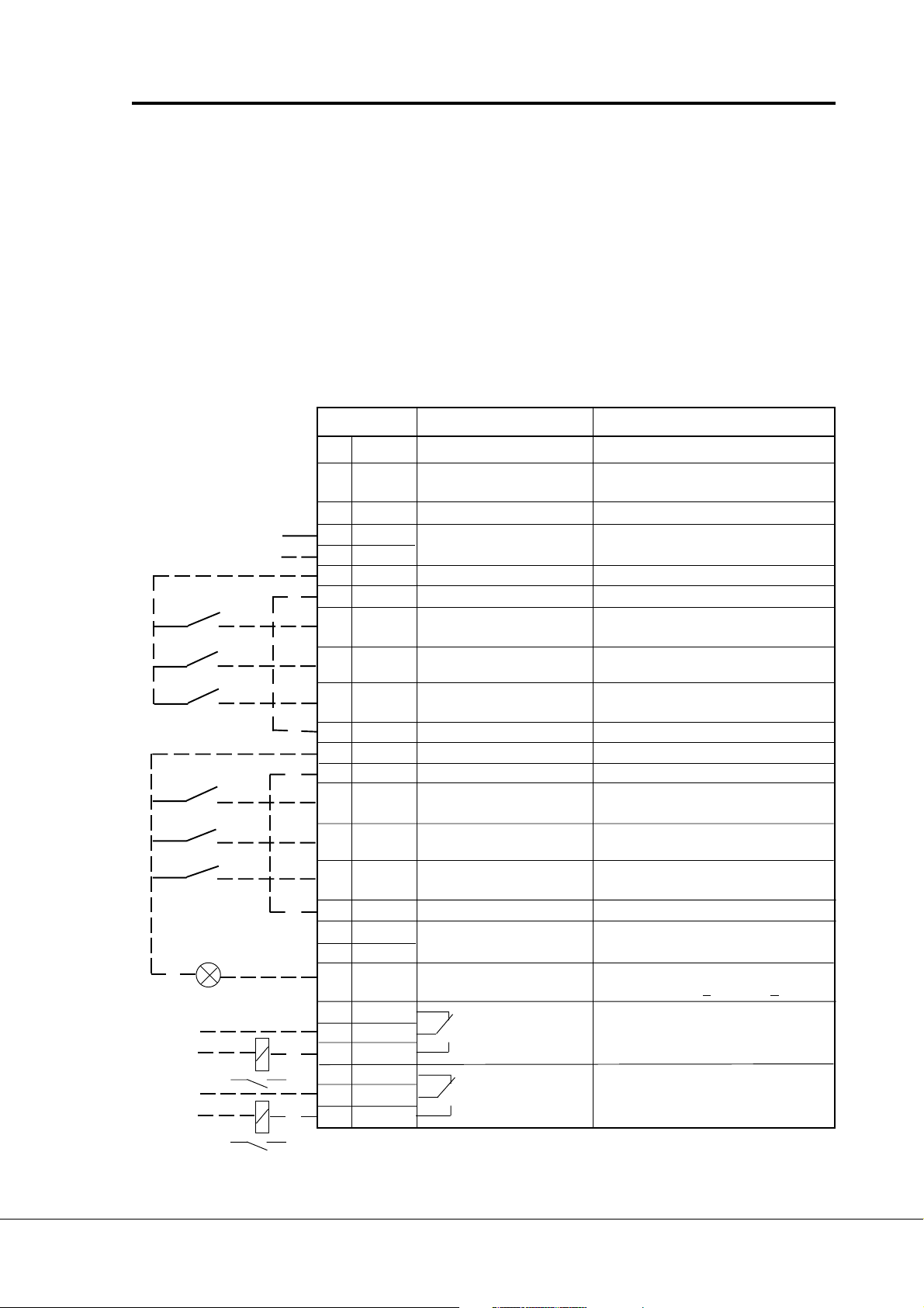
2 Control I/O
Terminal Signal Description
PI-controller
actual value
READY
220
VAC
220
VAC
FAULT
1 +10V
2Uin+ Analog input, voltage Programmable
3 GND I/O ground Ground for reference and controls
+ Analogue input, PI-controller actual value
4I
in
5Iin- current (programmable) range 4—20 mA
6 +24V Control voltage output Voltage for switches, etc. max. 0.1 A
7 GND Control voltage ground Ground for reference and controls
8 DIA1 Start/Stop Contact open = stop
9 DIA2 Interlock input, autoch. 1 Contact open = no interlock
10 DIA3 Interlock input, autoch. 2 Contact open = no interlock
11 CMA Common for DIA1—DIA3 Connect to GND or + 24V
12 +24V Control voltage output Voltage for switches, (same as #6)
13 GND I/O ground Ground for reference and controls
14 DIB4 Start/Stop Contact open = stop
15 DIB5 Jogging speed select Contact open = no action
16 DIB6 Source A/B selection Contact open = source A is active
17 CMB Common for DIB4—DIB6 Connect to GND or + 24V
18 I
out
19 I
out
20 DO1 Digital output Programmable ( par. 3. 6)
21 RO1 Relay output 1 Contact closed = control active
22 RO1 Autochange 1 Programmable ( par. 3. 7)
23 RO1 control
24 RO2 Relay output 2 Contact closed = control active
25 RO2 Autochange 2 Programmable ( par. 3. 8 )
26 RO2 control
Reference output Voltage for a potentiometer, etc.
ref
range 0—10 V DC (factory setting: not in use)
Source A (PI-controller) Contact closed = start
(programmable) Contact closed = interlock active
(programmable) Contact closed = interlock active
Source B (Direct freq. ref.) Contact closed = start
(programmable) Contact closed = jogging speed
+ Analogue output Programmable (par. 3. 1)
- Output frequency Range 0—20 mA/RL max. 500 Ω
FAULT Open collector, I<50 mA, U<48 VDC
converter controls the speed of the variable
speed drive and gives control signals to Start
and Stop auxiliary drives to control the total
flow.
The application has two control sources on
I/O terminals. Source A is Pump and fan
control and source B is direct frequency
reference. The control source is selected with
DIB6 input.
Note! Remember to connect CMA and CMB inputs
Contact closed = source B is active
Figure 2-1 Default I/O configuration and connection example of the Pump and fan
Control Application with autochange
Vacon Plc Phone: +358-201 2121 Fax:+358-201 212 205
Service: +358-40-8371 150 E-mail: vacon@vacon.com
E-mail: application.team@vacon.com
Page 4
Page 4 Vacon
Pump and fan control with autochange
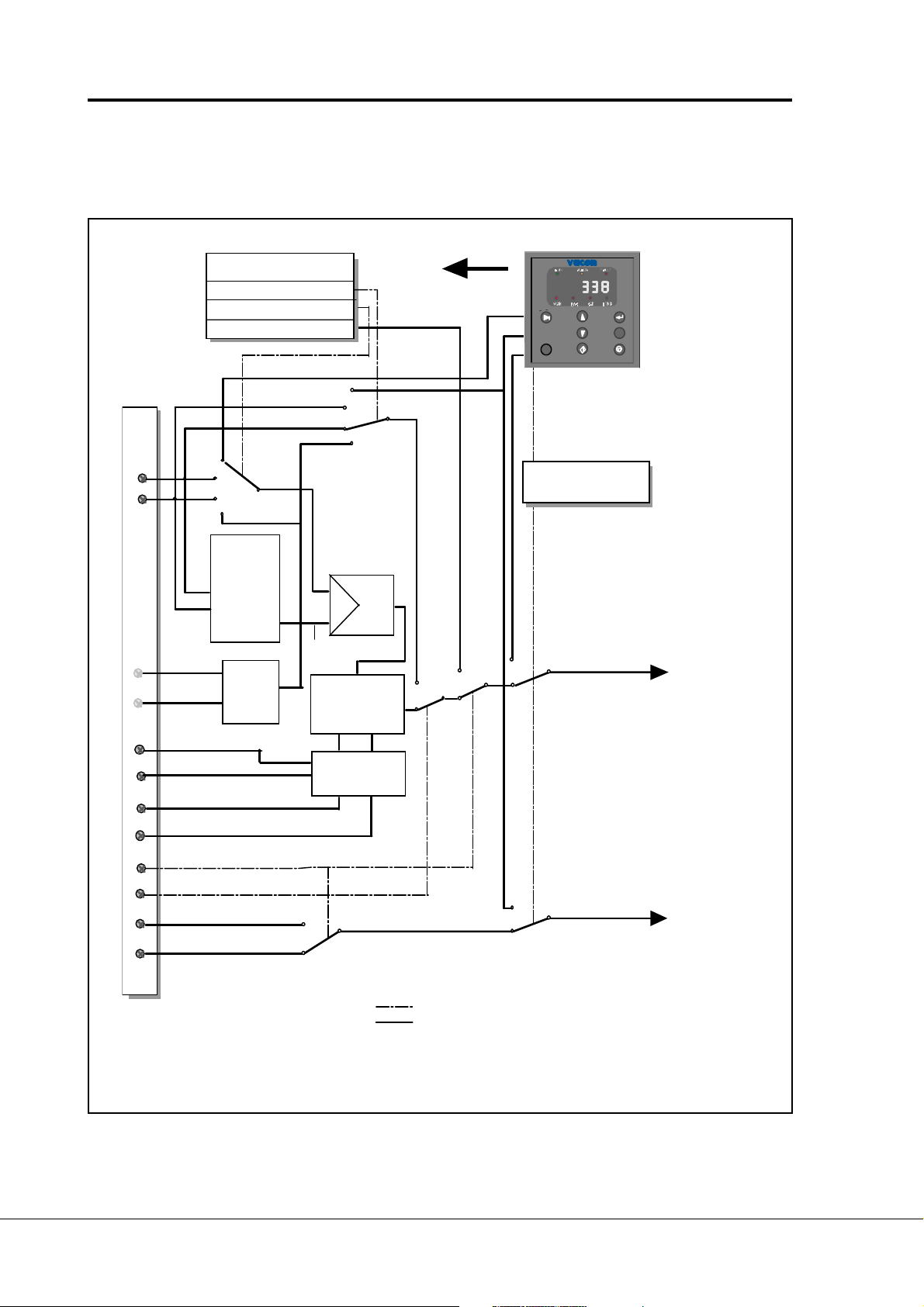
3 Control signal logic
The logic of I/O-control signals and push button signals from the panel are presented in the figure
3-1.
PARAMET ERS
2
26 Source B ref. select.
.
2
15 Source A ref. select.
.
4
12 Jogging speed ref.
.
PG
RST
Uin+
Iin–
Up
DIA2
Down
DIA3
DIA2
Interlock 1
DIA3
Interlock 2
Autochange 1
RO1
RO2
Autochange 2
DIB5
Jogging spe ed s
(Programmable)
DIB6
Source A/B select.
DIB4
Start/Stop, source B
DIA1
S tart/Stop, source A
Actual value
selec tion
Motorised
poten tiometer
reference
Freq. ref.,
Source B
Reference,
Source A
PI-controller
P
I
Actual
value
Calculation of
fre q . ref. a nd
control logic of
auxiliary drives
Autochange
lo gic
PROGRAMMABLE
PUSH-BUTTON 2
P
P
Internal
frequency
reference
Interna l
Start/Stop
control line
=
signal line
=
Figure 3-1 Control signal logic of the Pump and fan control Application.
Switch positions shown correspond to the factory settings.
Vacon Plc Phone: +358-201 2121 Fax:+358-201 212 205
Service: +358-40-8371 150 E-mail: vacon@vacon.com
pfcauto.fh3
Page 5

Vacon Page 5
Pump control with autochange
4 Parameter group 0
Number Parameter Range Step Default Customer Description
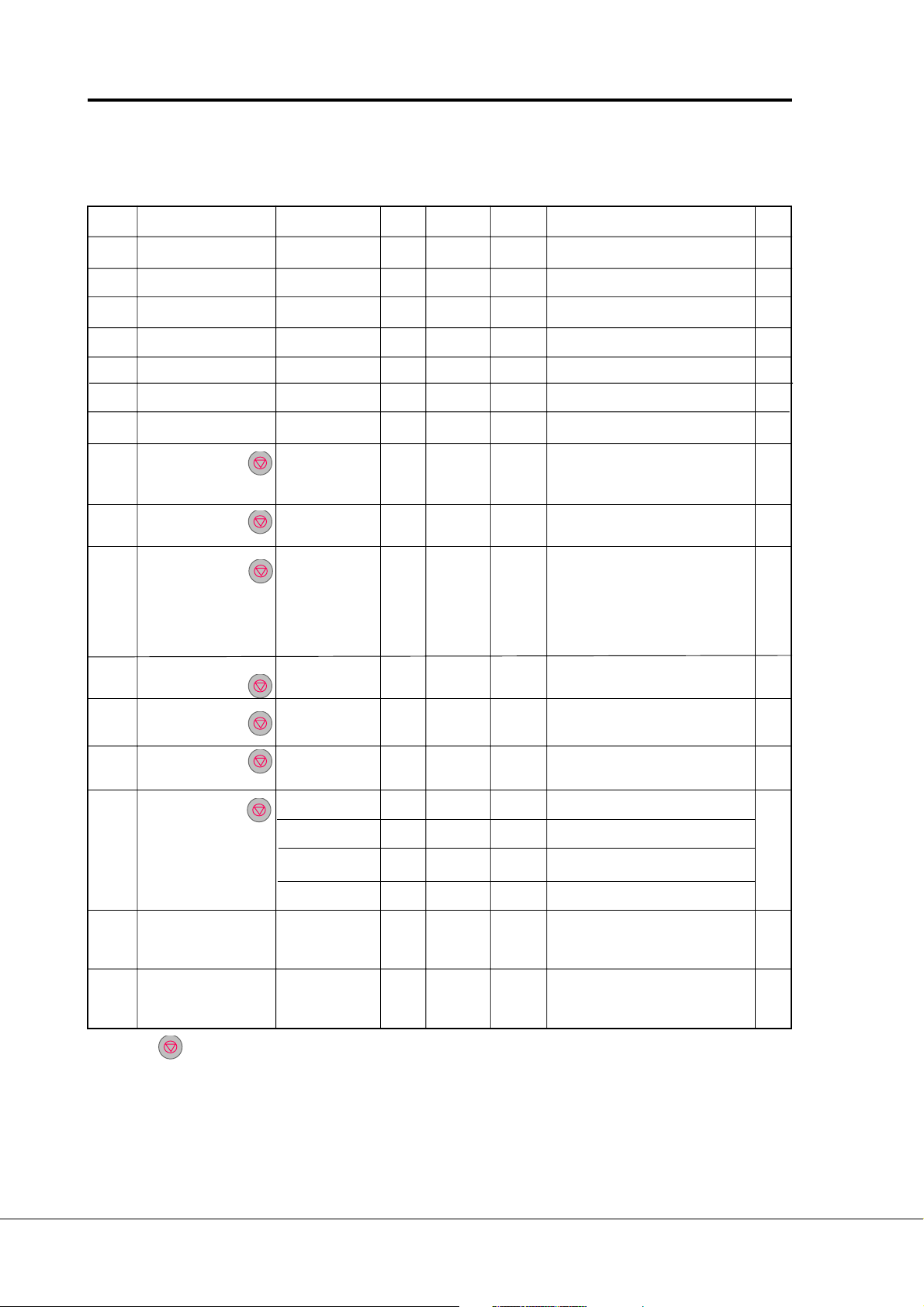
0. 1 Application 0— 7 1 0 0 = Pump and fan control with autoselection change (loaded special application)
1 = Basic Application
2 = Standard Application
3 = Local / Remote Control Application
4 = Multi-step Speed Application
5 = PI-control Application
6 = Multi-purpose Control Application
7 = Pump and fan control Application
0. 2 Parameter 0— 5 1 0 0 = Loading ready / Select loading
loading 1 = Load default setting
2 = Read up parameters to user's set
3 = Load down user's set parameters
4 = Read parameters up to the panel
(possible only with graphical panel)
5 = Load down parameters from panel
(possible only with graphical panel)
0.3 Language selection 0—1 1 0 0 = English
1 = Finnish
2= Spanish
0.1 Application selection
With this parameter the active application can be selected. If the device has been ordered
from the factory equipped with pump and fan control with autochange application this has
been loaded to the unit as application 0. The application has also been set active in the factory. Check anyway that the value of the parameter 0.1 is zero when you want to use the
pump and fan control with autochange application.
If the application is loaded to the device later it has to be set active always after loading
by setting the value of parameter 0.1 to zero.
0.2 Parameter loading
See User's manual chapter 11.
0.3 Language
With this parameter the language of the graphical panel can be selected.
Vacon Plc Phone: +358-201 2121 Fax:+358-201 212 205
Service: +358-40-8371 150 E-mail: vacon@vacon.com
E-mail: application.team@vacon.com
Page 6
Page 6 Vacon
Pump and fan control with autochange
5 Basic parameters, Group 1
5.1 Parameter table, Group 1
Code Parameter Range Step Default Custom Description Page
1. 1 Minimum frequency 0—120/500 Hz 1 Hz 10 Hz 6
1. 2 Maximum frequency 0—120/500 Hz 1 Hz 51 Hz *) 6
1. 3 Acceleration time 1 0.1—3000 s 0.1 s 1 s Time from f
1. 4 Deceleration time 1 0.1—3000 s 0.1 s 1 s Time from f
(1. 1) to f
min
(1. 2) to f
max
(1. 2) 6
max
(1. 1) 6
min
1. 5 PI-controller gain 0-1000% 1 % 100% 0= No P-part in use 6
1. 6 PI-controller I-time 0—320.00 s 0.01s 10,00s 0= No I-part in use 6
1. 7 Current limit 0.1—2.5 x I
0.1 A 1.5 x I
nCX
n CX
Output current limit [A] of the unit 6
1. 8 U/f ratio selection 0—2 1 0 0 = Linear 6
1 = Squared
2 = Programmable U/f ratio
1. 9 U/f optimization 0—1 1 0 0 = None 7
1 = Automatic torque boost
1. 10 Nominal voltage 180—690 1 V 230 V Vacon range CX/CXL2 8
of the motor 400 V Vacon range CX/CXL/CXS4
500 V Vacon range CX/CXL/CXS5
690 V Vacon range CX6
1. 11 Nominal frequency 30—500 Hz 1 Hz 50 Hz f
from the rating plate of 8
n
of the motor the motor
1. 12 Nominal speed 1—20000 rpm 1 rpm 1440 rpm n
from the rating plate of 8
n
of the motor **) the motor
1. 13 Nominal current 2.5 x I
of the motor( I
n Mot)
n CX
0.1 A I
nCX
In from the rating plate of 8
the motor
1. 14 Supply voltage 180—250 230 V Vacon range CX/CXL2 8
380—440 400 V Vacon range CX/CXL/CXS4
380—500 500 V Vacon range CX/CXL/CXS5
525—690 690 V Vacon range CX6
1. 15 Parameter conceal 0—1 1 0 Visibility of the parameters: 8
0 = All parameter groups visible
1 = Only group 1 is visible
1. 16 Parameter value lock 0—1 1 0 Disables parameter changes: 8
0 = Changes enabled
1 = Changes disabled
Note! =Parameter value can be changed
only when the frequency converter
is stopped.
*) If 1. 2 > motor synchr. speed, check suitability
for motor and drive system
Selecting 120 Hz/500 Hz range see page 6-5.
**) Default value for a four pole motor and a
nominal size frequency converter.
Table 5-1 Group 1 basic parameters.
Vacon Plc Phone: +358-201 2121 Fax:+358-201 212 205
Service: +358-40-8371 150 E-mail: vacon@vacon.com
Page 7

Vacon Page 7
Pump control with autochange
5.2 Description of Group 1 parameters
1. 1, 1. 2 Minimum / maximum frequency
Defines frequency limits of the frequency converter.
The default maximum value for parameters 1. 1 and 1. 2 is 120 Hz. By setting 1. 2 =
120 Hz when the device is stopped (RUN indicator not lit) parameters 1. 1 and 1. 2
are changed to 500 Hz. At the same time the panel reference resolution is changed
from 0.01 Hz to 0.1 Hz.
Changing the max. value from 500 Hz to 120 Hz is done by setting parameter 1. 2 =
119 Hz when the device is stopped.
NOTICE! Start frequency of the auxiliary drive is not conditional on maximum
frequency because in the application start frequency and stop frequency of the
auxiliary drives are scaled by the endower of the system.
1. 3, 1. 4 Acceleration time 1, deceleration time 1:
These limits correspond to the time required for the output frequency to accelerate
from the set minimum frequency (par. 1. 1) to the set maximum frequency
(par. 1. 2).
1. 5 PI-controller gain
This parameter defines the gain of the PI-controller.
If this parameter is set to 100%, a 10% change in error value causes the controller
output to change by 10.0 Hz.
If the parameter value is set to 0 the PI-controller operates as I-controller.
1. 6 PI-controller I-time
Defines the integration time of the PI-controller.
1. 7 Current limit
This parameter determines the maximum motor current from the frequency converter.
To avoid motor overloading set this parameter according to the rated current of the
motor.
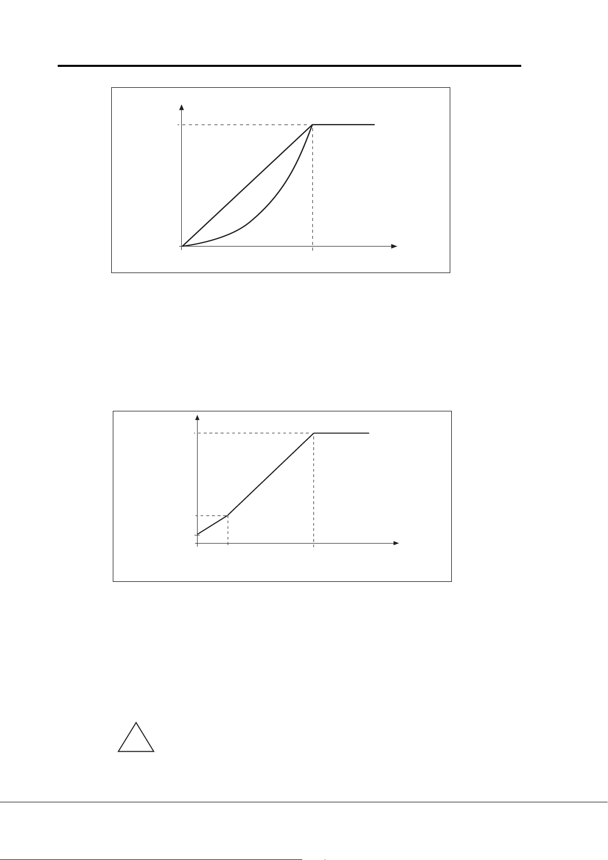
1. 8 U/f ratio selection
Linear: The voltage of the motor changes linearly with the frequency in
the constant flux area from 0 Hz to the field weakening point
0 (par. 6. 3) where the nominal voltage is supplied to the motor. See
figure 6.4-1.
Linear U/f ratio should be used in constant torque applications.
This default setting should be used if there is no special demand for another
setting.
Squared: The voltage of the motor changes following a squared curve form
with the frequency in the area from 0 Hz to the field weakening
1 point (par. 6. 3) where the nominal voltage is supplied to the motor.
See figure 6.4-1.
The motor runs undermagnetised below the field weakening point
and produces less torque and electromechanical noise. Squared U/f
ratio can be used in applications where torque demand of the load is
proportional to the square of the speed, e.g. in centrifugal fans and
pumps.
Vacon Plc Phone: +358-201 2121 Fax:+358-201 212 205
Service: +358-40-8371 150 E-mail: vacon@vacon.com
E-mail: application.team@vacon.com
Page 8
Page 8 Vacon
Un
(Par 6. 4)
Pump and fan control with autochange
U[V]
Default: nominal
voltage of the
motor
Linear
Field weakening
point
Squared
Default: nominal frequency
of the motor
(Par. 6. 3)
f[Hz]
UD009K07
Figure 6.4-1 Linear and squared U/f curves.
Programm. The U/f curve can be programmed with three different points.
U/f curve The parameters for programming are explained in the chapter 5.2.
2 The programmable U/f curve can be used if the other settings do not
satisfy the needs of the application. See figure 4-2.
U[V]
Un
Par 6. 4
Par. 6. 6
(Olet. 10%)
Par. 6. 7
(Olet. 1.3%)
Default: nominal
voltage of the
motor
Par. 6. 5
(Olet. 5 Hz)
Field weakening
point
Default: nominal frequency
of the motor
Par. 6. 3
f[Hz]
UD009K08
Figure 6.4-2 Programmable U/f curve.
1. 9 U/f optimization
Automatic The voltage to the motor changes automatically which makes the
torque motor to produce torque enough to start and run at low frequencies.
boost The voltage increase depends on the motor type and power.
Automatic torque boost can be used in applications where starting
torque is high due to starting friction, e.g. in conveyors.
NOTE! In high torque - low speed applications - it is likely the motor will
overheat. If the motor has to run a prolonged time under these
!
conditions, special attention must be paid to cooling the motor. Use
external cooling for the motor if the temperature tends to rise too high.
Vacon Plc Phone: +358-201 2121 Fax:+358-201 212 205
Service: +358-40-8371 150 E-mail: vacon@vacon.com
Page 9

Vacon Page 9
Pump control with autochange
1. 10 Nominal voltage of the motor
Find this value U
on the rating plate of the motor.
n
This parameter sets the Voltage at the field weakening point, parameter 6. 4, to
100% x U
n
motor
.
1. 11 Nominal frequency of the motor
Find this value f
on the rating plate of the motor.
n
This parameter sets the field weakening point, parameter 6. 3, to the
same value.
1. 12 Nominal speed of the motor
Find this value n
on the rating plate of the motor.
n
1. 13 Nominal current of the motor
Find this value I
on the rating plate of the motor.
n
1. 14 Supply voltage
Set parameter value according to the nominal voltage of the supply.
Values are pre-defined for CX/CXL2, CX/CXL/CXS4, CX/CXL/CXS5 and CX6
ranges, see table 6.4-1.
1. 15 Parameter conceal
Defines which parameter groups are available:
0 = All parameter groups are visible
1 = Only group 1 is visible
1. 16 Parameter value lock
Defines access to the changes of the parameter values:
0 = Parameter value changes enabled
1 = Parameter value changes disabled
Vacon Plc Phone: +358-201 2121 Fax:+358-201 212 205
Service: +358-40-8371 150 E-mail: vacon@vacon.com
E-mail: application.team@vacon.com
Page 10
Page 10 Vacon
Pump and fan control with autochange
6 Special parameters, Groups 2—9
6.1 Parameter tables
Group 2, Input signal parameters
Code Parameter Range Step Default Custom Description Page
2. 1 DIA2 function 0—10 1 11 0 = Not used 20
(terminal 9) 1 = Ext. fault, closing contact
2 = External fault, opening contact
3 = Run enable
4 = Acceler./deceler. time selection
5 = Reverse
6 = Jogging frequency
7 = Fault reset
8 = Acc./dec. operation prohibit
9 = DC-braking command
10 = Motor potentiometer UP
11 = Interlock input, autochange 1
2. 2 DIA3 function 0—10 1 11 0 = Not used 21
(terminal 10) 1 = Ext. fault, closing contact
2 = External fault, opening contact
3 = Run enable
4 = Acceler./deceler. time selection
5 = Reverse
6 = Jogging frequency
7 = Fault reset
8 = Acc./dec. operation prohibit
9 = DC-braking command
10 = Motor potentiometer DOWN
11 = Interlock input, autochange 2
2. 3U
2. 4U
2. 5U
2. 6U
2. 7U
2. 8 I
2. 9 I
2. 10 I
2. 11 I
2. 12 I
2. 13 DIB5 function 0—9 1 6 0 = Not used 22
signal range 0—210 0 = 0—10 V 21
in
1 = Custom setting range
2 = 2—10 V
custom setting min. 0—100% 0.01% 0.00% 21
in
custom setting max. 0—100% 0.01% 100.00% 21
in
signal inversion 0—1 1 0 0 = Not inverted 21
in
1 = Inverted
signal filter time 0—10s 0.01s 0.1s 0 = No filtering 21
in
signal range 0—211 0 = 0—20 mA 21
in
1 = 4—20 mA
2 = Custom setting range
custom setting minim. 0—100% 0.01% 0.00% 21
in
custom setting maxim. 0—100% 0.01% 100.00% 21
in
signal inversion 0—1 1 0 0 = Not inverted 22
in
1 = Inverted
signal filter time 0 —10s 0.01s 0.1s 0 = No filtering 22
in
(terminal 15) 1 = Ext. fault, closing contact
2 = External fault, opening contact
3 = Run enable
4 = Acc./dec. time selection
5 = Reverse
6 = Jogging speed
7 = Fault reset
8 = Acc./dec. operation prohibit
9 = DC-braking command
10 = PI-contr. reference selection
11 = Interlock input, autochange 3
Note! = Parameter value can be changed only when the frequency converter is stopped
Vacon Plc Phone: +358-201 2121 Fax:+358-201 212 205
Service: +358-40-8371 150 E-mail: vacon@vacon.com
(Continues)
Page 11
Vacon Page 11
Code Parameter Range Step Default Custom Description Page
2. 14 Motor potentiometer 0.1—2000.0 0.1 10.0 22
ramp time Hz/s Hz/s Hz/s
2. 15 PI-controller reference 0—612
signal (source A) 1= I
2. 16 PI-controller actual 0—7 1 0 0 = Actual value1 23
value selection 1 = Actual 1 + Actual 2
2. 17 Actual value 1 input 0—4 1 2 0 = No 23
Pump control with autochange
0= U
signal (control board) 22
in
signal (control board)
in
2 = Set reference from the panel
(reference r2)
3 =
Signal from internal motor pot.
4 =
Signal from internal motor pot.
reset if Vacon unit is stopped
5 = Option board Ain1-signal
6 = Option board Ain2-signal
7 = Fieldbus signal
2 = Actual 1 - Actual 2
3 = Actual 1 * Actual 2
4 = MIN(Actual1, Actual2)
5 = MAX(Actual1, Actual2)
6 = MEAN(Actual1, Actual2)
7 = SQRT(Act1) + SQRT(Act2)
1 = U
signal (control board)
in
2 = Iin signal (control board)
3 = Option board Ain1-signal
4 = Option board Ain2-signal
5 = Fieldbus signal
2. 18 Actual value 2 input 0—4 1 0 0 = No 23
1 = U
signal (control board)
in
2 = Iin signal (control board)
3 = Option board Ain1-signal
4 = Option board Ain2-signal
2. 19 Actual value 1 -320.00%— 0.01% 0% 0% = no minimum scaling 23
min scale +320.00%
2. 20 Actual value 1 -320.00%— 0.01% 100% 100% = no maximum scaling 23
max scale +320.00%
2. 21 Actual value 2 -320.00%— 0.01% 0% 0% = no minimum scaling 23
min scale +320.00%
2. 22 Actual value 2 -320.00%— 0.01% 100% 100% = no maximum scaling 23
max scale +320.00%
2. 23 Error value inversion 0—1 1 0 0 = No 24
1 = Yes
2. 24 PI-controller reference 0—100.0 s 0.1 s 5 s Time for reference value change 24
value rise time from 0 % to 100 %
2. 25 PI-controller reference 0—100.0 s 0.1 s 5 s Time for reference value change 24
value fall time from 100 % to 0 %
Note! = Parameter value can be changed only when the frequency converter is stopped (Continues)
Vacon Plc Phone: +358-201 2121 Fax:+358-201 212 205
Service: +358-40-8371 150 E-mail: vacon@vacon.com
E-mail: application.team@vacon.com
Page 12
Page 12 Vacon
Code Parameter Range Step Default Custom Description Page
2. 26 Direct frequency 0—410 0 = U
reference, source B 1 = Iin signal (control board)
2. 27 Source B reference 0—par.2. 28 1 Hz 0 Hz Selects the frequency that corres- 24
scaling minimum value ponds to the min. refer. signal
2. 28
Source B reference
scaling maximum value —f
2. 29 PI-controller 0—717 0 = U
reference 2 1 = Iin signal (control board)
2. 30 Option board Ain1 signal 0—1 1 0 0 = Not inverted 25
inversion 1 = Inverted
2. 31 Option board Ain1 signal 0—10s 0.01s 0.1s 0 = No filtering 25
filter time
2. 32 Option board Ain2 signal 0—210 0 = 0—20 mA 25
signal range 1 = 4—20 mA
2. 33 Option board Ain2 signal 0—1 1 0 0 = Not inverted 25
inversion 1 = Inverted
2. 34 Option board Ain2 signal 0 —10s 0.01s 0.1s 0 = No filtering 25
filter time
Pump and fan control with autochange
signal (control board) 24
in
2 = Set reference from the panel
(reference r1)
3 =
Signal from internal motor pot.
4 =
Signal from internal motor pot.
reset if Vacon unit is stopped
par.2. 28 1 Hz 0 Hz Selects the frequency that 24
max
corresponds to the max.
reference signal
0 = Scaling off
>0 = Scaled maximum value
signal (control board) 25
in
2 = Set reference from the panel
(reference r2)
3 =
Signal from internal motor pot.
4 =
Signal from internal motor pot.
reset if Vacon unit is stopped
5 = Option board Ain1-signal
6 = Option board Ain2-signal
7 = Set reference from the panel
(reference r3)
2 = 0—10 V
Note! = Parameter value can be changed only when the frequency converter is stopped (Continues)
Vacon Plc Phone: +358-201 2121 Fax:+358-201 212 205
Service: +358-40-8371 150 E-mail: vacon@vacon.com
Page 13
Vacon Page 13
Pump control with autochange
Group 3, Output and supervision parameters
Code Parameter Range Step Default Custom Description Page
3. 1 Analogue output function 0—15 1 1 0 = Not used
1 = O/P frequency
Scale 100% 26
(0—f
)
max
2 = Motor speed (0—max. speed)
3 = O/P current (0—2.0 x I
4 = Motor torque (0—2 x T
5 = Motor power (0—2 x P
6 = Motor voltage (0—100% xU
nCX
nCX
nCX
)
)
)
)
nM
7 = DC-link volt. (0—1000 V)
8—10 = Not in use
11 = PI-controller reference value
12 = PI-controller actual value 1
13 = PI-controller actual value 2
14 = PI-controller error value
15 = PI-controller output
3. 2
Analogue output filter time
3. 3
Analogue output inversion
0.01—10 s 0.01 1.00 26
0—1 1 0 0 = Not inverted 26
1 = Inverted
3. 4
Analogue output minimum
0—1 1 0 0 = 0 mA 26
1 = 4 mA
3. 5 Analogue output scale 10—1000% 1% 100% 26
3. 6 Digital output function 0—30 1 3 0 = Not used 27
1 = Ready
2 = Run
3 = Fault
4 = Fault inverted
5 = Vacon overheat warning
6 = External fault or warning
7 = Reference fault or warning
8 = Warning
9 = Reversed
10 = Jogging speed selected
11 = At speed
12 = Motor regulator activated
13 = Output freq. limit superv. 1
14 = Output freq. limit superv. 2
15 = Torque limit supervision
16 = Reference limit supervision
17 = External brake control
18 = Control from I/O terminals
19 = Frequency converter
temperature limit supervision
20 =
Unrequested rotation direction
21 = External brake control inverted
22 = Analogue input supervision
22—26 = Not in use
27 =Autochange 3 control
28 = Auxiliary drive 1 start
29 = Auxiliary drive 2 start
30 = Auxiliary drive 3 start
3. 7 Relay output 1 function
0—31 1 26 0-25 = As parameter 3. 6 27
26 = Autochange 1 control
27 = Autochange 4 control
28-30 = As parameter 3. 6
31 = Aux. drive 4 start
3. 8 Relay output 2 function 0—30 1 26 0-25 = As parameter 3. 6 28
26 = Autochange 2 control
27 = Autochange 5 control
28-30 = As parameter 3. 6
Note! = Parameter value can be changed only when the frequency converter is stopped. (Continues)
Vacon Plc Phone: +358-201 2121 Fax:+358-201 212 205
Service: +358-40-8371 150 E-mail: vacon@vacon.com
E-mail: application.team@vacon.com
Page 14
Page 14 Vacon
Pump and fan control with autochange
Code Parameter Range Step Default Custom Description Page
3. 9 Output freq. limit 1 0—2 1 0 0 = No 28
supervision function 1 = Low limit
2 = High limit
3. 10 Output freq. limit 1 0—f
max
0.1 Hz 0 Hz 28
supervision value (par. 1. 2)
3. 11 Output freq. limit 2 0—2 1 0 0 = No 28
supervision function 1 = Low limit
2 = High limit
3. 12 Output freq. limit 2 0—f
max
0.1 Hz 0 Hz 28
supervision value (par. 1. 2)
3. 13 Torque limit 0—2 1 0 0 = No 28
supervision function 1 = Low limit
2 = High limit
3. 14 Torque limit 0—200% x 1% 100% 28
supervision value T
nCX
3. 15 Active reference limit 0—2 1 0 0 = No 29
supervision function 1 = Low limit
2 = High limit
3. 16 Active reference limit 0—f
max
0.1 Hz 0 Hz 29
supervision value (par. 1. 2)
3. 17 External brake off-delay 0—100.0 s 1 0.5 s 29
3. 18 External brake on-delay 0—100.0 s 1 0.5 s 29
3. 19 Frequency converter 0—2 1 0 0 = No 30
temperature limit 1 = Low limit
supervision function 2 = High limit
3. 20 Frequency converter -10—+75°C 1 +40°C30
temperature limit
3. 21 I/O-expander board (opt.) 0—7 1 3 See parameter 3. 130
analogue output content
3. 22 I/O-expander board (opt.) 0.01—10 s 0.01 1.00 See parameter 3. 230
analogue output filter time
3. 23 I/O-expander board (opt.) 0—1 1 0 See parameter 3. 330
analogue output inversion
3. 24 I/O-expander board (opt.) 0—1 1 0 See parameter 3. 430
analogue output minimum
3. 25 I/O-expander board (opt.) 10—1000% 1 100% See parameter 3. 530
analogue output scale
3. 26 Analog output bias 0—100,00% 0,01% 0,00% 30
(basic control board)
3. 27 I/O-expander board (opt.) 0—100,00% 0,01% 0,00% 30
analogue output bias
3. 28 Analogue input 0—210 0 = U
signal (control board) 30
in
supervision input 1 = Iin signal (control board)
2 = Option board Ain1-signal
3 = Option board Ain2-signal
3. 29 Analogue input 0—2 1 0 0 = No 30
supervision function 1 = Low limit
2 = High limit
3. 30 Analogue input 0—100% 0.1 % 0,0 % 30
supervision value
Vacon Plc Phone: +358-201 2121 Fax:+358-201 212 205
Service: +358-40-8371 150 E-mail: vacon@vacon.com
Page 15
Vacon Page 15
Pump control with autochange
Group 4, Drive control parameters
Code Parameter Range Step Default Custom Description Page
4. 1 Acc./dec. ramp 1 shape 0—10 s 0.1 s 0 0 = Linear 31
>0 = S-curve acc./dec. time
4. 2 Acc./dec. ramp 2 shape 0—10 s 0.1 s 0 0 = Linear 31
>0 = S-curve acc./dec. time
4. 3 Acceleration time 2 0.1—3000 s 0.1 s 10 s 31
4. 4 Deceleration time 2 0.1—3000 s 0.1 s 10 s 31
4. 5 Brake chopper 0—1 1 0 0 = Brake chopper not in use 31
1 = Brake chopper in use
2 = External brake chopper
4. 6 Start function 0—1 1 0 0 = Ramp 32
1 = Flying start
4. 7 Stop function 0—1 1 0 0 = Coasting 32
1 = Ramp
4. 8 DC-braking current 0.15—1.5 x 0.1 A 0.5 x 32
(A) I
I
nCX
4. 9 DC-braking time at Stop 0—250.00 s 0.01 s 0 s 0 = DC-brake is off at Stop 33
4. 10 Execute frequency of DC- 0.1 Hz 1.5 Hz 34
brake during ramp stop
4. 11 DC-brake time at Start 0—250.00 s 0.01 s 0 s 0 = DC-brake is off at Start 34
4. 12 Jogging speed reference f
min
—f
0.1 Hz 10.0 Hz 34
max
(1. 1) (1. 2)
nCX
Group 5, Prohibit frequency parameters
Code Parameter Range Step Default Custom Description Page
5. 1 Prohibit frequency 0—f
0.1 Hz 0 Hz 34
max
range 1 low limit (1. 2)
5. 2 Prohibit frequency 0—f
0.1 Hz 0 Hz 0 = No prohibit frequency range 34
max
range 2 high limit (1. 2)
5. 3 Prohibit frequency 0—f
0.1 Hz 0 Hz 34
max
range 2 low limit (1. 2)
5. 4 Prohibit frequency 0—f
0.1 Hz 0 Hz 0 = No prohibit frequency range 34
max
range 2 high limit (1. 2)
5. 5 Prohibit frequency 0—f
0.1 Hz 0 Hz 34
max
range 3 low limit (1. 2)
5. 6 Prohibit frequency 0—f
0.1 Hz 0 Hz 0 = No prohibit frequency range 34
max
range 3 high limit (1. 2)
Note! = Parameter value can be changed only when the frequency converter is stopped. (Continues)
Vacon Plc Phone: +358-201 2121 Fax:+358-201 212 205
Service: +358-40-8371 150 E-mail: vacon@vacon.com
E-mail: application.team@vacon.com
Page 16
Page 16 Vacon
Pump and fan control with autochange
Group 6, Motor control parameters
Code Parameter Range Step Default Custom Description Page
6. 1 Motor control mode 0—1 1 0 0 = Frequency control 34
1 = Speed control
6. 2 Switching frequency 1—16 kHz 0,1 kHz 10/3.6kHz Dependant on kW 35
6. 3 Field weakening point 30—500 Hz 1 Hz Param. 35
1. 11
6. 4 Voltage at field 15 —200% 1% 100% 35
weakening point x U
6. 5 U/F-curve mid 0—500 Hz 0,1 Hz 0 Hz 35
point frequency
6. 6 U/F-curve mid 0—100% 0.01% 0% 35
point voltage x U
6. 7 Output voltage at 0—100% 0.01% 0% 35
zero frequency x U
6. 8 Overvoltage controller 0—1 1 1 0 = Controller is not operating 36
6. 9 Undervoltage controller 0—1 1 1 0 = Controller is not operating 36
nmot
nmot
nmot
1 = Controller is in operation
1 = Controller is in operation
Group 7, Protections
Code Parameter Range Step Default Custom Description Page
7. 1 Response to 0—3 1 2 0 = No action 36
reference fault 1 = Warning
2 = Fault, stop according to
par 4.7
3 = Fault, stop always by coasting
7. 2 Response to 0—3 1 0 0 = No action 36
external fault 1 = Warning
2 = Fault, stop according to
par 4.7
3 = Fault, stop always by coasting
7. 3 Phase supervision of 0—2 2 2 0 = No action 36
the motor 2 = Fault
7. 4 Earth protection 0—2 2 2 0 = No action 36
2 = Fault
7. 5 Motor thermal protection 0—2 1 2 0 = No action 37
1 = Warning
2 = Fault
7. 6
Motor thermal
break point current x I
7. 7
Motor thermal
zero frequency current x I
7. 8
Motor thermal
time constant minutes min. to motor nominal current
7. 9
Motor thermal
break point frequency
protection 50.0—150 % 1.0 % 100.0% 37
nMOTOR
protection 10.0—150% 1.0 % 45.0% 38
nMOTOR
protection 0.5—300.0 0,5 Default value is set according 38
protection 10—500 Hz 1 Hz 35 Hz 39
Vacon Plc Phone: +358-201 2121 Fax:+358-201 212 205
Service: +358-40-8371 150 E-mail: vacon@vacon.com
Page 17
Vacon Page 17
Code Parameter Range Step Default Custom Description Page
7. 10 Stall protection 0—2 1 1 0 = No action 39
7. 11 Stall current limit 10.0—200% 1.0% 130.0% 40
7. 12 Stall time 2.0—120 s 1.0 s 15.0 s 40
Pump control with autochange
x I
nMOTOR
1 = Warning
2 = Fault
7. 13 Maximum stall frequency 1—f
7. 14 Underload protection 0—2 1 0 0 = No action 41
7. 15 Underload prot., field 20.0—150 % 1.0% 50.0% 41
weakening area load x T
7. 16 Underload protection, 10.0—150.0% 1.0% 10.0% 41
zero frequency load x T
7. 17 Underload time 2.0—600.0 s 1.0 s 20.0s 41
7. 18 Phase supervision of 0—2 2 2 0 = No action 42
the supply voltage 2 = Fault
7. 19 Termistor input of 0—2 1 2 0 = No action 42
I/O-Expander 1 = Warning
7.20 Fieldbus fault 0 - 2 1 2 0 = No action
max
nMOTOR
nMOTOR
1 Hz 25 Hz 40
1 = Warning
2 = Fault
2 = Fault
1= Warning
2 = Fault
Group 8, Autorestart parameters
Code Parameter Range Step Default Custom Description Page
8. 1 Automatic restart: 0—10 1 2 0 = Not used 42
number of tries
8. 2 Automatic restart: 1—6000 s 1 s 30 s 42
trial time
8. 3 Automatic restart: 0—1 1 0 0 = Ramp 43
start function 1 = Flying start
8. 4 Automatic restart after 0—1 1 1 0 = No 43
undervoltage trip 1 = Yes
8. 5 Automatic restart after 0—1 1 1 0 = No 43
overvoltage trip 1 = Yes
8. 6 Automatic restart after 0—1 1 1 0 = No 43
overcurrent trip 1 = Yes
8. 7 Automatic restart after 0—1 1 1 0 = No 43
reference fault trip 1 = Yes
8. 8 Automatic restart after 0—1 1 1 0 = No 43
over/undertemperature 1 = Yes
fault trip
Vacon Plc Phone: +358-201 2121 Fax:+358-201 212 205
Service: +358-40-8371 150 E-mail: vacon@vacon.com
E-mail: application.team@vacon.com
Page 18
Page 18 Vacon
Pump and fan control with autochange
Group 9, Pump and fan control special parameters
Code Parameter Range Stepl Default Custom Description Page
9. 1 Number of aux. drives 0—4 11 44
9. 2 Start frequency of f
auxiliary drive 1 120/500
9. 3 Stop frequency of f
auxiliary drive 1 Par. 9.2
9. 4 Start frequency of f
auxiliary drive 2 120/500
9. 5 Stop frequency of f
auxiliary drive 2 Par. 9.4
9. 6 Start frequency of f
auxiliary drive 3 120/500
9. 7 Stop frequency of f
auxiliary drive 3 Par. 9.6
9. 8 Start frequency of f
auxiliary drive 4 120/500
9. 9 Stop frequency of f
auxiliary drive 4 Par. 9.8
9. 10 Start delay of the 0—300.0 s 0.1 s 4.0 s 44
auxiliary drives
9. 11 Stop delay of the 0—300.0 s 0.1 s 2.0 s 44
auxiliary drives
9. 12 Reference step after 0—100.0 % 0.1 % 0.0 % In % of actual value 45
start of the 1 aux. drive
9. 13 Reference step after 0—100.0 % 0.1 % 0.0 % In % of actual value 45
start of the 2 aux. drive
9. 14 Reference step after 0—100.0 % 0.1 % 0.0 % In % of actual value 45
start of the 3 aux. drive
9. 15 Reference step after 0—100.0 % 0.1 % 0.0 % In % of actual value 45
start of the 4 aux. drive
9. 16 Sleep level 0—120/500 0.1 Hz 10.0 Hz Frequency below which the freq. 46
9. 17 Sleep delay 0—3000.0 s 0.1 s 30.0 s Time that the freq. has to be below 46
9. 18 Wake up level 0—100.0 % 0.1 % 25.0 % Level of the actual value for 46
9. 19 Wake up function 0—3 1 0 0 = Wake up falling below the level 46
— 0.1 Hz 51.0 Hz starting 44
min
— 0.1 Hz 10.0 Hz stopping 44
min
— 0.1 Hz 51.0 Hz starting 44
min
— 0.1 Hz 10.0 Hz stopping 44
min
— 0.1 Hz 51.0 Hz starting 44
min
— 0.1 Hz 10.0 Hz stopping 44
min
— 0.1 Hz 51.0 Hz Needs I/O-expander option board 44
min
— 0.1 Hz 10.0 Hz Needs I/O-expander option board 44
min
Hz of the speed controlled motor has
go before starting the sleep delay
counting ( 0.0 = not in use)
par. 9.16 before stopping Vacon
restarting Vacon
Level % from actual max. value
1 = Wake up exceeding the level
Level % from actual max. value
2 = Wake up falling below the level
Level % from current reference
3 = Wake up exceeding the level
Level % from current reference
Note! =Parameter value can be changed only when the frequency converter is stopped. (Continues)
Vacon Plc Phone: +358-201 2121 Fax:+358-201 212 205
Service: +358-40-8371 150 E-mail: vacon@vacon.com
Page 19
Vacon Page 19
Code Parameter Range Step Default Custom Description Page
9. 20 PI-regulator bypass 0—1 1 0 1 = PI-regulator bypassed 48
9. 21 Input pressure measu- 0—4 1 0 0 = Function not in use 49
rement: input selection 1 = U
9. 22 Input pressure high limit 0—100,0% 0,1 % 30,0 % Percents from the maximum of 49
9. 23 Input pressure low limit 0—100,0% 0,1 % 20,0 % Percents from the maximum of 49
9. 24 Output pressure drop 0—100,0% 0,1 % 30,0 % Value is percents from the 49
9. 25 Frequency drop delay 0—300,0 s 0,1 s 0,0 s 0,0 = no delay 50
after starting an 0,1 - 299,0 = delay value
auxiliary drive 300,0 = no frequency drop
9. 26 Frequency increase 0—300,0 s 0,1 s 0,0 s 0,0 = no delay 50
delay after stopping 0,1 - 299,0 = delay value
an auxiliary drive 300,0 = no frequency increase
9. 27 Autochange mode 0—2 1 2 0 = autochange off 51
9. 28 Autochange interval 0,1—3000 h 0,1 h 50,0 h Elapsed time for autochange 52
9. 29 Autochange level, 0—4 1 0 Determines how many auxiliary 53
auxiliary drives drives can be running when
9. 30 Autochange level, . 0—f
variable speed drive which the frequency must be
frequency before the autochange can
9. 31 Autochange 0—1 1 1 0 = not in use 54
interlocks 1 = in use
9. 32 Actual value special 0—32000 1 0 55
display minimum (n26)
9. 33 Actual value special 0—32000 1 100 55
display minimum (n26)
9. 34 Actual val. special disp. 0—3 1 1 55
number of decimals
Pump control with autochange
max
0,1 Hz 40,0 Hz Determines the level below 53
signal (control board)
in
2 = Iin signal (control board)
3 = Option board Ain1-signal
4 = Option board Ain2-signal
the input pressure measurement
the input pressure measurement
maximum actual value
1 = autochange only with
auxiliary drives
2 = autochange with all drives
0 = Test, interval 40 secs
autochange is started
happen
0,0 Hz = autochange only in stop
or sleep state
9.35 Interlock update 0 - 1 1 1 Update moment true when run 56
state: 0 = update after the auto change interval or stop state.
1 = update immediately
Note! = Parameter value can be changed only when the frequency converter is stopped.
Table 6-1 Special parameters, Groups 2 - 9.
Vacon Plc Phone: +358-201 2121 Fax:+358-201 212 205
Service: +358-40-8371 150 E-mail: vacon@vacon.com
E-mail: application.team@vacon.com
Page 20
Page 20 Vacon
Pump and fan control with autochange
Group 10, Fieldbus parameters
Code Parameter Range Step Default Custom Description Page
10.1 Fieldbus control select 0 - 1 1 0 0 = control via I/O terminal 56
1 = control via fieldbus board
10.2 Modbus slave address 1 - 247 1 1 56
10.3 Baud rate 1 - 7 1 6 1 = 300 baud 56
2 = 600 baud
3 = 1200 baud
4 = 2400 baud
5 = 4800 baud
6 = 9600 baud
7 = 19200 baud
10.4 Modbus parity type 0 - 2 1 1 0 = None 56
1 = Even
2 = Odd
10.5 Modbus time-out 0-3600 1s 0s 0 = No time-out 56
s
10.6 Profibus slave address 2 - 126 1 2 57
10.7 Profibus baud rate 1 - 10 1 10 1 = 9.6 kbaud 57
2 = 19.2 kbaud
3 = 93.75 kbaud
4 = 187.5 kbaud
5 = 500 kbaud
6 = 1.5 Mbaud
7 = 3 Mbaud
8 = 6 Mbaud
9 = 10 AUTO
10.8 Profibus PPO type 1 - 4 1 1 1 = PPO1 57
2 = PPO2
3 = PPO3
4 = PPO4
10.9 Profibus process data1 0 - 99 1 1 57
10.10 Profibus process data2 0 - 99 1 2 57
10.11 Profibus process data3 0 - 99 1 3 57
10.12 Profibus process data4 0 - 99 1 99 57
10.13 LonWorks service button 0 - 1 1 0 57
Table 6-2 Fieldbus parameters, Group 10.
Vacon Plc Phone: +358-201 2121 Fax:+358-201 212 205
Service: +358-40-8371 150 E-mail: vacon@vacon.com
Page 21
Vacon Page 21
Pump control with autochange
6.2 Description of Groups 2—9 parameters
2. 1 DIA2 function
1: External fault, closing contact = Fault is shown and motor is stopped when
the input is active
2: External fault, opening contact = Fault is shown and motor is stopped when
the input is not active
3: Run enable contact open = Start of the motor disabled
contact closed = Start of the motor enabled
4: Acc. / Dec contact open = Acceleration/Deceleration time 1 selected
time select. contact closed = Acceleration/Deceleration time 2 selected
5: Reverse contact open = Forward
If two or more inputs are progr.
contact closed = Reverse to reverse then if one of them is
active the direction is reverse
6: Jogging freq. contact closed = Jogging frequency selected for freq. refer.
7: Fault reset contact closed = Resets all faults
8: Acc./Dec. contact closed = Stops acceleration and deceleration until
operation the contact is opened
prohibited
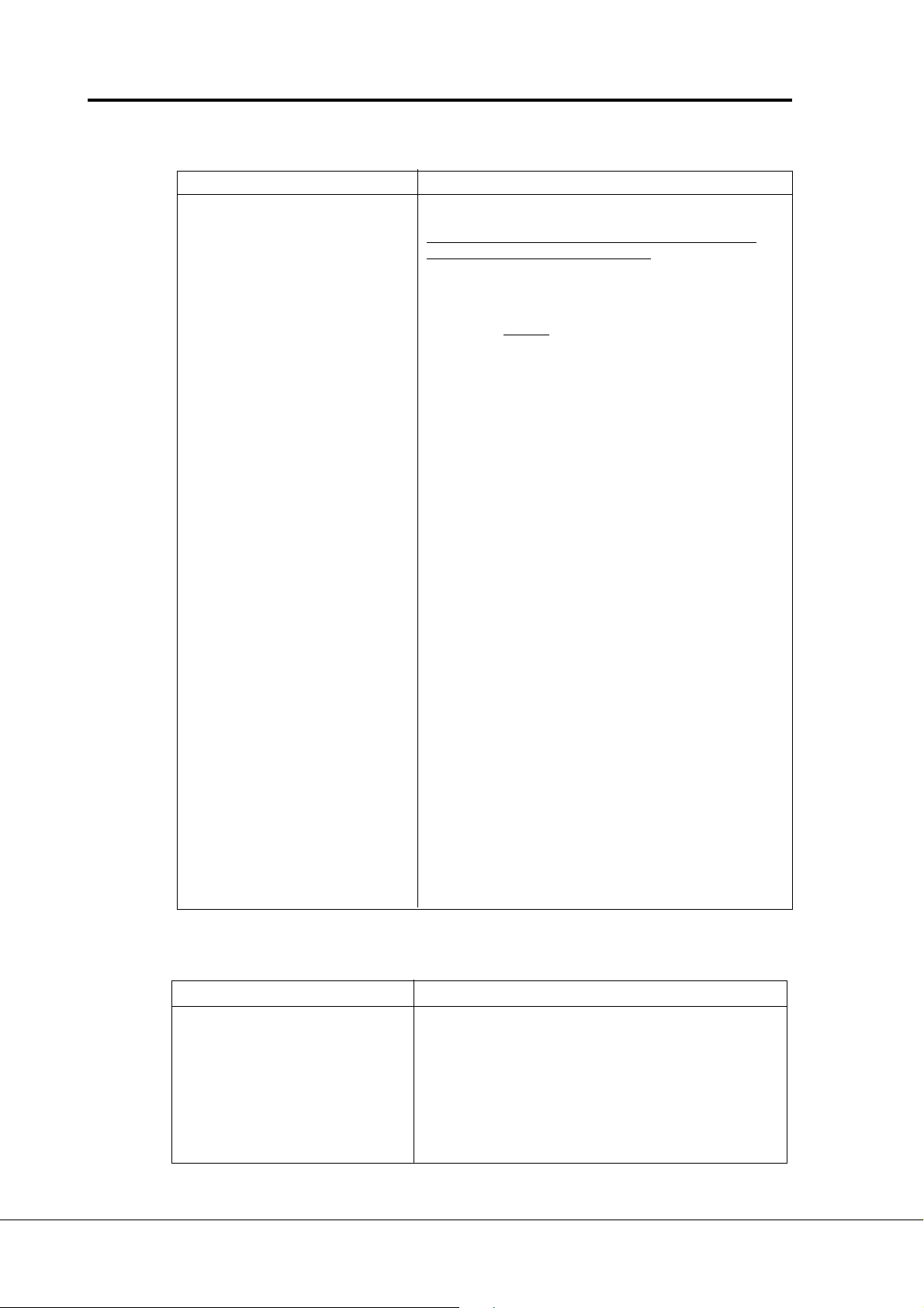
9: DC-braking contact closed = In the stop mode, the DC-braking operates
command until the contact is opened, see figure 6-1.
Dc-brake current is set with parameter 4. 8.
10: Motor pot. contact closed = Reference increases until the contact is
UP opened
11: Interlock inp., contact closed = Interlock of autochange drive 1 is active
autochange 1
Output
frequency
DIA3
RUN
STOP
DIA3 as DC-brake command input and stop-mode = Ramp
Figure 6-1 DIA3 as DC-brake
command input:
DIA3
a) Stop-mode = ramp,
b) Stop-mode = coasting
Vacon Plc Phone: +358-201 2121 Fax:+358-201 212 205
Service: +358-40-8371 150 E-mail: vacon@vacon.com
E-mail: application.team@vacon.com
DIA3 as DC-brake command input and stop-mode = Coasting
Param. 4. 10
t
UD009K32
t
UD009K32
Page 22

Page 22 Vacon
Pump and fan control with autochange
2. 2 DIA3 function
Selections are the same as in 2. 1 except :
10: Motor pot. contact closed = Reference decreases until the contact is
DOWN opened
2. 3 U
signal range
in
0 = Signal range 0—10 V
1 = Custom setting range from custom minimum (par. 2. 4) to custom
maximum (par. 2. 5)
2 = Signal range 2—10 V
2. 4 U
2. 5 With these parameters you can set U
custom setting minimum/maximum
in
for any input signal span of 0—10 V.
in
Minimum setting: Set the Uin signal to its minimum level, select parameter 2. 4,
press the Enter button
Maximum setting: Set the Uin signal to its maximum level, select parameter 2. 5,
press the Enter button
Note! The parameter values can only be set with this procedure (not with arrow up/arrow
down buttons)
2. 6 U
2. 7 U
signal inversion
in
Parameter 2. 6 = 1, inversion of analogue U
signal filter time
in
Filters out disturbances from the
incoming analogue U
signal.
in
Long filtering time makes regulation
%
100%
signal.
in
Unfiltered signal
response slower.
See figure 6-2.
Filtered signal
63%
Figure 6-2 U
signal filtering
in
Par. 2. 7
2. 8 Analogue input Iin signal range
0 = 0—20 mA
1 = 4—20 mA
2 = Custom signal span
2. 9 Analogue input Iin custom setting
2. 10 minimum/maximum
With these parameters you can scale the input current signal (Iin) signal range
between 0 and 20 mA. See par. 2. 4 and 2. 5.
Vacon Plc Phone: +358-201 2121 Fax:+358-201 212 205
Service: +358-40-8371 150 E-mail: vacon@vacon.com
t [s]
UD009K15
Page 23

Vacon Page 23
Pump control with autochange
2. 11 Analogue input I
Parameter 2. 11 = 1, inversion of I
2. 12 Analogue input I
Filters out disturbances from the
incoming analogue I
Long filtering time makes
regulation response slower.
See figure 6-3.
Figure 6-3 Analogue input Iin filter
time
2. 13 DIA5 function
inversion
in
filter time
in
signal.
in
input.
in
100%
63%
%
Unfiltered signal
Filtered signal
t [s]
Par. 2. 12
UD009K30
1: External fault, closing contact = Fault is shown and motor is stopped when
the input is active
2: External fault, opening contact = Fault is shown and motor is stopped when
the input is not active
3: Run enable contact open = Start of the motor disabled
contact closed = Start of the motor enabled
4: Acc. / Dec contact open = Acceleration/Deceleration time 1 selected
time select. contact closed = Acceleration/Deceleration time 2 selected
5: Reverse contact open = Forward
If two or more inputs are
contact closed = Reverse programmed to reverse then
if one of them is active the
direction is reverse
6: Jogging freq. contact closed = Jogging frequency selected for freq. refer.
7: Fault reset contact closed = Resets all faults
8: Acc./Dec. contact closed = Stops acceleration and deceleration until
operation the contact is opened
prohibited
9: DC-braking contact closed = In the stop mode, the DC-braking operates
command until the contact is opened, see figure 6-1.
DC-brake current is set with parameter 4. 8.
10: PI-contr. ref. contact closed = reference 2 (selected with par. 2.29) is
selection active
11: Interlock inp. contact closed = Interlock of autochange drive 3 is active
autochange 3
2. 14 Motor potentiometer ramp time
Defines how fast the electronic motor potentiometer value changes.
Vacon Plc Phone: +358-201 2121 Fax:+358-201 212 205
Service: +358-40-8371 150 E-mail: vacon@vacon.com
E-mail: application.team@vacon.com
Page 24

Page 24 Vacon
Pump and fan control with autochange
2. 15 PI-controller reference signal (place A)
0 Analogue voltage reference from terminals 2—3, e.g. a potentiometer
1 Analogue current reference from terminals 4—5, e.g. a transducer.
2 Panel reference is the reference set from the Reference Page (REF).
Reference r2 is the PI-controller reference, see chapter 6.
3 Reference value is changed with digital input signals DIA2 and DIA3.
- switch in DIA2 closed = frequency reference increases
- switch in DIA3 closed = frequency reference decreases
Speed of the reference change can be set with the parameter 2. 3.
4 Same as setting 3 but the reference value is set to the minimum frequency
(par. 1. 1) each time the frequency converter is stopped. When value of the
parameter 1. 5 is set to 3 or 4, value of the parameter 2.1 is automatically set
to 4 and value of the parameter 2. 2 is automatically set to 10.
5 Analogue voltage signal from the terminals 202—203 of the I/O-expander
6 Analogue signal from the terminals 204—205 of the I/O-expander
- current signal, Vacon CX 100 OPT
- voltage signal, Vacon CX 102 OPT
7 Fieldbus signal
2. 16 PI-controller actual value selection
0 Actual value 1
1 Sum of Actual value 1 and Actual value 2
2 Difference of Actual value 1 and Actual value 2
3 Multiplication of Actual value 1 and Actual value 2
4 Minor of signals Actual value 1 and Actual value 2 is active actual value
5 Major of signals Actual value 1 and Actual value 2 is active actual value
6 Mean value of Actual value 1 and Actual value 2 signals
7 Sum of square roots from Actual value 1 and Actual value 2
2. 17 Actual value 1
2. 18 Actual value 2
0 No signal
1 Analogue voltage reference from terminals 2—3
2 Analogue current reference from terminals 4—5
3 Analogue voltage signal from the terminals 202—203 of the I/O-expander
4 Analogue signal from the terminals 204—205 of the I/O-expander
- current signal, Vacon CX 100 OPT
- voltage signal, Vacon CX 102 OPT
5 Fieldbus signal
2. 19 Actual value 1 minimum scale
Sets the minimum scaling point for Actual value 1. See figure 6-4.
2. 20 Actual value 1 maximum scale
Sets the maximum scaling point for Actual value 1. See figure 6-4.
2. 21 Actual value 2 minimum scale
Sets the minimum scaling point for Actual value 2. See figure 6-4
2. 22 Actual value 2 maximum scale
Sets the maximum scaling point for Actual value 2. See figure 6-4
Vacon Plc Phone: +358-201 2121 Fax:+358-201 212 205
Service: +358-40-8371 150 E-mail: vacon@vacon.com
Page 25

Vacon Page 25
Pump control with autochange
Scaled
input signal [%]
100
Par. 2. 19 = 30%
Par. 2. 20 = 80%
0
0
0
4
1008030
10.0 V
8.03.0
20.0 mA
16.06.0
16.88.8 20.0 mA
2. 23 Error value inversion
This parameter allows you to invert the error value of the PI-controller (and thus the
operation of the PI-controller).
Figure 6-4 Examples about the scaling of actual value signal.
2. 24 PI-controller minimum limit
2. 25 PI-controller maximum limit
These parameters set the minimum and maximum values of the PI-controller output.
Parameter value limits: par 1.1 <par. 2. 24 <par. 2. 25.
Analogue
input [%]
(15.3 mA)
-30
100
76.5
17.7
(3.5 mA)
Scaled
input signal [%]
Par. 2. 19 = -30%
Par. 2. 20 = 140%
0
0
0
4
100 140
10.0 V
20.0 mA
20.0 mA
Analogue
input [%]
UD012K34
2. 26 Direct frequency reference, Place B
0 Analogue voltage reference from terminals 2—3, e.g. a potentiometer
1 Analogue current reference from terminals 4—5, e.g. a transducer.
2 Panel reference is the reference set from the Reference Page (REF),
Reference r1 is the Place B reference, see chapter 6.
3 Reference value is changed with digital input signals DIA2 and DIA3.
- switch in DIA2 closed = frequency reference increases
- switch in DIA3 closed = frequency reference decreases
Speed of the reference change can be set with the parameter 2. 3.
4 Same as setting 3 but the reference value is set to the minimum frequency
(par. 1. 1) each time the frequency converter is stopped. When value of the
parameter 1. 5 is set to 3 or 4, value of the parameter 2. 1 is automatically set
to 4 and value of the parameter 2. 2 is automatically set to 10.
2. 27 Place B reference scaling, minimum value/maximum value
2. 28 Setting limits: 0 < par. 2. 27 < par. 2. 28 < par. 1. 2.
If par. 2. 28 = 0 scaling is set off. See figures 6-5 and 6-6.
(In the figures voltage input Uin with signal range 0—10 V selected for source B reference)
See Figure 6-5 Reference scaling and Figure 6-6 Reference scaling, par. 2.15 = 0.
(next page).
Vacon Plc Phone: +358-201 2121 Fax:+358-201 212 205
Service: +358-40-8371 150 E-mail: vacon@vacon.com
E-mail: application.team@vacon.com
Page 26

Page 26 Vacon
Pump and fan control with autochange
Par. 2. 28
Par. 2. 27
Output
frequency
Max freq. par 1. 2
Min freq. par 1. 1
100
Analogue
input [V]
Output
frequency
Max freq. par 1. 2
Min freq. par 1. 1
2. 29 PI-controller reference signal 2 (place A)
0 Analogue voltage reference from terminals 2—3, e.g. a potentiometer
1 Analogue current reference from terminals 4—5, e.g. a transducer.
2 Panel reference is the reference set from the Reference Page (REF).
Reference r2 is the PI-controller reference, see chapter 6.
3 Reference value is changed with digital input signals DIA2 and DIA3.
- switch in DIA2 closed = frequency reference increases
- switch in DIA3 closed = frequency reference decreases
Speed of the reference change can be set with the parameter 2. 3.
4 Same as setting 3 but the reference value is set to the minimum frequency
(par. 1. 1) each time the frequency converter is stopped. When value of the
parameter 1. 5 is set to 3 or 4, value of the parameter 2.1 is automatically set
to 4 and value of the parameter 2. 2 is automatically set to 10.
5 Analogue voltage signal from the terminals 202—203 of the I/O-expander
6 Analogue signal from the terminals 204—205 of the I/O-expander
- current signal, Vacon CX 100 OPT
- voltage signal, Vacon CX 102 OPT
7 Panel reference r3, can be set on the Reference Page (REF) of the panel.
100
UD012K35
Analogue
input [V]
2. 30 Ain1
signal inversion (I/O-expander)
Parameter 2. 30 = 0, no inversion
2. 31 Ain1
signal filter time
Filters out disturbances from the incoming analogue Ain1 signal. Long filtering time
makes regulation response slower.
2. 32 Ain2 input (I/O-expander) signal range
0 = 0—20 mA
1 = 4—20 mA
2 = 0-10 V (must be used with 102 OPT)
2. 33 Ain2
signal inversion (I/O-expander)
Parameter 2. 33 = 0, no inversion
2. 34 Ain2
signal filter time
Filters out disturbances from the incoming analogue Ain2 signal. Long filtering time
makes regulation response slower.
Vacon Plc Phone: +358-201 2121 Fax:+358-201 212 205
Service: +358-40-8371 150 E-mail: vacon@vacon.com
Page 27

Vacon Page 27
Pump control with autochange
3. 1 Analogue output function
See table on page 13.
3. 2 Analogue output filter time
Filters the analogue output signal.
See figure 6-7.
Figure 6-7 Analogue output filtering.
3.3 Analogue output invert
Inverts analogue output signal:
max. output signal = minimum set
value
min. output signal = maximum set
value
%
100%
63%
Analogue
output
current
20 mA
12 mA
10 mA
Unfiltered signal
Par. 3. 2
Filtered signal
t [s]
UD009K16
Param. 3. 5
= 50%
Figure 6-8 Analogue output invert.
3. 4 Analogue output minimum
Defines the signal minimum to
be either 0 mA or 4 mA (living
zero). See figure 6-9.
3. 5 Analogue output scale
Scaling factor for analogue output.
See figure 6-9.
Signal Max. value of the signal
Output freq. Max. frequency (p. 1. 2)
Motor speed Max. speed (n
Output 2 x I
current
Motor torque 2 x T
Motor power 2 x P
Motor voltage 100% x U
nCX
nCX
nCX
DC-link volt. 1000 V
PI-ref. value 100% x ref. value max.
PI-act. value1 100% x act. value max.
PI-act. value2 100% x act. value max.
PI-error value 100%x error value max.
PI-output 100% x output max.
nxfmax/fn
nmotor
Param. 3. 5
4 mA
Param. 3. 5
0 mA
0
Analogue
output
current
)
20 mA
12 mA
10 mA
Par. 3. 4 = 1
4 mA
Par. 3. 4 = 0
0 mA
0
= 200%
0.5
Param. 3. 5
= 200%
0.5
= 100%
Selected (para. 3. 1)
signal max. value
1.0
UD012K17
Param. 3. 5
= 100%
Param. 3. 5
= 50%
Max. value of signal
selected by param. 3. 1
1.0
UD012K18
Figure 6-9 Analogue output
Vacon Plc Phone: +358-201 2121 Fax:+358-201 212 205
Service: +358-40-8371 150 E-mail: vacon@vacon.com
E-mail: application.team@vacon.com
Page 28
Page 28 Vacon
Pump and fan control with autochange
scale.
3. 6 Digital output function
Setting value Signal content
0 = Not used Out of operation
Digital output DO1 sinks current and programmable
relay (RO1, RO2) is activated when:
1 = Ready The frequency converter is ready to operate
2 = Run The frequency converter operates (motor is running)
3 = Fault A fault trip has occurred
4 = Fault inverted A fault trip
5 = Vacon overheat warning The heat-sink temperature exceeds +70°C
6 = External fault or warning Fault or warning depending on parameter 7. 2
7 = Reference fault or warning Fault or warning depending on parameter 7. 1
- if analogue reference is 4—20 mA and signal is <4mA
8 = Warning Always if a warning exists
9 = Reversed The reverse command has been selected
10= Multi-step or jogging speed Multi-step or jog. speed has been selected with digital
input
11 = At speed The output frequency has reached the set reference
12 = Motor regulator activated Overvoltage or overcurrent regulator was activated
13 = Output frequency supervision 1 The output frequency goes beyond the set supervision
Low limit/ High limit (par. 3. 9 and par. 3. 10)
14= Output frequency supervision 2 The output frequency goes beyond the set supervision
Low limit/ High limit (par. 3. 11 and par. 3. 12)
15= Torque limit supervision The motor torque goes beyond the set supervision
Low limit/ High limit (par. 3. 13 and par. 3. 14)
16= Active reference Active reference goes beyond the set supervision
limit supervision Low limit/ High limit (par. 3. 15 and par. 3. 16)
17 = External brake control External brake ON/OFF control with programmable de
lay (par 3. 17 and 3. 18)
18 = Control from I/O terminals External control mode selected with pr. push-button #2
19 = Frequency converter Temperature on frequency converter goes beyond
temperature limit supervision set supervision limits (par. 3. 19 and 3. 20)
20 = Unrequested rotation direction Rotation direction of the motor shaft is different from the
requested one
21 = External brake control inverted External brake ON/OFF control (par. 3.17 and 3.18),
output active when brake control is ON
22= Analog input limit supervision The level of selected analog input goes beyond the
set supervision low / high limit (par. 3. 29 and par. 3. 30)
23—26 = Not in use
27 = Autochange 3 control Control signal for drive 3 in autochange system
28 = Auxiliary drive 1 start Starts and stops auxiliary drive 1
29 = Auxiliary drive 2 start Starts and stops auxiliary drive 2
30 = Auxiliary drive 3 start Starts and stops auxiliary drive 3
has not occurred
Table 6-3a Output signals via DO1
3. 7 Relay output 1 content
Setting value Signal content
0-22 = Same as parameter 3.6
23—25 = Not in use
26 = Autochange 1 control Control signal for drive 1 in autochange system
27 = Autochange 4 control Control signal for drive 1 in autochange system with
I/O-expander option
28 = Auxiliary drive 1 start Starts and stops auxiliary drive 1
29 = Auxiliary drive 2 start Starts and stops auxiliary drive 2
30 = Auxiliary drive 3 start Starts and stops auxiliary drive 3
Table 6-3b Output signals via RO1
Vacon Plc Phone: +358-201 2121 Fax:+358-201 212 205
Service: +358-40-8371 150 E-mail: vacon@vacon.com
Page 29
Vacon Page 29
Pump control with autochange
3. 8 Relay output 2 content
Setting value Signal explanation
0-22 = Same as parameter 3.6
23—25 = Not in use
26 = Autochange 2 control Control signal for drive 2 in autochange system
27 = Autochange 5 control Control signal for drive 5 in autochange system with
I/O-expander option
28 = Auxiliary drive 1 start Starts and stops auxiliary drive 1
29 = Auxiliary drive 2 start Starts and stops auxiliary drive 2
30 = Auxiliary drive 3 start Starts and stops auxiliary drive 3
Table 6-3c Output signals via RO2
3. 9 Output frequency limit 1,
supervision function
3. 11 Output frequency limit 2,
f[Hz]
supervision function
0 = No supervision
Par 3. 10
1 = Low limit supervision
2 = High limit supervision
Par. 3.9 = 2
If the output frequency goes under/
over the set limit (3. 10, 3. 12) this
function generates a warning
message via the digital output DO1
Example:
21 RO1
22 RO1
23 RO1
21 RO1
22 RO1
23 RO1
UD009K19
21 RO1
22 RO1
23 RO1
or via the relay output RO1 or RO2
depending on the settings of the
Figure 6-10 Output frequency supervision.
parameters 3. 6—3. 8.
t
3. 10 Output frequency limit 1, supervision value
3. 12 Output frequency limit 2, supervision value
The frequency value to be supervised by the parameter 3. 9 (3. 11).
See figure 6-10.
3. 13 Torque limit, supervision
function
0 = No supervision
1 = Low limit supervision
2 = High limit supervision
If the calculated torque value goes under/over the set limit (3. 14) this function
generates a warning message via the digital output DO1 or via a relay output RO1
or RO2 depending on the settings of the parameters 3. 6—3. 8.
3. 14 Torque limit, supervision value
The calculated torque value to be supervised by the parameter 3. 13.
Vacon Plc Phone: +358-201 2121 Fax:+358-201 212 205
Service: +358-40-8371 150 E-mail: vacon@vacon.com
E-mail: application.team@vacon.com
Page 30

Page 30 Vacon
Pump and fan control with autochange
3. 15 Active reference limit, supervision function
0 = No supervision
1 = Low limit supervision
2 = High limit supervision
If the reference value goes under/over the set limit (3. 16) this function generates a
warning message via the digital output DO1 or via a relay output RO1 or
RO2 depending on the settings of the parameters 3. 6—3. 8. The supervised
reference is the current active reference. It can be source A or B reference depending
on DIB6 input or panel reference if the panel is the active control source.
3. 16 Active reference limit, supervision value
The frequency value to be supervised by the parameter 3. 15.
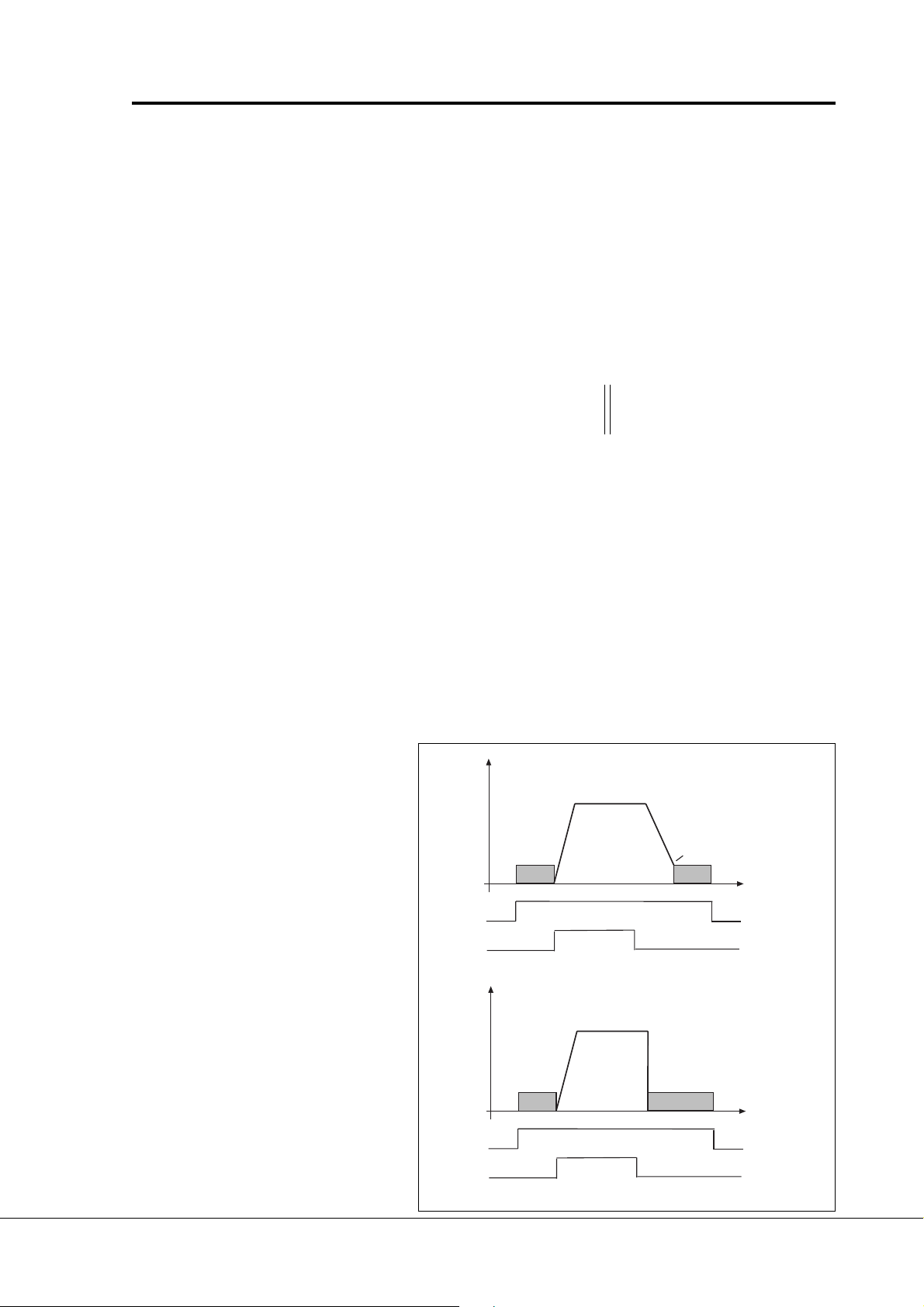
3. 17 External brake-off delay
3. 18 External brake-on delay
With these parameters the timing of external brake can be linked to the Start
and Stop control signals, see figure 6-11.
The brake control signal can be programmed via the digital output DO1 or via one
of relay outputs RO1 and RO2, see parameters 3. 6—3. 8.
The temperature value to be supervised by the parameter 3. 20.
a)
t
= Par. 3. 17 tON = Par. 3. 18
OFF
External
BRAKE: OFF
ON
DIA1: RUN FWD
STOP
DIA2: RUN REV
STOP
b)
External
BRAKE: OFF
ON
DIA1: START
PULSE
DIA2: STOP
PULSE
t
= Par. 3. 17 tON = Par. 3. 18
OFF
Digital or
relay output
UD012K45
Digital or
relay output
t
t
Figure 6-11 External brake control:
a) Start/Stop logic selection par. 2. 1 = 0, 1 or 2
b)Start/Stop logic selection par. 2. 1 = 3.
Vacon Plc Phone: +358-201 2121 Fax:+358-201 212 205
Service: +358-40-8371 150 E-mail: vacon@vacon.com
Page 31

Vacon Page 31
Pump control with autochange
3. 19 Frequency converter temperature limit supervision function
0 = No supervision
1 = Low limit supervision
2 = High limit supervision
If the temperature of the frequency converter goes under/over the set limit (3. 20)
this function generates a warning message via the digital output DO1 or via a relay
output RO1 or RO2 depending on the settings of the parameters 3. 6—3. 8.
3. 20 Frequency converter temperature limit value
The temperature value to be supervised by the parameter 3. 19.
3. 26 Analogue output offset
3. 27 I/O-expander analogue output offset
With these parameters can be set the offsets of the basic control board and I/Oexpander analogue outputs. See figure 6-12.
Analogue
output
current
20 mA
Param. 3. 5
= 100%
Param. 3. 26
= -30%(-6mA)
Param. 3. 26
= 25% (+5 mA)
Maximum value of
0 mA
0
0.5
selected signal
1.0
Figure 6-12 Analogue output offset
3. 28 Analogue input supervision, input signal selection
0 Analogue voltage signal from terminals 2—3
1 Analogue current signal from terminals 4—5
2 Analogue voltage signal from terminals 202—203 of the I/O-expander
3 Analogue signal from the terminals 204—205 of the I/O-expander
- current signal, Vacon CX 100 OPT
- voltage signal, Vacon CX 102 OPT
3. 29 Analoque input supervision function
0 = No supervision
1 = Low limit supervision
2 = High limit supervision
ao-offse.fh3
If the value of the selected analogue input (par. 3.28) goes under/over the set limit
(3. 30) this function generates a warning message via the digital output DO1 or via
a relay output RO1 or RO2 depending on the settings of the parameters 3. 6—3. 8.
3. 30 Analoque input supervision limit value
The value of the analogue input to be supervised by the parameter 3. 29.
Vacon Plc Phone: +358-201 2121 Fax:+358-201 212 205
Service: +358-40-8371 150 E-mail: vacon@vacon.com
E-mail: application.team@vacon.com
Page 32

Page 32 Vacon
Pump and fan control with autochange
4. 1 Acc/Dec ramp 1 shape
4. 2 Acc/Dec ramp 2 shape
The start and end of the acceleration and deceleration ramps can be smoothed with
these parameters. Setting value 0 gives a linear ramp shape which causes
acceleration and deceleration to react immediately to the changes in the reference
signal with the time constant set by the parameter 1. 3 and 1. 4 (4. 3 and 4. 4).
Setting value 0.1—10 seconds for 4.1 (4.2) causes linear acceleration/deceleration
to adopt an S-shape. Parameters 1. 3 and 1. 4 (4. 3 and 4. 4) determine the time
constant of acceleration/deceleration in the middle of the curve.
See figure 6-13.
4. 3 Acceleration time 2
4. 4 Deceleration time 2
These values correspond to the time required for the output frequency to accelerate
from the set minimum frequency (par. 1. 1) to the set maximum frequency
(par. 1. 2). These times give the possibility to set two different acceleration/
deceleration time sets for one application. The active set can be selected with the
programmable signal DIA3 of this application, see parameter 2. 2. Acceleration/
deceleration times can be reduced with an external free analogue input signal, see
parameters 2. 18 and 2. 19.
4. 5 Brake chopper
0 = No brake chopper
1 = Brake chopper and brake resistor installed
2 = External brake chopper
When the frequency converter is decelerating the motor, the inertia from the motor
and the load is fed into the external brake resistor. This enables the frequency
converter to decelerate the load with the torque equal to that of acceleration, if the
brake resistor is selected correctly. See separate Brake resistor installation manual.
[Hz]
1. 3, 1. 4
(4. 3, 4. 4)
4. 1 (4. 2)
4. 1 (4. 2)
Figure 6-13 S-shaped acceleration / deceleration.
[t]
UD009K20
Vacon Plc Phone: +358-201 2121 Fax:+358-201 212 205
Service: +358-40-8371 150 E-mail: vacon@vacon.com
Page 33

Vacon Page 33
Pump control with autochange
4. 6 Start function
Ramp:
0 The frequency converter starts from 0 Hz and accelerates to the set reference
frequency within the set acceleration time. (Load inertia or starting friction may
cause prolonged acceleration times).
Flying start:
1 The frequency converter is able to start into running motor by applying a small
torque to motor and searching for frequency corresponding to the speed the
motor is running at. Searching starts from the maximum frequency towards
the actual frequency until the correct value is detected. Thereafter the output
frequency will be accelerated/decelerated to the set reference value according
to the set acceleration/deceleration parameters.
Use this mode if the motor may be coasting when the start command is given.
With the flying start it is possible to ride through short mains voltage
interruptions.
4. 7 Stop function
Coasting:
0 The motor coasts to a halt without any control from the frequency converter,
after the Stop command.
Ramp:
1 After the Stop command, the speed of the motor is decelerated according to
the set deceleration parameters. If the regenerated energy is high it may be
necessary to use an external braking resistor for faster deceleration.
4. 8 DC braking current
Defines the current injected into the motor during the DC braking.
Vacon Plc Phone: +358-201 2121 Fax:+358-201 212 205
Service: +358-40-8371 150 E-mail: vacon@vacon.com
E-mail: application.team@vacon.com
Page 34
Page 34 Vacon
Pump and fan control with autochange
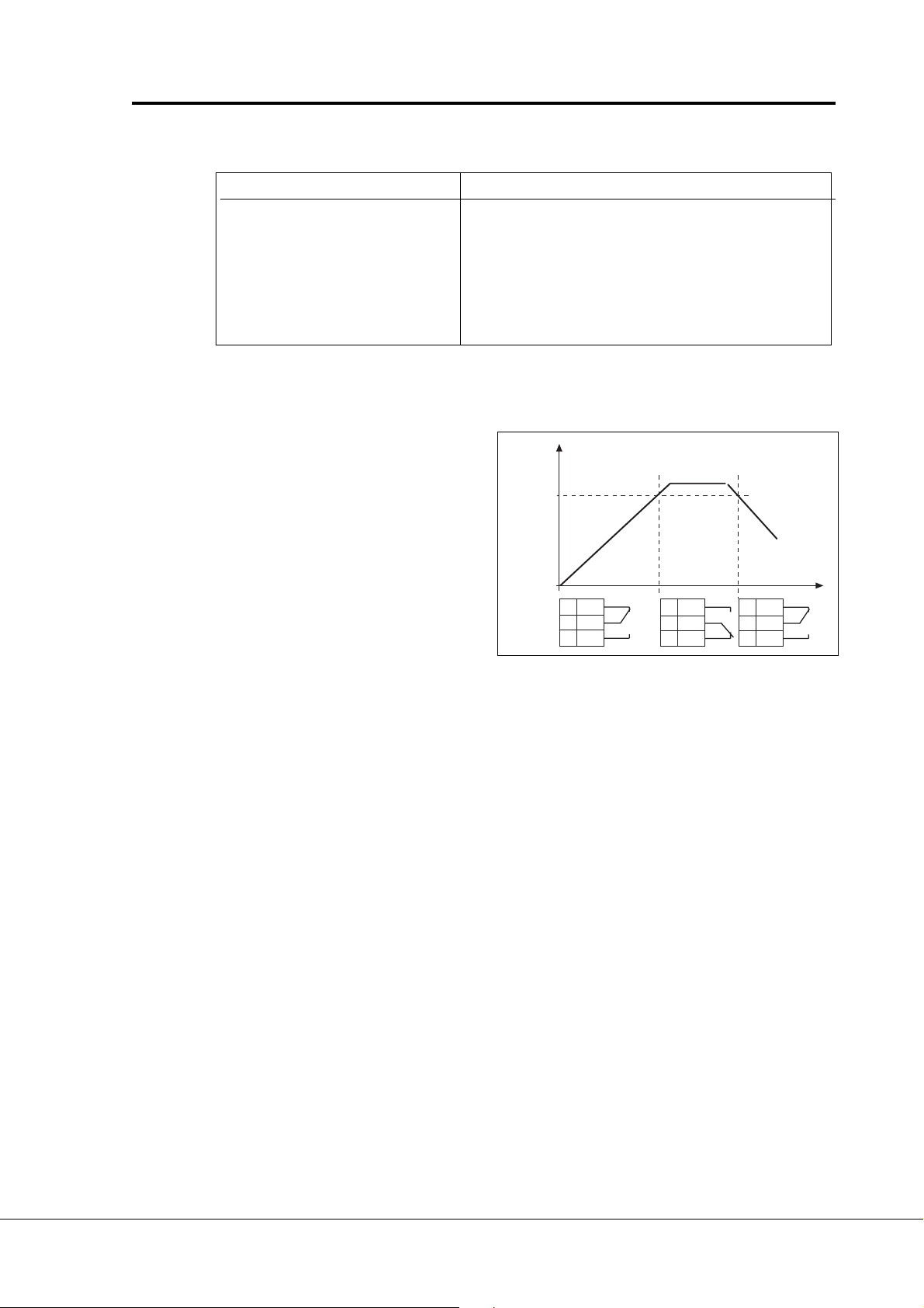
4. 9 DC braking time at stop
Defines if braking is ON or OFF and braking time of the DC-brake when the motor is
stopping. The function of the DC-brake depends on the stop function, parameter 4.
7. See figure 6-14.
0 DC-brake is not used
>0 DC-brake is in use and its function depends on the Stop function,
(param. 4. 7), and the time depends on the value of parameter 4. 9:
Stop-function = 0 (coasting):
After the stop command, the motor coasts to a stop without any control from
the frequency converter.
With DC-injection, the motor can be electrically stopped in the shortest possible
time, without using an optional external braking resistor.
The braking time is scaled according to the frequency when the DC-
braking starts. If the frequency is >nominal frequency of the motor (par. 1.11),
the setting value of parameter 4.9 determines the braking time. When the
frequency is <10% of the nominal, the braking time is 10% of the set
value of parameter 4.9.
f
f
n
RUN
STOP
out
Output frequency
Motor speed
DC-braking ON
t
t = 1 x par. 4. 9
f
n
0,1x f
RUN
STOP
f
Figure 6-14 DC-braking time when par. 4. 7 = 0.
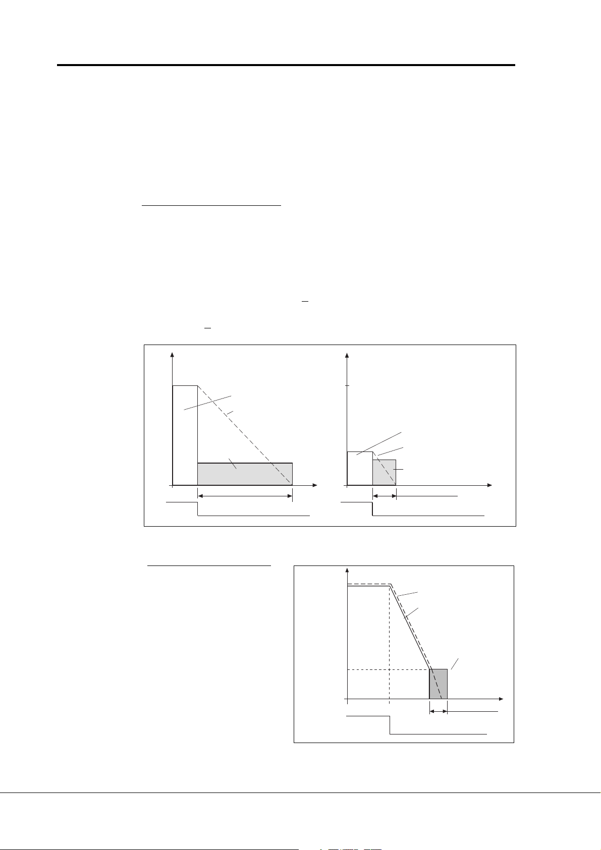
Stop-function = 1 (ramp):
After the Stop command,
the speed of the motor is
reduced according to the
set deceleration parameters, as fast as
possible, to a speed
defined with the parameter
4. 10, where the DC-
Param. 4. 10
braking starts. The braking
time is defined with parameter 4. 9. If high inertia
exists, it is recommended
RUN
STOP
to use an external braking
resistor for faster
Figure 6-15 DC-braking time when par. 4. 7 = 1.
deceleration. See figure
6-15.
out
f
out
Output frequency
Motor speed
n
DC-braking ON
t = 0.1 x par. 4. 9
Motor speed
Output frequency
DC-braking
t = param. 4. 9
t
UD009K21
t
UD009K23
Vacon Plc Phone: +358-201 2121 Fax:+358-201 212 205
Service: +358-40-8371 150 E-mail: vacon@vacon.com
Page 35

Vacon Page 35
Pump control with autochange
4. 10 Execute frequency of DC-brake during ramp Stop
See figure 6-15.
4. 11 DC-brake time at start
0 DC-brake is not used
>0 DC-brake is activated when
the start command is given
and this parameter defines
the time before the brake is
released. After the brake is
released, the output frequency increases according to the set start function
parameter
4.6 and accelera-
tion parameters (1. 3, 4. 1 or
4.2, 4.3), see figure 6-16.
Figure 6-16 DC-braking time at start
4. 12 Jogging speed reference
Parameter value defines the jogging speed selected with the digital input.
5. 1 Prohibit frequency area,
5. 2 Low limit/High limit
5. 3
5. 4
5. 5
5. 6
Output
frequency
RUN
STOP
f
out
[Hz]
t
Par 4. 11
UD009K22
In some systems it may be
necessary to avoid certain
frequencies because of
mechanical resonance problems.
With these parameters it is
possible to set limits for three "skip
frequency" regions.
Figure 6-17 Example of prohibit
frequency area setting.
6. 1 Motor control mode
0 = Frequency control: The I/O terminal and panel references are frequency
1 = Speed control: The I/O terminal and panel references are speed
frequency
reference
5. 1 5. 2
5. 3 5. 4
5. 5 5. 6
[Hz]
UD009K33
references and the frequency converter controls the
output frequency (output freq. resolution 0,01 Hz)
references and the frequency converter controls the
motor speed (regulation accuracity ± 0,5%).
Vacon Plc Phone: +358-201 2121 Fax:+358-201 212 205
Service: +358-40-8371 150 E-mail: vacon@vacon.com
E-mail: application.team@vacon.com
Page 36

Page 36 Vacon
Pump and fan control with autochange
6. 2 Switching frequency
Motor noise can be minimized by using high switching frequency. Increasing the
frequency reduces the capacity of the frequency converter. Before changing the
frequency from the factory default 10 kHz (3.6 kHz from 30 kW upwards), check the
allowed capacity from the curves in the figure 5.2-3 of the User's Manual.
6. 3 Field weakening point
6. 4 Voltage at the field weakening point
Field weakening point is the output frequency where the output voltage reaches the
set maximum value (par. 6. 4). Above that frequency the output voltage remains at
the set maximum value.
Below that frequency output voltage depends on the setting of the U/f curve
parameters 1. 8, 1. 9, 6. 5, 6. 6 and 6. 7. See figure 6-18.
When the parameters 1. 10 and 1. 11, nominal voltage and nominal frequency of
the motor, are set, also parameters 6. 3 and 6. 4 are set automatically to the
corresponding values. If different values for the field weakening point and
the maximum output voltage are required, change these parameters
after setting
the parameters 1. 10 and 1. 11.
6. 5 U/f curve, middle point frequency
If the programmable U/f curve has been selected with the parameter 1. 8 this
parameter defines the middle point frequency of the curve. See figure 6-18.
6. 6 U/f curve, middle point voltage
If the programmable U/f curve has been selected with the parameter 1. 8 this
parameter defines the middle point voltage (% from motor nom. voltage) of the
curve. See figure 6-18.
6. 7 Output voltage at zero frequency
If the programmable U/f curve has been selected with the parameter 1. 8 this
parameter defines the zero frequency voltage of the curve. See figure 6-18.
U[V]
Un
Par 6. 4
Par. 6. 6
(Olet. 10%)
Par. 6. 7
(Olet. 1.3%)
Par. 6. 5
(Olet. 5 Hz)
Par. 6. 3
f[Hz]
UD009K08
Figure 6-18 Programmable U/f curve.
Vacon Plc Phone: +358-201 2121 Fax:+358-201 212 205
Service: +358-40-8371 150 E-mail: vacon@vacon.com
Page 37

Vacon Page 37
Pump control with autochange
6. 8 Overvoltage controller
6. 9 Undervoltage controller
These parameters allow the over/undervoltage controllers to be switched out of
operation. This may be useful, for example, if the mains supply voltage varies more
than -15%—+10% and the application will not tolerate this over-/undervoltage, the
regulator controls output frequency according to the supply fluctuations.
Over/undervoltage trips may occur when controllers are switched out of operation.
7. 1 Response to the reference fault
0 = No response
1 = Warning
2 = Fault, stop mode after fault according to parameter 4.7
3 = Fault, stop mode after fault always by coasting
A warning or a fault action and message is generated if 4—20 mA reference signal
is used and the signal falls below 4 mA. The information can also be programmed
via digital output DO1 and via relay outputs RO1 and RO2.
7. 2 Response to external fault
0 = No response
1 = Warning
2 = Fault, stop mode after fault according to parameter 4.7
3 = Fault, stop mode after fault always by coasting
A warning or a fault action and message is generated from the external fault signal
in the digital input DIA3. The information can also be programmed into digital output
DO1 and into relay outputs RO1 and RO2.
7. 3 Phase supervision of the motor
0 = No action
2 = Fault
Phase supervision of the motor ensures that the motor phases have approximately
equal current.
7. 4 Earth fault protection
0 = No action
2 = Fault message
Earth fault protection ensures that the sum of the motor phase currents is zero.
The overcurrent protection is always working and protects the frequency converter
from earth faults with high currents.
Parameters 7. 5—7. 9 Motor thermal protection
General
Motor thermal protection is to protect the motor from overheating. Vacon CX/CXL/CXS drive is
capable of supplying higher than nominal current to the motor. If the load requires this high current
there is a risk that motor will be thermally overloaded. This is true especially at low frequencies.
With low frequencies the cooling effect of the motor is reduced and the capacity of the motor is
reduced. If the motor is equipped with an external fan the load reduction on low speeds is small.
Vacon Plc Phone: +358-201 2121 Fax:+358-201 212 205
Service: +358-40-8371 150 E-mail: vacon@vacon.com
E-mail: application.team@vacon.com
Page 38

Page 38 Vacon
Pump and fan control with autochange
Motor thermal protection is based on a calculated
model and it uses the output current of the drive to
determine the load on the motor. When the power
is turned on to the drive, the calculated model uses
the heatsink temperature to determine the initial
thermal stage for the motor. The calculated model
assumes that the ambient temperature of the motor
is 40°C.
Motor thermal protection can be adjusted by setting
the parameters. The thermal current IT specifies
the load current above which the motor is overloaded.
This current limit is a function of the output
frequency. The curve for IT is set with parameters 7.
6, 7. 7 and 7. 9 (refer to the figure 5-18). The
parameters have their default values set from the
motor name plate data.
!
CAUTION!
The calculated model does not protect the motor if the airflow to the
motor is reduced by blocked air intake grill.
7. 5 Motor thermal protection
With the output current at IT the thermal stage will
reach the nominal value (100%). The thermal stage
changes by the square of the current. With output
current at 75% of IT the thermal stage will reach
56% level and with output current at 120% from I
the thermal stage would reach 144% level. The
function will trip the device (refer par. 7. 5) if the
thermal stage will reach a value of 105%. The speed
of change in thermal stage is determined with the
time constant parameter 7. 8. The bigger the motor
the longer it takes to reach the final temperature.
The thermal stage of the motor can be monitored
through the display. Refer to the table for monitoring
items. (User's Manual, table 7.3-1).
T
Operation:
0 = Not in use
1 = Warning
2 = Trip function
Tripping and warning will display the same message code. If the tripping is selected
the drive will stop and activate the fault stage.
Deactivating the protection, setting parameter to 0, will reset the thermal stage of
the motor to 0%.
7. 6 Motor thermal protection, break point current
The current can be set between 50.0—150.0% x I
This parameter sets the value for thermal current at frequencies above the
break point on the thermal current curve. Refer to the figure 6.5-18.
The value is set in percentage which refers to the name plate data of the
motor, parameter 1. 13, nominal current of the motor, not the drive's nominal output
current.
The motor's nominal current is the current which the motor can withstand in direct
on-line use without being overheated.
If parameter 1. 13 is adjusted, this parameter is automatically restored to the default
value.
nMotor
.
Setting this parameter (or parameter 1. 13) does not affect the maximum output
current of the drive. Parameter 1. 7 alone determines the maximum output
current of the drive.
Vacon Plc Phone: +358-201 2121 Fax:+358-201 212 205
Service: +358-40-8371 150 E-mail: vacon@vacon.com
Page 39
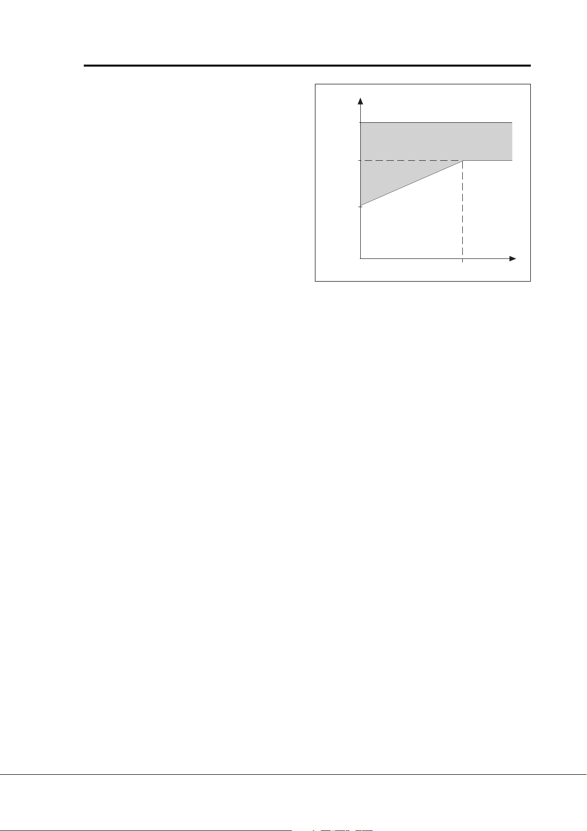
Vacon Page 39
Pump control with autochange
I
Current
limit
par. 1. 7
Par. 7. 6
Par. 7. 7
Figure 6-19 Motor thermal current
IT curve.
7. 7 Motor thermal protection, zero frequency current
The current can be set between 10.0—150.0% x I
nMotor
value for thermal current at zero frequency. Refer to the figure 5-18.
The default value is set assuming that there is no external fan cooling the motor. If
an external fan is used this parameter can be set to 90% (or even higher).
The value is set as a percentage of the motor
name plate data, parameter 1. 13, motor's
nominal current, not the drive's nominal
output current. Motor's nominal current is the
current which the motor can stand in direct
on-line use without being overheated.
If you change the parameter 1. 13 this
parameter is automatically restored to the
default value.
Setting this parameter (or parameter 1. 13)
does not affect to the maximum output
current of the drive. Parameter 1. 7 alone
determines the maximum output current of
the drive.
Overload area
Par. 7. 9
. This parameter sets the
f
UMCH7_91
I
T
7. 8 Motor thermal protection, time constant
The time can be set between 0.5—300 minutes. This
is the thermal time constant of the motor. The bigger the motor the bigger the time
constant. The time constant is the time when the calculated thermal stage has
reached 63% of its final value.
The motor thermal time is specific for the
motor design and it varies between different
motor manufacturers.
The default value for the time constant is
calculated on the basis of the motor name
plate data given with parameters 1. 12 and
1. 13. If either of these parameters is set,
then this parameter is set to default value.
If the motor's t6 -time is known (given by the
motor manufacturer) the time constant
Vacon Plc Phone: +358-201 2121 Fax:+358-201 212 205
Service: +358-40-8371 150 E-mail: vacon@vacon.com
E-mail: application.team@vacon.com
parameter could be set based on t6 -time.
As a rule of thumb, the motor thermal time
constant in minutes equals to 2xt6 (t6 in
seconds is the time a motor can safely
operate at six times the rated current). If the
drive is in stop stage the time constant is
internally increased to three times the set
parameter value. The cooling in the stop stage
is based on convection and the time constant
is increased.
Page 40

Page 40 Vacon
Pump and fan control with autochange
7. 9 Motor thermal protection, break point frequency
The frequency can be set between 10—500 Hz. This
is the break point of thermal current curve. With frequencies above this point the
thermal capacity of the motor is assumed to be constant. Refer to the figure 6-19.
The default value is based on the motor's name plate data, parameter 1. 11. It is 35
Hz for a 50 Hz motor and 42 Hz for a 60 Hz motor. More generally, it is 70% of the
frequency at field weakening point (parameter 6. 3). Changing either parameter 1.
11 or 6. 3 will restore this parameter to its default value.
Motor temperature
Figure 6-20 Calculating motor temperature
Trip area
105%
Motor
current
I/I
T
Time constant T
Motor temperature
*)
adjusted with parameter 7. 8
*)
Θ = (I/IT)2 x (1-e
Changed with motor size and
Trip/warning
par. 7. 5
-t/T
)
Time
UMCH7_92
Parameters 7. 10— 7. 13, Stall protection
General
Motor stall protection protects the motor from short time overload situations caused by e.g. a
stalled shaft. The reaction time of stall protection can be set shorter than that of motor thermal
protection. The stall state is defined with two parameters, 7.11. Stall Current and 7.13. Stall
Frequency. If the current is higher than the set limit and output frequency is lower than the set
limit the stall state is true. There is actually no real indication of the shaft rotation. Stall protection
is a type of overcurrent protection.
7. 10 Stall protection
Operation:
0 = Not in use
1 = Warning
2 = Trip function
Tripping and warning will display the same message code. If the tripping is set on,
the drive will stop and activate the fault stage.
Setting the parameter to 0 will deactivate the protection and will reset the stall time
counter to zero.
Vacon Plc Phone: +358-201 2121 Fax:+358-201 212 205
Service: +358-40-8371 150 E-mail: vacon@vacon.com
Page 41

Vacon Page 41
Pump control with autochange
7. 11 Stall current limit
The current can be set between
0.0—200% x I
nMotor
In the stall stage the current has to
be above this limit. Refer to the
figure6-21. The value is set as a
percentage of the motor's name
plate data, parameter 1. 13,
motor's nominal current. If
parameter 1. 13 is adjusted, this
parameter is automatically
restored to the default value.
Figure 6-21 Setting the stall
characteristics.
7. 12 Stall time
The time can be set between 2.0—120 s.
This is the maximum allowed time for a stall stage. There is an internal up/down
counter to count the stall time. Refer to the figure 6-22.
If the stall time counter value goes above this limit the protection will cause a trip
(refer to the parameter 7. 10).
I
.
Stall area
Par. 7. 11
f
Par. 7. 13
UMCH7_11
7. 13 Maximum stall frequency
Stall time counter
The frequency can be set between
1—f
In the stall state, the ouput
frequency has to be smaller than
this limit. Refer to the figure 6-21.
Figure 6-22 Counting the stall time.
(par. 1. 2).
max
Par. 7. 12
Stall
No stall
Trip area
Trip/warning
par. 7. 10
UMCH7_12
Time
Parameters 7. 14— 7. 17, Underload protection
General
The purpose of motor underload protection is to ensure that there is load on the motor whilst
the drive is running. If the motor looses its load there might be a problem in the process, e.g. a
broken belt or dry pump.
Motor underload protection can be adjusted by setting the underload curve with parameters
5Hz (the underload counter value is stopped). Refer
to the figure 6-23.
7. 15 and 7. 16. The underload curve is a squared
curve set between zero frequency and the field
weakening point. The protection is not active below
Vacon Plc Phone: +358-201 2121 Fax:+358-201 212 205
Service: +358-40-8371 150 E-mail: vacon@vacon.com
E-mail: application.team@vacon.com
The torque values for setting the underload curve
are set in percentage which refer to the nominal
Page 42

Page 42 Vacon
Pump and fan control with autochange
torque of the motor. The motor's name plate data,
parameter 1. 13, the motor's nominal current and
the drive's nominal current ICT are used to find the
scaling ratio for the internal torque value. If other
than nominal motor is used with the drive the
accuracy of the torque calculation is decreased.
7. 14 Underload protection
Operation:
0 = Not in use
1 = Warning
2 = Fault
Tripping and warning will display the same message code. If tripping is set active
the drive will stop and activate the fault stage.
Deactivating the protection, by setting parameter to 0, will reset the underload time
counter to zero.
7. 15 Underload protection, field weakening area load
The torque limit can be set
between 20.0—150 % x T
nMotor
.
This parameter gives the value for
the minimum allowed torque when
the output frequency is above the
Par. 7. 15
field weakening point.
Refer to the figure 6-23.
If parameter 1. 13 is adjusted, this
parameter is automatically
restored to the default value.
Par. 7. 16
Torque
Underload area
Figure 6-23
Setting of minimum load.
7. 16 Underload protection, zero frequency load
The torque limit can be set between 10.0—150 % x T
This parameter gives value for the minimum allowed torque with zero frequency.
Refer to the figure 6-23. If parameter 1. 13 is adjusted, this parameter is automatically
restored to the default value.
7. 17 Underload time
This time can be set between 2.0—600.0 s.
This is the maximum allowed time for an underload state. There is an internal up/
down counter to accumulate the underload time. Refer to the figure 6-24.
If the underload counter value goes above this limit the protection will cause a trip
(refer to the parameter 7. 14). If the drive is stopped the underload counter is reseted
to zero.
5 Hz
Fieldweakening
point par. 6. 3
.
nMotor
f
UMCH7_15
Vacon Plc Phone: +358-201 2121 Fax:+358-201 212 205
Service: +358-40-8371 150 E-mail: vacon@vacon.com
Page 43

Vacon Page 43
Figure 6-24 Counting the under-
Pump control with autochange
Par. 7. 17
Underl.
No underl.
Underload time counter
Trip area
Trip/warning
par. 7. 14
UMCH7_17
Time
load time.
7. 18 Phase supervision of the supply voltage
0 = No action
2 = Fault
By setting the parameter value to zero the phase supervision of the supply voltage
will not cause tripping.
7. 19 Termistor input of IO-Expander
0 = No action
1 = Warning
2 = Fault
The termistors connected to the termistor input of the I/O-expander board supervise
the temperature of the motor. With parameter 7.19 the response of the frequency
converter when the termistors indicate about overtemperature can be programmed.
7.20 Fieldbus fault
0 = No action
1 = Warning
2 = Fault
8. 1 Automatic restart: number of tries
8. 2 Automatic restart: trial time
The Automatic restart function restarts the frequency converter after the faults
selected with parameters 8. 4—8. 8. The Start function for Automatic restart is
selected with parameter 8. 3.
Parameter 8. 1 determines how many automatic restarts can be made during the
trial time set by the parameter 8. 2.
The time counting starts from the first autorestart. If the number of restarts does
not exceed the value of the parameter 8.1 during the trial time, the counting is cleared
after the time is elapsed and next fault starts the counting again. See figure 6-25.
If the automatic restart trial time is 0s, the automatic restart is not used.
Vacon Plc Phone: +358-201 2121 Fax:+358-201 212 205
Service: +358-40-8371 150 E-mail: vacon@vacon.com
E-mail: application.team@vacon.com
Page 44
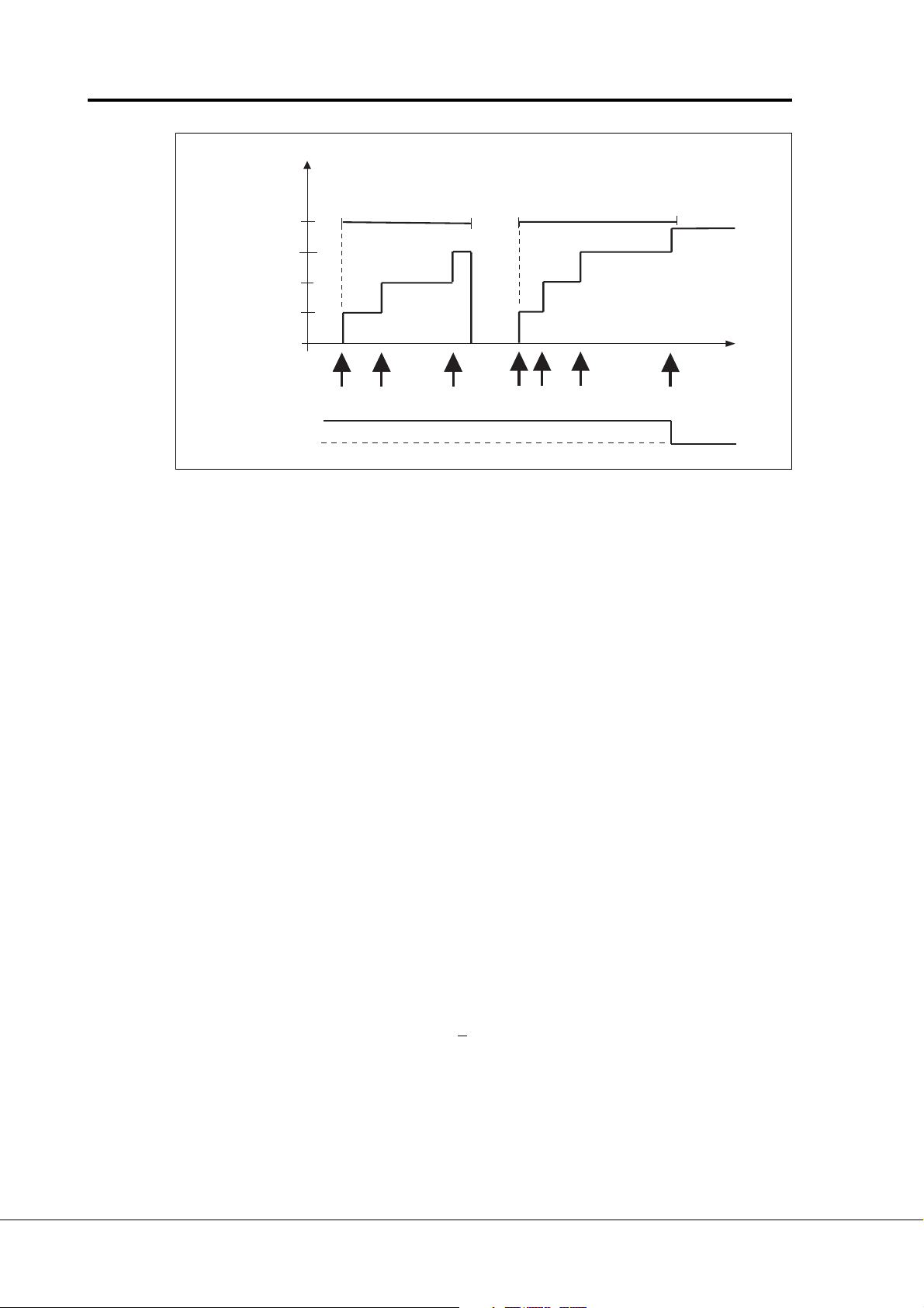
Page 44 Vacon
Pump and fan control with autochange
Number of faults
during t = t
4
3
trial
t
trial
t
trial
2
1
Three faults
RUN
STOP
Figure 6-25 Automatic restart.
8. 3 Automatic restart, start function
The parameter defines the start mode:
0 = Start with ramp
1 = Flying start, see parameter 4. 6.
8. 4 Automatic restart after undervoltage trip
0 = No automatic restart after undervoltage trip
1 = Automatic restart after undervoltage fault condition returns to the normal
condition (DC-link voltage returns to the normal level)
Par. 8. 2 = 3
t
trial
Four faults
= par. 8. 1
t
UD009K25
8. 5 Automatic restart after overvoltage trip
0 = No automatic restart after overvoltage trip
1 = Automatic restart after overvoltage fault condition returns to the normal
condition (DC-link voltage returns to the normal level)
8. 6 Automatic restart after overcurrent trip
0 = No automatic restart after overcurrent trip
1 = Automatic restart after overcurrent faults
8. 7 Automatic restart after reference fault trip
0 = No automatic restart after reference fault trip
1 = Automatic restart after analog current reference signal (4—20 mA)
returns to the normal level (
>4 mA)
8. 8 Automatic restart after over-/undertemperature fault trip
0 = No automatic restart after temperature fault trip
1 = Automatic restart after heatsink temperature has returned to its normal
level between -10°C—+75°C.
Vacon Plc Phone: +358-201 2121 Fax:+358-201 212 205
Service: +358-40-8371 150 E-mail: vacon@vacon.com
Page 45
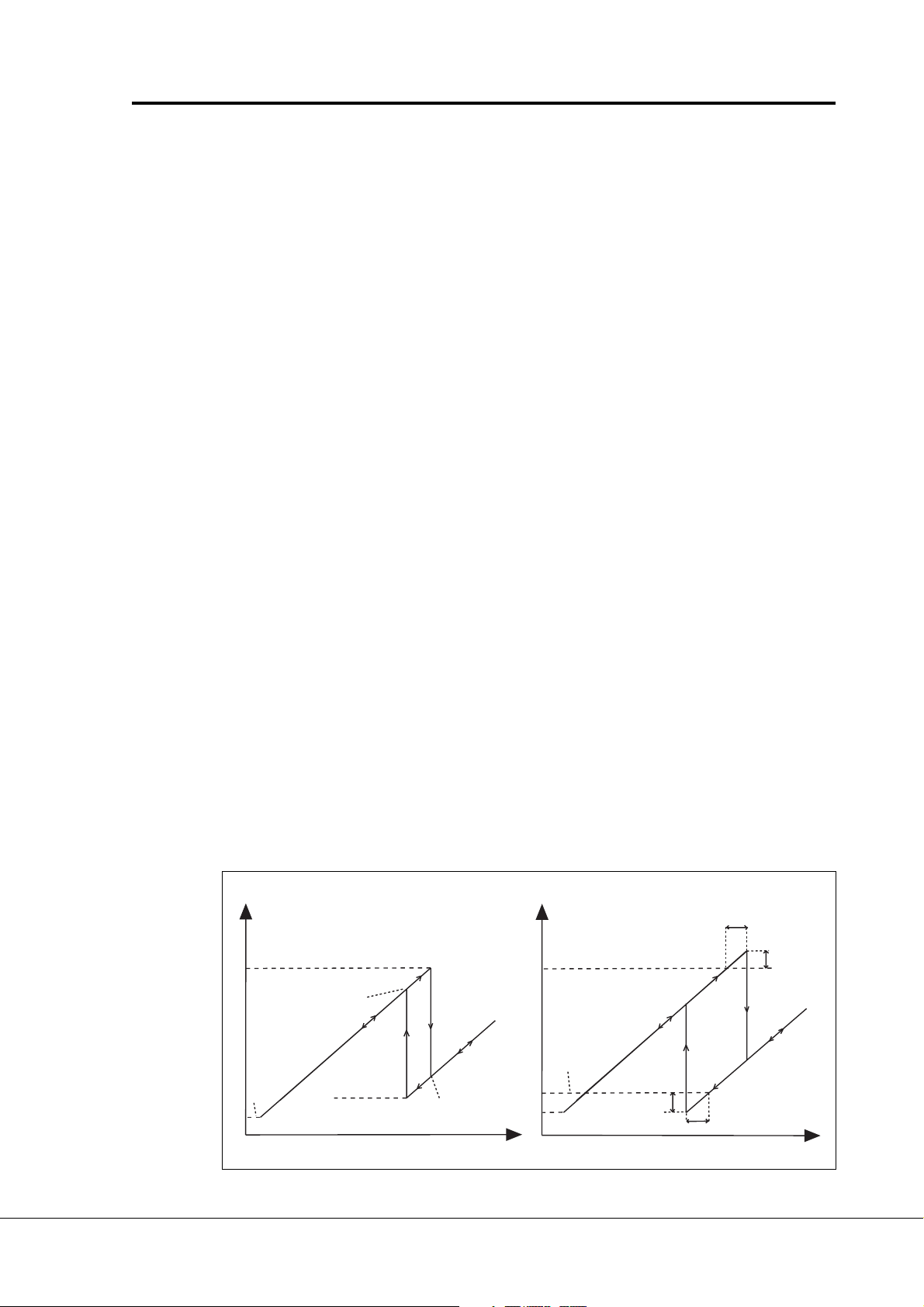
Vacon Page 45
Pump control with autochange
9. 1 Number of auxiliary drives
With this parameter the number of auxiliary drives in use will be defined. The signals
controlling the auxiliary drives on and off can be programmed to relay outputs or to
digital output with parameters 3. 6 - 3. 8. The default setting is one auxiliary drive in
use and it is pre-programmed to relay output RO1.
9. 2 Start frequency of auxiliary drive 1
9. 4 Start frequency of auxiliary drive 2
9. 6 Start frequency of auxiliary drive 3
The frequency of the drive controlled by the frequency converter must exceed the
limit defined with these parameters with 1 Hz before the auxiliary drive is started.
The 1 Hz overdraft makes a hysteresis to avoid unnecessary starts and stops. See
figure 6-26. Notice! See the parameter description par.1.1 and 1.2, page 6.
9. 3 Stop frequency of auxiliary drive 1
9. 5 Stop frequency of auxiliary drive 2
9. 7 Stop frequency of auxiliary drive 3
The frequency of the drive controlled by the frequency converter must fall with 1Hz
below the limit defined with these parameters before the auxiliary drive is stopped.
The stop frequency limit also defines the frequency to which the frequency of the
drive controlled by the frequency converter is dropped after starting the auxiliary
drive. See figure 6-26.
9. 10 Start delay of auxiliary drives
The frequency of the drive controlled by the frequency converter must exceed the
start frequency of the auxiliary drive with the time defined with parameter 9. 10 before
the drive is started. The delay is the same for all auxiliary drives. This prevents the
unnecessary starts caused by momentary start limit exceedings. See figure 6-26.
9. 11 Stop delay of auxiliary drives
The frequency of the drive controlled by the frequency converter must fall below the
stop limit of the auxiliary drive with the time defined with parameter 9. 11 before the
drive is stopped. The delay is the same for all auxiliary drives. This prevents
unnecessary stops caused by momentary falls below the stop limit. See figure 6-
26.
Output frequency
Start freq. of aux. drive 1 (par. 9.2 + 1 Hz)
Frequency after
starting the aux. drive1
is par. 9.3 - 1 Hz
Fmin
par. 1.1
Stop freq. of aux. drive 1
(par. 9.3 - 1 Hz)
Frequency after
starting the aux. drive1
is par. 9.3 + 1 Hz
Flow
Output frequency
Output frequency
Start freq. of aux. drive 1 (par. 9.2 + 1 Hz)
Stop freq. of aux.
drive 1
(par. 9.3 - 1 Hz)
Frequency decrease
during the stop delay
Fmin
par. 1.1
Start delay of the aux.
drives (par 9.10)
Stop delay of the aux.
drives (par 9.11)
Flow
Frequency
increase
during the
start delay
Figure 6-26 Example of effect of parameters in variable speed and one auxiliary
drive system.
Vacon Plc Phone: +358-201 2121 Fax:+358-201 212 205
Service: +358-40-8371 150 E-mail: vacon@vacon.com
E-mail: application.team@vacon.com
Page 46
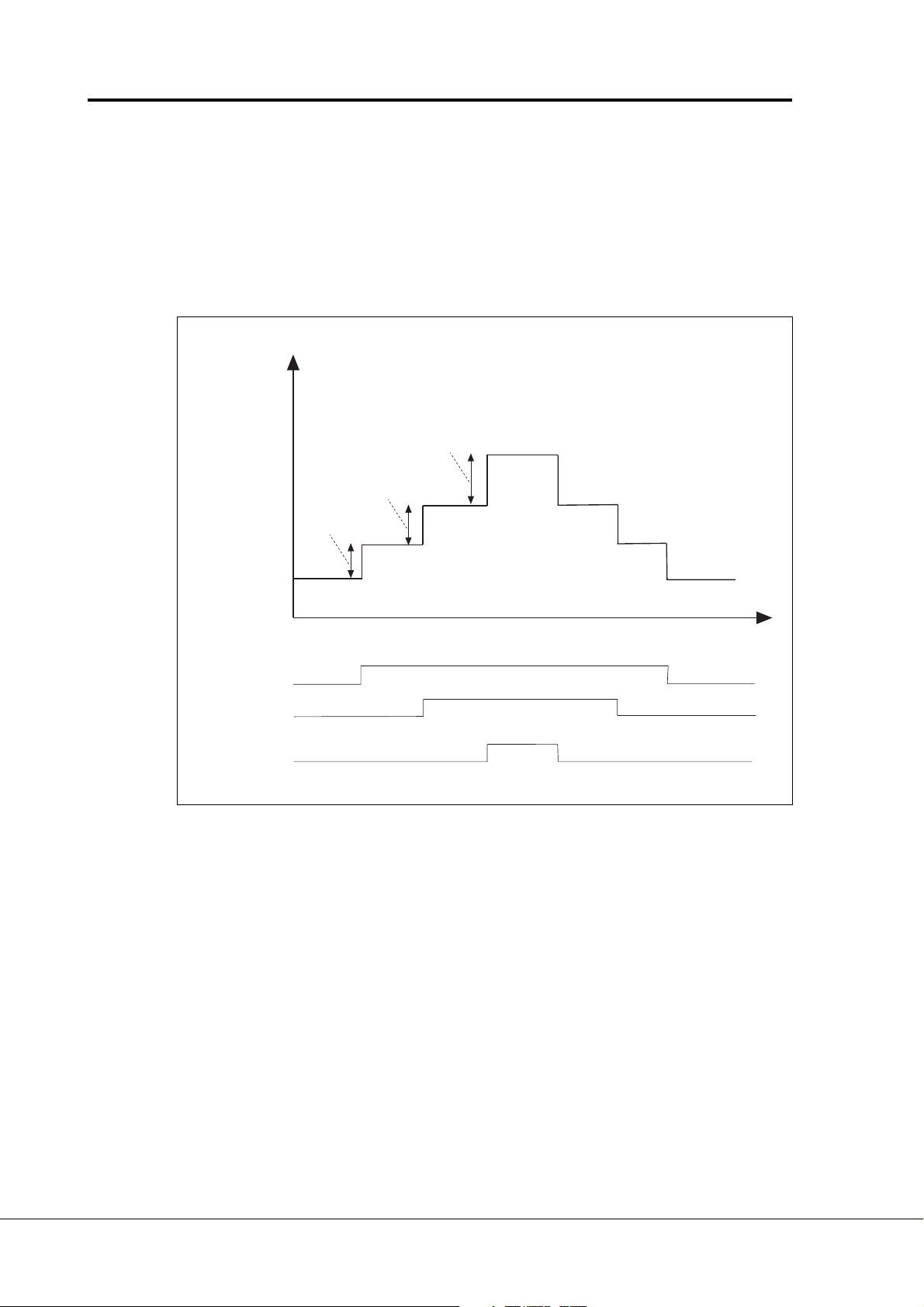
Page 46 Vacon
Pump and fan control with autochange
9. 12 Reference step after start of the auxiliary drive 1
9. 13 Reference step after start of the auxiliary drive 2
9. 14 Reference step after start of the auxiliary drive 3
9. 15 Reference step after start of the auxiliary drive 4
The reference step will be automatically added to the reference value always when
the corresponding auxiliary drive is started. With the reference steps e.g. the pressure
loss in the piping caused by the increased flow can be compensated. See figure 6-
27.
Reference for PI-controller
Reference step 3
par. 9.14
Reference step 2
par. 9.13
Reference step 1
par. 9.12
Reference
(analoginput)
start
Aux. drive 1
Aux. drive 2
Aux. drive 3
stop
start
stop
start
stop
Figure 6-27 Reference steps after starting auxiliary drives.
Time
Vacon Plc Phone: +358-201 2121 Fax:+358-201 212 205
Service: +358-40-8371 150 E-mail: vacon@vacon.com
Page 47
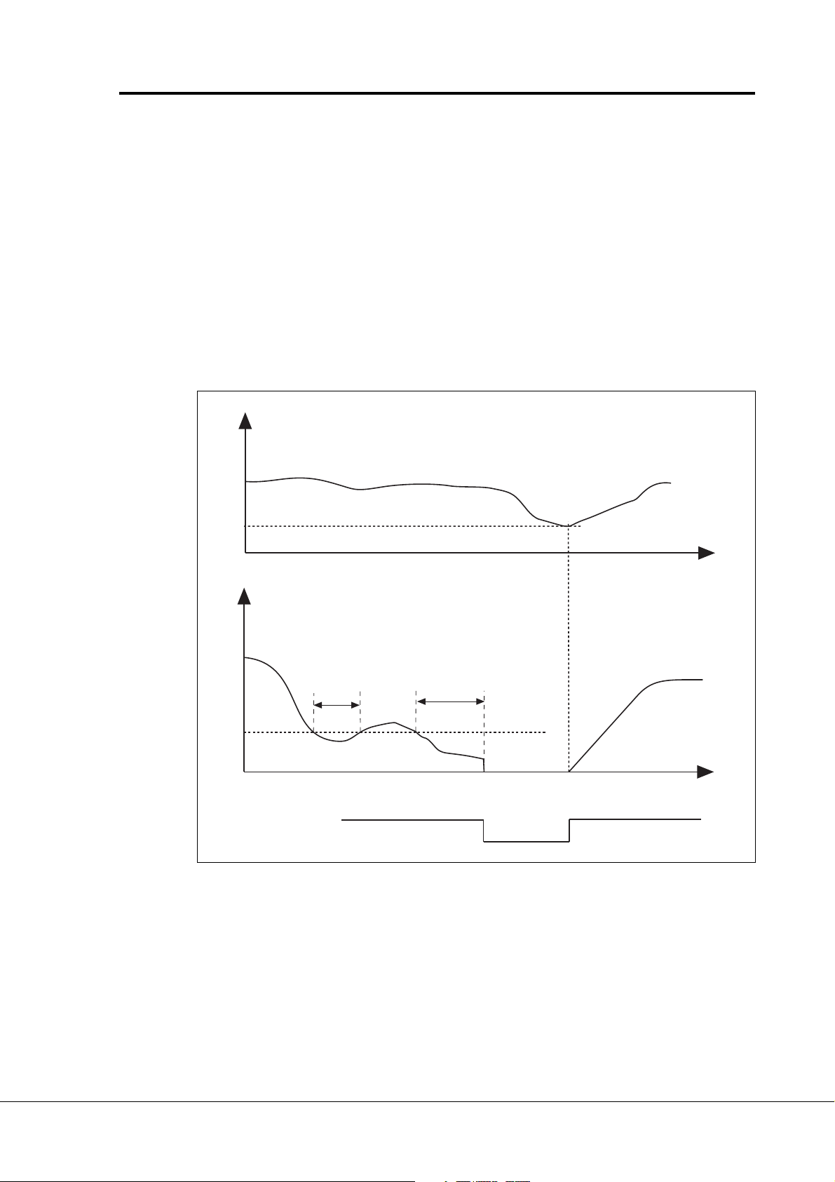
Vacon Page 47
Pump control with autochange
9. 16 Sleep level
9. 17 Sleep delay
The change of this parameter from value 0.0 Hz activates the sleep function where
the frequency converter is stopped automatically when the frequency of the drive
controlled by the frequency converter is below the sleep level (par. 9.16) continuously
for the duration of the sleep delay (9. 17). During the stop state the Pump and fan
control is operating and it turns frequency converter to Run state when the wake up
level defined with parameters 9. 18 and 9. 19 is reached. See figure 6-28.
9. 18 Wake up level
The wake up level defines the level below which the actual value must fall or which
has to be exceeded before starting the frequency converter from the sleep function.
See figure 6-28.
Actual value
Wake up level (param. 9.18 )
Output frequency
Sleep level
param. 9.16
Start/Stop status of
the var. speed drive
Figure 6-28 Example of the sleep function.
9. 19 Wake up function
t < t
sleep
(param. 9.17)
running
t
sleep
Time
Time
stop
This parameter defines if the wake up occurs when the actual value signal falls below or exceeds the wake up level. Furthermore, it shall be selected if the level (Par.
9.18) is percents of maximum value of the actual value or percents of the current
reference signal value.
Vacon Plc Phone: +358-201 2121 Fax:+358-201 212 205
Service: +358-40-8371 150 E-mail: vacon@vacon.com
E-mail: application.team@vacon.com
Page 48
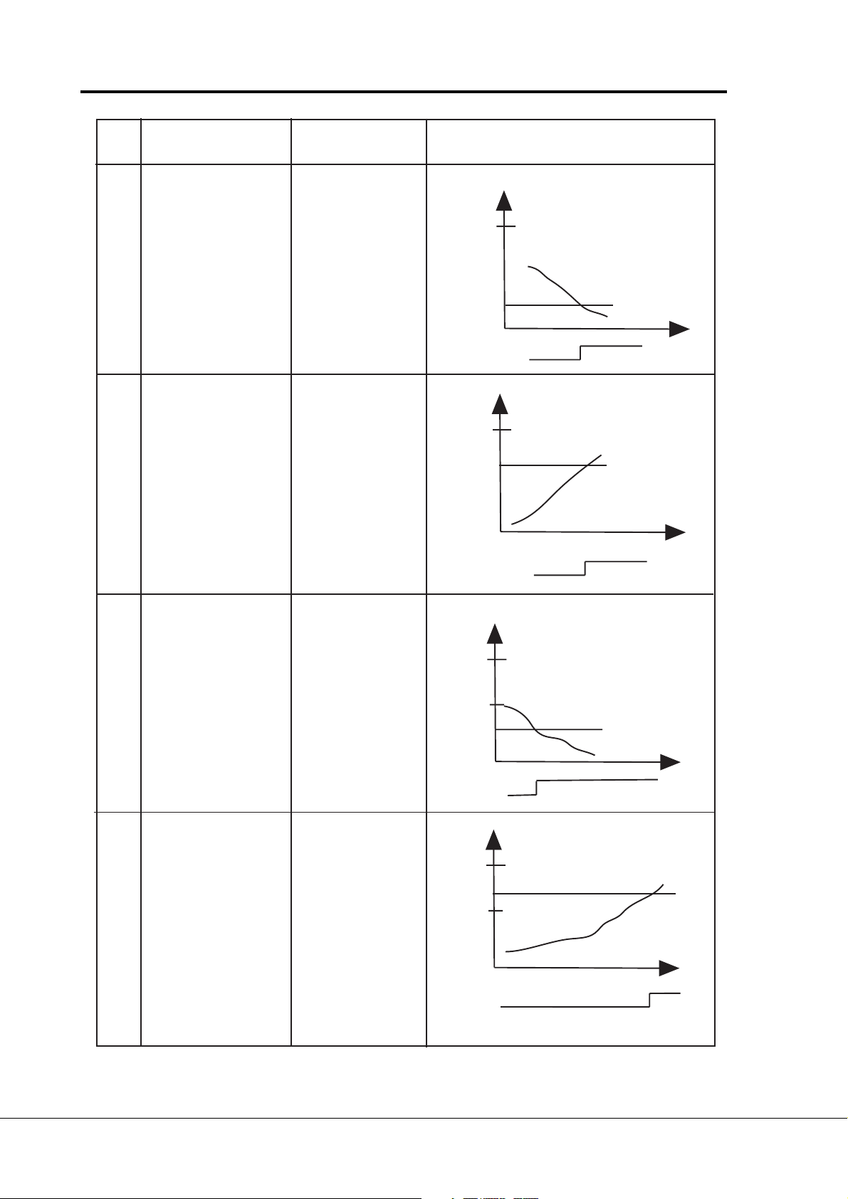
Page 48 Vacon
Pump and fan control with autochange
Par.
value
0
1
Function
Wake up happens
when actual value
goes below the
limit
Wake up happens
when actual value
exceeds the
limit
Limit
The limit defined
with parameter
9.18 is procents
from the maximum
value of the actual
value
The limit defined
with parameter
9.18 is procents
from the maximum
value of the actual
value
Description
Actual value signal
100%
Start
Stop
Actual value signal
100%
Par. 9.18=60%
Par. 9.18=30%
time
time
Wake up happens
2
when actual value
goes below the
limit
3
Wake up happens
when actual value
exceeds the
limit
The limit defined
with parameter
9.18 is procents
from the current
value of the
reference signal
The limit defined
with parameter
9.18 is procents
from the current
value of the
reference signal
Actual value signal
100%
refrence=50%
Start
Stop
Actual value signal
100%
Par.9.18=140%
limit=140%*refrence=70%
refrence=50%
Start
Stop
Par.9.18=60%
limit=60%*refrence=30%
time
time
Table 6-3 Wake up function parameter selections
Vacon Plc Phone: +358-201 2121 Fax:+358-201 212 205
Service: +358-40-8371 150 E-mail: vacon@vacon.com
Start
Stop
Page 49

Vacon Page 49
Pump control with autochange
9. 20 PI-regulator bypass
With this parameter the PI-regulator can be programmed to be bypassed. Then the
frequency of the drive controlled by the frequency converter and the starting points
of the auxiliary drives are defined according to the actual value signal.
Output freq.
Max. freq.
(par. 1.2)
Minimum freq.
(par. 1.1)
Start freq. of the aux. drive 1
(par.9.2)
Stop freq. of the aux.
drive 1 (par.9.3)
Minimum of the
actual value
Start freq. of the aux. drive 2
(par.9.4)
Stop freq. of the aux.
drive 2 (par.9.5)
Maximum of the
actual value
Actual value
Start/stop control of
the freq. converter
Auxiliary drive 1
Auxiliary drive 2
stop
start
stop
start
start
stop
Figure 6-29 Example of the function of variable speed drive and two auxiliary
drives when PI-regulator is bypassed with parameter 9. 20.
Vacon Plc Phone: +358-201 2121 Fax:+358-201 212 205
Service: +358-40-8371 150 E-mail: vacon@vacon.com
E-mail: application.team@vacon.com
Page 50

Page 50 Vacon
Pump and fan control with autochange
9. 21 Input pressure measurement analog input selection
9. 22 Input pressure high limit
9. 23 Input pressure low limit
9. 24 Output pressure drop value
In the pressure increase stations there may be need for decreasing the output
pressure if the input pressure decreases below a certain limit. The function needs
input pressure measurement that is connected to the analogue input selected with
parameter 9.21. See figure 6-30.
Vacon
CX/CXL/CXS
Input pressure
measurement
input, par 9.21
PI-controller
actual value
input par. 2.16
M
Figure 6-30 Ouput pressure decrease inputs
With parameters 9.22 and 9.23 the limits for the area of the input pressure,
where the output pressure is decreased, can be selected. Values are in
percentage of the input pressure measurement maximum value. With parameter
9.24 the value for output pressure decrease in this area can be set. The value is
percents of the reference value maximum. See Figure 6-31.
OUTPUT PRESSURE
Par. 9.24
Output
pressure
drop value
INPUT PRESSURE
TIME
Par. 9.22
Input pressure
high limit
Par. 9.23
Input pressure
low limit
Figure 6-31 Output pressure function
Vacon Plc Phone: +358-201 2121 Fax:+358-201 212 205
Service: +358-40-8371 150 E-mail: vacon@vacon.com
PUMP631.DS4
TIME
Page 51

Vacon Page 51
Pump control with autochange
9. 25 Frequency drop delay after starting an auxiliary drive
9. 26 Frequency increase delay after stopping an auxiliary drive
If the speed of auxiliary drive increases slowly (e.g. soft starter control) then a
delay (par. 9.25) between auxiliary drive start and the frequency drop of the variable speed drive will make the control smoother.
Also if the speed of the auxiliary drives decreases slowly (soft starter control)
then with parameter 9.26 a delay between auxiliary drive stop and the frequency
increase of the variable speed drive can be programmed. See figure 6-32.
If either value of parameters 9.25 and 9.26 is maximum (300,0 s) then there is
no frequency drop nor increase.
Output frequency
Aux. drive
control
Aux. drive
Aux. drive
speed
speed
Start freq. of aux drive + 1 Hz
Start delay of
aux. drive (par. 9.10)
Stop freq. of aux drive - 1 Hz
Frequency drop
delay (par. 9.25)
Stop delay of
aux. drive (par. 9.11)
vuorot4.fh3
Time
Frequency increase
delay (par. 9.26)
Figure 6-32 Frequency drop and increase delays
Vacon Plc Phone: +358-201 2121 Fax:+358-201 212 205
Service: +358-40-8371 150 E-mail: vacon@vacon.com
E-mail: application.team@vacon.com
Page 52

Page 52 Vacon
Pump and fan control with autochange
Autochange of drives
The autochange changes the start and stop order of the drives controlled by the pump- and
fan control. Also the frequency converter controlled drive can be included in the autochange
system. By using the autochange the running periods of the motors can be equal and e.g.
the stalling of the pumps because of being unused for a long period can be prevented.
The autochange can be activated by selecting the autochange mode with parameter 9.27.
The autochange happens when the time period set by parameter 9.28 is elapsed and the
level of used capacity is below the limit defined with parameters 9.29 and 9.30. During the
autochange moment all drives are stopped and then started with new order.
External contactors controlled by the relay outputs of the frequency converter connect the
drives to the mains or to the frequency converter
9. 27 Autochange mode
0 autochange not in use
1 Autochange is done by changing the starting order of the auxiliary
drives. See figure 6-33.
The frequency converter controlled drive stays same. Only the mains
contactor is needed for each drive.
Vacon
M
Aux. drive 1
M
Aux. drive 2
M
Figure 6-33 Autochange only with auxiliary drives
Vacon Plc Phone: +358-201 2121 Fax:+358-201 212 205
Service: +358-40-8371 150 E-mail: vacon@vacon.com
Page 53

Vacon Page 53
Pump control with autochange
2 Autochange with all drives
Frequency converter drive is included in the autochange. For each drive
a contactor for mains and another for frequency converter is needed. See
figure 6-34.
Vacon
auxiliary
contact
connection
Drive 1 Drive 2
M
Figure 6-34 Autochange with all drives
9. 28 Autochange interval
The parameter defines the time period after which the autochange will be done if
the used capacity is below the limit defined with parameters 9.29 and 9.30. If the
level is over the limit, wait the level to decrease below the limit before
autochange execution. The next time period counting starts from the
autochange execution. See figure 6-35.
auxiliary
contact
connection
M
Vacon Plc Phone: +358-201 2121 Fax:+358-201 212 205
Service: +358-40-8371 150 E-mail: vacon@vacon.com
E-mail: application.team@vacon.com
Page 54

Page 54 Vacon
Pump and fan control with autochange
9. 29 Autochange level, auxiliary drives
9. 30 Autochange level, variable speed drive frequency
These parameters define the level below which the used capacity must be when
the autochange happens.
* If the number of running auxiliary drives is less than the value of the parameter
9.29 the autochange can happen.
* If the number of running auxiliary drives is equal to par. 9.29 and the frequency
of the variable speed drive is less than the value of parameter 9.30 the
autochange can happen.
* If the parameter 9.30 = 0,0 Hz then the autochange can happen only in sleep
or stop state in spite of the value of parameter 9.29.
Output
frequency
Par. 9.29 = 1
Autochange level,
auxiliary drives
Autochange moment
Par. 9.30
Autochange
level, frequency
Par. 9.28
Autochange interval
Aux. drive 1
control
Aux. drive 2
control
Kuva 6-35 Autochange interval and level
Time
Par. 9.28
Autochange interval
vuorot3.fh3
Vacon Plc Phone: +358-201 2121 Fax:+358-201 212 205
Service: +358-40-8371 150 E-mail: vacon@vacon.com
Page 55

Vacon Page 55
Pump control with autochange
9. 31 Autochange interlocks
With this parameter the use of interlocks can be activated. The interlocks come
from the switches that contact motors to the automatic control (frequency converter), off-state or directly to the mains. The interlock signals are connected to
the digital inputs of the frequency converter. These inputs must be programmed
to interlock inputs. Each drive must have own interlock input.
Pump- and fan control controls only those motors whose interlock input is active.
If the interlock input changes to inactive or comes active again in Run state then
pump and fan control stops all motors and then starts control with new composition.
If the intelock of auxiliary drives comes true via RUN mode, operation depends
on par.9.35 setting. Default value is to restart the frequency converter and auxiliary
drives after STOP taking with the drives in the regulator system (dig. input =
ON). See par.9.35.
PE
L1
L2
L3
Q1
F3
F1
F2
VACON
K1
ac2maint.ds4
L1 L2 L3
UVW
M1
K1.1
PE
UVW
M
3
K2.1
K2
PE
UVW
M2
M
3
Figure 6-36 Example of two pump autochange, main diagram
Vacon Plc Phone: +358-201 2121 Fax:+358-201 212 205
Service: +358-40-8371 150 E-mail: vacon@vacon.com
E-mail: application.team@vacon.com
Page 56

Page 56 Vacon
Pump and fan control with autochange
230 VAC
25
RO2
26
K1
K2
K2.1
ac2contt.ds4
M2/mains
K1
K2
K1.1
M1/Vacon
Autom.OMains
S1
K1.1
K2
K1
M1/mains
22
RO1
23
24 VDC
VACON CX
DIA2
12
9
Autom.OMains
S2
K1
K2.1
K2
Vacon
M2/
Figure 6-37 Principal control diagram of
two-pump autochange
9. 32 Actual value special display minimum
9. 33 Actual value special display maximum
9. 34 Actual value special display, number of decimals
DIA3
10
With these parameters the minimum and maximum values and also the number
of decimals of the actual value special display can be set. The actual value can be
found on the monitoring page with signal number n26.
Minimum value (par. 9.32)
Maximum value (par. 9.33)
Figure 6-38 Actual value special display
Number of decimals (par. 9.34)
3 0. 0 0
.
.
1 0 0. 0 0
(4 mA)
(20 mA)
actspedi.fh3
Vacon Plc Phone: +358-201 2121 Fax:+358-201 212 205
Service: +358-40-8371 150 E-mail: vacon@vacon.com
Page 57

Vacon Page 57
Pump control with autochange
9.35 Interlock update
Interlock update moment is selected when the dig. input comes true during RUN mode.
0: Update after autochange interval or in STOP state (f.eg. sleep function). During START
state used drives (interlock TRUE) are taken with in the regulator system .
1: Update immediately. When the interlock comes TRUE the frequency converter and auxil-
iary drives are stopped. After this the frequency converter RERUN automatically taking with
drives of regulator system when dig. input is ON.
When dig. input is OFF interlocked drive is stopped if it is in RUN state and it is removed
from the regulator system. Frequency converter and other auxiliary drives are in RUN state.
10 Fieldbus control
Fieldbus control can be activated with parameter 10.1. Then the frequency or speed reference comes from the fieldbus as well as the Start/Stop and Reverse control.
First two parameters in group 10 concern all fieldbuses. Parameters 10.3 - 10.6 are only for
Modbus, parameters 10.7 - 10.13 only for Profibus and 10.14 only for LONWorks.
10.1 Fieldbus control
Defines the active control source:
0: control via I/O terminals
1: control via Fieldbus board
Parameters 10.2 - 10.5 only for Modbus protocol
10.2 Slave address
Defines slave device address. Maximum value for this parameter is 247 and minimum is 1.
10.3 Baud rate
1: 300 baud
2: 600 baud
3: 1200 baud
4: 2400 baud
5: 4800 baud
6: 9600 baud
7: 19200 baud
10.4 Parity type
0: None
1: Even
2: Odd
10.5 Modbus time-out
The Modbus time-out determines how long the Fieldbus board waits for a message from a
master device and is specific in seconds. Time can be set between 0 - 3600 s. Time 0 s =
No time-out.
Vacon Plc Phone: +358-201 2121 Fax:+358-201 212 205
Service: +358-40-8371 150 E-mail: vacon@vacon.com
E-mail: application.team@vacon.com
Page 58

Page 58 Vacon
Pump and fan control with autochange
Parameters 10.6 - 10.12 only for Profibus DP protocol
10.6 Profibus slave address
Defines slave device address. Maximum value for this parameter is 126 and minimum 2.
10.7 Profibus baud rate
1: 9.6 kbaud
2: 19.2 kbaud
3: 93.75 kbaud
4: 187.5 kbaud
5: 500 kbaud
6: 1.5 Mbaud
7: 3 Mbaud
8: 6 Mbaud
9: 12 Mbaud
10: AUTO (Automatic baud rate)
10.8 Profibus PPO Type
Selection of profibus PPO type.
1: PPO 1 (Parameter data 8 bytes, Control data 4 bytes)
2: PPO 2 (Parameter data 8 bytes, Control data 4 bytes)
3: PPO 3 (Control data 4 bytes)
4: PPO 4 (Control data 12 bytes)
10.9 Profibus process Data 1
10.10 Profibus process Data 2
10.11 Profibus process Data 3
10.12 Profibus process Data 4
Selection of profibus process data source.
Value 1 . . . 22 Number of actual value (=n1 . . . n22 in monitoring page).
Value 99 Active fault code.
Parameter 10.13 only for LONWorks protocol
10.14 LONWorks service button
Changing the value of tjhis parameter from 0 to 1 or vice versa and pressing the Enter
button cause the unique LONWorks ID number to be sent to the network.
Vacon Plc Phone: +358-201 2121 Fax:+358-201 212 205
Service: +358-40-8371 150 E-mail: vacon@vacon.com
Page 59

Vacon Page 59
Pump control with autochange
7 I/O-expander with pump and fan control application
The digital inputs and relay outputs of the I/O-expander board has fixed signals according to
figure 6-1 when the pump and fan control application is selected.
Digital inputs are used for interlock inputs and they all or part of them are active if the use of
interlocks is set active with parameter 9.31. Number of auxiliary drives (par, 9.1) defines
how many inputs are active. The controls of auxiliary drives are connected to relay outputs.
If four- or five-pump autochange is in use then the relay outputs of the basic control board
can be used additionally.
Terminal Signal Description
Signal from
motor termistors
201 +10V
202 Uin+ Analogue input, voltage Programmable
203 GND I/O ground Ground for reference and controls
204 I
205 Iin- range 0—20 mA (Default: Not in use)
206 +24V Control voltage output Voltage for switches, etc. max. 0.1 A
207 GND I/O ground Ground for reference and controls
208 CMC Common for DIC1-DIC7 Connect to GND or + 24 V
209 DIC1 Interlock input, Contact closed = interlock is active
210 DIC2 Interlock input Contact closed = interlock is active
211 DIC3 Interlock input, Contact closed = interlock is active
212 DIC4 Interlock input Contact closed = interlock is active
213 DIC5 Interlock input, Contact closed = interlock is active
214 DI6A+ Pulse input A
215 DI6A- (differential input)
216 DI7B+ Pulse input B 90 degrees phase shift compared
217 DI7B- (differential input) to pulse input A
218 DI8Z+ Pulse input C one pulse per one revolution
219 DI8Z- (differential input)
220 I
221 TI+ Termistor input
222 TI223 RO3 Relay output 3 Aux. drive 1 / Autochange 1 control
224 RO3
225 RO4 Relay output 4 Aux. drive 2 / Autochange 2 control
226 RO4
227 RO5 Relay output 5 Aux. drive 3 / Autochange 3 control
228 RO5
+ Analogue input, current Programmable
in
out
Reference output Voltage for a potentiometer, etc.
ref
range 0—10 V DC (Default: Not in use)
autochange 1
autochange 2
autochange 3
autochange 4
autochange 5
+ Analogue output Range 0—20 mA/RL max. 500 Ω
Programmable
Figure 7-1 I/O-expander with pump and fan control application
Vacon Plc Phone: +358-201 2121 Fax:+358-201 212 205
Service: +358-40-8371 150 E-mail: vacon@vacon.com
E-mail: application.team@vacon.com
Page 60

Page 60 Vacon
Signal from
motor termistors
Pump and fan control with autochange
Terminal Signal Description
206 +24V Control voltage output Voltage for switches, etc. max. 0.1 A
207 GND I/O ground Ground for reference and controls
208 CMC Common for DIC1-DIC7 Connect to GND or + 24 V
209 DIC1 Interlock input, Contact closed = interlock is active
autochange 1
210 DIC2 Interlock input Contact closed = interlock is active
autochange 2
211 DIC3 Interlock input, Contact closed = interlock is active
autochange 3
212 DIC4 Interlock input Contact closed = interlock is active
autochange 4
213 DIC5 Interlock input, Contact closed = interlock is active
autochange 5
214 GND I/O ground Ground for reference and controls
215 I
221 TI+ Termistor input
222 TI223 RO3 Relay output 3 Aux. drive 1 / Autochange 1 control
224 RO3
225 RO4 Relay output 4 Aux. drive 2 / Autochange 2 control
226 RO4
227 RO5 Relay output 5 Aux. drive 3 / Autochange 3 control
228 RO5
+ Analogue output Range 0—20 mA /RL max. 500 Ω
out
Programmable
Figure 7-2 I/O-Expander 103 OPT with pump and fan control
Vacon Plc Phone: +358-201 2121 Fax:+358-201 212 205
Service: +358-40-8371 150 E-mail: vacon@vacon.com
Page 61
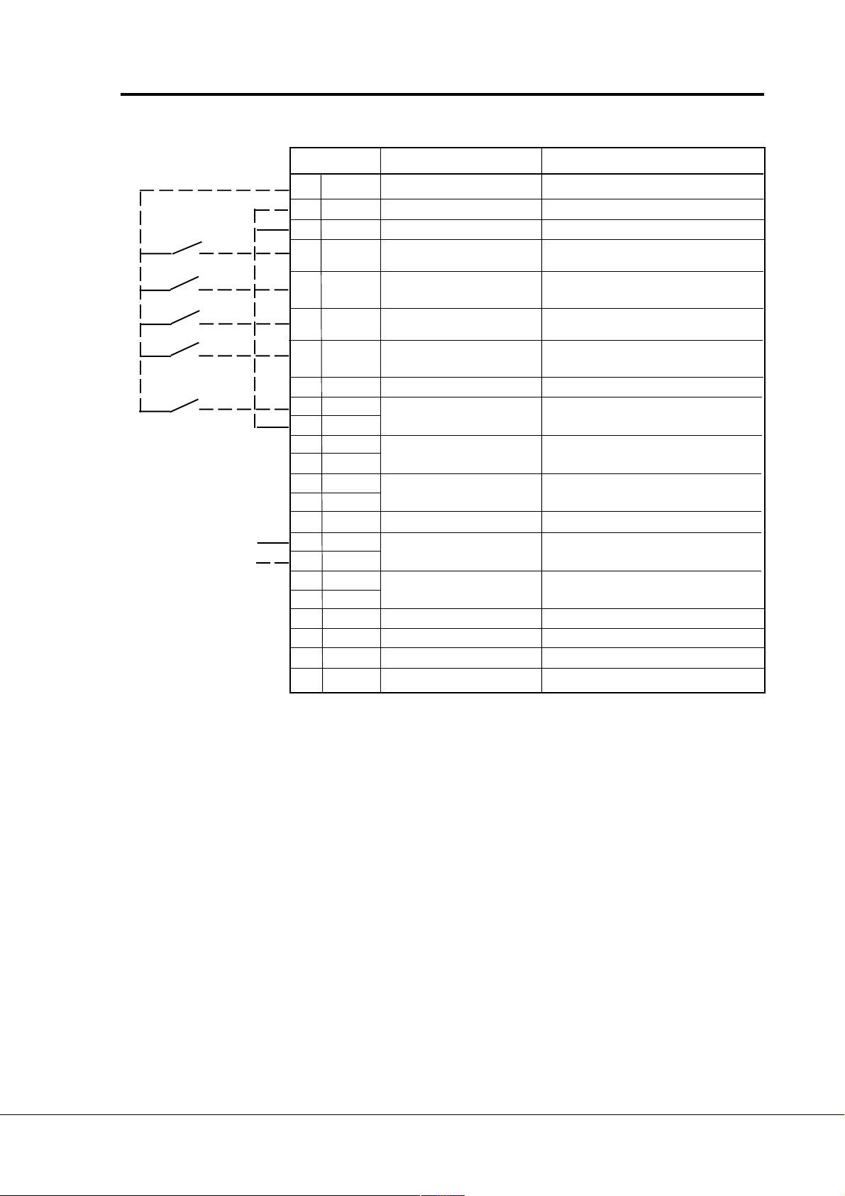
Vacon Page 61
Signal from
motor termistor
Pump control with autochange
Terminal Signal Description
206 +24V Control voltage output Voltage for switches, etc. max. 0.1 A
207 GND I/O ground Ground for reference and controls
208 COME Common for DIC1-DIC7 Connect to GND or + 24 V
209 DIE1 Interlock input, Contact closed = interlock is active
autochange 1
210 DIE2 Interlock input Contact closed = interlock is active
autochange 2
211 DIE3 Interlock input, Contact closed = interlock is active
autochange 3
212 DIE4 Interlock input Contact closed = interlock is active
autochange 4
213 Not used
214 DIE6A+ Interlock input Contact closed = interlock is active
215 DIE6A- autochange 5
216 DIE7B+
217 DIE7B218 DOE1
219 DOE2
220 Not used
221 TI+ Termistor input
222 TI225 RO4/1 Aux. drive 3 / autochange 3 control
226 RO4/2
231 DOE3 Open collector output 3 Aux. drive 1 / autochange 1 control
232 GND I/O ground
233 DOE4 Open collector output 4 Aux. drive 2 / autochange 2 control
234 GND I/O ground
Figure 7-2 I/O-Expander 202OPT with pump and fan control (Profibus)
NOTE! Termistor input (terminals 327 and 328) must be shorted if not used.
READY = ON, when mains voltage has been applied and Vacon CX is ready to operate.
RUN = ON, when motor is running.
FAULT = ON, if a fault occurs.
FIELDBUS CONTROL = ON, when the fieldbus board is the Active Control Source.
Vacon Plc Phone: +358-201 2121 Fax:+358-201 212 205
Service: +358-40-8371 150 E-mail: vacon@vacon.com
E-mail: application.team@vacon.com
Page 62

Page 62 Vacon
Signal from
motor termistor
Pump and fan control with autochange
Terminal Signal Description
301 DID1 Interlock input, Contact closed = interlock is active
autochange 1
302 DID2 Interlock input Contact closed = interlock is active
autochange 2
303 DIE3 Interlock input, Contact closed = interlock is active
autochange 3
304 DIE4 Interlock input Contact closed = interlock is active
autochange 4
305 COMD Common for DID1-DID2 Connect to GND or +24 V
306 +24 V Control voltage output Voltage for switches, etc. max. 0.1 A
307 COME Common for DIE3-DIE4 Connect to GND or +24 V
308 GND I/O ground Ground for reference and controls
309 DID5A+ Interlock input Contact closed = interlock is active
310 DID5A- autochange 5
311 DID6B+
312 DID6B313 DID7Z+
314 DID7Z315 GND I/O ground Ground for reference and controls
316 DOD1 Open collector output 1 Aux. drive 1 / autochange 1 control
317 DOD2 Open collector output 2 Aux. drive 2 / autochange 2 control
318 DOD3 Open collector output 3 Aux. drive 3 / autochange 3 control
319 DOD4 Open collector output 4 Fieldbus control
320 GND I/O ground Ground for reference and controls
327 TI+ Termistor input
328 TI-
Figure 7-3 I/O-Expander 201OPT with pump and fan control (Modbus)
NOTE! Termistor input (terminals 327 and 328) must be shorted if not used.
READY = ON, when mains voltage has been applied and Vacon CX is ready to operate.
RUN = ON, when motor is running.
FAULT = ON, if a fault occurs.
Vacon Plc Phone: +358-201 2121 Fax:+358-201 212 205
Service: +358-40-8371 150 E-mail: vacon@vacon.com
Page 63

Vacon Page 63
Signal from
motor termistor
Pump control with autochange
Terminal Signal Description
301 DID1 Interlock input, Contact closed = interlock is active
autochange 1
302 DID2 Interlock input Contact closed = interlock is active
autochange 2
303 DIE3 Interlock input, Contact closed = interlock is active
autochange 3
304 DIE4 Interlock input Contact closed = interlock is active
autochange 4
305 COMD Common for DID1-DID2 Connect to GND or +24 V
306 +24 V Control voltage output Voltage for switches, etc. max. 0.1 A
307 COME Common for DIE3-DIE4 Connect to GND or +24 V
308 GND I/O ground Ground for reference and controls
309 DID5A+ Interlock input Contact closed = interlock is active
310 DID5A- autochange 5
311 DID6B+
312 DID6B313 DID7Z+
314 DID7Z315 GND I/O ground Ground for reference and controls
316 DOD1 Open collector output 1 Aux. drive 1 / autochange 1 control
317 DOD2 Open collector output 2 Aux. drive 2 / autochange 2 control
318 DOD3 Open collector output 3 Aux. drive 3 / autochange 3 control
319 DOD4 Open collector output 4 Fieldbus control
320 GND I/O ground Ground for reference and controls
327 TI+ Termistor input
328 TI329 LONWorks network
330
Figure 7-4 I/O-Expander 203OPT with pump and fan control (LONWorks)
NOTE! Termistor input (terminals 327 and 328) must be shorted if not used.
READY = ON, when mains voltage has been applied and Vacon CX is ready to operate.
RUN = ON, when motor is running.
FAULT = ON, if a fault occurs.
Vacon Plc Phone: +358-201 2121 Fax:+358-201 212 205
Service: +358-40-8371 150 E-mail: vacon@vacon.com
E-mail: application.team@vacon.com
Page 64
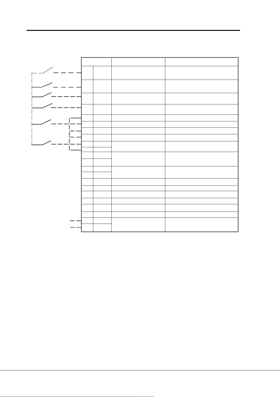
Page 64 Vacon
Signal from
motor termistor
Pump and fan control with autochange
Terminal Signal Description
301 DID1 External fault Contact open = no fault
(closing contact) Contact closed = fault
302 DID2 RUN disable Contact open=start of motor enable
Contact closed=start of motor
303 DID3 Acceler. / Decel. time Contact open = time 1 selected
selection Contact closed = time 2 selected
304 DID4 Jogging speed selection Contact open = no action
Contact closed = jogging speed
305 COMD Common for DID1-DID2 Connect to GND or +24 V
306 +24 V Control voltage output Voltage for switches, etc. max. 0.1 A
307 COME Common for DIE3-DIE4 Connect to GND or +24 V
308 GND I/O ground Ground for reference and controls
309 DID5A+ Pulse input A
310 DID5A- (differential input)
311 DID6B+ Pulse input B 90 degrees phase shift compared
312 DID6B- (differential input) to pulse input A
313 DID7Z+ Pulse input Z one pulse per one revolution
314 DID7Z- (differential input)
315 GND I/O ground Ground for reference and controls
316 DOD1 Open collector output 1 Aux. drive 1 / autochange 1 control
317 DOD2 Open collector output 2 Aux. drive 2 / autochange 2 control
318 DOD3 Open collector output 3 Aux. drive 3 / autochange 3 control
319 DOD4 Open collector output 4 Fieldbus control
320 GND I/O ground Ground for reference and controls
327 TI+ Termistor input
328 TI-
disabled
Figure 7-5 I/O-Expander 200OPT with pump and fan control (Interbus-S)
Vacon Plc Phone: +358-201 2121 Fax:+358-201 212 205
Service: +358-40-8371 150 E-mail: vacon@vacon.com
Page 65

Vacon Page 65
Pump control with autochange
PE
L1
L2
L3
Q1
F3
F1
F2
F2
VACON
ac3maint.ds4
K1
L1 L2 L3
UVW
M1
K1.1
K2
PE
UVW
M
3
M2
K2.1
UVW
M
3
K3
PE
M2
Figure 7-6 Example of 3-pump autochange system, main diagram
230 VAC
K3.1
PE
UVW
M
3
K1
K3
K2
K1.1
M1/Vacon
S1
AOV
K1.1
K2
K1
M1/mains
223
224
K3
24 VDC
206
209
AOV
S2
K3
K1
K2.1
K2
Vacon
M2/
K2.1
K1
K2
M2/mains
225
226
K3
VACON I/O-expander
210
K3
K2
K3.1
K3
M3/Vacon
Figure 7-7 Principal control diagram of 3-pump autochange system
Vacon Plc Phone: +358-201 2121 Fax:+358-201 212 205
Service: +358-40-8371 150 E-mail: vacon@vacon.com
E-mail: application.team@vacon.com
S3
AOV
K3.1
K2
K3
M3/mains
227
228
K1
212
ac3contt.ds4
Page 66

Page 66 Vacon
Pump and fan control with autochange
8 Commissioning of pump- and fan control application
General
1. Set motor name plate data, supply voltage and other parameters if necessary.
2. Set the number of auxiliary drives
3. If needed change the start and stop limits of the auxiliary drives as well as start
and stop delays of auxiliary drives
Autochange not in use
4A. Program the relay outputs and digital output according to the number of auxiliary
drives. Set own output for each drive with parameters 3.6 - 3.8.
The value of the parameter will be Aux. drive 1, Aux. drive 2 or Aux. drive 3
Autochange in use
4B. Program the relay outputs and digital output according to the number of auxiliary
drives by setting values of parameters 3.6 - 3.8 to:
3.6 = Autochange 3 control (27) , Digital output
3.7 = Autochange 1 control (26) , Relay output 1
3.8 = Autochange 2 control (26) , Relay output 2
If the Autochange is only with auxiliary drives (par. 9.27 =1) then the outputs are
auxiliary drive control signals. In the beginning the Autochange 1 control is the
control signal of the first auxiliary drive.
If all drives are included to the autochange (par. 9.27 = 2) then the outputs are
control signals of the frequency converter controlled drive and auxiliary drives. In
the beginning the Autochange 1 control is the control signal of the frequency
converter controlled drive
5B. Program the autochange interval (par. 9.28) and proper capacity level (par. 9.29
and par 9.30) that can be in use when the Autochange happens.
6B. If interlocks are used then set the function active with parameter 9.31. Program
own interlock input for each drive. If I/O-expander is in use it has interlock inputs
as constant and the inputs of basic control board are not needed.
Vacon Plc Phone: +358-201 2121 Fax:+358-201 212 205
Service: +358-40-8371 150 E-mail: vacon@vacon.com
Page 67

Vacon Page 67
Pump control with autochange
9 MONITORING DATA
The PI-control application has extra items for monitoring (V20 - V26). See table 9-1
Data Data Unit Description
number name
V1 Output frequency Hz Frequency to the motor
V2 Motor speed rpm Calculated motor speed
V3 Motor current A Measured motor current
V4 Motor torque % Calculated actual torque/nominal torque of the unit
V5 Motor power % Calculated actual power/nominal power of the unit
V6 Motor voltage V Calculated motor voltage
V7 DC-link voltage V Measured DC-link voltage
V8 Temperature °C Temperature of the heat sink
V9 Operating day counter DD.dd Operating days 1), not resettable
V10 Operating hours, HH.hh Operating hours 2), can be reset with
"trip counter" programmable button #3
V11 MW-hours MWh Total MW-hours, not resettable
V12 MW-hours, MWh MW-hours, can be reset with programmable
"trip counter" button #4
V13 Voltage/analogue input V Voltage of the terminal Uin+ (term. #2)
V14 Current/analogue input mA Current of terminals Iin+ and Iin- (term. #4, #5)
V15 Digital input status, gr. A
V16 Digital input status, gr. B
V17 Digital and relay output
status
V18 Control program Version number of the control software
V19 Unit nominal power kW Shows the power size of the unit
V20 PI-controller reference % Percents of the maximum reference
V21 PI-controller actual value % Percents of the maximum actual value
V22 PI-controller error value % Percents of the maximum error value
V23 PI-controller output Hz
V24 Number of running
auxiliary drives
V25 Motor temperature rise % 100%= temperature of motor has risen to nominal
V26 Actual value special Minimum and maximum values and number of
display decimals is defined with parameters 9.32 - 9.34
V27 Digital input OPT 1 - 3 See V15, V16, V17
V28 Digital input OPT 4 - 5 See V15, V16, V17
V29 Digital and relay output OPT See V15, V16, V17
Table 9-1 Monitored items.
Vacon Plc Phone: +358-201 2121 Fax:+358-201 212 205
Service: +358-40-8371 150 E-mail: vacon@vacon.com
E-mail: application.team@vacon.com
1)
DD = full days, dd = desimal part of a day
2)
HH = full hours, hh = desimal part of an hour
Page 68

Page 68 Vacon
Pump and fan control with autochange
10 Panel reference
The Pump and fan control application has extra references (r2 and r3) for PI-controller on the
panel's reference page. See table 10-1.
Reference reference range step Function
number name
r1 Frequency f
min—fmax
0.01 Hz Reference for panel control and
reference I/O terminal Source B reference.
r2 PI-controller 0—100% 0.1% Reference for PI-controller
reference
r3 PI-controller 0—100 % 0,1 % Reference for PI-controller
reference - Can be programmed to PI-
controller reference 2 that can be
selected with digital input.
Table 10-1 Panel reference.
Vacon Plc Phone: +358-201 2121 Fax:+358-201 212 205
Service: +358-40-8371 150 E-mail: vacon@vacon.com
Page 69

Vacon Page 69
Pump control with autochange
Remarks:
Vacon Plc Phone: +358-201 2121 Fax:+358-201 212 205
Service: +358-40-8371 150 E-mail: vacon@vacon.com
E-mail: application.team@vacon.com
Page 70

D 00178G, 12.4.2001
U
Distributor:
VA CON PLC
P.O. Box 25
Runsorintie 7
FIN-65381 VAASA
FINLAND
Phone: +358-201 2121
Fax: +358-201-212 205
Service: +358-40-8371 150
E-mail: vacon@vacon.com
http://www.vacon.com
 Loading...