

Page 1

USER'S MANUAL
Interbus-S
Fieldbus
Option Board
VACON CX / CXL
Frequency
Subject to changes without notice
Converter
Page 2

VACON CX Interbus-S user’s manual
_________________________________________________________________________________________
INDEX
1. GENERAL....................................................................................................................................................... 3
1. SPECIFICATIONS.......................................................................................................................................... 4
1. INTERBUS-S .................................................................................................................................................. 5
4. INSTALLATION.............................................................................................................................................. 7
5. CONNECTIONS.................................................................................................................................................. 9
5.1 Board layout ............................................................................................................................................... 9
5.2 Interbus-S connections ............................................................................................................................ 10
5.3 /O-control connections ................................................................................................................................. 11
6. COMMISSIONING ............................................................................................................................................ 12
7. DRIVECOM................................................................................................................................................... 13
7.1 Device control State machine .................................................................................................................. 13
7.2 Profile Parameters ................................................................................................................................... 15
7.2.1 Process Input Data Description (6000HEX) .................................................................................... 16
7.2.2 Process Output Data Description (6001HEX) ................................................................................. 16
7.2.3 Process Output Data Enable (6002HEX) ........................................................................................ 17
7.2.4 Connection Abort Option Code (6007HEX).....................................................................................17
7.2.5 Malfunction code (603Fhex) ............................................................................................................ 18
7.2.6 Control Word (6040hex).................................................................................................................. 19
7.2.7 Nominal Speed (6042hex)............................................................................................................... 21
7.2.8 Speed Reference Variable (6043hex) ............................................................................................. 21
7.2.9 Actual Speed (6044hex) .................................................................................................................. 21
7.2.10 Speed Min Max Amount (6046hex) ................................................................................................. 22
7.2.11 Speed Acceleration (6048hex) ........................................................................................................ 22
7.2.12 Speed Deceleration (6049hex)........................................................................................................ 23
7.2.13 Face Value Factor (604Bhex) ......................................................................................................... 24
Page
2
8. VACON PARAMETERS ................................................................................................................................... 25
8.1 Monitoring variables ................................................................................................................................. 25
8.2 Parameter Write....................................................................................................................................... 26
8.3 Parameter read ........................................................................................................................................... 27
9. PCP-COMMUNICATION SERVICES .............................................................................................................. 28
9.1 Initiate....................................................................................................................................................... 28
9.2 Abort......................................................................................................................................................... 28
9.3 Status ....................................................................................................................................................... 28
9.4 Identify...................................................................................................................................................... 29
9.5 Get OV ..................................................................................................................................................... 29
9.6 Read......................................................................................................................................................... 29
9.7 Write......................................................................................................................................................... 29
10. EXTRA INFORMATION.................................................................................................................................. 30
_________________________________________________________________________________________
Vacon Plc Phone +358-201 2121 Fax: +358-201 212 205
Page 3
VACON CX Interbus-S user’s manual
_________________________________________________________________________________________
Page
3
1. GENERAL
Vacon frequency converters can be connected to Interbus-S fieldbus by using fieldbus board. The
converter can be then controlled, monitored and programmed from the Host system. Fieldbus board
follows connection profile 21 for frequency converters defined by DRIVECOM user’s group. This
guarantees that interfacing of the Vacon frequency converter to the Interbus-S fieldbus happens
according to the standardized parameters and functions. Then the commissioning of the frequency
converter speed up and control of the frequency converter facilitated. Vacon Fieldbus board is a remote
bus device.
The used I/O can be also extended by the Fieldbus board:
• 4 digital inputs (standard signals)
• 4 digital outputs (standard signals)
• Termistor input (can be directly connected into the motor termistors for over temperature trip)
• Encoder input
Fieldbus board can be installed into the existing option board place inside the frequency converter.
The control connections are isolated from the mains potential and I/O ground is connected to the frame
of the device via an 1 MΩ resistor and 4.7 nF capacitor*. The control I/O ground can be connected also
directly to the frame by changing the position of the jumper X9 (GND ON/OFF) to ON-position. Digital
inputs are also isolated from the I/O ground.
Internal components and circuit boards (except the isolated I/O terminals) are at mains
potential when the Vacon CX/CXL is connected to the mains. This voltage is extremely
dangerous and may cause death or severe injury if you come in contact with it.
The control I/O terminals are isolated from the mains potential, but the I/O:s (if jumper X9 is in
OFF position) may have dangerous voltage connected even if the power is off on the Vacon
CX/CXL.
* Default value (X9 is GND OFF- position)
_________________________________________________________________________________________
Vacon Plc Phone +358-201 2121 Fax: +358-201 212 205
Page 4
VACON CX Interbus-S user’s manual
Page
4
_________________________________________________________________________________________
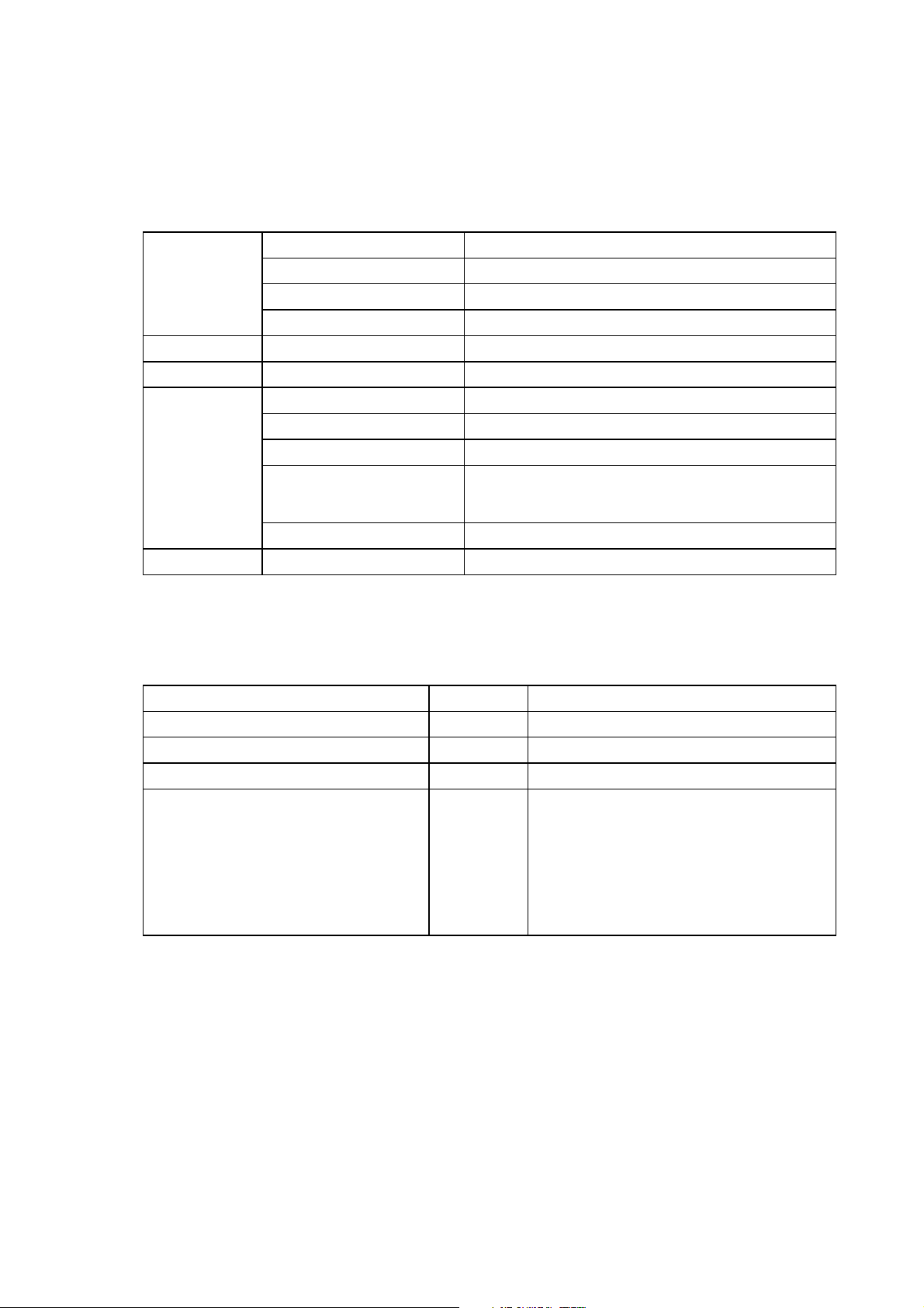
1. SPECIFICATIONS
IBS -
connections
I/O -control
connections
Safety
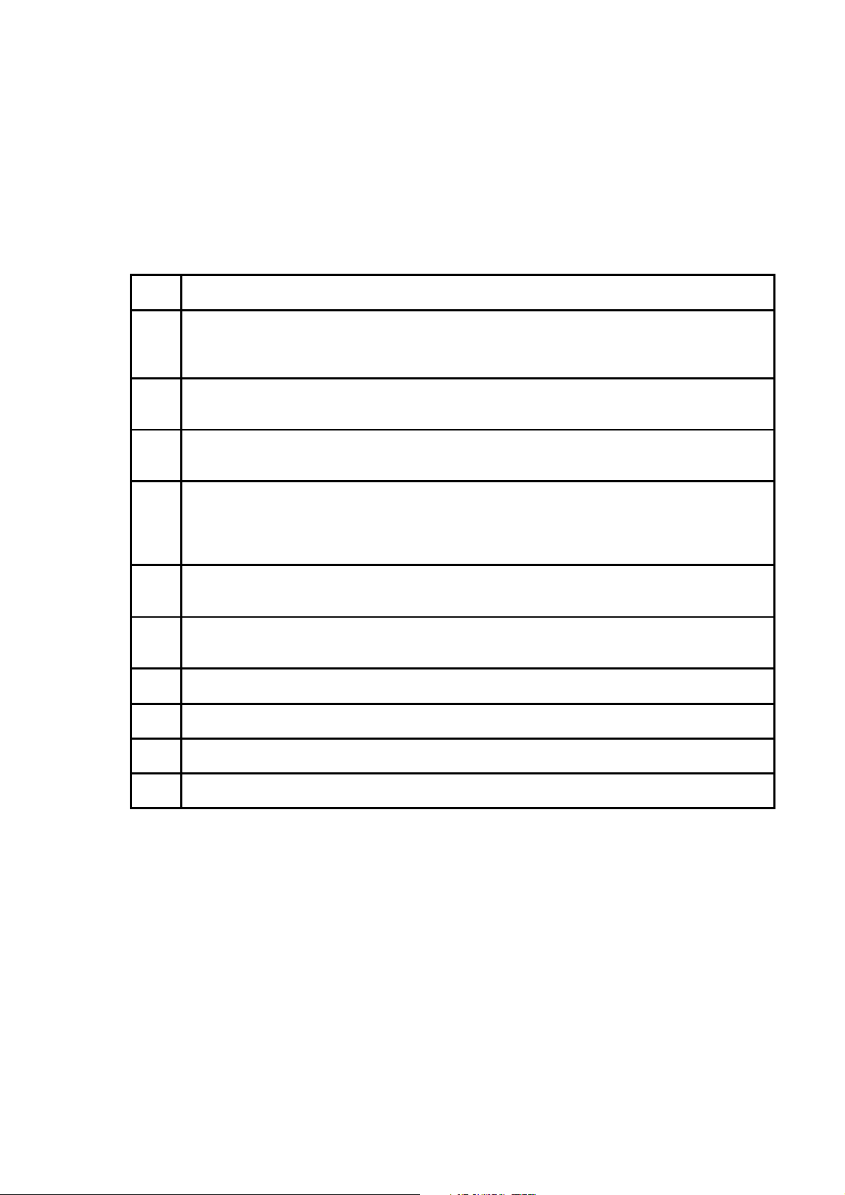
Table 1. Specifications
Interface Remote bus, 9-pin DSUB connector
Transfer method RS-485
Transfer cable Twisted pair (2 pair and ground)
Electrical isolation
- Remote bus in 500 V DC
Digital input (4 pcs)
24 V (± 15 %), R
= 5 kΩ
i
Digital output (4 pcs) Open collector output, 50 mA/48 V
Termistor input (1 pcs)
Encoder input (3 pcs)
Aux. voltage
= 4.7 kΩ
R
trip
24 V (± 30 V): “0” ≤10 V, “1” ≥18 V, R
5 V (± 10 V): “0” ≤2 V, “1” ≥3 V, R
i
24 V (±20%), max 50 mA
Fulfils EN50178 standard
= 3.3 kΩ
i
= 330 Ω
ID - Code
Profile
Process Data
PCP communication
Communication Reference List
- max. PDU length for Sending -high
- max. PDU length for Sending.-low
- max. PDU length for Receive -high
- max. PDU length for Receive -low
- supported services Client
- supported services Server
Table 2. Interbus-S communication data
227 Remote bus station with PCP
21 DRIVECOM
2 words
1 word
0 bytes
64 bytes
0 bytes
64 bytes
00 00 00
00 30 80
Read, Write, Information Report
_________________________________________________________________________________________
Vacon Plc Phone +358-201 2121 Fax: +358-201 212 205
Page 5
VACON CX Interbus-S user’s manual
_________________________________________________________________________________________
Page
5
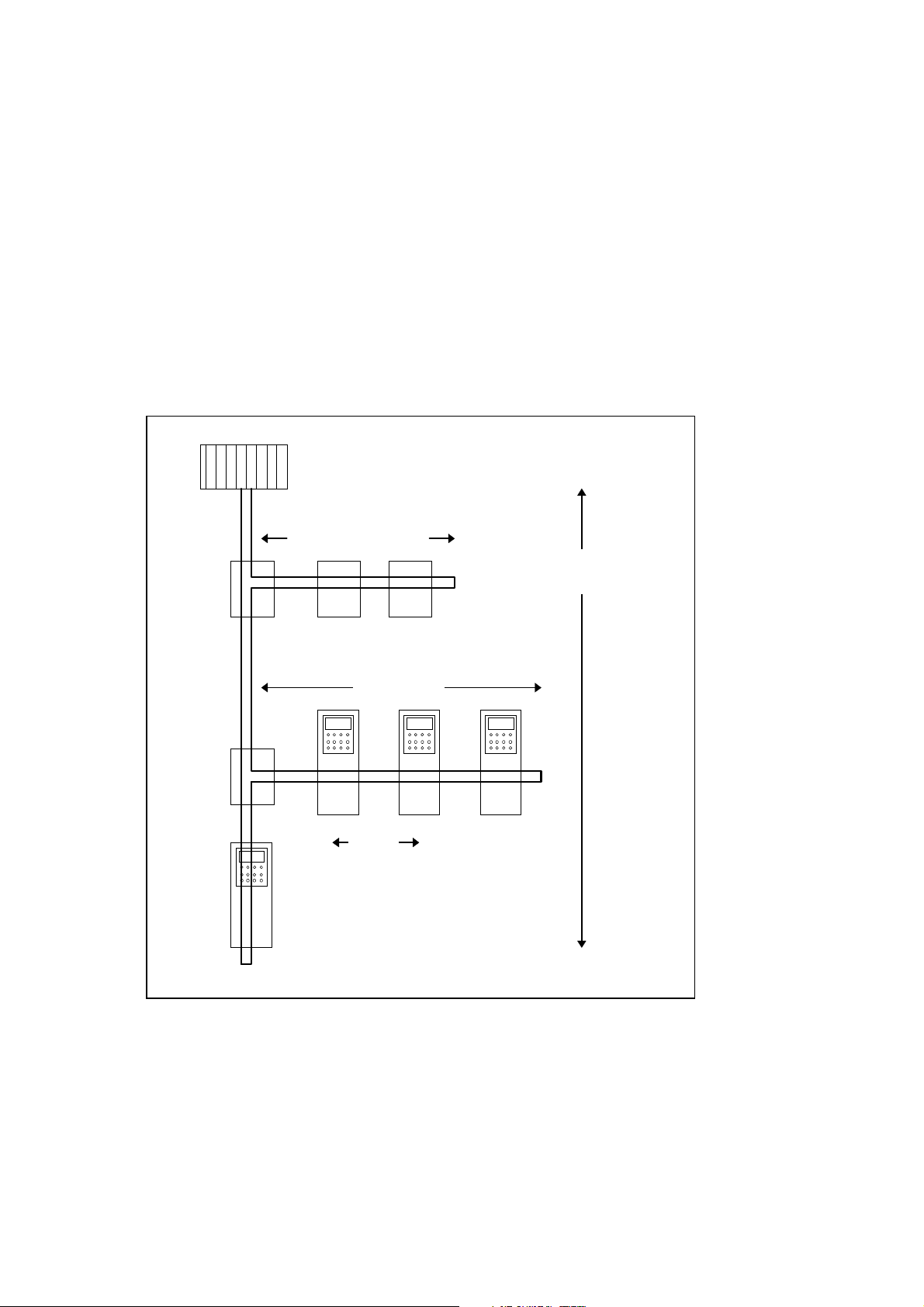
1. INTERBUS-S
Interbus-S is fast sensore/actuator fieldbus. Through Interbus-S fieldbus both individual I/O-device and
intelligent actuator can be controlled, such as frequency converter. Due to topology Interbus-S is able to
fast, under 10 ms, response times.
Interbus-S is from it’s topology a ring, where is one Host system. As a Host system can function for
example a programmable logic, industrial design PC or process station of the automation system.
Remote bus cable which begins from Host System combines the Bus terminals of the field. The long
displacements in the field are implemented by using Remote bus. If Bus terminal in the field does not
include repeat function, it will be connected to Interbus-S fieldbus by using Local bus. Local bus situated
in the field is local, switch cabinet’s internal bus, which is however a part of the Interbus-S circle. Vacon
equipped with Fieldbus board is Remote bus device.
Host System
Bus
terminal
Bus
terminal
Local bus
8 station 10 m
Remote bus
13 km
Remote bus
400 m
Figure 1. Interbus-S topology
_________________________________________________________________________________________
Vacon Plc Phone +358-201 2121 Fax: +358-201 212 205
Page 6
VACON CX Interbus-S user’s manual
Status Word
Sp
p
Page
6
_________________________________________________________________________________________
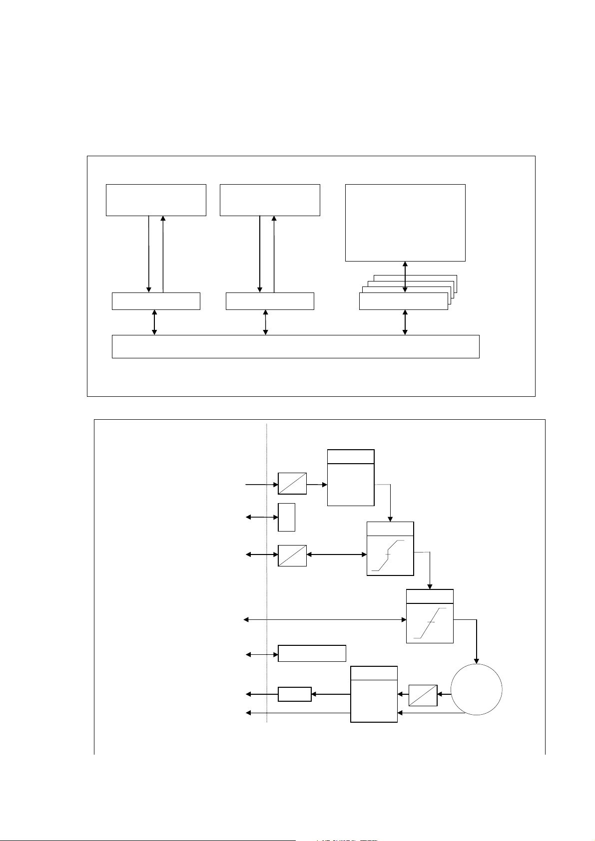
Information can be deliver two ways to the device, which is in the Interbus-S field. The Process channel
is used for the fast information delivery. With the support of this channel can be for example speed
reference of the frequency converter placed and get back the actual speed information. Slower, but
more information included parameter information delivery PCP channel is used (Peripheral
Communication Protocol), when message construction according to DRIVECOM Profile 21 is used.
Nominal Speed
Actual Value Speed
Control Word
Status Word
Speed Min Max Amount
Speed Acceleration
Speed Deceleration
Face Value Factor
.
.
Process channel 1 Process channel 2 PCP channel
DRIVE
Figure 2. Process channel/PCP channel
Connection of Vacon frequency converter to the Interbus-S field is described in the interface figure
below:
DRIVEMASTER
SCALE 1
a
X * -----
Nominal
rpm
b
Face Value
a
b
LIMIT
eed Min Max
Speed
Control Word
Actual Value Speed
Speed Reference
rpm
- Sli
State
SCALE 2
b
X * -----
a
RAMP
rpm
M
3 ~
Figure 3. Drivecom interface
_________________________________________________________________________________________
Vacon Plc Phone +358-201 2121 Fax: +358-201 212 205
Page 7
VACON CX Interbus-S user’s manual
_________________________________________________________________________________________
Page
7
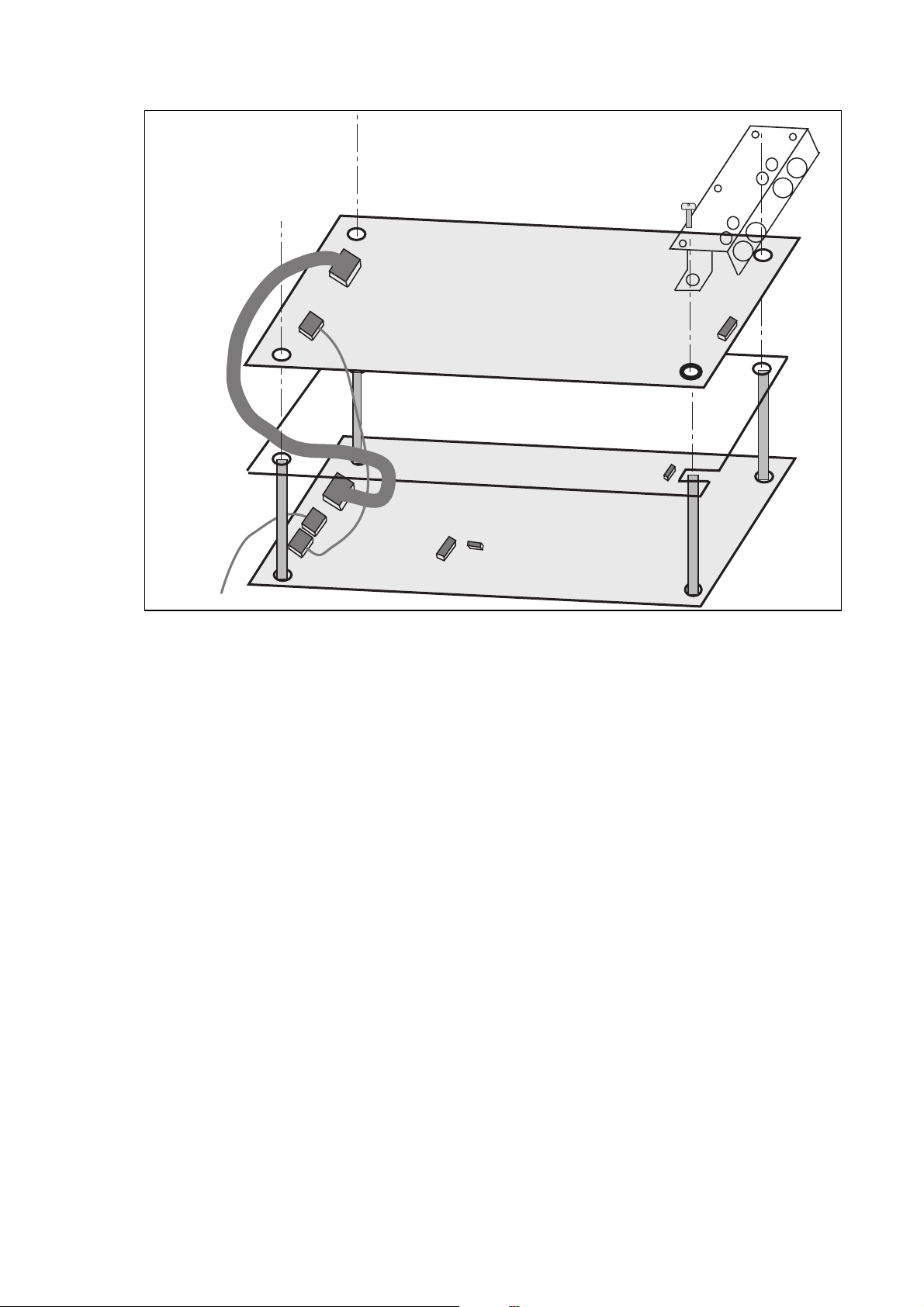
4. INSTALLATION
Before doing any commissioning actions read carefully safety instructions from the "User's manual
CX/CXL/CXS frequency converter"- manual chapter 2. Check that you have got all the Fieldbus board
parts: Fieldbus board, plastic board, power cable (black terminal), data cable (blue terminal) and
earthing screw.
Fieldbus board can be installed into the existing option board place inside the frequency converter (see
figure 4-1).
Remove the control panel and the jumper X4 from the control board (1).
A
Install the power cable into the control board X5 -terminal (2) and data cable to the X14 -
B
terminal (3). Power cable can also be installed into the X6 -terminal, if the power cable from
the power board is connected into the X5 -terminal.
Bend the data cable to the "S-curve" as far as possible from the power board transformer
C
(4) before you install the plastic board into the control board.
Remove the protection foil of the plastic board and install the plastic board into the control
D
board, remember the right position of the plastic board (5).
Install the Fieldbus board into the plastic board from the larger holes and "push" it into the
E
right position in the narrow position of the screws . Check that the Fieldbus board is installed
stable. If you have difficulties to place the plastic board and Fieldbus board, bend slightly the
regulator A4 (6) and capasitor C59 (7) of the control board.
Install the power cable to the X6 -terminal of the Fieldbus board (8)and data cable to the
F
X14 -terminal (9).
Install the jumper which you remove from the X4 -terminal of the control board, into the X9 -
G
terminal of the Fieldbus board (10) ON or OFF position.
If the packet includes the cable cover (11), install that into position shown in figure 1.
H
Install the earthing screw (12).
I
After this install the control panel and connect the needed control signals.
J
If use 5 V encoder input, install the jumper to the X7-terminal (see Chapter 5, figure 1) of the
K
Fieldbus board.
_________________________________________________________________________________________
Vacon Plc Phone +358-201 2121 Fax: +358-201 212 205
Page 8
VACON CX Interbus-S user’s manual
_________________________________________________________________________________________
Page
8
11
12
9
Fieldbus board
8
10
4
Plastic board
5
6
3
2
Figure 1. Fieldbus board installed into the control board
Control board
7
1
_________________________________________________________________________________________
Vacon Plc Phone +358-201 2121 Fax: +358-201 212 205
Page 9
VACON CX Interbus-S user’s manual
Page
9
_________________________________________________________________________________________
5. CONNECTIONS
5.1 Board layout
Terminals:
X10
TR
RD
BA
RC
UL
X11
X7
Extra terminal
X10 I/O - terminals
X11 Termistor input
X7 Encoder terminal
X5 Interbus-S Input
X6 Interbus-S Output
X6
X5
D-sub connectors
Figure 1. Fieldbus board
UL Supply Voltage, Green.
UL led is active if the interface board has supply voltage.
RC Remote bus Check, Green.
RC led is active if the cable connection is good and the Interbus-S master is not
reset.
BA Bus Active, Green.
RD Remote bus Disabled, Red.
The red RD led is active if the outgoing remote bus is disabled.
TR Transmit/Receive, Green.
PCP communication is active.
_________________________________________________________________________________________
Vacon Plc Phone +358-201 2121 Fax: +358-201 212 205
Page 10

VACON CX Interbus-S user’s manual
Page
10
_________________________________________________________________________________________
5.2 Interbus-S connections
Input (male):
Signal Connector
D SUB 9-pin
12345
9876
Board Connector
X5 - terminal
Description
DO 1 X5 - 1 Data Out
DI 2 X5 - 3 Data In
COM 3 X5 - 5 Common
/DO 6 X5 - 2 Data Out, Inverse
/DI 7 X5 - 4 Data In, Inverse
Shield X5 - 10 Cable shield
Table 1. Input D-sub connector
Output (female):
9876
Signal Connector
D SUB 9-pin
12345
Board Connector
X6 - terminal
Description
DO 1 X6 - 1 Data Out
DI 2 X6 - 3 Data In
COM 3 X6 - 5 Common
+ 5V 5 X6 - 9
/DO 6 X6 - 2 Data Out, Inverse
/DI 7 X6 - 4 Data In, Inverse
RBST 9 X6 - 8 Remote Bus Connector
Shield X6 - 10 Cable shield
Table 2. Output D-sub connector
_________________________________________________________________________________________
Vacon Plc Phone +358-201 2121 Fax: +358-201 212 205
Page 11

VACON CX Interbus-S user’s manual
Page
11
_________________________________________________________________________________________
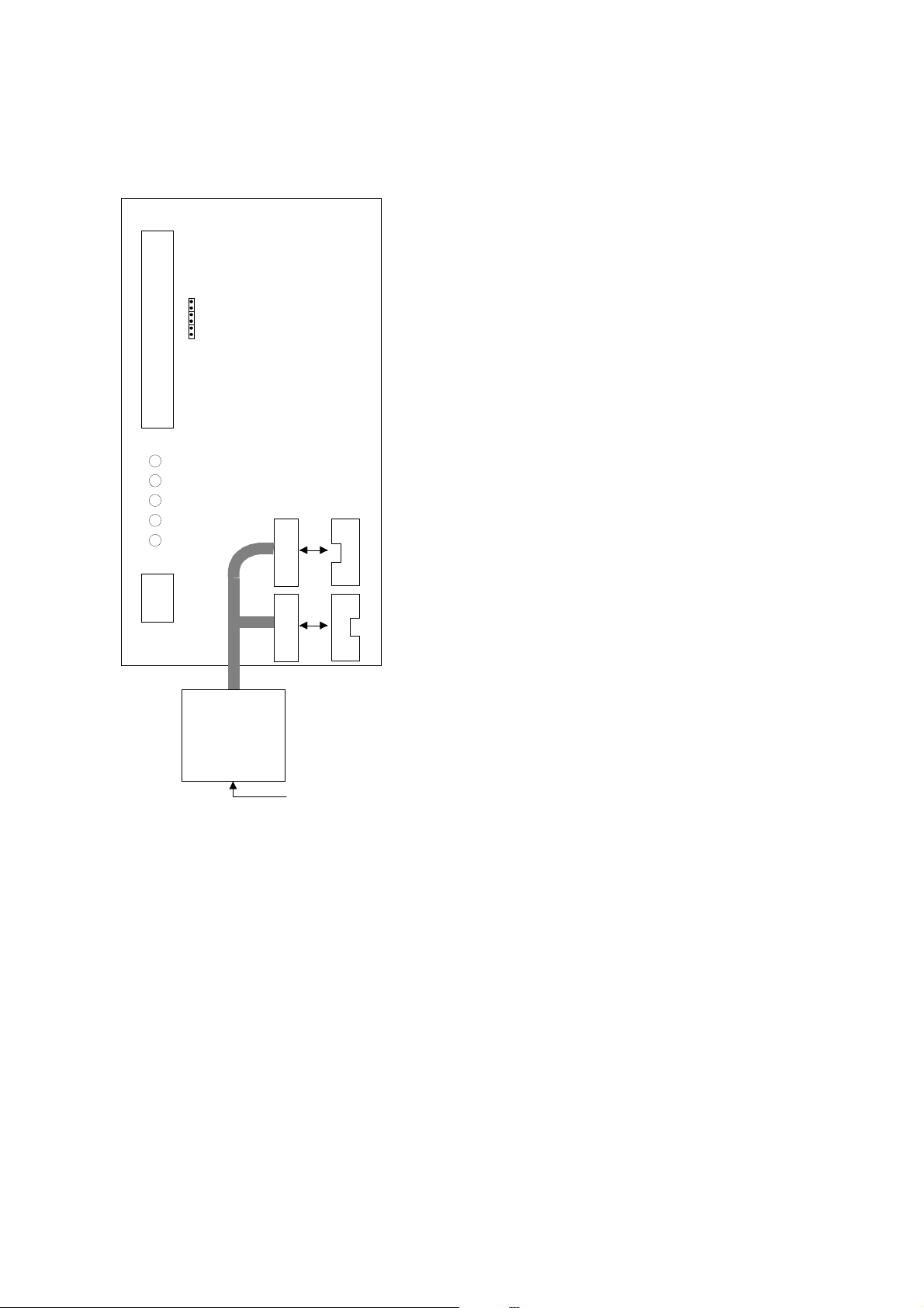
5.3 /O-control connections
Terminal Signal Description
301 DID1 External fault
(closing contact)
Contact open = no fault
Contact closed = fault
302 DID2 Run disable Contact open = start of motor enabled
Contact closed = start of motor disabled
303 DID3 Acceler. / Decel. time
selection
Contact open = time 1 selected
Contact closed = time 2 selected
304 DID4 Jogging speed selection Contact open = no action
Contact closed = jogging speed
305 COMD Common for DID1-DID2 Connect to GND or +24 V
306 +24 V Control voltage output Voltage for switches, etc. max. 0.1 A
307 COME Common for DIE3-DIE4 Connect to GND or +24 V
308 GND I/O ground Ground for reference and controls
309 DID5A+ Pulse input A
310 DID5A- (differential input)
Encoder
311 DID6B+ Pulse input B 90 degrees phase shift compared
312 DID6B- (differential input) to pulse input A
313 DID7Z+ Pulse input Z one pulse per one revolution
314 DID7Z- (differential input)
315 GND I/O ground Ground for reference and controls
316 DOD1 Open collector output 1 READY
317 DOD2 Open collector output 2 RUN
318 DOD3 Open collector output 3 FAULT
319 DOD4 Open collector output 4 FIELDBUS CONTROL
320 GND I/O ground Ground for reference and controls
Signal from
motor termistor
327 TI+ Termistor input
328 TI-
Figure 2. Control connections
_________________________________________________________________________________________
Vacon Plc Phone +358-201 2121 Fax: +358-201 212 205
Page 12

VACON CX Interbus-S user’s manual
_________________________________________________________________________________________
Page
12
6. COMMISSIONING
Check first commissioning of the frequency converter from User's manual CX/CXL frequency converter
(Chapter 8.)
Commissioning of the Fieldbus board:
1. Check that Multi-purpose Control Application II (or e.g. Fieldbus Application) is selected.
(Parameter P0.1 = 0)
2. Initial connection between Master - Drive using PCP-service, Initial.
3. Wait until Initial confirmation is received.
Start-up test:
DRIVE APPLICATION
1. Check that the active control place is I/O terminals (not control panel)
2. Set parameter “Fieldbus control select” to value 1(On).
MASTER SOFTWARE
1. ProcessDataInput 1 is now value xx60hex, SWITCH ON DISABLED
(if ProcessDataInput 1 = xx40hex)
- Parameters can be read and write
2. Write to ProcessDataOutput 1 value xxx6hex.
3. Wait until status ProcessDataInput 1 value is xx21hex, READY TO SWITCH ON
4. Write to ProcessDataOutput 1 value xxx7hex.
5. Wait until status ProcessDataInput 1 value is xx23hex, SWITCHED ON
6. Write to ProcessDataOutput 1 value xxxFhex.
7. Wait until status ProcessDataInput 1 value is xx27hex, OPERATION ENABLE
- Drive control is now enable (Run State = ON)
8. Set Nominal Speed Value using variable ProcessDataOutput 2 variable.
Read Actual Speed using variable ProcessDataInput 2.
If ProcessDataInput 1 = xx08hex or xx28hex Device status is MALFUNCTION
_________________________________________________________________________________________
Vacon Plc Phone +358-201 2121 Fax: +358-201 212 205
Page 13

VACON CX Interbus-S user’s manual
Page
13
_________________________________________________________________________________________
7. DRIVECOM
The DRIVECOM user group is standardizing the most important functions and parameters of the drive:
• Device control state machine
• Profile parameters
• PCP-communication services
7.1 Device control State machine
The state machine describes the device status and the possible control sequence of the drive. The state
transitions can be generated by using “control word” parameter. The “status word” parameter indicates
the current status of state machine. The modes INIT, STOP, RUN and FAULT (see figure 7-1)
correspond to the actual mode of the Drive.
SWITCHED ON (=xx23 hex) is one value of the “status word”.
Shutdown (=xxxx x110 bin) is one value of the “control word”.
Fault
Power on
MALFUNCTION REACTION ACTIVE
FAULT
xxxFh or xx2Fh
Disable voltage
xxxx xx0x
Shutdown
xxxx x110
NOT READY TO SWITCH ON
INIT
xx00h
Automatic
SWITCH ON DISABLED
xx40h or xx60h
STOP
Shutdown
xxxx x110
READY TO SWITCH ON
xx21h
STOP
Switch on
xxxx x111
SWITCHED ON
STOP
xx23h
Disable voltage
xxxx xx0x
Quick stop
xxxx x01x
Shutdown
xxxx x110
MALFUNCTION
FAULT
Disable voltage
xxxx xx0x
Quick stop
xxxx x01x
xx08h or xx28h
AutomaticAutomatic
Reset malfunction
0xxx xxxx
1xxx xxxx
Disable voltage
xxxx xx0x
Enable operation
xxxx 1111
OPERATION ENABLED
RUN
Disable operation
xxxx 0111
xx27h
Quick stop
xxxx x01x
QUICK STOP ACTIVE
STOP
xx07h
Figure 1. States of the device control
_________________________________________________________________________________________
Vacon Plc Phone +358-201 2121 Fax: +358-201 212 205
Page 14

VACON CX Interbus-S user’s manual
_________________________________________________________________________________________
STATE STATUS OF THE DRIVE
Page
14
NOT READY TO SWITCH ON
-The interface board initialization is running.
-The drive function is disabled.
SWITCH ON DISABLED
-Initialization was completed.
-The parameters can read and write.
-The drive function is disabled.
READY TO SWITCH ON
-The parameters can read and write.
-The drive function is disabled.
SWITCHED ON
-The parameters can read and write.
-The drive function is disabled.
OPERATION ENABLED
-The parameters can read and write.
-The drive function is enabled.
INIT
STOP
STOP
STOP
RUN
MALFUNCTION REACTION ACTIVE
-The drive function is disabled.
-The fault trip occur
MALFUNCTION
-The drive function is disabled.
-The drive is fault state.
-The interface board waits for falling edge of reset malfunction bit.
QUICK STOP ACTIVE
-The parameters can read and write.
-The drive function is enabled.
Table 1. Descriptions of the states
FAULT
FAULT
STOP
_________________________________________________________________________________________
Vacon Plc Phone +358-201 2121 Fax: +358-201 212 205
Page 15

VACON CX Interbus-S user’s manual
Page
15
_________________________________________________________________________________________
7.2 Profile Parameters
Index Name Type Object Data Access
hex dec
length rights
6000 24576 Process Input Data Description PDD-structure Record 13 R
6001 24577 Process Output Data Description PDD-structure Record 13 R
6002 24578 Process Output Data Enable Boolean Var 1 R/W
6007 24583 Connection Abort Option Code Interger 16 Var 2 R/W
603F 24639 Malfunction Code Octet String Var 2 R
6040 24640 Control Word Octet String Var 2 R/W
6041 24641 Status Word Octet String Var 2 R
6042 24642 Nominal Speed Var 2 R/W
6043 24643 Speed Reference Variable Interger 16 Var 2 R
6044 24644 Actual Speed Interger 16 Var 2 R
6046 24646 Speed Min Max Amount Unsigned 32 Array 8 R/W
6048 24648 Speed Acceleration Ramp Record 6 R/W
6049 24649 Speed Deceleration Ramp Record 6 R/W
604B 24651 Face Value Factor Integer 16 Array 4 R/W
Table 2. List of the profile parameters
Type Value range
Boolean FALSE = 00hex
, TRUE = FFhex
Octet String 8 bit / byte binary coded
Integer 8 -128 ... 127
Unsigned 8 0 ... 255
Interger 16 -32768 ... 32767
Unsigned 16 0 ... 65535
Integer 32 -2147483648 ... 2147483647
Unsigned 32 0 ... 4294967295
PDD-structure Subindex 1: Process data length Unsigned 8
Subindex 2: 1-index process input/output data Unsigned 16
Subindex 3: 1-subindex process input/output data Unsigned 8
Subindex 4: 2-index process input/output data Unsigned 16
Subindex 5: 2-subindex process input/output data Unsigned 8
Ramp Subindex 1: Delta speed Unsigned 32
Subindex 2: Delta time Unsigned 16
R Read only
WWrite
_________________________________________________________________________________________
Vacon Plc Phone +358-201 2121 Fax: +358-201 212 205
Page 16

VACON CX Interbus-S user’s manual
_________________________________________________________________________________________
7.2.1 Process Input Data Description (6000HEX)
This parameter contains the data defining which process input data is mapped to which communication
objects. Input data is data from the drive to the master.
Object description
Index 6000 hex
Object code Record
Data type PDD structure
Access rights Read-all
Value description
Subindex 1 Process data length
Value range Unsigned 8
Default value 4
Subindex 2 1-index process input data
Value range Unsigned 16
Default value 6041 hex
Subindex 3 1-subindex process input data
Value range Unsigned 8
Default value 00 hex
Subindex 4 2-index process input data
Value range Unsigned 16
Default value 6044 hex
Subindex 5 2-subindex process input data
Value range Unsigned 8
Default value 00 hex
Page
16
7.2.2 Process Output Data Description (6001HEX)
This parameter contains the data defining which process output data is mapped to which
communication objects. Output data is data from the master to the drive.
Object description
Index 6001 hex
Object code Record
Data type PDD structure
Access rights Read-all
Value description
Subindex 1 Process data length
Value range Unsigned 8
Default value 4
Subindex 2 1-index process output data
Value range Unsigned 16
Default value 6040 hex
Subindex 3 1-subindex process output data
Value range Unsigned 8
Default value 00 hex
Subindex 4 2-index process output data
Value range Unsigned 16
Default value 6042 hex
Subindex 5 2-subindex process input data
Value range Unsigned 8
Default value 00 hex
_________________________________________________________________________________________
Vacon Plc Phone +358-201 2121 Fax: +358-201 212 205
Page 17

VACON CX Interbus-S user’s manual
_________________________________________________________________________________________
7.2.3 Process Output Data Enable (6002HEX)
This parameter enables/disables the process data channel.
Object description
Index 6002 hex
Object code Simple variable
Data type Boolean
Length 1 byte
Access rights Read-all, Write-all
Value description
Value range TRUE, FALSE
Default value TRUE
7.2.4 Connection Abort Option Code (6007HEX)
The parameter “Connection Abort Option Code” defines which function is executed when connection is
aborted.
Page
17
Object description
Index 6007 hex
Object code Simple variable
Data type Integer 16
Length 2 bytes
Access rights Read-all, Write-all
Value description
Value range Integer 16
Default value 0
Abort values:
Value Description
-32768 ... -1 No action
0 No action
1 Malfunction
2 “Voltage Disabled” device control command
3 “Quick Stop” device control command
4 ... 32767 No action
_________________________________________________________________________________________
Vacon Plc Phone +358-201 2121 Fax: +358-201 212 205
Page 18

VACON CX Interbus-S user’s manual
_________________________________________________________________________________________
7.2.5 Malfunction code (603Fhex)
When a fault trip occurs, device status is Malfunction and parameter “Malfunction code” indicates the
current fault code.
Object description
Index 603F hex
Object code Simple variable
Data type Octet string
Length 2 bytes
Access rights Read-all
Value description
Value range Unsigned 16
Default value 0
Malfunction codes:
Page
18
VACON Fault Code DRIVECOM
fault Code
1 Overcurrent 2300 General overcurrent
2 Overvoltage 3210 Overvoltage inside the device
3 Earth Fault 2330 Short to earth
4 Inverter Fault 5420 Gate drivers or IGBT bridge
5 Charging Switch 5120 DC link power supply
9 Under Voltage 3220 Undervoltage inside the device
10 Input Phase Supervision 3130 Phase failure
11 Output Phase Supervision 3130 Phase failure
12 Brake Chopper Supervision 7111 Brake chopper failure
13 Vacon Under Temperature 4210 Excess device temperature
14 Vacon Over Temperature 4220 Inadequete device temperature
15 Motor Stalled 7120 Motor
16 Motor Over Temperature 7120 Motor
17 Motor Underload 7120 Motor
18 Analog Input HW fault 5200 Control
19 OptionBoard Identification 7000 Additional modules
20 10 V Voltage Reference 5110 Low voltage power supply
21 24 V Supply 5112 +24 V power supply
22 EEPROM Checksum Fault 7600 Data memory
23 EEPROM Checksum Fault 7600 Data memory
24 EEPROM Checksum Fault 7600 Data memory
25 Microprocessor Watch Dog 6010 Software reset (Watchdog)
26 Panel Communication Error 7510 Communication
27 Fieldbus Communication Error 7510 Communication
28 Application Change 6200 Internal software
29 Termistor Fault 7200 Measurement circuits(Additional modules)
36 Analog Input Iin<4mA 5200 Control
37 Ap Fault Code 37 6200 Internal software
38 Ap Fault Code 38 6200 Internal software
39 Ap Fault Code 39 6200 Internal software
40 Ap Fault Code 40 6200 Internal software
41 External Fault 9000 External malfunction
Meaning
hex
_________________________________________________________________________________________
Vacon Plc Phone +358-201 2121 Fax: +358-201 212 205
Page 19

VACON CX Interbus-S user’s manual
Page
19
_________________________________________________________________________________________
7.2.6 Control Word (6040hex)
The Control command for the state machine (see figure 7.1). The state machine describes the device
status and the possible control sequence of the drive.
Object description
Index 6040 hex
Object code Simple variable
Data type Octet string
Length 2 bytes
Access rights Read-all, Write-all
Value description
Value range Unsigned 16
Default value -
The control word is composed of 16 bits that have the following meanings:
Bit Name
0 Switch on
1 Disable voltage
2 Quick stop
3 Enable operation
4 Not used
5 Not used
6 Not used
7 Reset malfunction
8 Reserved
9 Reserved
10 Reserved
11 Special
12 Special
13 Special
14 Special
15 Special
(*
(*
(*
(*
(*
(*
See Appendix A
The device control commands are triggered by following bit combinations in the control word:
Command Bit 7
Reset
malfunction
Bit 3
Enable
Operation
Bit 2
Quick Stop
Bit 1
Disable
voltage
Bit 0
Switch on
Shutdown X X 1 1 0
Switch on XX111
Disable voltage X X X 0 X
Quick stop X X 0 1 X
Disable operation X 0111
Enable operation X 1111
Reset malfunction0>1XXXX
0>1: Change from bit=0 to bit=1
X: Bit is irrelevant
Status Word (6041hex)
Information about the status of the device and messages is indicated in the status word.
_________________________________________________________________________________________
Vacon Plc Phone +358-201 2121 Fax: +358-201 212 205
Page 20

VACON CX Interbus-S user’s manual
_________________________________________________________________________________________
Object description
Index 6041 hex
Object code Simple variable
Data type Octet string
Length 2 bytes
Access rights Read-all
Value description
Value range Unsigned 16
Default value -
The status word is composed of 16 bits that have the following meanings:
Bit Name
0 Ready to switch on
1 Switched on
2 Operation enabled
3 Malfunction
4 Voltage disabled
5 Quick stop
6 Switch on disabled
7 Warning active
8 Drive RUN/STOP
9 Remote
10 Face value reached
11 Limit value
12 Not used
13 Not used
14 Not used
15 Not used
Page
20
The device status is indicated by the following bit combinations in the status word:
State Bit 6
Switch on
disabled
Not ready to switch on 0 X 0 0 0 0
Switch on disabled 1 X 0 0 0 0
Ready to switch on 0 1 0 0 0 1
Switched on 0 1 0 0 1 1
Operation enabled 0 1 1 1 1 1
Malfunction 0 X 0 0 0 0
Malfunc reaction active 0 X 1 1 1 1
Quick stop active 0 0 0 0 0 1
X: Bit is irrelevant
Bit 5
Quick Stop
Bit 3
Malfunction
Bit 2
Operation
enabled
Bit 1
Switched on
Bit 0
Ready to
switch on
_________________________________________________________________________________________
Vacon Plc Phone +358-201 2121 Fax: +358-201 212 205
Page 21

VACON CX Interbus-S user’s manual
_________________________________________________________________________________________
7.2.7 Nominal Speed (6042hex)
Speed reference of the drive. The unit of the “Nominal Speed” is rpm. It is multiplied by the “Face Value
Factor”.
Object description
Index 6042 hex
Object code Simple variable
Data type Integer 16
Length 2 bytes
Access rights Read-all, Write-all
Value description
Value range Integer 16
Default value 0
7.2.8 Speed Reference Variable (6043hex)
Page
21
Speed reference after ramp function, scaled to same unit as the “Nominal speed” (rpm). It is multiplied
by the inverse of the “Face Value Factor”.
Object description
Index 6043 hex
Object code Simple variable
Data type Integer 16
Length 2 bytes
Access rights Read-all
Value description
Value range Integer 16
Default value 0
7.2.9 Actual Speed (6044hex)
Actual speed of the motor, scaled to same unit as the “Nominal speed value” (rpm). It is multiplied by the
inverse of the “Face Value Factor”.
Object description
Index 6044 hex
Object code Simple variable
Data type Integer 16
Length 2 bytes
Access rights Read-all
Value description
Value range Integer 16
Default value 0
_________________________________________________________________________________________
Vacon Plc Phone +358-201 2121 Fax: +358-201 212 205
Page 22

VACON CX Interbus-S user’s manual
Page
22
_________________________________________________________________________________________
7.2.10 Speed Min Max Amount (6046hex)
Defines speed limits of the drive in rpm. The parameter consist of a minimum and a maximum speed.
Object description
Index 6046 hex
Object code Array
Data type Octet string
Length 2 bytes
Access rights Read-all, Write-all
Value description
Subindex 1 Speed min amount
Value range Unsigned 32
Default value 0
Subindex 2 Speed max amount
Value range Unsigned 32
Default value 1500 rpm
7.2.11 Speed Acceleration (6048hex)
This parameter specifies the slope of the acceleration ramp. The parameter consist of two parts: the
delta speed and the delta time.
v / rpm
delta speed
delta time
Object description
Index 6048 hex
Object code Record
Number of elements 2 elements
Data type Ramp
Access rights Read-all, Write-all
Value description
Subindex 1 Delta speed
Value range Unsigned 32
Default value 1500 rpm
Subindex 2 Delta time
Value range Unsigned 16
Default value 3 s
t / sec
_________________________________________________________________________________________
Vacon Plc Phone +358-201 2121 Fax: +358-201 212 205
Page 23

VACON CX Interbus-S user’s manual
Page
23
_________________________________________________________________________________________
7.2.12 Speed Deceleration (6049hex)
This parameter specifies the slope of the deceleration ramp. The parameter consist of two parts: the
delta speed and the delta time.
v / rpm
delta speed
delta time
t / sec
Object description
Index 6049 hex
Object code Record
Number of elements 2 elements
Data type Ramp
Access rights Read-all, Write-all
Value description
Subindex 1 Delta speed
Value range Unsigned 32
Default value 1500 rpm
Subindex 2 Delta time
Value range Unsigned 16
Default value 3 s
_________________________________________________________________________________________
Vacon Plc Phone +358-201 2121 Fax: +358-201 212 205
Page 24

VACON CX Interbus-S user’s manual
_________________________________________________________________________________________
7.2.13 Face Value Factor (604Bhex)
The “Face Value Factor” serves to modify the resolution or directing range of the specified face value. It
is included in calculation of the specified face value and the output variables of the speed function only.
Numerator
Speed Reference = Nominal Speed * ------------------------
Denominator
Denominator
Actual Speed = Actual Speed * ------------------------
Numerator
Object description
Index 604B hex
Object code Array
Number of elements 2 elements
Data type Integer 16
Length 2 bytes
Access rights Read-all, Write-all
Page
24
Value description
Subindex 1 Numerator
Value range 1 ... 100
Default value 1
Subindex 2 Denominator
Value range 1 ... 100
Default value 1
_________________________________________________________________________________________
Vacon Plc Phone +358-201 2121 Fax: +358-201 212 205
Page 25

VACON CX Interbus-S user’s manual
_________________________________________________________________________________________
Page
25
8. VACON PARAMETERS
The Vacon variables and parameters can be read and write using following indexes:
Index Name Type Object Data Access
hex dec
5FFF 24575 Monitoring variable 1 Interger 16 Array 4 R/W
5FFE 24574 Monitoring variable 2 Interger 16 Array 4 R/W
5FFD 24573 Monitoring variable 3 Interger 16 Array 4 R/W
5FFC 24572 Parameter Write Interger 16 Array 6 R/W
5FFB 24571 Parameter Read Interger 16 Array 6 R/W
8.1 Monitoring variables
Monitored item is chosen by writing the number (nX) of monitored item to the wanted index (see Table
below). After this the chosen monitored item can be read from the wanted index. Separate monitored
items can be chosen to every index “channel” (5FFD ... 5FFF).
Length rights
Object description
Index 5FFF ... 5FFD hex
Object code Array
Number of elements 2 elements
Data type Integer 16
Length 2 bytes
Access rights Read-all, Write-all
Value description
Subindex 1 Number of monitored data
Value range Integer 16
Default value -
Subindex 2 Number of monitored data
Value range Integer 16
Default value -
Number Data name Step Unit Description
n1 Output frequency 0,01 Hz Frequency to the motor
n2 Motor speed 1 rpm Calculated motor speed
n3 Motor current 0,1 A Measured motor current
n4 Motor torque 1 % Calculated actual torque/nominal torque of the unit
n5 Motor power 1 % Calculated actual power/nominal power of the unit
n6 Motor voltage 1 V Calculated motor voltage
n7 DC-link voltage 1 V Measured DC-link voltage
n8 Temperature 1 °C Temperature of the heat sink
n9 Operating day counter DD.dd
n10 Operating hours, "trip
counter”
n11 MW-hours 0,001 MWh Total MW-hours, not resetable
n12 MW-hours, "trip counter" 0,001 MWh MW-hours, can be reset with programmable button
n13 Voltage/analogue input 0,01 V Voltage of the terminal Uin+ (control board)
n14 Current/analogue input 0,01 mA Current of terminals Iin+ and Iin- (control board)
_________________________________________________________________________________________
Vacon Plc Phone +358-201 2121 Fax: +358-201 212 205
HH.hh
Operating days 1), not resetable
Operating hours 2), can be reset with program-button
#3
#4
Page 26

VACON CX Interbus-S user’s manual
Page
26
_________________________________________________________________________________________
n15 Digital input status, gr. A 0 = Open Input, 1 = Closed Input (Active)
n16 Digital input status, gr. B 0 = Open Input, 1 = Closed Input (Active)
n17 Digital and relay output
0 = Open Input, 1 = Closed Input (Active)
status
n18 Control program Version number of the control software
n19 Unit nominal power 0,1 kW Shows the power size of the unit
n20 Motor temperature rise 1 % 100%= temperature of motor has risen to nominal
value
1)
DD = full days, dd = decimal part of a day
2)
HH = full hours, hh = decimal part of an hour
Table. Monitored Items
8.2 Parameter Write
By using index 5FFC can be written in to Vacon parameter. The group number of parameter, parameter
number and parameter value will be written in to index. Numbering of the parameter as well as
parameter ranges and steps can be found in the application manual in question. The parameter value
should be given without decimals.
Object description
Index 5FFC hex
Object code Array
Number of elements 3 elements
Data type Integer 16
Length 2 bytes
Access rights Read-all, Write-all
Value description
Subindex 1 Parameter group number
Value range Integer 16
Default value -
Subindex 2 Parameter number
Value range Integer 16
Default value -
Subindex 3 Parameter value
Value range Integer 16
Default value -
Example: Write value 25 to Vacon parameter 1.2
command WRITE
subindex 1 0001 hex
subindex 2 0002 hex
subindex 3 0019 hex
_________________________________________________________________________________________
Vacon Plc Phone +358-201 2121 Fax: +358-201 212 205
Page 27

VACON CX Interbus-S user’s manual
_________________________________________________________________________________________
8.3 Parameter read
Reading of the Vacon parameter is accomplished in two stages. At the first stage the read group
number of the parameter and parameter value is written in to 5FFB, parameter value is not important. At
the second stage the parameter value will be read from the same index, when the parameter value
without desimals is received.
Object description
Index 5FFB hex
Object code Array
Number of elements 3 elements
Data type Integer 16
Length 2 bytes
Access rights Read-all, Write-all
Value description
Subindex 1 Parameter group number
Value range Integer 16
Default value -
Subindex 2 Parameter number
Value range Integer 16
Default value -
Subindex 3 Parameter value
Value range Integer 16
Default value -
Page
27
_________________________________________________________________________________________
Vacon Plc Phone +358-201 2121 Fax: +358-201 212 205
Page 28

VACON CX Interbus-S user’s manual
_________________________________________________________________________________________
Page
28
9. PCP-COMMUNICATION SERVICES
Following services are supported:
• Initiate Establish connection
• Abort Abort connection
• Status Read drive status
• Identify Read manufacturer’s name, type and version
• Get OV Read the object description
• Read Read communication objects
• Write Write communication objects
9.1 Initiate
Establish a communication connection between master and slave. The drive controller returns the
following service parameters when answering the initiate service:
Access Protection Supported: TRUE
Version OV: 0001hex
Profile Number: 0021hex
Password: 00hex
9.2 Abort
Abort communication connection between two communication partners. The parameter “Connection
Abort Option Code” defines which function is executed when connection is aborted.
9.3 Status
Request device and user status from the drive. The drive controller returns the following values:
Logical status
0 Ready to communicate Remote
1 Limited number of services Local
Logical status Device status
Physical status
Physical status Status of the device control
0 Ready for operation OPERATION ENABLE
1 Partly ready for operation All other states
2 Not ready for operation Device not ready
3
Local Detail
= Status word (index 6041hex)
_________________________________________________________________________________________
Vacon Plc Phone +358-201 2121 Fax: +358-201 212 205
Page 29

VACON CX Interbus-S user’s manual
_________________________________________________________________________________________
9.4 Identify
Request identification data from the communication partner. The drive controller returns the following
values:
Page
29
Device manufacturer name:
Model Name:
Device version:
9.5 Get OV
Read object dictionary of the communication partner.
9.6 Read
This service is read out of the parameters. The result is parameter value if service was processed
successfully. The result is fault indication if service was not processed successfully. The fault
indications:
Error
Class
6 3 00 No access rights
6 5 00 Subindex is invalid
6 5 10 A service parameter has assumed an invalid value
6 6 00 The object is not a parameter
6 7 00 The object does not exist
8 0 00 Service cannot be executed
8 0 20 Service can currently not be executed
Error
Code
VACON
VACON IBS-BOARD
Revision 1.0
Additional
Code
Meaning
9.7 Write
This service is read out of the parameters. The result is acknowledgment if service was processed
successfully. The result is fault indication if service was not processed successfully. The fault
indications:
Error
Class
6 3 00 No access rights
6 5 00 Subindex is invalid
6 5 10 A service parameter has assumed an invalid value
6 6 00 The object is not a parameter
6 7 00 No object exists under this index
6 8 00 The data does not correspond to the data type of the object
8 0 00 Service cannot be executed
8 0 20 Service can currently not be executed
8 0 21 Cannot be executed because of local control
_________________________________________________________________________________________
Vacon Plc Phone +358-201 2121 Fax: +358-201 212 205
Error
Code
Additional
Code
Meaning
Page 30

VACON CX Interbus-S user’s manual
_________________________________________________________________________________________
Page
30
10. Extra information
More information about Interbus-S system, Host Systems and DriveCom profile:
INTERBUS-S CLUB
Phone +49-631/79424
Fax +49-631/97658
Deutschland
_________________________________________________________________________________________
Vacon Plc Phone +358-201 2121 Fax: +358-201 212 205
Page 31

APPENDIX A
Special Actual Values
Default value of Index 6044hex (Process channel 1) is Actual Speed (RPM).
The user can also read the frequency converter’s actual values via a Process Channel 1. Meaning of
Process channel 1 can be selected by setting a Control Word (6040hex) bits 15...11. The user can
select to show one of the monitoring page variables or active fault code.
Control Word (bit 15...11) is binary code as follows:
Control Word Description
bit 15 bit 14 bit 13 bit 12 bit 11
0 0 0 0 0 Default, Actual Speed (RPM)
0 0 0 0 1 n1 (see table 8-1)
0 0 0 1 0 n2 (see table 8-1)
0 0 0 1 1 n3 (see table 8-1)
1 1 1 0 1 n29 (see table 8-1)
1 1 1 1 0 Active Fault Code
1 1 1 1 1 Actual Speed (RPM)
.
.
Process data channels
Nominal Speed
Actual Value Speed
Process channel 1 Process channel 2
Control Word
Status Word
DRIVE
Page 32

Vacon Plc
P.O. Box 25
Runsorintie 7
FIN-65381 VAASA
Finland
Phone: +358-201 2121
Fax: +358-201 212 205
UD00105G
 Loading...