

Page 1

ENGINEERING TOMORROW
Functional Safety Application Guide
Encoder-less Safety Functions SLS, SSR using DOLD Frequency
Monitor
VACON® and VLT® FC-series
vlt-drives.danfoss.com
Page 2

Page 3
Contents Functional Safety Application Guide
Contents
1 Introduction
1.1 Purpose
1.2 Scope
1.3 Abbreviations
2 Safety Functions SLS and SSR
3 SLS and SSR Implementation
3.1 Circuit Diagram
3.2 Safety Function Operation and Timing
3.2.1 Initial Conditions 11
3.2.2 Fault Handling 11
3.2.3 SLS Operation 11
3.2.4 SSR operation 11
3.3 Parameters and Conguration
4 Ordering Data for DOLD Components
4.1 Frequency Monitor
2
2
2
2
3
4
5
11
13
16
16
5 Functional Safety-related Data
5.1 SIL Calculation
Index
17
17
18
MN91A102 Danfoss A/S © 04/2017 All rights reserved. 1
Page 4
Introduction Encoder-less Safety Functions SLS, SSR using DOLD Frequency Monitor
11
1 Introduction
1.1 Purpose
This manual describes how to implement the safety
functions Safely Limited Speed (SLS) or Safe Speed Range
(SSR) using DOLD UH 6937 frequency monitor without
encoder.
The DOLD module can be used with the following
products:
VLT® HVAC Drive FC 102
•
VLT® Refrigeration Drive FC 103
•
VLT® AQUA Drive FC 202
•
VLT® Midi Drive FC 280
•
VLT® AutomationDrive FC 301
•
VLT® AutomationDrive FC 302
•
VACON® 100 Industrial
•
VACON® 100 Flow
•
VACON® NXP Liquid Cooled
•
VACON® NXP System Drive
•
VACON® NXP Air Cooled
•
VACON® NXP Common DC Bus
•
VACON® NXP Liquid Cooled Enclosed Drive
•
VACON® NXP Liquid Cooled Common DC Bus
•
Scope
1.2
This manual is intended for application designers, for
realizing safe speed functions of frequency converters
without encoder feedback, using an external frequency
monitor.
Abbreviations
1.3
PL Performance Level
SIL Safety Integrity Level
SLS Safely Limited Speed
SSR Safe Speed Range
STO Safe Torque O
Table 1.1 List of Abbreviations
2 Danfoss A/S © 04/2017 All rights reserved. MN91A102
Page 5
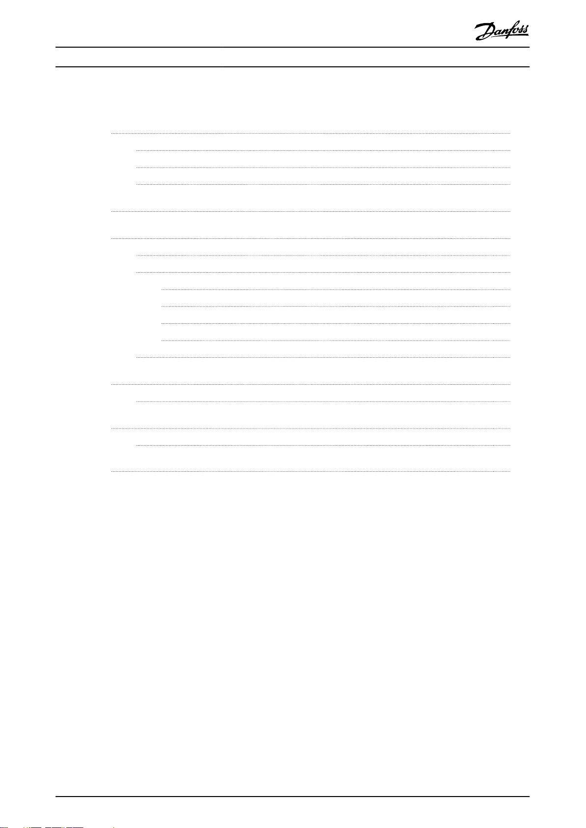
SLS limit
Speed
Time
130BF781.10
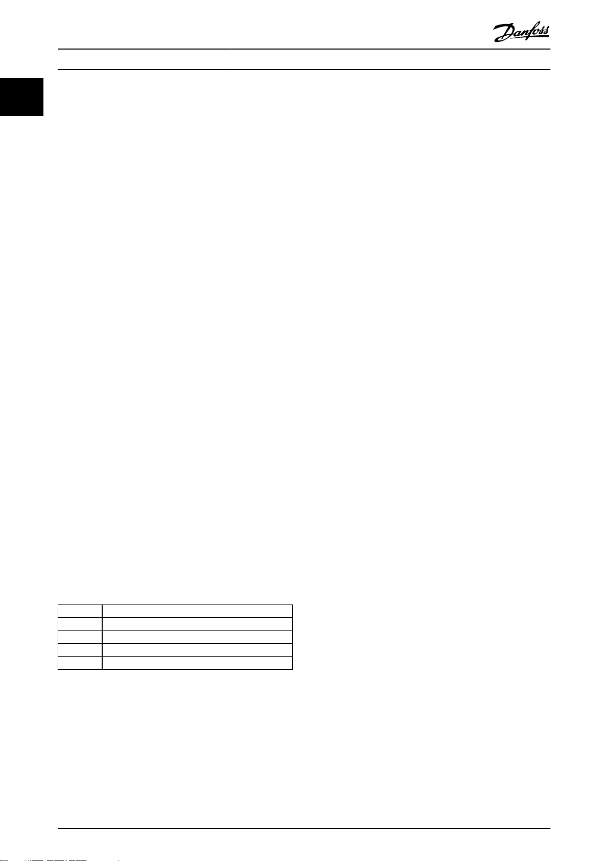
SSR upper limit
SSR lower limit
Speed
Time
130BF782.10
Safety Functions SLS and SS... Functional Safety Application Guide
2 Safety Functions SLS and SSR
The Safely Limited Speed (SLS) function monitors the
speed to a set limit value without any encoder feedback,
see Illustration 2.1. The frequency of the motor is measured
and compared to the limit value. If the measured value is
more than the set value, then the safety output relay is
deactivated to trigger the STO function.
Illustration 2.1 SLS Function
The Safe Speed Range (SSR) function monitors the speed
within a given range or outside a given range. See
Illustration 2.2.
Monitoring within the given range:
If the frequency is within the given speed range, the STO
signal is not active. If the measured frequency is outside
the given speed range, the relay output triggers the STO
function of the frequency converter.
Monitoring outside the given range:
If the frequency is outside the dened speed range, the
STO signal is not active. If the measured frequency lies
inside the limits, the relay output triggers the STO function
of the frequency converter.
In the standard module variant 0, 1 of the following
monitoring functions is selected:
Over frequency
•
Under frequency
•
Inside range
•
Outside range
•
The variant 1 module has extra selection inputs for
selecting 4 frequency modes during the operation.
NOTICE
If the frequency converter does not have an integrated
STO function, the relay outputs can be used to activate
the motor contactors to cut o the power to the motor.
2 2
Illustration 2.2 SSR Function
MN91A102 Danfoss A/S © 04/2017 All rights reserved. 3
Page 6
SLS and SSR Implementation Encoder-less Safety Functions SLS, SSR using DOLD Frequency Monitor
3 SLS and SSR Implementation
The SLS safety function implementation is based on the
STO function and the following safety-related components:
Frequency monitor (3rd party DOLD UH 6937)
33
•
The UH 6937 frequency module does not have
safe inputs to activate and deactivate the safety
functions. In variant 0, the module always
monitors the frequency. The monitoring can only
be muted by selecting the parameter in the
display. In variant 1, there are 4 digital safe inputs
available to select dierent frequency modes, and
1 of the combinations is the muting function.
Noise suppression
•
party DOLD LG 5130), optional
These lters are only required if there is
measurement errors after complete installation.
Third-party functional safety system or fail-safe
•
PLC (≤ SIL2), optional
A fail-safe PLC is required to implement the safety
logic based on the status of the relay outputs of
a frequency module. One of the use cases is, that
the relay output status is ignored as long as the
safety door is locked for SLS speed. Once the
door is opened, the safety relay output is used to
activate the STO of the frequency converter for
speed limit violations.
The circuit example in chapter 3.1 Circuit Diagram shows
the DOLD UH 6937 used with a Danfoss frequency
converter FC-series or VACON® series.
The auxiliary voltage 24 V is connected to terminals A1–A2.
Any 24 V PELV or SELV supply can be used. If no additional
devices are supplied via terminal 12 or 13 (+24 V), A1 can
be connected to terminal 12 or 13. A2 can be connected
to terminal 20 (0 V).
lter for measuring relays (3
NOTICE
Separate wires in separate cables with spacing in
between have to be used for each of the frequency
inputs. When monitoring 3-phase AC voltages, these
terminals have to be wired directly to the motor
connection terminals.
WARNING
RISK OF DEATH AND SERIOUS INJURY
If external forces act on the motor, for example in case
rd
of vertical axis (suspended loads) the motor must be
equipped with extra measures for fall protection. For
example, install extra mechanical brakes.
The noise lter (LG 5130) has 4 inductances connected in
series in each path for the 3 phases (input L1/L2/L3). This
provides broad band ltering up to high frequencies. If the
PE is connected, a Y-capacitor connected to PE is activated
and provides increased ltering (T-lter).
The noise lter is connected via its input terminals
L1/L2/L3 to the frequency converter output and the
frequency monitor device to the lter outputs L1’/L2’/L3’.
By connecting the noise lter between the frequency
converter and the measuring frequency monitor device,
the current owing via the coupling capacitances is
reduced. The reduction happens because the lter
elements create a rising impedance with a rising
frequency. This prevents disturbance or damage on the
connected device. Protection as shown in Illustration 3.5.
It is not mandatory to connect the PE to the frequency
monitor device terminals, but it increases the lter eect.
Terminals E1a, E1b, E2L, E2H, E3L, and E3H form the
measuring input. For low voltages (AC 8–280 V), the
measuring voltage is connected to E1a–E2L and E1b–E3L.
For higher voltages (AC 16–600 V ), the measuring voltage
is connected to E1a–E2H and E1b–E3H.
When monitoring single-phase AC voltage, the terminals
E1a–E2L or E1a–E2H should be connected directly to the
frequency converter. The terminals E1b–E3L or E1b–E3H
should be connected directly to the motor connection
terminals.
4 Danfoss A/S © 04/2017 All rights reserved. MN91A102
Chapter 3.2 Safety Function Operation and Timing includes
the SLS operation and timing.
Page 7
Remove the jumper wire between control
terminals 12, 37, 38 in the frequency converter.
-SF8
RESET
+FIELD
+FIELD
Ensure that the STO cables are shielded if they
are longer than 20 m (65.6 ft) or outside the cabinet.
-TA1
VLT FC 280
Frequency
converter
PE/GND
PE/GND
PE/GND
PE/GND
PE/GND
GND
PE/GND
L1 L2 L3
F
-FC1
_
95(PE)
91(L1)
92(L2)
93(L3)98(W)
97(V)
96(U)
99(PE)
12
37
38
55
U
-U2
V
W
U
NSGAFÖU 1.8/3 kV
BK
min. 2.5 mm
2
(14 AWG)
-WD1
-MA1
M
3~
BN BK GY
U1 V1 W1
E1a
E2L
E2H
E1b
E3L
E3H
13
13
14
14 23 24 A1+ A2 RES T1 T2 RF
4838
UH6937
E
-FC31
1
2
24 V DC 0 V DC
1
2 4 6
3 5
SH
130BF784.10
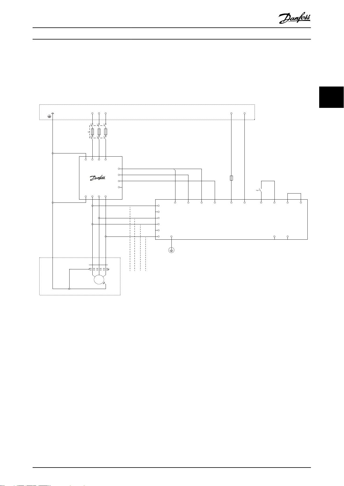
SLS and SSR Implementation Functional Safety Application Guide
3.1 Circuit Diagram
Illustration 3.1 shows the UH 6937 Circuit diagram. The relay contacts 13–14 and 23–24 can be used as STO input to the
frequency converter.
3 3
Illustration 3.1 FC 280 and UH 6937 Wiring Diagram
MN91A102 Danfoss A/S © 04/2017 All rights reserved. 5
Page 8

SD2-
+FIELD
L1 L2 L3
12345
6
-FC1
PE/GND
-TA1
NX Series
Frequency
Converter
L1 L2 L3
U V WPE/GND
U
V
U
PE/GND
-MA1
-WD1
PE/GND
PE/GND
3~
M
SH
U1BNW1V1
BK
GY
-
U2
E1a
E2L
E2H
E1b
E3L
E3H
GND
14 24
13 23 A1+ A2 RES T1 T2 RF
38 48
PE/GND
-WGB1
SH
PE/GND
1 432
2
SD1-
1
SD1+
23
RO1 NO
22
RO1 C
21
RO1 NC
43
SD2+
25
RO2 C26RO2 NO
29
TI1-
28
TI1+
-AG2
OPTAF
IFS+2XRO+PTC
SLOT B
X10
ON
X12
UNCUT
Thermistor
short circuit
supervision
1
2
-FC31
1
2
-FC32
1
2
-FC33
13
14
-SF8
RESET
24 V DC 0 V DC
UH6937
+FIELD
130BF789.10
NSGAFÖU 1.8/3 kV
BK
min. 2.5 mm
2
(14 AWG)
W
SLS and SSR Implementation Encoder-less Safety Functions SLS, SSR using DOLD Frequency Monitor
33
Illustration 3.2 NX Drive, OPT-AF, and UH 6937 Wiring Diagram
6 Danfoss A/S © 04/2017 All rights reserved. MN91A102
Page 9

RES
Use short-circuit protected cable
(if not inside an IP54 installation cabinet)
Remove the jumper wire between
control terminals 37 and 12 or 13
in the frequency converter.
UH6937
12345
6
-FC1
91(L1)
92(L2)
93(L3)
96(U)
97(V)
98(W)
99(PE)
-TA1
VLT FC 302
frequency
converter
U1
PE/GND
-MA1
3~
M
PE/GND
-WD1
BN
SH
-U2
E1a
E2L
E2H
E1b
E3L
E3H
U
V
U
W
13
23 A1+ A2
1
2
-FC 31
T1
13
14
-SF8
RESET
T2 RF
38 48
GND
PE/GND
+FIELD
+FIELD
PE/GND
PE/GND
95(PE)
PE/GND
14 24
12 or 13
37
L1 L2 L3 24 V DC 0 V DC
GYBK
V1 W1
130BF790 .10
NSGAFÖU 1.8/3 kV
BK
min. 2.5 mm
² (14 AWG)
SLS and SSR Implementation Functional Safety Application Guide
3 3
Illustration 3.3 FC 302 and UH 6937 Wiring Diagram
MN91A102 Danfoss A/S © 04/2017 All rights reserved. 7
Page 10

+FIELD
L1 L2 L3
12345
6
-FC1
PE/GND
-TA1
VACON 100
frequency
converter
L1 L2 L3
U V WPE/GND
U
V
U
PE/GND
-MA1
-WD1
PE/GND
PE/GND
3~
M
SH
U1BNW1V1
BK GY
-
U2
E1a
E2L
E2H
E1b
E3L
E3H
GND
14 24
13 23 A1+ A2 RES T1 T2 RF
38 48
PE/GND
-WGB1
SH
PE/GND
1 432
1
2
-FC31
1
2
-FC32
1
2
-FC33
13
14
-SF8
RESET
24 V DC 0 V DC
UH6937
+FIELD
Supervision ON (default)
Short circuit supervision
Supervision OFF
X23
STO board not activated
STO board activation
X10
STO board activated (default)
-AB1
SLOT C, D, E
OPT-BJ
Contact
RO1
Thermistor Input
TI1
1
STO1+2STO1-3STO2+4STO2-
25CO26
NO
29
TI1-
28
TI1+
130BF791.10
NSGAFÖU 1.8/3 kV
BK
min. 2.5mm
2
(14 AWG)
SLS and SSR Implementation Encoder-less Safety Functions SLS, SSR using DOLD Frequency Monitor
33
Illustration 3.4 VACON® 100, OPT-BJ, and UH 6937 Wiring Diagram
8 Danfoss A/S © 04/2017 All rights reserved. MN91A102
Page 11

PE L1 L2 L3
Motor Protection
FU
L1
L2
L1
L3
L1’
L2’
L1’
L3’
E1a
E2H
E1b
E3H
UH6937
LG5130
LG5130
M
3~
130BF783.10
SLS and SSR Implementation Functional Safety Application Guide
Illustration 3.5 shows the LG 5130 Circuit Diagram with noise ltering between the 3 phases of the frequency converter and
the frequency monitor UH 6937.
3 3
Illustration 3.5 LG 5130 Circuit Diagram
MN91A102 Danfoss A/S © 04/2017 All rights reserved. 9
Page 12

14
13
24
23
K1
K2
14
13
24
23
K1
K2
A1
A2 GND
E2H E2aE2L
E3H E3L E1b
+
A1
A2 GND
E2H
E2aE2L
E3H
E3L E1b
+
14 23
T1RFRES
38GND
48
13
T2
24 14
23
T1 RFRES
38
GND
48
13
T2
24
A1+A
SW1 SW2 SW3 SW4
M10823_d M10823_d
UH6937 UH6937/__1
130BF788.10
SLS and SSR Implementation Encoder-less Safety Functions SLS, SSR using DOLD Frequency Monitor
33
Terminal designation Signal designation
A1+ 24 V DC
A2 0 V
E1a, E1b, E2L, E2H, E3L, E3H Frequency measuring inputs
GND Reference potential for semiconductor monitoring output and control outputs
13, 14, 23, 24 Forcibly guided NO contacts for release circuit
38, 48 Semiconductor-monitoring output
T1, T2 Control output
RES, RF, SW1, SW2, SW3, SW4 Control input
A+, A GND Analog output
Illustration 3.6 Terminals Description
10 Danfoss A/S © 04/2017 All rights reserved. MN91A102
Page 13

SLS and SSR Implementation Functional Safety Application Guide
3.2 Safety Function Operation and Timing
The safe speed monitoring has to be congured for the
speed limits in the frequency converters applications. The
customer is responsible for dening the speed limits on
the risk assessment. The commissioning test report is made
available for the nal assessment and for future references.
3.2.1 Initial Conditions
If the safe speed limit monitor is congured without the
start-up delay and the RF feedback circuit is closed, it is
active immediately after the power-on.
3.2.2 Fault Handling
When faults are detected on or in the device, they are
indicated with a message in the display. If the fault
requires a reset of the device, the alarm and the associated
diagnostic message has to be acknowledged rst. Press the
left key for approximately 3 s to initiate a reset of the
device.
NOTICE
If a system failure is detected again after restart, the
device must be replaced and sent back to the
manufacturer.
3.2.3 SLS Operation
Typically, the SLS safety function is used for safe speed
monitoring according to a dened speed limit. In this case,
the SLS function denes the speed limit where it is
considered safe for personal interaction with the machine.
As long as the frequency of the frequency converter is
within the dened limit, the STO function is not active.
When the output frequency goes beyond the limit value,
STO is immediately activated so the motor coasts and
comes to a standstill. This coasting time must be
considered before allowing the access to the dangerous
zone.
The safe output on the frequency monitor UH 6937 is
active and the output relays remain closed, as long as the
actual speed is lower than the safe speed limit parameter
(SLS limit).
If the actual speed exceeds the safe speed limit parameter
(SLS limit), speed output relays are opened, and the safe
output signal is removed.
If an internal fault occurs, the SLS safety function can be
congured for automatic reset. If the function is congured
for a manual reset, the RESET input should be provided for
normal operation after removing the limit violations.
The module UH 6937 always monitors the congured
frequency limits. The frequency module does not have its
own safe inputs, therefore a third-party functional safety
system, for example a fail-safe PLC system, is used. It
activates the safe function when a safe function is
demanded. This means that more safety logic can be
prepared based on the status of the frequency module
relays in the PLC. For example, the PLC logic controls the
access to the dangerous zone via its output signal (door
control). The SLS output (relays) is connected to the failsafe PLC’s safety input. The access is allowed as long as the
frequency is below the SLS limit. If the speed limit is
exceeded, the STO of the frequency converter is
immediately activated via the fail-safe PLC output to bring
the system to a safe state.
The input frequency is compared to the setting value. As
the device measures the cycle duration, the fastest
frequency measurement is possible. Should the overfrequency function be set, the output relay switches to the
alarm mode when the set response parameter value
exceeds the
Should the frequency decrease to a value below the
response parameter, minus the set hysteresis, the output
relay is activated after the expiry of the reset delay time
period(tF). It then returns to its preset allowed supervisory
state. The underfrequency function means that the output
relay switches to the alarm mode when the set response
parameter value drops below the set alarm-delay
function(tV) time period. When the frequency returns to
the range governed by the response parameter, plus the
set hysteresis, the output relay returns to the preset
allowed state after the expiry of the reset-delay time
period(tF).
dened value in the alarm-delay function (tV ).
3.2.4 SSR operation
The SSR function is used for speed monitoring within or
outside of a dened speed range.
In the internal window function mode, the output relay
switches to the alarm setting when the frequency exceeds
the preset allowed range of both the upper and lower
response parameters, minus and/or plus the preset
hysteresis values (upper response parameter minus and/or
the lower response parameter plus the relative hysteresis
values). The output relay again switches back to the preset
allowed range after the expiry of the reset-delay time
period (tF).
In the external window function mode, the monitoring
function acts inversely to the internal window function.
Should the manual reset function be activated, the output
relay remains in alarm mode when the frequency returns
to the preset allowed range. A reset of the saved
3 3
MN91A102 Danfoss A/S © 04/2017 All rights reserved. 11
Page 14

Threshold
Hysteresis
Overfrequency
Underfrequency
Alarm memory
Monitoring function
“Overfrequency”
Monitoring function
“Underfrequency”
Monitoring function
“Inside range”
U
U
H
(A1/A2)
}
Threshold
Hysteresis
}
130BF785.10
t
A
t
A
t
A
t
V
t
V
t
V
t
V
t
V
t
F
t
F
t
F
t
F
t
F
t
F
A
V F
t = Start-up delay, t = Alarm delay, t = Response delay
M11332
Output relay
K1/K2
n
SLS and SSR Implementation Encoder-less Safety Functions SLS, SSR using DOLD Frequency Monitor
parameter is possible when the reset input is activated or
the auxiliary voltage is shut down.
When a start-up delay time period (tA) is set, the set startup delay time period expires initially when the auxiliary
33
voltage of the equipment is switched on and the “RF”
feedback circuit is closed. The start-up delay time period
also expires after a reset of the manual reset mode. During
this time period, a frequency evaluation is disabled and
the output relays remain at the preset allowed setting. The
start-up delay function can, for example, override an alarm
message during the start-up stage of a generator or
electric motor. Should the feedback circuit not be closed
after a reset (in the manual reset mode), the equipment
goes into a safe error state.
The frequency monitoring operation is shown in
Illustration 3.7.
Illustration 3.7 Frequency Monitor Timing
12 Danfoss A/S © 04/2017 All rights reserved. MN91A102
Page 15

13 +23
14
24
38
K2
K1
ON K1/K2 ERR
UH6937
safemaster
DOLO
E
SD
actual frequency
100Hz
f
1
130BF786.10
t
2
4
3
SLS and SSR Implementation Functional Safety Application Guide
3.3 Parameters and Conguration
The equipment can be congured via the display and the
setting keys on the display. See Illustration 3.8.
To enter the parameterization-mode on the device,
follow these steps:
1. Press and hold the [OK] key.
2. Press the [Reset] key.
3. A display test follows and has to be
acknowledged using the [OK] key, when it was
successful.
4. It is now possible to change the parameterization.
Before the device adopts changed parameters,
they must be
reasons.
conrmed once more for safety
Follow the installation guide from the manufacturer for a
detailed description. Table 3.1 shows a default congu-
ration of the frequency monitor.
The safe speed limit parameter (SLS limit) is congured to
the upper limit parameter of frequency mode 1. The lower
limit is congured to 0.0 Hz.
3 3
1 OK
2
3
4 Reset
Illustration 3.8 Frequency Monitor Device Display
▲
▼
MN91A102 Danfoss A/S © 04/2017 All rights reserved. 13
Page 16

SLS and SSR Implementation Encoder-less Safety Functions SLS, SSR using DOLD Frequency Monitor
1. Parameterization
1.1 Monitoring function
Overfrequency X
Underfrequency –
Inside range –
33
2. Display settings
1.2 Limits
1.3 Hysteresis
1.4 Time Delay
1.5 Alarm memory
1.6 Muting function
2.1 Languages
2.2 Contrast
2.3 Backlight
2.4 Status indicator
Outside range –
Frequency mode 1
Upper limit 400.0 Hz
Lower limit 200.0 Hz
Frequency mode 2
Upper limit 400.0 Hz
Lower limit 200.0 Hz
Frequency mode 3
Upper limit 400.0 Hz
Lower limit 200.0 Hz
Frequency mode 4
Upper limit 400.0 Hz
Lower limit 200.0 Hz
5%
Start-up delay 0.0 s
Response Delay 0.0 s
Alarm delay 0.1 s
Changeover bridging 0.0 s
Alarm memory X
Automatic reset –
Activate –
Deactivate X
English X
Deutsch –
Francais –
50 %
OFF –
10 s X
1 min –
5 min –
Manual X
10 s –
1 min –
5 min –
14 Danfoss A/S © 04/2017 All rights reserved. MN91A102
Page 17

SLS and SSR Implementation Functional Safety Application Guide
3. Factory settings
Parameters
Display settings
Parameter + display settings
4. Change tracking
Activate
5. About UH 6937
Table 3.1 Frequency Monitor Conguration
3 3
MN91A102 Danfoss A/S © 04/2017 All rights reserved. 15
Page 18

UH 6937 .02
_
/ 0 DC 24 V
_ _ _
Nominal voltage
0 = Standard
1 = with dierent frequency mode
and analogue output
Max. response value
0 = 600 Hz
1 = 1000 Hz
Type o terminals
PS (plug-in screw)
pluggable terminal blocks,
with screw terminals
Contacts
Type
130BF787.10
Ordering Data for DOLD Comp... Encoder-less Safety Functions SLS, SSR using DOLD Frequency Monitor
4 Ordering Data for DOLD Components
4.1 Frequency Monitor
The ordering information for the DOLD frequency monitor
is shown in Illustration 4.1.
44
Description Type Order
number
Safe frequency
monitor
Noise suppression
1)
lter
Illustration 4.1 Ordering Example
UH6937.02PS
DC24V
LG5130 0065015 2
0066820 1
Pcs. /
Pkt.
1) Even though the UH6937 has enough EMC immunity for
normal conditions, the suppression lter for each channel of
measurement is needed only when the frequency monitor
module does not function correctly due to high EMC or high
frequency noise.
16 Danfoss A/S © 04/2017 All rights reserved. MN91A102
Page 19

Functional Safety-related D... Functional Safety Application Guide
5 Functional Safety-related Data
5.1 SIL Calculation
The SLS safety function consists of 3 subsystems:
Frequency converter
•
Frequency monitor
•
Functional safety system, such as fail-safe PLC
•
These have dierent safety-related data.
The values for the fail-safe PLC must be at least the shown
values in Table 5.3.
IEC 61508 SIL2
EN 62061 SILCL 2
EN/ISO 13849: 2006 PL d Category 3
EN 61800-5-2 SIL2
PFH
1x10
-10
/h
5 5
Table 5.1 Subsystem VLT® AutomationDrive FC 302
IEC 61508 SIL3
EN 62061 SILCL 3
EN/ISO 13849: 2006 PL e Category 4
PFH
Table 5.2 Subsystem Frequency Monitor
IEC 61508
EN 62061
EN/ISO 13849: 2006
EN 61800-5-2
PFH
Table 5.3 Subsystem Fail-safe PLC
IEC 61508 SIL2
EN 62061 SILCL 2
EN/ISO 13849: 2006 PL d Category 3
EN 61800-5-2 SIL2
PFH
Table 5.4 SLS Safety Function
≥SIL2
≥SILCL 2
≥PL d ≥Category 3
≥SIL2
<9.1x10⁻⁸/h
-10
4.43x10
< 1x10⁻⁷/h
/h
MN91A102 Danfoss A/S © 04/2017 All rights reserved. 17
Page 20

Index Encoder-less Safety Functions SLS, SSR using DOLD Frequency Monitor
Index
D
DIN EN/ISO 13849: 2006..................................................................... 17
DOLD LG 5130.......................................................................................... 4
DOLD UH 6937......................................................................................... 4
E
EN 61800-5-2.......................................................................................... 17
EN 62061.................................................................................................. 17
External window function................................................................. 11
F
Fail-safe PLC............................................................................................... 4
Fault handling........................................................................................ 11
Frequency monitor conguration.................................................. 13
I
IEC 61508................................................................................................. 17
Inside range.............................................................................................. 3
Internal window function.................................................................. 11
O
Outside range........................................................................................... 3
Overfrequency......................................................................................... 3
P
PFH............................................................................................................. 17
S
Safe Torque O......................................................................................... 3
SIL calculation........................................................................................ 17
SLS operation......................................................................................... 11
SSR operation......................................................................................... 11
STO............................................................................................................... 3
see also Safe Torque O
T
Terminal 12................................................................................................ 4
Terminal 13................................................................................................ 4
Terminal 20................................................................................................ 4
Terminal description.............................................................................. 5
Terminals E1a, E1b, E2L, E2H, E3L, E3H............................................ 4
U
Underfrequency...................................................................................... 3
18 Danfoss A/S © 04/2017 All rights reserved. MN91A102
Page 21

Index Functional Safety Application Guide
MN91A102 Danfoss A/S © 04/2017 All rights reserved. 19
Page 22

Danfoss can accept no responsibility for possible errors in catalogues, brochures and other printed material. Danfoss reserves the right to alter its products without notice. This also applies to
products already on order provided that such alterations can be made without subsequential changes being necessary in specications already agreed. All trademarks in this material are property
of the respective companies. Danfoss and the Danfoss logotype are trademarks of Danfoss A/S. All rights reserved.
Danfoss A/S
Ulsnaes 1
DK-6300 Graasten
vlt-drives.danfoss.com
130R0800 MN91A102 04/2017
*MN91A102*
 Loading...