

Page 1

vacon 500x
ac drives
users manual
Page 2

1 z vacon summary of vacon 500x
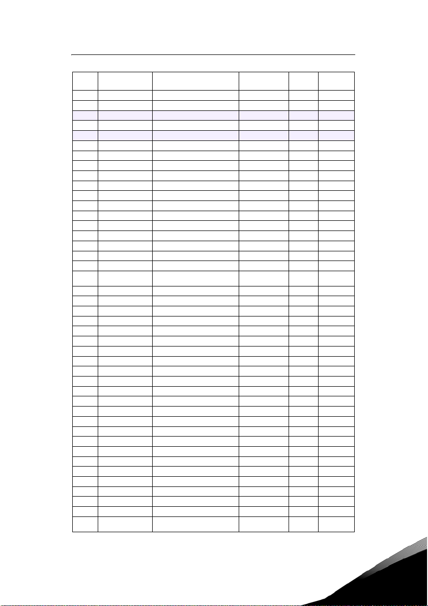
SUMMARY OF VACON 500X PARAMETERS
No. Parameter Name Options Default
001 Model Number Model dependent Read-only 61
002 Software Rev 0.00-99.99 Read-only 61
003 Rated Current 0.0-200.0 A Read-only 62
005 Serial No. 1 0-65535 Read-only 62
006 Serial No. 2 0-65535 Read-only 62
007 USB Soft. Rev 0.00 - 99.99 Read-only 62
008 Option Installed text string Read-only 62
009 Fbus Soft. Rev 0.00 - 99.99 Read-only 62
030 Pwr Down Date dd/mm/yy Read-only 62
031 Pwr Down Time Dd/hh/mm (Dd = Tu, Th, etc.) Read-only 62
102 Output Freq 0.0-400.0 Hz Read-only 62
103 Output Voltage 0-600 V Read-only 62
104 Output Current 0.0-200.0 A Read-only 62
105 Drive Load -200.0-200.0% Read-only 63
106 Load Torque -200.0-200.0% Read-only 63
107 Drive Temp -20.0-200.0 °C Read-only 63
108 Total Run Time 0.0-6553.5 h Read-only 63
109 Power On Hours 0-65535 h Read-only 63
110 Stator Freq 0.0-400.0 Hz Read-only 63
111 DC Bus Voltage 0 - 1000 Vdc Read-only 63
115 Drive Power Out 0.0-200.0% Read-only 63
116 Out Power (kW) 0.0 - 327.67 Read-only 63
117 MWh Meter 0 - 32767 Read-only 63
118 kWh Meter 0.0 - 999.9 Read-only 63
120 Today’s Date MM/dd/YY Read-only 63
121 Today’s Time hh:mm Read-only 63
Show Clock
Parameters
150
(Parameters 151-
179)
151 Tiime Zone Setup text string 12 (-5 East. US) 64
152 TOD Run Enable 0-23 hours, 0-59 min 12:00 64
154 TOD Run Disable 0-23 hours, 0-59 min 12:00 64
156 TOD Run En 2 0-23 hours, 0-59 min 12:00 64
158 TOD Run Dis 2 0-23 hours, 0-59 min 12:00 64
160 Weekend TOD En 0-23 hours, 0-59 min 12:00 64
162 Weekend TOD Dis 0-23 hours, 0-59 min 12:00 64
171 Reminder 1 Conf. text string 0 (disabled) 65
172 Reminder 1 Time 1-32000 hours 1 65
173 Reminder 1 ETA +/- 32000 hours Read-only 65
174 Reminder 2 Conf. text string 0 (disabled) 65
175 Reminder 2 Time 1-32000 hours 1 65
176 Reminder 2 ETA +/- 32000 hours Read-only 65
177 Reminder 3 Conf. text string 0 (disabled) 65
text string 0 (No) 64
User
Setting See Page
Tel. +358 (0)201 2121 • Fax +358 (0)201 212205
Page 3
summary of vacon 500x parameters vacon z 2
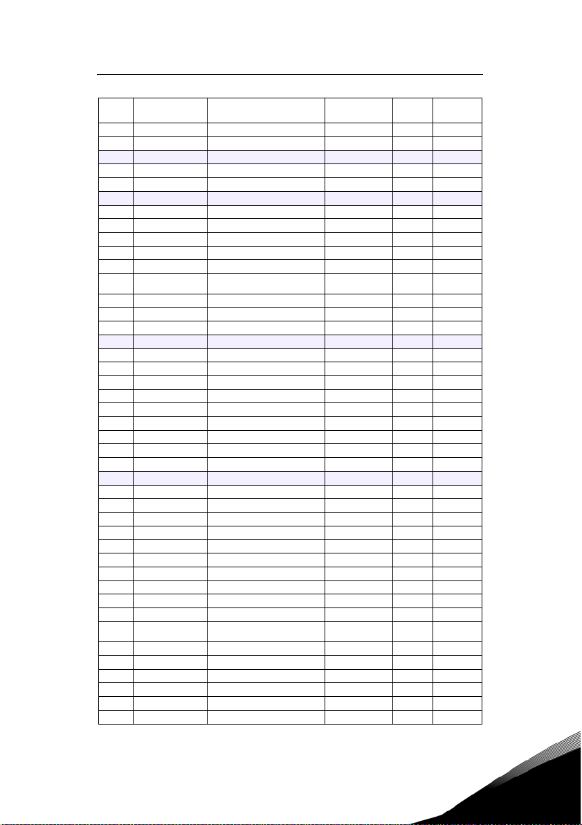
No. Parameter Name Options Default
178 Reminder 3 Time 1-32000 hours 1 65
179 Reminder 3 ETA +/- 32000 hours Read-only 65
201 Input Mode text string Local On ly 66
202 Rev Enable text string Forward 66
203 Stop Key Remote text string Coast 66
204 Ref Select text string Vin1 67
205 Vin1 Config text string 0-10V 67
206 Vin1 Offset 0.0% to 100.0% 0.00% 67
207 Vin1 Span 10.0% to 200.0% 100.00% 67
208 Cin Config text string 0-20mA 50 67
209 Cin Offset 0.0% to 100.0% 0.0% 68
210 Cin Span 10.0% to 200.0% 100.0% 68
211 Vin2 Config text string 0-10V 68
212 Vin2 Offset 0.0% to 100.0 % 0.00% 68
213 Vin2 Span 10.0% to 200.0% 100.00% 68
214 Vin1 Filter Time 0 to 1000 ms 20 ms 68
215 Cin Filter Time 0 to 1000 ms 20 ms 68
216 Vin2 Filter Time 0 to 1000 ms 20 ms 68
Trim Ref E nabl e
217
(Set k-Factor)
218 Trim % Factor -100.0 - 100.0% 0.0% 69
301 Min Frequency 0.0 - Max Freq. 0.0 Hz 69
302 Max Frequency 20.0 - 400.0 Hz 60.0 Hz 69
303 Preset Freq 1 Min Freq-Max Freq 5.0 Hz 69
304 Preset Freq 2 Min Freq-Max Freq 10.0 Hz 69
305 Preset Freq 3 Min Freq-Max Freq 20.0 Hz 69
306 Preset Freq 4 Min Freq-Max Freq 30.0 Hz 69
307 Preset Freq 5 Min Freq-Max Freq 40.0 Hz 69
308 Preset Freq 6 Min Freq-Max Freq 50.0 Hz 69
309 Cut-off Freq 0.0 - 5.0 Hz 0.0 Hz 70
310 Preset Freq 7 Min Freq-Max Freq 60.0 Hz 69
311 Preset Freq 8 Min Freq-Max Freq 0.0 Hz 69
312 Preset Freq 9 Min Freq-Max Freq 2.5 Hz 69
313 Preset Freq 10 Min Freq-Max Freq 7.5 Hz 69
314 Preset Freq 11 Min Freq-Max Freq 15.0 Hz 69
315 Preset Freq 12 Min Freq-Max Freq 25.0 Hz 69
316 Preset Freq 13 Min Freq-Max Freq 35.0 Hz 69
317 Preset Freq 14 Min Freq-Max Freq 45.0 Hz 69
318 Preset Freq 15 Min Freq-Max Freq 55.0 Hz 69
380 Keeper Input Cfg text string 4 (disabled) 70
381 Keeper Max Scale 0-32000 1000 70
382 Keeper Save Time 00:00 - 23:59 0:00 70
384 Keeper Save Rate text string 0 (24 hour) 70
Keeper Input
385
Valu e
text string 0 69
0-32000 Read-only 70
User
Setting See Page
24-hour support +358 (0)40 837 1150 • Email: vacon@vacon.com
Page 4

3 z vacon summary of vacon 500x
No. Parameter Name Options Default
386 Keeper Time Rate text string 1 (minute) 70
387 Keeper Rec. Num 0-255 Read-only 70
388 Active Kpr. Record 0-255 Read-only 71
389 Keeper Units text string 1 (GPM) 71
401 Ramp Select text string ART-DI 71
402 Accel Time 1 0.1-3200.0 sec 5.0 sec 71
403 Decel Time 1 0.1-3200.0 sec 5.0 sec 72
404 Accel Time 2 0.1-3200.0 sec 3.0 sec 72
405 Decel Time 2 0.1-3200.0 sec 3.0 sec 72
406 DC Inject Config text string DC at Stop 72
407 DC Inject Time 0.0-5.0 sec 0.2 sec 72
408 DC Inject Level 0.0% to 100.0% 50.0% 72
409 DC Inj Freq 0.0 to 20.0 Hz 0.0 Hz 72
410 DB Config text string Internal 73
414 S Ramp Rounding 1 - 100% 25% 73
415 Accel Time 3 0.1-3200.0 sec 10.0 sec 73
416 Decel Time 3 0.1-3200.0 sec 10.0 sec 74
417 Accel Time 4 0.1-3200.0 sec 15.0 sec 74
418 Decel Time 4 0.1-3200.0 sec 15.0 sec 74
490 App Macro text string Fac tory 74
491 Seq Appl text string Disabled 74
492 SIO Visible text string No 74
501 V/Hz Select text string Linear Fixed 75
502 Voltage Boost 0.0-50% 1.0% 75
503 V/Hz Knee Freq 25.0-400.0 Hz 60.0 Hz 75
504 Skip Freq Band 0.2-20.0 Hz 0.2 Hz 76
505 Skip Freq 1 Min Freq-Max Freq 0.0 Hz 76
506 Skip Freq 2 Min Freq-Max Freq 0.0 Hz 76
507 Skip Freq 3 Min Freq-Max Freq 0.0 Hz 76
508 Skip Freq 4 Min Freq-Max Freq 0.0 Hz 76
509 Rated Mtr Volt 100V-690V
510 Rated Mtr FLA 50% - 200% of ND Rating ND Rating 76
511 Rated Mtr RPM 0-24000 rpm 1750 rpm 76
512 Midpoint Freq 0.0 Hz-V/Hz Knee Freq 60.0 Hz 76
513 Midpoint Volt 0.0-100.0% 100.0% 76
514 Motor RS 0.0-655.35 Ohms
515 Power Factor 0.50-1.00 0.80 76
516 Slip Comp Enable text string No 77
517 Single Phase text string No 77
519 Find Mtr Data Not active / Motor RS Not active 77
520 Filter FStator 1 - 100 ms 8 ms 77
521 Start Field En text string No 77
522 Filter Time Slip 10 - 1000 ms 100 ms 77
Model
dependent
Model
dependent
User
Setting See Page
76
76
Tel. +358 (0)201 2121 • Fax +358 (0)201 212205
Page 5
summary of vacon 500x parameters vacon z 4
No. Parameter Name Options Default
523 Id Percent 0 - 200% Read-only 78
524 Iq Percent 0 - 200% Read-only 78
525 Power Fail Config text string CTS No Msg 78
526 UV Ride-Thru En text string w/ LVT 78
600 Current Lim Sel text string 0 79
601 Cur Lim Mtr Fwd 5%-150% 120% 79
602 Cur Lim Mtr Rev 5%-150% 120% 79
603 Cur Lim Reg Fwd 5%-150% 80% 79
604 Cur Lim Reg Rev 5%-150% 80% 79
605 Cur Lim Freq 0.0 - 400.0 Hz 3.0 Hz 79
606 Ramp Time CL 0.1-3200.0 sec 1.0 sec 79
Cur Limit
607
Minimum
608 Restart Number text string 0 80
609 Restart Delay 0-60 sec 60 sec 80
610 Timed OL Select text string 0 (Std Ind 60s) 80
613 Max Regen Ramp 100 - 1000% 300% 81
700 Vmet Config text string Freq Out 81
701 Vmet Span 0.0-200.0% 100.0% 81
702 Imet Config text string Drive Load 82
703 Imet Span 0.0-200.0% 100.0% 82
704 Imet Offset 0.0-90.0-% 0.0% 82
705 Relay 1 Select text string 1 (Drv Fault) 83
706 Relay 2 Select text string 2 (Drive Run) 83
707 DO1 Select text string 0 (Drv Ready) 83
708 DO2 Select text string 6 (At Speed) 83
720 Active Logic text string 1 (Active High) 83
721 DI1 Configure text string 0 (Preset 1) 84
722 DI2 Configure text string 1 (Preset 2) 84
723 DI3 Configure text string 2 (Preset 3) 84
724 DI4 Configure text string 6 (Alt Ramp) 84
725 DI5 Configure text string 7 (Fault Reset) 84
726 MOL Polarity text string 1 (NO Operate) 85
727 MOL Configure text string 21 (MOL) 84
740 Thres 1 Select text string 9 (Load High) 85
741 Thres 1 High -300.00 to 300.00% 100.00% 85
742 Thres 1 Low -300.00 to 300.00% 0.00% 85
743 Thres 2 Select text string
744 Thres 2 High -300.00 to 300.00% 100.00% 86
745 Thres 2 Low -300.00 to 300.00% 0.00% 86
746 Timer 1 Type text string 0 (On Delay) 86
747 Timer 1 Signal text string 1 (Drv Fault) 86
748 Timer 1 Time 0.0 - 320.0 sec 1.0 sec 86
749 Timer 2 Type text string 0 (On Delay) 86
0 - 50% 10% 79
15 (Current
High)
User
Setting See Page
85
24-hour support +358 (0)40 837 1150 • Email: vacon@vacon.com
Page 6

5 z vacon summary of vacon 500x
No. Parameter Name Options Default
750 Timer 2 Signal text string 1 (Drv Fault) 86
751 Timer 2 Time 0.0 - 320.0 sec 1.0 sec 86
794 Drive Name text string serial number 86
799 Config USB Mode text string 0 (Disabled) 87
801 Program Number 0-9999 0 87
802 Start Options text string 0 (LS Lockout) 87
803 PWM Frequency 0.6-16.0 kHz 3.0 kHz 88
804 Display Mode text string 0 = Std Disply 88
805 Display Units alphanumeric 0 (blank) 88
809 Display Scale 1-65535 18000 88
810 Language text string 0 (English) 88
811 Access Code 0-9999 0 89
812 Freq Ref Output text string 0 (6FS) 89
813 Speed Ratio 0.0-200.0% 100.0% 89
814 Display Status text string 0 (Drive load) 89
816 Fly Catch Mode text string 0 (Sweep FWD) 89
819 Flt Text #1 text string User Flt 1 89
825 Flt Text #2 text string User Flt 2 90
850 PID Configure text string 0 (No PID) 90
851 PID FBk Config text string 0 (Vin1) 90
852 PID Prop Gain 0-2000 0 90
853 PID Int Gain 0-10000 0 90
854 PID Feed Gain 0-2000 1000 90
855 PID Error 1 0.00-100.00% Read-only 90
856 PID Error 2 0.00-100.00% Read-only 90
857 PID High Corr 0.00-100.00% 100.00% 90
858 PID Low Corr 0.00-100.00% 0.00% 90
859 PID Deriv Gain 0-200 0.00% 91
860 PID Sleep Cfg text string 0 (disabled) 91
861 PID Sleep Lvl 0.00-100.00% 0.00% 91
862 PID Wake-up Lvl 0.00-100.00% 100.00% 91
863 Sleep Delay Time 0.0-300.0 sec 0.0 sec 91
864 Wake-up Delay 0.0-300.0 sec 0.0 sec 91
865 PID Feedback 0.00-100.00% Read-only 91
866 PID Reference 0.00-100.00% Read-only 91
867 PID User Units text string 0 (No) 91
880 FBus Read 1 0-65535 103 92
881 FBus Read 2 0-65535 104 92
882 FBus Read 3 0-65535 105 92
883 FBus Read 4 0-65535 107 92
884 FBus Read 5 0-65535 909 92
890 FBus Write 1 0-65535 907 92
891 FBus Write 2 0-65535 402 92
892 FBus Write 3 0-65535 403 92
User
Setting See Page
Tel. +358 (0)201 2121 • Fax +358 (0)201 212205
Page 7

summary of vacon 500x parameters vacon z 6
No. Parameter Name Options Default
893 FBus Write 4 0-65535 920 92
894 FBus Write 5 0-65535 921 92
900 SIO Protocol text string 0 (RTU N81) 92
901 SIO Baud Rate text string 2 (9600) 92
902 Comm Drop # 1-247 1 92
903 SIO Timer 0.0-60.0 sec 1.0 sec 92
904 SIO Cntl Word Bit 0-15 0x0000 93
905 Ext Ref Freq1 Min-Max Freq 0.0 Hz 93
906 Ext Ref Freq2 Min-Max Freq 0.0 Hz 93
907 Cntl Word 2 Bit 0-15 0x0000 93
908 Status Word Bit 0-15 Read-only 94
909 DI Status Bit 0-14 Read-only 94
910 Vin1 Status 0.00-100.00% Read-only 94
911 Cin Status 0.00-100.00% Read-only 94
912 Vin2 Status 0.00-100.00% Read-only 94
913 Output Status Bit 0-5 Read-only 94
914 Vmet Status 0.00-100.00% Read-only 95
915 Imet Status 0.00-100.00% Read-only 95
916 Infrared Baud text string 2 (9600) 95
917 FBus Port Config text string 1 (485 w/ctl) 95
920 SIO Vmet Level 0.00-100.00% 100.00% 95
921 SIO Imet Level 0.00-100.00% 100.00% 95
926 Status Word 2 Bit 0-2 Read-only 95
930 Seq Cntl 1 Bit 0-15 (hex control) 0x0000 96
931 Seq Cntl 2 Bit 0-15 (hex control) 0x0000 96
932 Seq Cntl 3 Bit 0-15 (hex control) 0x0000 96
933 Seq Cntl 4 Bit 0-15 (hex control) 0x0000 96
934 Seq Cntl 5 Bit 0-15 (hex control) 0x0000 96
935 Seq Cntl 6 Bit 0-15 (hex control) 0x0000 96
936 Seq Cntl 7 Bit 0-15 (hex control) 0x0000 96
937 Seq Cntl 8 Bit 0-15 (hex control) 0x0000 96
938 Seq Cntl 9 Bit 0-15 (hex control) 0x0000 96
939 Seq Cntl 10 Bit 0-15 (hex control) 0x0000 96
940 Seq Cntl 11 Bit 0-15 (hex control) 0x0000 96
941 Seq Cntl 12 Bit 0-15 (hex control) 0x0000 96
942 Seq Cntl 13 Bit 0-15 (hex control) 0x0000 96
943 Seq Cntl 14 Bit 0-15 (hex control) 0x0000 96
944 Seq Cntl 15 Bit 0-15 (hex control) 0x0000 96
945 Seq Cntl 16 Bit 0-15 (hex control) 0x0000 96
946 Seq Cntl 17 Bit 0-15 (hex control) 0x0000 96
947 Seq Cntl 18 Bit 0-15 (hex control) 0x0000 96
948 Seq Cntl 19 Bit 0-15 (hex control) 0x0000 96
949 Seq Cntl 20 Bit 0-15 (hex control) 0x0000 96
950 Seq Cntl 21 Bit 0-15 (hex control) 0x0000 96
User
Setting See Page
24-hour support +358 (0)40 837 1150 • Email: vacon@vacon.com
Page 8

7 z vacon summary of vacon 500x
No. Parameter Name Options Default
951 Seq Cntl 22 Bit 0-15 (hex control) 0x0000 96
952 Seq Cntl 23 Bit 0-15 (hex control) 0x0000 96
953 Seq Cntl 24 Bit 0-15 (hex control) 0x0000 96
954 Seq Cntl 25 Bit 0-15 (hex control) 0x0000 96
955 Seq Count 1 0-65535 0 97
956 Seq Count 2 0-65535 0 97
957 Seq Count 3 0-65535 0 97
958 Seq Count 4 0-65535 0 97
959 Seq Count 5 0-65535 0 97
960 Seq Count 6 0-65535 0 97
961 Seq Count 7 0-65535 0 97
962 Seq Count 8 0-65535 0 97
963 Seq Count 9 0-65535 0 97
964 Seq Count 10 0-65535 0 97
965 Seq Count 11 0-65535 0 97
966 Seq Count 12 0-65535 0 97
967 Seq Count 13 0-65535 0 97
968 Seq Count 14 0-65535 0 97
969 Seq Count 15 0-65535 0 97
970 Seq Count 16 0-65535 0 97
971 Seq Count 17 0-65535 0 97
972 Seq Count 18 0-65535 0 97
973 Seq Count 19 0-65535 0 97
974 Seq Count 20 0-65535 0 97
975 Seq Count 21 0-65535 0 97
976 Seq Count 22 0-65535 0 97
977 Seq Count 23 0-65535 0 97
978 Seq Count 24 0-65535 0 97
979 Seq Count 25 0-65535 0 97
980 Seq Decision 1 Bit 0-15 0x0000 97
981 Seq Decision 2 Bit 0-15 0x0000 97
982 Seq Decision 3 Bit 0-15 0x0000 97
983 Seq Decision 4 Bit 0-15 0x0000 97
984 Seq Decision 5 Bit 0-15 0x0000 97
1500 Last Fault All fault options Read-only 97
1527 9th Fault All fault options Read-only 97
1554 8th Fault All fault options Read-only 97
1581 7th Fault All fault options Read-only 97
1608 6th Fault All fault options Read-only 98
1635 5th Fault All fault options Read-only 98
1662 4th Fault All fault options Read-only 98
1689 3rd Fault All fault options Read-only 98
1716 2nd Fault All fault options Read-only 98
1743 1st Fault All fault options Read-only 98
User
Setting See Page
Tel. +358 (0)201 2121 • Fax +358 (0)201 212205
Page 9

summary of vacon 500x parameters vacon z 8
24-hour support +358 (0)40 837 1150 • Email: vacon@vacon.com
Page 10

9 z vacon
INDEX
SUMMARY OF VACON 500X PARAMETERS . . . . . . . . . . . . . . . . . . . . . . . . . . . . . . . . . . 1
1. INTRODUCTION. . . . . . . . . . . . . . . . . . . . . . . . . . . . . . . . . . . . . . . . . . . . . . . . . . . . . . . . 11
1.1 Product Overview . . . . . . . . . . . . . . . . . . . . . . . . . . . . . . . . . . . . . . . . . . . . . . . . . . 11
1.2 Overview of This Manual . . . . . . . . . . . . . . . . . . . . . . . . . . . . . . . . . . . . . . . . . . . . 11
1.3 User’s Manual Publication History . . . . . . . . . . . . . . . . . . . . . . . . . . . . . . . . . . . . 11
2. TECHNICAL CHARACTERISTICS . . . . . . . . . . . . . . . . . . . . . . . . . . . . . . . . . . . . . . . . . . 13
2.1 Interpreting Model Numbers . . . . . . . . . . . . . . . . . . . . . . . . . . . . . . . . . . . . . . . . 13
2.2 Power and Current Ratings. . . . . . . . . . . . . . . . . . . . . . . . . . . . . . . . . . . . . . . . . . 14
2.3 Environmental Specifications . . . . . . . . . . . . . . . . . . . . . . . . . . . . . . . . . . . . . . . . 14
2.4 Electrical Specifications . . . . . . . . . . . . . . . . . . . . . . . . . . . . . . . . . . . . . . . . . . . . 14
2.5 Control Features Specifications . . . . . . . . . . . . . . . . . . . . . . . . . . . . . . . . . . . . . . 15
2.6 Dimensions and Weights . . . . . . . . . . . . . . . . . . . . . . . . . . . . . . . . . . . . . . . . . . . . 15
3. RECEIVING AND INSTALLATION. . . . . . . . . . . . . . . . . . . . . . . . . . . . . . . . . . . . . . . . . . 23
3.1 Preliminary Inspection . . . . . . . . . . . . . . . . . . . . . . . . . . . . . . . . . . . . . . . . . . . . . 23
3.2 Installation Precautions . . . . . . . . . . . . . . . . . . . . . . . . . . . . . . . . . . . . . . . . . . . . 23
3.3 Dissipation Requirements . . . . . . . . . . . . . . . . . . . . . . . . . . . . . . . . . . . . . . . . . . . 24
3.4 Cover Assembly and Torque Specifications. . . . . . . . . . . . . . . . . . . . . . . . . . . . . 24
3.5 Serial Number Label . . . . . . . . . . . . . . . . . . . . . . . . . . . . . . . . . . . . . . . . . . . . . . . 24
3.6 Conduit Usage . . . . . . . . . . . . . . . . . . . . . . . . . . . . . . . . . . . . . . . . . . . . . . . . . . . . 25
3.7 Condensation . . . . . . . . . . . . . . . . . . . . . . . . . . . . . . . . . . . . . . . . . . . . . . . . . . . . . 25
4. CONNECTIONS . . . . . . . . . . . . . . . . . . . . . . . . . . . . . . . . . . . . . . . . . . . . . . . . . . . . . . . . 27
4.1 Introduction . . . . . . . . . . . . . . . . . . . . . . . . . . . . . . . . . . . . . . . . . . . . . . . . . . . . . . 27
4.2 General Wiring Information. . . . . . . . . . . . . . . . . . . . . . . . . . . . . . . . . . . . . . . . . . 27
4.2.1 Wiring Practices . . . . . . . . . . . . . . . . . . . . . . . . . . . . . . . . . . . . . . . . . . . . . . . . . . 27
4.2.2 Considerations for Power Wiring . . . . . . . . . . . . . . . . . . . . . . . . . . . . . . . . . . . . . 28
4.2.3 Considerations for Control Wiring . . . . . . . . . . . . . . . . . . . . . . . . . . . . . . . . . . . . 28
4.3 Input Line Requirements. . . . . . . . . . . . . . . . . . . . . . . . . . . . . . . . . . . . . . . . . . . . 28
4.3.1 Line Voltage . . . . . . . . . . . . . . . . . . . . . . . . . . . . . . . . . . . . . . . . . . . . . . . . . . . . . . 28
4.3.2 Line Capacity . . . . . . . . . . . . . . . . . . . . . . . . . . . . . . . . . . . . . . . . . . . . . . . . . . . . . 29
4.3.3 Phase Imbalance . . . . . . . . . . . . . . . . . . . . . . . . . . . . . . . . . . . . . . . . . . . . . . . . . . 29
4.3.4 Single-phase Operation . . . . . . . . . . . . . . . . . . . . . . . . . . . . . . . . . . . . . . . . . . . . 29
4.3.5 Ground Fault Circuit Interrupters (GFCI) . . . . . . . . . . . . . . . . . . . . . . . . . . . . . . 29
4.3.6 Motor Lead Length . . . . . . . . . . . . . . . . . . . . . . . . . . . . . . . . . . . . . . . . . . . . . . . . 30
4.3.7 Using Output Contactors . . . . . . . . . . . . . . . . . . . . . . . . . . . . . . . . . . . . . . . . . . . 30
4.4 Terminals Found on the Vacon 500x Power Board . . . . . . . . . . . . . . . . . . . . . . . 30
4.4.1 Description of the Terminals . . . . . . . . . . . . . . . . . . . . . . . . . . . . . . . . . . . . . . . . 30
4.4.2 Typical Power Connections . . . . . . . . . . . . . . . . . . . . . . . . . . . . . . . . . . . . . . . . . 32
4.5 Dynamic Braking . . . . . . . . . . . . . . . . . . . . . . . . . . . . . . . . . . . . . . . . . . . . . . . . . . 33
4.6 Terminals Found on the Vacon 500x Control Board . . . . . . . . . . . . . . . . . . . . . . 34
4.6.1 Description of the Control Terminals . . . . . . . . . . . . . . . . . . . . . . . . . . . . . . . . . 34
4.6.2 Typical Connection Diagrams for Digital Inputs . . . . . . . . . . . . . . . . . . . . . . . . . 35
4.6.3 Typical Connection Diagrams for Analog Inputs . . . . . . . . . . . . . . . . . . . . . . . . 37
4.6.4 Typical Connection Diagrams for Analog Outputs . . . . . . . . . . . . . . . . . . . . . . . 38
5. OPERATION AND PROGRAMMING . . . . . . . . . . . . . . . . . . . . . . . . . . . . . . . . . . . . . . . . 39
5.1 Introduction . . . . . . . . . . . . . . . . . . . . . . . . . . . . . . . . . . . . . . . . . . . . . . . . . . . . . . 39
5.2 Keypad Operation. . . . . . . . . . . . . . . . . . . . . . . . . . . . . . . . . . . . . . . . . . . . . . . . . . 39
Tel. +358 (0)201 2121 • Fax +358 (0)201 212205
Page 11

vacon z 10
5.3 LCD Displays. . . . . . . . . . . . . . . . . . . . . . . . . . . . . . . . . . . . . . . . . . . . . . . . . . . . . . 42
5.3.1 Control . . . . . . . . . . . . . . . . . . . . . . . . . . . . . . . . . . . . . . . . . . . . . . . . . . . . . . . . . .42
5.3.2 Vacon 500x Keypad Status and Warning Messages . . . . . . . . . . . . . . . . . . . . . . 42
5.3.3 Rights . . . . . . . . . . . . . . . . . . . . . . . . . . . . . . . . . . . . . . . . . . . . . . . . . . . . . . . . . . .44
5.3.4 Other Data . . . . . . . . . . . . . . . . . . . . . . . . . . . . . . . . . . . . . . . . . . . . . . . . . . . . . . . 44
5.4 Keypad Display Window. . . . . . . . . . . . . . . . . . . . . . . . . . . . . . . . . . . . . . . . . . . . . 44
5.5 Programming . . . . . . . . . . . . . . . . . . . . . . . . . . . . . . . . . . . . . . . . . . . . . . . . . . . . . 45
5.5.1 Accessing Parameters . . . . . . . . . . . . . . . . . . . . . . . . . . . . . . . . . . . . . . . . . . . . . 45
5.5.2 Changing the Display Scroll Rate . . . . . . . . . . . . . . . . . . . . . . . . . . . . . . . . . . . . 45
5.5.3 Programming Procedure . . . . . . . . . . . . . . . . . . . . . . . . . . . . . . . . . . . . . . . . . . . 45
5.5.4 Restoring Factory Settings . . . . . . . . . . . . . . . . . . . . . . . . . . . . . . . . . . . . . . . . . . 45
5.5.5 Viewing Parameters That Have Changed . . . . . . . . . . . . . . . . . . . . . . . . . . . . . . 45
5.5.6 Using Macro Mode . . . . . . . . . . . . . . . . . . . . . . . . . . . . . . . . . . . . . . . . . . . . . . . . . 46
5.6 Measuring Stator Resistance (RS Measurement) . . . . . . . . . . . . . . . . . . . . . . . . 46
5.6.1 Activating Automatic RS Measurement via Keypad . . . . . . . . . . . . . . . . . . . . . . 46
5.6.2 Activating Automatic RS Measurement via Serial Link (Modbus) . . . . . . . . . . . 46
5.7 Storing Data and Reflashing Using a Flash Memory Device . . . . . . . . . . . . . . . 47
5.7.1 Storing Drive Parameters . . . . . . . . . . . . . . . . . . . . . . . . . . . . . . . . . . . . . . . . . . . 47
5.7.2 Recalling Drive Parameters . . . . . . . . . . . . . . . . . . . . . . . . . . . . . . . . . . . . . . . . . 47
5.7.3 Storing Keeper Files . . . . . . . . . . . . . . . . . . . . . . . . . . . . . . . . . . . . . . . . . . . . . . . 47
5.7.4 Reflashing the Vacon 500x Using the USB Port and a Flash Memory Device . 48
5.8 Using the Keeper Data Log . . . . . . . . . . . . . . . . . . . . . . . . . . . . . . . . . . . . . . . . . . 49
5.8.1 Keeper Parameters . . . . . . . . . . . . . . . . . . . . . . . . . . . . . . . . . . . . . . . . . . . . . . . . 49
5.8.2 Setting up the Keeper Function . . . . . . . . . . . . . . . . . . . . . . . . . . . . . . . . . . . . . . 49
5.9 Using the Vacon 500x Real-Time Clock and Other Special Features . . . . . . . . 50
5.9.1 Enabling the Vacon 500x Based on Time of Day (TOD) . . . . . . . . . . . . . . . . . . . . 50
5.9.2 Reminders . . . . . . . . . . . . . . . . . . . . . . . . . . . . . . . . . . . . . . . . . . . . . . . . . . . . . . . 51
5.9.3 Timers . . . . . . . . . . . . . . . . . . . . . . . . . . . . . . . . . . . . . . . . . . . . . . . . . . . . . . . . . .51
5.9.4 Thresholds . . . . . . . . . . . . . . . . . . . . . . . . . . . . . . . . . . . . . . . . . . . . . . . . . . . . . . . 52
6. USING MACRO MODE AND GETTING A QUICK START . . . . . . . . . . . . . . . . . . . . . . . . 53
6.1 Entering Macro Mode. . . . . . . . . . . . . . . . . . . . . . . . . . . . . . . . . . . . . . . . . . . . . . . 53
6.2 Description of Parameters Used in Macro Mode . . . . . . . . . . . . . . . . . . . . . . . . 53
6.3 Macro Mode Applications and Included Parameters . . . . . . . . . . . . . . . . . . . . . 55
6.4 Getting a Quick Start . . . . . . . . . . . . . . . . . . . . . . . . . . . . . . . . . . . . . . . . . . . . . . . 60
7. VACON 500X PARAMETERS. . . . . . . . . . . . . . . . . . . . . . . . . . . . . . . . . . . . . . . . . . . . . . 61
7.1 Introduction . . . . . . . . . . . . . . . . . . . . . . . . . . . . . . . . . . . . . . . . . . . . . . . . . . . . . . 61
7.2 Level 1 Parameters . . . . . . . . . . . . . . . . . . . . . . . . . . . . . . . . . . . . . . . . . . . . . . . . 61
7.3 Description of Parameters . . . . . . . . . . . . . . . . . . . . . . . . . . . . . . . . . . . . . . . . . . 61
7.4 Using the Vacon 500x Program Sequencer . . . . . . . . . . . . . . . . . . . . . . . . . . . . . 98
7.4.1 Enabling the Vacon 500x Program Sequencer . . . . . . . . . . . . . . . . . . . . . . . . . .98
7.4.2 Controlling the Vacon 500x Program Sequencer . . . . . . . . . . . . . . . . . . . . . . . .99
7.4.3 Sequencer State Configuration Overview . . . . . . . . . . . . . . . . . . . . . . . . . . . . . 100
7.4.4 Advancement on Drive State Conditions . . . . . . . . . . . . . . . . . . . . . . . . . . . . . . 104
7.4.5 Sequencer Decision Configuration . . . . . . . . . . . . . . . . . . . . . . . . . . . . . . . . . . 105
7.4.6 Sequencer Status Indicators . . . . . . . . . . . . . . . . . . . . . . . . . . . . . . . . . . . . . . . 106
7.4.7 Sample Sequencer Program . . . . . . . . . . . . . . . . . . . . . . . . . . . . . . . . . . . . . . . 107
8. TROUBLESHOOTING. . . . . . . . . . . . . . . . . . . . . . . . . . . . . . . . . . . . . . . . . . . . . . . . . . . 111
8.1 Vacon 500X Fault Codes. . . . . . . . . . . . . . . . . . . . . . . . . . . . . . . . . . . . . . . . . . . .111
9. VACON 500X ULTRAFLEX OPTIONS . . . . . . . . . . . . . . . . . . . . . . . . . . . . . . . . . . . . . . 117
APPENDIX: BINARY-HEXADECIMAL CONVERSION . . . . . . . . . . . . . . . . . . . . . . . . . 119
24-hour support +358 (0)40 837 1150 • Email: vacon@vacon.com
Page 12

11 z vacon introduction
1. INTRODUCTION
1.1 Product Overview
The Vacon 500X UltraFlex AC drive provides an economical, powerful solution for a large array of industrial
applications. It features remote communications capability (using Ethernet, Devicenet, Modbus®and
Modbus® TCP/IP protocols), a keypad for easy configuration, and standard NEMA 4X / IP66 and NEMA 12
/ IP55 enclosures that eliminate the need for mounting in a separate enclosure. A USB interface allows
you to copy parameters from drive to drive, and to download data logs. Like the X4 AC drive, it provides a
robust, compact solution for industrial applications, but with even more capability.
1.2 Overview of This Manual
This manual contains specifications, receiving and installation instructions, configuration, description of
operation, options, and troubleshooting procedures for Vacon 500x UltraFlex AC drive devices.
For experienced users, a Quick-Start section begins on page 60.
1.3 User’s Manual Publication History
Date Document Number Nature of Change
August 2008 DPD00081 First release
1
Tel. +358 (0)201 2121 • Fax +358 (0)201 212205
Page 13

introduction vacon z 12
24-hour support +358 (0)40 837 1150 • Email: vacon@vacon.com
1
Page 14

13 z vacon technical characteristics
2. TECHNICAL CHARACTERISTICS
2.1 Interpreting Model Numbers
The model number of the Vacon 500X UltraFlex drive appears on the shipping carton label and on the
technical data label on the model. The information provided by the model number is shown below:
Vacon 0500 3L 0071 5 X
VACON
This segment is common for all products.
0500
Product range:
0500=Vacon 500X
3L
Input/Function:
3L=Three-phase input
0071
Drive rating in ampere; e.g. 0071 = 71 A
5
Supply voltage:
5=500 V
X
Information for factory
2
Tel. +358 (0)201 2121 • Fax +358 (0)201 212205
Page 15
technical characteristics vacon z 14
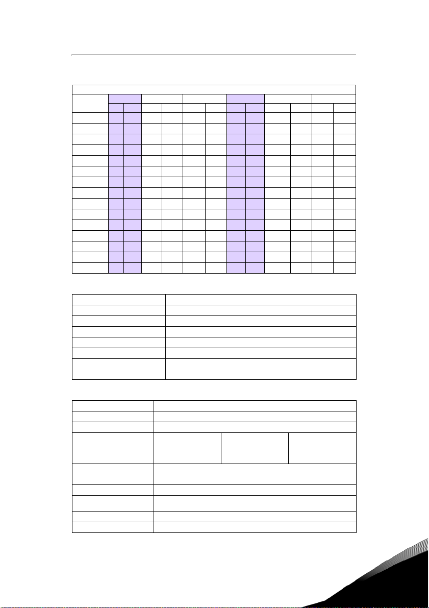
2.2 Power and Current Ratings
Vacon 0500 3L XXXX 5 (460 Vac Ratings)
Model number
0009 5 5 4128.88.97.6 3 2.2 7.2 5.6 5.1 4.8
0012 5
0016 5
0023 5
0031 5
0037 5
0043 5
0061 5
0071 5
0086 5
0105 5
0140 5
0168 5
0205 5
0240 5
2.3 Environmental Specifications
Operating temperature 0 °C to +40 °C (32 °F to 104 °F)
Storage temperature –20 °C to +65 °C (-4 °F to 149 °F)
Humidity 0% to 95% non-condensing
Altitude 1000 m (3300 ft) without derating
Maximum vibration per EN50178 (1g @ 57-150 Hz)
Acoustic noise 80 dba sound power at 1 m (3 ft), maximum
Cooling
2.4 Electrical Specifications
Input voltage Vacon 0500 models: 380-460 Vac, 3 phase, +/- 15%
Line frequency 50 / 60 Hz ±2 Hz
Source kVA (maximum) 10 times the unit rated kVA, 65kA maximum (see note below)
DC bus voltage for:
Overvoltage trip
Dynamic brake activation
Nominal undervoltage (UV)
trip
Control system
Output voltage 0 to 100% of line voltage, three-phase
Overload capacity
Frequency range 0.1 to 400 Hz
Frequency stability 0.1 Hz (digital), 0.1% (analog) over 24 hours +/- 10 °C
Normal Duty Input current (A) Output current (A) Heavy Duty Input current (A) Output current (A)
HP kW 380 Vac 460 Vac 380 Vac 460 Vac HP kW 380 Vac 460 Vac 380 Vac 460 Vac
7.5 5.5 15 12.8 12 11 5 4 12 8.8 8.9 7.6
10 7.5 19.7 16.3 15.6 14 7.5 5.5 15 12.8 12 11
15 11 30.9 25.8 23 21 10 7.5 19.7 16.3 15.6 14
20 15 40 33.3 31 27 15 11 30.9 25.8 23 21
25 18 46.3 40 37 34 20 15 40 33.3 31 27
30 22 57.5 47.8 43 40 25 18 46.3 40 37 34
40 30 73.2 62.4 61 52 30 22 57.5 47.8 43 40
50 37 82 78 71 65 40 30 73.2 62.4 61 52
60 45 94 80 86 77 50 37 82 78 71 65
75 55 114 99 105 96 60 45 94 80 86 77
100 75 149 129 140 124 75 55 114 99 105 96
125 90 168 156 168 156 100 75 140 124 140 124
150 110 205 180 205 180 125 90 168 156 168 156
200 132 240 240 240 240 150 110 205 180 205 180
4 kW/5 HP models: Natural convection
5.5 to 132 kW/7.5 to 200.0 HP models: Forced air (temperature-controlled
external fa n)
4-132 kW/5-200 HP
230 Vac models
406 Vdc
388 Vdc
199 Vdc
V/Hz or Sensorless Vector Control (SVC)
Carrier frequency = 1 - 16 kHz, programmable; 8 kHz max. for 90-132 kW/125200 HP models
120% of rated RMS current for 60 seconds (normal duty rating)
150% of rated RMS current for 60 seconds (heavy duty rating)
460 Vac models
814 Vdc
776 Vdc
397 Vdc
24-hour support +358 (0)40 837 1150 • Email: vacon@vacon.com
2
Page 16

15 z vacon technical characteristics
Frequency setting
Note:
Unit Rated kVA = rated Voltage x rated Current x 1.732
By key pad, or b y extern al signa l (0 to 5 Vdc; 0 to 10 Vdc; 0/4 to 20 mA) or by pulse
train up to 100kHz
2.5 Control Features Specifications
Vin1 reference input
Vin2 reference input
Cin re ference i nput
Reference voltage 10 Vdc (10 mAdc maximum)
Digital inputs - 10
Digital supply voltage 24 Vdc (150 mAdc maximum)
Preset frequencies 4 inputs for 15 preset frequencies (selectable)
Digital outputs
Digital pulse train output Open collector output pulse train proportional to o utput frequency
Vmet analog output 0 to 10 Vdc (5 mAdc maximum)
Imet analog output 0/4-20 mAdc output into a 500 Ω load (maximum)
DC holding / injection braking
Current limit Four quadrant adjustable from 5 to 150%
Speed ramps Primary and alternate adjustable from 0.1 to 3200.0 seconds
Voltage boost Adjustable fixed boost or adjustable auto boost
Voltage characteristic V/Hz: Linear, pump, fan, or 2-piece linear. Also sensorless vector (SVC).
Timed overload
Protective features
Program Sequence Logic
Controller (PSLC)
PID Feedback
Serial communications Modbus, DeviceNet option, Ethernet IP option, Modbus TCP/IP option
0-5/10 Vdc, 0/4-20 mAdc (250 Ω load)
6FS pulse train input from another drive, 0-1/10/100 kHz pulse input, inverted
function, 0-5-10 bipolar input, broken wire detection. Span and offset adjustment.
0-5/10 Vdc, 0-5-10 bipolar input, inverted function, broken wire detection, span
and offset adjustment. Programmable for frequency reference, current limit
input, or feedback signal.
0/4-20 mAdc (50 Ω load), inverted function, span and offset adjustment.
Programmable for frequency reference, current limit input, or feedback signal.
Off=0 to 3 Vdc; On=10 to 32 Vdc (pull-up logic), selectable between pull-up and
pull-down logic
2 SPDT relay outputs - 130 Vac, 1 A/250 Vac, 0.5 A
2 open collector outputs 50 mA per device; 2 optional relays; optional encoder
interface
At start, stop, by frequency with adjustable current level and time or continuous
DC injection by digital input.
Adjustable inverse time trip (shear pin, 30 seconds, 60 seconds, 5 minutes), for
standard or inverter-duty motors
Overcurrent, overvoltage fault, ground fault, short circuit, dynamic brake
overload, drive temperature, power wiring fault, drive timed overload, input
voltage quality, overvoltage ridethrough
25-step (with ability to branch), PLC-type functionality that can control speed,
direction, and ramps based on time, analog input, digital input, or pulse input.
Addressable outputs and real-time operations possible. See “Using the Vacon
500x Program Sequencer” on page 98.
Process control available with the use of a customer-supplied transd ucer, either
0-10 Vdc, 4-20 mA, or optical encoder input to the drive. Includes an optional sleep
mode, activated when the loop is satisfied.
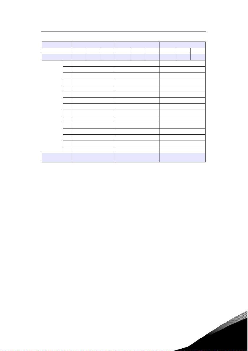
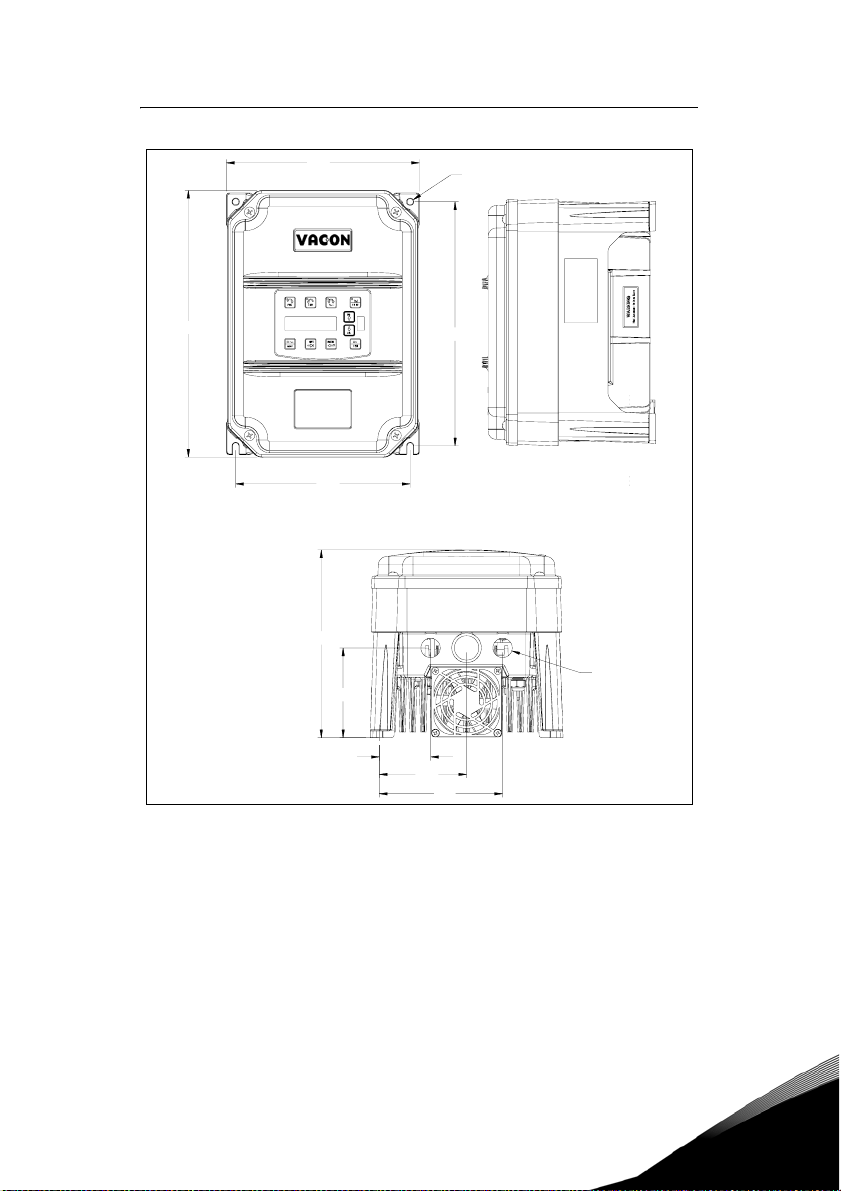
2.6 Dimensions and Weights
Table 1 lists dimensions and weights for the Vacon 500x frame size 1, 2, and 3 models. Dimensions and
weights for the Vacon 500x frame size 4 and 5 models are shown in Table 2 on page 17.
2
See Figures 1, 1, 2, 3, 4, and 5 on pages 18 - 22 for locations of dimensions. Dimensions A through Q are in
inches / millimeters (in/mm). Weight is in pounds / kilograms (lb/kg).
Tel. +358 (0)201 2121 • Fax +358 (0)201 212205
Page 17
technical characteristics vacon z 16
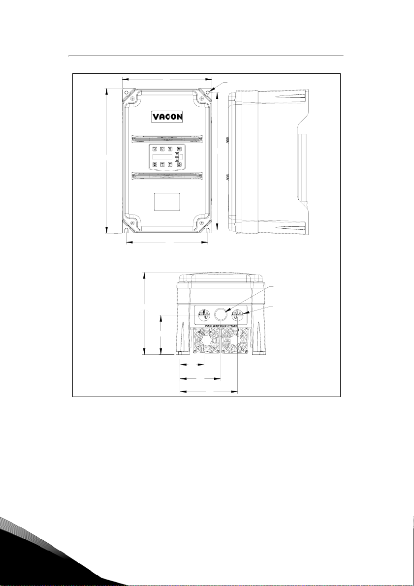
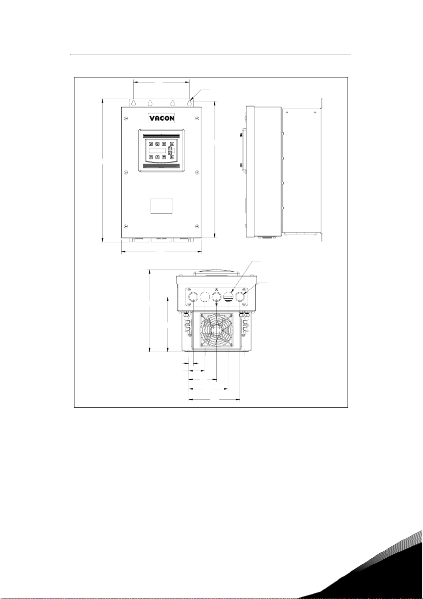
Frame 1 2 3
Voltage 230 Vac 460 Vac 230 Vac 460 Vac 230 Vac 460 Vac
Horsepower 5-7.5 5-10 10-15 15-50 20-25 40-50
A 12.01 (305) 17.38 (441) 20.19 (513)
B 8.72 (221) 10.75 (273) 11.25 (286)
C 8.49 (216) 7.91 (201) 11.73 (298)
D 11.03 (280) 16.50 (419) 19.25 (489)
E 7.88 (200) 9.76 (248) 7.88 (200)
Dimensions
in (mm)
(See Vacon
diagrams
on pages 18
through 22)
F 0.28 (7) 0.41 (10) 0.28 (7)
G 4.05 (103) 4.72 (120) 7.78 (198)
500x
HN/A N/A N/A
J 2.31 (59) 2.88 (73) 0.65 (17)
K 3.94 (100) 4.84 (123) 2.29 (58)
L 5.56 (1.41) 6.88 (175) 3.95 (100)
M 0.88 (22) 1.38 (35) 1.69 (43)
N N/A 1.13 (29) 0.88 (22)
P N/A N/A 5.60 (142)
Q N/A N/A 7.24 (184)
Weig ht
lb (kg)
Table 1: Dimensions and Weights for Frame Sizes 1 - 3
14.0 (6.35) 29.5 (13.38) 50.0 (22.68)
24-hour support +358 (0)40 837 1150 • Email: vacon@vacon.com
2
Page 18

17 z vacon technical characteristics
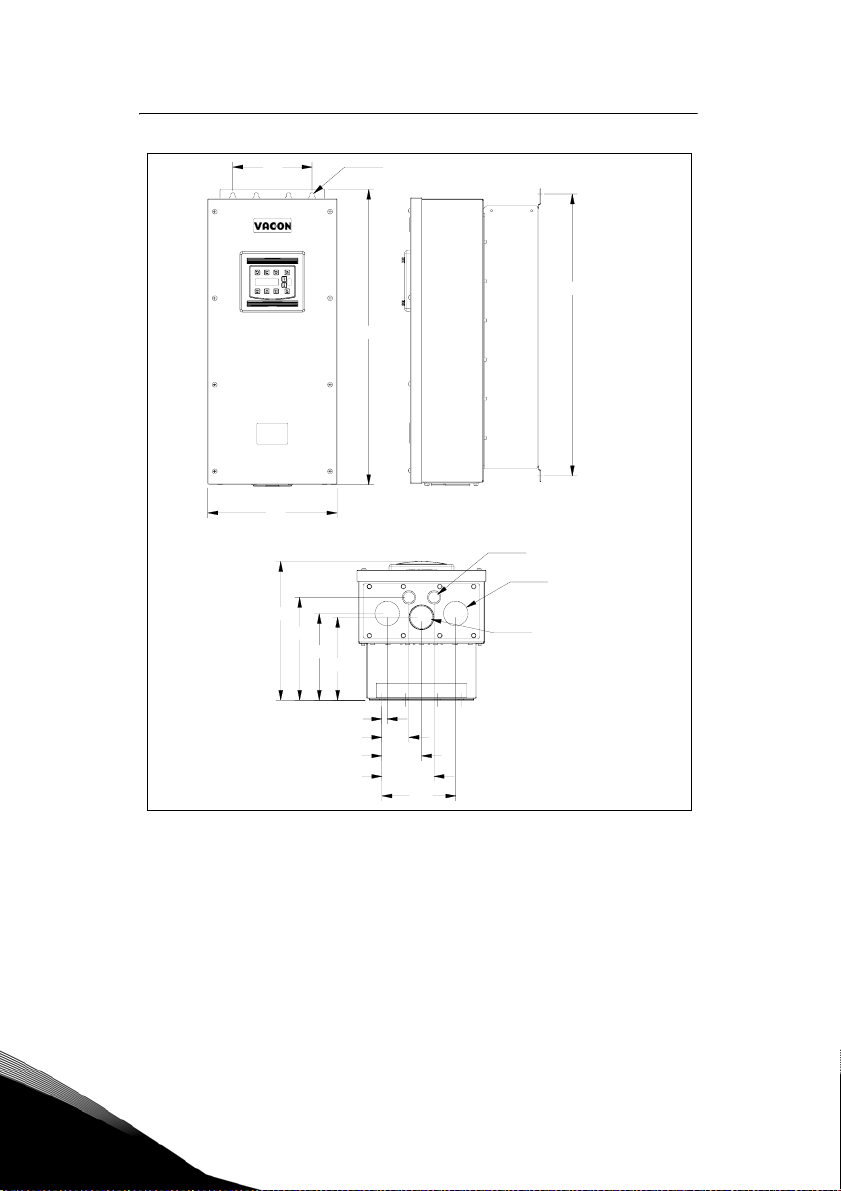
Frame 4 5
Volta ge 460 Va c 46 0 Vac
Horsepower 60-100 125-200
A 29.35 (745) 51.02 (1296)
B 12.84 (326) 16.31 (414)
C 13.80 (351) 16.88 (429)
D 28.00 (711) 45.77 (1163)
E 7.88 (200) 7.65 (194)
F 0.42 (11) 0.42 (11)
G 8.63 (219) 12.57 (319)
Dimensions
in (mm)
(See Vacon 500x
diagrams on pages 21 -
22)
Weig ht
lb (kg)
Table 2: Dimensions and Weights for Frame Sizes 4-5
H 8.26 (210) 11.10 (282)
J 0.53 (13) 0.20 (5)
K 2.69 (68) 2.32 (59)
L 3.94 (100) 3.82 (97)
M 2.44 (62) 2.94 (75)
N 0.88 (22) 0.88 (22)
P 5.19 (132) 5.32 (135)
Q 7.35 (187) 7.45 (189)
R 10.23 (260) N/A
S 1.94 (49) 1.86 (47)
95.0 (43.10)) 305.0 (138.35)
2
Tel. +358 (0)201 2121 • Fax +358 (0)201 212205
Page 19
technical characteristics vacon z 18
B
A
X
series
E
C
G
F
D
M
J
K
L
Figure 1: Vacon 500x Frame Size 1 Models
24-hour support +358 (0)40 837 1150 • Email: vacon@vacon.com
2
Page 20
19 z vacon technical characteristics
B
A
X
series
E
C
G
J
K
F
D
N
M
L
2
Figure 2: Vacon 500x Frame Size 2 Models
Tel. +358 (0)201 2121 • Fax +358 (0)201 212205
Page 21
technical characteristics vacon z 20
E
A
X
series
B
C
G
J
K
F (8) PLACES
D
M (2) PLACES
N (3) PLACES
L
P
Q
Figure 3: Vacon 500x Frame Size 3 Models
24-hour support +358 (0)40 837 1150 • Email: vacon@vacon.com
2
Page 22
21 z vacon technical characteristics
E F (8) PLACES
D
A
X
series
B
N (2) PLACES
M(2) PLACES
C
R
G
H
S (1) PLACES
2
J
K
L
P
Q
Figure 4: Vacon 500x Frame Size 4 Models
Tel. +358 (0)201 2121 • Fax +358 (0)201 212205
Page 23

technical characteristics vacon z 22
E F (8) PLACES
A
X
series
B
C
G
H
J
K
L
P
Q
Figure 5: Vacon 500x Frame Size 5 Models
D
N(2) PLACES
M (2) PLACES
S (1) PLACE
24-hour support +358 (0)40 837 1150 • Email: vacon@vacon.com
2
Page 24
23 z vacon receiving and installation
3. RECEIVING AND INSTALLATION
3.1 Preliminary Inspection
Before storing or installing the Vacon 500X drive, thoroughly inspect the device for possible shipping
damage. Upon receipt:
1. Remove the drive from its package and inspect exterior for shipping damage. If damage is apparent, notify
the shipping agent and your sales representative.
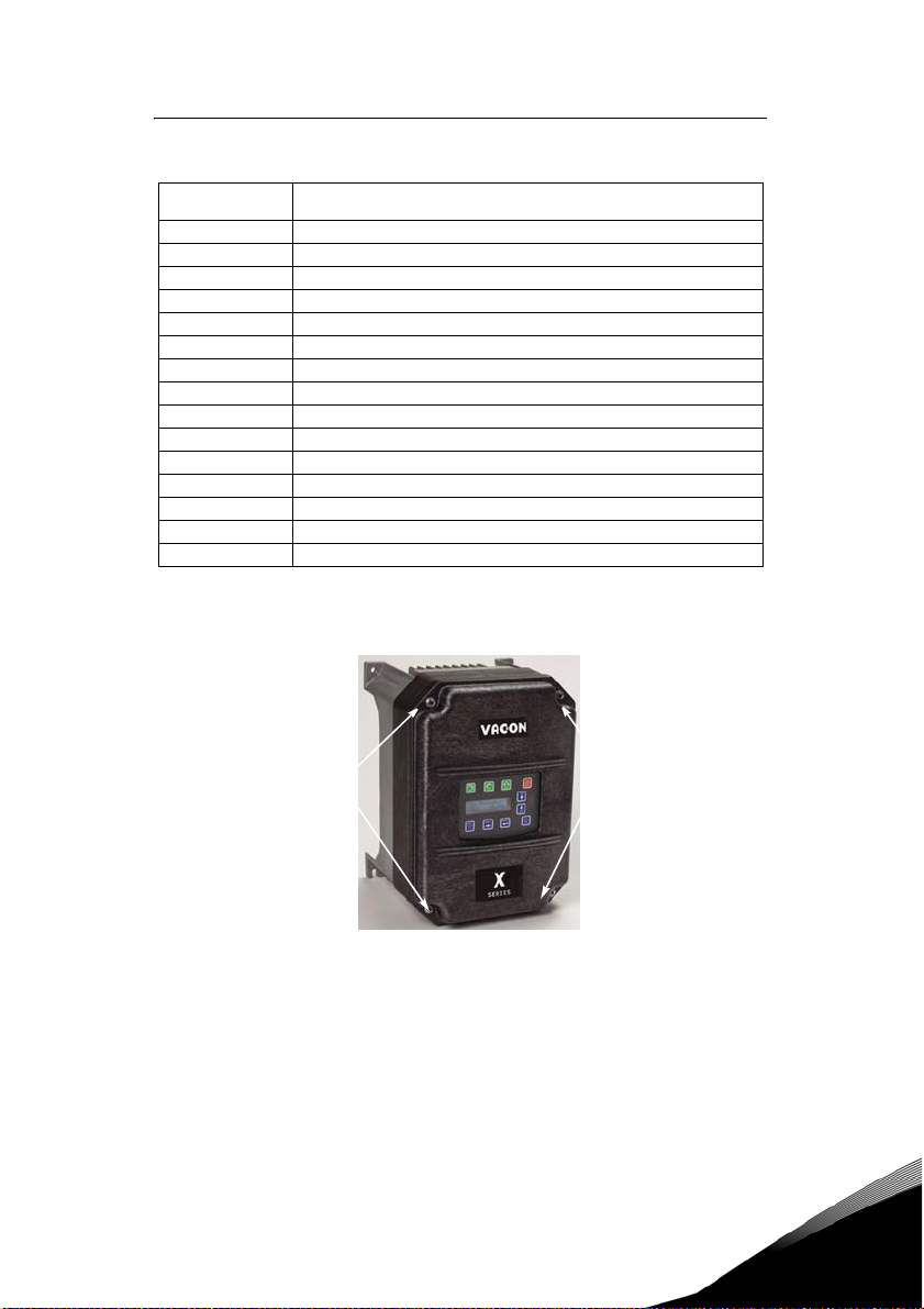
2. Remove the cover and inspec t the drive for any apparent damage or foreign objects. (See F igure 6 on page
24 for lo cations of cover s crews.) E nsure that all mo unting h ardware and te rminal conn ection h ardware
is properly seated, securely fastened, and undamaged.
3. Read the technical data label affixed to the dri ve and ensure that the correct horsepower and input voltage
for the application has been purchased.
4. If you will be storing the drive after receipt, place it in its original packaging and store it in a clean, dry
place free from direct sunlight or corrosive fumes, where the ambient temperature is not less than -20 °C
(-4 °F) or greater than +65 °C (+149 °F).
EQUIPMENT DAMAGE HAZARD
Do not operate or install any drive that appears damaged.
Failure to follow this instruction can result in injury or equipment damage.
CAUTION
RISQUE DE DOMMAGES MATÉRIELS
Ne faites pas fonctionner et n’installez pas tout variateur de vitesse qui semble
être endommagé.
Si cette directive n’est pas respectée, cela peut entraîner des blessures
ATTENTION
3.2 Installation Precautions
Improper installation of the Vacon 500x drive will greatly reduce its life. Be sure to observe the following
precautions when selecting a mounting location. Failure to observe these precautions may void the
warranty! See the inside front cover of this manual for more information about the warranty.
• Do not install the drive in a place subjected to high temperature, high humidity, excessive
vibration, corrosive gases or liquids, or airborne dust or metallic particles. See Chapter 2 for
temperature, humidity, and maximum vibration limits.
• Do not mount the drive near heat-radiating elements or in direct sunlight.
• Mount the drive vertically and do not restrict the air flow to the heat sink fins.
• The drive generates heat. Allow sufficient space around the unit for heat dissipation. See
“Dissipation Requirements” on page 24.
corporelles ou des dommages matériels.
3
Tel. +358 (0)201 2121 • Fax +358 (0)201 212205
Page 25
receiving and installation vacon z 24
3.3 Dissipation Requirements
Model
0009 5 91
0012 5
0016 5
0023 5
0031 5
0037 5
0043 5
0061 5
0071 5
0086 5
0105 5
0140 5
0168 5
0205 5
0240 5
3.4 Cover Assembly and Torque Specifications
Figure 6 shows the locations of the Vacon 500x cover screws. The torque range for the Size 1 cover is 1826 in/lbs.
Required Dissipation for Models Entirely Inside an Enclosure at Rated
Current, 3KHz Carrier Frequency (Watts)
114
155
304
393
459
458
695
834
776
988
1638
1656
1891
2302
Cover screw locations
Torque specifications for control terminals and power terminals are listed in “General Wiring Information”
on page 27 .
Figure 6: Vacon 500x Cover Assembly and Screw Locations
Cover screw locations
3.5 Serial Number Label
VACON Plc warrants all AC drives for three years from date of manufacture, or two years from the date of
installation, whichever comes first. For a more detailed description of VACON Plc warranty policy, see the
inside front cover of this manual, or visit the web site at http://www.vacon.com. To determine if your drive
is within the warranty time frame, find the bar code label or look in the lower left of the technical
nameplate. The serial number can be broken down as follows:
24-hour support +358 (0)40 837 1150 • Email: vacon@vacon.com
3
Page 26

25 z vacon receiving and installation
yywwxxxx = yy...year of manufacture
3.6 Conduit Usage
The Vacon 500x drive in the NEMA 4x / IP66 enclosure is rated for 1000 psi washdown from 6 inches. To
keep this rating, the use of a sealed conduit is required. The use of a Romex-type conduit will not prevent
water entry into the enclosure. If the approved conduit is not used, all warranty claims against water
damage will be void.
3.7 Condensation
The washdown process of an Vacon 500x drive may create a temperature and humidity change in and
around the drive. If the unit is mounted in a cool environment and washed down with higher-temperature
water, as the drive cools to room temperature, condensation can form inside the drive, especially around
the display. To prevent this from happening, avoid using sealed connectors around rubber-coated cables
to seal the drive. These do not allow any air transfer and hence create a level of condensation and humidity
that exceeds the drive’s rating.
ww...week of manufacture
xxxx...sequential number drive during that week
3
Tel. +358 (0)201 2121 • Fax +358 (0)201 212205
Page 27

receiving and installation vacon z 26
24-hour support +358 (0)40 837 1150 • Email: vacon@vacon.com
3
Page 28

27 z vacon connections
4. CONNECTIONS
HAZARDOUS VOLTAGE
• Read and understand this manual in its entirety before installing or operating the Vacon 500x AC
drive. Installation, adjustment, repair, and maintenance of these drives must be performed by
qualified personnel.
• Disconnect all power before servicing the drive. WAIT 5 MINUTES until the DC bus capacitors
discharge.
• DO NOT short across DC bus capacitors or touch unshielded components or terminal strip screw
connections with voltage present.
• Install all covers before applying power or starting and stopping the drive.
• The user is responsible for conforming to all applicable code requirements with respect to
grounding all equipment.
• Many parts in this drive, including printed circuit boards, operate at line voltage. DO NOT TOUCH.
DANGER
DANGER
Use only electrically-insulated tools.
Before servicing the drive.
• Disconnect all power.
• Place a “DO NOT TURN ON” label on the drive disconnect.
• Lock the disconnect in the open position.
Failure to observe these precautions will cause shock or burn, resulting in severe personal
injury or death.
TENSION DANGEREUSE
• Lisez et comprenez ces directives dans leurs intégralité avant d’installer ou de faire fonctionner le
variateur de vitesse Vacon 500x. L’installation, le réglage, les réparations et l’entretien des ces
variateurs de vitesse doivent être effectuées par du personnel qualifié.
• Coupez toutes les alimentations avant de travailler sur le variat eur de vitesse. ATTENDEZ CINQ
MINUTES pour que la décharge des condensateurs du bus cc s’effectue.
• NE court-cuitez PAS les condensateurs du bus cc ou ne touchez pas aux composantes non blindées ou
aux connexions des vis du bornier si l’appareil est sous tension.
• Installez tous les couvercles avant de mettre le variateur de vitesse sous tension, de le mettre en
marche ou de l’arrêt er.
• L’utilisateur est responsable de la conformité avec tous les codes électriques en vigueur concernant la
mise à la terre de tous les appareils.
• De nombreuses pièces de ce variateur de vitesse, y compris les cartes de circuits imprimés,
fonctionnent à la tension du secteur. N’Y TOUCHEZ PAS. N’utilisez que des outils dotés d’une isolation
électrique.
Avant tout entretien ou r éparation sur le variateur de vitesse:
• Coupez toutes les ali mentations.
• Placez une étiquette «NE PAS METTRE SOUS TENSION» sur le sectionneur du variateur de vitesse.
• Verrouillez le sectionneur en position ouverte.
Si ces précautions ne sont pas respectées, cela causera une électrocution ou des brûlures, ce
qui entraînera des blessures graves ou la mort.
4
4.1 Introduction
This chapter provides information on connecting power and control wiring to the Vacon 500X AC drive.
4.2 General Wiring Information
4.2.1 Wiring Practices
When making power and control connections, observe these precautions:
• Never connect input AC power to the motor output terminals T1/U, T2/V, or T3/W. Damage to the
drive will result.
• Power wiring to the motor must have the maximum possible separation from all other power
wiring. Do not run in the same conduit; this separation reduces the possibility of coupling
electrical noise between circuits.
• Cross conduits at right angles whenever power and control wiring cross.
Tel. +358 (0)201 2121 • Fax +358 (0)201 212205
Page 29

connections vacon z 28
• Good wiring practice also requires separation of control circuit wiring from all power wiring.
Since power delivered from the drive contains high frequencies which may cause interference
with other equipment, do not run control wires in the same conduit or raceway with power or
motor wiring.
4.2.2 Considerations for Power Wiring
Power wiring refers to the line and load connections made to terminals L1/R, L2/S, L3/T, and T1/U, T2/V,
T3/W respectively. Select power wiring as follows:
1. Use only UL-recognized wire.
2. Wire voltage rating must be a minimum of 300 V for 230 Vac systems and 600 V (Class 1 wire) for 460 or
575 Vac systems.
3. Wire gauge must be selected based on 125% of the continuous input current rating of the drive. Wire
gauge must be selected from wire tables for 75 °C insulation rating, and must be of copper construction.
The 230 V 5.5 kW/7.5 HP and 11 kW/15 HP models, and the 460 V 22 kW/30 HP models require 90 °C wire
to meet UL requirements. See Chapter 2 for the continuous output ratings for the drive.
4. Grounding must be in accordance with NEC and CEC. If multiple Vacon 500x drives are installed near each
other, each must be connected to ground. Take care not to form a ground loop.
See Table 1 for a summary of power terminal wiring specifications.
Vacon 500x Size / Models Specifications
16 in-lbs nominal torque
Size 1
Size 2
Size 3
Size 4
Size 5
Table 1: Vacon 500x Power Terminal Wiring Specifications
Note: Wire type not specified by the manufacturer. Some types of wire may not fit within the constraints of
the conduit entry and bend radius inside the drive.
18 in-lbs maximum torque
8-18 awg wire
5/16” (0.3125”) strip length
30 in-lbs nominal torque
6-8 awg wire
3/8” (0.38”) strip length
35 in-lbs nominal torque
3 awg wire
65 in-lbs nominal torque
3/0 awg wire max
132 in-lbs nominal torque
250MCM wire max
4.2.3 Considerations for Control Wiring
Control wiring refers to the wires connected to the control terminal strip. Select control wiring as follows:
1. Shielded wire is recommended to prevent electrical noise interference from causing improper operation
or nuisance tripping.
2. Use only UL recognized wire.
3. Wire voltage rating must be at least 300 V for 230 Vac systems. It must be at least 600 V for 460 systems.
See Table 2 below for a summary of power terminal control wiring specifications.
Vacon 500x Size / Models Specifications
All Sizes / Models
Table 2: Vacon 500x Control Wiring Specifications
4.4 in-lbs maximum torque
12-24 awg wire
9/32” strip length
4.3 Input Line Requirements
4.3.1 Line Voltage
See “Power and Current Ratings” on page 14 for the allowable fluctuation of AC line voltage for your
particular Vacon 500x model. A supply voltage above or below the limits given in the table will cause the
drive to trip with either an overvoltage or undervoltage fault.
or
24-hour support +358 (0)40 837 1150 • Email: vacon@vacon.com
4
Page 30
29 z vacon connections
Exercise caution when applying the Vacon 500x AC drive on low-line conditions.
For example, an Vacon 500x 2000 series unit will operate properly on a 208 Vac line, but the maximum
output voltage will be limited to 208 Vac. If a motor rated for 230 Vac line voltage is controlled by this drive,
higher motor currents and increased heating will result.
Therefore, ensure that the voltage rating of the motor matches the applied line voltage.
4.3.2 Line Capacity
If the source of AC power to the Vacon 500x AC drive is greater than 10 times the kVA rating shown in Tabl e
3 below, an isolation transformer or line reactor is recommended. Consult the factory for assistance in
sizing the reactor.
Drive kW 4 5.5 7.5 11 15 18.5 18.5 30 37 45 55 75 90 110 132
Drive HP 5 7.5 10 15 20 25 30 40 50 60 75 100 125 150 200
Tran sfor mer
kVA
Table 3: Vacon 500x Line Capacity (kVA)
Note: Vacon 500x AC drive devices are suitable for use on a circuit capable of delivering not more than
65,000 rms symmetrical amperes at 10% above the maximum rated voltage.
4.3.3 Phase Imbalance
Phase voltage imbalance of the input AC source can cause unbalanced currents and excessive heat in the
drive’s input rectifier diodes and DC bus capacitors. Phase imbalance can also damage motors running
directly across the line. The phase imbalance should not exceed 2% of the voltage rating; if it does, the
drive should be derated as a single-phase drive.
CAUTION
9 13 18 23 28 36 42 57 70 90 112 150 180 220 250
EQUIPMENT DAMAGE HAZARD
Never use power-factor correction capacitors on motor terminals T1/U, T2/V, or T3/W of the
Vacon 500x AC drive. Doing so will damage the semiconductors.
Failure to follow this instruction can result in injury or equipment damage.
4
RISQUE DE DOMMAGES MATÉRIELS
Ne raccordez jamais de condensateurs de correction du facteur de puissance aux bornes T1/
U, T2/V, ou T3/W du moteur du variateur de vitesse Vacon 500x. Car cela endommagera les
semiconducteurs.
Si cette directive n’est pas respectée, cela peut entraîner des blessures corporelles ou des
ATT ENT ION
dommages matériels.
4.3.4 Single-phase Operation
Vacon 500x AC drive 230 Vac, 4-kW/5-HP models are designed for both three-phase and single-phase input
power. If one of these models is operated with single-phase power, use any two line input terminals. The
output of the device will always be three-phase.
The safe derating of the Vacon 500x series of drives is 50% of the nominal current (kW/HP) rating. Consult
the factory with the particular application details for exact derating by model.
4.3.5 Ground Fault Circuit Interrupters (GFCI)
The GFCI breakers are designed for residential use to protect personnel from stray currents to ground.
Most GFCI breakers will shut off at 5 mA of leakage. It is not uncommon for an AC drive to have 30 to 60
mA of leakage.
Tel. +358 (0)201 2121 • Fax +358 (0)201 212205
Page 31

connections vacon z 30
4.3.6 Motor Lead Length
VACON Plc recommends that the total lead length should not exceed the motor manufacturer’s guidelines.
Line disturbance and noise can be present in motor wiring of any distance. As a rule of thumb, any noninverter duty motor should have a reactor or filter added when the motor lead length exceeds 150 feet. The
carrier frequency for the drive should also be reduced using parameter 803 (PWM Frequency).
Nuisance trips can occur due to capacitive current flow to ground. These currents can cause shock to
personnel and can create problems within the motor. Care should be taken when working in these areas.
Some applications can have a restricted lead length because of type of wire, motor type, or wiring
placement. Consult the factory and the motor manufacturer for additional information.
4.3.7 Using Output Contactors
Contactors in the output wiring of an AC drive may be needed as part of the approved safety circuit.
Problems can arise if these contactors are opened for the safety circuit and the drive is left in run mode of
operation. When the contactor is open, the drive is in a no-load, no-resistance state, but is still trying to
supply current to the motor. However, when the contactor closes, the drive sees the motor resistance and
instantly demands current. This inrush of current when the contactor closes can fault or cause failure to
the drive.
To prevent problems, interlock an auxiliary contact to the drive’s Run or Enable circuit to stop the drive
when the contactor opens. In this way, the drive will be disabled and no inrush will occur when the
contactor is closed again.
4.4 Terminals Found on the Vacon 500x Power Board
4.4.1 Description of the Terminals
Table 4 describes the Vacon 500x power terminals.
Terminal Description
L1/R
These terminals are the line connections for input power. (Single-phase 230 Vac,
L2/S
models connect to any two of these terminals.)
L3/T
T1/U
T2/V
These terminals are for motor connections.
T3/W
Table 4: Description of Vacon 500x Power Terminals
4 kW/5 HP
24-hour support +358 (0)40 837 1150 • Email: vacon@vacon.com
4
Page 32

31 z vacon connections
Note that earth ground is on the terminal strip (see Figure 7). Dynamic brake (DB) connections are not on
the terminal strip, but on “fast on” (spade) connectors for models up to 18.5 kW/30 HP, and on the terminal
strip for models 30 kW/40 HP and larger. See page33 for specific information about dynamic braking.
Figure 7: Vacon 500x Power Terminals
4
Tel. +358 (0)201 2121 • Fax +358 (0)201 212205
Page 33

connections vacon z 32
Figure 8: Power Terminals on Higher-kW/HP Models
4.4.2 Typical Power Connections
See Section 4.3 starting on page 28 for input line requirements.
Note that when testing for a ground fault, do not short any motor lead (T1/U, T2/V, or T3/W) back to an input
phase (L1/R, L2/S, or L3/T).
It is necessary to provide fuses and a disconnect switch for the input AC line in accordance with all
applicable electrical codes. The Vacon 500x AC drive is able to withstand a 150% overload for 60 seconds
for heavy duty rating, and 120% overload for normal duty rating.
The fusing and input protection of the drive must always meet UL, NEC (National Electric Code), and CEC
(Canadian Electric Code) requirements. All fuse ratings included in Table 5 below are for reference only and
do not supersede code requirements. The recommended supplier is Bussman.
Model Number
0009 5
0012 5
0016 5
0023 5
0031 5
0037 5
0043 5
0061 5
0071 5
Table 5: Fuse Ratings
Fuse S ize
380 Vac
Fuse Siz e
JJS
15 15
20 20
25 20
40 35
50 40
60 50
80 60
100 80
110 100
460 Vac
JJS
24-hour support +358 (0)40 837 1150 • Email: vacon@vacon.com
4
Page 34

33 z vacon connections
Fuse S ize
Model Number
0086 5 125 100
0105 5
0140 5
0168 5
0205 5
0240 5
Table 5: Fuse Ratings
380 Vac
Fuse Siz e
JJS
150 125
200 175
225 200
250 225
300 300
460 Vac
JJS
4.5 Dynamic Braking
The Vacon 500x AC drive is supplied with an integrated dynamic braking (DB) resistor, and is designed to
have adequate dynamic braking for most applications. In cases where short stopping times or high inertia
loads require additional braking capacity, install an external resistor.
Note: For Size 4 (45-75 kW/60-100 HP) and Size 5 (90-132 kW/125-200 HP) models, additional external
dynamic braking requires a kit that provides the connections to the braking transistors. The XDBKITS4 and
XDBKITS5 kits can be purchased through local distributors.
If an external resistor is used for dynamic braking, the internal resistor must be disconnected. To install
an external resistor, first disconnect the internal DB resistor (or resistors in 460 and 575 Vac models) and
properly terminate the wires leading to it. Then connect the external resistor fast-on terminals where the
internal resistor had been connected.
Changes to parameter 410 must be made when using external DB resistors.
Verify with the manufacturer of the selected resistor that the resistor is appropriate for your application.
Contact VACON Plc Electronic Application Engineering for further assistance with other possible sizing
limitations.
Refer to Tab le 6 for information about dynamic braking capacity for each Vacon 500x model.
Model KW
0009 5
0012 5
0016 5
0023 5
0031 5
0037 5
0043 5
0061 5
0071 5
0086 5
0105 5
0140 5
0168 5
0205 5
0240 5
Table 6: Vacon 500x Dynamic Braking Capacity
Standard
Resistance
3.7 120 136% 100 6,084 163%
5.5 120 91% 75 8,112 145%
7.5 120 68% 75 8,112 109%
11 120 45% 47 12,944 116%
15 120 34% 47 12,944 87%
18 120 27% 47 12,944 69%
22 120 23% 39 15,600 70%
29.8 60 34% 20 30,420 102%
37.3 60 27% 20 30,420 82%
45 60 23% 15 40,560 91%
55 60 18% 10 60,840 109%
75 60 14% 10 60,840 82%
90 60 11% 10 60,840 65%
110 60 9% 10 60,840 54%
132 60 7% 10 60,840 41%
Standard DB %
of Drive
Min. Allowed
Res.
Max. Peak
Watt s
Max. Ext. DB % of
Drive
4
Tel. +358 (0)201 2121 • Fax +358 (0)201 212205
Page 35

connections vacon z 34
4.6 Terminals Found on the Vacon 500x Control Board
4.6.1 Description of the Control Terminals
Figure 9 shows the control terminals found on the I/O board of the Vacon 500x AC drive. See page 15 for
specifications. Table 7 on page 36 shows how to use the control terminals for preset speeds.
The drive’s control terminals are referenced to earth ground through a resistor / capacitor network. Use
caution when connecting analog signals not referenced to earth ground, especially if the communications
port (J3) is being used. The J3 port includes a common reference that can be connected to earth ground
through the host PLC or computer.
Figure 9: Vacon 500x Control Terminals
24-hour support +358 (0)40 837 1150 • Email: vacon@vacon.com
4
Page 36

35 z vacon connections
4.6.2 Typical Connection Diagrams for Digital Inputs
Typical connection for 2-wire control
Typical connection for 3-wire control
Figure 10: Connections for 2-wire and 3-wire Control
4
Tel. +358 (0)201 2121 • Fax +358 (0)201 212205
Page 37

connections vacon z 36
Table 7: Selection of Preset Speeds
PS4
PS3
PS2
DI1
DI4
DI3
DI2
REV
R/J
FWD
PS1
Figure 11: Connections for Preset Speeds
DI5
+24V
MOL
PS4
PS2
PS3
Dcom
(Bit 4)
(Bit 3)
0000
0001
0010
0011
0100
0101
0110
0111
1000
1001
1010
1011
1100
1101
1110
1111
PS1
(Bit 2)
(Bit 1) Speed Selected
Normal reference
speed as defined by
parameters 201 (Input
Mode) and 204 (Ref
Select)
Preset frequency F1
(parameter 303)
Preset frequency F2
(parameter 304)
Preset frequency F3
(parameter 305)
Preset frequency F4
(parameter 306)
Preset frequency F5
(parameter 307)
Preset frequency F6
(parameter 308)
Preset frequency F7
(parameter 310)
Preset frequency F8
(parameter 311)
Preset frequency F9
(parameter 312)
Preset frequency F10
(parameter 313)
Preset frequency F11
(parameter 314)
Preset frequency F12
(parameter 315)
Preset frequency F13
(parameter 316)
Preset frequency F14
(parameter 317)
Preset frequency F15
(parameter 318)
24-hour support +358 (0)40 837 1150 • Email: vacon@vacon.com
4
Page 38

37 z vacon connections
4.6.3 Typical Connection Diagrams for Analog Inputs
Figure 12: Connections for Speed Potentiometer
4
Figure 13: Connections for Process Signal
Tel. +358 (0)201 2121 • Fax +358 (0)201 212205
Page 39

connections vacon z 38
4.6.4 Typical Connection Diagrams for Analog Outputs
Figure 14: Connections for Process Meters
24-hour support +358 (0)40 837 1150 • Email: vacon@vacon.com
4
Page 40

39 z vacon operation and programming
5. OPERATION AND PROGRAMMING
5.1 Introduction
The Vacon 500X AC drive is pre-programmed to run a standard, 4-pole AC induction motor. For many
applications, the drive is ready for use right out of the box with no additional programming needed. The
digital keypad controls all operations of the unit. The ten input keys allow “press and run” operation of the
motor (Operation mode) and straightforward programming of the parameters (Program mode)..
Figure 15: The Vacon 500x Keypad
To simplify programming, the parameters are grouped into three levels:
1. Enter Level 1 by pressing the Program (PROG) key at any time. Level 1 allows you to access the most
commonly used parameters.
2. Enter Level 2 by holding down the SHIFT key while pressing the PROG key. Level 2 allows access to all
Vacon 500x parameters, including those in Level 1, for applications which require more advanced
features.
3. Enter Macro mode by holding the Program (PROG) key down for more than 3 seconds. The display then
shows “Hold PROG for Macro Mode.” See Chapter 6, “Using Macro Mode,” starting on page 111, for more
information.
The summary of parameters found before the Table of Contents notes whether a parameter is in Level 1.
“Vacon 500X Parameters” on page 61 gives full information about what level a parameter is in.
Want to get started fast?
5.2 Keypad Operation
Parameter 201, Input Mode (see page 66), determines whether the Vacon 500x AC drive accepts its Run/Stop
and speed commands from the digital keypad or from the input terminals. Table 1 describes the function
of the keys in Operation mode.
See the “Quick Start” section on page 60.
5
Initiates forward run when pressed momentarily. If the drive is running in reverse when
FWD i s pressed, it will decelerat e to zero s peed, change direction, and accelerate to the set
speed. The green FWD designation in the key illuminates whever a FWD command has been
given. When both the FWD and REV lights are on, the DC braking function is active.
Table 1: Function of Keys in Operation Mode (Vacon 500x Running or Stopped)
Tel. +358 (0)201 2121 • Fax +358 (0)201 212205
Page 41

operation and programming vacon z 40
Initiates reverse run when pressed momentarily. If the drive is running in forward when REV
is pressed, it will decelerate to zero speed, change direction, and accelerate to the set
speed. The green REV in the key illuminates whenever a REV command has been issued.
When both the FWD and REV lights are on, the DC braking function is active.
Causes a Ramp-to-Stop when pressed. Programmable to Coast-to-Stop by parameter 401,
Ramp Select
command has been given. If the drive has stopped because of a fault, this indicator flashes
to call attention to the display.
Press the Jog button to enter the Jog mode. The green JOG indicator in the key illuminates
when the drive is in the JOG mode of operation. To jog the motor in either direction, press
either the FWD or REV (if REV is enabled in parameter 202). The motor will operate at the
speed programmed in parameter 303. To exit the Jog mode, press the Jog key again.
When the drive is stopped, pressing this key increases the desired running speed. When the
drive is running, pressing this key increases the actual running speed in 0.1 Hz increments.
Holding the SHIFT key while pressing the UP arrow moves the decimal place to the left with
each press (0.1 Hz, 1.0 Hz, 10.0 Hz increments).
When the drive is stopped, pressing this key decreases the desired running speed. When the
drive is running, pressing the DOWN key decreases the actual running speed in 0.1 Hz
increments. Holding the SHIFT key while pressing the DOWN arrow moves the decimal
place to the right with each press (10.0 Hz, 1.0 Hz, 0.1 Hz increments).
NOTE: The operating speed for the drive is stored on Power Down.
Pressing this key while a parameter is displayed allows that parameter to have its value
changed by use of the UP and DOWN arrow keys. The P indicator flashes to show that the
parameter can be programmed. See also the descriptions for the UP and DOWN arrows
above to see how they work with the SHIFT key.
The Enter key has no function when the drive is running or stopped. The Enter key can be
used to store the speed command so that it is saved through a power-down. To enable this
function, see the description for parameter 802 (Start Options) on page 87.
(page 71). The red STOP indicator in the key illuminates whenever a STOP
Whether the drive is running or stopped, pressing this key places the drive in Program
mode. See Table 2 on page 41 for more information on how t his key functions .
Pressing this key toggles drive control between the LOCal and REMote control modes, as
selected by parameter 201 (Input Mode). It can be configured to shift:
•the Run/Stop command (either FWD or REV)
•the speed reference signal
•both of the above
It can also be set to “disabled,” which is the factory setting. It will operate either in Stop
mode or while the drive is running. If power is removed and reapplied, the memory will
retain the last selected function.
Table 1: Function of Keys in Operation Mode (Vacon 500x Running or Stopped)
24-hour support +358 (0)40 837 1150 • Email: vacon@vacon.com
5
Page 42

41 z vacon operation and programming
Program mode is entered by stopping the drive and pressing the Program (PROG) key for Level 1 access;
or holding down SHIFT while pressing PROG for Level 2 access. Pressing and holding the Enter key and
then pressing the Program key will show only those parameters that have been changed from the factory
defaults. Table 2 describes the function of the keys in Program mode.
Press this key to have the drive enter Program mode and have Level 1 pa rameters available.
(To access Level 2 parameters, hold down SHIFT while pressing this key; to access Macro
mode, hold down the PROG key for more than 3 seconds.) Once Program mode is active,
pressing this key at any time returns the drive to the Operation mode. If an A ccess Code has
been programmed, it must be entered to proceed with programming. See parameter 811
(Access Code) (page 89).
NOTE: To see wh at par amete rs hav e chan ged fro m the factor y defa ult, p ress EN TER + P ROG.
If the display flashes “Factory Defaults,” no parameters have changed.
In the Program mode, pressing this key scrolls forward through the parameters. If the P
indicator is flashing, it increases the value of the parameter. To change the scroll rate, hold
the SHIFT key at the same time to increase the scroll rate; release the SHIFT key to return
to the normal scroll rate. Press the ENTER key to store the new value.
In the Program mode, pressing this key scrolls backward through the parameters. If the P
indicator is flashing, it decreases the value of the parameter. To change the scroll rate, hold
the SHIFT key at the same time to increase the scroll rate; release the SHIFT key to return
to the normal scroll rate. Press the ENTER key to store the new value.
NOTE: If the P indicator on the keypad display is flashing, momentarily pressing and
releasing both the UP and DOWN arrows at the same time restores the parameter to the
factory default value. Press ENTER to store the new value.
Pressing this key while a parameter is displayed allows that parameter to have its value
changed by use of the UP and DOWN arrow keys. The P indicator flashes to show that the
parameter can be programmed. See also the descriptions for the UP and DOWN arrows
above to see how they work with the SHIFT key.
5
This key must be pressed after the value of a parameter has been changed to store the new
value. The display will show “stored” for one second indicating that the new value has been
entered into memory.
N OTE: The Vacon 500x unit all ows you t o view on ly those p aramete rs that h ave chan ged. If you
press keypad keys ENTER and PROGram simultaneously, only those parameters that have
been changed from the factory defaults will be shown.
Table 2: Function of Keys in Program Mode
Tel. +358 (0)201 2121 • Fax +358 (0)201 212205
Page 43

operation and programming vacon z 42
In Fault mode, pressing the UP and DOWN keys allows the operator to view the drive’s
status immediately before the fault occurred. Use the UP and DOWN arrows to scroll
through the status parameters. Press the STOP (Reset) key to return to normal
operation.
See “Troubleshooting” on page 111 for information about viewing Advanced Fault
Codes and understanding error codes.
The red STOP indicator functions as a reset button when in Fault mode. If the drive has
stopped because of a fault, this light flashes to call attention to the display.
Table 3: Function of Keys in Fault Mode
5.3 LCD Displays
The Vacon 500x drive’s digital keypad display provides information such as source of drive control, status,
mode, and access rights.
5.3.1 Control
The first 3 characters of the display show the source of control for the drive:
Display Values Meaning
LOC Local control via the keypad
REM Remote control from the terminal strip
SIO Remote control via the RS485 Serial SIO Link
SQx Control via the Program Sequencer
MEA The Stator Resistance Measurement is armed
5.3.2 Vacon 500x Keypad Status and Warning Messages
Table 4 shows Vacon 500x keypad status messages that may appear during operation:
Message Meaning
Stopped
FWD Accel
REV Accel
FWD Decel
REV Decel
Jog FWD The drive is jogging in the forward direction.
Jog REV The drive is jogging in the reverse direction.
Table 4: Keypad Status States
The drive is not spinning the motor or injecting DC voltage. The dr ive is ready to
run when given the proper signal.
The drive is spinning the motor in the forward direction and the speed of the
motor is increasing.
The drive is spinning the motor in the reverse direction and the speed of the
motor is increasing.
The drive is spinning the motor in the forward direction and the speed of the
motor is decreasing.
The drive is spinning the motor in the reverse direction and the speed of the
motor is decreasing.
24-hour support +358 (0)40 837 1150 • Email: vacon@vacon.com
5
Page 44

43 z vacon operation and programming
Message Meaning
FWD At Spd
REV At Spd
Zero Speed
DC Inject The drive is injecting DC voltage into the motor.
Faulted The drive is faulted.
Reset-Flt The drive is faulted, but has the possibility of being automatically reset.
LS Lockout
Catch Fly The Catch on the Fly functionality is actively searching for the motor frequency.
Forw ard
Reverse
Not Enabled
Volt R ange
Low Voltage The drive has reached an undervoltage state.
Kpd Stop
TOD Inhi bit
Table 4: Keypad Status States
Table 5 shows Vacon 500x keypad warning messages that may appear during operation:
Message Meaning
DB Active The DB Resistor is being actively pulsed.
Curr Limit The drive is operating in current limit.
HS Fan Err Either the heatsink fan should be on and is off, or vice-versa.
Addr XXX
High Temp
Low Temp
Vac I mblnce
Power Supp A power supply short occurred.
Seq Dwell The sequencer is active, but the transition to the next step is halted.
Int Fan Err Either the internal fan is on and should be off, or vice-versa.
DB OverTemp
ARCTIC Mode The ARCTIC DB Resistor mode is actively pulsing the DB Resistor.
Table 5: Keypad Warnings
The drive is spinning the motor in the forward direction and the speed of the
motor is at the reference frequency.
The drive is spinning the motor in the reverse direction and the speed of the
motor is at the reference frequency.
The drive has an active run signal but the motor is not spinning because the
reference speed to the drive must be 0.0 Hz.
Line-Start Lockout functionality has become active. This means there was an
active run signal during power-up or when a fault was reset. This run signal
must be removed before the Line-Start Lockout functionality will be removed.
The drive is running forward without accelerating, decelerating or residing at
the reference frequency. This means that something is keeping the drive from
the reference frequency (for example, Current Limit).
The drive is running in reverse without accelerating, decelerating or residing at
the reference frequency. This means that something is keeping the drive from
the reference frequency (for example, Current Limit).
The drive is not allowed to run either because the digital input enable is not
active or because ARCTIC mode has shut down the run operation.
The drive has not met the input voltage voltage requirements that it needs to be
able to run. In other words, the Bus Voltage of the drive is either too low or too
high.
A stop command was given from the keypad when the keypad was not the active
control source. To remove this condition, the run signal to the drive must be
remove d.
The drive is not enabled because of time restrictions programmed into the Time
of Day parameters.
This is the node address of the drive when it receives a valid message through the IR
port address to another node. The XXX will be replaced with the node address.
The temperature of either the heatsink or the control board is nearing a high
temperature limit that will fault the drive.
The temperature of either the heatsink or the control board is nearing a low
temperature limit that will fault the drive.
Either the drive has lost an input phase or the input voltage is unbalanced more than
2%.
The temperature of the DB Resistor is nearing a high temperature and will fault the
drive.
5
Tel. +358 (0)201 2121 • Fax +358 (0)201 212205
Page 45

operation and programming vacon z 44
CPU Warning A system error occurred in the software of the Vacon 500x.
Mtr Measure An RS Measurement is armed or active.
IR Active Valid IR communications are occurring.
Seq Running The program sequencer functionality is active.
Clock Error
Battery Low The drive has detected that the RTC chip’s battery is getting low.
Op BD Found The drive has detected that an option board is now connected.
Table 5: Keypad Warnings
5.3.3 Rights
After Program mode is entered, the operator’s access rights are displayed:
ACCESS
RIGHTS
5.3.4 Other Data
The top line gives 16-character description of the parameter being accessed. The parameter number will
flash when data is being changed. Up to 10 characters are used to display the information stored in the
parameter. Some parameters have a unit designator such as:
s Seconds
hHours
C Degrees centigrade
Hz Hertz
% Percent
A Amperes
The clock does not have the proper time programmed into it, or there is a problem
communicating with the RTC chip.
Display Values
This indicates that while in Programming mode, parameter data can be
P
changed.
If the drive is in Run mode (FWD or REV) when the PROG key was pressed,
V
parameters can be viewed, but not changed.
The first character of the second line indicates if the particular parameter can be changed (P) or
only examined (V). If an attempt is made to change data while in the View (V) mode, the message
**NO ACCESS** will appear for one second.
When the drive stops because of a fault trip, a unique error message will be displayed, along with the
flashing STOP indicator. “Pages,” or screens of information are available concerning the actual fault and
drive status.
“Troubleshooting” on page 111 gives information about fault codes and troubleshooting.
5.4 Keypad Display Window
The keypad display window provides information on drive operation and programming. Special symbols
provide further information about drive operation (see the following section). Figure 16 shows an example
of the Vacon 500x keypad display window.
Figure 16: Vacon 500x Keypad Display Window
24-hour support +358 (0)40 837 1150 • Email: vacon@vacon.com
5
Page 46

45 z vacon operation and programming
5.5 Programming
5.5.1 Accessing Parameters
When PROG (or SHIFT+PROG) is pressed after application of power or a fault reset, parameter 201, Input
is always the first parameter displayed. Figure 17 shows a typical programming display.
Mode,
If a different parameter is accessed and Program mode is exited, that parameter is the first one displayed
the next time Program mode is entered. The drive remembers a different “last parameter accessed” for
Levels 1 and 2.
Figure 17: Typical Programming Display
5.5.2 Changing the Display Scroll Rate
Pressing the UP or DOWN arrows causes the display to scroll at a slow rate. To increase the scroll rate,
hold the SHIFT key at the same time that you press the UP arrow. Release the SHIFT key to return to the
slow scroll rate. This procedure works in all programming and operation modes.
5.5.3 Programming Procedure
To program the value of a parameter, follow these steps:
1. Press the Program (PROG) key to enter Level 1 Program mode. To enter Level 2, press SHIFT+PROG. The
P indicator will appear on the display. You must enter one level of programming or the other; you cannot
switch between levels without exiting Program mode.
Note that some parameters cannot be changed in Run mode. For example, if you wish to
program parameter
Refer to the Parameter Summary table at the front of this manual to see which parameters canno t
be changed in Run mode (they appear as shaded entries in the table).
2. Press the UP/DOWN arrow keys to access the desired parameter.
3. Press the SHIFT key to allow the value to be changed. The P indicator starts to blink.
4. Press the UP/DOWN arrows to select the new value.
5. Press the ENTER key to store the new value. The display shows “Stored” for one second.
6. Press PROG to exit Program mode, or the UP or DOWN arrows to select a new parameter.
To program a text parameter, follow these steps:
1. Like other parameters, text parameters use the UP/DOWN and SHIFT keys for editing. A line appears
under the character that you are changing.
2. Press SHIFT to advance to the next character that you want to change.
3. Use the UP/DOWN keys to change the character value.
4. Press ENTER to store the edited text.
201, Input Mode
, you must stop the drive before beginning programming.
5.5.4 Restoring Factory Settings
Whenever a parameter’s value is being changed (noted by the P indicator flashing), the original factory
setting for that parameter may be restored by pressing and releasing both the UP and DOWN arrows
simultaneously and then pressing the ENTER key.
To restore ALL parameters to factory settings, or to recall a previously stored parameter set, see
parameter 801, Program Number (page 87).
5.5.5 Viewing Parameters That Have Changed
The Vacon 500x unit allows you to view only those parameters that have changed. If you press keypad keys
ENTER and PROGram simultaneously, only those parameters that have been changed from the factory
defaults will be shown. Note that all parameters, regardless of Level 1 or 2 default location, will be shown.
If other parameters need to be changed, press the PROGram key to exit this mode.
5
Tel. +358 (0)201 2121 • Fax +358 (0)201 212205
Page 47

operation and programming vacon z 46
5.5.6 Using Macro Mode
A special Macro programming mode is available with the Vacon 500x series of AC drives. The Macro
programming mode allows you to customize the most common parameters for your application in the
Level 1 group. Macro mode provides parameters for activating special features like the program sequencer
or serial communications, plus a means of easily entering important motor parameters.
Parameters that are important to the drive’s operation are also included in the Macro mode. Although
these parameters are also available with standard programming, the Macro mode allows you to quickly
and easily configure the drive with essential parameters.
See Chapter 6: “Using Macro Mode and Getting a Quick Start” on page 53, for detailed information about
using macros to program the Vacon 500x drive.
5.6 Measuring Stator Resistance (RS Measurement)
5.6.1 Activating Automatic RS Measurement via Keypad
1. Make sure there is no load applied to the motor and that the motor shaft is free to spin without damage
or injury.
2. Enter the Macro programming mode of the Vacon 500x keypad by pressing and holding the PROG key until
the parameter “Appl Macro” appears on the keypad. This takes about two seconds.
3. Scroll through the parameters of the Vacon 500x Macro programming mode and configure the following
parameters to the data provided on the nameplate of the motor:
4. Change parameter 519 (Find Mtr Data) to a value of “Motor RS.” At this point, the RS Measurement will
be armed.
5. Exit the Macro programming mode by pressing the PROG key.
6. The Operate screen shows in two ways that an RS Measurement is ready to be made. First, the Control
path sta tus field dis plays “MEA.” Second, a “Mtr Measure” warn ing flashes, both of these signifying t hat
a measurement is about to be taken.
7. Start the RS Measurement by pressing the FWD key. The measurement can only be made with the FWD
key. The FWD / REV terminals and the REV key will not work.
8. The measurement will begin as the drive injects voltage to the motor at zero frequency. The test lasts
about two seconds.
9. If the test was successful, the drive will stop and return to the configured control path. The “Motor RS”
parameter will contain a new value that is the calculated resistance of the motor.
10. If the test was not successful, the drive will fault with a “RS Meas. Fail” message (Fault 34). If the test
fails, you may want to try the test again with a different “Rated Mtr FLA” or different Current Limit
percentage.
5.6.2 Activating Automatic RS Measurement via Serial Link (Modbus)
1. Make sure there is no load applied to the motor and that the motor shaft is free to spin without damage
or injury.
2. Configure the following parameters to the data provided on the nameplate of the motor:
• Rated Volt (509)
• Rated Mtr FLA (510)
• Rated Mtr RPM (511)
• Power Factor (515)
• Rated Volt (509)
• Rated Mtr FLA (510)
• Rated Mtr RPM (511)
3. Change parameter 519 (Find Mtr Data) to a value of “Motor RS.” At this point, the RS Measurement will
be armed.
4. Start the RS Measurement by writing a value of 0x0007 to parameter 904 (SIO Cntl Word).
5. The measurement begins as the drive injects voltage to the motor at zero frequency. The test lasts about
two seconds.
6. If the test was successful, the drive will stop and return to the configured control path. The “Motor RS”
parameter will contain a new value that is the calculated resistance of the motor.
7. If the test was not successful, the drive will fault with a “RS Meas. Fail” message (Fault 34). If the test fails,
you may want to try the test again with a different “Rated Mtr FLA” or different Current Limit percentage.
• Power Factor (515)
24-hour support +358 (0)40 837 1150 • Email: vacon@vacon.com
5
Page 48

47 z vacon operation and programming
5.7 Storing Data and Reflashing Using a Flash Memory Device
You can use a flash memory stick
(sometimes called a jump drive,
thumb drive, or flash drive) with the
USB port on the Vacon 500x. In this
way, software, program parameters
and Keeper data can be stored easily.
The file type for drive parameters is
the same as used by PDA-trAC Plus
with an extension of .tps. When
stored, the file is identified with the
name assigned in parameter 794.
Keeper data files have an extension of
.csv.
5.7.1 Storing Drive Parameters
1. Insert the memory stick in the
USB port.
2. Access parameter 799 (Config
USB Mode) in Level 2
programming.
3. Select Par. Store and press the
Up button.
4. The display indicates the file
name that will be stored and
that you should press SHIFT to
proceed.
5. Follow the prompts on the
screen and when the memory
write is complete, the display
indicates that you should press the Down button to finish.
6. Pressing the Down button completes the store process. You will be returned to parameter 799, and the
value reverts to the default state of “disabled.”
7. Remove the memory stick. The parameter data is now stored.
5.7.2 Recalling Drive Parameters
1. Insert the memory stick in the USB port.
2. You will ne ed to know the file name that y ou want to access , particular ly if there is more than one .tps file
on the memory stick.
3. Access parameter 799 (Config USB Mode) in Level 2 programming.
4. Select Par. Recall and press the Up button.
5. The di splay indica tes a file name, and that you s hould press SHIF T to proceed. Veri fy that the file name is
the one you wish to recall before pressing SHIFT.
6. After you have selected the file you want, press ENTER to continue.
7. Follow the prompts on the screen. When the recall is complete, the display indicates that you should press
the Down button to finish.
8. You will be returned to parameter 799, and the value reverts to the default state of “disabled.”
9. Remove the memory stick.
5.7.3 Storing Keeper Files
1. Insert the memory stick in the USB port.
2. Access parameter 799 (Config USB Mode) in Level 2 programming.
3. Select Keeper Dump and press the Up button.
4. The display indicates a file name that will be stored and that you should press SHIFT to proceed.
5. Follow the prompts on the screen. When the memory write is complete, the display indicates that you
should press the Down button to finish.
6. The file extension for a “keeper dump” file is .csv.
7. You will be returned to parameter 799, and the value reverts to the default state of “disabled.”
8. Remove the memory stick.
USB Port
Vacon 500x Terminals and USB Port
5
Tel. +358 (0)201 2121 • Fax +358 (0)201 212205
Page 49

operation and programming vacon z 48
5.7.4 Reflashing the Vacon 500x Using the USB Port and a Flash Memory Device
You may find it convenient to be able to reflash the Vacon 500x memory and load new software. This is
possible to do via the USB port and a memory stick to which you have copied the software.
1. On startup, press and hold the STOP key while pressing PROG to access the Vacon 500x Bootloader. The
Bootloader screen shown below appears:
2. To enter USB Reflash mode, press the PROG key. The following screen appears:
3. Insert the memory stick into the USB port.
4. Verify that you want to reflash via USB by pressing the UP key, or cancel the reflash by pressing the DOWN
key.
5. Pres sin g UP cau ses pow er to b e ap pli ed t o th e US B po rt, so ens ure t hat th ere i s no con ne cti on t o th at p ort .
If you press the DOWN key, the reflash procedure is cancelled.
6. When you press the UP key, one of four screens will appear. The LED next to the USB port will flash red
until a connection is made to th e memory stick. During this state, the drive displays the message sh own
below:
7. When a connection to the memory stick is made, the LED will turn solid green and the display will be one
of the three screens below.
If an .MHX file is found in the root
directory, this screen appears.
If a file name is more than 12 characters long, the name is truncated on the display.
If the drive does not connect successfully to the USB memory stick, remove and re-
8. Navigate to the desired .MHX file by using the UP, DOWN, SHIFT+UP, SHIFT+DOWN key combinations.
Press the ENTER key to select the file.
9. Wait for the reflash process to complete. The Vacon 500x display shows the progress of the reflash:
insert the stick.
UP and DOWN keys scroll through the files in the current directory in the memory
stick. Pressing SHIFT+UP or SHIFT+DOWN navigates through directories.
Reflash time depends on the quality and speed of the memory stick used. Expect
at least 8 minutes for the reflash process to complete.
24-hour support +358 (0)40 837 1150 • Email: vacon@vacon.com
If no .MHX file is found, this screen
appears if a directory is found.
Directories are shown in brackets.
If no .MHX file and no
directory is found, this screen
appears.
5
Page 50

49 z vacon operation and programming
10. Results of the reflash are shown in the display, and depending on the results, you will see different
things. If the reflash is successful, the Vacon 500x software will show the normal Vacon 500x display. If
unsuccessful, the following screen appears:
The number after “Request Failed” tells why the failure occurred:
0 = User aborted process
1 = Cannot open file
11. Press the STOP key to reset the Bootloader.
5.8 Using the Keeper Data Log
The Vacon 500x provides a data collection utility called the “Keeper.” This function accumulates timebased data during a specific period of time. For example, you might need to determine how many gallons
of liquid have been pumped, how many feet of material have been processed, or how many “widgets” have
been produced in a given time period. The Keeper collects this kind of data for you, in 8-, 12-, or 24-hour
periods of time. The Keeper also logs the kilowatt hours the drive has delivered to the motor during the
recording period, which can help you determine peak energy times for your process.
To use the Keeper, you need to attach a sensor to an analog input or to the encoder feedback signals. The
sensor should provide a signal that represents the rate at which you are performing a task. The signal
should be compatible with the input range of the analog input or encoder. Set up a few parameters that
tell the drive the input scaling of the sensor, the rate information, and the times in which you want to
capture the data, and the Keeper does the rest. The data can be stored and retrieved on a USB flash
memory device, in a .csv file format that makes it possible to import directly into a spreadsheet. See
“Storing Keeper Files” on page 47 for instructions on how to store Keeper data on a USB memory stick.
5.8.1 Keeper Parameters
The following table shows the Keeper parameters and a brief description of their functions. For their
options and defaults, please refer to page 70.
Parameter Parameter Name Description
380 Keeper Input Cfg
381 Keeper Max Scale
382 Keeper Save Time
384 Keeper Save Rate
385 Keeper Input Provides feedback to display the current value of the Keeper input.
386 Keeper Time Rate
387 Keeper Rec. Num Shows how many records have been saved by the Keeper.
388 Active Kpr Rec. Shows the active Keeper record.
389 Keeper Units Configures the units of the Keeper input.
Table 6: Keeper Parameter Descriptions
The maximum number of records that the Keeper can store before data is overwritten is 128. If you select
“24 Hour” as the rate, you can keep 128 days of information; “12 Hour” allows 64 days; “8 Hour” allows 32
days.
5.8.2 Setting up the Keeper Function
To set up the Keeper function, follow these steps:
2 = Corrupted file
Configures how the Keeper function gets its input and also enables
the Keeper function.
Configures the value of the Keeper input signal when the analog input
is at its maximum value.
Sets the time of each day that the Keeper will save an accumulated
process variable.
Configures whether the Keeper will collect multiple records during a
day.
Configures the time base of the Keeper accumulation. The setting of
this variable is dependent on the process variable.
5
Tel. +358 (0)201 2121 • Fax +358 (0)201 212205
Page 51

operation and programming vacon z 50
1. Make the Keeper parameters visible by changing parameter 150 (Show Clock Parameters) to a value of
Yes .
2. Make sure that the correct date and time are displayed in para meters 120 (Today’s Date) and 121 (Today’s
Time).
3. Choose which analog input channel will b e used as the input signal to the Keeper. Set up the analog input
channel for the proper analog input configuration. Note that you can also set up a n input from an encoder
as the input to the Keeper function.
4. Program parameter 380 (Keeper Input Cfg) to the value that is the input signal you chose for the Keeper
function.
5. Choose the units to be used by the Keeper by changing parameter 389 (Keeper Units) to the desired units.
The default is GPM; if you want that unit, you can skip this step. If the option for units is not available, you
can choose to program the engineering units of the drive as the units of the input function. Do this by
selecting User Units for the Keeper Units parameter and programming parameter 805 (Display Units) to
the text you want.
6. Modify parameter 381 (Keeper Max Scale) to the value to be displayed with the analog input sensor is at
its maximum value. For example, if you are using a 4-20 mA sensor and it produces an output of 0-1000
GPM, then you should configure the analog input to 4-20 mA and set parameter 381 to a value of 1000.
This value should represent the maximum of your sensor.
7. Veri fy that t he Keepe r input s ignal is scaled cor rectly. Do th is throug h parameter 385 (Keeper Input). This
parameter should be displaying the value the sensor is outputting. Make sure that this value has been
scaled correctly.
8. Configure the times that the Keeper will save data. To do this, decide whet her you want the Keeper to save
data once, twice, or three times a day. Program this choice into parameter 384 (Keeper Save Rate). If you
want the Keeper to save data once a day, select 24 hour. Twice a day would be 12 hour; three times a day
would be 8 hour.
9. Program the
into parameter 382 (Keeper Save Time). The Keeper will save the total value of the processed variable
every 8 or 12 or 24 hours, depending on your selection in Keeper Save Rate.
10. Now program the rate of the input variable using parameter 386 (Keeper Time Rate). The selection
of this parameter should be made based on the units you are accumulating. For example, if you are
pumping gallons per minute (GPM), program this parameter to minute. If you are pumping liters per
second, program second. The parameter should match the time base of the units you are accumulating.
11. The Keeper is now set up and ready to collect data. The last step should be to reset the records to be
collected. Depending on the order of parameters programmed, you may have false data in your initial
records. To reset the records, n avigate t o parameter 801 (Program Number) and enter a value of 40. This
will reset the Keeper records so that valid data can be collected. The Keeper will collect data until the first
save time that you have programmed into the drive. This data will be saved in a partial data record that
you will be able to determine from the number of minutes accumulated.
12. You can extract the Keeper records from the drive with a USB flash memory device or memory stick. (See
“Storing Keeper Files” on page 47.) When you extract the data from the drive, it will be presented to you
in a comma-separated file (.csv) that can be opened in Excel. The format of th e data will be as follows:
DATE TIME DAY GALLONS PERIOD(MINS) KW HOUR
1/1/2000 0:00 Fr 10000 480 500
5.9 Using the Vacon 500x Real-Time Clock and Other Special Features
If you use parameter 150 (Show Clock Param) to access the functionality of the Vacon 500x real-time clock,
a wide range of features is available. To do this, first change parameter 150 in Level 2 programming mode
to Yes.
5.9.1 Enabling the Vacon 500x Based on Time of Day (TOD)
The Vacon 500x includes two “enable” windows that can control when the drive is allowed to run during the
course of a work day, Monday through Friday, and an additional “enable” window for weekends. To use this
enable function, select the time in your time zone (parameter 151, Time Zone Setup) and the clock hour in
24-hour military time for both enable and disable times. The following table shows both weekday enable
functions
exact time
that the Keeper will save data. Do this by programming a time value
The Date and Time represent the time the data was saved to the record. In this case, the
units of the Keeper function were configured to be GPM. The fourth column then
indicates the number of gallons pumped during the period ending at the Date and Time
indicated. If you were to configure the Keeper to units of LPS, this field would indicate
Liters. The period field indicates the number of minutes the drive was available to run
during that period. The KWHour field allows you to determine what energy was supplied
to the drive during the period.
24-hour support +358 (0)40 837 1150 • Email: vacon@vacon.com
5
Page 52

51 z vacon operation and programming
and the additional weekend function (Saturday and Sunday), and which parameters can be set for the time
frame.
Parameter Number
Enable (Start) Disable (Stop)
Enable Function #1 (Weekday) 152 154
Enable Function #2 (Weekday) 156 158
Enable Function #3 (Weekend) 160 162
These TOD enable functions allow the drive to operate unattended for long periods of time and to turn off
equipment when not needed, eliminating the need to remember to shut the equipment off. The drive can
also be operated when power costs are generally lower, adding to the overall efficiency of the application.
Over time, this set of functions can result in substantial savings.
It should be noted that in spite of the automation feature, the drive can be manually overridden (to operate
when not enabled, perhaps for maintenance) by using a suitably programmed digital input. It is also
possible to transmit the information that the drive is being overridden, via one of the digital outputs. Note
that the drive must receive a normal RUN command during the enabled period for it to operate.
5.9.2 Reminders
The Vacon 500x also allows you to set up three reminders, based on real time. While they are
fundamentally time-based, they can be based also on drive run time, or enabled or “gated” time.
Reminders can be helpful for maintenance technicians or operators.
Gated time is roughly equivalent to a “lap” time if you’re running a race, where time is only counted while
a certain condition is true. That is, while a digital input is active, the timer is gating. If it is no longer active,
gating stops.
When a reminder has timed out, a digital output can be activated to warn the operator or maintenance
technician that a certain action must be taken, such as regular maintenance or cycling of some element in
the process.
A reminder’s time-out can also be monitored from the keypad (through the ETA parameters: 173, 176, 179
on page 65) and reset remotely, again through a digital input.
The parameters associated with reminder configuration are:
Parameter Number
Configuration Time Time to Completion
Reminder #1 171 172 173
Reminder #2 174 175 176
Reminder #3 177 178 179
See page 65 for information on how to program digital inputs and outputs to work with reminders.
5.9.3 Timers
The Vacon 500x can also act as a timer. It actually has two timers available (parameters 746, 749). Each
timer can look at any signal normally presented to a digital input and delay its function by a set value (in
seconds). You may also choose to delay the transition in turning off the function--that is, you can configure
a digital output to delay on, delay off, or both, for any function presented normally to a digital input.
This kind of functionality is often critical to coordinating the operation of more than just the motor driven
by the Vacon 500x. You may even be able to eliminate the need for a PLC to control a complete operation,
if you can utilize more of the built-in functionality of the Vacon 500x.
The parameters associated with timer configuration are:
Parameter Number
Timer Type Timer Signal Timer “Time”
5
Tel. +358 (0)201 2121 • Fax +358 (0)201 212205
Page 53

operation and programming vacon z 52
Timer #1 746 747 748
Timer #2 749 750 751
5.9.4 Thresholds
Another Vacon 500x feature related to digital outputs and overall machine coordination is the threshold
function. The Vacon 500x provides two thresholds that can be used to trigger a digital output to control
other equipment based on the conditions measured at one of the analog inputs or overall drive conditions.
It doesn’t matter if the analog input is controlling the Vacon 500x or not; the Vacon 500x is simply
measuring the input and can transmit the condition of the signal associated with it.
Thresholds can look at conditions within the drive, such as load, output power, current, or (with the help of
an encoder board) an encoder frequency or speed signal. You can set limits of high, low, and within range
for the condition to be considered true for a digital output.
The parameters associated with each threshold function are:
Parameter Number
Select (function)
Threshold #1 740 741 742
Threshold #2 743 744 745
Threshold
High Limit
Threshold
Low Limit
24-hour support +358 (0)40 837 1150 • Email: vacon@vacon.com
5
Page 54

53 z vacon using macro mode and getting a quick start
6. USING MACRO MODE AND GETTING A QUICK START
A special Macro programming mode is available with the Vacon 500X series of AC drives. The Macro
programming mode allows you to customize quickly the most common parameters for your application in
the Level 1 group. Macro mode provides special parameters for activating modes of operation by macros,
program sequencer, or serial communications.
Parameters important to the drive’s operation are also included in Macro mode. Although these
parameters are also available with standard programming, the Macro mode allows you to easily configure
the drive with essential parameters.
Macros configure what advanced functions will be active in the drive. A macro can also change the default
or visibility of a parameter within the programming levels. Parameter 490 (Appl Macro) configures what
macro will be active in the drive. Parameter 491 (Seq Appl) configures the visibility of sequencer
parameters and the time base of the sequencer. Parameter 492 (SIO Visible) configures whether or not SIO
parameters are visible. (See page 53.)
6.1 Entering Macro Mode
To enter the Macro mode, press and hold the PROGram key for more than three seconds. The drive then
enters Macro mode and displays “Hold PROG for Macro Mode.” Following is a list of the different macros
available and their features. A description of parameters used in Macro mode begins on page 53.
Factory The Factory macro provides a simple way to restore the factory default parameter listings.
Fan The Fan macro provides a basic set-up for Fan applications. Parameters such as the V/Hz curve and
Fan w/ PI The Fan w/ PI macro allows for a simple set-up for Fan applications requiring process control.
Pump The Pump macro provides a basic set-up for Pump applications. Parameters such as the V/Hz
Pump w/ PI The Pump w/ PI macro allows for a simple set-up for Pump applications requiring process control.
Vector The Vector macro activates the sensorless vector control algorithm. When an operation requires
6.2 Description of Parameters Used in Macro Mode
Parameters 490, 491, and 492 are used only in the Macro mode. Parameters 509, 510, 511, 801, and 810
are used in both Macro and Level 2 programming. Vacon 500x parameters are described in “Vacon 500X
Parameters” on page 61 of this manual.
terminal strip operation are available in Level 1 programming.
Param eters su ch as the V/Hz cu rve, ter minal st rip ope ration, and PI co nfigura tion pa rameters are
available in Level 1 programming.
curve and terminal strip operation are available in Level 1 programming.
Parameters such as the V/Hz curve, terminal strip operation, and PI configuration parameters are
available in Level 1 programming.
low speed and high torque, this macro should be activ ated.
6
490 Appl Macro
This parameter configures what macro will be active in the drive. A macro will change a default or visibility of
a parameter.
The following data values may be assigned to this parameter:
Macro Descrip tion
Factory Provides a simple way to restore factory default parameter listings.
Fan Provides a basic set-up for Fan applications, including V/Hz curve and terminal
strip operation in Level 1 programming.
Fan w/PI Provides a simple set-up for Fan applications that require process control.
Parameters such as V/Hz curve, terminal strip operation, and PI
configuration are available in Level 1 programming.
Pump Provides a basic set-up for Pump applications, including V/Hz curve and
terminal strip operation in Level 1 programming.
Pump w/PI Provides a simple set-up for Pump applications requiring process control.
Parameters such as V/Hz curve, terminal strip operation, and PI
configuration are available in Level 1 programming.
Vector Activates the sensorless vector control algorithm. When an operation requires low
speed and high torque, this macro should be activated. Note that when you select
Vector mode, the drive automatically runs the Motor RS Measurements
when leaving Program mode.
491 Seq Appl
Default: Factory
Default: Disabled
Range: n/a
Macro
Range: n/a
Macro
Tel. +358 (0)201 2121 • Fax +358 (0)201 212205
Page 55
using macro mode and getting a quick start vacon z 54
This parameter configures sequencer parameters are visible and the time base of the sequencer. The time base
may change depending on the timing loops used.
The following data values may be assigned to this parameter:
Macro Value Description
Disabled Sequencer disabled and parameters hidden.
1sec Base Sequencer enabled and 1 second time base.
.1sec Base Sequencer ena bled and 0.1 second time base.
.01sec Base Sequencer enabled and 0.01 second time base.
492 SIO Visible
This parameter conf igures whether SIO parameters are visible.
The following data values may be assigned to this parameter:
Macro Value Description
No SIO parameters hidden.
Yes S IO pa ram ete rs v isib le.
509 Rated Mtr Volt
The Rated Motor Voltage parameter configures the rated motor voltage, and allows a user to enter the rated
voltage from the motor nameplate to provide optimal control and protection. This is usually the amount of
voltage delivered to the motor terminals at the setting of 503 (V/Hz Knee Freq).
510 Rated Mtr FLA
The Rated Motor FLA parameter allows a user to enter the rated FLA from the motor nameplate to provide
optimal control and protection. This parameter should be configured to the value on the nameplate of the
motor, as that value is used in calculating the percentage of current at which the drive is operating.
For information on motor timed overload operation, and how Parameter 510 works with it, see page 76.
511 Rated Mtr RPM
This parameter replaces the slip compensation parameter setting of the drive so the user does not need to
calculat e it.
514 Motor RS
This parameter allows direct entry of the Stator Resistance (Rs) of the motor for better vector performance.
The motor manufacturer can provide this information. See “Measuring Stator Resistance (RS Measurement)”
on page 46.
515 Power Factor
This parameter allows direct entry of the motor’s power factor for better vector performance. The motor
manufacturer can provide this information.
794 Drive Name
This parameter is an alphanumeric name associated with the drive. Note that files stored in a flash memory
device (using parameter 799) will have a filename associated with parameter 794 (Drive Name).
801 Program Number
This parameter (Special Program Number) provides a method of enabling hidden functions in the drive and
storing parameters to the customer set. There are numerous options for this parameter, more fully described
in Chapter 7, Vacon 500x Parameters. Please refer to the detailed description of parameter 801 options in
Chapter 7, on page 87.
Default: No
Default: Model
dependent
Default: ND Rating
Default: 1750 rpm
Default: 1.00 Ohm
Default: 0.80
Default: 0
Default: 0
Range: 50% of ND rating - 200% of ND rating
Range: n/a
Macro
Range: 100 V - 690 V
Level 2, Macro
Level 2, Macro
Range: 0-24000 rpm
Level 2, Macro
Range: 0.00-655.35 Ohms
Level 2
Range: 0.50 - 1.00
Level 2
Range: n/a
Level 2
Range: 0 to 9999
Level 2, Macro
24-hour support +358 (0)40 837 1150 • Email: vacon@vacon.com
6
Page 56

55 z vacon using macro mode and getting a quick start
810 Language
This parameter configures the language in which text strings will be displayed.
The following data values may be assigned to this parameter:
Parameter Value
English
Spanish
Default: English
Range: 1-65535
Level 2, Macro
6.3 Macro Mode Applications and Included Parameters
The tables below list the different applications and the Level 1 parameters included in the macro for that
application. The Factory Application macro is the core package (listed in Table 1); the other macros include
the Factory Application macro parameters as well as the ones listed in their respective tables (Tables 2, 3,
4, 5, and 6). The macro mode applications are as follows:
Factory Application (Table 1)
Fan Application (Table 2)
Fan with PI Application (Table 3)
Pump Application (Table 4)
Pump with PI Application (Table 5)
Vector Application (Table 6)
Para. # Parameter Name Default See Page
001 M odel Number Read-o nly 61
102 Output Freq Read-only 62
103 Output Voltage Read-only 62
104 Output Current Read-only 62
105 Drive Load Read-only 63
106 Load Torque Read-only 63
107 Drive Temp Read-only 63
111 DC Bus Voltage Read-only 63
201 Input Mode Local Only 66
202 Rev Enable Forward 66
301 Min Frequency 0.0 Hz 69
302 Max Frequency 60.0 Hz 69
303 Preset Freq 1 5.0 Hz 69
402 Accel Time 1 5.0 sec 71
403 Decel Time 1 5 .0 sec 72
502 Voltage Boost 0.0% 75
610 Timed OL Select Std Ind 60s 80
700 Vmet Config Freq Out 81
705 Relay 1 Select Drv Fault 83
706 Relay 2 Select Drive Run 83
Table 1: Factory Application Macro
6
Tel. +358 (0)201 2121 • Fax +358 (0)201 212205
Page 57

using macro mode and getting a quick start vacon z 56
Para. # Parameter Name Default See Page
203 Stop Key Remote Coast 66
204 Ref Select Vin1 67
205 Vin1 Config 0-10 V 67
206 Vin1 Offset 0.00% 67
207 Vin1 Span 100.00% 67
406 DC Inject Config DC at Start 72
501 V/Hz Select Fan Fxd 75
504 Skip Freq Band 0.2 Hz 76
505 Skip Freq 1 0.0 Hz 76
608 Restart Number 0 80
609 Restart Delay 60 sec 80
702 Imet Config Current Out 82
703 Imet Span 100.0% 82
704 Imet Offset 0.0% 82
721 DI1 Configure Preset 1 84
722 DI2 Configure Preset 2 84
723 DI3 Configure Preset 3 84
724 DI4 Configure Ref Switch 84
725 DI5 Configure Fault Reset 84
803 PWM Frequency 16.0 kHz 88
804 Display Mode Output Freq 88
Table 2: Fan
Para. # Parameter Name Default See Page
Table 3: Fan with PI Application Macro (Core Factory Application from Table 1, plus the following parameters)
Application Macro (Core Factory Application from Table 1, plus the following parameters)
203 Stop Key Remote Coast 66
204 Ref Select Vin1 67
205 Vin1 Config 0-10 V 67
206 Vin1 Offset 0.00% 67
207 Vin1 Span 100.00% 67
208 Cin Config 0-20 mA 50 67
209 Cin Offset 0.0% 68
210 Cin Span 100.0% 68
211 Vin2 Config 0-10 V 68
212 Vin2 Offset 0.00% 68
213 Vin2 Span 100.00% 68
401 Ramp Select ART-Strt/RS 71
406 DC Inject Config DC at Start 72
501 V/Hz Select Linear 2pc 75
504 Skip Freq Band 0.2 Hz 76
505 Skip Freq 1 0.0 Hz 76
608 Restart Number 0 80
24-hour support +358 (0)40 837 1150 • Email: vacon@vacon.com
6
Page 58

57 z vacon using macro mode and getting a quick start
Para. # Parameter Name Default See Page
609 Restart Delay 60 sec 80
702 Imet Config Current Out 82
703 Imet Span 100.0% 82
704 Imet Offset 0.0% 82
721 DI1 Configure Preset 1 84
722 DI2 Configure Preset 2 84
723 DI3 Configure Preset 3 84
724 DI4 Configure Ref Switch 84
725 DI5 Configure PI Enable 84
803 PWM Frequency 16.0 kHz 88
804 Display Mode Output Freq 88
850 PI Configure No PI 90
851 PI Feedback Vin1 90
852 PI Prop Gain 0 90
853 PI Int Gain 0 90
854 PI Feed Gain 1000 90
857 PI High Corr 100.00 90
858 PI Low Corr 0.00% 90
Table 3: Fan with PI Application Macro (Core Factory Application from Table 1, plus the following parameters)
Para. # Parameter Name Default See Page
203 Stop Key Remote Coast 66
204 Ref Select Vin1 67
205 Vin1 Config 0-10 V 67
206 Vin1 Offset 0.00% 67
207 Vin1 Span 100.00% 67
401 Ramp Select ART-Strt/RS 71
501 V/Hz Select Pump Fxd 75
608 Restart Number 0 80
609 Restart Delay 60 sec 80
702 Imet Config Current Out 82
703 Imet Span 100.0% 82
704 Imet Offset 0.0% 82
721 DI1 Configure Preset 1 84
722 DI2 Configure Preset 2 84
723 DI3 Configure Preset 3 84
724 DI4 Configure Ref Switch 84
725 DI5 Configure Fault Reset 84
803 PWM Frequency 16.0 kHz 88
804 Display Mode Output Freq 88
Table 4: Pump Application Macro
(Core Factory Application from Table 1, plus the following parameters)
6
Tel. +358 (0)201 2121 • Fax +358 (0)201 212205
Page 59

using macro mode and getting a quick start vacon z 58
Para. # Parameter Name Default See Page
203 Stop Key Remote Coast 66
204 Ref Select Vin1 67
205 Vin1 Config 0-10 V 67
206 Vin1 Offset 0.00% 67
207 Vin1 Span 100.00% 67
208 Cin Config 0-20 mA 50 67
209 Cin Offset 0.0% 68
210 Cin Span 100.0% 68
211 Vin2 Config 0-10 V 68
212 Vin2 Offset 0.00% 68
213 Vin2 Span 100.00% 68
401 Ramp Select ART-Strt/RS 71
406 DC Inject Config DC at Stop 72
501 V/Hz Select Pump Fxd 75
504 Skip Freq Band 0.2 Hz 76
505 Skip Freq 1 0.0 Hz 76
608 Restart Number 0 80
609 Restart Delay 60 sec 80
702 Imet Config Current Out 82
703 Imet Span 100.0% 82
704 Imet Offset 0.0% 82
721 DI1 Configure Preset 1 84
722 DI2 Configure Preset 2 84
723 DI3 Configure Preset 3 84
724 DI4 Configure Ref Switch 84
725 DI5 Configure PI Enable 84
803 PWM Frequency 16.0 kHz 88
804 Display Mode Output Freq 88
850 PI Configure No PI 90
851 PI Feedback Vin1 90
852 PI Prop Gain 0 90
853 PI Int Gain 0 90
854 PI Feed Gain 1000 90
857 PI High Corr 100.00 90
858 PI Low Corr 0.00% 90
Table 5: Pump with PI Application Macro (Core Factory Application from Table 1, plus the following parameters)
Para. # Parameter Name Default See Page
501 V/Hz Select Vector 75
509 Rated Mtr Volt Model dependent 76
510 Rated Mtr FLA ND rating 76
Table 6: Vector Application Macro (Core Factory Application from Table 1, plus the following parameters)
24-hour support +358 (0)40 837 1150 • Email: vacon@vacon.com
6
Page 60

59 z vacon using macro mode and getting a quick start
Para. # Parameter Name Default See Page
511 Rated Mtr RPM 1750 rpm 54
514 Motor RS Model dependent 76
515 Power Factor 0.8 76
516 Slip Comp Enable No 77
519 Find Mtr Data Not Active 77
520 Filter FStator 8 mS 77
521 Start Field En No 77
522 Filter Time Slip 100 mS 77
523 Id Percent Read-only 78
524 Iq Percent Read-only 78
803 PWM Frequency 3.0 kHz 88
804 Display Mode Std Display 88
Table 6: Vector Application Macro (Core Factory Application from Table 1, plus the following parameters)
6
Tel. +358 (0)201 2121 • Fax +358 (0)201 212205
Page 61

using macro mode and getting a quick start vacon z 60
6.4 Getting a Quick Start
The following basic procedure is for operators using simple applications who would like to get started
quickly.
Be sure to read and understand all the sections in this chapter before proceeding with these
instructions.
arrows, and the remote Run/Stop switch for the FWD key in the following instructions.
If you are using remote operators, substitute the speed potentiometer for the UP and DOWN
IMPROPER EQUIPMENT COORDINATION
Verify that proper voltage is connected to the drive before applying power.
Failure to observe this instruction can result in injury or equipment damage.
CAUTION
MAUVAISE COORDINATION DES APPAREILS
Vérifiez que l’onduleur est raccordée à la bonne tension avant de le mettre
sous tension.
Si cette directive n’est pas respectée, cela peut entraîner des blessures
ATTENTION
1. Follow all precautions and procedures in Chapter 3: “Receiving and Installation” on page 23.
2. Find the motor nameplate, and using parameters 509 (Rated Mtr Volt), 510 (Rated Mtr FLA), 511 (Rated
Mtr RPM), and 515 (Power Factor), set up the motor parameters appropriately. Parameter 514 (Motor RS)
should also be set up accurately so the drive can run its routine to measure motor stator resistance. (See
“Measuring Stator Resistance (RS Measurement)” on page 46.)
3. Apply AC power to the input terminals. For about 2 seconds the display will show all segments active. The
display then changes to zeros.
4. The factory settings are for keypad-only operation in the forward direction—that is, the REV key is
disabled. Press the FWD key, which causes the FWD indicator to illuminate.
5. Press the UP arrow to increase the desired running frequency. When the display gets to 0.1 Hz, the drive
starts to produce an output.
6. When the motor starts to turn, check the rotation. If the motor is turning in the wrong direction,
STOP, remove AC power, and wait for all indicators to go out
reverse any two of the motor leads at T1/U, T2/V, or T3/W.
7. The Vacon 500x drive is preset to run a typical NEMA B 4-pole induction motor to a maximum speed of
60.0 Hz with both acceleration and deceleration times set to 5.0 seconds.
8. Use the Arrow keys to set the proper running speed of the motor and the FWD and STOP keys to control
its operation.
corporelles ou des dommages matériels.
. After the STATUS indicator has gone out,
press
24-hour support +358 (0)40 837 1150 • Email: vacon@vacon.com
6
Page 62

61 z vacon vacon 500x parameters
7. VACON 500X PARAMETERS
7.1 Introduction
The Vacon 500x AC drive incorporates a comprehensive set of parameters that allow you to configure the
device to meet the special requirements of your particular application.
Note that pressing the PROG key enters Level 1 programming. Press SHIFT+PROG to enter Level 2
programming. Press ENTER+PROG to show only those parameters that have changed from the factory
default values.
This chapter describes the available parameters and the values that may be assigned to them. The
parameter summary table at the front of this manual provides a summary of all parameters including their
ranges and default values.
7.2 Level 1 Parameters
The most commonly configured Vacon 500x parameters are stored in a group named Level 1. This group is
easily accessed by pressing the PROG key as described in Chapter 5: “Operation and Programming” on
page 39. The following table lists the parameters in this group; for further information on the parameter,
please turn to the indicated page.
.
Para. # Parameter Name
001 Model Number 61 303 Preset Freq 1 69
102 Output Freq 62 402 Accel Time 1 71
103 Output Voltage 62 403 Decel Time 1 72
104 Output Current 62 502 Voltage Boost 75
105 Drive Load 63 610 Timed OL Select 80
106 Load Torque 63 700 Vmet Config 81
107 Drive Temp 63 705 Relay 1 Select 83
111 DC Bus Voltage 63 706 Relay 2 Select 83
201 Input Mode 66
202 Rev Enable 66
301 Min Frequency 69
302 Max Frequency 69
Table 1: Parameters Available in Level 1 Programming (Factory Macro)
See
Page Para. # Parameter Name
7.3 Description of Parameters
Table 2 lists the Vacon 500x parameters in the order in which they appear in the keypad display. For each
parameter, the table lists the default value and range and also describes the use of the parameter.
See
Page
7
001 Model Number
Parameter 001, the Model Number parameter, contains the portion of the Vacon 500x model number
relate d
to voltage and horsepower. The number format is
Vac, three-phase; 40=460 Vac, three-phase; 50=575 Vac, three-phase);
fractional part the horsepower. Example: 20050 = 230 Vac, three-phase, 4.0 kW/5.0 HP model.
002 Software Rev
Parameter 002, the Software Revision parameter, displays the software revision that is installed in the
drive.
Options: 0.00-99.99
Read-Only
vvhhf
, where vv is the code for the input voltage (20=230
Read-Only
Range: n/a
Level: 1,2
hh
is horsepower; and f is the
Range: 0.00-99.99
Level: 2
Tel. +358 (0)201 2121 • Fax +358 (0)201 212205
Page 63

vacon 500x parameters vacon z 62
003 Rated Current
Parameter 003, the Rated Current parameter, displays the normal duty current rating of the model of drive.
005 Serial No 1
Parameter 005, Serial No 1, contains a number that corresponds to the year and week in which the drive
was manufactured. The data in this parameter and parameter 006 are combined to make the drive serial
number.
006 Serial No 2
Parameter 006, Serial No 2, contains a number that determines the number of the drive that was
man ufactu red du ring t he wee k of Se rial N o 1. T he dat a in th is par amete r and p arame ter 00 5 are co mbine d
to make the drive serial number.
007 USB Soft. Rev
Parameter 007, USB Soft. Rev, shows the revision of the USB software resident in the drive.
For more information on using the USB interface, and saving drive parameters and Keeper data to a USB
flash memory device, see “Storing Data and Reflashing Using a Flash Memory Device” on page 47.
008 Option Installed
This parameter identifies the option installed in the drive. Options are:
Value Description
0 No options installed
1 115 Vac and Encoder Feedback Option Card
2 DeviceNet Option Card
3 Ehternet IP Option Card
7 Mod Bus TCP/IP Option Card
009 Fbus Soft. Rev
This parameter shows the revision level of the Fieldbus software in the option board attached to the drive.
030 Pwr Down Date
This parameter shows the date of last power-down or reset of the drive, in dd/mm/yy format.
031 Pwr Down Time
The day and time of the last power-down or reset of the drive, in Dd/mm/yy format (example: Tu/09/01).
102 Output Freq
Parameter 102, the Output Frequency parameter, shows the frequency being applied to the motor
connected to the drive (ramp).
103 Output Voltage
Parameter 103, the Output Voltage parameter, displays the output voltage of the drive.
104 Output Current
Parameter 104, the Output Current parameter, displays the output current of the drive.
Read-Only
Read-Only
Read-Only
Read-Only
Read-Only
Read-Only
Read-Only
Read-Only
Read-Only
Read-Only
Read-Only
Range: 0.0-200.0 A
Level: 2
Range: 0-65535
Level: 2
Range: 0-65535
Level: 2
Range: n/a
Level: 2
Range: n/a
Level: 2
Range: n/a
Level: 2
Range: n/a
Level: 2
Range: n/a
Level: 2
Range: 0.0 to 400.0 Hz
Levels 1,2
Range: 0 to 600 V
Levels 1,2
Range: 0.0 to 200.0 A
Levels 1,2
24-hour support +358 (0)40 837 1150 • Email: vacon@vacon.com
7
Page 64

63 z vacon vacon 500x parameters
105 Drive Load
Parameter 105, the Drive Load parameter, shows the percentage torque of the drive when operating below
the knee frequency. It displays Load Torque if the frequency is below FKNEE, and displays Power if above
FKNEE.
The output current is measured with the motor power factor applied to an accuracy of ±20%.. The parameter
value is positive when the motor is pulling a load (“motoring mode”) and negative when being pulled by a
load (“regener ative mode”).
106 Load Torque
Parameter 106, the Load Torque parameter, displays the load torque of the drive.
107 Drive Temp
Parameter 107, the Drive Temp parameter, shows the actual temperature of the drive’s heatsink. The drive
will fault when the internal temperature reaches 85°C
108 Total Run Time
Parameter 108, Total Run Time, is a resettable timer for drive operation. To reset the timer, enter 10 in
parameter 801, Program Number.
109 Power On Hours
Parameter 109, Power On Hours, displays how long the drive has been powered up.
110 Stator Freq
Parameter 110, Stator Frequency, displays the frequency the drive is applying to the motor stator.
111 DC Bus Voltage
Parameter 111, DC Bus Voltage, displays the voltage on the DC bus.
115 Drive Power Out
This parameter displays the power being output by the drive in terms of drive rating. The measurement is
calculated by scaling the Load Torque value by the ratio of Volt-Amps to Rated Volt-Amps, and adjusted by
Output Frequency.
116 Out Power (kW)
This parameter displays the average instantaneous power being output by the drive, in kW.
117 MWh Meter
This parameter displays megawatt hours of accumulated power consumption.
118 kWh Meter
This parameter displays kilowatt hours of accumulated power consumption.
120 Today’s Date
This parameter displays today’s date for customer access.
121 Today’s Time
This parameter displays today’s time for customer access.
Read-Only
Read-Only
Read-Only
.
Read-Only
Read-only
Read-only
Read-only
Read-only
Read-only
Read-only
Read-only
Read-Only
Read-Only
Range: -200.0% to 200.0%
Levels 1,2
Range: -200.0%-200.0%
Levels 1,2
Range: -20.0 to 200.0 °C
Levels 1,2
Range: 0.0 - 6553.5 h
Level: 2
Range: 0 - 65535 h
Level: 2
Range: 0.0-400.0 Hz
Level: 2
Range: 0-1000 Vdc
Level: 1,2
Range: 0.0%-200.0%
Level: 2
Range: 0.0 - 327.67 kW
Level: 2
Range: 0-32767 MWh
Level: 2
Range: 0.0-999.9 kWh
Level: 2
Range: MM/dd/YY
Level: 2
Range: 00:00 - 23:59
Level: 2
7
Tel. +358 (0)201 2121 • Fax +358 (0)201 212205
Page 65

vacon 500x parameters vacon z 64
150 Show Clock Param
This parameter hides or reveals the Time of Day clock parameters (parameters 152, 154, 156, 158, 160, 162).
Enabling clock parameters also makes the Keeper parameters visible (see parame ters 380 - 389).
The followi ng data values may be assigned to this pa rameter:
Value Description
0No
1Yes
151 Time Zone Setup
This parameter allows configuration of clocks to account for time zones, in relation to Greenwich Mean
Time (GMT).
The followi ng data values may be assigned to this pa rameter:
Value Description Valu e Description Value Description
0 -12 Kwaj. 14 -4 Atlantic 28 +4 Baku
1 -11 Samoa 15 -4 Caracas 29 +5 Islambd
2 -10 Hawaii 16 -3 Brasilia 30 +6 Dhaka
3 -9 Alaska 17 -3 Greenland 31 +7 Bangkok
4 -8 Pac. US 18 -2 Mid Atl 32 +8 Beijing
5 -7 Mountain 19 -1 Azores 33 +9 Tokyo
6 -7 Chih. 20 0 London 34 +10 Sydney
7 -7 Arizona 21 0 Casablanca 35 +10 Vladiv.
8 -6 Cent. US 22 +1 C. Europe 36 +10 Guam
9 -6 Sask. 23 +1 C. Africa 37 +11 Magadan
10 -6 Mexico 24 +2 E. Europe 38 +12 Fiji
11 -6 Cent. Am 25 +2 Cairo 39 +12 N. Zeal.
12 -5 East. US 26 +3 Moscow 40 +13 Tonga
13 -5 Indiana 27 +3 Nairobi
152 TOD Run Enable
This parameter sets the starting time that the drive is enabled to run if a Run signal is active. If equal to
“Time Run Enable,” the function is disabled. (See “Enabling the Vacon 500x Based on Time of Day (TOD)” on
page 50.)
154 TOD Run Disable
This parameter sets the ending time that the drive is enabled to run if a Run signal is active. If equal to
“Time Run Disable,” the function is disabled. (See “Enabling the Vacon 500x Based on Time of Day (TOD)” on
page 50.)
156 TOD Run En 2
This parameter sets the starting time that the drive is enabled to run if a Run signal is active. If equal to
“Time Run Enable,” the function is disabled. (See “Enabling the Vacon 500x Based on Time of Day (TOD)” on
page 50.)
158 TOD Run Dis 2
This parameter sets the ending time that the drive is enabled to run if a Run signal is active. If equal to
“Time Run Disable,” the function is disabled. (See “Enabling the Vacon 500x Based on Time of Day (TOD)” on
page 50.)
160 Weekend TOD Enable
This parameter sets the starting time that the drive is enabled to run if a Run signal is active. If equal to
“Time Run Enable,” the function is disabled. (See “Enabling the Vacon 500x Based on Time of Day (TOD)” on
page 50.)
162 Weekend TOD Dis
This parameter sets the ending time that the drive is enabled to run if a Run signal is active. If equal to
“Time Run Disable,” the function is disabled. (See “Enabling the Vacon 500x Based on Time of Day (TOD)” on
page 50.)
Default = 0 (No)
Default = 12 (-5 East. US)
12:00
12:00
12:00
12:00
12:00
12:00
Range: n/a
Level: 2
Range: n/a
Level: 2 (Clock), Macro
Range: 00:00 - 23:59
Level: 2 (Clock)
Range: 00:00 - 23:59
Level: 2 (Clock)
Range: 00:00 - 23:59
Level: 2 (Clock)
Range: 00:00 - 23:59
Level: 2 (Clock)
Range: 00:00 - 23:59
Level: 2 (Clock)
Range: 00:00 - 23:59
Level: 2 (Clock)
24-hour support +358 (0)40 837 1150 • Email: vacon@vacon.com
7
Page 66

65 z vacon vacon 500x parameters
171 Reminder 1 Conf.
This parameter configures the reminder to measure the run time or total time before activating the
remind er.
The followi ng data values may be assigned to this pa rameter:
Parameter Value Description
0 Dis abled
1 Minute
2Run Min
3Gated Min
(See “Reminders” on page 51 for more information on using these parameters.)
172 Reminder 1 Time
Based on parameter 176 (Reminder 2 ETA), this parameter sets the duration of time in minutes until
reminder #1 is set. (See “Reminders” on page 51 for more information on using these parameters.)
173 Reminder 1 ETA
This parameter displays the length of t ime until reminder #1 is set. (See “Reminders” on pa ge 51 for more
information on using these parameters.)
174 Reminder 2 Conf.
This parameter configures the reminder to measure the run time or total time before activating the
remind er.
The followi ng data values may be assigned to this pa rameter:
Parameter Value Description
0 Dis abled
1Hour
2 Run Hour
3Gated Hour
(See “Reminders” on page 51 for more information on using these parameters.)
175 Reminder 2 Time
Based on parameter 179 (Reminder 3 ETA), this parameter sets the duration of time in hours unt il reminder
#2 is set. (See “Reminders” on page 5 1 for more information on usin g these parameters.)
176 Reminder 2 ETA
This parameter displays the length of t ime until reminder #2 is set. (See “Reminders” on pa ge 51 for more
information on using these parameters.)
177 Reminder 3 Conf.
This parameter configures the reminder to measure the run time or total time before activating the
remind er.
The followi ng data values may be assigned to this pa rameter:
Parameter Value Description
0 Dis abled
1Hour
2 Run Hour
3Gated Hour
(See “Reminders” on page 51 for more information on using these parameters.)
178 Reminder 3 Time
Based on parameter 162 (Weekend TOD Dis), this parameter sets the duration of time in hours until
reminder #3 is set. (See “Reminders” on page 51 for more information on using these parameters.)
179 Reminder 3 ETA
Default = Disabled
1
Read-only
Default = Disabled
1
Read-only
Default = Disabled
1
Read-only
Range: n/a
Level: 2
Range: 1 - 32000 minutes
Level: 2
Range: +/- 32000 minutes
Level: 2
Range: n/a
Level: 2
Range: 1 - 32000 hours
Level: 2
Range: +/- 32000 hours
Level: 2
Range: n/a
Level: 2
Range: 1 - 32000 hours
Level: 2
Range: +/- 32000 hours
Level: 2
7
Tel. +358 (0)201 2121 • Fax +358 (0)201 212205
Page 67

vacon 500x parameters vacon z 66
This parameter displays the length of time until reminder #3 is set. (See “Reminders” on page 51 f or m ore
information on using these parameters.)
201 Input Mode
Parameter 201, the Input Mode parameter, configures local and remote control of the Start/Stop source
and the reference source.
The followi ng data values may be assigned to this pa rameter:
Parameter Value Run/Stop Control
Local only Local keypad operation only
Remote only Terminal strip operation only
L/R Rem Ref LOCal Keypad Start/Stop and Speed
L/R Rem Ctl LOCal Keypad Start/Stop and Speed
L/R Rem Bth LOCal Keypad Start/Stop and Speed
{1} {2} {4}
EMOP
{1} {3} {4}
EMOP2
{1} {2} {4}
LOC/EM OP
{1} {3} {4}
LOC/EM OP2
Notes:
1. Electronic Motor Ope rated Potentiometer (EMOP): simulates the UP/DOWN arrow keys on keypad using external remote N/O
pushbuttons
2. Commanded output frequency returns to the value of parameter 301 (Min Frequency) when the drive is stopped.
3. Commanded output frequency remains at the previous setpoint when the drive is stopped.
4. The parameters that set the functions of the designated digital inputs for EMOP must be configured as “EMOP+” and “EMOP–” to
complete the implementation.
202 Rev Enable
Parameter 202, the Rev Enable parameter, configures whether the REV key on the keypad is functional. If
this parameter is configured to “Forward,” then pressing the REV key on the keypad will have no effect.
Note that this parameter does not affect terminal strip operation.
The followi ng data values may be assigned to this pa rameter:
Parameter Value Description
Forward Forward Only, REV key disabled
FWD/REV FWD a nd REV keys enabled
203 Stop Key Remote
Parameter 203, the Stop Key Remote parameter, configures how the Stop key on the keypad will operate
when the keypad is not the drive’s control source (terminals, SIO, or SEQ).
The followi ng data values may be assigned to this pa rameter:
Parameter Value Description
Coast Drive will coast to a stop
Ramp Drive will ramp to a stop using Decel #1
Disabled Stop key will have no function
REMote Keypad Start/Stop, Terminal Strip Speed Reference
REMote Keypad Speed Reference, Terminal Strip Start/Stop
REMote Terminal Strip Start/Stop and Speed Reference
Terminal strip operation using Increase/Decrease buttons
Terminal strip operation using Increase/Decrease buttons
LOCal Keypad Start/Stop and Speed
REMote Terminal strip operation using Increase/Decrease
LOCal Keypad Start/Stop and Speed
REMote Terminal strip operation using Increase/Decrease
Default = Local only
Default = Forward
Default = Coast
Range: n/a
Levels 1,2
Range: n/a
Levels 1,2
Range: n/a
Level: 2
24-hour support +358 (0)40 837 1150 • Email: vacon@vacon.com
7
Page 68

67 z vacon vacon 500x parameters
204 Ref Select
Parameter 204, the Ref Select parameter, configures how the reference is determined when the reference
source is configured to terminals.
The followi ng data values may be assigned to this pa rameter:
Parameter Value Description
Vin1 Vin1 terminal (configured by parameter 205)
Cin Cin terminal (configured by parameter 208)
Vin2 Vin2 terminal (configured by parameter 211)
Vin1 6FS Vin1 terminal with 6x pulse train from a Vacon 500x, WFC, WF2 drive
Vin1 48FS Vin1 terminal with 48x pulse train from a Vacon 500x, WFC, WF2 drive
Vin1+Cin Sum of signal at Vin1 and the signal at Cin
Vin1+Vin2 Sum of signal at Vin1 and the signal at Vin2
Vin1-Cin Difference between the signal at Vin and the signal at Cin
Vin1-Vin2 Difference between the signal at Vin and the signal at Vin2
{2}
Max Input
{1}
Vin1/Cin DI
{1}
Vin1/2 DI
{1}
Vin1/KYP DI
{1}
Cin/KYP DI
Notes:
1. The parameter that sets the function of the designated digital input must be configured as “Ref Switch” to complete the
implementation.
2. The “Max Input” option will compare the inputs of all three analog inputs (Vin1, Vin2, Cin) and take the analog input with the highest
percentage input after span, offset, and inversion is applied.
Greatest signal between Vin, Vin2 and Cin
Switch between Vin and Cin using a Digital Input
Switch between Vin and Vin2 using a Digital Input
Switch between Vin and Keypad reference using Digital Input
Switch between Cin and Keypad reference using Digi tal Input
205 Vin1 Config
Parameter 205, Vin1 Config, selects the type of signal for analog input Vin1. Vin1 can be voltage, current,
or pulse train input. This parameter also determines input range, impedance, and characteristics.
Use Parameters 206 (Vin1 Offset) and 207 (Vin1 Span) to customize the selected range. The following data
values may be assigned to this parameter:
Parameter Value Description
0- 1 0 V 0- 1 0 Vd c s i g na l . Th i s i s t he s e le c ti o n th a t i s re c om m e nd e d wh e n th e d ri v e i s fo l l ow i ng
0-10V Brk W 0-10Vdc signal with broken wire detection for speed pot operation
0-10V I 0 -10Vdc signal Inverted
0-10V Bipol 0-10Vdc signal
0-5V 0-5Vdc signal
0-5V I 0-5Vdc signal Inverted
0-20mA 250 0 to 20 mA current signal with 250 Ohm load
0-20mA 250I 0 to 20 mA current signal with 250 Ohm load Inverted
4-20mA 250 4 to 20 mA current signal with 250 Ohn load load
4-20mA 250I 4 to 20 mA current signal with 250 Ohm load Inverted
PT 0-1kHz 0 to 1 kHz pu lse train
PT 0-10kHz 0 to 10 kHz pulse train
PT 0-100kHz 0 to 100 kHz pulse train
When the signal range is inverted (that is, the minimum input corresponds to the maximum output, while the
the 6FS or 48 FS output of an other drive.
(5Vdc is stop with 0Vdc Full Rev and 10Vdc Full FWD)
maximum input corresponds to the minimum output).
206 Vin1 Offset
Parameter 206, Vin1 Offset, configures the input range (offset) for analog input Vin1 that will affect speed
or torque limit functions. It is expressed as a percentage of the maximum value of the input signal.
Note that if the input signal drops below the offset value or if the input signal is lost (if no offset is
configured), fault 22 will be generated.
207 Vin1 Span
Parameter 207, the Vin1 Span parameter, is used to alter the input range (span) of the input signal for
analog input Vin1 that will affect speed or torque limit functions. For example, if parameter 205, Vin1
Config, selects the 0 to 10 Vdc input signal, setting this parameter to 50% reduces it to 0 to 5 Vdc.
208 Cin Config
Default = Vin1
Default = 0-10V
Default = 0.00%
Default = 100%
Default = 0-20mA 50
Range: n/a
Level: 2
Range: n/a
Level: 2
Range: 0.0 to 100.0%
Level: 2
Range: 10.0 to 200.0%
Level: 2
Range: n/a
Level 2
7
Tel. +358 (0)201 2121 • Fax +358 (0)201 212205
Page 69

vacon 500x parameters vacon z 68
Parameter 208, Cin Config, selects the type of signal for analog input Cin. Parameters 209 (Cin Offset)
and 210 (Cin Span) may be used to customize the se lected range. The following data values may be assigned
to this parameter:
Parameter Value Description
4-20mA 50 4 to 20 mA current signal with 50 Ohm load
4-20mA 50I 4 to 20 mA current signal with 50 Ohm load Inverted
0-20mA 50 0 to 20 mA current signal with 50 Ohn load load
0-20mA 50I 0 to 20 mA current signal with 50 Ohm load Inverted
When the signal range is inverted (that is, the minimum input corresponds to the maximum output, while the maximum
input corresponds to the minimum output).
209 Cin Offset
Parameter 209, Cin Offset, configures the offset for analog input Cin expressed as a percentage of
the maximum value of the input signal. Note that if the input signal drops below the offset value or if the
input signal is lost (if no offset is configured), a fault will be generated.
210 Cin Span
Parameter 210, Cin Span, is used to alter the range of the input signal for analog input Cin. For example, if
parameter 208 (Cin Config) selects the 0 to 20 mA input signal, setting this parameter to 50% reduces it to
0 to 10 mA.
211 Vin2 Config
Parameter 211, Vin2 Config, selects the type of signal for analog input Vin2. Parameters 212 (Vin2 Offset)
and 213 (Vin2 Span) may be used to customize the selected range. The following data values may be
assigned to this parameter:
Parameter Value Description
0-10V 0-10Vdc signal
0-10V Brk W 0-10Vdc signal with broken wire detection for speed pot operation
0-10V I 0 -10Vdc signal inverted
0-10V Bipol 0-10Vdc signal (5Vdc is stop with 0Vdc Full REV and 10Vdc Full FWD
0-5V 0-5Vdc signal
0-5V I 0-5Vdc signal inverted
212 Vin2 Offset
Parameter 212, Vin2 Offset, configures the offset for analog input Vin2 expressed as a percentage of the
maximum value of the input signal. Note that if the input signal drops below the offset value or if
the input signal is lost (if no offset is configured), a fault will be generated.
213 Vin2 Span
Parameter 213, Vin2 Span, is used to alter the range of the input signal for analog input Vin2. For example,
if parameter 211 (Vin2 Config) selects the 0 to 10Vdc input signal, setting this parameter to 50% reduces it
to 0 to 5Vdc.
214 Vin1 Filter Time
This parameter configures the time constant of a filter for the Vin1 analog input . When the parameter value
is set to 0 ms, there is no software filtering of the analog input. A value above 0 ms causes the drive to filter
the analog signal. Note that long filter times will create a delay in the drive response to signal changes.
215 Cin Filter Time
This parameter configures the time constant of a filter of the Cin analog input. When the parameter value
is set to 0 ms, there is no software filtering of the analog input. A value above 0 ms causes the drive to filter
the analog signal. Note that long filter times will create a delay in the drive response to signal changes.
216 Vin2 Filter Time
This parameter configures the time constant of a filter for the Vin2 analog input . When the parameter value
is set to 0 ms, there is no software filtering of the analog input. A value above 0 ms causes the drive to filter
the analog signal. Note that long filter times will create a delay in the drive response to signal changes.
Default = 0.0%
Default = 100.0% Range: 10.0% to 200.0%
Default = 0-10 V
Default = 0.0%
Default = 100% Range: 10.0 to 200.0%
Default = 20 ms
Default = 20 ms
Default = 20 ms
Range: 0.0% to 100.0%
Level: 2
Range: n/a
Level: 2
Range: 0.0% to 100.0%
Level: 2
Range: 0 to 1000 ms
Level: 2
Range: 0 to 1000 ms
Level: 2
Range: 0 to 1000 ms
Level: 2
24-hour support +358 (0)40 837 1150 • Email: vacon@vacon.com
7
Page 70

69 z vacon vacon 500x parameters
217 Trim Ref Enable
This parameter enables or disables trimming of the drive reference by an analog input and selects which
analog input will perform the trimming function .
Speed Reference = Main reference + (Trim % Factor) * (Analog in Percentage) * Max Frequency / 100%
Parameter Value Description
Disabled No trimming of drive reference
Vin1 Value of Vin1 will be used in the calculation above
Vin2 Value of Vin2 will be used in the calculation above
Cin Value of Cin will be used in the calculation above
Fxd Trim % Value of Fxd Trim % will be used
Note that setting a parameter for a Bipolar input value al lows trimming both positive and negative around the
reference value.
218 Trim % Factor
This parameter determines the percentage of the analog input signal selected in Parameter 217, Trim Ref
Enable, that will affect the reference signal.
301 Min Frequency
Parameter 301, Minimum Frequency, configures the minimum frequency output of the drive. This
parameter governs the minimum frequency when operating from the keypad or from an analog input. The
preset speeds can be set lower than the minimum frequency in parameter 301.
302 Max Frequency
Parameter 302, the Maximum Frequency parameter, configures the maximum frequency output of the
drive.
303 Preset Freq 1 (Jog Ref)
304 Preset Freq 2
305 Preset Freq 3
306 Preset Freq 4
307 Preset Freq 5
308 Preset Freq 6
310 Preset Freq 7
311 Preset Freq 8
312 Preset Freq 9
313 Preset Freq 10
314 Preset Freq 11
315 Preset Freq 12
316 Preset Freq 13
317 Preset Freq 14
318 Preset Freq 15
These parameters configure fifteen preset speeds in ad dition to the normal reference speed of the drive (as
defined by parameters 201 (Input Mode) and 204 (Ref Select) and the maximum frequency of the d rive (as
set with parameter 302, Max Frequency). Thus, in effect, you may choose to operate the drive at up to 16
different speeds.
The speeds are selected by a combination of four digital inputs (PS1, PS2, PS3, PS4). A wiring scheme
for utilizing preset speeds is provided on page 36 along with a chart showing what combination of inputs
results in the selection of which speeds.
Note that p arameter Parameter 303 (Preset Freq1) also serves as the reference frequency for jogging.
Drive Reference = Drive Reference + (Trim % Factor) * Max Frequency / 100% / 100%
Default = Disabled
Default = 0.0%
Default = 0.0% Range: 0.0-Max Freq
Default: 60 Hz Range: 0.0 to 400.0 Hz
Default: 5 Hz
Default: 10 Hz
Default: 20 Hz
Default: 30 Hz
Default: 40 Hz
Default: 50 Hz
Default: 60 Hz
Default: 0 Hz
Default: 2.5 Hz
Default: 7.5 Hz
Default: 15 Hz
Default: 25 Hz
Default: 35 Hz
Default: 45 Hz
Default: 55 Hz
Range: n/a
Level: 2
Range: -100.0% to +100.0%
Level 2
Range: 0.0-Max Freq
Levels 1,2 for 303
Level 2 for 304-318
7
Tel. +358 (0)201 2121 • Fax +358 (0)201 212205
Page 71

vacon 500x parameters vacon z 70
309 Cut-Off Freq
This parameter sets the point where the drive no longer attempts to spin the motor. The range of this
parameter is 0.0-5.0 Hz. When the parameter is configured to a value of 0.0 Hz, the drive will operate with
no Cut-off Frequency. If the function is enabled, the drive will be able to ramp up through the cut-off
frequency range, as in normal operation. If the speed command falls below the cut-off frequency, the drive
stops “gating” the outputs and coasts down to zero speed. The keypad display will indicate Zero Speed, and
the Forward or Reverse LED will be lit depending on the command. When the reference returns to a value
greater than the cut-off frequency, the drive will ramp from 0.0 Hz to the reference frequency.
380 Keeper Input Cfg
This parameter allows you to enable and configure a data logger feature called the “Keeper.” The Keeper
parameters (380 through 389) are hidden until you enable the Clock parameters (select Yes for parameter
150, Show Clock Parameters). The following parameter values determine the input for the Keeper:
Parameter Value Description
0 Dis abled
1 Vin1
2Cin
3 Vin2
4 Encoder
For detailed information about setting up Keeper parameters, see “Using the Keeper Data Log” on page 49.
381 Keeper Max Scale
This parameter configures the value of the Keeper input signal when the analog input is at its maximum
value. For detailed information about setting up Keeper parameters, see“Using the Keeper Data Log” on
page 49.
382 Keeper Save Time
This parameter sets the time of each day when the Keeper will save an accumulated process variable. For
detailed information about setting up Keeper parameters, see “Using the Keeper Data Log” on page 49.
384 Keeper Save Rate
This parameter configures whether the Keeper will collect multiple records during a day, with these
options:
Parameter Value Description
024 Hour
112 Hour
28 Hour
For detailed information about setting up Keeper parameters, see “Using the Keeper Data Log” on page 49.
385 Keeper Input Value
This parameter provides feedback to display the current value of the Keeper input. For detailed information
about setting up Keeper parameters, see “Using the Keeper Data Log” on page 49.
386 Keeper Time Rate
This parameter configures the tiime base of the Keeper accumulation. The setting of this variable is
dependent on the process variable. The following parameter values are valid:
Parameter Value Description
0 Second
1 Minute
2Hour
For detailed information about setting up Keeper parameters, see “Using the Keeper Data Log” on page 49.
387 Keeper Rec. Num
This parameter shows how many records have been saved by the Keeper. For detailed information about
setting up Keeper parameters, see “Using the Keeper Data Log” on page 49.
Default: 0.0 Hz
Default: Disabled
Default: 1000
Default: 0:00
Default: 24 hour
Default: Read-only
Default: 1 (Minute)
Default: Read-only
Range: 0.0 to 5.0 Hz
Level 2
Range: n/a
Level 2 (Clock)
Range: 1 - 32000
(units dependent on parameter 389)
Level 2 (Clock)
Range: 00:00 - 23:59
Level 2 (Clock)
Range: n/a
Level 2 (Clock)
Range: 0 - 32000
Levels 2 (Clock)
Range: n/a
Level 2 (Clock)
Range: 0 - 128
Levels 2 (Clock)
24-hour support +358 (0)40 837 1150 • Email: vacon@vacon.com
7
Page 72

71 z vacon vacon 500x parameters
388 Active Kpr. Record
This parameter shows the active Keeper record. For detailed information about setting up Keeper
parameters, see “Using the Keeper Data Log” on page 49.
389 Keeper Units
This parameter defines what units will be used for Keeper input data. The following values can be used:
Parameter Value Description
0 User units
1GPM
2LPM
3LPM
4FPM
5MPM
For detailed information about setting up Keeper parameters, see “Using the Keeper Data Log” on page 49.
401 Ramp Select
The Ramp Select parameter configures when the alternate ramps of the drive will be active and whether the
drive ramps to stop, or coasts to stop. The following data values may be assigned to this parameter:
Parameter Value
ART-DI Ramp-to-Stop 402 (Accel Time 1) and 403 (Decel Time 1); 404
ART-F/R Ramp-to-Stop Running forward: 402 (Accel Time 1) and 403
ART-Frq Ramp-to-Stop If the output frequency is less than preset
ART-Strt/RS Ramp-to-Stop This setting uses the Alternate Ramp for
S-Curve Ramp-to-Stop The drive uses 402 (Accel Time 1) and 403 (Decel
ART-DI CTS Coast-to-Stop Same as ART-DI but with Coast-to-Stop
ART-F/R CTS Coast-to-Stop Same as ART-F/R but with Coast-to-Stop
ART-Frq CTS C oast-to-Stop Same as ART-Frq but with Coast-to-Stop
ART-Str/CS Coast-to-Stop Same as ART-Strt but with Coast-to-Stop
S-Curve CTS Coast-to-Stop Same as S-Curve but with Coast-to-Stop
402 Accel Time 1
This parameter configures the default length of time to accelerate from 0 Hz to the value of paramete r 302
(Max Frequency). This acceleration ramp is selected by parameter 401 (Ramp Select).
Note that extremely short acceleration times may result in nuisance fault trips.
Type of Ramp Ramp Configured by:
Default: Read-only
Default: 1 (GPM)
Default: ART DI
(Accel Time 2) and 405 (Decel Time 2); 415 (Accel
Time 3) and 416 (Decel Time 3); 417 (Accel Time 4)
and 418 (Decel Time 4). These are all based on
digital inputs configured in AltRamp and AltRamp2
(see parameter 727, MOL Configure). See also the
note on page 85 about AltRamp and AltRamp2.
(Decel Time 1)
Running reverse: 404 (Accel Time 2) and 405 (Decel
Time 2)
frequency parameter 308 (Preset Freq 6), the
active ramp is set by 402 Accel Time 1 and 403
Decel Time 1. If the output frequency is equal to or
greater than 308 (Preset Freq 6), the active ramp is
set by 404 (Accel Time 2) and 405 (Decel Time 2).
Acceleration (parameter 404) to the set speed, then
uses the Main ramps (parameters 402 and 403)
when the speeds are adjusted. The drive will revert
to the Alternate Decel ramp (parameter 405) when
a Stop command is given.
Time 1) for total time and 414 as the S Ramp
Rounding value. The amount of rounding is the
same for that start and stop of the ramp time.
Default: 5.0 s
Range: 0 - 128
Levels 2 (Clock)
Range: n/a
Levels 2 (Clock)
Range: n/a
Level: 2
Range: 0.1 to 3200.0 s
Levels 1,2
7
Tel. +358 (0)201 2121 • Fax +358 (0)201 212205
Page 73

vacon 500x parameters vacon z 72
403 Decel Time 1
This parameter configures the default length of time to decelerate from the value of parameter 302 (Max
Frequency) to 0 Hz. The deceleration ramp is selected by parameter 401 (Ramp Select).
Note that extremely short deceleration times may result in nuisance fault trips or may require an external
dynamic brake or regen current limit.
404 Accel Time 2
This parameter provides an alternate ramping time for the drive when accelerating, configuring the length
of time to accelerate from 0 Hz to the value of parameter 302 (Max Frequency). This acceleration ramp is
selected by parameter 401 (Ramp Select) or Sequencer Configuration.
Note that extremely short acceleration times may result in nuisance fault trips.
405 Decel Time 2
This parameter provides an alternate ramping time for the drive when decelerating, configurin g the length
of time to decelerate from the value of parameter 302 (Max Frequency) to 0 Hz. This deceleration ramp is
selected by parameter 401 (Ramp Select) or Sequencer Configuration.
Note that extremely short deceleration times may result in nuisance fault trips or may require an external
dynamic brake or regen current limit.
406 DC Inject Config
DC injection braking may be used to stop the motor more quickly than is possible by either a ramp-to-stop
or a coast-to-stop. The Vacon 500x drive allows DC braking to be initiated either when a digital input
assigned to DC
braking becomes true, when a specified frequency is reached, or when either of these events occurs.
When using a digital input for DC b raking, you must use one of the DI parameters to configure the selected
digital input for DC braking. The amount of braking force is set by parameter 408 (DC Inject Level). The
length of time that the braking force is applied is determined by the time that the selected digital input is
active.The second type of DC injection braking supported b y the Vacon 500x drive is where DC braking occurs
at a
specified frequency. The duration of the braking is adjusted by parameter 407 (DC Inject Time).
With this type of braking, as the drive slows down after a Stop command, DC braking begins when the
frequency reaches the value set in parameter 409 (DC Inj Freq). If the frequency at the time of a Stop
command is less than that of DC Inj Freq, DC braking begins immediately. The braking continues for the
time period specified by parameter DC Inj Freq. Once the time period elapses, the drive may be restarted.
Parameter Value Description
DC at Stop DC inject only on Stop
DC at Start DC inject only on Start
DC at Both DC inject only on both Start and Stop
DC on Freq DC inject only on Stop below the set frequency
407 DC Inject Time
If parameter 406 is set to DC at Stop (see page 72), direct current is applied to the motor. This parameter,
DC Inject Time, determines how long the direct current will be applied, and how long DC is applied at Start
if programmed accordingly.
This parameter works in tandem with parameter 410 (DC Inject Config) and the other parameters
associated with DC Inject Config. That is, the time period configured by this parameter, DC Inject Time,
determines how long DC injection braking will be active. When DC injection braking is controlled by a digital
input, the braking continues for as long as the digital input is true, plus the time set by parameter 407 (DC
Inject Time). Wh en it is controlled by frequency, however, it continues for t he length of time once the drive
reaches the frequency set by parameter 409 (DC Inj Freq).
408 DC Inject Level
Configures the amount of DC injection that will occur when direct current is injected into the motor
windings, which acts as a braking force. The amount of current is expressed as a percentage of nominal
motor current. The braking force may be applied when starting or stopping. If this parameter is set to 0.0%,
the DC injection is disabled.
409 DC Inj Freq
Default: 5.0 s
Default: 3.0 s
Default: 3.0 s
Default: DC at Stop
Default: 0.2 sec
Default: 50.0%
Default: 0 Hz
Range: 0.1 to 3200.0 s
Levels 1,2
Range: 0.1 to 3200.0 s
Level 2
Range: 0.1 to 3200.0 s
Level 2
Range: n/a
Level 2
Range: 0.0 to 5.0 sec
Level 2
Range: 0.0% to 100.0%
Level 2
Range: 0.0 to 20.0 Hz
Level 2
24-hour support +358 (0)40 837 1150 • Email: vacon@vacon.com
7
Page 74

73 z vacon vacon 500x parameters
Configures the frequency under which direct current will be applied to the drive when DC Inject Config is
set to “DC on Freq.” If this parameter is set to 0.0, the parameter operates in the same way as “DC at Stop.”
410 DB Config
Determines whether an external or internal dynamic brake is utilized or disabled. The drive provides an
internal dynamic brake (DB) to assist in stopping. If desired, an external resistor can be connected to DB
and B+ for additional capacity.
The followi ng data values may be assigned to this pa rameter:
Parameter Value Description
DB Internal Internal dynamic braking active
DB External External dynamic braking active
NOTE: There is
No Dyn Brk Dynamic braking circuit disabled
Int-ARCTIC When DB Config is configured to “Int-ARCTIC,” dynamic braking becomes active if
no drive protection
the internal control board temperature drops below -7 degrees C. When the DB
becomes active, an “ARCTIC Mode” warning flashes on the keypad. If the board
temperature drops below -10 degrees C, the drive will be disabled and not allowed to
run. The keypad will indicate a “Not enabled” state at this point. If the board
temperature heats up after being below -10 degreesC, t he drive must meet these
criteria before operating again:
a) Board temperature must be above -9 degrees C, and
b) Board temperature must stay above -9 degrees C until a time period has elapsed.
The time period is dependent on how far below -10 degrees C the board was. Each
degree below -10 degrees C adds another 4 minutes before restart.
MOTOR OVERHEATING
Do not use DC injection braking as a holding brake, or excessive motor
heating may result.
Failure to observe this instruction can result in equipment damage.
Default: DB Internal
for an overheating
external
DB resistor!
Range: n/a
Level 2
CAUTION
SURCHAUFFE DU MOTEUR
N’utilisez pas le fraingres CC comme frein de maintien car cela peut
entraîner une surchauffe excessive du moteur.
Si cette directive n’est pas respectée, cela peut entraîner des dommages
ATTENTION
matériels.
7
414 S Ramp Rounding
This parameter is used to define the amount of rounding or S-curve to the Accel and Decel ramp. The
amount of rounding is split evenly between the beginning and the end of the ramp. A value of 1% would mean
that the rounding of the ramp is near linear. A value of 50% would have 25% rounding at the start of the ramp
and 25% at the end of the ramp.
415 Accel Time 3
This parameter provides an alternate ramping time for the drive when accelerating, configuring the length
of time to accelerate from 0 Hz to the value of parameter 302 (Max Frequency). This acceleration ramp is
selected by parameter 401 (Ramp Select) or Sequencer Configuration.
Note that extremely short acceleration times may result in nuisance fault trips.
Default: 25%
Default: 10.0 s
Range: 1-100%
Level 2
Range: 0.1 to 3200.0 s
Level 2
Tel. +358 (0)201 2121 • Fax +358 (0)201 212205
Page 75

vacon 500x parameters vacon z 74
416 Decel Time 3
This parameter provides an alternate ramping time for the drive when decelerating, configurin g the length
of time to decelerate from the value of parameter 302 (Max Frequency) to 0 Hz. This deceleration ramp is
selected by parameter 401 (Ramp Select) or Sequencer Configuration.
Note that extremely short deceleration times may result in nuisance fault trips or may require an external
dynamic brake or regen current limit.
417 Accel Time 4
This parameter provides an alternate ramping time for the drive when accelerating, configuring the length
of time to accelerate from 0 Hz to the value of parameter 302 (Max Frequency). This acceleration ramp is
selected by parameter 401 (Ramp Select) or Sequencer Configuration.
Note that extremely short acceleration times may result in nuisance fault trips.
418 Decel Time 4
This parameter provides an alternate ramping time for the drive when decelerating, configurin g the length
of time to decelerate from the value of parameter 302 (Max Frequency) to 0 Hz. This deceleration ramp is
selected by parameter 401 (Ramp Select) or Sequencer Configuration.
Note that extremely short deceleration times may result in nuisance fault trips or may require an external
dynamic brake or regen current limit.
490 Appl Macro
This parameter configures what macro will be active in the drive. A macro will change a default or the
visibility of a parameter.
Parameter Value Description
0Factory
1Fan
2Fan w/ PID
3Pump
4Pump w/ PID
5Vector
491 Seq Appl
This parameter configures whether sequencer parameters are visible, and it also defines the time base of
the sequencer. The time base may change depending on the drive’s timing loops.
Parameter Value Description
0 Dis abled
1 1 sec base
2 . 1 sec base
3.01 sec base
492 SIO Visible
This parameter configures whether SIO parameters are visible.
Options are 0 (No) and 1 (Yes).
The following parameters are made visible if this option is set to Yes:
SIO Protocol (900)Status Word (908)FBus Write 3 (892)
SIO Baudrate (901)FBus Read 1 (880)FBus Write 4 (893)
Comm Drop # (902)FBus Read 2 (881)FBus Write 5 (894)
Infrared Baud (916)FBus Read 3 (882)SIO Vmet Level (920)
SIO Timer (903)FBus Read 4 (883)SIO Imet Level (921)
SIO Cntl Word (904)FBus Read 5 (884)Status Word 2 (926)
Ext Ref Freq 1 (905)FBus Write 1 (890)Cntl Word 2 (907)
Ext Ref Freq 2 (906)FBus Write 2 (891)FBus Port Config (917)
Default: 10.0 s
Default: 15.0 s
Default: 15.0 s
Default: 0 (Factory)
Default: 0 (Disabled)
Default: 0 (No)
Range: 0.1 to 3200.0 s
Level 2
Range: 0.1 to 3200.0 s
Level 2
Range: 0.1 to 3200.0 s
Level 2
Range: n/a
Macro
Range: n/a
Macro
Range: n/a
Macro
24-hour support +358 (0)40 837 1150 • Email: vacon@vacon.com
7
Page 76

75 z vacon vacon 500x parameters
501 V/Hz Select
The V/Hz Characteristic Selection parameter determines th e characteristic of the V/Hz curve and whether
any boost will be applied at starting. The following data values may be assigned:
Parameter Value Description
Linear Auto The Linear Auto selection operates the Vector algorithm and activates current
Linear Fxd V/Hz curve with the amount of boost fixed at the value set in parameter
Pump Fxd V/Hz curve with the amount of boost fixed at the value set in parameter
Fan Fxd V/Hz curve with the amount of boost fixed at the value set in parameter
Linear 2pc Activates parameters 512 (Midpoint Frq) and 513 (Midpoint Volt).
Vector Activates the sensorless vector algorithm for high torque / low speed
502 Voltage Boost
Parameter 502, Voltage Boost, increases the motor voltage at low speed to increase the starting torque of
the motor. The parameter sets the amount of b oost to be applied at zero frequency. The amount of boost
ecreases linearly with increasing speed.
This parameter is used when parameter 501 is set with fixed boost options.
limiting functionality.
502 (Voltage Boost).
502 (Voltage Boost).
502 (Voltage Boost).
These parameters are used to define a midpoint through which the V/Hz curve passes
so a custom curve may be created for special motor applications.
operation. A vector-duty motor should be used for this mode of operation. Vector mode
does not use the boost parameter (parameter 502)
Default: Linear Fxd
Default: 1.0%
Range: 0 to 7
Level 2
Range: 0.0 to 50.0%
Levels 1,2
MOTOR OVERHEATING
Too much boost may cause excessive motor currents and motor overheating.
Use only as much boost as is necessary to start the motor.
Failure to observe this instruction can result in equipment damage.
CAUTION
SURCHAUFFE DU MOTEUR
Une amplification de puissance excessive peut entraîner des surintensités
de courant et faire la surchauffe du moteur. N’utilisez que le niveau
d’amplification nécéssaire pour démarrer le moteur.
Si cette directive n’est pas respectée, cela peut entraîner des dommages
ATTENTION
matériels.
7
503 V/Hz Knee Freq
This parameter sets the point on the frequency scale of the V/Hz curve at which the output is at full line
voltage. Normally, this is set at the base frequency of the motor, but it may be increased to enlarge the
constant torque range on special motors. Setting this parameter to a higher value can reduce motor losses
at low frequencies.
Default: 60 Hz
Range: 25 to 400 Hz
Level 2
Tel. +358 (0)201 2121 • Fax +358 (0)201 212205
Page 77

vacon 500x parameters vacon z 76
504 Skip Freq Band
To reduce mechanical resonances in a drive system, the drive may be configured to “skip” certain
frequencies. Once configured, the drive will accelerate or decelerate through the prohibited frequency
band without settling on any frequency in the band.
The Vacon 500x AC drive provides the capability to configure four prohibited frequency bands. Parameter
504 (Skip
Freq Ba nd), the Skip Frequency Band parameter, sets the width of the band above and below each of the
prohibited frequencies set in parameters 505, 506, 507, and 508 (Skip Freq 1,2,3, 4).
For example, if this parameter is set to its default value of 1 Hz and parameter 505 (Skip Freq 1) is set to
20 Hz, a skip band from 19 to 21 Hz is established.
505 Skip Freq 1
506 Skip Freq 2
507 Skip Freq 3
508 Skip Freq 4
As discussed in the description of parameter 504 (Skip Freq Band), the drive may be configured to skip
certain frequencies. These three parameters set the center of the three skip frequency bands (with the
width of each band being twice the value of parameter 504 — an equal amount above and below the skip
frequency).
For example, if parameter 504 is set to 2. 5 Hz and paramete r 508 (Skip Freq 4) is set to 55 Hz, a skip band
from 52.5 to 57.5 Hz is established.
509 Rated Mtr Volt
The Rated Motor Voltage parameter configures the rated motor voltage, and allows a user to enter th e rated
voltage from the motor nameplate to provide optimal control and protection. This is usually the amount of
voltage delivered to the motor terminals at the setting of 503 (V/Hz Knee Freq).
510 Rated Mtr FLA
The Rated Motor FLA parameter allows a user to enter the rated FLA from the motor nameplate to provide
optimal control and protection. This parameter should be configured to the value on the nameplate of the
motor, as that value is used in calculating the percentage of current at which the drive is operating.
For information on motor timed overload operation, and how Parameter 510 works with it, see page 80.
511 Rated Mtr RPM
This parameter replaces the slip compensation parameter sett ing of the drive so the user does not need to
calculate it.
512 Midpoint Freq
When parameter 501, V/Hz Select, is configured to “Linear 2pc,” this parameter, together with parameter
513, Midpoint Volt, defines an additional point in the V/Hz characteristic.
513 Midpoint Volt
When paramete r 501, V /Hz Selec t, is con figured to “Linear 2pc,” this parameter, along with parameter 512,
Midpoint Freq, defines an additional point in the V/Hz characteristic.
514 Motor RS
This parameter allows direct entry of the Stator Resistance (Rs) of the motor for better vector performance.
The motor manufacturer can provide this information.
515 Power Factor
This parameter allows direct entry of the motor’s power factor for better vector performance. The motor
manufacturer can provide this information.
Default: 0.2 Hz
Default: 0.0 Hz
Default: Model
dependent
Default: ND Rating
Default: 1750 rpm
Default: 60.0 Hz
Default: 100.0%
Default: Model
dependent
Default: 0.80
Range: 0.2 to 20.0 Hz
Level 2
Range: Min Freq-Max Freq
Level 2
Range: 100 V - 690 V
Level 2, Macro
Range: 50% - 200% of ND rating
Level 2, Macro
Range: 0-24000 rpm
Level 2, Macro
Range: 0.0 Hz-V/Hz Knee Freq
Level 2
Range: 0.0%-100.0%
Level 2
Range: 0.00-655.35 Ohms
Level 2, Macro
Range: 0.50 - .99
Level 2, Macro
24-hour support +358 (0)40 837 1150 • Email: vacon@vacon.com
7
Page 78

77 z vacon vacon 500x parameters
516 Slip Comp Enable
This parameter is accessible through Macro modes, or through parameter 501 (V/Hz Select) and choosing
Vector mode. It is only visible if the drive is in a vector-cap able mode; otherwise, it is hidde n. The following
data values may be assigned to this parameter:
Parameter Value Description
No No Slip Compensation enabled
Yes Slip Compensation enabled
Parameter 516 permits activation of slip compensation for better speed regulation. The motor rated speed
must be entered into parameter 511 (Rated Mtr RPM) for best results.
517 Single Phase
This parameter determines whether or not Phase Loss faults will occur.
The followi ng data values may be assigned to this pa rameter:
Parameter Value Description
No No single phase input operation. Phase loss engaged.
Yes Single phase operation. No phase loss.
519 Find Mtr Data
This parameter activates the drive’s ability to measure the stator resistance of the attached motor.
The automatic stator resistance measurement can be performed e ither through the keypad or through the
serial link. See “Measuring Stator Resistance (RS Measurement)” on page 46 for more informa tion about
this parameter. The following data values may be assigned:
Parameter Value Description
Not Active No stator RS measurement.
Motor RS Automatic RS measurement using macro procedure.
520 Filter FStator
This parameter filters the stator frequency applied to the motor, which can help tune the acceleration
behavior of the motor. This is particularly helpful when using short ramps and operating the motor at a
frequency above the “V/Hz Knee Freq” (parameter 503) value (field weakening area). Lower values allow
dynamic currents to be produced, but with greater peaks. This could produce unstable states in the field
weakening area. Low values for this parameter can cause overcurrent faults while accelerating to
frequencies over the Knee Frequency. Higher values allow the drive to run more smoothly at frequenc ies
over the Knee Frequency and protect the drive against overcurrents--often the case when using special
motors or spindle drives. This parameter is only visible if the drive is in a vector-capable mode.
521 Start Field En
Parameter Value Description
No The shaft will begin rotating after receiving a Start command, without delay. If the
Yes The shaft will begin rotating after receiving a Start command, with delay. During this
This parameter is only visible if the drive is in a vector-capable mode; otherwise, it is hidden.
522 Filter Time Slip
This parameter filters the slip frequency applied to the motor, which can help improve the dynamic
response of the drive. It is only visible if the drive is in a vector-capable mode; otherwise, it is hidden. This
parameter produces the following results based on the parameter value:
If the parameter is configured to 100 ms, the drive will produce stable conditions to a change in load, in
most cases.
If the parameter is configured to less than 100 ms, the drive will be able to react quickly to a change in load,
but may over-compensate its reaction to the load.
If the parameter is configured to greater than 100 ms, the drive will react very slowly to a change in load
and will need a longer time to compensate for the difference between the setpoint and the actual frequency.
application has heavy load conditions or short ramp times, this setting can produce very
large starting currents, to overcome the inertia of the system. This may produce
nuisance trips when starting.
delay, the drive is building up the magnetic field in the motor. This allows the drive to
start in vector mode with less starting current.
Default: No
Default: No
Default: Not active
Default: 8 ms
Default: No
Default: 100 ms
Range: n/a
Level 1,2
Range: n/a
Level 2
Range: n/a
Macro
Range: 1 - 100 ms
Level 2 (SVC)
Range: n/a
Level 2 (SVC)
Range: 10 - 1000 ms
Level 2 (SVC)
7
Tel. +358 (0)201 2121 • Fax +358 (0)201 212205
Page 79

vacon 500x parameters vacon z 78
523 Id Percent
This parameter shows the Flux producing current (as a percentage of motor rated current) that is being
applied to the drive. The parameter is only visible if the drive is in a vector-capable mode; otherwise, it is
hidden.
524 Iq Percent
This parameter shows the Torque producing current (as a percentage of motor rated current) that is being
applied to the drive. The parameter is only visible if the drive is in a vector-capable mode; otherwise, it is
hidden.
525 Power Fail Config
This parameter can be used to defin e how the drive responds to an undervoltage operation when parameter
501 is set for Vector or Linear Auto mode. This parameter is only visible if the drive is in a vector-capable
mode; otherwise, it is hidden. The following data values may be assigned to this parameter:
Parameter Value Description
(0) Coast Stop The drive will coast to a stop when an undervoltage condition (power-down)
(1) Ramp Down With this setting, if power is lost, the drive ramps the motor down at a
(2) Quick Ramp Same as Ramp Down, except the shorter ramp time (Decel 1 or Decel 2) will be used.
(3) Controlled With this setting, if power is lost, the drive decelerates the motor,
(4) ContrNoMsg Same as Controlled, but without generating an undervoltage fault.
(5) CTS No Msg The drive will coast to a stop when an undervoltage condition (power-down)
Note: Current limit is only available when Parameter 502 is set to Linear Auto. If Parameter 502 is set to
Vector, then the Current Limiting values will actually be Torque Limiting values.
526 UV Ride-Thru En
This parameter allows the function to disable either (a) undervoltage ride-through or (b) continuous Line
Voltage Tracking (LVT) that produces dynamic Undervoltage Ride-Thru Thresholds. The following data
values may be assigned to this parameter:
Parameter Value Description
(0) Disabled This turns off the Undervoltage Ride-Thru function.
(1) w/ LVT This enables the standard Ride-Thru algorithm in the V/Hz modes and allows the
(2) w/o LVT This option operates in the same way as “w/ LVT” except that the Line Voltage
is detected. In this mode, however, the drive will generate an undervoltage fault, which
will be registered in the fault log.
decel rate of Decel 1. When the drive is fully ramped down, the drive will generate an
undervoltage fault. If power is restored, the drive will continue to ramp to a stop and
will fault.
trying to regulate the bus voltage to the undervoltage level. If power is restored, the
drive accelerates to the command frequency without faulting. If the drive reaches the
stopped condition, it will generate an undervoltage fault.
is detected.
choice of algorithm in the Linear Auto and Vector modes.
Tracker function of the Undervoltage Ride-Thru is not active. The Line Voltage will be
estimated on powering up the drive.
Default: Read-only
Default: Read-only
Default: (5) CTS No Msg
Default: (1) w/ LVT
Range: 0 - 200%
Level 2 (SVC)
Range: 0 - 200%
Level 2 (SVC)
Range: n/a
Level 2 (SVC)
Range: n/a
Level 2 (SVC)
24-hour support +358 (0)40 837 1150 • Email: vacon@vacon.com
7
Page 80

79 z vacon vacon 500x parameters
600 Current Lim Sel
The Vacon 500x drive provides a Current Limit feature. With this feature enabled, the drive’s frequency is
automatically reduced when operating in motoring mode to keep the measured torque within limits. Wh en
operating in regenerative mode, the output frequency can be automatically increased for the same reason.
In addition to the current limit parameters that activate the Current Limit mode, more current limit
parameters are available to adjust the drive’s response to the load demands. The following data values may
be assigned to this pa rameter:
Parameter Value Description
Fixed LvlsThe fixed levels set in parameters 601, 602, 603 and 604 determine the current limit in each of the four
quadrants of operation.
Vin2 Vin2 analog input sets the current limit value, range 0-200%
Cin Cin analog input sets the current limit value, range 0-200%
Vin2 MotorVin2 analog input sets the motoring current limit value, range 0-200%
Cin MotorCin analog input sets the motoring current limit value, range 0-200%
Vin2 F-MtrVin2 analog input sets the FWD motoring current limit value, range 0-200%
Cin F-MotorCin analog input sets the FWD motoring current limit value, range 0-200%
Note: Current limit is only available when parameter 501 is set to Linear Auto. If parameter 501 is set to
Vector, then the Current Limiting values will actually be Torque Limiting values.
601 Cur Lim Mtr Fwd
This parameter sets the current limiting point when the drive is in motoring mode in the forward direction.
The limit is expressed as a percentage of the current capacity of the drive.
602 Cur Lim Mtr Rev
This parameter sets the current limiting point when t he drive is in motoring mode in the reverse direction.
The limit is expressed as a percentage of the current capacity of the drive.
603 Cur Lim Reg Fwd
This parameter sets the current limiting point when the drive is in regenerative mode in the forward
direction. The limit is expressed as a percentage of the current capacity of the drive.
604 Cur Lim Reg Rev
This parameter sets the current limiting point when the drive is in regenerative mode in the reverse
direction. The limit is expressed as a percentage of the current capacity of the drive.
605 Cur Lim Freq
This parameter sets the frequency where current limit becomes active. This value will also be the frequency
point the drive will decelerate the motor to during Motoring Current Limit.
606 Ramp Time CL
This parameter determines the ramp rate when th e drive enters Current Limit, and defines the ramping
rate of the drive when in a current limiting mode. If the drive is in regenerative current limit, it is an
acceleration time. If the drive is in motoring current limit, it is a deceleration time.
607 Cur Lim Minimum
This parameter limits the lowest amount of current (or Torque) limiting that can occur when the limit
threshold is determined by an analog input.
Default: Fixed Lvls
Default: 120%
Default: 120%
Default: 80%
Default: 80%
Default: 3.0 Hz
Default: 1.0 sec
Default: 10%
Range: n/a
Level 2
Range: 5-150%
Level 2
Range: 5-150%
Level 2
Range: 5-150%
Level 2
Range: 5-150%
Level 2
Range: 0.0 - 400.0 Hz
Level 2
Range: 0.1-3200.0 sec
Level 2
Range: 0 - 50%
Level 2
7
Tel. +358 (0)201 2121 • Fax +358 (0)201 212205
Page 81

vacon 500x parameters vacon z 80
a
T
608 Restart Number
609 Restart Delay
You may configure the drive to attempt to re-start a specified number of times after certain faults occur.
Chapter 8 lists all faults and notes which ones may be reset automatically.
The number of attempts at re-starting is set with parameter 608 (Restart Number). A value of 0 prevents
the drive from attempting a re-start). The time duration that must elapse between re-start attempts is set
with parameter 609 (Restart Delay). The type of start to be attempted is set with parameter 802 (Start
Options); see page 87).
If the number of attempted re-starts is exceeded, the drive will trip with a fault and will stop operating.
Resetting the fault can result in instant starting. (See page 111 for more information on faults and
troubleshooting.)
Note that for 2-wire operation, the FWD or REV terminal must still be active for the drive to attempt a restart.
Also note that the counter for attempted re-starts will not reset to zero until ten minutes after a successful
re-star t.
Default: 0
Default: 60 sec
P608 Range: 0-8
P609 Range: 0-60 sec
Level 2
UNINTENDED EQUIPMENT ACTION
Ensure that automatic re-starting will not cause injury to personnel or damage
to equipment.
Failure to observe this instruction can result in serious injury or equipment
WARNING
damage.
ACTIONNEMENT INVOLONTAIRE DE L’APPAREIL
Assurez-vous qu’un redémarrage automatique n’entraînera ni des blessures
personnel ni des dommages matériels.
Si cette directive n’est pas respectée, cela peut entraîner des blessures graves
des dommages matériels.
AVERTISSEMEN
610 Timed OL Select
Two parameters in the Vacon 500x work together to configure how the motor timed overload operates:
parameter
510 (Rated Mtr FLA) and parameter 610 (Timed OL Select).
Parameter 510 (Rated Mtr FLA) should be configured to the value on the nameplate of the motor. This value
is used in calculating the percentage of current at which the drive is operating.
Set parameter 610 to one of the following data values to configure the desired overload characteristic:
Options Tr ip Ti me Motor Type Motor Class
Std Ind Shp 0 sec Standard Induction N/A
Std Ind 30s 30 sec Standard Induction 1
Std Ind 60s 60 sec Standard Induction 2
Std Ind 5mn 300 sec Standard Induction 10
In Duty Shp 0 sec Inverter Duty N/A
In Duty 30s 30 sec Inverter Duty 1
In Duty 60s 60 sec Inverter Duty 2
In Duty 5mn 300 sec Inverter Duty 10
Parameter 610 (Timed OL Select) determin es the graph of Trip (Fault) Time vs. Percent Current that is used
by the Motor TOL functionality. This protective feature is speed-dependent to handle standard induction
motors whose cooling is limited by the shaft-m ounted fan. Blower-cooled motors and most inverter-duty
motors do not have this limitation.
Default: Std Ind 60s
Range: 0-7
Level 2
24-hour support +358 (0)40 837 1150 • Email: vacon@vacon.com
7
Page 82

81 z vacon vacon 500x parameters
613 Max Regen Ramp
This parameter operates as a percentage of the longest ramp time. This time then defines the amount of
time a deceleration to stop can take without causing a “Regen Timeout” fault. For example, if “Decel Time
1” is 5.0 seconds, “Decel Time 2” is 10.0 seconds, and “Max Regen Ramp” is 300%, a deceleration to stop
that takes more than 30 seconds will cause a “Regen Timeout” fault in the drive.
614 Stability Gain
615 Stability Rate
Both of these parameters can be used to resolve stability problems if they occur. Use Parameter 615 if the
load has significant inertia with respect to the motor itself.
700 Vmet Config
This parameter configures the analog signal that will be applied to the Vmet output pin.
The followi ng data values may be assigned to this pa rameter:
Para. Value Description Range Limit
Freq OutOutput frequency of the driveParameter max freq.
Voltage OutVoltage being supplied to the motorR ated motor voltage
Current OutCurrent being supplied to the motor200% of drive rating
Drive LoadCalculated percentage of drive rating200% of drive rating
Drive TempCalculation of total drive temp rating100% of unit temp rating
Stator FreqCommanded frequency100% of input config
Power OutCalculated power output of drive250% of drive rating
+/- LoadPercentage torque of drive-200 to +200% of drive rating
(see parameter 105)
PID FbackAllows the analog output to produce
a signal in proportion to the PID
feedback received.
Vin 1Mirrors the status of the Vin1 input
(see parameter 910) 0-100%
Cin Mirrors the status of the Cin input
(see parameter 911) 0-100%
Vin 2Mirrors the status of the Vin2 input
(see parameter 912) 0-100%
SIO ConfigAllows the serial port to set the Vmet
analog output through parameter 920
along with parameter 907 (Control Word)
EncoderMonitors the status of an encoder
connected to the drive through an option
board.
701 Vmet Span
This parameter sets the span of the Vmet analog output.
Default: 300%
Default: Model
dependent
Default: Model
dependent
Default: Freq Out
Default: 100%
Range: 100 - 1001%
Level 2
Range: 0–10
Level 2
Range: 1–1000
Level 2
Range: n/a
Levels 1,2
Range: 0.0%-200.0%
Level 2
7
Tel. +358 (0)201 2121 • Fax +358 (0)201 212205
Page 83

vacon 500x parameters vacon z 82
702 Imet Config
This parameter configures the analog signal that will be applied to the Imet output pin. The following data
values may be assigned to this parameter:
Para. Value Description Ran ge Limit
Freq OutOutput frequency of the driveParameter max freq.
Voltage OutVoltage being supplied to the motor Rated moto r voltage
Current OutCurrent being supplied to the motor 200% of drive rating
Drive LoadCalculated percentage of drive rating 200% of drive rating
Drive TempCalculation of total drive temp ratin g 100% of unit temp rating
Stator FreqCommanded frequency 100% of input config
Power OutCalculated power output of drive 250% of drive rating
+/- LoadPercentage torque of drive -200 to +200% of drive rating
(see parameter 105)
PID FbackAllows the analog output to produce
a signal in proportion to the PID
feedback received.
Vin 1Mirrors the status of the Vin1 input
(see parameter 910) 0-100%
Cin Mirrors the status of the Cin input
(see parameter 911) 0-100%
Vin 2Mirrors the status of the Vin2 input
(see parameter 912) 0-100%
SIO ConfigAllows the serial port to set the Imet
analog output through parameter 921
(SIO Imet Lvl) along with parameter 907
(Control Word)
EncoderMonitors the status of an encoder
connected to the drive through an option
board.
703 Imet Span
This parameter sets the span of the Imet analog output.
704 Imet Offset
This parameter sets the offset of the Imet analog output.
Default: Drive Load
Default: 100%
Default: 0.0%
Range: n/a
Level 2
Range: 0.0%-200.0%
Level 2
Range: 0.0%-90.0%
Level 2
24-hour support +358 (0)40 837 1150 • Email: vacon@vacon.com
7
Page 84

83 z vacon vacon 500x parameters
705 Relay 1 Select
706 Relay 2 Select
707 DO1 Select
708 DO2 Select
These four parameters configure what condition will cause relays R1, R2, DO1, and DO2 to activate.
Parameter 705 is associated with relay R1; parameter 706 with relay R2; parameter 707 with DO1; and
parameter 708 with relay DO2. The following values may be assigned:
Parameter Value Description
Drv ReadyThe drive is ready. (The relay will be open in Fault and Low Voltage conditions.)
Drv FaultA fault occurs. (If automatic faul t reset and re-start is enabled, only faults that cannot be reset will activate
the relay. The relay will also activate for faults that can be reset when the number of re-start atte mpts exceeds the
value set in parameter
Drive RunThe drive has received a direction command.
Running FWDThe motor is running Forward and the output frequency is above 0.5 Hz.
Running REVThe motor is running in Reverse and the output frequency is above 0.5 Hz.
Zero SpeedThe drive is in Run mode, but the speed reference is 0 Hz.
At SpeedThe drive has reached reference speed.
Freq LimitThe drive limit is active when the speed commanded exceeds the value of parameter 306, Preset Freq 4.
Freq HystThis is active when the speed exceeds parameter 306 (Preset Freq 4) but is less than parameter 307 (Preset
Freq 5).
Current LimCurrent Limit mode is active.
High TempThe temperature limit of the drive has been exceeded.
Local ModeThe keypad is the control path for reference speed and control functions.
SeqOut-000Programmed sequence step active. SeqOutSeqOut-001outputs linked to a step in the program sequencer.
SeqOut-010
SeqOut-011See “Using the Vacon 500x Program Sequencer” on page 98 for more information.
SeqOut-100
SeqOut-101
SeqOut-110
SeqOut-111
Thres 1Active status of Threshold 1 for this output (see parameter 740 on page 85)
Thres 2Active status of Threshold 2 for this output (see parameter 743 on page 85)
Timer 1Active status of Timer 1 for this output (see parameter 746 on page 86)
Timer 2Active status of Timer 2 for this output (see parameter 749 on page 86)
ARCTICWhen a digital output is configured to use this option, the output will be active when the Arctic Mode is turning
on the DB resistor. This option will turn on when the temperature drops below the Arctic mode entry point, which is 7°C. This will work even if Arctic Mode is not enabled.
DI-FWD
DI-REVDI-xxx values all refer to inputs on option cards;
DI-R/Jwhen the respective input is active, the respective
DI-ENoutput listed here is set.
DI-MOL
DI1
DI2 DI-x values all refer to inputs on the drive control board;
DI3 when the respective input is active, the respective
DI4 output listed here is set.
DI5
Reminder 1User-defined reminder
Reminder 2User-defined reminder
Reminder 3User-defined reminder
SIO ConfigIndicates the setting that the output will respond to, set in parameters 921 (SIO Imet Lvl) and 907
(Control Word)
TOD InhibitIndicates the drive is disabled based on the time set in TOD run enable parameters.
608 (Restart Number).)
720 Active Logic
Default: Drv Fault
Default: Drv Run
Default: Drv Ready
Default: At Speed
XXX
values are all status
Default: Active High
Range for Parameters 705-708: n/a
Levels 1, 2 for Parameters 705-706
Level 2 for Parameters 707-708
Range: n/a
Level 2
7
Tel. +358 (0)201 2121 • Fax +358 (0)201 212205
Page 85

vacon 500x parameters vacon z 84
This parameter configures the input state of all the digital inputs except the EN digital input (wh ich is always
active high).
Parameter Value Description
Active LowLow input is true (“pull-down logic”)
Active HighHigh input is true (“pull-up logic”)
721 DI1 Configure
722 DI2 Configure
723 DI3 Configure
724 DI4 Configure
725 DI5 Configure
727 MOL Configure
Parameters 721-725 all configure the function that the digital inputs DI1-5 will perform when active.
Parameter 727, MOL Configure, serves as the selection for the operation of the MOL terminal. The polarity
of the MOL digital input is still determined by Parameter 726, MOL Polarity. The options for parameters
721-725, and for parameter 727 are:
Parameter Value Description
Preset 1Preset Speed Input 1 (PS1).
Preset 2Preset Speed Input 2 (PS2).
Preset 3Preset Speed Input 3 (PS3).
Coast StopActivates a Coast-to- Stop condition.
DC InjectBegins DC injection braking.
Loc/RemSwitches from Local to Remote mode.
Alt RampActivates Alternate Ramp. (See note and chart on next page.)
Fault ResetResets a fault.
EMOP+EMOP increases speed.
EMOP-EMOP decreases speed.
PID EnableEnables PI control.
Ref SwitchSwitches speed reference signals.
Cur Lim DisDisables Current Limit mode.
SL OverrideTakes control away from the serial link.
Seq 1Sequencer input 1.
Seq 2Sequencer input 2.
Seq 3Sequencer input 3.
Seq DwellSequencer dwell mode (pause).
Seq AdvanceSequencer advance (skip).
FLY DisDisable Catch-on-fly operation.
CurLimIMaxMaximum current limit value is selected when input is active.
MOL Motor Overload input for external customer connection.
JOG FWDSets Jog to forward motion.
JOG REVSets Jog to reverse motion.
Not Assigned
Preset 4Preset Speed Input (PS4).
TOD OvrrideIndicates the clock function is being manually overridden.
User Flt 1Trips the drive with User Fault #1.
User Flt 2Trips the drive with User Fault #1.
Seq 4Sequencer input 4.
Seq 5Sequencer input 5.
Seq Trm RunSequencer terminal run is active.
AltRamp2Activates Alternate Ramp 2. (See note and chart on next page.)
Reset Rem 1Resets Reminder 1
Reset Rem 2Resets Reminder 2
Reset Rem 3Resets Reminder 3
Rem 1 GateA digital input has tri ggered the gate for Reminder #1.
Rem 2 GateA digital input has tri ggered the gate for Reminder #2.
Rem 3 GateA digital input has tri ggered the gate for Reminder #3.
Default: Preset 1
Default: Preset 2
Default: Preset 3
Default: Alt Ramp
Default: Fault Reset
Default: MOL
Range: n/a
Level 2
24-hour support +358 (0)40 837 1150 • Email: vacon@vacon.com
7
Page 86

85 z vacon vacon 500x parameters
Note that Alt Ramp and Alt Ramp2 work together to choose the ramp, based on the values in the following chart:
AltRamp2
AltRamp Ramp Chosen
0 0 A ccel Time1 / Decel Time 1
0 1 A ccel Time2 / Decel Time 2
1 0 A ccel Time3 / Decel Time 3
1 1 A ccel Time4 / Decel Time 4
726 MOL Polarity
This parameter sets the Motor Overload input polarity. The following data values may be assigned to this
parameter:
Parameter Value Description
NC Operate A normally closed connection allows the unit to operate; the drive faults when the connection opens.
NO OperateA normally open connection allows the unit to operate; the drive faults when the connection closes.
740 Thres 1 Select
This parameter selects the type of threshold to be used for Threshold 1.
Parameter Value Description Parameter Value Description
0 Vin 1 High 11 Load In
1 Vin 1 Low 12 Power High
2 Vin 1 In 13 Power Low
3 Vin 2 High 14 Power In
4 Vin 2 Low 15 Curr High
5 Vin 2 In 16 Curr Low
6 Cin High 17 Curr In
7Cin Low18Enc High
8 Cin In 19 Enc Low
9Load High20Enc In
10 Load Low
For detailed information about setting up Threshold parameters, see “Thresholds” on page 52.
741 Thres 1 High
This parameter sets the High Thres level for Threshold 1. For detailed information about setting up
Threshold parameters, see “Thresholds” on page 52.
742 Thres 1 Low
This parameter sets the Low Thres level for Threshold 1. For detailed information about setting up
Threshold parameters, see “Thresholds” on page 52.
743 Thres 2 Select
This parameter selects the type of threshold to be used for Threshold 2.
Parameter Value Description Parameter Value Description
0 Vin 1 High 11 Load In
1 Vin 1 Low 12 Power High
2 Vin 1 In 13 Power Low
3 Vin 2 High 14 Power In
4 Vin 2 Low 15 Curr High
5 Vin 2 In 16 Curr Low
6 Cin High 17 Curr In
7Cin Low18Enc % High
8 Cin In 19 Enc % Low
9Load High20Enc % In
10 Load Low
For detailed information about setting up Threshold parameters, see “Thresholds” on page 52.
Default: NO Operate
Default: 15 (Curr High)
Default: 100.00%
Default: 0.00%
Default: 15 (Curr High)
Range: n/a
Level 2
Range: n/a
Level 2
Range: -300.00% to 300.00%
Level 2
Range: -300.00% to 300.00%
Level 2
Range: n/a
Level 2
7
Tel. +358 (0)201 2121 • Fax +358 (0)201 212205
Page 87

vacon 500x parameters vacon z 86
744 Thres 2 High
This parameter sets the High Thres level for Threshold 2. For detailed information about setting up
Threshold parameters, see “Thresholds” on page 52.
745 Thres 2 Low
This parameter sets the Low Thres level for Threshold 2. For detailed information about setting up
Threshold parameters, see “Thresholds” on page 52.
746 Timer 1 Type
This parameter defines the configuration of Timer #1 that you want the drive to emulate.
Parameter Value Description
0On Delay
1Off Delay
2 On/Off Delay
For detailed information about setting up Timer parameters, see “Timers” on page 51.
747 Timer 1 Signal
This parameter selects the function that the timer is counting; it includes any function listed in the digital
input list.
See Parameter 705, Relay 1 Select, on page 83 for the list of options. For detailed information about setting
up Timer parameters, see “Timers” on page 51.
748 Timer 1 Time
This parameter specifies the duration of time in seconds for the timer to count. For detailed information
about setting up Timer parameters, see “Timers” on page 51.
749 Timer 2 Type
This parameter selects the kind of timer to be used, as shown in the following options:
Parameter Value Description
0On Delay
1Off Delay
2 On/Off Delay
For detailed information about setting up Timer parameters, see “Timers” on page 51.
750 Timer 2 Signal
This parameter selects the function that the timer is counting; it includes any function listed in the digital
input list.
See Parameter 705, Relay 1 Select, on page 83 for the list of options. For detailed information about setting
up Timer parameters, see “Timers” on page 51.
751 Timer 2 Time
This parameter specifies the duration of time in seconds for the timer to count. For detailed information
about setting up Timer parameters, see “Timers” on page 51.
794 Drive Name
This parameter is an alphanumeric name associated wi th the drive. Note that files stored in a flash memory
device (using parameter 799) will have a filename associated with parameter 794 (Drive Name). The
complete drive serial number is composed of the data found in parameters 005 and 006, and is also found
on the drive nameplate.
Default: 100.00%
Default: 0.00%
Default: 0 (On Delay)
Default: DI-REV
Default: 1.0 sec
Default: 0
Default: DI-R/J
Default: 1.0 sec
Default: Drive serial
number
Range: -300.00% to 300.00%
Level 2
Range: -300.00% to 300.00%
Level 2
Range: n/a
Level 2
Range: n/a
Level 2
Range: 0.0-320.0 sec
Level 2
Range: n/a
Level 2
Range: n/a
Level 2
Range: 0.0-320.0 sec
Level 2
Range: n/a
Level 2
24-hour support +358 (0)40 837 1150 • Email: vacon@vacon.com
7
Page 88

87 z vacon vacon 500x parameters
799 Config USB Mode
This parameter allows you to select what kind of data you want to store in a flash memory device such as a
thumb drive or memory stick. For more information on using a flash memory device with the Vacon 500x,
see
page 47.
Option Description
0 Disabled
1 Parameter Store
2 Parameter Recall
3 Keeper Dump
801 Program Number
This parameter (Special Program Number) provides a way of enabling hidden functions in the drive and
storing parameters to the customer set.
Data Value Special Function Configured
0 Standard program
1 Reset all parameters to factory default values (d isplay = SETP).
2 Store customer parameter values (display = STOC).
3 Load customer parameter values (display = SETC).
4 Swap active parameters with customer stored settings.
10 Reset Total Run Time, parameter 108.
20 Enable writing of today’s time and today’s date parameter.
21 Store today’s time and today’s date parameter to RTC chip.
22 Abort time writing process.
30 Re-calibrate analog inputs (NOTE: no signal should be attached when performing
40 Clear Keeper records.
50 Allow model-depen dent parameters to be recalled by USB. (See “Recalling Drive
503 V/Hz Knee Freq 514 Motor RS
509 Rated Mtr Volt 515 Power Factor
510 Rated Mtr FLA 517 S ingle Phase
511 Rated Mtr RPM
490 Appl Macro 900 SIO Protocol
794 Drive Name 901 SIO Baud Rate
799 USB Config Mode 902 Comm Drop #
810 Language 916 Infrared Baud
811 Access Code
80 Disable Daylight Savings Time.
81 Enable Daylight Savings Time.
this).
Parameters” on page 4 7.
Note that data value 50 must be used to recall the following parameters via USB :
Note also that the followi ng parameters will never be recalled via USB:
802 Start Options
The Start Options parameter configures the Line Start Lo ckout functionality of the drive. All data values
ending with “2” allow you to press the Enter key to store the customer speed reference value on the keypad.
You must press and hold the Enter key for two seconds to save the speed command. The following data
values may be assigned:
Data Value Description
LS Lockout (Line Start Lockout). If maintained contact run operators are used, they must be
AutoStart When AC power is applied, if a Run command is present through the terminal strip,
LSL w/FLY This setting has both LS Lockout and Catch on the Fly enabled at the same time.
Auto w/FLY This setting has both Auto-Start and Catch on the Fly enabled at the same time.
LS Lockout2 (Line Start L ockout). If maintained contact run opera tors are used, they must be
AutoStart2 When AC power is applied, if a Run command is present through the ter min al s tr ip,
LSL w/FLY 2 This setting has bot h LS Lockout and Catch on the Fly enabled at t he same
Auto w/FLY2 This setting has both Auto-Start and Catch on the Fly enabled at the same time.
opened and then re-closed for the drive to start after AC power is applied.
the drive will start.
opened and then re-closed for the drive to start after AC power is applied.
the drive will start.
time.
Default: Disabled
Default: 0
Default: LS Lockout
Range: n/a
Level 2
Range: 0 to 9999
Level 2, Macro
Range: n/a
Level 2
7
Tel. +358 (0)201 2121 • Fax +358 (0)201 212205
Page 89

vacon 500x parameters vacon z 88
803 PWM Frequency
The PWM Carrier Frequency parameter sets the carrier frequency of the Pulse-Width Modulation (PWM)
waveform supplied to the motor. Low carrier frequencies provide better low-end torque, but produce some
audible noise from the motor. Higher carrier frequencies produce less audible noise, but cause more
heating in the drive and motor.
804 Display Mode
The Display Mode parameter determines how the reference or output of the drive will be displayed to the
user. If User Units is selected, parameter 805 allows you to customize the 3 unit values on the display. The
following data values may be assigned to this parameter:
Parameter Value Description
Std DisplyStandard commanded frequency
Out FreqOutput frequency actually sen t to the motor
Stator FreqFrequency of the stator
User UnitsCustom units disp lay based on values in parameter 805
RPM UnitsCustom speed display with RPM as units
GPM UnitsCustom speed display with GPM as units
FPM UnitsCustom speed display with FPM as units
MPM UnitsCustom speed display with MPM as units
PSI UnitsCustom speed display with PSI as units
Degrees CCustom display with degrees C
Degrees FCustom display with degrees F
Time hrsCustom display time in hours of operation
Time minCustom display time in minutes of operation
Time secCustom display time in seconds of operation
Fbk RPMDisplay is scaled to read in RPM based on the PID feedback input to an analog input
Fbk PSIDisplay is scaled to read in PSI based on the PID feedback input to an analog input
Fbk GPMDisplay is scaled to read in GPM based on the PID feedback input to an analog input
Fbk UserDisplay is scaled to read in User units (parameter 805) based on PID feedback input to an analog input
Vin1 UserAn alphanumeric, 3-character value defined by the user.
Vin2 UserAn alphanumeric, 3-character value defined by the user.
Cin UserAn alphanumeric, 3-character value defined by the user.
When using any of the Time functions, these refer to “Retention Time.” Retention time is an inverse function: as speed
805 Display Units
This parameter determines the three-character customer display units used when parameter 804 is set to
User Units. The last digit indicates the number of decimal places to be shown on the display. Up to three
decimal places are possible.
809 Display Scale
This parameter determines how the reference or output of the drive will be displayed to the user. It selects
the maximum scaling of the display when running at maximum frequency.
810 Language
This parameter configures the language text strings will be displayed in. The following data values may be
assigned:
Parameter Value
English
Spanish
goes up, time goes down, and vice versa. It is typically used in oven-type applications.
The value set in parameter 809 (Display Scale) references the time of operation when
running at Max. Frequency. For instance, if parameter 302 (Max. Frequency) is set for
60 Hz, 804 (Display Mode) is set for Time min, and 809 (Display Scale) is set for 600, the
scales of the display will read 60.0 min at maximum speed and increase in time (in
minutes) up to the maximum scale of 6553.5 at minimum frequency.
Default: 3.0 kHz
Default: Std Disply
Default: RPM: 1
Default: 18000
Default: English
Range: 0.6-16.0 kHz
Level 2
Range: n/a
Level 2
Range: n/a
Level 2
Range: 1-32767
Level 2
Range: 1-65535
Level 2, Macro
24-hour support +358 (0)40 837 1150 • Email: vacon@vacon.com
7
Page 90

89 z vacon vacon 500x parameters
811 Access Code
The security Access Code allows the user to control access to the programmable functions of the inverter.
The initial value of this parameter is 0, which signifies that no access code is necessary. Any number
between 1 and 9999 may be used for an access code, but is not necessary. If an access code is entered, you
will not be able to view the values while scrolling through parameters. Only after the Shift key is pressed
will the actual value appear.
To enter an access code, re-program parameter 811 as you would any other parameter. After the new value
is stored, you have 10 minutes of free access. If you remove power and then restore it, you will need to
enter the access code to change any program parameter. If you enter an incorrect access code, the drive
displays **WRONG CODE** and allows only viewing rights to the various parameters. Once the correct code
is entered, you again have 10 minutes of free access unless power is removed and restored. To disable the
access code requirement, set parameter 811 back to 0.
812 Freq Ref Output
The Frequency Reference Output parameter determines the frequency pulse-train output from the DOP
terminal. This digital output is a pulse train that can be linked to another drive or to a field meter for speed
indication. The pulse train is a 50% duty cycle signal and requires a pull-up resistor of approximately 4.7
kOhms.
The followi ng data values may be assigned to this pa rameter:
Parameter Value
6FS
48FS
813 Speed Ratio
The Master / Follower Speed Ratio parameter allows the pulse train output of one Vacon 500x series drive
(master)
to be used to control the speed of up to 8 other follower drives. The output of each follower can be
individually programmed, or trimmed “ON-THE-FLY” with A2-RATIO. The range of adjustment is 0-200%
of the master. This function only works when using the 6FS or 48FS function in parameter 204.
814 Display Status
This parameter allows configuration of the additional parameter status field on the operate screen. The
following fields can be configured:
Parameter Value Description Range Limit
Voltage OutVoltage being supplied to the motor Rated m otor voltage
Current OutCurrent being supplied to the motor 200% of drive rating
Drive LoadCalculated percentage of drive rating 200% of drive rating
Drive TempCalculation of total drive temp rating 100% of unit temp rating
Power OutCalculated power output of drive 250% of drive rating
% of FLACalculated percentage of drive rating Percent of motor FLA
816 Fly Catch Mode
This parameter configures how the “catch on the fly” operates.
Parameter Value Description
Sweep FwdCatch on the fly algorithm sweeps through frequencies only in the forward direction while searching for the
Sweep RevCatch on the fly algorithm sweeps through frequencies only in the reverse direction while searching for the
Sweep F/RCatch on the fly algorithm sweeps through frequencies in both directions while searching for the operating
819 Flt Text #1
This parameter defines text to be displayed for fault message #1. All ASCII options are permitted.
operating frequency
operating frequency
frequency. The direction that is chosen first depends on the direction of the command
given to the drive. Note that this option is slower than the other two modes of operation.
Default: 0
Default: 6FS
Default: 100.0%
Default: Drive Load
Default: Sweep Fwd
Default: User Flt 1
Range: 0-9999
Level 2
Range: n/a
Level 2
Range: 0.0%-200.0%
Level 2
Range: 0.0%-200.0%
Level 2
Range: n/a
Level 2
Range: n/a
Level 2
7
Tel. +358 (0)201 2121 • Fax +358 (0)201 212205
Page 91

vacon 500x parameters vacon z 90
825 Flt Text #2
This parameter defines text to be displayed for fault message #2. All ASCII options are permitted.
850 PID Configure
The PID Configure parameter determines what type of PID control is active in the drive.
PID can be active at all times, or activated using a digital input. If you select a digital input as the me ans to
enable PID control, remember to configure the parameter that sets the function of the digital input to enable
PID control to complete the implementation.
The followi ng data values may be assigned to this pa rameter:
Parameter Value Description
No PIDPID control is always inactive.
Dir F-FWDDirect action with feed-forward.
Rev F-FWDReverse action with feed-forward.
Dir F-FWD EDirect action with feed-forward, with PID enabled by DI.
Rev F-FWD EReverse action with feed-forward, with PID enabled by DI.
Dir FullDirect action with full range.
Rev FullReverse action with full range.
Dir Full EDirect action with full range, with PID enabled by DI.
Rev Full EReverse action with full range, with PID enabled by DI.
851 PID Feedback
The PID Feedback parameter configures the feedback signal to be used in PID control.
The followi ng data values may be assigned to this pa rameter:
Parameter Value Description
Vin1 Vin1 is the PID feedback.
Cin Cin is the PID feedback.
Vin2 Vin2 is the PID feedback.
EncoderThe Encoder is the PID feedback.
852 PID Prop Gain
The PID Proportional Gain parameter configures the proportional gain that is applied to the PID control.
Note: Value must be greater than 0 for this to be active.
853 PID Int Gain
The PID Integral Gain parameter configures the integral gain th at is applied to the PID control.
Note: Value must be greater than 0 for this to be active.
854 PID Feed Gain
The PID Feed Gain parameter allows the feedback signal to be scaled. A setting of 1000 indicates 100.0%.
855 PID Error 1
856 PID Error 2
Both PID Error 1 and PID Error 2 parameters are read-only; they provide feedback on how the PID control
is operating.
857 PID High Corr
This parameter sets the high limit of the PID output.
858 PID Low Corr
This parameter sets the low limit of the PID output.
Default: User Flt 2
Default: No PID
Default: Vin1
Default: 0
Default: 0
Default: 1000
Default: Read-Only
Default: 100.00%
Default: 0.00%
Range: n/a
Level 2
Range: n/a
Level 2
Range: n/a
Level 2
Range: 0-2000
Level 2
Range: 0-10000
Level 2
Range: 0-2000
Level 2
Range: 0.00-100.00%
Level 2
Range: 0.00-100.00%
Level 2
Range: 0.00-100.00%
Level 2
24-hour support +358 (0)40 837 1150 • Email: vacon@vacon.com
7
Page 92

91 z vacon vacon 500x parameters
859 PID Deriv Gain
The PID Derivative Gain parameter configures the derivative gain that is applied to the PID control.
Note: Value must be greater than 0 for this to be active.
860 PID Sleep Cfg
This parameter configures the conditions under which the Vacon 500x can turn off (sleep) once the external
process
loop has been completed. Refer to parameter 861 (PID Sleep Lvl ) for the sleep threshold.
The followi ng data values may be assigned to this pa rameter:
Parameter Value Description
0 Disabled
1PID Fbk <
2PID Fbk >
3PID Ref <
4PID Ref >
5PID Out >
6PID Out <
861 PID Sleep Lvl
This parameter sets the sleep level for the PID output.
862 PID Wake-up Lvl
This parameter sets the wake-up level for the PID output.
863 Sleep Delay Time
864 Wake-up Delay
These parameters set the sleep and wake-up delay times for the PID output.
865 PID Feedback
This is a view of the processed feedback signal after scaling (via span and offset).
866 PID Reference
This parameter sets the reference point for the PID output.
867 PID User Units
This parameter is for rescaling parameters 855, 856, 862, and 865 in user units relative to the process
rather than in percentage of full scale.
The followi ng data values may be assigned to this pa rameter:
Parameter Value Description
0 No
1 Yes
Default: 0.00%
Default: 0
Default: 0.00%
Default: 100.00%
Default: 0.0 sec
Default: Read-only
Default: Read-only
Default: 0
Range: 0-200
Level 2
Range: n/a
Level 2
Range: 0.00-100.00%
Level 2
Range: 0.00-100.00%
Level 2
Range: 0.0 - 300.0 sec
Level 2
Range: n/a
Level 2
Range: n/a
Level 2
Range: n/a
Level 2
7
Tel. +358 (0)201 2121 • Fax +358 (0)201 212205
Page 93

vacon 500x parameters vacon z 92
880 FBus Read 1
881 FBus Read 2
882 FBus Read 3
883 FBus Read 4
884 FBus Read 5
890 FBus Write 1
891 FBus Write 2
892 FBus Write 3
893 FBus Write 4
894 FBus Write 5
These parameters provide access to Fieldbus communications.
900 SIO Protocol
This parameter defines the protocol and the parity of the SIO port.
The followi ng data values may be assigned to this pa rameter:
Parameter Value Description
RTU N81No parity, 8 data bits, 1 stop bit
RTU N82No parity, 8 data bits, 2 stop bits
RTU E81Even parity, 8 data bits, 1 stop bit
RTU O81Odd parity, 8 data bits, 1 stop bit
901 SIO Baud Rate
This parameter defines the baud rate of the SIO port.
The followi ng data values may be assigned to this pa rameter:
Parameter Value
4800
9600
19200
38400
57600
902 Comm Drop #
This parameter defines the network drop number for both SIO and IRDA communications.
903 SIO Timer
This parameter defines a watchdog timer that will require a valid communication in the specified time
period while in SIO control. If the requirement is not met, a fault occurs.
Default: 103
Default: 104
Default: 105
Default: 107
Default: 909
Default: 907
Default: 402
Default: 403
Default: 920
Default: 921
Default: RTU N81
Default: 9600
Default: 1
Default: 1.0 sec
Range:
Level 2 (SIO)
Range: n/a
Level 2 (SIO)
Range: n/a
Level 2 (SIO)
Range: 1-247
Level 2 (SIO)
Range: 0.0-60.0 sec
Level 2 (SIO)
0-65535
24-hour support +358 (0)40 837 1150 • Email: vacon@vacon.com
7
Page 94

93 z vacon vacon 500x parameters
904 SIO Cntl Word
The SIO Control Word parameter allows control of the drive through Modbus communications.
The following bits are used with this parameter:
15 14 13 12 11 10 9 8 7 6 5 4 3 2 1 0
Bit When Set to 1 Signifies Bit When Set to 1 Signifies
8 Preset Input 4 (PS4) 0 SLC (Run)
9 PID Enable 1 SLF (Ref)
10 TOD Override 2 FWD
11 Cur Lim 3 REV
12 DCI 4 FEXT2
13 CTS 5 Preset Input 1 (PS1)
14 Ref Switch 6 Preset Input 2 (PS2))
15 Fault Reset 7 Preset Input 3 (PS3)
905 Ext Ref Freq 1
906 Ext Ref Freq 2
These parameters provide access for changing the frequency reference over the serial link.
907 Cntl Word 2
This parameter allows control of the drive through Modbus communications. A “1” in the status word
indicates that the output is active.
The following bits are used with this parameter:
1312111098 76543210
Bit When Set to 1 Signifies Bit When Set to 1 Signifies
8 Reminder Reset 1 0 R1 Output
9 Reminder Reset 2 1 R2 Output
10 Reminder Reset 3 2 DO1 Output
11 User Fault 1 3 DO2 Output
12 User Fault 2 4 RA Output
13 Serial Link I/O 5 RB Output
(Note: Bit 13 must be set to 1 6 Alt Ramp
to allow SIO Config operations 7 Alt Ramp 2
on analog and digital outputs
Default: 0x0000
Default: 0.0 Hz
Default: 0x0000
Range: n/a
Level 2 (SIO)
Range:
Min. Freq.-Max. Freq.
Level 2 (SIO)
Range: n/a
Level 2 (SIO)
7
Tel. +358 (0)201 2121 • Fax +358 (0)201 212205
Page 95

vacon 500x parameters vacon z 94
908 Status Word
The Status Word parameter provides status of the drive operation to a serial link user.
The following bits are used with this parameter:
15 14 13 12 11 10 9 8 7 6 5 4 3 2 1 0
Bit When Set to 1 Signifies Bit When Set to 1 Signifies
8 Alt Ramp 0 SLC (Run)
9 SL Override 1 SLF (Ref)
10 Remote 2 FWD run
11 Curr Lim 3 REV run
12 DCI 4 FEXT2
13 Jogging 5 Accel
14 Zero Spd 6 Decel
15 Drive Flt 7 At Speed
909 DI Status
This parameter provides a 15-bit status display.
The following bits are used with this parameter:
14 13 12 11 10 9 8 7 6 5 4 3 2 1 0
Bit When Set to 1 Signifies Bit When Set to 1 Signifies Bit When Set to 1 Signifies
10 DI-A Input 5 DI3 Input 0 FWD Input
11 DI-B Input 6 DI4 Input 1 REV Input
12 DI-C Input 7 DI5 Input 2 R/J Input
13 DI-D Input 8 MOL Input 3 DI1 Input
14 DI-E Input 9 EN Input 4 DI2 Input
910 Vin1 Status
911 Cin Status
912 Vin2 Status
Parameter 910 provides the input percentage applied to the Vin 1 terminal; parameter 911 provides the input
percentage applied to the Cin terminal; and parameter 912 provides the input percentage applied to the
Vin2 terminal.
913 Output Status
This parameter provides a 10-bit binary status display. A “1” in the status word indicates that the ou tput is
active.
The following bits are used with this parameter:
Default: Read-Only
Default: Read-Only
Default: Read-Only
Default: Read-Only
Range: n/a
Level 2 (SIO)
Range: n/a
Level 2 (SIO)
Range: 0.00-100.00%
Level 2 (SIO)
Range: n/a
Level 2 (SIO)
9876543210
Bit When Set to 1 Signifies Bit When Set to 1 Signifies
5 RB Output 0 R1 Output
6N/A 1R2 Output
7 N/A 2 DO1 Output
8 N/A 3 DO2 Output
9N/A 4RA Output
24-hour support +358 (0)40 837 1150 • Email: vacon@vacon.com
7
Page 96

95 z vacon vacon 500x parameters
914 Vmet Status
915 Imet Status
Parameter 914 provides the output percentage applied to the Vmet terminal; parameter 915 provides the
output percentage applied to the Imet terminal.
916 Infrared Baud
This parameter defines the baud rate of the IRDA port.
The followi ng data values may be assigned to this pa rameter:
Parameter Value
9600
19200
38400
57600
917 Fbus Port Config
This parameter is used for configuring the Fieldbus port.
The followi ng data values may be assigned to this pa rameter:
Parameter Value
0 = Disabled; no Fieldbus communications allowed.
1 = 485 w/ctl: The RS485 port will be re-mapped to Fieldbus Communications.
2 = IR w/ctl: The Infrared port will be re-mapped to Fieldbus Communications; serial link control can only
3 = IR no ctl: The Infrared port will be re-mapped to Fieldbus Communications, but no control will be allowed
920 SIO Vmet Level
This parameter allows the Vmet Analog Outpu t level to be programmed to a certain voltage, if Vmet Co nfig
is set for SIO Config.
921 SIO Imet Level
This parameter allows the Imet Analog Output level to be programmed to a certain voltage, if Imet Config
is set for SIO Config.
926 Status Word 2
This parameter provides status information for the drive operation to a serial link user.
The followi ng data values may be assigned to this pa rameter:
Bit # / Value
0 = Reminder 1 Time Expired
1 = Reminder 2 Time Expired
2 = Reminder 3 Time Expired
come through Fieldbus communications.
through Fieldbus. The RS-485 port on the drive will still have SIO control rights.
Default: Read-Only
Default: 9600
Default: 485 w/ctl
Default: 100.00%
Default: 100.00%
Default: Read-only
Range: 0.00-100.00%
Level 2 (SIO)
Range: n/a
Level 2 (SIO)
Range: n/a
Level 2 (SIO)
Range: 0.00-100.00%
Level 2 (SIO)
Range: 0.00-100.00%
Level 2 (SIO)
Range: n/a
Level 2 (SIO)
7
Tel. +358 (0)201 2121 • Fax +358 (0)201 212205
Page 97

vacon 500x parameters vacon z 96
930 Seq Cntl 1
931 Seq Cntl 2
932 Seq Cntl 3
933 Seq Cntl 4
934 Seq Cntl 5
935 Seq Cntl 6
936 Seq Cntl 7
937 Seq Cntl 8
938 Seq Cntl 9
939 Seq Cntl 10
940 Seq Cntl 11
941 Seq Cntl 12
942 Seq Cntl 13
943 Seq Cntl 14
944 Seq Cntl 15
945 Seq Cntl 16
946 Seq Cntl 17
947 Seq Cntl 18
948 Seq Cntl 19
949 Seq Cntl 20
950 Seq Cntl 21
951 Seq Cntl 22
952 Seq Cntl 23
953 Seq Cntl 24
954 Seq Cntl 25
These parameters each provide a 15-bit binary status display.
See “Using the Vacon 500x Program Sequencer” on page 98.
The following bits are used with each of these parameters:
Bit 0-3=Speed Selection
Bit 4-5=Ramp Selection
Bit 6-9=State Duration
Bit 10-12=Control Selection
Bit 13-15=Output C onfig
Default: 00000 00000 00000
Range: n/a
Level 2 (SEQ)
24-hour support +358 (0)40 837 1150 • Email: vacon@vacon.com
7
Page 98

97 z vacon vacon 500x parameters
955 Seq Count 1
956 Seq Count 2
957 Seq Count 3
958 Seq Count 4
959 Seq Count 5
960 Seq Count 6
961 Seq Count 7
962 Seq Count 8
963 Seq Count 9
964 Seq Count 10
965 Seq Count 11
966 Seq Count 12
967 Seq Count 13
968 Seq Count 14
969 Seq Count 15
970 Seq Count 16
971 Seq Count 17
972 Seq Count 18
973 Seq Count 19
974 Seq Count 20
975 Seq Count 21
976 Seq Count 22
977 Seq Count 23
978 Seq Count 24
979 Seq Count 25
These parameters configure the time, number of pulses, or analog level of sequencer steps 1 through 25,
respec tively. See “Using the Vacon 500x Program Sequencer” on page 98.
980 Seq Decision 1
981 Seq Decision 2
Decision 3
982 Seq
983 Seq
Decision 4
984 Seq
Decision 5
These parameters each provide a 15-bit binary status display.
See “Using the Vacon 500x Program Sequencer” on page 98.
The following bits are used with each of these parameters:
Bit 0-4=State Decision Occurs
Bit 5-9=Destination State
Bit 10-15=Decision Condition
1500 Last Fault
This parameter, Last Fault, lists the most recent fault that occurred.
For more information, refer to Chapter 8, Troubleshooting, beginning on page 111.
1527 9th Fault
This parameter, 9th Fault, lists the fault that occurred 1 before the last.
For more information, refer to Chapter 8, Troubleshooting, beginning on page 111.
1554 8th Fault
This parameter, 8th Fault, lists the fault that occurred 2 before the last.
For more information, refer to Chapter 8, Troubleshooting, beginning on page 111.
1581 7th Fault
Default: 0
Default: 00000 00000 00000
Read-Only
Read-Only
Read-Only
Read-Only
Range: 0-65535
Level 2 (SEQ)
Range: n/a
Level 2 (SEQ)
Range:n/a
Level: 2
Range: n/a
Level: 2
Range:n/a
Level: 2
Range:n/a
Level: 2
7
Tel. +358 (0)201 2121 • Fax +358 (0)201 212205
Page 99

vacon 500x parameters vacon z 98
This parameter, 7th Fault, lists the fault that occurred 3 before the last.
For more information, refer to Chapter 8, Troubleshooting, beginning on page 111.
1608 6th Fault
This parameter, 6th Fault, lists the fault that occurred 4 before the last.
For more information, refer to Chapter 8, Troubleshooting, beginning on page 111.
1635 5th Fault
This parameter, 5th Fault, lists the fault that occurred 5 before the last.
For more information, refer to Chapter 8, Troubleshooting, beginning on page 111.
1662 4th Fault
This parameter, 4th Fault, lists the fault that occurred 6 before the last.
For more information, refer to Chapter 8, Troubleshooting, beginning on page 111.
1689 3rd Fault
This parameter, 3rd Fault, lists the fault that occurred 7 before the last.
For more information, refer to Chapter 8, Troubleshooting, beginning on page 111.
1716 2nd Fault
This parameter, 2nd Fault, lists the fault that occurred 8 before the last.
For more information, refer to Chapter 8, Troubleshooting, beginning on page 111.
1743 1st Fault
This parameter, 1st Fault, lists the fault that occurred 9 before the last.
For more information, refer to Chapter 8, Troubleshooting, beginning on page 111.
Read-Only
Read-Only
Read-Only
Read-Only
Read-Only
Read-Only
7.4 Using the Vacon 500x Program Sequencer
The Vacon 500x AC drive offers functionality that allows users to program up to 25 independent operation
states of the drive. This functionality is called the “program sequencer” because it allows the drive to
sequence through the operation states programmed by the user. The Vacon 500x Program Sequencer can
be used in applications that would normally require external intelligence, such as a simple programmable
logic controller.
7.4.1 Enabling the Vacon 500x Program Sequencer
The Vacon 500x Program Sequencer can be enabled with parameter 491 (Seq Appl), found in the
Application Macro programming mode of the Vacon 500x keypad (see page 53 for more information on the
macro programming mode). This parameter configures:
• Whether the sequencer is enabled,
• The time base used for all timing of the sequencer,
• Whether other sequencer parameters are visible in Level 2 programming.
Table 2 shows the options for this parameter:
Range:n/a
Level: 2
Range: n/a
Level: 2
Range:n/a
Level: 2
Range:n/a
Level: 2
Range: n/a
Level: 2
Range:n/a
Level: 2
Options Value Meaning
Disabled 0
1 sec base 1
Table 2: Seq Appl Parameter Options (Parameter 491)
The Sequencer mode of the Vacon 500x is not active and the
sequencer parameters are not visible in Level 2 programming.
The Sequencer mode of the Vacon 500x is active, sequencer
parameters are visible in Level 2, and all timing for the
sequencer will be on a 1-second base.
24-hour support +358 (0)40 837 1150 • Email: vacon@vacon.com
7
Page 100

99 z vacon vacon 500x parameters
Options Value Meaning
.1 sec base 2
.01 sec base 3
Table 2: Seq Appl Parameter Options (Parameter 491)
7.4.2 Controlling the Vacon 500x Program Sequencer
The Program Sequencer can be activated and controlled from either the keypad or the terminal strip. It is
not possible to control the sequencer through the serial link. The control method of the program sequencer
is determined by parameter 201, Input Mode. Setting the Input Mode parameter also allows switching from
Sequencer mode to normal keypad operation by way of the Local/Remote switch. Table 3 illustrates
possible program sequencer control configurations:.
Input Mode
Setting
Local Only 0
Remote Only 1 N/A
L/R Rem Ref 2
L/R Rem Ctl 3
L/R Rem Bth 4
EMOP 5 Sequencer not enabled Sequencer not enabled
EMOP2 6 Sequencer not enabled Sequencer not enabled
LOC/EMOP 7 Sequencer not enabled Sequencer not enabled
LOC/EMOP2 8 Sequencer not enabled Sequencer not enabled
Table 3: Program Sequencer Control Configuration
Input Mode
Valu e
Sequencer control via keypad (FWD/Stop)
Default Seq Ref is keypad
Normal Vacon 500x keypad operation
(Sequencer disabled)
Normal Vacon 500x keypad operation
(Sequencer disabled)
Normal Vacon 500x keypad operation
(Sequencer disabled)
Note: If Input Mode is configured to any of the EMOP options, the sequencer is not available.
Keypad Control (Activation) of the Vacon 500x Program Sequencer
When activating or controlling the Vacon 500x Program Sequencer from the keypad, pressing the FWD key
commands the drive to cycle through the programmed states of the sequencer one time only (one-shot
operation). One-shot operation will run the sequencer until state 25 is reached, or until any state that is
not changed from the default is reached.
Pressing the SHIFT and FWD keys simultaneously causes the programmed sequence to repeat until the
Stop key is pressed (continuous operation). In continuous mode, the sequencer runs until state 25 or any
state that is not changed from the default is reached; it then jumps back to state 1.
Note that the REV key has no function in the sequencer mode.
Terminal Control of the Vacon 500x Program Sequencer
When activating or controlling the Vacon 500x Program Sequencer from terminals, continuous and oneshot operation is determined by whether the drive is wired for 2-wire or 3-wire control. If the terminal is
set up for 2-wire control, the sequencer operates in continuous mode (R/J terminal inactive). This will run
the sequencer until the Forward command is removed. If the terminal is set up for 3-wire control, the
sequencer runs one cycle when the FWD terminal is activated.
Note that the REV terminal has very limited function in sequencer mode. It can be used to determine
direction only when TERM/SIO is the control selection option.
The Sequencer mode of the Vacon 500x is active, sequencer
parameters are visible in Level 2, and all timing for the
sequencer will be on a .1-second base.
The Sequencer mode of the Vacon 500x is active, sequencer
parameters are visible in Level 2, and all timing for the
sequencer will be on a .01-second base.
Local Operation Remote Operation
N/A
Seq control via FWD terminal
Default Seq Ref is “Ref Select”
Seq control via keypad (FWD/
Stop)
Default Seq Ref is “Ref Select”
Seq control via FWD terminal
Default Seq Ref is keypad
Seq control via FWD terminal
Default Seq Ref is “Ref Select”
7
Tel. +358 (0)201 2121 • Fax +358 (0)201 212205
 Loading...