

Application Guide
VACON® 3000
drives.danfoss.com


VACON® 3000
Application Guide
Contents
1
Introduction 10
1.1
Purpose of this Application Guide 10
Manual and Software Version 10
1.2
Additional Resources 10
1.3
1.4
Parameter Table Reading Guide 10
1.5
Start-up Quick Guide 10
1.5.1
Start-Up Wizard for INU 10
1.5.2
Start-Up Wizard for AFE 11
User Interfaces 12
2
Description of the Control Panel 12
2.1
Control Panel and the Keypad 12
2.1.1
Displays of the Control Panel 12
2.1.2
Contents
Graphical Display 13
2.2
2.2.1
Uses of the Monitor Menu 13
2.2.2
Multimonitor Monitoring 13
2.2.2.1
2.2.3
Editing the Text Values 14
2.2.4
Editing the Numerical Values 14
2.2.5
Selecting More than 1 Value 15
2.2.6
Faults 15
2.2.6.1
2.2.6.2
2.2.6.2.1
2.2.6.2.2
2.2.6.3
2.2.6.3.1
2.2.7
[FUNCT] Button 17
2.2.7.1
Changing the Items to Monitor 13
Uses of the Active Faults Submenu 15
Reset Faults 16
Resetting Faults with the [BACK/RESET] Button 16
Resetting Faults with a Parameter on the Graphical Display 16
Uses of the Fault History 16
Examining the Fault History on the Graphical Display 16
Different Control Places 17
2.2.7.2
2.2.7.3
2.2.7.4
2.2.7.5
2.2.8
Copying the Parameters of an AC Drive 19
2.2.9
Comparing the Parameters 20
2.2.10
Reading Help Texts 21
2.2.11
Using the Favourites Menu 22
Changing the Control Place 17
Going into the Control Page 18
Changing the Rotation Direction 18
Using the Quick Edit Function 19
AB319735759636en-000101/DPD01822 | 3Danfoss A/S © 2021.09

VACON® 3000
Application Guide
2.2.11.1
2.2.11.2
2.3
VACON® Live PC Tool 23
3
Programming of Digital and Analog Inputs 24
3.1
General Information on the Programming 24
3.2
DIP Switches on the Control Unit 24
3.2.1
Selection of Terminal Functions with DIP Switches 24
3.2.2
Isolation of the Digital Inputs from Ground 25
3.3
Programming of Digital Inputs 26
3.3.1
Programming of Digital Inputs in the Graphical Display 27
3.4
Programming of Analog Inputs 27
3.4.1
Programming of Analog Inputs in the Graphical Display 28
3.5
Descriptions of Signal Sources 29
3.6
Default Functions of Programmable Inputs 29
Adding an Item to the Favourites 22
Removing an Item from the Favourites 22
Contents
4
INU Application 30
4.1
Overview 30
4.2
Menu Structure 31
4.3
Quick Setup 33
4.4
Monitor Menu 35
4.4.1
Basic Monitoring 35
4.4.1.1
4.4.1.2
4.4.2
I/O Monitoring 36
4.4.3
Extras and Advanced 36
4.4.4
PID Controller Monitoring 38
4.4.5
Fieldbus Process Data Monitoring 38
4.4.6
Encoder Monitoring 40
4.4.7
Precharge Monitoring 42
4.5
Parameters Menu 46
4.5.1
Group 3.1: Motor Settings 46
Uses of the Basic Monitoring 35
Basic Monitoring Parameters 35
4.5.2
Group 3.2: Start/Stop Setup 51
4.5.3
Group 3.3: References 52
4.5.4
Group 3.4: Ramps and Brakes Setup 56
4.5.5
Group 3.5: I/O Configuration 57
4.5.6
Group 3.6: Fieldbus Data Mapping 64
4.5.7
Group 3.7: Prohibit Frequencies 65
4.5.8
Group 3.8 Supervisions 66
AB319735759636en-000101/DPD018224 | Danfoss A/S © 2021.09

VACON® 3000
Application Guide
4.5.9
Group 3.9: Protections 66
4.5.10
Group 3.10: Automatic Reset 71
4.5.11
Group 3.11: Application Settings 72
4.5.12
Group 3.12: PID Controller 73
4.5.13
Group 3.13: Motor Preheat Parameters 75
4.5.14
Group 3.14: Mechanical Brake 75
4.5.15
Group 3.15: Encoders 76
4.5.16
Group 3.17: Precharge 79
4.6
Diagnostics Menu 83
4.6.1
Counters 83
4.6.1.1
4.6.1.2
4.6.2
Software Info 84
4.6.3
Drive Info 84
Contents
Total Counters 83
Trip Counters 84
4.6.4
Unit Status 84
4.7
I/O and Hardware Menu 85
4.7.1
Basic I/O 85
4.7.2
Option Board Slots 85
4.7.3
Real-time Clock 86
4.7.4
Simple Network Time Protocol (SNTP) 86
4.7.5
Power Unit Settings 87
4.7.6
Keypad 87
4.7.7
Fieldbus 88
4.7.8
Fieldbus General 89
4.7.9
Fieldbus Redundancy 90
4.7.10
Aux Chain 91
4.7.11
MV-star 92
4.8
User Settings 93
4.8.1
User Settings Parameters 93
4.8.2
Parameter Backup Parameters 93
4.8.3
Parameter Compare Parameters 93
4.8.4
License Parameters 93
5
AFE Application 94
5.1
Overview 94
5.2
Menu Structure 94
5.3
Quick Setup 95
5.4
Monitor Menu 96
AB319735759636en-000101/DPD01822 | 5Danfoss A/S © 2021.09

VACON® 3000
Application Guide
5.4.1
AFE Monitor 96
5.4.2
I/O Monitoring 97
5.4.3
Extras and Advanced 98
5.4.4
Maintenance Counters 99
5.4.5
Fieldbus Process Data Monitoring 99
5.4.6
Precharge Monitoring 100
5.5
Parameters Menu 104
5.5.1
Group 3.1: Basic Parameters 104
5.5.2
Group 3.2: Control Parameters 105
5.5.3
Group 3.3: Precharge Parameters 107
5.5.4
Group 3.4: Start/Stop Setup 112
5.5.5
Group 3.5: I/O Configuration 113
5.5.6
Group 3.6: Fieldbus Data Mapping 119
5.5.7
Group 3.7 Supervisions 121
Contents
5.5.8
Group 3.8: Protections 122
5.5.9
Group 3.9: Automatic Reset 124
5.5.10
Group 3.10: Application Settings 125
5.5.11
Group 3.11: Maintenance Counters 125
5.6
Diagnostics Menu 126
5.6.1
Counters 126
5.6.1.1
5.6.1.2
5.6.2
Software Info 126
5.6.3
Drive Info 127
5.6.4
Unit Status 84
5.7
I/O and Hardware Menu 127
5.7.1
Basic I/O 127
5.7.2
Option Board Slots 85
5.7.3
Real Time Clock 128
5.7.4
Simple Network Time Protocol (SNTP) 129
Total Counters 126
Trip Counters 126
5.7.5
Power Unit Settings 87
5.7.6
Keypad 87
5.7.7
Fieldbus 88
5.7.8
Fieldbus General 131
5.7.9
Fieldbus Redundancy 132
5.7.10
Aux Chain 133
5.7.11
MV-star 92
5.8
User Settings 135
AB319735759636en-000101/DPD018226 | Danfoss A/S © 2021.09

VACON® 3000
Application Guide
5.8.1
User Settings Parameters 135
5.8.2
Parameter Backup Parameters 135
5.8.3
Parameter Compare Parameters 135
5.8.4
License Parameters 135
6
Monitoring value descriptions 136
7
Parameter descriptions 156
Fault tracing 269
8
Fault Types 269
8.1
Fault Code Definitions and Troubleshooting 269
8.2
Fault Code 1 - Overcurrent 269
8.2.1
Fault Code 2 - Overvoltage 270
8.2.2
Fault Code 3 - Earth Fault 271
8.2.3
8.2.4
Fault Code 5 - Charging Switch 272
Contents
8.2.5
Fault Code 7 - Saturation 272
8.2.6
Fault Code 8 - System Fault 272
8.2.7
Fault Code 9 - Undervoltage 278
8.2.8
Fault Code 10 - Input Phase 278
8.2.9
Fault Code 11 - Output Phase Supervision 280
8.2.10
Fault Code 12 - Brake Chopper Supervision 281
8.2.11
Fault Code 13 - AC Drive Undertemperature 281
8.2.12
Fault Code 14 - AC Drive Overtemperature 281
8.2.13
Fault Code 15 - Motor Stall 283
8.2.14
Fault Code 16 - Motor Overtemperature 283
8.2.15
Fault Code 17 - Motor Underload 283
8.2.16
Fault Code 19 - Power Overload 284
8.2.17
Fault Code 25 - Motor Control Fault 284
8.2.18
Fault Code 26 - Start-up Prevented 284
8.2.19
Fault Code 29 - ATEX Thermistor 285
8.2.20
Fault Code 30 - Safety 285
8.2.21
Fault Code 32 - Fan Cooling 288
8.2.22
Fault Code 33 - Fire Mode Enabled 288
8.2.23
Fault Code 37 - Device Changed (Same Type) 288
8.2.24
Fault Code 38 - Device Added (Same Type) 289
8.2.25
Fault Code 39 - Device Removed 289
8.2.26
Fault Code 40 - Device Unknown 290
8.2.27
Fault Code 41 - IGBT Temperature 290
AB319735759636en-000101/DPD01822 | 7Danfoss A/S © 2021.09

VACON® 3000
Application Guide
8.2.28
Fault Code 43 - Encoder Fault 291
8.2.29
Fault Code 44 - Device Changed (Different Type) 292
8.2.30
Fault Code 45 - Device Added (Different Type) 293
8.2.31
Fault Code 46 - Real Time Clock 294
8.2.32
Fault Code 47 - Software Update 294
8.2.33
Fault Code 49 - Precharge 294
8.2.34
Fault Code 50 - AI Low Fault 299
8.2.35
Fault Code 51 - Device External Fault 299
8.2.36
Fault Code 52 - Keypad Communication Fault 299
8.2.37
Fault Code 53 - Fieldbus Communication Fault 299
8.2.38
Fault Code 54 - Slot Fault 300
8.2.39
Fault Code 57 - Identification 301
8.2.40
Fault Code 58 - Mechanical Brake 301
8.2.41
Fault Code 59 - Communication 302
Contents
8.2.42
Fault Code 61 - Speed Error Fault 302
8.2.43
Fault Code 63 - Quick Stop 302
8.2.44
Fault Code 65 - PC Communication Fault 302
8.2.45
Fault Code 66 - Thermistor Input Fault 303
8.2.46
Fault Code 67 - Module Test Stand 303
8.2.47
Fault Code 68 - Maintenance Counter 303
8.2.48
Fault Code 69 - Fieldbus Mapping Error 304
8.2.49
Fault Code 76 - Start Prevented 304
8.2.50
Fault Code 77 - >5 Connections 304
8.2.51
Fault Code 78 - Identification Ongoing 305
8.2.52
Fault Code 80 - Fieldbus Watchdog Fault 305
8.2.53
Fault Code 84 - Overspeed Error 305
8.2.54
Fault Code 111 - Temperature Input Fault 1 305
8.2.55
Fault Code 112 - Temperature Input Fault 2 306
8.2.56
Fault Code 114 - User Defined Fault 1 306
8.2.57
Fault Code 115 - User Defined Fault 2 306
8.2.58
Fault Code 200 - Precharge 306
8.2.59
Fault Code 201 - High Humidity/Temperature 308
8.2.60
Fault Code 202 - Encoder 308
8.2.61
Fault Code 203 - STO Fault 308
8.2.62
Fault Code 204 - Output Filter 308
8.2.63
Fault Code 205 - Coolant Temperature 309
8.2.64
Fault Code 300 - Unsupported 309
8.3
Total and Trip Counters 309
AB319735759636en-000101/DPD018228 | Danfoss A/S © 2021.09

VACON® 3000
Application Guide
8.3.1
Operating Time Counter 309
8.3.2
Operating Time Trip Counter 310
8.3.3
Run Time Counter 310
8.3.4
Power on Time Counter 311
8.3.5
Energy Counter 311
8.3.6
Energy Trip Counter 312
9
Precharge 314
Contents
AB319735759636en-000101/DPD01822 | 9Danfoss A/S © 2021.09
Edition
Software version
DPD01822A
FW3000V004
Index
Min Max Unit Default
ID Description
Parameter
e30bg858.10
A
B
C
D E F G H
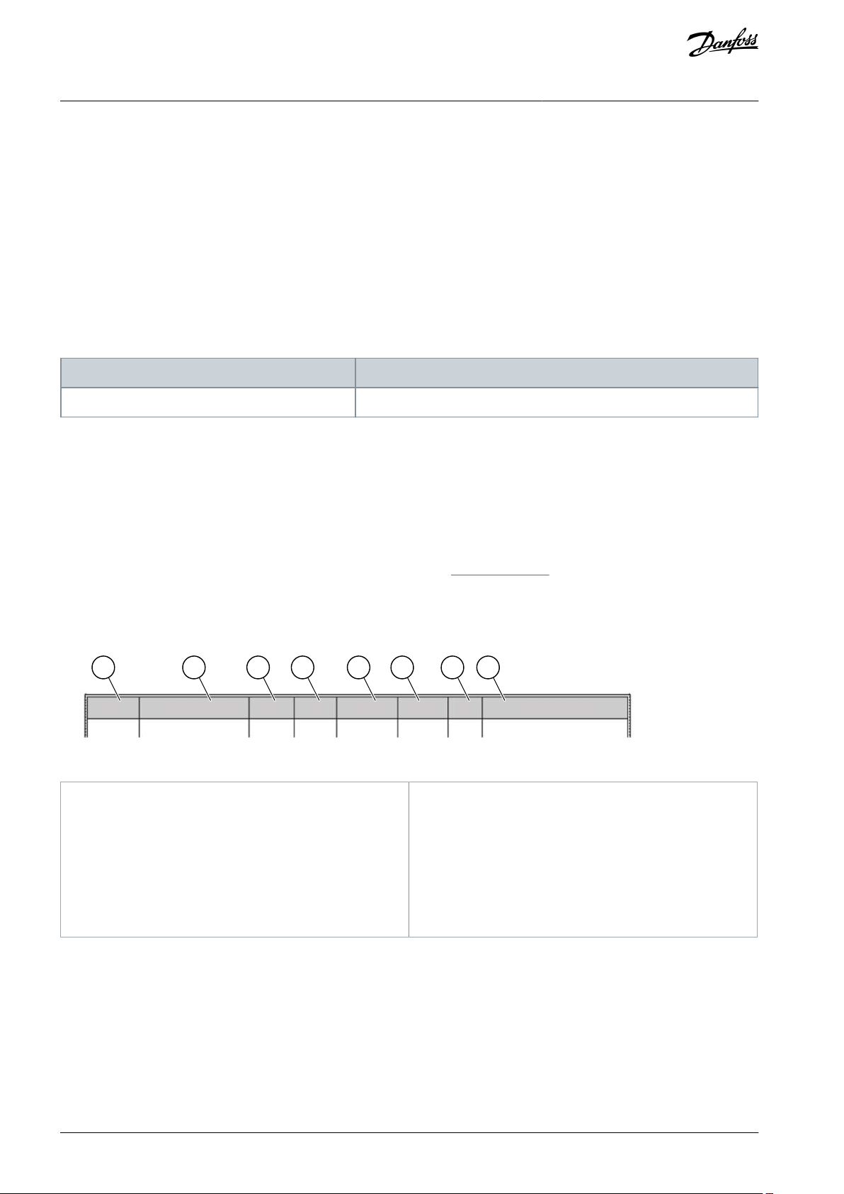
A
The location of the parameter in the menu, that is,
the parameter number.
B
The name of the parameter.
C
The minimum value of the parameter.
D
The maximum value of the parameter.
E
The unit of the value of the parameter. The unit
shows if it is available.
F
The value that was set in the factory.
G
The ID number of the parameter.
H
A short description of the values of the parameter
and/or its function.
VACON® 3000
Application Guide
Introduction
1 Introduction
1.1 Purpose of this Application Guide
This Application Guide provides information for configuring the system, controlling the AC drive, accessing parameters, programming, and troubleshooting of the AC drive. It is intended for use by qualified personnel. Read and follow the instructions to use the
drive safely and professionally. Pay particular attention to the safety instructions and general warnings that are provided in this
manual and other documentation delivered with the drive.
1.2 Manual and Software Version
This manual is regularly reviewed and updated. All suggestions for improvement are welcome.
The original language of this manual is English.
Table 1: Manual and Software Version
1.3 Additional Resources
Other resources are available to understand advanced AC drive functions and operation.
•
The VACON® 3000 Design Guide provides technical information to understand the capabilities of the VACON® 3000 Drive Kit for
integration into motor control and monitoring systems.
•
The VACON® 3000 Operating Guides provide detailed information for the installation, commissioning, and start-up of the drive.
•
The operating and installation guides for VACON® options give detailed information about specific drive options.
Supplementary publications and manuals are available from Danfoss. See www.danfoss.com for listings.
1.4 Parameter Table Reading Guide
This manual includes a large quantity of parameter tables. These instructions tell you how to read the tables.
Illustration 1: Parameter Table Reading Guide
1.5 Start-up Quick Guide
The start-up wizard makes the commissioning of the drive easy and reduces the manual work with the parameters. It is also possible
to edit these parameters later.
1.5.1 Start-Up Wizard for INU
The start-up wizard tells you to give necessary data for the drive to control your procedure.
Procedure
AB319735759636en-000101 / DPD0182210 | Danfoss A/S © 2021.09

VACON® 3000
Application Guide
1.
Select language (P6.1).
If a battery is installed, the steps 2–5 are shown.
2.
Set daylight saving time (P5.5.5). (Russia, US, EU, or OFF)
3.
Set time (P5.5.2).
4.
Set year (P5.5.4).
5.
Set date (P5.5.3).
6.
Run start-up wizard?
If the selection is No, the start-up wizard ends.
7.
Set a value for P3.1.2.2 Motor Type (so that it agrees with the nameplate).
8.
Set a value for P3.1.1.1 Motor Nominal Voltage (so that it agrees with the nameplate).
9.
Set a value for P3.1.1.2 Motor Nominal Frequency (so that it agrees with the nameplate).
10.
Set a value for P3.1.1.3 Motor Nominal Speed (so that it agrees with the nameplate).
11.
Set a value for P3.1.1.4 Motor Nominal Current.
12.
Set a value for P3.1.1.5 Motor Cos Phi.
13.
Set a value for P3.3.1.1 Minimum Frequency Reference.
14.
Set a value for P3.3.1.2 Maximum Frequency Reference.
15.
Set a value for P3.4.1.2 Acceleration Time 1.
16.
Set a value for P3.4.1.3 Deceleration Time 1.
After these selections, the start-up wizard is completed. To start the start-up wizard again, go to the parameter B6.5.1 Restore Factory Defaults.
Introduction
1.5.2 Start-Up Wizard for AFE
The start-up wizard tells you to give necessary data for the drive to control your procedure.
Procedure
1.
Select language (P6.1).
If a battery is installed, the steps 2–5 are shown.
2.
Set daylight saving time (P5.5.5). (Russia, US, EU, or OFF)
3.
Set time (P5.5.2).
4.
Set year (P5.5.4).
5.
Set date (P5.5.3).
After these selections, the start-up wizard is completed. To start the start-up wizard again, go to the parameter B6.5.1 Restore Factory Defaults.
AB319735759636en-000101 / DPD01822 | 11Danfoss A/S © 2021.09
e30bu012
A
B C
I
H D
G
F E
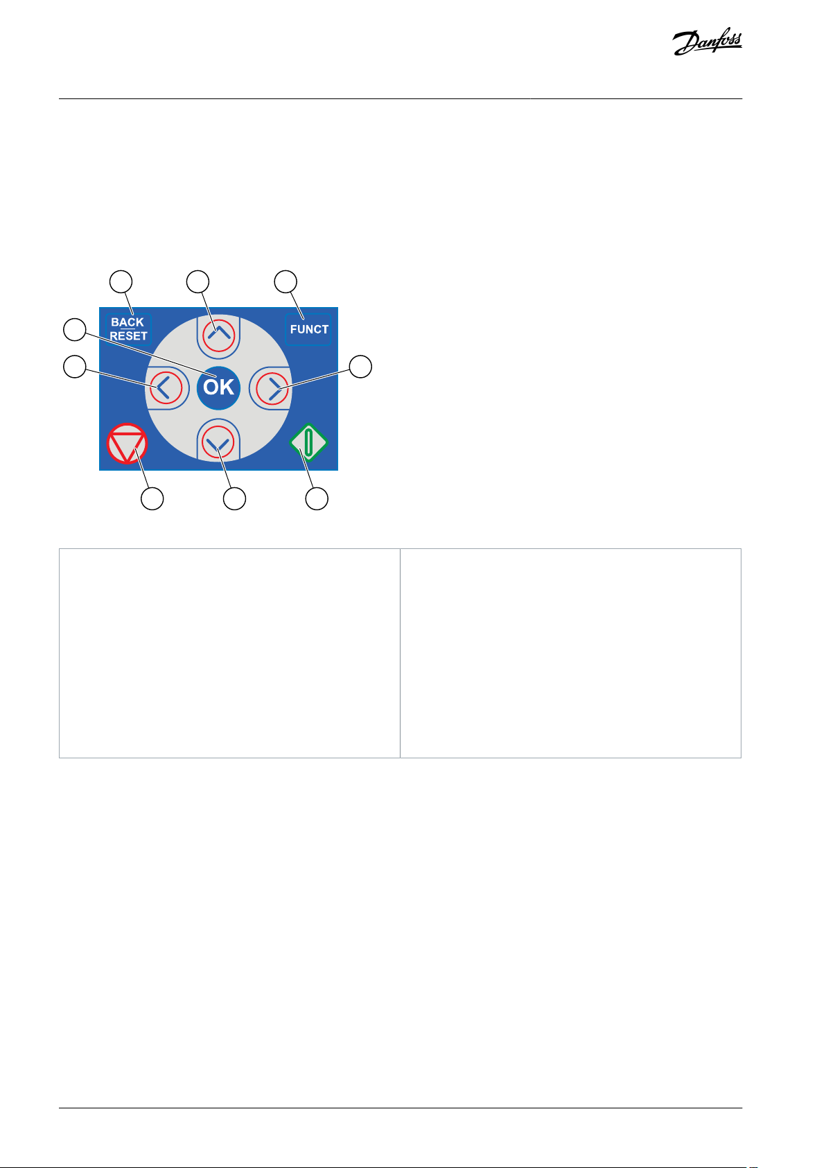
A
The [BACK/RESET] button. Use it to move back in the
menu, exit the Edit mode, reset a fault.
B
The arrow button UP. Use it to scroll up the menu
and to increase a value.
C
The [FUNCT] button. Use it to change the rotation
direction of the motor, access the control page, and
change the control place.
D
The arrow button RIGHT.
E
The START button.
F
The arrow button DOWN. Use it to scroll the menu
down and to decrease a value.
G
The STOP button.
H
The arrow button LEFT. Use it to move the cursor
left.
I
The [OK] button. Use it to go into an active level or
item, or to accept a selection.
VACON® 3000
Application Guide
User Interfaces
2 User Interfaces
2.1 Description of the Control Panel
2.1.1 Control Panel and the Keypad
The control panel is the interface between the AC drive and the user. With the control panel, you can control the speed of a motor
and monitor the status of the AC drive. You can also set the parameters of the AC drive.
Illustration 2: Buttons of the Keypad
2.1.2 Displays of the Control Panel
The display shows this data.
•
The status of the motor and the drive.
•
Faults in the motor and in the drive.
•
Your location in the menu structure.
If the text in the text display is too long for the display, the text scrolls to show the full text string. Some functions are only available
in the graphical display.
AB319735759636en-000101 / DPD0182212 | Danfoss A/S © 2021.09
STOP
READY
I/O
Main Menu
A
B C D E
F
H
G
Quick Setup
( 17 )
Monitor
( 5 )
Parameters
( 12 )
M1ID:
e30bu013.10
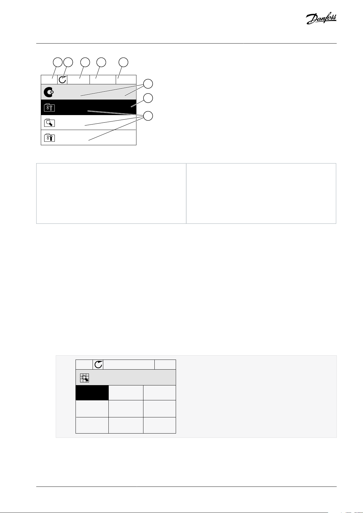
A
The first status field: STOP/RUN
B
The rotation direction of the motor
C
The second status field: READY/NOT READY/FAULT
D
The alarm field: ALARM/-
E
The control place field: PC/I/O/KEYPAD/ FIELDBUS
F
The location field: the ID number of the parameter
and the current location in the menu
G
An activated group or item
H
The number of items in the group in question
STOP
READY I/O
ID:25
FreqReference
Multimonitor
20.0 Hz
Motor Curre
0.00A
DC-link volt
0.0V
Output Freq
0.00 Hz
Motor Speed
0.0 rpm
Motor Voltage
0.0V
Motor Tempera
0.0%
Motor Torque
0.00 %
Unit Tempera
81.9°C
FreqReference
e30bg686.10
VACON® 3000
Application Guide
Illustration 3: Graphical Display of the Control Panel
User Interfaces
2.2 Graphical Display
2.2.1 Uses of the Monitor Menu
Monitor Menu allows monitoring the actual values of the parameters and signals. It also allows monitoring the statuses and measurements. Some of the values to be monitored can be customized.
2.2.2 Multimonitor Monitoring
2.2.2.1 Changing the Items to Monitor
On the Multimonitor page, 4–9 items can be monitored. Select the number of items with the parameter Multimonitor View (ID 1196)
in the Application Settings menu.
Procedure
1.
Go into the Monitor menu with the [OK] button.
2.
Go into Multimonitor.
To replace an old item, activate it. Use the arrow buttons.
3.
AB319735759636en-000101 / DPD01822 | 13Danfoss A/S © 2021.09
STOP
READY I/O
ID:1 M2.1.1.1
FreqReference
0.00 %
Motor Power
Output frequency
FreqReference
Motor Speed
Motor Current
Motor Torque
0.00 Hz
10.00 Hz
0.00 rpm
0.00 A
0.00 %
e30bg687.10
STOP
READY
I/O
Rem Control Place
M3.2.1
ID:
Edit
Help
Add to favourites
e30bu017.10
STOP
READY
I/O
Rem Control Place
M3.2.1ID:
FieldbusCTRL
I/O Control
e30bu018.10
VACON® 3000
Application Guide
4.
To select a new item in the list, push [OK].
2.2.3 Editing the Text Values
This topic gives instructions on how to edit the text values on the graphical display.
Procedure
1.
Find the parameter with the arrow buttons.
2.
To go to the Edit mode, push the [OK] button 2 times or push the arrow button Right.
User Interfaces
3.
To set a new value, push the arrow buttons Up and Down.
4.
To accept the change, push the [OK] button. To ignore the change, use the [BACK/RESET] button.
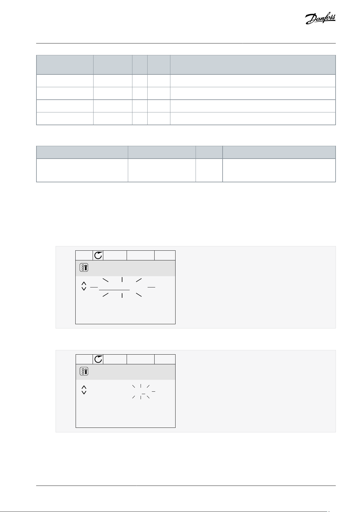
2.2.4 Editing the Numerical Values
This topic gives instructions on how to edit the numerical values on the graphical display.
Procedure
1.
Find the parameter with the arrow buttons.
2.
To go to the Edit mode, push the [OK] button 2 times or push the arrow button Right.
AB319735759636en-000101 / DPD0182214 | Danfoss A/S © 2021.09
STOP
READY
I/O
MinFreqReference
P3.3.1.1
ID:101
0.00 Hz
Min: 0.00Hz
Max: 50.00Hz
e30bu020.10
STOP
READY
I/O
P3.12.1.3ID:1466
Interval 1
00:00:00
00:00:00
ON Time
OFF Time
Days
0
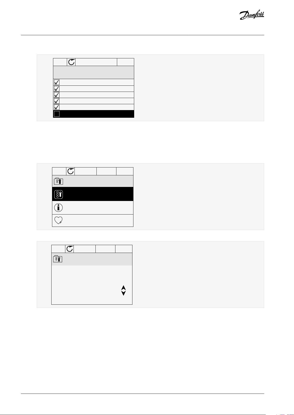
A
e30bu023.10
A
The symbol of the checkbox selection
STOP
READY
I/O
M 3.12.1.3.1
ID:
Days
Monday
Tuesday
Wednesday
Thursday
Friday
Sunday
e30bu025.10
VACON® 3000
Application Guide
3.
Move from digit to digit with the arrow buttons Left and Right. Change the digits with the arrow buttons Up and Down.
4.
To accept the change, push the [OK] button. To ignore the change, use the [BACK/RESET] button.
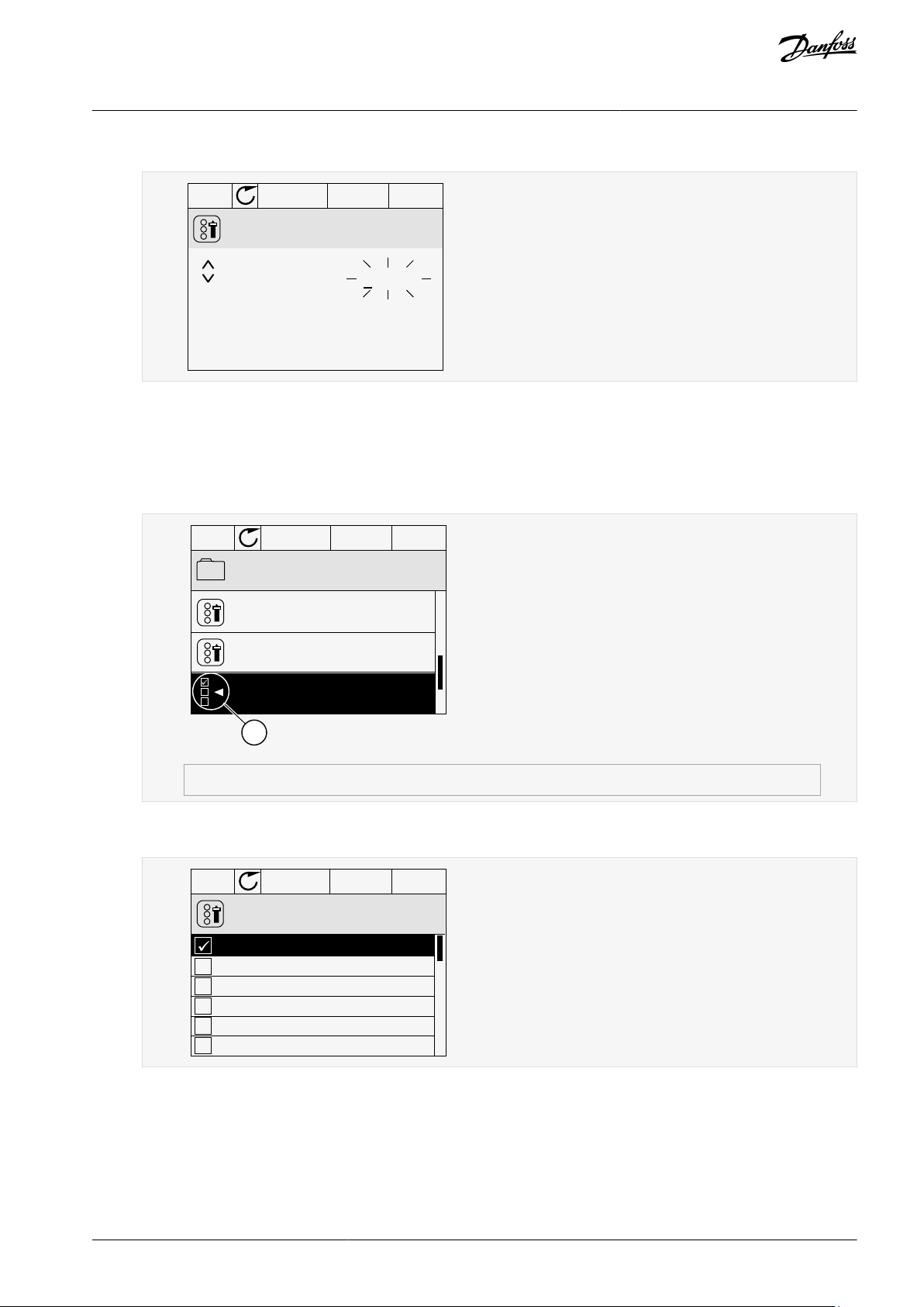
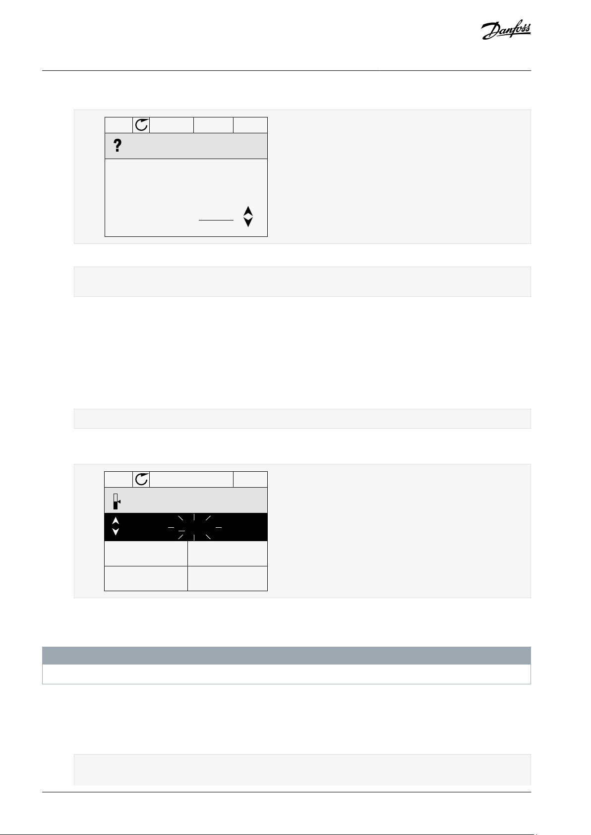
2.2.5 Selecting More than 1 Value
With some parameters, more than 1 value can be selected. Select a checkbox at each necessary value.
Procedure
1.
Find the parameter. There is a symbol on the display when a checkbox selection is possible.
User Interfaces
2.
To move in the list of values, use the arrow buttons Up and Down.
3.
To add a value into your selection, select the box that is next to it with the arrow button Right.
2.2.6 Faults
2.2.6.1 Uses of the Active Faults Submenu
When there is a fault or many faults, the display shows the name of the fault and blinks. Push [OK] to go back to the Diagnostics
menu. The submenu Active faults shows the number of faults. To see the fault-time data, select a fault and push [OK].
The Active faults submenu can keep storage of maximum 10 faults. The submenu shows the faults in the sequence in which they
occurred.
AB319735759636en-000101 / DPD01822 | 15Danfoss A/S © 2021.09
STOP
READY I/O
ID: M4.2
Reset faults
Help
Reset faults
e30bg663.10
Active faults
( 0 )
( 39 )
STOP
READY I/O
Diagnostics
M4.1ID:
Reset faults
Fault history
e30bg665.10
VACON® 3000
Application Guide
User Interfaces
2.2.6.2 Reset Faults
When the drive shows a fault and stops, examine the cause of fault, and reset the fault. The fault stays active until it is reset.
There are 2 procedures to reset a fault in the local control place: with the [BACK/RESET] button and with a parameter. It is also possi-
ble to reset faults by using I/O, a fieldbus, or a PC tool.
N O T I C E
Before resetting the fault, remove the external control signal to prevent restarting the drive accidentally.
2.2.6.2.1 Resetting Faults with the [BACK/RESET] Button
Procedure
1.
Push the [BACK/RESET] button on the keypad of the control panel for 2 seconds.
2.2.6.2.2 Resetting Faults with a Parameter on the Graphical Display
Faults can be reset with the parameter Reset Faults.
Procedure
1.
Go to the Diagnostics Menu.
2.
Go to the submenu Reset faults.
Select the parameter Reset Faults.
3.
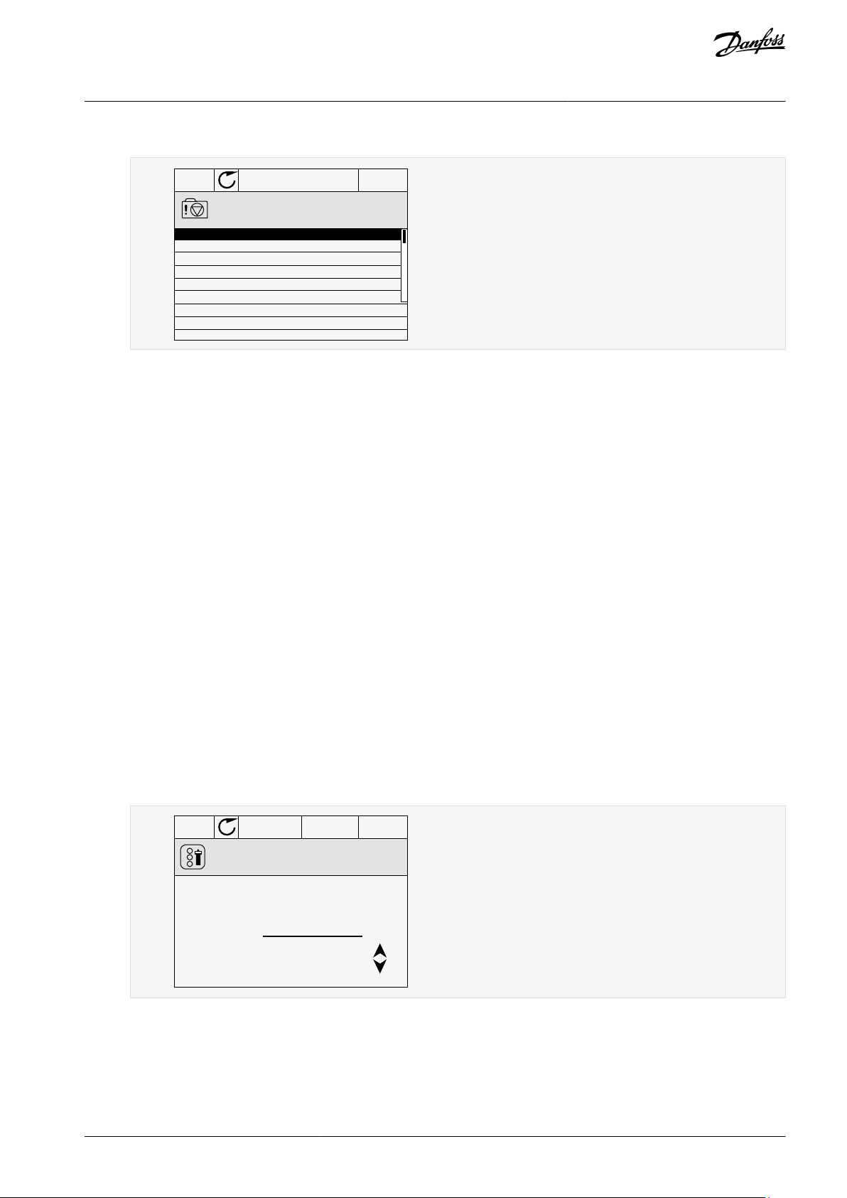
2.2.6.3 Uses of the Fault History
The Fault history shows more data on the faults. There is a maximum number of 40 faults in the Fault history.
2.2.6.3.1 Examining the Fault History on the Graphical Display
Procedure
1.
To see more data on a fault, go to Fault history.
2.
To examine the data of a fault, push the Arrow button Right.
AB319735759636en-000101 / DPD0182216 | Danfoss A/S © 2021.09
STOP
READY
I/O
Code 39
Source 3
Source 1
ID
380
State
Info old
Date
7.12.2009
Time
04:46:33
Operating time
862537s
Source 2
Fault history
M4.3.3.2ID:
e30bg666.10
STOP
READY Keypad
ID:1805
Choose action
Control page
Change direction
Local/Remote
e30bu027.10
VACON® 3000
Application Guide
3.
Examine the data in a list.
2.2.7 [FUNCT] Button
The [FUNCT] button can be used for 4 functions.
•
To have access to the Control page.
•
To change easily between the Local and Remote control places.
•
To change the rotation direction.
•
To edit quickly a parameter value.
User Interfaces
2.2.7.1 Different Control Places
The selection of the control place determines from where the AC drive takes the start and stop commands. All the control places
have a parameter for the selection of the frequency reference source. The Local control place is always Keypad. The Remote control
place is I/O or Fieldbus. The status bar of the display shows the current control place.
It is possible to use I/O A, I/O B, and Fieldbus as Remote control places. I/O A and Fieldbus have the lowest priority. Select them with
P3.2.1 (Remote Control Place). I/O B can bypass the Remote control places I/O A and Fieldbus with a digital input. Select the digital
input with parameter P3.5.1.7 (I/O B Control Force).
Keypad is always used as a control place when the control place is Local. Local control has higher priority than Remote control. For
example, if parameter P3.5.1.7 bypasses the control place with a digital input, and Local is selected in Remote control, Keypad becomes the control place. Use the [FUNCT] button or P3.2.2 Local/Remote to change between the Local and Remote control.
2.2.7.2 Changing the Control Place
This topic gives instructions on how to change the control place on the control panel.
Procedure
Anywhere in the menu structure, push the [FUNCT] button.
1.
To select Local/Remote, use the arrow buttons Up and Down. Push the [OK] button.
2.
AB319735759636en-000101 / DPD01822 | 17Danfoss A/S © 2021.09
STOP
READY Keypad
ID:211
Local/Remote
Remote
Local
e30bu028.10
STOP
READY Keypad
ID: 168
Keypad Reference
0.00Hz
Output Frequency
Motor Current
Motor Torque
Motor Power
0.00Hz
0.00A
0.00%
0.00%
e30bg671.10
VACON® 3000
Application Guide
3.
To select Local or Remote, use the arrow buttons Up and Down again. To accept the selection, push the [OK] button.
User Interfaces
4.
If Remote control place is changed to Local, that is, Keypad, give a keypad reference.
After the selection, the display goes back into the same location where it was when the [FUNCT] button was push-
ed.
2.2.7.3 Going into the Control Page
It is easy to monitor the most important values in the Control page.
If other control places or reference values are used, the display shows the frequency reference, which cannot be edited. The other
values on the page are Multimonitor values. These monitoring values can be selected.
Procedure
Anywhere in the menu structure, push the [FUNCT] button.
1.
2.
To select the Control page, push the arrow buttons Up and Down. Go in with the [OK] button.
The Control page opens.
With the Local control place and the keypad reference selected, P3.3.1.8 Keypad Reference can be set with the [OK] button.
3.
To change the digits in the value, push the arrow buttons Up and Down. Accept the change with the [OK] button.
4.
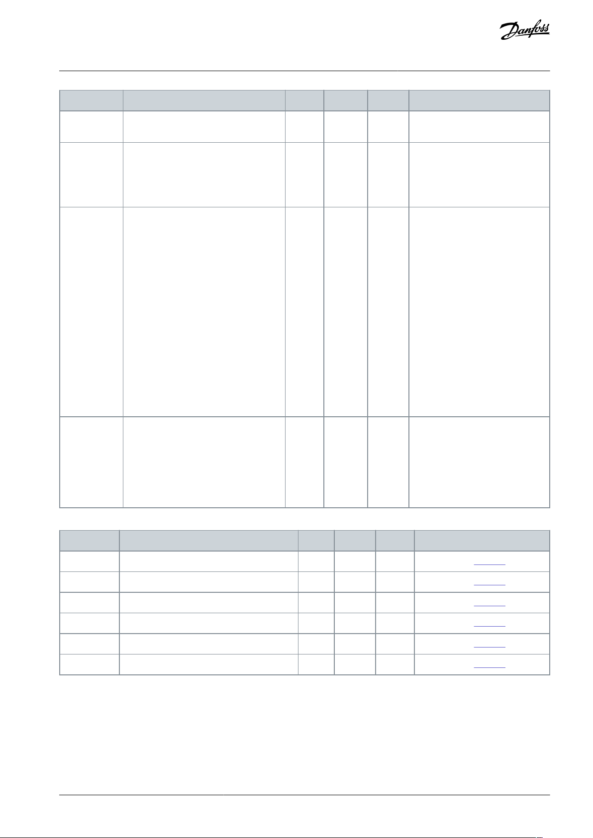
2.2.7.4 Changing the Rotation Direction
The rotation direction of the motor can be changed quickly with the [FUNCT] button.
N O T I C E
The command Change direction is available in the menu only if the current control place is Local.
Procedure
1.
Anywhere in the menu structure, push the [FUNCT] button.
2.
To select Change direction, push the arrow buttons Up and Down. Push the [OK] button.
3.
Select a new rotation direction.
The current rotation direction blinks.
AB319735759636en-000101 / DPD0182218 | Danfoss A/S © 2021.09
RUN
READY Keypad
ID:1805
Choose action
Forward
Reverse
e30bg672.10
STOP
READY I/O
ID:
M1
Main Menu
Monitor
( 7 )
Parameters
( 15 )
Diagnostics
( 6 )
e30bg673.10
VACON® 3000
Application Guide
4.
Push the [OK] button.
The rotation direction changes immediately. The arrow indication in the status field of the display changes.
User Interfaces
2.2.7.5 Using the Quick Edit Function
With the Quick Edit function, a parameter can be accessed quickly by typing the ID number of the parameter.
Procedure
1.
Anywhere in the menu structure, push the [FUNCT] button.
2.
Push the arrow buttons Up and Down to select Quick Edit and accept with the [OK] button.
Write the ID number of a parameter or monitoring value. Push [OK].
3.
The display shows the parameter value in the edit mode and the monitoring value in the monitoring mode.
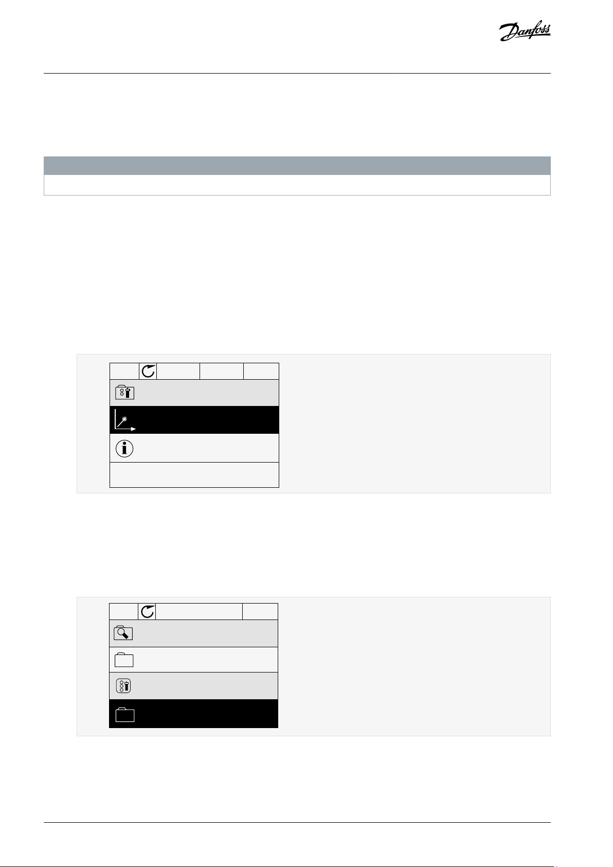
2.2.8 Copying the Parameters of an AC Drive
Use this function to copy parameters from a drive to another. Before downloading parameters from the control panel to the drive,
stop the drive.
N O T I C E
This function is available only in the graphical display.
Procedure
1.
Save the parameters to the control panel.
a.
Go into the User settings menu.
AB319735759636en-000101 / DPD01822 | 19Danfoss A/S © 2021.09
STOP
READY Keypad
ID: M6.5
User settings
Language selection
English
Parameter backup
( 7 )
Drive name
Drive
e30bg674.10
STOP
READY Keypad
ID: M6.5.1
Parameter backup
Restore factory defaults
Save to keypad
Restore from keypad
e30bg675.10
VACON® 3000
Application Guide
b.
Go into the Parameter backup submenu.
c.
Use the arrow buttons Up and Down to select a function. Accept the selection with the [OK] button.
User Interfaces
The command Restore factory defaults brings back the parameter settings that were made at the factory. Use the command Save to keypad to copy all the parameters to the control panel. The command Restore from keypad copies all the
parameters from the control panel to the drive.
2.
Detach the control panel and connect it to another drive.
3.
Download the parameters to the new drive with the command Restore from keypad.
2.2.9 Comparing the Parameters
Use this function to compare the current parameter set with one of these 4 sets. See more about these parameters in 4.8.2 Parame-
ter Backup Parameters.
•
Set 1 (B6.5.4 Save to Set 1)
•
Set 2 (B6.5.6 Save to Set 2)
•
Defaults (B6.5.1 Restore Factory Defaults)
N O T I C E
If you have not saved the parameter set with which you want to compare the current set, the display shows the text Comparing
failed.
Procedure
1.
Go into the User settings menu.
AB319735759636en-000101 / DPD0182220 | Danfoss A/S © 2021.09
STOP
READY I/O
ID: M6.6
User Settings
Language Selection
Parameter Backup
Parameter Compare
English
(4)
(7)
e30bg676.10
STOP
READY I/O
ID:
B6.6.1
Parameter Compare
Active set-Set 1
Active set-Set 2
Active set-Defaults
e30bg677.10
STOP
READY I/O
ID:113
Active set-Set 1
Motor Nom Currnt
Motor Cos Phi
0.56A
1.90A
0.68
1.74
A B C D
e30bg678.10
A
The current value
B
The value of the other set
C
The current value
D
The value of the other set
VACON® 3000
Application Guide
2.
Go into the Parameter Compare function.
3.
Select the pair of sets. Push [OK] to accept the selection.
User Interfaces
4.
5.
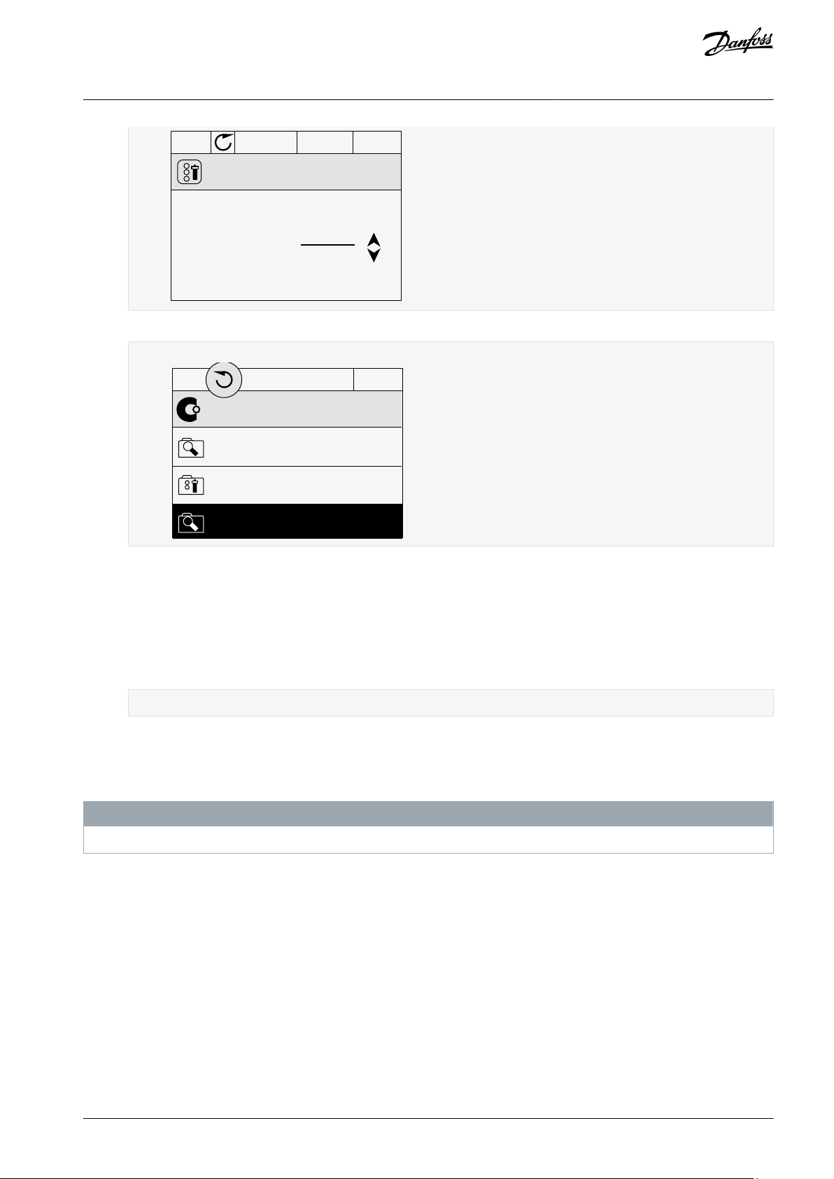
2.2.10 Reading Help Texts
The graphical display can show help texts on many topics. All the parameters have a help text. The help texts are also available for
the faults, alarms, and the start-up wizard.
The help texts are always in English.
Procedure
1.
Select Active and push [OK].
Examine the comparing between the current values and the values of the other set.
N O T I C E
Find the item to read.
AB319735759636en-000101 / DPD01822 | 21Danfoss A/S © 2021.09

STOP
READY I/O
ID:403 M3.5.1.1
Ctrl signal 1 A
Edit
Help
Add to favourites
e30bg679.10
STOP
READY
I/O
Motor Nom Freq
Edit
Help
Add to favourites
e30bg659.10
VACON® 3000
Application Guide
2.
Use the arrow buttons Up and Down to select Help.
User Interfaces
3.
To open the help text, push the [OK] button.
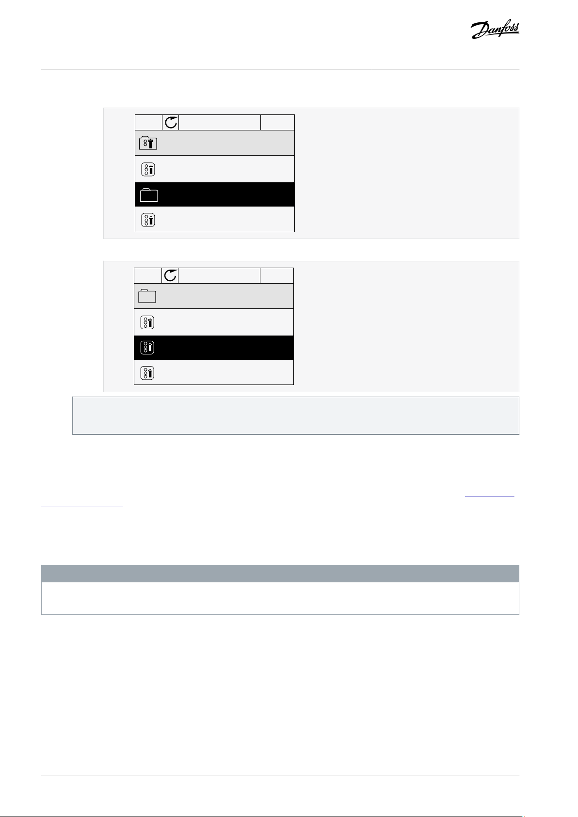
2.2.11 Using the Favourites Menu
This menu is not available in the VACON® Live tool.
If the same items are used frequently, they can be added into Favourites. You can collect a set of parameters or monitoring signals
from all the control panel menus. It is not necessary to find them in the menu structure one by one. As an alternative, add them into
the Favourites folder where it is easy to find them.
2.2.11.1 Adding an Item to the Favourites
It is possible to add frequently used items into Favourites where they are easily accessible.
Procedure
1.
Find the item to be added to Favourites. Push the [OK] button.
2.
Select Add to favourites and push the [OK] button.
The steps are now completed.
3.
To continue, read the instructions on the display.
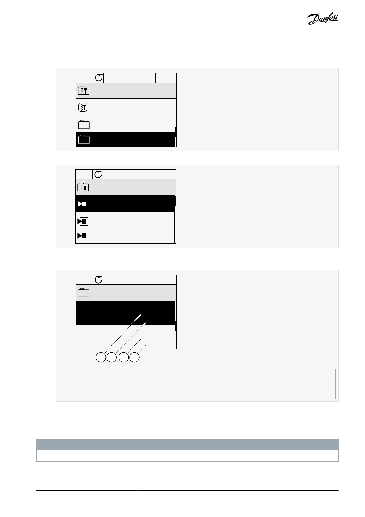
2.2.11.2 Removing an Item from the Favourites
Procedure
1.
Go to the Favourites.
2.
Find the item to be removed. Push the [OK] button.
AB319735759636en-000101 / DPD0182222 | Danfoss A/S © 2021.09
STOP
READY
I/O
Motor Nom Freq
Rem from favourites
Help
Monitor
e30bg660.10
e30bg685.10
VACON® 3000
Application Guide
3.
Select Rem from favourites.
User Interfaces
4.
To remove the item, push the [OK] button again.
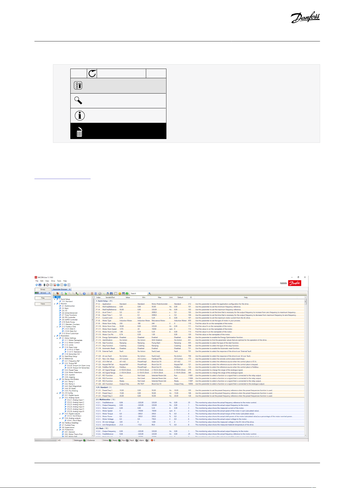
2.3 VACON® Live PC Tool
VACON® Live is a PC tool for commissioning and maintenance of the VACON® AC drives. VACON® Live can be downloaded from
https://www.danfoss.com.
The VACON® Live PC tool includes these functions.
•
Parameterization, monitoring, drive info, data logger, and so on.
•
The software download tool VACON® Loader
Serial communication and Ethernet support
•
Windows XP, Vista, 7, 8, and 10 support
•
17 languages: English, German, Spanish, Finnish, French, Italian, Russian, Swedish, Chinese, Czech, Danish, Dutch, Polish, Portu-
•
guese, Romanian, Slovak and Turkish
Make the connection between the AC drive and the PC tool with the VACON® serial communication cable. The serial communication drivers are installed automatically during the installation of VACON® Live. After the cable is installed, VACON® Live finds the
connected drive automatically.
See more on how to use VACON® Live in the help menu of the program.
Illustration 4: The VACON® Live PC Tool
AB319735759636en-000101 / DPD01822 | 23Danfoss A/S © 2021.09
21
3
4
5
6
7
8
9
10
11
12
13
14
15
16
17
18
19
30
A
B
21
22
23
24
25
26
33
34
Slot A
Slot B
C
A
B
D
E
A.1
G
F
A.2 A.1
A.2 A.3 A.4 A.5 A.6
e30bg493.10
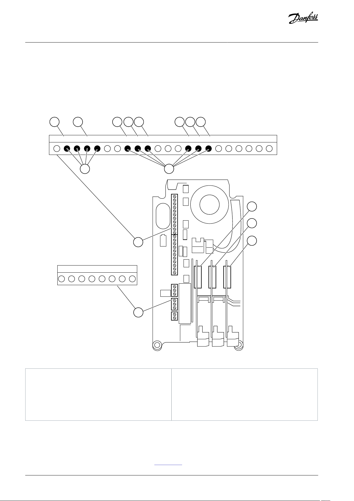
A
Standard board slot A and its terminals
B
Standard board slot B and its terminals
C
Option board slot C
D
Option board slot D
E
Option board slot E
F
Programmable digital inputs (DI)
G
Programmable analog inputs (AI)
VACON® 3000
Programming of Digital and
Application Guide
Analog Inputs
3 Programming of Digital and Analog Inputs
3.1 General Information on the Programming
The programming of inputs of the AC drive is flexible. It is possible to use freely the available inputs of the standard and optional I/O
for different functions.
It is possible to expand the available capacity of I/O with option boards. It is possible to install the option boards in the slots C, D,
and E. For more data on the installation of option boards, see the Installation Guide.
Illustration 5: The Option Board Slots and Programmable Inputs
3.2 DIP Switches on the Control Unit
3.2.1 Selection of Terminal Functions with DIP Switches
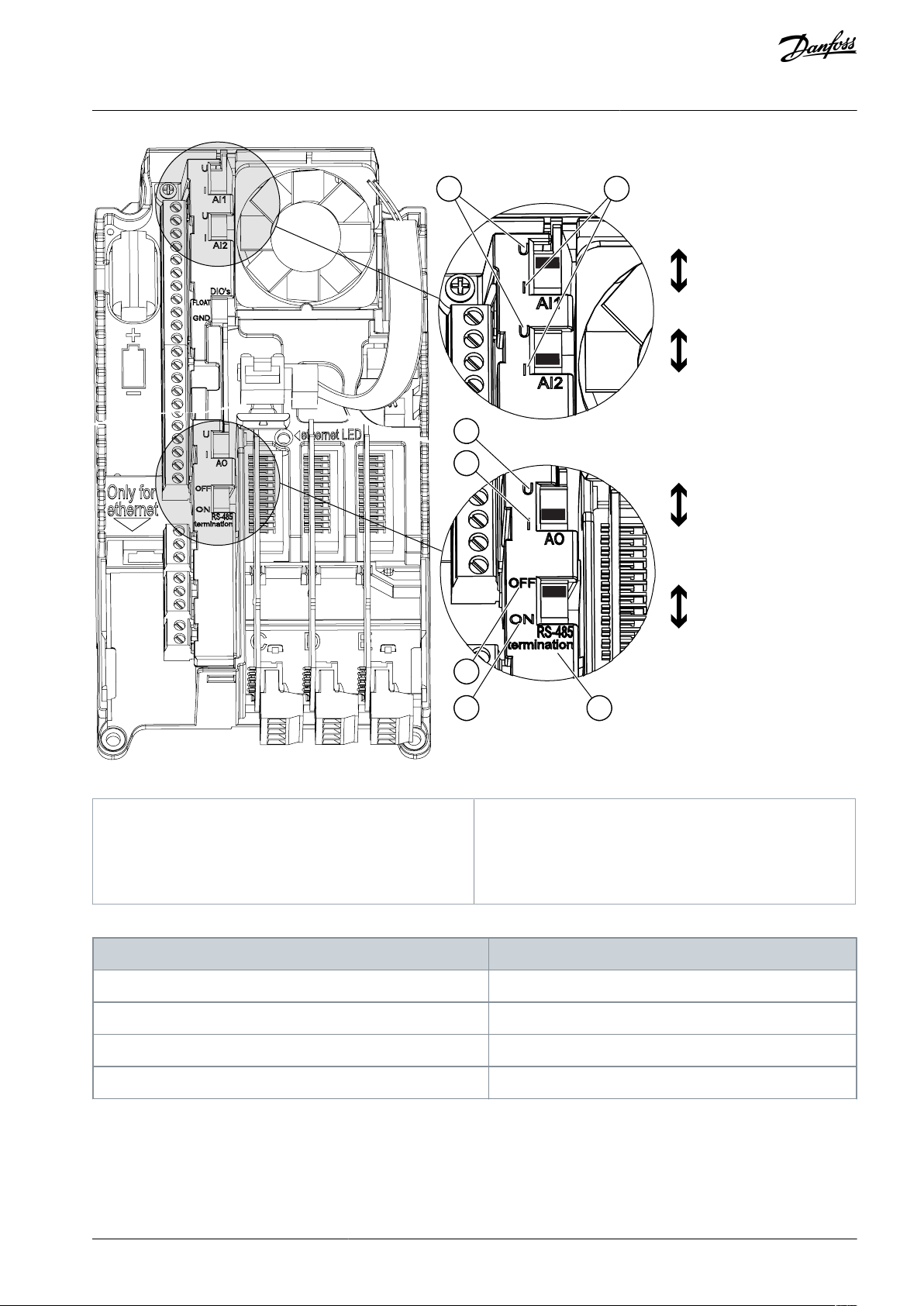
Two selections for specified terminals can be done with the DIP switches. The switches have two positions: up and down. See the
location of the DIP switches and the possible selections in Illustration 6.
AB319735759636en-000101 / DPD0182224 | Danfoss A/S © 2021.09
A B
A
B
C
D
E
AI1
U
I
AO1
U
I
RS485
OFF
ON
AI2
U
I
e30bg737.10
A
The voltage signal (U), 0–10 V input
B
The current signal (I), 0–20 mA input
C
OFFDONEThe RS485 bus termination
The DIP switch
The default position
AI1UAI2IAO1IRS485 bus termination
OFF
VACON® 3000
Application Guide
Programming of Digital and
Analog Inputs
Illustration 6: The Selections of the DIP Switches
Table 2: The Default Positions of the DIP Switches
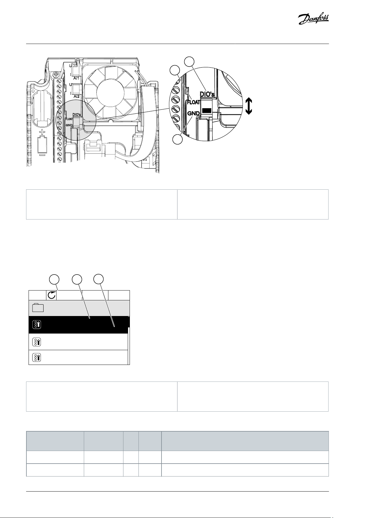
3.2.2 Isolation of the Digital Inputs from Ground
It is possible to isolate from ground the digital inputs (terminals 8–10 and 14–16) on the standard I/O board. To do this, change the
position of a DIP switch on the control board.
AB319735759636en-000101 / DPD01822 | 25Danfoss A/S © 2021.09
A
B
C
e30bg738.10
A
The digital inputs
B
Floating
C
Connected to ground (default)
STOP
READY
I/O
ID:405
P3.5.1.11
Digital Inputs
BA
C
DigINSlotA.3
DigINSlot0.2
DigINSlotA.6
Fault Reset Close
Ext Fault Open
Ext Fault Close
e30bg692.10
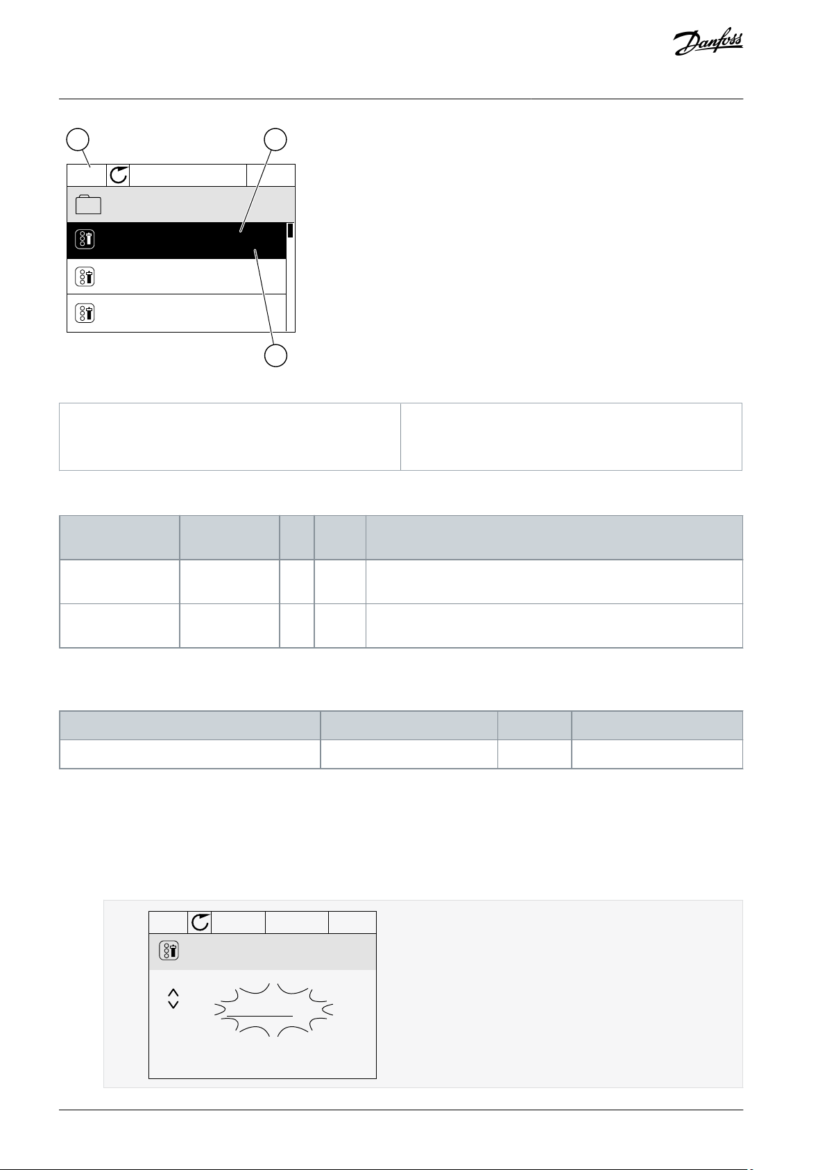
A
The graphical display
B
The name of the parameter, that is, the function
C
The value of the parameter, that is, the set digital input
Input type (graphical
display)
Input type
(text display)
Slot
Input #
Explanation
DigIN
dIA1
Digital input #1 (terminal 8) on a board in Slot A (standard I/O board).
DigIN
dIA2
Digital input #2 (terminal 9) on a board in Slot A (standard I/O board).
VACON® 3000
Application Guide
Illustration 7: Change the Position of This Switch to Isolate the Digital Inputs from Ground
Programming of Digital and
Analog Inputs
3.3 Programming of Digital Inputs
The digital input parameters are functions that you can connect to a digital input terminal. The text DigIn Slot A.2 means the second
input on the slot A. It is also possible to connect the functions to time channels. The time channels work as terminals.
You can monitor the statuses of the digital inputs and the digital outputs in the Multimonitoring view.
To give a digital input to a function, set a value to the correct parameter.
Illustration 8: The Digital inputs menu in the graphical display
Example
In the standard I/O board compilation, there are 6 digital inputs available: the slot A terminals 8, 9, 10, 14, 15 and 16.
AB319735759636en-000101 / DPD0182226 | Danfoss A/S © 2021.09
Input type (graphical
display)
Input type
(text display)
Slot
Input #
Explanation
DigIN
dIA3
Digital input #3 (terminal 10) on a board in Slot A (standard I/O board).
DigIN
dIA4
Digital input #4 (terminal 14) on a board in Slot A (standard I/O board).
DigIN
dIA5
Digital input #5 (terminal 15) on a board in Slot A (standard I/O board).
DigIN
dIA6
Digital input #6 (terminal 16) on a board in Slot A (standard I/O board).
Parameter
Default
ID
Description
External fault close
DigIN SlotA.3
405
OPEN = OK
CLOSED = External fault
STOP
READY I/O
Ext Fault Close
P3.5.1.11
ID:405
Min:
Max:
DigIN SlotA .3
e30bg705.10
STOP
READY I/O
Ext Fault Close
P3.5.1.11
ID:405
Min:
Max:
DigIN SlotA. 6
e30bg706.10
VACON® 3000
Programming of Digital and
Application Guide
The function External Fault Close (ID 405) gets the default value DigIN SlotA.3 in the graphical display, and dI A.3 in the text display.
After this selection, a digital signal to the digital input DI3 (terminal 10) controls External Fault Close.
To change the input from DI3 to, for example, DI6 (terminal 16) on the standard I/O, obey these instructions.
Analog Inputs
3.3.1 Programming of Digital Inputs in the Graphical Display
Procedure
1.
Select a parameter. To go into the Edit mode, push the arrow button Right.
2.
In the Edit mode, the slot value DigIN SlotA is underlined and blinks. If there are more digital inputs available in the I/O, for
example, because of option boards in slots C, D, or E, select them.
3.
To activate the terminal 3, push the arrow button Right again.
4.
To change the terminal to 6, push the arrow button Up 3 times. Accept the change with the [OK] button.
5.
3.4 Programming of Analog Inputs
You can select the target input for the signal of the analog frequency reference from the available analog inputs.
If the digital input DI6 was already used for some other function, a message shows on the display. Change one of these
selections.
AB319735759636en-000101 / DPD01822 | 27Danfoss A/S © 2021.09
STOP
READY I/O
ID:377 P3.5.2.1.1
Analog Input 1
AI1 Signal Sel
AI1 Filter Time
AnINSlotA.1
0.10s
0-10V/0-20mA
AIl Signal Range
A B
C
e30bg709.10
A
The graphical display
B
The name of the parameter
C
The value of the parameter, that is, the set analog input
Input type (graphical display)
Input type (text
display)
Slot
Input #
Explanation
AnINAIA1Analog input #1 (terminals 2/3) on a board in Slot A (standard I/O
board).
AnINAIA2Analog input #2 (terminals 4/5) on a board in Slot A (standard I/O
board).
Parameter
Default
ID
Description
AI1 Signal Selection
AnIN SlotA.1
377
STOP
READY I/O
AI1 Signal Sel
AnIN SlotA .1
P3.5.2.1.1
ID:377
Min:
Max:
e30bg711.10
VACON® 3000
Application Guide
Illustration 9: The Analog inputs menu in the graphical display
Programming of Digital and
Analog Inputs
Example
In the standard I/O board compilation, there are 2 analog inputs available: the slot A terminals 2/3 and 4/5.
AI1 Signal Selection (ID 377) gets the default value AnIN SlotA.1 in the graphical display or AI A.1 in the text display. The target input
for the signal of the analog frequency reference AI1 is then the analog input in the terminals 2/3. Use the dip switches to set the
signal to be voltage or current. See the Installation manual for more data.
To change the input from AI1 to, for example, the analog input on your option board in slot C, obey these instructions.
3.4.1 Programming of Analog Inputs in the Graphical Display
Procedure
1.
To select the parameter, push the arrow button Right.
2.
In the Edit mode, the value AnIN SlotA is underlined and blinks.
AB319735759636en-000101 / DPD0182228 | Danfoss A/S © 2021.09

Source
Function
Slot0.#
Digital inputs:
You can use this function to set a digital signal to be in a constant OPEN or CLOSED state. The manufacturer set
some signals so that they are always in the CLOSED state, for example parameter ID 407 (Run Enable). The Run
Enable signal is always on if you do not change it.
# = 1: Always OPEN
# = 2-10: Always CLOSED
Analog inputs (used for testing purposes):
# = 1: Analog input = 0% of the signal strength
# = 2: Analog input = 20% of the signal strength
# = 3: Analog input = 30% of the signal strength etc.
# = 10: Analog input = 100% of the signal strength
SlotA.#
Number (#) agrees to a digital input in slot A.
SlotB.#
Number (#) agrees to a digital input in slot B.
SlotC.#
Number (#) agrees to a digital input in slot C.
SlotD.#
Number (#) agrees to a digital input in slot D.
SlotE.#
Number (#) agrees to a digital input in slot E.
FieldbusCW.#
Number (#) refers to a control word bit number.
FieldbusPD.#
Number (#) refers to the process data 1 bit number.
Aux 14–Aux 17
Auxiliary I/O signals
MV-star
MV-star signals
Input
Terminal(s)
Reference
Function
Parameter ID
DI18A.1
Control Signal 1 A
403
DI29A.2
Control Signal 2 A
404
DI310A.3
External Fault Close
405
DI414A.4
Preset Frequency Selection 1
419
DI515A.5
Preset Frequency Selection 2
420
DI616A.6
Fault Reset Close
414
AI1
2/3
A.1
AI1 Signal Selection
377
AI2
4/5
A.2
AI2 Signal Selection
388
VACON® 3000
Programming of Digital and
Application Guide
3. To change the value to AnIN SlotC, push the arrow button Up. Accept the change with the [OK] button.
3.5 Descriptions of Signal Sources
Table 3: Descriptions of Signal Sources
Analog Inputs
3.6 Default Functions of Programmable Inputs
Table 4: Default functions of the programmable digital and analog inputs
AB319735759636en-000101 / DPD01822 | 29Danfoss A/S © 2021.09

VACON® 3000
Application Guide
INU Application
4 INU Application
4.1 Overview
The INU application is used to control the INU phase modules of the VACON® 3000.
It is possible to control the drive from the control panel (keypad), Fieldbus, or I/O terminal.
When controlling the drive with the I/O terminal, the frequency reference signal is connected to AI1 (0…10 V) or AI2 (4…20 mA).
The connection depends the type of the signal. There are also 3 preset frequency references available. The preset frequency references can be activated with DI4 and DI5. The start/stop signals of the drive are connected to DI1 (start forward) and DI2 (start reverse).
It is possible to configure all the drive outputs freely. There is 1 analog output (Output Frequency) and 3 relay outputs (Run, Fault,
Ready) available on the Basic I/O board.
AB319735759636en-000101 / DPD0182230 | Danfoss A/S © 2021.09

DI4
DI5
Modbus RTU,
N2, BACnet
1
6
2
3
4
5
18
19
30
12
7
13
8
9
10
14
15
16
21
22
23
11
17
A
B
24
25
26
32
33
mA
FAULT
RUN
RUN
AO1-
+24Vin
24Vout
GND
GND
DI1
DI2
DI3
DI4
DI5
DI6
RO1/1 NC
RO1/2 CM
RO1/3 NO
CM
CM
RS485
RS485
RO2/1 NC
RO2/2 CM
RO2/3 NO
RO3/2 CM
RO3/3 NO
Standard I/O board
Terminal Signal Description
+10Vref
AI1+
AI1-
AI2+
AI2-
24Vout
Reference output
Analog input 1+
Analog input 1-
Analog input 2+
Analog input 2-
24 V auxiliary voltage
I/O ground
Digital input 1
Digital input 2
Digital input 3
Digital input 4
Digital input 5
Digital input 6
Common for DI1-DI6
Common for DI1–DI6
24 V auxiliary voltage
I/O ground
Analog output 1+
Analog output 1-
24 V auxiliary
input voltage
Output
frequency
(0...20 mA)
READY
Serial bus, negative
Serial bus, positive
Relay output 1
Relay output 2
Relay output 3
FAULT
Fault reset
AO1+
Frequency reference
(default 0...10 V)
Frequency reference
(Default 4...20 mA)
Start forward
Start reverse
External fault
Freq. ref.
Open
Closed
Open
Closed
Open
Open
Closed
Closed
Analog input 1
Preset Freq. 1
Preset Freq. 2
Preset Freq. 3
Referencepotentiometer
1...10 kΩ
e30bg736.11
VACON® 3000
Application Guide
INU Application
Illustration 10: The Default Control Connections of the INU Application
4.2 Menu Structure
The data of the AC drive is in menus and submenus. To move between the menus, use the arrow buttons Up and Down in the
keypad. To go into a group or an item, push the [OK] button. To go back to the previous level, push the [BACK/RESET] button.
The display shows the current location in the menu, for example M3.2.1, and the name of the group or item.
AB319735759636en-000101 / DPD01822 | 31Danfoss A/S © 2021.09

Menu
Function
M1 Quick setup
Quick setup
M2 Monitor
Multimonitor
Basic
I/O
Extras/Advanced
PID controller
Fieldbus data
Encoders
Precharge
M3 Parameters
Motor settings
Start/Stop setup
References
Ramps and brakes
I/O Configuration
Fieldbus data mapping
Prohibit frequencies
Supervisions
Protections
Automatic reset
Application settings
PID controller
Motor preheat
Mechanical brake
Encoders
Precharge
M4 Diagnostics
Active faults
Reset faults
Fault history
Total counters
Trip counters
Software info
Drive info
VACON® 3000
Application Guide
Table 5: Menu Structure
INU Application
AB319735759636en-000101 / DPD0182232 | Danfoss A/S © 2021.09

Menu
Function
Unit status
M5 I/O and Hardware
Basic I/O
Slot C
Slot D
Slot E
Real-time clock
Power unit settings
RS485
Ethernet
Fieldbus general
Aux chain
MV-star
M6 User settings
Language selections
Parameter back-up
Parameter compare
Drive name
Licenses
M7 Favorites
Favorites
Index
Parameter
Min
Max
Unit
Default
ID
Description
1.2
Minimum Frequency Reference
0.00
60.00
Hz
0.00
101
1.3
Maximum Frequency Reference
0.00
320.00
Hz
0.00
102
1.4
Acceleration Time 1
0.1
3000.0
s
5.0
103
1.5
Deceleration Time 1
0.1
3000.0
s
5.0
104
1.6
Current Limit
34
420A0
107
1.7
Motor Nominal Voltage
180
4160V0
110
Find this value Un on the nameplate of the motor.
N O T I C E
Find out if the motor connection is Delta or
Star.
VACON® 3000
Application Guide
INU Application
4.3 Quick Setup
Table 6: M1 Quick Setup
AB319735759636en-000101 / DPD01822 | 33Danfoss A/S © 2021.09

Index
Parameter
Min
Max
Unit
Default
ID
Description
1.8
Motor Nominal Frequency
8.00
320.00
Hz
0.00
111
Find this value fn on the nameplate of the motor.
1.9
Motor Nominal Speed
24
19200
RPM0112
Find this value nn on the nameplate of the motor.
1.10
Motor Nominal Current
34
680A0
113
Find this value In on the nameplate of the motor.
1.11
Motor Cos Phi (Power Factor)
0.30
1.00
0.00
120
Find this value on the nameplate of the motor.
1.12
Identification
020
631
0 = No action
1 = At standstill
2 = With rotation
1.13
Start Function
010
505
0 = Ramping
1 = Flying Start
1.14
Stop Function
010
506
0 = Coasting
1 = Ramping
1.15
Automatic Reset
010
731
0 = Disabled
1 = Enabled
1.16
Response to External Fault
032
701
0 = No action
1 = Alarm
2 = Fault (Stop according to stop mode)
3 = Fault (Stop by coasting)
1.17
Response to AI Low Fault
050
700
0 = No action
1 = Alarm
2 = Alarm+preset fault frequency (P3.9.1.1)
3 = Alarm + previous frequency
4 = Fault (Stop according to stop mode)
5 = Fault (Stop by coasting)
1.18
Remote Control Place
010
172
0 = I/O control
1 = Fieldbus control
1.19
I/O Control Reference A
Selection
0106
117
1 = Preset Frequency 0
2 = Keypad Reference
3 = Fieldbus
4 = AI1
5 = AI2
6 = AI1+AI2
7 = PID Reference
8 = Motor Potentiometer
9 = Joystick Reference
10 = Jogging Reference
1.20
Keypad Control Reference
Selection
0102
121
See P1.19.
1.21
Fieldbus Control Reference Selection
0103
122
See P1.19.
VACON® 3000
Application Guide
INU Application
AB319735759636en-000101 / DPD0182234 | Danfoss A/S © 2021.09

Index
Parameter
Min
Max
Unit
Default
ID
Description
1.22
AI1 Signal Range
010
379
0 = 0...10 V/0...20 mA
1 = 2...10 V/4...20 mA
1.23
AI2 Signal Range
011
390
0 = 0...10 V/0...20 mA
1 = 2...10 V/4...20 mA
1.24
RO1 Function
0582
11001
See P3.5.3.2.1
1.25
RO2 Function
0583
11004
See P3.5.3.2.4
1.26
RO3 Function
0581
11007
See P3.5.3.2.7
1.27
AO1 Function
0312
10050
See P3.5.4.1.1
1.28
Preset Frequency 1
0.00
60.00
Hz
10.0
105
1.29
Preset Frequency 2
0.00
60.00
Hz
15.0
106
1.30
Preset Frequency 3
0.00
60.00
Hz
20.0
126
Index
Monitoring value
Unit
Scale
ID
Description
V2.3.1
Output frequency
Hz
0.011V2.3.2
Frequency reference
Hz
0.0125V2.3.3
Motor speed
RPM12
V2.3.4
Motor current
A
Varies
3
V2.3.5
Motor torque
%
0.14V2.3.7
Motor shaft power
%
0.15V2.3.8
Motor shaft power
kW/hp
Varies
73
V2.3.9
Motor voltage
V
0.16V2.3.10
DC-link voltage
V17
V2.3.11
Unit temperature
°C
0.1
8
VACON® 3000
Application Guide
INU Application
4.4 Monitor Menu
4.4.1 Basic Monitoring
4.4.1.1 Uses of the Basic Monitoring
Only the standard I/O board statuses are available in the Monitor menu. For the statuses of all the I/O board signals as raw data, see
the I/O and Hardware menu.
Check the statuses of the expander I/O board in the I/O and Hardware menu when the system asks.
4.4.1.2 Basic Monitoring Parameters
Table 7: Items in the Basic Monitoring Menu
AB319735759636en-000101 / DPD01822 | 35Danfoss A/S © 2021.09

Index
Monitoring value
Unit
Scale
ID
Description
V2.3.12
Motor temperature
%
0.19V2.3.13
Torque reference
%
0.118V2.3.14
Output power
kW179
Index
Monitoring value
Unit
Scale
ID
Description
V2.4.1
Slot A DIN 1, 2, 3
115V2.4.2
Slot A DIN 4, 5, 6
116V2.4.3
Slot B RO 1, 2, 3
117V2.4.4
Analog input 1
%
0.0159Slot A.1 as default.
V2.4.5
Analog input 2
%
0.0160Slot A.2 as default.
V2.4.6
Analog input 3
%
0.0161Slot D.1 as default.
V2.4.7
Analog input 4
%
0.0162Slot D.2 as default.
V2.4.8
Analog input 5
%
0.0175Slot E.1 as default.
V2.4.9
Analog input 6
%
0.0176Slot E.2 as default.
V2.4.10
Slot A AO1
%
0.01
81
Index
Monitoring value
Unit
Scale
ID
Description
V2.6.1
Drive Status Word
1
43
B1 = Ready
B2 = Run
B3 = Fault
B6 = Run Enable
B7 = Alarm Active
B10 = DC current in stop
B11 = DC brake active
B12 = Run Request
B13 = Motor Regulator Active
V2.6.2
Ready status
1
78
B0 = Run Enable high
B1 = No fault active
B2 = Charge switch closed
B3 = DC voltage within limits
B4 = Power manager initialized
B5 = Power unit is not blocking start
B6 = System software is not blocking start
V2.6.3
Application Status Word1
1
89
B0 = Interlock 1
B1 = Interlock 2
VACON® 3000
Application Guide
4.4.2 I/O Monitoring
Table 8: I/O Signal Monitoring
INU Application
4.4.3 Extras and Advanced
Table 9: Monitoring of the advanced values
AB319735759636en-000101 / DPD0182236 | Danfoss A/S © 2021.09

Index
Monitoring value
Unit
Scale
ID
Description
B2 = Reserved
B3 = Ramp 2 active
B4 = Mechanical brake control
B5 = I/O A control active
B6 = I/O B control active
B7 = Fieldbus Control Active
B8 = Local control active
B9 = PC control active
B10 = Preset frequencies active
B11 = Jogging active
B13 = Motor Preheat active
B14 = Quick stop active
B15 = Drive stopped from keypad
V2.6.4
Application Status Word2
1
90
B0 = Acc/Dec prohibited
B1 = Motor switch open
B5 = Precharge ready
B6 = Precharge inhibit
B7 = Precharge started
B8 = Supervision 1
B9 = Supervision 2
V2.6.5
DIN Status Word 1
156V2.6.6
DIN Status Word 2
157V2.6.7
Motor current 1 decimal
0.1
45
V2.6.8
Frequency reference source
1
1495
0 = PC
1 = Preset Freqs
2 = Keypad Reference
3 = Fieldbus
4 = AI1
5 = AI2
6 = AI1+AI2
7 = PID Controller
8 = Motor Potentiometer
9 = Joystick
10 = Jogging
100 = Not defined
101 = Alarm,PresetFreq
V2.6.9
Last active fault code
137V2.6.10
Last active fault ID
195V2.6.11
Last active alarm code
174V2.6.12
Last active alarm ID
1
94
V2.6.13
Motor regulator status
1
77
B0 = Current Limit (Motor)
B1 = Current Limit (Generator)
B2 = Torque Limit (Motor)
B3 = Torque Limit (Generator)
VACON® 3000
Application Guide
INU Application
AB319735759636en-000101 / DPD01822 | 37Danfoss A/S © 2021.09

Index
Monitoring value
Unit
Scale
ID
Description
B4 = Overvoltage Control
B5 = Undervoltage Control
B6 = Power Limit (Motor)
B7 = Power Limit (Generator)
V2.6.14
Motor speed filtered
RPM14500
V2.6.15
Fault word 1
1
1172
V2.6.16
Fault word 2
1
1173
V2.6.17
Cos Phi actual
0.0168V2.6.18
Enclosure humidity and temperature
1
3586
V2.6.19
Output filter status word
1
4502
V2.6.20
Motor torque lp 16
%
0.1
4503
V2.6.21
Motor torque unfilt
%
0.1
4504
Index
Monitoring value
Unit
Scale
ID
Description
V2.7.1
PID setpoint
Varies
As is set in P3.13.1.7 (See 4.5.12 Group
3.12: PID Controller.)
20
V2.7.2
PID feedback
Varies
As is set in P3.13.1.7
21
V2.7.3
PID error value
Varies
As is set in P3.13.1.7
22
V2.7.4
PID output
%
0.01
23
V2.7.5
PID status
1
24
0 = Stopped
1 = Running
3 = Sleep mode
4 = In dead band (see 4.5.12 Group 3.12:
PID Controller)
Index
Monitoring value
Unit
Scale
ID
Description
V2.8.1
Fieldbus Control Word
1
874
V2.8.2
Fieldbus Status Word
1
864
V2.8.3
Fieldbus Speed Reference
Hz
0.01
875
V2.8.4
Fieldbus Speed Actual
%
0.01
865
V2.8.5
Fieldbus General Control Word
1
861
V2.8.6
Fieldbus General Status Word
1
862
V2.8.7
Fieldbus Speed Actual Signed
%
0.01
4501
VACON® 3000
Application Guide
INU Application
4.4.4 PID Controller Monitoring
Table 10: Monitoring of the values of the PID controller
4.4.5 Fieldbus Process Data Monitoring
Table 11: Fieldbus process data monitoring
AB319735759636en-000101 / DPD0182238 | Danfoss A/S © 2021.09

Index
Monitoring value
Unit
Scale
ID
Description
V2.8.8.1
FB Data In 1
1
876
V2.8.8.2
FB Data In 2
1
877
V2.8.8.3
FB Data In 3
1
878
V2.8.8.4
FB Data In 4
1
879
V2.8.8.5
FB Data In 5
1
880
V2.8.8.6
FB Data In 6
1
881
V2.8.8.7
FB Data In 7
1
882
V2.8.8.8
FB Data In 8
1
883
V2.8.8.9
FB Data In 9
1
229
V2.8.8.10
FB Data In 10
1
230
V2.8.8.11
FB Data In 11
1
231
V2.8.8.12
FB Data In 12
1
232
V2.8.8.13
FB Data In 13
1
233
V2.8.8.14
FB Data In 14
1
234
V2.8.8.15
FB Data In 15
1
235
V2.8.8.16
FB Data In 16
1
236
Index
Monitoring value
Unit
Scale
ID
Description
V2.8.9.1
FB Data Out 1
1
866
V2.8.9.2
FB Data Out 2
1
867
V2.8.9.3
FB Data Out 3
1
868
V2.8.9.4
FB Data Out 4
1
869
V2.8.9.5
FB Data Out 5
1
870
V2.8.9.6
FB Data Out 6
1
871
V2.8.9.7
FB Data Out 7
1
872
V2.8.9.8
FB Data Out 8
1
873
V2.8.9.9
FB Data Out 9
1
245
V2.8.9.10
FB Data Out 10
1
246
V2.8.9.11
FB Data Out 11
1
247
V2.8.9.12
FB Data Out 12
1
248
V2.8.9.13
FB Data Out 13
1
249
VACON® 3000
Application Guide
Table 12: Fieldbus Data In
INU Application
Table 13: Fieldbus Data Out
AB319735759636en-000101 / DPD01822 | 39Danfoss A/S © 2021.09

Index
Monitoring value
Unit
Scale
ID
Description
V2.8.9.14
FB Data Out 14
1
250
V2.8.9.15
FB Data Out 15
1
251
V2.8.9.16
FB Data Out 16
1
252
Index
Monitoring value
Unit
Scale
ID
Description
V2.10.1
Encoder HW Fallback Count
1
3007
V2.10.2
Encoder SW Fallback Count
1
3008
Index
Monitoring value
Unit
Scale
ID
Description
V2.10.3.1
Encoder Status Word
1
3050
1 = Direction State
2 = Pulse State
4 = Input A State
8 = Input B State
16 = Input Z State
32 = Input M State
V2.10.3.2
Encoder Glitch Count
1
3051
V2.10.3.3
Encoder Error Flags
1
3052
1 = Resolution Range
2 = Resolution Prescale Range
4 = Invalid Encoder Mode
8 = Timebase Prescale Range
16 = Debounce Time Range
32 = Strobe Timeout
64 = Hysteresis Filter Config
128 = Glitch Detected
256 = Hardware
V2.10.3.4
Frequency Error
Hz
0.0001
3053
V2.10.3.5
Encoder Direction
1
3054
0 = CCW (Forward)
1 = CW (Reverse)
V2.10.3.6
Encoder Electrical Frequency
Hz
0.0001
3055
V2.10.3.7
Encoder Mechanical Frequency
RPM
0.0001
3056
V2.10.3.8
Encoder Electrical Angle
deg
0.0001
3057
V2.10.3.9
Encoder Mechanical Angle
deg
0.0001
3058
V2.10.3.10
Revolutions
1
3059
V2.10.3.11
Encoder Update Position
1
3060
V2.10.3.12
Encoder Index Position
1
3061
VACON® 3000
Application Guide
4.4.6 Encoder Monitoring
Table 14: Encoder Monitoring Values
Table 15: Monitoring of the Encoder Channel A Values
INU Application
AB319735759636en-000101 / DPD0182240 | Danfoss A/S © 2021.09
Index
Monitoring value
Unit
Scale
ID
Description
V2.10.3.13
Encoder Marker Position
1
3062
V2.10.3.14
Encoder Alternate Marker Position
1
3063
V2.10.3.15
Encoder Fault Detection Status Word
1
3066
b0 = Fallback active
b1 = HW detection unfiltered
b2 = HW detection active
b3 = SW detection active
b4 = SW detection speed limits not OK
b5 = SW difference detection active
b6 = Fault timeout active
b7 = Fault repeat timeout active
V2.10.3.16
Encoder HW Error Count
1
3067
V2.10.3.17
Encoder SW Error Count
1
3068
V2.10.3.18
Encoder SW Error Peak
Hz
0.001
3069
Index
Monitoring value
Unit
Scale
ID
Description
V2.10.4.1
Encoder Status Word
1
3070
1 = Direction State
2 = Pulse State
4 = Input A State
8 = Input B State
16 = Input Z State
32 = Input M State
V2.10.4.2
Encoder Glitch Count
1
3071
V2.10.4.3
Encoder Error Flags
1
3072
1 = Resolution Range
2 = Resolution Prescale Range
4 = Invalid Encoder Mode
8 = Timebase Prescale Range
16 = Debounce Time Range
32 = Strobe Timeout
64 = Hysteresis Filter Config
128 = Glitch Detected
V2.10.4.4
Frequency Error
Hz
0.0001
3073
V2.10.4.5
Encoder Direction
1
3074
0 = CCW (Forward)
1 = CW (Reverse)
V2.10.4.6
Encoder Electrical Frequency
Hz
0.0001
3075
V2.10.4.7
Encoder Mechanical Frequency
RPM
0.0001
3076
V2.10.4.8
Encoder Electrical Angle
deg
0.0001
3077
V2.10.4.9
Encoder Mechanical Angle
deg
0.0001
3078
V2.10.4.10
Revolutions
1
3079
V2.10.4.11
Encoder Update Position
1
3080
VACON® 3000
Application Guide
Table 16: Monitoring of the Encoder Channel B Values
INU Application
AB319735759636en-000101 / DPD01822 | 41Danfoss A/S © 2021.09

Index
Monitoring value
Unit
Scale
ID
Description
V2.10.4.12
Encoder Index Position
1
3081
V2.10.4.13
Encoder Marker Position
1
3082
V2.10.4.14
Encoder Alternate Marker Position
1
3083
Index
Monitoring value
Unit
Scale
ID
Description
V2.12.1
Precharge state
1
3510
0 = Reset
1 = Failed
2 = Not Ready
3 = Ready
4 = Charging
5 = Synchronizing
6 = Contactor Close
7 = Stabilizing
8 = Operational
9 = Loaded
V2.12.2
Precharge inhibit
1
3511
V2.12.3
Precharge error flags
1
3568
b0 = Software
b1 = Main Pilot Open TO
b2 = Mx Open TO
b3 = PC Contactor Open TO
b4 = DC-link Discharge TO
b5 = Front End Fault Clear TO
b6 = DC-link Overvoltage
b7 = Front End Lost Phase Lock
b8 = Front End Faulted
b9 = Mx Premature Close
b10 = Main Pilot Premature Close
b11 = Precharge Premature Termination
b12 = Max Charge Rate Exceeded
b13 = Min Charge Rate Deficient
b14 = Precharge TO
b15 = DC-link Voltage Deficient
b16 = Synchronization TO
b17 = Main Pilot Close TO
b18 = Front End Lost Synchronization
b19 = Mx Close TO
b20 = Mx Premature Open
b21 = Stabilization TO
b22 = Front End Deactivated
b23 = Front End Lost Stabilization
b24 = Unexpected Parameterization
b25 = Invalid Parameterization
b26 = Test Mode Activated While Hot
b27 = INU Became Faulted
VACON® 3000
Application Guide
4.4.7 Precharge Monitoring
Table 17: Precharge Monitoring Values
INU Application
AB319735759636en-000101 / DPD0182242 | Danfoss A/S © 2021.09

Index
Monitoring value
Unit
Scale
ID
Description
b28 = Precharge Contactor Unexpected Close
V2.12.4
Precharge status word
1
3513
b0 = Precharge Permissive
b1 = Mx Permissive
b2 = Mx Start
b3 = PCC Interlock
b4 = Precharge Inhibit
b5 = Precharge Ready
b6 = Precharge Started
b7 = PCC Gating Enabled
b8 = Kpc State
b9 = Kmx State
b10 = Mx State
b11 = GSW Permissive
b12 = Kpc Sub State
b13 = Kmx Sub State
b14 = Mx Sub State
b15 = Reserved
M2.12.5
Internal control
See Table 18.
M2.12.6
Interlocks
See Table 19.
M2.12.7
Interlocks @ Last Fault
See Table 20.
Index
Monitoring value
Unit
Scale
ID
Description
V2.12.5.1
Power on state
1
3520
0 = Reset
1 = Failed
2 = Initializing
3 = Ready
4 = Cooling
5 = Charging
6 = Contactor Close
7 = Stabilizing
8 = Operational
V2.12.5.2
Power on status word
1
3574
b0 = PowerOn Req
b1 = Power Off
b2 = Reset
b3 = Run Cooling
b4 = Precharge
b5 = Power On
b6 = Fault
b7 = Precharge Ready
b8 = PreStart OK
(1)
b9 = MCBs and Interlocks OK
b10 = Leak Detection OK
b11 = LCL OK (AFE)
b12 = GSW AFR DSI OK
VACON® 3000
Application Guide
INU Application
Table 18: Internal Control Monitoring Values
AB319735759636en-000101 / DPD01822 | 43Danfoss A/S © 2021.09

Index
Monitoring value
Unit
Scale
ID
Description
b13 = Cooling OK
(2)
b14 = DC Capacitors OK (INU)
V2.12.5.3
Power on state fault
1
3521
See ID 3520.
V2.12.5.4
Power on status word fault
1
3583
See ID 3574.
V2.12.5.5
Precharge status word fault
1
3514
See ID 3513.
V2.12.5.6
Precharge error flags @ fault
1
3580
See ID 3568 in Table 17.
Index
Monitoring value
Unit
Scale
ID
Description
V2.12.6.1
GSW UFES status word
1
3575
b0 = GSW Open 1
b1 = GSW Open 2
b2 = GSW Open 3
b3 = GSW Open 4
b4 = GSW Not Closed 1
b5 = GSW Not Closed 2
b6 = GSW Not Closed 3
b7 = GSW Not Closed 4
b12 = AFR Online
b13 = AFR Not Faulted
b14 = DSI Ok
V2.12.6.2
MCB status word
1
3570
b0 = ENC HX MCB 1
b1 = ENC HX MCB 2
b2 = ENC HX MCB 3
b3 = ENC HX MCB 4
b4 = TEMPCL MCB 1
b5 = TEMPCL MCB 2
b6 = TEMPCL MCB 3
b7 = TEMPCL MCB 4
b8 = Interlock Open 1
b9 = Interlock Open 2
b10 = Interlock Open 3
b11 = Interlock Open 4
b12 = Interlock Close 1
b13 = Interlock Close 2
b14 = Interlock Close 3
V2.12.6.3
Leak detection status word
1
3571
b0 = LD Sys Ok 1
b1 = LD Sys Ok 2
b2 = LD Sys Ok 3
b3 = LD Sys Ok 4
b4 = LD No Leak 1
b5 = LD No Leak 2
VACON® 3000
Application Guide
1
PreStart OK requires that all of the following status words are OK: MCB Status (ID 3570), Leak Det. Status (ID 3571), GSW UFES Status (ID 3575), and
DC Cap Status (ID 3584).
2
Cooling OK requires that all of the following status words are OK: Enc HX Status (ID 3572), and HEX Status (ID 3573).
Table 19: Interlocks Monitoring Values
INU Application
AB319735759636en-000101 / DPD0182244 | Danfoss A/S © 2021.09
Index
Monitoring value
Unit
Scale
ID
Description
b6 = LD No Leak 3
b7 = LD No Leak 4
V2.12.6.4
HEX status word
1
3573
b0 = HX Cooling Ok 1
b1 = HX Cooling Ok 2
b2 = HX Cooling Ok 3
b3 = HX Cooling Ok 4
V2.12.6.5
ENC HX status word
1
3572
b0 = ENC HX 1
b1 = ENC HX 2
b2 = ENC HX 3
b3 = ENC HX 4
b4 = ENC FAN 1.1
b5 = ENC FAN 1.2
b6 = ENC FAN 1.3
b7 = ENC FAN 2.1
b8 = ENC FAN 2.2
b9 = ENC FAN 2.3
b10 = ENC FAN 3.1
b11 = ENC FAN 3.2
b12 = ENC FAN 3.3
b13 = ENC FAN 4.1
b14 = ENC FAN 4.2
V2.12.6.6
DC capacitor status word
1
3584
b0 = DC Choke Ok 1
b1 = DC Choke Ok 2
b2 = DC Cap Ok 1
b3 = DC Cap Ok 2
b4 = DC Cap Ok 3
b5 = DC Cap Ok 4
Index
Monitoring value
Unit
Scale
ID
Description
V2.12.7.1
GSW UFES status word fault
3582
See ID 3575 in Table 19.
V2.12.7.2
MCB status word fault
1
3576
See ID 3570 in Table 19.
V2.12.7.3
Leak detection status word fault
1
3577
See ID 3571 in Table 19.
V2.12.7.4
ENC HX status word fault
1
3578
See ID 3572 in Table 19.
V2.12.7.5
HEX status word fault
1
3579
See ID 3573 in Table 19.
V2.12.7.6
DC capacitor status word fault
3585
See ID 3584 in Table 19.
VACON® 3000
Application Guide
INU Application
Table 20: Interlocks @ Last Fault Monitoring Values
AB319735759636en-000101 / DPD01822 | 45Danfoss A/S © 2021.09

Index
Parameter
Min
Max
Unit
Default
ID
Description
P3.1.1.1
Motor Nominal Voltage
Varies
Varies
V
Varies
110
P3.1.1.2
Motor Nominal Frequency
8.00
320.00
Hz
50 / 60
111
P3.1.1.3
Motor Nominal Speed
24
19200
rpm
Varies
112
P3.1.1.4
Motor Nominal Current
IH * 0.1
IH * 2
A
Varies
113
IH = Nominal current of the drive
P3.1.1.5
Motor Cos Phi (Power Factor)
0.30
1.00
Varies
120
P3.1.1.6
Motor Nominal Power
Varies
Varies
kW
Varies
116
Index
Parameter
Min
Max
Unit
Default
ID
Description
P3.1.2.1
Control Mode
020
600
0 = Frequency control
1 = Speed control
2 = Torque control
P3.1.2.2
Motor Type
010
650
0 = Induction motor
1 = PM motor
M3.1.2.3
Current control
See Table 23.
M3.1.2.4
Speed control
See Table 24.
M3.1.2.5
Limit control
See Table 25.
M3.1.2.6
Modulation
See Table 26.
M3.1.2.7
Motor model
See Table 27.
M3.1.2.8
Identification
See Table 28.
M3.1.2.9
Sine filter
See Table 29.
Index
Parameter
Min
Max
Unit
Default
ID
Description
P3.1.2.3.1
Current Control Kp
1.0
400.0
%30617
P3.1.2.3.2
Current Control Ti
0.0005
1 000
s
0.0050
657
VACON® 3000
Application Guide
4.5 Parameters Menu
4.5.1 Group 3.1: Motor Settings
Table 21: Motor Nameplate Parameters
Table 22: Motor Control Settings
INU Application
Table 23: Current Control Settings
AB319735759636en-000101 / DPD0182246 | Danfoss A/S © 2021.09
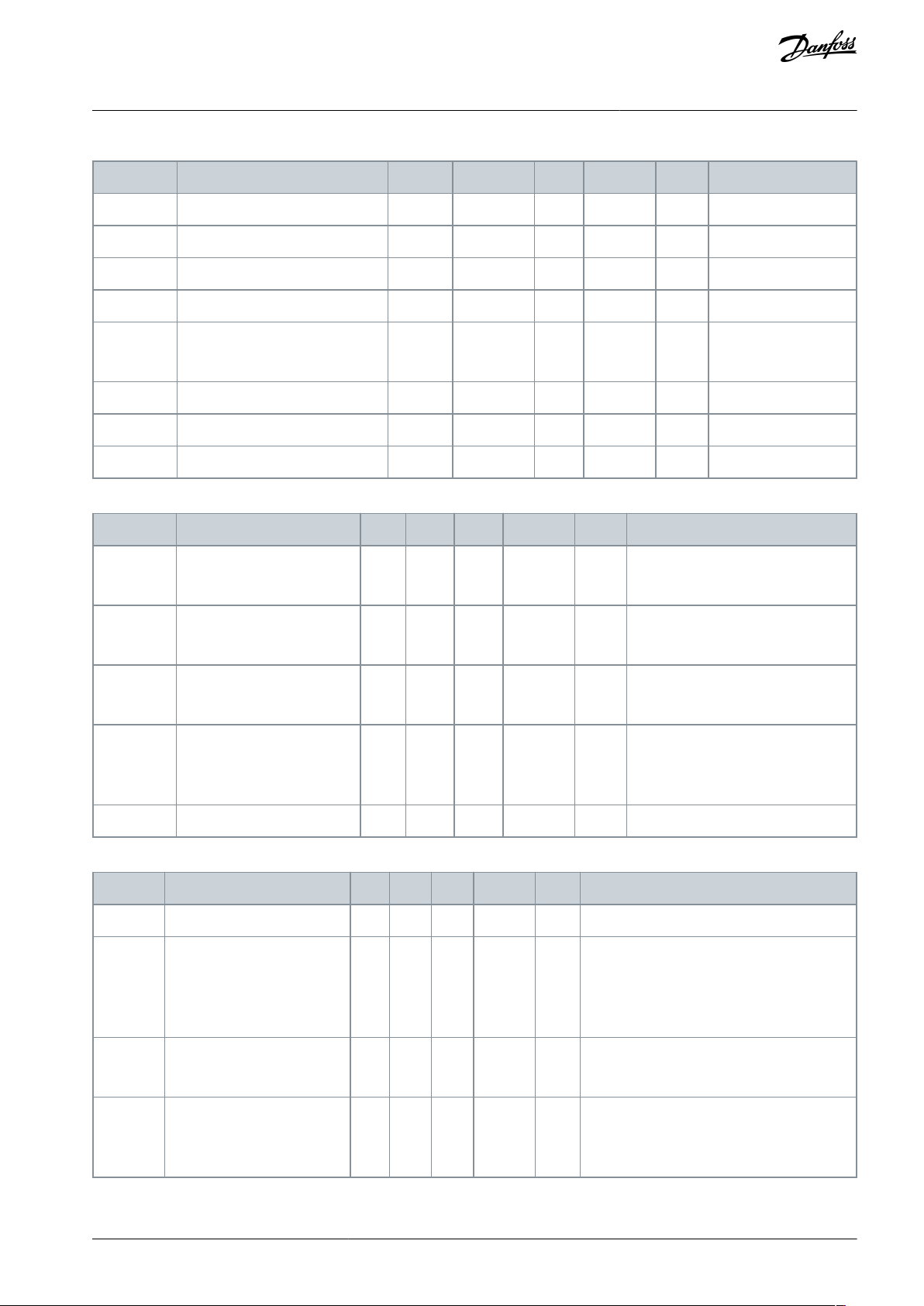
Index
Parameter
Min
Max
Unit
Default
ID
Description
P3.1.2.4.1
CL Speed Control Kp
0.0
200.0
%
30.0
613
P3.1.2.4.2
CL Speed Control Ti
0.001
100 000
s
0.100
614
P3.1.2.4.3
Acceleration comp.TC
0.0000
100.0000
s
0.0000
626
P3.1.2.4.4
Acceleration comp. filter TC
0.0000
10.0000
s
0.0000
4001
P3.1.2.4.5
Load Drooping Mode
010
1534
0 = Normal
1 = Linear removal
P3.1.2.4.6
Load Drooping
0.00
20.00
%
0.00
620
P3.1.2.4.7
Load Drooping Time
0.00
2.00s0.00
656
P3.1.2.4.8
Speed error filter
s
0.0000
4025
Index
Parameter
Min
Max
Unit
Default
ID
Description
P3.1.2.5.1
Overvoltage Control
011
607
0 = Disabled
1 = Enabled
P3.1.2.5.2
Undervoltage Control
011
608
0 = Disabled
1 = Enabled
P3.1.2.5.3
AFE In Use?
010
4003
0 = No
1 = Yes
P3.1.2.5.4
OVC reference selection
0
4004
0 = Supply voltage
1 = DC voltage high maximum
2 = DC voltage high limit
P3.1.2.5.5
OVC reference
V04005
Index
Parameter
Min
Max
Unit
Default
ID
Description
P3.1.2.6.1
Switching Frequency
0.5
2.0
kHz
0.0
601
P3.1.2.6.2
Modulator Type
041
648
1 = SVM
2 = DPWM1
3 = DPWMIN
4 = No 3rd harmonic
P3.1.2.6.3
Modulator Options
032
3301
1 = Deadtime Compensation
2 = Switching Frequency Reduction At Start
P3.1.2.6.4
Synchronous Modulation
044
3302
0 = Synchronous
1 = Asynchronous
4 = Soft Synchronous
VACON® 3000
Application Guide
Table 24: Speed Control Settings
Table 25: Limit Control Settings
INU Application
Table 26: Modulation Settings
AB319735759636en-000101 / DPD01822 | 47Danfoss A/S © 2021.09

Index
Parameter
Min
Max
Unit
Default
ID
Description
P3.1.2.6.5
Maximum Modulation Index
90
105%100
655
P3.1.2.6.6
Fsw Reduction Min
kHz
0.0
3303
P3.1.2.6.7
DC-Link Compensation TC
s
0.0000
3305
Index
Parameter
Min
Max
Unit
Default
ID
Description
P3.1.2.7.1
Magnetizing Current
0
420A0
612
P3.1.2.7.2
Rs Voltage Drop
0.0000
10.0000
%
0.5000
662
P3.1.2.7.3
Ls Voltage Drop
0.0000
50.0000
%
21.0000
673
P3.1.2.7.4
Stator Voltage Adjust
50.0
150.0
%
100.0
659
P3.1.2.7.5
Slip adjust
%
100.0
619
Index
Parameter
Min
Max
Unit
Default
ID
Description
P3.1.2.8.1
Identification
020
631
0 = No action
1 = At standstill
2 = With rotation
P3.1.2.8.2
Identification Options
0
680
P3.1.2.8.3
Magnetizing Current
34.0
680.0
A
0.0
677
P3.1.2.8.4
Rs Voltage Drop
0.0000
10.0000
%
0.0000
675
P3.1.2.8.5
Ls Voltage Drop
0.0000
50.0000
%
0.0000
678
P3.1.2.8.6
Forward Voltage Drop
0.0000
10.0000
%
0.0000
679
Index
Parameter
Min
Max
Unit
Default
ID
Description
P3.1.2.9.1
Regen Filter Select
0
5039
0 = Special
1 = L20.3
2 = L20.3 HSI
3 = L20.4
4 = L20.4 HSI
5 = L30.3
6 = L30.3 HSI
7 = L30.4
8 = L30.4 HSI
P3.1.2.9.2
Special Filter Index
21200
5040
P3.1.2.9.3
Active Damp Resistance
%
20.0
5054
P3.1.2.9.4
Active Damp Cutoff Frequency
Hz
0.00
5055
VACON® 3000
Application Guide
Table 27: Motor Model Settings
Table 28: Identification Settings
INU Application
Table 29: Sine Filter Settings
AB319735759636en-000101 / DPD0182248 | Danfoss A/S © 2021.09

Index
Parameter
Min
Max
Unit
Default
ID
Description
P3.1.3.1
Motor Current Limit
34
420A0
107
P3.1.3.2
Motor Torque Limit
0.0
300.0
%
300.0
1287
P3.1.3.3
Generator Torque Limit
0.0
300.0
%
300.0
1288
P3.1.3.4
Motor Power Limit
0.0
300.0
%
300.0
1289
P3.1.3.5
Generator Power Limit
0.0
300.0
%
300.0
1290
P3.1.3.6
Torque Limit
%
0.0
609
P3.1.3.7
CL motoring torque limit
%
0.0
4020
P3.1.3.8
CL generator torque limit
%
0.0
4021
P3.1.3.9
CL motoring power limit
%
0.0
4022
P3.1.3.10
CL generator power limit
%
0.0
4023
P3.1.3.11
Supply voltage select
Estimated
3355
P3.1.3.12
Set supply voltage
V01201
P3.1.3.13
Motor voltage fault limit
0
4006
P3.1.3.14
Input Phase Fault Ripple Limit
V
0.0
4007
Index
Parameter
Min
Max
Unit
Default
ID
Description
P3.1.4.1
U/f Ratio
020
108
0=Linear
1=Squared
2=Programmable
P3.1.4.2
Field Weakening Point Frequency
8.00
320.00
Hz
0.00
602
P3.1.4.3
Voltage at Field Weakening Point
10.00
200.00
%
100.00
603
P3.1.4.4
U/f Midpoint Fre- quency
0.00
60.00
Hz
0.00
604
P3.1.4.5
U/f Midpoint Voltage
0.0
100.0
%
100.0
605
P3.1.4.6
Zero Frequency Voltage
0.00
40.00
%
0.00
606
P3.1.4.7
Flying Start Options
0630
1590
1 = Disable reverse direction search
2 = Disable AC scanning
4 = Reserved
8 = Reserved
16 = Use the frequency reference for
the initial guess
32 = Disable DC pulses
P3.1.4.8
Flying Start Scan Current
0.0
100.0
%
45.0
1610
P3.1.4.9
Auto Torque Boost
010
109
0=Disabled
1=Enabled
VACON® 3000
Application Guide
Table 30: Motor Limit Settings
INU Application
Table 31: Open Loop Settings
AB319735759636en-000101 / DPD01822 | 49Danfoss A/S © 2021.09

Index
Parameter
Min
Max
Unit
Default
ID
Description
P3.1.4.10
Torque Boost Motor Gain
0.0
100.0
%
100.0
667
P3.1.4.11
Torque Boost Generator Gain
0.0
100.0
%
0.0
665
M3.1.4.12
I/f start
See Table 32.
M3.1.4.13
Stabilators
See Table 33.
Index
Parameter
Min
Max
Unit
Default
ID
Description
P3.1.4.12.1
I/f Start
010
534
0 = Disabled
1 = Enabled
P3.1.4.12.2
I/f Start Frequency
5.0
60.0Hz0.0
535
P3.1.4.12.3
I/f Start Current
0.0
100.0
%
0.0
536
Index
Parameter
Min
Max
Unit
Default
ID
Description
P3.1.4.13.1
Torque stabilator gain
%
0.0
1412
P3.1.4.13.2
Torque stabilator gain FWP
%
0.0
1414
P3.1.4.13.3
Torque stabilator damping time constant
s
0.0000
1413
P3.1.4.13.4
Flux stabilator gain
%01797
P3.1.4.13.5
Flux stabilator damping time constant
s
0.0000
1551
P3.1.4.13.6
Voltage stabilator gain
%
0.0
1738
P3.1.4.13.7
Voltage stabilator damping time constant
s
0.0000
1552
P3.1.4.13.8
Flux trace stabilator gain
%
0.0
1736
P3.1.4.13.9
Flux trace stabilator damping time constant
s
0.0000
1550
Index
Parameter
Min
Max
Unit
Default
ID
Description
P3.1.5.1
Sensorless control
Disabled
1724
P3.1.5.2
Sensorless control mode
0
1725
P3.1.5.3
Sensorless control options
0
1726
P3.1.5.4
Flux mode coefficient 1
0.0
1727
P3.1.5.5
Flux mode coefficient 2
0.0
1728
P3.1.5.6
Flux mode coefficient 3
0.0
1729
P3.1.5.7
Voltage drop IGBT
V
0.00
1730
P3.1.5.8
Offset voltage alpha
%
0.000
1737
P3.1.5.9
Offset voltage beta
%
0.000
1739
VACON® 3000
Application Guide
Table 32: I/f Start Settings
Table 33: Stabilator Settings
INU Application
Table 34: Flux Vector Control Settings
AB319735759636en-000101 / DPD0182250 | Danfoss A/S © 2021.09

•
•
•
•
•
•
•
•
•
•
•
Index
Parameter
Min
Max
Unit
Default
ID
Description
P3.1.5.10
Frequency filter time constant
s
0.012
15647
P3.1.5.11
Flux reference
%
100.0
1250
P3.1.5.12
FW control Kp
%
0.00
4027
P3.1.5.13
FW control Ti
s
0.0000
4028
P3.1.5.14
Flux Ready Limit
%
0.0
4017
Index
Parameter
Min
Max
Unit
Default
ID
Description
P3.2.1
Remote Control Place
0
10172
0 = I/O control
1 = Fieldbus control
P3.2.2
Local/Remote
0
10211
0 = Remote
1 = Local
P3.2.3
Keypad Stop Button
011
114
0 = No
1 = Yes
P3.2.4
Start Function
010
505
0 = Ramping
1 = Flying start
P3.2.5
Stop Function
010
506
0 = Coasting
1 = Ramping
P3.2.6
I/O A Start/Stop Logic
0
42300
Logic = 0
Ctrl sgn 1 = Forward
Ctrl sgn 2 = Backward
Logic = 1
Ctrl sgn 1 = Forward (edge)
Ctrl sgn 2 = Inverted Stop
Ctrl sgn 3 = Bckwrd (edge)
Logic = 2
Ctrl sgn 1 = Forward (edge)
Ctrl sgn 2 = Bckwrd (edge)
Logic = 3
Ctrl sgn 1 = Start
Ctrl sgn 2 = Reverse
Logic = 4
Ctrl sgn 1 = Start (edge)
Ctrl sgn 2 = Reverse
P3.2.7
I/O B Start/Stop Logic
0
42363
See P3.2.6.
P3.2.8
Fieldbus Start Logic
010
889
0 = A rising edge is necessary
VACON® 3000
Application Guide
4.5.2 Group 3.2: Start/Stop Setup
Table 35: Start/Stop Setup
INU Application
AB319735759636en-000101 / DPD01822 | 51Danfoss A/S © 2021.09

Index
Parameter
Min
Max
Unit
Default
ID
Description
1 = State
P3.2.9
Start Delay
0.000
60.000
s
0.00
524
P3.2.10
Remote to Local Function
022
181
0 = Keep Run
1 = Keep Run & Reference
2 = Stop
P3.2.11
Restart delay
s
0.0
1424
P3.2.12
Short restart delay
s
0.0
672
Index
Parameter
Min
Max
Unit
Default
ID
Description
P3.3.1.1
Minimum Frequency Reference
0.00
P3.3.1.2
Hz
0.00
101
P3.3.1.2
Maximum Frequency Reference
P3.3.1.1
320.00
Hz
0.00
102
P3.3.1.3
Positive Frequency Reference Limit
-320.0
320.0
Hz
320.00
1285
P3.3.1.4
Negative Frequency Reference Limit
-320.0
320.0
Hz
-320.00
1286
P3.3.1.5
I/O Control Reference A Selection
1
106117
1 = Preset Frequency 0
2 = Keypad reference
3 = Fieldbus
4 = AI1
5 = AI2
6 = AI1+AI2
7 = PID reference
8 = Motor potentiometer
9 = Joystick reference
10 = Jogging reference
P3.3.1.6
I/O Control Reference B Selection
1
104131
See P3.3.1.5.
P3.3.1.7
Keypad Control Reference Selection
1
102121
1 = Preset Frequency 0
2 = Keypad reference
3 = Fieldbus
4 = AI1
5 = AI2
6 = AI1+AI2
7 = PID reference
8 = Motor potentiometer
9 = Joystick reference
10 = Jogging reference
P3.3.1.8
Keypad Reference
P3.3.1.1
P3.3.1.2
Hz
0.00
184
P3.3.1.9
Keypad Direction
010
123
0 = Forward
VACON® 3000
Application Guide
4.5.3 Group 3.3: References
Table 36: Frequency Reference Parameters
INU Application
AB319735759636en-000101 / DPD0182252 | Danfoss A/S © 2021.09

Index
Parameter
Min
Max
Unit
Default
ID
Description
1 = Reverse
P3.3.1.10
Fieldbus Control Reference Selection
1
103122
1 = Preset Frequency 0
2 = Keypad reference
3 = Fieldbus
4 = AI1
5 = AI2
6 = AI1+AI2
7 = PID reference
8 = Motor potentiometer
9 = Joystick reference
10 = Jogging reference
Index
Parameter
Min
Max
Unit
Default
ID
Description
P3.3.2.1
Torque Reference Selection
0
160641
0 = Not used
1 = Keypad
2 = Joystick
3 = AI1
4 = AI2
5 = AI3
6 = AI4
7 = AI5
8 = AI6
9 = ProcessDataIn 1
10 = ProcessDataIn 2
11 = ProcessDataIn 3
12 = ProcessDataIn 4
13 = ProcessDataIn 5
14 = ProcessDataIn 6
15 = ProcessDataIn 7
16 = ProcessDataIn 8
P3.3.2.2
Torque Minimum Reference
-300.0
300.0
%
0.0
643
P3.3.2.3
Torque Maximum Reference
-300.0
300.0
%
100.0
642
P3.3.2.4
Torque Reference Filter Time
0.00
300.00
s
0.00
1244
P3.3.2.5
Keypad Torque Reference
0.0
P3.3.2.3
%
0.0
1439
P3.3.2.6
Torque control Speed
Limiter Mode
060
1568
0 = NegFreqLimit ... PosFreqLimit
1 = -|FreqRampOut| ... +|FreqRampOut
2 = NegFreqLimit ... FreqRampOut
3 = FreqRampOut ... PosFreqLimit
4 = 0 ... |FreqRampOut| & Direction
VACON® 3000
Application Guide
Table 37: Torque Reference Parameters
INU Application
AB319735759636en-000101 / DPD01822 | 53Danfoss A/S © 2021.09

Index
Parameter
Min
Max
Unit
Default
ID
Description
5 = FreqRampOut +/- Window
6 = FreqRampOut +/- Window with Hystere-
sis
P3.3.2.7
Torque Reference Gain
-800.0
800.0
%
0.0
4015
P3.3.2.8
Torque Reference
Ramp Time
0.0000
1000.0000
s
0.0000
4011
P3.3.2.9
Torque Reference Interpolator Time
0.0000
1000.00 00
s
0.0000
4010
P3.3.2.14
Torque Control Open
Loop
This menu includes 3 parameters. See Table 38.
P3.3.2.15
Torque Control Sensorless
This menu includes 2 parameters. See Table 39.
Index
Parameter
Min
Max
Unit
Default
ID
Description
P3.3.2.14.1
Open Loop Torque Control Minimum Frequency
0.0
P3.3.1.2
Hz
0.0
636
P3.3.2.14.2
Open Loop Torque Control P Gain
0.0
214748. 36
0.00
639
P3.3.2.14.3
Open Loop Torque Control I Gain
0.0
214748. 36
0.00
640
Index
Parameter
Min
Max
Unit
Default
ID
Description
P3.3.2.15.1
Sensorless Torque Control P Gain
0.00
214748.36
0.00
1731
P3.3.2.15.2
Sensorless Torque Control I Gain
0.00
214748.36
0.00
1732
Index
Parameter
Min
Max
Unit
Default
ID
Description
P3.3.3.1
Preset Frequency 0
P3.3.1.1
P3.3.1.2
Hz
5.00
180
P3.3.3.2
Preset Frequency 1
P3.3.1.1
P3.3.1.2
Hz
10.00
105
P3.3.3.3
Preset Frequency 2
P3.3.1.1
P3.3.1.2
Hz
15.00
106
P3.3.3.4
Preset Frequency 3
P3.3.1.1
P3.3.1.2
Hz
20.00
126
P3.3.3.5
Preset Frequency 4
P3.3.1.1
P3.3.1.2
Hz
25.00
127
P3.3.3.6
Preset Frequency 5
P3.3.1.1
P3.3.1.2
Hz
30.00
128
P3.3.3.7
Preset Frequency 6
P3.3.1.1
P3.3.1.2
Hz
40.00
129
P3.3.3.8
Preset Frequency 7
P3.3.1.1
P3.3.1.2
Hz
50.00
130
VACON® 3000
Application Guide
Table 38: Parameters for Torque Control in Open Loop Control
INU Application
Table 39: Parameters for Torque Control in Advanced Sensorless Control
Table 40: Preset Frequency Parameters
AB319735759636en-000101 / DPD0182254 | Danfoss A/S © 2021.09

Index
Parameter
Min
Max
Unit
Default
ID
Description
P3.3.3.9
Preset Frequency Selection 0
DigIN Slot0.1
419
P3.3.3.10
Preset Frequency Selection 1
DigIN Slot0.1
420
P3.3.3.11
Preset Frequency Selection 2
DigIN Slot0.1
421
Index
Parameter
Min
Max
Unit
Default
ID
Description
P3.3.4.1
Motor Potentiometer UP
DigIN Slot0.1
418
OPEN = Not active
CLOSED = Active
P3.3.4.2
Motor Potentiometer DOWN
DigIN Slot0.1
417
OPEN = Not active
CLOSED = Active
P3.3.4.3
Motor Potentiometer Ramp Time
0.1
500.0
Hz/s
10.0
331
P3.3.4.4
Motor Potentiometer Reset
021
367
0 = No reset
1 = Reset if stopped
2 = Reset if powered down
Index
Parameter
Min
Max
Unit
Default
ID
Description
P3.3.5.1
Joystick Signal Selection
060
451
0 = Not Used
1 = AI1 (0–100%)
2 = AI2 (0–100%)
3 = AI3 (0–100%)
4 = AI4 (0–100%)
5 = AI5 (0–100%)
6 = AI6 (0–100%)
P3.3.5.2
Joystick Dead Zone
0.0
20.0%2.0
384
P3.3.5.3
Joystick Sleep Delay
0.00
300.00
s
0.00
386
0 = Not used
Index
Parameter
Min
Max
Unit
Default
ID
Description
P3.3.6.1
Enable DI Jogging
Varies
Varies
DigIN Slot0.1
532
P3.3.6.2
Jogging Reference 1 Activation
Varies
Varies
DigIN Slot0.1
530
P3.3.6.3
Jogging Reference 2 Activation
Varies
Varies
DigIN Slot0.1
531
VACON® 3000
Application Guide
Table 41: Motor Potentiometer Parameters
INU Application
Table 42: Joystick Control Parameters
Table 43: Jogging Parameters
AB319735759636en-000101 / DPD01822 | 55Danfoss A/S © 2021.09

Index
Parameter
Min
Max
Unit
Default
ID
Description
P3.3.6.4
Jogging Reference 1
-MaxRef
MaxRef
Hz
0.00
1239
P3.3.6.5
Jogging Reference 2
-MaxRef
MaxRef
Hz
0.00
1240
P3.3.6.6
Jogging Ramp
0.1
300.0
s
10.0
1257
Index
Parameter
Min
Max
Unit
Default
ID
Description
P3.4.1.1
Ramp 1 Shape
0.0
100.0
%
0.0
500
P3.4.1.2
Acceleration Time 1
0.1
300.0
s
5.0
103
P3.4.1.3
Deceleration Time 1
0.1
300.0
s
5.0
104
Index
Parameter
Min
Max
Unit
Default
ID
Description
P3.4.2.1
Ramp 2 Shape
0.0
100.0
%
0.0
501
P3.4.2.2
Acceleration Time 2
0.1
300.0
s
10.0
502
P3.4.2.3
Deceleration Time 2
0.1
300.0
s
10.0
503
P3.4.2.4
Ramp 2 Selection
Varies
Varies
DigIN Slot0.1
408
0 = OPEN
1 = CLOSED
Index
Parameter
Min
Max
Unit
Default
ID
Description
P3.4.3.1
Start Magnetizing Current
0.00ILAIH517
0 = Disabled
P3.4.3.2
Start Magnetizing Time
0.00
600.00
s
0.00
516
Index
Parameter
Min
Max
Unit
Default
ID
Description
P3.4.4.1
DC Brake Current
0ILAIH507
0 = Disabled
P3.4.4.2
DC Braking Time at Stop
0.00
600.00
s
0.00
508
P3.4.4.3
Frequency to Start DC Braking at Ramp Stop
0.10
10.00
Hz
1.50
515
VACON® 3000
Application Guide
4.5.4 Group 3.4: Ramps and Brakes Setup
Table 44: Ramp 1 Setup
INU Application
Table 45: Ramp 2 Setup
Table 46: Start Magnetization Parameters
Table 47: DC Brake Parameters
AB319735759636en-000101 / DPD0182256 | Danfoss A/S © 2021.09

Index
Parameter
Min
Max
Unit
Default
ID
Description
P3.4.5.1
Flux Braking
010
520
0 = Disabled
1 = Enabled
P3.4.5.2
Flux Braking Current
0ILAIH519
Index
Parameter
Min
Max
Unit
Default
ID
Description
P3.5.1.1
Control Signal 1 A
DigIN Slot0.1
403
P3.5.1.2
Control Signal 2 A
DigIN Slot0.1
404
P3.5.1.3
Control Signal 3 A
DigIN Slot0.1
434
P3.5.1.4
Control Signal 1 B
DigIN Slot0.1
423
P3.5.1.5
Control Signal 2 B
DigIN Slot0.1
424
P3.5.1.6
Control Signal 3 B
DigIN Slot0.1
435
P3.5.1.7
I/O B Control Force
DigIN Slot0.1
425
CLOSED = Force the control place to
I/O B
P3.5.1.8
I/O B Reference Force
DigIN Slot0.1
343
CLOSED = I/O reference B (P3.3.1.6)
gives the frequency reference
P3.5.1.9
Fieldbus Control Force
DigIN Slot0.1
411
P3.5.1.10
Keypad Control Force
DigIN Slot0.1
410
P3.5.1.11
External Fault Close
DigIN Slot0.1
405
OPEN = OK
CLOSED = External fault
P3.5.1.12
External Fault Open
DigIN Slot0.2
406
OPEN = External fault
CLOSED = OK
P3.5.1.13
Fault Reset Close
DigIN Slot0.1
414
CLOSED = Resets all active faults
P3.5.1.14
Fault Reset Open
DigIN Slot0.1
213
OPEN = Resets all active faults
P3.5.1.15
Run Enable
DigIN SlotA.1
407
P3.5.1.16
Run Interlock 1
DigIN Slot0.2
1041
P3.5.1.17
Run Interlock 2
DigIN Slot0.2
1042
P3.5.1.18
Ramp 2 Selection
DigIN Slot0.1
408
OPEN = Ramp 1 Shape, Acceleration
Time 1, and Deceleration Time 1.
VACON® 3000
Application Guide
Table 48: Flux Braking Parameters
4.5.5 Group 3.5: I/O Configuration
Table 49: Digital Input Settings
INU Application
AB319735759636en-000101 / DPD01822 | 57Danfoss A/S © 2021.09

Index
Parameter
Min
Max
Unit
Default
ID
Description
CLOSED = Ramp 2 Shape, Acceleration Time 2, and Deceleration Time 2.
P3.5.1.19
Acc/Dec Prohibit
DigIN Slot0.1
415
P3.5.1.20
Preset Frequency Selection 0
DigIN Slot0.1
419
P3.5.1.21
Preset Frequency Selection 1
DigIN Slot0.1
420
P3.5.1.22
Preset Frequency Selection 2
DigIN Slot0.1
421
P3.5.1.23
Motor Potentiometer UP
DigIN Slot0.1
418
OPEN = Not active
CLOSED = Active
P3.5.1.24
Motor Potentiometer DOWN
DigIN Slot0.1
417
OPEN = Not active
CLOSED = Active
P3.5.1.25
Quick Stop Activation
DigIN Slot0.2
1213
OPEN = Activated
P3.5.1.26
PID1 Select Setpoint
DigIN Slot0.1
1047
OPEN = Setpoint 1
CLOSED = Setpoint 2
P3.5.1.27
Enable DI Jogging
DigIN Slot0.1
532
P3.5.1.28
Jogging Reference 1 Activation
DigIN Slot0.1
530
P3.5.1.29
Jogging Reference 2 Activation
DigIN Slot0.1
531
P3.5.1.30
Mechanical Brake Feedback
DigIN Slot0.1
1210
P3.5.1.31
Parameter Set 1/2 Selection
DigIN Slot0.1
496
OPEN = Parameter set 1
CLOSED = Parameter set 2
P3.5.1.32
User Defined Fault 1 Activation
DigIN Slot0.1
15523
OPEN = No action
CLOSED = Fault activated
P3.5.1.33
User Defined Fault 2 Activation
DigIN Slot0.1
15524
OPEN = No action
CLOSED = Fault activated
P3.5.1.34
Power on
DigIN Slot0.1
3550
P3.5.1.35
Power off
DigIN Slot0.1
3551
P3.5.1.36
Reset power on state
DigIN Slot0.1
3552
P3.5.1.37
GSW Unlock
DigIN Slot0.1
3553
P3.5.1.38
STO Status
DigIN Slot0.1
4401
P3.5.1.39
Output Inductor TempSW 1
DigIN Slot0.2
3700
P3.5.1.40
Output Inductor TempSW 2
DigIN Slot0.2
3701
P3.5.1.41
Output Inductor TempSW 3
DigIN Slot0.2
3702
VACON® 3000
Application Guide
INU Application
AB319735759636en-000101 / DPD0182258 | Danfoss A/S © 2021.09

Index
Parameter
Min
Max
Unit
Default
ID
Description
P3.5.1.42
Output Inductor TempSW 4
DigIN Slot0.2
3703
P3.5.1.43
Output RC TempSW 1
DigIN Slot0.2
3704
P3.5.1.44
Output RC TempSW 2
DigIN Slot0.2
3705
P3.5.1.45
Output RC TempSW 3
DigIN Slot0.2
3706
P3.5.1.46
Output RC TempSW 4
DigIN Slot0.2
3707
P3.5.1.47
Output RC PressSW 1
DigIN Slot0.2
3708
P3.5.1.48
Output RC PressSW 2
DigIN Slot0.2
3709
P3.5.1.49
Output RC PressSW 3
DigIN Slot0.2
3710
P3.5.1.50
Output RC PressSW 4
DigIN Slot0.2
3711
Index
Parameter
Min
Max
Unit
Default
ID
Description
P3.5.2.1.1
AI1 Signal Selection
AnIN SlotA.1
377
P3.5.2.1.2
AI1 Signal Filter Time
0.00
300.00
s
0.10
378
P3.5.2.1.3
AI1 Signal Range
0
10379
0 = 0…10 V / 0…20 mA
1 = 2…10 V / 4…20 mA
P3.5.2.1.4
AI1 Custom. Min
-160.00
160.00
%
0.00
380
P3.5.2.1.5
AI1 Custom. Max
-160.00
160.00
%
100.00
381
P3.5.2.1.6
AI1 Signal Inversion
0
10387
0 = Normal
1 = Signal inverted
Index
Parameter
Min
Max
Unit
Default
ID
Description
P3.5.2.2.1
AI2 Signal Selection
AnIN SlotA.2
388
See P3.5.2.1.1.
P3.5.2.2.2
AI2 Signal Filter Time
0.00
300.00
s
0.10
389
See P3.5.2.1.2.
P3.5.2.2.3
AI2 Signal Range
0
11390
See P3.5.2.1.3.
P3.5.2.2.4
AI2 Custom. Min
-160.00
160.00
%
0.00
391
See P3.5.2.1.4.
P3.5.2.2.5
AI2 Custom. Max
-160.00
160.00
%
100.00
392
See P3.5.2.1.5.
P3.5.2.2.6
AI2 Signal Inversion
0
10398
See P3.5.2.1.6.
VACON® 3000
Application Guide
Table 50: Analog Input 1 Settings
INU Application
Table 51: Analog Input 2 Settings
AB319735759636en-000101 / DPD01822 | 59Danfoss A/S © 2021.09
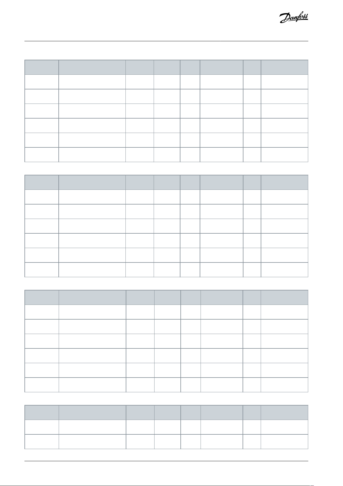
Index
Parameter
Min
Max
Unit
Default
ID
Description
P3.5.2.3.1
AI3 Signal Selection
AnIN SlotD.1
141
See P3.5.2.1.1.
P3.5.2.3.2
AI3 Signal Filter Time
0.00
300.00
s
0.10
142
See P3.5.2.1.2.
P3.5.2.3.3
AI3 Signal Range
010
143
See P3.5.2.1.3.
P3.5.2.3.4
AI3 Custom. Min
-160.00
160.00
%
0.00
144
See P3.5.2.1.4.
P3.5.2.3.5
AI3 Custom. Max
-160.00
160.00
%
100.00
145
See P3.5.2.1.5.
P3.5.2.3.6
AI3 Signal Inversion
0
10151
See P3.5.2.1.6.
Index
Parameter
Min
Max
Unit
Default
ID
Description
P3.5.2.4.1
AI4 Signal Selection
AnIN SlotD.2
152
See P3.5.2.1.1.
P3.5.2.4.2
AI4 Signal Filter Time
0.00
300.00
s
0.10
153
See P3.5.2.1.2.
P3.5.2.4.3
AI4 Signal Range
010
154
See P3.5.2.1.3.
P3.5.2.4.4
AI4 Custom. Min
-160.00
160.00
%
0.00
155
See P3.5.2.1.4.
P3.5.2.4.5
AI4 Custom. Max
-160.00
160.00
%
100.00
156
See P3.5.2.1.5.
P3.5.2.4.6
AI4 Signal Inversion
010
162
See P3.5.2.1.6.
Index
Parameter
Min
Max
Unit
Default
ID
Description
P3.5.2.5.1
AI5 Signal Selection
AnIN SlotE.1
188
See P3.5.2.1.1.
P3.5.2.5.2
AI5 Signal Filter Time
0.00
300.00
s
0.10
189
See P3.5.2.1.2.
P3.5.2.5.3
AI5 Signal Range
010
190
See P3.5.2.1.3.
P3.5.2.5.4
AI5 Custom. Min
-160.00
160.00
%
0.00
191
See P3.5.2.1.4.
P3.5.2.5.5
AI5 Custom. Max
-160.00
160.00
%
100.00
192
See P3.5.2.1.5.
P3.5.2.5.6
AI5 Signal Inversion
010
198
See P3.5.2.1.6.
Index
Parameter
Min
Max
Unit
Default
ID
Description
P3.5.2.6.1
AI6 Signal Selection
AnIN SlotE.2
199
See P3.5.2.1.1.
P3.5.2.6.2
AI6 Signal Filter Time
0.00
300.00
s
0.10
200
See P3.5.2.1.2.
VACON® 3000
Application Guide
Table 52: Analog Input 3 Settings
Table 53: Analog Input 4 Settings
INU Application
Table 54: Analog Input 5 Settings
Table 55: Analog Input 6 Settings
AB319735759636en-000101 / DPD0182260 | Danfoss A/S © 2021.09

Index
Parameter
Min
Max
Unit
Default
ID
Description
P3.5.2.6.3
AI6 Signal Range
010
201
See P3.5.2.1.3.
P3.5.2.6.4
AI6 Custom. Min
-160.00
160.00
%
0.00
203
See P3.5.2.1.4.
P3.5.2.6.5
AI6 Custom. Max
-160.00
160.00
%
100.00
204
See P3.5.2.1.5.
P3.5.2.6.6
AI6 Signal Inversion
010
209
See P3.5.2.1.6.
Index
Parameter
Min
Max
Unit
Default
ID
Description
P3.5.3.2.1
RO1 Function
0403
11001
0 = Not used
1 = Test (always closed)
2 = Ready
3 = Run
4 = Fault
5 = Fault inverted
6 = Alarm
7 = Reverse
8 = At speed
9 = Thermistor fault
10 = Motor regulator active
11 = Start signal active
12 = Keypad control active
13 = I/O B control activated
14 = Limit supervision1
15 = Limit supervision2
16 = Jogging activated
17 = Preset frequency active
18 = Quick stop active
19 = PID in Sleep mode
20 = Fieldbus Control- Word B13
21 = Fieldbus Control- Word B14
22 = Fieldbus Control- Word B15
23 = Fieldbus Process- Data1.B0
24 = Fieldbus Process- Data1.B1
25 = Fieldbus Process- Data1.B2
26 = Mechanical brake (Open brake command)
27 = Mechanical brake inverted
28 = Motor Switch Open
29 = Mains contactor permissive
30 = Mains contactor close
31 = Precharge permissive
32 = INU run enable
VACON® 3000
Application Guide
INU Application
N O T I C E
Shows only the parameters for the outputs on option boards in slots C, D, and E. Make the selections as in RO1 Function
(P3.5.3.2.1). This group or these parameters are not visible if there are no digital outputs in slots C, D, or E.
Table 56: Digital Output Settings on Standard I/O Board
AB319735759636en-000101 / DPD01822 | 61Danfoss A/S © 2021.09

Index
Parameter
Min
Max
Unit
Default
ID
Description
33 = Precharge ready
34 = Precharge started
35 = Precharge inhibit
36 = Precharge coil
37 = HXL coil
38 = MV HX coil
39 = LV HX coil
40 = MCB coil
P3.5.3.2.2
RO1 ON Delay
0.00
320.00
s
0.00
11002
P3.5.3.2.3
RO1 OFF
Delay
0.00
320.00
s
0.00
11003
P3.5.3.2.4
RO2 Function
0564
11004
See P3.5.3.2.1.
P3.5.3.2.5
RO2 ON Delay
0.00
320.00
s
0.00
11005
See P3.5.3.2.2.
P3.5.3.2.6
RO2 OFF
Delay
0.00
320.00
s
0.00
11006
See P3.5.3.2.3.
P3.5.3.2.7
RO3 Function
0562
11007
See P3.5.3.2.1. Not visible if only 2 output relays are installed.
P3.5.3.2.8
RO3 ON Delay
0.00
320.00
s
0.00
11008
See P3.5.3.2.2. Not visible if only 2 output relays are installed.
P3.5.3.2.9
RO3 OFF
Delay
0.00
320.00
s
0.00
11009
See P3.5.3.2.3. Not visible if only 2 output relays are installed.
Index
Parameter
Min
Max
Unit
Default
ID
Description
P3.5.3.6.1
RO1 Function
0210
6040
0 = Not used
1 = Test (always closed)
2 = Ready
3 = Run
4 = Fault
5 = Fault inverted
6 = Alarm
7 = Fieldbus Control- Word B13
8 = Fieldbus Control- Word B14
9 = Fieldbus Control- Word B15
10 = Fieldbus Process- Data1.B0
11 = Fieldbus Process- Data1.B1
12 = Fieldbus Process- Data1.B2
13 = Main contactor permissive
14 = Main contactor close
VACON® 3000
Application Guide
INU Application
Table 57: Digital Output Settings on MV Star Board
AB319735759636en-000101 / DPD0182262 | Danfoss A/S © 2021.09

Index
Parameter
Min
Max
Unit
Default
ID
Description
15 = Precharge permissive
16 = GSW unlock
17 = Run cooling
18 = Close breaker
19 = STO active
20 = Pulse close breaker
21 = Pulse open breaker
P3.5.3.6.2
RO2 Function
0210
6041
See ID 6040.
P3.5.3.6.3
RO3 Function
0210
6042
See ID 6040.
Index
Parameter
Min
Max
Unit
Default
ID
Description
P3.5.4.1.1
AO1 function
0
31210050
0 = TEST 0%
1 = TEST 100%
2 = Output freq (0 - fmax)
3 = Freq reference (0 - fmax)
4 = Motor speed (0 - Motor nominal speed)
5 = Output current (0 - InMotor)
6 = Motor torque (0 - TnMotor)
7 = Motor power (0 - PnMotor)
8 = Motor voltage (0 - UnMotor)
9 = DC-link voltage (0 - 1000V)
10 = PID Setpoint (0-100%)
11 = PID Feedback (0-100%)
12 = PID output (0-100%)
13 = ProcessDataIn1 (0-100%)
14 = ProcessDataIn2 (0-100%)
15 = ProcessDataIn3 (0-100%)
16 = ProcessDataIn4 (0-100%)
17 = ProcessDataIn5 (0-100%)
18 = ProcessDataIn6 (0-100%)
19 = ProcessDataIn7 (0-100%)
20 = ProcessDataIn8 (0-100%)
P3.5.4.1.2
AO1 filter time
0.0
300.0
s
1.00
10051
0 = No filtering
P3.5.4.1.3
AO1 minimum signal
0
1010052
0 = 0 mA / 0 V
1 = 4 mA / 2 V
P3.5.4.1.4
AO1 minimum scale
Hz
0.00
10053
P3.5.4.1.5
AO1 maximum scale
Hz
0.00
10054
VACON® 3000
Application Guide
INU Application
N O T I C E
Shows only the parameters for the outputs on option boards in slots C, D, and E. Make the selections as in Basic AO1 Function
(P3.5.4.1.1). This group or these parameters are not visible if there are no digital outputs in slots C, D, or E.
Table 58: Analog Output Settings on Standard I/O board
AB319735759636en-000101 / DPD01822 | 63Danfoss A/S © 2021.09

Index
Parameter
Min
Max
Unit
Default
ID
Description
P3.6.1
Fieldbus Data Out 1 Selection
0
35000
1
852
P3.6.2
Fieldbus Data Out 2 Selection
0
35000
2
853
P3.6.3
Fieldbus Data Out 3 Selection
0
35000
3
854
P3.6.4
Fieldbus Data Out 4 Selection
0
35000
4
855
P3.6.5
Fieldbus Data Out 5 Selection
0
35000
5
856
P3.6.6
Fieldbus Data Out 6 Selection
0
35000
6
857
P3.6.7
Fieldbus Data Out 7 Selection
0
35000
7
858
P3.6.8
Fieldbus Data Out 8 Selection
0
35000
37
859
P3.6.9
Fieldbus Data Out 9 Selection
0
35000
0
890
P3.6.10
Fieldbus Data Out 10 Selection
0
35000
0
891
P3.6.11
Fieldbus Data Out 11 Selection
0
35000
0
892
P3.6.12
Fieldbus Data Out 12 Selection
0
35000
0
893
P3.6.13
Fieldbus Data Out 13 Selection
0
35000
0
894
P3.6.14
Fieldbus Data Out 14 Selection
0
35000
0
895
P3.6.15
Fieldbus Data Out 15 Selection
0
35000
0
896
P3.6.16
Fieldbus Data Out 16 Selection
0
35000
0
897
P3.6.17
Fieldbus Data In 1 Selection
0
6400
P3.6.18
Fieldbus Data In 2 Selection
0
6401
P3.6.19
Fieldbus Data In 3 Selection
0
6402
P3.6.20
Fieldbus Data In 4 Selection
0
6403
P3.6.21
Fieldbus Data In 5 Selection
0
6404
P3.6.22
Fieldbus Data In 6 Selection
0
6405
P3.6.23
Fieldbus Data In 7 Selection
0
6406
P3.6.24
Fieldbus Data In 8 Selection
0
6407
P3.6.25
Fieldbus Data In 9 Selection
0
6408
P3.6.26
Fieldbus Data In 10 Selection
0
6409
P3.6.27
Fieldbus Data In 11 Selection
0
6410
VACON® 3000
Application Guide
4.5.6 Group 3.6: Fieldbus Data Mapping
Table 59: Fieldbus Data Mapping parameters
INU Application
AB319735759636en-000101 / DPD0182264 | Danfoss A/S © 2021.09

Index
Parameter
Min
Max
Unit
Default
ID
Description
P3.6.28
Fieldbus Data In 12 Selection
0
6411
P3.6.29
Fieldbus Data In 13 Selection
0
6412
P3.6.30
Fieldbus Data In 14 Selection
0
6413
P3.6.31
Fieldbus Data In 15 Selection
0
6414
P3.6.32
Fieldbus Data In 16 Selection
0
6415
P3.6.33
Fieldbus profile
121
6417
1 = Standard
2 = Bypass
Data
Default Value
Scale
Process Data Out 1
Output frequency
0.01 Hz
Process Data Out 2
Motor speed
1 rpm
Process Data Out 3
Motor current
0.1 A
Process Data Out 4
Motor torque
0.1%
Process Data Out 5
Motor power
0.1%
Process Data Out 6
Motor voltage
0.1 V
Process Data Out 7
DC link voltage
1 V
Process Data Out 8
Last active fault code
1
Index
Parameter
Min
Max
Unit
Default
ID
Description
P3.7.1
Prohibit Frequency Range 1 Low Limit
-1.00
320.00
Hz
0.00
509
0 = Not used
P3.7.2
Prohibit Frequency Range 1 High Limit
0.00
320.00
Hz
0.00
510
0 = Not used
P3.7.3
Prohibit Frequency Range 2 Low Limit
0.00
320.00
Hz
0.00
511
0 = Not used
P3.7.4
Prohibit Frequency Range 2 High Limit
0.00
320.00
Hz
0.00
512
0 = Not used
P3.7.5
Prohibit Frequency Range 3 Low Limit
0.00
320.00
Hz
0.00
513
0 = Not used
P3.7.6
Prohibit Frequency Range 3 High Limit
0.00
320.00
Hz
0.00
514
0 = Not used
P3.7.7
Ramp Time Factor
0.1
10.0
Times
1.0
518
VACON® 3000
Application Guide
Table 60: The default values for Process Data Out in fieldbus
INU Application
Example
The value 2500 for Output frequency equals 25.00 Hz, because the scale is 0.01. All the monitoring values that you can find in the
Monitor menu are given the scale value.
4.5.7 Group 3.7: Prohibit Frequencies
Table 61: Prohibit Frequencies Parameters
AB319735759636en-000101 / DPD01822 | 65Danfoss A/S © 2021.09

Index
Parameter
Min
Max
Unit
Default
ID
Description
P3.8.1
Supervision #1 Item Selection
0140
1431
0 = Output frequency
1 = Frequency reference
2 = Motor current
3 = Motor torque
4 = Motor power
5 = DC-link voltage
6 = Analogue input 1
7 = Analogue input 2
8 = Analogue input 3
9 = Analogue input 4
10 = Analogue input 5
11 = Analogue input 6
12 = Temperature input 1
13 = Temperature input 2
14 = Temperature input 3
P3.8.2
Supervision #1 Mode
020
1432
0 = Not used
1 = Low limit supervision
2 = High limit supervision
P3.8.3
Supervision #1 Limit
-50.00
50.00
Varies
25.00
1433
P3.8.4
Supervision #1 Limit Hysteresis
0.00
50.00
Varies
5.00
1434
P3.8.5
Supervision #2 Item Selection
0171
1435
See P3.8.1
P3.8.6
Supervision #2 Mode
020
1436
See P3.8.2
P3.8.7
Supervision #2 Limit
-50.00
50.00
Varies
40.00
1437
P3.8.8
Supervision #2 Limit Hysteresis
0.00
50.00
Varies
5.00
1438
Index
Parameter
Min
Max
Unit
Default
ID
Description
P3.9.1.1
Preset Alarm Frequency
P3.3.1.1
P3.3.1.2
Hz
25.00
183
P3.9.1.2
Response to External Fault
032
701
0 = No action
1 = Alarm
2 = Fault (Stop according to stop
function)
3 = Fault (Stop by coasting)
P3.9.1.3
Undervoltage Fault
010
727
0 = Fault stored in history
1 = Fault not stored in history
P3.9.1.4
Response to Output Phase
Fault
032
702
See P3.9.1.2.
VACON® 3000
Application Guide
4.5.8 Group 3.8 Supervisions
Table 62: Supervision Settings
INU Application
4.5.9 Group 3.9: Protections
Table 63: General protection settings
AB319735759636en-000101 / DPD0182266 | Danfoss A/S © 2021.09

Index
Parameter
Min
Max
Unit
Default
ID
Description
P3.9.1.5
Response to Fieldbus Communication Fault
053
733
0 = No action
1 = Alarm
2 = Alarm + preset fault frequency
(P3.9.1.1)
3 = Fault (Stop according to stop
function)
4 = Fault (Stop by coasting)
P3.9.1.6
Slot Communication Fault
032
734
See P3.9.1.2.
P3.9.1.7
Thermistor Fault
030
732
See P3.9.1.2.
P3.9.1.8
Earth Fault
033
703
See P3.9.1.2.
P3.9.1.9
Response to Safe Torque Off
(STO) Fault
022
775
0 = No action
1 = Alarm
2 = Fault (Stop by coasting)
P3.9.1.10
Fieldbus watchdog fault
mode
030
1807
See ID 701
P3.9.1.11
Fieldbus watchdog delay
s
2.00
1808
0 = Watchdog disabled
P3.9.1.12
Startup Prevented Fault
010
15593
0 = Fault
1 = No action
P3.9.1.13
Redundant Switchover Indication
021
750
0 = No action
1 = Alarm
2 = Alarm + Autoreset
P3.9.1.14
FBCommFlt Force Delay
s
0.00
751
P3.9.1.15
FBCommFlt Clear Delay
s
0.00
752
P3.9.1.17
Output Filter
033
4038
0 = No action
1 = Alarm
2 = Fault
3 = Fault, coast
P3.9.1.18
Enclosure Humidity and Temperature
031
3360
0 = No action
1 = Alarm
2 = Fault
3 = Fault, coast
P3.9.1.19
Current imbalance - Belt
021
4039
0 = No action
1 = Alarm
2 = Fault, coast
P3.9.1.20
Neutral to ground fault response
011
4040
0 = No action
1 = Fault, coast
VACON® 3000
Application Guide
INU Application
AB319735759636en-000101 / DPD01822 | 67Danfoss A/S © 2021.09

Index
Parameter
Min
Max
Unit
Default
ID
Description
P3.9.2.1
Motor Thermal Protection
032
704
0 = No action
1 = Alarm
2 = Fault (Stop by stop mode)
3 = Fault (Stop by coasting)
P3.9.2.2
Ambient Temperature
-20.0
100.0
°C
40.0
705
P3.9.2.3
Zero Speed Cooling Factor
5.0
150.0
%
Varies
706
P3.9.2.4
Motor Thermal Time Constant
1
200
min
Varies
707
P3.9.2.5
Motor Thermal Loadability
10
150%100
708
Index
Parameter
Min
Max
Unit
Default
ID
Description
P3.9.3.1
Motor Stall Fault
030
709
0 = No action
1 = Alarm
2 = Fault (Stop according to stop mode)
3 = Fault (Stop by coasting)
P3.9.3.2
Stall Current
0.00
Varies
A0710
P3.9.3.3
Stall Time Limit
1.00
120.00
s
15.00
711
P3.9.3.4
Stall Frequency Limit
1.00
P3.3.1.2
Hz
25.00
712
Index
Parameter
Min
Max
Unit
Default
ID
Description
P3.9.4.1
Underload Fault
030
713
0 = No action
1 = Alarm
2 = Fault (Stop according to stop
mode)
3 = Fault (Stop by coasting)
P3.9.4.2
Underload Protection: Field Weakening
Area Load
10.0
150.0
%
50.0
714
P3.9.4.3
Underload Protection: Zero Frequency
Load
5.0
150.0
%
10.0
715
P3.9.4.4
Underload Protection: Time Limit
2.00
600.00
s
20.00
716
Index
Parameter
Min
Max
Unit
Default
ID
Description
P3.9.5.1
Quick Stop Mode
021
1276
0 = Coasting
1 = Quick stop deceleration time
VACON® 3000
Application Guide
Table 64: Motor thermal protection settings
Table 65: Motor stall protection settings
INU Application
Table 66: Motor underload protection settings
Table 67: Quick stop settings
AB319735759636en-000101 / DPD0182268 | Danfoss A/S © 2021.09

Index
Parameter
Min
Max
Unit
Default
ID
Description
2 = Stop according to Stop function
(P3.2.5)
P3.9.5.2
Quick Stop Activation
Varies
Varies
DigIN Slot0.2
1213
OPEN = Activated
P3.9.5.3
Quick Stop Deceleration
Time
0.1
300.0
s
3.0
1256
P3.9.5.4
Response to Quick Stop
Fault
021
744
0 = No action
1 = Alarm
2 = Fault (Stop according to Quick stop
mode)
Index
Parameter
Min
Max
Unit
Default
ID
Description
P3.9.6.1
(1)
Temperature Signal 1
0630
739
B0 = Temperature Signal 1
B1 = Temperature Signal 2
B2 = Temperature Signal 3
P3.9.6.2
(1)
Alarm Limit 1
-30.0
200.0
°C
130.0
741
P3.9.6.3
(1)
Fault Limit 1
-30.0
200.0
°C
155.0
742
P3.9.6.4
(1)
Fault Limit Response 1
032
740
0 = No response
1 = Alarm
2 = Fault (Stop according to stop mode)
3 = Fault (Stop by coasting)
Index
Parameter
Min
Max
Unit
Default
ID
Description
P3.9.7.1
(1)
Temperature Signal 2
0630
763
B0 = Temperature Signal 1
B1 = Temperature Signal 2
B2 = Temperature Signal 3
P3.9.7.2
(1)
Alarm Limit 2
-30.0
200.0
°C
130.0
764
P3.9.7.3
(1)
Fault Limit 2
-30.0
200.0
°C
155.0
765
P3.9.7.4
(1)
Fault Limit Response 2
032
766
0 = No response
1 = Alarm
2 = Fault (Stop according to stop mode)
3 = Fault (Stop by coasting)
VACON® 3000
Application Guide
Table 68: Temperature input fault 1 settings
INU Application
1
Temperature input settings are only available if a B8 or BH option board is installed.
Table 69: Temperature input fault 2 settings
1
Temperature input settings are only available if a B8 or BH option board is installed.
AB319735759636en-000101 / DPD01822 | 69Danfoss A/S © 2021.09

Index
Parameter
Min
Max
Unit
Default
ID
Description
P3.9.8.1
Analog Input Low Protection
022
767
0 = No protection
1 = Protection enabled in Run state
2 = Protection enabled in Run and Stop state
P3.9.8.2
Analog Input Low Fault
050
700
0 = No action
1 = Alarm
2 = Alarm + preset fault frequency (P3.9.1.1)
3 = Alarm + previous frequency reference
4 = Fault (Stop according to stop mode)
5 = Fault (Stop by coasting)
Index
Parameter
Min
Max
Unit
Default
ID
Description
P3.9.9.1
User Defined Fault 1
--DigIN Slot0.1
15523
OPEN = No operation
CLOSED = Fault activated
P3.9.9.2
Response to User Defined
Fault 1
033
15525
0 = No action
1 = Alarm
2 = Fault (Stop according to stop function)
3 = Fault (Stop by coasting)
Index
Parameter
Min
Max
Unit
Default
ID
Description
P3.9.10.1
User Defined Fault 2
--DigIN Slot0.1
15524
OPEN = No operation
CLOSED = Fault activated
P3.9.10.2
Response to User Defined
Fault 2
033
15526
0 = No action
1 = Alarm
2 = Fault (Stop according to stop function)
3 = Fault (Stop by coasting)
Index
Parameter
Min
Max
Unit
Default
ID
Description
P3.9.11.1
Speed error fault response
030
4032
0 = No action
1 = Alarm
2 = Fault (Stop according to stop function)
3 = Fault (Stop by coasting)
P3.9.11.2
Speed error limit
%
0.00
4030
P3.9.11.3
Speed error delay
s
0.00
4031
P3.9.11.4
Over speed fault response
0
780
See P3.9.11.1.
VACON® 3000
Application Guide
Table 70: AI low protection settings
Table 71: User Defined Fault 1
INU Application
Table 72: User Defined Fault 2
Table 73: Speed Error
AB319735759636en-000101 / DPD0182270 | Danfoss A/S © 2021.09

Index
Parameter
Min
Max
Unit
Default
ID
Description
P3.9.11.5
Speed Delta Error Fault Response
0
4036
See P3.9.11.1.
P3.9.11.6
Speed Difference Limit
rpm04034
P3.9.11.7
Speed Difference Fault Delay
s
0.00
4035
Index
Parameter
Min
Max
Unit
Default
ID
Description
P3.9.12.1
Coolant temperature input select
0140
3308
0 = Not used
1 = AI1
2 = AI2
3 = AI3
4 = AI4
5 = AI5
6 = AI6
7 = ProcessDataIn1
8 = ProcessDataIn2
9 = ProcessDataIn3
10 = ProcessDataIn4
11 = ProcessDataIn5
12 = ProcessDataIn6
13 = ProcessDataIn7
14 = ProcessDataIn8
P3.9.12.2
Coolant scale minimum
°C
0.0
3366
P3.9.12.3
Coolant scale maximum
°C
100.0
3367
P3.9.12.4
FB coolant decimal places
010
3365
0 = 2D
1 = 1D
P3.9.12.5
DTM backwards compatibility mode
010
3307
0 = Disabled
1 = Enabled
P3.9.12.6
PHM temperature sensor disable
0
3306
Bit value 1 = Disable
b0 = Module #2
b1 = Module #3
b2 = Module #4
b3 = Module #5
b4 = Module #6
b5 = Module #7
Index
Parameter
Min
Max
Unit
Default
ID
Description
P3.10.1
Automatic Reset
010
731
0 = Disabled
VACON® 3000
Application Guide
Table 74: Thermal
INU Application
4.5.10 Group 3.10: Automatic Reset
Table 75: Automatic Reset Settings
AB319735759636en-000101 / DPD01822 | 71Danfoss A/S © 2021.09

Index
Parameter
Min
Max
Unit
Default
ID
Description
1 = Enabled
P3.10.2
Restart Function
011
719
0 = Flying start
1 = Start function
P3.10.3
Wait Time
0.10
10000.00
s
0.50
717
P3.10.4
Trial Time
0.00
10000.00
s
60.00
718
P3.10.5
Number of Trials
1104
759
P3.10.6
Autoreset: Undervoltage
011
720
0 = No
1 = Yes
P3.10.7
Autoreset: Overvoltage
011
721
0 = No
1 = Yes
P3.10.8
Autoreset: Overcurrent
011
722
0 = No
1 = Yes
P3.10.9
Autoreset: AI Low
011
723
0 = No
1 = Yes
P3.10.10
Autoreset: Unit Overtemperature
011
724
0 = No
1 = Yes
P3.10.11
Autoreset: Motor Overtemperature
011
725
0 = No
1 = Yes
P3.10.12
Autoreset: External Fault
010
726
0 = No
1 = Yes
P3.10.13
Autoreset: Underload Fault
010
738
0 = No
1 = Yes
Index
Parameter
Min
Max
Unit
Default
ID
Description
P3.11.1
Password
0
999901806
P3.11.2
C/F Selection
0
1
0
(1)
1197
0 = Celsius
1 = Fahrenheit
P3.11.3
kW/hp Selection
0
1
0
(1)
1198
0 = kW
1 = hp
P3.11.4
Multimonitor View
021
1196
0 = 2x2 sections
1 = 3x2 sections
VACON® 3000
Application Guide
INU Application
4.5.11 Group 3.11: Application Settings
Table 76: Application Settings
AB319735759636en-000101 / DPD0182272 | Danfoss A/S © 2021.09

Index
Parameter
Min
Max
Unit
Default
ID
Description
2 = 3x3 sections
P3.11.5
FUNCT Button Configuration
01515
1195
B0 = Local / Remote
B1 = Control Page
B2 = Change Direction
B3 = Quick Edit
P3.11.6
Motor speed filter time
s
0.00
4026
Index
Parameter
Min
Max
Unit
Default
ID
Description
P3.12.1.1
PID Gain
0.00
1000.00
%
100.00
118
P3.12.1.2
PID Integration Time
0.00
600.00
s
1.00
119
P3.12.1.3
PID Derivation Time
0.00
100.00
s
0.00
132
P3.12.1.4
Process Unit Selection
1381
1036
P3.12.1.5
Process Unit Min
Varies
Varies
Varies
0
1033
P3.12.1.6
Process Unit Max
Varies
Varies
Varies
100
1034
P3.12.1.7
Process Unit Decimals
042
1035
P3.12.1.8
Error Inversion
010
340
0 = Normal (Feedback < Setpoint -> Increase
PID output)
1 = Inverted (Feedback < Setpoint -> Decrease PID output)
P3.12.1.9
Dead Band
Varies
Varies
Varies
0
1056
P3.12.1.10
Dead Band Delay
0.00
320.00
s
0.00
1057
Index
Parameter
Min
Max
Unit
Default
ID
Description
P3.12.2.1
Keypad setpoint 1
Varies
Varies
Varies
0
167
P3.12.2.2
Keypad setpoint 2
Varies
Varies
Varies
0
168
P3.12.2.3
Setpoint ramp time
0.00
300.0
s
0.00
1068
P3.12.2.4
PID select setpoint
Varies
Varies
DigIN Slot0.1
1047
OPEN = Setpoint 1
CLOSED = Setpoint 2
VACON® 3000
Application Guide
1
The default value in the US is 1.
4.5.12 Group 3.12: PID Controller
Table 77: PID Controller Basic Settings
INU Application
Table 78: Setpoint Settings
AB319735759636en-000101 / DPD01822 | 73Danfoss A/S © 2021.09
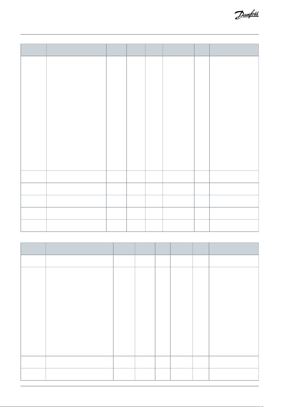
Index
Parameter
Min
Max
Unit
Default
ID
Description
P3.12.2.5
Setpoint source 1 selection
0
161332
0 = Not used
1 = Keypad setpoint 1
2 = Keypad setpoint 2
3 = AI1
4 = AI2
5 = AI3
6 = AI4
7 = AI5
8 = AI6
9 = ProcessDataIn1
10 = ProcessDataIn2
11 = ProcessDataIn3
12 = ProcessDataIn4
13 = ProcessDataIn5
14 = ProcessDataIn6
15 = ProcessDataIn7
16 = ProcessDataIn8
P3.12.2.6
Setpoint 1 minimum
-200.00
200.00
%
0.00
1069
P3.12.2.7
Setpoint 1 maximum
-200.00
200.00
%
100.00
1070
P3.12.2.8
Setpoint source 2 selection
0222
431
See P3.12.2.5.
P3.12.2.9
Setpoint 2 minimum
-200.00
200.00
%
0.00
1073
See P3.12.2.6.
P3.12.2.10
Setpoint 2 maximum
-200.00
200.00
%
100.00
1074
See P3.12.2.7.
Index
Parameter
Min
Max
Unit
Default
ID
Description
P3.12.3.1
Feedback Function Gain
-2100.0
2100.0
%
100.0
1058
P3.12.3.2
Feedback 1 Source Selection
0
142334
0 = Not used
1 = AI1
2 = AI2
3 = AI3 4 = AI4
5 = AI5 6 = AI6
7 = ProcessDataIn1
8 = ProcessDataIn2
9 = ProcessDataIn3
10 = ProcessDataIn4
11 = ProcessDataIn5
12 = ProcessDataIn6
13 = ProcessDataIn7
14 = ProcessDataIn8
P3.12.3.3
Feedback 1 Minimum
-200.00
200.00
%
0.00
336
P3.12.3.4
Feedback 1 Maximum
-200.00
200.00
%
100.00
337
VACON® 3000
Application Guide
INU Application
Table 79: Feedback Settings
AB319735759636en-000101 / DPD0182274 | Danfoss A/S © 2021.09

Index
Parameter
Min
Max
Unit
Default
ID
Description
P3.12.4.1
SP1 Sleep Frequency
0.00
320.00
Hz
0.00
1016
P3.12.4.2
SP1 Sleep Delay
0
300s0
1017
P3.12.4.3
SP1 Wake-up Level
%
0.0000
1018
P3.12.4.4
SP2 Sleep Frequency
0.00
320.00
Hz
0.00
1075
See P3.12.4.1.
P3.12.4.5
SP2 Sleep Delay
0
3000s0
1076
See P3.12.4.2.
P3.12.4.6
SP2 Wake-up Level
%
0.0000
1077
See P3.12.4.3.
Index
Parameter
Min
Max
Unit
Default
ID
Description
P3.13.1
Motor Preheat Function
040
1225
0 = Not used
1 = Always in stop state
2 = Controlled by DI
3 = Temperature limit
4 = Temperature limit (Measured motor temper-
ature)
P3.13.2
Preheat Temperature
Limit
-20
100°C0
1226
P3.13.3
Motor Preheat Current
0
31048
A01227
P3.13.4
Motor Preheat ON
Varies
Varies
DigIN
Slot0.1
1044
OPEN = No action
CLOSED = Preheat activated in Stop state
P3.13.5
Preheat Motor Temperature
030
1045
0 = Not used
1 = Temperature Input 1
2 = Temperature Input 2
3 = Temperature Input 3
Index
Parameter
Min
Max
Unit
Default
ID
Description
P3.14.1
Brake Control
020
1541
0 = Disabled
1 = Enabled
2 = Enabled with brake status super-
vision
P3.14.2
Brake Mechanical Delay
0.00
60.00
s
0.00
1544
VACON® 3000
Application Guide
Table 80: Sleep Function Settings
4.5.13 Group 3.13: Motor Preheat Parameters
Table 81: Motor Preheat Parameters
INU Application
4.5.14 Group 3.14: Mechanical Brake
Table 82: Mechanical Brake Parameters
AB319735759636en-000101 / DPD01822 | 75Danfoss A/S © 2021.09

Index
Parameter
Min
Max
Unit
Default
ID
Description
P3.14.3
Brake Opening Frequency Limit
0
P3.3.1.2
Hz
2.00
1535
P3.14.4
Brake Closing Frequency Limit
0
P3.3.1.2
Hz
2.00
1539
P3.14.5
Brake Current Limit
0.0
Varies
A
0.0
1085
P3.14.6
Brake Fault Delay
0.00
60.00
s
2.00
352
P3.14.7
Response to Brake Fault
030
1316
0 = No action
1 = Alarm
2 = Fault (Stop according to stop
mode)
3 = Fault (Stop by coasting)
P3.14.8
Brake Feedback
DigIN Slot0.1
1210
Index
Parameter
Min
Max
Unit
Default
ID
Description
P3.15.2
Encoder Repeat Channel
010
3001
0 = Channel A
1 = Channel B
P3.15.3
Encoder Advanced Control Word
0
3003
b0 = Encoder A fallback during error timeout
b1 = Encoder A no action with fallback
b2 = Encoder A fault rather than fallback
during startup
M3.15.4
Channel A
See Table 84.
M3.15.5
Channel B
See Table 85.
Index
Parameter
Min
Max
Unit
Default
ID
Description
P3.15.4.1
Input Control
0
25503010
1 = Input A: Single Ended Signaling
2 = Input A: Active Low Signaling
4 = Input B: Single Ended Signaling
8 = Input B: Active Low Signaling
16 = Input Z: Single Ended Signaling
32 = Input Z: Active Low Signaling
64 = Input M: Single Ended Signal-
ing
128 = Input M: Active Low Signaling
P3.15.4.2
Input AB Swap
010
3011
0 = No
1 = Yes
VACON® 3000
Application Guide
4.5.15 Group 3.15: Encoders
INU Application
Table 83: Encoder Parameters
Table 84: Channel A Settings
AB319735759636en-000101 / DPD0182276 | Danfoss A/S © 2021.09
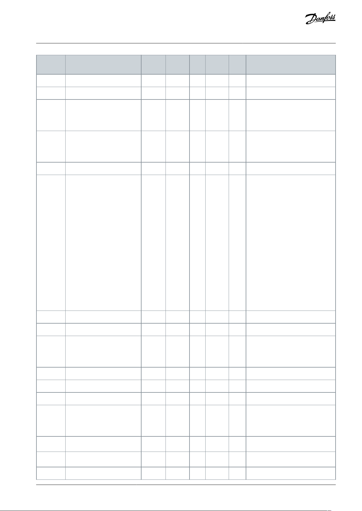
Index
Parameter
Min
Max
Unit
Default
ID
Description
P3.15.4.3
Encoder Debounce Time
0
3400ns250
3012
P3.15.4.4
Marker Debounce Time
0
3400ns250
3013
P3.15.4.5
Marker Event Mode
020
3014
0 = Input M Rising Edge
1 = Input M, Gated by Z
2 = Input Z Rising Edge
P3.15.4.6
Encoder Mode
030
3015
0 = Quadrature Mode
1 = Directional Pulse Mode
3 = Pulse + Direction Mode
P3.15.4.7
Resolution Prescale
1160
3016
P3.15.4.8
Hysteresis Filter Prescale
0140
3017
Prescaler:
0 = /2
1 = /4
2 = /8
3 = /16
4 = /32
5 = /64
6 = /128
7 = /256
8 = /512
9 = /1024
10 = /2048
11 = /4096
12 = /8192
13 = /16384
14 = /32768
P3.15.4.9
Encoder Resolution
0
524288
2048
3018
P3.15.4.10
Motor Pole Pairs
0
25523019
P3.15.4.11
Offset Mode
020
3020
0 = Manual Offset
1 = Auto upon first Z pulse
2 = Auto upon first M pulse
P3.15.4.12
Manual Offset
-524288
524288
deg03021
P3.15.4.13
Filter Time Constant
0.00
1000.00
ms
0.00
3022
P3.15.4.14
Frequency monitor A timeout
0.0
10000.0
ms
20.0
3024
P3.15.4.15
Frequency monitor A response
022
3025
0 = Issue fault
1 = Fallback to alternate encoder
2 = Fallback to sensorless operation
P3.15.4.16
HW Glitch Filter Time
0
3027
0 = HW error disabled
P3.15.4.17
SW Detection Limit
Hz
0.000
3028
0 = SW error disabled
P3.15.4.18
Encoder Repeated Error Limit
ms
0.0
3029
VACON® 3000
Application Guide
INU Application
AB319735759636en-000101 / DPD01822 | 77Danfoss A/S © 2021.09

Index
Parameter
Min
Max
Unit
Default
ID
Description
P3.15.5.1
Input Control
0
25503030
1 = Input A: Single Ended Signaling
2 = Input A: Active Low Signaling
4 = Input B: Single Ended Signaling
8 = Input B: Active Low Signaling
16 = Input Z: Single Ended Signaling
32 = Input Z: Active Low Signaling
64 = Input M: Single Ended Signaling
128 = Input M: Active Low Signaling
P3.15.5.2
Input AB Swap
010
3031
0 = No
1 = Yes
P3.15.5.3
Encoder Debounce Time
0
3400ns250
3032
P3.15.5.4
Marker Debounce Time
0
3400ns250
3033
P3.15.5.5
Marker Event Mode
020
3034
0 = Input M Rising Edge
1 = Input M, Gated by Z
2 = Input Z Rising Edge
P3.15.5.6
Encoder Mode
030
3035
0 = Quadrature Mode
1 = Directional Pulse Mode
3 = Pulse + Direction Mode
P3.15.5.7
Resolution Prescale
1160
3036
P3.15.5.8
Hysteresis Filter Prescale
0140
3037
Prescaler:
0 = /2
1 = /4
2 = /8
3 = /16
4 = /32
5 = /64
6 = /128
7 = /256
8 = /512
9 = /1024
10 = /2048
11 = /4096
12 = /8192
13 = /16384
14 = /32768
P3.15.5.9
Encoder Resolution
0
524288
2048
3038
P3.15.5.10
Motor Pole Pairs
0
25523039
P3.15.5.11
Offset Mode
020
3040
0 = Manual Offset
1 = Auto upon first Z pulse
2 = Auto upon first M pulse
VACON® 3000
Application Guide
Table 85: Channel B Settings
INU Application
AB319735759636en-000101 / DPD0182278 | Danfoss A/S © 2021.09

Index
Parameter
Min
Max
Unit
Default
ID
Description
P3.15.5.12
Manual Offset
-524288
524288
deg03041
P3.15.5.13
Filter Time Constant
0.00
1000.00
ms
0.00
3042
P3.15.5.14
Frequency monitor B timeout
0.0
10000.0
ms
0.0
3044
P3.15.5.15
Frequency monitor B response
020
3045
0 = Issue fault
1 = Fallback to alternate encoder
2 = Fallback to sensorless operation
Index
Parameter
Min
Max
Unit
Default
ID
Description
P3.17.1.1
MV star relay configuration
0
3403
P3.17.1.2
Aux 1A relay configuration
0
3407
Index
Parameter
Min
Max
Unit
Default
ID
Description
P3.17.2.1.1
PCC Interlock
DigIN Slot0.1
3315
P3.17.2.1.2
Enable PC feedback MVS DIN1
Disabled
3400
P3.17.2.1.3
Enable MX feedback MVS DIN2
Disabled
3401
P3.17.2.1.4
Enable KMX feedback MVS DIN3
Disabled
3402
P3.17.2.1.5
Aux14 KPC feedback configuration
0
3404
P3.17.2.1.6
Aux14 MX feedback configuration
0
3405
P3.17.2.1.7
Aux14 KMX feedback configuration
0
3406
Index
Parameter
Min
Max
Unit
Default
ID
Description
P3.17.2.2.1
Power on
DigIN Slot0.1
3550
P3.17.2.2.2
Power off
DigIN Slot0.1
3551
P3.17.2.2.3
Reset power on state
DigIN Slot0.1
3552
P3.17.2.2.4
Arc Fault Relay Online
DigIN Slot0.2
3607
P3.17.2.2.5
Arc Fault Relay Fault
DigIN Slot0.1
3608
P3.17.2.2.6
Door Safety Interlock
DigIN Slot0.2
3609
P3.17.2.2.7
GSW Unlock
DigIN Slot0.1
3553
P3.17.2.2.8
DC choke overtemperature 1
DigIN Slot0.2
3600
P3.17.2.2.9
DC choke overtemperature 2
DigIN Slot0.2
3601
P3.17.2.2.10
DC capacitor overpressure 1
DigIN Slot0.2
3602
VACON® 3000
Application Guide
4.5.16 Group 3.17: Precharge
Table 86: Digital Output Parameters
INU Application
Table 87: Digital Input Common Parameters
Table 88: Digital Input Internal Control Parameters
AB319735759636en-000101 / DPD01822 | 79Danfoss A/S © 2021.09

Index
Parameter
Min
Max
Unit
Default
ID
Description
P3.17.2.2.11
DC capacitor overpressure 2
DigIN Slot0.2
3603
P3.17.2.2.12
DC capacitor overpressure 3
DigIN Slot0.2
3604
P3.17.2.2.13
DC capacitor overpressure 4
DigIN Slot0.2
3605
P3.17.2.2.14
GSW open 1
DigIN Slot0.2
3610
P3.17.2.2.15
GSW open 2
DigIN Slot0.2
3611
P3.17.2.2.16
GSW open 3
DigIN Slot0.2
3612
P3.17.2.2.17
GSW open 4
DigIN Slot0.2
3613
P3.17.2.2.18
GSW closed 1
DigIN Slot0.2
3614
P3.17.2.2.19
GSW closed 2
DigIN Slot0.2
3615
P3.17.2.2.20
GSW closed 3
DigIN Slot0.2
3616
P3.17.2.2.21
GSW closed 4
DigIN Slot0.2
3617
P3.17.2.2.22
Interlock NC 1
DigIN Slot0.2
3624
P3.17.2.2.23
Interlock NC 2
DigIN Slot0.2
3625
P3.17.2.2.24
Interlock NC 3
DigIN Slot0.2
3626
P3.17.2.2.25
Interlock NC 4
DigIN Slot0.2
3627
P3.17.2.2.26
Interlock NO 1
DigIN Slot0.1
3628
P3.17.2.2.27
Interlock NO 2
DigIN Slot0.1
3629
P3.17.2.2.28
Interlock NO 3
DigIN Slot0.1
3630
P3.17.2.2.29
Interlock NO 4
DigIN Slot0.1
3631
P3.17.2.2.30
Enc HX breaker status 1
DigIN Slot0.2
3632
P3.17.2.2.31
Enc HX breaker status 2
DigIN Slot0.2
3633
P3.17.2.2.32
Enc HX breaker status 3
DigIN Slot0.2
3634
P3.17.2.2.33
Enc HX breaker status 4
DigIN Slot0.2
3635
P3.17.2.2.34
Temperature control breaker status 1
DigIN Slot0.2
3636
P3.17.2.2.35
Temperature control breaker status 2
DigIN Slot0.2
3637
P3.17.2.2.36
Temperature control breaker status 3
DigIN Slot0.2
3638
P3.17.2.2.37
Temperature control breaker status 4
DigIN Slot0.2
3639
P3.17.2.2.38
Cab HX status 1
DigIN Slot0.2
3640
P3.17.2.2.39
Cab HX status 2
DigIN Slot0.2
3641
P3.17.2.2.40
Cab HX status 3
DigIN Slot0.2
3642
P3.17.2.2.41
Cab HX status 4
DigIN Slot0.2
3643
P3.17.2.2.42
LD system OK 1
DigIN Slot0.2
3644
VACON® 3000
Application Guide
INU Application
AB319735759636en-000101 / DPD0182280 | Danfoss A/S © 2021.09
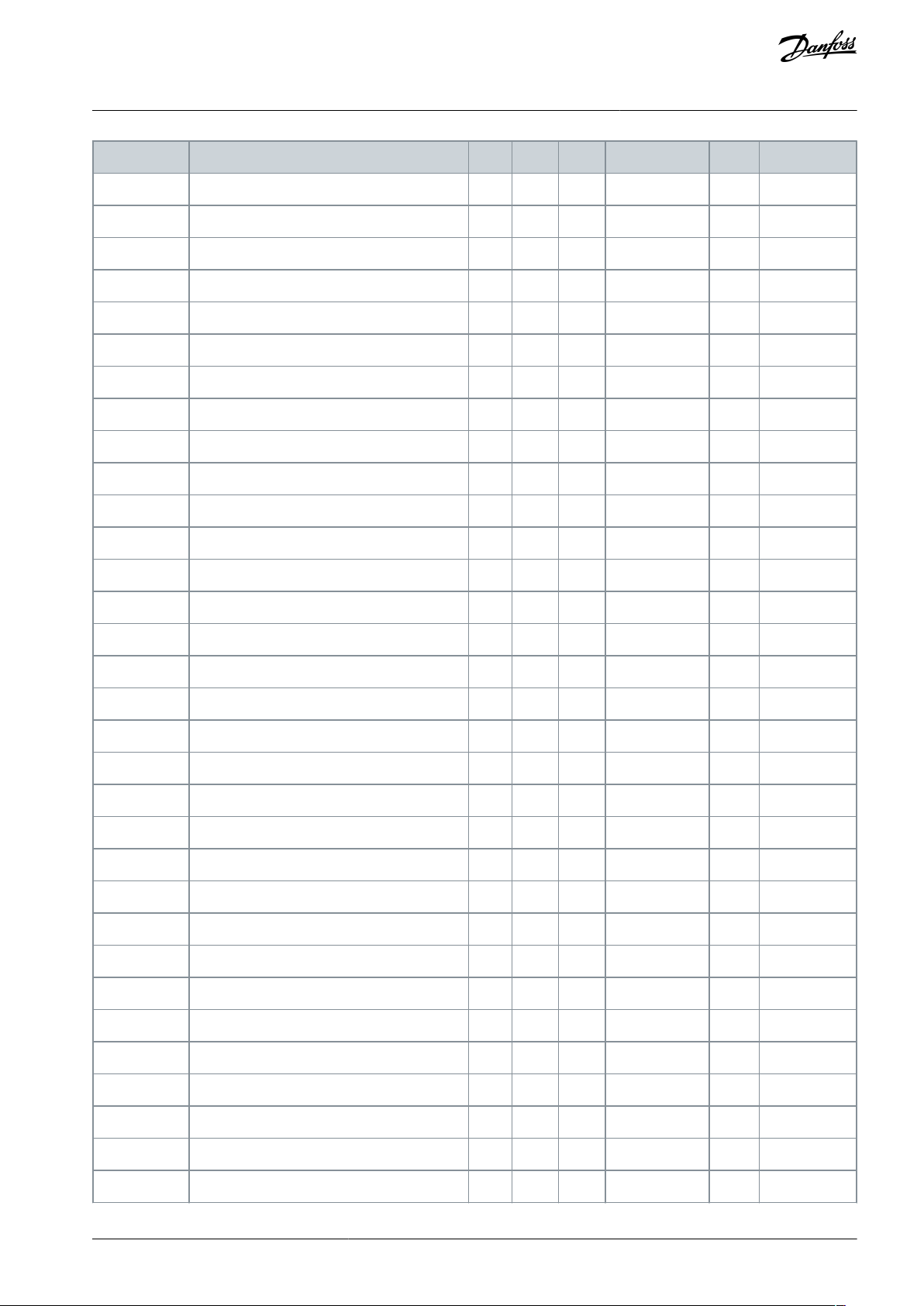
Index
Parameter
Min
Max
Unit
Default
ID
Description
P3.17.2.2.43
LD system OK 2
DigIN Slot0.2
3645
P3.17.2.2.44
LD system OK 3
DigIN Slot0.2
3646
P3.17.2.2.45
LD system OK 4
DigIN Slot0.2
3647
P3.17.2.2.46
LD no leak 1
DigIN Slot0.2
3648
P3.17.2.2.47
LD no leak 2
DigIN Slot0.2
3649
P3.17.2.2.48
LD no leak 3
DigIN Slot0.2
3650
P3.17.2.2.49
LD no leak 4
DigIN Slot0.2
3651
P3.17.2.2.50
Hex fan status 1.1
DigIN Slot0.2
3656
P3.17.2.2.51
Hex fan status 1.2
DigIN Slot0.2
3657
P3.17.2.2.52
Hex fan status 1.3
DigIN Slot0.2
3658
P3.17.2.2.53
Hex fan status 2.1
DigIN Slot0.2
3659
P3.17.2.2.54
Hex fan status 2.2
DigIN Slot0.2
3660
P3.17.2.2.55
Hex fan status 2.3
DigIN Slot0.2
3661
P3.17.2.2.56
Hex fan status 3.1
DigIN Slot0.2
3662
P3.17.2.2.57
Hex fan status 3.2
DigIN Slot0.2
3663
P3.17.2.2.58
Hex fan status 3.3
DigIN Slot0.2
3664
P3.17.2.2.59
Hex fan status 4.1
DigIN Slot0.2
3665
P3.17.2.2.60
Hex fan status 4.2
DigIN Slot0.2
3666
P3.17.2.2.61
Hex fan status 4.3
DigIN Slot0.2
3667
P3.17.2.2.62
Cooling Monitor 1
DigIN Slot0.2
3670
P3.17.2.2.63
Cooling Monitor 2
DigIN Slot0.2
3671
P3.17.2.2.64
Cooling Monitor 3
DigIN Slot0.2
3672
P3.17.2.2.65
Cooling Monitor 4
DigIN Slot0.2
3673
P3.17.2.2.66
Enclosure Humidity, Temp Status Invert
0
3736
P3.17.2.2.67
Enclosure Humidity Status 1
DigIN Slot0.2
3720
P3.17.2.2.68
Enclosure Humidity Status 2
DigIN Slot0.2
3721
P3.17.2.2.69
Enclosure Humidity Status 3
DigIN Slot0.2
3722
P3.17.2.2.70
Enclosure Humidity Status 4
DigIN Slot0.2
3723
P3.17.2.2.71
Enclosure Temperature Status 1.1
DigIN Slot0.2
3724
P3.17.2.2.72
Enclosure Temperature Status 1.2
DigIN Slot0.2
3725
P3.17.2.2.73
Enclosure Temperature Status 1.3
DigIN Slot0.2
3726
P3.17.2.2.74
Enclosure Temperature Status 2.1
DigIN Slot0.2
3727
VACON® 3000
Application Guide
INU Application
AB319735759636en-000101 / DPD01822 | 81Danfoss A/S © 2021.09

Index
Parameter
Min
Max
Unit
Default
ID
Description
P3.17.2.2.75
Enclosure Temperature Status 2.2
DigIN Slot0.2
3728
P3.17.2.2.76
Enclosure Temperature Status 2.3
DigIN Slot0.2
3729
P3.17.2.2.77
Enclosure Temperature Status 3.1
DigIN Slot0.2
3730
P3.17.2.2.78
Enclosure Temperature Status 3.2
DigIN Slot0.2
3731
P3.17.2.2.79
Enclosure Temperature Status 3.3
DigIN Slot0.2
3732
P3.17.2.2.80
Enclosure Temperature Status 4.1
DigIN Slot0.2
3733
P3.17.2.2.81
Enclosure Temperature Status 4.2
DigIN Slot0.2
3734
P3.17.2.2.82
Enclosure Temperature Status 4.3
DigIN Slot0.2
3735
Index
Parameter
Min
Max
Unit
Default
ID
Description
P3.17.3.1
Nom DC Precharge Voltage
5784.4
7862.0
V
0.0
3321
P3.17.3.2
Min DC Precharge Voltage
0.0
6800.9
V
0.0
3322
P3.17.3.3
Precharge Restart Limit
0.0
5784.4
V
500.0
3323
P3.17.3.4
Max DC Slew Rate
0.0
8000.0
V/s
0.0
3324
P3.17.3.5
Min DC Slew Rate
0.0
8000.0
V/s
0.0
3325
Index
Parameter
Min
Max
Unit
Default
ID
Description
P3.17.4.1
Fault Clear Timeout
0.00
300.00
s
0.00
3330
P3.17.4.2
MX Open Timeout
0.00
5.00s0.00
3331
P3.17.4.3
MX Close Timeout
0.00
5.00s0.00
3332
P3.17.4.4
KMX Open Timeout
0.00
5.00s0.00
3333
P3.17.4.5
KMX Close Timeout
0.00
5.00s0.00
3334
P3.17.4.6
KPC Open Timeout
0.00
5.00s0.00
3335
P3.17.4.7
Min Slew Rate Timeout
0.00
30.00
s
0.00
3336
P3.17.4.8
DC Discharge Timeout
0.00
600.00
s
0.00
3337
P3.17.4.9
DC Precharge Timeout
0.00
60.00
s
0.00
3338
P3.17.4.10
Activate Timeout
0.00
60.00
s
0.00
3339
P3.17.4.11
KPC Close Timeout
s
1.00
3342
P3.17.4.12
Cooling Off Delay
s
300.00
3343
P3.17.4.13
Cooling OK Timeout
s
15.00
3344
P3.17.4.14
Breaker close pulse time
s
0.08
3345
P3.17.4.15
Breaker open pulse time
s
0.08
3346
VACON® 3000
Application Guide
Table 89: Limits Parameters
INU Application
Table 90: Timeouts parameters
AB319735759636en-000101 / DPD0182282 | Danfoss A/S © 2021.09

Index
Parameter
Min
Max
Unit
Default
ID
Description
P3.17.5.1
Precharge Master
010
3351
0 = No
1 = Yes
P3.17.5.2
Start Request Mode
010
3352
0 = Implicit
1 = Explicit
P3.17.5.3
Commissioning Test Mode
010
3353
0 = Disabled
1 = Enabled
P3.17.5.4
Test Mode - Disable MX
010
3354
0 = Disabled
1 = Enabled
Index
Parameter
Min
Max
Unit
Default
ID
Description
V4.4.1
Energy Counter
Varies
2291
The quantity of energy taken from the supply network. The counter cannot be reset.
V4.4.3
Operating Time
a d hh:min
2298
The operating time of the control unit.
V4.4.7
Run Time
a d hh:min
2293
The motor run time.
V4.4.11
Power On Time
a d hh:min
2294
The quantity of time that the power unit has been
powered on. The counter cannot be reset.
V4.4.15
Start Command
Counter
2295
The number of times that the power unit has been
started.
VACON® 3000
Application Guide
Table 91: Switches Parameters
4.6 Diagnostics Menu
4.6.1 Counters
INU Application
4.6.1.1 Total Counters
Table 92: The Total Counter Parameters in the Diagnostics Menu
AB319735759636en-000101 / DPD01822 | 83Danfoss A/S © 2021.09

•
Index
Parameter
Min
Max
Unit
Default
ID
Description
P4.5.1
Energy Trip
Counter
Varies
2296
This counter can be reset:
Push [OK]. A Reset counter page shows. Push [OK]
again.
P4.5.3
Operating
Time
a d hh:min
2299
This counter can be reset. See instructions in P4.5.1 above.
Index
Parameter
Min
Max
Unit
Default
ID
Description
V4.6.1
Software Package
2524
The code for the software identification
V4.6.4
System Load
0
100%2300
The load on the control unit CPU
V4.6.5
Application Name
2525
The name of the application
V4.6.6
Application ID
837
The code of the application
V4.6.7
Application Version
838
V4.6.8
Language Selections
Selected language package in software loading
V4.6.9
Keypad Software Version
Index
Parameter
Min
Max
Unit
Default
ID
Description
V4.7.1
Power Size
Index
Parameter
Min
Max
Unit
Default
ID
Description
V4.8.1
Control Unit
2540
Status of the control unit
V4.8.2
UNIT1
2541
Status of the power unit
V4.8.3–19
UNIT2–29
Defined based on connected power units
Status of the power unit
VACON® 3000
Application Guide
4.6.1.2 Trip Counters
Table 93: The Trip Counter Parameters in the Diagnostics Menu
4.6.2 Software Info
Table 94: The Software Info Parameters in the Diagnostics Menu
INU Application
4.6.3 Drive Info
Table 95: The Drive Info Parameters in the Diagnostics Menu
4.6.4 Unit Status
Table 96: The Unit Status Parameters in the Diagnostics Menu
AB319735759636en-000101 / DPD0182284 | Danfoss A/S © 2021.09

Index
Parameter
Min
Max
Unit
Default
ID
Description
V5.1.1
Digital Input 1
010
2502
Status of the digital input signal
V5.1.2
Digital Input 2
010
2503
Status of the digital input signal
V5.1.3
Digital Input 3
010
2504
Status of the digital input signal
V5.1.4
Digital Input 4
010
2505
Status of the digital input signal
V5.1.5
Digital Input 5
010
2506
Status of the digital input signal
V5.1.6
Digital Input 6
010
2507
Status of the digital input signal
V5.1.7
Analog Input 1 Mode
133
2508
Shows the mode that is set for the analog input signal.
The selection is made with a DIP switch on the control
board.
1 = 0...20mA
3 = 0...10V
V5.1.8
Analog Input 1
0
100%0.00
2509
Status of the analog input signal
V5.1.9
Analog Input 2 Mode
133
2510
Shows the mode that is set for the analog input signal.
The selection is made with a DIP switch on the control
board.
1 = 0...20mA
3 = 0...10V
V5.1.10
Analog Input 2
0
100%0.00
2511
Status of the analog input signal
V5.1.11
Analog Output 1
Mode
131
2512
Shows the mode that is set for the analog input signal.
The selection is made with a DIP switch on the control
board.
1 = 0...20mA
3 = 0...10V
V5.1.12
Analog Output 1
0
100%0.00
2513
Status of the analog output signal
V5.1.13
Relay Output 1
010
2514
Status of the relay output signal
V5.1.14
Relay Output 2
010
2515
Status of the relay output signal
V5.1.15
Relay Output 3
010
2516
Status of the relay output signal
VACON® 3000
Application Guide
4.7 I/O and Hardware Menu
4.7.1 Basic I/O
Table 97: The Basic I/O Parameters in the I/O and Hardware Menu
INU Application
4.7.2 Option Board Slots
The parameters in this menu are different for all the option boards. The parameters of the installed option board is shown. If there is
no option board in the slots C, D or E, no parameters are shown. See more about the location of the slots in chapter 3.1 General
Information on the Programming.
When an option board is removed, the fault code 39 and the fault name Device removed show on the display.
AB319735759636en-000101 / DPD01822 | 85Danfoss A/S © 2021.09

Menu
Function
Description
Slot C
Settings
The settings that are related to the option board.
Monitoring
Monitor the data that is related to the option board.
Slot D
Settings
The settings that are related to the option board.
Monitoring
Monitor the data that is related to the option board.
Slot E
Settings
The settings that are related to the option board.
Monitoring
Monitor the data that is related to the option board.
Index
Parameter
Min
Max
Unit
Default
ID
Description
V5.5.1
Battery State
132205
Status of the battery.
1 = Not installed
2 = Installed
3 = Replace the battery
P5.5.2
Time
hh:mm:ss
2201
The current time of the day
P5.5.3
Date
dd.mm.
2202
The current date
P5.5.4
Year
yyyy
2203
The current year
P5.5.5
Daylight Saving
142204
The daylight saving rule
1 = Off
2 = EU: starts on the last Sunday in March, ends on the last
Sunday in October
3 = US: starts on the 2nd Sunday in March, ends on the 1st
Sunday in November
4 = Russia (permanent)
P5.5.6
Time Offset
2614
Index
Parameter
Min
Max
Unit
Default
ID
Description
V5.5.7.1.1
SNTP Mode
3162
V5.5.7.1.2
Server 1 IP
3163
V5.5.7.1.3
Server 2 IP
3164
V5.5.7.1.4
SNTP Port
3165
V5.5.7.1.5
Time Interval
3166
VACON® 3000
Application Guide
Table 98: Option Board Related Parameters
4.7.3 Real-time Clock
Table 99: The Real-time Clock Parameters in the I/O and Hardware Menu
INU Application
4.7.4 Simple Network Time Protocol (SNTP)
The simple network time protocol (SNTP) allows devices connected to a TCP/IP network receive precise time information from designated time servers. The time information can be received either by the client device polling the time servers or the time servers
broadcasting the time.
Table 100: SNTP Settings
AB319735759636en-000101 / DPD0182286 | Danfoss A/S © 2021.09

Index
Parameter
Min
Max
Unit
Default
ID
Description
V5.5.7.2.1
SNTP status
3167
V5.5.7.2.2
Server IP
3168
V5.5.7.2.3
Last update time
3169
Index
Parameter
Min
Max
Unit
Default
ID
Description
P5.6.1.1
Fan Control Mode
011
2377
0 = Always on
1 = Optimised
V5.6.1.5
Fan Lifetime ID
849
Lifetime of the fan of the drive
P5.6.1.6
Fan lifetime alarm
limit
0
200000
h
50000
824
Alarm limit of the fan lifetime
B5.6.1.7
Fan lifetime reset ID
823
Reset the fan lifetime counter with this button.
P5.6.4.8
Belt count
0
6000
Number of phase module belts connected to the
control unit.
P5.6.4.9
AUX Chain Unit Count
0
6001
Number of auxiliary connections to the control unit,
for example, auxiliary I/O boards, DFE, or CCA board.
P5.6.5.1
Sine Filter
010
2527
0 = Disabled
1 = Enabled
P5.6.6.1
Harmonic Filter
010
2497
0 = Disabled
1 = Enabled
Index
Parameter
Min
Max
Unit
Default
ID
Description
P5.7.1
Timeout
Time
060min0804
The time after which the display goes back to the page that is set
with parameter P5.7.2.
0 = Not used
P5.7.2
Default
Page
040
2318
The page that the display shows when the drive is powered up, or
when the time that is set with P5.7.1 is expired. If the value is set to
0, the display shows the last page that it showed.
0 = None
1 = A menu index
VACON® 3000
Application Guide
Table 101: SNTP Monitoring
INU Application
4.7.5 Power Unit Settings
This menu contains the settings of the fan, the sine-wave filter, and the harmonic filter.
The fan operates in the optimized or the always on mode. In the optimized mode, the internal logic of the drive receives data about
the temperature and controls the fan speed. After the drive goes in the Ready state, the fan stops in 5 minutes. In the always on
mode, the fan operates in full speed, and does not stop.
The sine-wave filter keeps the overmodulation depth in limits and does not let the thermal management functions decrease the
switching frequency.
The harmonic filter can be enabled to avoid possible resonances in the DC link of the AC drive.
Table 102: Power Unit Settings
4.7.6 Keypad
Table 103: The Keypad Parameters in the I/O and Hardware Menu
AB319735759636en-000101 / DPD01822 | 87Danfoss A/S © 2021.09

Index
Parameter
Min
Max
Unit
Default
ID
Description
2 = Main menu
3 = Control page
4 = Multimonitor
P5.7.3
Menu Index
2499
Set a page to be the menu index. (The selection 1 in P5.7.2.)
P5.7.4
Contrast
3070%50830
Set the contrast of the display.
P5.7.5
Backlight
Time
060min5818
Set the time after which the backlight of the display turns off. If the
value is set to 0, the backlight is always on.
Submenu level 1
Submenu level 2
Submenu level 3
Submenu level 4
RS-485
Common settings
Protocol
Ethernet
Common settings
IP address mode
Duplicate IP detect
Speed/Duplex
Ethernet Fieldbus 1
Ethernet Fieldbus 2
Fixed IP
IP address
Subnet mask
Default gateway
Speed/Duplex
IP address
Subnet mask
Default gateway
MAC address
Packet rate
Peak packet rate
Modbus TCP
Common settings
Connection limit
Slave address
Communication timeout
IDMap
Monitoring
Control word
VACON® 3000
Application Guide
INU Application
4.7.7 Fieldbus
In the I/O and Hardware menu, there are the parameters that are related to fieldbus boards. You can find the instructions on how to
use these parameters in the related fieldbus manual.
Table 104: Fieldbus Menu Structure
AB319735759636en-000101 / DPD0182288 | Danfoss A/S © 2021.09

Submenu level 1
Submenu level 2
Submenu level 3
Submenu level 4
Status word
Drive speed reference
Drive speed actual
Connection 1
Monitoring
Connection 2
Monitoring
Connection 3
Monitoring
Index
Parameter
Min
Max
Unit
Default
ID
Description
P5.9.1.1
IP address mode
021
2482
0 = Fixed IP
1 = DHCP with AutoIP
2 = DCP
P5.9.1.2
Duplicate IP detection
011
2569
0 = Disabled
1 = Enabled
P5.9.1.3
Speed/duplex
040
2500
0 = Autonegotiation
1 = 10M HD
2 = 10M FD
3 = 100M HD
4 = 100M FD
P5.9.1.4
Ethernet Fieldbus 1
0
4
(1)
0
2622
2 Ethernet-based internal fieldbuses can be enabled
at a time. Select fieldbus from the list.
0 = None
1 = PROFINET I/O
2 = EtherNet/IP
3 = Modbus TCP
4 = BACnet/IP
P5.9.1.5
Ethernet Fieldbus 2
0
4
(1)
3
2623
M5.9.1.6
Fixed IP
See Table 106.
V5.9.1.7
Speed/duplex
04V5.9.1.8
IP address
0
255
VACON® 3000
Application Guide
INU Application
4.7.8 Fieldbus General
Enabling Ethernet Fieldbus Protocol
Needed internal Ethernet based fieldbus protocols can be enabled with parameters Ethernet Fieldbus 1 (ID 2622) and Ethernet Field-
bus 2 (ID 2623).
Both parameters contain the same list with “PROFINET I/O, EtherNet/IP, BACnet/IP and Modbus TCP” protocols. PROFINET I/O and
EtherNet/IP are visible only if included in the drive configuration. By default Modbus TCP is enabled, but if not used, it is recommended to turn it off.
If the same fieldbus is selected to both parameters, the fieldbus protocol is still activated only once. Protocol specific menu tree
becomes visible only after enabling it from these parameters. When using VACON® Live, to see protocol specific menus, the M5.9
Ethernet menu tree must be reloaded after enabling the protocols.
When restoring parameters from older firmware version, drive checks on start-up which protocols were enabled in old firmware and
sets up these new parameters accordingly. After having restored parameters, restart the drive. If more than two Ethernet fieldbuses
were activated in old firmware, new firmware allows it. In this case, these two new parameters show “None”, but when the values
are changed, all Ethernet fieldbuses are stopped, and only the enabled ones are started.
Table 105: Fieldbus Common Settings
AB319735759636en-000101 / DPD01822 | 89Danfoss A/S © 2021.09

Index
Parameter
Min
Max
Unit
Default
ID
Description
V5.9.1.9
Subnet mask
0
255
V5.9.1.10
Default gateway
0
255
V5.9.1.11
MAC address
V5.9.1.12
Packet rate
V5.9.1.13
Peak packet rate
Index
Parameter
Min
Max
Unit
Default
ID
Description
P5.9.1.6.1
IP address
2529
P5.9.1.6.2
Subnet mask
2530
P5.9.1.6.3
Default gateway
2531
Index
Parameter
Min
Max
Unit
Default
ID
Description
P5.13.1
Controlling Fieldbus
050
2539
0 = Automatic
1 = Slot E
2 = PROFINET I/O
3 = EtherNet/IP
4 = Modbus TCP
5 = BACnet/IP
V5.13.2
Controlling Fieldbus
052610
Index
Parameter
Min
Max
Unit
Default
ID
Description
P5.13.3.1
Redundancy Mode
020
2606
0 = Disabled
1 = Switch on failing
2 = Switch on faulted
P5.13.3.2
Primary Fieldbus Connection
0
2607
VACON® 3000
Application Guide
1
Depends on fieldbuses included in drive configuration
Table 106: Fixed IP
INU Application
Table 107: Fieldbus General
4.7.9 Fieldbus Redundancy
VACON® 3000 supports the usage of two fieldbus connections. The drive accepts control data only from the primary fieldbus. If the
primary fieldbus connection fails, the control can be automatically switched to a secondary fieldbus using the fieldbus redundancy
control. VACON® 3000 built-in fieldbus protocols support fieldbus redundancy control. The only exception is RS485 N2, which does
not support fieldbus redundancy. Recent firmware versions of fieldbus option boards also support fieldbus redundancy.
When switch on failing mode is selected, and the current fieldbus connection detects missing communication from the controller,
the switchover command is given to change to the other fieldbus connection. When switch on faulted mode is selected, and the
current fieldbus connection gets a timeout, the switchover command is given to change to the other fieldbus connection.
The switchback functionality forces a change back to the primary fieldbus connection when it is in operational state and when the
given time delay has elapsed. If the switchback functionality is deactivated, the switchover between the fieldbus connections is only
performed when the currently controlling fieldbus begins to fail or becomes faulted.
The currently controlling fieldbus protocol can be checked from the monitoring value V5.13.2 Controlling Fieldbus (ID 2610).
Table 108: Fieldbus Redundancy
AB319735759636en-000101 / DPD0182290 | Danfoss A/S © 2021.09

Index
Parameter
Min
Max
Unit
Default
ID
Description
P5.13.3.3
Secondary Fieldbus Connection
0
2608
P5.13.3.4
Switchover Timeout
0
65535
ms02609
P5.13.3.5
Switchback Timeout
0
65535
s102612
V5.13.3.6
Switchover Counter
2611
Index
Parameter
Min
Max
Unit
Default
ID
Description
V5.14.1.1
Board status
29001
V5.14.1.2
Breaker enable status
29002
V5.14.1.3
Breaker switch status
29003
V5.14.1.4
Measurement configuration
switch
29004
V5.14.1.5
Digital input 1–16
29005
V5.14.1.6
Digital input 17–32
29006
V5.14.1.7
DigOUT AUX 14
29015
V5.14.1.8
Analog input 1
0.00
100.00
%
0.00
29007
Status of the analog input signal
V5.14.1.9
Analog input 1 mode
29008
Shows the mode that is set for the analog
input signal. The selection is made with a
DIP switch on the board.
1 = 0...20 mA
3 = 0...10 V
V5.14.1.10
Analog input 2
0.00
100.00
%
0.00
29009
Status of the analog input signal
V5.14.1.11
Analog input 2 mode
29010
Shows the mode that is set for the analog
input signal. The selection is made with a
DIP switch on the board.
1 = 0...20 mA
3 = 0...10 V
V5.14.1.12
Analog input 3
0.00
100.00
%
0.00
29011
Status of the analog input signal
V5.14.1.13
Analog input 3 mode
29012
Shows the mode that is set for the analog
input signal. The selection is made with a
DIP switch on the board.
1 = 0...20 mA
3 = 0...10 V
V5.14.1.14
Analog input 4
0.00
100.00
%
0.00
29013
Status of the analog input signal
VACON® 3000
Application Guide
INU Application
4.7.10 Aux Chain
The contents of the menu depend on the units connected to the aux chain. The number of units is configured with parameter AUX
Chain Unit Count (ID 6001). The parameters in
unit has a similar menu and set of parameters (Aux 15, Aux 16, Aux 17).
Table 109: Aux 14 Parameters in the I/O and Hardware Menu
Table 97 are for the first unit connected to the Aux chain (Aux 14). Each connected
AB319735759636en-000101 / DPD01822 | 91Danfoss A/S © 2021.09
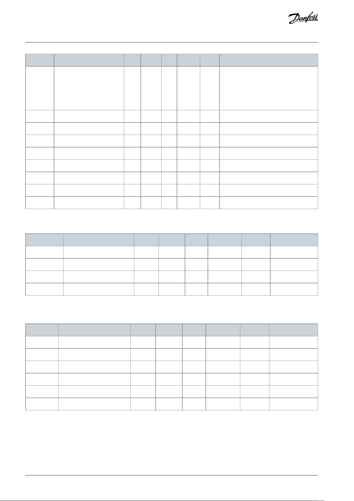
Index
Parameter
Min
Max
Unit
Default
ID
Description
V5.14.1.15
Analog input 4 mode
29014
Shows the mode that is set for the analog
input signal. The selection is made with a
DIP switch on the board.
1 = 0...20 mA
3 = 0...10 V
V5.14.1.16
Analog input 5
0.00
100.00
%
0.00
29015
V5.14.1.17
Analog input 5 mode
29016
V5.14.1.18
Analog input 6
0.00
100.00
%
0.00
29017
V5.14.1.19
Analog input 6 mode
29018
V5.14.1.20
Analog input 7
0.00
100.00
%
0.00
29019
V5.14.1.21
Analog input 7 mode
29020
V5.14.1.22
Board temperature
-20.0
100.0
0.0
29021
V5.14.1.23
Supply voltage
0.0
30.0
0.0
29022
Index
Parameter
Min
Max
Unit
Default
ID
Description
V5.14.3.1
Board status
29401
V5.14.3.2
Board temperature
-20.0
100.0
0.0
29423
V5.14.3.3
Unit temperature
-20.0
125.0
0.0
29425
V5.14.3.4
I/O
29426
Index
Parameter
Min
Max
Unit
Default
ID
Description
V5.15.1
Board status
28951
V5.15.2
Digital inputs
28955
V5.15.3
Digital outputs
28965
V5.15.4
Gated relays
28966
V5.15.5
Board temperature
-20.0
100.0
0.0
28923
V5.15.6
Supply voltage
0.0
30.0
0.0
28924
VACON® 3000
Application Guide
INU Application
The Unit 22 parameters are monitoring values for the DFE unit, which is only used in 12-pulse and 24-pulse drives.
Table 110: Unit 22 Parameters in the I/O and Hardware Menu
4.7.11 MV-star
Table 111: The MV-star Parameters in the I/O and Hardware Menu
AB319735759636en-000101 / DPD0182292 | Danfoss A/S © 2021.09

Index
Parameter
Min
Max
Unit
Default
ID
Description
P6.1
Language selection
Varies
Varies
Varies
802
The selection is different in all the language packages.
M6.5
Parameter backup
See 4.8.2 Parameter Backup Parameters.
M6.6
Parameter compare
See 4.8.3 Parameter Compare Parameters.
P6.7
Drive name
2528
Use VACON® Live PC tool to give a name to the drive if
necessary.
M6.8
Licenses
See 4.8.4 License Parameters.
Index
Parameter
Min
Max
Unit
Default
ID
Description
B6.5.1
Restore Factory Defaults
831
Restores the default parameter values and starts the Startup
wizard.
B6.5.4
Save to Set 1
2489
Keeps a customized parameter set (that is, all the parameters included in the application).
B6.5.5
Restore from Set 1
2490
Loads the customized parameter set to the drive.
B6.5.6
Save to Set 2
2491
Keeps another customized parameter set (that is, all the parameters included in the application).
B6.5.7
Restore from Set 2
2492
Loads the customized parameter set 2 to the drive.
Index
Parameter
Min
Max
Unit
Default
ID
Description
B6.6.1
Active set - Set 1
2493
B6.6.2
Active set - Set 2
2494
B6.6.3
Active set - Defaults
2495
B6.6.4
Active set - Keypad Set
2496
Index
Parameter
Min
Max
Unit
Default
ID
Description
P6.8.1
Insert License
Insert a drive-specific license to enable new features or remove added features.
VACON® 3000
Application Guide
4.8 User Settings
4.8.1 User Settings Parameters
Table 112: General Settings in the User Settings Menu
4.8.2 Parameter Backup Parameters
Table 113: The Parameter Backup Parameters in the User Settings menu
INU Application
4.8.3 Parameter Compare Parameters
Table 114: Parameter Compare Parameters in the User Settings Menu
4.8.4 License Parameters
Table 115: License Parameters in the User Settings Menu
AB319735759636en-000101 / DPD01822 | 93Danfoss A/S © 2021.09

Menu
Function
M1 Quick setup
Quick setup
M2 Monitor
Multimonitor
AFE monitor
I/O
Extras/Advanced
Maintenance counters
Fieldbus data
Precharge
M3 Parameters
Basic parameters
Control parameters
Precharge
Start/Stop setup
I/O Configuration
Fieldbus data mapping
Supervisions
Protections
Automatic reset
Application settings
Maintenance counters
M4 Diagnostics
Active faults
Reset faults
Fault history
Total counters
VACON® 3000
Application Guide
AFE Application
5 AFE Application
5.1 Overview
The AFE application is used to control the AFE phase modules of the VACON® 3000.
It is possible to control the drive from the control panel (keypad), Fieldbus, or I/O terminal.
It is possible to configure all the drive outputs freely. There is 1 analog output and 3 relay outputs (Run, Fault, Ready) available on
the basic I/O board.
5.2 Menu Structure
The data of the AC drive is in menus and submenus. To move between the menus, use the arrow buttons Up and Down in the
keypad. To go into a group or an item, push the [OK] button. To go back to the level where you were before, push the [BACK/RESET]
button.
On the display, you see your current location in the menu, for example M3.2.1. You also see the name of the group or item in your
current location.
Table 116: Menu Structure
AB319735759636en-000101 / DPD0182294 | Danfoss A/S © 2021.09

Menu
Function
Trip counters
Software info
Drive info
Unit status
M5 I/O and Hardware
Basic I/O
Slot C
Slot D
Slot E
Real-time clock
Power unit settings
RS485
Ethernet
Fieldbus general
Aux chain
MV-star
M6 User settings
Language selections
Parameter backup
Parameter compare
Drive name
Licenses
M7 Favorites
Favorites
Index
Parameter
Min
Max
Unit
Default
ID
Description
1.2
Grid voltage feedback mode
020
5020
0 = Source Voltage (pre-LCL)
1 = Shunt Capacitor Voltage
2 = PCC Voltage
1.3
Grid Voltage Feedback Channel A
0127
5021
0 = Ground/Reference
1 = AN Phase Voltage
2 = NA Phase Voltage
3 = BN Phase Voltage
4 = NB Phase Voltage
5 = CN Phase Voltage
6 = NC Phase Voltage
7 = AB Line Voltage
VACON® 3000
Application Guide
AFE Application
5.3 Quick Setup
Table 117: M1 Quick Setup
AB319735759636en-000101 / DPD01822 | 95Danfoss A/S © 2021.09

Index
Parameter
Min
Max
Unit
Default
ID
Description
8 = BA Line Voltage
9 = BC Line Voltage
10 = CB Line Voltage
11 = CA Line Voltage
12 = AC Line Voltage
1.4
Grid Voltage Feedback Channel B
0120
5022
See ID 5020 above
1.5
Grid Voltage Feedback Channel C
0129
5023
See ID 5020 above
1.6
Grid Voltage Feedback Scale
-10000.0
10000.0
120.0000
5024
1.7
Filter Topology
020
5030
1.8
Regen Filter Select
080
5039
0 = Special
1 = L20.3
2 = L20.3 HSI
3 = L20.4
4 = L20.4 HSI
5 = L30.3
6 = L30.3 HSI
7 = L30.4
8 = L30.4 HSI
1.9
Special Filter Index
21000
5040
Index
Monitoring value
Unit
Scale
ID
Description
M2.3.1
DC link
See Table 119.
M2.3.2
Line PLL
See Table 120.
M2.3.3
Line filter observer
See Table 121.
V2.3.5
Precharge state
1
3510
0 = Reset
1 = Failed
2 = Not Ready
3 = Ready
4 = Charging
5 = Synchronizing
6 = Contactor Close
7 = Stabilizing
8 = Operational
9 = Loaded
Index
Monitoring value
Unit
Scale
ID
Description
V2.3.1.1
DC-link voltage
V
0.1
7
VACON® 3000
Application Guide
AFE Application
5.4 Monitor Menu
5.4.1 AFE Monitor
Table 118: AFE Monitoring
Table 119: DC-Link Monitoring
AB319735759636en-000101 / DPD0182296 | Danfoss A/S © 2021.09

Index
Monitoring value
Unit
Scale
ID
Description
V2.3.2.1
Line voltage
V15510
V2.3.2.2
Line frequency
Hz
0.01
5511
V2.3.2.3
Line PLL locked
1
5512
0 = No
1 = Yes
Index
Monitoring value
Unit
Scale
ID
Description
V2.3.3.1
AFE Active Current
A
0.1
5513
V2.3.3.2
AFE Reactive Current
A
0.1
5514
V2.3.3.3
Grid Active Current
A
0.1
5515
V2.3.3.4
Grid Reactive Current
A
0.1
5516
V2.3.3.5
Cap Active Current
A
0.1
5517
V2.3.3.6
Cap Reactive Current
A
0.1
5518
V2.3.3.7
Cap Active Voltage
V
0.1
5519
V2.3.3.8
Cap Reactive Voltage
V
0.1
5520
V2.3.3.9
Grid Active Voltage
V
0.1
5521
V2.3.3.10
Grid Reactive Voltage
V
0.1
5522
V2.3.3.11
AFE output current
A
0.1
5530
Index
Monitoring value
Unit
Scale
ID
Description
V2.4.1
Slot A DIN 1, 2, 3
115V2.4.2
Slot A DIN 4, 5, 6
116V2.4.3
Slot B RO 1, 2, 3
117V2.4.4
Analog input 1
%
0.0059Slot A.1 as default.
V2.4.5
Analog input 2
%
0.0060Slot A.2 as default.
V2.4.6
Analog input 3
%
0.0061Slot D.1 as default.
V2.4.7
Analog input 4
%
0.0062Slot D.2 as default.
V2.4.8
Analog input 5
%
0.0075Slot E.1 as default.
V2.4.9
Analog input 6
%
0.0076Slot E.2 as default.
V2.4.10
Slot A AO1
%
0.0081V2.4.15
Analog input 7
%
0.00
5640
VACON® 3000
Application Guide
Table 120: Line PLL Monitoring
Table 121: Line Filter Observer
AFE Application
5.4.2 I/O Monitoring
Table 122: I/O Signal Monitoring
AB319735759636en-000101 / DPD01822 | 97Danfoss A/S © 2021.09

Index
Monitoring value
Unit
Scale
ID
Description
V2.4.16
Analog input 8
%
0.00
5641
V2.4.17
Analog input 9
%
0.00
5642
V2.4.18
Analog input 10
%
0.00
5643
Index
Monitoring value
Unit
Scale
ID
Description
V2.6.1
Drive Status Word
1
43
B1 = Ready
B2 = Run
B3 = Fault
B6 = Run Enable
B7 = Alarm Active
B10 = DC current in stop
B11 = DC brake active
B12 = Run Request
B13 = Regulator Active
V2.6.2
Ready status
1
78
B0 = Run Enable high
B1 = No fault active
B2 = Charge switch closed
B3 = DC voltage within limits
B4 = Power manager initialized
B5 = Power unit is not blocking start
B6 = System software is not blocking start
V2.6.3
Application Status Word1
1
89
B0 = Run Interlock 1
B1 = Run Interlock 2
B5 = I/O A control active
B7 = Fieldbus Control Active
B8 = Local control active
B9 = PC control active
B15 = Drive stopped from keypad
V2.6.4
DIN Status Word 1
156V2.6.5
DIN Status Word 2
157V2.6.6
Last active fault code
137V2.6.7
Last active fault ID
195V2.6.8
Last active alarm code
174V2.6.9
Last active alarm ID
194V2.6.12
Unit temperature
°C
0.18V2.6.13
MVS DIN Status Word
0
6043
V2.6.14
Enclosure Humidity and Temperature
0
3586
VACON® 3000
Application Guide
5.4.3 Extras and Advanced
Table 123: Monitoring of the Advanced Values
AFE Application
AB319735759636en-000101 / DPD0182298 | Danfoss A/S © 2021.09

Index
Monitoring value
Unit
Scale
ID
Description
V2.7.1
Maintenance Counter 1
h/kRev
Varies
1101
Index
Monitoring value
Unit
Scale
ID
Description
V2.8.1
FB Control Word
1
874
V2.8.2
FB status word
1
864
V2.8.3
FB Speed Reference
Hz
0.01
875
V2.8.4
FB Speed Actual
%
0.01
865
V2.8.5
FB general control word
1
861
V2.8.6
FB general status word
1
862
M2.8.7
Data In
See Table 126
M2.8.8
Data Out
See Table 127
Index
Monitoring value
Unit
Scale
ID
Description
V2.8.7.1
FB Data In 1
1
876
V2.8.7.2
FB Data In 2
1
877
V2.8.7.3
FB Data In 3
1
878
V2.8.7.4
FB Data In 4
1
879
V2.8.7.5
FB Data In 5
1
880
V2.8.7.6
FB Data In 6
1
881
V2.8.7.7
FB Data In 7
1
882
V2.8.7.8
FB Data In 8
1
883
V2.8.7.9
FB Data In 9
1
229
V2.8.7.10
FB Data In 10
1
230
V2.8.7.11
FB Data In 11
1
231
V2.8.7.12
FB Data In 12
1
232
V2.8.7.13
FB Data In 13
1
233
V2.8.7.14
FB Data In 14
1
234
V2.8.7.15
FB Data In 15
1
235
V2.8.7.16
FB Data In 16
1
236
VACON® 3000
Application Guide
5.4.4 Maintenance Counters
Table 124: Maintenance Counter Monitoring
5.4.5 Fieldbus Process Data Monitoring
Table 125: Fieldbus Process Data Monitoring
AFE Application
Table 126: Data In Monitoring
AB319735759636en-000101 / DPD01822 | 99Danfoss A/S © 2021.09

Index
Monitoring value
Unit
Scale
ID
Description
V2.8.8.1
FB Data Out 1
1
866
V2.8.8.2
FB Data Out 2
1
867
V2.8.8.3
FB Data Out 3
1
868
V2.8.8.4
FB Data Out 4
1
869
V2.8.8.5
FB Data Out 5
1
870
V2.8.8.6
FB Data Out 6
1
871
V2.8.8.7
FB Data Out 7
1
872
V2.8.8.8
FB Data Out 8
1
873
V2.8.8.9
FB Data Out 9
1
245
V2.8.8.10
FB Data Out 10
1
246
V2.8.8.11
FB Data Out 11
1
247
V2.8.8.12
FB Data Out 12
1
248
V2.8.8.13
FB Data Out 13
1
249
V2.8.8.14
FB Data Out 14
1
250
V2.8.8.15
FB Data Out 15
1
251
V2.8.8.16
FB Data Out 16
1
252
Index
Monitoring value
Unit
Scale
ID
Description
V2.10.1
Precharge state
1
3510
0 = Reset
1 = Failed
2 = Not Ready
3 = Ready
4 = Charging
5 = Synchronizing
6 = Contactor Close
7 = Stabilizing
8 = Operational
9 = Loaded
V2.10.2
Precharge inhibit
1
3511
V2.10.3
Precharge error flags
1
3568
b0 = Software
b1 = Main Pilot Open TO
b2 = Mx Open TO
b3 = PC Contactor Open TO
b4 = DC-link Discharge TO
b5 = Front End Fault Clear TO
b6 = DC-link Overvoltage
VACON® 3000
Application Guide
Table 127: Data Out Monitoring
AFE Application
5.4.6 Precharge Monitoring
Table 128: Precharge Monitoring Values
AB319735759636en-000101 / DPD01822100 | Danfoss A/S © 2021.09
 Loading...