

Operating Guide
VACON® 3000 Enclosed Drive
drives.danfoss.com


VACON® 3000 Enclosed Drive
Operating Guide
Contents
1
Introduction 9
1.1
Purpose of this Operating Guide 9
Additional Resources 9
1.2
Manual Version 9
1.3
Safety 10
2
Safety Symbols 10
2.1
Qualified Personnel 10
2.2
Danger and Warnings 10
2.3
Cautions and Notices 12
2.4
Main Circuit Breaker 14
2.5
Safety and Protection Requirements 14
2.5.1
Minimum Requirements for MCB and MCB Control 14
2.5.2
Contents
Product Overview 16
3
Intended Use 16
3.1
3.2
Product Description 16
3.2.1
AFE Drive 16
3.2.2
12-Pulse Drive 17
3.3
Type Code Description 17
3.4
Available Options 18
4
Receiving the Delivery 21
4.1
Checking the Delivery 21
4.2
Storage 21
4.3
Lifting and Moving the Enclosed Drive 21
5
Mechanical Installation 24
5.1
Operating Environment 24
5.2
Cabinet Installation 24
5.3
Dimensions of the Enclosed Drive 25
5.4
Liquid Cooling Requirements 26
5.4.1
Safety in Liquid-cooling 26
5.4.2
General Information on Liquid Cooling 26
5.4.3
Cooling Liquid 27
5.4.3.1
5.4.3.2
5.4.3.3
Quality Requirements for the Purified Water 27
Purified Water as Coolant 27
Antifreeze Mix as Coolant 27
AQ286660579921en-000101/DPD02033 | 3Danfoss A/S © 2021.09

VACON® 3000 Enclosed Drive
Operating Guide
5.4.3.4
5.4.3.5
5.4.4
Cooling System 30
5.4.4.1
5.4.4.2
5.4.4.3
5.5
Cooling and Free Space Around the Enclosed Drive 32
6
Electrical Installation 34
6.1
Galvanic Isolation Between the MV and LV Sections 34
6.2
Mains and Motor Cable Selection 35
6.3
Mains and Motor Cable Inlet and Termination 35
6.4
Grounding 38
6.4.1
Standard Grounding Configurations 38
6.5
Additional Instructions for Cable Installation 39
Temperature of the Cooling Liquid 28
Condensation 28
Materials 30
Cooling System Overview 31
Cooling Connections to the Enclosed Drive 31
Contents
6.6
Main Circuit Breaker Installation 40
6.7
Cabling of the Power Modules 40
6.7.1
Phase Module L20/L30 Terminals 40
6.7.2
DFE Power Module Terminals 40
6.7.2.1
6.7.3
Power Module Grounding 42
6.7.4
DC-Link Connections 43
6.7.5
Brake Chopper Installation 45
6.7.6
Terminal Screw Tightening Torque Specifications 45
6.7.7
LED Display on the Phase Module 45
6.7.8
LED Display on the DFE Power Module 47
6.8
Low-Voltage Power Supplies 48
6.8.1
Low-Voltage Power Supply Connections 48
6.8.2
Safety Notes for the Precharge Unit 49
6.8.3
Location of the Precharge Unit 49
6.9
Safety Functions 49
DFE Control Terminals 41
6.9.1
Safe Torque Off (STO) 50
6.9.2
Safe Stop 1 (SS1) 50
6.9.3
Safety Considerations 50
6.9.3.1
6.9.4
STO Operating Principle 51
6.9.5
SS1 Operating Principle 51
Diagnostic Test 50
AQ286660579921en-000101/DPD020334 | Danfoss A/S © 2021.09

VACON® 3000 Enclosed Drive
Operating Guide
7
Control Connections 52
Control Interface 52
7.1
7.2
The Control Compartment of the Enclosed Drive 52
Control Unit Components 53
7.3
7.4
Control Unit Cabling 54
7.4.1
Selection of the Control Cables 55
7.4.2
Control Unit Terminals 55
7.5
DIP Switches on the Control Unit 56
7.5.1
Selection of Terminal Functions with DIP Switches 56
7.5.2
Isolation of the Digital Inputs from Ground 57
7.6
Fieldbus Connection 58
7.6.1
Fieldbus Terminals 58
7.6.2
Using Fieldbus through an Ethernet Cable 59
7.6.3
Using Fieldbus through an RS485 Cable 60
Contents
Option Board Installation 62
7.7
7.8
Optical Fiber Connections 63
7.8.1
Selection of Optical Fiber Cables 66
7.8.2
Making Optical Fiber Cables 67
7.9
Encoder Interface 68
7.9.1
Encoder Terminals and Signals 69
7.9.2
Encoder Jumper Configurations 70
7.9.3
Encoder Connection 72
7.10
Battery for the Real-Time Clock (RTC) 73
7.11
Galvanic Isolation Barriers 73
7.12
System and Application Software 73
7.13
Technical Data on Control Connections 73
7.14
Auxiliary I/O Board 75
7.14.1
Connector Locations 75
7.14.2
Connector Specifications 76
7.14.3
LED Display on the Auxiliary I/O Board 80
8
Commissioning 82
8.1
Safety Checks before Starting the Commissioning 82
8.2
Operating the Grounding Switch 82
8.3
Commissioning the Drive 83
8.3.1
Basic Job Information 83
8.3.2
Before Power-up Checklist 84
8.3.3
Control and Auxiliary Power Commissioning Checklist 87
AQ286660579921en-000101/DPD02033 | 5Danfoss A/S © 2021.09

VACON® 3000 Enclosed Drive
Operating Guide
8.3.4
8.4
Commissioning Procedures 88
8.4.1
8.4.2
8.4.3
8.4.4
8.4.5
8.4.6
8.4.7
8.5
Insulation Resistance Measurements 106
8.5.1
8.5.2
Contents
Medium-Voltage Power Commissioning Checklist 88
Filling the Liquid Cooling System 88
Grid Voltage Feedback Configuration 92
Installing Software on the Control Unit 94
Verifying the Phase Module Connections 97
Commissioning Test 98
8.4.5.1
8.4.5.2
AFE Synchronization Test 101
Encoder Setup 105
Measuring the Switchgear Insulation Resistance 106
Measuring the Cable and Motor Insulation 107
Commissioning Test with HMI Touch Screen 99
Commissioning Test with VACON® Live 100
8.5.2.1
8.5.2.2
8.5.2.3
9
Maintenance 108
9.1
Preventive Maintenance Recommendations 108
9.2
Maintenance of the Heat Exchanger 110
10
Fault Tracing 111
10.1
Fault Types 111
10.2
Faults and Alarms 111
10.2.1
Fault Code 1 - Overcurrent 111
10.2.2
Fault Code 2 - Overvoltage 112
10.2.3
Fault Code 3 - Earth Fault 113
10.2.4
Fault Code 5 - Charging Switch 114
10.2.5
Fault Code 7 - Saturation 114
10.2.6
Fault Code 8 - System Fault 114
Insulation Checks of the Motor Cable 107
Insulation Checks of the Mains Cable 107
Insulation Checks of the Motor 107
10.2.7
Fault Code 9 - Undervoltage 122
10.2.8
Fault Code 10 - Input Phase 122
10.2.9
Fault Code 11 - Output Phase Supervision 124
10.2.10
Fault Code 12 - Brake Chopper Supervision 124
10.2.11
Fault Code 13 - AC Drive Undertemperature 125
10.2.12
Fault Code 14 - AC Drive Overtemperature 125
10.2.13
Fault Code 15 - Motor Stall 127
10.2.14
Fault Code 16 - Motor Overtemperature 127
AQ286660579921en-000101/DPD020336 | Danfoss A/S © 2021.09

VACON® 3000 Enclosed Drive
Operating Guide
10.2.15
10.2.16
10.2.17
10.2.18
10.2.19
10.2.20
10.2.21
10.2.22
10.2.23
10.2.24
10.2.25
10.2.26
10.2.27
10.2.28
Contents
Fault Code 17 - Motor Underload 127
Fault Code 19 - Power Overload 128
Fault Code 25 - Motor Control Fault 128
Fault Code 26 - Start-up Prevented 129
Fault Code 29 - ATEX Thermistor 129
Fault Code 30 - Safety 129
Fault Code 32 - Fan Cooling 132
Fault Code 33 - Fire Mode Enabled 132
Fault Code 37 - Device Changed (Same Type) 132
Fault Code 38 - Device Added (Same Type) 133
Fault Code 39 - Device Removed 134
Fault Code 40 - Device Unknown 134
Fault Code 41 - IGBT Temperature 135
Fault Code 43 - Encoder Fault 135
10.2.29
Fault Code 44 - Device Changed (Different Type) 137
10.2.30
Fault Code 45 - Device Added (Different Type) 138
10.2.31
Fault Code 46 - Real Time Clock 138
10.2.32
Fault Code 47 - Software Update 139
10.2.33
Fault Code 49 - Precharge 139
10.2.34
Fault Code 50 - AI Low Fault 143
10.2.35
Fault Code 51 - Device External Fault 143
10.2.36
Fault Code 52 - Keypad Communication Fault 144
10.2.37
Fault Code 53 - Fieldbus Communication Fault 144
10.2.38
Fault Code 54 - Slot Fault 144
10.2.39
Fault Code 57 - Identification 145
10.2.40
Fault Code 58 - Mechanical Brake 146
10.2.41
Fault Code 59 - Communication 146
10.2.42
Fault Code 61 - Speed Error Fault 146
10.2.43
Fault Code 63 - Quick Stop 146
10.2.44
Fault Code 65 - PC Communication Fault 147
10.2.45
Fault Code 66 - Thermistor Input Fault 147
10.2.46
Fault Code 67 - Module Test Stand 148
10.2.47
Fault Code 68 - Maintenance Counter 148
10.2.48
Fault Code 69 - Fieldbus Mapping Error 148
10.2.49
Fault Code 76 - Start Prevented 149
10.2.50
Fault Code 77 - >5 Connections 149
10.2.51
Fault Code 78 - Identification Ongoing 149
10.2.52
Fault Code 80 - Fieldbus Watchdog Fault 149
AQ286660579921en-000101/DPD02033 | 7Danfoss A/S © 2021.09

VACON® 3000 Enclosed Drive
Operating Guide
10.2.53
Fault Code 84 - Overspeed Error 149
10.2.54
Fault Code 111 - Temperature Input Fault 1 149
10.2.55
Fault Code 112 - Temperature Input Fault 2 150
10.2.56
Fault Code 114 - User Defined Fault 1 150
10.2.57
Fault Code 115 - User Defined Fault 2 151
10.2.58
Fault Code 200 - Precharge 151
10.2.59
Fault Code 201 - High Humidity/Temperature 152
10.2.60
Fault Code 202 - Encoder 152
10.2.61
Fault Code 203 - STO Fault 153
10.2.62
Fault Code 204 - Output Filter 153
10.2.63
Fault Code 205 - Coolant Temperature 153
10.2.64
Fault Code 300 - Unsupported 153
11
Specifications 154
11.1
Power Ratings 154
Contents
11.1.1
Power Ratings for Mains Voltage 3300 V 154
11.1.2
Power Ratings for Mains Voltage 4160 V 154
11.1.3
Overload Capability 155
11.2
Technical Data 155
11.2.1
Mains Supply 155
11.2.2
Motor Output 156
11.2.3
Control Properties 156
11.2.4
Drive Properties 157
11.2.5
Ambient Conditions 158
11.2.6
Cooling 159
11.2.7
Source Impedance Specifications 160
11.3
Main Circuit Diagrams 164
11.3.1
VACON® 3000 AFE Main Circuit Diagrams 164
11.3.2
VACON® 3000 12-Pulse Main Circuit Diagrams 166
11.4
Abbreviations 167
AQ286660579921en-000101/DPD020338 | Danfoss A/S © 2021.09

Version
Release date
Remarks
A
29.09.2021
First version
VACON® 3000 Enclosed Drive
Operating Guide
Introduction
1 Introduction
1.1 Purpose of this Operating Guide
This Operating Guide provides information for safe installation and commissioning of the AC drive. It is intended for use by qualified
personnel.
Read and follow the instructions to use the drive safely and professionally.
Pay particular attention to the safety instructions and general warnings. Always keep this Operating Guide with the drive.
1.2 Additional Resources
Other resources are available to understand advanced AC drive functions, programming, and options.
•
The VACON® 3000 application guides provide greater detail on how to work with the applications and how to set the parameters of the AC drive.
•
The operating and installation guides for VACON® options give detailed information about specific drive options.
Supplementary publications and manuals are available from Danfoss. See www.danfoss.com for listings.
1.3 Manual Version
This manual is regularly reviewed and updated. All suggestions for improvement are welcome.
The original language of this manual is English.
Table 1: VACON® 3000 Enclosed Drive Operating Guide Version
AQ286660579921en-000101 / DPD02033 | 9Danfoss A/S © 2021.09
VACON® 3000 Enclosed Drive
Operating Guide
2 Safety
2.1 Safety Symbols
The following symbols are used in this manual:
D A N G E R
Indicates a hazardous situation which, if not avoided, will result in death or serious injury.
W A R N I N G
Indicates a hazardous situation which, if not avoided, could result in death or serious injury.
C A U T I O N
Indicates a hazardous situation which, if not avoided, could result in minor or moderate injury.
N O T I C E
Indicates information considered important, but not hazard-related (for example, messages relating to property damage).
Safety
2.2 Qualified Personnel
To allow trouble-free and safe operation of the unit, only qualified personnel with proven skills are allowed to transport, store, assemble, install, program, commission, maintain, and decommission this equipment.
Persons with proven skills:
•
Are qualified electrical engineers, or persons who have received training from qualified electrical engineers and are suitably
experienced to operate devices, systems, plant, and machinery in accordance with pertinent laws and regulations.
•
Are familiar with the basic regulations concerning health and safety/accident prevention.
•
Have read and understood the safety guidelines given in all manuals, especially the instructions given in the operating guide of
the unit.
•
Have good knowledge of the generic and specialist standards applicable to the specific application.
•
Are familiar with the structure and operation of medium-voltage drives and the related risks. Special training for medium-voltage installations may be necessary.
2.3 Danger and Warnings
D A N G E R
SHOCK HAZARD FROM POWER UNIT COMPONENTS
The power unit components are live when the drive is connected to mains. Contact with this voltage can result in death or seri-
ous injury.
Do not touch the components of the power unit when the drive is connected to mains.
-
Do not do any work on live equipment.
Before doing any work on internal drive components, follow proper lock out and tag out procedure.
Before connecting the drive to mains, make sure that all covers are installed on the drive and the enclosure doors are closed.
AQ286660579921en-000101 / DPD0203310 | Danfoss A/S © 2021.09
VACON® 3000 Enclosed Drive
Operating Guide
D A N G E R
SHOCK HAZARD FROM TERMINALS
The motor terminals U, V, W, the brake resistor terminals, and the DC-link terminals must be treated as live when the drive is
connected to mains. Contact with this voltage can lead to death or serious injury.
Do not touch the motor terminals U, V, W, the brake resistor terminals, or the DC terminals when the drive is connected to
-
mains.
Do not do any work on live equipment.
Before doing any work on the drive, follow proper lock out and tag out procedure.
Before connecting the drive to mains, make sure that all covers are installed on the drive and the enclosure doors are closed.
D A N G E R
SHOCK HAZARD FROM DC LINK OR EXTERNAL SOURCE
The terminal connections and the components of the drive can be live several minutes after the drive is disconnected from the
mains and the motor has stopped. The load side of the drive can also generate voltage. A contact with this voltage can lead to
death or serious injury.
Disconnect the drive from the mains and make sure that the motor has stopped.
-
Disconnect the motor.
Lock out and tag out the power source to the drive.
Make sure that no external source generates unintended voltage during work.
To ground the drive input and DC link, close the grounding switch. If there is no grounding switch, make sure that the drive
input and DC link are grounded for work. Also ground the motor terminals for work.
Wait for the DC-link capacitors to discharge fully before opening the cabinet door or the cover of the AC drive. The discharge
time is <7 minutes for AFE drives and <21 minutes for 12-pulse drives.
Use a measuring device to make sure that there is no voltage.
Safety
W A R N I N G
SHOCK HAZARD FROM CONTROL TERMINALS
The control terminals can have a dangerous voltage also when the drive is disconnected from mains. A contact with this voltage
can lead to injury.
Make sure that there is no voltage in the control terminals before touching the control terminals.
-
W A R N I N G
ACCIDENTAL MOTOR START
When there is a power-up, a power break, or a fault reset, the motor starts immediately if the start signal is active, unless the pulse
control for Start/Stop logic is selected. If the parameters, the applications or the software change, the I/O functions (including the
start inputs) can change. If you activate the auto reset function, the motor starts automatically after an automatic fault reset. See
the Application Guide. Failure to ensure that the motor, system, and any attached equipment are ready for start can result in
personal injury or equipment damage.
Disconnect the motor from the drive if an accidental start can be dangerous. Make sure that the equipment is safe to operate
-
under any condition.
AQ286660579921en-000101 / DPD02033 | 11Danfoss A/S © 2021.09
VACON® 3000 Enclosed Drive
Operating Guide
W A R N I N G
ELECTRICAL SHOCK HAZARD - LEAKAGE CURRENT HAZARD >3.5 MA
Leakage currents exceed 3.5 mA. Failure to connect the drive properly to protective earth (PE) can result in death or serious in-
jury.
Ensure reinforced protective earthing conductor according to IEC 60364-5-54 cl. 543.7 or according to local safety regula-
-
tions for high touch current equipment. The reinforced protective earthing of the drive can be done with:
a PE conductor with a cross-section of at least 10 mm2 (8 AWG) Cu or 16 mm2 (6 AWG) Al.
-
an extra PE conductor of the same cross-sectional area as the original PE conductor as specified by IEC 60364-5-54 with a
-
minimum cross-sectional area of 2.5 mm2 (14 AWG) (mechanical protected) or 4 mm2 (12 AWG) (not mechanical protected).
a PE conductor completely enclosed with an enclosure or otherwise protected throughout its length against mechanical
-
damage.
a PE conductor part of a multi-conductor power cable with a minimum PE conductor cross-section of 2.5 mm2 (14 AWG)
-
(permanently connected or pluggable by an industrial connector. The multi-conductor power cable shall be installed with an
appropriate strain relief).
NOTE: In IEC/EN 60364-5-54 cl. 543.7 and some application standards (for example IEC/EN 60204-1), the limit for requiring
-
reinforced protective earthing conductor is 10 mA leakage current.
2.4 Cautions and Notices
Safety
C A U T I O N
DAMAGE TO THE AC DRIVE FROM INCORRECT SPARE PARTS
Using spare parts that are not from the manufacturer can damage the drive.
Do not use spare parts that are not from the manufacturer.
-
C A U T I O N
DAMAGE TO THE AC DRIVE FROM CHANGES TO DRIVE COMPONENTS
Doing electrical or mechanical changes to the drive components can cause malfunctions and can damage the AC Drive.
Do not make electrical or mechanical changes to the drive components.
-
C A U T I O N
DAMAGE TO THE AC DRIVE FROM INSUFFICIENT GROUNDING
Not using a grounding conductor can damage the drive.
Always ground the AC drive with a grounding conductor that is connected to the grounding terminal that is identified with
-
the PE symbol. If no dedicated transformer is installed, the AC drive is intended for high resistance grounding systems with a
resistance grounded neutral point. For operation in an IT network without a dedicated transformer, consult Danfoss.
C A U T I O N
CUT HAZARD FROM SHARP EDGES
There can be sharp edges in the AC drive that can cause cuts.
Wear protective gloves when mounting, cabling, or doing maintenance operations.
-
C A U T I O N
BURN HAZARD FROM HOT SURFACES
Touching surfaces, which are marked with the 'hot surface' sticker, can result in injury.
Do not touch surfaces which are marked with the 'hot surface' sticker.
-
AQ286660579921en-000101 / DPD0203312 | Danfoss A/S © 2021.09

VACON® 3000 Enclosed Drive
Operating Guide
N O T I C E
DAMAGE TO THE AC DRIVE FROM STATIC VOLTAGE
Some of the electronic components inside the AC drive are sensitive to ESD. Static voltage can damage the components.
Use ESD protection when working with electronic components of the AC drive. Do not touch the components on the circuit
-
boards without proper ESD protection.
N O T I C E
DAMAGE TO THE AC DRIVE FROM MOVEMENT
Movement after installation can damage the drive.
Do not move the AC drive during operation. Use a fixed installation to prevent damage to the drive.
-
N O T I C E
DAMAGE TO THE AC DRIVE FROM INCORRECT EMC LEVEL
The EMC level requirements for the AC drive depend on the installation environment. An incorrect EMC level can damage the
drive.
Before connecting the AC drive to the mains, make sure that the EMC level of the AC drive is correct for the mains.
-
Safety
N O T I C E
RADIO INTERFERENCE
In a residential environment, this product can cause radio interference.
Take supplementary mitigation measures.
-
N O T I C E
MAINS DISCONNECTION DEVICE
If the AC drive is used as a part of a machine, the machine manufacturer must supply a mains disconnection device (refer to EN
60204-1).
N O T I C E
MALFUNCTION OF FAULT CURRENT PROTECTIVE SWITCHES
Because there are high capacitive currents in the AC drive, it is possible that the fault current protective switches do not operate
correctly.
N O T I C E
VOLTAGE WITHSTAND TESTS
If done improperly, doing voltage withstand tests can damage the drive.
Megohmmeter testing is the only recommended test type for field installations.
-
Only a qualified field service engineer is allowed to perform this test.
Refer to the proper high potential/megohmmeter testing instructions in the service guide.
N O T I C E
WARRANTY
If the power modules are opened, the warranty is not valid.
Do not open the power modules.
-
AQ286660579921en-000101 / DPD02033 | 13Danfoss A/S © 2021.09
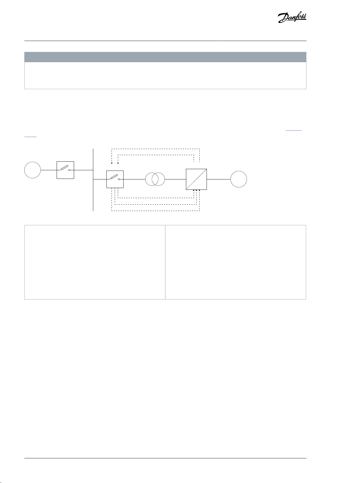
G
CB1
5
4
3
2
1
CB2
MVD
M
~
~
e30bi562.10
1
Trip coil: RO from VACON® 3000 (reaction time:
10 ms delay)
2
Undervoltage release (UVR): IGBT switch from arc
flash relay (reaction time: 2 ms delay)
3
Breaker open: RO from the breaker
4
Breaker closed: RO from the breaker
5
Breaker ready (optional): RO from the breaker
CB1
Circuit breaker 1
CB2
Circuit breaker 2
G
Grid or generator
M
Motor
MVD
VACON® 3000 medium-voltage drive
VACON® 3000 Enclosed Drive
Operating Guide
Safety
N O T I C E
PERSONAL PROTECTIVE EQUIPMENT AND APPROVED TOOLS
When doing electrical work on the AC drive, always use personal protective equipment (PPE) and tools which are approved for
work with medium-voltage devices.
2.5 Main Circuit Breaker
The main circuit breaker (MCB) is an important protection device for the drive. If there is a serious fault in the drive, the MCB immediately disconnects the main supply to the drive. To protect personnel and to prevent further damage to the equipment, the main
supply must be disconnected immediately with an open or trip command from the drive.
If the drive is supplied through a dedicated transformer, install the MCB on the primary side of the supply transformer (see Illustra-
tion 1).
Illustration 1: Overview of the Drive System
2.5.1 Safety and Protection Requirements
For safety and protection, the MCB must meet the minimum requirements of the specifications of Danfoss medium-voltage drives.
The minimum requirements for the MCB are stated in this manual and in the respective MCB specifications, which are available for
each medium-voltage drive from Danfoss. The system integrator must make sure that the minimum requirements are met.
The safety requirements for the drive are based on the following standards:
•
EN ISO 13849-1: Safety of machinery, Safety-related parts of control systems, General principles for design, section 6.2.6 Category 3
•
UL347A, Edition 1: Standard for Medium Voltage Power Conversion Equipment
2.5.2 Minimum Requirements for MCB and MCB Control
Requirements
To meet the stipulated safety requirements, Danfoss requires the following:
•
MCB is equipped with 2 independent opening coils.
•
MCB is equipped with an opening coil and an undervoltage coil for monitoring of the control voltage.
•
Route the MCB open and trip commands directly from the drive to the MCB.
-
Do not route the trip command through any PLC or DCS (distributed control system) which is not certified to meet SIL 3level requirements and to fulfill the given timing requirements.
-
Opening of the MCB by the drive must be possible at any time. Do not interrupt the open and trip commands, for example,
by a local-remote switch in the MCB.
AQ286660579921en-000101 / DPD0203314 | Danfoss A/S © 2021.09

VACON® 3000 Enclosed Drive
Operating Guide
•
Closing the MCB locally is not permitted. When the MCB is in the service position, the drive must have exclusive control of closing the MCB.
•
The maximum opening time of the MCB must never exceed the product or project specific maximum time defined in the MCB
specifications.
•
Typical maximum protection and safety trip time for the drive: 60 ms
Recommendations
To meet the stipulated safety requirements, Danfoss recommends the following:
•
Provide an upstream protection coordination scheme which uses the "breaker failure" (ANSI 50BF) signal to trip the upstream
breaker automatically, in case the MCB does not open.
•
After a failure has occurred, the upstream breaker must open within the maximum protection and safety trip time.
Safety
AQ286660579921en-000101 / DPD02033 | 15Danfoss A/S © 2021.09
e30bg963.10
VACON® 3000 Enclosed Drive
Operating Guide
Product Overview
3 Product Overview
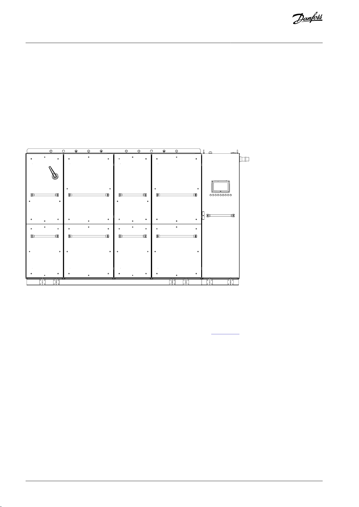
3.1 Intended Use
VACON® 3000 is a liquid-cooled AC drive for stepless speed or torque control of medium-voltage induction motors. VACON® 3000
Enclosed Drive is a complete medium-voltage drive installed in a cabinet.
VACON® 3000 Enclosed Drive is available for industrial applications with motor voltages of 3300 V and 4160 V, and in a power range
starting from 2 MW. Basic configurations have a power of 2 MW or 3 MW. These configurations can be paralleled for systems of 4
MW and above.
Two different drive configurations are available:
•
Regenerative, with an active front-end (AFE)
•
Non-regenerative, with a 12-pulse diode front-end (DFE)
Illustration 2: Example of the VACON® 3000 Enclosed Drive
3.2 Product Description
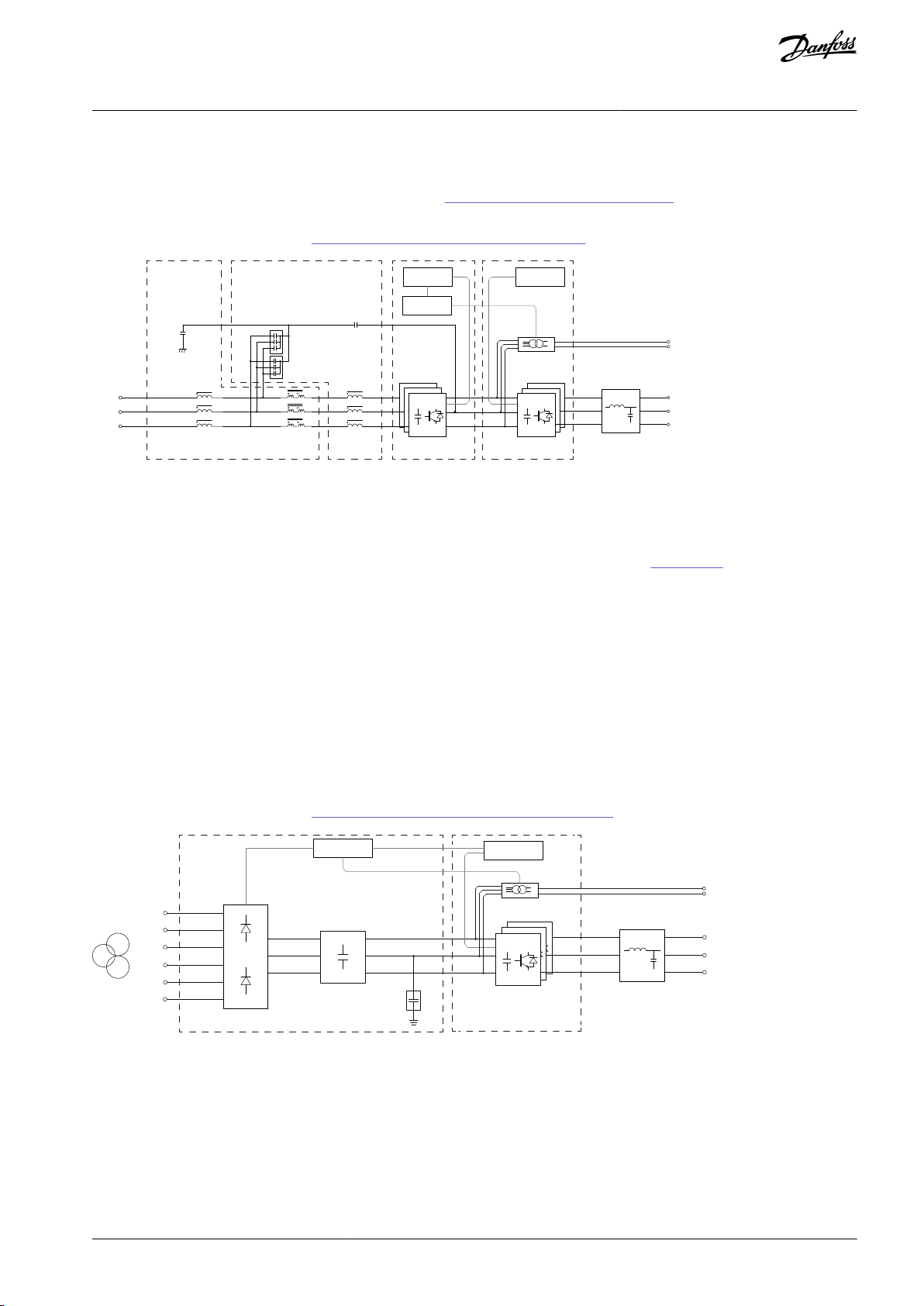
3.2.1 AFE Drive
An example diagram of the regenerative VACON® 3000 Enclosed Drive is shown in Illustration 3. The main components of the drive
are:
•
The active front-end (AFE) unit includes 3 or 6 liquid-cooled 1-phase power conversion units (PCU). 3 of the phase modules are
installed in parallel to make a 3-phase converter. The AFE converts the supplied AC voltage to DC voltage. It also enables the
supply of power to the supply network when the motor is braking.
•
The inverter unit (INU) includes 3 or 6 of the same liquid-cooled 1-phase modules, which are used in the AFE. The INU converts
the DC voltage to the AC voltage and frequency supplied to the motor.
•
The LC filter (FLC) limits harmonic current on the supply network.
•
The pre-charge unit (PRC) charges the DC-link capacitors.
•
The AFE and INU control units (CNU-AFE/CNU-INU) are connected to the power conversion units with optical fibers.
•
The auxiliary I/O board (AXU-IOB) provides galvanic separation between I/Os in the MV section and the control unit in the LV
section of the cabinet.
The basic VACON® 3000 AFE drive is intended for installations, where the system is supplied by a dedicated transformer and the
source impedance is small. These installations are usually on land. The drive includes an LC filter instead of an LCL filter, because the
supply side inductance is included in the dedicated transformer.
It is recommended to install a dedicated transformer for the drive. If the drive is not supplied by a dedicated transformer (that is,
there are other loads than the drive on the same supply):
AQ286660579921en-000101 / DPD0203316 | Danfoss A/S © 2021.09
CCM
CCM
LGI LCM LCV
+
-
o
+
-
o
CNU-AFE CNU-INU
3 x PCU
3 x PCU
PRC
CSH
INUAFEFLC+PICM
MV~
+PODU
+POSI
Motor
LV~
e30bg606.10
AXU-IOB
+
-
CCM
+
-
00
+
-
0
Motor
CDC
PCU
3 x PCU
CNU-INU
AXU-IOB
PRC
MV~
LV~
MV~
12P-DFE
INU
+PODU
+POSI
Y
Δ
Δ
e30bg607.10
VACON® 3000 Enclosed Drive
Operating Guide
•
Install the drive in a high resistance grounding system with a resistance grounded neutral point.
•
Install an input common-mode filter (option +PICM).
Product Overview
If the source impedance is high, select the +PHSI option. See 11.2.7 Source Impedance Specifications.
For operation in an IT network without a dedicated transformer, contact Danfoss.
For the full main circuit diagrams, see 11.3.1 VACON® 3000 AFE Main Circuit Diagrams.
Illustration 3: Example Main Circuit Diagram of a VACON® 3000 AFE Drive
3.2.2 12-Pulse Drive
An example diagram of the 12-pulse non-regenerative VACON® 3000 Enclosed Drive is shown in Illustration 4. The main components of the drive are:
•
The diode front-end unit (DFE) is a liquid-cooled 12-pulse power conversion unit (PCU), which changes the supplied AC voltage
to DC voltage. The 12-pulse configuration is used to limit harmonics on the supply network.
•
The inverter unit (INU) includes 3 or 6 liquid-cooled 1-phase power conversion units (PCU). 3 of the phase modules are installed
in parallel to make a 3-phase converter. The INU converts the DC voltage to the AC voltage and frequency supplied to the motor.
•
The pre-charge unit (PRC) charges the DC-link capacitors.
•
The INU control unit (CNU-INU) is connected to the inverter units with optical fibers.
•
The auxiliary I/O board (AXU-IOB) provides galvanic separation between I/Os in the MV section and the control unit in the LV
section of the cabinet.
The 12-pulse DFE must be supplied by a dedicated transformer with two secondary windings.
For the full main circuit diagrams, see 11.3.2 VACON® 3000 12-Pulse Main Circuit Diagrams.
Illustration 4: Example Main Circuit Diagram of a VACON® 3000 12-Pulse Drive
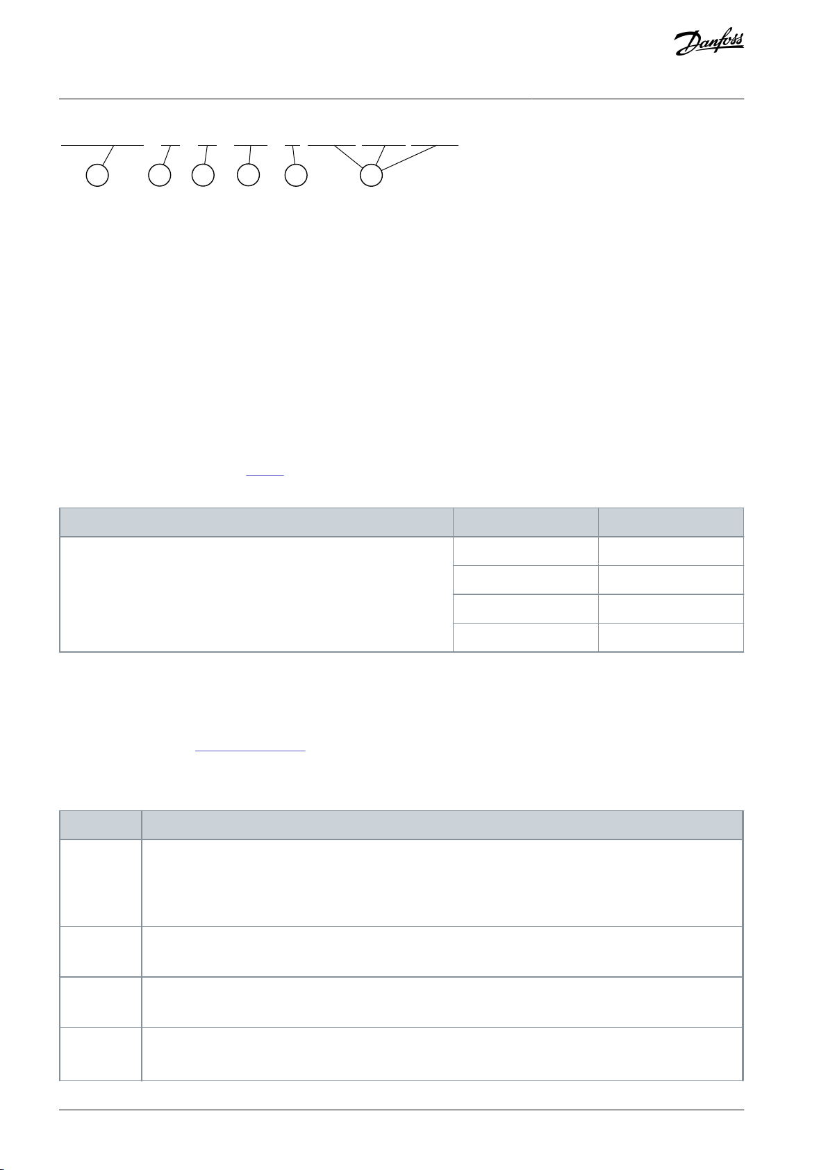
3.3 Type Code Description
The type code for VACON® 3000 has five basic parts (1–5) and option codes (6).
AQ286660579921en-000101 / DPD02033 | 17Danfoss A/S © 2021.09
1
3
4
5 6
2
V
ACON3000 - ED - 4Q - 0425 - 03 +XXXX +YYYY +ZZZZ
e30bg964.10
Input voltage [V]
3300
4160
Output current [A]
0425
0340
0640
0510
0820
0650
1230
0980
Option Code
Option Description
+PICM
(1)
Input common-mode filter
The option is only available for AFE drives.
Always include the input common-mode filter in VACON® 3000 AFE installations, which are not supplied by a
dedicated transformer.
+PODU
(1)
dU/dt output filter
+POSI
(1)
Sine-wave output filter
+POCM
(1)
Output common-mode filter
Contact Danfoss to check the common-mode capacitor option selection.
VACON® 3000 Enclosed Drive
Operating Guide
Illustration 5: VACON® 3000 Type Code Structure
Product Overview
1. Product series
VACON® 3000. This part of the code is always the same.
2. Product class
The VACON® 3000 product.
•
ED: Enclosed Drive
3. Drive type
There are two different drive types available. All kits include an inverter unit (INU) as default. The front-end type is specified in the
type code.
•
4Q: A regenerative drive with an active front end (AFE) and an LC input filter, supplied through a dedicated transformer. If the
drive is not supplied by a dedicated transformer, install a common-mode filter (available with option code +PICM).
•
12: A non-regenerative drive with a 12-pulse diode front end (DFE) rectifier and external DC capacitors. A dedicated transformer
with 2 secondary windings is necessary.
4. Nominal output current
See the available output currents in
Table 2.
Table 2: Available Output Current Ratings
5. Nominal input voltage
Nominal supply voltage: 03 = 3300 V or 04 = 4160 V.
6. Option codes
Optional components.
See the available codes in 3.4 Available Options.
3.4 Available Options
Table 3: Available Options for VACON® 3000 Enclosed Drive
AQ286660579921en-000101 / DPD0203318 | Danfoss A/S © 2021.09

Option Code
Option Description
+DBCU
(1)
Brake chopper unit for dynamic braking
The option does not include a brake resistor.
The option is for 12-pulse drives. If a brake chopper is required for an AFE drive, contact Danfoss.
+PHSI
High source impedance
Option for installation locations with high source impedances (~10–15% SI). For example, marine applications
usually have a high source impedance. The option affects the size of the input filters. The default installation location has small source impedance (SSI).
This option is only available for AFE drives.
Examine each application one by one. To see if this option is necessary, find out the source impedance and see
11.2.7 Source Impedance Specifications. If necessary, consult Danfoss.
+SC__
+SD__
+SE__
C, D, and E slot option boards
Default: No option boards in slots C, D, and E.
See the available option boards in Table 4.
+QSTO
Safe torque off functionality.
Only available for AFE drives.
+QFV1
+QFV2
Control and fan supply voltage
115 V (default for 4160 V)
230 V (default for 3300 V)
+PGDR
+PGDN
Grounding of the heat sink and connection of the grounding resistor in power modules
R: DC neutral-to-ground resistor connected (default)
N: DC neutral-to-ground resistor not connected
+PLIN
+PLDI
Liquid cooling options
IN: Industrial water and grounded heat sink
DI: Deionized water and floating heat sink
+PUFE
Short-circuit current rating: 40 kA, for 100 ms.
Available only for AFE drives.
+PGC0
Common-mode capacitor to ground removed
+PLCT
Coolant input from the top
+PHET
+PH00
Heat exchanger option
ET: Titanium liquid-to-liquid heat exchanger included
00: Liquid-to-liquid heat exchanger not included
+QP24
+QP40
+QP48
Precharge input voltage
240 V
400 V (default for 3300 V)
480 V (default for 4160 V)
+GAUL
cUL certificate
+GACE
EU declaration, CE approval
+GADN
Marine approval
DN: Det Norske Veritas
VACON® 3000 Enclosed Drive
Operating Guide
Product Overview
AQ286660579921en-000101 / DPD02033 | 19Danfoss A/S © 2021.09
Option Code
Option Description
+GALR
LR: Lloyd's Register
Slot C
Slot D
Slot E
Option Board
(1)
+SCB1
+SDB1
+SEB1
I/O board OPTB1: 6 x Digital input/digital output, programmable
+SCB2
+SDB2
+SEB2
I/O board OPTB2: 1 x relay output (NO/NC), 1 x relay output (NO), Thermistor
+SCB4
+SDB4
+SEB4
I/O board OPTB4: 1 x analog input, 2 x analog output (isolated)
+SCB5
+SDB5
+SEB5
I/O board OPTB5: 3 x relay output
+SCB9
+SDB9
+SEB9
I/O board OPTB9: 1 x relay output, 5 x digital input (42–240 V AC)
+SCBF
+SDBF
+SEBF
I/O board OPTBF: 1 x analog output, 1 x digital output, 1 x relay output
+SCBH
+SDBH
+SEBH
I/O board OPTBH: 3 x Temperature measurement (support for PT100, PT1000, NI1000, KTY84-130,
KTY84-150, KTY84-131 sensors)
+SDD3
+SED3
Adapter board OPTD3: RS232 adapter
+SDE3
+SEE3
Fieldbus board OPTE3: PROFIBUS DP-V1 (Screw connector)
+SDE5
+SEE5
Fieldbus board OPTE5: PROFIBUS DP-V1 (D9 connector)
+SDE6
+SEE6
Fieldbus board OPTE6: CANopen
+SDE7
+SEE7
Fieldbus board OPTE7: DeviceNet
+SDE9
+SEE9
Fieldbus board OPTE9: 2-port Ethernet
+SDEA
+SEEA
Fieldbus board OPTEA: Advanced 2-port Ethernet
+SDEC
+SEEC
Fieldbus board OPTEC: EtherCAT
VACON® 3000 Enclosed Drive
Operating Guide
1
The nominal current and voltage selected in the type code of the VACON® 3000 affect this option. The correct size and number of parts is supplied
automatically. If a different size or number of parts is needed, an order for separate parts is possible.
Table 4: Available Option Boards for Slots C, D, and E
Product Overview
1
For a 12-pulse drive, the option includes one board. For an AFE drive, the option includes two boards, one for the AFE control unit and one for the
INU control unit. If the drive also has the brake chopper option (+DBCU), the option includes one more board for the brake chopper control unit.
AQ286660579921en-000101 / DPD0203320 | Danfoss A/S © 2021.09
VACON® 3000 Enclosed Drive
Operating Guide
Receiving the Delivery
4 Receiving the Delivery
4.1 Checking the Delivery
1.
After removing the packaging, examine the drive for transport damages.
-
If the drive was damaged during the shipping, speak to the cargo insurance company or the carrier.
2.
To make sure that the delivery is correct, compare the type code for the order to the type code on the package label. The
type code specifies the drive type, nominal output current, nominal input voltage, and option codes. See 3.3 Type Code
Description.
-
If the delivery does not agree with the order, speak to the vendor immediately.
4.2 Storage
N O T I C E
LIQUID IN THE HEAT SINK
If the cooling liquid is not removed from the heat sink before storage or shipping, the liquid can freeze and damage the drive.
Always remove the cooling liquid from the heat sink before storage or shipping.
-
If the AC drive is kept in storage, keep it in controlled conditions.
•
Storage temperature: -40…+70°C (-40... +158°F). If the storage temperature is below 0°C (+32°F), make sure that there is no
cooling liquid in the heat sink.
•
Relative humidity: < 96%, no condensation
Keep the equipment sealed in its packaging until installation.
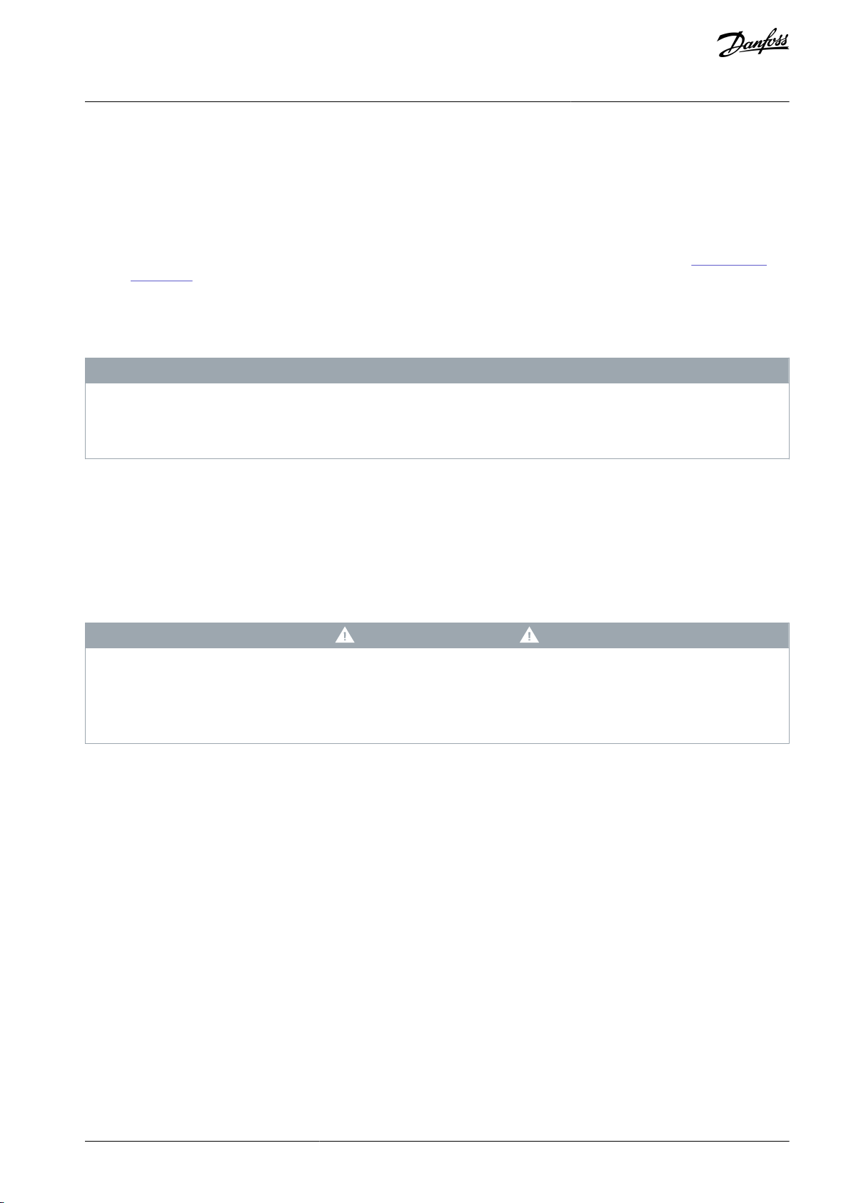
4.3 Lifting and Moving the Enclosed Drive
W A R N I N G
LIFTING HEAVY EQUIPMENT
Follow local safety regulations for lifting heavy weights. Failure to follow recommendations and local safety regulations can result
in death or serious injury.
Ensure that the lifting equipment is in proper working condition.
-
The cabinets must be moved vertically. Always refer to the shipping marks on the package for more information. Do not remove the
package material before installing the AC drive.
To lift the cabinets, use a lifting device that can lift the weight of the cabinets. There are lifting holes on the top of the cabinets. Use
these holes to lift the cabinets and to move them to the installation location. The minimum angle between the cabinets and the
chain is 60°.
To divide the weight of the cabinets equally, and to prevent damage to the equipment, always use 4 lifting holes. Align the lifting
locations with the horizontal center of gravity.
AQ286660579921en-000101 / DPD02033 | 21Danfoss A/S © 2021.09
e30bg965.10
>60°
>60°
e30bg966.10
VACON® 3000 Enclosed Drive
Operating Guide
Illustration 6: Lifting the Cabinets
Receiving the Delivery
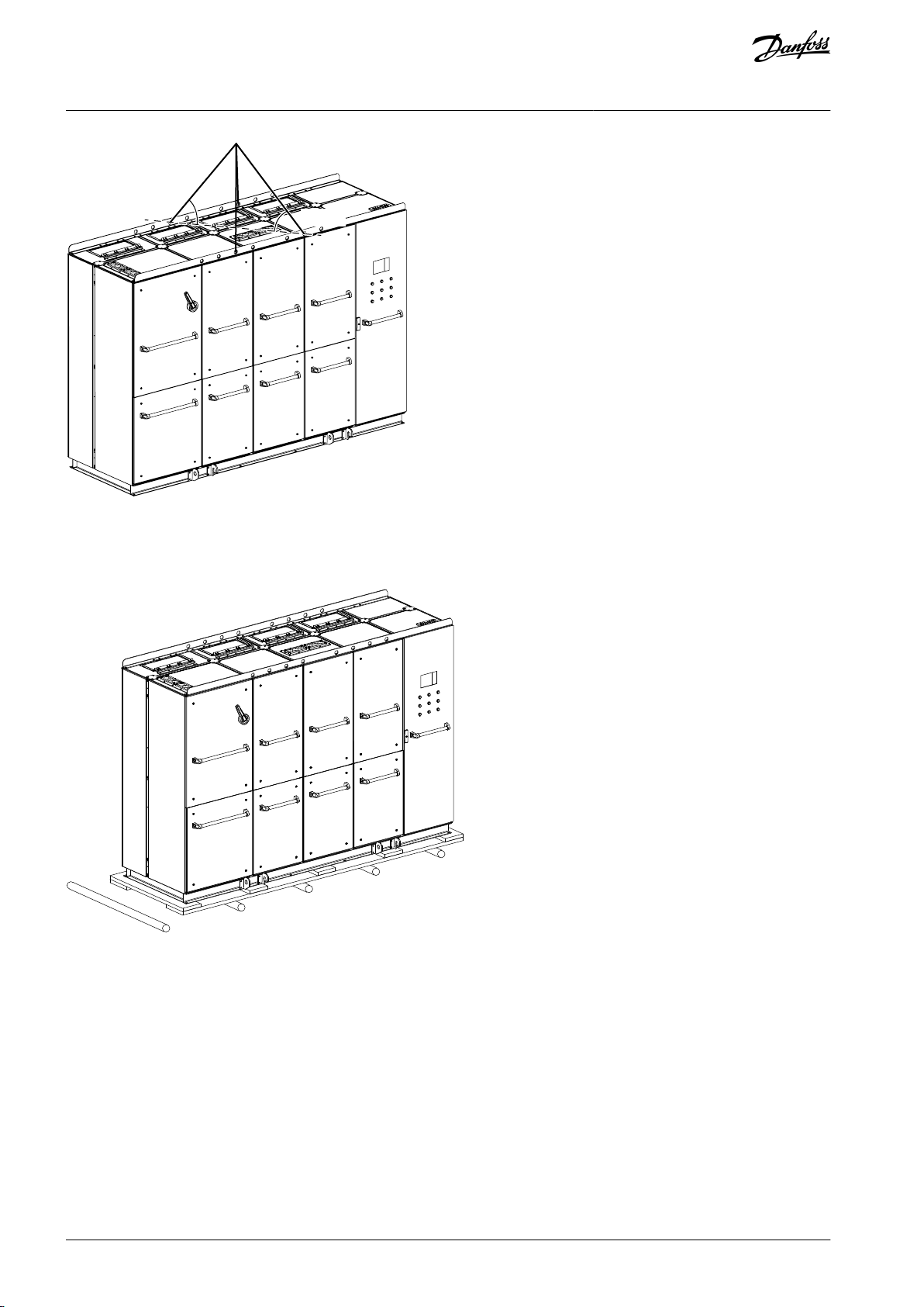
You can use rollers, for example, to move the cabinets.
Move the cabinets carefully. Switchgear parts can easily fall because their center of gravity is high up at the back of the cabinets.
Illustration 7: Moving the Cabinets
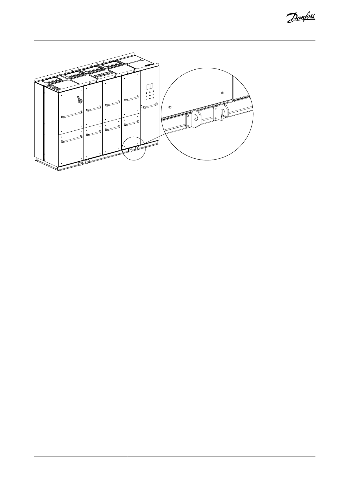
When the cabinet is in the installation location, it can be necessary to make small adjustments to the position of the cabinet. Use a
crowbar to move the cabinet from the special hooks on the cabinet base.
Remove the moving hooks from the base of the cabinet before installation.
AQ286660579921en-000101 / DPD0203322 | Danfoss A/S © 2021.09
e30bg967.10
VACON® 3000 Enclosed Drive
Operating Guide
Illustration 8: Hooks on the Cabinet Base for Adjusting the Position of the Cabinet
Receiving the Delivery
AQ286660579921en-000101 / DPD02033 | 23Danfoss A/S © 2021.09

VACON® 3000 Enclosed Drive
Operating Guide
Mechanical Installation
5 Mechanical Installation
5.1 Operating Environment
N O T I C E
CONDENSATION
Moisture can condense on the electronic components and cause short circuits.
Avoid installation in areas subject to frost.
-
Install space heaters to warm the air inside the cabinets.
Before powering the drive, run the cooling pumps to warm up the components, until the drive is warmer than the ambient
air.
N O T I C E
EXTREME AMBIENT CONDITIONS
Hot or cold temperatures compromise unit performance and longevity.
In environments with airborne liquids, particles, or corrosive gases, ensure that the IP/Type rating of the equipment matches the
installation environment. For specifications regarding ambient conditions, see 11.2.5 Ambient Conditions.
5.2 Cabinet Installation
Installation guidelines:
•
Locate the drive as near to the motor as possible.
•
Ensure unit stability by mounting the enclosure on a solid surface.
•
Make sure that the level of the floor is in permitted limits. The maximum deviation from the basic level can be no more than 5
mm (0.197 in) along a 3 m (9.84 ft) distance. The maximum permitted height difference between the cabinet front and rear
edges is 2 mm (0.079 in).
•
Ensure that the strength of the mounting location supports the unit weight.
•
It is not recommended to install the cabinet directly against a wall.
•
Attach the cabinet to the floor. There are holes in the base of the cabinet which can be used for the installation.
•
Ensure that there is enough space around the unit for proper cooling.
•
Ensure that there is enough room to open the cabinet doors and for working on the equipment.
•
Remove the moving hooks from the base of the cabinet before installation.
AQ286660579921en-000101 / DPD0203324 | Danfoss A/S © 2021.09
A C
B
e30bg968.10
A–C
See the dimensions in Table 5.
Type code
Dimension A
Dimension B
Dimension C
VACON3000ED-4Q-0425-03
2400 mm (7 ft 10.5 in)
2130 mm (6 ft 11.9 in)
1000 mm (3 ft 3.4 in)
VACON3000ED-4Q-0640-03
2600 mm (8 ft 6.4 in)
2130 mm (6 ft 11.9 in)
1000 mm (3 ft 3.4 in)
VACON3000ED-4Q-0820-03
3800 mm (12 ft 5.6 in)
2130 mm (6 ft 11.9 in)
1000 mm (3 ft 3.4 in)
VACON3000ED-4Q-1230-03
4400 mm (14 ft 5.2 in)
2130 mm (6 ft 11.9 in)
1000 mm (3 ft 3.4 in)
VACON3000ED-4Q-0340-04
2400 mm (7 ft 10.5 in)
2130 mm (6 ft 11.9 in)
1000 mm (3 ft 3.4 in)
VACON3000ED-4Q-0510-04
2600 mm (8 ft 6.4 in)
2130 mm (6 ft 11.9 in)
1000 mm (3 ft 3.4 in)
VACON3000ED-4Q-0650-04
3800 mm (12 ft 5.6 in)
2130 mm (6 ft 11.9 in)
1000 mm (3 ft 3.4 in)
VACON3000ED-4Q-0980-04
4400 mm (14 ft 5.2 in)
2130 mm (6 ft 11.9 in)
1000 mm (3 ft 3.4 in)
VACON3000ED-12-0425-03
2400 mm (7 ft 10.5 in)
2130 mm (6 ft 11.9 in)
1000 mm (3 ft 3.4 in)
VACON3000ED-12-0640-03
2600 mm (8 ft 6.4 in)
2130 mm (6 ft 11.9 in)
1000 mm (3 ft 3.4 in)
VACON3000ED-12-0820-03
3400 mm (11 ft 1.9 in)
2130 mm (6 ft 11.9 in)
1000 mm (3 ft 3.4 in)
VACON3000ED-12-1230-03
3800 mm (12 ft 5.6 in)
2130 mm (6 ft 11.9 in)
1000 mm (3 ft 3.4 in)
VACON® 3000 Enclosed Drive
Operating Guide
Mechanical Installation
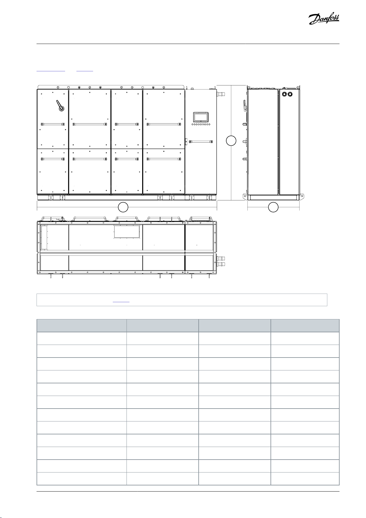
5.3 Dimensions of the Enclosed Drive
Illustration 9 and Table 5 show the dimensions of the basic VACON® 3000 Enclosed Drive. Some options can affect the total width or
height of the cabinet. Always refer to the delivery-specific information for the accurate dimensions.
Illustration 9: Dimensions of the VACON® 3000 Enclosed Drive
Table 5: Dimensions of the VACON® 3000 Enclosed Drive
AQ286660579921en-000101 / DPD02033 | 25Danfoss A/S © 2021.09
Type code
Dimension A
Dimension B
Dimension C
VACON3000ED-12-0340-04
2400 mm (7 ft 10.5 in)
2130 mm (6 ft 11.9 in)
1000 mm (3 ft 3.4 in)
VACON3000ED-12-0510-04
2600 mm (8 ft 6.4 in)
2130 mm (6 ft 11.9 in)
1000 mm (3 ft 3.4 in)
VACON3000ED-12-0650-04
3400 mm (11 ft 1.9 in)
2130 mm (6 ft 11.9 in)
1000 mm (3 ft 3.4 in)
VACON3000ED-12-0980-04
3800 mm (12 ft 5.6 in)
2130 mm (6 ft 11.9 in)
1000 mm (3 ft 3.4 in)
VACON® 3000 Enclosed Drive
Operating Guide
5.4 Liquid Cooling Requirements
5.4.1 Safety in Liquid-cooling
W A R N I N G
POISONOUS COOLANTS
Glycols and inhibitors are poisonous. If touched or consumed, they can cause injury.
Prevent the coolant from getting into the eyes. Do not drink the coolant.
-
C A U T I O N
HOT COOLANT
Hot coolant can cause burns.
Avoid contact with the hot coolant.
-
Mechanical Installation
C A U T I O N
PRESSURIZED COOLING SYSTEM
Sudden release of pressure from the cooling system can cause injury.
Be careful when operating the cooling system.
-
N O T I C E
INSUFFICIENT COOLING CAPACITY
Insufficient cooling can cause the product to become too hot and thus become damaged.
To make sure that the cooling capacity of the cooling system stays sufficient, make sure that the cooling system is vented
-
and that the coolant circulates properly.
5.4.2 General Information on Liquid Cooling
VACON® 3000 drives are liquid-cooled. The liquid circulation of the drive is connected to a heat-exchanger that cools down the
liquid circulating in the cooling elements of the drive. The power modules have aluminum heat sinks, which give good and safe
temperature control. Because the cooling elements are made of aluminum, the cooling liquids allowed to be used are inhibited
pure water, inhibited demineralized water, or an inhibited mixture of water and glycol.
The inductors of the input and output filters use air-to-liquid heat exchanger units for forced air cooling. The heat exchangers decrease the heat losses to the air and thus decreases the number of fans necessary for cooling the cabinet.
There are two types of cooling systems: open systems and closed systems.
An open system has no pressure but the hydrostatic and pumping pressure. It allows free contact between the cooling liquid and
air. Air is continuously dissolved into the cooling liquid.
In a closed system, the piping is air-tight and there is a preset pressure inside the pipes. The pipes must be made of metal, or a
specific plastic or rubber that includes an oxygen barrier that limits the diffusion of oxygen. Minimizing of oxygen content in the
cooling liquid decreases the risk of corrosion of the metal parts. Closed systems usually have an expansion vessel that allows for a
safe change of volume of the cooling liquid due to temperature changes.
Always use a closed system with Danfoss liquid-cooled drives.
AQ286660579921en-000101 / DPD0203326 | Danfoss A/S © 2021.09
Property
Required value
pH
6...8
Chlorides
≤ 25 ppm
Sulphate ions
≤ 25 ppm
Maximum particle size
≤ 50 µm
Total dissolved solids
≤ 200 ppm
Total hardness (CaCO3)
3…4.6 dH° (53…80 ppm)
Hydrogen carbonate
≤ 50 ppm
Electrical conductivity
≤ 500 µS/cm
VACON® 3000 Enclosed Drive
Operating Guide
5.4.3 Cooling Liquid
5.4.3.1 Quality Requirements for the Purified Water
N O T I C E
DAMAGE TO SYSTEM FROM THE USE OF HYDROCARBONS
Hydrocarbons damage the rubber seals of the cooling system.
Do not use hydrocarbons (for example mineral oil) as coolant. Do not mix hydrocarbons to coolant.
-
Table 6: Requirements for the Purified Water
Mechanical Installation
5.4.3.2 Purified Water as Coolant
Purified water can be used as coolant if there is no risk of freezing. Freezing water permanently damages the cooling system. Purified water is demineralized, deionized, or distilled water.
Always use an inhibitor Cortec VpCI-649 with 1.0% of volume with purified water.
C A U T I O N
CORROSION HAZARD WITH DRINKING WATER
Some components are made of aluminum, which has limited corrosion resistance against high chloride concentrations. Drinking
water can have a chloride concentration of 250 ppm, which increases the aluminum corrosion rate. High chloride concentration
exposes aluminum especially to pitting corrosion which can damage the system relatively quickly.
Use purified (demineralized, deionized, or distilled) water with corrosion inhibitors.
-
5.4.3.3 Antifreeze Mix as Coolant
The following antifreeze products are a good general solution for liquid cooling since they provide freeze protection and corrosion
protection.
The allowed antifreeze coolants are the following ethylene glycols and propylene glycols.
Ethylene glycols
•
DOWCAL 100
•
Clariant Antifrogen N
Propylene glycols
•
DOWCAL 200
•
Clariant Antifrogen L
These glycols already include corrosion inhibitors. Do not add any other inhibitor. Do not mix different glycol qualities because
there can be harmful chemical interactions.
AQ286660579921en-000101 / DPD02033 | 27Danfoss A/S © 2021.09

VACON® 3000 Enclosed Drive
Operating Guide
The glycol concentration of the coolant must be 25–55% by volume, according to the specified ambient temperature. Higher concentration reduces cooling capacity. Lower concentration results in biological growth and inadequate amount of corrosion inhibitors. Antifreeze must be mixed with purified water according to 5.4.3.1 Quality Requirements for the Purified Water.
Mechanical Installation
5.4.3.4 Temperature of the Cooling Liquid
To gain full performance of the product, the temperature of the cooling liquid entering the drive components must be a maximum
of 43°C (109°F) and above the dew point. While circulating inside the cooling element, the liquid transfers the heat produced by the
power semiconductors and other components. The temperature rise of the cooling liquid during the circulation is typically less than
4°C (7.2°F). Typically, more than 95% of the power losses are dissipated in the cooling liquid. It is recommended to equip the cooling
circulation with temperature supervision.
The secondary circuit maximum temperature must always be lower than the primary circuit temperature. The temperature difference must be at least 5°C (9°F) with equal flow. The temperature difference is necessary for the correct operation of the heat exchanger.
There are 3 external causes that affect the nominal temperature of the primary circuit:
•
The maximum ambient temperature at the drive installation location.
•
The maximum relative humidity at the drive installation location.
•
The maximum secondary circuit liquid temperature.
All these causes must be examined when calculating the primary circuit temperature. The primary circuit temperature can be different for each installation.
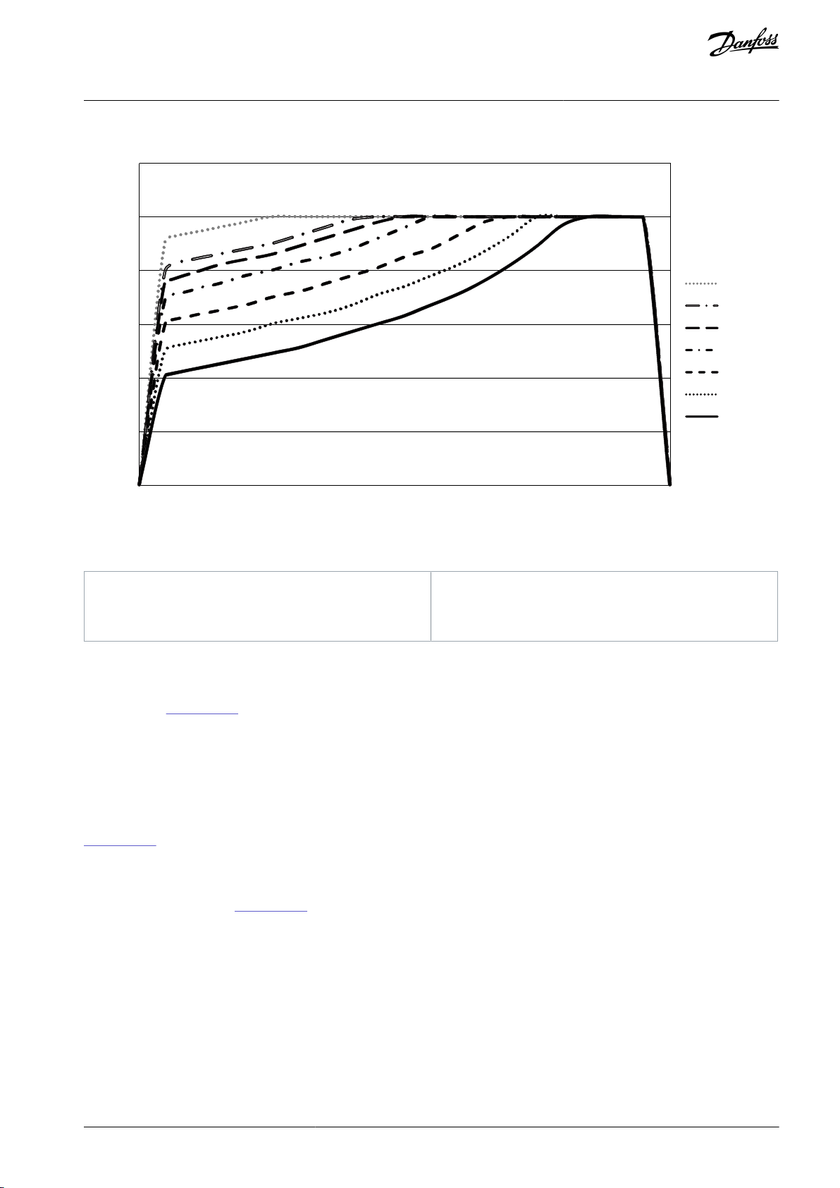
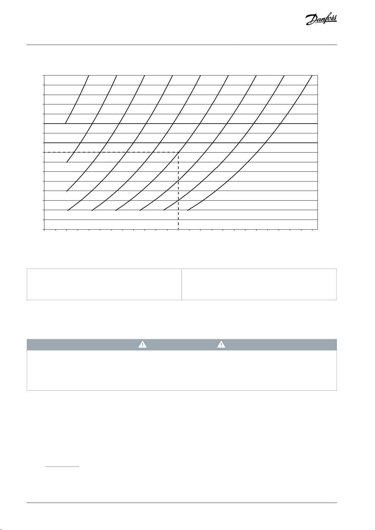
5.4.3.5 Condensation
Condensation must be avoided. Always keep the temperature of the cooling liquid a minimum 2°C (3.6°F) above the dew point. Use
the graph in Illustration 10 to see if the conditions (combination of room temperature, humidity, and cooling liquid temperature)
are safe for the drive to operate.
The conditions are safe when the point is below the related (cooling liquid temperature) curve. If they are not, decrease the ambient
temperature or the relative humidity. Also the cooling liquid temperature can be increased. Note, that if the cooling liquid temperature is increased above the figures in loadability charts, it decreases the nominal output current of the drive. The curves in Illustra-
tion 10 are valid at sea level altitude (1013 mbar/14.69 psi).
If the temperature of the liquid in the secondary circuit is lower than the ambient temperature and the relative humidity is high,
condensation can occur on the secondary circuit pipes and the plate heat exchanger in the HX unit. The condensation is not dangerous, but it is not recommended. If there is condensation in the HX unit, it can cause the leak sensor in the cabinet to give a leak
alarm. If a leak alarm occurs again and again, install insulation in the secondary circuit pipes and the plate heat exchanger. The
insulation stops the condensation and thus prevents the incorrect leak alarms.
AQ286660579921en-000101 / DPD0203328 | Danfoss A/S © 2021.09
0 (32)
10 (50)
20 (68)
30 (86)
40 (104)
50 (122)
60 (140)
e30bg701.10
0
10
20
30
40
50
60
70
80
90
100
T
amb
, °C (°F)
Tc, °C (°F)
RH (%)
45 (113)
40 (104)
38 (100)
35 (95)
30 (86)
25 (77)
20 (68)
RH
Relative humidity
T
amb
Ambient temperature
TcCooling liquid temperature
VACON® 3000 Enclosed Drive
Operating Guide
Mechanical Installation
Illustration 10: Safe Operating Conditions in Relation to Condensation
Example
Safe Operating Conditions
If the ambient temperature is +30°C (+86°F), the relative humidity is 40% and the cooling liquid temperature is +20°C (+68°F, the
lowest curve in Illustration 10), then the drive operation conditions are safe.
If the ambient temperature increases to +35°C (+95°F) and the relative humidity to 60%, then the operation conditions of the drive
are not safe. To get safe operation conditions, the ambient temperature must be decreased to +28°C (+82°F) or below. If it is not
possible to lower the ambient temperature, then the cooling liquid temperature can be increased to +25°C (+77°F) or above.
Example
Dew Point and Primary Circuit Temperature
If the ambient temperature and the maximum relative humidity at the drive installation location is known, the dew point chart (see
Illustration 11) can be used to find the correct temperature for the primary circuit.
•
Ambient temperature = 35°C (95°F)
•
Maximum relative humidity = 60%
According to the diagram in Illustration 11, the dew point for the given values is 26°C (78.8°F). Always keep the temperature of the
cooling liquid a minimum 2°C (3.6°F) above the dew point. Thus the primary circuit minimum temperature is set to 28°C (82.4°F).
The secondary circuit maximum temperature must always be 5°C (9°F) lower than the primary circuit temperature. Thus, in this example, the secondary circuit temperature must be below 23°C (73.4°F) during operation.
Notice, that these conditions are valid for the starting of the drive. After the start, the temperature inside the cabinet starts to increase and the humidity decreases.
AQ286660579921en-000101 / DPD02033 | 29Danfoss A/S © 2021.09
Tamb (°C/°F)
20
2364396438461050125414571661186420682272247526792882308632903493369738
100401044210844111461154811850122°C°F
°C
°F
25
30
35
40
45
50
55
60
65
70
75
80
85
90
95
100
10
50
15
59
20
68
25
77
30
86
35
95
40
104
45
113
50
122
Tc (°C/°F)
RH (%)
e30bg702.10
RH
Relative humidity
T
amb
Ambient temperature
TcPrimary circuit temperature
VACON® 3000 Enclosed Drive
Operating Guide
Mechanical Installation
Illustration 11: Dew Point Diagram for Ambient Temperatures between +10°C...+50°C (+50°F...+122°F) at 1013 mbar (14.69 psi)
5.4.4 Cooling System
5.4.4.1 Materials
COPPER OR COPPER ALLOY PARTS DAMAGE THE SYSTEM
Using copper or copper alloy pipes or parts in contact with the cooling liquid damages the system.
Do not use pipes made of copper or alloys that include copper. If metallic pipes are used in the cooling system, use alumi-
-
num or stainless steel pipes.
Allowed materials in the cooling system
These materials are allowed in the cooling system if they are compatible with the cooling liquid:
•
Aluminum (EN-AW6060, EN-AW6063, or EN-AW6082)
•
Stainless steel (AISI 304/316)
•
Plastic*
•
Elastomers (EPDM, NBR, FDM)*
* If plastic or elastomers are used, check material compatibility within the temperature range of the cooling liquid. See the specifications in 11.2.6 Cooling.
Do not use PVC, copper, brass, or other materials not compatible with the heat sink material or cooling liquid.
Recommended material for pipes
C A U T I O N
AQ286660579921en-000101 / DPD0203330 | Danfoss A/S © 2021.09

= =
≈
=
≈≈
AFE
TT
TT
PT
PI
LI
LS
LS
T
E
PI
M
M
M
P
P
PT
Bleeding
Filling
Temperature control
Drain
Liquid to air
heat exchangers
INU
==
≈
=
≈ ≈
e30bg969.10
E
Heat exchanger
LI
Level indication
LS
Level switch
M
Motor
P
Pump
PI
Pressure indication
PT
Pressure transmitter
T
TankTTTemperature transmitter
VACON® 3000 Enclosed Drive
Operating Guide
•
PA11
•
PA12
•
PEX with oxygen barrier
•
PEX-AL-PEX
Mechanical Installation
The electrical resistance of the plastic and rubber pipes must be >109 Ω.
5.4.4.2 Cooling System Overview
The cooling system has a bypass valve in the primary line and valves at each power module inlet. They make it possible to open and
clean the cooling system. Open the bypass valve and close the valves to the AC drive when cleaning the system. While commissioning the system, close the bypass valve and open the valves to the AC drive.
The cooling system has temperature, pressure, and leak supervision. They can be connected to the External fault digital input function. If the cooling liquid flow or pressure is too low, the temperature too high or of there is a leak, the supervision stops the drive.
Illustration 12: The Cooling System of the VACON® 3000 Enclosed Drive
5.4.4.3 Cooling Connections to the Enclosed Drive
Connect the cooling pipes to the heat exchanger at the top on the right side of the cabinet. See the locations of the input and
output pipe connections in Illustration 13.
AQ286660579921en-000101 / DPD02033 | 31Danfoss A/S © 2021.09

I
O
e30bg970.10
I
Cooling liquid input
O
Cooling liquid output
VACON® 3000 Enclosed Drive
Operating Guide
Mechanical Installation
Illustration 13: Locations of the Cooling Connections
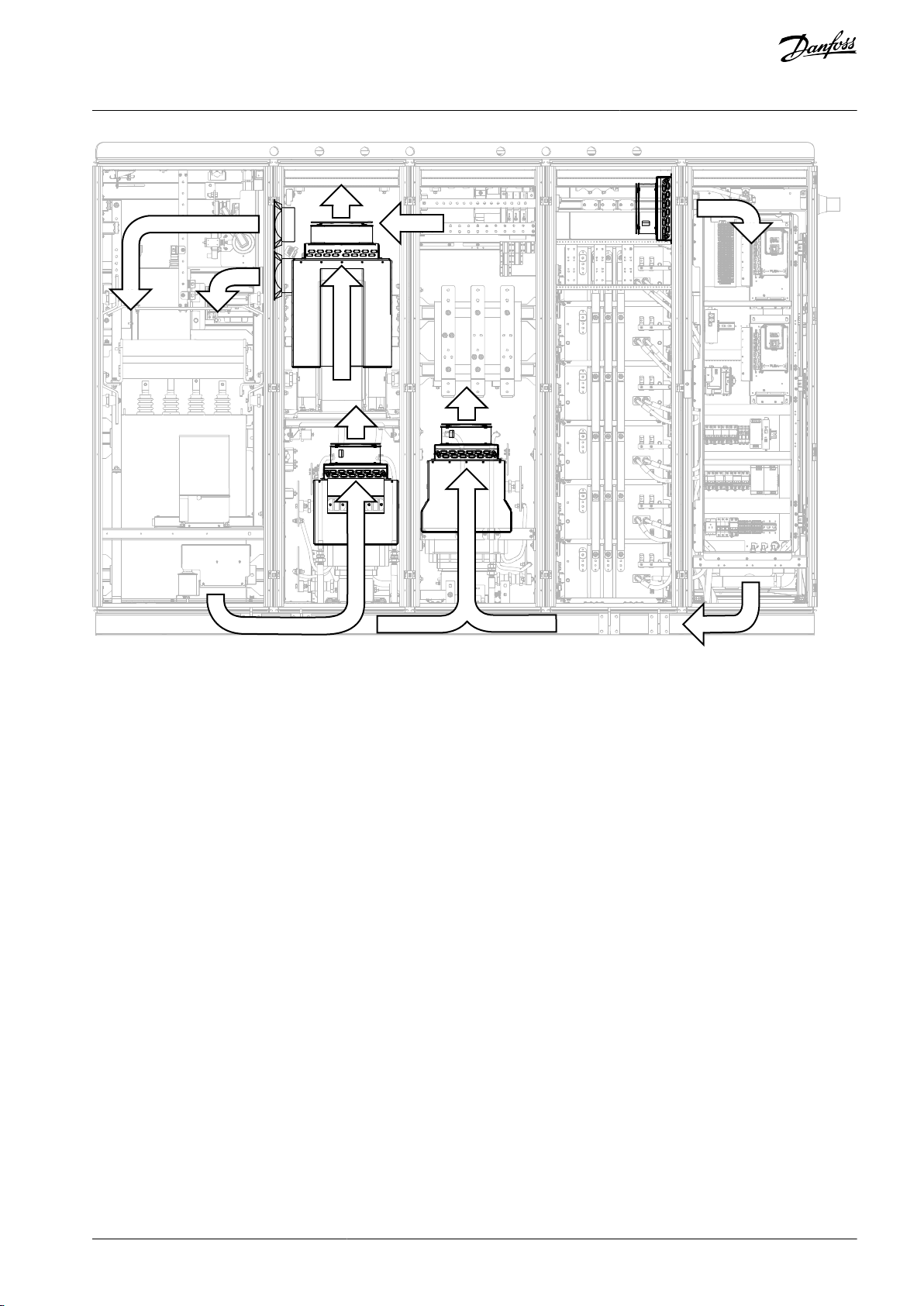
5.5 Cooling and Free Space Around the Enclosed Drive
The VACON® 3000 Enclosed Drive is a liquid-cooled AC drive, but in a liquid-cooled drive system, there are always some heat losses
to the air. The heat losses come from
•
busbars,
•
filters,
•
inductors,
•
other auxiliary components.
The AC drive uses liquid-to-air heat exchangers to cool the hot air from the inductors and other components. Fans in the cabinet
walls move the air between the cabinet sections. The structure of the cabinet is such, that the air can move freely through the cabinet.
There must be a minimum of 20 cm (7.87 in) of space above the cabinet without structures that can stop the airflow. Make sure that
the hot air goes out of the cabinet and does not come back into the cabinet. Some free space in front of the drive is also necessary
for maintenance.
The power loss of the AC drive can change significantly, when the load, the output frequency or the switching frequency changes. It
is useful to know the power loss, when planning the cooling equipment in an electrical room.
AQ286660579921en-000101 / DPD0203332 | Danfoss A/S © 2021.09
VACON® 3000 Enclosed Drive
Operating Guide
Mechanical Installation
e30bg713.11
Illustration 14: The Liquid-to-Air Heat Exchangers and Fans Used to Cool the Components in the Cabinets
AQ286660579921en-000101 / DPD02033 | 33Danfoss A/S © 2021.09
AFE
CSH
INU
CCM CCM
+PODU
+POSI
GSW
PTR
+
-
o
+
-
o
400/
480V
e30bg978.10
230/
120V
CNU-AFE
Aux I/O
CNU-INU
AIT
APS
PCU
PCU
LCVLGIMCB
LCM
Arc
flash
detector
L1
L2
L3
U
V
W
SPD
Cab
heater
Cab
heater
Cabinet
over temp
indicator
Cabinet
over temp
indicator
24 V - 20 A
24 V - 20 A
Panel
lighting
Panel
service
socket
L N PE
LSI
LCV
LCM
LGI
PRC
GSW
LD
MCB
COT
COT
DSI
Door safety
interlocks
HXLA
4160/
3300V
Motor
LOW-VOLTAGE SECTIONMEDIUM-VOLTAGE SECTION
Liq to air
HX
Power module
cabinet
Thermostat
Thermostat
Humidity
Magnetics
cabinet
Magnetics
cabinet
Magnetics
cabinet
PRC
Humidity
TB
HX Run O
I HX OK
Leak
detector
PS-BRK
L
N
HX
MTR
ESW
HMI
O - MX Start
I - KMX Status
I - VCB Status
O - VCB Close
O - MX Permissive
I - Power On
I - Power Off
I - GND SW Unlock
I - Arc Guard Online
I - Arc Guard Trip
I - HX OK
I - User Interlock
APS
24 V-10 A
24 V-10 A
Liq to airHXLiq to air
HX
A
B
C
C
E
D
Door safety
interlocks
Relay
Logic
L N
A
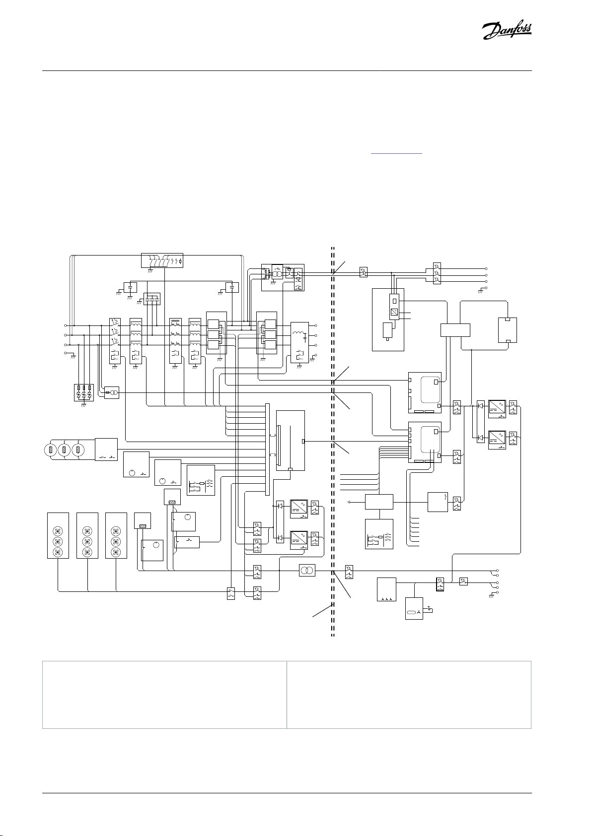
Galvanic isolation between the MV and LV sections
B
LV supply for the isolation transformer (AIT)
C
Optical fiber connections
D
Supply voltage feedback from the potential transformer (PTR) to the AFE control unit
E
LV supply for the pre-charge unit (PRC)
VACON® 3000 Enclosed Drive
Operating Guide
Electrical Installation
6 Electrical Installation
6.1 Galvanic Isolation Between the MV and LV Sections
There is galvanic isolation between the low-voltage (LV) and medium-voltage (MV) sections of the cabinet. The insulation between
the sections gives the devices in the LV section protection from the MV section voltages. Illustration 15 shows which components
are installed in the MV and LV sections.
All connections between the LV and MV sections are done with optical fiber cables. The only LV connections between the MV and
LV sections are:
•
The LV supply for the pre-charge unit (PRC)
•
The LV supply for the isolation transformer (AIT)
•
The supply voltage feedback from the potential transformer (PTR) to the AFE control unit
Illustration 15: Connections between the MV and LV Sections of the Cabinet
AQ286660579921en-000101 / DPD0203334 | Danfoss A/S © 2021.09
e30bg973.10
VACON® 3000 Enclosed Drive
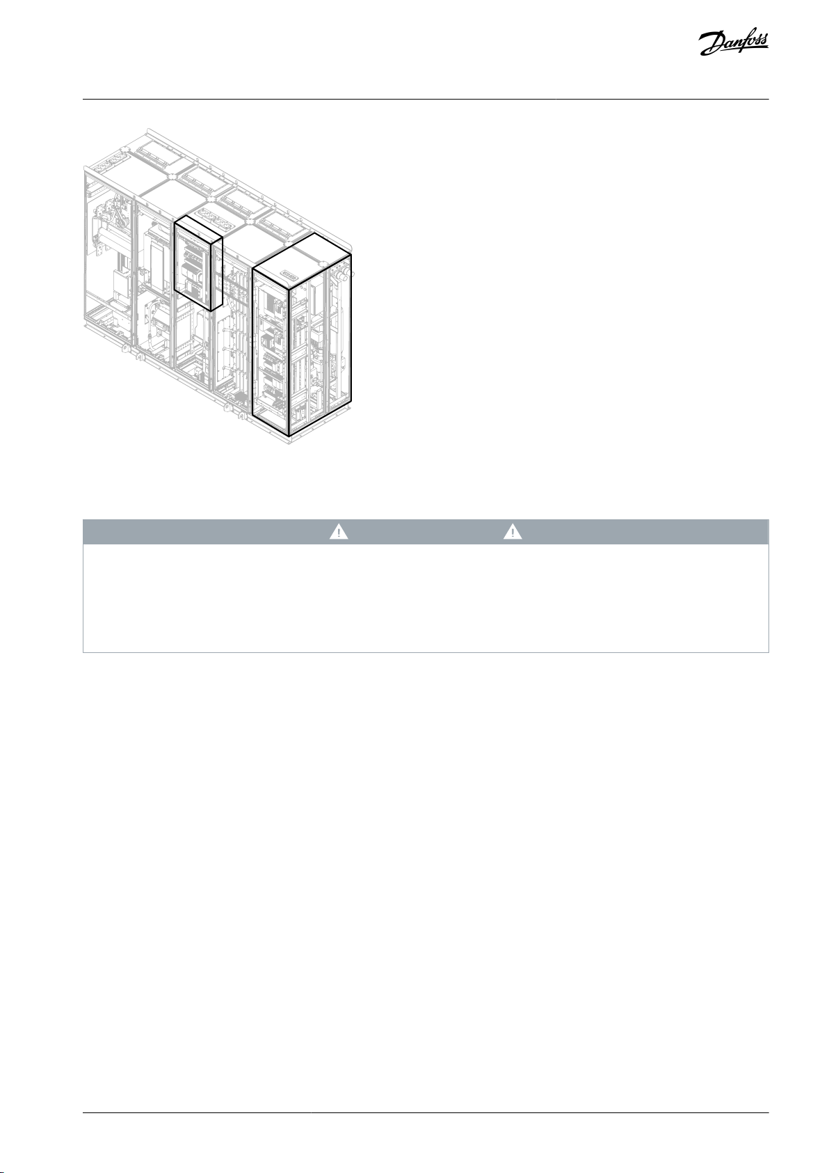
Operating Guide
Illustration 16: Locations of the Low-Voltage Sections in the VACON® 3000 Enclosed Drive
Electrical Installation
6.2 Mains and Motor Cable Selection
C A U T I O N
UNEQUAL LOAD
If the cable installation is not symmetrical, unequal load can occur in AC drives with parallel inputs or outputs. The unequal load
can decrease loadability or damage the drive.
In drives with parallel inputs or outputs, make sure that the cable size, cable length, cable type, and routing is the same for all
-
parallel cables.
Use cables with a nominal voltage U0/U of 3.6/6 kV and maximum voltage 7.2 kV. The size and type of the cable depends on the
application of the drive. The cable size is also affected by:
•
The current at continuous load,
•
the permitted short-circuit current,
•
the installation conditions.
To decrease EMI, use shielded 3-phase cables for the motor connection. If single-core cables are used in the input or output, they
must be shielded.
When selecting the cable, refer to the input voltage and the load current of the drive. Obey all applicable standards and local safety
regulations.
Example
Mains Cables for the VACON® 3000 4160 V 510 A AFE Drive
The recommendation for the VACON® 3000 4160 V 510 A AFE drive, is to use two 240 mm2 (500 kcmil) M2N type cables (available
from Liban Cables/Nexans) for each phase. The cables are 3.6/6 kV copper cables with one core, XLPE insulation, a PVC cover, shielded, and unarmored.
6.3 Mains and Motor Cable Inlet and Termination
There are cable entries at the top and bottom of the cabinet sections for the mains and motor cables. If an output filter option is
installed, cabling from the bottom is not possible.
AQ286660579921en-000101 / DPD02033 | 35Danfoss A/S © 2021.09

B
A
L1
L2
L3
W V U
e30bg971.10
A
The mains terminals (L1, L2, L3)
B
The motor terminals (U, V, W)
VACON® 3000 Enclosed Drive
Operating Guide
Illustration 17: The Mains and Motor Terminal Locations
Electrical Installation
Connect the mains cables to terminals L1, L2, and L3 in the mains input section. Connect the motor cables to the inverter section
terminals U, V, and W. Make openings for the cables in the grommets on the bottom or top of the cabinet and push through the
cables. Use cable clamps to attach the cables. Always connect the PE conductors of the mains and motor cables to the PE busbar.
In units with parallel motor outputs, do not connect the motor cables together in the AC drive end. Always connect the parallel
motor cables together in the motor end only. The minimum motor cable length is 5 m (16.4 ft).
Use medium-voltage cable lugs to connect the cables to the busbar terminals. Use heat shrink or cold shrink cable termination kits
on the cables, for example, the kits HIT1.1204L or CIT1.1204L available from Ensto.
The output cables to the motor must be 360° EMC grounded, for example, by installing EMC grounding clamps at the cable inlet. To
make a 360° connection with the grounding clamps and the cable shield, strip the cables. The EMC grounding clamps must be the
correct size to give a 360° contact with the cable shield.
AQ286660579921en-000101 / DPD0203336 | Danfoss A/S © 2021.09

E
D
C
B
A
F
e30bg732.10
A
Cable grommet
B
Cable clamp
C
360° EMC grounding
D
PE busbar
E
Cable termination
F
Cable lug
B
C
D
A
e30bh726.10
VACON® 3000 Enclosed Drive
Operating Guide
Electrical Installation
Illustration 18: Example of a 1-phase Motor Cable Inlet to the Cabinet
Illustration 19: Example of a 3-phase Motor Cable Inlet to the Cabinet
AQ286660579921en-000101 / DPD02033 | 37Danfoss A/S © 2021.09

A
Cable entry seal with 360° EMC grounding
B
PE busbar
C
Cable termination
D
Cable lug
e30bg972.10
VACON® 3000 Enclosed Drive
Operating Guide
Electrical Installation
6.4 Grounding
Ground the AC drive in accordance with applicable standards and directives.
In the specified ground fault conditions, the current density in the grounding conductor, if of copper, must not be more than:
•
200 A/mm2 for a short circuit of 1 s, and
•
125 A/mm2 for a short circuit of 3 s.
But, the cross-sectional area of the grounding conductor must not be less than 30 mm2 (AWG2). Refer to IEC62271-200.
There is a protective earthing (PE) busbar at the bottom front of the cabinets. Connect the PE rail to an external ground at the installation location as is approved in the applicable regulations. Obey the local regulations on the minimum size of the protective earthing conductor.
Illustration 20: The Grounding Busbar
The power module grounding terminals, the DC link neutral point, the grounding switch, and the transient voltage suppressors are
connected to the PE rail. Also the frames of the inductors and capacitors are grounded.
Always connect the PE conductors of the mains and motor cables to the PE busbar. The output cables to the motor must be 360°
EMC grounded. To make a 360° connection with the grounding clamps and the cable shield, strip the cables. Ground the motor
cable shield at the drive and motor ends of the cable.
6.4.1 Standard Grounding Configurations
AQ286660579921en-000101 / DPD0203338 | Danfoss A/S © 2021.09

CLF
TR
CAB
3
3 3 3 3
DC+
DC0
DC-
MVC
CCM
GND
GND GND
CB
M
3~
3
3
e30bh722.10
CAB
Drive cabinet frame
CB
MV circuit breaker or fused contactor
CCM
Grounding capacitor
CLF
CL filter
GND
Grounding busbar
M
MV motor
MVC
MV cable
TR
MV transformer (secondary side ungrounded)
LCL
CCM
LCM
CAB
3
3
3
3
3
DC+
DC0
DC-
SP
MVC
MVC
MVS
GND
GND GND
CB
M
3~
3
3
3
e30bh723.10
CAB
Drive cabinet frame
CB
MV circuit breaker or fused contactor
CCM
Common-mode capacitor network (used in gridconnected systems only)
GND
Grounding busbar
LCL
LCL filter
LCM
Common-mode inductor
M
MV motor
MVC
MV cable
MVS
MV source (ungrounded or impedance grounded
only)SPStar point of shunt capacitor
VACON® 3000 Enclosed Drive
Operating Guide
Illustration 21: Grounding of Transformer-Isolated Drives
Electrical Installation
Illustration 22: Grounding of Grid-Connected Drives
6.5 Additional Instructions for Cable Installation
•
Before starting the installation, make sure that none of the components of the AC drive is live. Read carefully the warnings in the
Safety section.
•
Make sure that the motor cables are sufficiently far from other cables.
•
The motor cables must go across other cables at an angle of 90°.
•
If it is possible, do not put the motor cables in long parallel lines with other cables.
•
Only use symmetrically EMC shielded motor cables.
•
Make sure that there is sufficient clearance (approximately 25 mm/1 in) between the cables in the cabinet and between the
cables and conductor materials.
•
If cable insulation checks are necessary, see 8.5.2 Measuring the Cable and Motor Insulation.
AQ286660579921en-000101 / DPD02033 | 39Danfoss A/S © 2021.09
F
E
A
B C D
G
H
I
J
K
e30bg716.10
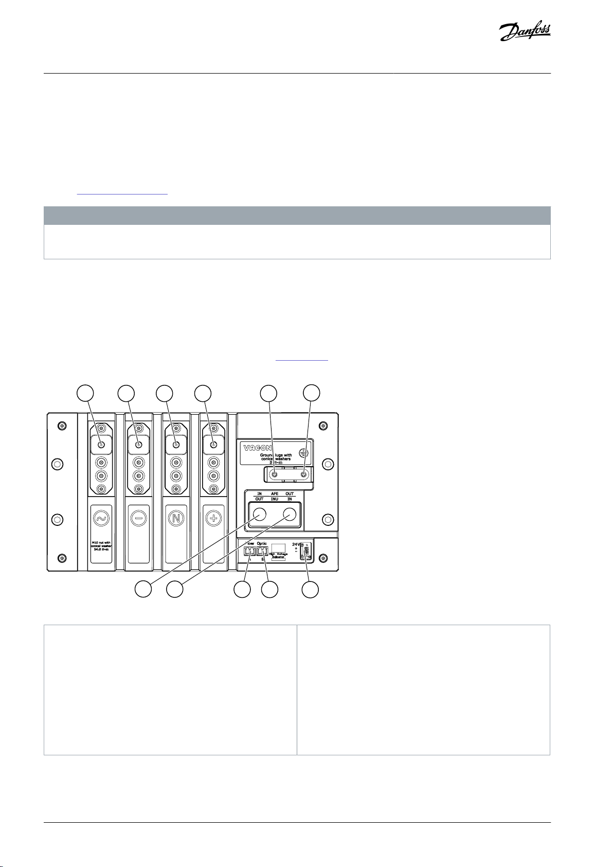
A
~, phase input (AFE) / motor output (INU), size M10
B
- , DC minus, size M10
C
0, DC link neutral point, size M10
D
+, DC plus, size M10
E
Heat sink terminal, size M6
F
Ground terminal, size M6
G
Cooling liquid terminal in (AFE) / out (INU)
H
Cooling liquid terminal in (INU) / out (AFE)
I
Optical fiber A
J
Optical fiber B
K
24 V supply for control
VACON® 3000 Enclosed Drive
Operating Guide
Electrical Installation
6.6 Main Circuit Breaker Installation
Install a main circuit breaker for the short-circuit protection of the AC drive. Use, for example, a fast vacuum circuit breaker. When
selecting the size of the mains circuit breaker, refer to the available short circuit power, continuous current, and supply voltage.
The VACON® 3000 AFE drive has a maximum short-circuit current of 31.5 kA. The operation time of the circuit breaker must not be
longer than 4 cycles (50 Hz: 80 ms, 60 Hz: 67 ms).
The function of the circuit breaker is to give short-circuit protection. For ground fault protection, install a protection relay and resistors.
See also 2.5 Main Circuit Breaker.
N O T I C E
CONNECTION TO ARC FLASH PROTECTION
Connect the circuit breaker to the arc flash detection system in the AC drive cabinet.
6.7 Cabling of the Power Modules
6.7.1 Phase Module L20/L30 Terminals
To make access and installation easy, all terminals are located in the front of the phase modules. Phase, DC, neutral, and ground
terminals have sufficient space between them and creepage walls on each side. To make the terminals compatible with different
cable lugs, the terminals can be changed by removing screws from the front.
See the functions of the AFE/INU phase module terminals in Illustration 23. If the phase module operates as an AFE or INU, some of
the terminals have different functions.
Illustration 23: AFE/INU Phase Module Terminals
6.7.2 DFE Power Module Terminals
In the DFE power module, all terminals are at the front of the module, except the AC input terminals, which are at the back of the
module. DC, neutral, and ground terminals have sufficient space between them and creepage walls on each side. To make the DC
AQ286660579921en-000101 / DPD0203340 | Danfoss A/S © 2021.09

A
I
K
L
M
N
O
P
G
H
B C
F
E
D
J
e30bi551.10
A
- , DC minus, size M10
B
N, DC neutral, size M10
C
+, DC plus, size M10
D
Optical fibers
E
Optical fibers A and B
F
24 V supply
G
Cooling liquid terminal in
H
Cooling liquid terminal out
I
Heat sink terminal, size M6
J
Ground terminal, size M6
K
1L1, phase input
L
1L2, phase input
M
1L3, phase input
N
2L1, phase input
O
2L2, phase input
P
2L3, phase input
VACON® 3000 Enclosed Drive
Operating Guide
terminals compatible with different cable lugs, the terminals can be changed by removing screws from the front. The AC terminals
have knife type busbar connections for 10 mm (0.39 in) thick busbars.
The functions and locations of the DFE power module terminals are shown in Illustration 24.
Electrical Installation
Illustration 24: Terminals in the Front (left) and Back (right) of the DFE Power Module
6.7.2.1 DFE Control Terminals
The DFE power module has specific terminals for controlling the crowbar circuit in the module. Optical fiber terminals A and B are
for Powerbus connection to the auxiliary I/O board.
The optical crowbar circuit control connectors:
•
T: Crowbar TX
•
R: Crowbar RX
•
O: Crowbar fire out
•
FIRE: External crowbar fire in
•
GOOD: Main circuit breaker enable out
To avoid unintentional crowbar firing, protect unused optical connectors with matching covers.
N O T I C E
AQ286660579921en-000101 / DPD02033 | 41Danfoss A/S © 2021.09
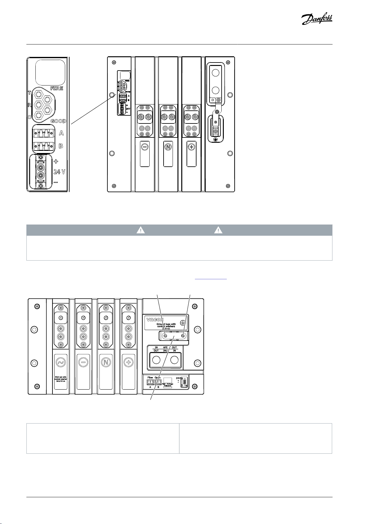
e30bi563.10
AB
C
e30bg718.10
A
Grounding terminal
B
Heat sink terminal
C
Heat sink grounding jumper
VACON® 3000 Enclosed Drive
Operating Guide
Illustration 25: Control Terminals of the DFE Power module
6.7.3 Power Module Grounding
Electrical Installation
C A U T I O N
GROUNDING THE HEAT SINK
In the power modules, do not remove the grounding jumper between the heat sink terminal and the ground terminal.
-
Ground all the power modules. Also the heat sinks of all power modules must be grounded. Make sure that the grounding jumper is
connected between the heat sink terminal and the ground terminal (see Illustration 26).
Illustration 26: AFE/INU Phase Module Grounding Terminals and Jumper
AQ286660579921en-000101 / DPD0203342 | Danfoss A/S © 2021.09

A
B
C
e30bi550.10
A
Grounding terminal
B
Heat sink terminal
C
Heat sink grounding jumper
A
B
C
e30bg719.10
A
Grounding terminals
B
Grounding connection busbar
C
Grounding busbar
VACON® 3000 Enclosed Drive
Operating Guide
Illustration 27: DFE Power Module Grounding Terminals and Jumper
Electrical Installation
Use a busbar to connect all the grounding terminals of the phase modules and power modules to the same grounding busbar. See
the example in Illustration 28.
Illustration 28: Phase Module Grounding Connection Busbar Example
6.7.4 DC-Link Connections
The VACON® 3000 power modules and DC capacitors for DFE have three DC terminals: plus (+), minus (-) and neutral (N).
Busbars or cables can be used to make the DC-link connections.
DC-link connections in AFE drives
AQ286660579921en-000101 / DPD02033 | 43Danfoss A/S © 2021.09
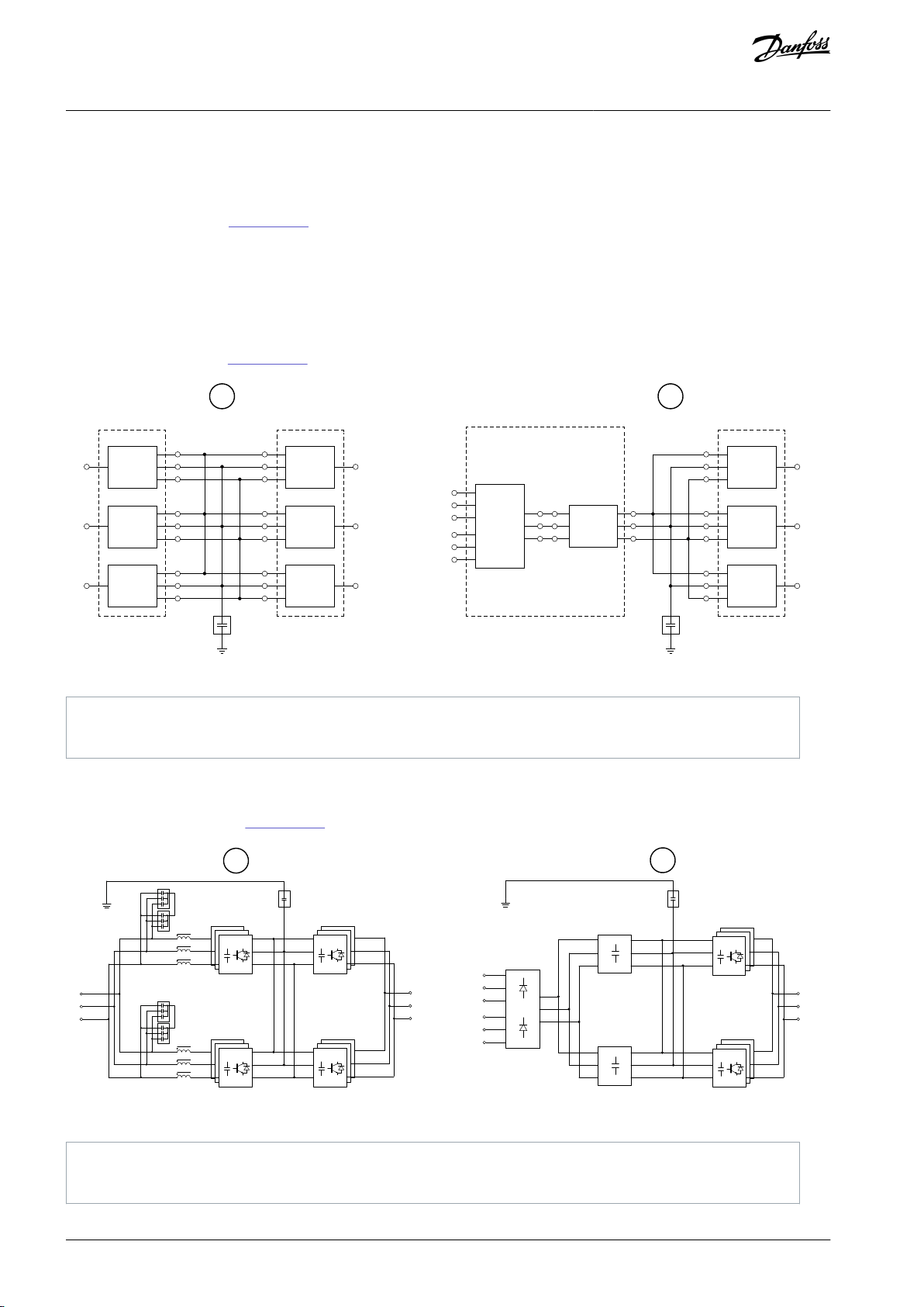
L1
PE
CCM
PE
CCM
+
0
-
~
+
0
-
~
+
0
-
~
L2
L3
PCU
AFE
PCU
PCU
U
V
W
~
~
~
~
~
~
~
~
+
0
-
+
0
-
+
0
-
~
PCU
INU
PCU
PCU
+
+
00
--
+
0
-
CDC
DFE
U
V
W
~
~
+
0
-
+
0
-
+
0
-
~
PCU
INU
PCU
PCU
1L1
1L2
1L3
PCU
2L1
2L2
2L3
A B
e30bg720.11
A
AFE drive
B
12-pulse drive
CCM
+
-
o
+
-
o
+
-
o
+
-
o
3 x PCU 3 x PCU 3 x PCU
3 x PCU 3 x PCU 3 x PCU
CDC
CDC
+
-
o
DFE
PE
PE
CCM
LCV
+
-
o
+
-
o
2 x CSH
2 x CSH
LCV
+
-
o
+
-
o
U
V
W
U
V
W
L1
L2
L3
1L1
1L2
1L3
2L1
2L2
2L3
A
B
e30bg721.11
+
-
o
+
-
o
A
AFE drive
B
12-pulse drive
VACON® 3000 Enclosed Drive
Operating Guide
•
Connect the output DC terminals of the AFE phase modules to the DC-input terminals of the INU phase modules.
•
Connect the DC-plus terminals of the phase modules together and the DC-minus terminals of the phase modules together.
•
Connect the DC-link neutral points of the phase modules and ground them through the common-mode capacitor (CCM).
•
See circuit diagram A in Illustration 29.
Electrical Installation
DC-link connections in 12-pulse drives
•
Connect the output DC terminals of the DFE power module to the plus (+), minus (-), and neutral (N) terminals of the DC capacitor for DFE (CDC).
•
Connect the DC terminals of the INU phase modules to the plus (+), minus (-), and neutral (N) terminals of the CDC.
•
Ground the DC-link neutral point through the common-mode capacitor (CCM).
•
See circuit diagram B in Illustration 29.
Illustration 29: DC-Link Connections in VACON® 3000 Drives
DC-link connections in VACON® 3000 drives with parallel power circuits
•
Connect the plus, minus, and neutral terminals of the parallel DC links.
•
See the circuit diagrams in
Illustration 30.
Illustration 30: DC-Link Connection Examples for VACON® 3000 Drives with Parallel Power Circuits
AQ286660579921en-000101 / DPD0203344 | Danfoss A/S © 2021.09
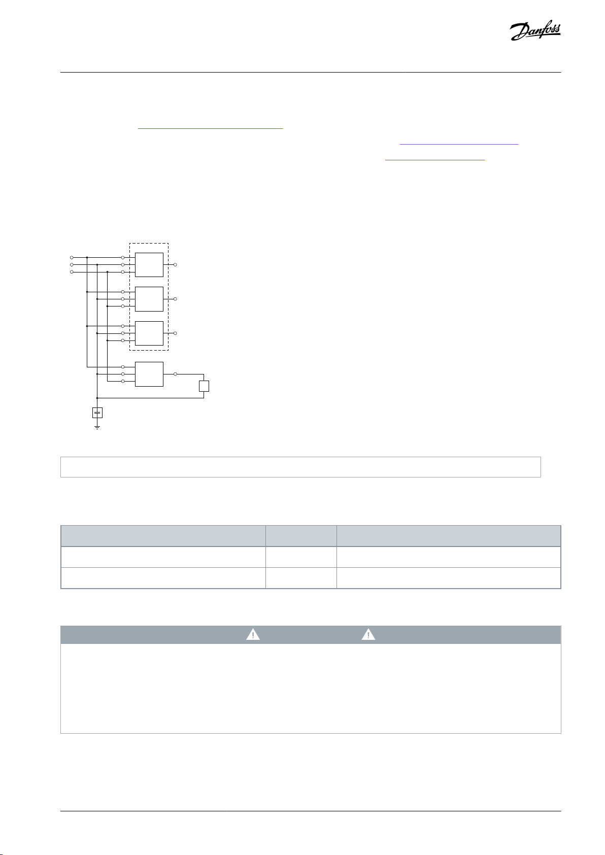
PE
CCM
+
0
-
U
V
W
R
~
~
+
0
-
+
0
-
+
0
-
~
PCU
INU
PCU
PCU
+
0
-
~
+DBCU
e30bg722.10
R
Brake resistor
Terminal
Size
Tightening Torque
Power terminals
M10
24.5 Nm (217 lb-in)
Ground terminals
M6
5 Nm (44 lb-in)
VACON® 3000 Enclosed Drive
Operating Guide
Electrical Installation
6.7.5 Brake Chopper Installation
The brake chopper module is an L20 or L30 phase module. Thus, the electrical and control interface is the same as in AFE and INU
phase modules. See 6.7.1 Phase Module L20/L30 Terminals.
•
Ground the brake chopper module in the same way as the other power modules. See 6.7.3 Power Module Grounding.
•
Make the DC-link connections in the same way as for the INU phase modules. See 6.7.4 DC-Link Connections.
Brake resistor connections
•
Connect the brake resistor between the output terminal (~) of the brake chopper unit (+DBCU) and the DC-link neutral point.
The brake resistor is not included in the brake chopper option (+DBCU) delivery. The resistor can be ordered with a separate order
code.
Illustration 31: DC-Link and Brake Resistor Connections of the Brake Chopper Unit
6.7.6 Terminal Screw Tightening Torque Specifications
Table 7: Power Module Terminal Screw Tightening Torque Specifications
6.7.7 LED Display on the Phase Module
VOLTAGE INDICATION
The voltage indicators on the phase module are not safety approved. Even if the voltage indicators are off, there can be a danger-
ous voltage in the module. A contact with this voltage can lead to death or serious injury.
-
In the front of the phase module, there is a four letter LED display and four LED indicators: BBP, BBN, LED1 and LED2. BBP and BBN
show if there is voltage in the DC link plus and minus busbars. The functions of LED1 and LED2 are not set.
The LED indicators BBP and BBN use the power from the DC link to operate. That is, if the 24 V supply to the phase modules stops,
the LEDs show if the DC link is charged. The LEDs are on when the capacitor DC-link half voltages are >500 V. They start to blink as
the voltage drops to <500 V. If the voltages drop to <25 V, the LEDs turn off.
D A N G E R
Even if the voltage indicators are off, before touching the module:
Short circuit the DC-link terminals and connect them to ground.
Do measurements and make sure that there is no voltage.
AQ286660579921en-000101 / DPD02033 | 45Danfoss A/S © 2021.09

BBP BBN LED1 LED2
A
B
e30bg617.10
A
Four character LED display
B
LED indicators
1
2
3
4
5
6A 6B
e30bg618.10
VACON® 3000 Enclosed Drive
Operating Guide
Illustration 32: LEDs in the front of the phase module
Electrical Installation
LED Display Operation
The phase module start up sequence starts when the connection between the phase module and control unit is disconnected. Usually the start up occurs when 24 V DC is supplied to the module. Also, the start up sequence occurs during a software update.
LED display modes during phase module start up:
•
1. Reset mode: The display is empty.
•
2. Phase module software setup: The phase module sets up local software.
•
3. Phase module communication setup: After the software setup, the phase module enables communication to the control unit.
When the phase module receives the first message from the control unit, the PCU moves to the next mode.
•
4. Control unit setup: Set up between the control unit and the phase module. If the setup is a success, the phase module moves
to the next mode.
•
5. Network setup: The last step in the setup. When the phase module receives approval from the control unit, the phase module
moves to the operation mode.
•
6. Operation: In the operation mode, the LED display view changes at an interval of 3 s. The display changes between the belt
information indicator (6A) and the module information indicator (6B).
Illustration 33: LED Display Modes During Start Up
Belt information: The belt information indicator tells the number of the AFE or INU unit (or belt of three modules) in which the PCU
is installed (see
7.8 Optical Fiber Connections).
The belt information indicator is of type: [ ] [ ] [B] [belt number 1–4].
•
The first two digits are empty.
•
The last two digits show the belt number (B1–B4).
AQ286660579921en-000101 / DPD0203346 | Danfoss A/S © 2021.09
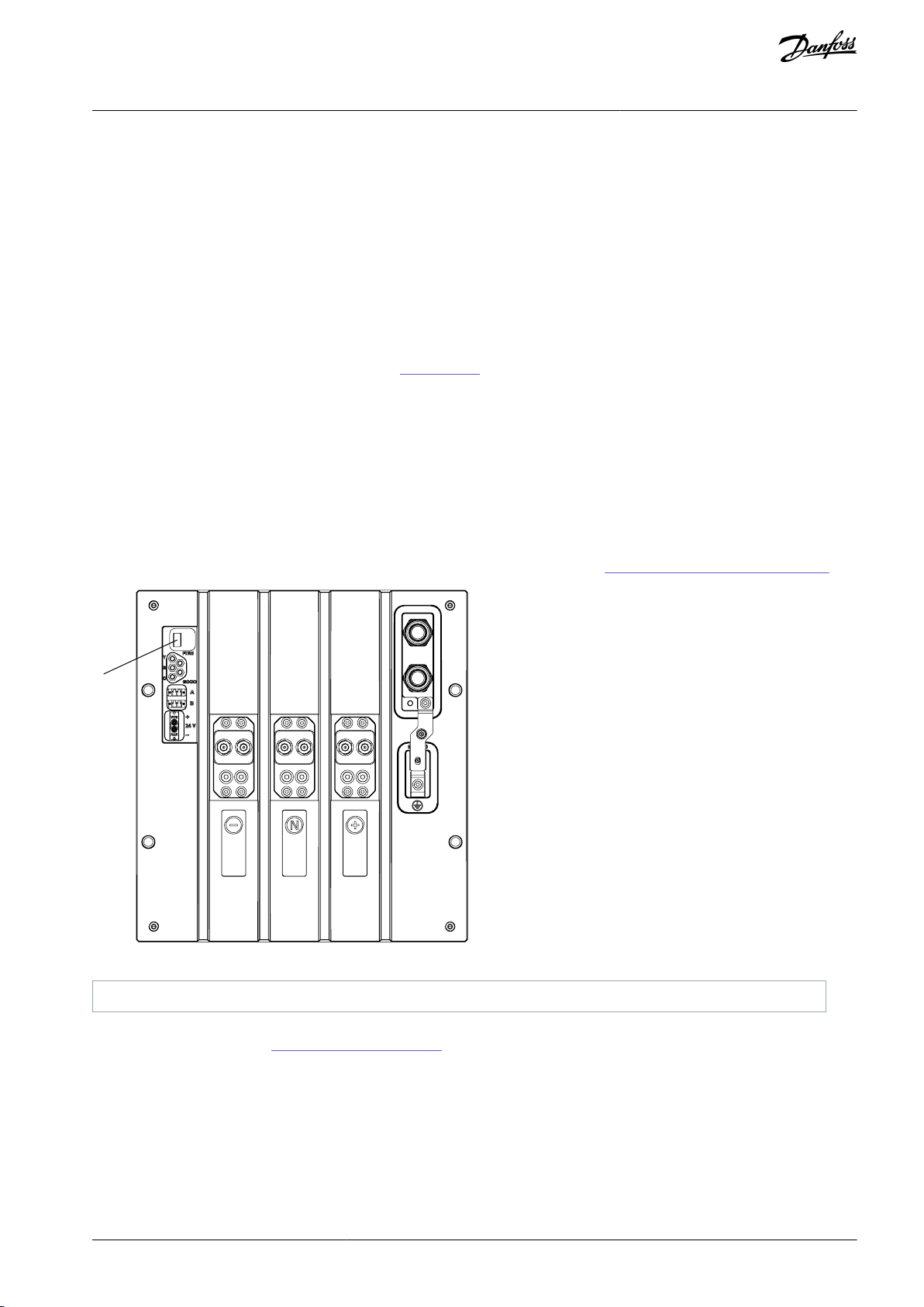
A
e30bi884.10
A
Four character LED display
VACON® 3000 Enclosed Drive
Operating Guide
Module information: The module information indicator tells the identification number of the PCU, the unit type (AFE/INU), and the
phase of the module.
The module information indicator is of type: [PowerID N_] [PowerID _N] [L = AFE, 'blank' = INU] [1, 2, 3 for AFE; U, V, W for INU].
•
The first two digits show the ID of the phase module.
•
The last two digits show the phase.
-
AFE: L1, L2, or L3.
-
INU: _U, _V, or _W.
-
BCU: RA, RB, or RC.
The PowerID is a 2-digit identification number for each phase module. The ID can be mapped directly to the HMI fault source indication.
Belt and module information examples (see 6A/6B in Illustration 33):
•
[ ] [ ] [B] [1] <-> [ ] [2] [ ] [U] = phase module ID 2, U phase INU in belt 1
•
[ ] [ ] [B] [1] <-> [ ] [4] [ ] [W] = phase module ID 4, W phase INU in belt 1
•
[ ] [ ] [B] [3] <-> [1] [0] [ ] [W] = phase module ID 10, W phase INU in belt 3
•
[ ] [ ] [B] [1] <-> [ ] [2] [L] [1] = phase module ID 2, L1 phase AFE in belt 1
•
[ ] [ ] [B] [1] <-> [ ] [4] [L] [3] = phase module ID 4, L3 phase AFE in belt 1
Electrical Installation
6.7.8 LED Display on the DFE Power Module
There is a four character LED display on the front of the DFE power module. The display functions in the same principle as the display on the phase modules, but the shown belt and module information is different. See 6.7.7 LED Display on the Phase Module.
Illustration 34: LEDs on the Front of the DFE Power Module
Belt information: The belt information indicator tells the number of the channel on the control unit to which the power module is
connected, in this case C5 (see 7.8 Optical Fiber Connections).
The belt information indicator is of type: [ ] [ ] [C] [5].
•
The first two digits are empty.
•
The last two digits show the number of the channel.
Module information: The module information indicator tells the identification number of the power module. The number of the
first installed DFE power module is 22, the second is 23, and so on.
The module information indicator is of type: [PowerID N_] [PowerID _N] [ ] [ ].
AQ286660579921en-000101 / DPD02033 | 47Danfoss A/S © 2021.09
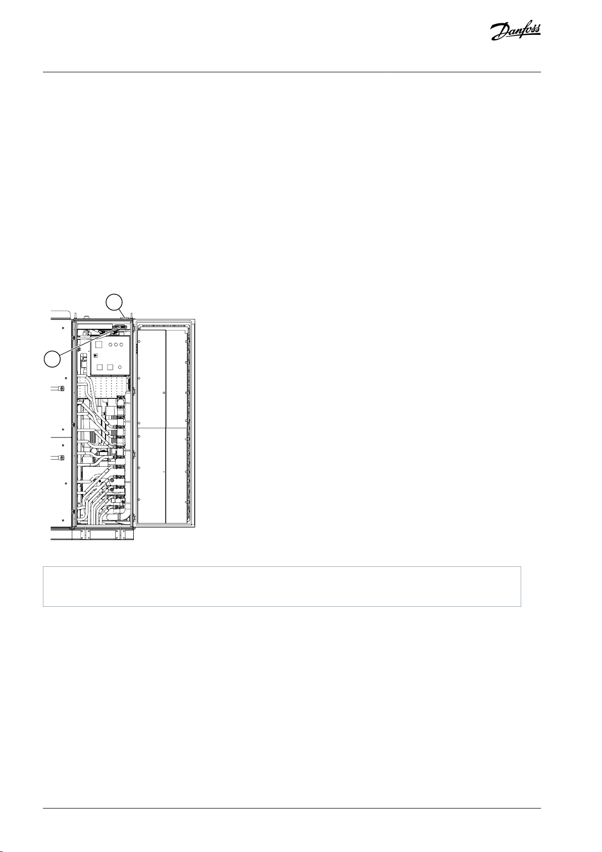
B
A
e30bg974.10
A
Cable entry for low-voltage power supply cables.
B
Low-voltage power supply connectors.
VACON® 3000 Enclosed Drive
Operating Guide
•
The first two digits show the ID of the power module.
•
The last two digits are empty.
Electrical Installation
6.8 Low-Voltage Power Supplies
6.8.1 Low-Voltage Power Supply Connections
Low-voltage power supplies are necessary for the auxiliary components of the VACON® 3000 Enclosed Drive.
•
3-phase 400/480 V, 50/60 Hz supply for the pre-charge unit and the heat exchanger unit. In drives with parallel power circuits, a
separate pre-charge unit is necessary for each parallel circuit. The low-voltage supply to the pre-charge units must be able to
supply a power of 10 kVA for each pre-charge unit.
•
1-phase 120 V, 50/60 Hz supply for the control units and auxiliary components in the LV section of the cabinet.
•
1-phase 120 V, 50/60 Hz supply for the auxiliary components in the MV section of the cabinet.
Make sure that the input AC voltage level selection for the pre-charge unit is correct.
Ground the cable shields of the LV supply cables.
Illustration 35: The Location of the Low-Voltage Cable Entry and the Power Supply Connectors
AQ286660579921en-000101 / DPD0203348 | Danfoss A/S © 2021.09

A
e30bg975.10
A
Precharge unit
VACON® 3000 Enclosed Drive
Operating Guide
Electrical Installation
6.8.2 Safety Notes for the Precharge Unit
D A N G E R
SHOCK HAZARD FROM THE PRECHARGE UNIT
The precharge unit can supply dangerous high voltages from its low-voltage source (215 V to 480 V AC). A contact with this volt-
age can lead to death or serious injury.
Do not try to energize the precharge unit before the system installation is completed!
-
Do not bypass the control unit and energize the precharge unit!
Make sure that correct lock out and tag out procedures are applied to the low-voltage input of the precharge unit.
C A U T I O N
RISK OF OVERHEATING
Successive precharge operations can overheat the transformer of the precharge unit.
To allow the transformer enough time to cool down, ensure a minimum of 30 minutes between successive precharge opera-
-
tions.
The correct selection of the voltage selection board prevents the application of incorrect voltage to the transformer input.
If there is a fault condition, the 2-pole circuit breaker on top of the precharge unit opens. The breaker opens only in fault conditions
in which inspection or maintenance is necessary.
The control unit monitors the DC-link voltage during the precharge sequence and if it senses an unusual condition, stops the se-
quence. Because of the monitoring, do not bypass these protection steps during the commissioning or troubleshooting of the drive.
Precharge timeout:
•
The control unit automatically limits the frequency of start ups to a safe value.
6.8.3 Location of the Precharge Unit
The precharge unit or units are typically installed at the top of the output section of the enclosed drive. The location can differ
depending on the drive type and configuration.
Illustration 36: The Location of the Precharge Unit
6.9 Safety Functions
The information in this section is valid only if the drive is equipped with the STO option (+QSTO).
AQ286660579921en-000101 / DPD02033 | 49Danfoss A/S © 2021.09

VACON® 3000 Enclosed Drive
Operating Guide
Electrical Installation
6.9.1 Safe Torque Off (STO)
Safe Torque Off (STO) is a hardware-based safety function to prevent the drive from generating torque on the motor shaft. The STO
safety function has been designed for use in accordance with the following standards:
•
EN 61800-5-2 STO SIL3
•
ENISO 13849-1 PL “e” Category 4
•
EN 62061 SILCL3
•
IEC 61508 SIL3
•
The function also corresponds to an uncontrolled stop in accordance with stop category 0, EN 60204-1.
The STO function is not the same as the prevention of unexpected start-up function. For fulfilling those requirements, more external
components are required according to appropriate standards and application requirements. Required external components can be
for example:
•
Appropriate lockable switch
•
A safety relay providing a reset function
6.9.2 Safe Stop 1 (SS1)
The SS1 safety function is realized in compliance with type C of the drives safety standard EN 61800-5-2 (Type C: "The PDS(SR) initiates the motor deceleration and initiates the STO function after an application specific time delay").
The SS1 safety function has been designed for use in accordance with the following standards:
•
EN 61800-5-2 Safe Stop 1 (SS1) SIL3
•
EN ISO 13849-1 PL"e" Category 4
•
EN 62061: SILCL3
•
IEC 61508 SIL3
•
The function also corresponds to a controlled stop in accordance with the stop category 1, EN 60204-1.
6.9.3 Safety Considerations
Designing of safety-related systems requires special knowledge and skills. Only qualified personnel are permitted to install and set
up the STO functionality.
The use of STO or other safety functions does not in itself ensure safety. An overall risk evaluation is required to make sure that the
commissioned system is safe. The safety devices must be correctly incorporated into the entire system. The entire system must be
designed in compliance with all relevant standards within the field of industry.
Standards such as EN 12100 (Part 1/Part 2) and ISO 14121-1 provide methods for designing safe machinery and for carrying out a
risk assessment.
The information in this manual provides guidance on the use of the STO safety function together with the VACON® 3000 Enclosed
Drive. This information is in compliance with accepted practice and regulations at the time of writing. However, the end product/
system designer is responsible for ensuring that the system is safe and in compliance with relevant regulations.
The STO function does not electrically isolate the drive output from the mains supply. If electrical work is to be carried out on the
drive, the motor or the motor cabling, the drive has to be isolated from the mains supply. Use, for example, an external mediumvoltage disconnecting switch (optionally as part of the main circuit breaker, see 6.6 Main Circuit Breaker Installation). In addition, the
grounding switch must be closed or an alternative grounding according to applicable standards must be provided (see 8.2 Operat-
ing the Grounding Switch).
6.9.3.1 Diagnostic Test
Performing a diagnostic test is mandatory. The achievable SIL performance level/category for STO/SS1 depends on the testing interval.
AQ286660579921en-000101 / DPD0203350 | Danfoss A/S © 2021.09

Test/ diagnostic interval
(1)
EN 61800-5-2
ENISO 13849-1
EN 62061
1 day
SIL3
PL “e” Category 4
SILCL3
3 months
SIL3
PL “e” Category 3
SILCL3
1 year
SIL2
PL “d” Category 3
SILCL2
Frequency
Time
SS1
request
e30bi927.10
Time delay
Safe Torque Off (STO)
0
f
actual
Motor
deceleration
VACON® 3000 Enclosed Drive
Operating Guide
Table 8: SIL Performance Level/Category Based on Diagnostic Test Interval
1
Time between tests.
To perform the test, follow this procedure.
•
Start with a powered-on system. Connection to the MV grid is not required.
•
Press S1 (STO/SS1 button).
•
Wait until the STO diagnostic lamp is continuously on.
•
Reset S1.
•
If available, push reset button S2.
•
The STO diagnostic lamp should go off, and the drive should be operational again after less than 1 minute.
Note: A diagnostic test is also automatically executed as part of any regular STO/SS1 cycle.
Electrical Installation
6.9.4 STO Operating Principle
The STO safety function allows the drive output to be disabled so that the drive cannot generate torque in the motor shaft.
The STO safety function is achieved by stopping the drive operation. The drive operation is stopped by removing the 24 V supply to
the inverter units. When the 24 V supply is removed, the drive stops operation and does not generate torque in the motor shaft.
6.9.5 SS1 Operating Principle
After receiving a safe stop command, the motor starts decelerating and the SS1 safety function initiates the STO function after a
user-set time delay.
Illustration 37: The Principle of Safe Stop 1 (EN 61800-5-2, SS1 Type C)
The system designer/user is responsible for understanding and setting the time delay of the safety relay, as it is process/machine
dependent.
•
The time delay of the relay must be set to a greater value than the deceleration time of the drive. If there is a single failure or
malfunctioning of the drive system, the drive may not ramp down as requested, but is always put to a safe STO state after the
configured time delay of the relay. The motor deceleration time is process/machine dependent.
•
The stop function of the drive must be correctly set for the process/machine. Activating the SS1 safety function must execute
the configured stop in the drive, using the undelayed relay output signal "SS1 NOT ACTIVATED". In the application software, it is
recommended to use the "Quick Stop" functionality for this purpose.
AQ286660579921en-000101 / DPD02033 | 51Danfoss A/S © 2021.09
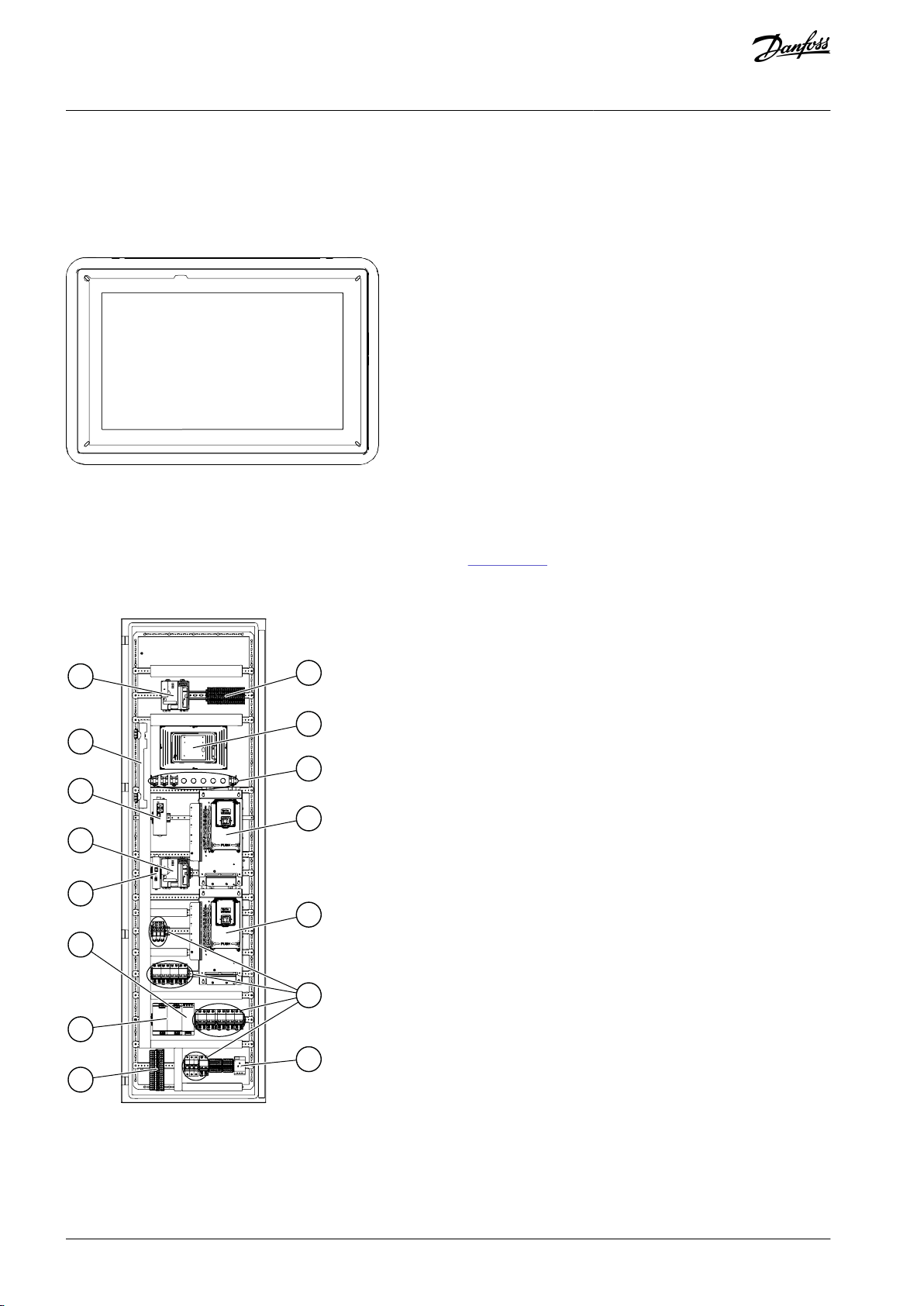
e30bg977.10
B
C
D
E
J
I
H
A
H
N
K
L
M
G
F
e30bg976.10
VACON® 3000 Enclosed Drive
Operating Guide
Control Connections
7 Control Connections
7.1 Control Interface
When the drive is connected to the mains, it must be possible to monitor the drive, reset faults, and set parameters to the drive
without opening the cabinet. These actions can all be done with the door-mounted PLC touch screen.
Illustration 38: PLC Touch Screen on the Cabinet Door
7.2 The Control Compartment of the Enclosed Drive
VACON® 3000 Enclosed Drive has a control compartment, a separate section which includes the control units and other auxiliary
components. The components of the control compartment shown in Illustration 39 can differ depending on the drive type and
configuration. For example, the AFE drive has two control units and the 12-pulse drive has one. Drives with the brake chopper option (+DBCU) also have a control unit for the brake chopper.
Illustration 39: Components in the Control Compartment
AQ286660579921en-000101 / DPD0203352 | Danfoss A/S © 2021.09

A
AFE control unit
B
INU control unit
C
Diode module for the 24 V power supplies
D
Fiber optic converter
E
24 V power supplies for the control units
F
Terminals for control connections and auxiliary devicesGMCBs and relays for the auxiliary devices
H
PLCIIndustrial Ethernet switch
J
Terminals for the PLC
K
PLC touch screen
L
Signal indicator lights and push buttons
M
Cabinet light
N
230 V socket
A
B
C
D
E
F
G
H
I
J
K
L
MN
T
O
P
Q
R
S
T
T
U
U
U
U
e30bg735.10
VACON® 3000 Enclosed Drive
Operating Guide
7.3 Control Unit Components
Control Connections
Illustration 40: The Components of the Control Unit
AQ286660579921en-000101 / DPD02033 | 53Danfoss A/S © 2021.09

A
The control terminals for the default I/O connections
B
The Ethernet connection
C
The relay terminals for 3 relay outputs or 2 relay outputs and a thermistor
D
The option boards
E
DIP switch for the RS485 bus termination
F
DIP switch for the signal selection of analog output
G
DIP switch for the isolation of the digital inputs from
ground
H
DIP switch for the signal selection of analog input 2
I
DIP switch for the signal selection of analog input 1
J
The status indicator of the Ethernet connection
K
Cooling fan
L
The battery for the real-time clock
M
Control unit power supply terminal
N
Encoder terminals (only used in INU control units)
O
Digital inputs and outputs for pre-charge
P
Optical fiber inputs for external breaker enable
Q
Supply voltage feedback
R
Optical fiber interface to phase modules
S
Encoder configuration jumpers
T
Cable clamps
U
Ground points
Color/status of the LED
Status of the drive
Blinking slowly
Ready
Green
Run
Red
Fault
Orange
Alarm
Blinking fast
Downloading software
VACON® 3000 Enclosed Drive
Operating Guide
On delivery of the AC drive, the control unit contains the default control interface (control panel with graphical display). If special
options were selected in the order, the option boards are included loose in the delivery. On the next pages, there is information on
the terminals and general wiring examples.
The control unit can be started with a 24 V DC ±5%, 3 A power source with external overload protection. This voltage is sufficient to
keep the control unit on and for setting the parameters. The measurements of the main circuit (for example, the DC-link voltage,
and the unit temperature) are not available when the drive is not connected to the mains.
The status indicator on the control unit shows the status of the drive. The status indicator is on the control panel, below the keypad,
and it can show five different statuses.
Control Connections
Table 9: Control Unit LED Status Definitions
7.4 Control Unit Cabling
Install the control cables in the low-voltage section of the cabinet. Keep the cables away from high voltages and possible electrical
arcs. Make the control connections between the control units and power units with optical fiber cables.
There are cable entries at the top and bottom of the cabinet.
A VACON® 3000 12-pulse drive has one control unit, the INU control unit. Install all the I/O and relay cables to the INU control unit.
A VACON® 3000 AFE drive has two control units, the AFE control unit and the INU control unit. The I/O and relay cable installation is
application-specific and both the AFE and INU control units can be used.
AQ286660579921en-000101 / DPD0203354 | Danfoss A/S © 2021.09

Terminal
Terminal screw size
Tightening torque
(Nm)
Tightening torque (lbin)
All the terminals of the I/O board and the relay board
M3
0.5
4.5
VACON® 3000 Enclosed Drive
Operating Guide
Control Connections
7.4.1 Selection of the Control Cables
N O T I C E
CABLE SELECTION
Obey regional low-voltage standards in the cable selection.
The control cables must be a minimum of 0.5 mm2 (AWG20) multi-core shielded cables. The terminal wires must be a maximum of
2.5 mm2 (AWG13) for the relay board terminals and other terminals.
Table 10: The Tightening Torques of the Control Cables
7.4.2 Control Unit Terminals
Here is the basic description of the terminals of the default I/O and relay board. The standard I/O board has 22 fixed control terminals and 8 relay board terminals.
Some terminals are assigned for signals that have optional functions that can be used with the DIP switches. For more information,
see 7.5 DIP Switches on the Control Unit.
AQ286660579921en-000101 / DPD02033 | 55Danfoss A/S © 2021.09
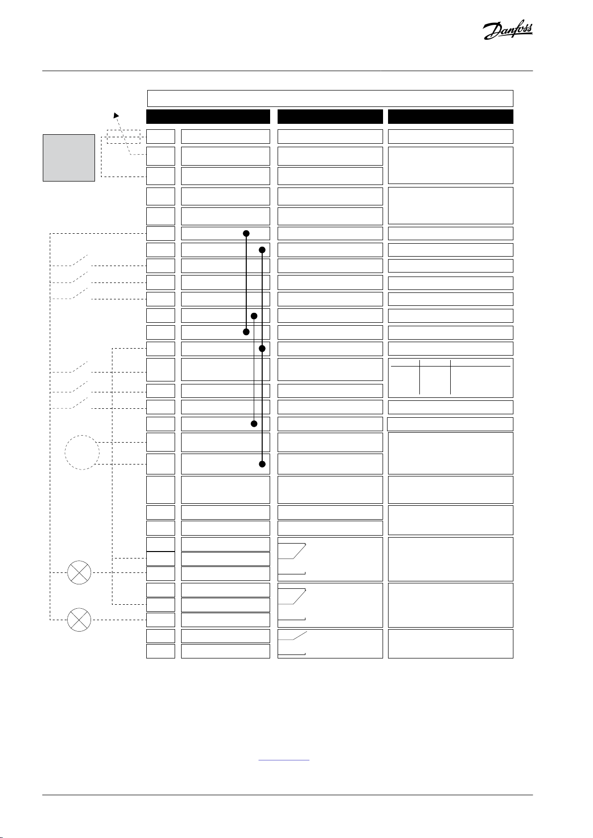
DI4
DI5
Modbus RTU,
N2, BACnet
1
6
2
3
4
5
18
19
30
12
7
13
8
9
10
14
15
16
21
22
23
11
17
A
B
24
25
26
32
33
mA
FAULT
RUN
RUN
AO1-
+24Vin
24Vout
GND
GND
DI1
DI2
DI3
DI4
DI5
DI6
RO1/1 NC
RO1/2 CM
RO1/3 NO
CM
CM
RS485
RS485
RO2/1 NC
RO2/2 CM
RO2/3 NO
RO3/2 CM
RO3/3 NO
Standard I/O board
Terminal Signal Description
+10Vref
AI1+
AI1-
AI2+
AI2-
24Vout
Reference output
Analog input 1+
Analog input 1-
Analog input 2+
Analog input 2-
24 V auxiliary voltage
I/O ground
Digital input 1
Digital input 2
Digital input 3
Digital input 4
Digital input 5
Digital input 6
Common for DI1-DI6
Common for DI1–DI6
24 V auxiliary voltage
I/O ground
Analog output 1+
Analog output 1-
24 V auxiliary
input voltage
Output
frequency
(0...20 mA)
READY
Serial bus, negative
Serial bus, positive
Relay output 1
Relay output 2
Relay output 3
FAULT
Fault reset
AO1+
Frequency reference
(default 0...10 V)
Frequency reference
(Default 4...20 mA)
Start forward
Start reverse
External fault
Freq. ref.
Open
Closed
Open
Closed
Open
Open
Closed
Closed
Analog input 1
Preset Freq. 1
Preset Freq. 2
Preset Freq. 3
Referencepotentiometer
1...10 kΩ
e30bg736.11
VACON® 3000 Enclosed Drive
Operating Guide
Control Connections
Illustration 41: The Signals of the Control Terminals on the Default I/O Board and the Default Control Connections for the VACON® 3000 INU
Application
7.5 DIP Switches on the Control Unit
7.5.1 Selection of Terminal Functions with DIP Switches
Two selections for specified terminals can be done with the DIP switches. The switches have two positions: up and down. See the
location of the DIP switches and the possible selections in Illustration 42.
AQ286660579921en-000101 / DPD0203356 | Danfoss A/S © 2021.09

A B
A
B
C
D
E
AI1
U
I
AO1
U
I
RS485
OFF
ON
AI2
U
I
e30bg737.10
A
The voltage signal (U), 0–10 V input
B
The current signal (I), 0–20 mA input
C
OFFDONEThe RS485 bus termination
The DIP switch
The default position
AI1UAI2IAO1IRS485 bus termination
OFF
VACON® 3000 Enclosed Drive
Operating Guide
Control Connections
Illustration 42: The Selections of the DIP Switches
Table 11: The Default Positions of the DIP Switches
7.5.2 Isolation of the Digital Inputs from Ground
It is possible to isolate from ground the digital inputs (terminals 8–10 and 14–16) on the standard I/O board. To do this, change the
position of a DIP switch on the control board.
AQ286660579921en-000101 / DPD02033 | 57Danfoss A/S © 2021.09

A
B
C
e30bg738.10
A
The digital inputs
B
Floating
C
Connected to ground (default)
VACON® 3000 Enclosed Drive
Operating Guide
Illustration 43: Change the Position of This Switch to Isolate the Digital Inputs from Ground
Control Connections
7.6 Fieldbus Connection
7.6.1 Fieldbus Terminals
The drive can be connected to fieldbus with an RS485 or an Ethernet cable.
•
If an RS485 cable is used, connect it to terminals A and B of the default I/O board.
•
If an Ethernet cable is used, connect it to the Ethernet terminal.
In a VACON® 3000 AFE drive, connect the fieldbus to both the AFE and INU control units.
AQ286660579921en-000101 / DPD0203358 | Danfoss A/S © 2021.09

C
D
F
A
B
E
e30bg739.10
A
RS485 terminal A = Data -
B
RS485 terminal B = Data +
C
RS485 DIP switch
D
The Ethernet terminal
E
The control terminals
F
Cable clamps
Item
Description
Plug type
Shielded RJ45 plug, maximum length 40 mm (1.57 in)
Cable type
CAT5e STP
Cable length
Maximum 100 m (328 ft)
VACON® 3000 Enclosed Drive
Operating Guide
Control Connections
Illustration 44: The Ethernet and RS485 Connections
7.6.2 Using Fieldbus through an Ethernet Cable
Table 12: Ethernet Cable Data
Ethernet Cabling
1.
Connect the Ethernet cable to its terminal.
See more in the installation guide of the used fieldbus.
AQ286660579921en-000101 / DPD02033 | 59Danfoss A/S © 2021.09
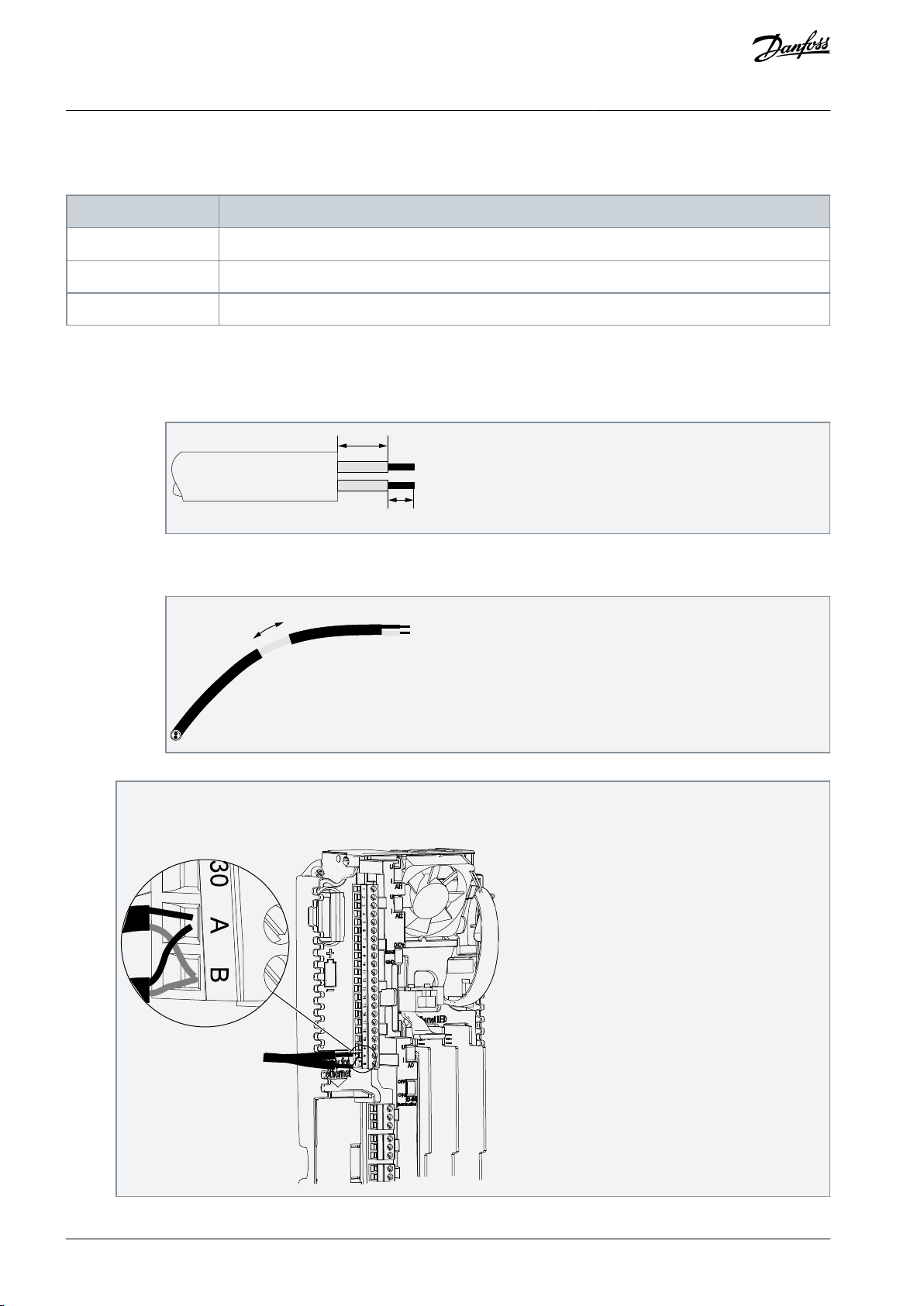
Item
Description
Plug type
2.5 mm2 (AWG13)
Cable type
STP (shielded twisted pair), Belden 9841 or similar
Cable length
So that it agrees with the fieldbus. See the fieldbus manual.
10
5
e30bg841.10
15 mm
e30bg842.10
e30bg843.10
VACON® 3000 Enclosed Drive
Operating Guide
7.6.3 Using Fieldbus through an RS485 Cable
Table 13: RS485 Cable Data
RS485 Cabling
1.
Remove approximately 15 mm (0.59 in) of the gray shield of the RS485 cable. Do this for the two fieldbus cables.
a.
Strip the cables for approximately 5 mm (0.20 in) to put them in the terminals. Do not keep more than 10 mm (0.39
in) of the cable outside the terminals.
Control Connections
b.
Strip the cable at such a distance from the terminal that it can be attached to the frame with the grounding clamp
for the control cable. Strip the cable at a maximum length of 15 mm (0.59 in). Do not remove the aluminum shield
of the cable.
2.
Connect the cable to the default I/O board of the drive, in terminals A and B.
•
A = negative
•
B = positive
AQ286660579921en-000101 / DPD0203360 | Danfoss A/S © 2021.09
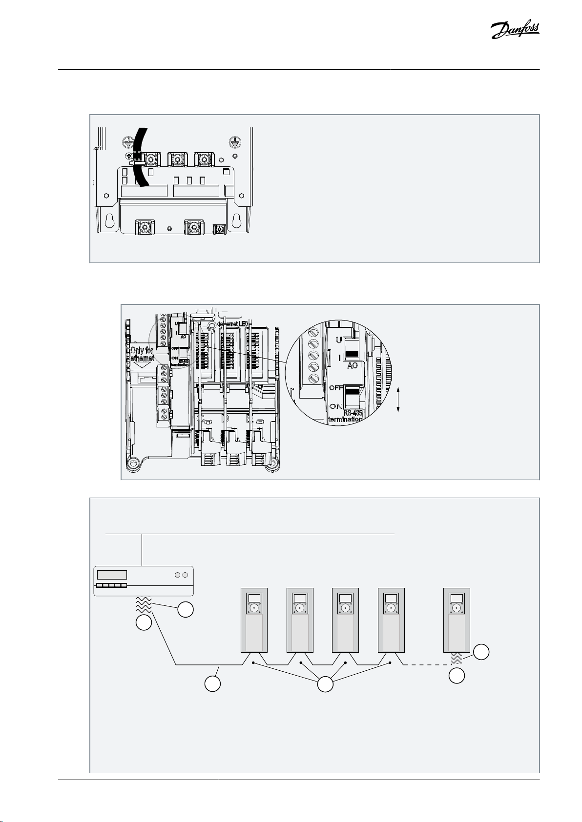
e30bg844.10
e30bg845.10
D
D
E
A
C
B
e30bg846.10
VACON® 3000 Enclosed Drive
Operating Guide
3.
Attach the shield of the cable to the frame of the drive with a grounding clamp for the control cable to make a grounding
connection.
Illustration 45: Grounding the Cable with a Grounding Clamp
4.
If the drive is the last device on the fieldbus line, set the bus termination. Set the bus termination for the first and the last
device of the fieldbus line. It is recommended that the first device on the fieldbus is the master device.
a.
Find the DIP switches on the left side of the control unit of the drive.
Control Connections
b.
Set the DIP switch of the RS485 bus termination to the ON position.
The termination resistors are placed at both ends of the fieldbus line to decrease signal reflections on the line.
Biasing is built in the bus termination resistor. The termination resistance is 220 Ω.
Illustration 46: Setting the Bus Termination for a Fieldbus Line
AQ286660579921en-000101 / DPD02033 | 61Danfoss A/S © 2021.09

A
The termination is activated
B
The termination is deactivated
C
The termination is activated with a DIP
switch
D
The bus termination. The resistance is 220
Ω.EThe fieldbus
OPT
dv
A
e30bg847.10
A
The slot coding
VACON® 3000 Enclosed Drive
Operating Guide
Control Connections
N O T I C E
LOSS OF TERMINATION RESISTANCE
If the last device on the fieldbus line is powered down, the termination resistance is lost. The loss of termination resist-
ance causes signal reflections on the line, which can disrupt the fieldbus communication.
Do not power down the last device on the fieldbus line while the fieldbus is active.
-
7.7 Option Board Installation
W A R N I N G
SHOCK HAZARD FROM CONTROL TERMINALS
The control terminals can have a dangerous voltage also when the drive is disconnected from mains. A contact with this voltage
can lead to injury.
Make sure that there is no voltage in the control terminals before touching the control terminals.
-
N O T I C E
INCOMPATIBLE OPTION BOARDS
It is not possible to install option boards that are not compatible with the drive.
If the installed board is an OPTB or an OPTC option board, make sure that the label on it says "dv" (dual voltage). This marking shows
that the option board is compatible with the drive.
Illustration 47: Label on the Option Board
Installation Procedure
AQ286660579921en-000101 / DPD0203362 | Danfoss A/S © 2021.09

e30bg848.10
B
A
e30bg849.10
A
The slot coding
B
The option slots
VACON® 3000 Enclosed Drive
Operating Guide
1.
To get access to the option slots, open the cover of the control unit.
2.
Install the option board into the correct slot: C, D, or E.
The option board has a slot coding, because of which it is not possible to install the option board in an incorrect slot.
Control Connections
Illustration 48: Installing the Option Boards
3.
Close the cover of the control unit.
7.8 Optical Fiber Connections
The VACON® 3000 drive has a high-speed Powerbus optical fiber interface for internal connections. The control unit has six optical
fiber connections: four for phase modules, one for the connection between the control units and one for an auxiliary board. The two
terminals used for the control of the INU or AFE phase modules are shown in Illustration 49.
AQ286660579921en-000101 / DPD02033 | 63Danfoss A/S © 2021.09

F01
F02
F03
F04
F05
F06
e30bg740.11
F01
Terminal for phase module connections (belt 1)
F02
Terminal for phase module connections (belt 2)
F03
Terminal not used
F04
Terminal not used
F05
Terminal for auxiliary I/O board connection
F06
Terminal not used
A B
A B
A B
PCU
L1 / U
F01
PCU
L2 / V
PCU
L3 / W
e30bg741.10
VACON® 3000 Enclosed Drive
Operating Guide
Illustration 49: Optical Fiber Terminals
Control Connections
Connect the phase modules of each AFE or INU in series (see Illustration 50).
•
Connect the optical fiber from connector A of the phase module L1/U to connector F01 on the control unit.
•
Connect the optical fiber from connector A of the phase module L2/V to connector B on phase module L1/U.
•
Connect the optical fiber from connector A of the phase module L3/W to connector B on phase module L2/V.
Illustration 50: Optical Fiber Connections between Control Unit and Phase Modules
Two parallel AFE or INU units can be connected to one control unit. The first AFE or INU unit (Belt 1, series connection of three phase
modules) is connected to control unit connector F01 and the second (B2) to connector F02.
AQ286660579921en-000101 / DPD0203364 | Danfoss A/S © 2021.09

PCU / L1
PCU / L2
PCU / L3
F01 F02 F03 F04 F05 F06
CH2
CH1
A
B
A
B
A
B
A
B
A
B
A
B
A
B
A
B
A
B
A
B
A
B
A
B
F05 F06
CNU-AFE
F01 F02 F03 F04
CNU-INU
AFE / B1
PCU / L1
PCU / L2
PCU / L3
AFE / B2
PCU / U
PCU / V
PCU / W
INU / B1
PCU / U
PCU / V
PCU / W
INU / B2
AUX I/O
e30bg742.11
VACON® 3000 Enclosed Drive
Operating Guide
Control Connections
If a brake chopper is installed (option +DBCU), there is a separate control unit for the brake choppers. Connect the brake chopper
modules in series as shown in Illustration 51. A maximum of three modules can be connected in series. Brake choppers can also be
connected to the control unit one by one (BCU1 to connector FO1, and BCU2 to FO2).
Illustration 51: Parallel Optical Fiber Connections in an AFE Drive
AQ286660579921en-000101 / DPD02033 | 65Danfoss A/S © 2021.09

F05 F06 F05 F06
F01 F02 F03 F04
CNU-BCU
F01 F02 F03 F04
CNU-INU
PCU / U
PCU / V
PCU / W
INU / B1
PCU / U
PCU / V
PCU / W
INU / B2
PCU
BCU / B1
PCU
BCU / B2
PCU
DFE
e30bi782.10
CH2
CH1
AUX I/O
A
B
A
B
A
B
A
B
A
B
A
B
A
B
A
B
A
B
Item
Specification
Operation temperature
-40...+85°C (-40...+185°F)
Minimum bend radius
25 mm (1 in)
Cable size (outer dimensions)
2.2 x 4.4 mm (0.087 x 0.173 in)
Fiber size
d = 1 mm (0.04 in)
Cover material
Flame resistant PE or PVC
VACON® 3000 Enclosed Drive
Operating Guide
Control Connections
Illustration 52: Parallel Optical Fiber Connections in a 12-pulse Drive with BCU Option
7.8.1 Selection of Optical Fiber Cables
SI-POF duplex cables are recommended for all optical fiber connections. The connector type must be LC duplex. The specifications
in Table 14 are for cables manufactured by Firecomms. The cable assemblies (POF and connectors) are available from Firecomms
resellers with type code FD-XXX-LDB, where XXX is the length of the cable, XXC in centimeters, and XXM in meters.
Table 14: Optical Fiber Cable Specifications
AQ286660579921en-000101 / DPD0203366 | Danfoss A/S © 2021.09

Item
Specification
UL flame resistance
VW-1
Cable standard
Compatible with IEC 60793-2-40 class A4a
Plastic optical fiber type
Duplex optical fiber, 1 mm (0.04 in) high-purity core. The core and cladding are surrounded by a
2.2 mm (0.082 in) polyethylene (PE) jacket.
Firecomms type code: FC-500-0DB
Connector type
Firecomms type code: FP-00C-LD0
Connector standard
Compatible with IEC 61754-20 edition 2
30–40
(1.25–1.5)
25
(1.0)
e30bj243.10
VACON® 3000 Enclosed Drive
Operating Guide
Recommended tools (from FiberFin):
•
LC Duplex crimp tool, 2.60 mm hex, PEW 8 (FiberFin type code: FF-CRMP-LC-WL)
•
Ultra Low Loss finishing tool, LC Connector (FiberFin type code: FF-LC-RZR1)
•
Installer kit, including finishing tool and crimping tool (FiberFin type code: FF-STDLCINST-K)
Control Connections
7.8.2 Making Optical Fiber Cables
The fiber optic cables most likely to need replacement are the ones connected to the phase modules. During the installation or
replacement of modules, it is possible to damage the fiber optic cables accidentally. This procedure describes how to make new
cables.
These tools and equipment are required:
•
Specialized tool kit for fiber optics
-
Wire stripper
-
Wire cutter
-
Crimper tool
•
Fiber optic wire
•
Connectors
For details, see 7.8.1 Selection of Optical Fiber Cables.
Procedure
1.
Cut the required length of fiber optic wire. Use a wire cutter to make sure that the cuts are clean.
2.
Use the stripper tool to strip the wires approximately 25 mm (1 in) at both ends.
Illustration 53: Stripping and Splitting the Cable
3.
Split the wires apart 30–40 mm (1.25–1.5 in) from both ends.
See Illustration 53.
4.
Place a connector into the crimper tool.
AQ286660579921en-000101 / DPD02033 | 67Danfoss A/S © 2021.09
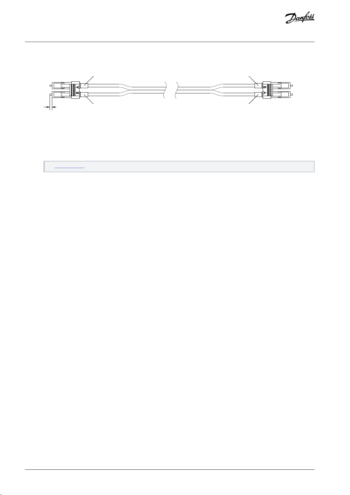
1.6
(0.63)
A
A
B
B
e30bj244.10
VACON® 3000 Enclosed Drive
Operating Guide
5.
Push the fibers into the connector. Make sure that the fibers are fully pushed in. The fibers must come out of the end of the
Control Connections
connector approximately 1.6 mm (0.63 in).
Illustration 54: Installing the Connectors on the Cable
6.
When the wires and connector are fully in position, firmly close the crimper grip.
7.
Install the connector on the other end of the cable. Notice the labels A and B on the connectors. When making the connection for the other end of the wire, B goes to the A slot and A to B.
See Illustration 54.
8.
Check the cable by shining an LED on one end of the cable and verifying that the other end is lit. For example, shine on wire
A on one end, and verify that B is lit on the other end.
7.9 Encoder Interface
The VACON® 3000 control unit includes a 2-encoder interface. The encoder interface is only used in the INU control unit, not in AFE
or BCU control units.
The encoder interface is designed for HTL (High-voltage Transistor Logic) type encoders (voltage output type Push-pull HTL, open
collector output type HTL) which provide input signal levels dependent on the supply voltage of the encoder.
The encoder properties include:
•
Cross-connected optically isolated feedback for good noise limits
•
150 kHz maximum frequency
•
Different encoder line driver voltage levels (24 V, 15 V, 5 V)
•
Different encoder supply voltage levels (+24 V, +15 V) with current limits
•
Differential encoder duplicator option from one of the encoder interfaces
•
Master/follower selection
•
Two qualifier inputs (1Q, 2Q) for position detection or pulse tachometer applications
If absolute encoder functionality is required, contact Danfoss.
AQ286660579921en-000101 / DPD0203368 | Danfoss A/S © 2021.09
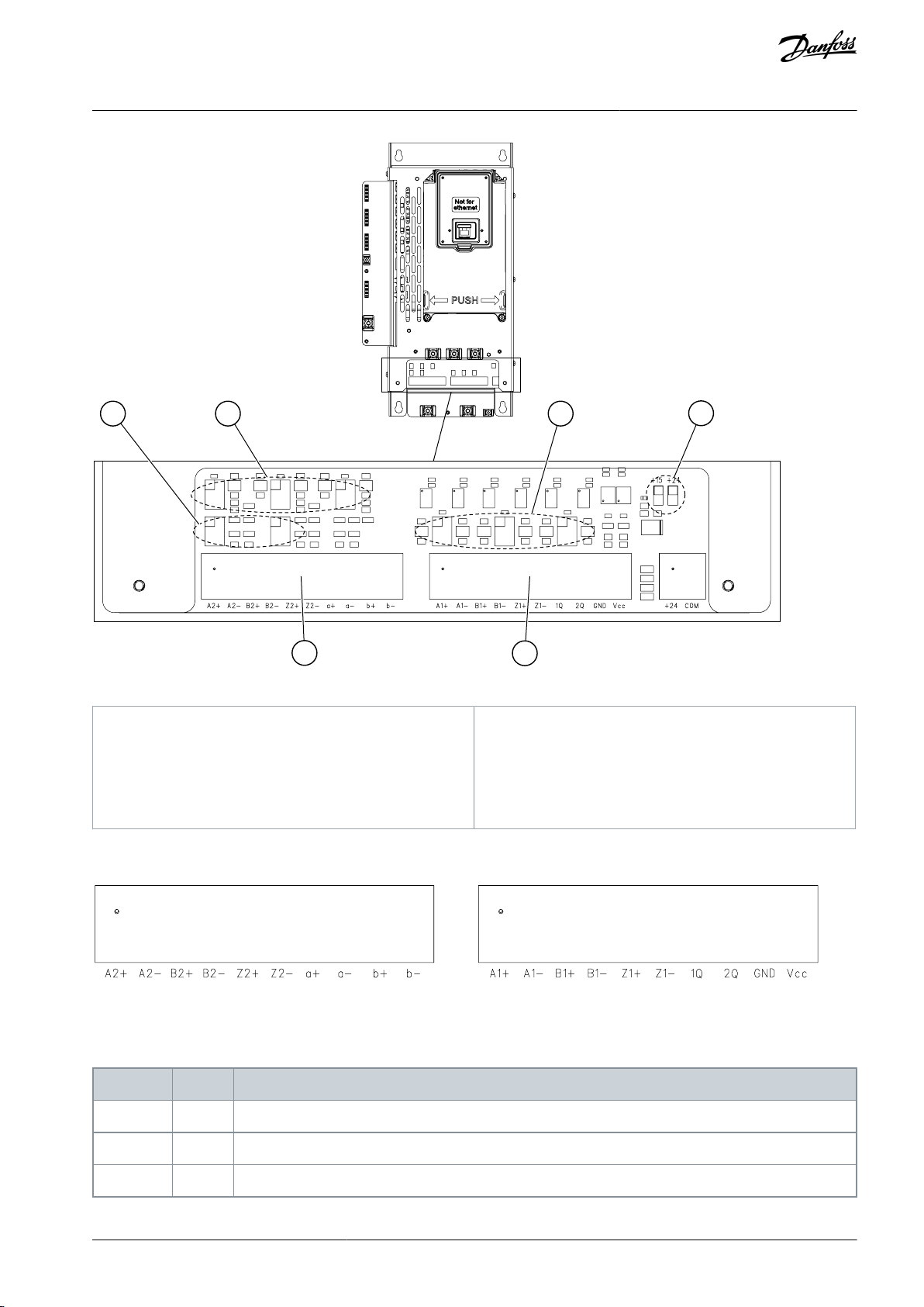
B
DE C
F
A
e30bg744.10
A
Encoder terminal, channel A
B
Encoder terminal, channel B
C
Encoder output voltage selection jumpers, channel
A
D
Encoder output voltage selection jumpers, channel
BEMaster/follower selection jumpers
F
Encoder input voltage selection jumpers
e30bg745.10
Terminal
Signal
Signal Description
1
A1+
Channel A pulse input A1+ (differential); voltage range +5 V…+24 V
2
A1-
Channel A pulse input A1- (differential); voltage range +5 V…+24 V
3
B1+
Channel A pulse input B1+ (differential); voltage range +5 V…+24 V; 90° delay from A1+
VACON® 3000 Enclosed Drive
Operating Guide
Control Connections
Illustration 55: Encoder Interface of the Control Unit
7.9.1 Encoder Terminals and Signals
Illustration 56: Encoder Terminals
Encoder channel A is usable only for motor control.
Table 15: Channel A Terminals and Signals
AQ286660579921en-000101 / DPD02033 | 69Danfoss A/S © 2021.09

Terminal
Signal
Signal Description
4
B1-
Channel A pulse input B1- (differential); voltage range +5 V…+24 V; 90° delay from A1-
5
Z1+
Channel A pulse input Z1+ (differential); voltage range +5 V…+24 V; One pulse/revolution
6
Z1-
Channel A pulse input Z1- (differential); voltage range +5 V…+24 V; One pulse/revolution
71QQualifier/position input; Single-ended signal (to ground)
82QQualifier/position input; Single-ended signal (to ground)
9
GND
Ground for control and inputs 1Q and 2Q
10
Vcc
Encoder supply voltage (selection with jumpers X11 and X15)
Terminal
Signal
Signal Description
1
A2+
Channel B pulse input A2+ (differential); voltage range +5 V…+24 V
2
A2-
Channel B pulse input A2- (differential); voltage range +5 V…+24 V
3
B2+
Channel B pulse input B2+ (differential); voltage range +5 V…+24 V; 90° delay from A2+
4
B2-
Channel B pulse input B2- (differential); voltage range +5 V…+24 V; 90° delay from A2-
5
Z2+
Channel B pulse input Z2+ (differential); voltage range +5 V…+24 V; One pulse/revolution
6
Z2-
Channel B pulse input Z2- (differential); voltage range +5 V…+24 V; One pulse/revolution
7a+Pulse output a+ (differential); Made internally from channel 1 or channel 2 (selection with jumper X21); Output voltage +24 V
8a-Pulse output a- (differential); Made internally from channel 1 or channel 2 (selection with jumper X21); Output voltage +24 V
9b+Pulse output b+ (differential); Made internally from channel 1 or channel 2 (selection with jumper X22); Output voltage +24 V
10b-Pulse output b- (differential); Made internally from channel 1 or channel 2 (selection with jumper X22); Output voltage +24 V
VACON® 3000 Enclosed Drive
Operating Guide
Table 16: Channel B Terminals and Signals
Control Connections
7.9.2 Encoder Jumper Configurations
See the locations of the jumpers in Illustration 57 and the jumper pin sequence in Illustration 58.
The available encoder jumper configurations:
•
Encoder input voltage selection, jumpers X11 and X15, see Table 17.
•
Master/follower selection, jumpers X21 and X22, see Table 18.
•
Encoder output voltage selection for channel A, jumpers X23-X25, see Table 19.
•
Encoder output voltage selection for channel B, jumpers X26-X28, see Table 20.
AQ286660579921en-000101 / DPD0203370 | Danfoss A/S © 2021.09
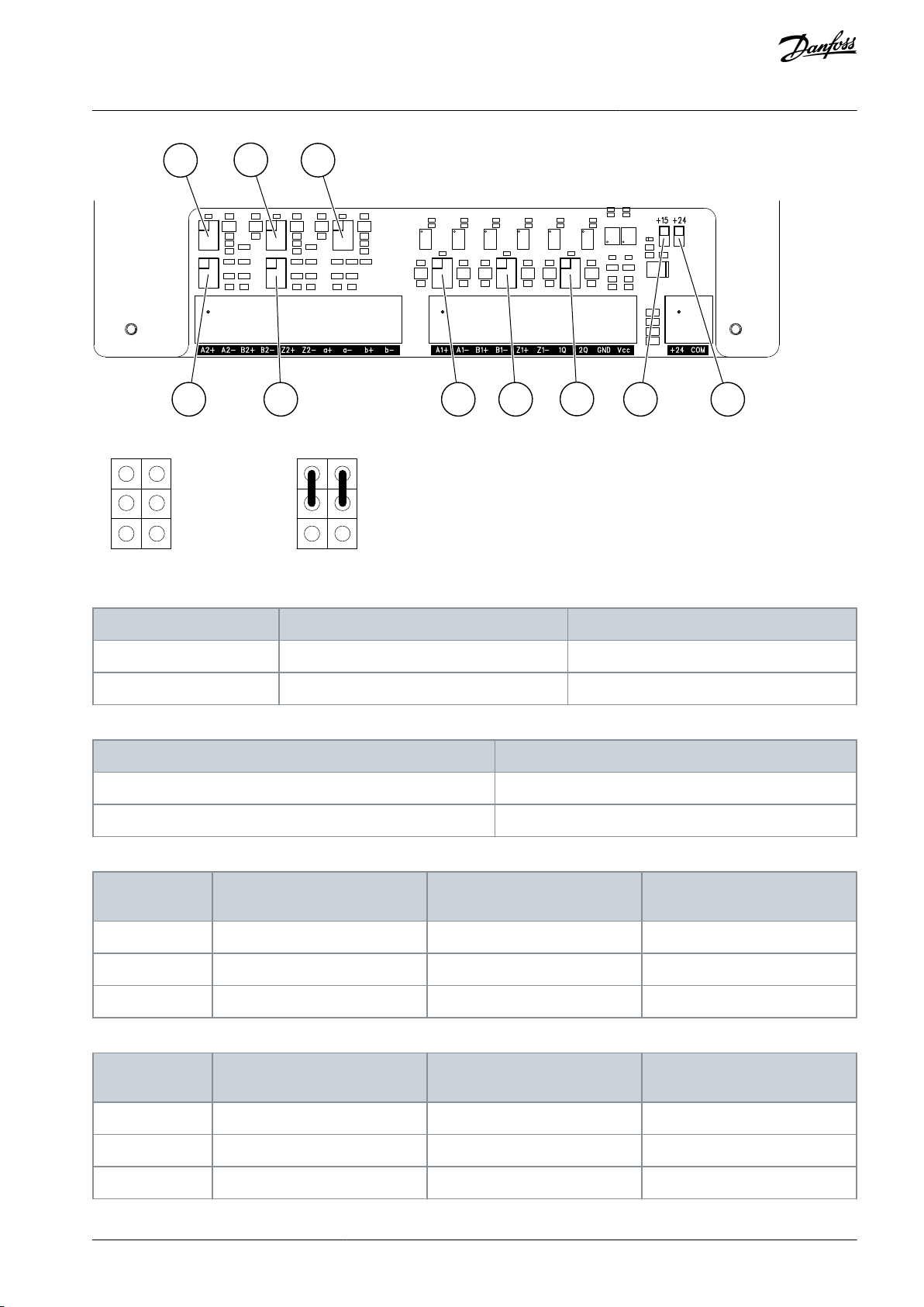
X21 X22
X28
X26
X27
X23 X24
X25
X11 X15
e30bg746.10
1
3
5
2
4
6
1
3
5
2
4
6
e30bg747.10
Jumper Selection
Pins to connect, Jumper X11
Pins to connect, Jumper X15
+15 V (default)
1-2
open
+24 V
open
1-2
Jumper Selection
Pins to connect
Master (default)
3-5 and 4-6
Follower
1-3 and 2-4
Jumper Selection
Pins to connect, Jumper X23 (input A1)
Pins to connect, Jumper X24 (input B1)
Pins to connect, Jumper X25 (input Z1)
+24 V
open
open
open
+15 V (default)
1-3 and 2-4
1-3 and 2-4
1-3 and 2-4
+5 V
3-5 and 4-6
3-5 and 4-6
3-5 and 4-6
Jumper Selection
Pins to connect, Jumper X26 (input A2)
Pins to connect, Jumper X27 (input B2)
Pins to connect, Jumper X28 (input Z2)
+24 V
open
open
open
+15 V (default)
1-3 and 2-4
1-3 and 2-4
1-3 and 2-4
+5 V
3-5 and 4-6
3-5 and 4-6
3-5 and 4-6
VACON® 3000 Enclosed Drive
Operating Guide
Illustration 57: Encoder Jumper Locations
Control Connections
Illustration 58: Jumper Pin Sequence and Connection Example (Pins 1-3 and 2-4 Connected)
Table 17: Encoder Input Voltage Selection, Jumpers X11 and X15
Table 18: Master/Follower Selection, Jumpers X21 and X22
Table 19: Encoder Output Voltage Selection, Channel A
Table 20: Encoder Output Voltage Selection, Channel B
AQ286660579921en-000101 / DPD02033 | 71Danfoss A/S © 2021.09
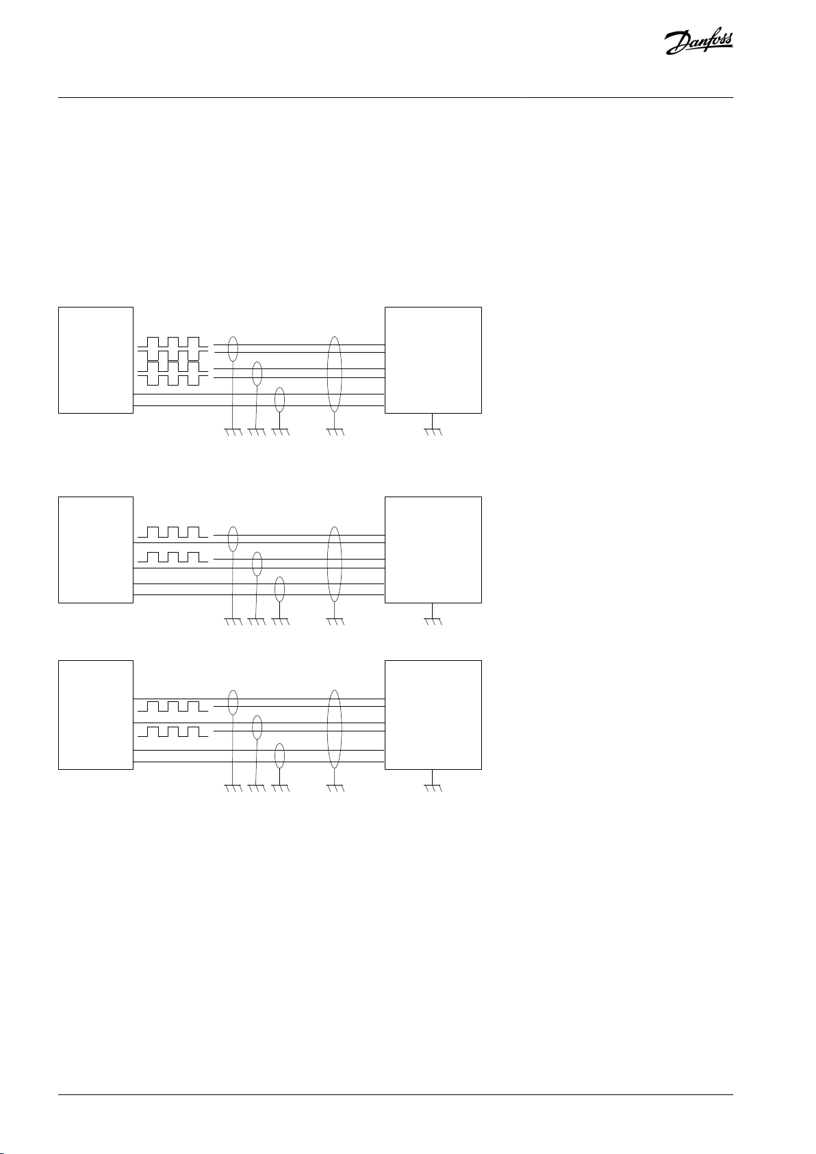
GND
A-
B-
15/24 V
Encoder Control unit
Channel 1
A+
B+
1: A1+
2: A1-
3: B1+
4: B1-
9: GND
10: Vcc
e30bi919.10
GND
GND
GND
+
Encoder Control unit
Channel 1
A+
B+
1: A1+
2: A1-
3: B1+
4: B1-
9: GND
10: Vcc
e30bi920.10
GND
A-
B-
+
Encoder Control unit
Channel 1
+
+
1: A1+
2: A1-
3: B1+
4: B1-
9: GND
10: Vcc
e30bi921.10
VACON® 3000 Enclosed Drive
Operating Guide
Control Connections
7.9.3 Encoder Connection
Ground the encoder cable shields only at the AC drive end to avoid circulating current in the shield. Isolate the shield at the encoder
end.
If possible, use double shielded cable for encoder connection.
A high pulse frequency combined with a high cable capacitance places a considerable load on the encoder. Therefore, apply as low
a voltage as possible for the encoder supply. Use +15 V encoder voltage input, if allowed in the voltage range specification of the
encoder.
If external voltage supply is used, connect the ground of the external supply to terminal 9 in channel A of the encoder interface and
to the encoder ground.
Differential Connection
Illustration 59: HTL Type Encoder Connection with Differential Inputs
Single-ended Connection
Illustration 60: HTL Type Encoder Connection (Open Source) with Single-ended Inputs
Illustration 61: HTL Type Encoder Connection (Open Collector) with Single-ended Inputs
AQ286660579921en-000101 / DPD0203372 | Danfoss A/S © 2021.09
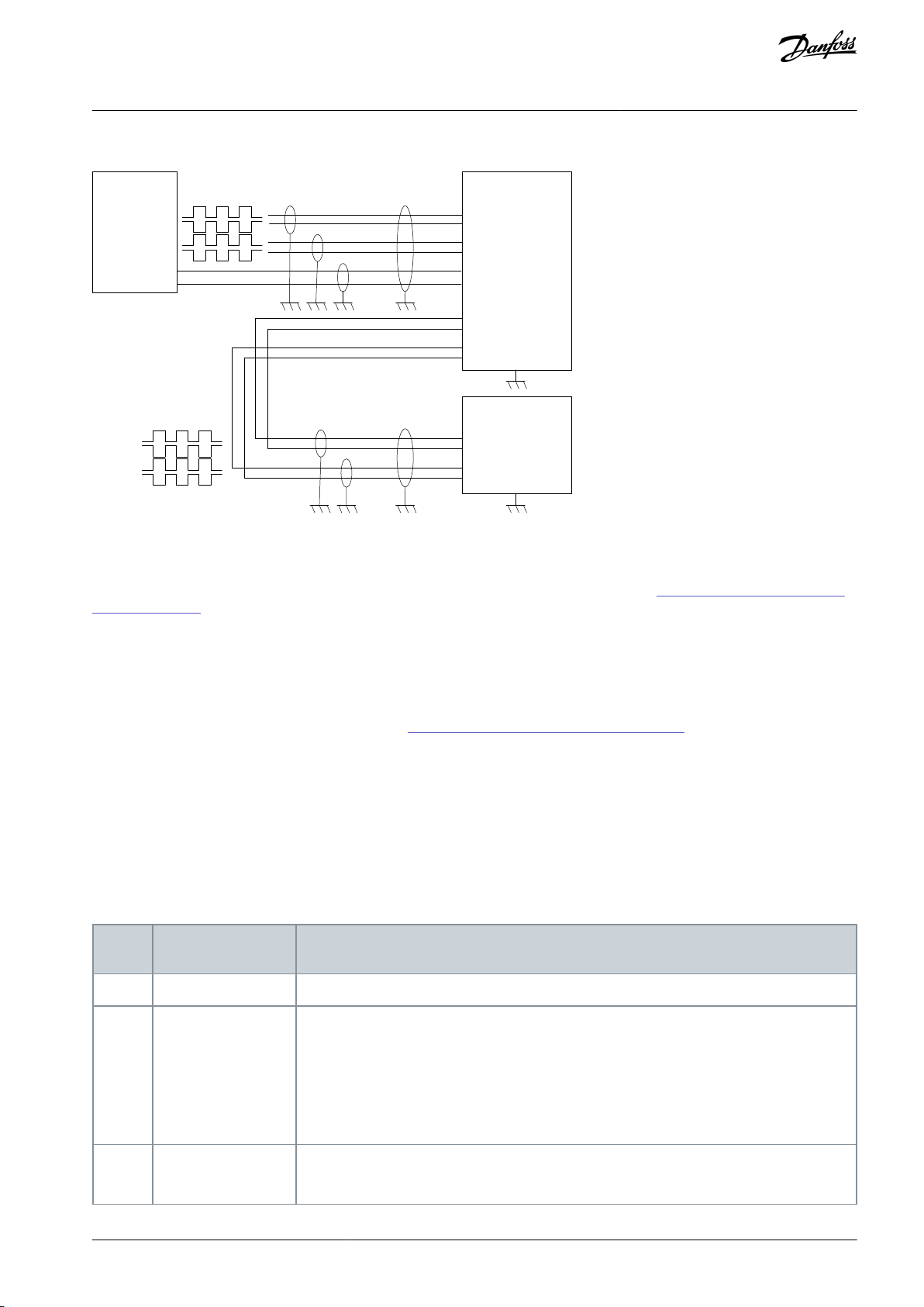
GND
A-
B-
15/24 V
Encoder Control unit 1
Channel 1
Channel 2
A+
B+
A-
B-
A+
B+
1: A1+
2: A1-
3: B1+
4: B1-
7: a+
8: a-
9: b+
10: b-
9: GND
10: Vcc
Control unit 2
Channel 1
1: A1+
2: A1-
3: B1+
4: B1-
e30bi922.10
Terminal
Signal
Technical Information
1
Reference output
+10 V, 0%...+3%, maximum current: 10 mA
2
Analog input, voltage, or current
Analog input channel 1
0...+10 V (Ri = 200 kΩ)
4–20 mA (Ri =250 Ω)
Resolution 0.1%, accuracy ±1%
Selection V/mA with DIP switches (see chapter Selection of terminal functions with DIP
switches in the Operating Guide).
3
Analog input common (current)
Differential input if not connected to ground
Allows ±20 V common-mode voltage to GND
VACON® 3000 Enclosed Drive
Operating Guide
Chain Connection
Illustration 62: Chain Connection with Duplicated Differential Inputs
Control Connections
7.10 Battery for the Real-Time Clock (RTC)
To use the real-time clock (RTC), a battery must be installed in the left side of the control unit. See 7.2 The Control Compartment of
the Enclosed Drive. Use a ½ AA battery with 3.6 V and a capacity of 1000–1200 mAh. Use, for example, a Vitzrocell SB-AA02 battery.
The battery lasts approximately 10 years. See more about the functions of the RTC in the application guides.
7.11 Galvanic Isolation Barriers
The control connections are isolated from the mains. The ground terminals are permanently connected to the I/O ground.
The digital inputs on the standard I/O board can be galvanically isolated from the I/O ground. To isolate the digital inputs, use the
DIP switch that has the positions FLOAT and GND. See 7.5.2 Isolation of the Digital Inputs from Ground.
7.12 System and Application Software
The VACON® 3000 control unit comes with AFE or INU system and application software. There is also separate application software
for the brake chopper control unit.
The application software is specific to the VACON® 3000 and comes installed on the drive. For more information, see the VACON®
3000 Application guides.
7.13 Technical Data on Control Connections
Table 21: The Standard I/O Board
AQ286660579921en-000101 / DPD02033 | 73Danfoss A/S © 2021.09

Terminal
Signal
Technical Information
4
Analog input, voltage, or current
Analog input channel 2
Default: 4–20 mA (Ri =250 Ω)
0...+10 V (Ri = 200 kΩ)
Resolution 0.1%, accuracy ±1%
Selection V/mA with DIP switches (see chapter Selection of terminal functions with DIP
switches in the Operating Guide).
5
Analog input common (current)
Differential input if not connected to ground
Allows ±20 V common-mode voltage to GND
6
24 V auxiliary voltage
+24 V, ±10%, maximum voltage ripple < 100 mV rms
Maximum 250 mA
Short-circuit protected
7
I/O ground
Ground for reference and controls (connected internally to frame ground through 1 MΩ)
8
Digital input 1
Positive or negative logic
Ri = min. 5 kΩ
0–5 V = 0
15–30 V = 1
9
Digital input 2
10
Digital input 3
11
Common A for DIN1DIN6
Digital inputs can be disconnected from ground. See chapter Isolation of digital inputs from
ground in the Operating Guide.
12
24 V auxiliary voltage
+24 V, ±10%, maximum voltage ripple < 100 mV rms
Maximum 250 mA
Short-circuit protected
13
I/O ground
Ground for reference and controls (connected internally to frame ground through 1 MΩ)
14
Digital input 4
Positive or negative logic
Ri = min. 5 kΩ
0–5 V = 0
15–30 V = 1
15
Digital input 5
16
Digital input 6
17
Common A for DIN1DIN6
Digital inputs can be disconnected from ground. See chapter Isolation of digital inputs from
ground in the Operating Guide.
18
Analog signal (+output)
Analog output channel 1, selection 0 -20 mA, load <500 Ω
Default: 0–20 mA
0–10 V
Resolution 0.1%, accuracy ±2%
Selection V/mA with DIP switches (see chapter Selection of terminal functions with DIP
switches in the Operating Guide)
Short-circuit protected
19
Analog output common
30
24 V auxiliary input
voltage
Can be used as external power back-up for the control unit
A
RS485
Differential receiver/transmitter
Set bus termination with DIP switches (see chapter Selection of terminal functions with DIP
switches in the Operating Guide). Termination resistance = 220 Ω
B
RS485
VACON® 3000 Enclosed Drive
Operating Guide
Control Connections
AQ286660579921en-000101 / DPD0203374 | Danfoss A/S © 2021.09

•
•
•
•
•
•
•
•
•
•
•
•
Terminal
Signal
Technical information
21
Relay output 1
(1)
Change-over switch (SPDT) relay. 5.5 mm isolation between channels.
Switching capacity
24 V DC / 8 A
250 V AC / 8 A
125 V DC / 0.4 A
Minimum switching load
5 V / 10 mA
222324
Relay output 2
(1)
Change-over switch (SPDT) relay. 5.5 mm isolation between channels.
Switching capacity
24 V DC / 8 A
250 V AC / 8 A
125 V DC / 0.4 A
Minimum switching load
5 V / 10 mA
252632
Relay output 3
(1)
Normally-open (NO or SPST) switch relay. 5.5 mm isolation between channels.
Switching capacity
24 V DC / 8 A
250 V AC / 8 A
125 V DC / 0.4 A
Minimum switching load
5 V / 10 mA
33
VACON® 3000 Enclosed Drive
Operating Guide
Table 22: The Standard Relay Board (+SBF3)
Control Connections
1
If 230 V AC is used as control voltage from the output relays, the control circuitry must be powered with a separate isolation transformer to limit
the short-circuit current and the overvoltage spikes. This is to prevent welding on the relay switches. Refer to standard EN 60204-1, section 7.2.9.
7.14 Auxiliary I/O Board
7.14.1 Connector Locations
AQ286660579921en-000101 / DPD02033 | 75Danfoss A/S © 2021.09
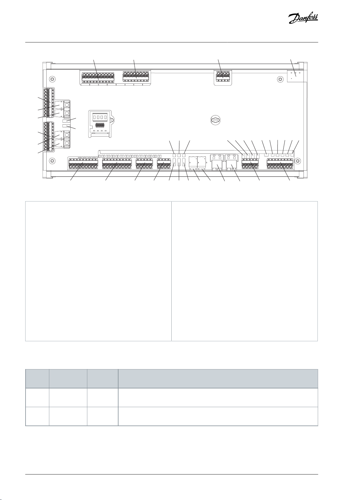
H12J14 J15 H40 H60J12 J13
J9
S1
S6
S15 S10 S9 S13 S5 S2 S18 S4 S3 S8 S7
S16
S17
S12
S11
S14
J8
H161
H160
H24
H23
J11 J10 J2 X5
J4 J3H13
e30bi609.10
H12
Breaker enable fiber optic input 2
H13
Breaker enable fiber optic input 1
H23
External breaker enable fiber optic TX2
H24
External breaker enable fiber optic RX2
H40
Communication channel 1 (PBHS)
H60
Communication channel 2 (PBHS)
H160
External breaker enable fiber optic TX1
H161
External breaker enable fiber optic RX1
J2
Grid voltage measurement, 3 channels
J3
Grid current measurement, 3 channels
J4
Analog voltage (0–10 V)/analog current (4–20 mA)
measurement, 4 channels
J8
Digital inputs (24 V, 0.5 A), 8 channels
J9
Digital inputs (24 V, 0.5 A), 8 channels
J10
Relay outputs, 4 channels
J11
Relay outputs, 5 channels
J12
Digital inputs (24 V, 0.5 A), 8 channels
J13
Digital inputs (24 V, 0.5 A), 8 channels
J14
Breaker enable digital inputs, 4 channels
J15
24 V pull-up for sensors
S1–S18
Control switches
X5
24 V input
Connector
Signal Name
Input Disable Switch
Description
H12
Breaker enable 2
S12
When light is present, the breaker is enabled. Switch in position (1-2) disables the input.
H13
Breaker enable 1
S11
When light is present, the breaker is enabled. Switch in position (1-2) disables the input.
VACON® 3000 Enclosed Drive
Operating Guide
Illustration 63: The Connectors and Switches on the Auxiliary I/O Board
Control Connections
7.14.2 Connector Specifications
Table 23: Connectors H12/H13, Breaker Enable Optical Fiber Signals
AQ286660579921en-000101 / DPD0203376 | Danfoss A/S © 2021.09

Connector
Signal
Name
Input
Disable
Switch
Description
H23
Ext Brk TX
2
–
Transmit breaker enable signal to other boards.
H24
Ext Brk RX
2
S1
Receive breaker enable signal from other boards. Switch position (1-2) disables external signal.
H160
Ext Brk TX
1
–
Transmit breaker enable signal to other boards.
H161
Ext Brk RX
1
S6
Receive breaker enable signal from other boards. Switch position (1-2) disables external signal.
Connector
Signal Name
Description
J2-1
Phase A
120/127 V phase A grid voltage input (LN peak -170 V)
J2-2
Phase B
120/127 V phase B grid voltage input (LN peak -170 V)
J2-3
Phase C
120/127 V phase C grid voltage input (LN peak -170 V)
J2-4
Reference
Neutral/return/artificial neutral
Connector
Signal Name
Switch Control
Description
J3-1
CT Supply
–
+16 V, positive supply output for hall effect sensor
J3-2
CT Supply
–
-16 V, negative supply output for hall effect sensor
J3-3
Analog Input 5 +
S2
S2 switch position (1-2) grounds Input 1P
J3-4
Analog Input 5 -
S18
S18 switch position (1-2) connects burden resistor
J3-5
Analog Input 6 +
S4
S4 switch position (1-2) grounds Input 2P
J3-6
Analog Input 6 -
S3
S3 switch position (1-2) connects burden resistor
J3-7
Analog Input 7 +
S8
S8 switch position (1-2) grounds Input 3P
J3-8
Analog Input 7 -
S7
S7 switch position (1-2) connects burden resistor
Connector
Signal Name
Switch
Control
Description
J4-1
Analog Input 1
S10
Voltage/current input 1 (single ended). Switch toggles between current and voltage.
J4-2
Analog Input 2
S9
Voltage/current input 2 (single ended). Switch toggles between current and voltage.
J4-3
Analog Input 3
S13
Voltage/current input 3 (single ended). Switch toggles between current and voltage.
J4-4
Analog Input 4
S5
Voltage/current input 4 (single ended). Switch toggles between current and voltage.
J4-5
Common
–
Return for analog voltage signals.
VACON® 3000 Enclosed Drive
Operating Guide
Table 24: Connectors H23/H24 and H160/H161, External Breaker Enable Optical Fiber Inputs/Outputs
Table 25: Connector J2, Grid Voltage (120/127 V) Measurement (Copper Wire) Analog Signals
Control Connections
Table 26: Connector J3, Grid Current Measurement (Copper Wire) Analog Signals
Table 27: Connector J4, General Purpose Voltage/Current Measurement (Copper Wire) Analog Signals
AQ286660579921en-000101 / DPD02033 | 77Danfoss A/S © 2021.09

Connector
Signal Name
Description
J8-1
Digital input 1
24 V, 0.5 A optically isolated digital input (signal bank A)
J8-2
Digital input 2
24 V, 0.5 A optically isolated digital input (signal bank A)
J8-3
Digital input 3
24 V, 0.5 A optically isolated digital input (signal bank A)
J8-4
Digital input 4
24 V, 0.5 A optically isolated digital input (signal bank A)
J8-5
Digital input 5
24 V, 0.5 A optically isolated digital input (signal bank A)
J8-6
Digital input 6
24 V, 0.5 A optically isolated digital input (signal bank A)
J8-7
Digital input 7
24 V, 0.5 A optically isolated digital input (signal bank A)
J8-8
Digital input 8
24 V, 0.5 A optically isolated digital input (signal bank A)
J8-9
Common A
Signal return for bank A
Connector
Signal Name
Description
J9-1
Digital input 9
24 V, 0.5 A optically isolated digital input (signal bank B)
J9-2
Digital input 10
24 V, 0.5 A optically isolated digital input (signal bank B)
J9-3
Digital input 11
24 V, 0.5 A optically isolated digital input (signal bank B)
J9-4
Digital input 12
24 V, 0.5 A optically isolated digital input (signal bank B)
J9-5
Digital input 13
24 V, 0.5 A optically isolated digital input (signal bank B)
J9-6
Digital input 14
24 V, 0.5 A optically isolated digital input (signal bank B)
J9-7
Digital input 15
24 V, 0.5 A optically isolated digital input (signal bank B)
J9-8
Digital input 16
24 V, 0.5 A optically isolated digital input (signal bank B)
J9-9
Common B
Signal return for bank B
Connector
Signal Name
Description
J10-1
Relay output 1 CM
Relay is disabled when breaker enable network is not satisfied.
J10-2
Relay output 1 NO
Relay is disabled when breaker enable network is not satisfied.
J10-3
Relay output 2 CM
Relay is disabled when breaker enable network is not satisfied.
J10-4
Relay output 2 NO
Relay is disabled when breaker enable network is not satisfied.
J10-5
Relay output 3 CM
Relay is disabled when breaker enable network is not satisfied.
J10-6
Relay output 3 NO
Relay is disabled when breaker enable network is not satisfied.
J10-7
Relay output 4 CM
Relay is disabled when breaker enable network is not satisfied.
J10-8
Relay output 4 NO
Relay is disabled when breaker enable network is not satisfied.
VACON® 3000 Enclosed Drive
Operating Guide
Table 28: Connector J8, 24 V/0.5 A Digital Input (Copper Wire) Signals
Table 29: Connector J9, 24 V/0.5 A Digital Input (Copper Wire) Signals
Control Connections
Table 30: Connector J10, Relay Outputs
AQ286660579921en-000101 / DPD0203378 | Danfoss A/S © 2021.09

Connector
Signal Name
Description
J11-1
Relay output 5 CM
Relay is disabled when breaker enable network is not satisfied.
J11-2
Relay output 5 NO
Relay is disabled when breaker enable network is not satisfied.
J11-3
Relay output 6 CM
Relay is disabled when breaker enable network is not satisfied.
J11-4
Relay output 6 NO
Relay is disabled when breaker enable network is not satisfied.
J11-5
Relay output 7 CM
Relay is disabled when breaker enable network is not satisfied.
J11-6
Relay output 7 NO
Relay is disabled when breaker enable network is not satisfied.
J11-7
Relay output 8 CM
Relay is disabled when breaker enable network is not satisfied.
J11-8
Relay output 8 NO
Relay is disabled when breaker enable network is not satisfied.
J11-9
Relay output 9 CM
Relay is disabled when breaker enable network is not satisfied.
J11-10
Relay output 9 NO
Relay is disabled when breaker enable network is not satisfied.
Connector
Signal Name
Description
J12-1
Digital input 17
24 V, 0.5 A optically isolated digital input (signal bank C)
J12-2
Digital input 18
24 V, 0.5 A optically isolated digital input (signal bank C)
J12-3
Digital input 19
24 V, 0.5 A optically isolated digital input (signal bank C)
J12-4
Digital input 20
24 V, 0.5 A optically isolated digital input (signal bank C)
J12-5
Digital input 21
24 V, 0.5 A optically isolated digital input (signal bank C)
J12-6
Digital input 22
24 V, 0.5 A optically isolated digital input (signal bank C)
J12-7
Digital input 23
24 V, 0.5 A optically isolated digital input (signal bank C)
J12-8
Digital input 24
24 V, 0.5 A optically isolated digital input (signal bank C)
J12-9
Common C
Signal return for bank C
Connector
Signal Name
Description
J13-1
Digital input 25
24 V, 0.5 A optically isolated digital input (signal bank D)
J13-2
Digital input 26
24 V, 0.5 A optically isolated digital input (signal bank D)
J13-3
Digital input 27
24 V, 0.5 A optically isolated digital input (signal bank D)
J13-4
Digital input 28
24 V, 0.5 A optically isolated digital input (signal bank D)
J13-5
Digital input 29
24 V, 0.5 A optically isolated digital input (signal bank D)
J13-6
Digital input 30
24 V, 0.5 A optically isolated digital input (signal bank D)
VACON® 3000 Enclosed Drive
Operating Guide
Table 31: Connector J11, Relay Outputs
Table 32: Connector J12, 24 V/0.5 A Digital Input (Copper Wire) Signals
Control Connections
Table 33: Connector J13, 24 V/0.5 A Digital Input (Copper Wire) Signals
AQ286660579921en-000101 / DPD02033 | 79Danfoss A/S © 2021.09

Connector
Signal Name
Description
J13-7
Digital input 31
24 V, 0.5 A optically isolated digital input (signal bank D)
J13-8
Digital input 32
24 V, 0.5 A optically isolated digital input (signal bank D)
J13-9
Common D
Signal return for bank D
Connector
Signal Name
Input Disable
Switch
Description
J14-1
Breaker enable
3
S14
When the signal is high, the breaker is enabled. Switch position (1-2) disables the input.
J14-2
Breaker enable
4
S15
When the signal is high, the breaker is enabled. Switch position (1-2) disables the input.
J14-3
Breaker disable 1
S16
When the signal is high, the breaker is disabled. Switch position (1-2) disables the input.
J14-4
Breaker disable 2
S17
When the signal is high, the breaker is disabled. Switch position (1-2) disables the input.
J14-5
Return
–
Return for breaker enable signals
Connector
Signal Name
Description
J15-1
24V
Current limited 24 V pull-up voltage (2 mA)
J15-2
24V
Current limited 24 V pull-up voltage (2 mA)
J15-3
GND
Return for current limited 24 V
J15-4
GND
Return for current limited 24 V
Connector
Signal Name
Description
X5-1
24V
24 V positive supply voltage
X5-2
GND
Ground (return for 24 V supply voltage)
X5-3PEProtective earth
VACON® 3000 Enclosed Drive
Operating Guide
Table 34: Connector J14, Breaker Enable, Copper Wire Signals (FK-MCP 1.5/5-ST-3.81)
Control Connections
Table 35: Connector J15, 24 V Pull-up
Table 36: Connector X5, Power Supply
7.14.3 LED Display on the Auxiliary I/O Board
There is a four character LED display on the auxiliary I/O board. The display functions in the same principle as the display on the
phase modules, but the shown belt and module information is different. See 6.7.7 LED Display on the Phase Module.
Belt information: The belt information indicator tells the number of the channel on the control unit to which the auxiliary I/O board
is connected, in this case C5 (see 7.8 Optical Fiber Connections).
The belt information indicator is of type: [ ] [ ] [C] [5].
•
The first two digits are empty.
•
The last two digits show the number of the channel.
Module information: The module information indicator tells the identification number of the auxiliary I/O board. The number of the
first installed board is 14, the second is 15, and so on.
The module information indicator is of type: [PowerID N_] [PowerID _N] [ ] [ ].
AQ286660579921en-000101 / DPD0203380 | Danfoss A/S © 2021.09

VACON® 3000 Enclosed Drive
Operating Guide
••The first two digits show the ID of the auxiliary I/O board.
The last two digits are empty.
Control Connections
AQ286660579921en-000101 / DPD02033 | 81Danfoss A/S © 2021.09

VACON® 3000 Enclosed Drive
Operating Guide
Commissioning
8 Commissioning
8.1 Safety Checks before Starting the Commissioning
Before starting the commissioning, read these warnings.
D A N G E R
SHOCK HAZARD FROM POWER UNIT COMPONENTS
The power unit components are live when the drive is connected to mains. A contact with this voltage can lead to death or seri-
ous injury.
Do not touch the components of the power unit when the drive is connected to mains. Before connecting the drive to mains,
-
make sure that the covers of the drive are closed.
D A N G E R
SHOCK HAZARD FROM TERMINALS
The motor terminals U, V, W, the brake resistor terminals, or the DC terminals are live when the drive is connected to mains, also
when the motor does not operate. A contact with this voltage can lead to death or serious injury.
Do not touch the motor terminals U, V, W, the brake resistor terminals, or the DC terminals when the drive is connected to
-
mains. Before connecting the drive to mains, make sure that the covers of the drive are closed.
D A N G E R
SHOCK HAZARD FROM DC LINK OR EXTERNAL SOURCE
The terminal connections and the components of the drive can be live several minutes after the drive is disconnected from the
mains and the motor has stopped. The load side of the drive can also generate voltage. A contact with this voltage can lead to
death or serious injury.
Disconnect the drive from the mains and make sure that the motor has stopped.
-
Disconnect the motor.
Lock out and tag out the power source to the drive.
Make sure that no external source generates unintended voltage during work.
To ground the drive input and DC link, close the grounding switch. If there is no grounding switch, make sure that the drive
input and DC link are grounded for work. Also ground the motor terminals for work.
Wait for the DC-link capacitors to discharge fully before opening the cabinet door or the cover of the AC drive. The discharge
time is <7 minutes for AFE drives and <21 minutes for 12-pulse drives.
Use a measuring device to make sure that there is no voltage.
8.2 Operating the Grounding Switch
D A N G E R
SHOCK HAZARD FROM THE DC LINK
A contact with the DC-link voltage can lead to death or serious injury.
After the AC drive is disconnected from the mains, wait for the DC link to discharge.
-
Use a measuring device to make sure that there is no voltage.
1.
Turn off the AFE and INU and disconnect the AC drive from the mains (DC link begins to discharge).
2.
Lock out/tag out the MV power source.
3.
Wait for the DC link to discharge below 50 V DC.
The discharge time is:
•
<7 minutes for AFE drives.
•
<21 minutes for 12-pulse drives.
If more DC capacitance than normal is installed, the discharge time can be longer.
AQ286660579921en-000101 / DPD0203382 | Danfoss A/S © 2021.09
Customer
Country
Project number
Location
Start date (mm/dd/yy)
Customer ID
End date (mm/dd/yy)
Drive serial number
Company personnel
Drive type code
End customer
Application
Motor Nominal Voltage (V AC)
Motor Nominal Frequency (Hz)
Motor Nominal Speed (RPM)
Motor Nominal Current (A AC)
Motor Power Factor (0–1)
Motor Nominal Power (kW)
Transformer Specifications (MVA, Secondary V RMS, %Z)
VACON® 3000 Enclosed Drive
Operating Guide
4.
Measure and make sure that the DC link is discharged before unlocking the grounding switch.
5.
Unlock the grounding switch.
There is a safety solenoid on the grounding switch. The solenoid makes sure that the switch does not close while the DC
link is energized or if the mains power is on.
6.
Close the grounding switch.
7.
Open the power module cabinet.
8.
Make sure that the DC-link voltage indication lights on the front of the phase modules are not on.
See 6.7.7 LED Display on the Phase Module.
9.
Make sure that all the blades of the grounding switch are correctly closed.
8.3 Commissioning the Drive
Before starting the commissioning, read the warnings and safety instructions in this manual.
•
Fill in the basic information about the job and the motor nameplate data.
•
Go through each item in the commissioning checklists.
-
Before power-up.
-
Control and auxiliary power commissioning.
-
Medium-voltage power commissioning.
•
Write down any findings or measured values in the comment fields.
•
Once each task is completed, mark the completion date and the name of the responsible employee.
Commissioning
8.3.1 Basic Job Information
Table 37: Basic Job Information
Table 38: Motor Nameplate Data
AQ286660579921en-000101 / DPD02033 | 83Danfoss A/S © 2021.09

•
•
•
•
•
Item
Comments
Date completed
(mm/dd/yy)
Employee
Confirm that the ambient conditions are within the specification.
See 11.2.6 Cooling.
Perform system lockout/tagout and grounding of the drive
according to specific customer installation procedure.
Make sure that the mains and motor cables are selected according to the requirements.
See 6.2 Mains and Motor Cable Selection.
Make sure that the MV input/supply cables are connected
according to the system schematic and are properly torqued.
Make sure that the output/motor cables are connected according to the system schematic and are properly torqued.
Confirm that a wire check of the MV input and output cables has been completed.
Confirm the proper grounding of the MV cable shields, motor, transformer, and drive cabinet.
See 6.4 Grounding.
Per local electrical codes, verify that the MV drive cabinet is
grounded to the earth ground of the facility.
Confirm that the drive cabinet ground busbars are connected in all sections.
See 6.4 Grounding.
Check the resistances of the grounding connections. Measure both polarities.
Resistances to check:
Control system grounding
System safety grounding
Cabinet support
External housing of the cooling fans
Door locks/handles
The resistances should be approximately ≤0.5 Ω.
Confirm that the MV input and output cables have been insulation tested according to local regulations.
Confirm that there are no power factor correction capacitors connected to the motor cable.
Check that the optical fiber cables are in good condition
and the routing is done in a way, that does not damage the
cables. For example, make sure that the maximum bending
radius of the cables (25 mm/1 in) is not exceeded.
VACON® 3000 Enclosed Drive
Operating Guide
8.3.2 Before Power-up Checklist
Table 39: Checklist of Commissioning Tasks to Do Before Power-up
Commissioning
AQ286660579921en-000101 / DPD0203384 | Danfoss A/S © 2021.09

•
•
•
•
•••
•
Item
Comments
Date completed
(mm/dd/yy)
Employee
AFE drive systems
Make sure that the phase modules (INU/AFE) are installed
correctly:
Cabling/busbars are properly torqued.
Fiber optic wires are connected in correct order.
24 V DC plug is connected.
12-pulse drive systems
Make sure that the phase modules (INU) and DFE module
are installed correctly:
Cabling/busbars properly are torqued.
Fiber optic wires are connected in correct order.
24 V DC plug is connected.
12-pulse drive systems
Make sure that the DC-link capacitors for DFE are installed
correctly:
Cabling/busbars are properly torqued.
Overpressure switch is connected to control.
Confirm that there is a minimum of 76 mm (3.0 in) from an
exposed MV terminal to ground.
Confirm that there is a minimum of 34 mm (1.35 in) from
an exposed MV terminal to opposite polarity.
Check that the main circuit wiring has correct clearance to
ground and no insulated MV cabling (SIWO-KUL) is in contact with opposite phases or the drive enclosure.
Verify that the INU/AFE phase modules and DFE power
module are connected to the correct corresponding input/
output busbar terminals (U -> U, L1 -> L1, and so on).
See 6.7 Cabling of the Power Modules.
Check that all cooling hoses are connected from the manifold to the phase modules, DFE module, and inductor heat
exchangers.
See 5.4.4.2 Cooling System Overview.
Make sure that the MV drive cooling system has been filled
and pressurized with no leaks.
See the specifications in 11.2.6 Cooling.
See the instructions in 8.4.1 Filling the Liquid Cooling Sys-
tem.
If applicable, make sure that all cooling valves are opened.
Make sure that the single-phase control power cables
(120/240 V) are connected according to the system schematic in a separate conduit from the MV cabling.
VACON® 3000 Enclosed Drive
Operating Guide
Commissioning
AQ286660579921en-000101 / DPD02033 | 85Danfoss A/S © 2021.09

Item
Comments
Date completed
(mm/dd/yy)
Employee
Make sure that the auxiliary (400–480 V AC) power cables
are connected according to the system schematic in a separate conduit from the MV cabling.
Torque all control and auxiliary input power cables after
they are connected.
See 7.4 Control Unit Cabling and 6.8.1 Low-Voltage Power
Supply Connections.
Confirm that the pre-charge voltage selection board that is
installed matches the supplied auxiliary voltage level.
See 6.8.3 Location of the Precharge Unit.
Connect the required customer communication cables and
I/O including main breaker control to the MV drive.
See the customer drive schematic and 2.5 Main Circuit
Breaker.
AFE drive systems
Verify the proper setup of grid voltage feedback.
See 8.4.2 Grid Voltage Feedback Configuration.
AFE drive systems
Verify that the PT and TVS fuses are in working condition.
Confirm that the customer cooling connection is made to
the drive cabinet heat exchanger.
See 5.4.4.3 Cooling Connections to the Enclosed Drive.
Make sure that the temperature of the liquid in the secondary circuit is at least 5°C below the temperature level in
the primary cooling circuit of the MV drive. The absolute
maximum for the secondary circuit liquid temperature is
38°C.
See 5.4.3.4 Temperature of the Cooling Liquid.
Make sure that the flow rate of the customer cooling is
greater than or equal to the required flow of the MV Drive.
See 11.2.6 Cooling.
Confirm that the unit is clean and free from any foreign objects (such as nuts, washers, bolts, tools, metal shavings).
Confirm that there is no condensation inside the drive.
See 5.4.3.5 Condensation.
VACON® 3000 Enclosed Drive
Operating Guide
Commissioning
AQ286660579921en-000101 / DPD0203386 | Danfoss A/S © 2021.09

•
•
•
•
Item
Comments
Date completed
(mm/dd/yy)
Employee
Remove the control and auxiliary power lockout/tagout so
that these LV supplies can be energized.
Apply 120/240 V single-phase control power.
Verify that the voltages are within specification.
Record the measurement.
Control voltage:
________ V AC
Apply 400–480 V AC three-phase power.
Verify that the voltages are within specification.
Record the measurement.
Auxiliary voltage:
________ V AC
Verify that the INU/AFE (if applicable), and HX control units
are powered on and communicating.
If required, install software to the AFE/INU/BCU control
units.
See 8.4.3 Installing Software on the Control Unit.
Record the software revision details.
System software revision:
______________
Application:
______________
Verify that all the power module LED displays show the
correct phase and belt information.
See 8.4.4 Verifying the Phase Module Connections.
Correct the fiber optic cable sequence if necessary.
Operate the cooling system manually.
If needed, purge air from the system.
Check for leaks.
Check the liquid temperature.
Check the flow rate.
See the cooling specification details in 11.2.6 Cooling.
Flow rate:
__________ l/min
Static pressure:
__________ bar (psi)
Test the customer I/O signals.
Verify that the external customer interlocks operate as in-
tended.
Make sure that the digital input ground is connected to the
digital system ground when floating, or to the control terminal ground.
See 7.5.2 Isolation of the Digital Inputs from Ground.
Perform the commissioning test.
See 8.4.5 Commissioning Test.
VACON® 3000 Enclosed Drive
Operating Guide
8.3.3 Control and Auxiliary Power Commissioning Checklist
Table 40: Checklist of Control and Auxiliary Power Commissioning Tasks
Commissioning
AQ286660579921en-000101 / DPD02033 | 87Danfoss A/S © 2021.09

Item
Comments
Date completed
(mm/dd/yy)
Employee
Remove the main power lockout/tagout, so that the main
power can be applied.
AFE drive systems
Perform the AFE synchronization test and tuning. See 8.4.6
AFE Synchronization Test.
12-pulse drive systems
Issue the start command to the drive, therefore energizing
the DC link through the 12-pulse input.
Verify the charging of the DC link to the rated level in an
acceptable time (below the value programmed for the DClink timeout: ≤60 s)
Pre-charge time:
________ s
Discharge time:
________ s
Confirm that the INU control unit is giving the "Online and
ready" signal.
Check that the motor parameters have been set in the INU
control unit.
Perform the Motor ID Run (P3.1.2.8.1) with or without rotation.
For details, see the VACON® 3000 Application Guide.
If applicable, make sure that the encoder is connected and
configured properly.
See 8.4.7 Encoder Setup.
To verify correct rotation, operate the motor (with the load
uncoupled).
Operate the motor (with the load uncoupled) and incrementally increase the output up to the maximum rated frequency.
Operate the motor under load.
Verify the operation up to full load.
Tune the control parameters as necessary to achieve the
required operational specifications of the application.
VACON® 3000 Enclosed Drive
Operating Guide
8.3.4 Medium-Voltage Power Commissioning Checklist
Table 41: Checklist of Medium-Voltage Power Commissioning Tasks
Commissioning
8.4 Commissioning Procedures
8.4.1 Filling the Liquid Cooling System
Before operating a drive, the cooling system must be filled, pressurized, and purged of air. For this procedure, it is assumed that the
system is empty of cooling liquid and must be filled. Under normal situations, the system has already been tested before shipping
out and typically has some fluid.
Note:
AQ286660579921en-000101 / DPD0203388 | Danfoss A/S © 2021.09
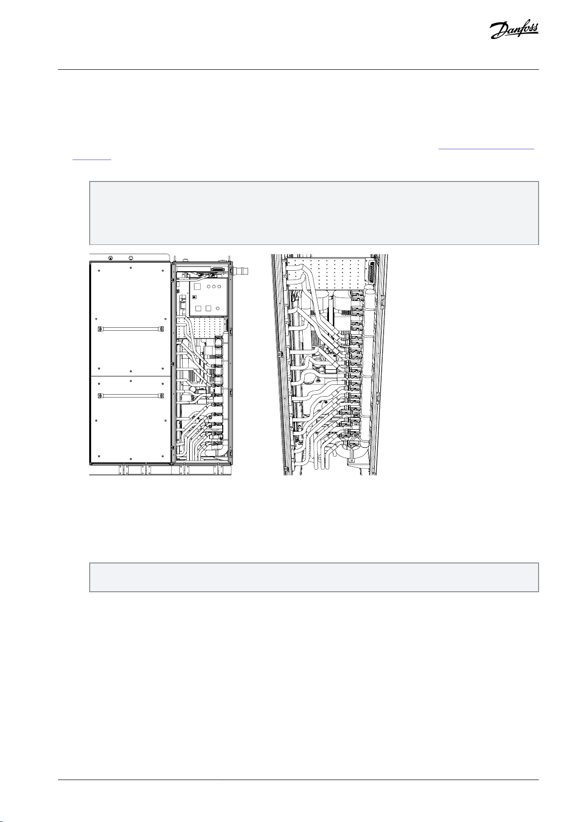
e30bi799.10
VACON® 3000 Enclosed Drive
Operating Guide
•
Accessibility to certain components of the cooling system can be an issue depending on the layout of the drive and/or the heat
Commissioning
exchanger unit.
•
This guide is not intended to be used as a reference for commissioning cooling systems which are not installed in a VACON®
3000 enclosed drive.
•
Operation and maintenance instructions for Adwatec heat exchangers are available for download at Danfoss product materials
– Adwatec.
1.
To access the inlet and outlet cooling manifolds, locate the cabinet in which the cooling system is installed.
The location of the manifolds varies depending on the internal layout of the cabinet. Sometimes there might not be access to install quick disconnects to the manifolds. In these cases, it is necessary to connect straight to one of the hoses on
the power module instead of the manifold.
In the example illustration, the inlet and outlet manifolds are easily accessible. The inlet hoses on the manifold are marked
with blue tape and the outlet hoses with red tape.
Illustration 64: Cooling Liquid Inlet and Outlet Manifolds
2.
Connect the cooling fluid pump assembly to the inlet and outlet manifolds with quick connects (if available). Open the
valves.
3.
Before filling the system with glycol, verify that all cooling hoses throughout the system are firmly connected and/or torqued. Make certain that any hoses with valves connected to a module have their valves in the open position.
4.
Make sure that the automatic air purger on the main heat exchanger is uncapped and its valve is open.
The air purger is on the main heat exchanger, behind the HX control cabinet. Its location varies depending on the cabinet
and heat exchanger design.
AQ286660579921en-000101 / DPD02033 | 89Danfoss A/S © 2021.09

e30bi800.10
e30bi801.10
VACON® 3000 Enclosed Drive
Operating Guide
Illustration 65: Air Purger Location
5.
Begin running the standalone pump and fill the system. Water should be flowing into the inlet while a combination of water and air pockets/bubbles are flowing out from the outlet. If any leak is detected, immediately shut off the pump.
The power of the pump and size of the cooling system dictates the flow rate and how quickly the air can be purged from
the system. Use an appropriately sized pump. A pump of at least 0.5 hp or greater is ideal.
Commissioning
6.
When air bubbles/pockets flowing out of the outlet hose are no longer visible, stop the pump.
7.
Close the inlet and outlet valves.
8.
Slowly open the air bleeders on the pumps. Air bubbles out. When the bubbling starts becoming only fluid seeping out,
close off the bolts to seal the pumps.
The air bleeders are in the front of the pump, just below the motor. There is one on each of the motor pumps.
Illustration 66: Air Bleeders on the Pumps
9.
Open the inlet and outlet valves and start to run the standalone pump from the glycol tank again.
a.
Run the pump for at least 5 minutes before shutting off.
b.
Close the inlet and outlet valves.
c.
Repeat step 8. There should be fewer air bubbles this time around.
d.
Move to step 10.
10.
Pressurize the system.
a.
Open the inlet valve.
b.
Activate the standalone glycol pump.
AQ286660579921en-000101 / DPD0203390 | Danfoss A/S © 2021.09

AUTO 0 SERVICE
MAIN SWITCH
RUN FAULT ALARM
RESET
P1
1
1
2 3
2
0
P2 P1+P2
e30bi802.10
e30bi803.10
VACON® 3000 Enclosed Drive
Operating Guide
c.
Wait for the pressure to build up to approximately 1.2 bar.
d.
Close the inlet valve and turn off the pump.
11.
Run the heat exchanger.
a.
Verify that the HX is in ready state (blinking green light).
b.
There are two knobs on the HX control panel. Set the right knob to P1+P2 and the left knob to Service.
c.
The drive of the HX starts to run one of the pumps.
d.
Run the pump for about 5 minutes and stop by turning the left knob back to 0 position.
The HX cooling system requires 480 V AC to run.
Commissioning
Illustration 67: Heat Exchanger Control Panel
12.
Wait ~2 minutes after stopping. Briefly open and close the outlet valve. More air bubbles should come out. Repeat this
several times until the pressure is no longer enough to force out any more air pockets.
Illustration 68: Removing the Air
13.
Run the standalone pump again.
a.
Open the inlet valve.
b.
Start to operate the standalone pump and open the outlet valve.
AQ286660579921en-000101 / DPD02033 | 91Danfoss A/S © 2021.09
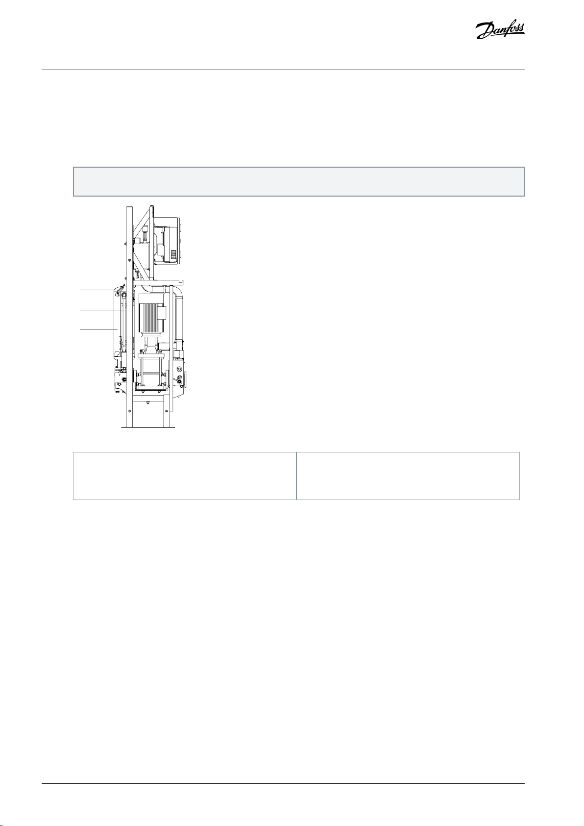
B
A
C
e30bi804.10
A
Air filling tank
B
Fluid level gauge
C
Nozzle
VACON® 3000 Enclosed Drive
Operating Guide
c.
d.
e.
14.
When the air has been purged, pressurize the system to 1.2 bar with the standalone pump again.
15.
Check the fluid level gauge.
There is a tank labeled “Air Filling” to the rear of the cooling system cabinet. The fluid level gauge is connected to this
tank. On this gauge, is a marker labeled “nominal level”.
Commissioning
Repeat steps 10–12.
After the 2nd cycle, the number of air pockets that are purged should be reduced.
Repeat the cycle until there are only few small air bubbles remaining. It is not possible to eliminate all the air bub-
bles.
Illustration 69: Location of the Fluid Level Gauge
-
If the fluid level is above the nominal line: To release excess fluid back into the glycol tank, open the outlet valve. The
pressure drops from the 1.2 bar. If the fluid level is still above the “nominal” line after the pressure drops to 0, add air to
the “air filling” tank until the fluid level drops to the “nominal” marker.
-
If the fluid level is below the nominal line: Bleed air out of the tank by pressing the pin on the nozzle. The fluid level on
the gauge climbs while the pressure decreases from 1.2 bar. Operate the standalone pump and repressurize. The goal is
to be at or slightly above the nominal marker while having 1.2 bar of pressure.
8.4.2 Grid Voltage Feedback Configuration
Grid voltage feedback is a critical component of AFE drives. It must be correctly connected and configured for an AFE drive to be
able to properly synchronize with the MV input supply voltage of the drive.
Grid voltage feedback is also necessary to perform the commissioning test. For the commissioning test to be done safely, it must be
able to detect whether there is mains power applied to the drive (that it is not powered).
AQ286660579921en-000101 / DPD0203392 | Danfoss A/S © 2021.09

e30bi770.10
VACON® 3000 Enclosed Drive
Operating Guide
1.
Locate the grid voltage feedback connector on the AFE control unit. It is located next to the FO1–FO6 fiber optic slots.
Illustration 70: Grid Voltage Feedback Connector on the AFE Control Unit
2.
Identify the type of potential transformer that is connected from the MV supply to the drive. The feedback configuration is
either Wye or Delta.
3.
Connect the grid voltage feedback to the AFE control unit based on the PT type.
-
If the PT is WYE configured:
Connect phase A to CH1.
Connect phase B to CH2.
Connect phase C to CH3.
Connect the reference to CHR.
Go to the 2.1.1 Line Configuration menu and do these parameter settings:
Grid Voltage FBK Ch A: AN phase voltage
Grid Voltage FBK Ch B: BN phase voltage
Grid Voltage FBK Ch C: CN phase voltage
-
If the PT is Delta configured:
Connect phase A to CH1.
Connect phase B to CHR.
Connect phase C to CH3.
Leave CH2 empty.
Go to the 3.1.1 Line Configuration menu and do these parameter settings:
Grid Voltage FBK Ch A: AB line voltage
Grid Voltage FBK Ch B: Ground/reference
Grid Voltage FBK Ch C: CB line voltage
4.
Set the other parameters in the 3.1.1 Line Configuration menu.
Nominal Grid Voltage/Frequency: Set to the rated input voltage/frequency of the drive.
a.
Grid Voltage FBK Mode: Set to "Source Voltage".
b.
Grid Voltage FBK Scale: Set based on the expected voltage on the PT secondary. For example, a 35:1 PT ratio at
c.
4160 V equals ≈ 118.8 V secondary voltage.
Filter Topology: Set to "LCL".
d.
Regen Filter Select: Select based on the type of phase modules used in the drive.
e.
Commissioning
For example, L20.4, where L20 is the phase module size (L20 or L30) and 4 stands for the input voltage (3=3300 V
and 4=4160 V).
AQ286660579921en-000101 / DPD02033 | 93Danfoss A/S © 2021.09

e30bi772.10
VACON® 3000 Enclosed Drive
Operating Guide
f.
Special Filter Index: Set to 21000.
Commissioning
8.4.3 Installing Software on the Control Unit
To install the software, each control unit must be connected to separately. After finishing one software installation, disconnect the
cable and move it to the next control unit. Make sure that the correct control unit (AFE/INU/BCU) is connected to the PC.
Items required for the software installation:
•
RS485 to USB cable.
•
PC or laptop.
•
The VACON® Live PC tool.
Download VACON® Live from .
Verify that the control unit is powered (the screen on the control panel is on).
1.
Verify that the indicator light on the control unit is green (there are no faults).
2.
If the indicator light is green, skip to step #3.
-
If the indicator light is red, check the number of the fault. If the fault code is 59 (communication fault), one or more of
the power modules is likely disconnected.
Before opening the cover of the power module section to check the connections, verify that medium voltage is
locked out.
Check the modules and verify that the fiber optic cables and the 24 V DC supply are properly connected.
Verify that all the indicator lights are lit on each of the modules.
When the communication fault is cleared, continue to the next step.
If there are still issues with the fault, refer to *INU and AFE phasing* procedure for troubleshooting.
To access the RS485 port, remove the control panel from the control unit.
3.
Connect the RS485 end of the cable to the port on the control unit and the USB end to a PC.
4.
5.
Open the VACON® Live PC tool. When prompted for startup mode, select Online.
6.
After VACON® Live completes searching for connected drives, select the drive, and click Connect to Selected.
Illustration 71: Connecting to the Drive with VACON® Live
7.
After VACON® Live opens, save the current parameter settings.
a.
Open the File menu and select Save file as….
b.
Select an appropriate file name (for example, customer name_drive identity_date).
c.
Save the file into a folder/location that coincides with the contents of the file.
8.
Obtain an up-to-date software build directly from the Danfoss server or request one from the Danfoss software team.
The software build is a file with a ".vcx" extension.
9.
Click this file, and VACON® Loader opens automatically. If VACON® Live is still open, you are prompted to close it.
10.
Click Next to begin.
11.
The same procedure as in VACON® Live for connecting to the drive occurs (step 6). After searching for connected drives is
completed, select the drive, and click Connect to Selected.
AQ286660579921en-000101 / DPD0203394 | Danfoss A/S © 2021.09

e30bi773.10
VACON® 3000 Enclosed Drive
Operating Guide
Commissioning
12.-Select the appropriate modules to be installed. The modules selected vary depending on the control unit and the drive
type.
Illustration 72: Selecting the Modules to Install in VACON® Loader
Modules to install for AFE control unit in AFE drive
Control firmware
Control firmware (part2)
Select appropriate language
AFE AVUS1253AFE application
M-star firmware
Network configuration
Filter parameters
Belt 1 A phase firmware
Belt 1 B phase firmware
Belt 1 C phase firmware
If the AFE drive has a parallel module configuration, also select the following modules:
Belt 2 A phase firmware
Belt 2 B phase firmware
AQ286660579921en-000101 / DPD02033 | 95Danfoss A/S © 2021.09

VACON® 3000 Enclosed Drive
Operating Guide
Belt 2 C phase firmware
If the AFE drive has an Auxiliary I/O board, select the following modules:
Channel 4 Index 1 AUX firmware
No position 2 firmware
No position 3 firmware
If the AFE drive has no Auxiliary I/O board, select the following modules:
No position 1 firmware
No position 2 firmware
No position 3 firmware
-
Modules to install for INU control unit in AFE drive
Control firmware
Control firmware (part2)
Select appropriate language
INU AVUS1252INU application
M-star firmware
Network configuration
Filter parameters
Belt 1 A phase firmware
Belt 1 B phase firmware
Belt 1 C phase firmware
If the drive has a parallel module configuration, select the following modules:
Belt 2 A phase firmware
Belt 2 B phase firmware
Belt 2 C phase firmware
For the INU control unit of an AFE drive, there are no Auxiliary I/O board settings since the Auxiliary I/O board is already
connected to the AFE control unit. Select the modules:
No position 1 firmware
No position 2 firmware
No position 3 firmware
-
Modules to install for INU control unit in 12-pulse drive
Control firmware
Control firmware (part2)
Select appropriate language
INU AVUS1252INU application
M-star firmware
Network configuration
Filter parameters
Belt 1 A phase firmware
Belt 1 B phase firmware
Belt 1 C phase firmware
If the drive has a parallel module configuration, select the following modules:
Belt 2 A phase firmware
Belt 2 B phase firmware
Belt 2 C phase firmware
If the 12-pulse drive has an Auxiliary I/O board, select the following modules:
Commissioning
AQ286660579921en-000101 / DPD0203396 | Danfoss A/S © 2021.09

VACON® 3000 Enclosed Drive
Operating Guide
Channel 4 Index 1 AUX firmware
No position 2 firmware
No position 3 firmware
Also select the following modules:
Channel 4 Index 1 CBL firmware
No position 2 firmware
No position 3 firmware
-
Modules to install for CBU control unit in 12-pulse drive (optional)
Control firmware
Control firmware (part2)
Select appropriate language
BCU AVUS1260BCU application
Single unit network configuration
Belt 1 A phase firmware
13.
When the appropriate modules are selected, click Next to begin the installation.
The loading time takes upwards of 30 minutes to complete depending on how many modules are loaded.
Commissioning
14.
After the loading is completed, click Yes to close VACON® Loader.
If the loading fails to reach 100% completion and stops, try again starting from step 8. Before attempting to reinstall:
15.
Check that the core board is fully seated on the auxiliary I/O board.
a.
Check that the fiber cable from the auxiliary I/O board to the appropriate control unit is connected in the correct
b.
ports at both ends.
After the software loading is completed, perform a parameter compare between the new parameter set and the parameter
16.
settings saved in step 7.
See the instructions for comparing the parameters in the VACON® 3000 Application Guides.
8.4.4 Verifying the Phase Module Connections
Before running the drive for the first time, verify the phasing of the INU and/or AFE modules. The verification is done both physically
(cabling, busbars) and electrically (identified with 24 V DC control power and fiber optic communication cables).
Obtain a copy of the mechanical drawings of the drive and identify the locations of the phase modules.
1.
Perform a continuity check of the phase module terminal connections.
2.
For INU modules, check the continuity of the connections from the output on the phase module to its correspond-
a.
ing output busbar terminal.
For AFE modules, check the continuity of the connections from the output to the L1, L2, L3 busbars where the
b.
main input supply voltage cables are mounted.
For dual-belt drives, do the same for the other belt.
c.
Verify, that the fiber optic cables are connected properly between the control units and phase modules.
3.
The fiber from the FO1 slot on the control unit connects to the fiber connector A on either the INU U-phase module or the
AFE L1-phase module. The control unit automatically designates the phase module connected to FO1 as a U-phase module (if INU control unit) or L1-phase module (if AFE control unit).
See
7.8 Optical Fiber Connections.
4.
For the remaining module-to-module connections, connect the optical fiber from connector B of the U-phase module to
connector A of the next module (which is then designated as V-phase). Then connect the optical fiber from connector B of
the V-phase module to connector A of the next module (W-phase). Leave connector B of the last module (W-phase) empty.
The AFE connections are the same, except the designations for the modules are L1, L2, and L3.
5.
If the connections are correct and control power is applied, then the phase modules show the correct belt and phase information on the 4-character LED displays.
In the operation mode, the LED display view changes at an interval of 3 s. The display changes between the belt information indicator and the module information indicator. See 6.7.7 LED Display on the Phase Module.
AQ286660579921en-000101 / DPD02033 | 97Danfoss A/S © 2021.09

VACON® 3000 Enclosed Drive
Operating Guide
-
INU, belt 1
Module 1: __B1 and _2_U
Module 2: __B1 and _3_V
Module 3: __B1 and _4_W
INU, belt 2 (if applicable)
Module 4: __B2 and _5_U
Module 5: __B2 and _6_V
Module 6: __B2 and _7_W
-
AFE, belt 1
Module 1: __B1 and _2L1
Module 2: __B1 and _3L2
Module 3: __B1 and _4L3
AFE, belt 2 (if applicable)
Module 4: __B2 and _5L1
Module 5: __B2 and _6L2
Module 6: __B2 and _7L3
6.
Confirm that the identification on the LED displays matches the correct input or output terminal that the phase module is
connected to.
Commissioning
8.4.5 Commissioning Test
The commissioning test verifies that the drive can be successfully operated without applying medium voltage to the main power
terminals (L1, L2, L3). The purpose of the test is to verify operation of the system interlocks and that the pre-charge circuit can close
the contactor that supplies medium voltage to the drive.
•
This test does not power up the drive.
•
This test does not run if:
-
Medium voltage is detected on the input to the mains contactor.
-
The pre-charge unit has 480 V AC supply power and is connected to the circuit.
•
If either of these two conditions is present, the control unit generates a fault.
The following procedures must be completed before performing the commissioning test:
•
INU/AFE module installation.
•
INU/AFE phasing (see 8.4.4 Verifying the Phase Module Connections).
•
Software download (see 8.4.3 Installing Software on the Control Unit).
•
Cooling fluid addition (see 8.4.1 Filling the Liquid Cooling System).
•
Insulation test of the MV input and output cables.
•
Grid voltage feedback configuration (see 8.4.2 Grid Voltage Feedback Configuration).
Remove power from the input to the main supply power contactor or main circuit breaker (MCB).
The drive controls switchgear external to the drive to supply utility voltage to the drive. There is no main circuit breaker internal to
the drive that opens/closes the voltage on the supply terminals (L1, L2, L3). The lockout/tagout procedure must be properly performed.
1.
To prevent accidental charging of the DC link, open the circuit breaker that supplies 480 V AC to the pre-charge unit.
The circuit breaker is in the control compartment. See the wiring diagrams delivered with the drive.
2.
Verify that there was no mistake in the control power wiring and that there is no shock hazard.
a.
On the INU phase modules, disconnect the 24 V DC connector.
See 6.7.1 Phase Module L20/L30 Terminals.
b.
Use a DMM in V AC mode and measure from the +24 V and 0 V terminals to GND.
AQ286660579921en-000101 / DPD0203398 | Danfoss A/S © 2021.09

BYPASS
ON
S1
FR1
FR2
LED
e30bi775.10
VACON® 3000 Enclosed Drive
Operating Guide
3.
Verify that the "breaker enable" DIP switches are in the correct position.
The DIP switches (S1) are on the INU/AFE control unit between fiber optic connectors FR1 and FR2. These two fiber optic
inputs are used for the "breaker enable" function. If the DIP switches are in the correct position, a green LED next to the
switches is on.
Commissioning
Illustration 73: "Breaker Enable" Connectors, DIP Switches, and LED
-
If the "breaker enable" function is not used, the fiber optic connectors are plugged. Check that both DIP switches are in
the "bypass" position.
-
If one or both of the "breaker enable" inputs are used, then the corresponding DIP switches must be in the "on" position.
4.
In VACON® Live, make sure that “PCC Gating Enabled” is checkmarked in the Precharge Status Word. If the breaker enable
is not properly set, then the commissioning test fails due to failure to receive MX close feedback.
Location of PreCharge Status Word in the menu:
INU application: V2.12.4
•
AFE application: V2.10.4
•
5.
Set the Commissioning test mode parameter to Enable.
Parameter location in the menu:
AFE drives: P3.3.5.3
•
12-pulse drives (INU application): P3.17.5.3
•
The commissioning test can then be performed with the HMI touch screen or with the VACON® Live PC tool.
6.
Commissioning test with the HMI touch screen, see
-
-
Commissioning test with the VACON® Live PC tool, see 8.4.5.2 Commissioning Test with VACON® Live.
8.4.5.1 Commissioning Test with HMI Touch Screen.
8.4.5.1 Commissioning Test with HMI Touch Screen
1.
Select the Start Cond tab on the HMI, and check that all the interlocks are made. The power-up sequence starts only if all
boxes are highlighted in green.
If a condition is not met, the box is solid black and it must be addresses before the test can be performed.
2.
Give the system a Power On command.
The location of the Power On command in the menu varies depending on the type of drive (12-pulse or AFE).
3.
Check that the cooling system starts. The drive of the heat exchanger runs and the HX circulates the cooling liquid.
4.
Check the PLC Status. It should show Charging, but the DC-link voltage should not charge (should be 0 V DC).
AQ286660579921en-000101 / DPD02033 | 99Danfoss A/S © 2021.09

VACON® 3000 Enclosed Drive
Operating Guide
5.
Check that the main contactor closes after the DC pre-charge timeout has elapsed.
The location of the DC Precharge Timeout parameter:
•
AFE application: P3.3.4.9
•
INU application (12-pulse): P3.17.4.9
6.
After the mains contact has been closed, give the system a Power Off command.
7.
Set the Commissioning Test Mode parameter to Disabled.
8.4.5.2 Commissioning Test with VACON® Live
1.
In VACON® Live, go to the Precharge monitoring menu. To see if the drive is ready to attempt a commissioning test, check
the monitoring values Precharge State and PowerOn State.
AFE application:
•
Precharge monitoring menu: M2.10
•
Precharge State monitoring value: V2.10.1
•
PowerOn State monitoring value: V2.10.5.1
INU application (12-pulse):
•
Precharge monitoring menu: M2.12
•
Precharge State monitoring value: V2.12.1
•
PowerOn State monitoring value: V2.12.5.1
Commissioning
If either of the two values is not in "ready" state, then an interlock is active and must be resolved before the com-
missioning test can be attempted. Determine what is missing (which unchecked box must be checked), and check
the hardware and/or I/O settings of the device which is failing to give the required feedback.
2.
Right-click the PowerOn State parameter, select To Monitoring, and then New Monitor. This value is then used to determine
whether the commissioning test is completed successfully.
If Precharge State and PowerOn State are both "ready", then PowerOn State has a value of "3" when viewed with
the monitoring function.
Give the system a "power on" command.
3.
a.
Go to the Internal Control menu.
b.
Change the value of parameter Power Off to "DigIN Slot0.2".
c.
Change the value of parameter Power On to "DigIN Slot0.2".
AFE application:
•
Internal Control menu: M3.3.2.2
•
Power Off parameter: P3.3.2.2.2
•
Power On parameter: P3.3.2.2.1
INU application (12-pulse):
•
Internal Control menu: M3.17.2.2
•
Power Off parameter: P3.17.2.2.2
•
Power On parameter: P3.17.2.2.1
Check that the cooling system starts.
4.
Check that the drive of the heat exchanger runs and the HX circulates the cooling liquid.
a.
b.
Check that the PowerOn State changes to "4" when the HX starts.
5.
Keep monitoring PowerOn State. After a while, the system starts to pre-charge the DC link. In reality, there is no voltage
being generated in the DC link. The value set in parameter DC Precharge Timeout starts to count down. PowerOn State
shows a value of "5" during the countdown.
The location of the DC Precharge Timeout parameter:
AQ286660579921en-000101 / DPD02033100 | Danfoss A/S © 2021.09
 Loading...