

Page 1

vacon®20 x
ac drives
BH application manual
Page 2

Page 3

vacon • 0
INDEX
Document ID: DPD01381A
Rev. A
Version release date: 11.10.13
Corresponds to application package ACIT1124V101.vcx
1. BH Application .................................................................................................2
1.1 Specific functions of Vacon BH application ...................................................................... 2
1.2 ASi Board Diagnostic........................................................................................................3
1.3 Description of the terminals (D-option with AS-interface) .............................................. 4
1.3.1 MU2 connections............................................................................................................... 4
1.3.2 MU3 connections............................................................................................................... 6
1.4 Description of the terminals (D-option with Profibus) ..................................................... 8
1.4.1 MU2 connections............................................................................................................... 8
1.4.2 MU3 connections............................................................................................................. 10
2. Description of Groups .................................................................................... 12
2.1 Monitor group: menu MON ............................................................................................. 12
2.1.1 ASi.................................................................................................................................... 12
2.1.2 Sensors............................................................................................................................ 12
2.1.3 Motor ............................................................................................................................... 12
2.1.4 Drive ................................................................................................................................ 13
2.2 Parameter Groups: Menu PAR ....................................................................................... 14
2.2.1 Group Motor settings: Menu PAR G1 .............................................................................. 15
2.2.2 Group Start/Stop Settings: Menu PAR G2....................................................................... 16
2.2.3 Group References: Menu PAR G3 ................................................................................... 17
2.2.4 Group Ramps: Menu PAR G4 .......................................................................................... 19
2.2.5 Group Input functions: Menu PAR G5 ............................................................................ 20
2.2.6 Group Output functions: Menu PAR G6........................................................................... 21
2.2.7 Group Mechanical brake: Menu PAR G7......................................................................... 22
2.2.8 Group Supervisions: Menu PAR G8................................................................................. 23
2.2.9 Group Motor Control: Menu PAR G9............................................................................... 24
2.2.10 Group Protections: Menu PAR G10................................................................................. 25
2.2.11 Group Automatic reset: Menu PAR G11.......................................................................... 27
2.2.12 Group Non-ASi fieldbus: Menu PAR G12........................................................................ 28
2.2.13 Group Analogue output: Menu Par G13.......................................................................... 29
2.2.14 Group User interface: Menu Par G14.............................................................................. 29
2.3 System parameters, Faults and History faults: Menu FLT ............................................ 30
2.4 Keypad Reference: Menu REF ........................................................................................ 32
3. Parameter description................................................................................... 34
3.1 Motor Settings ................................................................................................................. 34
3.2 Start/Stop settings ..........................................................................................................36
3.3 References ...................................................................................................................... 38
3.4 Ramps.............................................................................................................................. 40
3.5 Input functions................................................................................................................. 42
3.6 Output functions .............................................................................................................. 44
3.7 Mechanical brake ............................................................................................................ 46
3.8 Supervisions .................................................................................................................... 47
3.9 Motor control................................................................................................................... 48
3.10 Protections ...................................................................................................................... 52
3.11 Automatic reset............................................................................................................... 58
3.12 Non-ASi fieldbus ............................................................................................................. 59
3.12.1 Modbus fieldbus mapping............................................................................................... 60
3.13 Analogue Output.............................................................................................................. 62
3.14 User interface.................................................................................................................. 62
Service support: find your nearest Vacon service center at www.vacon.com
Page 4

vacon • 1
4. Fault tracing .................................................................................................. 64
Page 5

BH Application vacon • 2
1. BH APPLICATION
The VACON® 20 CP/X drive with +D option contains a preloaded application for instant use.
The parameters of this application are listed in chapter 2.2 of this manual and explained in
more detail in chapter 2.
1.1 Specific functions of Vacon BH application
The Vacon BH application allows flexible use of VACON® 20 CP/X frequency converters.
The visibility of parameters and monitors is arranged in three access levels, selected by parameter P14.1.
Code Parameter Min Max Default Description
0 = Basic
P14.1 Parameter access level 0 2 0
1 = Advanced
2 = Service
Basic:
• Monitor of ASi inputs and outputs (only with +D option and AS-interface connection)
• Monitor of sensors
• Monitor of main motor variables
• Setting of motor data
• Setting of Run control mode and commonly used speed reference
• Setting of basic ramp times
• Setting of quick stop function
• Setting of ASi inputs and outputs functions
Advanced:
• Basic + Monitor of more drive/motor variables
• More options for Start/stop and reference selection
• Setting of a second set of ramp times
• Setting of advanced motor control
• Setting of mechanical brake control
• Setting of protections and autoreset
Service:
• Advanced + Monitor of drive internal I/Os
• Setting of some extra motor control and protections features
• Setting of analogue and relay outputs
1)
1)
terminals of analogue output and relays are not accessible in standard Vacon 20 CP/X+D
drive.
Service support: find your nearest Vacon service center at www.vacon.com
1
Page 6

vacon • 3 BH Application
1.2 ASi Board Diagnostic
This information is valid only for Vacon® 20X with +D option and AS-interface connection.
Monitor V1.3 shows the state of ASi board, as numeric code.
Visual information is provided by red Fault led on the drive's cover.
Off: no anomaly
On: cumulative fault state. Reset is needed to restore operations.
Slow blinking: ASi board is not powered.
Fast blinking: ASi board is powered, but not communicating (to see V1.3).
A fault condition (code 64) is generated if communication fails while the drive is in Run state in
Automatic mode.
This fault is automatically reset when Manual mode is selected. The drive can operate in Manual mode, even though the ASi anomaly is still displayed (alarm code 64).
Run is prevented in Automatic mode, until communications is restored.
1
Page 7
BH Application vacon • 4
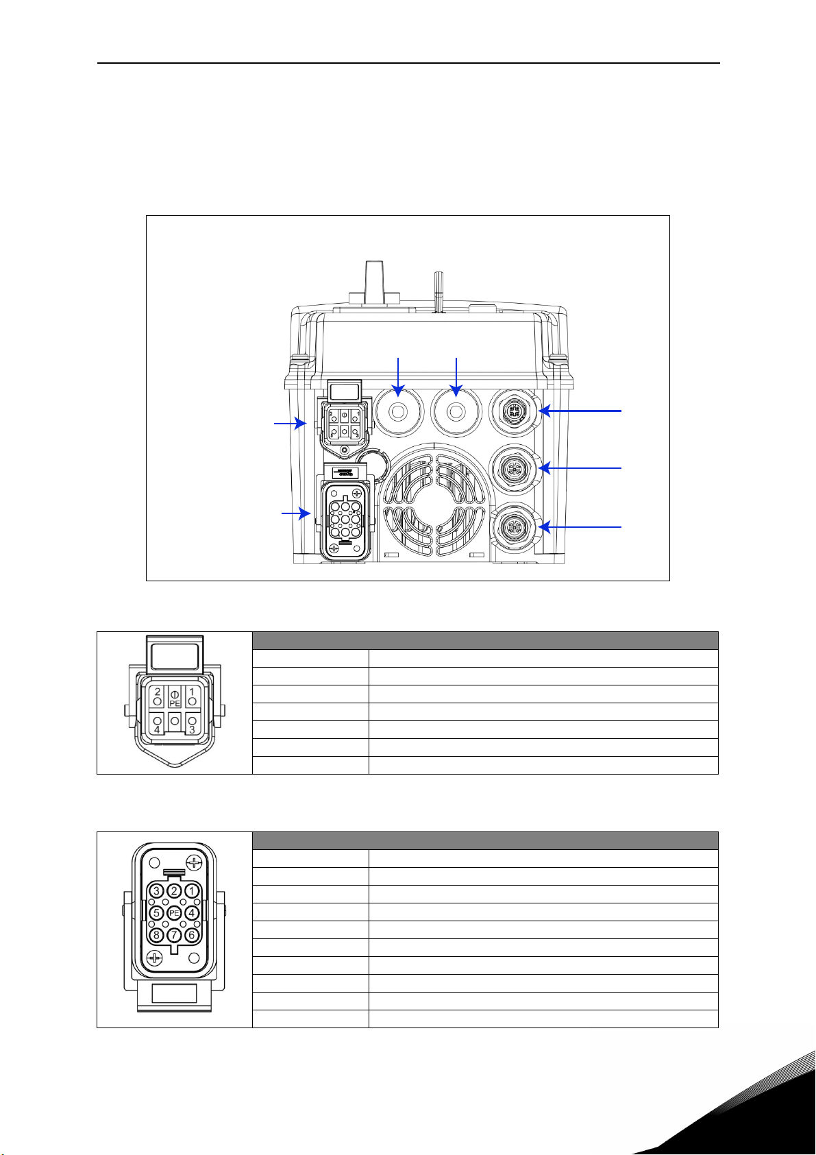
1.3 Description of the terminals (D-option with AS-interface)
The following pictures describe the power and M12 terminals in Vacon 20X drives with D-option
and AS-interface connection.
1.3.1 MU2 connections
X5 X4
Mains supply
Motor output
Figure 1. Power and control terminals in MU2.
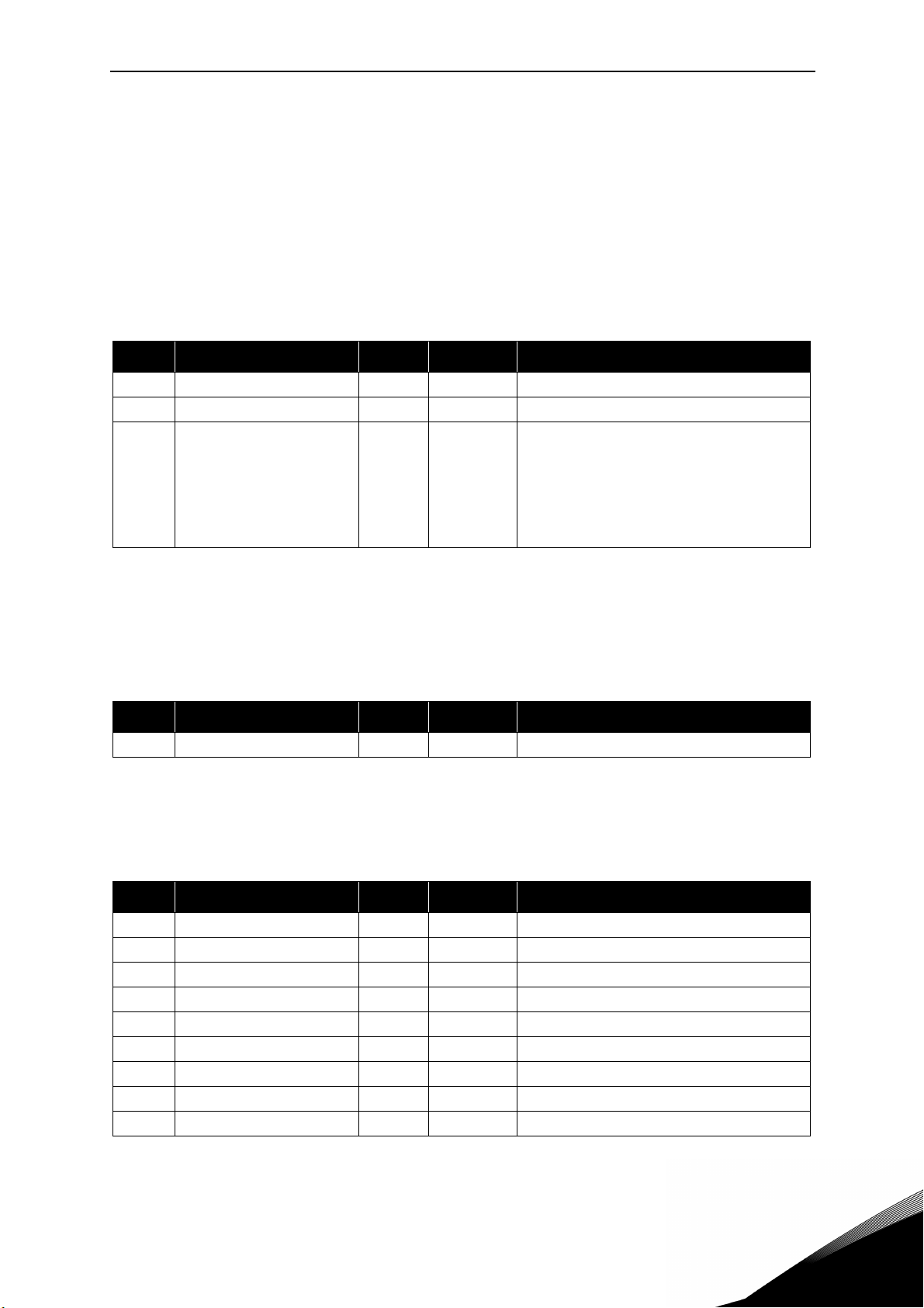
Mains supply / Type HAN Q5/0 (Male)
Pin Function
1L1
2L2
3L3
45PE Protective Earth
X3
X2
X1
Table 1. Mains supply connector, MU2.
Motor output / Type HAN Q8 (Female)
Pin Function
1U
2 Not connected
3W
4Brake (-)
5Temperature sensor (+)
6Brake (+)
7V
8Temperature sensor (-)
PE Protective Earth
Table 2. Motor supply connector, MU2
Service support: find your nearest Vacon service center at www.vacon.com
1
Page 8

vacon • 5 BH Application
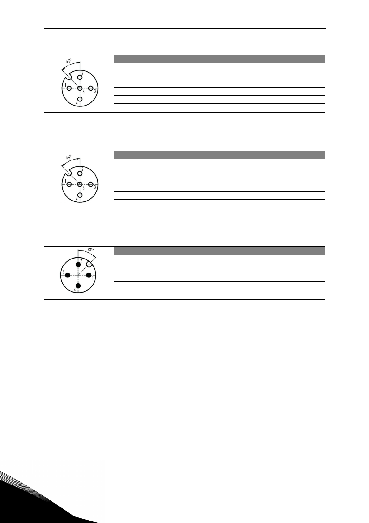
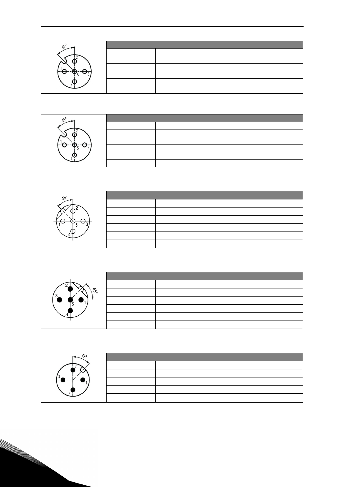
X1 Digital Input / Type M12 A-Coding – 5 pole (Female)
Pin Function
1 +24V (25mA max.)
2D input 1
3GND
4D input 2
5Functional Earth
Table 3. X1 connector, MU2.
X2 Digital Input / Type M12 A-Coding – 5 pole (Female)
Pin Function
1 +24V (25mA max.)
2D input 3
3GND
4D input 4
5Functional Earth
Table 4. X2 connector, MU2.
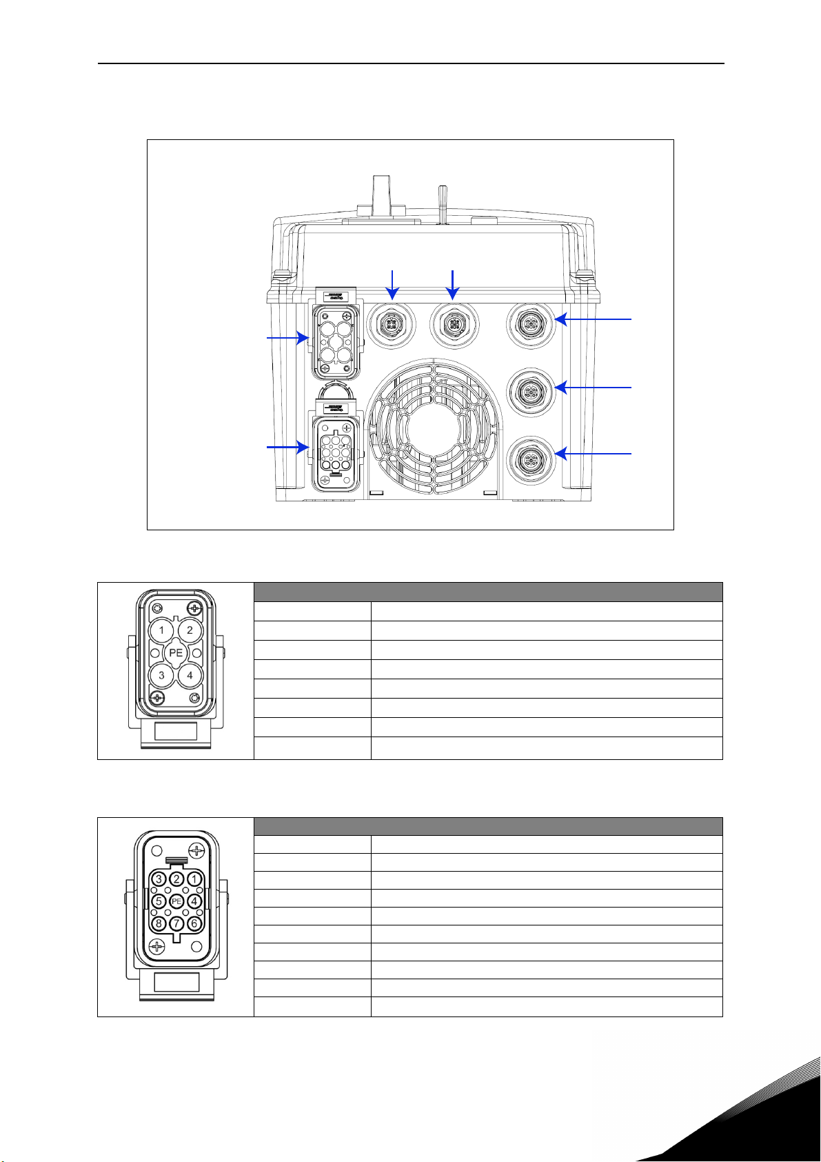
X3 ASi connections / Type M12 A-Coding – 4 pole (Male)
Pin Function
1ASi +
20V
3ASi 4 +24V
Table 5. AS-interface connector, MU2.
1
Page 9
BH Application vacon • 6
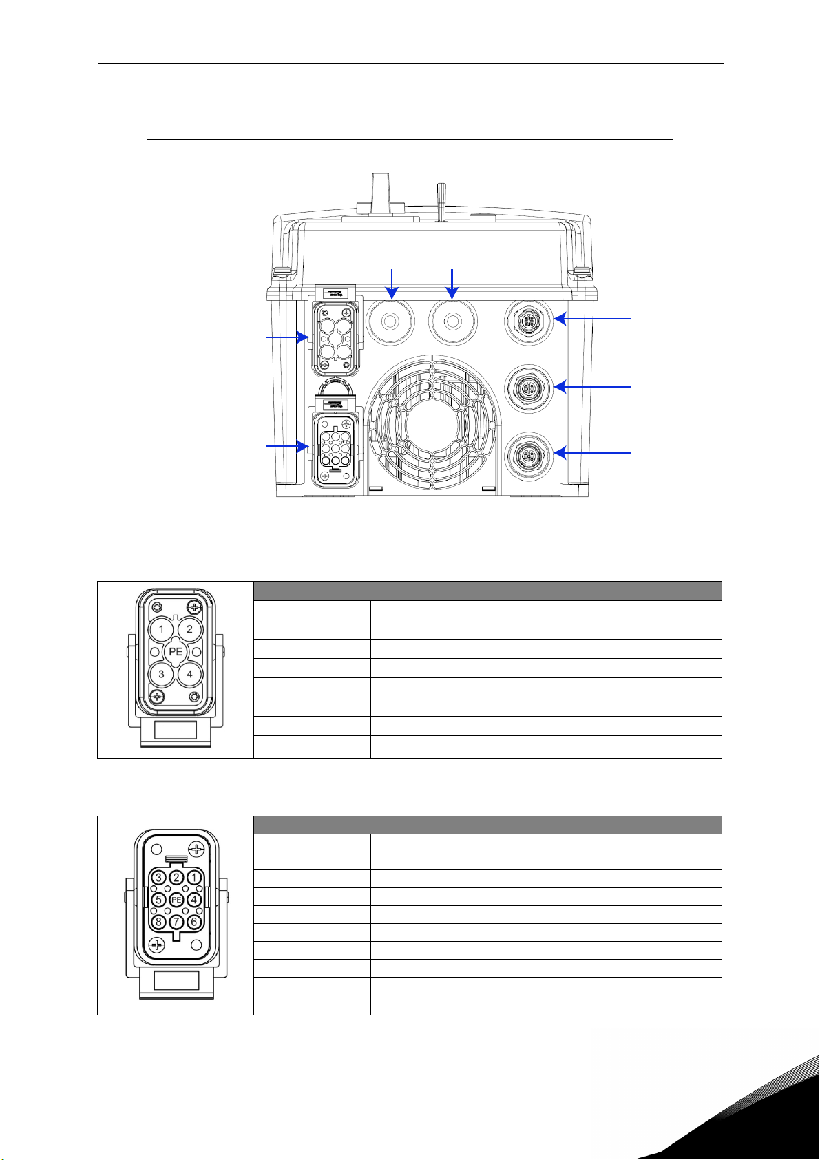
1.3.2 MU3 connections
X4X5
Mains supply
Motor output
Figure 2. Power and control terminals in MU3.
X3
X2
X1
Mains supply / Type HAN Q4/2 (Male)
Pin Function
1L1
2L2
3L3
411 12 -
PE Protective Earth
Table 6. Mains supply connector, MU3.
Motor output / Type HAN Q8 (Female)
Pin Function
1U
2 Not connected
3W
4Brake (-)
5Temperature sensor (+)
6Brake (+)
7V
8Temperature sensor (-)
PE Protective Earth
Table 7. Motor supply connector, MU3.
Service support: find your nearest Vacon service center at www.vacon.com
1
Page 10
vacon • 7 BH Application
X1 Digital Input / Type M12 A-Coding – 5 pole (Female)
Pin Function
1 +24V (25mA max.)
2D input 1
3GND
4D input 2
5Functional Earth
Table 8. X1 connector, MU3.
X2 Digital Input / Type M12 A-Coding – 5 pole (Female)
Pin Function
1 +24V (25mA max.)
2D input 3
3GND
4D input 4
5Functional Earth
Table 9. X2 connector, MU3.
X3 ASi connections / Type M12 A-Coding – 4 pole (Male)
Pin Function
1ASi +
20V
3ASi 4 +24V
Table 10. AS-interface connector, MU3.
1
Page 11
BH Application vacon • 8
t
3X2
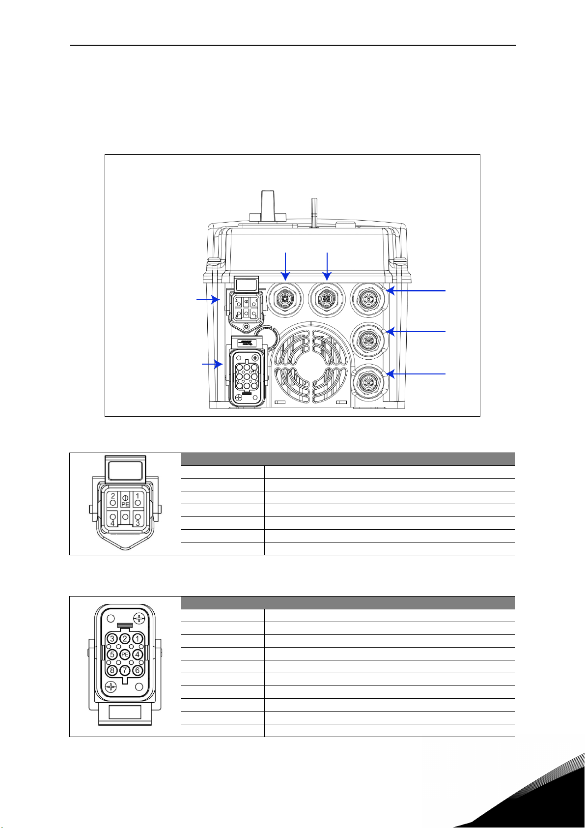
1.4 Description of the terminals (D-option with Profibus)
The following pictures describe the power and M12 terminals in Vacon 20X drives with D-option
and Profibus connection.
1.4.1 MU2 connections
X5 X4
Mains supply
Motoroutpu
Figure 3. Power and control terminals in MU2.
Mains supply / Type HAN Q5/0 (Male)
Pin Function
1L1
2L2
3L3
45PE Protective Earth
X
X1
Table 11. Mains supply connector, MU2.
Motor output / Type HAN Q8 (Female)
Pin Function
1U
2 Not connected
3W
4Brake (-)
5Temperature sensor (+)
6Brake (+)
7V
8Temperature sensor (-)
PE Protective Earth
Table 12. Motor supply connector, MU2
Service support: find your nearest Vacon service center at www.vacon.com
1
Page 12
vacon • 9 BH Application
X1 Digital Input / Type M12 A-Coding – 5 pole (Female)
Pin Function
1 +24V (25mA max.)
2D input 1
3GND
4D input 2
5Functional Earth
Table 13. X1 connector, MU2.
X2 Digital Input / Type M12 A-Coding – 5 pole (Female)
Pin Function
1 +24V (25mA max.)
2D input 3
3GND
4D input 4
5Functional Earth
Table 14. X2 connector, MU2.
X3 Profibus / Type M12 B-Coding – 5 pole (Female)
Pin Function
12 A (green)
34B (red)
5-
Table 15. Profibus Female connector, MU2.
X4 Profibus / Type M12 B-Coding – 5 pole (Male)
Pin Function
12 A (green)
34B (red)
5-
Table 16. Profibus Male connector, MU2.
X5 Auxiliary power supply / Type M12 A-Coding – 4 pole (Male)
Pin Function
1 Power supply +24V
23Power supply GND
4-
1
Table 17. Auxiliary power supply connector, MU2.
Page 13
BH Application vacon • 10
s
s
y
2X3
1.4.2 MU3 connections
X4X5
Main
uppl
Motor output
Figure 4. Power and control terminals in MU3.
X
X1
Mains supply / Type HAN Q4/2 (Male)
Pin Function
1L1
2L2
3L3
411 12 -
PE Protective Earth
Table 18. Mains supply connector, MU3.
Motor output / Type HAN Q8 (Female)
Pin Function
1U
2 Not connected
3W
4Brake (-)
5Temperature sensor (+)
6Brake (+)
7V
8Temperature sensor (-)
PE Protective Earth
Table 19. Motor supply connector, MU3.
Service support: find your nearest Vacon service center at www.vacon.com
1
Page 14

vacon • 11 BH Application
X1 Digital Input / Type M12 A-Coding – 5 pole (Female)
Pin Function
1 +24V (25mA max.)
2D input 1
3GND
4D input 2
5Functional Earth
Table 20. X1 connector, MU3.
X2 Digital Input / Type M12 A-Coding – 5 pole (Female)
Pin Function
1 +24V (25mA max.)
2D input 3
3GND
4D input 4
5Functional Earth
Table 21. X2 connector, MU3.
X3 Profibus / Type M12 B-Coding – 5 pole (Female)
Pin Function
12 A (green)
34B (red)
5-
Table 22. Profibus Female connector, MU3.
X4 Profibus / Type M12 B-Coding – 5 pole (Male)
Pin Function
12 A (green)
34B (red)
5-
Table 23. Profibus Male connector, MU3.
X5 Auxiliary power supply / Type M12 A-Coding – 4 pole (Male)
Pin Function
1 Power supply +24V
23Power supply GND
4-
1
Table 24. Auxiliary power supply connector, MU3.
Page 15
Description of Groups vacon • 12
2. DESCRIPTION OF GROUPS
2.1 Monitor group: menu MON
VACON® 20 CP/X AC drive provides you with a possibility to monitor the actual values of parameters and signals as well as statuses and measurements. Some of the values to be monitored are adjusted. See Table 25, Table 26, Table 27 and Table 28 in which the monitoring
values are presented.
2.1.1 ASi
Code Monitoring value Unit Level Description
V1.1 ASi Outputs 4, 3, 2,1 Basic State of received bits on ASi board
V1.2 ASi Inputs 4, 3, 2, 1 Basic State of transmitted bits on ASi board
0: power off
1: communication ok
V1.3 ASi board state Basic
2: no master
3: address=0
4: periphery fault
5: serious periphery fault
Table 25: ASi monitoring items.
NOTE: these values are valid only with Vacon 20 CP/X +D and AS-interface connection.
2.1.2 Sensors
Code Monitoring value Unit Level Description
V2.1 Sensors 4, 3, 2, 1 Basic State of sensors read on digital inputs
Table 26: Sensors monitoring item.
2.1.3 Motor
Code Monitoring value Unit Level Description
V3.1 Output frequency Hz Basic Output frequency to motor
V3.2 Frequency reference Hz Basic Frequency reference to motor control
V3.3 Motor speed rpm Basic Motor speed in rpm
V3.4 Motor current A Basic
V3.5 Motor torque % Advanced Calculated shaft torque
V3.6 Motor shaft power % Advanced Total power consumption of AC drive
V3.7 Motor voltage V Advanced
V3.8 Motor temperature % Advanced Calculated motor temperature
V3.9 Process variable Advanced Scaled process variable
Table 27: Motor monitoring items.
Service support: find your nearest Vacon service center at www.vacon.com
2
Page 16

vacon • 13 Description of Groups
2.1.4 Drive
Code Monitoring value Unit Level Description
V4.1 DC link voltage V Advanced
V4.2 Unit temperature °C Advanced Heatsink temperature
V4.3 Board temperature °C Service Power board temperature
V4.4
V4.5
V4.6 Analogue input 1 % Service Analogue input AI1
V4.7 Analogue input 2 % Service Analogue input AI2
V4.8 DI3, DI2, DI1 Service Digital inputs status
V4.9 DI6, DI5, DI4 Service Digital inputs status
V4.10 DO, RO2, RO1 Service Digital outputs status
V4.11 Analogue output % Service Analogue output
Actual output
frequency
Droop frequency
reference
Hz Service
Hz Service
Output frequency inclusive slip compensation
Frequency setpoint inclusive droop
correction
Table 28: Drive monitoring items.
2
Page 17

Description of Groups vacon • 14
2.2 Parameter Groups: Menu PAR
The Decentralized Application embodies the following parameter groups:
Menu and Parameter group Description
Group Motor settings: Menu PAR G1 Motor settings
Group Start/Stop Settings: Menu PAR G2 Start/Stop and mode settings
Group References: Menu PAR G3 Frequency reference selection
Group Ramps: Menu PAR G4 Ramp times
Group Input functions: Menu PAR G5 Digital input programming
Group Output functions: Menu PAR G6 ASi and digital output programming
Group Mechanical brake: Menu PAR G7 Mechanical brake programming
Group Supervisions: Menu PAR G8 Supervision programming
Group Motor Control: Menu PAR G9 Motor control and U/f parameters
Group Protections: Menu PAR G10 Protections configuration
Group Automatic reset: Menu PAR G11 Auto reset after fault configuration
Group Non-ASi fieldbus: Menu PAR G12 Non-ASi Fieldbus data out parameters
Group Analogue output: Menu Par G13 Analogue output programming
Group User interface: Menu Par G14 User interface parameters
Table 29: Parameter groups
Column explanations:
Code = Location indication on the keypad; Shows the operator the parameter num-
ber.
Parameter= Name of parameter
Min = Minimum value of parameter
Max = Maximum value of parameter
Unit = Unit of parameter value; Given if available
Default = Value preset by factory
ID = ID number of the parameter
Description= Short description of parameter values or its function
= The parameter may be changed only in Stop state
Service support: find your nearest Vacon service center at www.vacon.com
2
Page 18

vacon • 15 Description of Groups
2.2.1 Group Motor settings: Menu PAR G1
Code Parameter Min Max Unit Default Level Description
Find this value U
rating plate of the motor.
This parameter sets the
P1.1 Motor nominal voltage 120 500 V 400 Basic
P1.2
P1.3 Motor nominal speed 80 20000 rpm 1440 Basic
P1.4 Motor nominal current
P1.5 Motor Cos Phi 0.30 1.00 0.85 Basic
P1.6
P1.7 U/f optimization 0 1 1 Basic
P1.8 Motor control mode 0 1 0 Advanced
P1.9 Load drooping 0.00 20.00 % 0.00 Advanced Speed loss at 100% load
P1.10 Motor Identification 0 1 0 Basic
Motor nominal
frequency
Motor current limit
8.00 320.00 Hz 50.00 Basic
0.2 x I
0.2 x I
2 x I
H
2 x I
H
A
H
A
H
I
H
1.5 x I
Basic
Basic
H
voltage at the field weakening point to 100% * U
Note also used connection
(Delta/Star).
Find this value f
ing plate of the motor.
Find this value nn on the rating plate of the motor.
Find this value In on the rating plate of the motor.
Find this value on the rating
plate of the motor
Maximum motor current
from AC drive
0 = Not active
1 = Auto torque boost
0 = Frequency control
1 = Speed control
0 = not active
1 = standstill identification
(to activate, RUN command
within 20s)
on the
n
nMotor
on the rat-
n
.
NOTE!
Table 30: Group Motor settings.
P1.6 is automatically set equal to 150% of motor nominal current when P1.4 is
modified
2
Page 19

Description of Groups vacon • 16
2.2.2 Group Start/Stop Settings: Menu PAR G2
Code Parameter Min Max Unit Default Level Description
Logic = 0:
Start sgn 1 = Start Forward
Start sgn 2 = Start Backward
Logic =1:
Start sgn 1 = Start Forward
P2.1
P2.2
P2.3 Start function 0 1 0 Advanced
P2.4 Stop function 0 1 0 Advanced
P2.5 Quick Stop Function 0 1 0 Basic
P2.6 Manual Start mode 0 1 1 Advanced
AUTO
Start/Stop logic
AUTO
Run control
03 0 Basic
01* 1Advanced
(edge)
Start sgn 2 = Start Backward (edge)
Logic = 2:
Start sgn 1 = Start
Start sgn 2 = Reverse
Logic = 3:
Start sgn 1 = Start (edge)
Start sgn 2 = Reverse
0= Start 1-Start 2 signals
1= non-ASi fieldbus
0=Ramping
1=Flying start
0=Coasting
1=Ramping
0=Signal level
1=Signal edge
0=Signal level
1=Signal edge
NOTE!
Table 31: Group Start/Stop settings.
(*)Selection 1 is available only if ASi board is not installed. In this case a different
fieldbus can be used to control the drive. When ASi board is installed this parameter is automatically set to 0.
Service support: find your nearest Vacon service center at www.vacon.com
2
Page 20

vacon • 17 Description of Groups
2.2.3 Group References: Menu PAR G3
Code Parameter Min Max Unit Default Level Description
P3.1 Minimum frequency 0.00 P3.2 Hz 0.00 Basic
P3.2 Maximum frequency P3.1 320.00 Hz 50.00 Basic
AUTO
P3.3
P3.4 Preset frequency 0 P3.1 P3.2 Hz 50.00 Basic Multistep speed 0
P3.5 Preset frequency 1 P3.1 P3.2 Hz 10.00 Basic
P3.6 Preset frequency 2 P3.1 P3.2 Hz 15.00 Basic
P3.7 Preset frequency 3 P3.1 P3.2 Hz 20.00 Basic
P3.8 Preset frequency 4 P3.1 P3.2 Hz 25.00 Advanced
P3.9 Preset frequency 5 P3.1 P3.2 Hz 30.00 Advanced
P3.10 Preset frequency 6 P3.1 P3.2 Hz 40.00 Advanced
P3.11 Preset frequency 7 P3.1 P3.2 Hz 50.00 Advanced
P3.12
P3.13
P3.14
P3.15
P3.16
P3.17
P3.18
P3.19
P3.20 Manual Preset speed 0.00 P3.2 Hz 50.00 Basic
Frequency reference
selection
Motor potentiometer
Mode
Motor potentiometer
Step Up
Motor potentiometer
Step Down
Motor pote ntiometer in
Reverse
Motor potentiometer
Ramp time
Motor potentiometer
Copy ref.
Motor potentiometer
Reset
MANUAL
Reference selection
0
01 0Advanced
0.01 50.00 Hz 5.00 Basic
0.01 50.00 Hz 5.00 Basic
01 0Basic
150Hz/s5Advanced
01 0Advanced
02 0Basic
02
1)
2
2Basic
3)
1
Advanced
Minimum allowed frequency reference
Maximum allowed frequency reference
Selection of AUTO reference
source:
0 = Preset frequency 0
1 = Motor potentiometer
2 = Non-ASi fieldbus
Multistep speed 1
Multistep speed 2
Multistep speed 3
Multistep speed 4
Multistep speed 5
Multistep speed 6
Multistep speed 7
0: Step up/down
1: Continuous
At any edge of increase signal
At any edge of decrease signal
0: Forward
1: Reverse
Rate of change in the motor
potentiometer reference
when increased or
decreased.
In case MotPot is alternated
with Preset.
0: Keep memory of previous
MotPot Ref
1: Start from actual Ref
Motor potentiometer frequency reference reset
logic.
0 = No reset
1 = Reset if stopped or powered down
2 = Reset if powered down
Selection of MANUAL reference source:
0 = Manual Preset speed
1 = Panel potentiometer
2 = Manual Preset speed +
Panel Potentiometer Correction
2)
2)
2)
2)
2)
2)
2)
2
Table 32: Group References.
Page 21

Description of Groups vacon • 18
P3.21
P3.22
P3.23
P3.24
NOTE!
Panel Potentiometer
Min. Frequency
Panel Potentiometer
Max. Frequency
Panel Potentiometer
Min. Correction
Panel Potentiometer
Max. Correction
0.00 P3.21 Hz 0.0 Advanced
P3.20 P3.2 Hz 50.00 Advanced
-100.00 0.00 % -10.00 Advanced
0.00 100.00 % 10.00 Advanced
Minimum freq. reference
from potentiometer
Maximum freq.reference
from potentiometer
Ref adjust at minimum
potentiometer signal
Ref adjust at maximum
potentiometer signal
Table 32: Group References.
1)
Selection 2 is available only if ASi board is not installed. In this case a different
fieldbus can be used to control the reference.When ASi board is installed this
parameter is automatically set to 0.
2)
In AUTO mode, preset speed 1-8 can be directly activated by ASi outputs or
Sensors signals, independently from P3.3 setting.
If P3.3 = 1 and the reference is restored to motor potentiometer, after a preset
speed, P3.17 defines the initial value for the reference.
3)
When ASi board is installed this parameter is automatically set to 0.
Service support: find your nearest Vacon service center at www.vacon.com
2
Page 22

vacon • 19 Description of Groups
2.2.4 Group Ramps: Menu PAR G4
Code Parameter Min Max Unit Default Level Description
Defines the time required
for the output frequency to
P4.1 Acceleration time 1 0.1 3000.0 s 3.0 Basic
P4.2 Deceleration time 1 0.1 3000.0 s 3.0 Basic
P4.3 Ramp 1 shape 0.0 10.0 s 0.0 Basic Rounded speed profile.
P4.4 Acceleration time 2 0.1 3000.0 s 10.0 Advanced
P4.5 Deceleration time 2 0.1 3000.0 s 10.0 Advanced
P4.6 Ramp 2 shape 0.0 10.0 s 0.0 Advanced Rounded speed profile.
P4.7
P4.8
P4.9
Acceleration time 2
freq. threshold
Deceleration time 2
freq. threshold
Quick Stop dec.
time
0.00 P3.2 Hz 0.00 Advanced
0.00 P3.2 Hz 0.00 Advanced
0.1 3000.0 s 1.0 Basic
increase from zero frequency to maximum frequency
Defines the time required
for the output frequency to
decrease from maximum
frequency to zero frequency
Time from 0 to max frequency
Time from 0 to max frequency
Threshold for auto change
from acc1 to acc2
Threshold for auto change
from dec2 to dec1
Time from max frequency
to 0
Table 33: Group Ramps.
2
Page 23

Description of Groups vacon • 20
2.2.5 Group Input functions: Menu PAR G5
Code Parameter Min Max Unit Default Level Description
Start signal 1 when control
place is I/O 1 (FWD)
See P2.1 for function.
0 = not used
1 = ASi Output 1
P5.1 Start signal 1 0 8 1 Basic
P5.2 Start signal 2 0 8 2 Basic
P5.3
P5.4
P5.5
P5.6 Fault reset 0 4 Basic Resets all active faults
P5.7 Force brake 0 8 0 Basic Forces brake open
P5.8 External fault open 0 8 0 Advanced
P5.9 External fault close 0 8 0 Advanced
P5.10 Run enable 0 8 0 Advanced
P5.11
P5.12
P5.13
P5.14 Quick Stop open 0 8 0 Basic
P5.15 Quick Stop open 0 8 0 Basic
Preset frequency
selection 0
Preset frequency
selection 1
Preset frequency
selection 2
Acc/dec ramp
selection
Motor potentiometer
UP
Motor potentiometer
DOWN
08 3Basic
08 0Basic
08 0Advanced
08 0Advanced
08 0Basic
08 0Basic
2 = ASi Output 1
3 = ASi Output 1
4 = ASi Output 1
5 = Sensor 1
6 = Sensor 2
7 = Sensor 3
8 = Sensor 4
Start signal 2 when control
place is I/O 1 (REV).
See P2.1 for function.
See P5.1 for selections.
Binary selector for Preset
speeds (0-7).
Binary selector for Preset
speeds (0-7).
Binary selector for Preset
speeds (0-7).
Fault is signal low
See P5.1 for selections
Fault if signal high
See P5.1 for selections
Must be on to set drive in
Ready state
Activates ramp 2
See P5.1 for selections
Reference increase
See P5.1 for selections
Reference decrease
See P5.1 for selections
If configured, low signal activates stop with specific ramp.
See P5.1 for selections.
If configured, high signal
activates stop with specific
ramp.
See P5.1 for selections.
Table 34: Group Input functions.
Service support: find your nearest Vacon service center at www.vacon.com
2
Page 24

vacon • 21 Description of Groups
2.2.6 Group Output functions: Menu PAR G6
Code Parameter Min Max Unit Default Level Description
Bit0 transmitted on ASi bus
0: not used
1: Sensor 1
2: Sensor 2
3: Sensor 3
4: Sensor 4
5: Ready + Auto
6: Run
7: Fault
P6.1 ASi Input 1 0 17 5 Basic
P6.2 ASi Input 2 0 17 13 Basic
P6.3 ASi Input 3 0 17 2 Basic
P6.4 ASi Input 4 0 17 4 Basic
P6.5
P6.6
P6.7 RO1 ON delay 0.00 320.00 s 0.00 Service ON delay for relay
P6.8 RO1 OFF delay 0.00 320.00 s 0.00 Service OFF delay for relay
P6.9 RO1 inversion 0 1 0 Service
P6.10 RO2 ON delay 0.00 320.00 s 0.00 Service See P6.7
P6.11 RO2 OFF delay 0.00 320.00 s 0.00 Service See P6.8
RO1 function
RO2 function
2)
2)
013 0Service
0 13 0 Service See P6.5
8: Fault or warning
9: Reverse
10: Running feedback
11: Automatic mode
12: At speed (internal)
13: Output freq superv
14: Output current superv
15: Brake command
16: Quick stop
17: Ready
Bit1 transmitted on ASi bus.
See P6.1 for selections
Bit2 transmitted on ASi bus.
See P6.1 for selections
Bit2 transmitted on ASi bus.
See P6.1 for selections
Function selection for RO1:
0 = Not used
1 = Ready
2 = Run
3 = General fault
4 = General fault inverted
5 = Warning
6 = Reversed
7 = At speed
8 = Output freq. supervision
9 = Output current superv.
10 = ASi Output 1
11 = ASi Output 2
12 = ASi Output 3
13 = ASi Output 4
0 = no inversion
1 = inverted
1)
2
Table 35: Group Output Functions.
Page 25

Description of Groups vacon • 22
Automatic Run Out Freq >= Setpoint Feedback
0 - - 0
1 0 - 1
1 1 0 0
1 1 1 1
1)
when Automatic mode is not assigned to any Input, Running Feedback includes
also information about Automatic.
NOTE!
2)
relay terminals are not accessible in standard V20X+D drive
2.2.7 Group Mechanical brake: Menu PAR G7
Code Parameter Min Max Unit Default Level Description
P7.1
P7.2 Brake open current 0.00 100.0 % 0.0 Advanced
P7.3 Brake close frequency 0.00 10.00 Hz 1.00 Advanced
P6.4 Brake close delay 0.00 10.00 s 0.00 Advanced
Brake open frequency
1)
0.00 10.00 Hz 0.00 Advanced
Frequency threshold for brake
open
Current threshold for brake
open
Frequency threshold for brake
close (Start = 0)
Respected in any condition
(fault, no enable), apart direct
control from Asi input.
NOTE!
Table 36: Group Mechanical brake.
1)
note: if P7.1 > 0Hz, frequency reference is internally limited to P7.1 + 0.1 Hz
until the brake is released. If the thresholds in P7.1 and P7.2 are not reached
within 3s from Start command Fault 56 “Brake Time Out” is triggered.
Service support: find your nearest Vacon service center at www.vacon.com
2
Page 26

vacon • 23 Description of Groups
2.2.8 Group Supervisions: Menu PAR G8
Code Parameter Min Max Unit Default Level Description
P8.1
P8.2
P8.3
P8.4
P8.5
P8.6
P8.7
Running Ok speed
tolerance
Output frequency
supervision
Frequency supervision
limit
Current supervision
limit
Process display source
selection
Process display
decimal digits
Process display max
value
0.0 100.0 % 90.0 Advanced
0 = not used
02 2Advanced
0.00 P3.2 Hz 35.00 Advanced
0.00
04 1Advanced
0 3 1 Advanced Decimals on display
0.0 3276.7 100.0 Advanced
2 x I
A0.00Advanced
H
1 = Low limit
2 = High limit
Output frequency supervision
threshold
Current supervision threshold
Selection of variable proportional to process:
0 = Output frequency
1 = Motor speed
2 = Motor torque
3 = Motor power
4 = Motor current
Process display max value (it
depends on P7.11: with zero
decimal digit the max value
is 32767; with 1 decimal digit
the max value is 3276.7)
Table 37: Group supervisions.
2
Page 27

Description of Groups vacon • 24
2.2.9 Group Motor Control: Menu PAR G9
Code Parameter Min Max Unit Default Level Description
P9.1
P9.2
P9.3 U/f ratio selection(*) 0 2 0 Advanced
P9.4
P9.5 U/f midpoint voltage(*) 0.00 P9.3 % 100.00 Advanced
P9.6
P9.7 RS voltage drop(*) 0.00 100.00 % 0.00 Advanced
P9.8 Switching frequency 1.5 16.0 kHz 4.0 Advanced
P9.9 Drooping Mode 0 1 1 Advanced
P9.10 Droop filter time 0.00 3.00 s 0.10 Advanced
P9.11 Brake chopper 0 2 0 Advanced
P9.12 Brake chopper level 600 900 V 650 Advanced
P9.13 DC brake current
P9.14
P9.15
P9.16
P9.17
P9.18
P9.19
Field Weakening Point
frequency
Field Weakening Point
voltage
U/f midpoint
frequency(*)
Zero frequency
voltage(*)
DC braking time at
stop
Frequency to stop DC
braking at ramp stop
DC braking time at
start
Overvoltage
controller
Undervoltage
controller
Switching frequency
controller
8.00 320.00 Hz 50.00 Advanced
10.00 200.00 % 100.00 Advanced
0.00 P9.2 Hz 50.00 Advanced
0.00 40.00 % 0.00 Advanced
0.3 x I
0.00 600.00 s 0.00 Basic
0.10 10.00 Hz 1.50 Basic
0.00 600.00 s 0.00 Basic
01 0Service
01 0Service
01 0Service
2 x I
H
A
H
I
H
Basic
Field weakening point frequency
Voltage at FWP as % of Motor
nominal voltage
0 = linear
1 = quadratic
2 = programmable
Midpoint frequency for programmable U/f curve
Midpoint voltage for programmable U/f curve
Voltage at 0,00 Hz as % of
Motor nominal voltage
Voltage drop on the motor
windings as % of Motor nominal voltage
Increasing the switching frequency reduces the capacity
of the drive.
0: constant
1: speed dependent
Constant time of filter on
droop calculation
0 = Disabled
1 = Enabled in RUN
2 = Enabled in READY
DC-link voltage to start chopper.
Defines the current injected
into the motor during DCbraking. 0 = Disabled
Determines if braking is ON
or OFF and the braking time
of the DC-brake when the
motor is stopping.
The output frequency at
which the DC-braking is
applied.
Determines the braking time
of the DC-brake when the
motor is starting.
0 = Enabled
1 = Disabled
0 = Enabled
1 = Disabled
0 = Enabled
1 = Disabled
Table 38: Group Motor control.
NOTE!
Service support: find your nearest Vacon service center at www.vacon.com
(*) Parameter is automatically set by motor identification.
2
Page 28

vacon • 25 Description of Groups
2.2.10 Group Protections: Menu PAR G10
Parameters of Motor thermal protection (P10.9 to P10.12 and P10.18-P10.19)
The motor thermal protection is to protect the motor from overheating. The drive is capable of
supplying higher than nominal current to the motor. If the load requires this high current there
is a risk that the motor will be thermally overloaded. This is the case especially at low frequencies. At low frequencies the cooling effect of the motor is reduced as well as its capacity. If the
motor is equipped with an external fan the load reduction at low speeds is small.
The motor thermal protection is based on a calculated model and it uses the output current of
the drive to determine the load on the motor.
The motor thermal protection can be adjusted with parameters. The thermal current I
fies the load current above which the motor is overloaded. This current limit is a function of the
output frequency.
The thermal stage of the motor can be monitored on the control keypad display. See chapter 1.
If you use long motor cables (max. 100m) together with small drives (1.5 kW) the
motor current measured by the drive can be much higher than the actual motor
current due to capacitive currents in the motor cable. Consider this when setting up
the motor thermal protection functions.
The calculated model does not protect the motor if the airflow to the motor is
reduced by blocked air intake grill. The model starts from zero if the control board is
powered off.
Parameters of Stall protection (P10.2 to P10.4)
The motor stall protection protects the motor from short time overload situations such as one
caused by a stalled shaft. The reaction time of the stall protection can be set shorter than that
of motor thermal protection. The stall state is defined with two parameters, P10.3 (
and P10.4 (
current limiter has reduced the output frequency below the P10.4 for the time P10.3 than the
set limit the stall state is true. There is actually no real indication of the shaft rotation. Stall
protection is a type of overcurrent protection.
Stall frequency limit). If the current is as high as the P1.6 (Current Limit) and the
speci-
T
Stall time)
2
If you use long motor cables (max. 100m) together with small drives (1.5 kW) the
motor current measured by the drive can be much higher than the actual motor
current due to capacitive currents in the motor cable. Consider this when setting up
the motor thermal protection functions.
Parameters of Underload protection (P10.5 to P10.8)
The purpose of the motor underload protection is to ensure that there is load on the motor
when the drive is running. If the motor loses its load there might be a problem in the process,
e.g. a broken belt or a dry pump.
Motor underload protection can be adjusted by setting the underload curve with parameters
P10.6 (Underload protection: Field weakening area load) and P10.7 (
Zero frequency load
frequency and the field weakening point. The protection is not active below 5Hz (the underload
time counter is stopped).
), see below. The underload curve is a squared curve set between the zero
Underload protection:
Page 29

Description of Groups vacon • 26
The torque values for setting the underload curve are set in percentage which refers to the
nominal torque of the motor. The motor's name plate data, parameter motor nominal current
and the drive's nominal current I
are used to find the scaling ratio for the internal torque val-
L
ue. If other than nominal motor is used with the drive, the accuracy of the torque calculation
decreases.
If you use long motor cables (max. 100m) together with small drives (1.5 kW) the
motor current measured by the drive can be much higher than the actual motor
current due to capacitive currents in the motor cable. Consider this when setting up
the motor thermal protection functions.
Code Parameter Min Max Unit Default Level Description
0 = No action
P10.1 Earth fault 0 2 2 Advanced
P10.2 Motor stall fault 0 2 1 Advanced See P10.1
P10.3 Stall time limit 0.0 300.0 s 5.0 Advanced
P10.4 Stall frequency limit 0.10 320.00 Hz 15.00 Advanced
P10.5 Underload fault 0 2 0 Advanced See P10.1
Underload protection:
P10.6
P10.7
P10.8
P10.9 Motor thermal fault 0 2 2 Advanced See P10.1
P10.10
P10.11
P10.12
P10.13
P10.14 Thermistor fault 0 2 0 Service See P10.1
Field weakening area
load
Underload fault:
Zero frequency load
Underload fault:
Time limit
Motor ambient
temperature factor
Motor thermal zero
speed cooling
Motor thermal time
constant
Fieldbus communica-
tion fault
10.0 150.0 % 50.0 Advanced
5.0 150.0 % 10.0 Advanced
1.0 300.0 s 20.0 Advanced
-20 100 °C 40 Advanced Ambient temperature in °C
0.0 150.0 % 40.0 Advanced
1 200 min 45 Advanced
0 2 1 Advanced See P10.1
1 = Warning
2 = Fault
This is the maximum time
allowed for a stall stage.
For a stall state to occur, the
output frequency must have
remained below this limit for
a certain time.
This parameter gives the
value for the minimum
torque allowed when the output frequency is above the
field weakening point.
This parameter gives value
for the minimum torque
allowed with zero frequency.
This is the maximum time
allowed for an underload
state to exist.
Defines the cooling factor at
zero speed in relation to the
point where the motor is running at nominal speed without external cooling.
The time constant is the time
within which the calculated
thermal stage has reached
63% of its final value.
Table 39: Group Protections.
Service support: find your nearest Vacon service center at www.vacon.com
2
Page 30

vacon • 27 Description of Groups
0 = No action
1 = Warning
P10.15
P10.16 Input phase fault 0 2 2 Service See P10.1
P10.17
P10.18
P10.19
Response to Safe
Torque Off
Input phase fault ripple
limit
Motor temperature
initialization
Motor temperature
initial value
03 1Advanced
075 0Service
02 2Service
0 100 % 33 Service
2 = Fault, not stored in history menu
3 = Fault, stored in history
menu
0 = internal value
1 = max sensitivity ->
75 = min sensitivity
0 = start from minimum
1 = start from constant value
2 = start from last value
Initial value(P10.18 = 1) or
factor for last previous
value(P10.18 = 2)
Table 39: Group Protections.
2.2.11 Group Automatic reset: Menu PAR G11
Code Parameter Min Max Unit Default Level Description
P11.1 Automatic reset 0 1 0 Basic
P11.2 Wait time 0.10 10.0 s 0.50 Advanced
P11.3 Trial time 0.00 60.0 s 30.00 Advanced
P11.4 Number of trials 1 10 3 Advanced
P11.5 Restart function 0 2 0 Advanced
0 = Disabled
1 = Enabled
Wait time before the first
reset is executed.
When the trial time has
elapsed, and the fault is still
active, the drive will trip to
fault.
NOTE: Total number of trials
(irrespective of fault type)
The start mode for Automatic
reset is selected with this
parameter:
0 = Ramp
1 = Flying start
2 = According to par. P2.3
Table 40: Group Automatic reset.
2
Page 31

Description of Groups vacon • 28
2.2.12 Group Non-ASi fieldbus: Menu PAR G12
Code Parameter Min Max Unit Default Level Description
Variable mapped on PD1:
0 = Output current
1 = Motor speed
2 = Motor current
3 = Motor voltage
4 = Motor torque
5 = Motor power
6 = DC-link voltage
7 = Active fault code
8 = Analogue AI1
9 = Analogue AI2
10 = Digital inputs state
11 = PID feedback value
12 = PID setpoint
13 = Analogue AI3
14 = Temperature 1
15 = Temperature 2
16 = Temperature 3
Variable mapped on PD2.
2)
See P12.1
Variable mapped on PD3.
2)
See P12.1
Variable mapped on PD4.
2)
See P12.1
Variable mapped on PD5.
2)
See P12.1
Variable mapped on PD6.
2)
See P12.1
Variable mapped on PD7.
2)
See P12.1
Variable mapped on PD8.
2)
See P12.1
PDI used as ASi outputs
emulator.
0 = Not used
1 = PDI1
2)
2 = PDI2
3 = PDI3
4 = PDI4
5 = PDI5
P12.1
P12.2
P12.3
P12.4
P12.5
P12.6
P12.7
P12.8
P12.9
Fieldbus Data OUT 1
selection
Fieldbus Data OUT 2
selection
Fieldbus Data OUT 3
selection
Fieldbus Data OUT 4
selection
Fieldbus Data OUT 5
selection
Fieldbus Data OUT 6
selection
Fieldbus Data OUT 7
selection
Fieldbus Data OUT 8
selection
ASi Outputs
emulation
2)
010 0
010 1
010 2
010 4
010 5
010 3
010 6
010 7
05 0
Basic /
Service2)
Basic /
Service
Basic /
Service
Basic /
Service
Basic /
Service
Basic /
Service
Basic /
Service
Basic /
Service
Basic /
Service
Table 41: Group Non-ASi fieldbus.
1)
Parameters of this group are visible at Basic level when ASi board is not
installed. They are anyway visible at Service level.
NOTE!
2
) A different fieldbus can also simulate ASi interface. Outputs and Inputs will be
mapped on Process Data.
Service support: find your nearest Vacon service center at www.vacon.com
2
Page 32

vacon • 29 Description of Groups
2.2.13 Group Analogue output: Menu Par G13
Code Parameter Min Max Unit Default Level Description
0 = Not used (fixed 100%)
1 = Freq. reference (0-fmax)
2 = Output freq. (0 -fmax)
P13.1 AO1 function 0 6 2 Service
P13.2 AO1 minimum 0 1 0 Service
P13.3 AO1 Output scale 0,0 1000,0 % 100.0 Service Scaling factor
P13.4 AO1 filter time 0.00 10.00 s 0.10 Service
3 = Motor speed (0 - Speed
max)
4 = Output current (0-I
5 = Motor torque (0-T
6 = Motor power (0-P
0 = 0V
1 = 2V
Filtering time of analogue output signal.
0 = No filtering
nMotor
nMotor
nMotor
)
)
)
Table 42: Group Analogue output.
2.2.14 Group User interface: Menu Par G14
Code Parameter Min Max Unit
P14.1 Parameters access level 0 2 0 Basic
P14.2 Parameters lock 0 1 0 Basic
Defau
lt
Table 43: Group User interface.
ID Description
0 = Basic
1 = Advanced
2 = Service
0 = Edit Enabled
1 = Edit Disabled
2
Page 33

Description of Groups vacon • 30
2.3 System parameters, Faults and History faults: Menu FLT
Code Parameter Min Max Unit
V1.1 API system SW ID 2314
V1.2 API system SW version 835
V1.3 Power SW ID 2315
V1.4 Power SW version 834
V1.5 Application ID 837
V1.6 Application revision 838
V1.7 System load 839
When no fieldbus board has been installed, the following values are visible:
V2.1 Communication status 808
P2.2 Fieldbus protocol 0 1 0 809
P2.3 Slave address 1 255 1 810
P2.4 Baud rate 0 8 5 811
P2.6 Parity type 0 2 0 813
P2.7 Communication time out 0 255 s 0 814
P2.8 Reset communication status 0 1 0 815
When OPTE6 (CANopen) option board has been installed, the following values are visible:
V2.1
P2.2 CANopen operation mode 1 2 1 14003
P2.3
CANopen communication
status
CANopen Node ID
1 127 1 14001
Defa
ult
ID Description
14004
Status of Modbus
communication.
Format: xx.yyy
where xx = 0 - 64
(Number of error
messages) yyy = 0 999 (Number of good
messages)
0 = Not used
1 = Modbus used
0 = 300
1 = 600
2 = 1200
3 = 2400
4 = 4800
5 = 9600
6 = 19200
7 = 38400
8 = 57800
0 = None
1 = Odd
2 = Even
P2.4 CANopen baud rate 1 8 6 14002
When OPTE7 (DeviceNet) option board has been installed, the following values are visible:
V2.1
P2.2 Output assembly type 20 111 21 14012
P2.3 MAC ID 0 63 63 14010
P2.4 Baud Rate 1 3 1 14011
DeviceNet communication
status
Table 44: System parameters, Faults and History faults.
Service support: find your nearest Vacon service center at www.vacon.com
14014
2
Page 34

vacon • 31 Description of Groups
P2.5 Input assembly type 70 117 71 14013
When OPTE3/E5(Profibus) option board has been installed, the following values are visible:
V2.1
P2.2 Fieldbus protocol 14023
P2.3 Active protocol 14024
P2.4 Active baud rate 14025
P2.5 Telegram type 14027
P2.6 Operate mode 1 3 1 14021
P2.7 Slave address 2 126 126 14020
V3.1 MWh counter 827
V3.2 Power on day counter 828
V3.3 Power on hour counter 829
V3.4 RUN day counter 840
V3.5 RUN hour counter 841
V3.6 Fault counter 842
V3.7
P4.2 Restore factory defaults 0 1 0 831
P4.3 Password 0 9999
P4.4 Time for keypad backlight 0 99 min 5 833
P4.5 Save parameters to Keypad 0 1 0
P4.6
F5.x Active fault menu 0 9
F6.x Fault history menu 0 9
Profibus communication sta-
tus
Panel parameter set status
monitor
Download parameters from
Keypad
14022
Other information:
000
0
01 0
Hidden when PC is connected
1 = Restore factory defaults
for all parameters
832
1= Upload all parameters to
Keypad
Hidden when PC is connected.
This function works properly
only with drive supplied.
1= Download all parameters
to Keypad
Hidden when PC is connected.
This function works properly
only with drive supplied.
2
Table 44: System parameters, Faults and History faults.
Page 35

Description of Groups vacon • 32
2.4 Keypad Reference: Menu REF
This menu is not used even if it is automatically entered when pressing the LOC/REM keypad
and shows the frequency reference in Local control mode.
The reference is also not active.
Service support: find your nearest Vacon service center at www.vacon.com
2
Page 36

vacon • 33 Description of Groups
2
Page 37

Parameter description vacon • 34
3. PARAMETER DESCRIPTION
Due to its user-friendliness and simplicity of use, the most parameters only require a basic description which is given in the parameter tables in chapter 2.2.
In this chapter, you will find additional information on certain most advanced parameters.
Should you not find the information you need contact your distributor.
3.1 Motor Settings
P1.1 MOTOR NOMINAL VOLTAGE
Value must be read on motor nameplate. Changing of the value will set the voltage at field
weakening point (P9.2) to value 100%.
P1.2 M
Value must be read on motor nameplate. Changing of the value will set the field weakening
point (P9.1) to same value.
P1.3 M
Value must be read on motor nameplate. Speed must be referred to nominal frequency and
nominal load condition (not synchronous speed).
P1.4 M
Value must be read on motor nameplate.
P1.5 M
Value must be read on motor nameplate.
P1.6 C
Maximum motor current supplied from the drive. This parameter is automatically set equal to
150% of motor nominal current, when P1.4 is modified. If a different limit is wanted, it must be
programmed after setting of P1.4.
OTOR NOMINAL FREQUENCY
OTOR NOMINAL SPEED
OTOR NOMINAL CURRENT
OTOR COS PHI
URRENT LIMIT
P1.7 U/
0: Not used
1: Automatic voltage boost (improves motor torque).
P1.8 M
0: Frequency control
1: Speed control (sensorless control)
In speed control, the motor slip is compensated.
P1.9 L
This function increases the natural slip of asynchronous motors, by decreasing the output
frequency proportionally to motor torque. Frequency is instead increased if the motor is braking. This can help the load sharing, when motors driven by different converters are mechanically coupled.
Service support: find your nearest Vacon service center at www.vacon.com
F CURVE OPTIMIZATION
OTOR CONTROL MODE
OAD DROOPING
3
Page 38

vacon • 35 Parameter description
The parameter sets the speed variation (as % of nominal speed) when the motor is at 100%
load. Normally droop action is decreased when the motor is running at low speed. Parameter
P9.9 allows to set a speed independent droop.
P1.10 M
This procedure measures motor stator resistance and automatically sets U/f characteristic, to
obtain good torque also at low speed.
0: not active
1: standstill identification
Run command must be given and hold high within 20s after programming the value 1. The motor does not rotate and the drive will automatically exit run state at the end of the measurements.
Procedure sets the following parameters: P9.3, P9.4, P9.5, P9.6, P9.7.
Also speed control (P1.8 =1) is activated.
Note: optimized U/f settings will cause motor current values comparable to nominal one, also
at very low speed. External cooling of the motor is needed if the motor works in this condition
for significant time.
OTOR IDENTIFICATION
3
Page 39

Parameter description vacon • 36
3.2 Start/Stop settings
P2.1 START/DIRECTION LOGIC
AUTO Start/Direction logic
These logics are based on Start1 and Start2 signals (defined with P5.1 and P5.2), which allow
the control of Run and direction in AUTOMATIC mode.
0 DIN1: run forward on signal level
DIN2: run backward on signal level
1 DIN1: run forward on signal rising edge
DIN2: run backward on signal rising edge
2 DIN1: run on signal level
DIN2: reverse on signal level
3 DIN1: run on signal rising edge
DIN2: reverse on signal level
For mode 0 and 1, only one signal can be high, otherwise alarm 55 is shown.
For mode 1 and 3, Run edge is acquired only if the drive is Ready, in Automatic mode and not
in Quick stop state. Run condition is then kept until the signal is high.
P2.2 AUTO R
This parameter is enabled when ASi board is not present. It defines the source for Run control.
0 Start1- Start2 signals
1 Non-ASi fieldbus
P2.3 S
0: Ramping
1: Flying start
P2.4 S
Selection
number
0Coasting
1Ramp
TOP FUNCTION
Selection name Description
UN CONTROL
TART FUNCTION
The motor is allowed to stop on its own inertia. The control
by the drive is discontinued and the drive current drops to
zero as soon as the stop command is given.
After the Stop command, the speed of the motor is decelerated according to the set deceleration parameters to zero
speed.
NOTE: this parameter is forced to 1, in case a Quick Stop signal has been configured.
NOTE: fall of Enable signal, when configured, always determines stop by coasting.
Service support: find your nearest Vacon service center at www.vacon.com
3
Page 40

vacon • 37 Parameter description
P2.5 QUICK STOP MODE
Quick stop is activated through the input signal defined in P5.14 (or P5.15).
Signal low (or high) forces the drive to stop, ramping down with the time defined in P4.9. The
ramp to zero is continued also in case the signal returns high (or low).
This parameter defines the mode Quick stop is managed.
0: Signal level
Quick stop is set when the signal is low (signal defined in P5.14) or high (signal defined in
P5.15).
It is reset when the drive has reached stop condition and the signal is restored to normal level.
How the drive in AUTO mode actually restarts the motor depend on logic set in P2.1.
If P2.1 = 1 or 3, a new rising edge on Start signal is needed.
If P2.1 = 0 or 2, the drive restarts immediately if Start signal is high.
In MANUAL mode it depends on logic set in P2.6.
If P2.6 = 0, the drive restarts immediately if Start command is still activated.
If P2.6 = 1, a new rising edge on Start command is needed.
1: Signal edge
Quick stop is set on falling edge (signal defined in P5.14) or rising edge (signal defined in P5.15)
of the signal.
It is reset when the drive has reached stop condition and the Start signal (Start command on
operator panel in MANUAL) is low, independently from the level of Quick stop signal.
Quick stop condition can be diagnosed through ASi input. It is also signalled by Alarm 63.
P2.6 M
0: Level
Once the drive is started in Manual mode, it will automatically resume Run condition after a
fault or a power loss (if ASi voltage is kept up).
It will restart also after a Quick Stop, if P2.5 = 0.
1: Edge
Once the drive is started in Manual mode, a new start is prevented after a fault, a power loss
or a Quick Stop. The previous Run command must be canceled by Stop button, to enable a new
start.
ANUAL START MODE
3
Page 41

Parameter description vacon • 38
3.3 References
P3.1 MIN FREQUENCY
Minimum frequency reference, for Automatic control. Manual control allows a different minimum.
Note: if motor current limit is reached, actual output frequency might be lower than parameter. If this is not acceptable, stall protection should be activated.
P3.2 M
AX FREQUENCY
Maximum frequency reference, for Automatic and Manual control.
P3.3 AUTO
REFERENCE SELECTION
Defines the source of main frequency reference in Automatic.
0: Preset speed 0
1: Motorpotentiometer
2: non ASi Fieldbus (only without ASi board)
Preset speed 1-8 can be directly activated by ASi outputs or sensors.
P3.4 P
RESET SPEED 0
Basic preset reference
P3.5 P
P3.6 P
P3.7 P
RESET SPEED 1
RESET SPEED 2
RESET SPEED 3
P3.8 PRESET SPEED 4
P3.9 P
P3.10 P
P3.11 P
RESET SPEED 5
RESET SPEED 6
RESET SPEED 7
Preset speeds are selected by digital signals defined in P5.3, P5.4 and P5.5 (binary code).
P3.12 M
OTOR POTENTIOMETER MODE
0: step up / down. Frequency reference is changed at any edge of Increase/Decrease signals,
of the quantity defined in P3.13 and P3.14.
1: continuous. Frequency reference is continuously changed when Increase/Decrease signals are high, with the rate defined in P3.15.
P3.13 M
OTPOT STEP UP
Service support: find your nearest Vacon service center at www.vacon.com
3
Page 42

vacon • 39 Parameter description
P3.14 MOTPOT STEP DOWN
Variation of reference at any Inc/Dec signals edge, when drive is in Run state.
Reference is anyway limited between P 3.1 and P 3.2 values.
P3.15 M
OTPOT IN REVERSE
0: same reference used in forward
1: different reference
P3.16 M
OTPOT RAMP
Rate of reference variation when Inc/Dec signals are high and drive is in Run state.
Reference is anyway limited between P 3.1 and P 3.2 values.
P3.17 M
OTPOT COPY REF
In case the reference is restored to motorpotentiometer, after a preset speed, P3.17 defines
the initial value for the reference.
0: keep memory of reference previously reached with motpot control
1: start from actual reference
P3.18 M
OTOR POTENTIOMETER MEMORY
0: No reset
1: Reset at stop or power down
2: Reset at power down
Note: memory of motopotentiometer is reset if both Inc and Dec signals are high for at least 3
seconds, when drive is in Stop state.
P3.19 MANUAL
REFERENCE SELECTION
Defines the source of frequency reference in Manual.
0: Preset speed
1: Panel potentiometer
2: Preset + Potent adjust (potentiometer adjusts preset speed)
P3.20 M
ANUAL PRESET SPEED
Basic preset reference for manual mode
P3.21 P
ANEL POTENTIOMETER MIN FREQ
P3.22 PANEL POTENTIOMETER MAX FREQ
Define the minimum and maximum reference controlled with potentiometer on panel.
3
Page 43

Parameter description vacon • 40
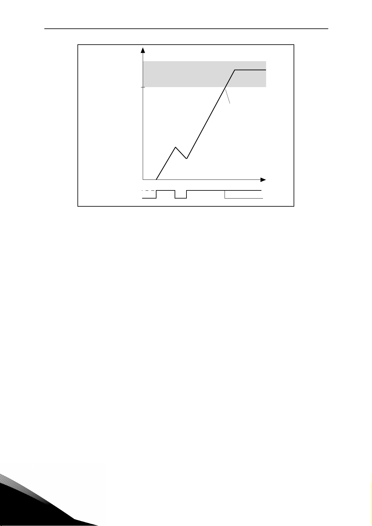
P4.1, P4.2
[Hz]
[t]
P4.3
P4.3
P3.23 PANEL POTENTIOMETER MIN CORRECTION
P3.24 PANEL POTENTIOMETER MAX CORRECTION
Define the minimum and maximum correction on preset reference, controlled with potentiometer on panel.
3.4 Ramps
P4.1 ACCELERATION TIME 1
Ramp time, referred to variation from zero frequency to max frequency.
P4.2 D
Ramp time, referred to variation from max frequency to zero.
P4.3 R
When value is greater than zero, acceleration and deceleration ramps have a S shape.
The parameter is the time needed to reach full acc/dec.
When value is greater than zero, acceleration and deceleration ramps have a S shape. The parameter is the time needed to reach full acc/dec.
The start and end of acceleration and deceleration ramps can be smoothed with this parameter. Setting value 0 gives a linear ramp shape which causes acceleration and deceleration to
act immediately to the changes in the reference signal.
Setting value 0.1…10 seconds for this parameter produces an S-shaped acceleration/deceleration. The acceleration time is determined with parameters P1.3 and P1.4.
ECELERATION TIME 1
AMP 1 S SHAPE
Figure 5. Acceleration/deceleration (S-shaped).
These parameters are used to reduce mechanical erosion and current spikes when the reference is changed.
Service support: find your nearest Vacon service center at www.vacon.com
3
Page 44

vacon • 41 Parameter description
P4.4 ACCELERATION TIME 2
P4.5 D
P4.6 R
Ramp 2 is available only in Automatic mode, and is activated through digital signal defined in
P5.11. Automatic activation based on output frequency is also available.
P4.7 T
P4.8 T
If P4.7 is not 0, acceleration time 2 is activated when output frequency is higher than the value.
If P4.8 is not 0, deceleration time 2 is activated when output frequency is higher than the value.
P4.9 Q
Specific ramp time for quick stop. To see description of P2.5 for details about the function.
ECELERATION TIME 2
AMP 2 S SHAPE
HRESHOLD ACCELERATION TIME 2
HRESHOLD DECELERATION TIME 2
UICK STOP DECELERATION TIME
3
Page 45

Parameter description vacon • 42
3.5 Input functions
P5.1 START SIGNAL 1
P5.2 S
TART SIGNAL 2
Signals for start and direction. Logic is selected with P2.1.
0: Function not used
1: ASi Output 1
2: ASi Output 2
3: ASi Output 3
4: ASi Output 4
5: Sensor 1
6: Sensor 2
7: Sensor 3
8: Sensor 4
P5.3 P
P5.4 P
P5.5 P
RESET SPEED BIT0
RESET SPEED BIT1
RESET SPEED BIT2
Signals for preset speed selection, with binary coding.
Required action Activated frequency
B2 B1 B0 Preset frequency 0
B2 B1 B0 Preset frequency 1
B2 B1 B0 Preset frequency 2
B2 B1 B0 Preset frequency 3
B2 B1 B0 Preset frequency 4
B2 B1 B0 Preset frequency 5
B2 B1 B0 Preset frequency 6
B2 B1 B0 Preset frequency 7
Table 45. Selection of preset frequencies; = input activated
P5.6 F
AULT RESET
Active on rising edge.
Note: an automatic fault reset is triggered when Manual mode is activated on operator panel.
P5.7 F
ORCE BRAKE
Signal high opens the mechanical brake.
Service support: find your nearest Vacon service center at www.vacon.com
3
Page 46

vacon • 43 Parameter description
P5.8 EXTERNAL FAULT, CLOSE
Fault is triggered by high signal.
P5.9 E
XTERNAL FAULT, OPEN
Fault is triggered by low signal.
P5.10 R
UN ENABLE
Motor stops by coasting if the signal is missing.
Note: The drive is not in Ready state when Enable is low.
P5.11 R
AMP TIME 2 SELECTION
Ramp 2 is selected by signal high.
P5.12 MOTOR POTENTIOMETER UP
Signal high causes speed increase.
P5.13 M
OTOR POTENTIOMETER DOWN
Signal high causes speed reduction.
P5.14 Q
UICK STOP OPEN
Signal low forces the drive to stop, ramping down with the time defined in P4.9.
To see description of P2.5 for details about the function.
P5.15 Q
UICK STOP CLOSE
Similar to P5.14, but in this case Quick Stop is activated by high signal.
3
Page 47

Parameter description vacon • 44
3.6 Output functions
P6.1 ASI INPUT 1
P6.2 AS
P6.3 AS
P6.4 AS
I INPUT 2
I INPUT 3
I INPUT 4
Meaning of ASi input bit.
0: not used
1: Sensor 1
2: Sensor 2
3: Sensor 3
4: Sensor 4
5: Ready + Automatic (both conditions are needed to have the bit high)
6: Run
7: Fault
8: Fault or warning
9: Reverse
10: Running feedback
1)
11: Automatic mode
12: At speed (reference reached, from internal motor control)
13: Output freq superv
14: Output current superv
15: Brake command
16: Quick stop active
1)
when Automatic mode is not assigned to a specific Input, Running Feedback input includes
also information about Automatic.
Automatic Run Output frequency <= Setpoint Feedback
0- - 0
10 - 1
11 0 0
11 1 1
Service support: find your nearest Vacon service center at www.vacon.com
3
Page 48

vacon • 45 Parameter description
P6.5 RO1 SIGNAL SELECTION
P6.6 RO2
Function for internal relays.
0: not used
1: Ready
2: Run
3: Fault
4: Fault inverted
5: Fault or warning
6: Reverse
7: At speed (motor control feedback)
8: Output freq superv
9: Output current superv
10: ASi Output 1
11: ASi Output 2
12: ASi Output 3
13: ASi Output 4
SIGNAL SELECTION
Note: relay terminals are not accessible in standard V20X+D drive.
P6.7 RO1 ON
P6.8 RO1 OFF DELAY
Possible delays for ON/OFF transitions.
P6.9 RO1 INVERSION
Inversion of relay state.
P6.10 RO2 ON DELAY
P6.11 RO2 OFF DELAY
Possible delays for ON/OFF transitions.
DELAY
3
Page 49

Parameter description vacon • 46
3.7 Mechanical brake
P7.1 BRAKE OPEN FREQUENCY
P7.2 BRAKE OPEN CURRENT
Thresholds that must be reached for external brake open at start.
If P7.1 > 0Hz, frequency reference is internally limited to P7.1 + 0.1 Hz until the brake is released.
Fault 56 Brake Time Out is triggered if the thresholds in P7.1 and P7.2 are not reached within
3s from Start command.
P7.3 B
The brake is closed when the start command is low and output frequency is below this threshold. Possible delay in P7.4.
P7.4 B
Respected in any stop condition (quick, fault, no enable), apart direct control from ASi input,
when the signal goes low.
RAKE CLOSE FREQUENCY
RAKE CLOSE DELAY
Service support: find your nearest Vacon service center at www.vacon.com
3
Page 50

vacon • 47 Parameter description
3.8 Supervisions
P8.1 RUNNING FEEDBACK TOLERANCE
When output frequency has reached this percentage of reference, running feedback is set high.
P8.2 F
REQUENCY SUPERVISION FUNCTION
0: No supervision
1: Low limit
2: High limit
P8.3 F
REQUENCY SUPERVISION LIMIT
Threshold value.
P8.4 C
URRENT SUPERVISION LIMIT
Threshold value.
P8.5 P
ROCESS DISPLAY SOURCE
Monitor V3.9 can show a process value, proportional to a variable measured by the drive.
Source variables are:
0: output frequency (max: Fmax)
1: motor speed (max: Speed at Fmax)
2: motor torque (max: Tnom)
3: motor power (max: Pnom)
4: motor current (max: Inom)
P8.6 P
ROCESS DISPLAY DECIMAL DIGITS
Number of decimals shown on monitor V3.9 and also on parameter P8.7.
P8.7 P
ROCESS DISPLAY MAX VALUE
Value shown on V3.9 when source variable is at its maximum. Proportionality is kept if the
source overtakes the maximum.
3
Page 51

Parameter description vacon • 48
U[V]
f[Hz]
Default: Nominal
voltage of the motor
Linear
Squared
Field
weakening
point
Default:
Nominal frequency
of the motor
3.9 Motor control
P9.1 FIELD WEAKENING POINT
Output frequency corresponding to max voltage.
Note: if P1.2 Nominal Frequency is changed, P9.1 will be set at same value.
P9.2 F
Motor voltage when frequency is above FWP, defined as % of nominal voltage.
Note: if P1.1 Nominal Voltage is changed, P9.2 will be set at 100%.
P9.3 U/
0: linear
The voltage of the motor changes linearly as a function of output frequency
from zero frequency voltage P9.6 to the field weakening point (FWP)
voltage P9.2 at FWP frequency P9.1 This default setting should be
used if there is no special need for another setting.
IELD WEAKENING POINT VOLTAGE
F SELECTION
1: quadratic
(from voltage P9.6 at 0Hz, to voltage P9.2 at P9.1 frequency)
The voltage of the motor changes from zero point voltage P9.6 following a squared curve form
from zero to the field weakening point P9.2. The motor runs under-magnetized below the field
weakening point and produces less torque. Squared U/f ratio can be used in applications where
torque demand is proportional to the square of the speed, e.g. in centrifugal fans and pumps.
Service support: find your nearest Vacon service center at www.vacon.com
Figure 6. Linear and quadratic curve of the motor voltage.
3
Page 52

vacon • 49 Parameter description
U[V]
f[Hz]
P2
P3
P1
Default: Nominal
voltage of the motor
Linear
Field
weakening
point
Default:
Nominal frequency
of the motor
2: programmable
The U/f curve can be programmed with three different points: Zero frequency voltage (P1),
Midpoint voltage/frequency (P2) and Field weakening point (P3).
Programmable U/f curve can be used if more torque is needed at low frequencies. The optimal
settings can automatically be achieved with Motor identification run.
Note: motor identification automatically sets this parameter to 2.
P9.4 U/F MID POINT FREQUENCY
Enabled if P9.3= 2.
Note: motor identification automatically sets this parameter.
P9.5 U/
Enabled if P9.3= 2.
Note: motor identification automatically sets this parameter.
P9.6 V
Motor voltage at frequency zero.
Note: motor identification automatically sets this parameter.
P9.7 R
Voltage drop on stator windings, at motor nominal current, defined as % of nominal voltage.
Value affects motor torque estimation, slip compensation and voltage boost.
Figure 7. Programmable curve.
F MID POINT VOLTAGE
OLTAGE AT F0
S VOLTAGE DROP
3
Page 53

Parameter description vacon • 50
Note: it is suggested not to program manually the value, but to perform motor identification
procedure that automatically sets the value.
P9.8 S
WITCHING FREQUENCY
PWM frequency. Values above default can cause thermic overload of the drive.
P9.9 D
ROOPING MODE
0: constant.
Load drooping factor is constant through the whole frequency range.
1: speed dependent.
Load drooping is reduced linearly from nominal frequency to zero frequency.
P9.10 D
ROOP FILTER TIME
Time constant of the low pass filter applied to droop frequency variation.
P9.11 B
RAKE CHOPPER
0: Chopper disabled
1: Chopper enabled in Run state
2: Chopper enabled in Ready state
P9.12 B
RAKE CHOPPER LEVEL
DC link voltage above which chopper is activated.
P9.13 DC
BRAKING CURRENT
DC current injected at start or stop.
P9.14 S
TOP DC CURRENT TIME
Time for DC current injection at stop.
P9.15 S
TOP DC CURRENT FREQUENCY
DC current is injected below this frequency.
P9.16 S
TART DC BRAKE TIME
Time for DC current injection at start.
P9.17
OVERVOLTAGE REGULATOR
Overvoltage regulator automatically increases deceleration ramp time if the internal DC link
voltage is too high.
0: enabled
1: disabled
Service support: find your nearest Vacon service center at www.vacon.com
3
Page 54

vacon • 51 Parameter description
P9.18 UNDERVOLTAGE REGULATOR
Undervoltage regulator automatically decelerates the motor if the internal DC link voltage is
too low.
0: enabled
1: disabled
P9.19
Switching frequency regulator automatically decreases the PWM frequency if the unit temperature is too high.
0: enabled
1: disabled
SWITCHING FREQUENCY REGULATOR
3
Page 55

Parameter description vacon • 52
f
I
Par. P1.6
Par. P10.4
Stall area
3.10 Protections
P10.1 EARTH FAULT
0: No action
1: Warning
2: Fault
Output currents sum not zero.
P10.2 M
0: No action
1: Warning
2: Fault
This is an overload protection. Stall is recognized by maximum motor current (=P1.5) and low
output frequency.
OTOR STALL FAULT
Figure 8. Stall characteristic settings.
P10.3 STALL TIME LIMIT
This time can be set between 0.0 and 300.0 s.
This is the maximum time allowed for all stage. the stall time is counted by an internal up/down
counter. If the stall time counter value goes above this limit the protection will cause a trip.
Service support: find your nearest Vacon service center at www.vacon.com
3
Page 56
vacon • 53 Parameter description
Par. P10.3
Trip area
Time
Stall time counter
Stall•
No stall
Trip/warning
par. P10.2
Figure 9. Stall time count.
P10.4 STALL FREQUENCY LIMIT
Stall is recognized when the current limiter has reduced the output frequency below P10.4, for
the time in P10.3.
P10.5 U
0: No action
1: Warning
2: Fault
Underload is recognized when torque is above the minimum curve defined by P10.6 and P10.7,
for the programmed time P10.8.
P10.6
The torque limit can be set between 10.0-150.0% x T
This parameter gives the value for the minimum torque allowed when the output frequency is
above the field weakening point.
NDERLOAD FAULT
UNDERLOAD FAULT: FIELD WEAKENING AREA LOAD
.
nMotor
3
Page 57

Parameter description vacon • 54
Par.
P10.6
Par.
P10.7
f
5 Hz
Underload area
Torque
Fieldweakening
point
Par. P10.8
Trip area
Time
Underload time counter
Underload•
No underl.
Trip /w ar ni ng
par. P10.5
Figure 10. Underload characteristic settings.
P10.7 UNDERLOAD FAULT: ZERO FREQUENCY LOAD
P10.8 UNDERLOAD FAULT: TIME LIMIT
Definition of minimum load at nominal and zero speed zero. Fault condition delay. This time
can be set between 1.0 and 300.0 s.
This is the maximum time allowed for an underload state to exist. An internal up/down counter
counts the accumulated underload time. If the underload counter value goes above this limit
the protection will cause a trip according to parameter P10.5). If the drive is stopped the underload counter is reset to zero.
Figure 11. Underload time counter.
Service support: find your nearest Vacon service center at www.vacon.com
3
Page 58

vacon • 55 Parameter description
f
f
n
Par.
P10.11=40%
0
I
T
100%
Overload area
P
cooling
Corner freq
P10.9 MOTOR THERMAL FAULT
0: No action
1: Warning
2: Fault
This is a software protection, based on time integral of current.
P10.10 M
Change if environment is not standard.
P10.11 M
Defines the cooling factor at zero speed in relation to the point where the motor is running at
nominal speed without external cooling. See Figure 12.
The default value is set assuming that there is no external fan cooling the motor. If an external
fan is used this parameter can be set to 90% (or even higher).
Setting this parameter does not affect the maximum output current of the drive which is determined by parameter P1.6 alone.
The corner frequency for the thermal protection is 70% of the motor nominal frequency (P1.2).
Set 100% if the motor has independent fan or cooling. Set 30-40% if the fan is on motor shaft.
OTOR AMBIENT TEMPERATURE FACTOR
OTOR THERMAL ZERO SPEED COOLING
3
Figure 12. Motor thermal current IT curve.
Page 59
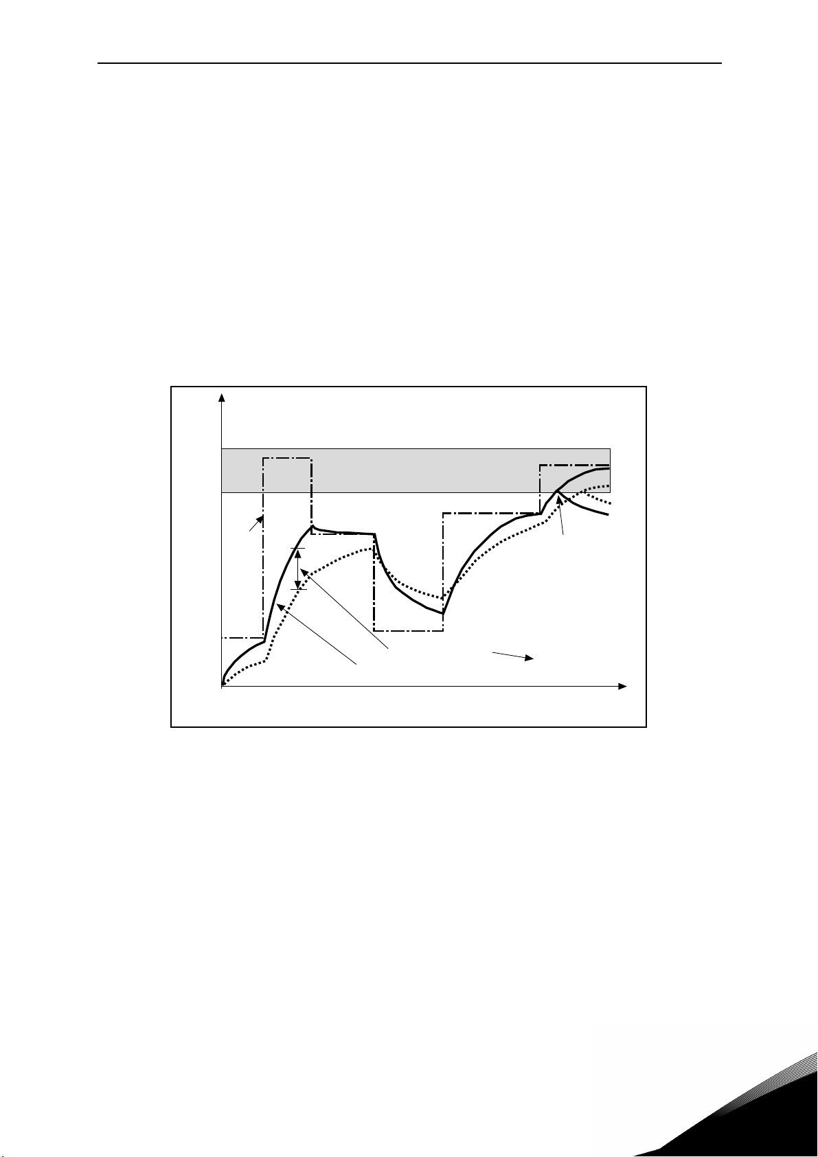
Parameter description vacon • 56
105%
Q = (I/IT)2 x (1-e
-t/T
)
I/I
T
Trip area
Motor temperature
Time
Motor temperature
Time constant T
*)
*)
Changes by motor size and
adjusted with P10.12
Fault/alarm
P10.9
Motor•
current
P10.12 MOTOR THERMAL TIME CONSTANT
Time at nominal current, to reach nominal temperature.
The time constant is the time within which the calculated thermal stage has reached 63% of its
final value. The bigger the frame and/or slower the speed of the motor, the longer the time
constant.
The motor thermal time is specific to the motor design and it varies between different motor
manufacturers. The default value of the parameter varies from size to size.
If the motor's t6-time (t6 is the time in seconds the motor can safely operate at six times the
rated current) is known (given by the motor manufacturer) the time constant parameter can be
set basing on it. As a rule of thumb, the motor thermal time constant in minutes equals to 2*t6.
If the drive is in stop stage the time constant is internally increased to three times the set parameter value. The cooling in stop stage is based on convection and the time constant is increased.
P10.13 FIELDBUS COMMUNICATION FAULT
0: No action
1: Warning
2: Fault
Communication lost.
P10.14 T
0: No action
1: Warning
2: Fault
Impedance on thermistor input is above fault threshold.
Service support: find your nearest Vacon service center at www.vacon.com
HERMISTOR FAULT
Figure 13. Motor temperature calculation.
3
Page 60

vacon • 57 Parameter description
P10.15 RESPONSE TO SAFE TORQUE OFF
0: No action
1: Warning
2: Fault, not stored in history
3: Fault, stored in history
Safe Torque Off disabled.
P10.16 I
0: No action
1: Warning
2: Fault
Input phase missing.
P10.17 I
Sensitivity for input phases check
0: internal value (default)
1-75: sensitivity from maximum(1) to minimum (75)
P10.18 M
Setting of estimated motor temperature at power on
0: initialized at minimum value
1: initialized at constant value from P10.19
2: initialized at last previous value, with P10.19 used as factor
NPUT PHASE FAULT
NPUT PHASE FAULT RIPPLE LIMIT
OTOR TEMPERATURE INITIALIZATION
P10.19 M
If P10.18= 1, motor temperature is initialized with this value.
If P10.18= 2, motor temperature is initialized with last previous value, multiplied by this value
as % factor.
OTOR TEMPERATURE INITIAL VALUE
3
Page 61

Parameter description vacon • 58
3.11 Automatic reset
P11.1 AUTOMATIC RESET
0: Disabled
1: Enabled
The automatic reset function deletes fault state when the fault cause has been eliminated and
the wait time P11.2 has elapsed. Parameter P11.4 determines the maximum number of automatic resets that can be effected during the trial time set by parameter P11.3. The time count
starts from the first automatic reset. If the number of faults detected during the trial time exceeds the values of trials, the fault status becomes permanent and a reset command is needed.
P11.2 W
Time after which the converter attempts to restart the motor automatically after the fault has
been eliminated.
P11.3 T
Total time for reset attempts.
P11.4 N
Trials attempted during time P11.3.
P11.5 R
Start function after an automatic fault reset.
0: Start with ramp
1: Flying start
2: As defined in P2.3
AIT TIME
RIAL TIME
UMBER OF TRIALS
ESTART FUNCTION
Service support: find your nearest Vacon service center at www.vacon.com
3
Page 62

vacon • 59 Parameter description
3.12 Non-ASi fieldbus
P12.1 TO
P12.8 FIELDBUS DATA OUT 1 - 8 SEL
Parameter couples read only variables to output process data 1.
0: not used
1: output frequency
2: motor speed
3: motor current
4: motor voltage
5: motor torque
6: motor power
7: DC link voltage
8: active fault code
9: ASi inputs (ASi emulation)
10: sensors state (binary)
P12.9 AS
Parameter defines the input process data possibly used to emulate ASi outputs.
0: not used
1: PDI1
2: PDI2
3: PDI3
4: PDI4
5: PDI5
I OUTPUTS EMULATION
3
Page 63

Parameter description vacon • 60
3.12.1 Modbus fieldbus mapping
3.12.1.1 Fieldbus Data IN: Master -> Slave
Modbus
register
2001 Control word Drive control
2002 General control word Not used
2003 Speed reference Reference
2004 Fieldbus Data IN 1 Programmable
2005 Fieldbus Data IN 2 Programmable
2006 Fieldbus Data IN 3 Programmable
2007 Fieldbus Data IN 4 Programmable
Name Description Range
Binary coded:
b0: Run
b1: Reverse
b2: Fault Reset (on edge)
0...10000 as 0,00...100,00%
of Min freq. - Max freq.
range
0...10000
It can emulate ASi Output
(See P12.9)
0...10000
It can emulate ASi Output
(See P12.9)
0...10000
It can emulate ASi Output
(See P12.9)
0...10000
It can emulate ASi Output
(See P12.9)
0...10000
2008 Fieldbus Data IN 5 Programmable
2009 Fieldbus Data IN 6 Not used 2010 Fieldbus Data IN 7 Not used 2011 Fieldbus Data IN 8 Not used -
Table 46. Modbus Data inputs. They can vary depending on fieldbus used (See specific
fieldbus option board installation manual).
Notes:
• CW b0 Run is acquired on edge, only if the drive is in Ready state (see Status Word b0)
and actual control place is Fieldbus.
• CW b2 Fault Reset is active even if control place is not the Fieldbus.
• Fieldbus different from Modbus have their own Control Word (see manual of the specific
fieldbus board).
It can emulate ASi Output
(See P12.9)
Service support: find your nearest Vacon service center at www.vacon.com
3
Page 64

vacon • 61 Parameter description
3.12.1.2 Fieldbus Data OUT: Slave ->Master
Modbus
register
2101 Status word Drive state
2102 General Status word Drive state
2103 Actual speed(*) Actual speed
2104 Fieldbus Data OUT 1 Programmable See P12.1
Name Description Range
Binary coded:
b0: Ready
b1: Run
b2: Reverse
b3: Fault
b4: Warning
b5: Freq. reference reached
b6: Zero speed
b0: Ready
b1: Run
b2: Reverse
b3: Fault
b4: Warning
b5: Freq. reference reached
b6: AUTO mode
b7: MANUAL mode
b8: Brake command
0...10000 as 0,00...100,00%
of Min freq. - Max freq.
range
2105 Fieldbus Data OUT 2 Programmable See P12.2
2106 Fieldbus Data OUT 3 Programmable See P12.3
2107 Fieldbus Data OUT 4 Programmable See P12.4
2108 Fieldbus Data OUT 5 Programmable See P12.5
2109 Fieldbus Data OUT 6 Programmable See P12.6
2110 Fieldbus Data OUT 7 Programmable See P12.7
2111 Fieldbus Data OUT 8 Programmable See P12.8
Table 47. Modbus data outputs. They can vary depending on fieldbus used (See specific
fieldbus option board installation manual).
Notes:
• Fieldbus different from Modbus have their own Status Word (see manual of the specific
fieldbus board).
3
Page 65

Parameter description vacon • 62
3.13 Analogue Output
P13.1 ANALOGUE OUTPUT FUNCTION
Signal coupled to analogue output.
Selection Selection name Value corresponding to maximum output
0 Not used output always fixed at 100%
1 Frequency reference Max frequency(P3.2)
2 Output frequency Max frequency(P3.2)
3 Motor speed Motor nominal speed
4 Motor current Motor nominal current
5 Motor torque Motor nominal torque (absolute value)
6 Motor power Motor nominal power (absolute value)
Table 48. Analogue output signals.
P13.2 A
0: 0V
1: 2V
P13.3 A
Scaling factor.
P13.4 A
Time constant of low pass filter.
Note: analogue output terminals are not accessible in standard Vacon 20X+D drive.
NALOGUE OUTPUT MINIMUM SIGNAL
NALOGUE OUTPUT SCALING
NALOGUE OUTPUT FILTER TIME
3.14 User interface
P14.1 PARAMETERS ACCESS LEVEL
See chapter 1
0: Basic
1: Advanced
2: Service
P14.2 P
0: Edit enabled
1: Edit disabled
Service support: find your nearest Vacon service center at www.vacon.com
ARAMETERS LOCK
3
Page 66

vacon • 63 Parameter description
3
Page 67

Fault tracing vacon • 64
4. FAULT TRACING
Fault
code
1
2
3
8
9
10
13
14
Fault name Possible cause Remedy
AC drive has detected too high a cur-
Overcurrent
Overvoltage
Earth fault
System fault
Undervoltage
rent (>4*I
• sudden heavy load increase
• short circuit in motor cables
• unsuitable motor
The DC-link voltage has exceeded the
limits defined.
• too short a deceleration time
• brake chopper is disabled
• high overvoltage spikes in sup-
• Start/Stop sequence too fast
Current measurement has detected
that the sum of motor phase current is
not zero.
• insulation failure in cables or
Component fault
Malfunction
DC-link voltage is under the voltage
limits defined.
• most probable cause: too low a
• AC drive internal fault
• defect input fuse
• external charge switch not
) in the motor cable:
H
ply
motor
supply voltage
closed
NOTE! This fault is activated only if the
drive is in Run state.
Input phase Input line phase is missing.
AC drive undertemperature
AC drive overtemperature
Too low temperature measured in
power unit’s heatsink or board. Heatsink temperature is under -10°C.
Too high temperature measured in
power unit’s heatsink or board. Heatsink temperature is over 100°C.
Check loading.
Check motor.
Check cables and connections.
Make identification run.
Check ramp times.
Make deceleration time longer.
Use brake chopper or brake resistor (available as options).
Activate overvoltage controller.
Check input voltage.
Check motor cables and motor.
Reset the fault and restart.
Should the fault re-occur, contact
the distributor near to you.
In case of temporary supply voltage break reset the fault and
restart the AC drive. Check the
supply voltage. If it is adequate, an
internal failure has occurred.
Contact the distributor near to
you.
Check supply voltage, fuses and
cable.
Check the ambient temperature.
Check the correct amount and
flow of cooling air.
Check the heatsink for dust.
Check the ambient temperature.
Make sure that the switching frequency is not too high in relation
to ambient temperature and
motor load.
15
Motor stalled Motor is stalled. Check motor and load.
Table 49. Fault codes and descriptions.
Service support: find your nearest Vacon service center at www.vacon.com
4
Page 68

vacon • 65 Fault tracing
Fault
code
16
17
19
25
27
30
35
41
50
51
52
53
54
55
56
57
Fault name Possible cause Remedy
Decrease motor load.
Motor overtemperature
Motor Underload
Power overload Supervision for drive power
Watchdog
Back EMF
STO fault
Application
error
IGBT temp
4 mA fault
(Analog input)
External fault
Keypad
communication
fault
Fieldbus
communication
fault
Fieldbus
Interface error
Wrong run
command
Brake time out
Identification Identification alarm
Motor is overloaded.
Motor is under loaded Check load.
Error in the microprocessor monitoring
Malfunction
Component fault
Protection of unit when starting with
rotating motor
Safe torque off signal does not allow
drive to be set as ready
The application is not working
IGBT temperature (UnitTemperature +
I2T) too high
Selected signal range: 4...20 mA (see
Application Manual)
Current less than 4 mA
Signal line broken detached
The signal source is faulty
Error message on digital input. The
digital input was programmed as an
input for external error messages. The
input is active.
The connection between the control
keypad and the frequency converter is
broken.
The data connection between the fieldbus master and fieldbus board is broken
Defective option board or slot Check board and slot.
Wrong run alarm and stop command
Threshold for brake open are not
reached
If no motor overload exists, check
the temperature model parame-
ters.
Drive power is to high: decrease
load.
Reset the fault and restart.
If the fault occurs again, please
contact your closest Vacon repre-
sentative.
Reset the fault and restart.
Should the fault re-occur, contact
the distributor near to you.
Reset the fault and restart.
Should the fault re-occur, contact
the distributor near to you.
Please contact your closest Vacon
representative.
Check loading.
Check motor size.
Make identification run.
Check the analog input’s current
source and circuit.
Check the programming and
check the device indicated by the
error message.
Check the cabling for the respec-
tive device as well.
Check keypad connection and key-
pad cable.
Check installation and fieldbus
master.
Run forward and backward are
activated at the same time
Check the settings of the mechan-
ical brake and of the motor.
Motor identification has not been
successfully completed
4
Table 49. Fault codes and descriptions.
Page 69

Fault tracing vacon • 66
Fault
code
63
64
Fault name Possible cause Remedy
The drive has been stopped with
Quick Stop Quick Stop activated
ASi communication not OK
ASi board is not working properly. Check the state on monitor V1.3
Table 49. Fault codes and descriptions.
Quick Stop digital input or Quick
Stop command by fieldbus
Service support: find your nearest Vacon service center at www.vacon.com
4
Page 70

Page 71

Page 72

Find your nearest Vacon office
on the Internet at:
www.vacon.com
Document ID:
Manual authoring:
documentation@vacon.com
Vacon Plc.
Runsorintie 7
65380 Vaasa
Finland
Subject to change without prior notice
© 2013 Vacon Plc.
Rev. A
 Loading...