

Page 1

vacon®20 cp/x
ac drives
Solar pump application manual
Page 2

Page 3

vacon • 0
INDEX
Document ID: DPD01601E
Version release date: 4.2.15
Corresponds to application package ACIT1163V107.vcx
1. Safety............................................................................................................... 2
1.1 Danger ............................................................................................................................... 2
1.2 Warnings ........................................................................................................................... 2
2. Solar pump Application ................................................................................... 4
2.1 Specific functions of Vacon Solar pump application ........................................................ 4
2.2 Example of control connections ....................................................................................... 5
2.3 Optional boards ................................................................................................................. 7
2.3.1 Option board installation................................................................................................... 9
3. Description of Groups .................................................................................... 14
3.1 Keypad Reference: Menu REF ........................................................................................ 14
3.2 Monitor group: menu MON ............................................................................................. 15
3.2.1 Drive Monitors ................................................................................................................. 15
3.2.2 Solar Monitors................................................................................................................. 16
3.3 Parameter Groups: Menu PAR ....................................................................................... 17
3.3.1 Group Basic Parameters: Menu PAR G1 ........................................................................ 18
3.3.2 Group Advanced Settings: Menu PAR G2........................................................................ 20
3.3.3 Group Analogue inputs: Menu PAR G3 ........................................................................... 21
3.3.4 Group Digital inputs: Menu PAR G4 ................................................................................ 22
3.3.5 Group Digital outputs: Menu PAR G5.............................................................................. 24
3.3.6 Group Analogue outputs: Menu PAR G6 ......................................................................... 25
3.3.7 Group Supervisions: Menu PAR G7................................................................................. 26
3.3.8 Group Motor Control: Menu PAR G8............................................................................... 27
3.3.9 Group Protections: Menu PAR G9................................................................................... 28
3.3.10 Group Autoreset: Menu PAR G10.................................................................................... 31
3.3.11 Group Fieldbus: Menu PAR G11...................................................................................... 32
3.3.12 Group PID Control: Menu Par G12.................................................................................. 33
3.3.13 Group Solar: Menu PAR G14........................................................................................... 35
3.3.14 Group Flow meter: Menu PAR G15................................................................................. 36
3.4 System parameters, Faults and History faults: Menu FLT ............................................ 37
4. Parameter description................................................................................... 40
4.1 Basic Parameters............................................................................................................ 40
4.2 Advanced settings ........................................................................................................... 43
4.3 Analogue inputs............................................................................................................... 48
4.4 Digital inputs ................................................................................................................... 53
4.5 Digital outputs ................................................................................................................. 55
4.6 Analogue Output..............................................................................................................57
4.7 Supervisions .................................................................................................................... 58
4.8 Motor control................................................................................................................... 59
4.9 Protections ...................................................................................................................... 63
4.10 Autoreset ......................................................................................................................... 69
4.11 Fieldbus ........................................................................................................................... 70
4.11.1 Fieldbus mapping............................................................................................................ 71
4.12 PID Control ...................................................................................................................... 74
4.13 Solar ................................................................................................................................ 76
4.13.1 Start Settings................................................................................................................... 76
4.13.2 MPPT ............................................................................................................................... 76
4.14 Flow meter ...................................................................................................................... 81
Rev. E
Service support: find your nearest Vacon service center at www.vacon.com
Page 4

vacon • 1
5. Fault tracing .................................................................................................. 82
Page 5
Safety vacon • 2
1. SAFETY
This manual contains clearly marked warning information which is intended for your personal
safety and to avoid any unintentional damage to the product or connected appliances.
Before installing, commissioning or using the frequency converter, please read the warning
information contained in Vacon 20X Installation Manual.
Please read the following additional safety instructions carefully.
Only Vacon authorized, trained and qualified personnel are allowed to install, operate and
maintain the drive.
1.1 Danger
These warnings are intended to personnel responsible for grounding the frequency converter.
Ignoring the following instructions can be extremely dangerous and may cause
death or severe injury.
Ground the frequency converter to ensure personnel safety and to reduce electromagnetic interference.
After disconnecting the AC drive from the mains or from the DC input supply,
wait until the indicators on the keypad go out (if no keypad is attached, see the
indicators on the cover). Wait an additional 30 seconds before starting any work
on the connections of Vacon 20X Drive. After expiration of this time, use measuring equipment to absolutely ensure that no
absence of voltage before starting any electrical work!
1.2 Warnings
The touch current of VACON
dard EN61800-5-1, a reinforced protective ground connection must be ensured.
See Vacon 20X Installation Manual for further information.
Never work on the photovoltaic generator or frequency converter and its input/
output cables when the frequency converter is connected to the mains or to the
photovoltaic generator.
Before performing any measurement on the frequency converter, disconnect or
isolate the mains supply voltage or the DC input supply.
Do not touch the components on the frequency converter or on the string box
cabinet that have high DC voltage.
voltage is present.
®
20X drives exceeds 3.5mA AC. According to stan-
Always ensure
The photovoltaic generator cells exposed to light supply DC voltage even at low
light intensity.
Service support: find your nearest Vacon service center at www.vacon.com
1
Page 6

vacon • 3 Safety
1
Page 7

Solar pump Application vacon • 4
2. SOLAR PUMP APPLICATION
The VACON® 20 CP/X drive contains a preloaded application for instant use.
The parameters of this application are listed in chapter 3.3 of this manual and explained in
more detail in chapter 4.
2.1 Specific functions of Vacon Solar pump application
The Vacon Solar Pump allows flexible use of VACON® 20 CP/X frequency converters. This dedicated application SW was developed to drive a Solar Pump with an optimized MPPT (Maximum
Power Point Tracking) for 20X supplied by Solar Panels.
The MPPT is based on 4 parallel algorithms:
• Feed-Forward Controller (to follow the radiation variations)
• Correction Controller (to compensate the temperature variations)
• Oscillation Damping Regulator (to prevent the panel entering in the “current source”
branch of the characteristic)
• Local Maxima logic (to prevent the regulator from being trapped in a local maximum
lower than absolute maximum)
Features
The MPP Tracker controls DC voltage reference in order to find the maximum power.
The drive can be controlled through I/O terminals, a fieldbus or the optional keypad.Two programmable control places and sources for the frequency reference are available, for easy local/remote control.
Frequency reference can be direct (analogue input, preset speeds or fieldbus) or controlled by
the internal PID regulator.
All the functionalities can be controlled through a fieldbus.
The motor identification function allows automatic optimization of the voltage/frequency curve,
for a optimal torque response also at low motor speed.
It is possible to install one optional board for I/O expansion.
Underload protection can be managed by measuring Motor torque (standard sensorless mode)
or by measuring the water flow with a flow meter sensor. This sensor can be an analogue signal or a digital input. With this sensor it is possible to measure the water flow [litres/min] and
the total volume of the water flow [m
Sleep mode can be enabled or disabled with a parameter.
Digital inputs can be used to measure water levels (minimum and maximum).
3
].
Service support: find your nearest Vacon service center at www.vacon.com
2
Page 8
vacon • 5 Solar pump Application
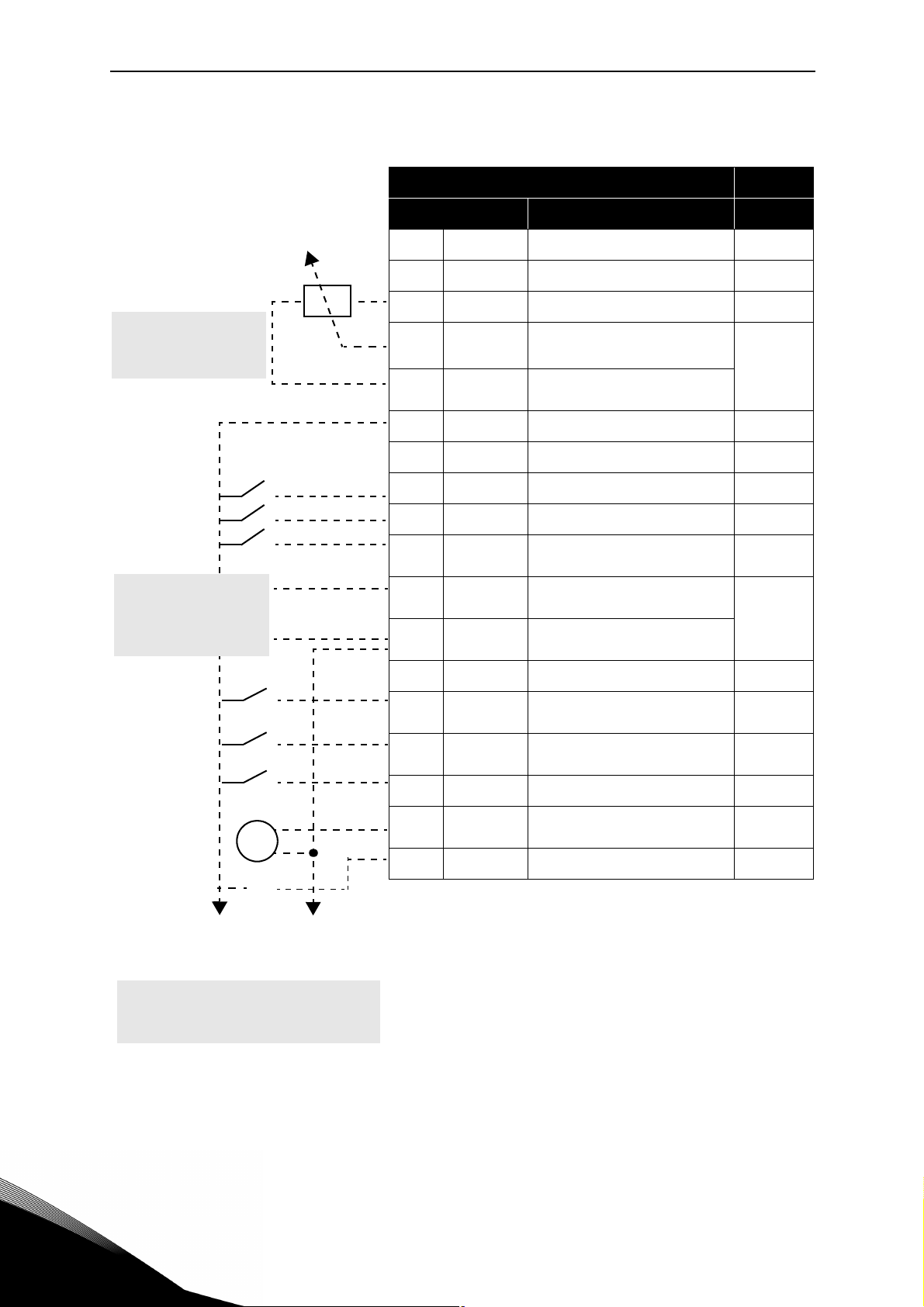
2.2 Example of control connections
Standard I/O terminals
Terminal Signal Default
RS485 Serial bus, negative
A
RS485 Serial bus, positive
B
+10 Vref Reference output
1
Reference potentiometer
1...10 kΩ
PID Actual value
4...20mA/0...10V
(programmable)
AI1+
2
AI1-/GND
3
24Vout 24V aux. voltage
6
DIN COM Digital input common
7
DI1 Digital input 1 Start 1
8
DI2 Digital input 2 Start 2
9
DI3 Digital input 3
10
AI2+
4
AI2-/GND
5
DO1- Digital Output Common
13
DI4 Digital input 4
14
DI5 Digital input 5
15
Analogue input,
voltage or current
Analogue input common
(current)
Analogue input,
voltage or current*
Analogue input common
(current)
*
(default
Voltage)
Freq.
Reference
Fault
reset
(def.
Current)
PID
feedback
Preset
Speed B0
Ext. fault
Closed
V
X1
Table 1. Connection example, standard I/O terminals.
To Relay terminals
1 or 2
DI6 Digital input 6 Not used
16
AO1+ Analogue signal (+output)
18
DO1+ Digital output +
20
*
Selectable with DIP switches, see VACON® 20 CP/X
Installation Manual
Output
frequency
Fault
2
Page 9

Solar pump Application vacon • 6
From
Standard I/O terminals
From term.
#6
From term.
#3 or #5
FAU LT
Table 2. Connection example, Relay terminals
Relay terminals
Terminal Signal
22 RO1/2 CM
23 RO1/3 NO
24 RO1/1 NC
25 RO1/2 CM
26 RO1/3 NO
Default
Relay output 1 READY
Relay output 1 RUN
Service support: find your nearest Vacon service center at www.vacon.com
2
Page 10

vacon • 7 Solar pump Application
2.3 Optional boards
One optional I/O expansion board can be installed into the slot on the right side of the drive. The
following boards are supported:
OPTB1: 6 Digital Inputs-Outputs
The first 3 terminals are reserved as digital inputs (DIN7, DIN8, DIN9). The second 3 terminals
can be used as inputs (DIN10, DIN11, DIN12) or digital outputs (EO1, EO2, EO3). The number of
terminals used as input must be declared in parameter P2.24 (hidden if the board is not installed). This number determines the higher value for the selection of the digital input connected to a certain logical function. It also changes the visibility of parameters for the selection of
digital outputs function (P5.9, P5.10, P5.11).
OPTB2: 1 Thermistor Input, 2 Relays Outputs
Response to thermistor fault can be programmed with parameter P9.16. Relays functions can
be programmed with parameters P5.9, P5.10 (hidden if the board is not installed).
OPTB5: 3 Relays Outputs
Relays functions can be programmed with parameters P5.9, P5.10, P5.11 (hidden if the board
is not installed).
OPTB9: 5 Digital Inputs, 1 Relay Output
The higher value for the selection of the digital input (DIN7, DIN8, DIN9, DIN10, DIN11) connected to a certain logical function is set to 11. Relay functions can be programmed with parameters P5.9 (hidden if the board is not installed).
OPTBF: 1 Analogue Output, 1 Digital Output, 1 Relay Output
The digital output can be programmed with parameter P5.12. The digital output can be programmed with parameter P5.9. Parameters are hidden if the board is not installed.
OPTC3/E3: Profibus DPV1 fieldbus board
Vacon 20CP/X frequency converters can be connected to the PROFIBUS DP network using a
fieldbus board. The converter can then be controlled, monitored and programmed from the
Host system.OPTE3 option board also supports connection from DP Master (class 2) if DP-V1
is enabled. In this case, the Master class 2 can initiate a connection, read and write parameters
using the PROFIdrive Parameter Access service, and close the connection. The PROFIBUS DP
fieldbus is connected to the OPTE3 board using a 5-pin pluggable bus connector. The only difference between OPTE3 and OPTE5 boards is the fieldbus connector.
OPTC4 LonWorks fieldbus board
Vacon 20CP/X frequency converters can be connected to the LonWorks® network using a
fieldbus board. The converter can then be controlled, monitored and programmed from the
Host system.
OPTC5/E5: Profibus DPV1 fieldbus board (D-type connector)
Vacon 20CP/X frequency converters can be connected to the PROFIBUS DP network using a
fieldbus board. The converter can then be controlled, monitored and programmed from the
Host system.OPTE5 option board also supports connection from DP Master (class 2) if DP-V1
is enabled. In this case, the Master class 2 can initiate a connection, read and write parameters
using the PROFIdrive Parameter Access service, and close the connection. he PROFIBUS DP
fieldbus is connected to the OPTE5 board using a 9-pin female sub-D-connector. The only difference between OPTE3 and OPTE5 boards is the fieldbus connector.
2
OPTC6/E6: CanOpen fieldbus board
Vacon 20CP/X frequency converters can be connected to the CanOpen system using a fieldbus
board. The converter can then be controlled, monitored and programmed from the Host sys-
Page 11

Solar pump Application vacon • 8
tem. Vacon CanOpen Board is connected to the fieldbus through a 5-pin pluggable bus connector (board NXOPTC6/E6).
OPTC7/E7: DeviceNet fieldbus board
Vacon 20CP/X frequency converters can be connected to the DeviceNet using a fieldbus board.
The converter can then be controlled, monitored and programmed from the Host system. Vacon DeviceNet Board is connected to the fieldbus through a 5-pin pluggable bus connector
(board OPTC7/E7).
OPTCI: Modbus TCP fieldbus board
Vacon 20CP/X frequency converters can be connected to Ethernet using an Ethernet fieldbus
board OPTCI. Every appliance connected to an Ethernet network has two identifiers; a MAC address and an IP address. The MAC address (Address format: xx:xx:xx:xx:xx:xx ) is unique to the
appliance and cannot be changed. The Ethernet board's MAC address can be found on the
sticker attached to the board or by using the Vacon IP tool software NCIPConfig. Please find
the software installation at www.vacon.com. In a local network, IP addresses can be defined by
the user as long as all units connected to the network are given the same network portion of
the address. For more information about IP addresses, contact your Network Administrator.
Overlapping IP addresses cause conflicts between appliances.
OPTCP: Profinet fieldbus board
Vacon 20CP/X frequency converters can be connected to Ethernet using an Ethernet fieldbus
board OPTCP. Every appliance connected to an Ethernet network has two identifiers; a MAC
address and an IP address. The MAC address (Address format: xx:xx:xx:xx:xx:xx ) is unique to
the appliance and cannot be changed. The Ethernet board's MAC address can be found on the
sticker attached to the board or by using the Vacon IP tool software NCIPConfig. You can find
the software installation at www.vacon.com. In a local network, IP addresses can be defined by
the user as long as all units connected to the network are given the same network portion of
the address. For more information about IP addresses, contact your Network Administrator.
Overlapping IP addresses cause conflicts between appliances.
OPTCQ: Ethernet IP fieldbus board
Vacon 20CP/X frequency converters can be connected to Ethernet using an EtherNet/IP fieldbus board OPT-CQ. Every appliance connected to an Ethernet network has two identifiers; a
MAC address and an IP address. The MAC address (Address format: xx:xx:xx:xx:xx:xx) is
unique to the appliance and cannot be changed. The EtherNet/IP board's MAC address can be
found on the sticker attached to the board or by using the Vacon IP tool software NCIPConfig.
Please find the software installation at www.vacon.com. In a local network, IP addresses can
be defined by the user as long as all units connected to the network are given the same network
portion of the address. For more information about IP addresses, contact your Network Administrator. Overlapping IP addresses cause conflicts between appliances.
Service support: find your nearest Vacon service center at www.vacon.com
2
Page 12
vacon • 9 Solar pump Application
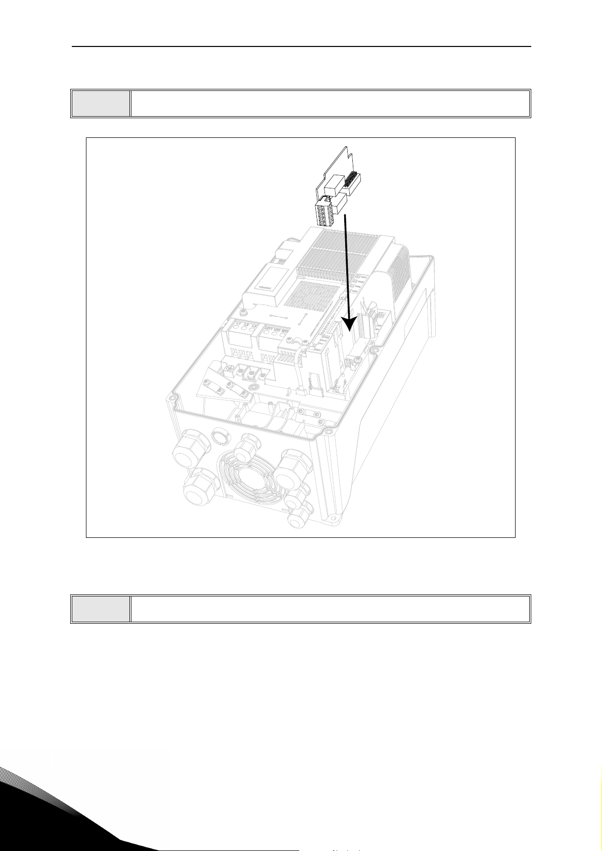
2.3.1 Option board installation
NOTE! It is not allowed to add or replace option boards or fieldbus boards on an AC
drive with the power switched on. This may damage the boards.
1
• Open the cover of the drive.
2
2
Figure 1. Opening the main cover, MU3 example.
The relay outputs and other I/O-terminals may have a dangerous control voltage
present even when the drive is disconnected from mains.
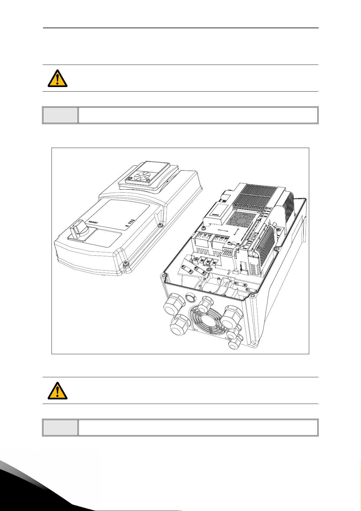
• Remove the option slot cover.
Page 13
Solar pump Application vacon • 10
Slot coding
OPT
dv
9116.emf
Figure 2. Removing the option slot cover.
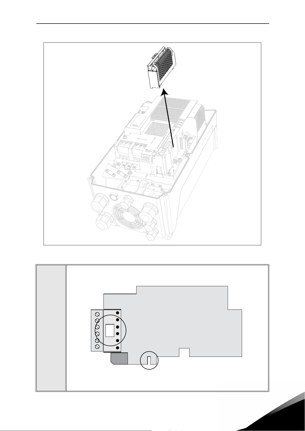
• Make sure that the sticker on the connector of the board says “dv” (dual
voltage). This indicates that the board is compatible with Vacon 20CP/X.
See below:
3
• NOTE: Incompatible boards cannot be installed on Vacon 20CP/X. Compatible boards have a slot coding that enable the placing of the board (see
above).
Service support: find your nearest Vacon service center at www.vacon.com
2
Page 14
vacon • 11 Solar pump Application
4
• Install the option board into the slot as shown in the picture below.
2
Figure 3. Option board installation.
• Mount the option slot cover.
5
Page 15
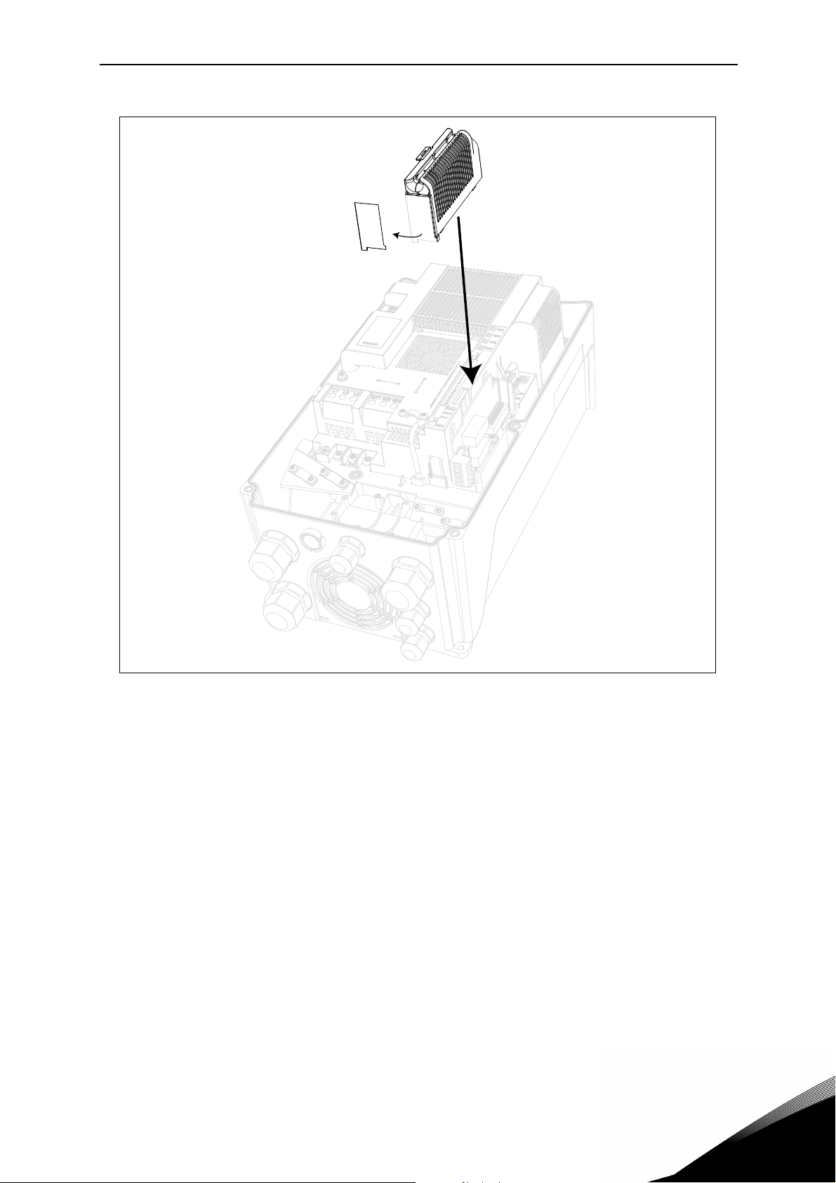
Solar pump Application vacon • 12
Figure 4. Mounting of option slot cover: remove the plastic opening for option board termi-
nals.
Service support: find your nearest Vacon service center at www.vacon.com
2
Page 16

vacon • 13 Solar pump Application
2
Page 17

Description of Groups vacon • 14
3. DESCRIPTION OF GROUPS
3.1 Keypad Reference: Menu REF
This menu is automatically entered when pressing the LOC/REM keypad and shows the frequency reference in Local control mode.
The reference is also active when selected as main reference (P1.12=4) or as secondary reference (P2.15=4).
Value is limited between min frequency P1.1 and max frequency P1.2.
In Local mode, or when keypad is the active control place (P1.11=1 or P2.14=1), direction of rotation is determined with P2.23 or by pressing the left or right arrow button.
Service support: find your nearest Vacon service center at www.vacon.com
3
Page 18
vacon • 15 Description of Groups
3.2 Monitor group: menu MON
VACON® 20 CP/X AC drive provides you with a possibility to monitor the actual values of parameters and signals as well as statuses and measurements. See Table in which the basic
monitoring values are presented.
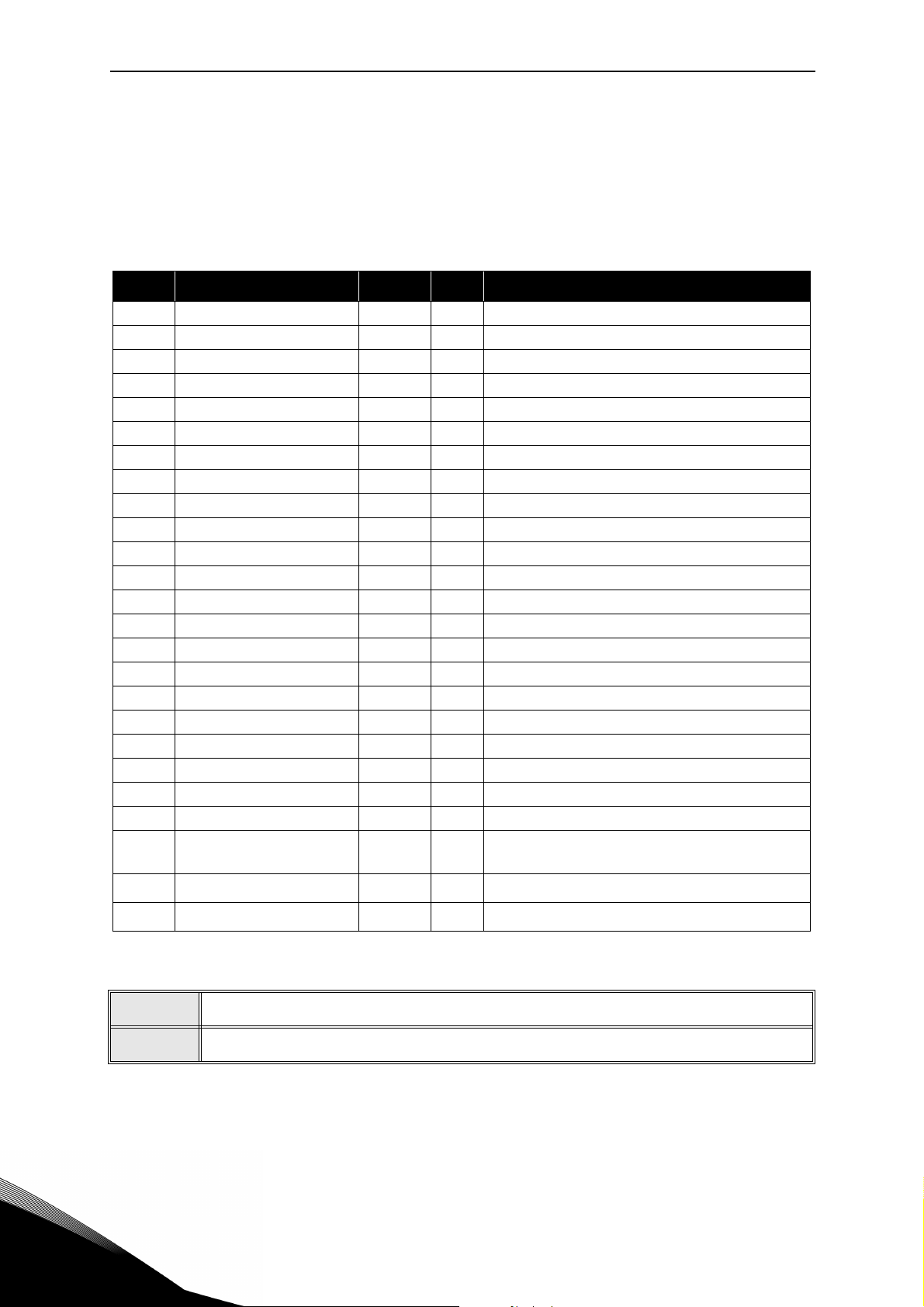
3.2.1 Drive Monitors
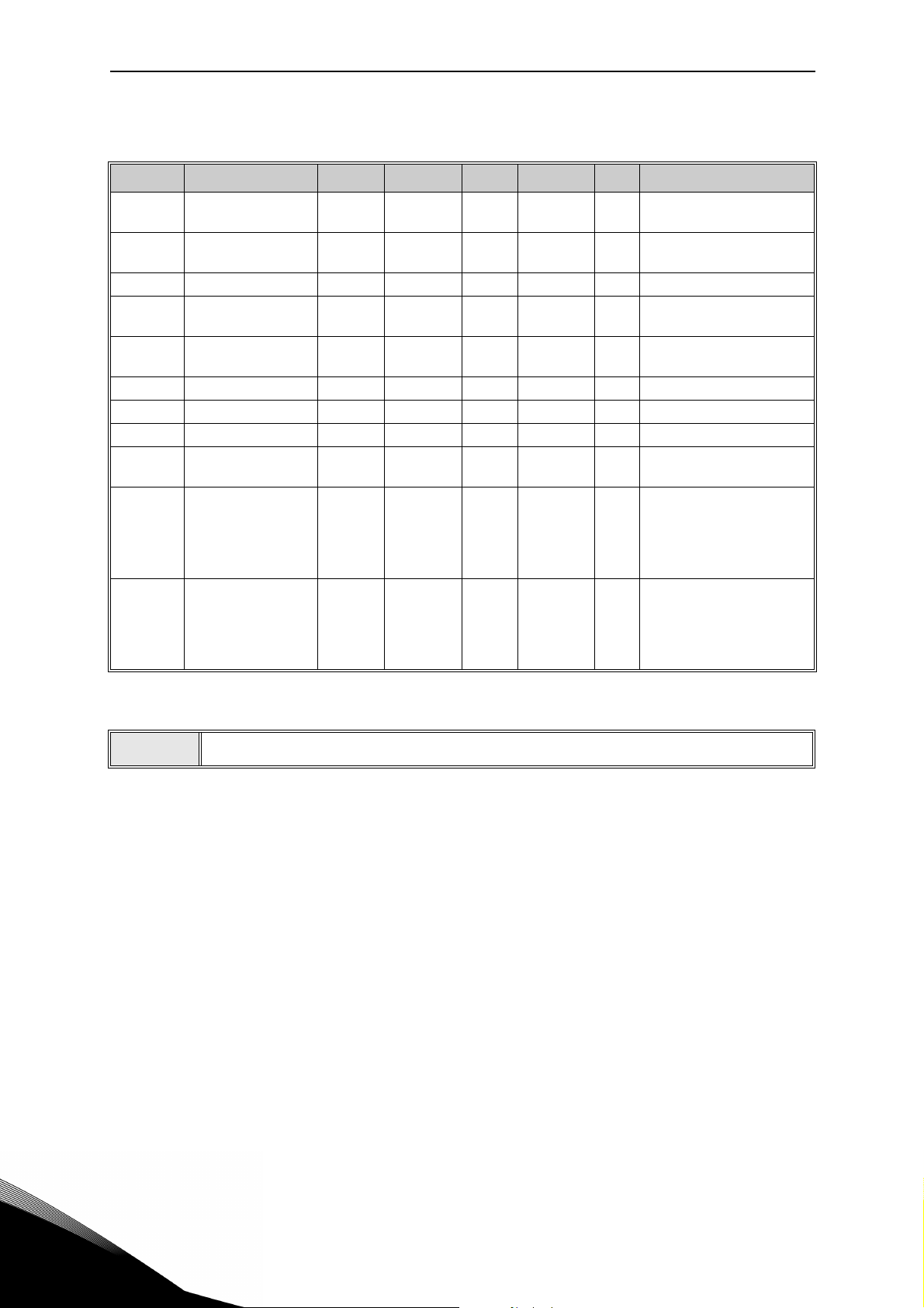
Code Monitoring value Unit ID Description
V1.1 Output frequency Hz 1 Output frequency to motor
V1.2 Frequency reference Hz 25 Frequency reference to motor control
V1.3 Motor shaft speed rpm 2 Motor speed in rpm
V1.4 Motor Current A 3
V1.5 Motor Torque % 4 Calculated shaft torque
V1.6 Motor Power % 5 Total power consumption of AC drive
V1.7 Motor Voltage V 6
V1.8 Motor temperature % 9 Calculated motor temperature
V1.9 DC-link voltage V 7
V1.10 Unit temperature °C 8 Heatsink temperature
V1.11 Board temperature °C 1825 Power board temperature
V1.12 Analogue input 1 % 13 Analogue input AI1
V1.13 Analogue input 2 % 14 Analogue input AI2
V1.14 Analogue output % 26 Analogue output
V1.15 DI1, DI2, DI3 15 Digital inputs status
V1.16 DI4, DI5, DI6 16 Digital inputs status
V1.19 RO1, RO2, DO 17 Digital outputs status
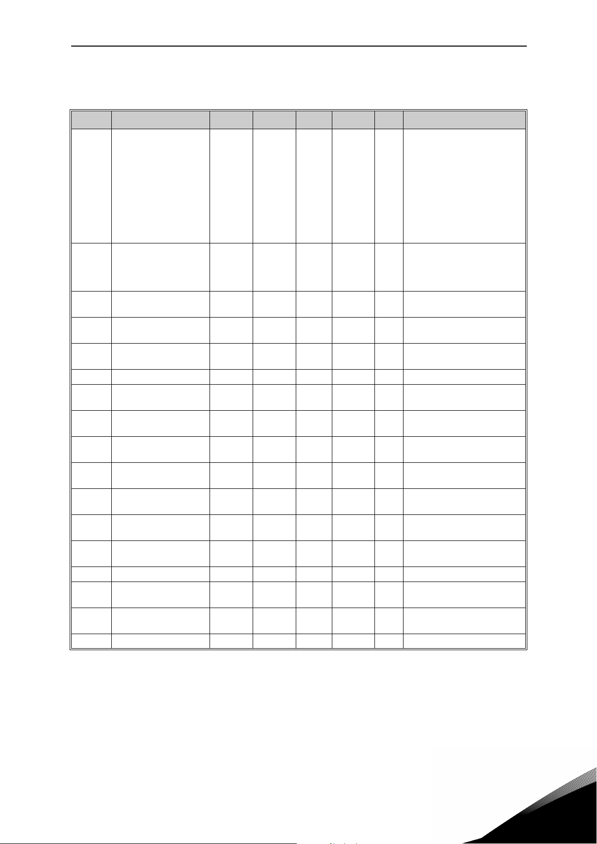
V1.21 Process variable 29 Scaled process variable See P7.10
V1.22 PID setpoint % 20
V1.23 PID feedback % 21
V1.24 PID error value % 22
V1.25 PID output % 23
V1.26 Actual Flow
V1.27 Volume counter 1*
V1.28 Volume counter 2*
litres/
min
3
m
m3x10
1956
1955 Cumulative water volume counter.
4
1962 Cumulative water volume counter.
Actual flow, measured by transducer defined
in P15.1
3
NOTE!
NOTE!
Table 3: Monitor values.
Values V1.22-25 are hidden when PID output is not used as frequency reference.
* The total volume of water in [m3] is given by: V1.27 + (V1.28 x 10000).
Page 19

Description of Groups vacon • 16
3.2.2 Solar Monitors
Code Monitoring value Unit ID Description
V2.1 Vmp Ref V 1934 DC voltage reference for MPP regulation
V2.2 Vmp Ref correct V 1942
V2.3 Power kW 1936 Motor shaft power
V2.4 Energy counter MWh 1935 Counter of energy taken by the supply
Table 4. Solar motor values.
Present correction on DC voltage reference
(P&O + oscillation)
Service support: find your nearest Vacon service center at www.vacon.com
3
Page 20

vacon • 17 Description of Groups
3.3 Parameter Groups: Menu PAR
The Solar Pump Application embodies the following parameter groups:
Menu and Parameter group Description
Group Basic Parameters: Menu PAR G1 Basic settings
Group Advanced Settings: Menu PAR G2 Advanced parameter settings
Group Analogue inputs: Menu PAR G3 Analogue input programming
Group Digital inputs: Menu PAR G4 Digital input programming
Group Digital outputs: Menu PAR G5 Digital output programming
Group Analogue outputs: Menu PAR G6 Analogue outputs programming
Group Supervisions: Menu PAR G7 Prohibit frequencies programming
Group Motor Control: Menu PAR G8 Motor control and U/f parameters
Group Protections: Menu PAR G9 Protections configuration
Group Autoreset: Menu PAR G10 Auto reset after fault configuration
Group Fieldbus: Menu PAR G11 Fieldbus data out parameters
Group PID Control: Menu Par G12 PID controller parameters
Group Solar: Menu PAR G14 Solar specific parameters.
Group Flow meter: Menu PAR G15 Flow meter parameters.
Table 5. Parameter groups
Column explanations:
Code = Location indication on the keypad; Shows the operator the parameter num-
ber.
Parameter= Name of parameter
Min = Minimum value of parameter
Max = Maximum value of parameter
Unit = Unit of parameter value; Given if available
Default = Value preset by factory
ID = ID number of the parameter
Description= Short description of parameter values or its function
= The parameter may be changed only in Stop state
3
Page 21

Description of Groups vacon • 18
3.3.1 Group Basic Parameters: Menu PAR G1
Code Parameter Min Max Unit Default ID Description
P1.1 Min frequency 0.00 P1.2 Hz 20.00 101
P1.2 Max frequency P1.1 320.00 Hz 50.00 102
P1.3 Acceleration time 0.1 3000.0 s 3.0 103
P1.4 Deceleration time 0.1 3000.0 s 3.0 104
P1.5 Current limit
P1.6 Motor nominal voltage 180 500 V 400 110
P1.7
P1.8 Motor nominal speed 24 20000 rpm 1440 112
P1.9 Motor nominal current
P1.10 Motor cos ϕ 0.30 1.00 0.85 120
P1.11 Control Place 0 2 0 125
P1.12
P1.13 Start function 0 1 0 505
P1.14 Stop function 0 2 0 506
Motor nominal
frequency
Frequency reference
source
0.2 x I
8.00 320.00 Hz 50.00 111
0.2 x I
07 01819
2 x I
H
H
H
2 x I
A
A
H
I
H
I
H
Minimum allowed frequency reference
Maximum allowed frequency
reference
Defines the time required
for the output frequency to
increase from zero frequency to maximum frequency
Defines the time required
for the output frequency to
decrease from maximum
frequency to zero frequency
Maximum motor current
107
from AC drive
Find this value U
rating plate of the motor.
This parameter sets the
voltage at the field weakening point to 100% * U
Note also used connection
(Delta/Star).
Find this value f
ing plate of the motor.
Find this value nn on the rating plate of the motor.
Find this value In on the rat-
113
ing plate of the motor.
Find this value on the rating
plate of the motor
Run and direction control:
0 = I/O terminals
1 = Keypad
2 = Fieldbus
Selection of reference
source:
0 = AI1
1 = AI2
2 = PID reference
3 = not used
4 = Keypad
5 = Fieldbus
6 = AI1+AI2
7 = Max Frequency
0=Ramping
1=Flying start
0: coasting
1: ramp to min frequency
2: ramp to zero frequency
on the
n
nMotor
on the rat-
n
.
Table 6. Basic parameters.
Service support: find your nearest Vacon service center at www.vacon.com
3
Page 22

vacon • 19 Description of Groups
P1.15 Torque boost 0 1 0 109
P1.16 Show parameters 0 1 0 115
P1.17 Energy counter reset 0 1 0 1933
P1.18 Volume counters reset 0 1 0 1961
Table 6. Basic parameters.
0 = Not active
1 = Auto torque boost
0 = only Basic
1 = All groups
Value 1 resets energy counter V2.4.
Value 1 resets volume counters V1.27 and V1.28.
3
Page 23
Description of Groups vacon • 20
3.3.2 Group Advanced Settings: Menu PAR G2
Code Parameter Min Max Unit Default ID Description
Logic = 0:
Start sign 1 = Start Forward
Start sign 2 = Start Backward
Logic =1:
Start sign 1 = Start
P2.1 Start/Stop logic 0 4 0 300
P2.2 Preset speed 1 0.00 P1.2 Hz 10.00 105 Multistep speed 1
P2.3 Preset speed 2 0.00 P1.2 Hz 15.00 106 Multistep speed 2
P2.4 Preset speed 3 0.00 P1.2 Hz 20.00 126 Multistep speed 3
P2.9 Start acceleration time 0.1 3000.0 s 1.0 502
P2.14 Control place 2 0 2 0 1806
P2.15
P2.22 Stop button active 0 1 1 114
P2.23 Keypad Reverse 0 1 0 123
Frequency reference
source 2
0 7 1 1820
Start sign 2 = Reverse
Logic = 2:
Double Start
Logic = 3:
Start sign 1 + Analogue sign
Logic = 4:
Solar only
Time from 0 to min frequency
Alternative control place:
0: I/O terminals
1: Keypad
2: Fieldbus
Selection of reference
source:
0 = AI1
1 = AI2
2 = PID reference
3 = not used
4 = Keypad
5 = Fieldbus
6 = AI1+AI2
7 = Max Frequency
0 = Limited function of Stop
button
1 = Stop button always
enabled
Direction of motor rotation
when control place is keypad
0 = Forward
1 = Reverse
Table 7. Advanced settings group.
NOTE!
Service support: find your nearest Vacon service center at www.vacon.com
Visibility of the group depends on P1.16.
P2.18 - P2.21 are available only with Mains connected.
3
Page 24
vacon • 21 Description of Groups
3.3.3 Group Analogue inputs: Menu PAR G3
Code Parameter Min Max Unit Default ID Description
P3.1 AI1 signal range 0 1 0 379
P3.2 AI1 custom min -100.00 100.00 % 0.00 380
P3.3 AI1 custom max -100.00 300.00 % 100.00 381 Custom range max setting
P3.4 AI1 filter time 0.0 10.0 s 0.1 378
P3.5 AI2 signal range 0 1 1 390
P3.6 AI2 custom min -100.00 100.00 % 0.00 391 See P3.2
P3.7 AI2 custom max -100.00 300.00 % 100.00 392 See P3.3
P3.8 AI2 filter time 0.0 10.0 s 0.1 389 See P3.4
P3.9 Star signal select 0 1 0 1810
P3.10 Start level 0.00 100.00 % 10.00 1857
P3.11 Stop Level 0.00 100.00 % 60.00 1856
0 = 0…10V / 0…20mA
1 = 2…10V / 4…20mA
Custom range min setting
20% = 4-20 mA/2-10 V
Filter time for analogue
input 1
0 = 0…10V / 0…20mA
1 = 2…10V / 4…20mA
0 = AI1
1 = AI2
Not scaled analogue signal
If P3.10 < P3.11:
Start below this level
If P3.10> P3.11:
Start above this level
Not scaled analogue signal
If P3.11> P3.10:
Stop above this level
If P3.11 < P3.10:
Stop below this level
NOTE!
Table 9. Analogue inputs group.
Visibility of the group depends on P1.16.
3
Page 25
Description of Groups vacon • 22
3.3.4 Group Digital inputs: Menu PAR G4
Code Parameter Min Max Unit Default ID Description
Start signal 1 when control
place is I/O 1 (FWD)
See P2.1 for function.
0 = not used
P4.1 Start signal 1 0 6* 1 403
P4.2 Start signal 2 0 6* 2 404
P4.3 Reverse 0 6* 0 412
P4.4 External fault close 0 6* 5 405
P4.5 External fault open 0 6* 0 406
P4.6 Fault reset 0 6* 3 414 Resets all active faults
P4.7 Run enable 0 6* 0 407
P4.8 Preset speed B0 0 6* 4 419
P4.9 Preset speed B1 0 6* 0 420
P4.14 Sel. control place 2 0 6* 0 1813
P4.15 Sel. freq. reference 2 0 6* 0 1814
P4.16
P4.17 Mains connected 0 6* 0 1931
P4.18 Energy counter reset 0 6* 0 1932 Reset of Energy counter
P4.19 Flowmeter pulse 0 6* 5 1953
P4.20 Total flow reset 0 6* 6 1957
P4.21 Minimum water level 0 6* 0 1963 Digital input for water level
Sel. PID
setpoint 2
06* 0431
1 = DIN1
2 = DIN2
3 = DIN3
4 = DIN4
5 = DIN5
6 = DIN6
Start signal 2 when control
place is I/O 1 (REV).
See P2.1 for function.
See P4.1 for selections.
Independent from P2.1
See P4.1 for selections
Fault if signal high
See P4.1 for selections
Fault is signal low
See P4.1 for selections
Must be on to set drive in
Ready state
Binary selector for Preset
speeds
Binary selector for Preset
speeds
Activates control place 2
See P4.1 for selections
Activates reference 2
See P4.1 for selections
Activates setpoint 2
See P4.1 for selections
Digital input is high when
mains supply is connected
Digital input for pulse flow
meter (P15.1 = 1)
Digital input for flow counter
reset
Table 10. Digital inputs group.
Service support: find your nearest Vacon service center at www.vacon.com
3
Page 26
vacon • 23 Description of Groups
Selections for minimum
water level logic:
0 = water level is ok when
digital input for Minimum
water level is high
1 = water level is ok when
digital input for Minimum
water level is low
P4.22 Minimum level logic 0 1 0 1965
P4.23 Maximum water level 0 6* 0 1966 Digital input for water level
P4.24 Maximum level logic 0 1 0 1967
The drive trips with F63 (Low
water level) when water level
is not ok. The fault is reset
with autoreset logic of
Underload (see P10.4 - 7)
when level is restored.
Min level signal/fault refers
to level in a well from which
water is taken.
Selections for maximum
water level logic:
0 = water level is ok when
digital input for Maximum
water level is high
1 = water level is ok when
digital input for Maximum
water level is low
The drive trips with F64 (Max
water level) when water level
is not ok. The fault is reset
with autoreset logic of
Underload (see P10.4 - 7)
when level is restored.
Max level signal/fault refers
to level in a possible tank
where pumped water is
stored.
NOTE!
NOTE!
Table 10. Digital inputs group.
(*)The maximum value is higher when an optional board with digital inputs is
installed. Parameter is automatically reset if value is greater than present limit.
Visibility of the group depends on P1.16.
3
Page 27
Description of Groups vacon • 24
3.3.5 Group Digital outputs: Menu PAR G5
Code Parameter Min Max Unit Default ID Description
Function selection for RO1:
0 = Not used
1 = Ready
2 = Run
3 = General fault
4 = General fault inverted
5 = Warning
P5.1 Relay output 1 content 0 13 1 313
P5.2 Relay output 2 content 0 13 2 314 See P5.1
P5.3 Digital output content 0 13 3 312 See P5.1
P5.4 Relay output 1 on delay 0.00 320.00 s 0.00 458 ON delay for relay
P5.5 Relay output 1 off delay 0.00 320.00 s 0.00 459 OFF delay for relay
P5.6 Relay output 1 inversion 0 1 0 1804
P5.7 Relay output 2 on delay 0.00 320.00 s 0.00 460 See P5.4
P5.8 Relay output 2 off delay 0.00 320.00 s 0.00 461 See P5.5
P5.9 Exp. EO1 output content 0 13 0 1826
P5.10 Exp. EO2 output content 0 13 0 1827 See P5.9
P5.11 Exp. EO3 output content 0 13 0 1828 See P5.9
P5.12 Exp. EO4 output content 0 13 0 1872 See P5.9
6 = Reversed
7 = At speed
8 = Output freq. supervision
9 = Output current superv.
10 = Analogue input superv.
11 = Fieldbus 1
12 = Fieldbus 2
13 = Fault/Warning
0 = no inversion
1 = inverted
Parameter visible when a I/
O expansion board is
installed. See P5.1 for
selection
NOTE!
Table 11. Digital outputs group.
Visibility of the group depends on P1.16.
P5.9 is visible when OPTB2,OPTB5, OPTB9 or OPTBF is installed (first relay EO1).
P5.10 is visible when OPTB2 or OPTB5 is installed (second relay EO2).
P5.11 is visible when OPTB5 is installed (third relay EO3).
P5.12 is visible when OPTBF is installed (digital output EO4).
Service support: find your nearest Vacon service center at www.vacon.com
3
Page 28

vacon • 25 Description of Groups
3.3.6 Group Analogue outputs: Menu PAR G6
Code Parameter Min Max Unit Default ID Description
0 = Not used (fixed 100%)
1 = Freq. reference (0-fmax)
2 = Output freq. (0 -fmax)
3 = Motor speed (0 - Speed
P6.1
P6.2
P6.3 Analogue output scale 0,0 1000,0 % 100.0 311 Scaling factor
P6.4
Analogue output
function
Analogue output
minimum
Analogue output filter
time
0 8 2 307
0 1 0 310
0.00 10.00 s 0.10 308
max)
4 = Output current (0-I
5 = Motor torque (0-T
6 = Motor power (0-P
7 = PID output (0-100%)
8 = Filedbus(0-10000)
0 = 0V
1 = 2V
Filtering time of analogue output signal.
0 = No filtering
nMotor
nMotor
nMotor
)
)
)
Table 12. Analogue outputs group.
3
Page 29

Description of Groups vacon • 26
3.3.7 Group Supervisions: Menu PAR G7
Code Parameter Min Max Unit Default ID Description
P7.1
P7.2
P7.3
P7.4 AnalogIn Supv Signal 0 1 0 356
P7.5 AnalogIn Supv ON level 0.00 100.00 % 80.00 357 ON threshold AI supervision
P7.6
P7.10 Process Source Select 0 5 2 1036
P7.11
P7.12 Process Max Value 0.0 3276.7 100.0 1034
Frequency
supervision 1
Frequency supervision
value 1
Current supervision
value
AnalogIn Supv OFF
level
Process Val
Decim Digits
02 0315
0.00 P1.2 Hz 0.00 316
0.00
0.00 100.00 % 40.00 358 OFF threshold AI supervision
03 11035
2 x I
A0.001811
H
0 = not used
1 = Low limit
2 = High limit
Output frequency supervision
threshold value
Current supervision threshold value
0 = AI1
1 = AI2
Selection of variable proportional to process:
0 = PID feedback value
1 = Output frequency
2 = Motor speed
3 = Motor torque
4 = Motor power
5 = Motor current
Decimals on process display
variable
Process display max value (it
depends on P7.11: with zero
decimal digit the max value
is 32767; with 1 decimal digit
the max value is 3276.7)
NOTE!
Table 13. Supervisions group.
Visibility of the G6 and G7 groups depends on P1.16.
Service support: find your nearest Vacon service center at www.vacon.com
3
Page 30

vacon • 27 Description of Groups
3.3.8 Group Motor Control: Menu PAR G8
Code Parameter Min Max Unit Default ID Description
P8.1 Motor control mode(*) 0 1 0 600
P8.2 Field Weakening Point 30.00 320.00 Hz 50.00 602
P8.3
P8.4 U/f ratio selection(*) 0 2 0 108
P8.5
P8.6
P8.7
P8.8 Switching frequency 1.5 16.0 kHz 6.0 601
P8.11 DC braking current
P8.12
P8.13
P8.14
P8.15
P8.16 Motor Identification 0 1 0 631
P8.18
P8.19
Voltage at Field Weak-
ening Point
U/f curve midpoint
frequency(*)
U/f curve midpoint
voltage(*)
Output voltage at zero
frequency (*)
DC braking time at
stop
Frequency to start DC
braking at ramp stop
DC braking time at
start
Motor stator voltage
drop(*)
Disable undervoltage
regulator
Disable switching freq
regulator
10.00 200.00 % 100.00 603
0.00 P8.2 Hz 50.00 604
0.00 P8.3 % 100.00 605
0.00 40.00 % 0.00 606
0.3 x I
0.00 600.00 s 0.00 508
0.10 10.00 Hz 1.50 515
0.00 600.00 s 0.00 516
0.00 100.00 % 0.00 662
0 1 0 1854
0 1 0 1855
2 x I
H
A
H
I
H
0 = Frequency control
1 = Speed control
Field weakening point frequency
Voltage at FWP as % of
Motor nominal voltage
0 = linear
1 = quadratic
2 = programmable
Midpoint frequency for programmable U/f curve
Midpoint voltage for programmable U/f curve
Voltage at 0,00 Hz as % of
Motor nominal voltage
Switching frequency of the
IGBTs
Defines the current
injected into the motor dur-
507
ing DC-braking.
0 = Disabled
Determines if braking is
ON or OFF and the braking
time of the DC-brake when
the motor is stopping.
The output frequency at
which the DC-braking is
applied.
This parameter defines the
time for how long DC current is fed to motor before
acceleration starts.
Voltage drop on the motor
windings as % of Motor
nominal voltage
0 = not active
1 = standstill identification
(to activate, RUN command within 20s)
0 = Enabled
1 = Disabled
0 = Enabled
1 = Disabled
3
NOTE!
NOTE!
Table 14. Motor control group.
(*) Parameter is automatically set by motor identification.
Visibility of the group depends on P1.16.
Page 31

Description of Groups vacon • 28
3.3.9 Group Protections: Menu PAR G9
NOTE!
Parameters of Motor thermal protection (P9.11 to P9.14 and P9.21-P9.22)
The motor thermal protection is to protect the motor from overheating. The drive is capable of
supplying higher than nominal current to the motor. If the load requires this high current there
is a risk that the motor will be thermally overloaded. This is the case especially at low frequencies. At low frequencies the cooling effect of the motor is reduced as well as its capacity. If the
motor is equipped with an external fan the load reduction at low speeds is small.
The motor thermal protection is based on a calculated model and it uses the output current of
the drive to determine the load on the motor.
The motor thermal protection can be adjusted with parameters. The thermal current I
fies the load current above which the motor is overloaded. This current limit is a function of the
output frequency.
The thermal stage of the motor can be monitored on the control keypad display. See chapter 2.
Visibility of the group depends on P1.16.
speci-
T
If you use long motor cables (max. 100m) together with small drives (≤1.5 kW) the
motor current measured by the drive can be much higher than the actual motor
current due to capacitive currents in the motor cable.
Consider this when setting up the motor thermal protection functions.
The calculated model does not protect the motor if the airflow to the motor is
reduced by blocked air intake grill. The model starts from zero if the control board is
powered off.
Parameters of Stall protection (P9.4 to P9.6)
The motor stall protection protects the motor from short time overload situations such as one
caused by a stalled shaft. The reaction time of the stall protection can be set shorter than that
of motor thermal protection. The stall state is defined with two parameters, P9.5 (
and P9.6 (
rent limiter has reduced the output frequency below the P9.6 for the time P9.5 than the set limit
the stall state is true. There is actually no real indication of the shaft rotation. Stall protection
is a type of overcurrent protection.
Stall frequency limit). If the current is as high as the P1.5 (Current Limit) and the cur-
If you use long motor cables (max. 100m) together with small drives (≤1.5 kW) the
motor current measured by the drive can be much higher than the actual motor
current due to capacitive currents in the motor cable.
Consider this when setting up the motor thermal protection functions.
Stall time)
Service support: find your nearest Vacon service center at www.vacon.com
3
Page 32

vacon • 29 Description of Groups
Parameters of Underload protection (P9.7 to P9.10)
The purpose of the motor underload protection is to ensure that there is load on the motor
when the drive is running. If the motor loses its load there might be a problem in the process,
e.g. a broken belt or a dry pump.
Motor underload protection can be adjusted by setting the underload curve with parameters
P9.8 (Underload protection: Field weakening area load) and P9.9 (
frequency load
), see below. The underload curve is a squared curve set between the zero fre-
Underload protection: Zero
quency and the field weakening point. The protection is not active below 5Hz (the underload
time counter is stopped).
The torque values for setting the underload curve are set in percentage which refers to the
nominal torque of the motor. The motor's name plate data, parameter motor nominal current
and the drive's nominal current I
are used to find the scaling ratio for the internal torque val-
L
ue. If other than nominal motor is used with the drive, the accuracy of the torque calculation
decreases.
If you use long motor cables (max. 100m) together with small drives (≤1.5 kW) the
motor current measured by the drive can be much higher than the actual motor
current due to capacitive currents in the motor cable.
Consider this when setting up the motor thermal protection functions.
Code Parameter Min Max Unit Default ID Description
0 = No action
Response to 4mA
P9.1
P9.2
P9.3 Earth fault protection 0 2 2 703
P9.4 Motor stall protection 0 2 1 709 See P9.3
P9.5 Motor stall delay 0.0 300.0 s 5.0 711
P9.6 Motor stall min freq. 0.10 320.00 Hz 15.00 712
P9.7 Underload protection 0 2 2 713
reference fault
(< 4mA)
4mA fault detection
time
04 1700
0.0 10.0 s 0.5 1430 Time limit
1 = Warning
2 = Fault
3 = Warning if Start active
4 = Fault if Start active
0 = No action
1 = Warning
2 = Fault
This is the maximum time
allowed for a stall stage.
For a stall state to occur, the
output frequency must have
remained below this limit for
a certain time.
See P9.3 for the fault
response.
See P9.23 for the underload
mode. When P9.23 = 0,
Underload is determined by
P9.8 - P9.10. When P9.23 =1,
the fault is related to P9.24.
3
Table 15. Protections group.
Page 33

Description of Groups vacon • 30
This parameter gives the
P9.8
P9.9
P9.10 Underload time 1 300 m 20 716
P9.11
P9.12
P9.13
P9.14
P9.15
P9.17 Parameter lock 0 1 0 1805
P9.18
P9.19
P9.20
P9.21
P9.22
P9.23 UnderloadDetectMode 0 1 0 1950
P9.24 Minimum Flow 1 65500
Underload load curve
at nominal freq.
Underload load curve
at min freq.
Thermal protection of
the motor
Motor ambient
temperature
Motor cooling factor at
zero speed
Motor thermal time
constant
Response to fieldbus
fault
Response to STO
disable
Response to input
phase fault
Input phase fault max
ripple
Motor temp initial
mode
Motor temp initial
value
10.0 150.0 % 90.0 714
0.0 150.0 % 0.0 715
0 2 2 704 See P9.3
-20 100 °C 40 705 Ambient temperature in °C
0.0 150.0 % 40.0 706
1 200 min 45 707
0 2 2 733 See P9.3
03 11876
0 2 0 1877 See P9.3
0 75 0 1893
02 01891
0100%331892
litres/
min
300 1951
value for the minimum
torque allowed when the output frequency is above the
field weakening point.
This parameter gives value
for the minimum torque
allowed with zero frequency.
This is the maximum time
allowed for an underload
state to exist.
Defines the cooling factor at
zero speed in relation to the
point where the motor is running at nominal speed without external cooling.
The time constant is the time
within which the calculated
thermal stage has reached
63% of its final value.
Lock parameter editing.
0 = Edit enabled
1 = Edit disabled
0 = No action
1 = Warning
2 = Fault, not stored in history menu
3 = Fault, stored in history
menu
Sensitivity of input phase
fault detector.
0 = internal value
1 = max sensitivity ->
75 = min sensitivity
0 = start from minimum
1 = start from constant value
2 = start from last value
Initial value(P9.21 = 1) or factor for last previous
value(P9.21 = 2)
0 = Motor Torque
1 = Flowmeter (transducer
defined by P15.1)
Value to determine underload fault if P9.23 is 1
Table 15. Protections group.
Service support: find your nearest Vacon service center at www.vacon.com
3
Page 34

vacon • 31 Description of Groups
3.3.10 Group Autoreset: Menu PAR G10
Code Parameter Min Max Unit Default ID Description
P10.1 Automatic fault reset 0 1 0 731
P10.2 Wait time 0.10 10.0 m 1.0 717
P10.3 Automatic reset tries 1 10 5 759
P10.4
P10.5
P10.6
P10.7 Underload Tries T1,T2 1 10 2 1930
Underload reset Time
1
Underload reset Time
2
Underload reset Time
3
0.1 1200.0 m 2.0 1927
0.1 1200.0 m 30.0 1928
0.1 1200.0 m 300.0 1929
Table 16. Autoreset group.
0 = Disabled
1 = Enabled
Wait time before the first
reset is executed.
NOTE: Total number of trials
(irrespective of fault type)
NOTE!
Visibility of the group depends on P1.16.
3
Page 35

Description of Groups vacon • 32
3.3.11 Group Fieldbus: Menu PAR G11
Code Parameter Min Max Unit Default ID Description
Variable mapped on PD1:
0 = Output frequency
1 = Motor speed
2 = Motor current
3 = Motor voltage
4 = Motor torque
5 = Motor power
6 = DC-link voltage
7 = Active fault code
P11.1 FB DataOut 1 Sel 0 17 0 852
P11.2
P11.3
P11.4
P11.5
P11.6
P11.7
P11.8 FB DataOut 8 Sel 0 17 7 859
P11.9 FB Aux CW selection 0 5 0 1821
P11.10
P11.11
P11.12
FB DataOut 2 Sel
FB DataOut 3 Sel
FB DataOut 4 Sel
FB DataOut 5 Sel
FB DataOut 6 Sel
FB DataOut 7 Sel
FB PID setpoint
selection
FB PID actual
selection
FB AnalogueOut cntrl
selection
0 17 1 853
0 17 2 854
0 17 3 855
0 17 4 856
0 17 5 857
0 17 6 858
0 5 1 1822
0 5 2 1823
0 5 3 1824
8 = Analogue AI1
9 = Analogue AI2
10 = Digital inputs state
11 = PID feedback value
12 = PID setpoint
13 = Power kW
14 = Energy
15 = Flow
16 = Volume 1
17 = Volume 2
Variable mapped on PD2. See
P11.1
Variable mapped on PD3. See
P11.1
Variable mapped on PD4. See
P11.1
Variable mapped on PD5. See
P11.1
Variable mapped on PD6. See
P11.1
Variable mapped on PD7. See
P11.1
Variable mapped on PD8. See
P11.1
PDI for Aux CW
0 = Not used
1 = PDI1
2 = PDI2
3 = PDI3
4 = PDI4
5 = PDI5
PDI for PID Setpoint
See P11.9
PDI for PID Feedback
See P11.9
PDI for Analogue Out CTRL
See P11.9
Table 17. Fieldbus group.
NOTE!
Service support: find your nearest Vacon service center at www.vacon.com
Visibility of the group depends on P1.16.
3
Page 36

vacon • 33 Description of Groups
3.3.12 Group PID Control: Menu Par G12
Code Parameter Min Max Unit
P12.1 Setpoint source 0 3 0 332
P12.2 PID setpoint 1 0.0 100.0 % 50.0 167 Fixed setpoint 1
P12.3 PID setpoint 2 0.0 100.0 % 50.0 168 Fixed setpoint 2
P12.4 Feedback source 0 3 0 334
P12.5 Feedback minimum 0.0 50.0 % 0.0 336 Value at minimum signal
P12.6 Feedback maximum 10.0 300.0 % 100.0 337 Value at maximum signal
P12.7 PID controller P gain 0.0 1000.0 % 100.0 118
P12.8 PID controller I-time 0.00 320.00 s 10.00 119
P12.9 PID controller D-time 0.00 10.00 s 0.00 132
P12.10 Error value inversion 0 1 0 340
P12.11 PID error limit 0.0 100.0 % 100.0 1812 Limit on error
P12.12 Sleep frequency 0.00 200.0 Hz 0.00 1016
P12.13 Sleep time delay 0 3600 s 30 1017
P12.14 Wake-up limit 0.0 100.0 % 5.0 1018
P12.15
P12.16 Min feedback level 0.0 100.0 % 50.0 1895
Feedback Superv.
Response
0 2 2 1894
Defau
lt
ID Description
0 = PID setpoint 1/2
1 = AI1
2 = AI2
3 = Fieldbus
0 = AI2
1 = AI1
2 = Fieldbus
3 = AI1- AI2
If the value of the parameter is set
to 100% a change of 10% in the
error value causes the controller
output to change by 10%.
If this parameter is set to 1,00 second a change of 10% in the error
value causes the controller output
to change by 10.00%/s.
If this parameter is set to 1,00 second a change of 10% in the error
value during 1.00 s causes the
controller output to change by
10.00%.
0 = Normal (Feedback < Setpoint > Increase PID output)
1 = Inverted (Feedback < Setpoint -
Decrease PID output
>
Drive goes to sleep mode when the
output frequency stays below this
limit for a time greater than that
defined by parameter P12.13.
The minimum amount of time the
frequency has to remain below the
Sleep level before the drive is
stopped.
Defines the level for the PID feedback value wake-up.
Response to feedback supervision:
0 = No action
1 = Alarm
2 = Fault
Min variation between setpoint
and feedback to activate the Feedback Superv. Response
)
3
Table 18. PID control group.
Page 37

Description of Groups vacon • 34
To activate Feedback Superv.
Response, the variation between
P12.17 Min feedback time 1 300 s 8 1896
P12.18 Max feedback level 100.0 300.0 % 150.0 1897
P12.19 Max feedback time 1 300 s 8 1898
Table 18. PID control group.
setpoint and feedback must have
remained below P12.16 for this
time.
Max variation between setpoint
and feedback to activate the Feedback Superv. Response
To activate Feedback Superv.
Response, the variation between
setpoint and feedback must have
remained above P12.18 for this
time.
NOTE!
This group is hidden when PID output is not used as frequency reference.
Service support: find your nearest Vacon service center at www.vacon.com
3
Page 38

vacon • 35 Description of Groups
3.3.13 Group Solar: Menu PAR G14
Code Parameter Min Max Unit
Defau
lt
ID Description
Start Settings
P14.1 Start DC Voltage 400 800 V 650 1916
P14.2 Short restart delay 0.1 5.0 m 1.0 1917 Delay time to restart
P14.3 Short restart delay tries 1 10 5 1918 Number of restart tries
P14.4 Long restart delay 6.0 30.0 m 10.0 1919 Long delay time to restart
DV voltage threshold level to
activate Run enable
MPPT
P14.5 Vmp at 100% power 400 800 V 600 1920
P14.6 Vmp at 10% power 400 700 V 540 1921
P14.7 Panel/Motor ratio 50.00 100.00 %
P14.8 P gain 0.000 1.000 0.050 1923
P14.9 I gain 0.000 1.000 0.050 1924 Integration time.
P14.10 Acceleration time 0.1 60.0 s 1.0 1925
P14.11 Deceleration time 0.1 60.0 s 1.0 1926
P14.12 P&O update time 2 6 s 3 1939
P14.13 P&O voltage step 3 10 V 5 1940
P14.14 P&O power variation 0.2 5.0 % 1.0 1941
P14.15 P&O local max step 0 60 V 30 1945
P14.16 P&O local max time 1 60 m 10 1946
P14.17 P&O local max freq 0.00 20.00 Hz 10.00 1947
P14.18 Damping sensitivity 5 50 V 10 1943
P14.19 Damping time 3 10 s 4 1944
P14.20 Sleep in solar mode 0 1 0 1964
100.0
0
1922
Gain for internal PI regulator.
The internal frequency reference keeps the panels working
on MPP.
Time from minimum to maximum frequency
Time from maximum to minimum frequency
Amplitude of oscillation to be
recognized
Time for the oscillations on DC
voltage
0 = Sleep disabled
1 = Sleep according to P12.12
and P12.13
3
NOTE!
NOTE!
Table 19. Solar group.
Visibility of the group depends on P1.16.
Sleep in solar mode can be managed according to P12.12 and P12.13
When P14.20 =1, the drive will stop if the output frequency is below the value in
P12.12, for the time in P12.13. It will restart as after a stop due to low power.
Sleep function allows to program a minimum frequency P1.1 that is below the
efficient range of the pump. MPPT can reach this low value, leading to a minimum output power and avoiding to stop the drive in case of temporary reduced
irradiation. If the condition persists, sleep logic will then stop the drive.
Page 39

Description of Groups vacon • 36
3.3.14 Group Flow meter: Menu PAR G15
Code Parameter Min Max Unit Default ID Description
Selections:
0 = not used
P15.1 Flowmeter signal 0 3 0 1958
P15.2 Flow at max anlg signal 0 65500
P14.3 Pulse output volume 0 10000
litres/
min
litres/
pulse
1000 1960
100 1954
Table 20. Flow meter parameters.
1 = Digital pulse
2 = AI1
3 = AI2
Considered when flow meter
signal is from analogue signal
(AI1 or AI2). It is the flow leve at
maximum analogue signal.
Considered when flow meter
signal is from digital input. It is
the total volume of water for
each pulse.
Service support: find your nearest Vacon service center at www.vacon.com
3
Page 40

vacon • 37 Description of Groups
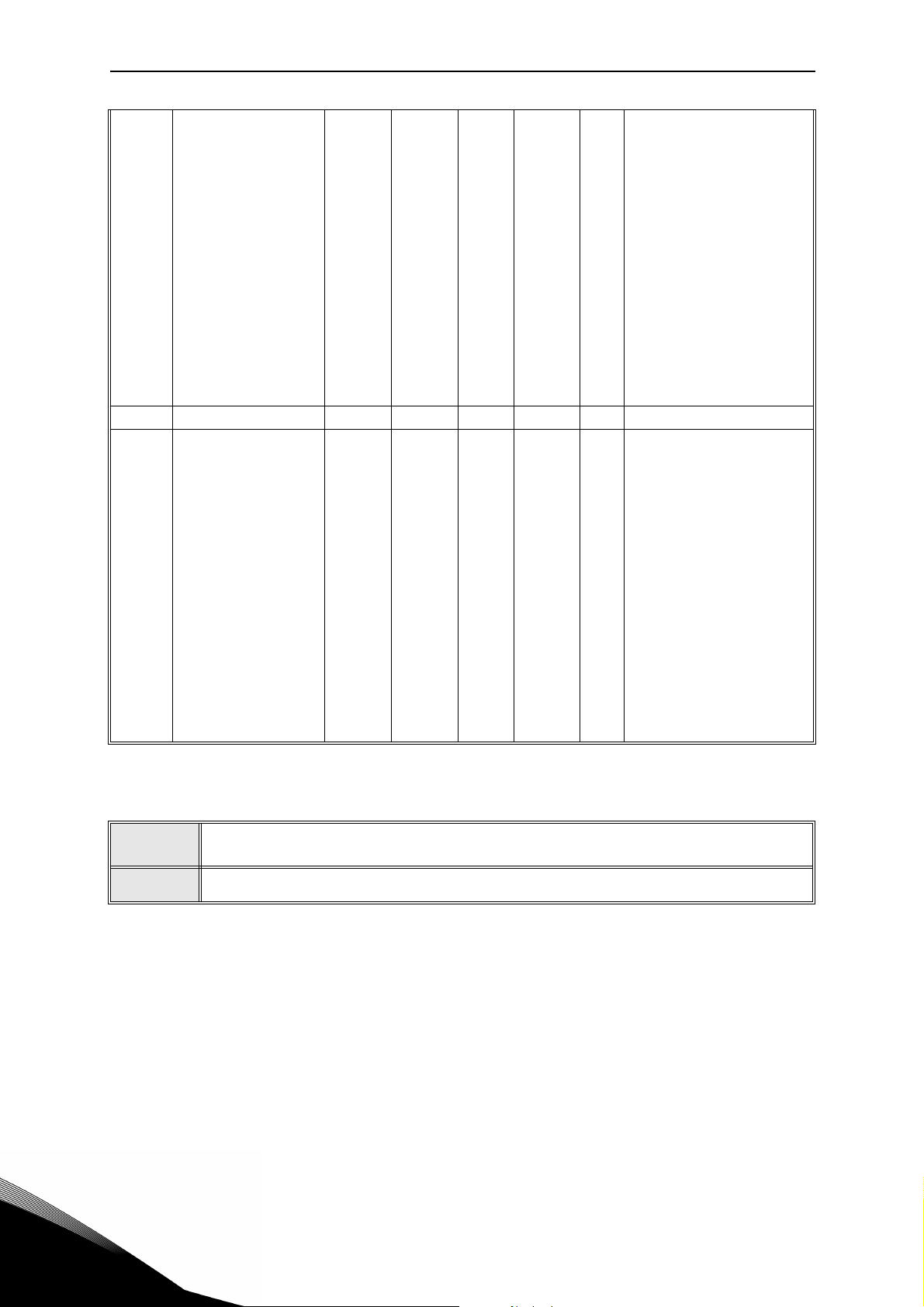
3.4 System parameters, Faults and History faults: Menu FLT
Code Parameter Min Max Unit
V1.1 API system SW ID 2314
V1.2 API system SW version 835
V1.3 Power SW ID 2315
V1.4 Power SW version 834
V1.5 Application ID 837
V1.6 Application Ver. 838
V1.7 System load 839
When no fieldbus board has been installed, the following values are visible:
V2.1 Communication status 808
V2.9 Last communication fault 816
P2.2 FB Protocol Status 0 1 0 809
P2.3 Slave address 1 255 1 810
P2.4 Baud rate 0 8 5 811
P2.6 Parity type 0 2 0 813
Defa
ult
ID Description
Status of Modbus
communication.
Format: xx.yyy
where xx = 0 - 64
(Number of error
messages) yyy = 0 999 (Number of good
messages)
The fault code related to the
last counted bad messages is
shown:
1 = Illegal function
2 = Illegal address
3 = Illegal data value
4 = Illegal slave device
53 = USART receive fault
(parity error/ frame error/
USART buffer overflow)
90 = Receive buffer overflow
100 = Frame CRC Error
101 = Ring buffer overflow
0 = Not used
1 = Modbus used
0 = 300
1 = 600
2 = 1200
3 = 2400
4 = 4800
5 = 9600
6 = 19200
7 = 38400
8 = 57800
Parity type:
0 = None
1 = Even
2 = Odd
Stop bit:
- 2-bits with parity type
“None”;
- 1-bit with parity type “Even”
and “Odd”.
3
Table 21. System parameters, Faults and History faults.
Page 41

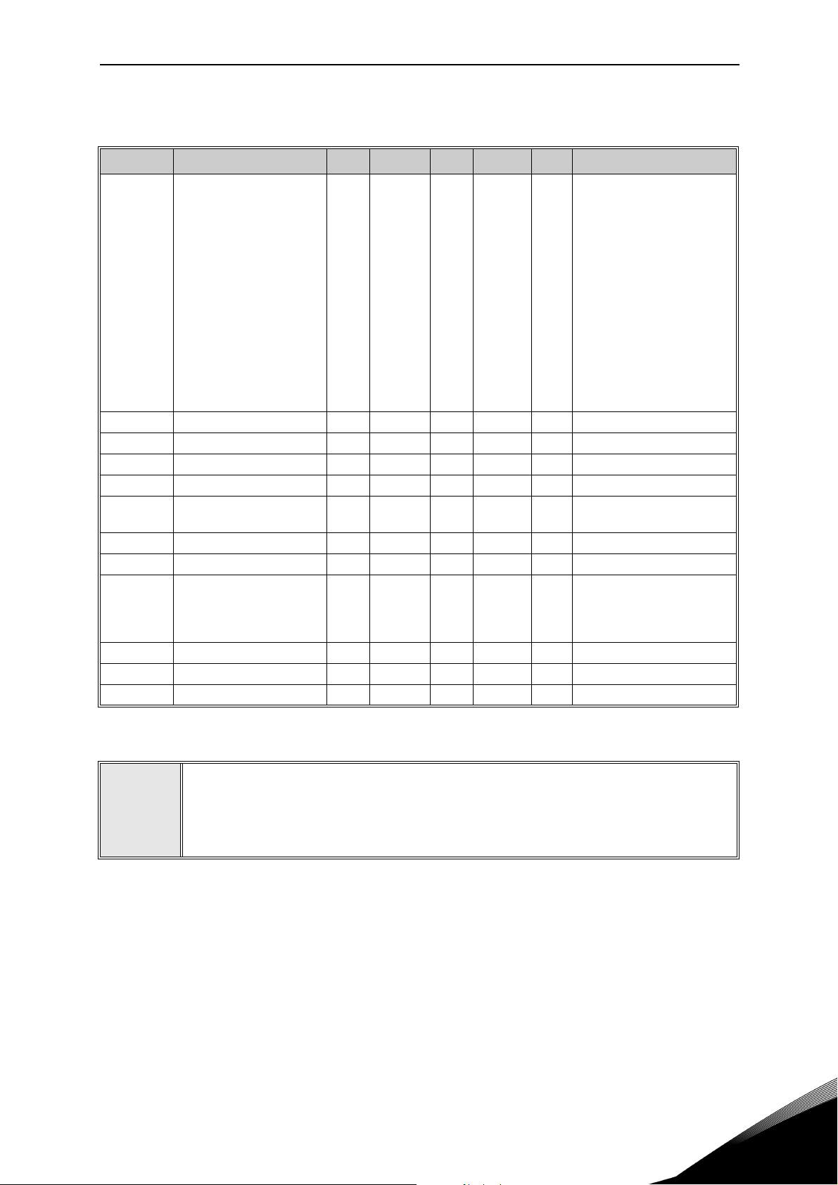
Description of Groups vacon • 38
P2.7 Communication time out 0 255 s 0 814
P2.8 Reset communication status 0 1 0 815
When OPTE6 (CANopen) option board has been installed, the following values are visible:
V2.1
P2.2 CANopen operation mode 1 2 1 14003
P2.3
P2.4 CANopen baud rate 1 8 6 14002
V2.1
P2.2 Output assembly type 20 111 21 14012
P2.3 MAC ID 0 63 63 14010
P2.4 Baud Rate 1 3 1 14011
P2.5 Input assembly type 70 117 71 14013
V2.1
P2.2 Fieldbus protocol 14023
P2.3 Active protocol 14024
P2.4 Active baud rate 14025
P2.5 Telegram type 14027
P2.6 Operate mode 1 3 1 14021
P2.7 Slave address 2 126 126 14020
V2.1 Version number 0
V2.2 Board status 0 Status of OPTEC board
P2.1 Service PIN 0 0 14217
P2.1 Sensor 1 type 0 6 0 14072
P2.2 Sensor 2 type 0 6 0 14073 See P2.1
P2.3 Sensor 3 type 0 6 0 14073 See P2.1
V3.1 MWh counter 827
V3.2 Power on day counter 828
V3.3 Power on hour counter 829
V3.4 RUN day counter 840
V3.5 RUN hour counter 841
CANopen communication
status
CANopen Node ID
When OPTE7 (DeviceNet) option board has been installed, the following values are visible:
DeviceNet communication
status
When OPTE3/E5(Profibus) option board has been installed, the following values are visible:
Profibus communication sta-
tus
When OPTEC (EtherCAT) option board has been installed, the following values are visible:
When OPTC4 (LonWorks) option board has been installed, the following values are visible:
When OPTBH option board has been installed, the following values are visible:
1 127 1 14001
Other information:
14004
14014
14022
Version number of the board
software
Broadcasts a service pin message to the network.
0 = No Sensor
1 = PT100
2 = PT1000
3 = Ni1000
4 = KTY84
5 = 2 x PT100
6 = 3 x PT100
Table 21. System parameters, Faults and History faults.
Service support: find your nearest Vacon service center at www.vacon.com
3
Page 42

vacon • 39 Description of Groups
V3.6 Fault counter 842
V3.7
P4.2 Restore factory defaults 0 1 0 831
P4.3 Password 0 9999
P4.4 Time for keypad backlight 0 99 min 5 833
P4.5 Save parameters to Keypad 0 1 0
P4.6
F5.x Active fault menu 0 9 Hidden when PC is connected
F6.x Fault history menu 0 9 Hidden when PC is connected
Panel parameter set status
monitor
Download parameters from
Keypad
000
0
01 0
Hidden when PC is connected
1 = Restore factory defaults
for all parameters
832
1= Upload all parameters to
Keypad
Hidden when PC is connected.
This function works properly
only with drive supplied.
1= Download all parameters
to Keypad
Hidden when PC is connected.
This function works properly
only with drive supplied.
Table 21. System parameters, Faults and History faults.
3
Page 43

Parameter description vacon • 40
4. PARAMETER DESCRIPTION
Due to its user-friendliness and simplicity of use, the most parameters only require a basic description which is given in the parameter tables in chapter 2.2. In this chapter, you will find additional information on certain more advanced parameters. Should you not find the information
you need contact your distributor.
4.1 Basic Parameters
P1.1 MIN FREQUENCY
Minimum frequency reference.
NOTE: When drive is fed by solar power, if available power is not sufficient to maintain dc voltage above the minimum and frequency above the minimum, the drive will be stopped.
NOTE: if motor current limit is reached, actual output frequency might be lower than this parameter. If this is not acceptable, stall protection should be activated.
P1.2 M
Maximum frequency reference.
P1.3 A
Ramp time, referred to variation from zero frequency to max frequency.
A specific acceleration time from zero to minimum frequency is available (P2.9).
Normal acceleration time (P1.3) is active only in case power is from mains supply.
P1.4 D
Ramp time, referred to variation from max frequency to zero.
Normal deceleration time (P1.4) is active in mains supply and in case the external frequency
reference is lowered below the reference of maximum power. It is also active when start command falls and ramping stop is programmed (stop mode is anyway by coasting, when the output frequency is below minimum).
Specific acceleration and deceleration time are used during power regulation. They are available as parameters in MPPT group, but it is suggested not to change them, unless needed because of stability issues.
P1.5 C
AX FREQUENCY
CCELERATION TIME
ECELERATION TIME
URRENT LIMIT
This parameter determines the maximum motor current from the AC drive. The parameter
value range differs from size to size. When the current limit is active the drive output frequency
is decreased.
NOTE: This is not an overcurrent trip limit.
P1.11 C
Run and direction control. A second control place is programmable in P2.14.
0: I/O terminals
1: Keypad
2: Fieldbus
Service support: find your nearest Vacon service center at www.vacon.com
ONTROL PLACE
4
Page 44

vacon • 41 Parameter description
P1.12 FREQUENCY REFERENCE SOURCE
Defines the source of frequency reference. A second reference source is programmable in
P2.15.
0: Analogue input AI1
1: Analogue input AI2
2: PID reference
3: Not used
4: Keypad
5: Fieldbus
6: AI1 + AI2
7: Max Frequency
External frequency reference is available with the usual logics.
When the drive is fed from solar panels, the external reference is used as the upper limit of the
algorithm searching for maximum power. A low external reference can therefore limit the
power below the maximum available.
Note! the drive will not reach the external reference, if the power from panels is not sufficient.
P1.13 S
0: Ramping
1: Flying start
P1.14 S
Selection
number
0Coasting
1
2
TART FUNCTION
TOP FUNCTION
Selection name Description
The motor is allowed to stop on its own inertia. The control
by the drive is discontinued and the drive current drops to
zero as soon as the stop command is given.
Ramp to min
frequency
Ramp to zero
frequency
After the Stop command, the speed of the motor is decelerated to minimum frequency according to the set deceleration parameters.
After the Stop command, the speed of the motor is decelerated to zero frequency according to the set deceleration
parameters.
4
NOTE: fall of Enable signal, when configured, always determines stop by coasting.
P1.15 T
0: Not used
1: Automatic voltage boost (improves motor torque).
ORQUE BOOST
Page 45

Parameter description vacon • 42
P1.16 SHOW PARAMETERS
0: Only Basic group (and PI Control if function is used)
1: All parameters groups are visible.
P1.17 E
Value 1 resets energy counter.
P1.18 V
Value 1 resets volume counters.
NERGY COUNTER RESET
OLUME COUNTERS RESET
Service support: find your nearest Vacon service center at www.vacon.com
4
Page 46

vacon • 43 Parameter description
4.2 Advanced settings
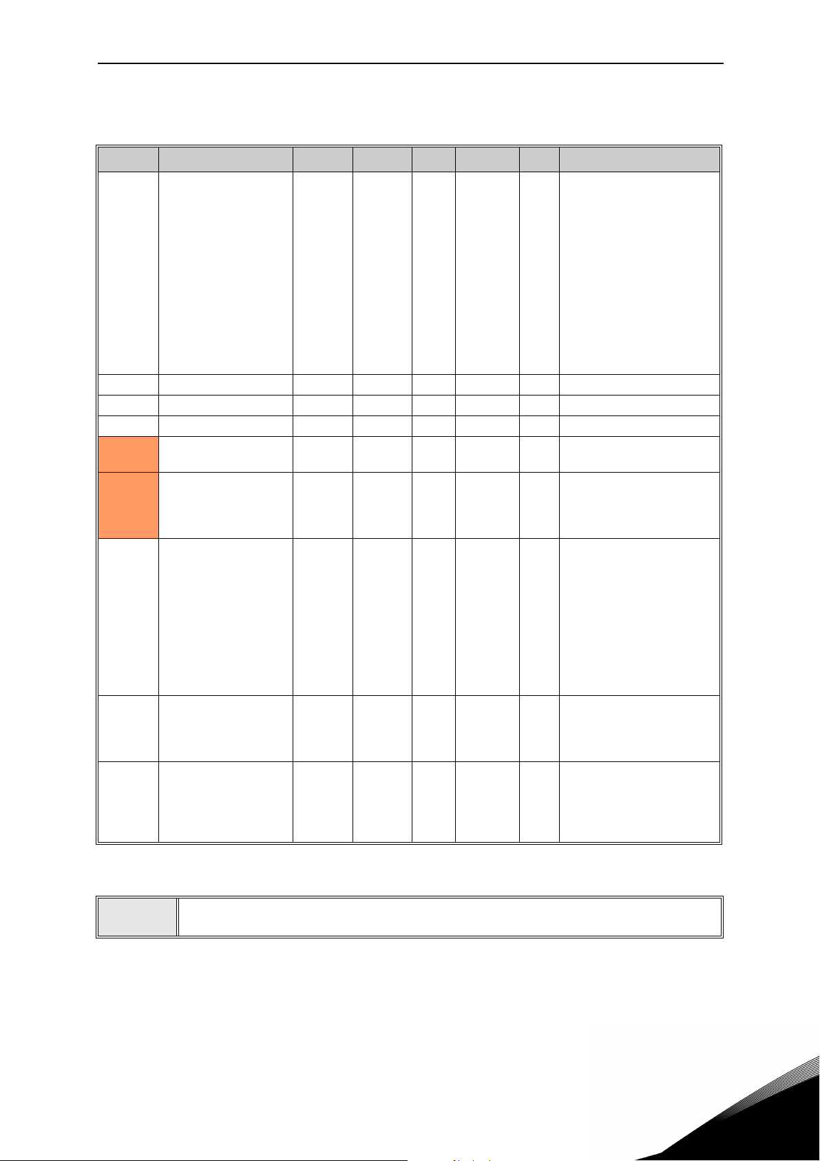
P2.1 START/STOP LOGIC
These logics are based on Start sign 1 and Start sign 2 signals (defined with P4.1 and P4.2).
Usually they are coupled to inputs DIN1 and DIN2.
Values 0...3 offer possibilities to control the starting and stopping of the AC drive with digital
signal connected to digital inputs.
Selection
number
0
1
2 Double Start
3 Start sign 1 + Analogue
4 Solar only
Start sign 1: Start Forward
Start sign 2: Start Backward
Start sign 1: Start Forward
Start sign 2: Reverse
Selection name Note
The function takes place when one contact is
closed. If the other contact is closed while the first
is still closed, the drive will stop and issue alarm
A55
The function takes place when the contacts are
closed.
Run command is set when both Start 1 and Start 2
signals are high. It is reset when both the start signals are low.
This can be used for a simple tank level control
with hysteresis: if the tank has to be filled, two NC
contact sensors will be placed at minimum and
maximum levels. The drive will start below the
minimum and stop above the maximum.
If the tank has to be emptied, two NO contact sensors have to be used. The drive will start above the
maximum and stop below the minimum.
Run command is set when Start 1 signal is high
and a selectable analogue input is below (or above)
a programmable threshold.
This can be used for a tank level control, where the
analogue measurement is used for both starting
the pump and controlling the speed.
Run command is always active. Actual running
condition is determined by DC voltage level available from the solar array.
4
The used stop mode is
pages.
Coasting in all examples. See mode 0 and 1 examples in the following
Page 47

Parameter description vacon • 44
t
Output
frequency
FWD
REV
Start sgn 2
Start sgn 1
Run enable
Set frequency
Set frequency
0 Hz
Keypad Stop
button
Keypad Start
button
1 2 3 4 5 6 7 8 9 10 11 12 13
Selection
number
0
Selection name Note
Start sign 1: Start Forward
Start sign 2: Start Backward
The function takes place when the contacts are
closed.
Explanations:
1
2
3
4
5
6
7
Figure 5. Start/Stop logic = 0.
Start sign 1 activates causing the output frequency to rise. The motor runs forward.
Start sign 2 activates causing the motor drops to
0. Warning 55 appears on the keypad.
Start sign 1 is inactivated which causes the
direction to start changing (FWD to REV)
because Start sign 2 is still active.
Start sign 2 inactivates and the frequency fed to
the motor drops to 0.
Start sign 2 activates again causing the motor to
accelerate (REV) towards the set frequency.
Start sign 2 inactivates and the frequency fed to
the motor drops to 0.
Start sign 1 activates and the motor accelerates
(FWD) towards the set frequency
Run enable signal is set to FALSE, which drops
8
the frequency to 0. The run enable signal is configured with parameter P4.7.
Run enable signal is set to TRUE, which causes
9
the frequency to rise towards the set frequency
because Start sign 1 is still active.
Keypad stop button is pressed and the frequency
10
fed to the motor drops to 0. (This signal only
works if P2.22 Keypad stop button = 1)
Pushing the Start button on the keypad has no
11
effect on the drive status.
The keypad stop button is pushed again to stop
12
the drive.
The attempt to start the drive through pushing
13
the Start button is not successful even if Start
sign 1 is inactive.
Service support: find your nearest Vacon service center at www.vacon.com
4
Page 48

vacon • 45 Parameter description
t
Output
frequency
FWD
REV
Start sgn 2
Start sgn 1
Run enable
Set frequency
Set frequency
0 Hz
Keypad stop
button
Keypad start
button
1 2 3 4 6 7 8 9 10 11 12
5
Selection
number
1
Selection name Note
Start sign 1: Start Forward
Start sign 2: Reverse
The function takes place when the contacts are
closed.
Explanations:
1
2
3
4
5
6
Figure 6. Start/Stop logic = 1.
Start sign 1 activates causing the output frequency to rise. The motor runs forward.
Start sign 2 activates which causes the direction
to start changing (FWD to REV).
Start sign 2 is inactivated which causes the
direction to start changing (REV to FWD)
because Start sign 1 is still active.
Also Start sign 1 inactivates and the frequency
drops to 0.
Despite the activation of Start sign 2, the motor
does not start because Start sign 1 is inactive.
Start sign 1 activates causing the output frequency to rise again. The motor runs forward
because Start sign 2 is inactive.
Run enable signal is set to FALSE, which drops
7
the frequency to 0. The run enable signal is configured with parameter P4.7.
Run enable signal is set to TRUE, which causes
8
the frequency to rise towards the set frequency
because Start sign 1 is still active.
Keypad stop button is pressed and the frequency
9
fed to the motor drops to 0. (This signal only
works if P2.22 Keypad stop button = Yes)
Pushing the Start button on the keypad has no
10
effect on the drive status.
The drive is stopped again with the stop button
11
on the keypad.
The attempt to start the drive through pushing
12
the Start button is not successful even if Start
sign 1 is inactive.
4
Page 49

Parameter description vacon • 46
P2.2 TO
P2.4 PRESET SPEED 1 TO 3
You can use the preset speed parameters to define certain frequency references in advance.
These references are then applied by activating/inactivating digital inputs connected to parameters P4.8 and P4.9 (binary code). The values of the preset speeds are automatically limited between the minimum and maximum frequencies.
Required action Activated frequency
B1 B0 Preset speed 1
B1 B0 Preset speed 2
B1 B0 Preset speed 3
Table 22. Selection of preset frequencies; = input activated
P2.9 S
A specific acceleration time from zero to minimum frequency is available (P2.9). Normal acceleration time (P1.3) is active only in case power is from mains supply. Normal deceleration
time (P1.4) is active in mains supply and in case the external frequency reference is lowered
below the reference of maximum power. It is also active when start command falls and ramping stop is programmed (stop mode is anyway by coasting, when the output frequency is below
minimum).
Specific acceleration and deceleration time are used when power is from solar panels. They
are available as parameters in MPPT group, but it is suggested not to change them, unless
needed because of stability issues.
P2.14 C
Alternative Run and direction control. Activated by digital input defined in P4.14.
0: I/O terminals
1: Keypad
2: Fieldbus
P2.15 F
Alternative source of frequency reference. Activated by digital input defined in P4.15 or fieldbus.
TART ACCELERATION TIME
ONTROL PLACE 2
REQUENCY REFERENCE SOURCE 2
0: Analogue input AI1
1: Analogue input AI2
2: PID reference
3: Not used
4: Keypad
5: Fieldbus
6: AI1+AI2
7: Max Frequency
Service support: find your nearest Vacon service center at www.vacon.com
4
Page 50

vacon • 47 Parameter description
P2.22 STOP BUTTON ACTIVE
0: Active only in keypad control mode
1: Always active
P2.23 K
Effective when control is from keypad
0: Forward
1: Backward
EYPAD REVERSE
4
Page 51

Parameter description vacon • 48
%
100%
63%
P3.2
t
Filtered signal
Unfiltered signal
4.3 Analogue inputs
P3.1 AI1 SIGNAL RANGE
P3.5 AI2 SIGNAL RANGE
Range of the electrical signal.
0: 0-100%: 0…10V or 0… 20mA
1: 20-100%: 2…10V or 4… 20mA
P3.4 AI1
P3.8 AI2 FILTER TIME
Low pass filter time constant, to reduce noise. When this parameter is given a value greater
than 0 the function that filters out disturbances from the incoming analogue signal is activated.
NOTE: Long filtering time makes the regulation response slower!
FILTER TIME
Figure 7.AI1 signal filtering.
P3.2 AI1 CUSTOM MIN
P3.6 AI2 CUSTOM MIN
Customized value for minimum signal. Effective when different than 0%
P3.3 AI1
P3.7 AI2 CUSTOM MAX
Customized value for maximum signal. Effective when different than 100%.
Service support: find your nearest Vacon service center at www.vacon.com
CUSTOM MAX
4
Page 52

vacon • 49 Parameter description
0100
Max Freq.
-100 20050
Min Freq.
Analogue input AI [%]
Frequency Reference
Example of custom range use with analogue input:
Figure 8.
Description of Figure 8.
Custom min and Custom max parameters configure the input range for analog input that will
affect Frequency reference.
Blue line shows an example with Custom Min = -100% and Custom Max = 100%. This settings
provides a frequency range between (Maximum frequency - Minimum frequency)/2 and Maximum frequency. With minimum analogue signal the Frequency reference is at 50% of the set
frequency range (Max frequency - Min frequency)/2. With maximum analogue signal the Frequency reference is at Maximum frequency.
Green line shows the default settings of custom values: Custom Min =0% and Custom Max =
100%. This settings provides a frequency range between Minimum and Maximum frequency.
With minimum analogue signal the Frequency reference is at Minimum frequency while with
the maximum level is at Maximum frequency.
Orange line shows an example with Custom min = 50% and Custom Max = 100%. These settings
provides a frequency range between Minimum and Maximum frequency. The Frequency reference changes linearly within the frequency range with the analogue signal between 50% and
100% of its range.
4
Page 53

Parameter description vacon • 50
0 100
Max Freq.
-100 20050
Min Freq.
Analogue input AI [%]
Frequency Reference
Figure 9.
Description of Figure 9:
Green line shows an example with Custom Min = 100% and Custom Max = -100%. This settings
provides a frequency range between Minimum frequency and (Maximum frequency - Minimum
frequency)/2. With minimum analogue signal the Frequency reference is at 50% of the set frequency range (Max frequency - Min frequency)/2, and with maximum analogue signal the Frequency reference is at Minimum frequency.
Blue line shows the inversion of the default settings of custom values: Custom Min =100% and
Custom Max = 0%. This settings provides a frequency range between the Minimum frequency
and the Maximum frequency. With minimum analogue signal the Frequency reference is Maximum frequency while with the maximum level is Minimum frequency.
Orange line shows an example with Custom min = -100% and Custom Max = 0%. This settings
provides a frequency range between Minimum and Maximum frequency. The frequency reference is always at its minimum value (Minimum frequency) within the analogue signal range.
Service support: find your nearest Vacon service center at www.vacon.com
4
Page 54

vacon • 51 Parameter description
0100
Max Freq.
-100 20050
Min Freq
Analogue input AI [%]
Frequency Reference
Figure 10.
Description of the Figure 10:
Blue line shows an example with Custom Min = 0% and Custom Max = 200%. This settings provides a frequency range between Minimum frequency and (Maximum frequency - Minimum
frequency)/2. With minimum analogue signal the Frequency reference is at minimum value of
the set frequency range (Minimum frequency), and with maximum analogue signal the Frequency reference is at (Maximum frequency - Minimum frequency)/2.
Green line shows an example with Custom Min =100% and Custom Max = 200%. This settings
provides a frequency range always at Minimum frequency. The Frequency reference is at Minimum frequency within the entire analogue signal range.
Orange line shows an example with Custom min = 0% and Custom Max = 50%. This settings
provides a frequency range between Minimum and Maximum frequency. The Frequency reference changes linearly within the frequency range with the analogue signal between the 0% and
50% of its range. With the analogue signal between 50% and 100% of its range, the Frequency
reference is always at its maximum value (Maximum frequency).
4
Page 55

Parameter description vacon • 52
P3.9 START SIGNAL SELECT
Run command is set when Start 1 signal is high and a selectable analogue input is below (or
above) a programmable threshold.
This can be used for a tank level control, where the analogue measurement is used for both
starting the pump and controlling the speed.
P3.10 S
Unscaled analogue signal
If P3.10 < P3.11:
Start below this level
If P3.10> P3.11:
Start above this level
P3.11 S
Unscaled analogue signal
If P3.11> P3.10:
Stop above this level
If P3.11 < P3.10:
Stop below this level
TART LEVEL
TOP LEVEL
Service support: find your nearest Vacon service center at www.vacon.com
4
Page 56

vacon • 53 Parameter description
4.4 Digital inputs
P4.1 START SIGNAL 1
P4.2 S
TART SIGNAL 2
Signals for start and direction. Logic is selected with P2.1.
P4.3 R
EVERSE
Should be used when Start signal 2 has not the meaning of reverse.
P4.4 E
XTERNAL FAULT CLOSE
Fault is triggered by high digital input.
P4.5 E
XTERNAL FAULT OPEN
Fault is triggered by low digital input.
P4.6 F
AULT RESET
Active on rising edge.
P4.7 R
UN ENABLE
Motor stops by coasting if the signal is missing.
Note: The drive is not in Ready state when Enable is low.
P4.8 P
P4.9 P
RESET SPEED B0
RESET SPEED B1
Digital inputs for preset speed selection, with binary coding.
P4.14 S
EL. CONTROL PLACE 2
Digital input high activates control place 2 (P2.14).
P4.15 S
EL. FREQ. REFERENCE 2
Digital input high activates frequency reference source 2 (P2.15).
P4.16 S
EL. PID SETPOINT 2
Digital input high activates setpoint 2 (P12.3), when P12.1=0.
P4.17 M
AINS CONNECTED
In case the drive is fed by mains supply, the controller knows this situation through a specific
digital input.
The functions related to DC voltage (start enable, MPPT) are disabled in this condition.
4
P4.18 E
NERGY COUNTER RESET
This parameter enables reset of Energy counter.
Page 57

Parameter description vacon • 54
P4.19 FLOWMETER PULSE
Digital input for pulse flow meter (P15.1 = 1).
P4.20 F
LOW COUNTER RESET
Digital input for flow counter reset.
P4.21 M
INIMUM WATER LEVEL
Digital input for minimum water level.
P4.22 M
INIMUM LEVEL LOGIC
This parameter selects the logic to check the status of water level due by the digital input set
by P4.21. Selections:
0 = the water level is ok when digital input set by P4.21 is high
1= the water level is ok when digital input set by P4.21 is low
The drive trips with F63 fault (Low water level) when level is not ok. The fault is automatically
reset with the Underload logic (see P10.4-7), when the level is restored.
Min level signal/fault refers to level in a well from which water is taken.
P4.23 M
AXIMUM WATER LEVEL
Digital input for maximum water level.
P4.24 M
AXIMUM LEVEL LOGIC
This parameter selects the logic to check the status of water level due by the digital input set
by P4.23. Selections:
0 = the water level is ok when digital input set by P4.23 is high
1= the water level is ok when digital input set by P4.23 is low
The drive trips with F64 fault (Max water level) when level is not ok. The fault is automatically
reset with the Underload logic (see P10.4-7), when the level is restored.
Max level signal/fault refers to level in a possible tank where pumped water is stored.
Service support: find your nearest Vacon service center at www.vacon.com
4
Page 58

vacon • 55 Parameter description
4.5 Digital outputs
P5.1 RELAY OUTPUT 1 CONTENT
P5.2 RELAY OUTPUT 2 CONTENT
P5.3 DIGITAL OUTPUT CONTENT
Function for relays and digital output.
Selection Selection name Description
0 Not used
1 Ready The frequency converter is ready to operate
2 Run The frequency converter operates (motor is running)
3 General fault A fault trip has occurred
4 General fault inverted A fault trip has not occurred
5 General alarm
6 Reversed The reverse command has been selected
7 At speed The output frequency has reached the set reference
8 Frequency supervision
9 Current supervision
10
11 Fieldbus bit 1 Bit from fieldbus Aux Control word
12 Fieldbus bit 2 Bit from fieldbus Aux Control word
13 Fault/Warning
Analogue inputs supervision
Output frequency is over/under the limit set with
parameters P5.9 and P5.10
Motor current is over the limit set with parameter
P5.11
Analogue inputs selected with parameter P5.12 is
over/under the limits set in P5.13 and P5.14
Table 23. Functions for digital relays.
P5.4 R
P5.5 RELAY OUTPUT 1 OFF DELAY
Possible delays for ON/OFF transitions.
P5.6 R
Inversion of relay state.
P5.7 R
P5.8 RELAY OUTPUT 2 OFF DELAY
Possible delays for ON/OFF transitions.
ELAY OUTPUT 1 ON DELAY
ELAY OUTPUT 1 INVERSION
ELAY OUTPUT 2 ON DELAY
4
Page 59

Parameter description vacon • 56
P5.9 TO
P5.12 EXPANSION EO1, EO2, EO3, EO4 OUTPUT CONTENT
These parameters are visible only when an expansion board with outputs is installed (to see
table below). Relays are available on boards OPT-B2, B5, B9 and BF.
Digital outputs are available on board OPTB1, if no more than 3 terminals are used as inputs,
and on OPTBF.
P5.12 is visible only when expansion board OPTBF is installed.
OPTB1 OPTB2 OPTB5 OPTB9 OPTBF
visible if P2.24 < 4
P5.9 EO1
P5.10 EO2
P5.11 EO3
P5.12 EO4 - - - -
digital out terminal 5
visible if P2.24 < 5
digital out terminal 6
visible if P2.24 < 6
digital out terminal 7
Table 24. Digital outputs available with OPTB-boards
visible
relay terminals 21-22-23
visible
relay terminals 25-26
-
visible
relay terminals 22-23
visible
relay terminals 25-26
visible
relay terminals 28-29
visible
relay terminals 7-8
--
--
visible
relay terminals 22-23
visible
digital out
terminal 3
Service support: find your nearest Vacon service center at www.vacon.com
4
Page 60

vacon • 57 Parameter description
4.6 Analogue Output
P6.1 ANALOGUE OUTPUT FUNCTION
Signal coupled to analogue output.
Selection Selection name Value corresponding to maximum output
0 Not used output always fixed at 100%
1 Frequency reference Max frequency(P1.2)
2 Output frequency Max frequency(P1.2)
3 Motor speed Motor nominal speed
4 Motor current Motor nominal current
5 Motor torque Motor nominal torque (absolute value)
6 Motor power Motor nominal power (absolute value)
7 PID output 100%
8 Fieldbus control 10000
Table 25. Analogue output signals.
P6.2 A
0: 0V
1: 2V
P6.3 A
Scaling factor.
P6.4 A
Time constant of low pass filter.
NALOGUE OUTPUT MINIMUM
NALOGUE OUTPUT SCALE
NALOGUE OUTPUT FILTER TIME
4
Page 61

Parameter description vacon • 58
4.7 Supervisions
P7.1 FREQUENCY SUPERVISION 1
0:No supervision
1:Low limit
2: High limit
P7.2 F
REQUENCY SUPERVISION VALUE 1
Threshold value for frequency supervision.
P7.3 C
URRENT SUPERVISION VALUE
Threshold value for current supervision.
P7.4 A
NALOGIN SUPV SIGNAL
0:AI1
1:AI2
P7.5 A
NALOGIN SUPV ON LEVEL
Output goes high when AI is higher than this value.
P7.6 A
NALOGIN SUPV OFF LEVEL
Output goes low when AI is lower than this value.
P7.10 P
ROCESS SOURCE SELECT
Monitor V1.24 can show a process value, proportional to a variable measured by the drive.
Source variables are:
0: PID actual value (max: 100%)
1: output frequency (max: Fmax)
2: motor speed (max: Speed at Fmax)
3: motor torque (max: Tnom)
4: motor power (max: Pnom)
5: motor current (max: Inom)
P7.11 P
ROCESS VAL DECIM DIGITS
Number of decimals shown on monitor V1.24 and also on parameter P7.12.
P7.12 P
ROCESS MAX VALUE
Value shown on V1.24 when source variable is at its maximum. Proportionality is kept if the
source overtakes the maximum.
Service support: find your nearest Vacon service center at www.vacon.com
4
Page 62

vacon • 59 Parameter description
4.8 Motor control
P8.1 MOTOR CONTROL MODE
0: Frequency control
1: Speed control (sensorless control)
In speed control, the motor slip is compensated.
Note: motor identification automatically sets this parameter to 1.
P8.2 F
Output frequency corresponding to max voltage.
Note: if P1.7 Nominal Frequency is changed, P8.2 will be set at same value.
P8.3 V
Motor voltage when frequency is above FWP, defined as% of nominal voltage.
Note: if P1.6 Nominal Voltage is changed, P8.3 will be set at 100%.
If the programmed maximum frequency is higher than motor nominal frequency, field weakening point is automatically set at maximum frequency and fwp voltage is set proportionally
higher than 100%.
This could allow to exploit the higher voltage possibly coming from the panels.
In this situation the current limit has to be set properly, to prevent a motor overload.
If the drive is fed from mains, maximum output frequency will be limited by actual DC voltage,
according to nominal U/f ratio.
IELD WEAKENING POINT
OLTAGE AT FIELD WEAKENING POINT
4
Page 63

Parameter description vacon • 60
U[V]
f[Hz]
Default: Nominal
voltage of the motor
Linear
Squared
Field
weakening
point
Default:
Nominal frequency
of the motor
P8.4 U/F RATIO SELECTION
0: linear
The voltage of the motor changes linearly as a function of output frequency from zero frequency voltage P8.7 to the field weakening point (FWP) voltage P8.3 at FWP frequency P8.2 This default setting should be used if there is no special need for another setting.
1: quadratic
(from voltage P8.7 at 0Hz, to voltage P8.3 at P8.2 frequency)
The voltage of the motor changes from zero point voltage P8.7 following a squared curve form
from zero to the field weakening point P8.3. The motor runs under-magnetized below the field
weakening point and produces less torque. Squared U/f ratio can be used in applications where
torque demand is proportional to the square of the speed, e.g. in centrifugal fans and pumps.
2: programmable
The U/f curve can be programmed with three different points: Zero frequency voltage P8.7 (P1),
Midpoint voltage/frequencyP8.6/P8.5 (P2) and Field weakening point P8.2/P8.3 (P3).
Programmable U/f curve can be used if more torque is needed at low frequencies. The optimal
settings can automatically be achieved with Motor identification run.
Note: motor identification automatically sets this parameter to 2.
Figure 11. Linear and quadratic curve of the motor voltage.
Service support: find your nearest Vacon service center at www.vacon.com
4
Page 64

vacon • 61 Parameter description
U[V]
f[Hz]
P2
P3
P1
Default: Nominal
voltage of the motor
Linear
Field
weakening
point
Default:
Nominal frequency
of the motor
P8.5 U/F CURVE MIDPOINT FREQUENCY
Enabled if P8.4= 2.
Note: motor identification automatically sets this parameter.
P8.6 U/
Enabled if P8.4= 2.
Note: motor identification automatically sets this parameter.
P8.7 O
Motor voltage at frequency zero.
Note: motor identification automatically sets this parameter.
P8.8 S
PWM frequency. Values above default can cause thermal overload of the drive. Motor noise can
be minimized using a high switching frequency. Increasing the switching frequency reduces
the capacity of the drive. It is recommended to use a lower frequency when the motor cable is
long in order to minimize capacitive currents in the cable.
Figure 12. Programmable curve.
F CURVE MIDPOINT VOLTAGE
UTPUT VOLTAGE AT ZERO FREQUENCY
WITCHING FREQUENCY
4
P8.11 DC
DC current injected at start or stop.
BRAKING CURRENT
Page 65

Parameter description vacon • 62
P8.12 DC BRAKING TIME AT STOP
Time for DC current injection at stop.
P8.13 F
REQUENCY TO START DC BRAKING IN RAMP STOP
DC current injection starts below this frequency.
P8.14 DC
BRAKING TIME AT START
Time for DC current injection at start.
P8.15 M
OTOR STATOR VOLTAGE DROP
Voltage drop on stator windings, at motor nominal current, defined as% of nominal voltage.
Value affects motor torque estimation, slip compensation and voltage boost.
Note: it is suggested not to program manually the value, but to perform motor identification
procedure that automatically sets the value.
P8.16 M
OTOR IDENTIFICATION
This procedure measures motor stator resistance and automatically sets U/f characteristic, to
obtain good torque also at low speed.
0 = not active
1 = standstill identification
Run command must be given and hold high within 20s after programming the value 1. The motor does not rotate and the drive will automatically exit run state at the end of the measurements.
Note: the drive exits run state only, if the measured current exceeds 55% of the motor nominal
current. Procedure sets the following parameters: P8.4, P8.5, P8.6, P8.7, P8.15.
Note: optimized U/f settings will increase motor no load current to a value close to nominal in
the low speed range. External cooling of the motor is needed if the motor works in this condition for significant time.
P8.18 D
ISABLE UNDERVOLTAGE REGULATOR
Undervoltage regulator automatically decelerates the motor if the internal DC link voltage is
too low.
0: enabled
1: disabled
P8.19 D
ISABLE SWITCHING FREQ. REGULATOR
Switching frequency regulator automatically decreases the PWM frequency if the unit temperature is too high.
0: enabled
1: disabled
Service support: find your nearest Vacon service center at www.vacon.com
4
Page 66

vacon • 63 Parameter description
f
I
Par. P1.5
Par. P9.6
Stall area
4.9 Protections
P9.1 RESPONSE TO 4MA REFERENCE FAULT (AI< 4mA)
0: No action
1: Warning
2: Fault
3: Warning if Start active
4: Fault if Start active
Analogue reference below 4mA.
P9.2 4
Delay as filter on fault generation
P9.3 E
0: No action
1: Warning
2: Fault
Output currents sum not zero.
P9.4 M
0: No action
1: Warning
2: Fault
This is an overload protection. Stall is recognized by maximum motor current (=P1.5) and low
output frequency.
MA FAULT DETECTION TIME
ARTH FAULT PROTECTION
OTOR STALL PROTECTION
4
Figure 13. Stall characteristic settings.
Page 67

Parameter description vacon • 64
Par. P9.5
Trip area
Time
Stall time counter
Stall•
No stall
Trip/warning
par. P9.4
P9.5 MOTOR STALL DELAY
This time can be set between 0.0 and 300.0 s.
This is the maximum time allowed for all stage. the stall time is counted by an internal up/down
counter. If the stall time counter value goes above this limit the protection will cause a trip.
Figure 14. Stall time count.
P9.6 MOTOR STALL MIN FREQ
Stall is recognized when the current limiter has reduced the output frequency below P9.6, for
the time in P9.5.
P9.7 U
0: No action
1: Warning
2: Fault
Underload (Dry run) is recognized when torque is above the minimum curve defined by P9.8
and P9.9, for the programmed time P9.10.
The Underload mode is selected with P9.23. When P9.23 = 0, Underload is determined by parameters P9.8 - P9.10. When P9.23 =1, the fault is related to P9.24.
P9.8
The torque limit can be set between 10.0-150.0% x T
This parameter gives the value for the minimum torque allowed when the output frequency is
above the field weakening point.
NDERLOAD PROTECTION
UNDERLOAD LOAD CURVE AT NOMINAL FREQ
.
nMotor
Service support: find your nearest Vacon service center at www.vacon.com
4
Page 68

vacon • 65 Parameter description
Par.
P9.8
Par.
P9.9
f
5 Hz
Underload area
Torque
Fieldweakening
point
Par. P9.10
Trip area
Time
Underload time counter
Underload•
No underl.
Trip /wa rni ng
par. P9.7
Figure 15. Underload (Dry run) characteristic settings.
P9.9 UNDERLOAD LOAD CURVE AT MIN FREQ
P9.10 UNDERLOAD TIME
Definition of minimum load at nominal and zero speed zero. Fault condition delay. This time
can be set between 1.0 and 300.0 s.
This is the maximum time allowed for an underload state to exist. An internal up/down counter
counts the accumulated underload time. If the underload counter value goes above this limit
the protection will cause a trip according to parameter P9.7). If the drive is stopped the underload counter is reset to zero.
4
Figure 16. Underload time counter.
Page 69

Parameter description vacon • 66
f
f
n
Par.
P9.13=40%
0
I
T
100%
Overload area
P
cooling
Corner freq
P9.11 THERMAL PROTECTION OF THE MOTOR
0: No action
1: Warning
2: Fault
This is a software protection, based on time integral of current.
P9.12 M
Change if environment is not standard.
P9.13 M
Defines the cooling factor at zero speed in relation to the point where the motor is running at
nominal speed without external cooling. See Figure 17.
The default value is set assuming that there is no external fan cooling the motor. If an external
fan is used this parameter can be set to 90% (or even higher).
Setting this parameter does not affect the maximum output current of the drive which is determined by parameter P1.5 alone.
The corner frequency for the thermal protection is 70% of the motor nominal frequency (P1.7).
Set 100% if the motor has independent fan or cooling. Set 30-40% if the fan is on motor shaft.
OTOR AMBIENT TEMPERATURE
OTOR COOLING FACTOR AT ZERO SPEED
Figure 17. Motor thermal current IT curve.
Service support: find your nearest Vacon service center at www.vacon.com
4
Page 70

vacon • 67 Parameter description
105%
Q = (I/IT)2 x (1-e
-t/T
)
I/I
T
Trip area
Motor temperature
Time
Motor temperature
Time constant T
*)
*)
Changes by motor size and
adjusted with P9.14
Fault/alarm
P9.11
Motor•
current
P9.14 MOTOR THERMAL TIME CONSTANT
Time at nominal current, to reach nominal temperature.
The time constant is the time within which the calculated thermal stage has reached 63% of its
final value. The bigger the frame and/or slower the speed of the motor, the longer the time
constant.
The motor thermal time is specific to the motor design and it varies between different motor
manufacturers. The default value of the parameter varies from size to size.
If the motor's t6-time (t6 is the time in seconds the motor can safely operate at six times the
rated current) is known (given by the motor manufacturer) the time constant parameter can be
set basing on it. As a rule of thumb, the motor thermal time constant in minutes equals to 2*t6.
If the drive is in stop stage the time constant is internally increased to three times the set parameter value. The cooling in stop stage is based on convection and the time constant is increased.
P9.15 RESPONSE TO FIELDBUS FAULT
0: No action
1: Warning
2: Fault
Communication lost.
P9.17 P
0: Edit enabled
1: Edit disabled
4
ARAMETER LOCK
Figure 18. Motor temperature calculation.
Page 71

Parameter description vacon • 68
P9.18 RESPONSE TO STO DISABLE
0: No action
1: Warning
2: Fault, not stored in history
3: Fault, stored in history
Safe Torque Off disabled.
P9.19 R
ESPONSE TO INPUT PHASE FAULT
0: No action
1: Warning
2: Fault
Input phase missing.
P9.20 I
NPUT PHASE FAULT MAX RIPPLE
Sensitivity for input phases detection:
0: internal value (default)
1-75: sensitivity from maximum(1) to minimum (75)
P9.21 M
OTOR TEMP INITIAL MODE
Setting of estimated motor temperature at power on
0: initialized at minimum value
1: initialized at constant value from P9.22
2: initialized at last previous value, with P9.22 used as factor
P9.22 M
OTOR TEMP INITIAL VALUE
If P9.21= 1, motor temperature is initialized with this value.
If P9.21= 2, motor temperature is initialized with last previous value, multiplied by this value
as% factor.
P9.23 U
NDERLOADDETECTMODE
This parameter selects the underload protection mode:
0: Motor torque (standard sensorless mode based on motor torque measurement)
1: Flow meter (based on flow metersensor)
This parameter is related to parameter P9.7-P9.10.
P9.24 M
INIMUM FLOW
This parameters is the threshold level to determine underload fault when P9.23 = Flow meter.
Service support: find your nearest Vacon service center at www.vacon.com
4
Page 72

vacon • 69 Parameter description
4.10 Autoreset
P10.1 AUTOMATIC FAULT RESET
0: Disabled
1: Enabled
The automatic reset function deletes fault state when the fault cause has been eliminated and
the wait time P10.2 has elapsed. Parameter P10.4 determines the maximum number of automatic resets that can be effected during the trial time set by parameter P10.3. The time count
starts from the first automatic reset. If the number of faults detected during the trial time exceeds the values of trials, the fault status becomes permanent and a reset command is needed.
P10.2 W
Time after which the converter attempts to restart the motor automatically after the fault has
been cleared.
P10.3 A
Trials attempted during one hour.
P10.4
P10.6 U
Undervoltage fault is reset without limitations, also when P10.1 is not active. The drive will restart according the delay times defined by the parameters P14.1.1 to P14.1.4.
Underload (dry run) fault is reset when P10.1 is active, without limitations in number, but according to a specific time schedule.
At first fault, autoreset is done after time 1 (P10.4). If underload fault happens again, after the
number of tries defined in P10.7, delay becomes time 2 (P10.5).
Similarly, delay will change to time 3 (P10.6) if further tries are unsuccessful.
Five minutes of correct working will reset the tries counter.
AIT TIME
UTOMATIC RESET TRIES
NDERLOAD RESET TIME 1 -3
4
Any other fault:
Generic autoreset is enabled by P10.1. Faults will be reset after the wait time (P10.2), unless
the number of faults in a hour overcomes the threshold in P10.3. Any fault event, apart undervoltage and underload, causes counter increasing.
Note: fault led (red) blinks during the autoreset wait time.
P10.7 U
Trials attempted during Underload Reset time 1 and Underload Reset time 2.
NDERLOAD TRIES T1, T2
Page 73

Parameter description vacon • 70
4.11 Fieldbus
P11.1 TO
P11.8 FB DATAOUT 1 - 8 SEL
Parameter couples read only variables to output process data 1.
0: output frequency
1: motor speed
2: motor current
3: motor voltage
4: motor torque
5: motor power
6: DC link voltage
7: active fault code
8: analogue AI1
9: analogue AI2
10: digital inputs state
11: PID actual value
12: PID setpoint
13: Power kW
14: Energy
15: Flow
16: Volume 1
17: Volume 2
P11.9 FB A
Parameter defines the input process data coupled to Aux Control Word.
0: not used
1: PDI1
2: PDI2
3: PDI3
UX CW SELECTION
4: PDI4
5: PDI5
P11.10 FB PID
Parameter defines the input process data coupled to PID setpoint. Selections as P11.9.
P11.11 FB PID
Parameter defines the input process data coupled to PID actual value. Selections as P11.9.
Service support: find your nearest Vacon service center at www.vacon.com
SETPOINT SELECTION
ACTUAL SELECTION
4
Page 74

vacon • 71 Parameter description
P11.12 FB ANALOGUEOUT CNTRL SELECTION
Parameter defines the input process data coupled to analogue output control. Selections as
P11.9.
4.11.1 Fieldbus mapping
4.11.1.1 Fieldbus Data IN: Master -> Slave
Modbus
register
2001 Control word(*) Drive control
2002 General control word Not used
2003 Speed reference(*) Reference
2004 Fieldbus Data IN 1 Programmable 0...10000
2005 Fieldbus Data IN 2 Programmable 0...10000
2006 Fieldbus Data IN 3 Programmable 0...10000
2007 Fieldbus Data IN 4 Programmable 0...10000
2008 Fieldbus Data IN 5 Programmable 0...10000
2009 Fieldbus Data IN 6 Not used -
Name Description Range
Binary coded:
b0: Run
b1: Reverse
b2: Fault Reset (on edge)
b8: forces control place to
fieldbus
b9: forces reference source
to fieldbus
0...10000 as 0,00...100,00%
of Min freq. - Max freq.
range
2010 Fieldbus Data IN 7 Not used 2011 Fieldbus Data IN 8 Not used -
Table 26. (*) Modbus Data inputs. They can vary depending on fieldbus used (See
specific fieldbus option board installation manual).
Notes:
• CW b0 Run is acquired on edge, only if the drive is in Ready state (see Status Word b0)
and actual control place is Fieldbus.
• CW b2 Fault Reset is active even if control place is not the Fieldbus.
• Fieldbus different from Modbus have their own Control Word (see manual of the specific
fieldbus board).
4
Page 75

Parameter description vacon • 72
Fieldbus data input mapping
Fieldbus Data inputs from 1 to 5 can be configured, with parameters P11.9 - P11.12, as:
Process Data IN Description Note
Aux Control Word
PID Setpoint
PID Actual value
Analogue Out Ctrl
b0: enable
b1: acc/dec ramp 2 selection
b2: freq reference 2 selection
b3: digital output 1 control
b4: digital output 2 control
active if P12.1 = 3, range 0 10000 as 0 - 100,00% of regulation.
active if P12.4 = 2, range 0 10000 as 0 - 100,00% of regulation.
active if P5.1 = 8, range 0 10000 as 0 - 100,00% of output.
Table 27.
• b0 Enable is considered only when
control place is the Fieldbus. It is
computed in AND with a possible
enable from digital input. Fall of
enable will cause coasting stop.
• b2 FreqRef2 Sel is considered only
when control place is the Fieldbus.
• functions related to bit1, b3 and b4 are
available also when control place is
not the Fieldbus. Aux CW must anyway
be mapped onto a PDI, by means of
parameter P11.9.
Service support: find your nearest Vacon service center at www.vacon.com
4
Page 76

vacon • 73 Parameter description
4.11.1.2 Fieldbus Data OUT: Slave ->Master
Modbus
register
2101 Status word(*) Drive state
2102 General Status word Drive state
2103 Actual speed(*) Actual speed
2104 Fieldbus Data OUT 1 Programmable See P11.1
2105 Fieldbus Data OUT 2 Programmable See P11.2
2106 Fieldbus Data OUT 3 Programmable See P11.3
2107 Fieldbus Data OUT 4 Programmable See P11.4
2108 Fieldbus Data OUT 5 Programmable See P11.5
2109 Fieldbus Data OUT 6 Programmable See P11.6
Name Description Range
Binary coded:
b0: Ready
b1: Run
b2: Reverse
b3: Fault
b4: Warning
b5: Freq. reference reached
b6: Zero speed
As Status word and:
b7: Control place is fieldbus
0...10000 as 0,00...100,00%
of Min freq. - Max freq.
range
2110 Fieldbus Data OUT 7 Programmable See P11.7
2111 Fieldbus Data OUT 8 Programmable See P11.8
Table 28. (*) Modbus data outputs. They can vary depending on fieldbus used (See
specific fieldbus option board installation manual).
Notes:
• Fieldbus different from Modbus have their own Status Word (see manual of the specific
fieldbus board).
4
Page 77

Parameter description vacon • 74
4.12 PID Control
Parameters of this group are hidden unless the regulator is used as frequency reference
(P1.12= or P2.15=2)
P12.1 S
ETPOINT SOURCE
0: PID setpoint 1-2
1: analogue AI1
2: analogue AI2
3: fieldbus
P12.2 PID S
ETPOINT 1
P12.3 PID SETPOINT 2
Programmable setpoints. Setpoint 2 is activated with digital input defined in P4.16.
P12.4 F
EEDBACK SOURCE
0: analogue AI2
1: analogue AI1
2: fieldbus
3: AI2-AI1 (differential)
4: temperature (only with board OPTBH, see P13.8-10)
P12.5 F
EEDBACK MINIMUM
P12.6 FEEDBACK MAXIMUM
Minimum and maximum feedback values, corresponding to minimum and maximum of the
signal.
P12.7 PID
CONTROLLER P GAIN
Proportional gain. If set to 100%, a variation of 10% on error causes a variation of 10% on regulator output.
P12.8 PID
CONTROLLER I-TIME
Integral time constant. If set to 1s, a variation of 10% on error will cause a variation of 10% on
regulator output after 1s.
P12.9 PID
CONTROLLER D-TIME
Derivative time. If set to 1s, a variation of 10% in 1s on error causes a variation of 10% on regulator output.
P12.10 E
RROR VALUE INVERSION
0: direct control. Frequency increases if setpoint > feedback
1: inverted control. Frequency increases if setpoint < feedback
Service support: find your nearest Vacon service center at www.vacon.com
4
Page 78

vacon • 75 Parameter description
P12.11 PID ERROR LIMIT
If lower than 100%, determines a limit on max error. Useful to avoid excessive reaction at motor startup.
P12.12 S
This function will put the drive into sleep mode if the setpoint is reached and the output frequency stays below the sleep limit for a longer time than that set with the Sleep Delay (P12.13).
This means that the start command remains on, but the run request is turned off. When the
PID error value goes below, or above, the wake-up level depending on the set acting mode
(P12.10) the drive will activate the run request again if the start command is still on.
P12.13 S
Time of working at minimum frequency, before entering sleep condition.
P12.14 W
The drive exits from sleep if the error exceeds this value. Direction of regulation (P12.10) is internally considered.
P12.15 F
Response to feedback supervision:
0 = No action
1 = Alarm
2 = Fault
LEEP FREQUENCY
LEEP TIME DELAY
AKE UP LIMIT
EEDBACK SUPERV. RESPONSE
P12.16 M
P12.17 MIN FEEDBACK TIME
P12.18 MAX FEEDBACK LEVEL
P12.19 MAX FEEDBACK TIME
These parameters manage the supervision of the PID actual value (feedback).
If the difference between setpoint and actual value stays then lower than P12.16 for the time in
P12.17, the drive response is according to P12.15. If P12.15 is 2, this activates fault F58.
If the difference between setpoint and actual value stays then higher than P12.18 for the time
in P12.19, the drive response is according to P12.15. If P12.15 is 2, this activates fault F59.
IN FEEDBACK LEVEL
4
Page 79

Parameter description vacon • 76
4.13 Solar
4.13.1 Start Settings
P14.1 S
Start enable from solar condition needs that the DC voltage is above the threshold in P14.1.1
(at least for 5s).
P14.2 S
The drive starts and tries to reach minimum frequency. If this doesn't happen within a defined
time, the drive will stop and retry only after the short delay time P14.1.2 has elapsed.
P14.3 S
P14.4 LONG RESTART DELAY
After a certain number of failed attempts (P14.1.3), the time between start attempts will
change to long delay time P14.1.4.
If the drive can run continuously for the same long delay time, next start attempts will begin
with short delay again. The same sequence is applied in case a running drive stops because of
a temporary decrease in solar power.
Note! If the drive is supplied by mains, the drive is always enabled to start from external command.
4.13.2 MPPT
TART DC VOLTAGE
HORT RESTART DELAY
HORT RESTART DELAY TRIES
Generally, the MPP voltage of a panel is higher when the available power is high (good irradiation, low temperature).
The output power to the motor is considered an indicator of the panel state: if the drive can progressively increase motor speed and get a good amount of power, it means that the panel has
basically “high” MPP voltage.
The DC voltage reference for the regulator is automatically changed by the MPP Tracker.
It results from four parallel algorithms:
-Feed-forward controller
-Correction controller
-Oscillation damping regulator
-Local Maxima logic
Service support: find your nearest Vacon service center at www.vacon.com
4
Page 80

vacon • 77 Parameter description
4.13.2.1 MPPT feed-forward parameters
MPP feed-forward controller continuously changes the reference from Vmp@10% to
Vmp@100%, according to actual motor power. The main purpose of this term is to follow variation of irradiation.
P14.5 V
MP AT 100% POWER
P14.6 VMP AT 10% POWER
The Vmp parameters should be obtained from panel characteristics, considering standard
temperature and irradiation at 10% and 100% level.
If the second value is not known, subtract 50-60V from the first value as a rough estimation.
The accuracy of these values is not really critical, because the correction logic can easily compensate error of some tens of volts. It is better to set values possibly higher than the real ones,
and let the correction decrease the voltage reference, to get maximum power.
P.14.7 P
ANEL/MOTOR RATIO
In case the solar panels have less maximum power than the motor, a value lower than 100%
should be set in P14.7.
4.13.2.2 MPPT regulator
The drive tries to get the maximum power from solar panels by keeping the DC voltage at the
optimum point (Max Power Point).
There is a PI regulator that changes the internal frequency reference, so that the power sent
to the motor keeps the panels working on MPP.
The voltage reference can be monitored (V2.1) and compared to actual DC voltage (V1.9), to
check the effect of gain tuning.
Continuous, low amplitude and high frequency oscillations mean gains too high.
Ramp times are meant to smooth the output frequency, but without introducing significant delay in response.
P14.8 P
GAIN
Proportional gain [Hz/V]. If set to 1.000, a variation of 1V on DC bus voltage causes a variation
of 1Hz on frequency reference
P14.9 I
GAIN
Integral gain [Hz/Vxs]. If set to 1.000, a variation of 1V on DC bus voltage causes a variation of
1Hz per second on frequency reference.
P14.10 A
CCELERATION TIME
Time from minimum to maximum frequency. Used only when solar power is active.
P14.11 D
ECELERATION TIME
Time from maximum to minimum frequency. Used only when solar power is active.
4
Page 81

Parameter description vacon • 78
4.13.2.3 MPPT correction parameters
This algorithm changes the DC voltage reference, to compensate temperature variations (usually slow) and to correct the error in feed-forward curve.
Correction can be up to +/- 150V.
The correction term is determined by “perturb-and-observe” logic (P&O).
P14.12 P&O
P14.13 P&O VOLTAGE STEP
DC voltage reference is periodically (at intervals defined by P14.12) increased or decreased by
a small value (P14.13). If the variation brings a higher motor power, next variation will follow
the same direction, otherwise it will be reversed.
A short perturb period (P14.12) makes the regulation faster, assuming that the PI gains are not
too low (power variation has to complete within the period).
The correction term can be monitored (V2.2), to help the tuning of reference feed-forward.
When the panels temperature is close to standard, 25°C, the correction term should result
small (+/- 20 to 30V).
The correction decreases towards negative maximum as temperature increases.
The correction term increases towards positive maximum in case of low temperature.
If something different is observed, feed-forward values should be improved.
P14.14 P&O
P14.14 determines the variation in motor power, above which iteration of voltage reference
change continues in the same direction.
Small value leads to a regulation very close to the maximum of the panel curve, with possible
instability. Higher values lead to a more stable point, but with lower efficiency.
UPDATE TIME
POWER VARIATION
Service support: find your nearest Vacon service center at www.vacon.com
4
Page 82

vacon • 79 Parameter description
Voltage across PV array (V)
Power from PV array (W)
50 100 150 200
2
1.5
1
0.5
0
2.5
250
3
0
x10
4
P
MAX1
P
MAX2
P
MAX3
Local maximum points
Global maximum point
4.13.2.4 P&O in local max points
A panel with partial irradiation, or somehow defective, could cause a discontinuity on the power/voltage curve of the array. In this situation the basic P&O logic (perturb and observe) could
lead to a local maximum point, that is not corresponding to maximum available power.
Figure 19.
P14.15 P&O LOCAL MAX STEP
To bypass discontinuity on power/voltage curve of array, after having reached a stable point,
the P&O takes a bigger downward step (P14.15) in voltage. This step allows to overcome the
local maximum and continue to search for the actual MPP.
If the point is the real MPP, the lower voltage reference will cause a drop in DC voltage and
some oscillations, that are recognized and automatically damped by increasing the DC voltage
reference.
The function can be disabled by programming P14.15= 0V.
P14.16 P&O
Further attempts to reach a higher MPP after an unsuccessful attempt will follow only after
LOCAL MAX TIME
the programmable masking time (P14.16).
P14.17 P&O
LOCAL MAX FREQ
The downward step is done only when output frequency is above minimum frequency + P14.17.
4
Page 83

Parameter description vacon • 80
4.13.2.5 MPPT Oscillation Damping
If the power regulation enters the “current source” branch of the panel current/voltage characteristic, the typical result is a oscillation in DC voltage and output frequency. The damping
logic recognizes oscillation in DC voltage and quickly increases the voltage reference correction term. This brings the panels back in “voltage source” branch.
P14.18 D
P14.18 parameter determines the amplitude of oscillation, to be recognized.
If the value is too low, normal variation in voltage level could be considered oscillation, and the
DC voltage reference incorrectly increased.
P14.19 D
Oscillation is recognized when the logic sees three maximum and minimum point during the
time defined by P14.19.
If the time is too short, the logic could fail with slow oscillations.
If the time is too long, spaced and unrelated min and max points could be confused with an oscillation.
P14.20 S
This parameter enables or disables the sleep fuction:
0: Disabled
1: Managed with P12.12 and P12.13
When P14.20 =1, the drive will stop if the output frequency is below the value in P12.12, for the
time in P12.13. It will restart as after a stop due to low power.
AMPING SENSITIVITY
AMPING TIME
LEEP IN SOLAR MODE
Sleep function allows to program a minimum frequency P1.1 that is below the efficient range
of the pump. MPPT can reach this low value, leading to a minimum output power and avoiding
to stop the drive in case of temporary reduced irradiation. If the condition persists, sleep logic
will then stop the drive.
Service support: find your nearest Vacon service center at www.vacon.com
4
Page 84

vacon • 81 Parameter description
4.14 Flow meter
This group is to setup the flow meter sensor.
P15.1 F
Flow meter selection:
0: Not used
1: Digital pulse
2: AI1
3: AI2
P15.2 F
Considered when flow meter signal is from analogue input. It is the flow value at maximum signal level of the analogue input.
P15.3 P
Considered when flow meter signal is from digital input. It is the total water volume for each
pulse.
LOW METER SIGNAL
LOW AT MAX ANLG SIGNAL
ULSE OUTPUT VOLUME
4
Page 85

Fault tracing vacon • 82
5. FAULT TRACING
Fault
code
Fault name Subcode Possible cause Remedy
AC drive has detected too high a
current (>4*I
1
Overcurrent
2
Overvoltage
3
Earth fault
84 MPI communication crc error
89 HMI receives buffer overflow
90 Modbus receives buffer overflow
8
System Fault 93 Power identification error
97 MPI off line error
98 MPI driver error
99 Option board driver error
• sudden heavy load increase
• short circuit in motor cables
• unsuitable motor
The DC-link voltage has exceeded
the limits defined.
• too short a deceleration
time
• brake chopper is disabled
• high overvoltage spikes in
supply
• Start/Stop sequence too fast
Current measurement has
detected that the sum of motor
phase current is not zero.
• insulation failure in cables
or motor
) in the motor cable:
H
Check loading.
Check motor.
Check cables and connections.
Make identification run.
Check ramp times.
Make deceleration time longer.
Use brake chopper or brake
resistor (available as options).
Activate overvoltage controller.
Check input voltage.
Check motor cables and motor.
Reset the fault and restart.
Should the fault re-occur, contact the distributor near to you.
Check PC-drive cable.
Try to reduce ambient noise
Check Modbus specifications
for time-out.
Check cable length.
Reduce ambient noise.
Check baudrate.
Try to reduce ambient noise.
Reset the fault and restart.
Should the fault re-occur, contact the distributor near to you.
Reset the fault and restart.
Should the fault re-occur, contact the distributor near to you.
Reset the fault and restart.
Should the fault re-occur, contact the distributor near to you.
Check contact in option board
slot
Try to reduce ambient noise;
Reset the fault and restart.
Should the fault re-occur, contact the distributor near to you.
Table 29. Fault codes and descriptions.
Service support: find your nearest Vacon service center at www.vacon.com
5
Page 86

vacon • 83 Fault tracing
Fault
code
Fault name Subcode Possible cause Remedy
100 Option board configuration error
101 Modbus buffer overflow
104 Option board channel full
105
106 Option board Object queue full
8
System Fault 107 Option board HMI queue full
108 Option board SPI queue full
111 Parameter copy error
113
114 PC control time out fault
115 DeviceProperty data format
Option board memory allocation
fail
Frequency detective timer overflow
Check contact in option board
slot
Try to reduce ambient noise;
Should the fault re-occur, contact the distributor near to you.
Check Modbus specifications
for time-out.
Check cable length.
Reduce ambient noise.
Check baudrate.
Check contacts in option board
slot.
Try to reduce ambient noise.
Should the fault re-occur, contact the distributor near to you.
Check contacts in option board
slot.
Try to reduce ambient noise.
Should the fault re-occur, contact the distributor near to you.
Check contacts in option board
slot.
Try to reduce ambient noise.
Should the fault re-occur, contact the distributor near to you.
Check contacts in option board
slot.
Try to reduce ambient noise.
Should the fault re-occur, contact the distributor near to you.
Check contacts in option board
slot.
Try to reduce ambient noise.
Should the fault re-occur, contact the distributor near to you.
Check if parameter set is compatible with drive.
Do not remove Keypad until
copy is finished.
Check keypad contacts.
Try to reduce ambient noise.
Should the fault re-occur, contact the distributor near to you.
Do not close Vacon Live when
PC control is active.
Check PC-Drive cable.
Try to reduce ambient noise.
Reset the fault and restart.
Should the fault re-occur, contact the distributor near to you.
5
Table 29. Fault codes and descriptions.
Page 87

Fault tracing vacon • 84
Fault
code
Fault name Subcode Possible cause Remedy
120 Task stack overflow
DC-link voltage is under the voltage limits defined.
• most probable cause: too
low a supply voltage
9
Undervoltage
• AC drive internal fault
• defect input fuse
• external charge switch not
closed
NOTE! This fault is activated only
if the drive is in Run state.
Current measurement has
11
Output phase
AC drive
13
undertemperature
AC drive
14
overtemperature
15
Motor stalled Motor is stalled.
Motor
16
overtemperature
17
Motor underload Motor is under loaded
19
Power overload Supervision for drive power
25
Watchdog
27
Back EMF
detected that there is no current in
one motor phase.
Too low temperature measured in
power unit’s heatsink or board.
Heatsink temperature is under 10°C.
Too high temperature measured in
power unit’s heatsink or board.
Heatsink temperature is over
100°C.
Motor is overloaded.
Error in the microprocessor monitoring
Malfunction
Component fault
Protection of unit when starting
with rotating motor
Reset the fault and restart.
Should the fault re-occur, contact the distributor near to you.
In case of temporary supply
voltage break reset the fault and
restart the AC drive. Check the
supply voltage. If it is adequate,
an internal failure has occurred.
Contact the distributor near to
you.
Check motor cables and motor.
Check the ambient temperature.
Check the correct amount and
flow of cooling air.
Check the heatsink for dust.
Check the ambient temperature.
Make sure that the switching
frequency is not too high in relation to ambient temperature
and motor load.
Check motor and load.
Insufficient motor power, check
motor stall protection parametrization.
Decrease motor load.
If no motor overload exists,
check the temperature model
parameters.
Check load. Check underload
protection parametrization.
Drive power is to high: decrease
load.
Reset the fault and restart.
If the fault occurs again, please
contact your closest Vacon representative.
Reset the fault and restart.
Should the fault re-occur, contact the distributor near to you.
Table 29. Fault codes and descriptions.
Service support: find your nearest Vacon service center at www.vacon.com
5
Page 88

vacon • 85 Fault tracing
Fault
code
Fault name Subcode Possible cause Remedy
30
STO fault
Application
35
error
41
IGBT temp
4 mA fault
50
(Analog input)
51
External fault
Keypad Communication
52
fault
Fieldbus communication
53
fault
Safe torque off signal does not
allow drive to be set as ready
Firmware Interface version
0
between Application and Control
not matching
1 Application software flash error Reload Application
2 Application header error
IGBT temperature (UnitTemperature + I2T) too high
Selected signal range: 4...20 mA
(see Application Manual)
Current less than 4 mA
Signal line broken detached
The signal source is faulty
Error message on digital input.
The digital input was programmed
as an input for external error messages. The input is active.
The connection between the control keypad and the frequency converter is broken.
The data connection between the
fieldbus master and fieldbus board
is broken
Reset the fault and restart.
Should the fault re-occur, contact the distributor near to you.
Load a compatible application.
Please contact your closest
Vacon representative.
Load a compatible application.
Please contact your closest
Vacon representative.
Check loading.
Check motor size.
Make identification run.
Check the analog input’s current source and circuit.
Check the programming and
check the device indicated by
the error message.
Check the cabling for the
respective device as well.
Check keypad connection and
keypad cable.
Check installation and fieldbus
master.
54
Fieldbus Interface error Defective option board or slot Check board and slot.
55
Wrong run command
56
Temperature Temperature fault
57
Identification Identification alarm
Feedback Supervision
58
Min
Feedback Supervision
59
Max
Wrong run alarm and stop command
The variation between setpoint and
feedback is lower than min value
P12.16 for the time P12.17
The variation between setpoint and
feedback is higher than max value
P12.18 for the time P12.19
Table 29. Fault codes and descriptions.
Run forward and backward are
activated at the same time
Board OPTBH is installed and
measured temperature is above
(or below) the limit
Motor identification has not
been successfully completed
Check settings and parameters
of this protection.
Check settings and parameters
of this protection.
5
Page 89

Fault tracing vacon • 86
Fault
code
Fault name Subcode Possible cause Remedy
The drive has stopped due to insufficient power from solar panels.
60
Low DC Power
61
Restart Delay
62
Unsupported
63
Low water level The water level is not ok.
64
Max water level The water level is not ok.
The drive cannot start because DC
voltage is below the threshold level
P14.1.1.
The drive will start after the programmed delay.
Application is not compatible with
the drive.
Table 29. Fault codes and descriptions.
Check settings.
Check settings and the minimum water level status.
Check settings and the maximum water level status.
Service support: find your nearest Vacon service center at www.vacon.com
5
Page 90

Page 91

Page 92

Find your nearest Vacon office
on the Internet at:
www.vacon.com
Manual authoring:
documentation@vacon.com
Vacon Plc.
Runsorintie 7
65380 Vaasa
Finland
Subject to change without prior notice
© 2015 Vacon Plc.
Document ID:
Rev. E
 Loading...