

Page 1

vacon
vacon
®
20
®
20 x
vacon® 20 cp
ac drives
modbus rtu
user manual
Page 2

Page 3

vacon • 1
Table of Contents
Document: DPD01925A
Version release date: 30.5.17
1. Safety................................................................................................................2
1.1 Danger.................................................................................................................................2
1.2 Warnings .............................................................................................................................3
1.3 Earthing and earth fault protection ....................................................................................4
2. Modbus - general info.......................................................................................5
2.1 Restrictions .........................................................................................................................6
3. Modbus technical data ......................................................................................7
3.1 Modbus RTU protocol .........................................................................................................7
3.2 Connections and wiring ......................................................................................................7
4. Installation........................................................................................................8
4.1 Installation in VACON® 20 family AC drives ......................................................................8
4.1.1 Preparation for use through RS485....................................................................................8
5. Fieldbus parametrization ...............................................................................10
5.1 Fieldbus control and basic reference selection...............................................................10
5.2 Modbus RTU parameters and monitoring values ............................................................10
5.2.1 Fieldbus protocol ..............................................................................................................11
5.2.2 Slave address ....................................................................................................................11
5.2.3 Baud rate...........................................................................................................................11
5.2.4 Parity type .........................................................................................................................12
5.2.5 Communication timeout ...................................................................................................12
5.2.6 Reset communication status ............................................................................................12
5.2.7 Communication status......................................................................................................12
6. Communications .............................................................................................13
6.1 Modbus address area .......................................................................................................13
6.2 Supported Modbus Functions...........................................................................................13
6.3 Modbus data mapping.......................................................................................................14
6.3.1 Modbus process data in VACON® 20 Application ACCN1004..........................................14
6.3.2 Modbus process data in VACON® 20X and VACON® CP Application ACIT1075 .............17
6.4 Example messages ...........................................................................................................20
6.4.1 Example 1 - Write Process Data.......................................................................................20
6.4.2 Example 2 - Read process data ........................................................................................21
7. Fault tracing ...................................................................................................22
7.1 Typical fault conditions .....................................................................................................22
7.2 RS-485 bus biasing ...........................................................................................................22
7.3 Other fault conditions .......................................................................................................23
8. Quick setup .....................................................................................................24
9. APPENDIX 1 - PROCESS DATA ........................................................................25
Local contacts: http://drives.danfoss.com/danfoss-drives/local-contacts/
Page 4
vacon • 2 Safety
9000.emf
13006.emf
9001.emf
9000.emf
9000.emf
9000.emf
9000.emf
9000.emf
9000.emf
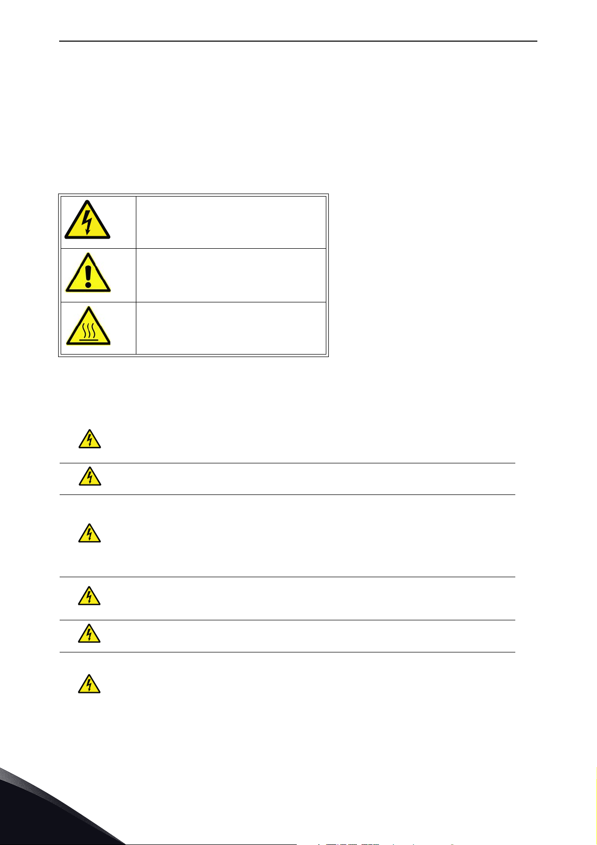
1. SAFETY
This manual contains clearly marked cautions and warnings which are intended for your personal
safety and to avoid any unintentional damage to the product or connected appliances.
Please read the information included in cautions and warnings carefully.
The cautions and warnings are marked as follows:
Table 1. Warning signs
= DANGER! Dangerous voltage
= WARNING or CAUTION
= Caution! Hot surface
1.1 Danger
The components of the power unit are live when the drive is connected to mains
potential. Coming into contact with this voltage is extremely dangerous and may
cause death or severe injury.
The motor terminals U, V, W and the brake resistor terminals are live when the
AC drive is connected to mains, even if the motor is not running.
After disconnecting the AC drive from the mains, wait until the indicators on the
keypad go out (if no keypad is attached see the indicators on the cover). Wait 5
more minutes before doing any work on the connections of the drive. Do not open
the cover before this time has expired. After expiration of this time, use a measuring equipment to absolutely ensure that no
absence of voltage before starting any electrical work!
The control I/O-terminals are isolated from the mains potential. However, the
relay outputs and other I/O-terminals may have a dangerous control voltage
present even when the AC drive is disconnected from mains.
voltage is present.
Always ensure
Before connecting the AC drive to mains make sure that the front and cable covers of the drive are closed.
During a ramp stop (see the Application Manual), the motor is still generating
voltage to the drive. Therefore, do not touch the components of the AC drive
before the motor has completely stopped. Wait until the indicators on the keypad
go out (if no keypad is attached see the indicators on the cover). Wait additional 5
minutes before starting any work on the drive.
Local contacts: http://drives.danfoss.com/danfoss-drives/local-contacts/
1
Page 5
Safety vacon • 3
13006.emf
13006.emf
13006.emf
13006.emf
13006.emf
13006.emf
13006.emf
13006.emf
13006.emf
13006.emf
1.2 Warnings
The AC drive is meant for fixed installations only.
Do not perform any measurements when the AC drive is connected to the mains.
The earth leakage current of the AC drives exceeds 3.5mA AC. According to stan-
dard EN61800-5-1, a reinforced protective ground connection must be ensured.
See chapter 1.3.
If the AC drive is used as a part of a machine, the machine manufacturer is
responsible for providing the machine with a supply disconnecting device (EN
60204-1).
Only spare parts delivered by VACON
®
can be used.
At power-up, power break or fault reset the motor will start immediately if the
start signal is active, unless the pulse control for
Start/Stop logic has been selected
Futhermore, the I/O functionalities (including start inputs) may change if parameters, applications or software are changed. Disconnect, therefore, the motor if
an unexpected start can cause danger.
The motor starts automatically after automatic fault reset if the auto restart
function is activated. See the Application Manual for more detailed information.
Prior to measurements on the motor or the motor cable, disconnect the motor
cable from the AC drive.
Do not touch the components on the circuit boards. Static voltage discharge may
damage the components.
Check that the EMC level of the AC drive corresponds to the requirements of your
supply network.
.
Local contacts: http://drives.danfoss.com/danfoss-drives/local-contacts/
1
Page 6

vacon • 4 Safety
13006.emf 13006.emf
1.3 Earthing and earth fault protection
CAUTION!
The AC drive must always be earthed with an earthing conductor connected to the earthing terminal
marked with .
The earth leakage current of the drive exceeds 3.5mA AC. According to EN61800-5-1, one or more
of the following conditions for the associated protective circuit shall be satisfied:
b) The protective conductor shall have a cross-sectional area of at least 10 mm2 Cu or 16
mm2 Al, through its total run.
c) Where the protective conductor has a cross-sectional area of less than 10 mm2 Cu or 16
mm2 Al, a second protective conductor of at least the same cross-sectional area shall be
provided up to a point where the protective conductor has a cross-sectional area not less
than 10 mm2 Cu or 16 mm2 Al.
d) Automatic disconnection of the supply in case of loss of continuity of the protective conduc-
tor.
The cross-sectional area of every protective earthing conductor which does not form part of the
supply cable or cable enclosure shall, in any case, be not less than:
-2.5mm
-4mm
2
if mechanical protection is provided or
2
if mechanical protection is not provided.
The earth fault protection inside the AC drive protects only the drive itself against earth faults in the
motor or the motor cable. It is not intended for personal safety.
Due to the high capacitive currents present in the AC drive, fault current protective switches may
not function properly.
Do not perform any voltage withstand tests on any part of the AC drive. There is
a certain procedure according to which the tests shall be performed. Ignoring this
procedure may result in damaged product.
NOTE! You can download the English and French product manuals with applicable safety,
warning and caution information from
http://drives.danfoss.com/knowledge-center/technical-documentation/.
REMARQUE Vous pouvez télécharger les versions anglaise et française des manuels produit
contenant l’ensemble des informations de sécurité, avertissements et mises en garde
applicables sur le site http://drives.danfoss.com/knowledge-center/technical-documentation/
.
Local contacts: http://drives.danfoss.com/danfoss-drives/local-contacts/
1
Page 7
Modbus - general info vacon • 5
11608_uk
Master´s
message
Slave
response
Start
Address
Function
Data
CRC
End
Start
Address
Function
Data
CRC
End
2. MODBUS - GENERAL INFO
Modbus is a communication protocol developed by Modicon systems. In simple terms, it is a way of
sending information between electronic devices. The device requesting the information is called the
Modbus Master and the devices supplying information are Modbus Slaves. The Master can also
write information to the Slaves. Modbus is typically used to transmit signals from instrumentation
and control devices back to a main controller or data gathering system.
Standard Modbus network contains one Master device and up to 247 Slave devices. In ModbusRTU
networks it is mandatory to define a unique Slave Address (or Unit identifier number) for the every
Slave Device. Slave Address is a number between 1 and 247. Modbus ASCII mode is not supported.
The Modbus communication interface is built around messages. The format of these Modbus messages is independent of the type of physical interface used. The same protocol can be used regardless of the connection type. Because of this, Modbus gives the possibility to easily upgrade the
hardware structure of an industrial network, without the need for large changes in the software. A
device can also communicate with several Modbus nodes at once, even if they are connected with
different interface types, without the need to use a different protocol for every connection.
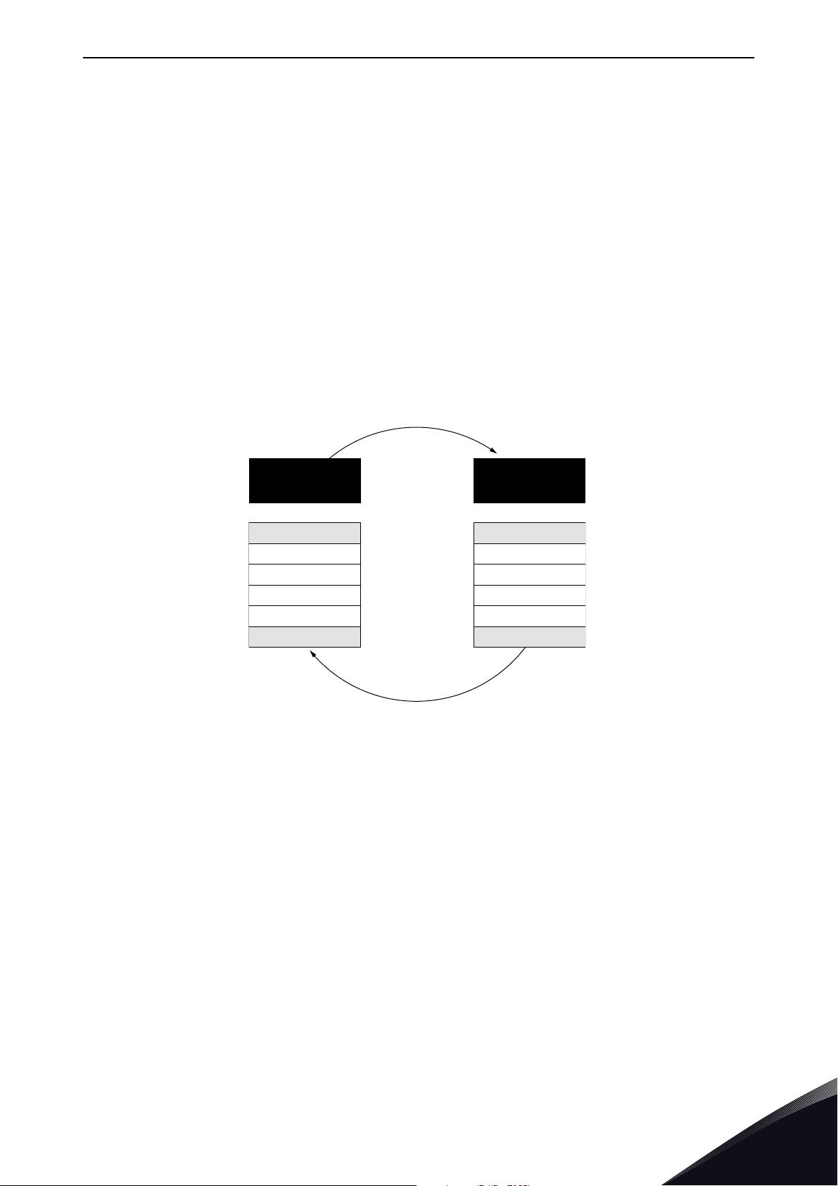
Figure 1.Basic structure of Modbus frame
On simple interfaces like RS485, the Modbus messages are sent in plain form over the network. In
this case the network is dedicated to Modbus.
Each Modbus message has the same structure. Four basic elements are present in each message.
The sequence of these elements is the same for all messages, to make it easy to parse the content
of the Modbus message. A conversation is always started by a master in the Modbus network. A
Modbus master sends a message and—depending of the contents of the message—a slave takes
action and responds to it. Addressing in the message header is used to define which device should
respond to a message. All other nodes on the Modbus network ignore the message if the address
field does not match their own address.
Your VACON
tact VACON
with the Drive Info File taken with VACON
®
20 family AC drive is equipped with Modbus support as standard. If you need to con-
®
service in problems related to Modbus, send a description of the problem together
®
Live to customer support. If possible, also send a "Wire-
shark" log from the situation if applicable.
Local contacts: http://drives.danfoss.com/danfoss-drives/local-contacts/
2
Page 8
vacon • 6 Modbus - general info
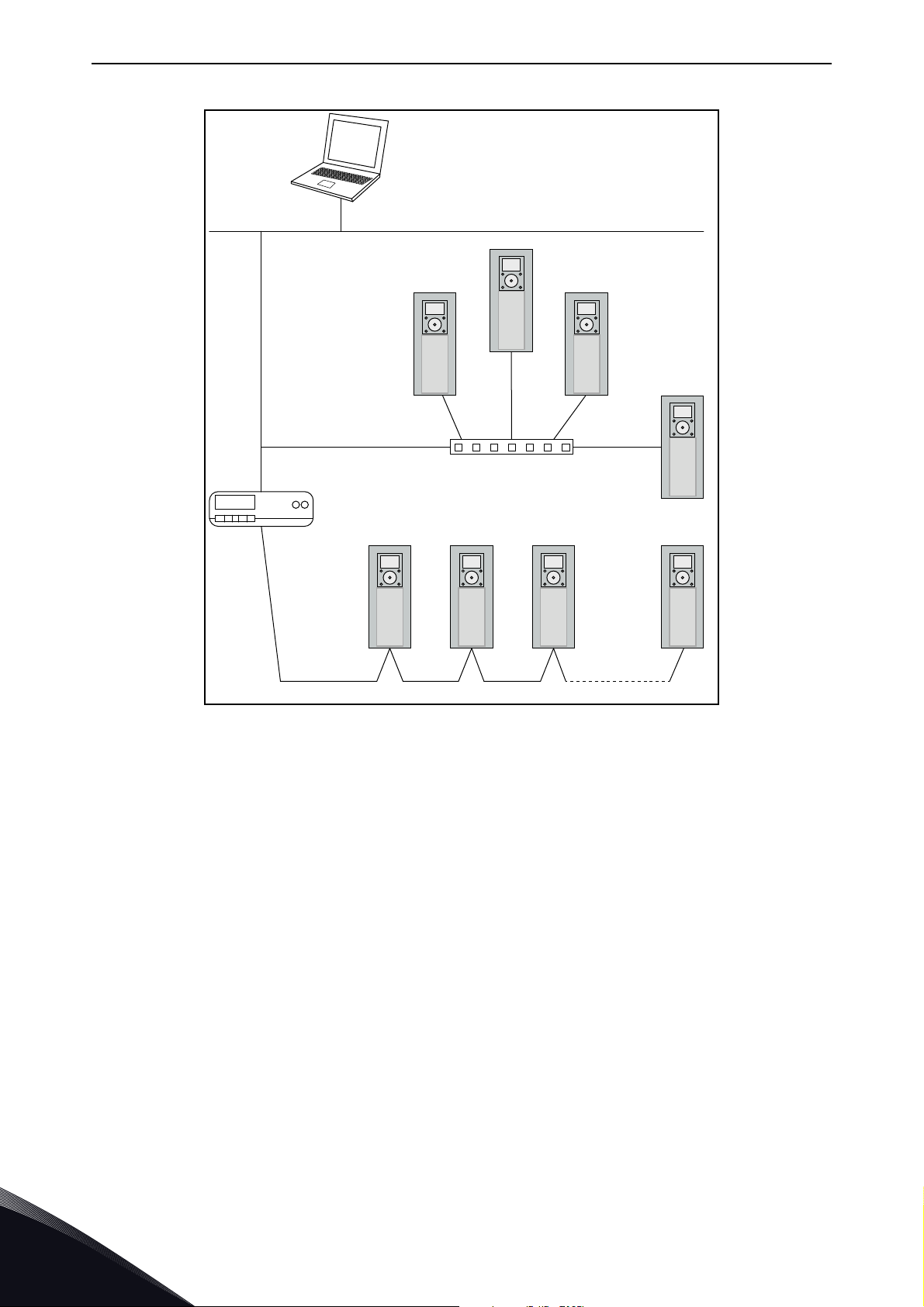
Ethernet
Modbus TCP
Switch
Modbus
RTU
master
Modbus RTU
11781_uk
Figure 2.Principal example diagram of Modbus
2.1 Restrictions
When a fieldbus option board or an OPTBH option board has been installed, Modbus is not working.
2
Local contacts: http://drives.danfoss.com/danfoss-drives/local-contacts/
Page 9

Modbus technical data vacon • 7
3. MODBUS TECHNICAL DATA
3.1 Modbus RTU protocol
Modbus RTU is the only supported transmission mode. Modbus ASCII mode is not supported.
Table 2.
Interface RS-485
Data transfer method RS-485 MS/TP, half-duplex
Transfer cable STP (Shielded Twisted Pair)
Connector
Connections and
communications
Electrical isolation Functional
Modbus RTU
Bitrate
Addresses 1 to 247
3.2 Connections and wiring
2.5 mm
As described in “Modicon Modbus Protocol Reference Guide”
300, 600, 1200, 2400, 4800, 9600, 19200,
38400, and 57600 bits/s
2
The maximum length of an RS-485 cable depends on the bitrate used, the cable (gauge, capacitance
or characteristic impedance) and the number of devices in the bus. The Modbus RTU specification
states that for a maximum 9600 bits/second bitrate and AWG26 or wider gauge, the maximum
length is 1000 meters. The actual cable length used in an installation can be lower than this number
depending on the aforementioned parameters.
Local contacts: http://drives.danfoss.com/danfoss-drives/local-contacts/
3
Page 10

vacon • 8 Installation
10
5
4. INSTALLATION
4.1 Installation in VACON® 20 family AC drives
The connection for RS485 is on the standard I/O terminals (A and B). See VACON® 20 or VACON® 20
X /CP Installation Manual depending on the drive you are using.
4.1.1 Preparation for use through RS485
Strip about 15 mm of the RS485 cable and cut off the grey cable shield. Remember to do this for both bus cables (except for the last device).
Leave no more than 10 mm of the cable outside the terminal block and strip the
cables at about 5 mm to fit in the terminals. See picture below.
1
2
3
Also strip the cable now at such a distance from the terminal that you can fix it to
the frame with the grounding clamp. Strip the cable at a maximum length of 15
mm. Do not strip the aluminium cable shield!
Then connect the cable to its appropriate terminals on VACON® 20 CP AC drive
standard terminal block, terminals A and B (A = negative, B = positive).
Using the cable clamp included in the supply of the drive, ground the shield of
the RS485 cable to the frame of the AC drive.
4
Local contacts: http://drives.danfoss.com/danfoss-drives/local-contacts/
Page 11
Installation vacon • 9
4 5 13 14 15 16 2018
123678910
22 23 26
2425
AI2 GND DO- DI4 DI5 DI 6 AO DO+ R13 R14 * R24
+10VAI1 GND 24V DI-C DI1 DI2 DI 3 A B R21 R22
DI
Enco Nor
AO
V mA
AI2
V mA
RS485
- term
ON
OFF
J500
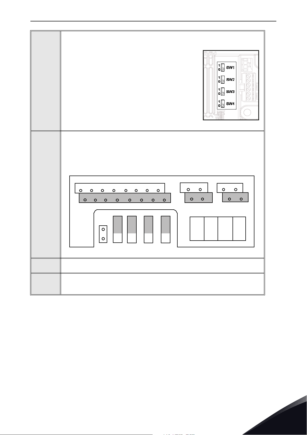
NOTE! This step is valid only for VACON® 20 CP and VACON® 20 X.
®
If VACON
the bus, the bus termination must be set. Locate the
switches to the right of the control terminals and turn
the SW4 switch to position “0”. Biasing is built in the
termination resistor.
20 Cold Plate drive is the last device on
4
NOTE! This step is valid only for VACON® 20.
The RS-485 bus is terminated with termination resistors of 120 ohms in both
ends. VACON
default (presented below). The termination resistor can be switched on and off
with the right hand dip switch located above IO-terminals in the front of the drive
(see below). Biasing is built in the termination resistor.
®
20 has a built-in termination resistor which is switched off as a
5
6
7
NOTE: When planning the cable runs, remember to keep the distance between
the fieldbus cable and the motor cable at a minimum of 30 cm.
The bus termination must be set for the first and the last device of the fieldbus
line. We recommend that the first device terminated is the Master device.
Local contacts: http://drives.danfoss.com/danfoss-drives/local-contacts/
4
Page 12

vacon • 10 Fieldbus parametrization
5. FIELDBUS PARAMETRIZATION
The following chapter describes briefly how to parametrise the AC drive in order for the motor to be
controllable via fieldbus. These instructions are written for basic applications. For more
information, consult the application-specific manual.
In order for the AC drive to accept commands from the fieldbus network, the control place of the AC
drive has to be set to fieldbus. The default value of the parameter "Control Place" is usually I/O. Note
that if the control unit firmware is updated, the default settings are restored. In addition, some
applications may have the remote speed reference selection set by default to other than fieldbus. In
these cases, the speed reference selection must be set to fieldbus, in order for the speed reference
to be controlled via fieldbus.
NOTE! The motor control mode should be selected to support the used process and profile.
The navigation path to the fieldbus parameters may differ from application to application. The
®
exemplary paths below apply to the VACON
20 family AC drive.
5.1 Fieldbus control and basic reference selection
The following tables list some of the parameters related to fieldbus control. See the application
specific manuals for more detailed information.
Parameters can be read and written by using the drive panel, PC Tool or fieldbus protocol. Notice
that some of connection parameters for fieldbus may need to be set (depending on your
configuration) via panel or PC tool, before you can connect over fieldbus and write application
parameters.
Table 3. Parametrization for VACON® 20 family AC drive (Standard application)
Parameter name Value
Control mode Frequency Speed
Remote control place Fieldbus CTRL
Local / remote Remote
Fieldbus ref. sel. Fieldbus
5.2 Modbus RTU parameters and monitoring values
5
Table 4 .
Code Parameter Min Max Unit Default ID Description
When no fieldbus board or no OPTBH board has been installed, the following values are visible:
Status of Modbus communication.
Format: xx.yyy where
xx = 0 - 64 (Number of error messages)
V2.1 Communication status 808
Local contacts: http://drives.danfoss.com/danfoss-drives/local-contacts/
This counter saturates when 64 error
messages are detected
yyy = 0 - 999 (Number of good messages)
This counter restarts counting from 0
when 999 good messages are detected
Page 13

Fieldbus parametrization vacon • 11
Table 4 .
Code Parameter Min Max Unit Default ID Description
The fault code related to the last counted
bad messages is shown:
1 = Illegal function
2 = Illegal address
V2.9 *
P2.2 Fieldbus protocol 0 1 0 809
P2.3 Slave address 1 247 1 810
P2.4 Baud rate 0 8 5 811
P2.6 Parity type 0 2 0 813
P2.7
P2.8
Last communication
fault
Communication time
out
Reset communication
status
0 255 s 10 814
01 0815
3 = Illegal data value
816
4 = Illegal slave device
53 = USART receive fault (parity error/
frame error/USART buffer overflow)
90 = Receive buffer overflow
100 = Frame CRC Error
101 = Ring buffer overflow
0 = Not used
1 = Modbus used
0 = 300
1 = 600
2 = 1200
3 = 2400
4 = 4800
5 = 9600
6 = 19200
7 = 38400
8 = 57800
Parity type:
0 = None
1 = Even
2 = Odd
Stop bit:
- 2-bits with parity type “None”;
- 1-bit with parity type “Even” and “Odd”.
(*) Only on VACON® 20CP/X.
5.2.1 Fieldbus protocol
Use this parameter to activate the Modbus protocol.
5.2.2 Slave address
Each slave must have a unique address (from 1 to 247) so that it can be addressed independently
from other nodes.
5.2.3 Baud rate
Select the communication speed for the network. The default value is 9600 baud.
Local contacts: http://drives.danfoss.com/danfoss-drives/local-contacts/
5
Page 14

vacon • 12 Fieldbus parametrization
5.2.4 Parity type
You can select the parity type for the network. Modbus RTU specifies the stop bit configuration
shown in table below. You can modify this stop bit configuration manually using parameter.
Table 5. Parity type and stop bits
Parity Stopbits
Even 1
Odd 1
None 2
5.2.5 Communication timeout
Modbus initiates a communication error for a time defined with this parameter. '0' means that no
fault is generated.
5.2.6 Reset communication status
Used to reset the communication status shown in monitor value V2.1.
5.2.7 Communication status
The Communication status shows how many good and bad messages the drive has received. The
Communication status includes a common error counter that counts CRC and parity errors and a
counter for good messages.
Only messages to the current slave in use are counted in the good messages.
Table 6. Communication status description
Good messages
0…999 Number of messages received without errors
Bad messages
0…64 Number of messages received with errors
5
Local contacts: http://drives.danfoss.com/danfoss-drives/local-contacts/
Page 15

Communications vacon • 13
6. COMMUNICATIONS
Features of the Modbus-Vacon interface:
• Direct control of VACON® drive (e.g. Run, Stop, Direction, Speed reference, Fault reset)
®
• Full access to all VACON
®
• Monitor VACON
status (e.g. Output frequency, Output current, Fault code)
6.1 Modbus address area
The Modbus interface of VACON® 20/X uses the ID numbers of the application parameters as
addresses. The ID numbers can be found in the parameter tables described in specific Application
Manual.
When several parameters / monitoring values are read at a time, they must be consecutive.
11 addresses can be read and the addresses can be parameters or monitoring values.
NOTE: With some PLC manufacturers, the interface driver for Modbus RTU communicationmay
contain an offset of 1 (the ID number to be used would then subtract 1).
parameters
6.2 Supported Modbus Functions
The VACON® variables and fault codes as well as the parameters can be read and written from
Modbus. The parameter addresses are determined in the application. Every parameter and actual
value have been given an ID number in the application. The ID numbering of the parameter as well
as the parameter ranges and steps can be found in the application manual in question. The
parameter value must be given without decimals. If several parameters/actual values are read with
one message, the addresses of the parameters/actual values must be consecutive.
Table 7. Modbus RTU
Func t i o n
(dec)
3 Read Holding Registers All ID numbers No
4 Read Input Registers All ID numbers No
6 Write Single Register All ID numbers Yes
16 Write Multiple Registers All ID numbers Yes
Function Name Address
Broadcast
messages
Local contacts: http://drives.danfoss.com/danfoss-drives/local-contacts/
6
Page 16

vacon • 14 Communications
6.3 Modbus data mapping
6.3.1 Modbus process data in VACON® 20 Application ACCN1004
Process data is an address area for fieldbus control. Fieldbus control is active when the value of
parameter 2.1 (Control place) is 1 (= fieldbus). The content of the process data can be programmed
in the application.The following tables present the process data contents in VACON
Please refer to VACON
ID Modbus register Name Scale Type
2101 32101, 42101 FB Status Word - Binary coded
2102 32102, 42102 FB General Status Word - Binary coded
2103 32103, 42103 Actual speed 0.01 %
2104 32104, 42104
2105 32105, 42105
2106 32106, 42106
®
20 Complete Manual for details.
Table 8. Output process data
Programmable by P10.1
(Default: Frequency reference)
Programmable by P10.2
(Default: Output frequency)
Programmable by P10.3
(Default: Motor speed)
--
0.01 +/- Hz
1 +/- Rpm
®
20 Application.
2107 32107, 42107
2108 32108, 42108
2109 32109, 42109
2110 32110, 42110
2111 32111, 42111
Programmable by P10.4
(Default: Motor voltage)
Programmable by P10.5
(Default: Motor torque)
Programmable by P10.6
(Default: Motor current)
Programmable by P10.7
(Default: Motor power)
Programmable by P10.8
(Default: DC link voltage)
0.1 V
0.1 +/- % (of nominal)
0.01 A
0.1 +/- % (of nominal)
1V
6
Local contacts: http://drives.danfoss.com/danfoss-drives/local-contacts/
Page 17

Communications vacon • 15
Table 9. Input process data
ID Modbus register Name Scale Type
2001 32001, 42001 FB Control Word Binary coded
2002 32002, 42002 FB General Control Word Binary coded
2003 32003, 42003 Actual speed 0.01 %
2004 32004, 42004 Programmable by P10.9
2005 32005, 42005 Programmable by P10.9
2006 32006, 42006 Programmable by P10.9
2007 32007, 42007 Programmable by P10.9
2008 32008, 42008 Programmable by P10.9
2009 32009, 42009 - - 2010 32010, 42010 - - 2011 32011, 42011 - - -
NOTE! 2004 - 2007 can set as PID Control Reference by setting P15.1(Setpoint selection) or PID
Actual value by setting P15.4 (Feedback value selection)!
2004 - 2007 can be set as the Analogue Output by P9.1, P9.5, P9.9.
2004 - 2008 can set as Aux Control Word with P10.9:
b0: Run enable
b1: acc / dec ramp 2 selection
b2: freq reference 2 selection
NOTE!
• AUX CW is active when configured, even if control place is not the fieldbus
• b0 Run enable is computed in AND with a possible Run enable signal from digital input. Fall
of enable will cause coasting stop.
Status word (output process data)
Information about the status of the device and messages is indicated in the Status word. The Status
word is composed of 16 bits the meanings of which are described in the table below:
Table 10. Status word (output process data)
Description
Bit
Value = 0 Value = 1
B0, RDY Drive not ready Drive ready
B1, RUN Stop Run
B2, DIR Clockwise Counter-clockwise
B3, FLT No fault Fault active
B4, W No alarm Alarm active
B5, AREF Ramping Speed reference reached
B6, Z - Drive is running at zero speed
B7 - B15 - -
Local contacts: http://drives.danfoss.com/danfoss-drives/local-contacts/
6
Page 18

vacon • 16 Communications
General status word (output process data)
Information about the status of the device and messages is indicated in the General status word. The
General status word is composed of 16 bits the meanings of which are described in the table below:
Table 11. General status word (output process data)
Description
Bit
Value = 0 Value = 1
B0, RDY Drive not ready Drive ready
B1, RUN Stop Run
B2, DIR Clockwise Counter-clockwise
B3, FLT No fault Fault active
B4, W No alarm Alarm active
B5, AREF Ramping Speed reference reached
B6, Z - Drive is running at zero speed
B7, F - Fieldbus control active
B8 - B12 - -
Bit
I/O PC tool Keypad Fieldbus
B131000
B140110
Control Place
B150101
Actual speed (output process data)
This is actual speed of the AC drive. The scaling is -10000...10000. The value is scaled in percentage
of the frequency area between set minimum and maximum frequency.
Control word (input process data)
The three first bits of the control word are used to control the AC drive. By using control word it is
possible to control the operation of the drive. The meanings of the bits of control word are explained
in the table below:
Table 12. Control word (input process data)
Description
Bit
Value = 0 Value = 1
B0, RUN Stop Run
B1, DIR Clockwise Counter-clockwise
B2, RST Rising edge of this bit will reset active fault
B5 Not used
Speed reference (input process data)
6
This is the Reference 1 to the AC drive. Used normally as Speed reference. The allowed scaling is
0...10000. The value is scaled in percentage of the frequency area between the set minimum and
maximum frequencies.
Local contacts: http://drives.danfoss.com/danfoss-drives/local-contacts/
Page 19

Communications vacon • 17
6.3.2 Modbus process data in VACON® 20X and VACON® CP Application ACIT1075
Process data is an address area for fieldbus control. Fieldbus control is active when the value of
parameter 1.11 (Control place) is 2 (= fieldbus). The content of the process data can be programmed
in the application.The following tables present the process data contents in VACON
Application. Please refer to VACON
®
20 CP X Multipurpose Application Manual for details.
®
ACIT1075
6.3.2.1
Modbus
register
2001 Control word Drive control
2002 General control word Not used
2003 Speed reference Reference
2004 Fieldbus Data IN 1 Programmable 0...10000
2005 Fieldbus Data IN 2 Programmable 0...10000
2006 Fieldbus Data IN 3 Programmable 0...10000
Fieldbus Data IN: Master -> Slave
Table 13.
Name Description Range
Binary coded:
b0: Run
b1: Reverse
b2: Fault Reset(on edge)
b8: forces control place to fieldbus
b9: forces reference source to
fieldbus
0...10000 as 0,00...100,00% of
Min freq. - Max freq. range
2007 Fieldbus Data IN 4 Programmable 0...10000
2008 Fieldbus Data IN 5 Programmable 0...10000
2009 Fieldbus Data IN 6 Not used 2010 Fieldbus Data IN 7 Not used 2011 Fieldbus Data IN 8 Not used -
NOTE!
• CW b0 Run is acquired on edge, only if the drive is in Ready state (see Status Word b0) and
actual control place is Fieldbus.
• CW b2 Fault Reset is active even if control place is not the Fieldbus.
Local contacts: http://drives.danfoss.com/danfoss-drives/local-contacts/
6
Page 20

vacon • 18 Communications
Fieldbus data input mapping
Fieldbus Data inputs from 1 to 5 can be configured, with parameters P11.9 - P11.12, as:
Table 14.
Process Data IN Description Note
• b0 Enable is considered only when
control place is the Fieldbus. It is
computed in AND with a possible
enable from digital input. Fall of
enable will cause coasting stop.
• b2 FreqRef2 Sel is considered only
when control place is the Fieldbus.
• functions related to bit1, b3 and b4
are available also when control
place is not the Fieldbus. Aux CW
must anyway be mapped onto a
PDI, by means of parameter P11.9.
Aux Control Word
b0: enable
b1: acc/dec ramp 2 selection
b2: freq reference 2 selection
b3: digital output 1 control
b4: digital output 2 control
active if P12.1 = 3, range 0 -
PID Setpoint
10000 as 0 - 100.00% of regulation.
active if P12.4 = 2, range 0 -
PID Actual value
10000 as 0 - 100.00% of regulation.
Analogue Out Cntrl
active if P5.1 = 8, range 0 10000 as 0 - 100.00% of output.
6
Local contacts: http://drives.danfoss.com/danfoss-drives/local-contacts/
Page 21

Communications vacon • 19
6.3.2.2 Fieldbus Data OUT: Slave -> Master
Table 15.
Modbus
Register
2101 Status word Drive state
2102 General Status word Drive state
2103 Actual speed Actual speed
2104 Fieldbus Data OUT 1 Programmable See P11.1
2105 Fieldbus Data OUT 2 Programmable See P11.2
2106 Fieldbus Data OUT 3 Programmable See P11.3
2107 Fieldbus Data OUT 4 Programmable See P11.4
2108 Fieldbus Data OUT 5 Programmable See P11.5
2109 Fieldbus Data OUT 6 Programmable See P11.6
2110 Fieldbus Data OUT 7 Programmable See P11.7
Name Description Range
Binary coded:
b0: Ready
b1: Run
b2: Reverse
b3: Fault
b4: Warning
b5: Freq. reference reached
b6: Zero speed
As Status word and:
b7: Control place is fieldbus
0...10000 as 0.00...100.00%
of Min freq. - Max freq.
range
2111 Fieldbus Data OUT 8 Programmable See P11.8
Local contacts: http://drives.danfoss.com/danfoss-drives/local-contacts/
6
Page 22

vacon • 20 Communications
6.4 Example messages
6.4.1 Example 1 - Write Process Data
Write the process data 42001…42003 with command 16 (Preset Multiple Registers).
Command Master - Slave:
Table 16.
ADDRESS 01 hex Slave address 1 hex (= 1)
FUNCTION 10 hex Function 10 hex (= 16)
Starting address HI 07 hex
Starting address LO D0 hex
No. of registers HI 00 hex
No. of registers LO 03 hex
Byte count 06 hex Byte count 06 hex (= 6)
DATA
ERROR
CHECK
Message frame:
01 10 07 D0 00 03 06 00 01 00 00 13 88 C8 CB
Data HI 00 hex
Data LO 01 hex
Data HI 00 hex
Data LO 00 hex
Data HI 13 hex
Data LO 88 hex
CRC HI C8 hex
CRC LO CB hex
Table 17.
Starting address 07D0 hex (= 2000)
Number of registers 0003 hex (= 3)
Data 1 = 0001 hex (= 1). Setting control word run bit to 1.
Data 2 = 0000 hex (= 0).
Data 3 = 1388 hex (= 5000), Speed Reference to 50.00%
CRC field C8CB hex (= 51403)
6
The reply to Preset Multiple Registers message is the echo of 6 first bytes.
Answer Slave - Master:
Table 18.
ADDRESS 01 hex Slave address 1 hex (= 1)
FUNCTION 10 hex Function 10 hex (= 16)
DATA
ERROR
CHECK
Starting address HI 07 hex
Starting address LO D0 hex
No. of registers HI 00 hex
No. of registers LO 03 hex
CRC HI 80 hex
CRC LO 85 hex
Local contacts: http://drives.danfoss.com/danfoss-drives/local-contacts/
Starting address 07D0 hex (= 2000)
Number of registers 0003 hex (= 3)
CRC 8085 hex (= 32901)
Page 23

Communications vacon • 21
Reply frame:
Table 19.
01 10 07 D0 00 03 80 85
6.4.2 Example 2 - Read process data
Read the Process Data 42103…42104 with command 4 (Read Input Registers): for this example when
using ACCN1004 set P10.1=1, when using ACIT1075 set P11.1=0.
Command Master - Slave:
Table 20.
ADDRESS 01 hex Slave address 1 hex (= 1)
FUNCTION 04 hex Function 4 hex (= 4)
Starting address HI 08 hex
DATA
ERROR
CHECK
Message frame:
01 04 08 36 00 02 93 A5
The reply to the Read Input Registers message contains the values of the read registers.
Answer Slave - Master:
ADDRESS 01 hex Slave address 1 hex (= 1)
FUNCTION 04 hex Function 4 hex (= 4)
DATA
Starting address LO 36 hex
No. of registers HI 00 hex
No. of registers LO 02 hex
CRC HI 93 hex
CRC LO A5 hex
Table 21.
Byte count 04 hex Byte count 4 hex (= 4)
Data HI 13 hex
Data LO 88 hex
Starting address 0836 hex (= 2102)
Number of registers 0002 hex (= 2)
CRC field 93A5 hex (= 37797)
Table 22.
Actual Speed = 1388 hex (=5000 => 50.00%)
Data HI 09 hex
Data LO C4 hex
ERROR
CHECK
Reply frame:
01 04 04 13 88 09 C4 78 E9
Local contacts: http://drives.danfoss.com/danfoss-drives/local-contacts/
CRC HI 78 hex
CRC LO E9 hex
Table 23.
Output Frequency = 09C4 hex (=2500 =>25.00Hz)
CRC field 78E9 hex (=30953)
6
Page 24

vacon • 22 Fault tracing
7. F AULT TRACING
When an unusual operating condition is detected by the AC drive control diagnostics, the drive initiates a notification visible, for example, on the keypad. The keypad will show the ordinal number of
the fault, the fault code.
The fault can be reset with the Reset button on the control keypad or via the I/O terminal. The faults
are stored in the Fault history menu which can be browsed. The different fault codes you will find
in the table below. This fault table presents only the faults related to the fieldbus in use.
NOTE! When contacting distributor or factory because of a fault condition, always write down all
texts and codes on the keypad display and send a description of the problem together with the
Info File
to your local support.
7.1 Typical fault conditions
Table 24. Typical fault conditions
Fault condition Possible cause Remedy
Drive
Termination
resistor
Cabling
Grounding Inadequate grounding.
Connections
Parameter
Missing or excessive termination resistor.
• Supply or motor cables are located
too close to the fieldbus cable
• Wrong type of fieldbus cable
• Too long cabling
Faulty connections.
• Excessive stripping of cables
• Conductors in wrong terminals
• Too loose connections of conductors
• Faulty address
• Overlapping slave addresses
• Wrong baud rate
• Wrong control place selected
Install termination resistors at both ends of the
fieldbus line.
Ensure grounding in all
points on the net
7.2 RS-485 bus biasing
When none of the devices on the RS-485 bus is sending data, all devices are in idle status. This being
the case, the bus voltage is in indefinite state, usually near 0 V due to the termination resistors. This
may cause problems in character reception because the single characters in serial communication
begin with start bit referring to bus status '0' with voltage of less than -200mV whereas the bus status '1' corresponds to bus voltage of more than +200mV. The RS-485 standard considers the voltage
interval -200mV...+200mV as undefined state. Bus biasing is therefore needed to maintain the voltage in status ‘1’ (above +200mV) also between the messages.
7
By activating the line termination using the dedicated dip switch described in Chapter 4.1.1, also a
560 Ohm resistor for line polarization is activated.
Local contacts: http://drives.danfoss.com/danfoss-drives/local-contacts/
Page 25

Fault tracing vacon • 23
.
Check cabling
Check grounding
9330A.emf
No communication
Counter OK
Poor
communication
Check communi-
cation status (par.
Counter does not
run
Counter for bad
frames
increases
Check fieldbus
parameters
bus parameters in
menu
Check other field-
Check selected
protocol
Check termination
resistors
Check that both
ends of the fieldbus
line hav termi-
nation resistors
(chapter 4)
Check parameters
e
Is the device in
READY state?
Check Master’s
parameters
Is fieldbus selected
as control place?
Does Master give
RUN command?
Check cabling
Check termination
resistors
Other bus devices
Check connections
Check the led on
keypad
Check external
interlockings (I/O)
Check configura-
tions (Sla e add-
ress, baudrate etc.)
v
Check distances
between cables,
see chapter 4.
Check cable types,
see chapter 3.
Check grounding,
see chapter 4. Re-
member to make
grounding for each
device!
Check terminals for
loose connections
Check stripping of
cables and
conductors, see
chapter 4.
Use keypad to
monitor variable
Check that both
ends of th fieldbus
line have t rmina-
tion resistors
(chapter 4)
e
e
Check cable for
cuts
Check correct place-
ment of conductors
in terminals
Check other
necessary devices
Drive does not
start from the bus
Check control place
parameter setting
V2.1)
7.3 Other fault conditions
The following fault tracing diagram will help you to locate and fix some of the most usual problems.
If the problem persists contact your local distributor.
Figure 3. Fault tracing diagram for Modbus RTU
Local contacts: http://drives.danfoss.com/danfoss-drives/local-contacts/
7
Page 26

vacon • 24 Quick setup
8. QUICK SETUP
Following these instructions, you can easily and fast set up your Modbus for use:
Choose control place.
1
2
A. Press LOC/REM button on keypad to select
Select Fieldbus as remote control place. The parameter depends on the appli-
B.
cation used:
• P2.1 in VACON
• P1.11 in VACON
Make these settings in the master software
A. Set Control Word to '0' by writing the data 0000h to the register 2001
B. Set Control Word to '1' by writing the data 0001h to the register 2001
C. AC drive status is RUN
D. Set Speed Reference value to '5000' (=50.00%) by writing the data 1388h to the
register 2003
Actual speed is 5000 (25.00 Hz if MinFreq is 0.00 Hz and MaxFreq is 50.00 Hz)
E.
F. Set Control Word to '0' by writing the data 0000h to the register 2001
G. AC drive status is STOP.
.
d
®
20
®
20 X and VACON® 20 CP
Remote Control Place
.
d
.
d
.
d
8
Local contacts: http://drives.danfoss.com/danfoss-drives/local-contacts/
Page 27

APPENDIX 1 - PROCESS DATA vacon • 25
9. APPENDIX 1 - PROCESS DATA
Process Data IN (Master to Slave)
Use of Process Data In variables depends on the used application. The configuration of the data is
free.
Process Data OUT (Slave to Master)
Use of Process Data Out variables depends on the used application.
The Fieldbus Master can read the AC drive’s actual values using process data variables.
Local contacts: http://drives.danfoss.com/danfoss-drives/local-contacts/
9
Page 28

www.danfoss.com
Vacon Ltd
Member of the Danfoss Group
Runsorintie 7
65380 Vaasa
Finland
Document ID:
DPD01925A
Rev. A
Sales code: DOC-INSV20MODBUS+DLUK
 Loading...