

Page 1

vacon 100 hvac
®
ac drives
application manual
Page 2

Page 3

PREFACE VACON · 3
PREFACE
Document ID: DPD01696K
Date: 11.04.2016
Software version: FW0065V032
ABOUT THIS MANUAL
This manual is copyright of Vacon Ltd. All Rights Reserved. The manual is subject to change
without prior notice.
In this manual, you can read about the functions of the Vacon® AC drive and how to use the
drive. The manual has the same structure than the menu of the drive (chapters 1 and 4-8).
Chapter 1, Quick Startup Guide
How to start the work with the control panel.
•
Chapter 2, Wizards
Setting up an application quickly.
•
Chapter 3, User Interfaces
The display types and how to use the control panel.
•
The PC tool Vacon Live.
•
The functions of the fieldbus.
•
Chapter 4, Monitoring menu
Data on the monitoring values.
•
Chapter 5, Parameter menu
A list of all the parameters of the drive.
•
Chapter 6, Diagnostics menu
Chapter 7, I/O and Hardware menu
Chapter 8, User settings, favourites and user level menus
Chapter 9, Monitoring value descriptions
Chapter10, Parameter descriptions
How to use the parameters.
•
Digital and analogue input programming.
•
Application-specific functions.
•
24-HOUR SUPPORT +358 (0)201 212 575 · EMAIL: [email protected]
Page 4
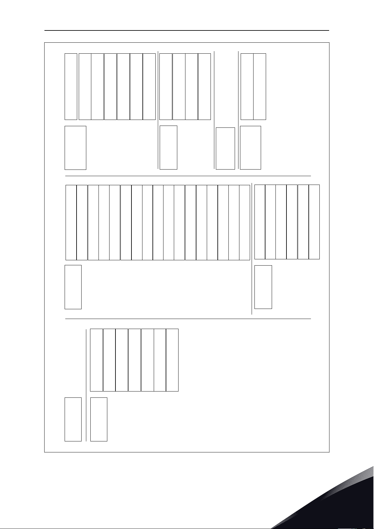
Index Min Max Unit Default ID DescriptionParameter
A
I
B C D E F G H
VACON · 4 PREFACE
Chapter 11, Fault tracing
The faults and their causes.
•
Resetting the faults.
•
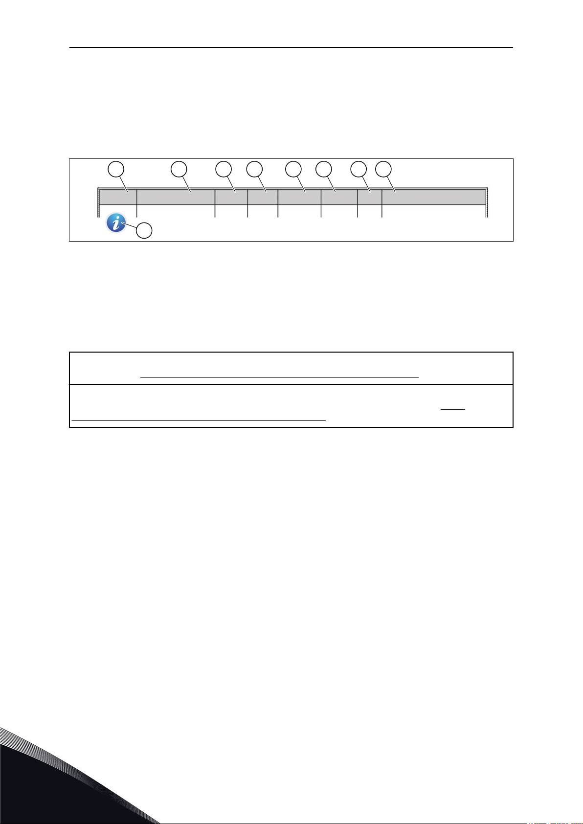
This manual includes a large quantity of parameter tables. These instructions tell you how to
read the tables.
A. The location of the parameter in the
menu, that is, the parameter number.
B. The name of the parameter.
C. The minimum value of the parameter.
D. The maximum value of the parameter.
E. The unit of the value of the parameter.
The unit shows if it is available.
NOTE! You can download the English and French product manuals with applicable safety, warning and caution
information from http://drives.danfoss.com/knowledge-center/technical-documentation/.
REMARQUE Vous pouvez télécharger les versions anglaise et française des manuels produit contenant l'ensemble des informations de sécurité, avertissements et mises en garde applicables sur le site http://
drives.danfoss.com/knowledge-center/technical-documentation/.
F. The value that was set in the factory.
G. The ID number of the parameter.
H. A short description of the values of the
parameter and/or its function.
I. When the symbol shows, you can find
more data about the parameter in
Chapter Parameter descriptions.
TEL. +358 (0)201 2121 · FAX +358 (0)201 212 205
Page 5

PREFACE VACON · 5
FUNCTIONS OF THE VACON® AC DRIVE
Wizards for startup, PID control, multipump and fire mode to make the commissioning
•
easy.
The Funct button for an easy change between the local and the remote control place. The
•
remote control place can be I/O or fieldbus. You can make a selection of the remote
control place with a parameter.
Run interlock input (Damper interlock). Drive does not start before this input is activated.
•
A control page to operate and monitor of the most important values quickly.
•
Different pre-heat modes to prevent condensation problems.
•
A maximum output frequency of 320 Hz.
•
A Real time clock and timer functions (an optional battery is necessary). It is possible to
•
program 3 time channels to get different functions on the drive.
An external PID controller is available. You can use it, for example, to control a valve with
•
the I/O of the AC drive.
A sleep mode function that automatically enables and disables the operation of the drive
•
to save energy.
A 2-zone PID controller with 2 different feedback signals: minimum and maximum
•
control.
2 setpoint sources for the PID control. You can make the selection with a digital input.
•
A function for PID setpoint boost.
•
A feedforward function to make the response to the process changes better.
•
A process value supervision.
•
A multipump control.
•
A pressure loss compensation to compensate pressure losses in the pipework for
•
example when the sensor is incorrectly placed near the pump or fan.
24-HOUR SUPPORT +358 (0)201 212 575 · EMAIL: [email protected]
Page 6

VACON · 6
TEL. +358 (0)201 2121 · FAX +358 (0)201 212 205
Page 7

TABLE OF CONTENTS VACON · 7
TABLE OF CONTENTS
Preface
About this manual 3
Functions of the Vacon® AC drive 5
1 Quick Startup Guide 11
1.1 Control panel and keypad 11
1.2 The displays 11
1.3 First start-up 12
1.4 Description of the applications 13
1.4.1 Vacon HVAC application 13
2 Wizards 20
2.1 PID mini-wizard 20
2.2 Multi-pump mini-wizard 21
2.3 Fire mode wizard 22
3 User interfaces 24
3.1 Navigation on the keypad 24
3.2 Using the graphical display 26
3.2.1 Editing the values 26
3.2.2 Resetting a fault 29
3.2.3 The Funct button 29
3.2.4 Copying the parameters 33
3.2.5 Comparing the parameters 35
3.2.6 Help texts 36
3.2.7 Using the Favourites menu 37
3.3 Using the text display 37
3.3.1 Editing the values 38
3.3.2 Resetting a fault 39
3.3.3 The Funct button 39
3.4 Menu structure 42
3.4.1 Quick setup 43
3.4.2 Monitor 43
3.5 Vacon Live 44
4 Monitoring menu 46
4.1 Monitor group 46
4.1.1 Multimonitor 46
4.1.2 Basic 47
4.1.3 Timer functions monitoring 49
4.1.4 PID1 controller monitoring 50
4.1.5 PID2 controller monitoring 51
4.1.6 Multi-pump monitoring 51
4.1.7 Fieldbus process data monitoring 52
5 Parameters menu 53
5.1 Group 3.1: Motor settings 53
5.2 Group 3.2: Start/stop setup 56
24-HOUR SUPPORT +358 (0)201 212 575 · EMAIL: [email protected]
Page 8

VACON · 8 TABLE OF CONTENTS
5.3 Group 3.3: Control reference settings 58
5.4 Group 3.4: Ramp and brakes setup 60
5.5 Group 3.5: I/O configuration 61
5.6 Group 3.6: Fieldbus data mapping 69
5.7 Group 3.7: Prohibit frequencies 70
5.8 Group 3.8: Limit supervisions 71
5.9 Group 3.9: Protections 72
5.10 Group 3.10: Automatic reset 74
5.11 Group 3.11: Timer functions 75
5.12 Group 3.12: PID-controller 1 78
5.13 Group 3.13: PID-controller 2 83
5.14 Group 3.14: Multipump 86
5.15 Group 3.16: Fire mode 87
5.16 Group 3.17: Application settings 88
5.17 Group 3.18: kWh pulse output settings 88
6 Diagnostics menu 89
6.1 Active faults 89
6.2 Reset faults 89
6.3 Fault history 89
6.4 Total counters 90
6.5 Trip counters 91
6.6 Software info 92
7 I/O and hardware menu 93
7.1 Basic I/O 93
7.2 Option board slots 95
7.3 Real time clock 96
7.4 Power unit settings 96
7.5 Keypad 98
7.6 Fieldbus 98
8 User settings, favourites and user level menus 99
8.1 User settings 99
8.1.1 Parameter backup 100
8.2 Favourites 101
8.2.1 Adding an item to the Favourites 101
8.2.2 Removing an item from the Favourites 102
8.3 User levels 103
8.3.1 Changing the access code of the user levels 103
9 Monitoring value descriptions 105
9.1 Basic 105
9.2 Timer functions 107
9.3 PID1 Controller 108
9.4 PID2 Controller 109
9.5 Multi-pump 109
9.6 Fieldbus data 110
TEL. +358 (0)201 2121 · FAX +358 (0)201 212 205
Page 9

TABLE OF CONTENTS VACON · 9
10 Parameter descriptions 112
10.1 Motor settings 112
10.1.1 Motor nameplate parameters 112
10.1.2 Motor control parameters 113
10.2 Start/Stop setup 117
10.3 References 124
10.3.1 Frequency reference 124
10.3.2 Preset frequencies 125
10.3.3 Motor potentiometer parameters 127
10.4 Ramps and brakes setup 128
10.5 I/O configuration 131
10.5.1 Programming of digital and analogue inputs 131
10.5.2 Digital inputs 137
10.5.3 Analogue inputs 142
10.5.4 Digital outputs 143
10.5.5 Analogue outputs 145
10.6 Fieldbus data map 148
10.7 Prohibit frequencies 149
10.8 Limit supervisions 151
10.9 Protections 152
10.9.1 Motor thermal protections 153
10.9.2 Motor stall protection 155
10.9.3 Underload (Dry pump) protection 157
10.10 Automatic reset 160
10.11 Timer functions 162
10.11.1 Timer functions 162
10.12 PID controller 1 166
10.12.1 Basic settings 166
10.12.2 Setpoints 168
10.12.3 Feedback 169
10.12.4 Feedforward 170
10.12.5 Process supervision 171
10.12.6 Pressure loss compensation 173
10.13 PID controller 2 174
10.13.1 Basic settings 174
10.14 Multi-pump function 175
10.15 Fire mode 183
10.16 Application settings 186
10.17 kWh Pulse output 186
24-HOUR SUPPORT +358 (0)201 212 575 · EMAIL: [email protected]
Page 10

VACON · 10 TABLE OF CONTENTS
11 Fault tracing 187
11.1 A fault comes into view 187
11.1.1 Resetting with the Reset button 187
11.1.2 Resetting with a parameter in the graphical display 187
11.1.3 Resetting with a parameter in the text display 188
11.2 Fault history 189
11.2.1 Examining the Fault history in the graphical display 189
11.2.2 Examining the Fault history in the text display 190
11.3 Fault codes 192
TEL. +358 (0)201 2121 · FAX +358 (0)201 212 205
Page 11
A B C
I
H D
G F E
QUICK STARTUP GUIDE VACON · 11
1 QUICK STARTUP GUIDE
1.1 CONTROL PANEL AND KEYPAD
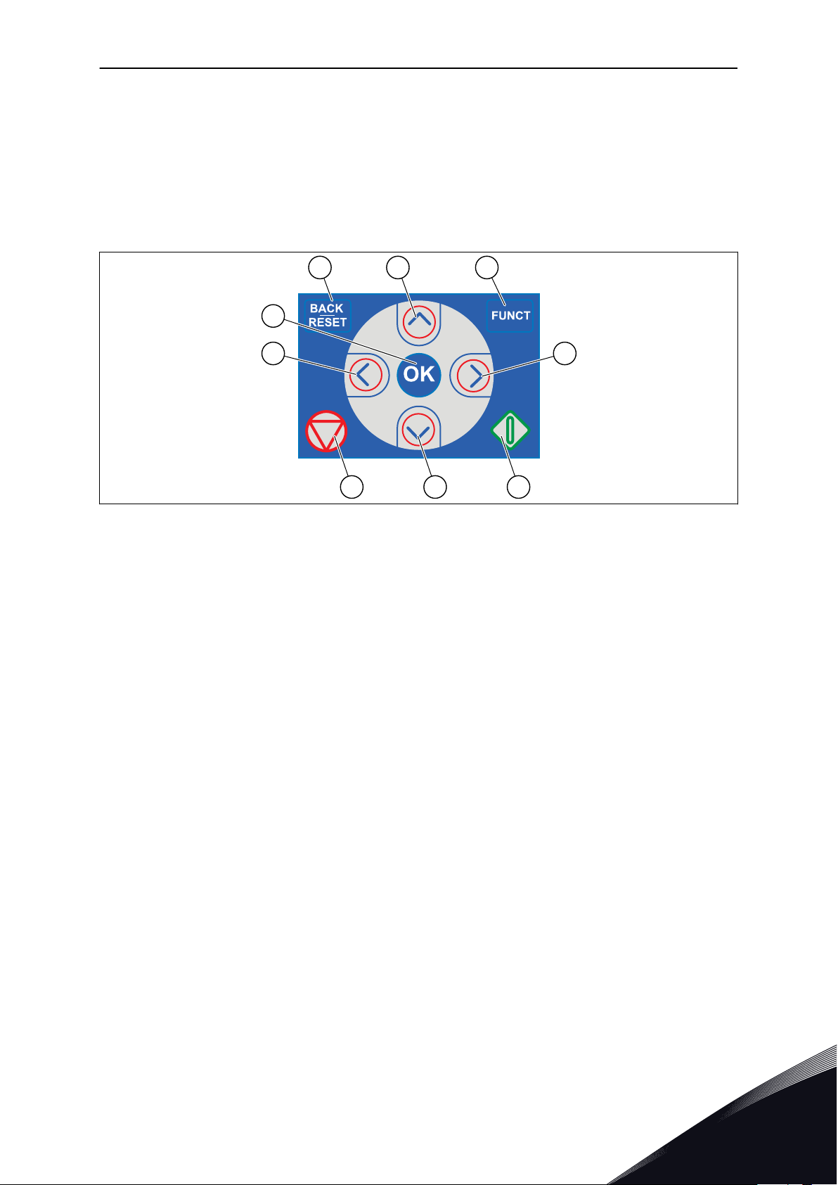
The control panel is the interface between the AC drive and the user. With the control panel,
you can control the speed of a motor and monitor the status of the AC drive. You can also set
the parameters of the AC drive.
Fig. 1: The buttons of the keypad
A. The BACK/RESET button. Use it to move
back in the menu, exit the Edit mode,
reset a fault.
B. The arrow button UP. Use it to scroll the
menu up and to increase a value.
C. The FUNCT button. Use it to change the
rotation direction of the motor, access
the control page, and change the control
place. See more in Table 12 Control
reference settings.
D. The arrow button RIGHT.
E. The START button.
F. The arrow button DOWN. Use it to scroll
the menu down and to decrease a value.
G. The STOP button.
H. The arrow button LEFT. Use it to move
the cursor left.
I. The OK button. Use it to go into an active
level or item, or to accept a selection.
1.2 THE DISPLAYS
There are 2 display types: the graphical display and the text display. The control panel always
has the same keypad and buttons.
The display shows this data.
The status of the motor and the drive.
•
Faults in the motor and in the drive.
•
Your location in the menu structure.
•
24-HOUR SUPPORT +358 (0)201 212 575 · EMAIL: [email protected]
1
Page 12
STOP
READY I/O
Main Menu
A B C D E
F
H
G
Quick Setup
( 17 )
Monitor
( 5 )
Parameters
( 12 )
M1ID:
A B
F
C
D
E
VACON · 12 QUICK STARTUP GUIDE
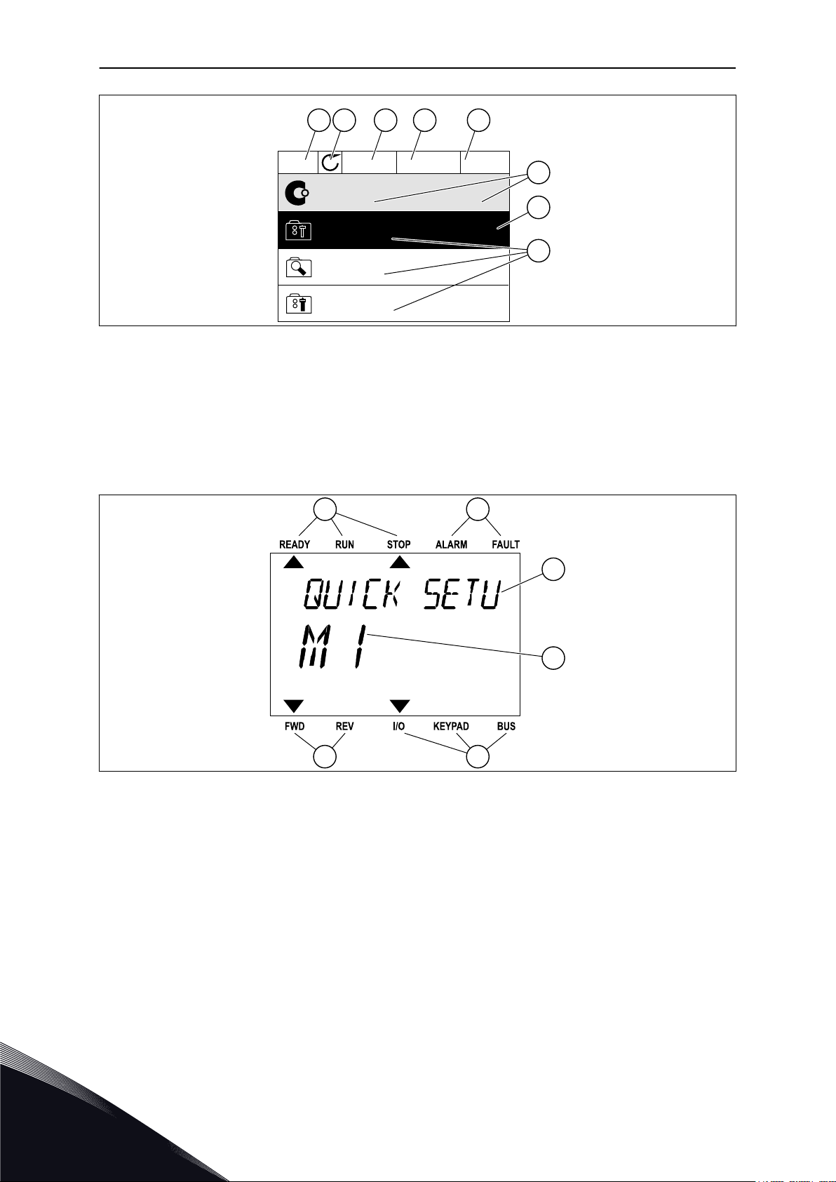
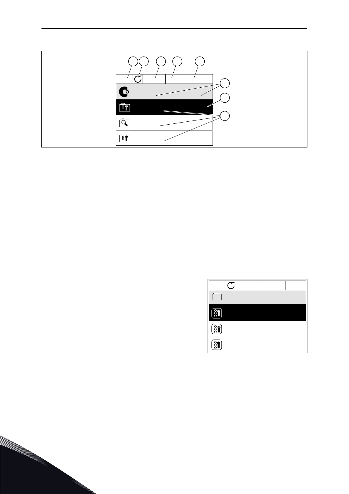
Fig. 2: The graphical display
A. The first status field: STOP/RUN
B. The rotation direction of the motor
C. The second status field: READY/NOT
READY/FAULT
D. The alarm field: ALARM/E. The control place field: PC/IO/KEYPAD/
F. The location field: the ID number of the
parameter and the current location in
the menu
G. An activated group or item
H. The number of items in the group in
question
FIELDBUS
Fig. 3: The text display. If the text is too long to show, the text scrolls automatically on the display.
A. The indicators of status
B. The indicators of alarm and fault
C. The name of the group or item of the
current location
1.3 FIRST START-UP
The Start-up wizard tells you to give necessary data for the drive to control your procedure.
1
D. The current location in the menu
E. The indicators of the control place
F. The indicators of the rotation direction
TEL. +358 (0)201 2121 · FAX +358 (0)201 212 205
Page 13

QUICK STARTUP GUIDE VACON · 13
1
2
3 Time* hh:mm:ss
4 Date* dd.mm.
5 Year* yyyy
Language selection The selection is different in all the language
packages
Daylight saving*
Russia
US
EU
OFF
* If a battery is installed, you see these questions.
Run Startup wizard?
6
Yes
No
To set the parameter values manually, make the selection No and push the OK button.
Make a selection of a process
7
8
9 Set a value for Motor Nominal Current Range: Varies
10 Set a value for Minimum frequency Range: 0.00-50.00
11 Set a value for Maximum frequency Range: 0.00-320.00
Set a value for Motor Nominal Speed (so that it
agrees with the nameplate)
Pump
Fan
Range: 24-19200
After these selections, the Start-up wizard is completed. To start the Start-up wizard again,
you have 2 alternatives. Go to the parameter P6.5.1 Restore Factory Defaults or to the
parameter P1.19 Start-up Wizard. Then set the value to Activate.
1.4 DESCRIPTION OF THE APPLICATIONS
1.4.1 VACON HVAC APPLICATION
The Vacon HVAC drive contains a preloaded application for instant use.
It is possible to control the drive from the keypad, Fieldbus, PC or I/O terminal.
24-HOUR SUPPORT +358 (0)201 212 575 · EMAIL: [email protected]
1
Page 14
+
-
1
6
2
3
4
5
18
19
30
12
7
13
8
9
10
14
15
16
11
17
A
B
mA
AO1-/GND
+24 V
in
24 V
out
GND
GND
DI1
DI2
DI3
DI4
DI5
DI6
CM
CM
RS485
RS485
Standard I/O board
Terminal Signal Description
+10 V
ref
AI1+
AI1-
AI2+
AI2-
24 V
out
Reference output
24 V aux. voltage
I/O ground
Digital input 1
Digital input 2
Digital input 3
Digital input 4
Digital input 5
Digital input 6
Common A for DIN1-DIN6 **)
Common A for DIN1-DIN6 **)
24 V aux. voltage
I/O ground
Analogue signal (+output)
Analogue output common
Output
frequency
Serial bus, negative
Serial bus, positive
Fault
AO1+
Voltage
Current
Start REV
Fault reset
Preset freq select 1
Preset freq select 2
Start FWD
Reference
potentiometer
1-10kΩ
2-wire
transmitter
Remote
reference
4-20mA/2-10V
(programmable)
Analogue input,
voltage or current *)
Analogue input
common (current)
Analogue input,
voltage or current *)
Analogue input
common (current)
24 V auxiliary input voltage
To Relay board 1 or 2
VACON · 14 QUICK STARTUP GUIDE
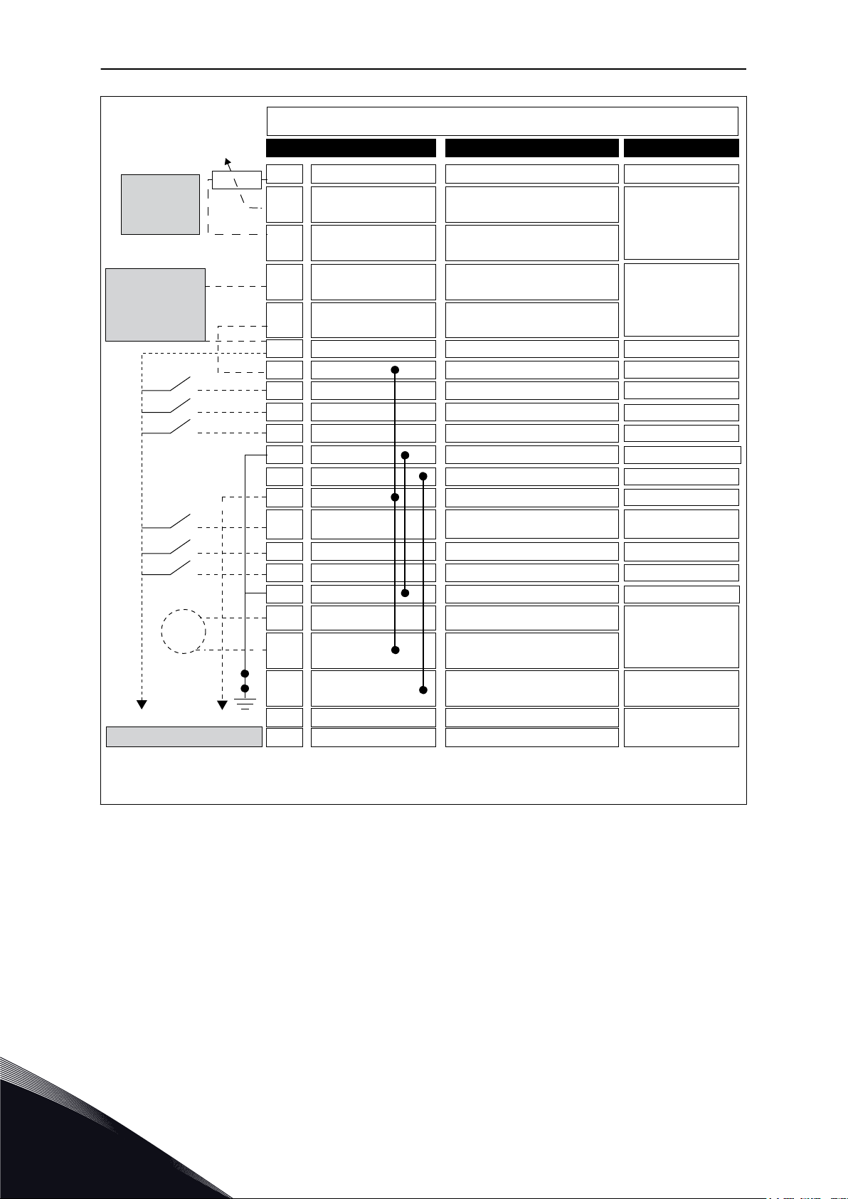
Fig. 4: The control connections example for the standard I/O board
* = You can use DIP switches to select these. See Vacon 100 Installation Manual, Wallmounted Drives.
** = You can isolate the digital inputs from the ground with a DIP switch.
1
TEL. +358 (0)201 2121 · FAX +358 (0)201 212 205
Page 15
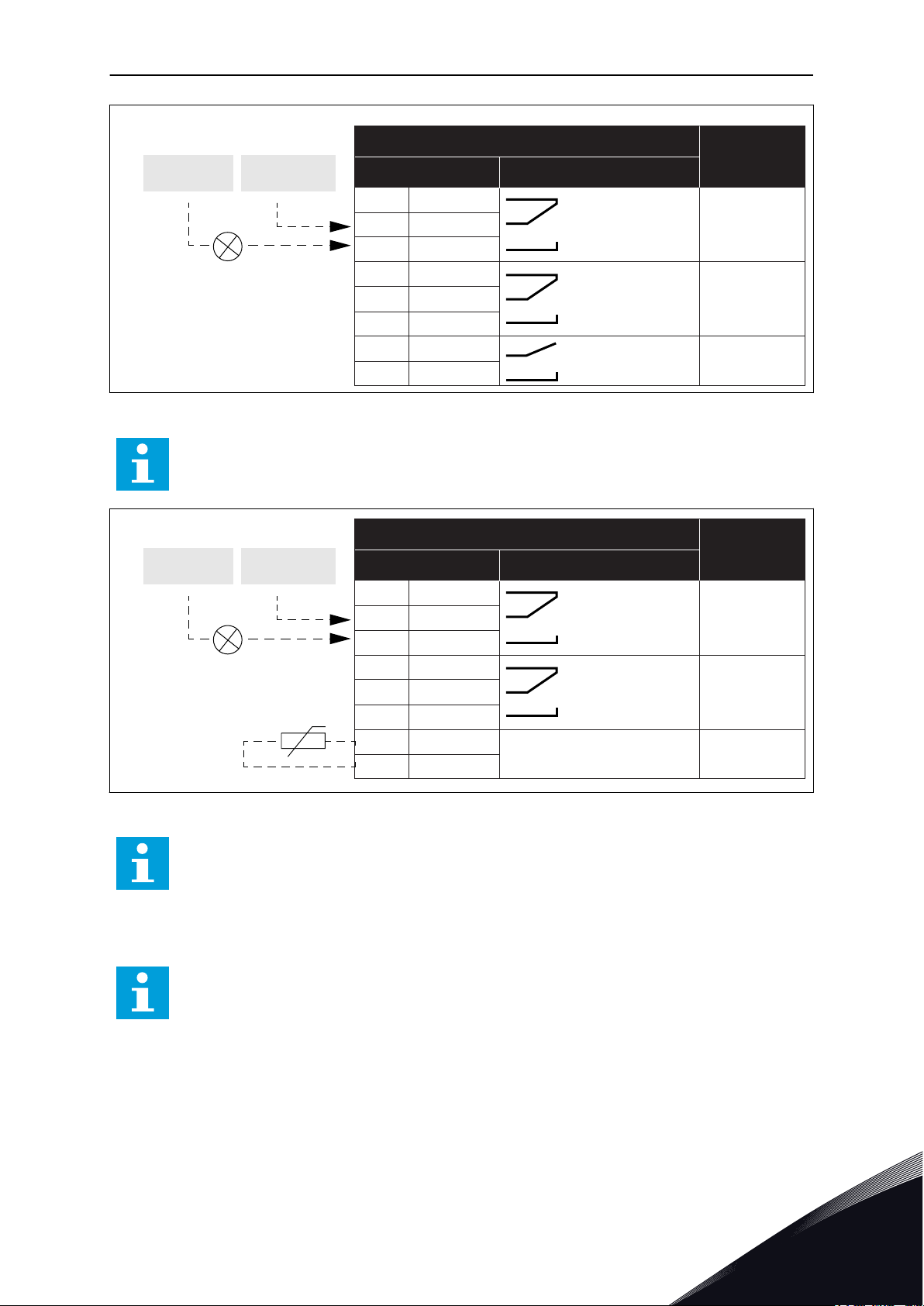
21
22
23
24
25
26
32
33
RUN
RUN
FAULT
READY
Relay output 1
Relay output 2
Relay output 3
From Standard I/O board
Terminal Signal
Default
Relay board 1
From term.
#6 or 12
From term.
#13
RO1/1 NC
RO1/2 CM
RO1/3 NO
RO2/1 NC
RO2/2 CM
RO2/3 NO
RO3/1 CM
RO3/2 NO
TI1+
TI1-
21
22
23
24
25
26
28
29
RUN
RUN
FAULT
Relay output 1
Relay output 2
From Standard I/O board
Terminal Signal
Default
Relay board 2
From term.
#12
From term.
#13
Thermistor input
RO1/1 NC
RO1/2 CM
RO1/3 NO
RO2/1 NC
RO2/2 CM
RO2/3 NO
QUICK STARTUP GUIDE VACON · 15
Fig. 5: The control connection example for the relay board 1
NOTE!
Not available for Vacon 100 X.
Fig. 6: The control connection example for the relay board 2
NOTE!
The only option for Vacon 100 X.
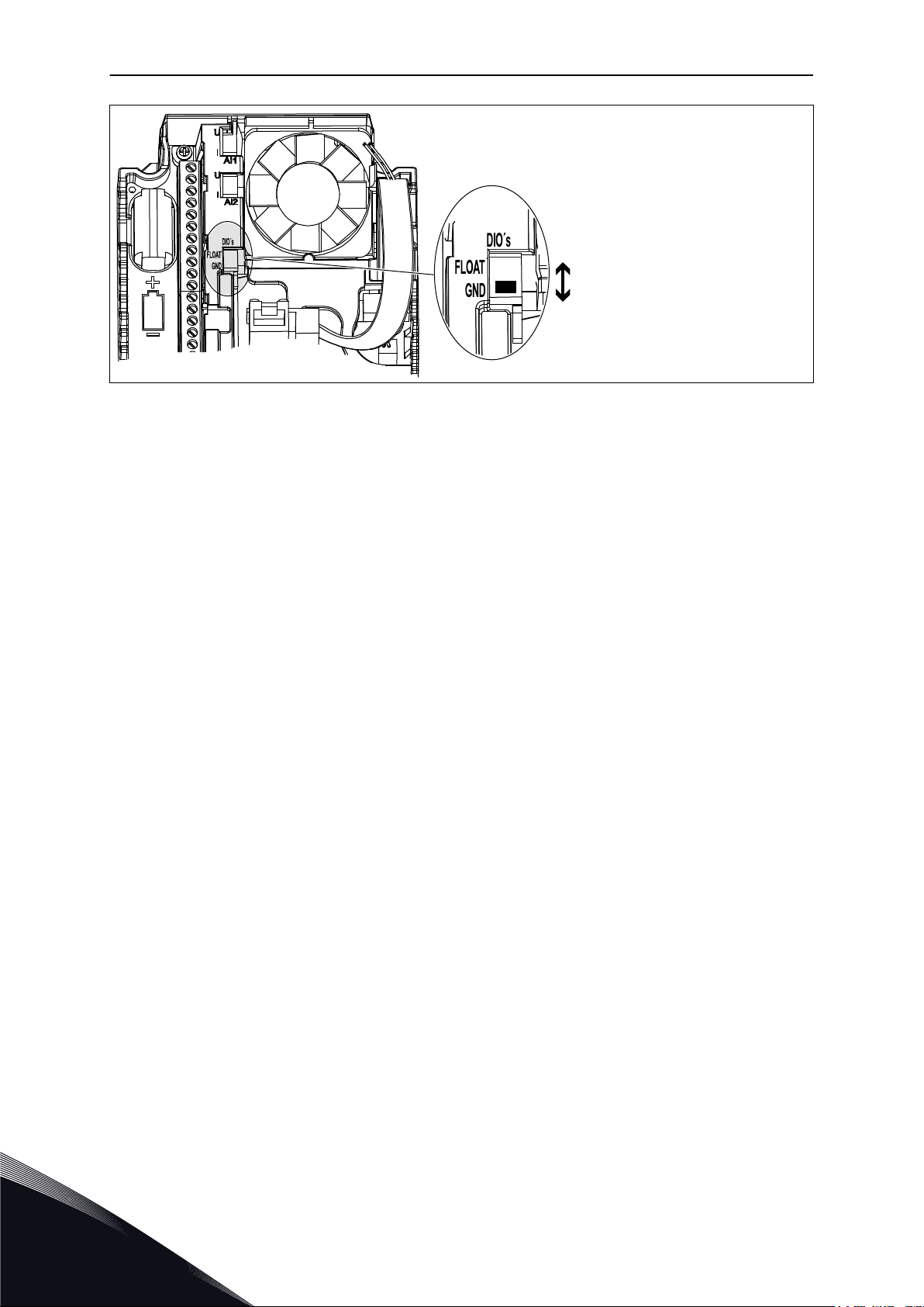
You can also isolate the digital inputs (terminals 8-10 and 14-16) on the standard I/O board
from ground. To do this, set the dip switch on the control board to position OFF. See the
figure below to find the switches and to make applicable selections for your requirements.
NOTE!
For the DIP switch configurations in Vacon 100 X, see the Vacon 100 X Installation
24-HOUR SUPPORT +358 (0)201 212 575 · EMAIL: [email protected]
manual.
1
Page 16
Digital inputs
Floating
Connected to GND
(Default!)
VACON · 16 QUICK STARTUP GUIDE
Fig. 7: The DIP switch
1
TEL. +358 (0)201 2121 · FAX +358 (0)201 212 205
Page 17

QUICK STARTUP GUIDE VACON · 17
Table 2: Quick Setup parameter group
Index Parameter Min Max Unit Default ID Description
Find this value Un on
P1.1
P1.2
Motor Nominal Volt-
age
Motor Nominal Fre-
quency
Varies Varies V Varies 110
8.0 320.0 Hz 50 111
the nameplate of the
motor.
See P3.1.1.1.
Find this value fn on
the nameplate of the
motor.
See P3.1.1.2.
P1.3
P1.4
P1.5 Motor Cos Phi 0.30 1.00 Varies 120
P1.6 Motor nominal power Varies Varies kW Varies 116
P1.7 Motor Current Limit Varies Varies A Varies 107
P1.8 Minimum Frequency 0.00 P1.9 Hz Varies 101
P1.9 Maximum Frequency P1.8 320.00 Hz 50.00 102
Motor Nominal
Speed
Motor Nominal Cur-
rent
24 19200 rpm Varies 112
Varies Varies A Varies 113
Find this value nn on
the nameplate of the
motor.
Find this value In on
the nameplate of the
motor.
Find this value on the
nameplate of the
motor.
Find this value nn on
the nameplate of the
motor.
The maximum motor
current from the AC
drive.
The minimum frequency reference that
is acceptable.
The maximum frequency reference that
is acceptable.
P1.10
P1.11 Preset frequency 1 P3.3.1 300.00 Hz 10.00 105
24-HOUR SUPPORT +358 (0)201 212 575 · EMAIL: [email protected]
I/O Control Refer-
ence A Selection
1 8 6 117
The selection of the
frequency reference
source when the control place is I/O A.
See P3.3.3 for selections.
Select with the digital
input: Preset frequency
selection 0 (P3.5.1.15)
(Default = Digital Input
4)
1
Page 18

VACON · 18 QUICK STARTUP GUIDE
Table 2: Quick Setup parameter group
Index Parameter Min Max Unit Default ID Description
Select with the digital
input: Preset frequency
P1.12 Preset frequency 2 P3.3.1 300.00 Hz 15.00 106
P1.13 Acceleration Time 1 0.1 3000.0 s 20.0 103
P1.14 Deceleration Time 1 0.1 3000.0 s 20.0 104
selection 1 (P3.5.1.16)
(Default = Digital Input
5)
Gives the quantity of
time that is necessary
for the output frequency to increase
from zero frequency to
the maximum frequency.
Gives the quantity of
time that is necessary
for the output frequency to decrease
from the maximum
frequency to zero frequency.
P1.15
P1.16 Automatic Reset 0 1 0 731
P1.17 Thermistor Fault 0 3 0 732
P1.18 PID Mini-Wizard * 0 1 0 1803
Remote Control
Place
1 2 1 172
The selection of the
remote control place
(start/stop).
0 = I/O control
1 = Fieldbus control
0 = Disabled
1 = Enabled
0 = No action
1 = Alarm
2 = Fault (Stop according to stop mode)
3 = Fault (Stop by
coasting)
0 = Inactive
1 = Activate
See
1
P1.19 Multi-pump Wizard * 0 1 0
TEL. +358 (0)201 2121 · FAX +358 (0)201 212 205
0 = Inactive
1 = Activate
See Chapter 2.2 Multi-
pump mini-wizard.
Page 19

QUICK STARTUP GUIDE VACON · 19
Table 2: Quick Setup parameter group
Index Parameter Min Max Unit Default ID Description
0 = Inactive
P1.20 Startup Wizard ** 0 1 0 1171
1 = Activate
See Chapter 1.3 First
start-up.
P1.21 Fire Mode Wizard ** 0 1 0 1672
* = The parameter is only visible on the graphical keypad.
** = The parameter is only visible on the graphical and the text keypad.
0 = Inactive
1 = Activate
24-HOUR SUPPORT +358 (0)201 212 575 · EMAIL: [email protected]
1
Page 20
VACON · 20 WIZARDS
2 WIZARDS
2.1 PID MINI-WIZARD
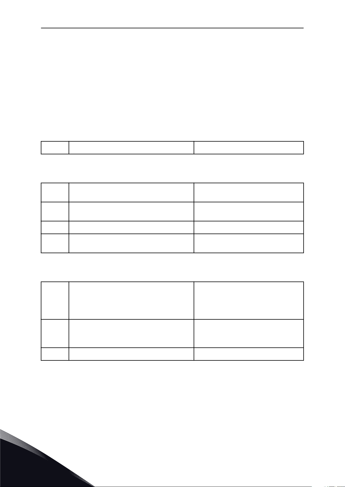
The application wizard helps you to set the basic parameters that are related to the
application.
To start the PID mini-wizard, set the value Activate to parameter P1.17 PID Mini-Wizard in the
Quick Setup menu.
The default settings tell you to use the PID controller in the one feedback / one setpoint
mode. The default control place is I/O A, and the default process unit is %.
1
Make selections for Process unit (P3.12.1.4) More than 1 selection.
If your selection is other than %, you see the next questions. If your selection is %, the wizard
goes directly to question 5.
2
3
4 Set a value for Process Unit Decimals (P3.12.1.7) Range: 0-4
5
Set a value for Process Unit Min (P3.12.1.5) The range depends on the selection in ques-
tion 1.
Set a value for Process Unit Max (P3.12.1.6) The range depends on the selection in ques-
tion 1.
Set a value for Feedback 1 Source Selection
(P3.12.3.3)
See Table 34 Feedback settings
.
If you make a selection of an analogue input signal, you see the question 6. With other
selections, the wizard goes to question 7.
Set the signal range of the analogue input
6
0 = 0-10V / 0…20mA
1 = 2-10V / 4…20mA
See Table 15 Analogue input settings.
Set a value for Error Inversion (P3.12.1.8)
7
8 Set a value for Setpoint Source Selection (P3.12.2.4) See Table 33 Setpoint settings.
0 = Normal
1 = Inverted
If you make a selection of an analogue input signal, you see the question 9. With other
selections, the wizard goes to question 11.
If you set Keypad Setpoint 1 or Keypad Setpoint 2 for the value, the wizard goes directly to
question 10.
2
TEL. +358 (0)201 2121 · FAX +358 (0)201 212 205
Page 21

WIZARDS VACON · 21
Set the signal range of the analogue input
9
0 = 0-10V / 0-20mA
1 = 2-10V / 4-20mA
See Table 15 Analogue input settings.
10
11
Set a value for Keypad Setpoint 1 (P3.12.2.1) and
Keypad Setpoint 2 (P3.12.2.2)
Using the sleep function
Depends on the range set in the question 9.
0 = No
1 = Yes
If you give the value Yes for the question 11, you see the next 3 questions. If you give the value
No, the wizard is completed.
12
13 Set a value for Sleep Delay 1 (P3.12.2.8) Range: 0-3000 s
14 Set a value for Wake-up Level (P3.12.2.9) The range depends on the set process unit
Set a value for Sleep Frequency Limit (P3.12.2.7) Range: 0.00-320.00 Hz
The PID mini-wizard is completed.
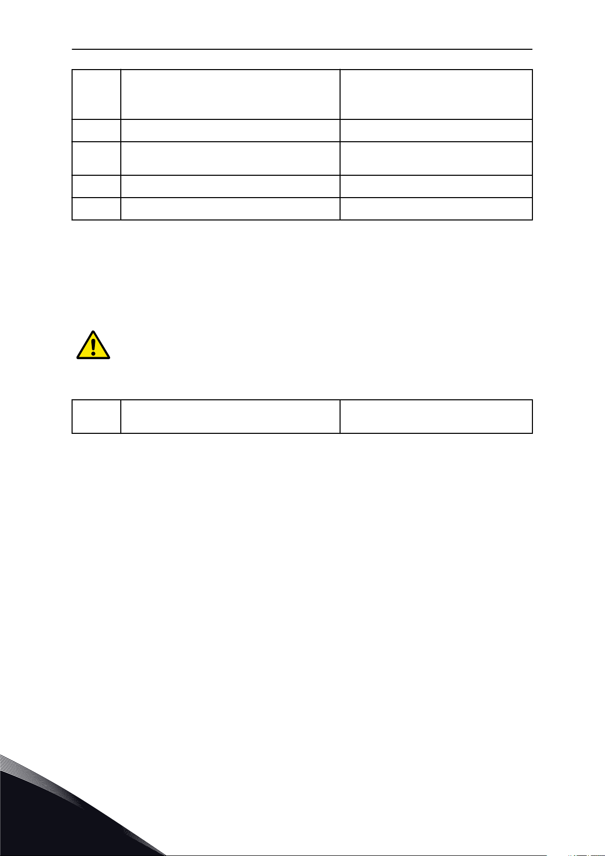
2.2 MULTI-PUMP MINI-WIZARD
The Multi-pump mini-wizard asks the most important questions to set up a Multi-pump
system. The Multi-pump mini-wizard always follows the PID mini-wizard.
15
16
17
Set a value for Number of Motors (P.3.14.1) 1-4
Set a value for Interlock Function (P3.14.2)
0 = Not used
1 = Enabled
Set a value for Autochange (P3.14.4)
0 = Disabled
1 = Enabled
If you enable the Autochange function, you see the next 3 questions. If you do not use the
Autochange function, the wizard goes directly to question 21.
24-HOUR SUPPORT +358 (0)201 212 575 · EMAIL: [email protected]
2
Page 22
VACON · 22 WIZARDS
Set a value for Include FC (P3.14.3)
18
19 Set a value for Autochange Interval (P3.14.5) 0.0-3000.0 h
0 = Disabled
1 = Enabled
20
21 Set a value for Bandwidth (P3.14.8) 0-100%
22 Set a value for Bandwidth Delay (P3.14.9) 0-3600 s
Set a value for Autochange: Frequency Limit
(P3.14.6)
0.00-50.00 Hz
After this, the keypad shows the digital input and relay output configuration done by the
application (graphical keypad only). Write these values down for future reference.
2.3 FIRE MODE WIZARD
To start the Fire Mode Wizard, make the selection Activate for parameter B1.1.4 in the Quick
setup menu.
CAUTION!
Before you continue, read about the password and warranty in Chapter 10.15 Fire
mode.
1
Set a value for parameter P3.17.2 Fire Mode Frequency Source
If you set a value other than Fire mode frequency, the wizard goes directly to question 3.
More than 1 selection
2
TEL. +358 (0)201 2121 · FAX +358 (0)201 212 205
Page 23

WIZARDS VACON · 23
2
3
4
5
6
Set a value for parameter P3.17.3 Fire Mode Frequency
Activate the signal when the contact opens or when
it closes
Set a value for parameters P3.17.4 Fire Mode Activation on OPEN / P3.17.5 Fire Mode Activation on
CLOSE
Set a value for parameter P3.17.6 Fire Mode
Reverse
Set a value for P3.17.1 Fire Mode Password Set a password to enable the Fire mode func-
8.00 Hz...P3.3.1.2 (MaxFreqRef)
0 = Open contact
1 = Closed contact
Make a selection of a digital input to activate
Fire mode. See also Chapter 10.15 Fire mode.
Make a selection of a digital input to activate
the reverse direction in Fire mode.
DigIn Slot0.1 = FORWARD
DigIn Slot0.2 = REVERSE
tion.
1234 = Enable test mode
1001 = Enable Fire mode
24-HOUR SUPPORT +358 (0)201 212 575 · EMAIL: [email protected]
2
Page 24

VACON · 24 USER INTERFACES
3 USER INTERFACES
3.1 NAVIGATION ON THE KEYPAD
The data of the AC drive is in menus and submenus. To move between the menus, use the
arrow buttons Up and Down in the keypad. To go into a group or an item, push the OK button.
To go back to the level where you were before, push the Back/Reset button.
On the display, you see your current location in the menu, for example M5.5.1. You also see
the name of the group or item in your current location.
3
TEL. +358 (0)201 2121 · FAX +358 (0)201 212 205
Page 25
Main menu
Submenus Submenus Submenus
Main menu Main menu
M2 Monitor
M1 Quick
setup
M2.1 Multimonitor
M3.1 Motor Settings
M3.2 Start/Stop Setup
M3.3 References
M3.4 Ramps and Brakes
M3.5 I/O Configuration
M3.6 FB Data Mapping
M3.10 Automatic Reset
M3.11 Timer Functions
M3.18 kWh Pulse Object
M3.12 PID Controller 1
M3.13 PID Controller 2
M3.14 Multi-Pump
M3.16 Fire Mode
M3.17 Appl. Settings
M3.7 Prohibit Freq
M3.8 Limit Supervisions
M3.9 Protections
M2.2 Basic
M2.3
Timer Functions
M2.4
PID Controller 1
M2.5
PID Controller 2
M2.6 Multi-Pump
M2.7 Fieldbus data
M3
Parameters
M4
Diagnostics
M5
I/O and
Hardware
M6 User
Settings
M7
Favourites
M8 User
Levels
M4.2 Reset Faults
M4.3 Fault History
M4.1 Active Faults
M4.5 Total Counters
M4.6 Trip Counters
M4.7 Software Info
M5.1 Basic I/O
M5.2-M5.4 Slot C,D,E
M5.5 Real Time Clock
M5.6 Power unit sett.
M5.7 Keypad
M5.8 RS-485
M5.9 Ethernet
M6.5
Parameter Backup
M6.1 Language
selections
M6.6
Parameter Compare
M6.7 Drive Name
M8.1 User Level
M8.2 Access Code
USER INTERFACES VACON · 25
Fig. 8: The basic menu structure of the AC drive
24-HOUR SUPPORT +358 (0)201 212 575 · EMAIL: [email protected]
3
Page 26
STOP
READY I/O
Main Menu
A B C D E
F
H
G
Quick Setup
( 17 )
Monitor
( 5 )
Parameters
( 12 )
M1ID:
STOP
READY
I/O
Rem Control Place
I/O Control
KeypadStopButton
Yes
Start Function
Ramping
Start / Stop Setup
M3.2.1ID:172
VACON · 26 USER INTERFACES
3.2 USING THE GRAPHICAL DISPLAY
Fig. 9: The main menu of the graphical display
A. The first status field: STOP/RUN
B. The rotation direction
C. The second status field: READY/NOT
READY/FAULT
D. The alarm field: ALARM/E. The control place: PC/IO/KEYPAD/
FIELDBUS
F. The location field: the parameter ID
number and the current location in the
menu
G. An activated group or item: push OK to
go in
H. The number of items in the group in
question
3.2.1 EDITING THE VALUES
On the graphical display, there are 2 different procedures to edit the value of an item.
Usually, you can set only 1 value for a parameter. Select from a list of text values or from a
range of numerical values.
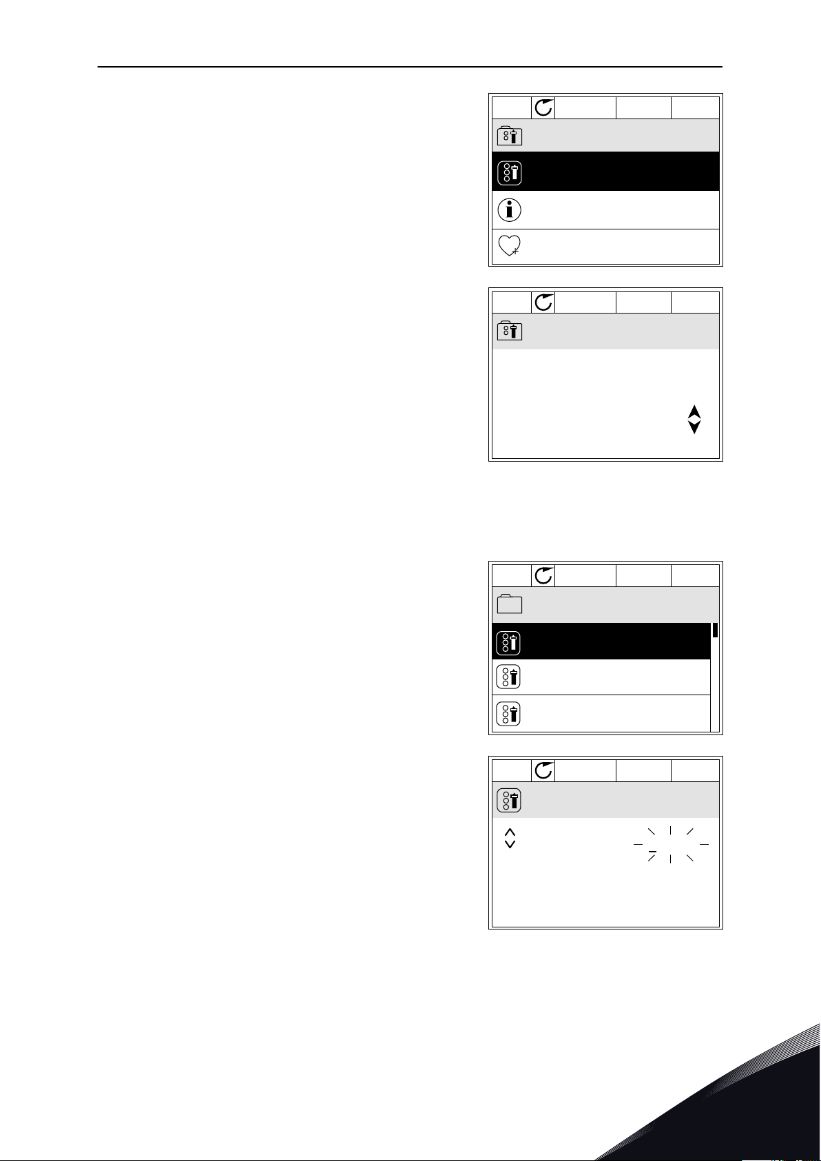
CHANGING THE TEXT VALUE OF A PARAMETER
1 Find the parameter with the arrow buttons.
3
TEL. +358 (0)201 2121 · FAX +358 (0)201 212 205
Page 27
STOP
READY
I/O
Rem Control Place
M3.2.1ID:
Edit
Help
Add to favourites
STOP
READY
I/O
Rem Control Place
M3.2.1ID:
FieldbusCTRL
I/O Control
STOP
READY
I/O
Frequency Ref
P3.3.1.1ID:101
MaxFreqReference
0.00 Hz
MinFreqReference
50.00 Hz
PosFreqRefLimit
320.00 Hz
STOP
READY
I/O
MinFreqReference
P3.3.1.1ID:101
0.00 Hz
Min: 0.00Hz
Max: 50.00Hz
USER INTERFACES VACON · 27
2 To go to the Edit mode, push the OK button 2 times
or push the arrow button Right.
3 To set a new value, push the arrow buttons Up and
Down.
4 To accept the change, push the OK button. To
ignore the change, use the Back/Reset button.
EDITING THE NUMERICAL VALUES
1 Find the parameter with the arrow buttons.
2 Go to the Edit mode.
24-HOUR SUPPORT +358 (0)201 212 575 · EMAIL: [email protected]
3
Page 28
STOP
READY
I/O
MinFreqReference
P3.3.1.1ID:101
00.00 Hz
Min: 0.00Hz
Max: 50.00Hz
STOP
READY
I/O
MinFreqReference
P3.3.1.1ID:101
11.00 Hz
Min: 0.00Hz
Max: 50.00Hz
STOP
READY
I/O
P3.12.1.3ID:1466
Interval 1
00:00:00
00:00:00
ON Time
OFF Time
Days
0
A
VACON · 28 USER INTERFACES
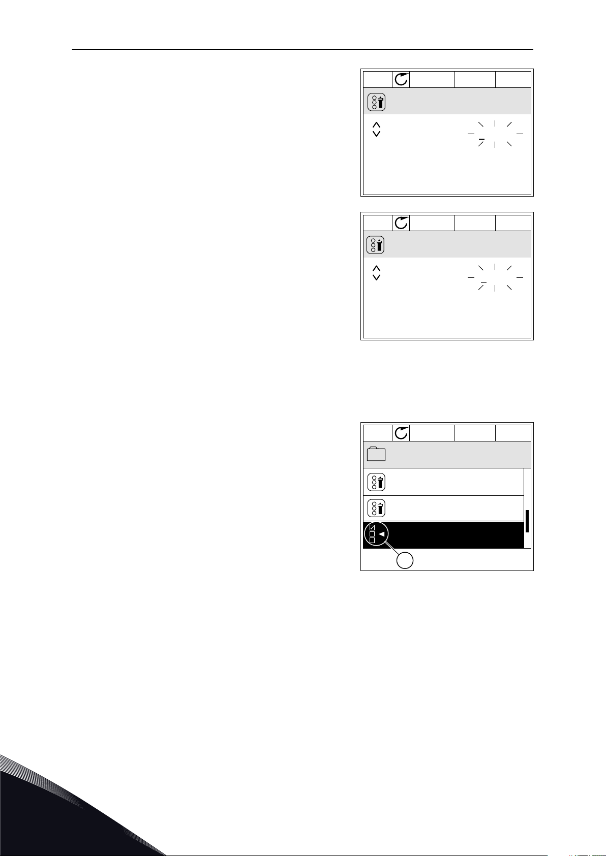
3 If the value is numerical, move from digit to digit
with the arrow buttons Left and Right. Change the
digits with the arrow buttons Up and Down.
4 To accept the change, push the OK button. To
ignore the change, go back to the level where you
were before with the Back/Reset button.
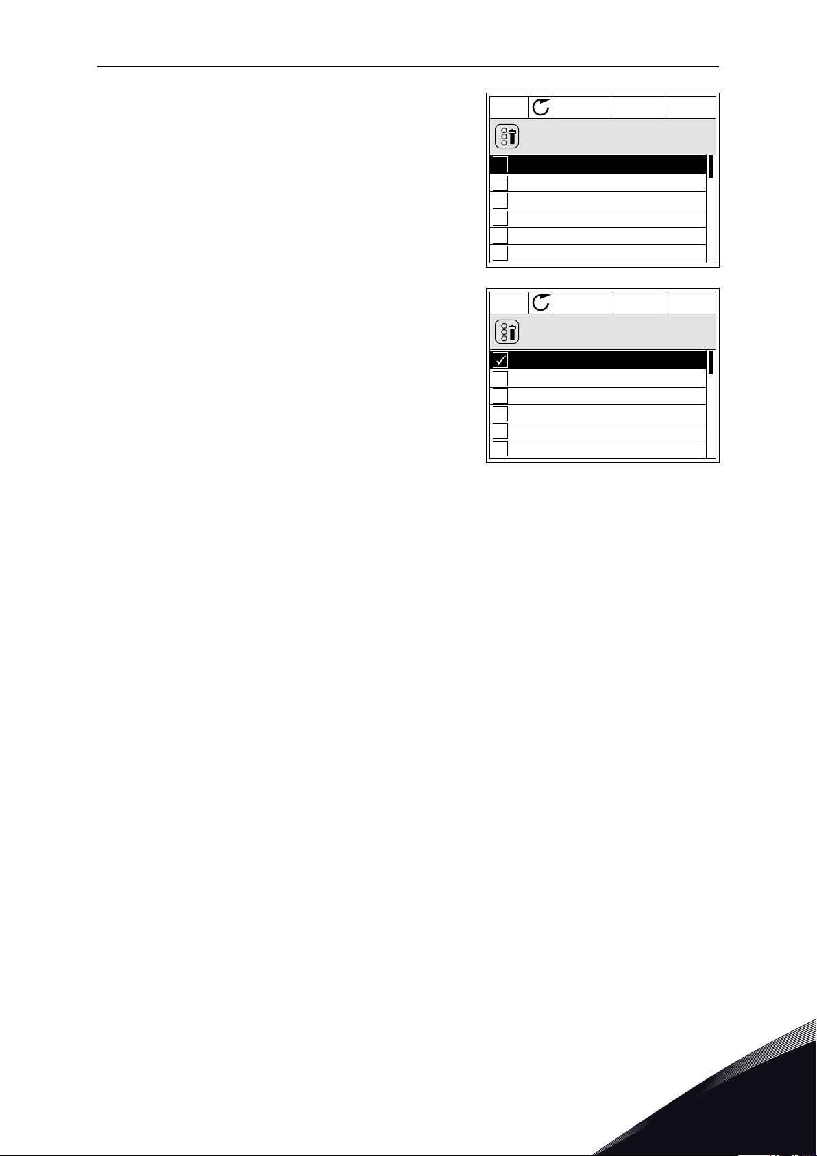
THE SELECTION OF MORE THAN 1 VALUE
Some parameters let you to make a selection of more than 1 value. Select a checkbox at
each necessary value.
1 Find the parameter. There is a symbol on the
display when a checkbox selection is possible.
A. The symbol of the checkbox
selection
3
TEL. +358 (0)201 2121 · FAX +358 (0)201 212 205
Page 29
STOP
READY
I/O
M 3.12.1.3.1ID:
Days
Monday
Tuesday
Wednesday
Thursday
Friday
Sunday
STOP
READY
I/O
M 3.12.1.3.1ID:
Days
Monday
Tuesday
Wednesday
Thursday
Friday
Sunday
USER INTERFACES VACON · 29
2 To move in the list of values, use the arrow buttons
Up and Down.
3 To add a value into your selection, select the box
that is next to it with the arrow button Right.
3.2.2 RESETTING A FAULT
To reset a fault, you can use the Reset button or the parameter Reset Faults. See the
instructions in 11.1 A fault comes into view.
3.2.3 THE FUNCT BUTTON
You can use the Funct button for 3 functions.
To have an access to the Control page.
•
To easily change between the Local and Remote control places.
•
To change the rotation direction.
•
The selection of the control place determines from where the AC drive takes the start and
stop commands. All the control places have a parameter for the selection of the frequency
reference source. The Local control place is always the keypad. The Remote control place is
I/O or Fieldbus. You can see the current control place on the status bar of the display.
It is possible to use I/O A, I/O B and Fieldbus as Remote control places. I/O A and Fieldbus
have the lowest priority. You can make a selection of them with P3.2.1 (Remote Control
Place). I/O B can bypass the Remote control places I/O A and Fieldbus with a digital input.
You can make a selection of the digital input with parameter P3.5.1.5 (I/O B Control Force).
The keypad is always used as a control place when the control place is Local. Local control
has higher priority than Remote control. For example, when you are in Remote control, if
parameter P3.5.1.5 bypasses the control place with a digital input, and you make a selection
of Local, Keypad becomes the control place. Use the Funct button or P3.2.2 Local/Remote to
change between the Local and Remote control.
24-HOUR SUPPORT +358 (0)201 212 575 · EMAIL: [email protected]
3
Page 30
STOP
READY Keypad
ID: M1
Main Menu
Monitor
( 12 )
( 21 )
( 6 )
Parameters
Diagnostics
STOP
READY Keypad
ID:1805
Choose action
Control page
Change direction
Local/Remote
STOP
READY Keypad
ID:211
Local/Remote
Remote
Local
STOP
READY I/O
ID: M1
Main Menu
( 21 )
( 6 )
Parameters
( 12 )
Monitor
Diagnostics
VACON · 30 USER INTERFACES
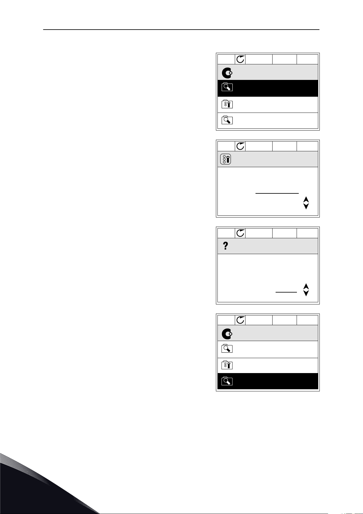
CHANGING THE CONTROL PLACE
1 Anywhere in the menu structure, push the Funct
button.
2 To make a selection of the Local/Remote, use the
arrow buttons Up and Down. Push the OK button.
3 To make a selection of Local or Remote, use the
arrow buttons Up and Down again. To accept the
selection, push the OK button.
4 If you changed Remote control place to Local, that
is, the keypad, give a keypad reference.
After the selection, the display goes back into the same location where it was when you
pushed the Funct button.
3
TEL. +358 (0)201 2121 · FAX +358 (0)201 212 205
Page 31

STOP
READY I/O
Main Menu
( 21 )
( 6 )
Parameters
( 12 )
Monitor
Diagnostics
M1ID:
STOP
READY Keypad
ID:1805
Choose action
Control page
Change direction
Local/Remote
STOP
READY Keypad
ID: 184
Keypad Reference
0.00Hz
Output Frequency
Motor Current
Motor Torque
Motor Power
0.00Hz
0.00A
0.00%
0.00%
STOP
READY Keypad
ID: 168
Keypad Reference
0.00Hz
Output Frequency
Motor Current
Motor Torque
Motor Power
0.00Hz
0.00A
0.00%
0.00%
USER INTERFACES VACON · 31
GOING INTO THE CONTROL PAGE
It is easy to monitor the most important values in the Control page.
1 Anywhere in the menu structure, push the Funct
button.
2 To make a selection of the Control page, push the
arrow buttons Up and Down. Go in with the OK
button. The control page opens.
3 If you use the Local control place and the keypad
reference, you can set P3.3.6 Keypad Reference
with the OK button.
4 To change the digits in the value, push the arrow
buttons Up and Down. Accept the change with the
OK button.
See more information about Keypad Reference in Chapter 5.3 Group 3.3: Control reference
settings. If you use other control places or reference values, the display shows the frequency
reference, which you cannot edit. The other values on the page are Multimonitoring values.
24-HOUR SUPPORT +358 (0)201 212 575 · EMAIL: [email protected]
3
Page 32

STOP
READY I/O
ID: M1
Main Menu
Monitor
( 7 )
Parameters
( 15 )
Diagnostics
( 6 )
RUN
READY Keypad
ID:1805
Choose action
Control page
Change direction
Local/Remote
RUN
READY Keypad
ID:1805
Choose action
Forward
Reverse
VACON · 32 USER INTERFACES
You can make a selection of the values that show up here (see instructions in Chapter 4.1.1
Multimonitor).
CHANGING THE ROTATION DIRECTION
You can change the rotation direction of the motor quickly with the Funct button.
NOTE!
The command Change direction is available in the menu only if the current control
place is Local.
1 Anywhere in the menu structure, push the Funct
button.
2 To make a selection of the Change direction, push
the arrow buttons Up and Down. Push the OK
button.
3 Make a selection of a new rotation direction. The
current rotation direction blinks. Push the OK
button.
3
TEL. +358 (0)201 2121 · FAX +358 (0)201 212 205
Page 33

STOP
READY I/O
ID: M1
Main Menu
Monitor
( 7 )
Parameters
( 15 )
Diagnostics
( 6 )
STOP
READY Keypad
ID: M6
Main Menu
I/O and Hardware
( 9 )
User settings
( 4 )
Favourites
( 0 )
USER INTERFACES VACON · 33
4 The rotation direction changes immediately. You
can see that the arrow indication in the status field
of the display changes.
3.2.4 COPYING THE PARAMETERS
NOTE!
This function is available only in the graphical display.
Before you can copy parameters from the control panel to the drive, you must stop the drive.
COPYING THE PARAMETERS OF AN AC DRIVE
Use this function to copy parameters from a drive to another.
1 Save the parameters to the control panel.
2 Detach the control panel and connect it to another
drive.
3 Download the parameters to the new drive with the
command Restore from keypad.
SAVING THE PARAMETERS TO THE CONTROL PANEL
1 Go into the User settings menu.
24-HOUR SUPPORT +358 (0)201 212 575 · EMAIL: [email protected]
3
Page 34

STOP
READY Keypad
ID: M6.5
User settings
Language selection
English
Parameter backup
( 7 )
Drive name
Drive
STOP
READY Keypad
ID: M6.5.1
Parameter backup
Restore factory defaults
Save to keypad
Restore from keypad
VACON · 34 USER INTERFACES
2 Go into the Parameter backup submenu.
3 Use the arrow buttons Up and Down to make a
selection of a function. Accept the selection with
the OK button.
The command Restore factory defaults brings back the parameter settings that were made
at the factory. With the command Save to keypad you can copy all the parameters to the
control panel. The command Restore from keypad copies all the parameters from the
control panel to the drive.
The parameters that you cannot copy if the drives have a different size
If you replace the control panel of a drive with a control panel from a drive that is of a
different size, the values of these parameters do not change.
Motor nominal voltage (P3.1.1.1)
•
Motor nominal frequency (P3.1.1.2)
•
Motor nominal speed (P3.1.1.3)
•
Motor nominal current (P3.1.1.4)
•
Motor cos phii (P3.1.1.5)
•
Motor nominal power (P3.1.1.6)
•
Motor current limit (P3.1.1.7)
•
Switching frequency (P3.1.2.1)
•
Zero frequency voltage (P3.1.2.4)
•
Motor preheat current (P3.1.2.7)
•
Stator voltage adjust (P3.1.2.17)
•
Maximum frequency (P3.3.2)
•
Start magnetizing current (P3.4.8)
•
DC brake current (P3.4.10)
•
Flux braking current (P3.4.13)
•
Stall current limit (P3.9.5)
•
Motor thermal time constant (P3.9.9)
•
3
TEL. +358 (0)201 2121 · FAX +358 (0)201 212 205
Page 35

STOP
READY I/O
ID: M6.6
User Settings
Language Selection
Parameter Backup
Parameter Compare
English
(4)
(7)
STOP
READY I/O
ID: B6.6.1
Parameter Compare
Active set-Set 1
Active set-Set 2
Active set-Defaults
STOP
READY I/O
ID: M6.6.1
Active set-Set 1
Active
Help
Add to Favourites
USER INTERFACES VACON · 35
3.2.5 COMPARING THE PARAMETERS
With this function, you can compare the current parameter set with 1 of these 4 sets.
Set 1 (P6.5.4 Save to Set 1)
•
Set 2 (P6.5.6 Save to Set 2)
•
The defaults (P6.5.1 Restore Factory Defaults)
•
The keypad set (P6.5.2 Save to Keypad)
•
See more about these parameters in Table 57 The parameter compare.
NOTE!
If you have not saved the parameter set with which you want to compare the
current set, the display shows the text Comparing failed.
USING THE FUNCTION PARAMETER COMPARE
1 Go into Parameter Compare in the User settings
menu.
2 Make a selection of the pair of sets. Push OK to
accept the selection.
3 Make a selection of Active and push OK.
24-HOUR SUPPORT +358 (0)201 212 575 · EMAIL: [email protected]
3
Page 36

STOP
READY I/O
ID:113
Active set-Set 1
Motor Nom Currnt
Motor Cos Phi
0.56A
1.90A
0.68
1.74
A B C D
STOP
READY I/O
ID:403 M3.5.1.1
Digital Inputs
Ctrl Signal 1 A
Ctrl Signal 2 A
Ctrl Signal 1 B
STOP
READY I/O
ID:403 M3.5.1.1
Ctrl signal 1 A
Edit
Help
Add to favourites
VACON · 36 USER INTERFACES
4 Examine the comparing between the current values
and the values of the other set.
A. The current value
B. The value of the other set
C. The current value
D. The value of the other set
3.2.6 HELP TEXTS
The graphical display can show help texts on many topics. All the parameters have a help
text.
The help texts are also available for the faults, alarms, and the Startup wizard.
READING A HELP TEXT
1 Find the item about which you want to read.
2 Use the arrow buttons Up and Down to make a
selection of Help.
3
TEL. +358 (0)201 2121 · FAX +358 (0)201 212 205
Page 37

STOP
READY I/O
ID:403 M3.5.1.1
Ctrl signal 1 A
Start Signal 1 for control Place
I/O A. Start Signal 1
functionality chosen with I/O A
Logic in Start/Stop Setup Menu.
A B
F
C
D
E
USER INTERFACES VACON · 37
3 To open the help text, push the OK button.
NOTE!
The help texts are always in English.
3.2.7 USING THE FAVOURITES MENU
If you use the same items frequently, you can add them into Favourites. You can collect a set
of parameters or monitoring signals from all the keypad menus.
See more about how to use the Favourites menu in Chapter 8.2 Favourites.
3.3 USING THE TEXT DISPLAY
You can also have the control panel with the text display for your user interface. The text
display and the graphical display have almost the same functions. Some functions are only
available in the graphical display.
The display shows the status of the motor and the AC drive. It also shows faults in the
operation of the motor and the drive. On the display, you see your current location in the
menu. You also see the name of the group or item in your current location. If the text is too
long for the display, the text scrolls to show the full text string.
Fig. 10: The main menu of the text display
A. The indicators of status
B. The indicators of alarm and fault
24-HOUR SUPPORT +358 (0)201 212 575 · EMAIL: [email protected]
C. The name of the group or item of the
current location
3
Page 38

READY
FAULT
ALARM
STOP
RUN
BUS
KEYPAD
I/O
REV
FWD
READY
FAULT
ALARM
STOP
RUN
BUS
KEYPAD
I/O
REV
FWD
READY
FAULT
ALARM
STOP
RUN
KEYPAD
I/O
REV
FWD
BUS
VACON · 38 USER INTERFACES
D. The current location in the menu
E. The indicators of the control place
3.3.1 EDITING THE VALUES
CHANGING THE TEXT VALUE OF A PARAMETER
Set the value of a parameter with this procedure.
1 Find the parameter with the arrow buttons.
2 To go to the Edit mode, push the OK button.
F. The indicators of the rotation direction
3 To set a new value, push the arrow buttons Up and
Down.
4 Accept the change with the OK button. To ignore
the change, go back to the level where you were
before with the Back/Reset button.
EDITING THE NUMERICAL VALUES
1 Find the parameter with the arrow buttons.
2 Go to the Edit mode.
3
TEL. +358 (0)201 2121 · FAX +358 (0)201 212 205
Page 39

READY
FAULT
ALARM
STOP
RUN
KEYPAD
I/O
REV
FWD
BUS
USER INTERFACES VACON · 39
3 Move from digit to digit with the arrow buttons Left
and Right. Change the digits with the arrow buttons
Up and Down.
4 Accept the change with the OK button. To ignore
the change, go back to the level where you were
before with the Back/Reset button.
3.3.2 RESETTING A FAULT
To reset a fault, you can use the Reset button or the parameter Reset Faults. See the
instructions in 11.1 A fault comes into view.
3.3.3 THE FUNCT BUTTON
You can use the Funct button for 3 functions.
To have an access to the Control page.
•
To easily change between the Local and Remote control places.
•
To change the rotation direction.
•
The selection of the control place determines from where the AC drive takes the start and
stop commands. All the control places have a parameter for the selection of the frequency
reference source. The Local control place is always the keypad. The Remote control place is
I/O or Fieldbus. You can see the current control place on the status bar of the display.
It is possible to use I/O A, I/O B and Fieldbus as Remote control places. I/O A and Fieldbus
have the lowest priority. You can make a selection of them with P3.2.1 (Remote Control
Place). I/O B can bypass the Remote control places I/O A and Fieldbus with a digital input.
You can make a selection of the digital input with parameter P3.5.1.5 (I/O B Control Force).
The keypad is always used as a control place when the control place is Local. Local control
has higher priority than Remote control. For example, when you are in Remote control, if
parameter P3.5.1.5 bypasses the control place with a digital input, and you make a selection
of Local, Keypad becomes the control place. Use the Funct button or P3.2.2 Local/Remote to
change between the Local and Remote control.
CHANGING THE CONTROL PLACE
1 Anywhere in the menu structure, push the Funct
button.
24-HOUR SUPPORT +358 (0)201 212 575 · EMAIL: [email protected]
3
Page 40

READY
FAULT
ALARM
STOP
RUN
KEYPAD
I/O
REV
FWD
BUS
READY
FAULT
ALARM
STOP
RUN
KEYPAD
I/O
REV
FWD
BUS
READY
FAULT
ALARM
STOP
RUN
KEYPAD
I/O
REV
FWD
BUS
VACON · 40 USER INTERFACES
2 To make a selection of the Local/Remote, use the
arrow buttons Up and Down. Push the OK button.
3 To make a selection of Local or Remote, use the
arrow buttons Up and Down again. To accept the
selection, push the OK button.
4 If you changed Remote control place to Local, that
is, the keypad, give a keypad reference.
After the selection, the display goes back into the same location where it was when you
pushed the Funct button.
GOING INTO THE CONTROL PAGE
It is easy to monitor the most important values in the Control page.
1 Anywhere in the menu structure, push the Funct
button.
3
TEL. +358 (0)201 2121 · FAX +358 (0)201 212 205
Page 41

READY
FAULT
ALARM
STOP
RUN
KEYPAD
I/O
REV
FWD
BUS
READY
FAULT
ALARM
STOP
RUN
KEYPAD
I/O
REV
FWD
BUS
USER INTERFACES VACON · 41
2 To make a selection of the Control page, push the
arrow buttons Up and Down. Go in with the OK
button. The control page opens.
3 If you use the Local control place and the keypad
reference, you can set P3.3.6 Keypad Reference
with the OK button.
See more information about the Keypad Reference in Chapter 5.3 Group 3.3: Control
reference settings). If you use other control places or reference values, the display shows the
frequency reference, which you cannot edit. The other values on the page are
Multimonitoring values. You can make a selection of the values that show up here (see
instructions in Chapter 4.1.1 Multimonitor).
CHANGING THE ROTATION DIRECTION
You can change the rotation direction of the motor quickly with the Funct button.
NOTE!
The command Change direction is available in the menu only if the current control
place is Local.
1 Anywhere in the menu structure, push the Funct
button.
2 To make a selection of the Change direction, push
the arrow buttons Up and Down. Push the OK
button.
3 Make a selection of a new rotation direction. The
current rotation direction blinks. Push the OK
button. The rotation direction changes immediately,
and the arrow indication in the status field of the
display changes.
24-HOUR SUPPORT +358 (0)201 212 575 · EMAIL: [email protected]
3
Page 42

VACON · 42 USER INTERFACES
3.4 MENU STRUCTURE
Menu Function
Quick setup See Chapter 1.4.1 Vacon HVAC application.
Monitor Multi-monitor *
Basic
Timer functions
PID controller 1
PID controller 2
Multi-Pump
Fieldbus data
Temperature inputs **
Parameters See Chapter 5 Parameters menu.
Diagnostics Active faults
Reset faults
Fault history
Total counters
Trip counters
Software info
I/O and hardware Basic I/O
Slot C
Slot D
Slot E
Real time clock
Power unit settings
Keypad
RS-485
3
Ethernet
TEL. +358 (0)201 2121 · FAX +358 (0)201 212 205
Page 43

USER INTERFACES VACON · 43
Menu Function
User settings Language selections
Application selection
Parameter backup *
Drive name
Favourites * See Chapter 8.2 Favourites.
User levels See Chapter 8.3 User levels.
* = The function is not available in the control panel with a text display.
** = The function is only available when the OPT-88 or OPT-BH option board is connected to
the AC drive.
3.4.1 QUICK SETUP
The Quick Setup Menu includes the minimum set of the most commonly used parameters
during installation and commissioning of the Vacon 100 HVAC Application. They are collected
in the first parameter group so that they are fast and easy to find. You can also find and edit
them in their actual parameter groups. When you change a parameter value in the Quick
setup group, also the value of this parameter in its actual group changes. More detailed
information on the parameters of this group you will find in chapter 1.3 First start-up and 2
Wizards.
3.4.2 MONITOR
MULTIMONITOR
With the Multimonitor function, you can collect 4-9 items to monitor. See Chapter 4.1.1
Multimonitor.
24-HOUR SUPPORT +358 (0)201 212 575 · EMAIL: [email protected]
3
Page 44

VACON · 44 USER INTERFACES
NOTE!
The Multimonitor menu is not available in the text display.
BASIC
The basic monitoring values can include statuses, measurements, and the actual values of
parameters and signals. See Chapter 4.1.2 Basic.
TIMER FUNCTIONS
With this function, you can monitor the timer functions and the Real Time Clock. See Chapter
4.1.3 Timer functions monitoring.
PID CONTROLLER 1
With this function, you can monitor the PID controller values. See Chapter 4.1.4 PID1
controller monitoring.
PID CONTROLLER 2
With this function, you can monitor the PID controller values. See Chapter 4.1.5 PID2
controller monitoring.
MULTI-PUMP
Use this function to monitor the values that are related to the operation of more than 1 drive.
See Chapter 4.1.6 Multi-pump monitoring.
FIELDBUS DATA
With this function, you see the fieldbus data as monitor values. Use this function, for
example, for monitoring during the fieldbus commissioning. See Chapter 4.1.7 Fieldbus
process data monitoring.
3.5 VACON LIVE
Vacon Live is a PC tool for commissioning and maintenance of the Vacon® 10, Vacon® 20, and
Vacon® 100 AC drives). You can download Vacon Live from http://drives.danfoss.com.
The Vacon Live PC tool includes these functions.
Parametrisation, monitoring, drive info, data logger, etc.
•
The software download tool Vacon Loader
•
Serial communication and Ethernet support
•
Windows XP, Vista 7 and 8 support
•
17 languages: English, German, Spanish, Finnish, French, Italian, Russian, Swedish,
•
Chinese, Czech, Danish, Dutch, Polish, Portuguese, Romanian, Slovak and Turkish
You can make the connection between the AC drive and the PC tool with the Vacon serial
communication cable. The serial communication drivers are installed automatically during
the installation of Vacon Live. After you installed the cable, Vacon Live finds the connected
drive automatically.
3
TEL. +358 (0)201 2121 · FAX +358 (0)201 212 205
Page 45

USER INTERFACES VACON · 45
See more on how to use Vacon Live in the help menu of the program.
Fig. 11: The Vacon Live PC tool
24-HOUR SUPPORT +358 (0)201 212 575 · EMAIL: [email protected]
3
Page 46

STOP
READY I/O
ID: M1
Main Menu
Monitor
(12)
Quick Setup
(4)
Parameters
(21)
STOP
READY I/O
ID: M2.1
Monitor
Multimonitor
Timer Functions
Basic
(13)
(7)
STOP
READY I/O
ID:25 FreqReference
Multimonitor
20.0 Hz
Motor Curre
0.00A
DC-link volt
0.0V
Output Freq
0.00 Hz
Motor Speed
0.0 rpm
Motor Voltage
0.0V
Motor Tempera
0.0%
Motor Torque
0.00 %
Unit Tempera
81.9°C
FreqReference
VACON · 46 MONITORING MENU
4 MONITORING MENU
4.1 MONITOR GROUP
You can monitor the actual values of the parameters and signals. You can also monitor the
statuses and measurements. You can customise some of the values that you can monitor.
4.1.1 MULTIMONITOR
On the Multimonitor page, you can collect 9 items to monitor.
CHANGING THE ITEMS TO MONITOR
1 Go into the Monitor menu with the OK button.
2 Go into Multimonitor.
3 To replace an old item, activate it. Use the arrow
buttons.
4
TEL. +358 (0)201 2121 · FAX +358 (0)201 212 205
Page 47

STOP
READY I/O
ID:1 M2.1.1.1
FreqReference
0.00 %Motor Power
Output frequency
FreqReference
Motor Speed
Motor Current
Motor Torque
0.00 Hz
10.00 Hz
0.00 rpm
0.00 A
0.00 %
MONITORING MENU VACON · 47
4 To make a selection of a new item in the list, push
OK.
4.1.2 BASIC
The basic monitoring values are the actual values of selected parameters, signals, statuses
and measurements. The different applications may have different number of monitoring
values.
You can see the basic monitoring values and their related data in the next table.
NOTE!
Only the standard I/O board statuses are available in the Monitor menu. You can
find the statuses of all the I/O board signals as raw data in the I/O and Hardware
system menu.
Do a check of the statuses of the expander I/O board in the I/O and Hardware system menu
when the system asks you to do it.
24-HOUR SUPPORT +358 (0)201 212 575 · EMAIL: [email protected]
4
Page 48

VACON · 48 MONITORING MENU
Table 3: Items in the monitoring menu
Index Monitoring value Unit ID Description
V2.2.1 Output frequency Hz 1
V2.2.2 Frequency reference Hz 25
V2.2.3 Motor speed rpm 2
V2.2.4 Motor current A 3
V2.2.5 Motor torque % 4
V2.2.7 Motor shaft power % 5
V2.2.8 Motor shaft power kW/hp 73
V2.2.9 Motor voltage V 6
V2.2.10 DC link voltage V 7
V2.2.11 Unit temperature °C 8
V2.2.12 Motor temperature % 9
V2.2.13 Analogue input 1 % 59
V2.2.14 Analogue input 2 % 60
V2.2.15 Analogue output 1 % 81
V2.2.16 Motor Preheat 1228
V2.2.17 Drive Status Word 43
V2.2.19 Fire mode status 1597
V2.2.20 DIN Status Word 1 56
0 = OFF
1 = Heating (feeding DC-current)
B1 = Ready
B2 = Run
B3 = Fault
B6 = RunEnable
B7 = AlarmActive
B10 = DC Current in stop
B11 = DC Brake Active
B12 = RunRequest
B13 = MotorRegulatorActive
0 = Disabled
1 = Enabled
2 = Activated
3 = Test mode
4
V2.2.21 DIN Status Word 2 57
V2.2.22
Motor current with 1
decimal
45
TEL. +358 (0)201 2121 · FAX +358 (0)201 212 205
Page 49

MONITORING MENU VACON · 49
Table 3: Items in the monitoring menu
Index Monitoring value Unit ID Description
B0 = Interlock1
B1 = Interlock2, B5 = I/O A Control Act.
B6 = I/O B Control Act.
B7 = Fieldbus Control Act.
V2.2.23 Appl.StatusWord 1 89
B8 = Local Control Act.
B9 = PC Control Act.
B10 = Preset Frequencies Act.
B12 = FireMode Act.
B13 = PreHeat Act.
V2.2.24 Appl.StatusWord 2 90
V2.2.25
V2.2.26
V2.2.27 LastActiveFaultCode 37
V2.2.28 LastActiveFault ID 95
V2.2.29
V2.2.30 LastActiveAlarm ID 94
V2.2.31 U Phase Current A 39
V2.2.32 V Phase Current A 40
V2.2.33 W Phase Current A 41
V2.2.34 MotorRegulat.Status 77
kWhTripCounter
Low
kWhTripCounter
High
LastActiveAlarm-
Code
1054
1067
74
B0 = Acc/Dec Prohibited
B1 = MotorSwitch Act.
B0: Current limit (Motor)
B1: Current limit (Generator)
B2: Torque limit (Motor)
B3: Torque limit (Generator)
B4: Overvoltage control
B5: Undervoltage control
B6: Power limit (Motor)
B7: Power limit (Generator)
4.1.3 TIMER FUNCTIONS MONITORING
Monitor the values of Timer functions and the Real Time Clock.
24-HOUR SUPPORT +358 (0)201 212 575 · EMAIL: [email protected]
4
Page 50

VACON · 50 MONITORING MENU
Table 4: Monitoring of the timer functions
Index Monitoring value Unit ID Description
V2.3.1 TC 1, TC 2, TC 3 1441
V2.3.2 Interval 1 1442
V2.3.3 Interval 2 1443
V2.3.4 Interval 3 1444
V2.3.5 Interval 4 1445
V2.3.6 Interval 5 1446
V2.3.7 Timer 1 s 1447
V2.3.8 Timer 2 s 1448
V2.3.9 Timer 3 s 1449
V2.3.10 Real time clock 1450
4.1.4 PID1 CONTROLLER MONITORING
Table 5: Monitoring of the values of the PID1 controller
Index Monitoring value Unit ID Description
V2.4.1 PID1 setpoint Varies 20
V2.4.2 PID1 feedback Varies 21
V2.4.3 PID1 error value Varies 22
V2.4.4 PID1 output % 23
0 = Stopped
1 = Running
V2.4.5 PID1 status 24
3 = Sleep mode
4 = In dead band (see Chapter 5.12 Group 3.12: PID-
controller 1)
4
TEL. +358 (0)201 2121 · FAX +358 (0)201 212 205
Page 51

MONITORING MENU VACON · 51
4.1.5 PID2 CONTROLLER MONITORING
Table 6: Monitoring of the values of the PID2 controller
Index Monitoring value Unit ID Description
V2.5.1 PID2 setpoint Varies 83
V2.5.2 PID2 feedback Varies 84
V2.5.3 PID2 error value Varies 85
V2.5.4 PID2 output % 86
0=Stopped
V2.5.5 PID2 status 87
1=Running
2=In dead band (see Chapter 5.13 Group 3.13: PID-
controller 2)
4.1.6 MULTI-PUMP MONITORING
Table 7: Multipump monitoring
Index Monitoring value Unit ID Description
V2.6.1 Motors running 30
V2.6.2 Autochange 1114
24-HOUR SUPPORT +358 (0)201 212 575 · EMAIL: [email protected]
4
Page 52

VACON · 52 MONITORING MENU
4.1.7 FIELDBUS PROCESS DATA MONITORING
Table 8: Fieldbus data monitoring
Index Monitoring value Unit ID Description
V2.8.1 FB Control Word 874
V2.8.2 FB Speed Reference 875
V2.8.3 FB data in 1 876
V2.8.4 FB data in 2 877
V2.8.5 FB data in 3 878
V2.8.6 FB data in 4 879
V2.8.7 FB data in 5 880
V2.8.8 FB data in 6 881
V2.8.9 FB data in 7 882
V2.8.10 FB data in 8 883
V2.8.11 FB Status Word 864
V2.8.12 FB Speed Actual 865
V2.8.13 FB data out 1 866
V2.8.14 FB data out 2 867
V2.8.15 FB data out 3 868
V2.8.16 FB data out 4 869
V2.8.17 FB data out 5 870
V2.8.18 FB data out 6 871
V2.8.19 FB data out 7 872
V2.8.20 FB data out 8 873
4
TEL. +358 (0)201 2121 · FAX +358 (0)201 212 205
Page 53

PARAMETERS MENU VACON · 53
5 PARAMETERS MENU
The HVAC Application has the following parameter groups:
Menu and Parameter group Description
Group 3.1: Motor settings Basic and advanced motor settings.
Group 3.2: Start/Stop setup Start and stop functions.
Group 3.3: Control reference settings Frequency reference setup.
Group 3.4: Ramp & Brakes Setup Acceleration/Deceleration setup.
Group 3.5: I/O Configuration I/O programming.
Group 3.6: Fieldbus Data Mapping Fieldbus data out parameters.
Group 3.7: Prohibit Frequencies Prohibit frequencies programming.
Group 3.8: Limit supervisions Programmable limit controllers.
Group 3.9: Protections Protections configuration.
Group 3.10: Automatic reset Auto reset after fault configuration.
Group 3.11: Timer functions Configuration of 3 timers based on Real Time Clock.
Group 3.12: PID-controller 1 Parameters for PID Controller 1. Motor control or
external usage.
Group 3.13: PID-controller 2 Parameters for PID Controller 2. External usage.
Group 3.14: Multi-pump Parameters for multi-pump system.
Group 3.16: Fire mode Parameters for Fire Mode.
Group 3.17 Application Settings
Group 3.18 kWh Pulse Output Parameters to configure a digital output that gives
pulses that agree to the kWh counter.
5.1 GROUP 3.1: MOTOR SETTINGS
NOTE!
These parameters are locked if drive is in the run state.
24-HOUR SUPPORT +358 (0)201 212 575 · EMAIL: [email protected]
5
Page 54

VACON · 54 PARAMETERS MENU
Table 9: Motor nameplate parameters
Index Parameter Min Max Unit Default ID Description
P3.1.1.1
P3.1.1.2
P3.1.1.3
P3.1.1.4
P3.1.1.5 Motor Cos Phi 0.30 1.00 Varies 120
P3.1.1.6
P3.1.1.7 Motor current limit Varies Varies A Varies 107
P3.1.1.8 Motor type 0 1 0 650
Motor Nominal Volt-
age
Motor Nominal Fre-
quency
Motor Nominal
Speed
Motor Nominal Cur-
rent
Motor Nominal
Power
Varies Varies V Varies 110
8.00 320.00 Hz 50 / 60 111
24 19200 rpm Varies 112
Varies Varies A Varies 113
Varies Varies kW Varies 116
0 = asynchronous
induction motor
1 = PM synchronous
motor
5
TEL. +358 (0)201 2121 · FAX +358 (0)201 212 205
Page 55

PARAMETERS MENU VACON · 55
Table 10: Motor control settings
Index Parameter Min Max Unit Default ID Description
P3.1.2.1 Switching Frequency 1.5 Varies kHz Varies 601
P3.1.2.2 Motor Switch 0 1 0 653
P3.1.2.4
P3.1.2.5
P3.1.2.6
P3.1.2.7
P3.1.2.8 U/f Ratio selection 0 1 Varies 108
P3.1.2.15 Overvoltage Control 0 1 1 607
P3.1.2.16 Undervoltage Control 0 1 1 608
Zero Frequency Volt-
age
Motor preheat func-
tion
Motor preheat tem-
perature limit
Motor preheat cur-
rent
0.00 40.00 % Varies 606
0 3 0 1225
-20 100 °C 0 1226
0 0.5*I
L
A Varies 1227
0 = Disabled
1 = Enabled
0 = Not used
1 = Always in stop state
2 = Controlled by DI
3 = Temp limit (heatsink)
0=Linear
1=Squared
0 = Disabled
1 = Enabled
0 = Disabled
1 = Enabled
P3.1.2.17 Stator Voltage Adjust 50.0 150.0 % 100.0 659
P3.1.2.18 Energy Optimization 0 1 0 666
P3.1.2.19 Flying Start Options 0 65 1590
P3.1.2.20 I/f Start 0 1 0 534
P3.1.2.21 I/f Start Frequency 5.0 25 Hz
P3.1.2.22 I/f Start Current 0 100 % 80 536
0.2 *
P3.1.1.2
535
0 = Disabled
1 = Enabled
B0 = Disable reverse
direction search
B6 = Flux build with
current control
0 = Disabled
1 = Enabled
24-HOUR SUPPORT +358 (0)201 212 575 · EMAIL: [email protected]
5
Page 56

VACON · 56 PARAMETERS MENU
5.2 GROUP 3.2: START/STOP SETUP
Table 11: Start/stop setup menu
Index Parameter Min Max Unit Default ID Description
P3.2.1
P3.2.2 Local/Remote 0 1 0 211
P3.2.3 Keypad Stop Button 0 1 0 114
P3.2.4 Start Function 0 1 Varies 505
P3.2.5 Stop Function 0 1 0 506
Remote Control
Place
0 1 0 172
0 = I/O control
1 = Fieldbus control
0 = Remote
1 = Local
0 = No (Always enabled)
1 = Yes (Enabled only in
keypad control)
0 = Ramping
1 = Flying start
0 = Coasting
1 = Ramping
Logic = 0
Ctrl sgn 1 = Forward
Ctrl sgn 2 = Backward
Logic = 1
Ctrl sgn 1 = Forward
(edge)
Ctrl sgn 2 = Inverted
Stop
P3.2.6
P3.2.7
I/O A Start/Stop
Logic
I/O B Start/Stop
Logic
0 4 0 300
0 4 0 363
Logic = 2
Ctrl sgn 1 = Forward
(edge)
Ctrl sgn 2 = Bckwrd
(edge)
Logic = 3
Ctrl sgn 1 = Start
Ctrl sgn 2 = Reverse
Logic = 4
Ctrl sgn 1 = Start
(edge)
Ctrl sgn 2 = Reverse
See above.
5
TEL. +358 (0)201 2121 · FAX +358 (0)201 212 205
Page 57

PARAMETERS MENU VACON · 57
Table 11: Start/stop setup menu
Index Parameter Min Max Unit Default ID Description
0 = A rising edge is
P3.2.8 Fieldbus Start Logic 0 1 0 889
P3.2.9 Start Delay 0.00 60.00 s 0.00 524
necessary
1 = State
24-HOUR SUPPORT +358 (0)201 212 575 · EMAIL: [email protected]
5
Page 58

VACON · 58 PARAMETERS MENU
5.3 GROUP 3.3: CONTROL REFERENCE SETTINGS
Table 12: Control reference settings
Index Parameter Min Max Unit Default ID Description
P3.3.1 Minimum Frequency 0.00 P3.3.2 Hz 0.00 101
P3.3.2 Maximum Frequency P3.3.1 320.00 Hz 0.00 102
1 = Preset Frequency 0
2 = Keypad reference
3 = Fieldbus
4 = AI1
5 = AI2
P3.3.3
I/O Control Refer-
ence A Selection
1 11 6 117
6 = AI1+AI2
7 = PID 1 reference
8 = Motor potentiometer
9 = Average (AI1, AI2)
10 = Min (AI1, AI2)
11 = Max (AI1, AI2)
P3.3.4
P3.3.5
P3.3.6 Keypad Reference P3.3.1 P3.3.2 Hz 0.00 184
P3.3.7 Keypad Direction 0 1 0 123
P3.3.8
P3.3.9
I/O Control Refer-
ence B Selection
Keypad Ctrl Refer-
ence Selection
Keypad reference
copy
Fieldbus Control
Reference Selection
1 11 4 131
1 8 2 121
0 2 1 181
1 8 3 122
1 = Preset Frequency 0
2 = Keypad
3 = Fieldbus
4 = AI1
5 = AI2
6 = AI1+AI2
7 = PID 1 reference
8 = Motor potentiometer
0 = Forward
1 = Reverse
0 = Copy reference
1 = Copy ref & Run
state
2 = No copying
1 = Preset frequency 0
2 = Keypad
3 = Fieldbus
4 = AI1
5 = AI2
6 = AI1+AI2
7 = PID 1 reference
8 = Motor potentiometer
5
P3.3.10
Preset Frequency
Mode
0 1 0 182
TEL. +358 (0)201 2121 · FAX +358 (0)201 212 205
0 = Binary coded
1 = Number of inputs
Page 59

PARAMETERS MENU VACON · 59
Table 12: Control reference settings
Index Parameter Min Max Unit Default ID Description
P3.3.11 Preset Frequency 0 P3.3.1 P3.3.2 Hz 5.00 180
P3.3.12 Preset Frequency 1 P3.3.1 P3.3.1 Hz 10.00 105
P3.3.13 Preset Frequency 2 P3.3.1 P3.3.1 Hz 15.00 106
P3.3.14 Preset Frequency 3 P3.3.1 P3.3.1 Hz 20.00 126
P3.3.15 Preset Frequency 4 P3.3.1 P3.3.1 Hz 25.00 127
P3.3.16 Preset Frequency 5 P3.3.1 P3.3.1 Hz 30.00 128
P3.3.17 Preset Frequency 6 P3.3.1 P3.3.1 Hz 40.00 129
P3.3.18 Preset Frequency 7 P3.3.1 P3.3.1 Hz 50.00 130
P3.3.19
P3.3.20
P3.3.21
P3.3.22 Reverse direction 0 1 0 15530
Preset alarm fre-
quency
Motor Potentiometer
Ramp Time
Motor Potentiometer
Reset
P3.3.1 P3.3.2 Hz 25.00 183
0.1 500.0 Hz/s 10.0 331
0 2 1 367
0 = No reset
1 = Reset if stopped
2 = Reset if powered
down
0 = Reverse allowed
1 = Reverse prevented
24-HOUR SUPPORT +358 (0)201 212 575 · EMAIL: [email protected]
5
Page 60

VACON · 60 PARAMETERS MENU
5.4 GROUP 3.4: RAMP AND BRAKES SETUP
Table 13: Ramp and brakes setup
Index Parameter Min Max Unit Default ID Description
P3.4.1 Ramp 1 Shape 0.0 10.0 s 0.0 500
P3.4.2 Acceleration Time 1 0.1 3000.0 s 5.0 103
P3.4.3 Deceleration Time 1 0.1 3000.0 s 5.0 104
P3.4.4 Ramp 2 Shape 0.0 10.0 s 0.0 501
P3.4.5 Acceleration Time 2 0.1 3000.0 s 20.0 502
P3.4.6 Deceleration Time 2 0.1 3000.0 s 20.0 503
P3.4.7
P3.4.8
P3.4.9
P3.4.10 DC Brake Current Varies Varies A Varies 507 0 = Disabled
P3.4.11
P3.4.12 Flux Braking 0 1 0 520
P3.4.13 Flux Braking Current 0 Varies A Varies 519
Start Magnetising
Time
Start Magnetising
Current
DC Braking Time at
Stop
Frequency to Start
DC Braking at Ramp
Stop
0.00 600.00 s 0.00 516
Varies Varies A Varies 517
0.00 600.00 s 0.00 508
0.10 10.00 Hz 1.50 515
0 = Disabled
1 = Enabled
5
TEL. +358 (0)201 2121 · FAX +358 (0)201 212 205
Page 61

PARAMETERS MENU VACON · 61
5.5 GROUP 3.5: I/O CONFIGURATION
Table 14: Digital input settings
Index Parameter Default ID Description
P3.5.1.1 Control Signal 1 A DigIN SlotA.1 403
P3.5.1.2 Control Signal 2 A DigIN SlotA.2 404
P3.5.1.3 Control Signal 1 B DigIN Slot0.1 423
P3.5.1.4 Control Signal 2 B DigIN Slot0.1 424
P3.5.1.5 I/O B Control Force DigIN Slot0.1 425
P3.5.1.6 I/O B Reference Force DigIN Slot0.1 343
P3.5.1.7 External Fault Close DigIN SlotA.3 405
P3.5.1.8 External Fault Open DigIN Slot0.2 406
P3.5.1.9 Fault Reset Close DigIN SlotA.6 414
P3.5.1.10 Fault Reset Open DigIN Slot0.1 213
P3.5.1.11 Run Enable DigIN Slot0.2 407
P3.5.1.12 Run Interlock 1 DigIN Slot0.2 1041
P3.5.1.13 Run Interlock 2 DigIN Slot0.2 1042
P3.5.1.14 Motor Preheat ON DigIN Slot0.1 1044
P3.5.1.15 Preset Frequency Selection 0 DigIN SlotA.4 419
P3.5.1.16 Preset Frequency Selection 1 DigIN SlotA.5 420
P3.5.1.17 Preset Frequency Selection 2 DigIN Slot0.1 421
OPEN = OK
CLOSED = External fault
OPEN = External fault
CLOSED = OK
OPEN = No action.
CLOSED = Uses the DC current of the
motor preheat in Stop state. Used
when the value of P3.1.2.5 is 2.
P3.5.1.18 Timer 1 DigIN Slot0.1 447
P3.5.1.19 Timer 2 DigIN Slot0.1 448
P3.5.1.20 Timer 3 DigIN Slot0.1 449
P3.5.1.21 Disable Timer Function DigIN Slot0.1 1499
P3.5.1.22 PID1 Setpoint Boost DigIN Slot0.1 1046
24-HOUR SUPPORT +358 (0)201 212 575 · EMAIL: [email protected]
CLOSED = Disables the Timer functions and resets timers.
OPEN = Enables the Timer functions.
OPEN = No boost
CLOSED = Boost
5
Page 62

VACON · 62 PARAMETERS MENU
Table 14: Digital input settings
Index Parameter Default ID Description
P3.5.1.23 PID1 Select Setpoint DigIN Slot0.1 1047
P3.5.1.24 PID2 Start Signal DigIN Slot0.2 1049
P3.5.1.25 PID2 Select Setpoint DigIN Slot0.1 1048
P3.5.1.26 Motor 1 Interlock DigIN Slot0.2 426
P3.5.1.27 Motor 2 Interlock DigIN Slot0.1 427
P3.5.1.28 Motor 3 Interlock DigIN Slot0.1 428
P3.5.1.29 Motor 4 Interlock DigIN Slot0.1 429
P3.5.1.30 Motor 5 Interlock DigIN Slot0.1 430
P3.5.1.31 Motor Potentiometer UP DigIN Slot0.1 418
OPEN = Setpoint 1
CLOSED = Setpoint 2
OPEN = PID2 in stop mode
CLOSED = PID2 regulating
OPEN = Setpoint 1
CLOSED = Setpoint 2
OPEN = Not active
CLOSED = Active
OPEN = Not active
CLOSED = Active
OPEN = Not active
CLOSED = Active
OPEN = Not active
CLOSED = Active
OPEN = Not active
CLOSED = Active
OPEN = Not active
CLOSED = Active. The motor potentiometer reference INCREASES until
the contact is open.
P3.5.1.32 Motor Potentiometer DOWN DigIN Slot0.1 417
P3.5.1.33 Acc/Dec Time Sel DigIN Slot0.1 408
P3.5.1.34 Fieldbus control DigIN Slot0.1 411
P3.5.1.39 Fire Mode Activation OPEN DigIN Slot0.2 1596
P3.5.1.40 Fire Mode Activation CLOSE DigIN Slot0.1 1619
P3.5.1.41 Fire Mode Reverse DigIN Slot0.1 1618
P3.5.1.42 Keypad CTRL DigIn Slot0.1 410
P3.5.1.43 Reset kWh Trip Counter DigIn Slot0.1 1053
OPEN = Not active
CLOSED = Active. The motor potentiometer reference DECREASES until
the contact is open.
OPEN = Ramp 1 Shape, Acceleration
Time 1 and Deceleration Time 1.
CLOSED = Ramp 2 Shape, Acceleration Time 2 and Deceleration Time 2.
CLOSED = Forces control place to
fieldbus
OPEN = Active
CLOSED = Inactive
OPEN = Inactive
CLOSED = Active
5
TEL. +358 (0)201 2121 · FAX +358 (0)201 212 205
Page 63

PARAMETERS MENU VACON · 63
Table 14: Digital input settings
Index Parameter Default ID Description
P3.5.1.44
P3.5.1.45
P3.5.1.46 Param. Set 1/2 Sel. DigIN Slot0.1 496
Fire mode preset frequency
selection 0
Fire mode preset frequency
selection 1
DigIn Slot0.1 15531
DigIn Slot0.1 15532
OPEN = Parameter Set 1
CLOSED = Parameter Set 2
24-HOUR SUPPORT +358 (0)201 212 575 · EMAIL: [email protected]
5
Page 64

VACON · 64 PARAMETERS MENU
Table 15: Analogue input settings
Index Parameter Min Max Unit Default ID Description
P3.5.2.1 AI1 Signal Selection
P3.5.2.2 AI1 Filter Time 0.0 300.0 s 1.0 378
P3.5.2.3 AI1 Signal Range 0 1 0 379
P3.5.2.4 AI1 Custom. Min -160.00 160.00 % 0.00 380
P3.5.2.5 AI1 Custom. Max -160.00 160.00 % 100.00 381
P3.5.2.6 AI1 Signal Inversion 0 1 0 387
P3.5.2.7 AI2 Signal Selection
P3.5.2.8 AI2 Filter Time 0.0 300.0 s 1.0 389 See P3.5.2.2
P3.5.2.9 AI2 Signal Range 0 1 1 390 See P3.5.2.3
P3.5.2.10 AI2 Custom. Min -160.00 160.00 % 0.00 391 See P3.5.2.4
P3.5.2.11 AI2 Custom. Max -160.00 160.00 % 100.00 392 See P3.5.2.5
P3.5.2.12 AI2 Signal Inversion 0 1 0 398 See P3.5.2.6
AnIN
SlotA.1
AnIN
SlotA.2
377
0 = 0–10V / 0–20mA
1 = 2–10V / 4–20mA
0 = Normal
1 = Signal inverted
See P3.5.2.1
388
P3.5.2.13 AI3 Signal Selection
P3.5.2.14 AI3 Filter Time 0.0 300.0 s 1.0 142 See P3.5.2.2
P3.5.2.15 AI3 Signal Range 0 1 0 143 See P3.5.2.3
P3.5.2.16 AI3 Custom. Min -160.00 160.00 % 0.00 144 See P3.5.2.4
P3.5.2.17 AI3 Custom. Max -160.00 160.00 % 100.00 145 See P3.5.2.5
P3.5.2.18 AI3 Signal Inversion 0 1 0 151 See P3.5.2.6
P3.5.2.19 AI4 Signal Selection
P3.5.2.20 AI4 Filter Time 0.0 300.0 s 1.0 153 See P3.5.2.2
P3.5.2.21 AI4 Signal Range 0 1 0 154 See P3.5.2.3
P3.5.2.22 AI4 Custom. Min -160.00 160.00 % 0.00 155 See P3.5.2.4
P3.5.2.23 AI4 Custom. Max -160.00 160.00 % 100.00 156 See P3.5.2.5
P3.5.2.24 AI4 Signal Inversion 0 1 0 162 See P3.5.2.6
AnIN
Slot0.1
AnIN
Slot0.1
141
152
See P3.5.2.1
See P3.5.2.1
5
TEL. +358 (0)201 2121 · FAX +358 (0)201 212 205
Page 65

PARAMETERS MENU VACON · 65
Table 15: Analogue input settings
Index Parameter Min Max Unit Default ID Description
P3.5.2.25 AI5 Signal Selection
P3.5.2.26 AI5 Filter Time 0.0 300.0 s 1.0 189 See P3.5.2.2
P3.5.2.27 AI5 Signal Range 0 1 0 190 See P3.5.2.3
P3.5.2.28 AI5 Custom. Min -160.00 160.00 % 0.00 191 See P3.5.2.4
P3.5.2.29 AI5 Custom. Max -160.00 160.00 % 100.00 192 See P3.5.2.5
P3.5.2.30 AI5 Signal Inversion 0 1 0 198 See P3.5.2.6
P3.5.2.31 AI6 Signal Selection
P3.5.2.32 AI6 Filter Time 0.0 300.0 s 1.0 200 See P3.5.2.2
P3.5.2.33 AI6 Signal Range 0 1 0 201 See P3.5.2.3
P3.5.2.34 AI6 Custom. Min -160.00 160.00 % 0.00 203 See P3.5.2.4
P3.5.2.35 AI6 Custom. Max -160.00 160.00 % 100.00 204 See P3.5.2.5
P3.5.2.36 AI6 Signal Inversion 0 1 0 209 See P3.5.2.6
AnIN
Slot0.1
AnIN
Slot0.1
188
199
See P3.5.2.1
See P3.5.2.1
24-HOUR SUPPORT +358 (0)201 212 575 · EMAIL: [email protected]
5
Page 66

VACON · 66 PARAMETERS MENU
Table 16: Digital output settings on standard I/O board
Index Parameter Min Max Unit Default ID Description
The function
selection for Basic
R01
0 = None
1 = Ready
2 = Run
3 = Fault
4 = FaultInvert
5 = Alarm
6 = Reverse
7 = At speed
8 = Motor regulator
active
9 = Preset speed
10 = Keypad control
11 = I/O B control
12= Limit supervision 1
13 = Limit supervision
2
14 = Start signal
P3.5.3.2.1 Basic RO1 Function 0 41 2 11001
15 = Reserved
16 = Fire mode activation
17 = RTC time channel
1 control
18 = RTC time channel
2 control
19 = RTC time channel
3 control
20 = FB ControlWord
B13
21 = FB ControlWord
B14
22 = FB ControlWord
B15
23 = PID 1 in Sleep
mode
24 = Reserved
25 = PID1 supervision
limits
26 = PID2 supervision
limits
27 = Motor 1 control
28 = Motor 2 control
5
TEL. +358 (0)201 2121 · FAX +358 (0)201 212 205
Page 67

PARAMETERS MENU VACON · 67
Table 16: Digital output settings on standard I/O board
Index Parameter Min Max Unit Default ID Description
29 = Motor 3 control
30 = Motor 4 control
31 = Motor 5 control
32 = Reserved
33 = Reserved
34 = Maintenance
P3.5.3.2.1 Basic RO1 Function 0 41 2 11001
alarm
35 = Maintenance fault
36 = Thermistor fault
37 = Motor switch
38 = PreHeat
39 = kWh pulse output
40 = Run Indication
41 = Selected Param.
Set
P3.5.3.2.2
P3.5.3.2.3 Basic R01 OFF Delay 0.00 320.00 s 0.00 11003
P3.5.3.2.4 Basic R02 Function 0 41 3 11004 See P3.5.3.2.1.
P3.5.3.2.5 Basic R02 ON Delay 0.00 320.00 s 0.00 11005 See P3.5.3.2.2.
P3.5.3.2.6 Basic R02 OFF Delay 0.00 320.00 s 0.00 11006 See P3.5.3.2.3.
P3.5.3.2.7 Basic R03 Function 0 41 1 11007 See P3.5.3.2.1.
P3.5.3.2.8
P3.5.3.2.9
Basic R01 ON Delay 0.00 320.00 s 0.00 11002
THE DIGITAL OUTPUTS OF THE EXPANDER SLOTS C, D AND E
Shows only the parameters for the outputs on option boards in slots C, D and E. Make the
selections as in Basic RO1 Function (P3.5.3.2.1).
This group or these parameters are not visible if there are no digital outputs in slots C, D or
E.
24-HOUR SUPPORT +358 (0)201 212 575 · EMAIL: [email protected]
5
Page 68

VACON · 68 PARAMETERS MENU
Table 17: Standard I/O board analogue output settings
Index Parameter Min Max Unit Default ID Description
0 = TEST 0% (Not used)
1 = TEST 100%
2 = Output freq (0 fmax)
3 = Freq reference (0 fmax)
4 = Motor speed (0 Motor nominal speed)
5 = Output current (0 InMotor)
6 = Motor torque (0 TnMotor)
7 = Motor power (0 PnMotor)
8 = Motor voltage (0 UnMotor)
9 = DC link voltage (0 1000V)
10 = PID1 output
(0-100%)
11 = PID2 output
(0-100%)
12 = ProcessDataIn1
(0-100%)
13 = ProcessDataIn2
(0-100%)
14 = ProcessDataIn3
(0-100%)
15 = ProcessDataIn4
(0-100%)
16 = ProcessDataIn5
(0-100%)
17 = ProcessDataIn6
(0-100%)
18 = ProcessDataIn7
(0-100%)
19 = ProcessDataIn8
(0-100%)
P3.5.4.1.1 AO1 function 0
PID
feed-
back
2 10050
PID
P3.5.4.1.1
P3.5.4.1.2 AO1 filter time 0.0 300.0 s 1.0 10051 0 = No filtering
P3.5.4.1.3 AO1 minimum signal 0 1 0 10052
P3.5.4.1.4 AO1 minimum scale Varies Varies Varies 0.0 10053
AO1 function 0
5
feed-
back
2 10050
TEL. +358 (0)201 2121 · FAX +358 (0)201 212 205
0 = 0 mA / 0V
1 = 4 mA / 2V
Page 69

PARAMETERS MENU VACON · 69
Table 17: Standard I/O board analogue output settings
Index Parameter Min Max Unit Default ID Description
P3.5.4.1.5 AO1 maximum scale Varies Varies Varies 0.0 10054
SLOT C, D AND E ANALOGUE OUTPUTS
Shows only parameters for existing outputs in slot C/D/E. The selections are the same as in
Basic A01. This group or these parameters are not visible if there are no digital outputs in
slots C, D or E.
5.6 GROUP 3.6: FIELDBUS DATA MAPPING
Table 18: Fieldbus data mapping
Index Parameter Min Max Unit Default ID Description
P3.6.1
P3.6.2
P3.6.3
P3.6.4
P3.6.5
P3.6.6
P3.6.7
P3.6.8
Fieldbus Data Out 1
Selection
Fieldbus Data Out 2
Selection
Fieldbus Data Out 3
Selection
Fieldbus Data Out 4
Selection
Fieldbus Data Out 5
Selection
Fieldbus Data Out 6
Selection
Fieldbus Data Out 7
Selection
Fieldbus Data Out 8
Selection
0 35000 1 852
0 35000 2 853
0 35000 45 854
0 35000 4 855
0 35000 5 856
0 35000 6 857
0 35000 7 858
0 35000 37 859
24-HOUR SUPPORT +358 (0)201 212 575 · EMAIL: [email protected]
5
Page 70

VACON · 70 PARAMETERS MENU
Table 19: The default values for Process Data Out in fieldbus
Data Default value Scale
Process Data Out 1 Output frequency 0.01 Hz
Process Data Out 2 Motor speed 1 rpm
Process Data Out 3 Motor current 0.1 A
Process Data Out 4 Motor torque 0.1%
Process Data Out 5 Motor power 0.1%
Process Data Out 6 Motor voltage 0.1 V
Process Data Out 7 DC link voltage 1 V
Process Data Out 8 Last active fault code 1
For example, the value 2500 for Output frequency agrees with 25.00 Hz, because the scale is
0.01. All the monitoring values that you can find in Chapter 4.1 Monitor group are given the
scale value.
5.7 GROUP 3.7: PROHIBIT FREQUENCIES
Table 20: Prohibit frequencies
Index Parameter Min Max Unit Default ID Description
P3.7.1
P3.7.2
P3.7.3
P3.7.4
P3.7.5
P3.7.6
P3.7.7 Ramp Time Factor 0.1 10.0 Times 1.0 518
Prohibit Frequency
Range 1 Low Limit
Prohibit Frequency
Range 1 High Limit
Prohibit Frequency
Range 2 Low Limit
Prohibit Frequency
Range 2 High Limit
Prohibit Frequency
Range 3 Low Limit
Prohibit Frequency
Range 3 High Limit
-1.00 320.00 Hz 0.00 509
0.00 320.00 Hz 0.00 510
0.00 320.00 Hz 0.00 511
0.00 320.00 Hz 0.00 512
0.00 320.00 Hz 0.00 513
0.00 320.00 Hz 0.00 514
0 = Not used
0 = Not used
0 = Not used
0 = Not used
0 = Not used
0 = Not used
5
TEL. +358 (0)201 2121 · FAX +358 (0)201 212 205
Page 71

PARAMETERS MENU VACON · 71
5.8 GROUP 3.8: LIMIT SUPERVISIONS
Table 21: Limits supervision settings
Index Parameter Min Max Unit Default ID Description
0 = Output frequency
1 = Frequency reference
2 = Motor current
P3.8.1
P3.8.2 Supervision #1 Mode 0 2 0 1432
P3.8.3 Supervision #1 Limit Varies Varies Varies 25.00 1433
Supervision #1 Item
Selection
0 7 0 1431
3 = Motor torque
4 = Motor power
5 = DC-link voltage
6 = Analogue input 1
7 = Analogue input 2
0 = Not used
1 = Low limit supervision
(output active over limit)
2 = High limit supervision
(output active under
limit)
P3.8.4
P3.8.5
P3.8.6 Supervision #2 Mode 0 2 0 1436 See P3.8.2
P3.8.7 Supervision #2 Limit Varies Varies Varies 40.00 1437 See P3.8.3
P3.8.8
Supervision #1 Limit
Hysteresis
Supervision #2 Item
Selection
Supervision #2 Limit
Hysteresis
Varies Varies Varies 5.00 1434
0 7 1 1435
Varies Varies Varies 5.00 1438
See P3.8.1
See P3.8.4
24-HOUR SUPPORT +358 (0)201 212 575 · EMAIL: [email protected]
5
Page 72

VACON · 72 PARAMETERS MENU
5.9 GROUP 3.9: PROTECTIONS
Table 22: Protections settings
Index Parameter Min Max Unit Default ID Description
0 = No action
1 = Alarm
2 = Alarm, set the preset fault frequency
(P3.3.19)
3 = Fault (Stop according to stop mode)
4 = Fault (Stop by
coasting)
0 = No action
1 = Alarm
2 = Fault (Stop according to stop mode)
3 = Fault (Stop by
coasting)
P3.9.1
P3.9.2
Response to Ana-
logue input low fault
Response to external
fault
0 4 0 700
0 3 2 701
P3.9.3
P3.9.4 Undervoltage Fault 0 1 0 727
P3.9.5
P3.9.6
P3.9.7
P3.9.8
P3.9.9
P3.9.10
P3.9.11 Motor Stall Fault 0 3 0 709 See P3.9.2.
Response to Input
phase fault
Response to Output
Phase Fault
Motor Thermal Pro-
tection
Motor ambient tem-
perature factor
Motor thermal zero
speed cooling
Motor Thermal Time
Constant
Motor Thermal Load-
ability
0 1 0 730
0 3 2 702
0 3 2 704
-20.0 100.0 °C 40.0 705
5.0 150.0 % Varies 706
1 200 min Varies 707
0 150 % 100 708
0 = 3 Phase Support
1 = 1 Phase Support
0 = Fault stored in history
1 = Fault not stored in
history
See P3.9.2.
See P3.9.2.
5
P3.9.12 Stall Current 0.00 2*IH A IH 710
P3.9.13 Stall Time Limit 1.00 120.00 s 15.00 711
P3.9.14 Stall Frequency Limit 1.00 P3.3.2 Hz 25.00 712
TEL. +358 (0)201 2121 · FAX +358 (0)201 212 205
Page 73

PARAMETERS MENU VACON · 73
Table 22: Protections settings
Index Parameter Min Max Unit Default ID Description
Underload Fault
P3.9.15
P3.9.16
P3.9.17
P3.9.18
P3.9.19
P3.9.20
P3.9.21 Thermistor Fault 0 3 0 732 See P3.9.2.
P3.9.22
(broken belt/dry
pump)
Underload Protec-
tion: Field Weaken-
ing Area Load
Underload Protec-
tion: Zero Frequency
Load
Underload Protec-
tion: Time Limit
Response to Field-
bus Communication
Fault
Slot Communication
Fault
Response to PID1
Supervision Fault
0 3 0 713
10.0 150.0 % 50.0 714
5.0 150.0 % 10.0 715
2.00 600.00 s 20.00 716
0 4 3 733
0 3 2 734
0 3 2 749
See P3.9.2.
See P3.9.1
See P3.9.2.
See P3.9.2.
P3.9.23
P3.9.25 TempFault Signal 0 6 0 739
P3.9.26 TempAlarm Limit -30.0 200 130.0 741
P3.9.27 TempFault Limit -30.0 200 155.0 742
P3.9.28 TempFault Response 0 3 2 740
P3.9.29 *
Response to PID2
Supervision Fault
Response to Safe
Torque Off (STO)
Fault
0 3 2 757
0 2 2 775
See P3.9.2.
0 = Not Used
1 = Temp. Input 1
2 = Temp. Input 2
3 = Temp. Input 3
4 = Temp. Inputs 1-2
5 = Temp. Inputs 2-3
6 = Temp. Inputs 1-3
0 = No response
1 = Alarm
2 = Fault (Stop according to stop mode)
3 = Fault (Stop by
coasting)
0 = No action
1 = Alarm
2 = Fault (Stop by
coasting)
24-HOUR SUPPORT +358 (0)201 212 575 · EMAIL: [email protected]
5
Page 74

VACON · 74 PARAMETERS MENU
*) This parameter is not visible if the drive does not have support for safety torque off
functionality.
5.10 GROUP 3.10: AUTOMATIC RESET
Table 23: Autoreset settings
Index Parameter Min Max Unit Default ID Description
P3.10.1 Automatic Reset 0 1 1 731
P3.10.2 Restart Function 0 1 1 719
P3.10.3 Wait Time 0.10 10000.00 s 0.50 717
P3.10.4 Trial Time 0.00 10000.00 s 60.00 718
P3.10.5 Number of Trials 1 10 4 759
P3.10.6
P3.10.7
P3.10.8
P3.10.9 Autoreset: AI Low 0 1 1 723
P3.10.10
Autoreset: Under-
voltage
Autoreset: Over-
voltage
Autoreset: Over-
current
Autoreset: Unit
Overtemperature
0 1 1 720
0 1 1 721
0 1 1 722
0 1 1 724
0 = Disabled
1 = Enabled
0 = Flying start
1 = According to P3.2.4.
0 = No
1 = Yes
0 = No
1 = Yes
0 = No
1 = Yes
0 = No
1 = Yes
0 = No
1 = Yes
P3.10.11
P3.10.12
P3.10.13
P3.10.14 PID Supervision 0 1 0 15538
Autoreset: Motor
Overtemperature
Autoreset: Exter-
nal Fault
Autoreset: Under-
load Fault
0 1 1 725
0 1 0 726
0 1 0 738
0 = No
1 = Yes
0 = No
1 = Yes
0 = No
1 = Yes
0 = No
1 = Yes
5
TEL. +358 (0)201 2121 · FAX +358 (0)201 212 205
Page 75

PARAMETERS MENU VACON · 75
5.11 GROUP 3.11: TIMER FUNCTIONS
Table 24: 3.11.1 Interval 1
Index Parameter Min Max Unit Default ID Description
P3.11.1.1 ON Time 00:00:00 23:59:59
P3.11.1.2 OFF Time 00:00:00 23:59:59
P3.11.1.3 From day 0 6 0 1466
P3.11.1.4 To day 0 6 0 1467
P3.11.1.5 Assign to Channel 0 3 0 1468
hh:mm:
ss
hh:mm:
ss
00:00:00 1464
00:00:00 1465
0 = Sunday
1 = Monday
2 = Tuesday
3 = Wednesday
4 = Thursday
5 = Friday
6 = Saturday
0 = Sunday
1 = Monday
2 = Tuesday
3 = Wednesday
4 = Thursday
5 = Friday
6 = Saturday
A checkbox selection
0 = Not used
1 = Time channel 1
2 = Time channel 2
3 = Time channel 3
Table 25: 3.11.2 Interval 2
Index Parameter Min Max Unit Default ID Description
P3.11.2.1 ON Time 00:00:00 23:59:59
P3.11.2.2 OFF Time 00:00:00 23:59:59
P3.11.2.3 From day 0 6 0 1471 See Interval 1.
P3.11.2.4 To day 0 6 0 1472 See Interval 1.
P3.11.2.5 Assign to Channel 0 3 0 1473 See Interval 1.
hh:mm:
ss
hh:mm:
ss
00:00:00 1469
00:00:00 1470
See Interval 1.
See Interval 1.
24-HOUR SUPPORT +358 (0)201 212 575 · EMAIL: [email protected]
5
Page 76

VACON · 76 PARAMETERS MENU
Table 26: 3.11.3 Interval 3
Index Parameter Min Max Unit Default ID Description
P3.11.3.1 ON Time 00:00:00 23:59:59
P3.11.3.2 OFF Time 00:00:00 23:59:59
P3.11.3.3 From day 0 6 0 1476 See Interval 1.
P3.11.3.4 To day 0 6 0 1477 See Interval 1.
P3.11.3.5 Assign to Channel 0 3 0 1478 See Interval 1.
hh:mm:
ss
hh:mm:
ss
00:00:00 1474
00:00:00 1475
See Interval 1.
See Interval 1.
Table 27: 3.11.4 Interval 4
Index Parameter Min Max Unit Default ID Description
P3.11.4.1 ON Time 00:00:00 23:59:59
P3.11.4.2 OFF Time 00:00:00 23:59:59
P3.11.4.3 From day 0 6 0 1481 See Interval 1.
P3.11.4.4 To day 0 6 0 1482 See Interval 1.
hh:mm:
ss
hh:mm:
ss
00:00:00 1479
00:00:00 1480
See Interval 1.
See Interval 1.
P3.11.4.5 Assign to Channel 0 3 0 1483 See Interval 1.
Table 28: 3.11.5 Interval 5
Index Parameter Min Max Unit Default ID Description
P3.11.5.1 ON Time 00:00:00 23:59:59
P3.11.5.2 OFF Time 00:00:00 23:59:59
P3.11.5.3 From day 0 6 0 1486 See Interval 1.
P3.11.5.4 To day 0 6 0 1487 See Interval 1.
P3.11.5.5 Assign to Channel 0 3 0 1488 See Interval 1.
hh:mm:
ss
hh:mm:
ss
00:00:00 1484
00:00:00 1485
See Interval 1.
See Interval 1.
5
TEL. +358 (0)201 2121 · FAX +358 (0)201 212 205
Page 77

PARAMETERS MENU VACON · 77
Table 29: 3.11.6 Timer 1
Index Parameter Min Max Unit Default ID Description
P3.11.6.1 Duration 0 72000 s 0 1489
A checkbox selection
P3.11.6.2 Assign to Channel 0 3 0 1490
P3.11.6.3 Mode TOFF TON TOFF 15527
0 = Not used
1 = Time channel 1
2 = Time channel 2
3 = Time channel 3
Table 30: 3.11.7 Timer 2
Index Parameter Min Max Unit Default ID Description
P3.11.7.1 Duration 0 72000 s 0 1491 See Timer 1.
P3.11.7.2 Assign to Channel 0 3 0 1492 See Timer 1.
P3.11.7.3 Mode TOFF TON TOFF 15528 See Timer 1.
Table 31: 3.11.8 Timer 3
Index Parameter Min Max Unit Default ID Description
P3.11.8.1 Duration 0 72000 s 0 1493 See Timer 1.
P3.11.8.2 Assign to Channel 0 3 0 1494 See Timer 1.
P3.11.8.3 Timer 3 TOFF TON TOFF 15529 See Timer 1.
24-HOUR SUPPORT +358 (0)201 212 575 · EMAIL: [email protected]
5
Page 78

VACON · 78 PARAMETERS MENU
5.12 GROUP 3.12: PID-CONTROLLER 1
Table 32: PID controller 1 basic settings
Index Parameter Min Max Unit Default ID Description
P3.12.1.1 PID Gain 0.00 1000.00 % 100.00 118
P3.12.1.2 PID Integration Time 0.00 600.00 s 1.00 119
P3.12.1.3 PID Derivation Time 0.00 100.00 s 0.00 132
P3.12.1.4
P3.12.1.5 Process Unit Min Varies Varies Varies 0 1033
P3.12.1.6 Process Unit Max Varies Varies Varies 100 1034
P3.12.1.7
P3.12.1.8 Error Inversion 0 1 0 340
P3.12.1.9
P3.12.1.10 Dead Band Delay 0.00 320.00 s 0.00 1057
Process Unit Selec-
tion
Process Unit Deci-
mals
Dead Band hystere-
sis
1 40 1 1036
0 4 2 1035
Varies Varies Varies 0 1056
0 = Normal (Feedback
< Setpoint -> Increase
PID output)
1 = Inverted (Feedback
< Setpoint -> Decrease
PID output )
5
TEL. +358 (0)201 2121 · FAX +358 (0)201 212 205
Page 79

PARAMETERS MENU VACON · 79
Table 33: Setpoint settings
Index Parameter Min Max Unit Default ID Description
P3.12.2.1 Keypad setpoint 1 Varies Varies Varies 0 167
P3.12.2.2 Keypad setpoint 2 Varies Varies Varies 0 168
P3.12.2.3 Setpoint ramp time 0.00 300.0 s 0.00 1068
0 = Not used
1 = Keypad setpoint 1
2 = Keypad setpoint 2
3 = AI1
4 = AI2
5 = AI3
6 = AI4
7 = AI5
8 = AI6
P3.12.2.4
Setpoint source 1
selection
0 19 1 332
9 = ProcessDataIn1
10 = ProcessDataIn2
11 = ProcessDataIn3
12 = ProcessDataIn4
13 = ProcessDataIn5
14 = ProcessDataIn6
15 = ProcessDataIn7
16 = ProcessDataIn8
17 = Temp. Input 1
18 = Temp. Input 2
19 = Temp. Input 3
P3.12.2.5
P3.12.2.6 Setpoint 1 maximum -200.00 200.00 % 100.00 1070
P3.12.2.7
P3.12.2.8 Sleep Delay 1 0 3000 s 0 1017
P3.12.2.9 Wake-up Level 1
P3.12.2.10
P3.12.2.11 Setpoint 1 boost -2.0 2.0 x 1.0 1071
P3.12.2.12
P3.12.2.13 Setpoint 2 minimum -200.00 200.00 % 0.00 1073 See P.12.2.5.
P3.12.2.14 Setpoint 2 maximum -200.00 200.00 % 100.00 1074 See P3.12.2.6.
P3.12.2.15
Setpoint 1 minimum -200.00 200.00 % 0.00 1069
Sleep Frequency
limit 1
Setpoint 1 Wake-up
Mode
Setpoint source 2
selection
Sleep Frequency
limit 2
0.00 320.00 Hz 0.00 1016
-214748.36214748.
36
0 1 0 15539
0 16 2 431
0.00 320.00 Hz 0.00 1075
Varies 0 1018
0 = Absolute level
1 = Relative setpoint
See P3.12.2.4.
See P3.12.2.7.
24-HOUR SUPPORT +358 (0)201 212 575 · EMAIL: [email protected]
5
Page 80

VACON · 80 PARAMETERS MENU
Table 33: Setpoint settings
Index Parameter Min Max Unit Default ID Description
P3.12.2.16 Sleep Delay 2 0 3000 s 0 1076 See P3.12.2.8.
P3.12.2.17 Wake-up Level 2
P3.12.2.18
P3.12.2.19 Setpoint 2 boost -2.0 2.0 x 1.0 1078 See P3.12.2.11.
Setpoint 2 Wake-up
mode
-214748.36214748.
36
0 1 0 15540
Varies 0.0000 1077
See P3.12.2.8.
0 = Absolute level
1 = Relative setpoint
5
TEL. +358 (0)201 2121 · FAX +358 (0)201 212 205
Page 81

PARAMETERS MENU VACON · 81
Table 34: Feedback settings
Index Parameter Min Max Unit Default ID Description
1 = Only Source1 in use
2 = SQRT(Source1);
(Flow=Constant x
SQRT(Pressure))
3 = SQRT(Source1Source 2)
4 = SQRT(Source 1) +
P3.12.3.1 Feedback Function 1 9 1 333
SQRT (Source 2)
5 = Source 1 + Source 2
6 = Source 1 - Source 2
7 = MIN (Source 1,
Source 2)
8 = MAX (Source 1,
Source 2)
9 = MEAN (Source 1,
Source 2)
P3.12.3.2
P3.12.3.3
P3.12.3.4
P3.12.3.5
P3.12.3.6
Feedback Function
Gain
Feedback 1 Source
Selection
Feedback 1 Minimum -200.00 200.00 % 0.00 336
Feedback 1 Maxi-
mum
Feedback 2 Source
Selection
-1000.0 1000.0 % 100.0 1058
0 14 2 334
-200.00 200.00 % 100.00 337
0 14 0 335
0 = Not used
1 = AI1
2 = AI2
3 = AI3
4 = AI4
5 = AI5
6 = AI6
7 = ProcessDataIn1
8 = ProcessDataIn2
9 = ProcessDataIn3
10 = ProcessDataIn4
11 = ProcessDataIn5
12 = ProcessDataIn6
13 = ProcessDataIn7
14 = ProcessDataIn8
See P3.12.3.3.
P3.12.3.7 Feedback 2 Minimum -200.00 200.00 % 0.00 338 See P3.12.3.4.
M3.12.3.8
24-HOUR SUPPORT +358 (0)201 212 575 · EMAIL: [email protected]
Feedback 2 Maxi-
mum
-200.00 200.00 % 100.00 339
See P3.12.3.5.
5
Page 82

VACON · 82 PARAMETERS MENU
Table 35: Feedforward settings
Index Parameter Min Max Unit Default ID Description
P3.12.4.1
P3.12.4.2
P3.12.4.3
P3.12.4.4
P3.12.4.5
P3.12.4.6
P3.12.4.7 Feedforward 2 Min -200.00 200.00 % 0.00 1065 See P3.12.3.7
P3.12.4.8 Feedforward 2 Max -200.00 200.00 % 100.00 1066 See M3.12.3.8
Feedforward Func-
tion
Feedforward Func-
tion Gain
Feedforward 1
Source Selection
Feedforward 1 Mini-
mum
Feedforward 1 Maxi-
mum
Feedforward 2
Source Selection
1 9 1 1059
-1000 1000 % 100.0 1060
0 14 0 1061
-200.00 200.00 % 0.00 1062
-200.00 200.00 % 100.00 1063
0 14 0 1064
See P3.12.3.1
See P3.12.3.2
See P3.12.3.3
See P3.12.3.4
See P3.12.3.5
See P3.12.3.6
Table 36: Process supervision parameters
Index Parameter Min Max Unit Default ID Description
P3.12.5.1
P3.12.5.2 Upper Limit
P3.12.5.3 Lower Limit
P3.12.5.4 Delay 0 30000 s 0 737
Enable Process
Supervision
0 1 0 735
-214748.36214748.
36
-214748.36214748.
36
Varies 0.00 736
Varies 0.00 758
0 = Disabled
1 = Enabled
Table 37: Pressure loss compensation parameters
Index Parameter Min Max Unit Default ID Description
P3.12.6.1 Enable Setpoint 1 0 1 0 1189
P3.12.6.2
P3.12.6.3 Enable Setpoint 2 0 1 0 1191 See P3.12.6.1.
P3.12.6.4
Setpoint 1 Max Com-
pensation
Setpoint 2 Max Com-
pensation
-214748.36214748.
36
-214748.36214748.
36
Varies 0.0 1190
Varies 0.0 1192
0 = Disabled
1 = Enabled
See P3.12.6.2.
5
TEL. +358 (0)201 2121 · FAX +358 (0)201 212 205
Page 83

PARAMETERS MENU VACON · 83
5.13 GROUP 3.13: PID-CONTROLLER 2
Table 38: Basic settings
Index Parameter Min Max Unit Default ID Description
P3.13.1.1 Enable PID 0 1 0 1630
P3.13.1.2 Output in Stop 0.0 100.0 % 0.0 1100
P3.13.1.3 PID Gain 0.00 1000.00 % 100.00 1631 See P3.12.1.1.
P3.13.1.4 PID Integration Time 0.00 600.00 s 1.00 1632 See P3.12.1.2.
P3.13.1.5 PID Derivation Time 0.00 100.00 s 0.00 1633 See P3.12.1.3.
P3.13.1.6
P3.13.1.7 Process Unit Min Varies Varies Varies 0 1664 See P3.12.1.5.
P3.13.1.8 Process Unit Max Varies Varies Varies 100 1665 See P3.12.1.6.
P3.13.1.9
P3.13.1.10 Error Inversion 0 1 0 1636
P3.13.1.11
Process Unit Selec-
tion
Process Unit Deci-
mals
Dead Band hystere-
sis
1 40 1 1635
0 4 2 1666
Varies Varies Varies 0.0 1637
0 = Disabled
1 = Enabled
See P3.12.1.4.
See P3.12.1.7.
0 = normal
1 = inverted
See P3.12.1.8.
See P3.12.1.9.
P3.13.1.12 Dead Band Delay 0.00 320.00 s 0.00 1638 See P3.12.1.10.
24-HOUR SUPPORT +358 (0)201 212 575 · EMAIL: [email protected]
5
Page 84

VACON · 84 PARAMETERS MENU
Table 39: Setpoints
Index Parameter Min Max Unit Default ID Description
P3.13.2.1 Keypad Setpoint 1 0.00 100.00 Varies 0.00 1640
P3.13.2.2 Keypad Setpoint 2 0.00 100.00 Varies 0.00 1641
P3.13.2.3 Setpoint Ramp Time 0.00 300.00 s 0.00 1642
0 = Not Used
1 = Keypad Setpoint 1
2 = Keypad Setpoint 2
3 = AI1
4 = AI2
5 = AI3
6 = AI4
7 = AI5
8 = AI6
P3.13.2.4
Setpoint Source 1
Selection
0 19 1 1643
9 =ProcessDataIn1
10 =ProcessDataIn2
11 =ProcessDataIn3
12 =ProcessDataIn4
13 =ProcessDataIn5
14 =ProcessDataIn6
15 =ProcessDataIn7
16 =ProcessDataIn8
17 = Temp Input 1
18 = Temp Input 2
19 = Temp Input 3
P3.13.2.5
P3.13.2.6 Setpoint 1 maximum -200.00 200.00 % 100.00 1645
P3.13.2.7
P3.13.2.8 Setpoint 2 minimum -200.00 200.00 % 0.00 1647
P3.13.2.9 Setpoint 2 maximum -200.00 200.00 % 100.00 1648
Setpoint 1 minimum -200.00 200.00 % 0.00 1644
Setpoint source 2
selection
0 16 0 1646
See P3.13.2.4.
5
TEL. +358 (0)201 2121 · FAX +358 (0)201 212 205
Page 85

PARAMETERS MENU VACON · 85
Table 40: Feedbacks
Index Parameter Min Max Unit Default ID Description
P3.13.3.1 Feedback Function 1 9 1 1650 See P3.12.3.1.
P3.13.3.2
P3.13.3.3
P3.13.3.4 Feedback 1 Minimum -200.00 200.00 % 0.00 1653
P3.13.3.5
P3.13.3.6
P3.13.3.7 Feedback 2 Minimum -200.00 200.00 % 0.00 1656
P3.13.3.8
Feedback Function
Gain
Feedback 1 Source
Selection
Feedback 1 Maxi-
mum
Feedback 2 Source
Selection
Feedback 2 Maxi-
mum
-1000.0 1000.0 % 100.0 1651
0 14 1 1652
-200.00 200.00 % 100.00 1654
0 14 2 1655
-200.00 200.00 % 100.00 1657
See P3.12.3.2.
See P3.12.3.3.
See P3.12.3.6.
Table 41: Process supervision
Index Parameter Min Max Unit Default ID Description
P3.13.4.1 Enable Supervision 0 1 0 1659
0 = Disabled
1 = Enabled
P3.13.4.2 Upper Limit Varies Varies Varies Varies 1660 See P3.12.5.2.
P3.13.4.3 Lower Limit Varies Varies Varies Varies 1661 See P3.12.5.3.
P3.13.4.4 Delay 0 30000 s 0 1662
24-HOUR SUPPORT +358 (0)201 212 575 · EMAIL: [email protected]
5
Page 86

VACON · 86 PARAMETERS MENU
5.14 GROUP 3.14: MULTIPUMP
Table 42: Multipump parameters
Index Parameter Min Max Unit Default ID Description
P3.14.1 Number of Motors 1 5 1 1001
P3.14.2 Interlock Function 0 1 1 1032
P3.14.3 Include FC 0 1 1 1028
P3.14.4 Autochange 0 1 1 1027
P3.14.5 Autochange Interval 0.0 3000.0 h 48.0 1029
P3.14.6
P3.14.7
P3.14.8 Bandwidth 0 100 % 10 1097
P3.14.9 Bandwidth Delay 0 3600 s 10 1098
Autochange: Fre-
quency Limit
Autochange: Motor
Limit
0.00 50.00 Hz 25.00 1031
0 5 1 1030
0 = Not used
1 = Enabled
0 = Disabled
1 = Enabled
0 = Disabled
1 = Enabled
5
TEL. +358 (0)201 2121 · FAX +358 (0)201 212 205
Page 87

PARAMETERS MENU VACON · 87
5.15 GROUP 3.16: FIRE MODE
Table 43: Fire mode parameters
Index Parameter Min Max Unit Default ID Description
P3.16.1 Fire Mode Password 0 9999 0 1599
P3.16.2
P3.16.3
P3.16.4 Fire Mode Frequency 8.00 P3.3.2 Hz 50.00 1598
P3.16.5
P3.16.6 Fire Mode Reverse
Fire Mode Activ.
Open
Fire Mode Activ.
Close
Fire Mode Frequency
Source
0 8 0 1617
DigIN
Slot0.2
DigIN
Slot0.1
DigIN
Slot0.1
1596
1619
1618
1002 = Enabled
1234 = Test mode
Open = Fire Mode
active
closed = No action
Open = No action
Closed = Fire Mode
active
0 = Fire Mode frequency
1 = Preset speeds
2 = Keypad
3 = Fieldbus
4 = AI1
5 = AI2
6 = AI1 + AI2
7 = PID1
8 = Motor potentiometer
Open = Forward
Closed = Reverse
P3.16.7
P3.16.8
P3.16.9
M3.16.10 Fire Mode Status 0 3 0 1597
M3.16.11 Fire Mode Counter 0 1679
P3.16.12
Fire Mode preset fre-
quency 1
Fire Mode preset fre-
quency 2
Fire Mode preset fre-
quency 3
Fire Mode Run Indi-
cation Current
0 50 10 15535
0 50 Hz 20 15536
0 50 30 15537
0.0 100.0 % 10.0 15580
A 0 = Disabled
1 = Enabled
2 = Activated (Enabled
+ DI Open)
3 = Test Mode
24-HOUR SUPPORT +358 (0)201 212 575 · EMAIL: [email protected]
5
Page 88

VACON · 88 PARAMETERS MENU
5.16 GROUP 3.17: APPLICATION SETTINGS
Table 44: Application settings
Index Parameter Min Max Unit Default ID Description
P3.17.1 Password 0 9999 0 1806
P3.17.2 °C / °F selection °C 1197
P3.17.3 kW/HP selection kW 1198
B0 = Local/Remote
P3.17.4 FunctButtonConfig 0 7 7 1195
B1 = Control Page
B2 = Change Direction
5.17 GROUP 3.18: KWH PULSE OUTPUT SETTINGS
Table 45: kWh pulse output settings
Index Parameter Min Max Unit Default ID Description
P3.18.1 kWh pulse length 50 200 ms 50 15534
P3.18.2 kWh pulse resolution 1 100 kWh 1 15533
5
TEL. +358 (0)201 2121 · FAX +358 (0)201 212 205
Page 89

DIAGNOSTICS MENU VACON · 89
6 DIAGNOSTICS MENU
6.1 ACTIVE FAULTS
When there is a fault or many faults, the display shows the name of the fault and blinks. Push
OK to go back to the Diagnostics menu. The submenu Active faults shows the number of
faults. To see the fault-time data, make a selection of a fault and push OK.
The fault stays active until you reset it. There are 5 ways to reset a fault.
Push the Reset button for 2 s.
•
Go into the submenu Reset faults and use the parameter Reset Faults.
•
Give a reset signal in the I/O terminal.
•
Give a reset signal with the fieldbus.
•
Give a reset signal in Vacon Live.
•
The Active faults submenu can keep a storage of maximum 10 faults. The submenu shows
the faults in the sequence in which they occurred.
6.2 RESET FAULTS
In this menu, you can reset faults. See instructions in Chapter 11.1 A fault comes into view.
CAUTION!
Before you reset the fault, remove the external Control signal to prevent that you
restart the drive accidentally.
6.3 FAULT HISTORY
You can see 40 faults in the Fault history.
To see the details of a fault, go into Fault history, find the fault and push OK.
24-HOUR SUPPORT +358 (0)201 212 575 · EMAIL: [email protected]
6
Page 90

VACON · 90 DIAGNOSTICS MENU
6.4 TOTAL COUNTERS
Table 46: The total counter parameters in the diagnostics menu
Index Parameter Min Max Unit Default ID Description
The quantity of energy
taken from the supply
network. You cannot
reset the counter. In
the text display: the
V4.4.1 Energy Counter Varies 2291
highest energy unit
that the display shows
is MW. If the counted
energy becomes more
than 999.9 MW, no unit
shows on the display.
V4.4.3
V4.4.4
V4.4.5
V4.4.6
V4.4.7
V4.4.8
V4.4.9
V4.4.10
Operating Time
(graphical keypad)
Operating Time (text
keypad)
Operating Time (text
keypad)
Operating Time (text
keypad)
Run Time (graphical
keypad)
Run Time (text key-
pad)
Run Time (text key-
pad)
Run Time (text key-
pad)
a d
hh:min
a
d
hh:min:
ss
a d
hh:min
a
d
hh:min:
ss
2298
2293
The operating time of
the control unit.
The operating time of
the control unit in total
years.
The operating time of
the control unit in total
days.
The operating time of
the control unit in
hours, minutes and
seconds.
The motor run time.
The motor run time in
total years.
The motor run time in
total days.
The motor run time in
hours, minutes and
seconds.
6
V4.4.11
V4.4.12
V4.4.13
Power On Time
(graphical keypad)
Power On Time (text
keypad)
Power On Time (text
keypad)
a d
hh:min
a
d
The quantity of time
that the power unit has
2294
TEL. +358 (0)201 2121 · FAX +358 (0)201 212 205
been powered on. You
cannot reset the counter.
The power on time in
total years.
The power on time in
total days.
Page 91

DIAGNOSTICS MENU VACON · 91
Table 46: The total counter parameters in the diagnostics menu
Index Parameter Min Max Unit Default ID Description
The power on time in
hours, minutes and
seconds.
The number of times
that the power unit has
been started.
V4.4.14
V4.4.15
Power On Time (text
keypad)
Start Command
Counter
hh:min:
ss
2295
6.5 TRIP COUNTERS
Table 47: The trip counter parameters in the diagnostics menu
Index Parameter Min Max Unit Default ID Description
You can reset this
counter. In the text display: the highest
energy unit that the
display shows is MW. If
the counted energy
becomes more than
999.9 MW, no unit
shows on the display.
P4.5.1 Energy Trip Counter Varies 2296
Resetting the
counter
P4.5.3
P4.5.4
P4.5.5
P4.5.6
Operating Time
(graphical keypad)
Operating Time (text
keypad)
Operating Time (text
keypad)
Operating Time (text
keypad)
a d
hh:min
a
d
hh:min:
ss
2299
In the text display:
•
Push the OK button for 4 s.
In the graphical
•
display: Push OK.
A Reset counter
page shows. Push
OK again.
You can reset this
counter. See instructions in P4.5.1 above.
The operating time in
total years.
The operating time in
total days.
The operating time in
hours, minutes and
seconds.
24-HOUR SUPPORT +358 (0)201 212 575 · EMAIL: [email protected]
6
Page 92

VACON · 92 DIAGNOSTICS MENU
6.6 SOFTWARE INFO
Table 48: The software info parameters in the diagnostics menu
Index Parameter Min Max Unit Default ID Description
V4.6.1
V4.6.2
V4.6.3
V4.6.4 System Load 0 100 % 2300
V4.6.5
V4.6.6 Application ID 837
V4.6.7 Application Version 838
Software Package
(graphical keypad)
Software Package ID
(text keypad)
Software Package
Version (text keypad)
Application Name
(graphical keypad)
2524
2525
The code for the software identification
The load on the control
unit CPU
The name of the application
The code of the application
6
TEL. +358 (0)201 2121 · FAX +358 (0)201 212 205
Page 93

I/O AND HARDWARE MENU VACON · 93
7 I/O AND HARDWARE MENU
In this menu, there are different settings that are related to the options.
7.1 BASIC I/O
In the Basic I/O menu, you can monitor the statuses of the inputs and the outputs.
24-HOUR SUPPORT +358 (0)201 212 575 · EMAIL: [email protected]
7
Page 94

VACON · 94 I/O AND HARDWARE MENU
Table 49: The basic I/O parameters in the I/O and Hardware menu
Index Parameter Min Max Unit Default ID Description
V5.1.1 Digital Input 1 0 1 0 2502
V5.1.2 Digital Input 2 0 1 0 2503
V5.1.3 Digital Input 3 0 1 0 2504
V5.1.4 Digital Input 4 0 1 0 2505
V5.1.5 Digital Input 5 0 1 0 2506
V5.1.6 Digital Input 6 0 1 0 2507
V5.1.7
Analogue Input 1
Mode
1 3 3 2508
Status of the digital
input signal
Status of the digital
input signal
Status of the digital
input signal
Status of the digital
input signal
Status of the digital
input signal
Status of the digital
input signal
Shows the mode that is
set for the analogue
input signal. The selection is made with a DIP
switch on the control
board.
1 = 0...20mA
3 = 0...10V
V5.1.8 Analogue Input 1 0 100 % 0.00 2509
V5.1.9
V5.1.10 Analogue Input 2 0 100 % 0.00 2511
Analogue Input 2
Mode
1 3 3 2510
Status of the analogue
input signal
Shows the mode that is
set for the analogue
input signal. The selection is made with a DIP
switch on the control
board.
1 = 0...20mA
3 = 0...10V
Status of the analogue
input signal
7
TEL. +358 (0)201 2121 · FAX +358 (0)201 212 205
Page 95

I/O AND HARDWARE MENU VACON · 95
Table 49: The basic I/O parameters in the I/O and Hardware menu
Index Parameter Min Max Unit Default ID Description
Shows the mode that is
set for the analogue
input signal. The selection is made with a DIP
V5.1.11
Analogue Output 1
Mode
1 3 1 2512
switch on the control
board.
1 = 0...20mA
3 = 0...10V
V5.1.12 Analogue Output 1 0 100 % 0.00 2513
V5.1.13 Relay Output 1 0 1 0 2514
V5.1.14 Relay Output 2 0 1 0 2515
V5.1.15 Relay Output 3 0 1 0 2516
Status of the analogue
output signal
Status of the relay output signal
Status of the relay output signal
Status of the relay output signal
7.2 OPTION BOARD SLOTS
The parameters in this menu are different for all the option boards. You see the parameters
of the option board that you installed. If there is no option board in the slots C, D or E, you do
not see parameters. See more about the location of the slots in Chapter 10.5 I/O configuration.
When you remove an option board, the fault code 39 and the fault name Device removed show
on the display. See Chapter 11.3 Fault codes.
Table 50: Option board related parameters
Menu Function Description
Settings The settings that are related to the option board
Slot C
Monitoring Monitor the data that is related to the option board
Settings The settings that are related to the option board
Slot D
Monitoring Monitor the data that is related to the option board
Settings The settings that are related to the option board
Slot E
Monitoring Monitor the data that is related to the option board
24-HOUR SUPPORT +358 (0)201 212 575 · EMAIL: [email protected]
7
Page 96

VACON · 96 I/O AND HARDWARE MENU
7.3 REAL TIME CLOCK
Table 51: The real time clock parameters in the I/O and Hardware menu
Index Parameter Min Max Unit Default ID Description
Status of the battery.
V5.5.1 Battery State 1 3 2205
P5.5.2 Time
P5.5.3 Date dd.mm. 2202 The current date
P5.5.4 Year yyyy 2203 The current year
P5.5.5 Daylight Saving 1 4 1 2204
hh:mm:
ss
2201
1 = Not installed
2 = Installed
3 = Replace the battery
The current time of the
day
The daylight saving
rule
1 = Off
2 = EU: starts on the
last Sunday in March,
ends on the last Sunday in October
3 = US: starts on the
2nd Sunday in March,
ends on the 1st Sunday
in November
4 = Russia (permanent)
7.4 POWER UNIT SETTINGS
In this menu, you can change the settings of the fan and the sine filter.
The fan operates in the optimised or the always on mode. In the optimised mode, the internal
logic of the drive receives data about the temperature and controls the fan speed. After the
drive goes in the Ready state, the fan stops in 5 minutes. In the always on mode, the fan
operates in full speed, and does not stop.
The Sine filter keeps the overmodulation depth in limits and does not let the thermal
management functions decrease the switching frequency.
7
TEL. +358 (0)201 2121 · FAX +358 (0)201 212 205
Page 97

I/O AND HARDWARE MENU VACON · 97
Table 52: Power unit settings, Fan
Index Parameter Min Max Unit Default ID Description
P5.5.1.1 Fan Control Mode 0 1 1 2377
V5.6.1.5 Fan lifetime N/A N/A h 849 Fan lifetime
P5.6.1.6
P5.6.1.7 Fan lifetime reset N/A N/A 0 823 Fan lifetime reset
Fan lifetime alarm
limit
0 200 000 h 50 000 824
0 = Always on
1 = Optimised
Fan lifetime alarm
limit
Table 53: Power unit settings, Sine filter
Index Parameter Min Max Unit Default ID Description
P5.6.4.1 Sine Filter 0 1 0 2527
0 = Disabled
1 = Enabled
24-HOUR SUPPORT +358 (0)201 212 575 · EMAIL: [email protected]
7
Page 98

VACON · 98 I/O AND HARDWARE MENU
7.5 KEYPAD
Table 54: The keypad parameters in the I/O and Hardware menu
Index Parameter Min Max Unit Default ID Description
The time after which
the display goes back
to the page that is set
P5.7.1 Timeout Time 0 60 min 0 804
P5.7.2 Default Page 0 4 0 2318
P5.7.3 Menu Index 2499
with parameter P5.7.2.
0 = Not used
0 = None
1 = Enter menu index
2 = Main menu
3 = Control page
4 = Multimonitor
Set a page to be the
menu index. (The
selection 1 in P5.7.2.)
P5.7.4 Contrast * 30 70 % 50 830
P5.7.5 Backlight Time 0 60 min 5 818
Set the contrast of the
display.
Set the time after
which the backlight of
the display turns off. If
the value is set to 0,
the backlight is always
on.
* Only available with the graphical keypad.
7.6 FIELDBUS
In the I/O and Hardware menu, there are the parameters that are related to different fieldbus
boards. You can find the instructions on how to use these parameters in the related fieldbus
manual.
7
TEL. +358 (0)201 2121 · FAX +358 (0)201 212 205
Page 99

USER SETTINGS, FAVOURITES AND USER LEVEL MENUS VACON · 99
8 USER SETTINGS, FAVOURITES AND USER LEVEL
MENUS
8.1 USER SETTINGS
Table 55: General settings in the user settings menu
Index Parameter Min Max Unit Default ID Description
The selection is differ-
P6.1 Language selection Varies Varies Varies 802
M6.5 Parameter backup
M6.6 Parameter compare
ent in all the language
packages
See Table 56 The
parameter backup
parameters in the user
settings menu.
P6.7 Drive name
Use Vacon Live PC tool
to give a name to the
drive if you think that it
is necessary.
24-HOUR SUPPORT +358 (0)201 212 575 · EMAIL: [email protected]
8
Page 100

VACON · 100 USER SETTINGS, FAVOURITES AND USER LEVEL MENUS
8.1.1 PARAMETER BACKUP
Table 56: The parameter backup parameters in the user settings menu
Index Parameter Min Max Unit Default ID Description
Restores the default
P6.5.1
P6.5.2
Restore Factory
Defaults
Save to Keypad
*
2487
parameter values and
831
starts the Startup wizard.
Saves the parameter
values to the control
panel, for example to
copy them to another
drive.
P6.5.3
P6.5.4 Save to Set 1 2489
P6.5.5 Restore from Set 1 2490
P6.5.6 Save to Set 2 2491
P6.5.7 Restore from Set 2 2492
Restore from Keypad
*
* Only available with the graphical display.
2488
Loads the parameter
values from the control
panel to the drive.
Keeps the parameter
values to the parameter set 1.
Loads the parameter
values from the
parameters set 1 to the
drive.
Keeps the parameter
values to the parameter set 2.
Loads the parameter
values from the
parameter set 2 to the
drive.
8
TEL. +358 (0)201 2121 · FAX +358 (0)201 212 205
 Loading...