

Page 1

vacon
application guide
®
100 industrial
vacon® 100 x
ac drives
solar pump
Page 2

Page 3

vacon • 3
INDEX
Document: DPD01602C
Version release date: 21.1.21
Corresponds to software package AMIT1181_V207.vcx
1. Preface.............................................................................................................6
1.1 Specific functions of VACON® Solar pump application ....................................................6
2. Safety...............................................................................................................7
2.1 Danger................................................................................................................................7
2.2 Warnings ............................................................................................................................7
3. Electrical installation.......................................................................................8
3.1 Danger................................................................................................................................8
3.2 Warning ..............................................................................................................................8
3.3 DC Fuse selection ..............................................................................................................8
3.4 Manufacturers of gPV fuses ............................................................................................11
3.5 Parallel diode selection ...................................................................................................12
3.6 Photovoltaic system dimensioning ..................................................................................15
3.7 Grounding.........................................................................................................................18
3.7.1 Pole Grounding ................................................................................................................18
3.7.2 Drive Grounding ...............................................................................................................18
3.8 AC grid connection ...........................................................................................................18
3.8.1 More than one source of supply ......................................................................................18
3.8.2 Toggle between AC and DC..............................................................................................18
3.8.3 Dual supply functionality..................................................................................................18
3.9 External +24V supply........................................................................................................19
3.10 DC power connection .......................................................................................................20
3.10.1 VACON® 100 X drives ......................................................................................................20
3.10.2 VACON® 100 INDUSTRIAL drives....................................................................................21
4. Startup ...........................................................................................................25
4.1 First Start-up ...................................................................................................................25
4.2 Description of the applications ........................................................................................28
4.2.1 Standard application ........................................................................................................33
4.2.2 Local/Remote application................................................................................................34
4.2.3 Multi-step application ......................................................................................................35
4.2.4 PID Control application....................................................................................................36
4.2.5 Multi-purpose application................................................................................................39
4.2.6 Motor potentiometer application .....................................................................................41
5. User interfaces ..............................................................................................42
5.1 Keypad of the drive...........................................................................................................42
5.1.1 Buttons .............................................................................................................................42
5.1.2 Display ..............................................................................................................................42
5.1.3 Navigation on keypad .......................................................................................................42
5.1.4 graphical keypad ..............................................................................................................43
5.1.5 text keypad .......................................................................................................................49
5.2 VACON® live ....................................................................................................................53
5.3 Menu structure ................................................................................................................54
5.3.1 Quick setup.......................................................................................................................55
5.3.2 Monitor .............................................................................................................................55
5.3.3 Parameters ......................................................................................................................57
5.3.4 Diagnostics.......................................................................................................................57
5.3.5 I/O and hardware..............................................................................................................60
5.3.6 User settings ....................................................................................................................70
5.3.7 Favorites...........................................................................................................................71
5.3.8 User levels .......................................................................................................................71
5.4 Example of control connections ......................................................................................72
Local contacts: https://www.danfoss.com/en/contact-us/contacts-list/
Page 4

vacon • 4
5.4.1 Relay and thermistor input terminals .............................................................................73
5.4.2 Safe Torque off (STO) terminals ......................................................................................73
6. Monitoring menu............................................................................................74
6.1 Monitor group...................................................................................................................74
6.1.1 Multimonitor.....................................................................................................................74
6.1.2 Trend curve ......................................................................................................................74
6.1.3 Basic.................................................................................................................................76
6.1.4 I/O .....................................................................................................................................77
6.1.5 Extras & advanced ...........................................................................................................78
6.1.6 Timer functions ................................................................................................................80
6.1.7 PID Controller ..................................................................................................................80
6.1.8 ExtPID Controller .............................................................................................................81
6.1.9 Mainten. counters ............................................................................................................81
6.1.10 Fieldbus data....................................................................................................................81
6.1.11 Solar .................................................................................................................................82
6.1.12 Flow ..................................................................................................................................83
7. Parameters....................................................................................................84
7.1 Application parameter lists .............................................................................................84
7.1.1 Column explanations .......................................................................................................85
7.1.2 Group 3.1: Motor settings ................................................................................................85
7.1.3 Group 3.2: Start/Stop setup .............................................................................................90
7.1.4 Group 3.3: References .....................................................................................................92
7.1.5 Group 3.4: Ramps And Brakes.........................................................................................96
7.1.6 Group 3.5: I/O Config ........................................................................................................97
7.1.7 Group 3.6: Fieldbus DataMap ........................................................................................104
7.1.8 Group 3.7: Prohibit Freq ................................................................................................105
7.1.9 Group 3.8: Supervisions .................................................................................................105
7.1.10 Group 3.9: Protections ...................................................................................................106
7.1.11 Group 3.10: Automatic reset..........................................................................................114
7.1.12 Group 3.11: Appl. Settings .............................................................................................114
7.1.13 Group 3.12: Timer functions ..........................................................................................115
7.1.14 Group 3.13: PID Controller ............................................................................................120
7.1.15 Group 3.14: ExtPID Controller .......................................................................................128
7.1.16 Group 3.16: Mainten. Counters......................................................................................132
7.1.17 Group 3.21: Pump Control .............................................................................................133
7.1.18 Group 3.22: Solar ...........................................................................................................134
7.1.19 Group 3.23: Flow meter .................................................................................................135
7.1.20 Group 3.24: Dual Supply.................................................................................................135
7.2 Additional parameter information .................................................................................138
7.2.1 Motor Control .................................................................................................................138
7.2.2 Open Loop ......................................................................................................................142
7.2.3 Start/Stop Setup.............................................................................................................144
7.2.4 References .....................................................................................................................147
7.2.5 Preset Freqs...................................................................................................................148
7.2.6 Motor Potentiom. ...........................................................................................................150
7.2.7 Ramps And Brakes ........................................................................................................151
7.2.8 Flux Braking ...................................................................................................................152
7.2.9 Digital inputs ..................................................................................................................152
7.2.10 Analog inputs .................................................................................................................153
7.2.11 Digital Outputs ...............................................................................................................156
7.2.12 Analog outputs ...............................................................................................................158
7.2.13 Prohibit Freq ..................................................................................................................160
7.2.14 Protections .....................................................................................................................161
7.2.15 Automatic Reset.............................................................................................................165
Local contacts: https://www.danfoss.com/en/contact-us/contacts-list/
Page 5

vacon • 5
7.2.16 Feedbacks ......................................................................................................................166
7.2.17 FeedForward ..................................................................................................................167
7.2.18 Sleep Function ...............................................................................................................168
7.2.19 Feedback Superv............................................................................................................169
7.2.20 Press.Loss.Comp ...........................................................................................................170
7.2.21 Soft fill ............................................................................................................................172
7.2.22 Auto-Cleaning ................................................................................................................173
7.2.23 Solar ...............................................................................................................................175
7.2.24 Dual supply parameters ................................................................................................179
8. Faults........................................................................................................... 183
8.1 Fault Tracing ..................................................................................................................183
8.2 Fault appears .................................................................................................................183
8.3 Fault History...................................................................................................................184
8.4 Fault codes .....................................................................................................................185
Local contacts: https://www.danfoss.com/en/contact-us/contacts-list/
Page 6

vacon • 6 Preface
1. P
The VACON® AC drive contains a preloaded VACON® 100 Solar Pump application for instant use.
REFACE
1.1 Specific functions of VACON® Solar pump application
The VACON® 100 Solar Pump application allows flexible use of VACON® 100 frequency converters.
This dedicated application software was developed to drive a solar pump with an optimized MPPT
(Maximum Power Point Tracking) for VACON® 100 supplied by solar panels.
The MPPT is based on 4 parallel algorithms:
• Feed-Forward Controller (to follow the radiation variations)
• Correction Controller (to compensate the temperature variations)
• Oscillation Damping Regulator (to prevent the panel entering in the “current source” branch
of the characteristic)
• Local Maxima logic (to prevent the regulator from being trapped in a local maximum lower
than absolute maximum)
Features
• The MPP Tracker controls DC voltage reference in order to find the maximum power.
• Extensive wizards for start-up, PID-control used to facilitate commissioning
• ‘Funct’ button for easy change between Local (keypad) and Remote control place. The
remote control place is selectable by parameter (I/O or Fieldbus)
• 8 preset frequencies
• Motor potentiometer functions
• 2 programmable ramp times, 2 supervisions and 3 ranges of prohibited frequencies
• Control page for easy operation and monitoring of the most essential values.
• Fieldbus data mapping
• Automatic reset
• Different pre-heat modes used to avoid condensation problems
• Maximum output frequency 320Hz
• Real-time clock and timer functions available (optional battery required). Possible to program 3 time channels to achieve different functions on the drive (e.g. Start/Stop and Preset
frequencies)
• External PID-controller available. Can be used to control e.g. a valve using the AC drive I/O
• Sleep mode function which automatically enables and disables drive running with user
defined levels to save energy.
• 2-zone PID-controller (2 different feedback signals; minimum and maximum control)
• Two setpoint sources for the PID-control. Selectable with digital input
• PID setpoint boost function
• Feedforward function to improve the response to the process changes
• Process value supervision
• Maintenance counter
• Underload protection can be managed by measuring Motor torque (standard sensorless
mode) or by measuring the water flow with a flow meter sensor. This sensor can be an analogue signal or a digital input. With this sensor it is possible to measure the water flow
[litres/min] and the total volume of the water flow [m3].
• Sleep mode can be enabled or disabled with a parameter.
• Digital inputs can be used to measure water levels (minimum and maximum).
Local contacts: https://www.danfoss.com/en/contact-us/contacts-list/
Page 7
Safety vacon • 7
2. S
This manual contains clearly marked warning information which is intended for your personal safety and to avoid any unintentional damage to the product or connected appliances.
Before installing, commissioning or using the frequency converter, please read the warning information contained in the corresponding operating guide/installation manual.
Please read the following additional safety instructions carefully.
Only VACON authorized, trained and qualified personnel are allowed to install, operate and maintain the drive.
AFETY
2.1 Danger
These warnings are intended to personnel responsible for grounding the frequency converter.
Ignoring the following instructions can be extremely dangerous and may cause
death or severe injury.
Ground the frequency converter to ensure personnel safety and to reduce electromagnetic interference.
After disconnecting the AC drive from the mains or from the DC input supply,
wait until the indicators on the keypad go out (if no keypad is attached, see the
indicators on the cover). Wait an additional 60 seconds before starting any work
on the connections of the drive. After expiration of this time, use measuring
equipment to absolutely ensure that no
of voltage before starting any electrical work!
voltage is present.
Always ensure absence
2.2 Warnings
The touch current of the drive exceeds 3.5mA AC. According to standard
EN61800-5-1, a reinforced protective ground connection must be ensured. See
the Installation Manual/Operating Guide of your product for further information.
Never work on the photovoltaic generator or frequency converter and its input/
output cables when the frequency converter is connected to the mains or to the
photovoltaic generator.
Before performing any measurement on the frequency converter, disconnect or
isolate the mains supply voltage or the DC input supply.
Do not touch the components on the frequency converter or on the string box
cabinet that have high DC voltage.
The photovoltaic generator cells exposed to light supply DC voltage even at low
light intensity.
Local contacts: https://www.danfoss.com/en/contact-us/contacts-list/
Page 8
vacon • 8 Electrical installation
3. E
The installation instructions in this chapter are intended only for VACON® 100 X (MM4-MM6) and
VACON® 100 INDUSTRIAL (MR5-MR12) drives with additional solar pump application. See the corresponding operating guide/installation manual for more installation instructions.
NOTE! The Solar pump application is active only with a plus code: +A1181. The drive can be ordered
from factory using this plus code or it can be activated afterwards by license key.
LECTRICAL INSTALLATION
3.1 Danger
The terminals are live when the drive is connected to a photovoltaic system. Photovoltaic
cells generate DC voltage even at low intensity of sunlight.
Wait 60 seconds until the drive is discharged, before switching between AC and DC supply
(photovoltaic system) and vice versa.
3.2 Warning
Do not remove the EMC screws in the solar pump application. IT (impedance-grounded) AC
supply network is not allowed in the solar pump application.
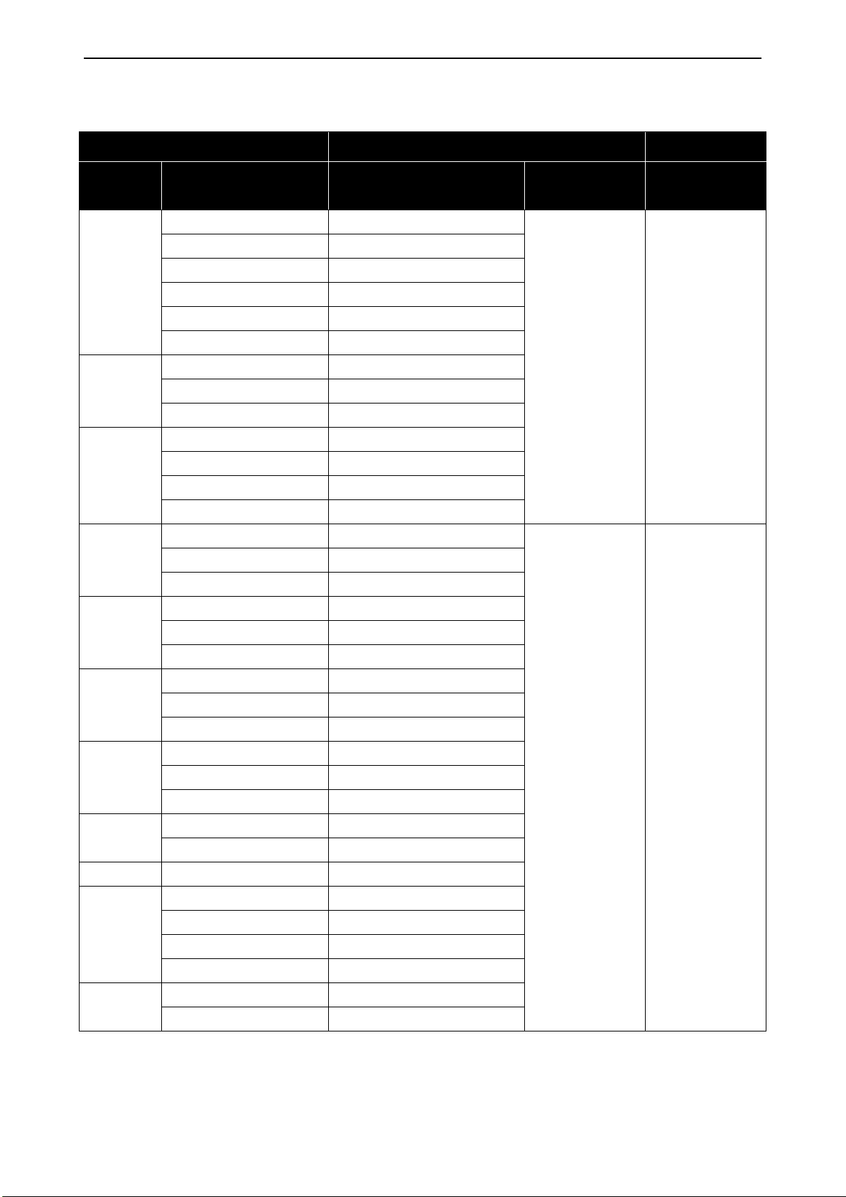
3.3 DC Fuse selection
The fuses on the DC-Input of the inverter must have the following characteristics:
Table 1. Fuse characteristics
Fuse type Min. Voltage rating
DC current 1000 V
It is recommended to use gPV fuses, which are developed for solar application, in order to protect
cables and panels against reverse overcurrent, when multiple strings are connected in parallel.
See chapter 3.4. for recommended gPV fuse manufacturer.
The photovoltaic fuses have to meet the IEC 60269-6 or the UL 2579 standard.
Local contacts: https://www.danfoss.com/en/contact-us/contacts-list/
Page 9
Electrical installation vacon • 9
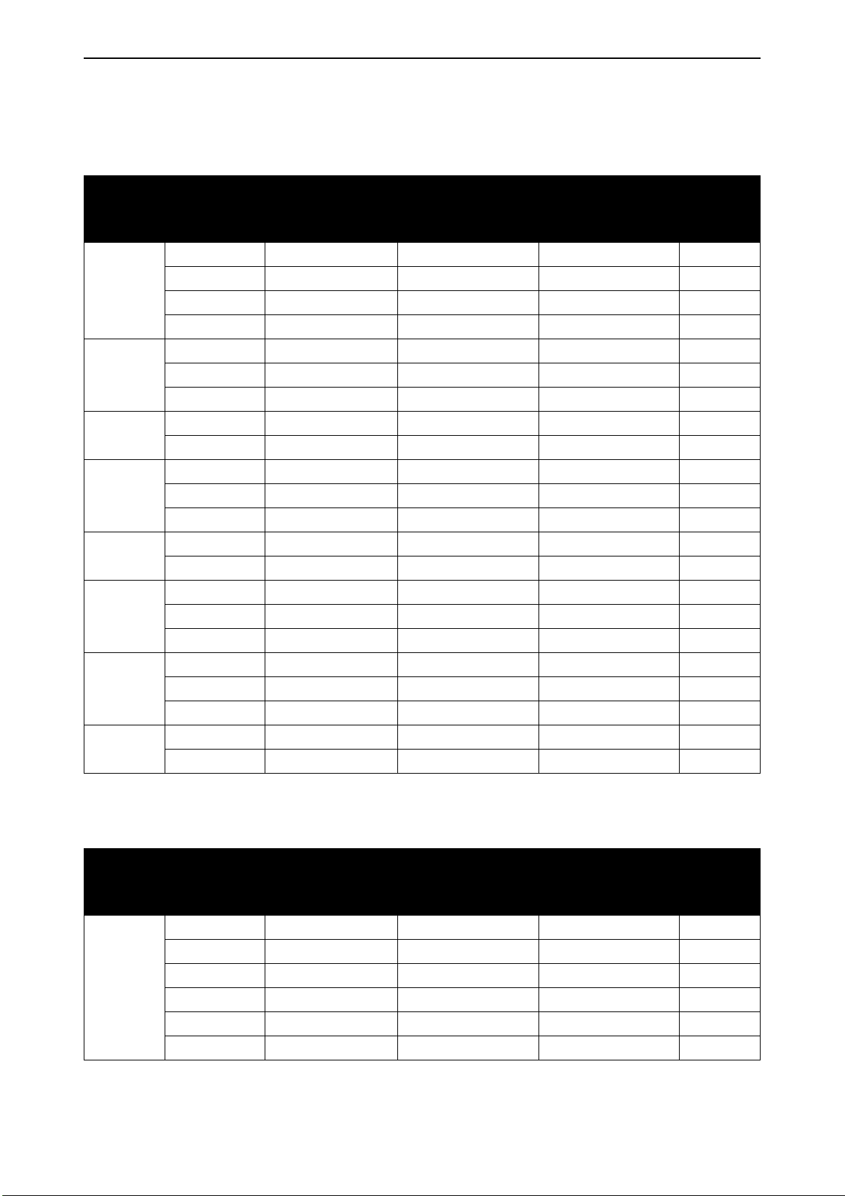
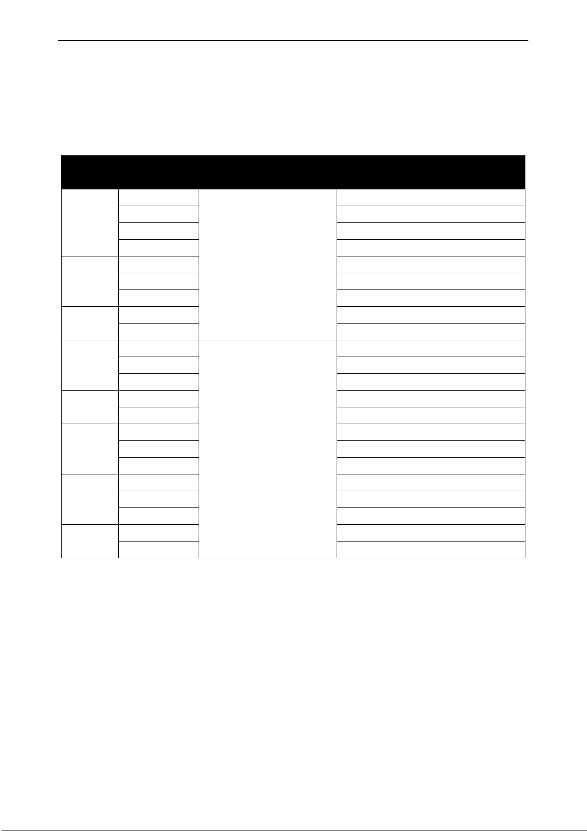
See table below for recommended fuse sizes:
Table 2. Recommended fuse sizes, Mains voltage 3AC 208-240 V, 50/60 Hz, up to 400 V in
VDC
Enclosure
size
MM4
MM5
MM6
MR5
MR6
AC drive type
Rated continuous
current [A]
IEC60269-6 Fuse
size [A]
UL-2579 Fuse size
[A]
0007 6.6 12 12 2
0008 8.0 15 15 2
0011 11.0 20 20 2
0012 12.5 20 25 2
0018 18.0 30 40 2
0024 24.0 40 50 2
0031 31.0 50 63 2
0048 48.0 80 100 2
0062 62.0 100 125 2
0018 18.0 30 40 2
0024 24.0 40 50 2
0031 31.0 50 63 2
0048 48.0 80 100 2
0062 62.0 100 125 2
0075 75.0 125 160 2
Total
number of
fuses
MR7
0088 88.0 160 200 2
0105 105.0 200 200 2
0140 140.0 250 315 2
MR8
0170 170.0 315 400 2
0205 205.0 400 400 2
0261 261.0 500 500 2
MR9A
0310 310.0 600 630 2
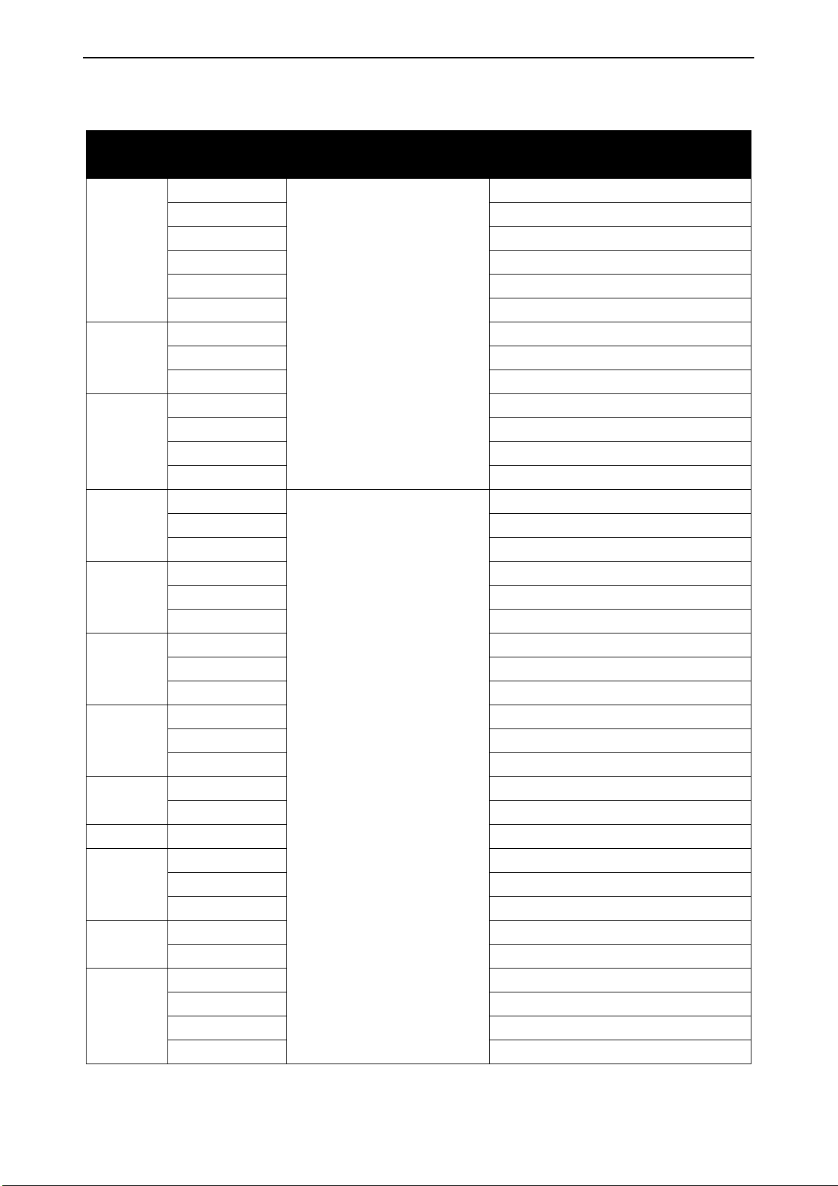
Table 3. Recommended fuse sizes, Mains voltage 3AC 380-480/500 V, 50/60 Hz, up to 800 V
in VDC
Enclosure
size
AC drive type
Rated continuous
current [A]
IEC60269-6 Fuse
size [A]
UL-2579 Fuse size
[A]
Total
number of
fuses
0003 3.4 6 6 2
0004 4.8 8 8 2
0005 5.6 10 10 2
MM4
0008 8.0 12 15 2
0009 9.6 15 16 2
0012 12.0 20 20 2
Local contacts: https://www.danfoss.com/en/contact-us/contacts-list/
Page 10

vacon • 10 Electrical installation
Table 3. Recommended fuse sizes, Mains voltage 3AC 380-480/500 V, 50/60 Hz, up to 800 V
in VDC
Enclosure
size
MM5
MM6
MR5
MR6
MR7
AC drive type
Rated continuous
current [A]
IEC60269-6 Fuse
size [A]
UL-2579 Fuse size
[A]
0016 16.0 25 30 2
0023 23.0 40 40 2
0031 31.0 50 63 2
0038 38.0 63 63 2
0046 46.0 80 80 2
0061 61.0 100 100 2
0072 72.0 125 125 2
0016 16.0 30 30 2
0023 23.0 40 50 2
0031 31.0 50 63 2
0038 38.0 63 80 2
0046 46.0 80 100 2
0061 61.0 100 125 2
0072 72.0 125 150 2
0087 87.0 160 200 2
Total
number of
fuses
0105 105.0 200 200 2
0140 140.0 250 315 2
MR8
0170 170.0 315 400 2
0205 205.0 400 400 2
0261 261.0 500 500 2
MR9A
0310 310.0 600 630 2
MR9B 0386 385.0 2 x 350 2 x 400 4
0385 385.0 2 x 350 2 x 400 4
0460 460.0 2 x 500 2 x 500 4
MR10
0520 520.0 2 x 500 2 x 500 4
0590 590.0 2 x 600 2 x 600 4
0651 650.0 4 x 350 4 x 400 8
MR11
0731 730.0 4 x 400 4 x 400 8
0650 650.0 4 x 350 4 x 400 8
0730 730.0 4 x 400 4 x 400 8
0820 820.0 4 x 400 4 x 500 8
MR12
0920 920.0 4 x 500 4 x 500 8
1040 1040.0 4 x 600 4 x 600 8
1180 1180.0 4 x 600 4 x 630 8
Local contacts: https://www.danfoss.com/en/contact-us/contacts-list/
Page 11

Electrical installation vacon • 11
3.4 Manufacturers of gPV fuses
Recommended manufacturers of gPV type fuses:
• Littelfuse
• Siba
• Bussmann
• Mersen
• ETI
• DF Electric
Local contacts: https://www.danfoss.com/en/contact-us/contacts-list/
Page 12
vacon • 12 Electrical installation
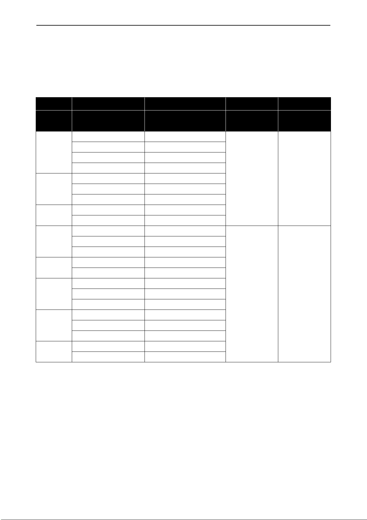
3.5 Parallel diode selection
When VACON® 100 X (MM4-MM6) or VACON® 100 INDUSTRIAL (MR5-MR12) is used in the Solar
Pump application, a diode must be connected between DC+ and DC- to protect the inverter against
reverse voltage. See tables below for diode specification.
Table 4. Diode specification, Mains voltage 3AC 208-240 V, 50/60 Hz, up to 400 V in VDC
AC drive Diode specifications
Enclosure
size
MM4
MM5
MM6
MR5
MR6
MR7
AC drive type min. IFav [A]
0007 15
0008 18
0011 25
0012 28
0018 40
0024 54
0031 70
0048 110
0062 140
0018 50
0024 63
0031 80
0048 125
0062 160
0075 200
0088 250
0105 250
Min. Voltage
rating [V]
1200 1.5
1200 1.5
Max. Vf [V] @
IFav [A]
MR8
MR9A
0140 400
0170 500
0205 500
0261 625
0310 800
Local contacts: https://www.danfoss.com/en/contact-us/contacts-list/
Page 13
Electrical installation vacon • 13
Table 5. Diode specification, Mains voltage 3AC 380-480/500 V, 50/60 Hz, up to 800 V in VDC
AC drive Diode specifications
Enclosure
size
MM4
MM5
MM6
MR5
AC drive type min. IFav [A]
0003 8
0004 12
0005 12
0008 18
0009 22
0012 28
0016 36
0023 50
0031 70
0038 85
0046 100
0061 140
0072 160
0016 40
0023 63
0031 80
Min. Voltage
rating [V]
1200 1.5
Max. Vf [V] @
IFav [A]
0038 100
MR6
0046 125
0061 160
0072 200
MR7
0087 250
0105 250
0140 400
MR8
0170 500
0205 500
0261 625
MR9A
0310 800
MR9B 0386 1000
0385 1000
0460 1250
MR10
0520 1250
0590 1500
0651 2 x 1000
MR11
0731 2 x 1000
1200 1.5
Local contacts: https://www.danfoss.com/en/contact-us/contacts-list/
Page 14

vacon • 14 Electrical installation
Table 5. Diode specification, Mains voltage 3AC 380-480/500 V, 50/60 Hz, up to 800 V in VDC
AC drive Diode specifications
Enclosure
size
MR12
AC drive type min. IFav [A]
0650 2 x 1000
0730 2 x 1000
0820 2 x 1250
0920 2 x 1250
1040 2 x 1500
1180 2 x 1575
Min. Voltage
rating [V]
1200 1.5
Max. Vf [V] @
IFav [A]
Local contacts: https://www.danfoss.com/en/contact-us/contacts-list/
Page 15
Electrical installation vacon • 15
3.6 Photovoltaic system dimensioning
The photovoltaic system has to be dimensioned in order to not exceed the values specified in the
tables below. The VACON® 100 X enclosure sizes are MM4-MM6, and VACON® 100 INDUSTRIAL enclosure sizes are MR5-MR12.
Table 6. AC drive (208…240 V 3AC 50/60Hz, up to 400 V in VDC) DC-link input ratings
Enclosure
size
MM4
MM5
MM6
MR5
MR6
MR7
AC drive type DC supply [VDC]
Max. Recommended PV Array Power
0007
0008 3.0
0011 4.4
0012 6.0
0018 8.0
No tolerance permissible,
0024 11.0
234-400
0%
0031 15.0
0048 22.0
0062 30.0
0018
0024 11.0
0031 15.0
0048 22.0
0062 30.0
0072 37.0
0088 44.0
No tolerance permissible,
0105 60.0
234-400
0%
[kW]
2.2
8.0
MR8
MR9A
0140 74.0
0170 90.0
0205 110.0
0261 150.0
0310 180.0
Local contacts: https://www.danfoss.com/en/contact-us/contacts-list/
Page 16
vacon • 16 Electrical installation
Table 7. AC drive (380…480/500 V 3AC 50/60Hz, up to 800 V in VDC) DC-link input ratings
Enclosure
size
MM4
MM5
MM6
MR5
AC drive type DC supply [VDC]
Max. Recommended PV Array Power
0003
0004 3.0
0005 4.4
0008 6.0
0009 8.0
0012 11.0
0016 15.0
No tolerance permissible,
0023 22.0
300/436*-800
0%
0031 30.0
0038 37.0
0046 44.0
0061 60.0
0072 74.0
0016
0023 22.0
0031 30.0
[kW]
2.2
15.0
0038 37.0
MR6
0046 44.0
0061 60.0
0072 74.0
MR7
0087 90.0
0105 110.0
0140 150.0
MR8
0170 180.0
0205 220.0
436-800
No tolerance permissible,
MR9A
0261 264.0
0%
0310 320.0
MR9B 0385 400.0
0460 500.0
MR10
0520 500.0
0590 630.0
0650 710.0
MR11
0730 800.0
0820 900.0
MR12
0920 1000.0
1040 1120.0
1180 1260.0
Local contacts: https://www.danfoss.com/en/contact-us/contacts-list/
Page 17

Electrical installation vacon • 17
* The minimum value is 300 V when the application version is AMIT1181_V205 and the drive is manufactured after
June 2019.
Local contacts: https://www.danfoss.com/en/contact-us/contacts-list/
Page 18
vacon • 18 Electrical installation
3.7 Grounding
3.7.1 Pole Grounding
It is prohibited to connect any pole, DC+ or DC-, of the photovoltaic system directly to PE.
3.7.2 Drive Grounding
All non-current-carrying metal parts (module frames, enclosures) and also the midpoint of the current carrying conductors of the photovoltaic system must be connected to the PE of the drive.
3.8 AC grid connection
3.8.1 More than one source of supply
It is not recommended to supply the drive simultaneously from the photovoltaic cell and from grid.
3.8.2 Toggle between AC and DC
If both the DC input and the AC input are used (for example, when the energy from the photovoltaic
system is not sufficient), it is not allowed to switch directly between AC and DC supply. When switching from one supply to the other, it is mandatory to wait until the drive is discharged.
The minimum AC-DC switchover delay is 30 s for VACON® 100X MM4-MM6 and VACON® 100 MR5MR6.
The minimum AC-DC switchover delay is 60 s for VACON® 100 MR7-MR12.
DANGER! To completely isolate the equipment, use a two-pole disconnect switch for the photovoltaic input (suitable for DC) and for the grid input (AC switch). Only one of these switches is
allowed to be on at a time. The delay time must be respected when changing from one switch
to the other.
Failure to follow these instructions can lead to death or serious injury.
DANGER! If it is necessary to connect the drive simultaneously on AC and DC supply, note that
if the AC supply is lost, the drive must be separated from the AC supply grid.
Failure to follow these instructions can lead to death or serious injury.
3.8.3 Dual supply functionality
Sometimes a back up from the AC mains is needed in case the power from the photovoltaic supply
is not enough, for example, during night time and cloudy weather. The connection can be created in
several different ways. In this chapter, three alternative solutions are described.
Common safety related topic in every solution is to make sure that in case of possible malfunction
of drive there is no DC voltage connected into AC side. DC voltage from photovoltaic system can
make AC supply side parts energized having dangerous voltage, in case AC power is down. DC voltage can go very far distance wise into AC side, as far as galvanically possible. This can be very dangerous especially during AC grid service. System must have a way to prevent this happening.
3.8.3.1 Changeover switch
Using a manually operated changeover switch is the most recommended way to make the switchover between AC and DC supply. In this case, a digital input can be programmed to select normal reference when using AC supply or MPPT when using DC supply. The changeover switch must have a
potential free auxiliary contact. See parameter P3.5.1.53 Mains Supply On. In case of a failure, the
changeover switch also prevents the DC voltage from going into the AC side.
3.8.3.2 AC and DC connected simultaneously without control
In this case, there is no possibility to have any control if AC or DC supply is used for energy source.
Supply always comes automatically from the source where the voltage is higher. Therefore, photovoltaic dimensioning is very critical. In addition to that, a blocking diode on the DC side is needed to
Local contacts: https://www.danfoss.com/en/contact-us/contacts-list/
Page 19

Electrical installation vacon • 19
protect solar panels in case their voltage is low. On the AC side, function of the blocking diode is
made by drive rectifier diodes. However, in case of malfunction of rectifier diodes also electromechanics separation is needed in case AC supply goes down. It is mandatory to separate the drive
from AC supply in case of power down. There are different methods to make the separation. See
one example in chapter 3.8.3.3.
3.8.3.3 Automatic Dual supply control
This functionality can be used by activating the drive relay output to control additional contactor on
the AC supply side. See the related programming in chapter 7.2.23.3. The functionality can have
three different operation modes:
0 - Always active (supply from AC and DC used together)
Works in the same way as described in chapter 3.8.3.2, but AC supply is only used when the drive is
at Run state.
1 - Closed loop Irradiation
Controls the AC supply contactor based on irradiation measurement on analog input.
2 - Closed loop Sensorless
Controls the AC supply contactor based on periodic PV capacity checks.
In this case, the AC contactor can also be used to separate the drive from mains automatically when
the AC supply goes down. For this, it is mandatory to have a separate control relay on the AC side
to detect supply voltage. This relay can be used to force contactor to switch off. The contactor auxiliary contact should be connected into the drive digital input configured in P3.5.1.60, to tell contactor status.
3.9 External +24V supply
Using external supply can be used to keep control energized when mains power is down. System
software version FW0072V030 or newer should be used.
Local contacts: https://www.danfoss.com/en/contact-us/contacts-list/
Page 20
vacon • 20 Electrical installation
11742_uk
3AC
PE
PE
PES
DC
switch
protection
diode
DC
fuses
DC+
DC
power
supply
DC-
L1 L2 L3
DC-DC+R+R-
U/T1 V/T2 W/T3
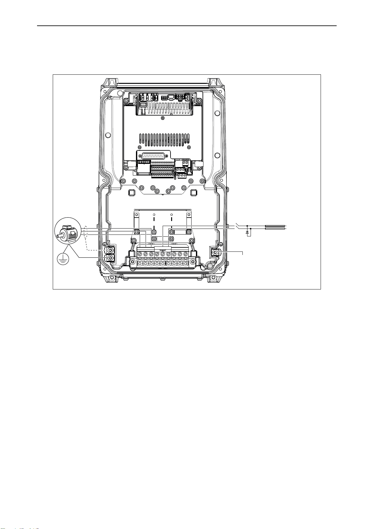
3.10 DC power connection
3.10.1 VACON® 100 X drives
Figure 1. Example of the power connections: MM4/MM5
Local contacts: https://www.danfoss.com/en/contact-us/contacts-list/
Page 21
Electrical installation vacon • 21
L1 L2 L3 U/T1 V/T2 W/T3
DC- DC+R+ R-
11743_uk
DC
switch
protection
diode
DC
fuses
3AC
PE
PE
DC+
DC
power
supply
DC-
PES
3AC
PE
PES
11971_uk
DC
switch
protection
diode
DC
fuses
PE
DC+
DC
power
supply
DC-
U V WL1 L2 L3 DC- DC+ R-
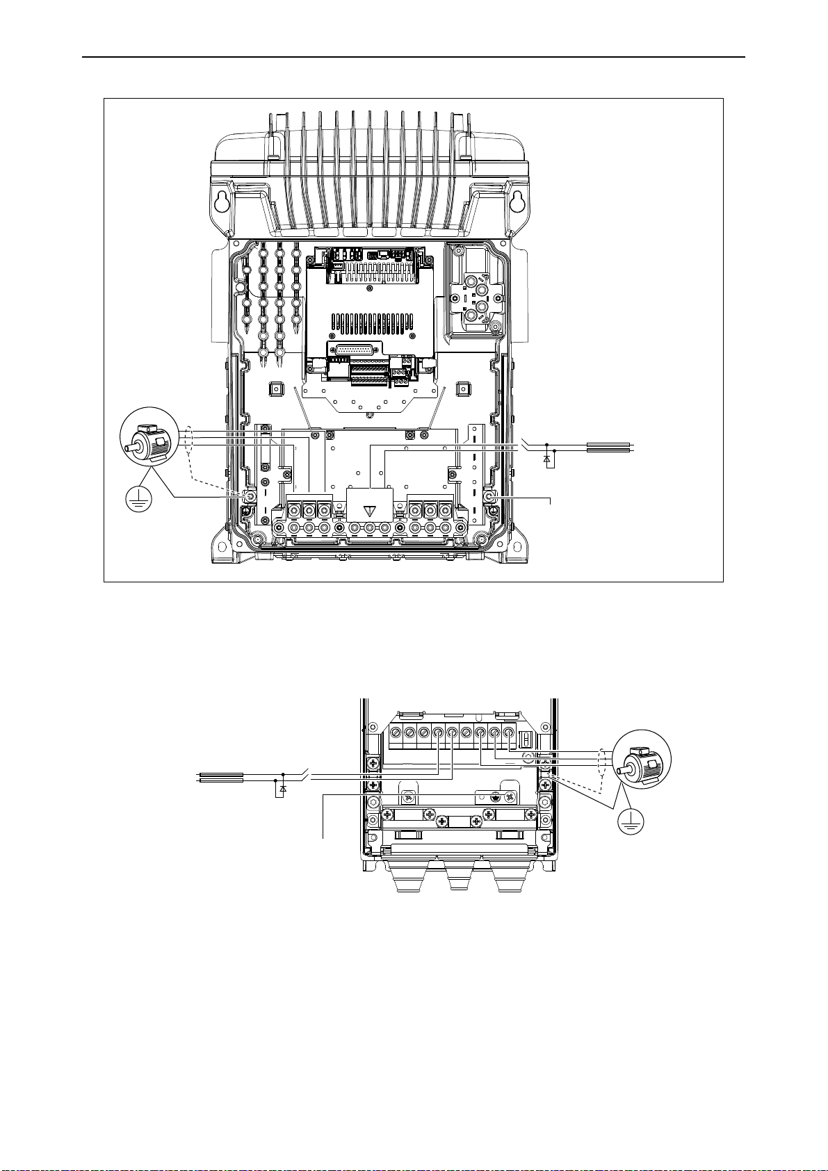
Figure 2. Example of the power connections: MM6
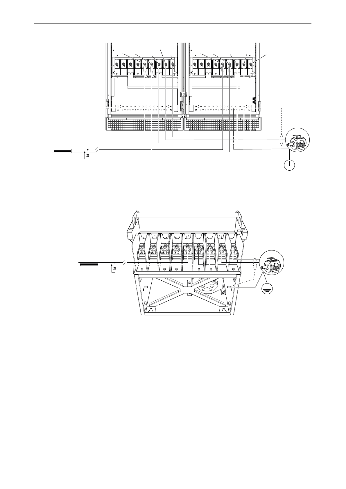
3.10.2 VACON® 100 INDUSTRIAL drives
Figure 3. Example of the power connections: MR5-MR7
Local contacts: https://www.danfoss.com/en/contact-us/contacts-list/
Page 22
vacon • 22 Electrical installation
U V W
DC- DC+
11972_uk
3AC
PE
PES
DC
switch
protection
diode
DC
fuses
PE
DC+
DC
power
supply
DC-
L1 L2 L3
11973_uk
3AC
PE
PES
DC
switch
protection
diode
DC
fuses
PE
DC+
DC
power
supply
DC-
L1 L2 L3 DC-R+R-
U V W
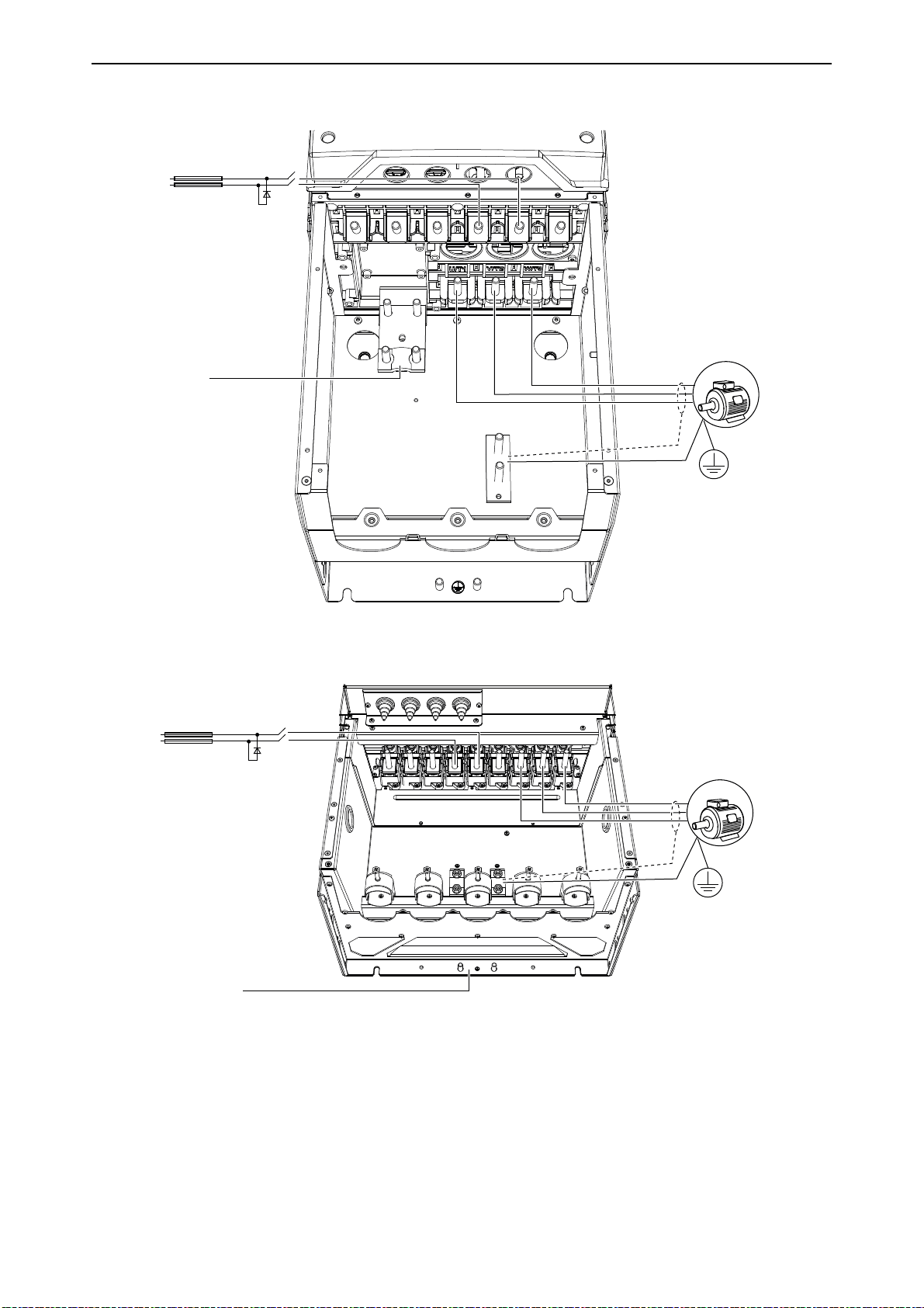
Figure 4. Example of the power connections: MR8
Figure 5. Example of the power connections: MR9
Local contacts: https://www.danfoss.com/en/contact-us/contacts-list/
Page 23
Electrical installation vacon • 23
DC+ U/T1 V/T2 W/T3DC-
3AC
PE
PES
DC
switch
protection
diode
DC
fuses
PE
DC+
DC
power
supply
DC-
7163_uk
DC+
U/T1 V/T2
W/T3
DC-
U/T1 V/T2
W/T3
DC+ DC-
3AC
PE
PES
DC
switch
protection
diode
DC
fuses
PE
DC+
DC
power
supply
DC-
7161_uk
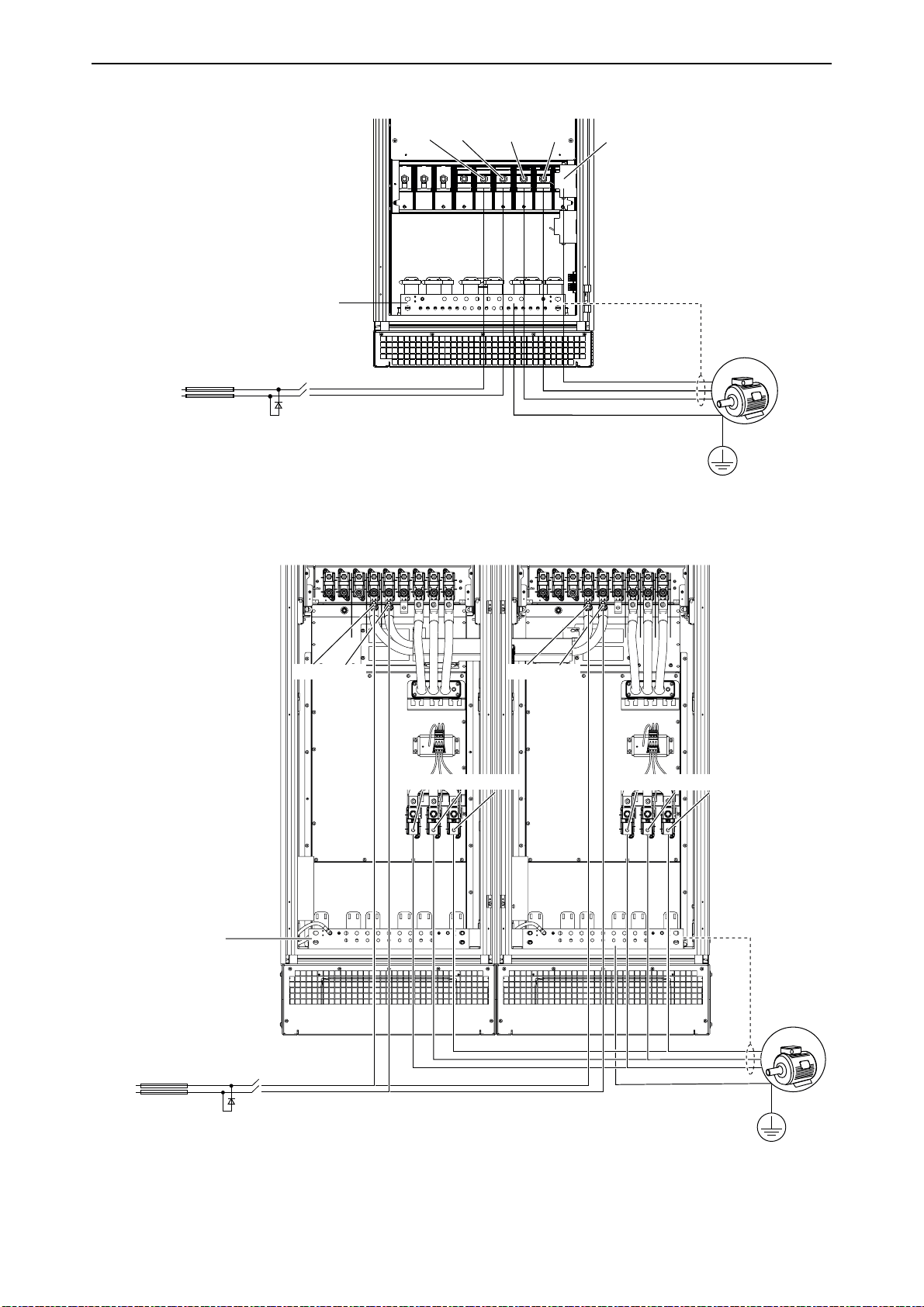
Figure 6. Example of the power connections: MR10 without extension box
Figure 7. Example of the power connections: MR11 without extension box
Local contacts: https://www.danfoss.com/en/contact-us/contacts-list/
Page 24
vacon • 24 Electrical installation
DC+
U/T1 V/T2
W/T3
DC-
DC+ DC-
3AC
PE
PES
DC
switch
protection
diode
DC
fuses
PE
DC+
DC
power
supply
DC-
U/T1
V/T2
W/T3
7162_uk
DC+ DC-
U/T1V/T2W/
T3
3AC
PE
PES
11974_uk
DC
switch
protection
diode
DC
fuses
PE
DC+
DC
power
supply
DC-
Figure 8. Example of the power connections: MR12 without extension box
Figure 9. Example of the power connections: MR10 and MR12 with extension box
Local contacts: https://www.danfoss.com/en/contact-us/contacts-list/
Page 25
Startup vacon • 25
OK
BACK
RESET
4. S
4.1 First Start-up
In the
can start controlling your process. In the Wizard, you will need the following keypad buttons:
Startup Wizard
TARTUP
, you will be prompted for essential information needed by the drive so that it
Left/Right arrows. Use these to easily move between digits and decimals.
Up/Down arrows. Use these to move between options in menu and to change value.
OK button. Confirm selection with this button.
Back/Reset button. Pressing this button, you can return to the previous question in the
Wizard. If pressed at the first question, the Startup Wizard will be canceled.
Once you have connected power to your VACON® 100 X AC drive, follow these instructions to easily
set up your drive.
NOTE: You can have your AC drive equipped with a keypad with either a graphical or a text keypad.
1
2
3
4
5
* These questions appear if battery is installed
Language selection (P6.1) Depends on language package
Russia
Daylight saving* (P5.5.5)
Time* (P5.5.2) hh:mm:ss
Year* (P5.5.4) yyyy
Date* (P5.5.3) dd.mm.
US
EU
OFF
Local contacts: https://www.danfoss.com/en/contact-us/contacts-list/
Page 26
vacon • 26 Startup
6
Push the OK button unless you want to set all parameter values manually.
7
8
9
10
11
12
13
14
15
16
17
Run Startup Wizard?
Make a selection of an application
(P1.2 Application,ID212)
Set a value for P3.1.2.2 Motor
Type (so that it agrees with the
nameplate)
Set value for
Voltg
(according to nameplate)
Set value for
Freq
(according to nameplate)
Set value for
Speed
Set value for
Currnt
Set value for
Phi
Set value
frequency reference
Set
qReference
Set
1
Set
1
(according to nameplate)
(according to nameplate)
value
value
value
P3.1.1.1 Motor Nom
P3.1.1.2 Motor Nom
P3.1.1.3 Motor Nom
P3.1.1.4 Motor Nom
(according to nameplate)
P3.1.1.5 Motor Cos
for
P3.3.1.1 Minimum
for
P3.3.1.2 MaxFre-
for
P3.4.1.2 Accel Time
for
P3.4.1.3 Decel Time
Yes
No
Standard
Local/Remote
Multi-step speed
PID control
Multi-purpose
Motor potentiometer
PM motor
Induction motor
Range:
8.00...320.00 Hz
Range:
Range:
Range:
Range:
Range:
Range:
Range:
Varies
24...19.200 rpm
Varies
0.30...1.00
0.00...50.00 Hz
0.00...320.00 Hz
0.1...300.0 s
0.1...300.0 s
If you set Motor Type to Induction Motor, you see the next question. If your selection is PM Motor,
the value of parameter P3.1.1.5 Motor Cos Phi is set to 1.00 and the wizard goes directly to question
18.
18
19
20
21
Set value
qReference
Set
value
qReference
Set
value
1
Set
value
1
for
P3.3.1.1 MinFre-
for
P3.3.1.2 MaxFre-
for
P3.4.1.2 Accel Time
for
P3.4.1.3 Decel Time
Range:
Range:
Range:
Range:
Local contacts: https://www.danfoss.com/en/contact-us/contacts-list/
0.00...50.00 Hz
0.00...320.00 Hz
0.1...300.0 s
0.1...300.0 s
Page 27

Startup vacon • 27
22
To continue to the application wizard, set the selection to Yes and push the OK button.
After these selections, the Start-up wizard is completed. To start the Start-up wizard again, you
have 2 alternatives. Go to the parameter P6.5.1 Restore Factory Defaults or to the parameter B1.1.2
Start-up Wizard. Then set the value to Activate.
Run the Application wizard?
Yes
No
Local contacts: https://www.danfoss.com/en/contact-us/contacts-list/
Page 28

vacon • 28 Startup
4.2 Description of the applications
Use the parameter P1.2 (Application) to make a selection of an application for the drive. Immediately when the parameter P1.2 changes, a group of parameters get their preset values.
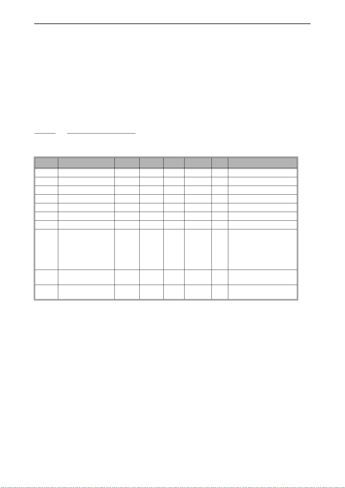
4.2.0.1 M1 Quick setup parameter group
In the Quick Setup parameter group you will find the different wizards of the VACON® 100 X Solar
Pump Application. The wizards help you to quickly set up your drive for use prompting you for a
number of essential data.
Table 8. Quick setup parameter group
Code Parameter Min Max Unit Default ID Description
0 = Do not activate
1 = Activate
B1.1 Startup wizard 0 1 0 1170
P1.2 Application 0 5 0 212
P1.3 MinFreqReference 0.00 P1.4 Hz 0.00 101
P1.4 MaxFreqReference P1.3 320.00 Hz 50.00 102
P1.5 Accel Time 1 0.1 300.0 s 5.0 103
P1.6 Decel Time 1 0.1 300.0 s 5.0 104
P1.7 Current limit Varies Varies A Varies 107
P1.8 Motor type 0 1 0 650
P1.9 Motor Nom Voltg Varies Varies V Varies 110
P1.10 Motor Nom Freq 8.00 320.00 Hz Varies 111
P1.11 Motor Nom Speed 24 19200 rpm Varies 112
P1.12 Motor Nom Currnt Varies Varies A Varies 113
P1.13 Motor Cos Phi 0.30 1.00 0.74 120
Choosing Activate initiates
the Startup Wizard (see
chapter 4.1).
0 = Standard
1 = Local/Remote
2 = Multi-Step Speed
3 = PID Control
4 = Multi-Purpose
5 = Motor
Potentiometer
Minimum allowed frequency reference
Maximum allowed frequency
reference
Defines the time required
for the output frequency to
increase from zero frequency to maximum frequency
Defines the time required
for the output frequency to
decrease from maximum
frequency to zero frequency
Maximum motor current
from AC drive
0 = Induction motor
1 = PM motor
Find this value Un on the
rating plate of the motor.
Note also used connection
(Delta/Star).
Find this value fn on the rating plate of the motor.
Find this value nn on the rating plate of the motor.
Find this value In on the rating plate of the motor.
Find this value on the rating
plate of the motor
Local contacts: https://www.danfoss.com/en/contact-us/contacts-list/
Page 29

Startup vacon • 29
Table 8. Quick setup parameter group
The drive searches for the
minimum motor current in
order to save energy and to
P1.14 Energy optimization 0 1 0 666
P1.15 Identification 0 1 0 631
P1.16 Start function 0 1 0 505
P1.17 Stop function 0 1 0 506
P1.18 Automatic reset 0 1 0 731
P1.19 External fault 0 3 2 701
P1.20 AI Low Fault 0 5 0 700
P1.21 Rem.Ctrl. Place 0 1 0 172
P1.22 I/O A Ref sel 1 9 5 117
lower the motor noise. This
function can be used e.g. in
fan and pump applications
0 = Disabled
1 = Enabled
The identification run calculates or measures the motor
parameters that are necessary for a good control of the
motor and speed.
0 = No action
1 = At standstill
2 = With rotation
Before you do the identification run, you must set the
motor nameplate parameters.
0=Ramping
1=Flying start
0=Coasting
1=Ramping
0 = Disabled
1 = Enabled
0 = No action
1 = Alarm
2 = Fault (Stop according to
stop mode)
3 = Fault (Stop by coasting)
Response when an analogue
signal in use goes below
50% of the minimum signal
range. 0 = No action
1 = Alarm
2 = Alarm, Preset Freq
3 = Alarm, Previous Freq
4= Fault (Stop according to
stop mode)
5 = Fault (Stop by coasting)
Selection of remote control
place (start/stop). Can be
used to change back to
remote control from
VACON® Live e.g. in case of
a broken panel.
0=I/O control
1=Fieldbus control
Selection of ref source when
control place is I/O A
1 = Preset Frequency 0
2 = Keypad reference
3 = Fieldbus
4 = AI1
5 = AI2
6 = AI1+AI2
7 = PID reference
8 = Motor potentiometer
9 = Max Power
Local contacts: https://www.danfoss.com/en/contact-us/contacts-list/
Page 30

vacon • 30 Startup
Table 8. Quick setup parameter group
Selection of ref source when
P1.23 Keypad Ref sel 1 9 2 121
P1.24 Fieldbus Ref sel 1 9 3 122
P1.25 AI1 signal range 0 1 0 379
P1.26 AI2 signal range 0 1 1 390
control place is keypad:
See P1.22
Selection of ref source when
control place is Fieldbus:
See P1.22
0 = 0…10 V / 0…20 mA
1 = 2…10 V / 4…20 mA
0 = 0…10 V / 0…20 mA
1 = 2…10 V / 4…20 mA
Local contacts: https://www.danfoss.com/en/contact-us/contacts-list/
Page 31

Startup vacon • 31
Table 8. Quick setup parameter group
Function selection for Basic
R01:
0 = None
1 = Ready
2 = Run
3 = General fault
4 = General fault inverted
5 = General alarm
6 = Reversed
7 = At speed
8 = Thermistor fault
9 = Motor regulator active
10 = Start signal active
11 = Keypad control active
12 = I/O B control activated
13 = Limit supervision 1
14 = Limit supervision 2
15 = SinglePowerOn
16 = No function
17 = Preset speed active
18 = No function
19 = PID in Sleep mode
20 = PID soft fill active
21 = PID supervision limits
22 = Ext. PID superv. limits
23 = Input press. alarm/fault
24 = Frost prot. alarm/fault
25 - 30 = No function
31 = RTC time chnl 1 control
32 = RTC time chnl 2 control
P1.27 RO1 function 0 60 2 11001
P1.28 Basic R02 function 0 46 3 11004 See P1.27
33 = RTC time chnl 3 control
34 = FB ControlWord B13
35 = FB ControlWord B14
36 = FB ControlWord B15
37 = FB ProcessData1.B0
38 = FB ProcessData1.B1
39 = FB ProcessData1.B2
40 = Maintenance alarm
41 = Maintenance fault
42 = No function
43 = No function
44 = Block Out.1
45 = Block Out.2
46 = Block Out.3
47 = Block Out.4
48 = Block Out.5
49 = Block Out.6
50 = Block Out.7
51 = Block Out.8
52 = Block Out.9
53 = Block Out.10
54 = No function
55 = No function
56 = Auto-cleaning
active
57 = Motor Switch
Open
58 = TEST (Always
Closed)
59 = No function
60 = DualSupply AC switch
Local contacts: https://www.danfoss.com/en/contact-us/contacts-list/
Page 32

vacon • 32 Startup
Table 8. Quick setup parameter group
0=TEST 0% (Not used)
1=TEST 100%
2=Output freq (0 -fmax)
3=Freq reference (0-fmax)
4=Motor speed (0 - Motor
nominal speed)
P1.30 AO1 function 0 19 2 10050
5=Output current (0-I
)
tor
6=Motor torque (0-T
7=Motor power (0-P
8=Motor voltage (0-U
)
tor
9=DC link voltage (0-1000 V)
10=PID1 output (0-100%)
11=Ext.PID output (0-100%)
12=ProcessDataIn1 (0100%)
13=ProcessDataIn2 (0100%)
14=ProcessDataIn3 (0100%)
15=ProcessDataIn4 (0100%)
16=ProcessDataIn5 (0100%)
17=ProcessDataIn6 (0100%)
18=ProcessDataIn7 (0100%)
19=ProcessDataIn8 (0100%)
nMo-
nMotor
nMotor
nMo-
)
)
Local contacts: https://www.danfoss.com/en/contact-us/contacts-list/
Page 33

Startup vacon • 33
4.2.1 Standard application
You can use the Standard application in speed-controlled processes where no special functions are
necessary, for example pumps, fans, or conveyors.
It is possible to control the drive from the keypad, Fieldbus or I/O terminal.
When you control the drive with the I/O terminal, the frequency reference signal is connected to AI1
(0…10 V) or AI2 (4…20 mA). The connection depends the type of the signal. There are also 3 preset
frequency references available. You can activate the preset frequency references with DI4 and DI5.
The start/stop signals of the drive are connected to DI1 (start forward) and DI2 (start reverse).
It is possible to configure all the drive outputs freely in all the applications. There are 1 analogue
output (Output Frequency) and 3 relay outputs (Run, Fault, Ready) available on the basic I/O board.
4.2.1.1 M1.31 Standard
Table 9. Standard start-up wizard menu
Code Parameter Min Max Unit Default ID Description
Make the selection of a
P1.31.1 Preset Freq 1 P1.3 P1.4 Hz 10.0 105
P1.31.2 Preset Freq 2 P1.3 P1.4 Hz 15.0 106
P1.31.3 Preset Freq 3 P1.3 P1.4 Hz 20.0 126
preset frequency with
the digital input DI4.
Make the selection of a
preset frequency with
the digital input DI5.
Make the selection of a
preset frequency with
the digital input DI4
and DI5.
Local contacts: https://www.danfoss.com/en/contact-us/contacts-list/
Page 34
vacon • 34 Startup
4.2.2 Local/Remote application
Use the Local/Remote application when, for example, it is necessary to switch between 2 different
control places.
To change between the Local and the Remote control place, use DI6. When Remote control is active,
you can give the start/stop commands from Fieldbus or from I/O terminal (DI1 and DI2). When Local
control is active, you can give the start/stop commands from the keypad, Fieldbus or I/O terminal
(DI4 and DI5).
For each control place, you can make a selection of the frequency reference from the keypad, Fieldbus or I/O terminal (AI1 or AI2).
It is possible to configure all the drive outputs freely in all the applications. There are 1 analogue
output (Output Frequency) and 3 relay outputs (Run, Fault, Ready) available on the basic I/O board.
4.2.2.1 M1.33 Local/Remote
Table 10. Local/Remote start-up wizard menu
Code Parameter Min Max Unit Default ID Description
Selection of ref source when
control place is I/O B. See
P1.32.1 I/O B Ref sel 1 9 9 131
P1.32.2 I/O B Ctrl force
P1.32.3 I/O B Ref force
P1.32.4 Ctrl signal 1 B
P1.32.5 Ctrl signal 2 B
P1.32.6 Keypad Ctrl force
P1.32.7 Fieldbus Ctrl force
P1.32.8 Ext fault close
P1.32.9 Ext fault open
DigIN
SlotA.6
DigIN
SlotA.6
DigIN
SlotA.4
DigIN
SlotA.5
DigIN
Slot0.1
DigIN
Slot0.1
DigIN
SlotA.3
DigIN
Slot0.2
above.
NOTE: I/O B control place
can only be forced active
with digital input (P3.5.1.7).
TRUE = Used frequency reference is specified by I/O
343
reference B parameter
(P3.3.1.6).
411 Force control to fieldbus
Start signal 1 when control
423
place is I/O B
Start signal 2 when control
424
place is I/O B
410 Force control to keypad
411 Force control to fieldbus
FALSE = OK
405
TRUE = External fault
FALSE = External fault
406
TRUE = OK
Local contacts: https://www.danfoss.com/en/contact-us/contacts-list/
Page 35
Startup vacon • 35
4.2.3 Multi-step application
You can use the Multi-step speed application with processes where more than 1 fixed frequency reference is necessary (for example test benches).
It is possible to use 1 + 7 frequency references: 1 basic reference (AI1 or AI2) and 7 preset references.
Make a selection of the preset frequency references with digital signals DI4, DI5 and DI6. If none of
these inputs are active, the frequency reference is removed from the analogue input (AI1 or AI2).
Give the start/stop commands from the I/O terminal (DI1 and DI2).
It is possible to configure all the drive outputs freely in all the applications. There are 1 analogue
output (Output Frequency) and 3 relay outputs (Run, Fault, Ready) available on the basic I/O board.
4.2.3.1 M1.33 Multi-step speed
Table 11. Multi-step speed start-up wizard menu
Code Parameter Min Max Unit Default ID Description
P1.33.1 Preset Freq 1 P1.3 P1.4 Hz 10.0 105
P1.33.2 Preset Freq 2 P1.3 P1.4 Hz 15.0 106
P1.33.3 Preset Freq 3 P1.3 P1.4 Hz 20.0 126
P1.33.4 Preset Freq 4 P1.3 P1.4 Hz 25.0 127
P1.33.5 Preset Freq 5 P1.3 P1.4 Hz 30.0 128
P1.33.6 Preset Freq 6 P1.3 P1.4 Hz 40.0 129
P1.33.7 Preset Freq 7 P1.3 P1.4 Hz 50.0 130
0 = Binary coded
1 = Number of inputs. Preset
P1.33.8 PresetFreqMode 0 1 0 182
P1.33.9 Ext fault close
P1.33.10 Ext fault open
DigIN
SlotA.3
DigIN
Slot0.2
frequency is selected
according to how many of
preset speed digital inputs
are active
FALSE = OK
405
TRUE = External fault
FALSE = External fault
406
TRUE = OK
Local contacts: https://www.danfoss.com/en/contact-us/contacts-list/
Page 36

vacon • 36 Startup
4.2.4 PID Control application
You can use the PID control application with processes where you control the process variable (for
example pressure) through control of the speed of the motor.
In this application, the internal PID controller of the drive is configured for 1 setpoint and 1 feedback
signal.
It is possible to use 2 control places. Make the selection of the control place A or B with DI6. When
control place A is active, the start/stop commands are given by DI1, and the PID controller gives the
frequency reference. When control place B is active, start/stop commands are given by DI4, and AI1
gives the frequency reference.
It is possible to configure all the drive outputs freely in all the applications. There are 1 analogue
output (Output Frequency) and 3 relay outputs (Run, Fault, Ready) available on the basic I/O board.
4.2.4.1 M1.34 PID Control
Table 12. PID Control start-up wizard menu
Code Parameter Min Max Unit Default ID Description
If the value of the parameter
is set to 100% a change of
P1.34.1 Gain 0.00 1000.00 % 100.00 118
P1.34.2 Integration Time 0.00 600.00 s 1.00 119
P1.34.3 Derivation Time 0.00 100.00 s 0.00 132
10% in the error value
causes the controller output
to change by 10%.
If this parameter is set to
1,00s a change of 10% in the
error value causes the controller output to change by
10.00%/s.
If this parameter is set to
1,00s a change of 10% in the
error value during 1.00 s
causes the controller output
to change by 10.00%.
Local contacts: https://www.danfoss.com/en/contact-us/contacts-list/
Page 37

Startup vacon • 37
Table 12. PID Control start-up wizard menu
0 = Not used
1 = AI1
2 = AI2
3 = AI3
4 = AI4
5 = AI5
6 = AI6
7 = ProcessDataIn1
8 = ProcessDataIn2
9 = ProcessDataIn3
10 = ProcessDataIn4
11 = ProcessDataIn5
12 = ProcessDataIn6
P1.34.4 FB 1 Source 0 20 2 334
P1.34.5 SP 1 Source 0 22 1 332
P1.34.6 Keypad SP 1 Varies Varies Varies 0 167
13 = ProcessDataIn7
14 = ProcessDataIn8
15 = Temperature input 1
16 = Temperature input 2
17 = Temperature input 3
18 = Temperature input 4
19 = Temperature input 5
20 = Temperature input 6
AI’s and ProcessDataIn are
handled as % (0.00-
100.00%) and scaled according to Feedback min and
max.
NOTE: ProcessDataIn use
two decimals.
0 = Not used
1 = Keypad setpoint 1
2 = Keypad setpoint 2
3 = AI1
4 = AI2
5 = AI3
6 = AI4
7 = AI5
8 = AI6
9 = ProcessDataIn1
10 = ProcessDataIn2
11 = ProcessDataIn3
12 = ProcessDataIn4
13 = ProcessDataIn5
14 = ProcessDataIn6
15 = ProcessDataIn7
16 = ProcessDataIn8
17 = Temperature input 1
18 = Temperature input 2
19 = Temperature input 3
20 = Temperature input 4
21 = Temperature input 5
22 = Temperature input 6
AI’s and ProcessDataIn are
handled as percent (0.00-
100.00%) and scaled according to Setpoint minimum
and maximum. NOTE: ProcessDataIn signals use 2
decimals.
Local contacts: https://www.danfoss.com/en/contact-us/contacts-list/
Page 38

vacon • 38 Startup
Table 12. PID Control start-up wizard menu
Drive goes to sleep mode
when the output frequency
P1.34.7 SP 1 Sleep Freq 0.00 320.00 Hz 0.00 1016
P1.34.8 SP 1 Sleep Delay 0 3000 s 0 1017
P1.34.9 SP 1 WakeUpLevel Varies 0.00 1018
P1.34.10 Preset Freq 1 P1.3 P1.4 Hz 10.0 105 Preset Freq 1
stays below this limit for a
time greater than that
defined by parameter Sleep
delay.
The minimum amount of
time the frequency has to
remain below the Sleep level
before the drive is stopped.
Defines the level for the PID
feedback value wake-up
supervision. Uses selected
process units.
Local contacts: https://www.danfoss.com/en/contact-us/contacts-list/
Page 39

Startup vacon • 39
4.2.5 Multi-purpose application
You can use the Multi-purpose application for different processes (for example conveyors) where a
wide range of motor control functions is necessary.
It is possible to control the drive from the keypad, Fieldbus or I/O terminal. When you use I/O terminal control, the start/stop commands are given through DI1 and DI2, and the frequency reference
from AI1 or AI2.
There are 2 acceleration/deceleration ramps available. The selection between Ramp1 and Ramp2
is made by DI6.
It is possible to configure all the drive outputs freely in all the applications. There are 1 analogue
output (Output Frequency) and 3 relay outputs (Run, Fault, Ready) available on the basic I/O board.
4.2.5.1 M1.35 Multi-purpose
Table 13. Multi-purpose start-up wizard menu
Code Parameter Min Max Unit Default ID Description
P1.35.1 Control mode 0 1 0 600
P1.35.2 Auto TorqueBoost 0 1 0 109
P1.35.3
P1.35.5 Preset Freq 1 P1.3 P1.4 Hz 10.0 105 Preset Freq 1
P1.35.6 U/f ratio 0 2 0 108
P1.35.7 Field WeakngPnt 8.00 P3.3.1.2 Hz Varies 602
P1.35.8 Voltage at FWP 10.00 200.00 % 100.00 603
P1.35.9 U/f Mid Freq 0.00 P3.1.4.2 Hz Varies 604
P1.35.10 U/f Mid Voltg 0.0 100.0 % 100.0 605
Start Acceleration
Time
0.1 3000.0 s 2.0 502 Start Acceleration Time
0 = U/f Freq ctrl open loop
1 = Speed control open loop
Automatic torque boost can
be used in application where
starting torque due to starting friction is high.
0= Disabled
1= Enabled
Type of U/f curve between
zero frequency and the field
weakening point.
0=Linear
1=Squared
2=Programmable
The field weakening point is
the output frequency at
which the output voltage
reaches the field weakening
point voltage
Voltage at field weakening
point in % of motor nominal
voltage
Provided that the programmable U/f curve has been
selected (par. P3.1.4.1) , this
parameter defines the middle point frequency of the
curve.
Provided that the programmable U/f curve has been
selected (par. P3.1.4.1), this
parameter defines the middle point voltage of the
curve.
Local contacts: https://www.danfoss.com/en/contact-us/contacts-list/
Page 40

vacon • 40 Startup
Table 13. Multi-purpose start-up wizard menu
This parameter defines the
P1.35.11 Zero Freq Voltg 0.00 40.00 % Varies 606
P1.35.12 StartMagnCurrent 0.00 Varies A Varies 517
P1.35.13 StartMagnTime 0,00 600,00 s 0,00 516
P1.35.14 DC Brake Current Varies Varies A Varies 507
P1.35.15 DC BrakeTime 0,00 600,00 s 0,00 508
P1.35.16 DC Start Freq 0,10 10,00 Hz 1,50 515
P1.35.17 Load drooping 0.00 50.00 % 0.00 620
P1.35.18 Load drooping time 0.00 2.00 s 0.00 656
P1.35.19 Load drooping mode 0 1 0 1534
zero frequency voltage of the
U/f curve. The default value
varies according to unit size.
Defines the DC current fed
into motor at start. Disabled
if set to 0.
This parameter defines the
time for how long DC current is fed to motor before
acceleration starts.
Defines the current injected
into the motor during DCbraking.
0 = Disabled
Determines if braking is ON
or OFF and the braking time
of the DC-brake when the
motor is stopping.
The output frequency at
which the DC-braking is
applied.
The drooping function
enables speed drop as a
function of load. Drooping
will be defined in percent of
nominal speed at nominal
load.
Load drooping is used in
order to achieve a dynamic
speed drooping because of
changing load. This parameter defines the time during
which the speed is restored
to the level it was before the
load increase.
0 = Normal; Load drooping
factor is constant through
the whole frequency range
1 = Linear removal; Load
drooping is removed linearly from nominal frequency to zero frequency
Local contacts: https://www.danfoss.com/en/contact-us/contacts-list/
Page 41

Startup vacon • 41
4.2.6 Motor potentiometer application
Use the Motor potentiometer application for the processes where the frequency reference of the
motor is controlled (that is, increased and decreased) through digital inputs.
In this application, the I/O terminal is set to the default control place. the start/stop commands are
given with DI1 and DI2. The frequency reference of the motor is increased with DI5 and decreased
with DI6.
It is possible to configure all the drive outputs freely in all the applications. There are 1 analogue
output (Output Frequency) and 3 relay outputs (Run, Fault, Ready) available on the basic I/O board.
4.2.6.1 M1.36 Motor Potentiom
Table 14. Motor Potentiom start-up wizard menu
Code Parameter Min Max Unit Default ID Description
Rate of change in the motor
potentiometer reference
P1.36.1 MotPot ramp time 0.1 500.0 Hz/s 10.0 331
P1.36.2 MotPot Reset 0 2 1 367
P1.36.3 Preset Freq 1 P1.3 P1.4 Hz 20.0 105
when increased or
decreased with parameters
P3.3.4.1 or P3.3.4.2.
Motor potentiometer frequency reference reset
logic.
0 = No reset
1 = Reset if stopped
2 = Reset if powered down
Make the selection of a
preset frequency with
the digital input DI4
and DI5.
Local contacts: https://www.danfoss.com/en/contact-us/contacts-list/
Page 42

vacon • 42 User interfaces
9086.emf
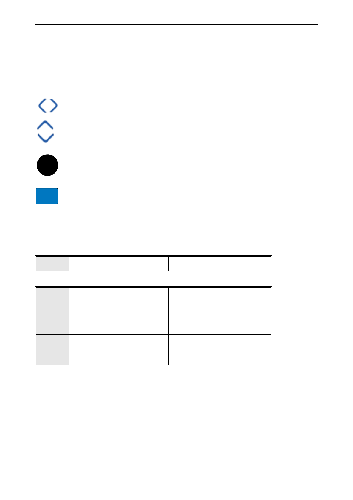
FUNCT
Scroll menu up
Increase value
Scroll menu down
Decrease value
Move cursor left Move cursor right
Move backward in menu
Exit edit mode
Reset faults with long press
Change control place
Access control page
Change direction
Stop button Start button
Enter active level/item
Confirm selection
5. U
SER INTERFACES
5.1 Keypad of the drive
The control keypad is the interface between the VACON® 100 AC drive and the user. With the control
keypad it is possible to control the speed of a motor, to supervise the state of the equipment and to
set the AC drive's parameters.
There are two keypad types you can choose for your user interface:
and
Text keypad
.
5.1.1 Buttons
The button section of the keypad is identical for both keypad types.
Keypad with graphical display
Figure 10. Keypad buttons
5.1.2 Display
The keypad display indicates the status of the motor and the drive and any irregularities in motor or
drive functions. On the display, the user sees information about the drive and
the menu structure and the item displayed.
5.1.3 Navigation on keypad
The data on the control keypad are arranged in menus and submenus. Use the Up and Down arrows
to move between the menus. Enter the group/item by pressing the OK button and
mer level by pressing the Back/Reset button.
The
Location field
indicates your current location. The
Status field
present status of the drive. See Figure 10.
Local contacts: https://www.danfoss.com/en/contact-us/contacts-list/
his present
return
location in
to the for-
gives information about the
Page 43

User interfaces vacon • 43
9159.emf
Main Menu
Quick Setup
( 17 )
Parameters
( 12 )
0
STOP READY I/O
ID: M1
( 5 )
Monitor
0
Status field
STOP/RUN
Direction
ALARM
Status field
READY/NOT READY/FAULT
Control place:
PC/IO/KEYPAD/FIELDBUS
Activated group/item:
Press OK to enter
Number of items
in the group
Location field
(Parameter ID number and
current menu location
0
Start/Stop Setup
Rem Control Place
I/O Control
KeypadStopButton
Yes
Start Function
Ramping
STOP READY I/O
ID:172 M3.2.1
0
Edit
Help
Add to favorites
Rem Control Place
STOP READY I/O
ID: M3.2.1
0
Rem Control Place
STOP READY I/O
M3.2.1
I/O Control
FieldbusCTRL
0
Start/Stop Setup
Rem Control Place
I/O Control
KeypadStopButton
Yes
Start Function
Ramping
STOP READY I/O
ID:172 M3.2.1
0
Rem Control Place
STOP READY I/O
M3.2.1
I/O Control
FieldbusCTRL
OK OK
OK
BACK
RESET
OR:
9160.emf
5.1.4 graphical keypad
Figure 11. Main menu
5.1.4.1 Using the graphical keypad
Editing values
The selectable values can be accessed and edited in two different ways on the graphical keypad.
Parameters with one valid value
Typically, one parameter is set one value. The value is selected either from a list of values (see example below) or the parameter is given a numerical value from a defined range (e.g. 0.00...50.00
Hz).
Change value of a parameter following the procedure below:
1. Locate the parameter.
2. Enter the
Edit
mode.
3. Set new value with the arrow buttons up/down. You can also move from digit to digit with the
arrow buttons left/right if the value is numerical and then change the value with the arrow buttons up/down.
4. Confirm change with OK button or ignore change by returning to previous level with Back/
Reset button.
Local contacts: https://www.danfoss.com/en/contact-us/contacts-list/
Page 44

vacon • 44 User interfaces
9257.emf
OK
9256.emf
...
OK
Symbol for checkbox selection
Figure 12. Typical editing of values on graphical keypad (text value)
Figure 13. Typical editing of values on graphical keypad (numerical value)
Parameters with checkbox selection
Some parameters allow selecting several values. Make a checkbox selection at each value you wish
to activate as instructed below.
Figure 14. Applying the checkbox value selection on graphical keypad
Resetting fault
Instructions for how to reset a fault can be found in chapter 8 .
Function button
The FUNCT button is used for four functions:
1. to quickly access the Control page,
2. to easily change between the Local (Keypad) and Remote control places,
3. to change the rotation direction and
4. to quickly edit a parameter value.
Control places
The
control place
is the source of control where the drive can be started and stopped. Every control
place has its own parameter for selecting the frequency reference source. The
is always the keypad. The
Remote control place
is determined by parameter P3.2.1 (I/O or Field-
bus). The selected control place can be seen on the status bar of the keypad.
Local contacts: https://www.danfoss.com/en/contact-us/contacts-list/
Local control place
Page 45

User interfaces vacon • 45
Main Menu
Parameters
( 15 )
0
Diagnostics
0
STOP READY Keypad
ID: M1
( 7 )
Monitor
0
( 6 )
ID:
Choose action
STOP Ready Keypad
ID:1805
Local/Remote
Control page
Change direction
?
Remote
ID:
Local/Remote
STOP READY Keypad
ID:211
Remote
Local
Main Menu
Parameters
( 15 )
0
Diagnostics
0
STOP READY I/O
ID: M1
( 7 )
Monitor
0
( 6 )
FUNCT
OK
OK
9161.emf
Remote control place
I/O A, I/O B and Fieldbus can be used as remote control places. I/O A and Fieldbus have the lowest
priority and can be chosen with parameter P3.2.1
(Rem Control Place)
. I/O B, again, can bypass the
remote control place selected with parameter P3.2.1 using a digital input. The digital input is selected with parameter P3.5.1.7
(I/O B Ctrl Force)
.
Local control
Keypad is always used as control place while in local control. Local control has higher priority than
remote control. Therefore, if, for example, bypassed by parameter P3.5.1.7 through digital input
while in
Remote
, the control place will still switch to Keypad if
Local
is selected. Switching between
Local and Remote Control can be done by pressing the FUNCT-button on the keypad or by using the
"Local/Remote" (ID211) parameter.
Changing control places
Change of control place from
1. Anywhere in the menu structure, push the
2. Push the
Arrow up
or the
Remote
to
Arrow down
Local
(keypad).
FUNCT
button.
button to select
Local/Remote
and confirm with the OK
button.
3. On the next display, select
4. The display will return to the same location as it was when the
Local
or
Remote
and again confirm with the OK button.
FUNCT
button was pushed. However, if the Remote control place was changed to Local (Keypad) you will be prompted for keypad reference.
Figure 15. Changing control places
Accessing the control page
The
Control page
1. Anywhere in the menu structure, push the
2. Push the
button.
3. The control page appears
If keypad control place and keypad reference are selected to be used you can set the
Reference
used the display will show Frequency reference which is not editable. The other values on the
page are Multimonitoring values. You can choose which values appear here for monitoring (for
this procedure, see page 55).
Local contacts: https://www.danfoss.com/en/contact-us/contacts-list/
is meant for easy operation and monitoring of the most essential values.
FUNCT
Arrow up
after having pressed the OK button. If other control places or reference values are
or the
Arrow down
button to select
button.
Control page
and confirm with the OK
Keypad
Page 46

vacon • 46 User interfaces
Main Menu
Parameters
( 15 )
0
Diagnostics
0
STOP READY I/O
ID: M1
( 7 )
Monitor
0
( 6 )
ID:
Choose action
STOP Ready Keypad
ID:1805
Local/Remote
Control page
Change direction
STOP READY Keypad
( 6 )
Keypad Reference
0.00 Hz
Output Frequ ency
0.00Hz
Motor Curren t
0.00A
Motor Torque
0.00%
0.00%
Motor Power
ID:184
Keypad
0.00 Hz
Output Frequ ency
0.00Hz
Motor Curren t
0.00A
Motor Torque
0.00%
0.00%
Motor Power
STOP READY Keypad
( 6 )
ID:168
Keypad Reference
0.00 Hz
Output Frequ ency
0.00Hz
Motor Curren t
0.00A
Motor Torque
0.00%
0.00%
Motor Power
FUNCT
OK
OK
OK
9162.emf
Main Menu
Parameters
( 15 )
0
Diagnostics
0
STOP READY I/O
ID: M1
( 7 )
Monitor
0
( 6 )
ID:
Choose action
RUN Ready Keypad
ID:1805
Local/Remote
Control page
Change direction
ID:
Choose action
RUN Ready Keypad
ID:1805
Forward
Reverse
Main Menu
Parameters
( 15 )
0
Diagnostics
0
STOP READY I/O
ID: M1
( 7 )
Monitor
0
( 6 )
FUNCT
OK OK
9163.ai
Figure 16. Accessing Control page
Changing direction
Rotation direction of the motor can quickly be changed by applying the FUNCT button.
ing direction
command is not visible in the menu unless the selected control place is
NOTE!
Local
Chang-
.
1. Anywhere in the menu structure, push the Funct button.
2. Push the Arrow up or the Arrow down button to select Change direction and confirm with the OK
button.
3. Then choose the direction you wish to run the motor to. The actual rotation direction is blinking.
Confirm with the OK button.
4. The rotation direction changes immediately and the arrow indication in the status field changes.
Quick edit
Through the
parameter’s ID number.
1. Anywhere in the menu structure, push the FUNCT button.
2. Push the Arrow up or the Arrow down buttons to select Quick Edit and confirm with the OK button.
Quick edit
functionality you can quickly access the desired parameter by entering the
Local contacts: https://www.danfoss.com/en/contact-us/contacts-list/
Page 47

User interfaces vacon • 47
STOP READY Keypad
Main Menu
00
0
0
Favourites
( 0 )
( 4 )
ID: M6
User settings
I/O and Hardware
( 8 )
0
STOP READY Keypad
0
0
Drive name
( 3 )
ID:
User settings
Application selection
HVAC
M6.5M6.5
Parameter backup
Drive
STOP READY Keypad
0
Restore from keypad
ID:
Restore factory defaults
M6.5M6.5.1
Save to keypad
Parameter backup
OK OK
9164.emf
3. Then enter the ID number of parameter or monitoring value you wish to access. Press OK button to confirm.
4. Requested Parameter/Monitoring value appears on the display (in editing/monitoring mode.)
Copying parameters
NOTE:
This feature is available in graphical keypad only.
The parameter copy function can be used to copy parameters from one drive to another.
The parameters are first saved to the keypad, then the keypad is detached and connected to another
drive. Finally the parameters are downloaded to the new drive restoring them from the keypad.
Before any parameters can successfully be copied from the keypad to the drive, the drive has to be
stopped before the parameters are uploaded.
• First go into
eter backup
•
Restore factory defaults
User settings
menu and locate the
Parameter backup
submenu. In the
submenu, there are three possible functions to be selected:
will re-establish the parameter settings originally made at the fac-
tory.
• By selecting
•
Restore from keypad
Figure 17. Parameter copy
NOTE:
If the keypad is changed between drives of different sizes, the copied values of these param-
Save to keypad
will copy all parameters from keypad to a drive.
you can copy all parameters to the keypad.
eters will not be used:
Motor nominal current (
Motor nominal voltage (
Motor nominal speed (
P3.1.1.4
P3.1.1.1
P3.1.1.3
)
)
)
Motor nominal power (P3.1.1.6)
Motor nominal frequency (
Motor cos phii (
P3.1.1.5
P3.1.1.2
)
)
Switching frequency (P3.1.2.3)
Motor current limit (P3.1.3.1)
Stall current limit (P3.9.3.2)
Stall time limit (P3.9.3.3)
Stall frequency (P3.9.3.4)
Maximum frequency (P3.3.1.2)
Param-
Help texts
The graphical keypad features instant help and information displays for various items.
All parameters offer an instant help display. Select Help and press the OK button.
Text information is also available for faults, alarms and the startup wizard.
Local contacts: https://www.danfoss.com/en/contact-us/contacts-list/
Page 48

vacon • 48 User interfaces
( 6 )
0
Digital Inputs
Ctrl Signal 1 A
Ctrl Signal 1 B
STOP READY I/O
ID:403 M3.5.1.1
Ctrl Signal 2 A
( 6 )
0
Add to favorites
STOP READY I/O
ID:403 M3.5.1.1
Ctrl signal 1 A
Edit
Help
Start Signal 1 for contr ol Place
I/O A. Start Signal 1
functionalit y chosen wit h I/O A
Logic in Sta rt/Stop Setu p Menu.
STOP READY I/O
Ctrl signal 1 A
ID:403
M3.5.1.1
OK OK
9165.emf
0
Basic Settings
Motor Nom Voltg
230.00 V
Motor Nom Speed
1430 rpm
STOP READY I/O
Motor Nom Freq
50.00 Hz
Edit
Help
Motor Nom Freq
STOP READY I/O
Add to favorites
Motor Nom Freq
was added to
favorites. Press OK
to continue.
STOP READY I/O
OK OK
9166.emf
Figure 18. Help text example
Adding item to favorites
You might need to refer to certain parameter values or other items often. Instead of locating them
one by one in the menu structure, you may want to add them to a folder called
Favorites
where they
can easily be reached.
To remove an item from the Favorites, see chapter 5.3.7.
Figure 19. Adding item to Favorites
Local contacts: https://www.danfoss.com/en/contact-us/contacts-list/
Page 49
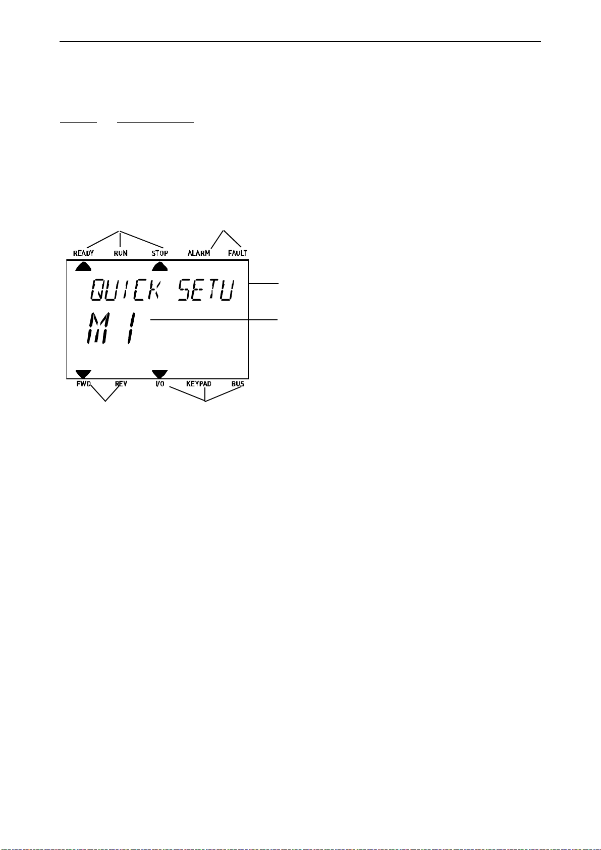
User interfaces vacon • 49
9167.emf
Indicators:
Status
Indicators:
Alarm, Fault
Indicators:
Direction
Indicators:
Control place
Group or parameter
name
Menu location
5.1.5 text keypad
You can also choose a so-called
Text keypad
for your user interface. It has mainly the same func-
tionalities as the graphical keypad although some of these are somewhat limited.
5.1.5.1 Keypad display
The keypad display indicates the status of the motor and the drive and any irregularities in motor or
drive functions. On the display, the user sees information about the drive and
his present
location in
the menu structure and the item displayed. If the text on the text line is too long to fit in the display,
the text will scroll from left to right to reveal the whole text string.
Local contacts: https://www.danfoss.com/en/contact-us/contacts-list/
Page 50
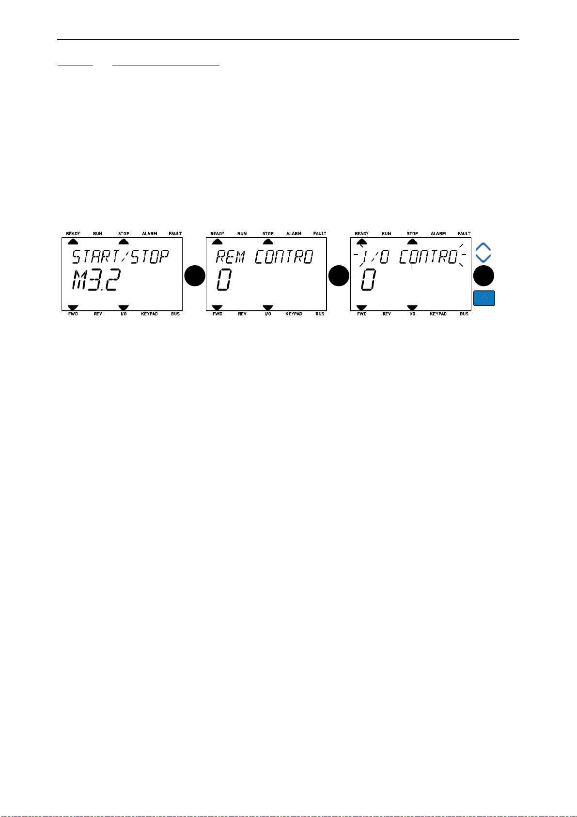
vacon • 50 User interfaces
OK OK OK
BACK
RESET
9168.emf
5.1.5.2 Using the text keypad
Editing values
Change value of a parameter following the procedure below:
1. Locate the parameter.
2. Enter the Edit mode by pressing OK.
3. Set new value with the arrow buttons up/down. You can also move from digit to digit with the
arrow buttons left/right if the value is numerical and change then the value with the arrow buttons up/down.
4. Confirm change with OK button or ignore change by returning to previous level with Back/
Reset button.
Figure 20. Editing values
Resetting fault
Instructions for how to reset a fault can be found in chapter 8 on page 183.
Function button
The FUNCT button is used for four functions:
Control places
The
control place
place has its own parameter for selecting the frequency reference source. The
is always the keypad. The
is the source of control where the drive can be started and stopped. Every control
Local control place
Remote control place
is determined by parameter P3.2.1 (I/O or Field-
bus). The selected control place can be seen on the status bar of the keypad.
Remote control place
I/O A, I/O B and Fieldbus can be used as remote control places. I/O A and Fieldbus have the lowest
priority and can be chosen with parameter P3.2.1
(Rem Control Place)
. I/O B, again, can bypass the
remote control place selected with parameter P3.2.1 using a digital input. The digital input is selected with parameter P3.5.1.7
(I/O B Ctrl Force)
.
Local control
Keypad is always used as control place while in local control. Local control has higher priority than
remote control. Therefore, if, for example, bypassed by parameter P3.5.1.7 through digital input
while in
Remote
, the control place will still switch to Keypad if
Local
is selected. Switching between
Local and Remote Control can be done by pressing the FUNCT-button on the keypad or by using the
"Local/Remote" (ID211) parameter.
Local contacts: https://www.danfoss.com/en/contact-us/contacts-list/
Page 51
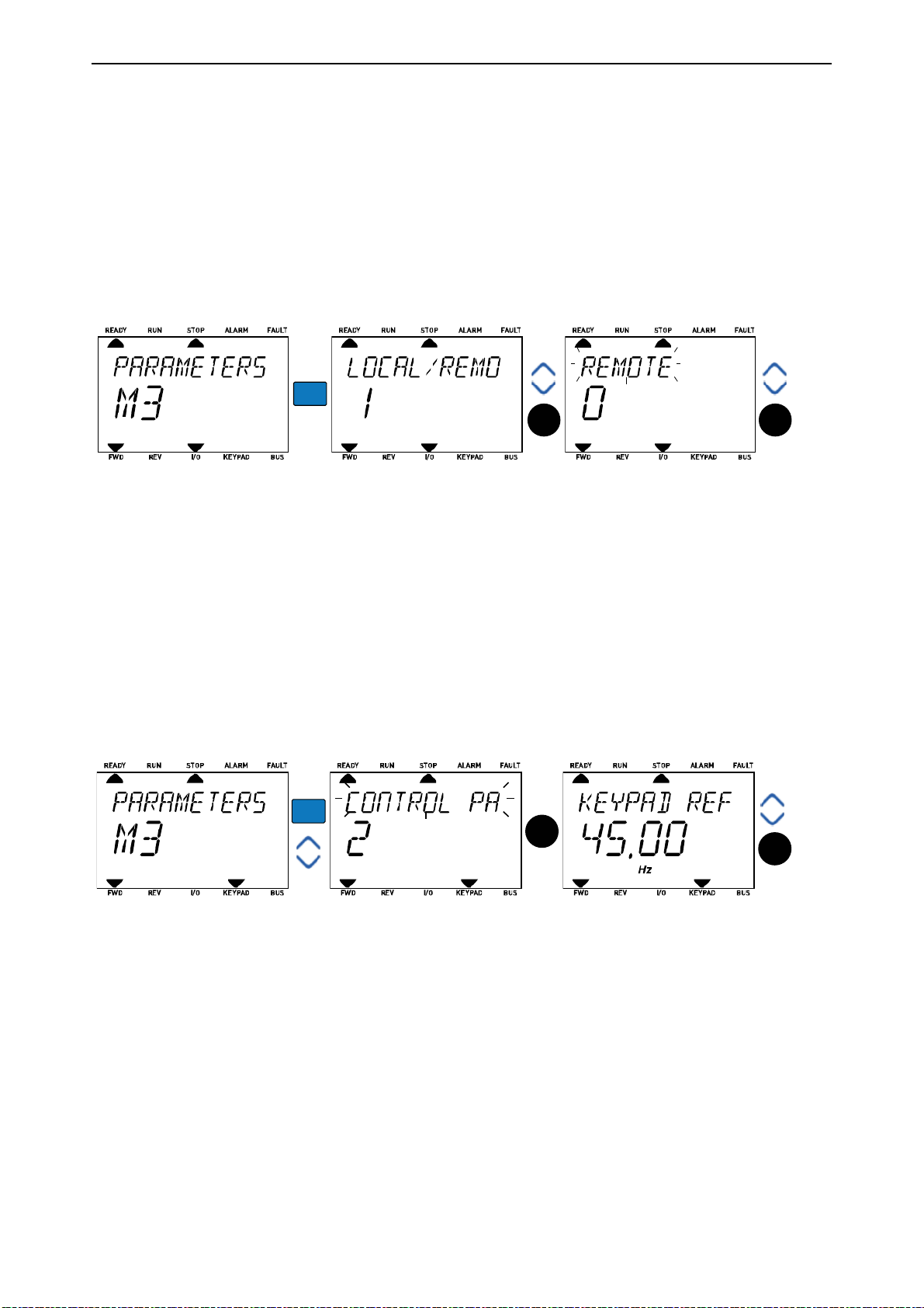
User interfaces vacon • 51
FUNCT
OK OK
9169.emf
9170.emf
FUNCT
OK
OK
Changing control places
Change of control place from
Remote
to
Local
(keypad).
1. Anywhere in the menu structure, push the FUNCT button.
2. Using the arrow buttons, select Local/Remote and confirm with the OK button.
3. On the next display, select Local or Remote and again confirm with the OK button.
4. The display will return to the same location as it was when the
FUNCT
button was pushed.
However, if the Remote control place was changed to Local (Keypad) you will be prompted for
keypad reference.
Figure 21. Changing control places
Accessing the control page
The
Control page
is meant for easy operation and monitoring of the most essential values.
1. Anywhere in the menu structure, push the
2. Push the
Arrow up
or the
Arrow down
FUNCT
button.
button to select
Control page
and confirm with the OK
button.
3. The control page appears
If keypad control place and keypad reference are selected to be used you can set the
Reference
after having pressed the OK button. If other control places or reference values are
used the display will show Frequency reference which is not editable.
Figure 22. Accessing Control page
Changing direction
Rotation direction of the motor can quickly be changed by applying the FUNCT button.
ing direction
command is not visible in the menu unless the selected control place is
Keypad
NOTE!
Local
Chang-
.
1. Anywhere in the menu structure, push the Funct button.
2. Push the Arrow up or the Arrow down button to select Change direction and confirm with the OK
button.
3. Then choose the direction you wish to run the motor to. The actual rotation direction is blinking.
Confirm with the OK button.
4. The rotation direction changes immediately and the arrow indication in the status field changes.
Local contacts: https://www.danfoss.com/en/contact-us/contacts-list/
Page 52

vacon • 52 User interfaces
Quick edit
Through the
Quick edit
functionality you can quickly access the desired parameter by entering the
parameter’s ID number.
1. Anywhere in the menu structure, push the FUNCT button.
2. Push the Arrow up or the Arrow down buttons to select Quick Edit and confirm with the OK button.
3. Then enter the ID number of parameter or monitoring value you wish to access. Press OK button to confirm.
4. Requested Parameter/Monitoring value appears on the display (in editing/monitoring mode.)
Local contacts: https://www.danfoss.com/en/contact-us/contacts-list/
Page 53

User interfaces vacon • 53
5.2 VACON® live
VACON® Live is a PC tool for commissioning and maintenance of the VACON® 10, VACON® 20, and
VACON® 100 AC drives). You can download VACON® Live from www.vacon.com.
The VACON® Live PC tool includes these functions.
• Parametrisation, monitoring, drive info, data logger, etc.
• The software download tool VACON® Loader
• RS-422 and Ethernet support
• Windows XP, Vista 7 and 8 support
• 17 languages: English, German, Spanish, Finnish, French, Italian, Russian, Swedish, Chinese,
Czech, Danish, Dutch, Polish, Portuguese, Romanian, Slovak and Turkish You can make the connection between the AC drive and the PC tool with the black USB/RS-422 cable from VACON or the
VACON® 100 Ethernet cable. The RS-422 drivers are installed automatically during the installation
of VACON® Live. After you installed the cable, VACON® Live finds the connected drive automatically.
See more on how to use VACON® Live in the help menu of the program.
Local contacts: https://www.danfoss.com/en/contact-us/contacts-list/
Page 54

vacon • 54 User interfaces
5.3 Menu structure
Click on and select the item you wish to receive more information about (electronic manual).
Table 15. Keypad menus
Quick setup See chapter 4.
Monitor Multi-monitor*
Trend curve*
Basic
I/O
Extras/Advanced
Timer functions
PID Controller
ExtPID controller
Mainten. counters
Fieldbus data
Solar
Parameters See chapter 7.
Diagnostics Active faults
Reset faults
Fault history
Total counters
Trip counters
Software info
I/O and hardware
Basic I/O
Slot D
Slot E
Real time clock
Power unit settings
Keypad
RS-485
Ethernet
User settings Language selections
Application selection
Parameter backup*
Drive name
Favorites
*
See chapter .
User levels See chapter 5.3.8.
*. Not available in text keypad
Local contacts: https://www.danfoss.com/en/contact-us/contacts-list/
Page 55

User interfaces vacon • 55
Main Menu
0
Quick Setup
( 17 )
0
Parameters
( 12 )
0
ID: M1
STOP READY I/O
( 5 )
Monitor
0
0
0
0
Monitor
Multimonitor
(13)
Basic
(13)
Timer functions
(10)
STOP READY I/O
ID: M2.1
0.0rpm
STOP READY I/O
Multimonitor
0.00 Hz
ID25 FreqReference
Output Freq
0.00Hz
Motor Curre
0.00A
Motor Torqu e
0.00%
Motor Volta ge
Motor Speed
Motor Temper aUnit TemperaDC-link volt
20.0 Hz
FreqReferen c
0.0V
0.0V 81.9°C 0.0%
ID:1 M2.1.1.1
STOP Ready I/O
FreqReference
Output frequency
Motor Power
FreqReference
Motor Speed
Motor Current
Motor Torque
0.00 Hz
10.00 Hz
0.00 rpm
0.00 A
0.00 %
0.00 %
OK OK
OKOK
9171.emf
5.3.1 Quick setup
In the Quick Setup parameter group you will find the different wizards of the VACON® 100 X Solar
Pump Application. More detailed information on the parameters of this group you will find in chapter 4.
5.3.2 Monitor
Multi-monitor
NOTE:
This menu is not available in text keypad.
On the multi-monitor page, you can collect four to nine values that you wish to monitor.
Change the monitored value by activating the value cell (with arrow buttons left/right) and clicking
OK. Then choose a new item on the Monitoring values list and click OK again. More detailed information on the monitor items can be found in chapter 6.
Trend curve
The
Trend Curve
Basic
The basic monitoring values are the actual values of selected parameters and signals as well as
statuses and measurements.
I/O
Statuses and levels of various input and output signal values can be monitored here.
Extras/Advanced
Monitoring of different advanced values, e.g. fieldbus values.
Timer functions
Monitoring of timer functions and the Real Time Clock.
PID Controller
Figure 23. Multi-monitoring page
feature is a graphical presentation of two monitor values at a time.
Monitoring of PID controller values.
External PID Controller
Local contacts: https://www.danfoss.com/en/contact-us/contacts-list/
Page 56

vacon • 56 User interfaces
Monitoring of external PID controller values.
Maintenance counters
Monitoring of values related to Maintenance counters.
Fieldbus data
Fieldbus data shown as monitor values for debugging purposes at e.g. fieldbus commissioning.
Solar
Monitoring of values related to Solar specific application.
Local contacts: https://www.danfoss.com/en/contact-us/contacts-list/
Page 57

User interfaces vacon • 57
5.3.3 Parameters
Through this submenu, you can reach the application parameter groups and parameters. More information on parameters in chapter 7.
5.3.4 Diagnostics
Under this menu, you can find
fo.
Active faults, Reset faults, Fault history, Counters
5.3.4.1 Active faults
Table 16.
Menu Function Note
Active faults When a fault/faults appear(s), the
display with the name of the fault
starts to blink. Press OK to return
to the Diagnostics menu. The
Active faults
submenu shows the
number of faults. Select the fault
and push OK to see the fault-time
data.
5.3.4.2 Reset faults
Table 17.
Menu Function Note
Reset faults In this menu you can reset faults.
For closer instructions, see chapter 8.
and
Software in-
The fault remains active until it is
cleared with the Reset button (push
for 2 s) or with a reset signal from the
I/O terminal or fieldbus or by choosing
Reset faults
(see below).
The memory of active faults can
store the maximum of 10 faults in
the order of appearance.
CAUTION!
Remove external Control
signal before resetting the fault to
prevent unintentional restart of the
drive.
5.3.4.3 Fault history
Table 18.
Menu Function Note
Fault history 40 latest faults are stored in the
Fault history.
Entering the Fault history and clicking OK on the selected fault shows
the fault time data (details).
Local contacts: https://www.danfoss.com/en/contact-us/contacts-list/
Page 58

vacon • 58 User interfaces
5.3.4.4 Total counters
Table 19. Diagnostics menu, Total counters parameters
Code Parameter Min Max Unit Default ID Description
Amount of energy taken from
supply network. No reset.
NOTE FOR TEXT KEYPAD:
The highest energy unit
V4.4.1 Energy counter Varies 2291
V4.4.3
V4.4.4
V4.4.5
V4.4.6
V4.4.7
V4.4.8
V4.4.9
V4.4.10
V4.4.11
V4.4.12
V4.4.13
V4.4.14
V4.4.15
Operating time
(graphical keypad)
Operating time
(text keypad)
Operating time
(text keypad)
Operating time
(text keypad)
Run time
(graphical keypad)
Run time
(text keypad)
Run time
(text keypad)
Run time
(text keypad)
Power on time
(graphical keypad)
Power on time
(text keypad)
Power on time
(text keypad)
Power on time
(text keypad)
Start command
counter
a d hh:min 2298 Control unit operating time
a
d
hh:min:ss
a d hh:min 2293 Motor running time
a
d
hh:min:ss
a d hh:min 2294
a Power on time in total years
d Power on time in total days
hh:min:ss
shown on the standard keypad is MW. Should the
counted energy exceed 999.9
MW, no unit is shown on the
keypad.
Control unit operating time in
total years
Control unit operating time in
total days
Control unit operating time in
hours, minutes and seconds
Motor running time in total
years
Motor running time in total
days
Motor running time in hours,
minutes and seconds
Amount of time the power
unit has been powered so far.
No reset.
Power on time in hours, minutes and seconds
The number of times the
2295
power unit has been started.
Local contacts: https://www.danfoss.com/en/contact-us/contacts-list/
Page 59

User interfaces vacon • 59
5.3.4.5 Trip counters
Table 20. Diagnostics menu, Trip counters parameters
Code Parameter Min Max Unit Default ID Description
Resettable energy counter.
NOTE: The highest energy
unit shown on the standard
keypad is MW. Should the
counted energy exceed 999.9
MW, no unit is shown on the
keypad.
P4.5.1 Energy trip counter Varies 2296
P4.5.3
P4.5.4
P4.5.5
P4.5.6
Operating time
(graphical keypad)
Operating time
(text keypad)
Operating time
(text keypad)
Operating time
(text keypad)
a d hh:min 2299 Resettable. See P4.5.1.
a Operating time in total years
d Operating time in total days
hh:min:ss
To reset the counter:
Standard text keypad:
Apply a long (4 s) push on the
OK button.
Graphical keypad:
Push OK once. Reset
counter page will appear.
Push OK once again.
Operating time in hours,
minutes and seconds
5.3.4.6 Software info
Table 21. Diagnostics menu, Software info parameters
Code Parameter Min Max Unit Default ID Description
V4.6.1
V4.6.2
V4.6.3
V4.6.4 System load 0 100 % 2300 Load on control unit CPU.
V4.6.5
V4.6.6 Application ID Application code.
V4.6.7 Application version
Software package
(graphical keypad)
Software package ID
(text keypad)
Software package
version
(text keypad)
Application name
(graphical keypad)
Code for software identification
Name of application.
Local contacts: https://www.danfoss.com/en/contact-us/contacts-list/
Page 60

vacon • 60 User interfaces
5.3.5 I/O and hardware
Various options-related settings are located in this menu. Note that the values in this menu are raw
values i.e. not scaled by the application.
5.3.5.1 Basic I/O Monitor here the statuses of inputs and outputs.
Table 22. I/O and Hardware menu, Basic I/O parameters
Code Parameter Min Max Unit Default ID Description
V5.1.1 Digital input 1 0 1 0 Status of digital input signal
V5.1.2 Digital input 2 0 1 0 Status of digital input signal
V5.1.3 Digital input 3 0 1 0 Status of digital input signal
V5.1.4 Digital input 4 0 1 0 Status of digital input signal
V5.1.5 Digital input 5 0 1 0 Status of digital input signal
V5.1.6 Digital input 6 0 1 0 Status of digital input signal
Shows the selected (with
jumper) mode for Analogue
V5.1.7 Analogue input 1 mode 1 3 3
V5.1.8 Analogue input 1 0 100 % 0.00
V5.1.9 Analogue input 2 mode 1 3 3
V5.1.10 Analogue input 2 0 100 % 0.00
V5.1.11
V5.1.12 Analogue output 1 0 100 % 0.00
V5.1.13 Relay output 1 0 1 0 Status of relay output signal
V5.1.14 Relay output 2 0 1 0 Status of relay output signal
V5.1.15 Relay output 3 0 1 0 Status of relay output signal
Analogue output 1
mode
1 3 1
input signal
1 = 0...20 mA
3 = 0...10 V
Status of analogue input signal
Shows the selected (with
jumper) mode for Analogue
input signal
1 = 0...20 mA
3 = 0...10 V
Status of analogue input signal
Shows the selected (with
jumper) mode for Analogue
output signal
1 = 0...20 mA
3 = 0...10 V
Status of analogue output
signal
Local contacts: https://www.danfoss.com/en/contact-us/contacts-list/
Page 61

User interfaces vacon • 61
GRAPHICAL KEYPAD
Parameter name (= Function)
Parameter name (= Function)
Parameter value (= selected digital input)
Parameter value (= selected digital input)
5.3.5.2 Option board slots The parameters of this group depend on the option board installed. If no option board is placed in
slots D or E, no parameters are visible.
As an option board is removed, info text 39
Table 23. Option board-related parameters
Device removed
will appear on the display.
Menu Function Note
Slot D Settings Option board related settings.
Monitoring Monitor option board-related info.
Slot E Settings Option board related settings.
Monitoring Monitor option board-related info.
5.3.5.3 Programming of digital and analogue inputs The programming of inputs in the VACON® 100X Solar Pump Application is very flexible. The avail-
able inputs on the standard and optional I/O can be used for various functions according to the operator's choice.
The available I/O can be expanded with optional boards to be inserted in board slots D and E. More
information about the installation of optional boards you will find in the VACON® 100 X Installation
manual.
5.3.5.4 Digital inputs
The applicable functions for digital inputs are arranged as parameters in parameter group M3.5.1.
The value given to the parameter is a reference to the digital input you choose to use for the function. The list of functions that you can assign to the available digital inputs is presented on Digital
Inputs group.
Example
Figure 24.
Local contacts: https://www.danfoss.com/en/contact-us/contacts-list/
Page 62

vacon • 62 User interfaces
OK
OK
9260.emf
BACK
RESET
BACK
RESET
Given the standard I/O board compilation on the VACON® 100 AC drive, there are 6 digital inputs
available (Slot A terminals 8, 9, 10, 14, 15 and 16). In the programming view, these inputs are referred to as follows:
Table 24.
Input type
(Graphical keypad)
DigIN dI A. 1 Digital input #1 (terminal 8) on board
DigIN dI A. 2 Digital input #2 (terminal 9) on board
DigIN dI A. 3 Digital input #3 (terminal 10) on
DigIN dI A. 4 Digital input #4 (terminal 14) on
DigIN dI A. 5 Digital input #5 (terminal 15) on
DigIN dI A. 6 Digital input #6 (terminal 16) on
In the example Figure 24, the function
P3.5.1.11, is by default given the value
means that the function
Input type
(Text keypad)
External fault close
DigIN SlotA.3
External fault close
DI3 (terminal 10).
This is what is shown in the parameter list.
Slot Input # Explanation
in Slot A (standard I/O board).
in Slot A (standard I/O board).
board in Slot A (standard I/O board).
board in Slot A (standard I/O board).
board in Slot A (standard I/O board).
board in Slot A (standard I/O board).
located in menu M3.5.1 as parameter
(graphical keypad) or
dI A.3
(text keypad). This
is now controlled with a digital signal to digital input
Code Parameter Default ID Description
P3.5.1.11 External fault close DigIN SlotA.3 405
FALSE = OK
TRUE = External fault
Assume you need to change the selected input. Instead of DI3 you wish to use DI6 (terminal 16) on
the standard I/O. Do as instructed here:
Figure 25. Programming digital inputs with graphical keypad
Local contacts: https://www.danfoss.com/en/contact-us/contacts-list/
Page 63

User interfaces vacon • 63
Figure 26. Programming digital inputs with text keypad
Table 25. Programming digital inputs
PROGRAMMING INSTRUCTIONS
Graphical keypad Text keypad
1. Select the parameter and push the
right
button.
2. You are now in the
value
DigIN SlotA.
Edit
mode as the slot
is blinking and under-
Arrow
lined. (Should you have more digital inputs
available in your I/O, for example, through
inserted option boards in slots D or E, they
can also be selected here.).
3. Push the
Arrow right
button again to acti-
vate the terminal value 3.
4. Push the
Arrow up
button three times to
change the terminal value to 6. Confirm
with OK button.
5. NOTE! If the digital input DI6 was already
used for some other function a message is
displayed. You might then want to change
either of these selections.
1. Select the parameter and push the OK button.
2. You are now in the
Edit
mode as the letter d
is blinking. (Should you have more digital
inputs available in your I/O, for example,
through inserted option boards in slots D or
E, they can also be selected here.).
3. Push the
Arrow right
button to activate the
terminal value 3. The letter d stops blinking.
4. Push the
Arrow up
button three times to
change the terminal value to 6. Confirm with
OK button.
5. NOTE! If the digital input DI6 was already
used for some other function a message will
scroll through the display. You might then
want to change either of these selections.
Now, the function
External fault close
is controlled with a digital signal to digital input DI6 (terminal
16).
The function is not assigned to any terminal, or, the the input is set to be always
NOTE!
FALSE, if its value is
is the default value of the majority of parameters in group M3.5.1.
DigIN Slot0.1
(graphical keypad) or
On the other hand, some inputs have been by default set to be always TRUE. Their
value shows
Local contacts: https://www.danfoss.com/en/contact-us/contacts-list/
DigIN Slot0.2
(graphical keypad) or
dI 0.2
dI 0.1
(text keypad). This
(text keypad).
Page 64

vacon • 64 User interfaces
GRAPHICAL KEYPAD
Parameter name
Parameter name
Parameter value (= selected analogue input)
TEXT KEYPAD
Parameter value (= selected analogue input)
Also
NOTE!
5.3.5.5 Analogue inputs
Time Channels
page 115.
can be assigned to digital inputs. See more information on
The target input for the analogue frequency reference signal can also be chosen from the available
analogue inputs.
Given the standard I/O terminals on the VACON® 100 X AC drive, there are 2 analogue inputs available. In the programming view, these inputs are referred to as follows:
Input type
(Graphical keypad)
In the example Figure 27, the parameter
eter code P3.5.2.1.1, is by default given the value
keypad). This means that the target input for the analogue frequency reference signal AI1 is now
the analogue input in terminals 2/3. Whether the signal is voltage or current, must be determined
with the
Figure 27.
Table 26. Programming analogue inputs
Input type
(Text keypad)
AnIN AI A. 1 Analogue input #1 (terminals 2/3) on
AnIN AI A. 2 Analogue input #2 (terminals 4/5) on
dip switches
. See the Installation manual for more information.
Slot Input # Explanation
board in Slot A (standard I/O terminals).
board in Slot A (standard I/O terminals).
AI1 signal selection
AnIN SlotA.1
located in menu M3.5.2.1 with param-
(graphical keypad) or
AI A.1
(text
This is what is shown in the parameter list on page 100:
Local contacts: https://www.danfoss.com/en/contact-us/contacts-list/
Page 65
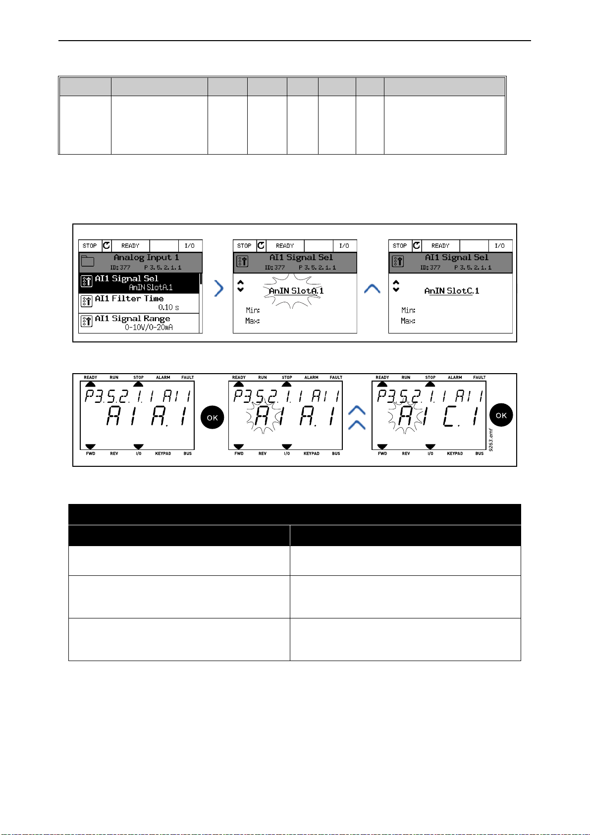
User interfaces vacon • 65
9264.emf
Code Parameter Min Max Unit Default ID Description
Connect the AI1 signal to the
analogue input of your choice
377
with this parameter.
Programmable. See
page 100.
P3.5.2.1.1 AI1 signal selection
AnIN
SlotA.1
Assume you need to change the selected input. Instead of AI1 you wish to use the analogue input on
your option board in slot D. Do as instructed here:
Figure 28. Programming analogue inputs with graphical keypad
Figure 29. Programming analogue inputs with text keypad
PROGRAMMING INSTRUCTIONS
Graphical keypad Text keypad
1. Select the parameter and push the
right
button.
2. You are now in the
value
AnIN SlotA.
Edit
mode as the slot
is blinking and under-
lined.
3. Push the
the slot value to
Arrow up
AnIN SlotC
button once to change
. Confirm with
OK button.
Arrow
1. Select the parameter and push the OK button.
2. You are now in the
Edit
mode as the letter A
is blinking.
3. Push the
Arrow up
button once to change
the slot value to C. Confirm with OK button.
Local contacts: https://www.danfoss.com/en/contact-us/contacts-list/
Page 66

vacon • 66 User interfaces
5.3.5.6 Descriptions of signal sources
Table 27. Descriptions of signal sources
Source Function
Digital inputs:
A digital signal can be forced to a constant FALSE or TRUE
state using this functionality.
For example, some signals have been set to be always in
TRUE state by manufacturer, e.g parameter P3.5.1.15 (Run
enable). Unless changed, Run enable signal is always on.
Slot0.#
SlotA.#
SlotD.# Number (#) corresponds to digital input in slot D.
# = 1: Always FALSE
# = 2-10: Always TRUE
Analogue inputs (used for testing purposes):
# = 1: Analogue input = 0% signal strength
# = 2: Analogue input = 20% signal strength
# = 3: Analogue input = 30% signal strength
etc.
# = 10: Analogue input = 100% signal strength
Number (#) corresponds to digital input in slot A(Standard
terminals).
SlotE.# Number (#) corresponds to digital input in slot E.
TimeChannel.#
Fieldbus CW.# Number (#) refers to Control Word bit number.
FieldbusPD.# Number (#) refers to Process Data 1 bit number.
Number (#) corresponds to: 1=Time Channel1, 2=Time
Channel2, 3=Time Channel3
5.3.5.7 Default assignments of digital and analogue inputs in VACON® 100 application
Digital and analogue inputs are assigned certain functions by the factory. In this application, the default assignments are:
Table 28. Default assignments of inputs
Input Terminal(s) Reference Assigned function Parameter code
DI1 8 A.1 Control signal 1 A P3.5.1.1
DI2 9 A.2 Control signal 2 A P3.5.1.2
DI3 10 A.3 External fault close P3.5.1.11
DI4 14 A.4 Preset Freq Sel0 P3.5.1.21
DI5 15 A.5 Preset Freq Sel1 P3.5.1.22
DI6 16 A.6 External fault close P3.5.1.13
AI1 2/3 A.1 AI1 signal selection P3.5.2.1.1
AI2 4/5 A.2 AI2 signal selection P3.5.2.2.1
Local contacts: https://www.danfoss.com/en/contact-us/contacts-list/
Page 67
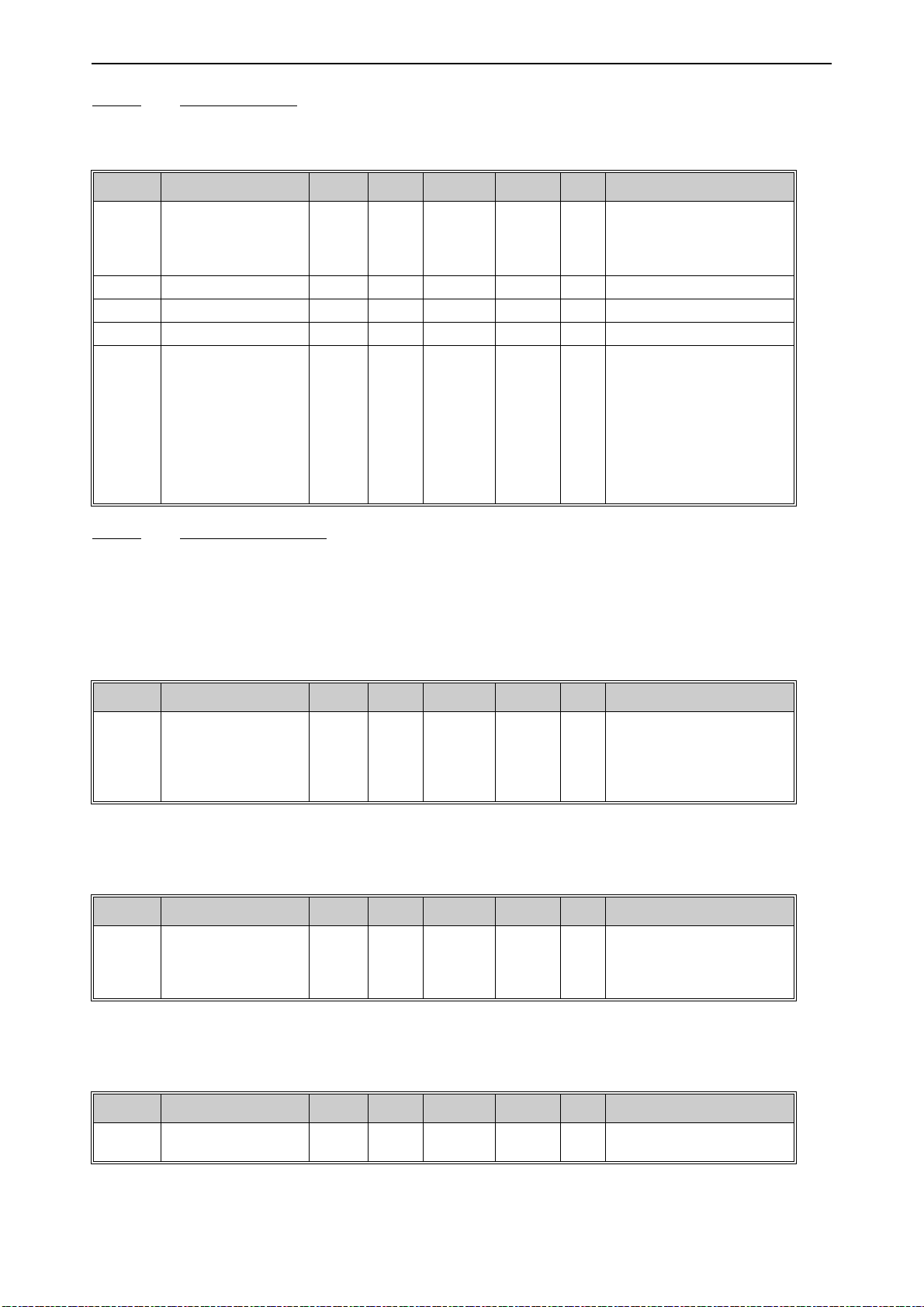
User interfaces vacon • 67
5.3.5.8 Real time clock
Table 29. I/O and Hardware menu, Real time clock parameters
Code Parameter Min Max Unit Default ID Description
Status of battery.
V5.5.1 Battery state 1 3 2 2205
P5.5.2 Time hh:mm:ss 2201 Current time of day
P5.5.3 Date dd.mm. 2202 Current date
P5.5.4 Year yyyy 2203 Current year
P5.5.5 Daylight saving 1 4 1 2204
1 = Not installed
2 = Installed
3 = Change battery
Daylight saving rule
1 = Off
2 = EU; Starts on last Sunday
in March, ends last Sunday in
October
3 = US; Start on 2nd Sunday
in March, ends on 1st Sunday
in November
4 = Russia (permanent)
5.3.5.9 Power unit settings
Fan control
The fan operates in speed-controlled mode. The speed is controlled according to the drive’s internal logic that receives data from temperature measurements.
Table 30. Power unit settings, Fan control
Code Parameter Min Max Unit Default ID Description
If enabled, the fan will stop in
5 minutes when the drive is
V5.6.1.3 Fan stop 0 1 1 826
in Ready state.
0 = Disabled
1 = Enabled
Brake chopper
Table 31. Power unit settings, Brake chopper
Code Parameter Min Max Unit Default ID Description
0 = Disabled
V5.6.2.1 Brake chopper mode 0 3 0
1 = Enabled (Run)
2 = Enabled (Run & Stop)
3 = Enabled (Run, no testing)
Sine filter
Table 32. Power unit settings, Sine filter
Code Parameter Min Max Unit Default ID Description
V5.6.4.1 Sine filter 0 1 0
Local contacts: https://www.danfoss.com/en/contact-us/contacts-list/
0 = Disabled
1 = Enabled
Page 68

vacon • 68 User interfaces
5.3.5.10 Keypad
Table 33. I/O and Hardware menu, Keypad parameters
Code Parameter Min Max Unit Default ID Description
Time after which the display
P5.7.1 Timeout time 0 60 min 0
P5.7.2 Default page 0 4 0
P5.7.3 Menu index
P5.7.4
P5.7.5 Backlight time 0 60 min 5
Contrast
*
30 70 % 50
returns to page defined with
parameter P5.7.2.
0 = Not used
The page the keypad shows
when the drive is powered on
or when the time defined
with P5.7.1 has expired. If the
value is set to 0 the page last
visited is shown.
0 = None
1 = Enter menu index
2 = Main menu
3 = Control page
4 = Multimonitor
Set menu index for desired
page and activate with
parameter P5.7.2 = 1.
Set contrast of the display
(30...70%).
Set the time until the backlight of the display turns off
(0...60 min). If set to 0 s,
backlight is always on.
*. Only available with graphical keypad
Local contacts: https://www.danfoss.com/en/contact-us/contacts-list/
Page 69

User interfaces vacon • 69
5.3.5.11 Fieldbus Parameters related to different fieldbus boards can also be found in the
I/O and Hardware
menu.
These parameters are explained in more detail in the respective fieldbus manual.
Table 34.
Submenu level 1 Submenu level 2 Submenu level 3 Submenu level 4
RS-485 Common settings Protocol
Ethernet Common settings IP address mode
IP address
Subnet mask
Default gateway
MAC address
NA
NA
NA
NA
NA
NA
Modbus/TCP Common settings Connection limit
Slave address
Communication timeout
BacNet IP Settings Instance number
Communication timeout
Protocol in use
BBMD IP
BBMD port
Time to live
Monitoring FB protocol status
Communication status
Actual instance
Control Word
Status Word
Local contacts: https://www.danfoss.com/en/contact-us/contacts-list/
Page 70

vacon • 70 User interfaces
5.3.6 User settings
Table 35. User settings menu, General settings
Code Parameter Min Max Unit Default ID Description
P6.1 Language selections Varies Varies Varies 802
P6.2 Application selection 801
M6.5 Parameter backup See chapter 5.3.6.1 below.
P6.7 Drive name Give name of drive if needed.
Depends on language package.
5.3.6.1 Parameter backup
Table 36. User settings menu, Parameter backup parameters
Code Parameter Min Max Unit Default ID Description
Restores default parameter
P6.5.1
P6.5.2
P6.5.3 Restore from keypad*
B6.5.4 Save to Set 1
B6.5.5 Restore from Set 1
B6.5.6 Save to Set 2
B6.5.7 Restore from Set 2
Restore factory
defaults
Save to keypad
*
0 1 0
values and initiates the
831
Startup Wizard when activated
Save parameter values to
keypad to e.g. copy them to
another drive.
0 = No
1 = Yes
Load parameter values from
keypad to the drive.
Store a customised parameter set (all parameters
included in the application)
Load the customised parameter set to the drive.
Store another customised
parameter set (all parameters included in the application)
Load the customised parameter set 2 to the drive.
*. Only available with graphical keypad
Local contacts: https://www.danfoss.com/en/contact-us/contacts-list/
Page 71
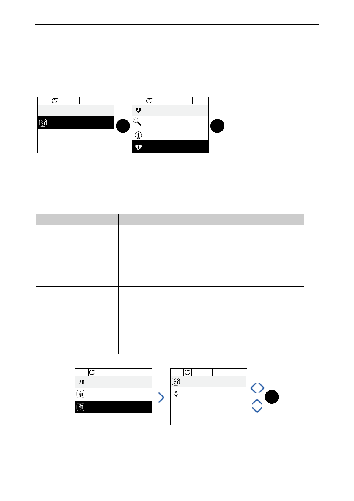
User interfaces vacon • 71
0
Motor Nom Freq
50.00 Hz
Favorites
STOP READY I/O
0
Help
Motor Nom Freq
STOP READY I/O
Monitor
Rem from favorites
OK OK
9172.emf
STOP READY KeypadALARM
0
ID:2362 P8.2
User levels
User level
Normal
Access code
00000
STOP READY I/OALARM
00000
Min:0
Max:9
ID:2362 P8.2
Access code
OK
9173.emf
5.3.7 Favorites
NOTE:
This menu is not available in text keypad.
Favorites are typically used to collect a set of parameters or monitoring signals from any of the keypad menus. You can add items or parameters to the Favorites folder, see chapter .
To remove an item or a parameter from the Favorites folder, do the following:
5.3.8 User levels
User level parameters are intended to restrict the visibility of parameters and to prevent unauthorized and inadvertent parameterization on the keypad.
Table 37. User level parameters
Code Parameter Min Max Unit Default ID Description
1 = Normal; All menus visible
in the Main menu
2 = Monitoring; Only Monitor,
Favorites and User Levels
P8.1 User level 1 3 1 1194
P8.2 Access code 0 99999 0 2362
menus are visible in the main
menu
3 = Favorites; Only Favorites
and User Levels menus are
visible in the Main menu
If set to other value than 0
before switching to monitoring when e.g. user level Nor-
mal is active, the access
code will be asked when trying to switch back to Nor-
mal. Can therefore be used
to prevent unauthorized
parameterization on the keypad.
Local contacts: https://www.danfoss.com/en/contact-us/contacts-list/
Page 72
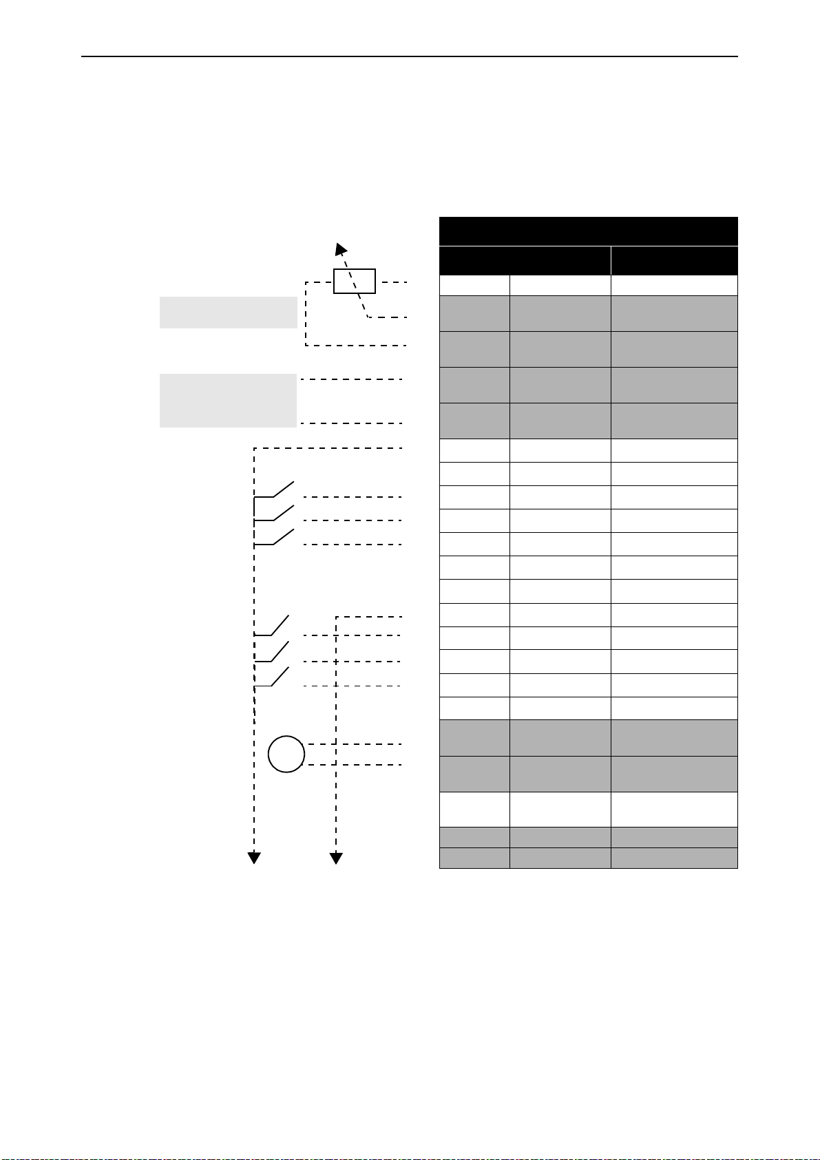
vacon • 72 User interfaces
Reference
potentiometer 1...10 k
Ω
Remote reference
4...20 mA/0...10 V
mA
5.4 Example of control connections
The terminals of the
shadowed background are assigned for signals with optional functions selectable with DIP switches. See more information in VACON® 100X Installation Manual.
Table 38. Control I/O terminal signals and connection example.
Standard I/Os
and the
Relays
are described below. The terminals shown on
Standard I/O
Terminal Signal
1 +10 Vref Reference output
AI1+
2
AI1-
3
AI2+
4
AI2-
5
24Vout 24V aux. voltage
6
GND I/O ground
7
DI1 Digital input 1
8
DI2 Digital input 2
9
10
11
12
13
14
15
16
17
18
19
30 +24 Vin
DI3 Digital input 3
CM
24Vout 24V aux. voltage
GND I/O ground
DI4 Digital input 4
DI5 Digital input 5
DI6 Digital input 6
CM Common for DI1-DI6*
AO1+
AO-/GND
A RS485 Serial bus, negative
B RS485 Serial bus, positive
Analogue input,
voltage or current
Analogue input common
Analogue input,
voltage or current
Analogue input common
Common for DI1-DI6
Analogue output,
voltage or current
Analogue output common
24V auxiliary input
voltage
*
*. Can be isolated from ground, see
VACON® 100X Installation Manual.
Local contacts: https://www.danfoss.com/en/contact-us/contacts-list/
Page 73
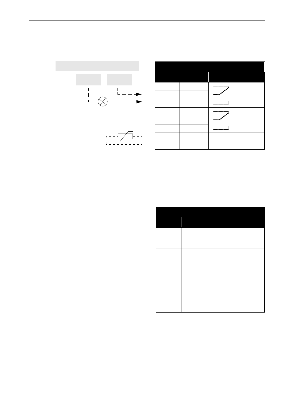
User interfaces vacon • 73
From
standard I/O
From term.
#13
From term.
#6
RUN
5.4.1 Relay and thermistor input terminals
Table 39. I/O terminal signals for relay and thermistor terminals and connection example.
Relays and thermistor
Terminal Signal
21
22
23
24
25
26
28
29
RO1/1
RO1/2
RO1/3
RO2/1
RO2/2
RO2/3
TI1+
TI1-
Relay output 1
Relay output 2
Thermistor input
5.4.2 Safe Torque off (STO) terminals
For more information on the functionalities of the Safe Torque Off (STO), see VACON® 100X Installation Manual.
Table 40. I/O terminal signals for the STO functions.
Safe Torque Off terminals
Terminal Signal
S1
G1
S2
G2
F+
F-
Isolated digital input 1 (interchangeable polarity);
+24V ±20% 10...15mA
Isolated digital input 2 (interchangeable polarity);
+24V ±20% 10...15mA
Isolated feedback (CAUTION!
Polarity to be respected);
+24V ±20%
Isolated feedback (CAUTION!
Polarity to be respected);
GND
Local contacts: https://www.danfoss.com/en/contact-us/contacts-list/
Page 74

vacon • 74 Monitoring menu
OK
OK
OK
OK
9250.emf
6. M
ONITORING MENU
6.1 Monitor group
VACON® 100 X AC drive provides you with a possibility to monitor the actual values of parameters
and signals as well as statuses and measurements. Some of the values to be monitored are customizable.
6.1.1 Multimonitor
On the multi-monitor page, you can collect four to nine values that you wish to monitor.
6.1.2 Trend curve
The
Trend Curve
Selecting values to monitor starts logging the values. In the Trend curve submenu, you can view the
trend curve, make the signal selections, give the minimum and maximum settings, Sampling interval and choose whether to use Autoscaling or not.
Change values to monitor following the procedure below:
1. Locate the
2. Further enter the menu
3. The current selections to monitor are
the display.
4. Only two values can be monitored as trend curves simultaneously. Select the one of the current
values you wish to change with the arrow buttons and press OK.
5. Browse the list of given monitoring values with the arrow buttons, select the one you wish and
press OK.
6. The trend curve of the changed value can be seen on the display.
feature is a graphical presentation of two monitor values at a time.
Trend curve
menu in the
View trend curve
Monitor
FreqReference
menu and press OK.
by pressing OK again.
and
Motor speed
visible at the bottom of
The
Trend Curve
feature also allows you to halt the progression of the curve and read the exact in-
vidual values.
1. In Trend curve view, select the display with the arrow button up (the frame of the display turns
bold) and press OK at the desired point of the progressing curve. A vertical hairline appears on
the display.
2. The display freezes and the values at the bottom of the display correspond to the location of the
hairline.
3. Use the arrow buttons left and right to move the hairline to see the exact values of some other
location.
Local contacts: https://www.danfoss.com/en/contact-us/contacts-list/
Page 75

Monitoring menu vacon • 75
9251.emf
OK
Table 41. Trend curve parameters
Code Parameter Min Max Unit Default ID Description
Enter this menu to select and
M2.2.1 View Trend curve
monitor values for viewing in
curve form.
P2.2.2 Sampling interval 100 432000 ms 100 2368
Set here the sampling interval.
Used by default for scaling.
P2.2.3 Channel 1 min -214748 1000 -1000 2369
Adjustments might be necessary.
Used by default for scaling.
P2.2.4 Channel 1 max -1000 214748 1000 2370
Adjustments might be necessary.
Used by default for scaling.
P2.2.5 Channel 2 min -214748 1000 -1000 2371
Adjustments might be necessary.
Used by default for scaling.
P2.2.6 Channel 2 max -1000 214748 1000 2372
Adjustments might be necessary.
The selected signal is auto-
P2.2.7 Autoscale 0 1 0 2373
matically scaled between
min and max values if this
parameter is given value 1.
Local contacts: https://www.danfoss.com/en/contact-us/contacts-list/
Page 76

vacon • 76 Monitoring menu
6.1.3 Basic
See Table 42 in which the basic monitoring values are presented.
NOTE!
Only standard I/O board statuses are available in the Monitor menu. Statuses for all I/O board
signals can be found as raw data in the I/O and Hardware system menu.
Check expander I/O board statuses when required in the I/O and Hardware system menu.
Table 42. Basic monitoring menu items
Code Monitoring value Unit Scale ID Description
V2.3.1 Output frequency Hz 0.01 1 Output frequency to motor
V2.3.2 FreqReference Hz 0.01 25 Frequency reference to motor control
V2.3.3 Motor speed rpm 1 2 Motor actual speed in rpm
V2.3.4 Motor current A Varies 3
V2.3.5 Motor torque % 0.1 4 Calculated shaft torque
V2.3.7 Motor shaft power % 0.1 5 Calculated motor shaft power in %
Calculated motor shaft power in kW or hp.
V2.3.8 Motor shaft power kW/hp Varies 73
V2.3.9 Motor voltage V 0.1 6 Output voltage to motor
V2.3.10 DC link voltage V 1 7 Measured voltage in the drive’s DC-link
V2.3.11 Unit temperature °C 0.1 8 Heatsink temperature in °C or °F
V2.3.12 Motor temperature % 0.1 9
V2.3.13 Motor Preheat 1 1228
Units depends on the unit selection parameter.
Calculated motor temperature in percent
of nominal working temperature.
Status of Motor preheat function.
0 = OFF
1 = Heating (feeding DC-current)
Local contacts: https://www.danfoss.com/en/contact-us/contacts-list/
Page 77

Monitoring menu vacon • 77
6.1.4 I/O
Table 43. I/O signal monitoring
Code Monitoring value Unit Scale ID Description
V2.4.1 Slot A DIN 1, 2, 3 1 15
V2.4.2 Slot A DIN 4, 5, 6 1 16
V2.4.3 Slot B RO 1, 2, 3 1 17 Shows the status of relay inputs 1-3 in slot B
V2.4.4 Analogue input 1 % 0.01 59
V2.4.5 Analogue input 2 % 0.01 60
V2.4.6 Analogue input 3 % 0.01 61
V2.4.7 Analogue input 4 % 0.01 62
V2.4.8 Analogue input 5 % 0.01 75
V2.4.9 Analogue input 6 % 0.01 76
V2.4.10 Slot A AO1 % 0.01 81
Shows the status of digital inputs 1-3 in slot
A (standard I/O)
Shows the status of digital inputs 4-6 in slot
A (standard I/O)
Input signal in percent of used range. Slot
A.1 as default.
Input signal in percent of used range. Slot
A.2 as default.
Input signal in percent of used range. Slot
D.1 as default.
Input signal in percent of used range. Slot
D.2 as default.
Input signal in percent of used range. Slot
E.1 as default.
Input signal in percent of used range. Slot
E.2 as default.
Analog output signal in percent of used
range. Slot A (standard I/O)
Local contacts: https://www.danfoss.com/en/contact-us/contacts-list/
Page 78

vacon • 78 Monitoring menu
6.1.5 Extras & advanced
Table 44. Advanced values monitoring
Code Monitoring value Unit Scale ID Description
Bit coded word
B1=Ready
B2=Run
B3=Fault
V2.6.1 DriveStatusWord 1 43
V2.6.2 Ready status 1 78
V2.6.3 Appl.StatusWord1 1 89
V2.6.4 Appl.StatusWord2 1 90
B6=RunEnable
B7=AlarmActive
B10=DC Current in stop
B11=DC Brake Active
B12=RunRequest
B13=MotorRegulatorActive
Bit coded information about ready criteria.
Useful for debugging when the drive is not in
ready status.
Values are visible as checkboxes on graphical keypad. If checked (), the value is
active.
B0: RunEnable high
B1: No fault active
B2: Charge switch closed
B3: DC voltage within limits
B4: Power manager initialized
B5: Power unit is not blocking start
B6: System software is not blocking start
Bit coded statuses of application.
Values are visible as checkboxes on graphical keypad. If checked (), the value is
active.
B0=Interlock 1
B1=Interlock 2
B2=Reserved
B3=Ramp 2 active
B4=Mechanical brake control
B5=I/O A control active
B6=I/O B control active
B7=Fieldbus Control Active
B8=Local control active
B9=PC control active
B10=Preset frequencies active
B11=Inching active
B12=Fire Mode active
B13=Motor Preheat active
B14=Forced stop active
B15=Drive stopped from keypad
Bit coded status of application.
Values are visible as checkboxes on graphical keypad. If checked (), the value is
active.
B0=Acc/Dec prohibited
B1=Motor switch open
B5=Jockey pump active
B6=Priming pump active
B7=Input pressure supervision (Alarm/Fault)
B8=Frost protection (Alarm/Fault)
B9=Autocleaning active
Local contacts: https://www.danfoss.com/en/contact-us/contacts-list/
Page 79

Monitoring menu vacon • 79
Table 44. Advanced values monitoring
Code Monitoring value Unit Scale ID Description
16-bit word where each bit represents the
status of one digital input. 6 digital inputs
V2.6.5 DIN StatusWord1 1 56
V2.6.6 DIN StatusWord2 1 57
V2.6.7 MotCurrent1 deci. 0.1 45
V2.6.8 FreqRef Source 1 1495
V2.6.9 LastActiveFaultCode 1 37
V2.6.10 LastActiveFault ID 1 95
V2.6.11 LastActiveAlarmCode 1 74
V2.6.12 LastActiveAlarm ID 1 94
V2.6.13 MotorRegulat.Status 1 77
from every slot are read. Word 1 starts from
input 1 in slot A (bit0) and goes all the way to
input 4 in slot C (bit15).
16-bit word where each bit represents the
status of one digital input. 6 digital inputs
from every slot are read. Word 1 starts from
input 5 in slot C (bit0) and goes all the way to
input 6 in slot E (bit13).
Motor current monitor value with fixed number of decimals and less filtering. Can be
used e.g. for fieldbus purposes to always get
the right value regardless of frame size, or
for monitoring when less filtering time is
needed for the motor current.
Shows the momentary frequency reference
source.
0=PC
1=Preset Freqs
2=Keypad Reference
3=Fieldbus
4=AI1
5=AI2
6=AI1+AI2
7=PID Controller
8=Motor Potentiom.
9=Joystick
10=Inching
100=Not defined
101=Alarm,PresetFreq
102=Autocleaning
The fault code of latest activated fault that
has not been reset.
The fault ID of latest activated fault that has
not been reset.
The alarm code of latest activated alarm that
has not been reset.
The alarm ID of latest activated alarm that
has not been reset.
Motor limit controller status. Checked = limit
controller is active, Unchecked = limit controller is not active
Local contacts: https://www.danfoss.com/en/contact-us/contacts-list/
Page 80
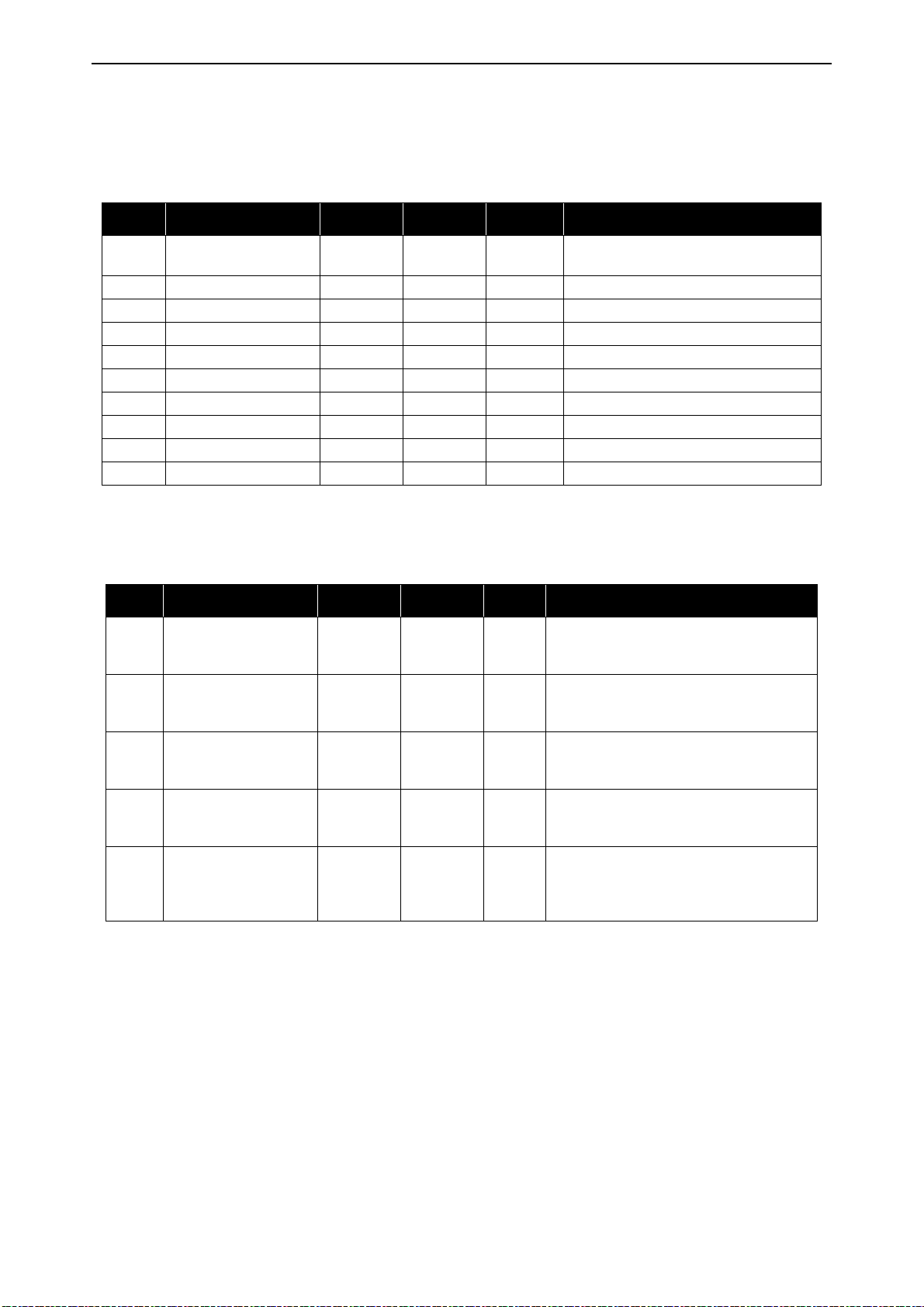
vacon • 80 Monitoring menu
6.1.6 Timer functions
Here you can monitor values of timer functions and the Real Time Clock.
Table 45. Monitoring of timer functions
Code Monitoring value Unit Scale ID Description
V2.7.1 TC 1, TC 2, TC 3 1 1441
V2.7.2 Interval 1 1 1442 Status of timer interval
V2.7.3 Interval 2 1 1443 Status of timer interval
V2.7.4 Interval 3 1 1444 Status of timer interval
V2.7.5 Interval 4 1 1445 Status of timer interval
V2.7.6 Interval 5 1 1446 Status of timer interval
V2.7.7 Timer 1 s 1 1447 Remaining time on timer if active
V2.7.8 Timer 2 s 1 1448 Remaining time on timer if active
V2.7.9 Timer 3 s 1 1449 Remaining time on timer if active
V2.7.10 Real time clock 1450 hh:mm:ss
Possible to monitor the statuses of the
three Time Channels (TC)
6.1.7 PID Controller
Table 46. PID Controller value monitoring
Code Monitoring value Unit Scale ID Description
V2.8.1 PID setpoint Varies
V2.8.2 PID feedback Varies
V2.8.3 PID error Varies
V2.8.4 PID output % 0.01 23
V2.8.5 PID status 1 24
According to
P3.13.1.7
According to
P3.13.1.7
According to
P3.13.1.7
PID controller setpoint value in process
20
units. Process unit is selected with a
parameter.
PID controller feedback value in process
21
units. Process unit is selected with a
parameter.
PID controller error value. Deviation of
22
feedback from setpoint in process units.
Process unit is selected with a parameter.
PID output in percent (0..100%). This value
can be fed e.g. to Motor Control (Frequency
reference) or Analogue output
0=Stopped
1=Running
3=Sleep mode
4=In dead band
Local contacts: https://www.danfoss.com/en/contact-us/contacts-list/
Page 81
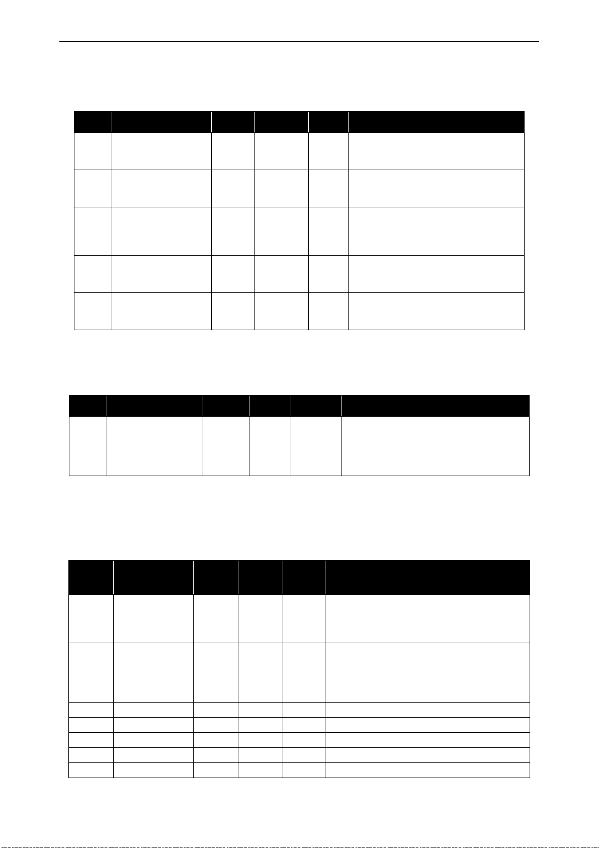
Monitoring menu vacon • 81
6.1.8 ExtPID Controller
Table 47. External PID Controller value monitoring
Code Monitoring value Unit Scale ID Description
V2.9.1 ExtPID setpoint Varies
V2.9.2 ExtPID feedback Varies
V2.9.3 ExtPID error Varies
V2.9.4 ExtPID output % 0.01 86
V2.9.5 ExtPID status 1 87
According to
P3.14.1.10
According to
P3.14.1.10
According to
P3.14.1.10
External PID controller setpoint value in
83
process units. Process unit is selected with
a parameter.
External PID controller feedback value in
84
process units. Process unit is selected with
a parameter.
External PID controller Error value. Deviation of feedback from setpoint in process
85
units. Process unit is selected with a
parameter.
External PID controller outputin percent
(0..100%). This value can be fed e.g. to Analogue output.
0=Stopped
1=Running
4=In dead band
6.1.9 Mainten. counters
Table 48. Maintenance counter monitoring
Code Monitoring value Unit Scale ID Description
Status of maintenance counter in revolutions
multiplied by 1000, or hours.
V2.11.1 MaintenCounter 1 h/ kRev Varies 1101
For configuration and activation of this
counter, see chapter Group 3.16: Maintenance
counters.
6.1.10 Fieldbus data
Table 49. Fieldbus data monitoring
Code
V2.12.1 FB Control Word 1 874
V2.12.2
V2.12.3 FB data in 1 1 876 Raw value of process data in 32-bit signed format
V2.12.4 FB data in 2 1 877 Raw value of process data in 32-bit signed format
V2.12.5 FB data in 3 1 878 Raw value of process data in 32-bit signed format
V2.12.6 FB data in 4 1 879 Raw value of process data in 32-bit signed format
V2.12.7 FB data in 5 1 880 Raw value of process data in 32-bit signed format
Monitoring
value
FB Speed Refer-
ence
Unit Scale ID Description
Fieldbus control word used by application in
bypass mode/format. Depending on the fieldbus
type or profile the data can be modified before
sent to application.
Speed reference scaled between minimum and
maximum frequency at the moment it was
Varies 875
received by the application. Minimum and maximum frequencies can be changed after the reference was received without affecting the reference.
Local contacts: https://www.danfoss.com/en/contact-us/contacts-list/
Page 82
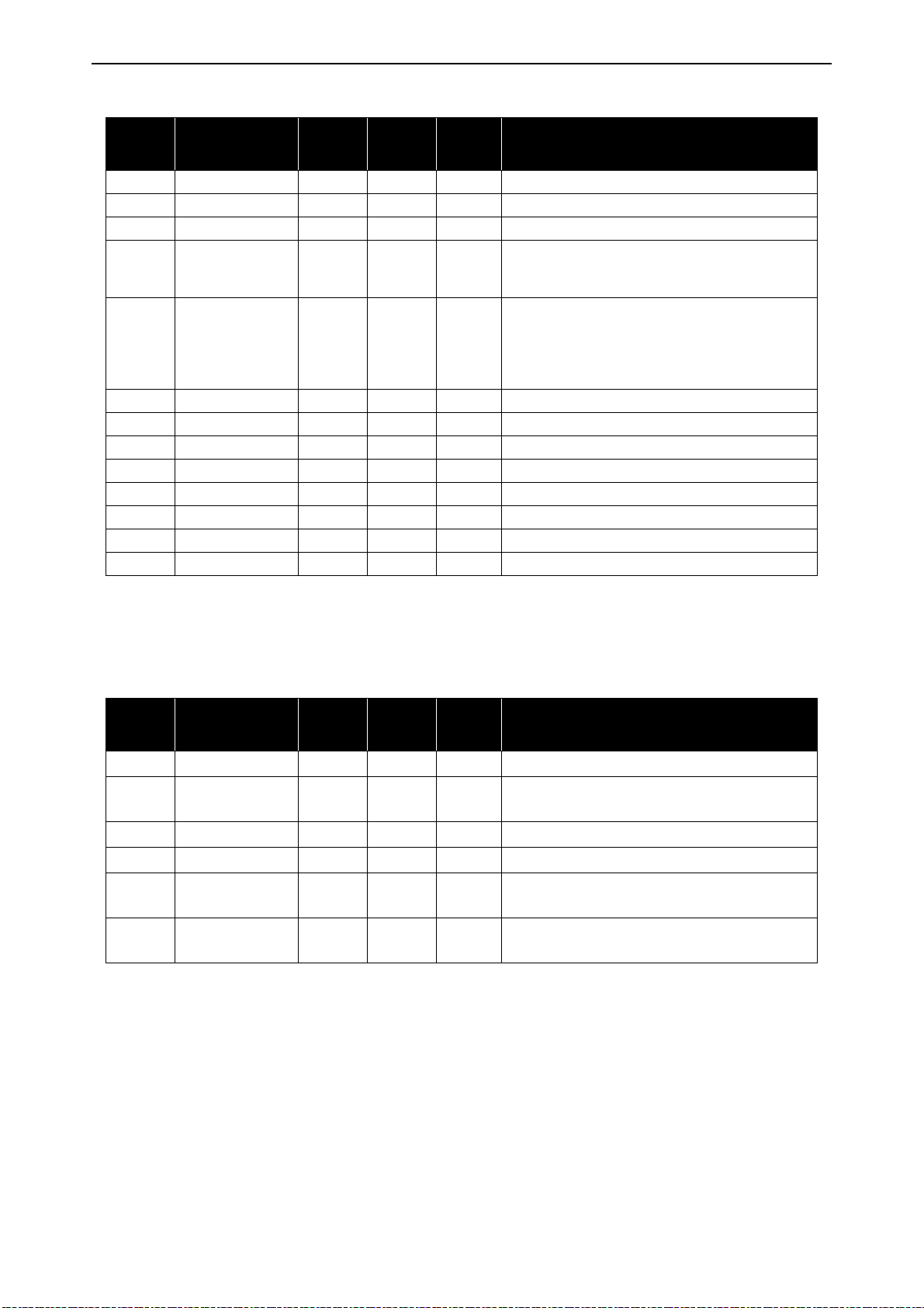
vacon • 82 Monitoring menu
Table 49. Fieldbus data monitoring
Code
V2.12.8 FB data in 6 1 881 Raw value of process data in 32-bit signed format
V2.12.9 FB data in 7 1 882 Raw value of process data in 32-bit signed format
V2.12.10 FB data in 8 1 883 Raw value of process data in 32-bit signed format
V2.12.11 FB Status Word 1 864
V2.12.12 FB Speed Actual 0.01 865
V2.12.13 FB data out 1 1 866 Raw value of process data in 32-bit signed format
V2.12.14 FB data out 2 1 867 Raw value of process data in 32-bit signed format
V2.12.15 FB data out 3 1 868 Raw value of process data in 32-bit signed format
V2.12.16 FB data out 4 1 869 Raw value of process data in 32-bit signed format
V2.12.17 FB data out 5 1 870 Raw value of process data in 32-bit signed format
V2.12.18 FB data out 6 1 871 Raw value of process data in 32-bit signed format
V2.12.19 FB data out 7 1 872 Raw value of process data in 32-bit signed format
V2.12.20 FB data out 8 1 873 Raw value of process data in 32-bit signed format
Monitoring
value
Unit Scale ID Description
Fieldbus status word sent by application in bypass
mode/format. Depending on the FB type or profile
the data can be modified before sent to the FB.
Actual speed in %. 0 and 100% correspond to minimum and maximum frequencies respectively.
This is continuously updated depending on the
momentary min and max frequencies and the output frequency.
6.1.11 Solar
Table 50. Solar monitoring items
Code
Monitoring
value
Unit Scale ID Description
V2.15.1 Vmp ref V 1914 DC voltage reference for MPP regulation
V2.15.2 Vmp ref correct V 1942
Present correction on DC voltage reference
(P&O + oscillation)
V2.15.3 Motor power kW 1938 Motor shaft power
V2.15.4 Energy counter MWh 1937 Counter of energy taken by the supply
B2.15.5
V2.15.6
Energy counter
reset
Irradiation
measure
W/m
1932 To reset V2.15.4
2
1982 Measurement from irradiation signal.
Local contacts: https://www.danfoss.com/en/contact-us/contacts-list/
Page 83

Monitoring menu vacon • 83
6.1.12 Flow
Table 51. Flow monitoring items
Code Monitoring value Unit
V2.16.1 Actual flow l/min 1956
V2.16.2 Volume counter 1*
V2.16.3 Volume counter 2*
B2.16.4
Volume counters
reset
m
104 x m
Scal
e
ID Description
Actual flow: it is measured by transducer define with P3.23.1
3
3
1955 Cumulative water volume counter.
1962 Cumulative water volume counter.
1961 To reset V2.16.2 and V2.16.3
NOTE!
* The total volume of water in [m3] is given by: V2.16.2 + (V2.16.3 x 10000).
Local contacts: https://www.danfoss.com/en/contact-us/contacts-list/
Page 84
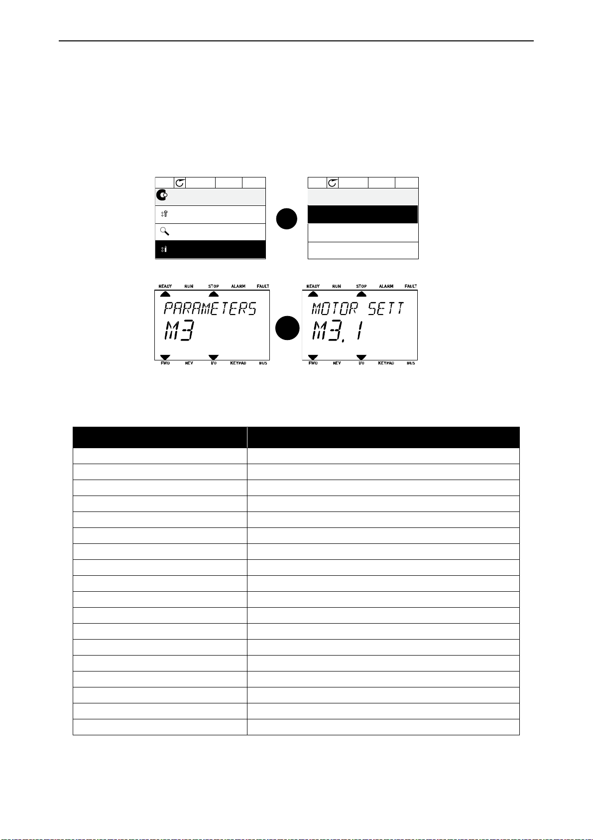
vacon • 84 Parameters
Main Menu
0
Quick Setup
( 17 )
0
( 6 )
Monitor
0
ID: M3
STOP READY Keypad
Parameters
( 13 )
0
STOP READY Keypad
0
0
0
0
Motor Settings
( 2 )
Start/Stop Setup
( 7 )
References
( 18 )
Parameters
ID: M3.1
OK
9147.emf
OK
9151.emf
7. P
ARAMETERS
The VACON® AC drive contains a preloaded VACON® 100X Solar Pump application for instant use.
The parameters of this application are listed in this chapter.
7.1 Application parameter lists
Find the parameter menu and the parameter groups as guided below.
The VACON® 100 X Solar Pump Application embodies the following parameter groups:
Table 52. Parameter groups
Menu and Parameter group Description
Group 3.1: Motor settings Basic and advanced motor settings
Group 3.2: Start/Stop setup Start and stop functions
Group 3.3: References Parameters for setting references and preset speeds.
Group 3.4: Ramps And Brakes Acceleration/Deceleration setup
Group 3.5: I/O Config I/O programming
Group 3.6: Fieldbus DataMap Process data in/out mapping
Group 3.7: Prohibit Freq Prohibit frequencies programming
Group 3.8: Supervisions Programmable limit controllers
Group 3.9: Protections Protections configuration
Group 3.10: Automatic reset Auto reset after fault configuration
Group 3.11: Appl. Settings Application settings
Group 3.12: Timer functions Configuration of 3 timers based on Real Time Clock.
Group 3.13: PID Controller Parameters for PID Controller 1.
Group 3.14: ExtPID Controller Parameters for external PID Controller.
Group 3.16: Mainten. Counters Parameters related to Maintenance counters.
Group 3.21: Pump Control Pump function parameters
Group 3.22: Solar Solar specific function parameters
Group 3.23: Flow meter Flow meter parameters
Local contacts: https://www.danfoss.com/en/contact-us/contacts-list/
Page 85
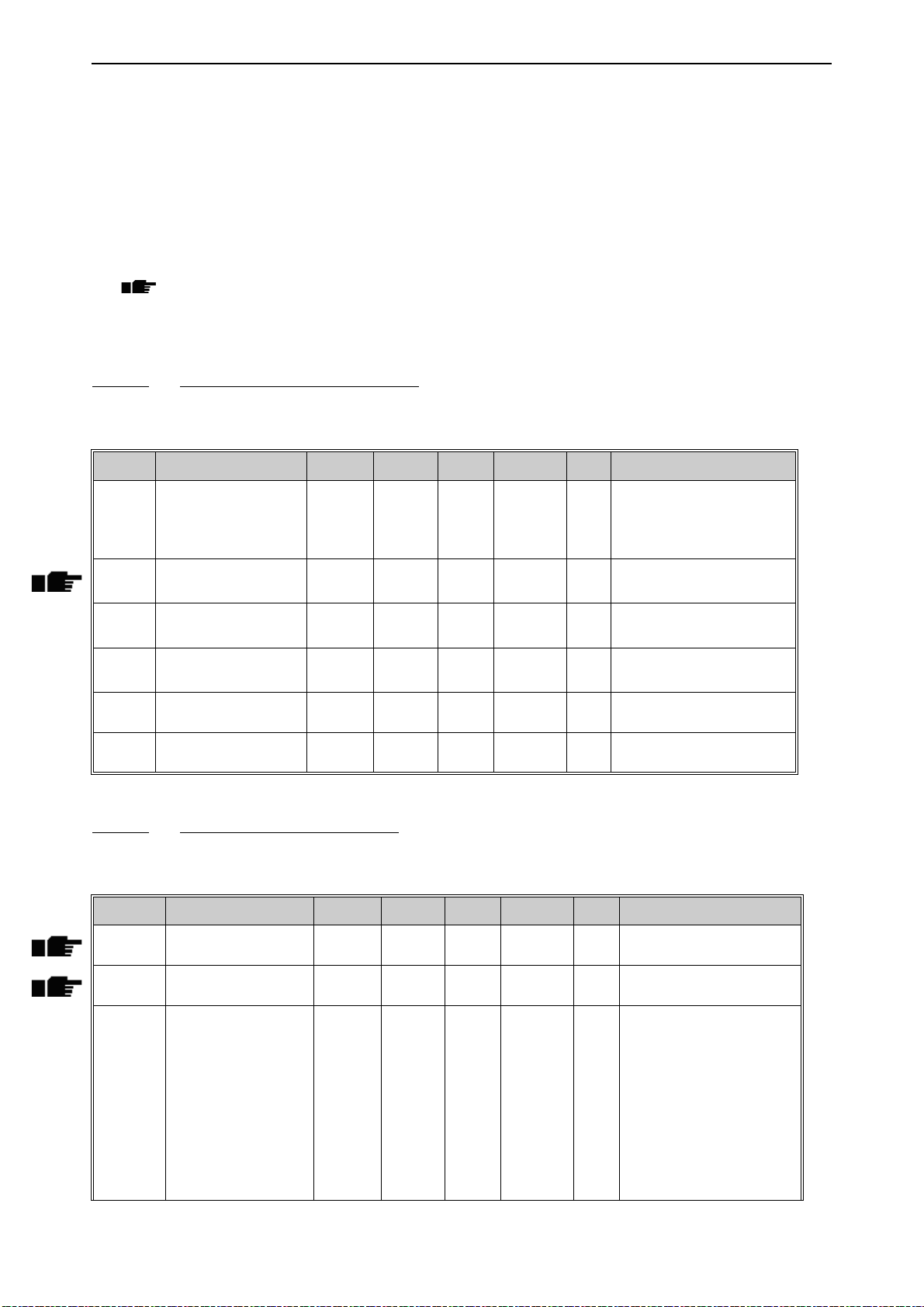
Parameters vacon • 85
7.1.1 Column explanations
Code = Location indication on the keypad; Shows the operator the parameter number.
Parameter= Name of parameter
Min = Minimum value of parameter
Max = Maximum value of parameter
Unit = Unit of parameter value; Given if available
Default = Value preset by factory
ID = ID number of the parameter
Description= Short description of parameter values or its function
= More information on this parameter available; Click the parameter name
7.1.2 Group 3.1: Motor settings
7.1.2.1 Group 3.1.1: Motor nameplate
Table 53. Motor nameplate parameters
Code Parameter Min Max Unit Default ID Description
Find this value Un on the
P3.1.1.1 Motor Nom Voltg Varies Varies V Varies 110
P3.1.1.2 Motor Nom Freq 8.00 320.00 Hz Varies 111
P3.1.1.3 Motor Nom Speed 24 19200 rpm Varies 112
P3.1.1.4 Motor Nom Currnt Varies Varies A Varies 113
P3.1.1.5 Motor Cos Phi 0.30 1.00 0.74 120
P3.1.1.6 Motor Nom Power Varies Varies kW Varies 116
rating plate of the motor.
Note also used connection
(Delta/Star).
Find this value fn on the rating plate of the motor.
Find this value nn on the rating plate of the motor.
Find this value In on the rating plate of the motor.
Find this value on the rating
plate of the motor
Find this value In on the rating plate of the motor.
7.1.2.2 Group 3.1.2: Motor Control
Table 54. Motor control
Code Parameter Min Max Unit Default ID Description
P3.1.2.1 Control mode 0 1 0 600
P3.1.2.2 Motor type 0 1 0 650
P3.1.2.3 Switching Freq 1.5 Varies kHz Varies 601
Local contacts: https://www.danfoss.com/en/contact-us/contacts-list/
0 = U/f Freq ctrl open loop
1 = Speed control open loop
0 = Induction motor
1 = PM motor
Increasing the switching
frequency reduces the
capacity of the AC drive. It is
recommended to use a
lower frequency when the
motor cable is long in order
to minimize capacitive currents in the cable. Motor
noise can also be minimised
using a high switching frequency.
Page 86

vacon • 86 Parameters
Table 54. Motor control
Code Parameter Min Max Unit Default ID Description
The automatic motor identification calculates or measures the motor parameters
P3.1.2.4 Identification 0 1 0 631
P3.1.2.5 Magnetizing current 0.0 2*IH A 0.0 612
P3.1.2.6 Motor switch 0 1 0 653
P3.1.2.7 Load drooping 0.00 50.00 % 0.00 620
P3.1.2.8 Load drooping time 0.00 2.00 s 0.00 656
P3.1.2.9 Load drooping mode 0 1 0 1534
P3.1.2.11 Under Volt. Control 0 1 1 608
P3.1.2.12 Energy optimization 0 1 0 666
P3.1.2.13 StatorVoltAdjust 50.0 150.0 % 100.0 659
that are needed for optimum motor and speed control.
0 = No action
1 = At standstill
Motor magnetizing current
(no-load current). The values of the U/f parameters
are identified by the magnetizing current if given before
the identification run. If this
value is set to zero, magnetizing current will be internally calculated.
Enabling this function prevents the drive from tripping
when the motor switch is
closed and opened e.g.
using flying start.
0 = Disabled
1 = Enabled
The drooping function
enables speed drop as a
function of load. Drooping
will be defined in percent of
nominal speed at nominal
load.
Load drooping is used in
order to achieve a dynamic
speed drooping because of
changing load. This parameter defines the time during
which the speed is restored
to the level it was before the
load increase.
0 = Normal; Load drooping
factor is constant through
the whole frequency range
1 = Linear removal; Load
drooping is removed linearly
from nominal frequency to
zero frequency
0 = Disabled
1 = Enabled
The drive searches for the
minimum motor current in
order to save energy and to
lower the motor noise. This
function can be used e.g. in
fan and pump applications
0 = Disabled
1 = Enabled
Parameter for adjusting the
stator voltage in permanent
magnet motors.
Local contacts: https://www.danfoss.com/en/contact-us/contacts-list/
Page 87
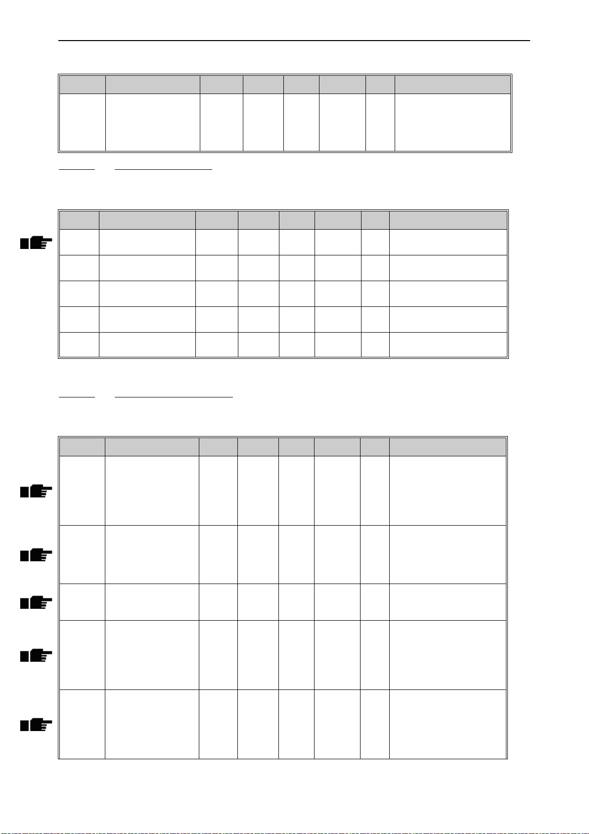
Parameters vacon • 87
Table 54. Motor control
Code Parameter Min Max Unit Default ID Description
Maximizes drive output voltage, but increases motor
P3.1.2.14 Overmodulation 0 1 1
current harmonics.
0= Disabled
1= Enabled
7.1.2.3 Group 3.1.3: Limits
Table 55. Motor limit settings
Code Parameter Min Max Unit Default ID Description
P3.1.3.1 Current limit Varies Varies A Varies 107
P3.1.3.2 MotorTorqueLimit 0.0 300.0 % 300.0 1287
P3.1.3.3 GenerTorqueLimit 0.0 300.0 % 300.0 1288
P3.1.3.4 MotorPowerLimit 0.0 300.0 % 300.0 1290
P3.1.3.5 GenerPowerLimit 0.0 300.0 % 300.0 1289
Maximum motor current
from AC drive
Maximum motoring side
torque limit
Maximum generating side
torque limit
Maximum motoring side
power limit
Maximum generating side
power limit
7.1.2.4 Group 3.1.4: Open loop
Table 56. Open loop settings
Code Parameter Min Max Unit Default ID Description
Type of U/f curve between
zero frequency and the field
P3.1.4.1 U/f ratio 0 2 0 108
P3.1.4.2 Field WeakngPnt 8.00 P3.3.1.2 Hz Varies 602
P3.1.4.3 Voltage at FWP 10.00 200.00 % 100.00 603
P3.1.4.4 U/f Mid Freq 0.00 P3.1.4.2 Hz Varies 604
P3.1.4.5 U/f Mid Voltg 0.0 100.0 % 100.0 605
weakening point.
0=Linear
1=Squared
2=Programmable
The field weakening point is
the output frequency at
which the output voltage
reaches the field weakening
point voltage
Voltage at field weakening
point in % of motor nominal
voltage
Provided that the programmable U/f curve has been
selected (par. P3.1.4.1), this
parameter defines the middle point frequency of the
curve.
Provided that the programmable U/f curve has been
selected (par. P3.1.4.1), this
parameter defines the middle point voltage of the
curve.
Local contacts: https://www.danfoss.com/en/contact-us/contacts-list/
Page 88

vacon • 88 Parameters
Table 56. Open loop settings
Code Parameter Min Max Unit Default ID Description
This parameter defines the
zero frequency voltage of
P3.1.4.6 Zero Freq Voltg 0.00 40.00 % Varies 606
P3.1.4.7 Flying Start Options 0 1 0 1590
P3.1.4.8 FlyStartScanCurrent 0.0 100.0 % 45.0 1610
P3.1.4.9 Auto TorqueBoost 0 1 0 109
P3.1.4.10
P3.1.4.11
Torque boost motor
gain
Torque boost genera-
tor gain
0.0 100.0 % 100.0 667
0.0 100.0 % 0.0 665
the U/f curve. The default
value varies according to
unit size.
Checkbox selection:
B0 = Search shaft frequency
from same direction as frequency reference.
B1 = Disable AC scanning
B4 = Use frequency reference for initial guess
B5 = Disable DC pulses
Defined in percentage of
motor nominal current.
Automatic torque boost can
be used in application where
starting torque due to starting friction is high.
0= Disabled
1= Enabled
Scaling factor for motoring
side IR-compensation when
torque boost is used.
Scaling factor for generating
side IR-compensation when
torque boost is used.
7.1.2.5 Group 3.1.4.12: I/f start
The
I/f Start
function is typically used with permanent magnet synchronous motors (PMSM) to start
the motor with constant current control. This is useful with high power motors in which the resistance is low and the tuning of the U/f curve difficult.
The
I/f Start
function can be used with induction motors (IM), too, e.g. if the tuning of the U/f curve
is difficult at low frequencies.
Applying the I/f Start function may also prove useful in providing sufficient torque for the motor at
startup.
Local contacts: https://www.danfoss.com/en/contact-us/contacts-list/
Page 89
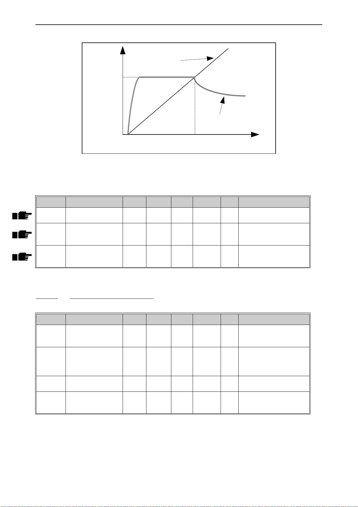
Parameters vacon • 89
Motor Current
Time
[s]
I/
f Start
Frequency
I/
f Start Current
Output Frequency
9240.emf
Figure 30. I/f start
Table 57. I/f start parameters
Code Parameter Min Max Unit Default ID Description
P3.1.4.12.1 I/f start 0 1 0 534
P3.1.4.12.2 I/f start frequency 0.0
P3.1.1
.2
% 15.0 535
0 = Disabled
1 = Enabled
Output frequency limit
below which the defined I/f
start current is fed to motor.
The current fed to the motor
P3.1.4.12.3 I/f start current 0.0 100.0 % 80.0 536
when the I/f start function is
activated.
7.1.2.6 Group 3.1.4.13: Stabilators
Code Parameter Min Max Unit Default ID Description
Gain of the torque stabilator
P3.1.4.13.1 TorqStabGain 0.0 500.0 % 50.0 1412
P3.1.4.13.2 TorqStabGainFWP 0.0 500.0 % 50.0 1414
P3.1.4.13.3 TorqStabDampTC 0.0005 1.0000 s 0.0050 1413
P3.1.4.13.4
TorqStabDampTC
PMM
0.0005 1.0000 s 0.0500 1735
in open loop motor control
operation.
Gain of the torque stabilator
at field weakening point in
open loop motor control
operation.
Damping time of torque stabilizer
Damping time constant of
torque stabilizer for PMmotor.
Local contacts: https://www.danfoss.com/en/contact-us/contacts-list/
Page 90

vacon • 90 Parameters
7.1.3 Group 3.2: Start/Stop setup
Start/Stop commands are given differently depending on the control place.
Remote control place (I/O A): Start, stop and reverse commands are controlled by 2 digital inputs
chosen with parameters P3.5.1.1 and P3.5.1.2. The functionality/logic for these inputs is then selected with parameter P3.2.6 (in this group).
Remote control place (I/O B): Start, stop and reverse commands are controlled by 2 digital inputs
chosen with parameters P3.5.1.4 and P3.5.1.5. The functionality/logic for these inputs is then selected with parameter P3.2.7 (in this group).
Local control place (Keypad): Start and stop commands come from the keypad buttons, while the
direction of rotation is selected by the parameter P3.3.1.9.
Remote control place (Fieldbus): Start, stop and reverse commands come from fieldbus.
Table 58. Start/Stop Setup menu
Code Parameter Min Max Unit Default ID Description
Selection of remote control
place (start/stop). Can be
used to change back to
P3.2.1 Rem.Ctrl. Place 0 1 0 172
P3.2.2 Local/Remote 0 1 0 211
P3.2.3 Keypad stop button 0 1 0 114
P3.2.4 Start function 0 1 0 505
P3.2.5 Stop function 0 2 0 506
P3.2.6 I/O A logic 0 4 1 300
P3.2.7 I/O B logic 0 4 1 363 See above.
P3.2.8 FB Start logic 0 1 0 889
remote control from
VACON® Live e.g. in case
of a broken panel.
0=I/O control
1=Fieldbus control
Switch between local and
remote control places
0=Remote
1=Local
0=Stop button always
enabled (Yes)
1=Limited function of Stop
button (No)
0=Ramping
1=Flying start
0: coasting
1: ramp to min frequency
2: ramp to zero frequency
Logic = 0:
Start sign 1 = Start Forward
Start sign 2 = Start Backward
Logic =1:
Start sign 1 = Start
Start sign 2 = Reverse
Logic = 2:
Double Start
Logic = 3:
Start sign 1 + Analogue sign
Logic = 4:
Solar only
0=Rising edge required
1=State
Local contacts: https://www.danfoss.com/en/contact-us/contacts-list/
Page 91

Parameters vacon • 91
Table 58. Start/Stop Setup menu
Code Parameter Min Max Unit Default ID Description
Choose whether to copy the
Run state and Reference
when changing from
P3.2.10 Rem to Loc Funct 0 2 2 181
P3.2.11 Start Analogue Signal 0 1 0 1810
P3.2.12 Start Analogue Level 0.00 100.00 % 10.00 1857
P3.2.13 Stop Analogue Level 0.00 100.00 % 80.00 1856
Remote to Local (keypad)
control:
0 = Keep Run
1 = Keep Run & Reference
2 = Stop
0= AI1
1= AI2
Start is set below this level
(unscaled signal). Startstop logic is reversed if >
P3.2.13
Start is set above this level
(unscaled signal). Startstop logic is reversed if <
P3.2.12
Local contacts: https://www.danfoss.com/en/contact-us/contacts-list/
Page 92

vacon • 92 Parameters
7.1.4 Group 3.3: References
7.1.4.1 Frequency reference
The frequency reference source is programmable for all control places except PC, which always
takes the reference from the PC tool.
Remote control place (I/O A): The source of frequency reference can be selected with parameter
P3.3.1.5.
Remote control place (I/O B): The source of frequency reference can be selected with parameter
P3.3.1.6.
Local control place (Keypad): If the default selection for parameter P3.3.1.7 is used the reference
set with parameter P3.3.1.8 applies.
Remote control place (Fieldbus): The frequency reference comes from fieldbus if the default value
for parameter P3.3.1.11 is kept.
Table 59. Frequency reference parameters
Code Parameter Min Max Unit Default ID Description
P3.3.1.1 MinFreqReference 0.00 P3.3.1.2 Hz 0.00 101
P3.3.1.2 MaxFreqReference P3.3.1.1 320.00 Hz 50.00 102
P3.3.1.3 PosFreqRefLimit -320.0 320.0 Hz 320.00 1285
P3.3.1.4 NegFreqRefLimit -320.0 320.0 Hz -320.00 1286
P3.3.1.5 I/O A Ref sel 1 9 5 117
P3.3.1.6 I/O B Ref sel 1 9 9 131
P3.3.1.7 Keypad Ref Sel 1 9 2 121
Minimum allowed frequency
reference
Maximum allowed frequency
reference
Final frequency reference
limit for positive direction.
Final frequency reference
limit for negative direction.
NOTE:
be used e.g. to prevent motor
from running in reverse
direction.
Selection of ref source when
control place is I/O A
1 = Preset Frequency 0
2 = Keypad reference
3 = Fieldbus
4 = AI1
5 = AI2
6 = AI1+AI2
7 = PID reference
8 = Motor potentiometer
9 = Max Power
Selection of ref source when
control place is I/O B. See
above.
NOTE: I/O B control place can
only be forced active with digital input (P3.5.1.7).
Selection of ref source when
control place is keypad:
1 = Preset Frequency 0
2 = Keypad reference
3 = Fieldbus
4 = AI1
5 = AI2
6 = AI1+AI2
7 = PID reference
8 = Motor potentiometer
9 = Max Power
This parameter can
Local contacts: https://www.danfoss.com/en/contact-us/contacts-list/
Page 93

Parameters vacon • 93
Table 59. Frequency reference parameters
Code Parameter Min Max Unit Default ID Description
The frequency reference can
P3.3.1.8 Keypad Reference 0.00 P3.3.1.2 Hz 0.00 184
P3.3.1.9 Keypad Direction 0 1 0 123
P3.3.1.10 Fieldbus Ref Sel 1 9 3 122
P3.3.1.11 Adapt To AC Volt. No Yes No 1931
be adjusted on the keypad
with this parameter.
Motor rotation when control
place is keypad
0 = Forward
1 = Reverse
Selection of ref source when
control place is Fieldbus:
1 = Preset Frequency 0
2 = Keypad reference
3 = Fieldbus
4 = AI1
5 = AI2
6 = AI1+AI2
7 = PID reference
8 = Motor potentiometer
9 = Max Power
Parameter enables the possible limitation on maximum
output frequency when connected to AC mains (digital
input from P3.5.1.53 is active),
in case the available voltage
is not sufficient to reach the
motor nominal U/f ratio (from
P3.1.1.1 and P3.1.1.2).
The function can be useful if
the motor has been chosen
depending on high DC voltage
from solar modules, but this
voltage is not reachable with
AC supply.
Local contacts: https://www.danfoss.com/en/contact-us/contacts-list/
Page 94

vacon • 94 Parameters
7.1.4.2 Group 3.3.3: Preset Freqs
Table 60. Preset frequencies parameters
Code Parameter Min Max Unit Default ID Description
0 = Binary coded
1 = Number of inputs. Preset
P3.3.3.1 PresetFreqMode 0 1 0 182
P3.3.3.2 Preset Freq 0 P3.3.1.1 P3.3.1.2 Hz 5.00 180
P3.3.3.3 Preset Freq 1 P3.3.1.1 P3.3.1.2 Hz 10.00 105
P3.3.3.4 Preset Freq 2 P3.3.1.1 P3.3.1.2 Hz 15.00 106
P3.3.3.5 Preset Freq 3 P3.3.1.1 P3.3.1.2 Hz 20.00 126
P3.3.3.6 Preset Freq 4 P3.3.1.1 P3.3.1.2 Hz 25.00 127
P3.3.3.7 Preset Freq 5 P3.3.1.1 P3.3.1.2 Hz 30.00 128
P3.3.3.8 Preset Freq 6 P3.3.1.1 P3.3.1.2 Hz 40.00 129
P3.3.3.9 Preset Freq 7 P3.3.1.1 P3.3.1.2 Hz 50.00 130
P3.3.3.10 Preset Freq Sel0
P3.3.3.11 Preset Freq Sel1
P3.3.3.12 Preset Freq Sel2
DigIN
SlotA.4
DigIN
SlotA.5
DigIN
Slot0.1
frequency is selected according
to how many of preset speed
digital inputs are active
Basic preset frequency 0 when
selected by Control reference
parameter (P3.3.1.5).
Select with digital input:
Preset frequency selection 0
(P3.3.3.10)
Select with digital input:
Preset frequency selection 1
(P3.3.3.11)
Select with digital inputs: Preset
frequency selection 0 & 1
Select with digital input:
Preset frequency selection 2
(P3.3.3.12)
Select with digital inputs: Preset
frequency selection 0 & 2
Select with digital inputs: Preset
frequency selection 1 & 2
Select with digital inputs: Preset
frequency selection 0 & 1 & 2
Binary selector for Preset
419
speeds (0-7). See parameters
P3.3.3.2 to P3.3.3.9.
Binary selector for Preset
420
speeds (0-7). See parameters
P3.3.3.2 to P3.3.3.9.
Binary selector for Preset
421
speeds (0-7). See parameters
P3.3.3.2 to P3.3.3.9.
Local contacts: https://www.danfoss.com/en/contact-us/contacts-list/
Page 95

Parameters vacon • 95
7.1.4.3 Group 3.3.4: Motor Potentiom
With a motor potentiometer function, the user can increase and decrease the output frequency. By
connecting a digital input to parameter P3.3.4.1 (
tive, the output frequency will rise as long as the signal is active. The parameter P3.3.4.2 (
DOWN
) works vice versa, decreasing the output frequency.
MotPot UP
) and having the digital input signal ac-
MotPot
The rate how the output frequency either rises or falls when Motor Potentiometer Up or Down is
activated is determined by the
Motor potentiometer ramp time
(P3.3.4.3)
The Motor potentiometer reset parameter (P3.3.4.4) is used to choose whether to reset (set to MinFreq) the Motor Potentiometer frequency reference when stopped or when powered down.
Motor potentiometer frequency reference is available in all control places in menu Group 3.3: References. The motor potentiometer reference can be changed only when the drive is in run state.
Table 61. Motor potentiometer parameters
Code Parameter Min Max Unit Default ID Description
FALSE = Not active
P3.3.4.1 MotPot UP
P3.3.4.2 MotPot DOWN
P3.3.4.3 MotPot Ramp Time 0.1 500.0 Hz/s 10.0 331
P3.3.4.4 MotPot Reset 0 2 1 367
DigIN
Slot0.1
DigIN
Slot0.1
TRUE = Active (Motor poten-
418
tiometer reference
INCREASES until the contact
is opened)
FALSE = Not active
TRUE = Active (Motor poten-
417
tiometer reference
DECREASES until the contact
is opened)
Rate of change in the motor
potentiometer reference
when increased or decreased
with parameters P3.3.4.1 or
P3.3.4.2.
Motor potentiometer frequency reference reset logic.
0 = No reset
1 = Reset if stopped
2 = Reset if powered down
Local contacts: https://www.danfoss.com/en/contact-us/contacts-list/
Page 96
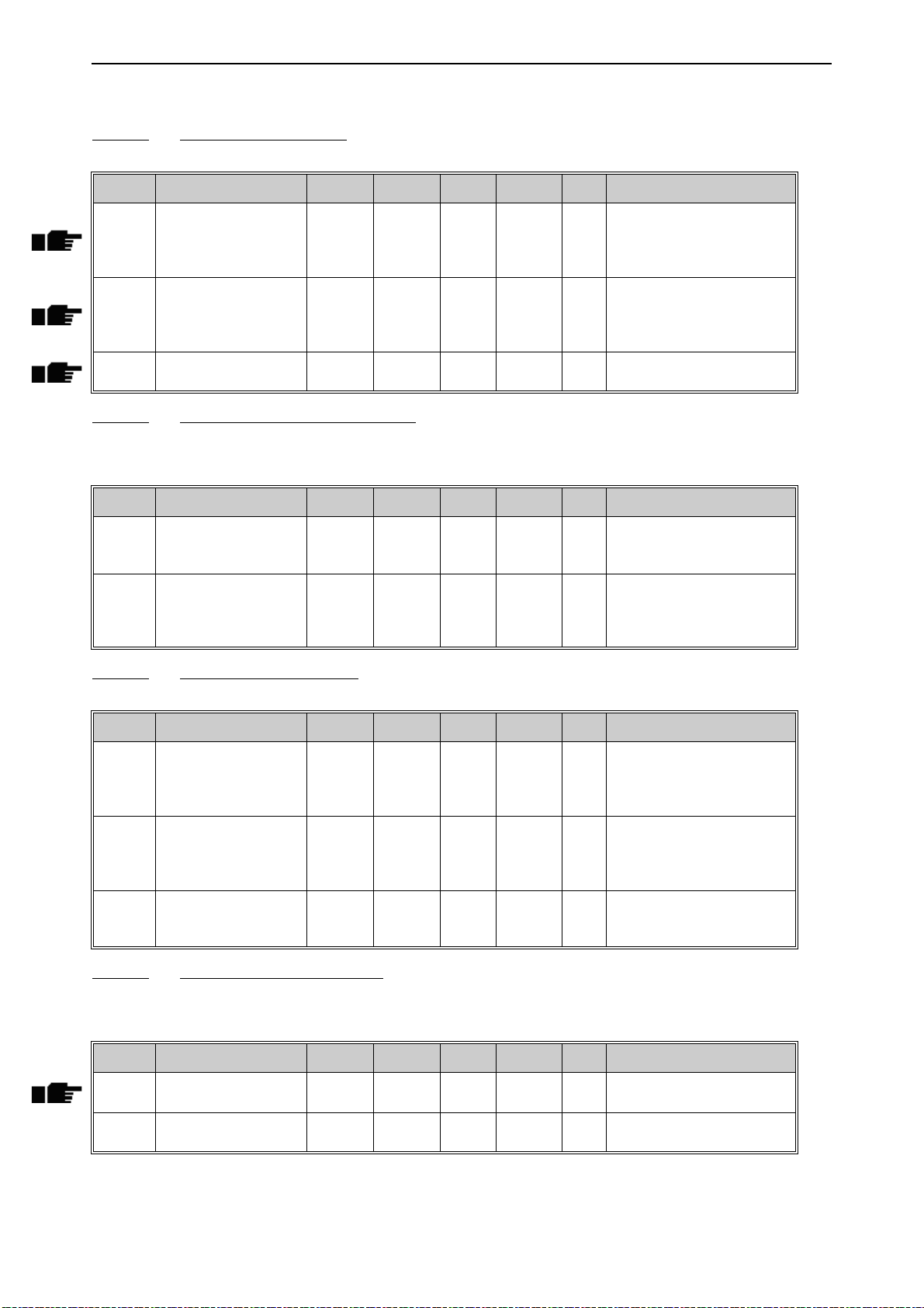
vacon • 96 Parameters
7.1.5 Group 3.4: Ramps And Brakes
7.1.5.1 Group 3.4.1: Ramp 1
Table 62. Ramp 1 setup
Code Parameter Min Max Unit Default ID Description
Defines the time required for
P3.4.1.2 Accel Time 1 0.1 3000.0 s 5.0 103
P3.4.1.3 Decel Time 1 0.1 3000.0 s 5.0 104
P3.4.1.4
Start Acceleration
Time
0.1 3000.0 s 2.0 502 Time from 0 to min frequency
7.1.5.2 Group 3.4.3: Start Magnetizat
Table 63. Start magnetization parameters
Code Parameter Min Max Unit Default ID Description
the output frequency to
increase from zero frequency
to maximum frequency
Defines the time required for
the output frequency to
decrease from maximum frequency to zero frequency
Defines the DC current fed
P3.4.3.1 StartMagnCurrent 0.00 Varies A Varies 517
P3.4.3.2 StartMagnTime 0,00 600,00 s 0,00 516
into motor at start. Disabled
if set to 0.
This parameter defines the
time for how long DC current
is fed to motor before acceleration starts.
7.1.5.3 Group 3.4.3: DC brake
Table 64. DC-brake parameters
Code Parameter Min Max Unit Default ID Description
Defines the current injected
P3.4.4.1 DC Brake Current Varies Varies A Varies 507
P3.4.4.2 DC BrakeTime 0,00 600,00 s 0,00 508
P3.4.4.3 DC Start Freq 0,10 10,00 Hz 1,50 515
into the motor during DCbraking.
0 = Disabled
Determines if braking is ON
or OFF and the braking time
of the DC-brake when the
motor is stopping.
The output frequency at
which the DC-braking is
applied.
7.1.5.4 Group 3.4.5: Flux Braking
Table 65. Flux braking parameters
Code Parameter Min Max Unit Default ID Description
P3.4.5.1 Flux Braking 0 1 0 520
P3.4.5.2 Braking Current 0 Varies A Varies 519
Local contacts: https://www.danfoss.com/en/contact-us/contacts-list/
0=Disabled
1=Enabled
Defines the current level for
flux braking.
Page 97
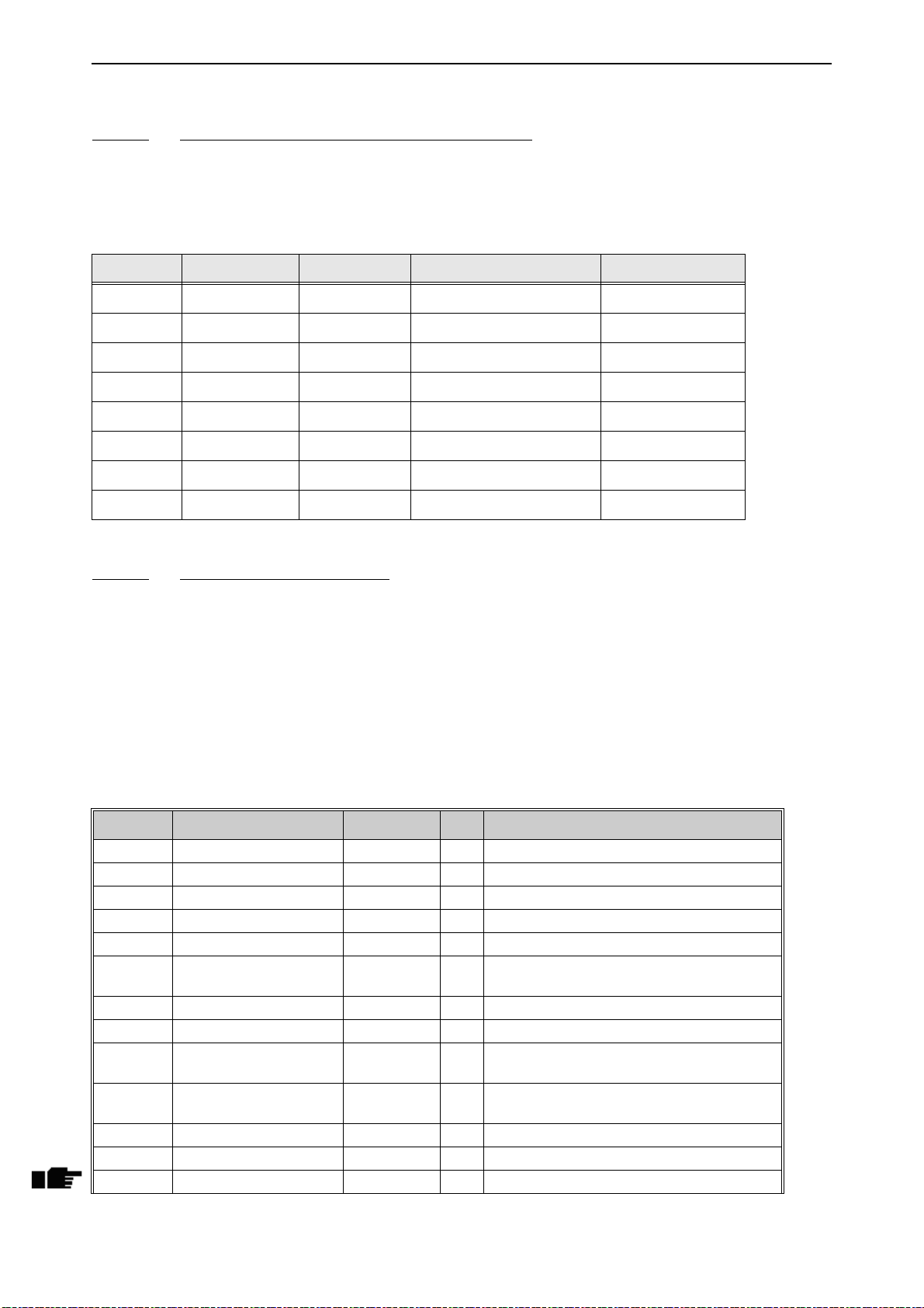
Parameters vacon • 97
7.1.6 Group 3.5: I/O Config
7.1.6.1 Default assignments of programmable inputs
Table 66 below presents the default assignments of programmable digital and analogue inputs in
VACON® 100 X Solar Pump application.
Table 66. Default assignments of inputs
Input Terminal(s) Reference Assigned function Parameter code
DI1 8 A.1 Ctrl signal 1 A P3.5.1.1
DI2 9 A.2 Ctrl signal 2 A P3.5.1.2
DI3 10 A.3 External fault close P3.5.1.11
DI4 14 A.4 Preset frequency selection 0 P3.5.1.21
DI5 15 A.5 Preset frequency selection 1 P3.5.1.22
DI6 16 A.6 External fault close P3.5.1.13
AI1 2/3 A.1 AI1 signal selection P3.5.2.1.1
AI2 4/5 A.2 AI2 signal selection P3.5.2.2.1
7.1.6.2 Group 3.5.1: Digital inputs
Digital inputs are very flexible to use. Parameters are functions that are connected to the required
digital input terminal (see chapter 5). The digital inputs are represented as, for example,
A.2,
meaning the second input on slot A.
DigIN Slot
It is also possible to connect the digital inputs to time channels which are also represented as terminals.
NOTE! The statuses of digital inputs and the digital output can be monitored in the Multimonitoring
view.
Table 67. Digital input settings
Code Parameter Default ID Description
P3.5.1.1 Ctrl signal 1 A DigIN SlotA.1 403 Ctrl signal 1 when control place is I/O A (FWD)
P3.5.1.2 Ctrl signal 2 A DigIN SlotA.2 404 Ctrl signal 2 when control place is I/O A (REV)
P3.5.1.4 Ctrl signal 1 B DigIN Slot0.1 423 Start signal 1 when control place is I/O B
P3.5.1.5 Ctrl signal 2 B DigIN Slot0.1 424 Start signal 2 when control place is I/O B
P3.5.1.7 I/O B Ctrl Force DigIN Slot0.1 425 TRUE = Force the control place to I/O B
P3.5.1.8 I/O B Ref Force DigIN Slot0.1 343
P3.5.1.9 Fieldbus Ctrl Force DigIN Slot0.1 411 Force control to fieldbus
P3.5.1.10 Keypad Ctrl Force DigIN Slot0.1 410 Force control to keypad
P3.5.1.11 Ext Fault Close DigIN SlotA.3 405
P3.5.1.12 Ext Fault Open DigIN Slot0.2 406
P3.5.1.13 Fault Reset Close DigIN SlotA.6 414 Resets all active faults when TRUE
P3.5.1.14 Fault Reset Open DigIN Slot0.1 213 Resets all active faults when FALSE
P3.5.1.15 Run Enable DigIN Slot0.2 407 Must be on to set drive in Ready state
TRUE = Used frequency reference is specified
by I/O reference B parameter (P3.3.1.6).
FALSE = OK
TRUE = External fault
FALSE = External fault
TRUE = OK
Local contacts: https://www.danfoss.com/en/contact-us/contacts-list/
Page 98
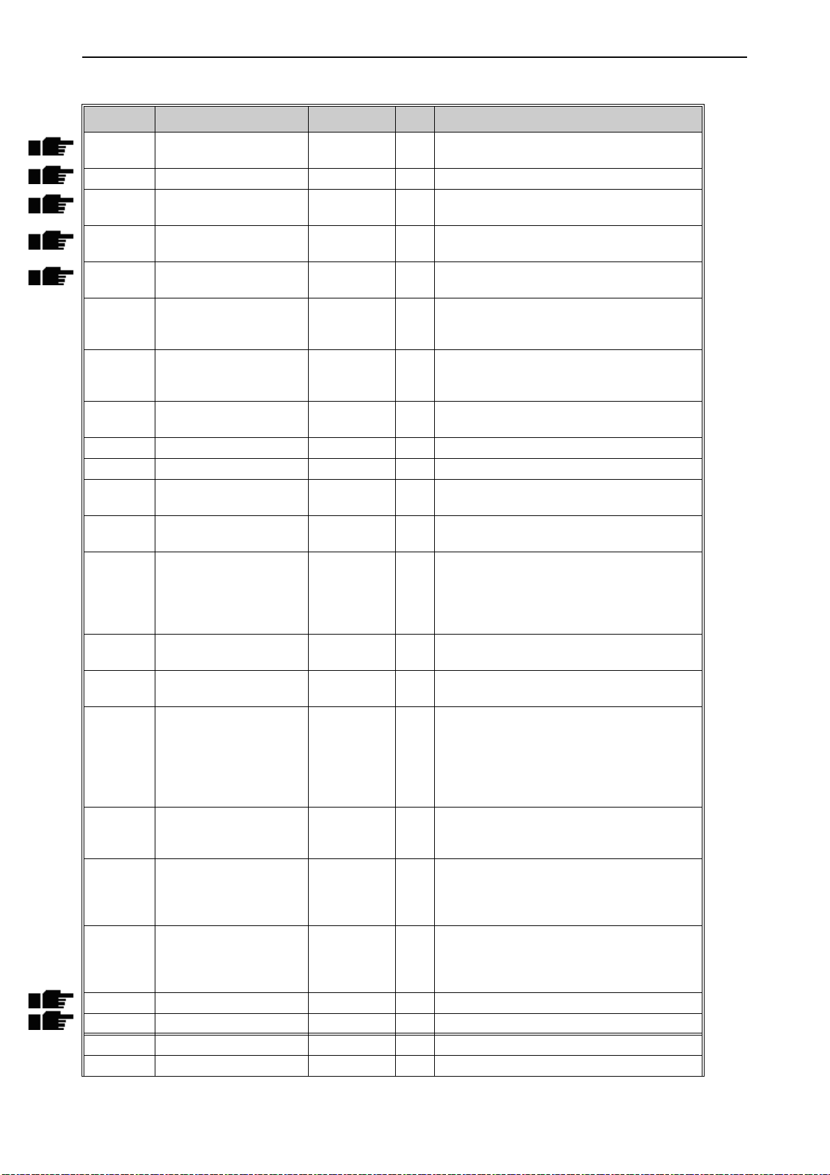
vacon • 98 Parameters
Table 67. Digital input settings
Code Parameter Default ID Description
P3.5.1.16 Run Interlock 1 DigIN Slot0.2 1041
P3.5.1.17 Run Interlock 2 DigIN Slot0.2 1042 As above.
P3.5.1.21 Preset Freq Sel0 DigIN SlotA.4 419
P3.5.1.22 Preset Freq Sel1 DigIN SlotA.5 420
P3.5.1.23 Preset Freq Sel2 DigIN Slot0.1 421
P3.5.1.24 MotPot UP DigIN Slot0.1 418
P3.5.1.25 MotPot DOWN DigIN Slot0.1 417
P3.5.1.27 Timer 1 DigIN Slot0.1 447
P3.5.1.28 Timer 2 DigIN Slot0.1 448 See above
P3.5.1.29 Timer 3 DigIN Slot0.1 449 See above
P3.5.1.30 PID SP Boost DigIN Slot0.1 1046
P3.5.1.31 PID SP Selection DigIN Slot0.1 1047
P3.5.1.32 ExtPID StartSignal DigIN Slot0.2 1049
P3.5.1.33 ExtPID SP Select DigIN Slot0.1 1048
P3.5.1.40 MainCounter1Reset DigIN Slot0.1 490
P3.5.1.48 AutoClean Activ. DigIN Slot0.1 1715
P3.5.1.49 Param. Set 1/2 Sel. DigIN Slot0.1 496
P3.5.1.50 User Defined Fault 1 DigIN Slot0.1
P3.5.1.51 User Defined Fault 2 DigIN Slot0.1
P3.5.1.52 Energy Counter reset DigIN Slot0.1 1933 Energy Counter reset
P3.5.1.53 Mains supply on DigIN Slot0.1 1934 Mains supply on
P3.5.1.54 Flowmeter pulse DigIN Slot0.1 1953 Digital input for pulse flow meter (P3.23.1 = 1)
P3.5.1.55 Volume counters reset DigIN Slot0.1 1957 Digital input for Volume counters reset
Drive may be ready but start is blocked as long
as interlock is on (Damper interlock).
Binary selector for Preset speeds (0-7). See
page 94.
Binary selector for Preset speeds (0-7). See
page 94.
Binary selector for Preset speeds (0-7). See
page 94.
FALSE = Not active
TRUE = Active (Motor potentiometer reference
INCREASES until the contact is opened)
FALSE = Not active
TRUE = Active (Motor potentiometer reference
DECREASES until the contact is opened)
Rising edge starts Timer 1 programmed in
Group 3.12: Timer functions parameter group
FALSE = No boost
TRUE = Boost
FALSE = Setpoint 1
TRUE = Setpoint 2
FALSE = PID2 in stop mode
TRUE = PID2 regulating
This parameter will have no effect if the external PID-controller is not enabled in Group 3.14:
ExtPID Controller.
FALSE = Setpoint 1
TRUE = Setpoint 2
Reset the counter from digital input.
TRUE = Reset
Start the Auto-cleaning sequence.
The sequence will be aborted if activation signal is removed before the sequence has been
completed.
NOTE!
vated!
Parameter set 1/2 selection.
Open= Parameter Set 1
Closed= Parameter Set 2
Digital input selection for activating User
1552
Defined Fault (1 or 2).
3
Open= No operation
Closed= Fault Activated
Digital input selection for activating User
1552
Defined Fault (1 or 2).
4
Open= No operation
Closed= Fault Activated
The drive will start if the input is acti-
Local contacts: https://www.danfoss.com/en/contact-us/contacts-list/
Page 99

Parameters vacon • 99
Table 67. Digital input settings
Code Parameter Default ID Description
P3.5.1.56 Minimum water level DigIN Slot0.2 1963
P3.5.1.57 Minimum level logic
P3.5.1.58 Maximum water level DigIN Slot0.2 1966
P3.5.1.59 Maximum level logic
P3.5.1.60 Dual Supply Enable DigIN Slot0.2 1991
P3.5.1.61 DualS M2Check Disable DigIN Slot0.1 1989
Level ok =
input high
Level ok =
input high
Digital input for minimum water level in the
well
Selections for minimum water level logic:
0 = water level is ok when digital input for Minimum water level is high
1 = water level is ok when digital input for Minimum water level is low
1965
The drive trips with F63 (Low water level) when
water level is not ok. The fault is reset with
autoreset logic of Underload (see P3.10.5 - 8)
when level is restored.
Min level signal/fault refers to level in a well
from which water is taken.
Digital input for maximum water level in the
well
Selections for maximum water level logic:
0 = water level is ok when digital input for Maximum water level is high
1 = water level is ok when digital input for Maximum water level is low
1967
The drive trips with F64 (Max water level) when
water level is not ok. The fault is reset with
autoreset logic of Underload (see P3.10.5 - 8)
when level is restored.
Max level signal/fault refers to level in a possible tank where pumped water is stored.
Digital input high enables relay for the AC
switch connection and Dual supply mode logics.
Digital input high disables the periodic Mode 2
DC voltage check, when Dual supply Mode 2
sensorless is active.
Local contacts: https://www.danfoss.com/en/contact-us/contacts-list/
Page 100

vacon • 100 Parameters
7.1.6.3 Group 3.5.2: Analog inputs
NOTE! The number of usable analogue inputs depends on your (option) board setup. The standard
I/O board embodies 2 analogue inputs.
Group 3.5.2.1: Analog Input 1
Table 68. Analogue input 1 settings
Code Parameter Min Max Unit Default ID Description
Connect the AI1 signal to the
P3.5.2.1.1 AI1 signal selection
P3.5.2.1.2 AI1 signal filter time 0.00 300.00 s 0.1 378
P3.5.2.1.3 AI1 signal range 0 1 0 379
P3.5.2.1.4 AI1 custom. min -160.00 160.00 % 0.00 380
P3.5.2.1.5 AI1 custom. max -160.00 160.00 % 100.00 381 Custom range max setting
P3.5.2.1.6 AI1 signal inversion 0 1 0 387
AnIN
SlotA.1
analogue input of your choice
377
with this parameter.
Programmable. See page 85.
Filter time for analogue
input.
0 = 0…10 V / 0…20 mA
1 = 2…10 V / 4…20 mA
Custom range min setting
20% = 4-20 mA/2-10 V
0 = Normal
1 = Signal inverted
Group 3.5.2.2: Analog Input 2
Table 69. Analogue input 2 settings
Code Parameter Min Max Unit Default ID Description
P3.5.2.2.1 AI2 signal selection
P3.5.2.2.2 AI2 signal filter time 0.00 300.00 s 0.1 389 See P3.5.2.1.2.
P3.5.2.2.3 AI2 signal range 0 1 1 390 See P3.5.2.1.3
P3.5.2.2.4 AI2 custom. min -160.00 160.00 % 0.00 391 See P3.5.2.1.4.
P3.5.2.2.5 AI2 custom. max -160.00 160.00 % 100.00 392 See P3.5.2.1.5.
P3.5.2.2.6 AI2 signal inversion 0 1 0 398 See P3.5.2.1.6.
AnIN
SlotA.2
388 See P3.5.2.1.1.
Group 3.5.2.3: Analog Input 3
Table 70. Analogue input 3 settings
Code Parameter Min Max Unit Default ID Description
P3.5.2.3.1 AI3 signal selection
P3.5.2.3.2 AI3 signal filter time 0.00 300.00 s 0.1 142 See P3.5.2.1.2.
P3.5.2.3.3 AI3 signal range 0 1 0 143 See P3.5.2.1.3
P3.5.2.3.4 AI3 custom. min -160.00 160.00 % 0.00 144 See P3.5.2.1.4.
P3.5.2.3.5 AI3 custom. max -160.00 160.00 % 100.00 145 See P3.5.2.1.5.
P3.5.2.3.6 AI3 signal inversion 0 1 0 151 See P3.5.2.1.6.
AnIN
SlotD.1
141 See P3.5.2.1.1.
Group 3.5.2.4: Analog Input 4
Table 71. Analogue input 4 settings
Code Parameter Min Max Unit Default ID Description
Local contacts: https://www.danfoss.com/en/contact-us/contacts-list/
 Loading...