

Page 1
VACON® 100 FAMILY
AC DRIVES
INSTALLATION
IN US AND CANADA
QUICK GUIDE
Page 2

Page 3

TOC
UL STANDARDS ON CABLING ...........................................................................4
CABLE AND FUSE SIZES, NORTH AMERICA .....................................................5
THE TECHNICAL DATA OF THE VACON® 100 FAMILY AC DRIVES ..............6
THE CABLE AND FUSE SIZES FOR VACON® 100 FAMILY
IN NORTH AMERICA, MAINS VOLTAGE 208-240 V AND 380-500 V ...................8
THE CABLE AND FUSE SIZES FOR VACON® 100 FAMILY
IN NORTH AMERICA, MAINS VOLTAGE 525-600 V ..........................................10
THE TIGHTENING TORQUES OF CABLE TERMINALS .....................................12
3
Page 4

UL STANDARDS ON CABLING
To obey the UL (Underwriters Laboratories) regulations, use a UL-approved
Class 1 copper wire with a minimum heat resistance of +140 or +167 °F.
You can use the drive on a circuit that gives a maximum of 100 000 rms
symmetrical amperes, and a maximum of 600 V AC, when the drive is
protected by Class T and J fuses.
The dimensions of the cables must agree with the requirements of the
National Electric Code (NEC) and the Canadian Electric Code (CEC).
• The cables must be PVC-isolated.
• The maximum ambient temperature is +86° F.
• The maximum temperature of the cable surface is +158° F.
• Use only cables with a concentric copper shield.
• The maximum number of parallel cables is 9.
When you use parallel cables, make sure that you obey the requirements of the
cross-sectional area and the maximum number of cables.
For important information on the requirements of the grounding conductor,
see the NEC and CEC.
For the correction factors for each temperature, see the instructions of the
NEC and CEC.
4
Page 5

CABLE AND FUSE SIZES, NORTH AMERICA
We recommend the fuse class T (UL & CSA). To make a selection of the
fuse voltage rating, refer to the mains. Refer also to local regulations, cable
installation conditions and cable specification. Do not use larger fuses than
what is recommended.
Make sure that the operation time of the fuse is less than 0.4 seconds. The
operation time agrees with the fuse type and the impedance of the supply
circuit. For more information on faster fuses, speak to the manufacturer. The
manufacturer can also recommend some high speed Class J (UL & CSA) fuse
ranges.
The solid state short circuit protection does not supply protection for the
branch circuit of the of the AC drive. To supply the branch circuit protection,
refer to the National Electric Code and the local regulations. Do not use other
devices than fuses to supply branch circuit protection.
NOTE!
The VACON® 100 FLOW and HVAC software do not have the
dynamic braking or the brake resistor functions.
5
Page 6

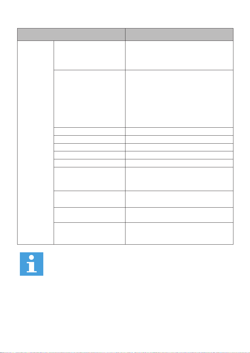
THE TECHNICAL DATA OF THE VACON® 100 FAMILY AC DRIVES
Technical item or function Technical data
Mains connection
Motor connection
Input voltage U
Input frequency 50-60 Hz, -5...+10%
Connection to mains Once per minute or less
Starting delay 6 s (MR4 to MR6), 8 s (MR7 to MR12)
Mains
Output voltage 0-U
Continuous output
current
Output frequency 0-320 Hz (standard)
Frequency resolution 0.01 Hz
in
208-240V, 380-500V, 525-600V,
525-690V,-10%…+10% *
• Mains types: TN, TT, and IT
• Short circuit current:
the maximum short circuit current
must be < 100 kA.
in
IL: Ambient temperature max. +40 °C
overload 1.1 x IL (1 min/10 min)
IH: Ambient temperature max. +50 °C
overload 1.5 x IH (1 min/10 min)
IH in 600/690 V drives and MR10-MR12:
Ambient temperature max. +40 °C
overload 1.5 x IH (1 min/10 min)
6
Page 7
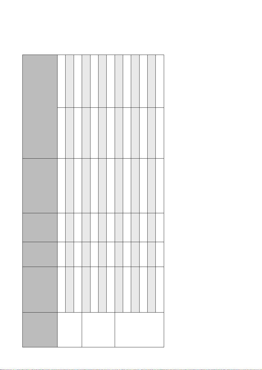
Technical item or function Technical data
Mains voltage 240 V: 456 VDC
Protections
Overvoltage
trip limit
Undervoltage trip limit
Earth fault protection Yes
Mains supervision Yes
Motor phase supervision Yes
Overcurrent protection Yes
Unit overtemp. protection Yes
Motor overload protection
Motor stall protection Yes
Mains voltage 500 V: 911 VDC
Mains voltage 600 V: 1094 VDC
Mains voltage 690 V: 1258 VDC
Depends on mains voltage
(0.8775 x mains voltage):
Mains voltage 240 V: trip limit 211 VDC
Mains voltage 400 V: trip limit 351 VDC
Mains voltage 500 V: trip limit 438 VDC
Mains voltage 525 V: trip limit 461 VDC
Mains voltage 600 V: trip limit 527 VDC
Mains voltage 690 V: trip limit 606 VDC
Yes. **
The motor overload protection activates
at 110% of the full load current.
Motor underload
protection
Short-circuit protection of
+24 V and +10 Vreference
voltages
Yes
Yes
NOTE!
The UL approval is valid for input voltage up to 600 V.
* = 525-600 V or 690 V are not available for VACON® 100 HVAC.
** = For the motor thermal memory and the memory retention function to obey
the UL 61800-5-1 requirements, you must use the system software version
FW0072V007 for VACON® 100 INDUSTRIAL, FW0159V003 for VACON® 100 FLOW,
and FW0065V021 for VACON® 100 HVAC, or a newer version. If you use an older
system software version, you must install a motor overtemperature protection to
obey the UL regulations.
7
Page 8

THE CABLE AND FUSE SIZES FOR VACON® 100 FAMILY
IN NORTH AMERICA, MAINS VOLTAGE 208240 V AND 380500 V
[AWG/kcmil]
Ground terminal
Terminal cable size
terminal
Mains cable
[AWG/kcmil]
and brake
Mains, motor
(Cu) [AWG]
resistor* cable
Fuse
(class
T/J) [A]
Type IL [A]
0003 2 / 0003 5 3.7 / 3.4 6 14 24-10 17-10
0004 2 / 0004 5 4.8 6 14 24-10 17-10
0006 2 / 0005 5 6.6 / 5.6 10 14 24-10 17-10
0008 2 / 0008 5 8.0 10 14 24-10 17-10
0011 2 / 0009 5 11.0 / 9.6 15 14 24-10 17-10
0012 2 / 0012 5 12.5 / 12.0 20 14 24-10 17-10
0018 2 / 0016 5 18.0 / 16.0 25 10 20-6 17-8
0024 2 / 0023 5 24.0 / 23.0 30 10 20-6 17-8
0031 2 / 0031 5 31.0 40 8 20-6 17-8
0038 5 38.0 50 4 13-0 13-2
0048 2 / 0046 5 48.0 / 46.0 60 4 13-0 13-2
0062 2 / 0061 5 ** 62.0 / 61.0 80 4 13-0 13-2
0075 2 / 0072 5 75.0 / 72.0 100 2 9-2/0 9-2/0
0088 2 / 0087 5 88.0 / 87.0 110 1 9-2/0 9-2/0
0105 2 / 0105 5 105.0 150 1/0 9-2/0 9-2/0
0140 2 / 0140 5 140.0 200 3/0 1 AWG-350 kcmil 1 AWG-350 kcmil
0170 2 / 0170 5 170.0 225 250 kcmil 1 AWG-350 kcmil 1 AWG-350 kcmil
0205 2 / 0205 5 205.0 250 350 kcmil 1 AWG-350 kcmil 1 AWG-350 kcmil
size
Enclosure
8
MR4
MR5
MR6
MR7
MR8
Page 9

Terminal cable size
Mains cable
and brake
Mains, motor
Fuse
Ground terminal
terminal
resistor* cable
(class
T/J) [A]
[AWG/kcmil]
[AWG/kcmil]
(Cu) [AWG]
Type IL [A]
Enclosure
size
0261 2 / 0261 5 261.0 350 2x250 kcmil 1 AWG-350 kcmil 1 AWG-350 kcmil
MR9
0310 2 / 0310 5 310.0 400 2x350 kcmil 1 AWG-350 kcmil 1 AWG-350 kcmil
0385 5 385 500 2x250 kcmil 1 AWG-350 kcmil 1 AWG-350 kcmil
0460 5 460 600 2x350 kcmil 1 AWG-350 kcmil 1 AWG-350 kcmil
MR10
0520 5 520 700 3x4/0 1 AWG-350 kcmil 1 AWG-350 kcmil
0590 5 590 800 3x250 kcmil 1 AWG-350 kcmil 1 AWG-350 kcmil
0650 5 650 2x400 4x4/0 1 AWG-350 kcmil 1 AWG-350 kcmil
0730 5 730 2x500 4x300 1 AWG-350 kcmil 1 AWG-350 kcmil
0820 5 820 2x600 4x350 1 AWG-350 kcmil 1 AWG-350 kcmil
MR12
0920 5 920 2x600 6x4/0 1 AWG-350 kcmil 1 AWG-350 kcmil
1040 5 1040 2x600 6x250 1 AWG-350 kcmil 1 AWG-350 kcmil
1180 5 1180 2x700 6x300 1 AWG-350 kcmil 1 AWG-350 kcmil
also possible to use a single cable if you obey the minimum cross-sectional area of the cable.
* = If you use a multi-conductor cable, 1 of the conductors of the brake resistor cable stays unconnected. It is
** = To obey the UL regulations with the 500 V drive, it is necessary to have cables with a +194 °F
heat resistance.
9
Page 10

THE CABLE AND FUSE SIZES FOR VACON® 100 FAMILY
IN NORTH AMERICA, MAINS VOLTAGE 525600 V
[AWG/kcmil]
Ground terminal
Terminal cable size
terminal
Mains cable
[AWG/kcmil]
brake resistor*
cable (Cu) [AWG]
Mains, motor and
10
Fuse
(class T)
Type IL [A]
Enclosure
[A]
size
0004 6 3.9 6 14 20-6 17-8
0006 6 6.1 10 14 20-6 17-8
MR5
0009 6 9.0 10 14 20-6 17-8
0011 6 11.0 15 14 20-6 17-8
(600V)
0007 7 7.5 10 12 13-0 13-2
0010 7 10.0 15 12 13-0 13-2
0013 7 13.5 20 12 13-0 13-2
0018 6 / 0018 7 18.0 20 10 13-0 13-2
MR6
0022 6 / 0022 7 22.0 25 10 13-0 13-2
0027 7 / 0027 7 27.0 30 8 13-0 13-2
0034 6 / 0034 7 34.0 40 8 13-0 13-2
0041 6 / 0041 7 41.0 50 6 9-2/0 9-2/0
0052 6 / 0052 7 52.0 60 6 9-2/0 9-2/0
MR7
0062 6 / 0062 7 62.0 70 4 9-2/0 9-2/0
0080 6 / 0080 7 80.0 90 1/0 1 AWG-350 kcmil 1 AWG-350 kcmil
0100 6 / 0100 7 100.0 110 1/0 1 AWG-350 kcmil 1 AWG-350 kcmil
MR8
0125 6 / 0125 7 125.0 150 2/0 1 AWG-350 kcmil 1 AWG-350 kcmil
Page 11
Terminal cable size
Mains cable
Mains, motor and
Fuse
Ground terminal
terminal
brake resistor*
(class T)
[AWG/kcmil]
[AWG/kcmil]
cable (Cu) [AWG]
[A]
Type IL [A]
Enclosure
size
0144 6 / 0144 7 144.0 175 3/0 1 AWG-350 kcmil 1 AWG-350 kcmil
0170 7 170.0 200 4/0 1 AWG-350 kcmil 1 AWG-350 kcmil
MR9
0208 6 / 0208 7 208.0 250 300 kcmil 1 AWG-350 kcmil 1 AWG-350 kcmil
0261 7 261.0 350 2xAWG2/0 1 AWG-350 kcmil 1 AWG-350 kcmil
0325 7 325.0 450 2x4/0 1 AWG-350 kcmil 1 AWG-350 kcmil
MR10
0385 7 385.0 500 2x250 kcmil 1 AWG-350 kcmil 1 AWG-350 kcmil
0416 7 416.0 600 2x300 kcmil 1 AWG-350 kcmil 1 AWG-350 kcmil
0460 7 460 2x300 4x2/0 1 AWG-350 kcmil 1 AWG-350 kcmil
0520 7 520 2x350 4x3/0 1 AWG-350 kcmil 1 AWG-350 kcmil
0590 7 590 2x400 4x4/0 1 AWG-350 kcmil 1 AWG-350 kcmil
MR12
0650 7 650 2x400 4x4/0 1 AWG-350 kcmil 1 AWG-350 kcmil
0750 7 750 2x450 4x300 1 AWG-350 kcmil 1 AWG-350 kcmil
0820 7 820 2x500 4x350 1 AWG-350 kcmil 1 AWG-350 kcmil
* = If you use a multi-conductor cable, 1 of the conductors of the brake resistor cable stays unconnected.
It is also possible to use a single cable if you obey the minimum cross-sectional area of the cable.
11
Page 12

THE TIGHTENING TORQUES OF CABLE TERMINALS
Tightening torque:
grounding conductor
the grounding clamps for
shield
the grounding
clamps for cable
Tightening torque:
12
Tightening torque:
the mains cable and
motor cable terminals
Type
size
Enclosure
Nm lb-in. Nm lb-in. Nm lb-in.
0.5-0.6 4.5-5.3 1.5 13.3 2.0 17.7
0003 2 - 0012 2
MR4
1.2-1.5 10.6-13.3 1.5 13.3 2.0 17.7
0003 5 - 0012 5
0018 2 - 0031 2
0016 5 - 0031 5
0004 6 - 0011 6
MR5
10 88.5 1.5 13.3 2.0 17.7
0048 2 - 0062 2
0038 5 - 0061 5
0018 6 - 0034 6
0007 7 - 0034 7
0075 2 - 0105 2
MR6
20 177 1.5 13.3 20 177
8 * / 5.6 ** 70.8 * / 49.6 ** 1.5 13.3 8 * / 5.6 ** 70.8 * / 49.6 **
0072 5 - 0105 5
0041 6 - 0062 6
0041 7 - 0062 7
0140 2 - 0205 2
0140 5 - 0205 5
MR7
MR8
0080 6 - 0125 6
0080 7 - 0125 7
Page 13

Tightening torque:
Tightening torque:
the grounding
grounding conductor
the grounding clamps for
shield
clamps for cable
Tightening torque:
the mains cable and
motor cable terminals
Type
size
Enclosure
Nm lb-in. Nm lb-in. Nm lb-in.
40 354 1.5 13.3 20 177
0261 2 - 0310 2
0261 5 - 0310 5
0144 6 - 0208 6
MR9
55-70 * 490-620 * 1.5 13.3 20 177
0144 7 - 0208 7
0385 5 - 0590 5
0261 6 - 0416 6
0261 7 - 0461 7
MR10
55-70 * 490-620 * 1.5 13.3 20 177
0650 5 - 1180 5
0460 6 - 0820 6
0460 7 - 0820 7
MR12
* = The tightening torque for a torx screw.
** = The tightening torque for an Allen screw.
13
Page 14

Page 15

Page 16

Download and read VACON® 100 Family
Installation manuals at:
http://drives.danfoss.com/knowledge-center/technical-documentation/
DPD01758E
 Loading...