

Page 1
VACON® 100 FAMILY AC DRIVES
QUICK GUIDE
GUIDE RAPIDE
KURZANLEITUNG
GUIDA RAPIDA
GUÍA RÁPIDA
GUIA RÁPIDO
快速指南
PIKAOPAS
EN
FR
DE
IT
ES
PTBR
ZH
FI
Page 2

Page 3

TOC
COOLING / REFROIDISSEMENT / KÜHLUNG / RAFFREDDAMENTO /
REFRIGERACIÓN / REFRIGERAÇÃO / 冷却 / JÄÄHDYTYS ................................4
CABLE INSTALLATION / INSTALLATION DES CÂBLES / KABELINSTALLATION /
INSTALLAZIONE DEI CAVI / INSTALACIÓN DE LOS CABLES /
INSTALAÇÃO DO CABO / 电缆安装 / KAAPELIEN ASENNUS .........................5
CONTROL PANEL AND KEYPAD ........................................................................6
EN
CONTROL TERMINALS ......................................................................................7
BASIC MENU STRUCTURE ................................................................................8
FIRST STARTUP ...............................................................................................9
PANNEAU OPÉRATEUR ...................................................................................10
FR
BORNES DE COMMANDE ................................................................................11
STRUCTURE DE MENU DE BASE ...................................................................12
PREMIÈRE MISE EN SERVICE ........................................................................13
STEUERTAFEL UND TASTENFELD ..................................................................14
DE
STEUERANSCHLÜSSE .....................................................................................15
BASISMENÜSTRUKTUR ................................................................................16
ERSTES ANLAUFEN ........................................................................................17
PANNELLO DI CONTROLLO E PANNELLO DI COMANDO ...............................18
IT
MORSETTI DI CONTROLLO ..............................................................................19
STRUTTURA DI BASE DEI MENU ....................................................................20
PRIMO AVVIO ...................................................................................................21
CUADRO DE CONTROL Y PANEL .....................................................................22
ES
TERMINALES DE CONTROL ............................................................................23
ESTRUCTURA BÁSICA DE MENÚS .................................................................24
PRIMERA PUESTA EN MARCHA .....................................................................25
PT-
PAINEL DE CONTROLE E TECLADO ................................................................26
BR
TERMINAIS DE CONTROLE .............................................................................27
ESTRUTURA BÁSICA DO MENU .....................................................................28
PRIMEIRA INICIALIZAÇÃO ..............................................................................29
控制面板和键盘 ................................................................................................30
ZH
控制端子 ...........................................................................................................31
基本菜单结构 ...................................................................................................32
首次启动 ...........................................................................................................33
OHJAUSPANEELI .............................................................................................34
FI
OHJAUSLIITTIMET ...........................................................................................35
PERUSVALIKKORAKENNE ..............................................................................36
ENSIMMÄINEN KÄYNNISTYS..........................................................................37
DISPOSAL / MISE AU REBUT / ENTSORGUNG / SMALTIMENTO /
ELIMINACIÓN / DESCARTE / 处置 / HÄVITTÄMINEN ....................................... 38
3
Page 4
COOLING / REFROIDISSEMENT / KÜHLUNG / RAFFREDDAMENTO /
EN
REFRIGERACIÓN / REFRIGERAÇÃO / 冷却 / JÄÄHDYTYS
FR
DE
IT
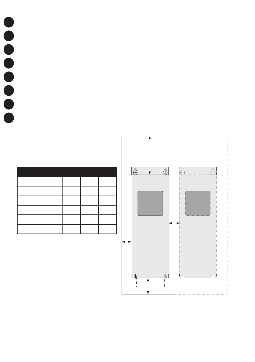
The minimum clearance [mm] around the drive
Dégagement minimal [mm] autour du convertisseur
Der Mindestabstand [mm] um den Umrichter herum
ES
PTBR
Distanza minima [mm] intorno all’inverter
La separación mínima [mm] alrededor del convertidor
Espaço livre mínimo [mm] ao redor do conversor
ZH
FI
变频器周围的间隙
Vähimmäisilmavälit [mm] taajuusmuuttajan ympärillä
FRAME A B C D
MR4 20 20 100 50
MR5 20 20 120 60
MR6 20 20 160 80
MR7 20 20 250 100
MR8 20 20 300 150
MR9 20 20 300 200
C
B
A
D
4
Page 5
CABLE INSTALLATION / INSTALLATION DES CÂBLES /
KABELINSTALLATION / INSTALLAZIONE DEI CAVI /
INSTALACIÓN DE LOS CABLES / INSTALAÇÃO DO CABO /
电缆安装 / KAAPELIEN ASENNUS
EN
FR
DE
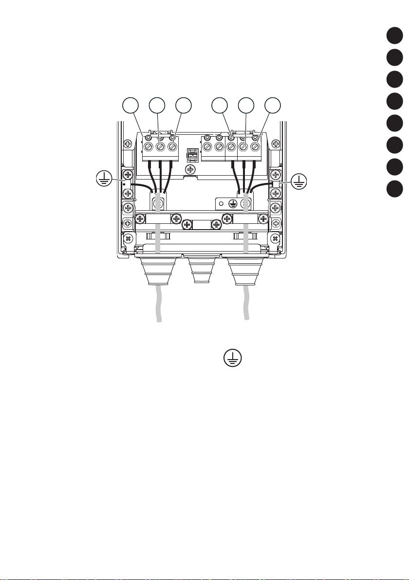
LI, L2, L3
Mains
Réseau
Netz
Rete elettrica
Red eléctrica
Rede elétrica
电源
Verkkovirta
L1 L2 L3 U V W
U, V, W
Motor
Moteur
Motor
Motore
Motor
Motor
电机
Moottori
The earth conductor
Le conducteur de terre
Erdungsleiter
Conduttore di terra
El conductor de toma a tierra
Condutor de aterramento
接地导线
Maadoitusjohdin
IT
ES
PTBR
ZH
FI
5
Page 6
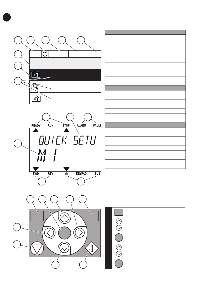
CONTROL PANEL AND KEYPAD
( 12 )
EN
A.
4 5 6 7 8
1
2
3
B.
12
STOP READY I/O
Main Menu
ID: M1
Quick Setup
( 17 )
Monitor
( 5 )
Parameters
9 10
11
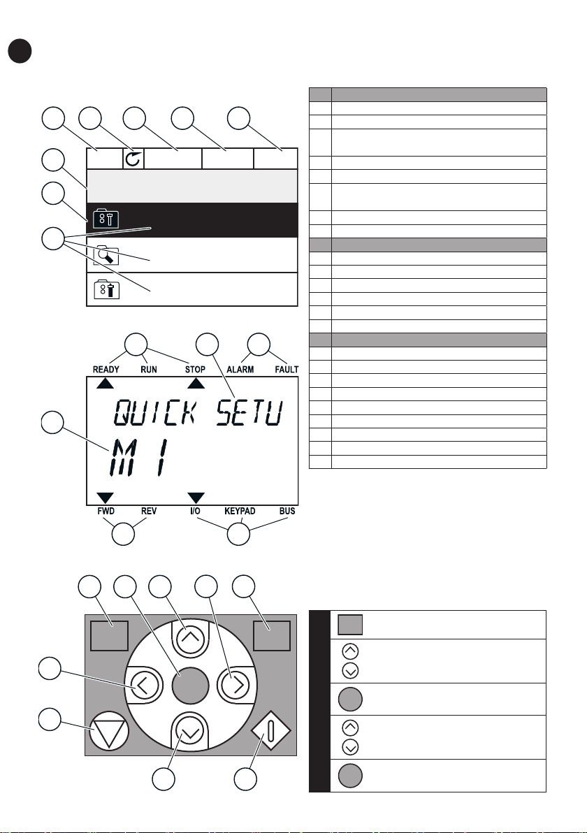
A The graphical display
1 The location field
2 An activated group or item
The number of items in the group in
3
question
4 The first status field: STOP/RUN
5 The rotation direction
The second status field: READY/NOT
6
READY/FAULT
7 The alarm field
8 The control place
B The text display
9 The indicators of status
10 The indicators of alarm and fault
11 The name of the group or item
12 The current location in the menu
13 The indicators of the rotation direction
14 The indicators of the control place
C The buttons of the keypad
15 The BACK/RESET button
16 The OK button
17 The arrow button UP
18 The FUNCT button
19 The arrow button RIGHT
20 The START button
21 The arrow button DOWN
22 The STOP button
23 The arrow button LEFT
FUNCT (18)
C.
23
15
BACK
RESET
16 17
19
1413
18
FUNCT
Use it to change the rotation direction of
the motor, access the control page, and
change the control place.
Changing the control place:
FUNCT
1.
2.
‘Local/Remote’
OK
OK
3.
22
4.
6
21
20
5.
‘Local’ or ‘Remote’
OK
Page 7
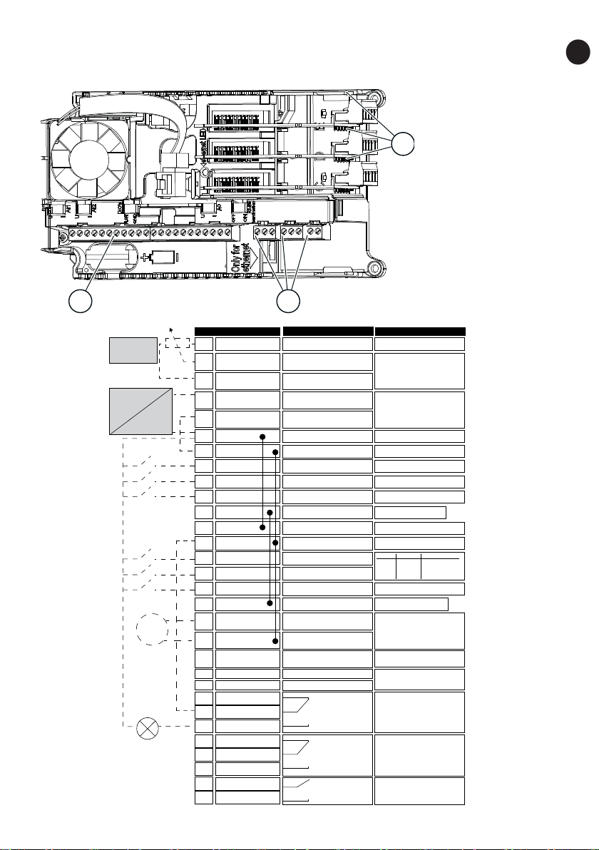
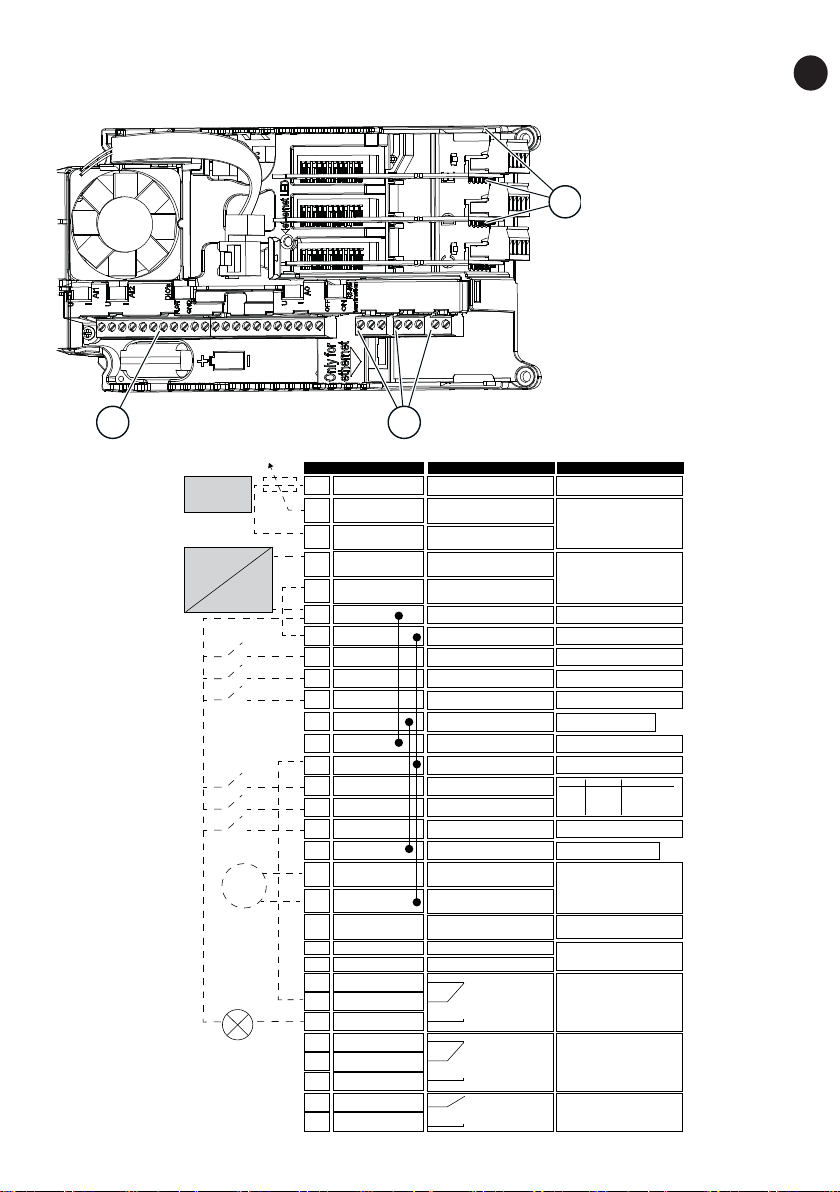
CONTROL TERMINALS
Standard I/O board
1. The terminals for
the standard I/O
connections
3
2. The terminals for 3
relay outputs or 2
relay outputs and
a thermistor
3. The option boards
EN
1
Reference
potentiometer
1...10kΩ
2-wire transmitter
Actual value
I = (0)4...20mA
mA
RUN
Terminal
+10 Vref
1
AI1+2
AI1-3
AI2+4
AI2-5
24Vout6
GND7
DI18
DI29
DI310
CM11
24Vout
12
GND13
DI414
DI515
DI616
17
CM
AO1+
18
AO1-/GND19
+24Vin30
RS485A
B
RS485
RO1 NC21
22
RO1 CM
RO1 NO23
RO2 NC24
25
RO2 CM
RO2 NO26
32
RO3 CM
RO3 NO33
2
Signal
Reference output
Analogue input,
voltage or current
Analogue input
common, (current)
Analogue input,
voltage or current
Analogue input
common, (current)
24V auxiliary voltage
I/O ground
Digital input 1
Digital input 2
Digital input 3
Common for DI1-DI6
24V auxiliary voltage
I/O ground
Digital input 4
Digital input 5
Digital input 6
Common for DI1-DI6
Analogue signal
(+output)
Analogue output
common / I/O ground
24V auxiliary
input voltage
Serial bus, negative
Serial bus, positive
Relay output 1
Relay output 2
Relay output 3
Description
Frequency reference
Frequency reference
Start forward
Start reverse
External fault
DI4 DI5 Freq. ref.
Open
Open
Closed
Open
Closed
Analog input 1
Open
Preset Freq. 1
Closed
Preset Freq. 2
Closed
Preset Freq. 3
Fault reset
Output frequency
Modbus RTU
BACnet, N2
RUN
FAU LT
READY
*)
*)
7
Page 8

BASIC MENU STRUCTURE
EN
Main menu Submenus
M1
Quick setup
M2
Monitor
M3
Parameters
M1.1 Wizards
(Content depends on
P1.2, App select.)
M2.1 Multimonitor
M2.2 Trend Curve
M2.3 Basic
M2.4 I/O
M2.5 Temperat. inputs
M2.6 Extras/Advanced
M2.7 Timer Functions
M2.8 PID Controller
M2.9 Ext PID Controller
M2.10 Multi-Pump
M2.11 Mainten.count.
M2.12 Fieldbus data
M3.1 Motor Settings
M3.2 Start/Stop Setup
M3.3 References
M3.4 Ramps and Brakes
M3.5 I/O Configuration
M3.6 FB Data Mapping
M3.7 Prohibit Freq
M3.8 Supervisions
M3.9 Protections
M3.10 Automatic Reset
M3.12 Timer Functions
M3.13 PID Controller
M3.14 Ext PID Ctrl
M3.15 Multi-Pump
M3.16 Mainten. cntrs
M3.17 Fire Mode
M3.18 Motor Preheat
M3.20 Mechanical Brake
M3.21 Pump Control
Main menu Submenus
M4
Diagnostics
M5
I/O and
Hardware
M6
User Settings
M7
Favourites
M8
User Levels
M4.1 Active Faults
M4.2 Reset Faults
M4.3 Fault history
M4.4 Total Counters
M4.5 Trip Counters
M4.6 Software Info
M5.1 I/O and Hardware
M5.2...M5.4 Slots C,D,E
M5.5 Real Time Clock
M5.6 Power unit sett.
M5.7 Keypad
M5.8 RS-485
M6.1 Language select.
M6.5 Parameter Backup
M6.7 Drive Name
M8.1 User Level
M8.2 Access Code
8
Page 9

FIRST START-UP
The Start-up wizard tells you to give necessary data for the drive to control your procedure.
The selection is different
1 Language selection (P6.1)
2 Daylight saving* (P5.5.5)
3 Time* (P5.5.2) hh:mm:ss
4 Year* (P5.5.4) yyyy
5 Date* (P5.5.3) dd.mm.
* If a battery is installed, you see these steps.
6 Run Startup wizard?
To set the parameter values manually, make the selection No and push the OK button.
7 Make a selection of an application (P1.2 Application, ID212)
Set a value for P3.1.2.2 Motor Type (so that it agrees with
8
the nameplate)
Set a value for P3.1.1.1 Motor Nominal Voltage (so that it
9
agrees with the nameplate)
Set a value for P3.1.1.2 Motor Nominal Frequency (so that
10
it agrees with the nameplate)
Set a value for P3.1.1.3 Motor Nominal Speed (so that it
11
agrees with the nameplate)
12 Set a value for P3.1.1.4 Motor Nominal Current Range: Varies
13 Set a value for P3.1.1.5 Motor Cos Phi Range: 0.30-1.00
If you set Motor Type to Induction Motor, you see the next step. If your selection is PM
Motor, the value of parameter P3.1.1.5 Motor Cos Phi is set to 1.00 and the wizard goes
directly to step 14.
14 Set a value for P3.3.1.1 Minimum Frequency Reference Range: 0.00...P3.3.1.2 Hz
15 Set a value for P3.3.1.2 Maximum Frequency Reference
16 Set a value for P3.4.1.2 Acceleration Time 1 Range: 0.1...300.0 s
17 Set a value for P3.4.1.3 Deceleration Time 1 Range: 0.1...300.0 s
18 Run the Application wizard?
in all the language
packages
Russia
US
EU
OFF
Yes
No
Standard
Local/Remote
Multi-step speed
PID control
Multi-purpose
Motor potentiometer
PM motor
Induction motor
Reluctance motor
Range: Varies
Range: 8.00...320.00 Hz
Range: 24...19200
Range: P3.3.1.1...320.00
Hz
Yes
No
EN
9
Page 10
PANNEAU OPÉRATEUR
( 12 )
FR
A.
4 5 6 7 8
1
2
3
B.
12
STOP READY I/O
Main Menu
ID: M1
Quick Setup
( 17 )
Monitor
( 5 )
Parameters
9 10
11
A L’affichage graphique
1 Champ de localisation
2 Groupe ou élément activé
Nombre d’éléments dans le groupe
3
en question
Premier champ d’état :
4
ARRÊT/MARCHE
5 Sens de rotation
Deuxième champ d’état :
6
PRÊT/PAS PRÊT/DÉFAUT
7 Champ d’alarme
8 Source de commande
B L’affichage textuel
9 Indicateurs d’état
10 Indicateurs d’alarme et de défaut
11 Nom du groupe ou de l’élément
12 Emplacement actuel dans le menu
13 Indicateurs du sens de rotation
Indicateurs de la source de
14
commande
C Boutons du panneau opérateur
15 Touche BACK/RESET
16 Touche OK
17 Touche HAUT
18 Touche FUNCT
19 Touche DROITE
20 Touche MARCHE
21 Touche BAS
22 Touche ARRÊT
23 Touche GAUCHE
10
C.
23
22
15
BACK
RESET
16 17
21
OK
19
1413
18
20
FUNCT
FUNCT (18)
Utilisez cette touche pour inverser le sens
de rotation du moteur, accéder à la page
de commande et modifier la source de
commande.
Modification de la source de commande :
FUNCT
1.
2.
3.
4.
‘Local/Distance’
OK
‘Local’ ou ‘Distance’
OK
5.
Page 11
BORNES DE COMMANDE
Carte d'E/S standard
T
1. Bornes de connexion
d’E/S standard
2. Bornes des 3 sorties
3
relais ou 2 sorties
relais et une thermistance
3. Cartes en option
FR
1
Potentiomètre
de référen ce
1...10 kΩ
ransmetteur 2 fils
Valeur réelle
I = (0)4...20 mA
mA
MARCHE
1
2
3
4
5
24 Vsortie
6
7
8
9
10
11
24 Vsortie Tension auxiliaire 24 V
12
13
14
15
16
17
18
19
30
+24 Ventrée
A
B
21
22
23
24
25
26
32
33
2
Borne Type de signal Description
+10 Vref
AI1+
AI1-
AI2+
AI2-
GND Terre E/S
DI1
DI2 Entrée logique 2
DI3
CM
GND Terr
DI4
DI5
DI6
CM Commun pour DI1-DI6
AO1+
AO1-/GND
RS485 Bus série, négatif
RS485
RO1 NC
RO1 CM
RO1 NO
RO2 NC
RO2 CM
RO2 NO
RO3 CM
RO3 NO
Sortie de référence
Entrée analogique,
tension ou courant
Entrée analogique
commune, (courant)
Entrée analogique,
tension ou courant
Entrée analogique
commune, (courant)
Tension auxiliaire 24 V
Entrée logique 1
Entrée logique 3
Commun pour DI1-DI6
e E/S
Entrée logique 4
Entrée logique 5
Entrée logique 6
Signal analogique
(+ sortie)
Commun sortie
analogique / terre E/S
Tension entrée
auxiliaire 24 V
Bus série, positif
Sortie relais 1
Sortie relais 2
Sortie relais 3
Référence de fréquence
Référence de fréquence
Marche avant
Marche arri
Défaut externe
DI4 DI5 Ré f. fréquence
Ouvert Ouvert
Ouvert
Fermé
Ouvert
Fermé
Fermé
Fermé
Réarmement défaut
Fréquence de sortie
Modbus RTU
BACnet, N2
MARCHE
DÉFAUT
PRÊT
ère
Entrée analog. 1
Vitesse cste 1
Vitesse cste 2
Vitesse cste 3
*)
*)
11
Page 12

STRUCTURE DE MENU DE BASE
FR
principal
Configuration
Affichage
Paramètres
12
Menu
M1
rapide
M2
M3
Sous-menus
M1.1 Assistants
(le contenu dépend de P1.2,
Sél. applicatif)
M2.1 Multi-affichage
M2.2 Courbe tdce
M2.3 Base
M2.4 E/S
M2.5 Entrées temp.
M2.6 Extras/Avancé
M2.7 Fctions retardat
M2.8 Régulateur PID
M2.9 Régulateur PID ext.
M2.10 Multi-pompe
M2.11 Cptrs maintenance
M2.12 Donnée bus
M3.1 Param. moteur
M3.2 Cfg Marche/Arrêt
M3.3 Références
M3.4 Rampes/Freinages
M3.5 Configuration E/S
M3.6 Mappage données bus
M3.7 Fréq. interdite
M3.8 Supervisions
M3.9 Protections
M3.10 Réarmement
automatique
M3.12 Fctions retardat
M3.13 Régulateur PID
M3.14 Régulateur PID ext.
M3.15 Multi-pompe
M3.16 Cptrs maintenance
M3.17 Mode incendie
M3.18 Préchauff moteur
M3.20 Frein mécanique
M3.21 Commande de la
pompe
Menu
principal
M4
Diagnostics
M5
I/O and
Hardware
M6
Réglages utilis.
M7
Favoris
M8
Niveaux utilisat.
Sous-menus
M4.1 Défauts actifs
M4.2 Réarmemt défauts
M4.3 Historiq défauts
M4.4 Cpteurs sans RAZ
M4.5 Cpteurs avec RAZ
M4.6 Infos logiciel
M5.1 E/S et matériel
M5.2...M5.4
Emplacements C,D,E
M5.5 Horloge tps réel
M5.6 Régl.unit.puiss.
M5.7 Panneau opér.
M5.8 RS-485
M6.1 Sélection langue
M6.5 Sauvegarde param
M6.7 Nom convertiss.
M8.1 Niveaux utilisat.
M8.2 Code d’accès
Page 13

PREMIÈRE MISE EN SERVICE
L’assistant de mise en service vous demande de renseigner les données nécessaires pour
que convertisseur commande votre procédure.
La sélection est différente
1 Sélection de la langue (P6.1)
2 Heure d’été* (P5.5.5)
3 Heure* (P5.5.2) hh:mm:ss
4 Année* (P5.5.4) aaaa
5 Date* (P5.5.3) jj.mm.
* Vous pouvez voir ces étapes si une batterie est installée.
6 Exécuter l’Assistant de mise en service ?
Pour définir manuellement les valeurs des paramètres, sélectionnez Non et appuyez sur OK.
7 Sélection d’un applicatif (P1.2 Applicatif, ID212)
Spécifiez la valeur du paramètre P3.1.2.2 Type de moteur
8
(conformément à la plaque signalétique)
Spécifiez la valeur du paramètre P3.1.1.1 Tension nominale moteur
9
(conformément à la plaque signalétique)
Spécifiez la valeur du paramètre P3.1.1.2 Fréquence nominale
10
moteur (conformément à la plaque signalétique)
Spécifiez la valeur du paramètre P3.1.1.3 Vitesse nominale moteur
11
(conformément à la plaque signalétique)
12 Spécifiez la valeur du paramètre P3.1.1.4 Courant nominal moteur Plage : Variable
13 Spécifiez la valeur du paramètre P3.1.1.5 Cos phi moteur Plage : 0.30-1.00
Si la valeur de Type de moteur est Moteur à induction, l’étape suivante s’affiche. Si vous sélectionnez
Moteur AP, la valeur du paramètre P3.1.1.5 Cos Phi moteur est 1,00 et l’assistant passe directement
à l’étape 14.
Spécifiez la valeur du paramètre P3.3.1.1 Référence de fréquence
14
minimale
Spécifiez la valeur du paramètre P3.3.1.2 Référence de fréquence
15
maximale
16 Spécifiez la valeur du paramètre P3.4.1.2 Temps d’accélération 1 Plage : 0,1...300,0 s
17 Spécifiez la valeur du paramètre P3.4.1.3 Temps de décélération 1 Plage : 0,1...300,0 s
18 Démarrer l’Assistant d’applicatif ?
dans tous les packs
linguistiques
Russie
US
EU
OFF
Oui
Non
Standard
Local/Distance
Commande séquentielle
Régulation PID
Multi-configuration
Motopotentiomètre
Moteur à aimants
permanents (AP)
Moteur à induction
Moteur à réluctance
Plage : Variable
Plage : 8,00...320,00 Hz
Plage : 24...19200
Plage : 0,00...P3.3.1.2 Hz
Plage : P3.3.1.1...320,00 Hz
Oui
Non
FR
13
Page 14

STEUERTAFEL UND TASTENFELD
( 12 )
DE
A.
4 5 6 7 8
1
2
3
B.
12
STOP READY I/O
Main Menu
ID: M1
Quick Setup
( 17 )
Monitor
( 5 )
Parameters
9 10
11
A Das Grafik-Display
1 Das Positionsfeld
Aktivierte Gruppe oder aktiviertes
2
Element
Anzahl der Elemente in der
3
betreffenden Gruppe
Das erste Statusfeld: STOPP/
4
BETRIEB
5 Die Drehrichtung des Motors
Das zweite Statusfeld: BEREIT/
6
NICHT BEREIT/FEHLER
7 Das Alarmfeld
8 Das Steuerplatzfeld
B Das Text-Display
9 Die Statusanzeigen
10 Die Alarm- und Fehleranzeigen
Der Name der Gruppe oder des
11
Elements
12 Die aktuelle Position im Menü
13 Die Drehrichtungsanzeigen
14 Die Steuerplatzanzeigen
C Die Tasten des Tastenfelds
15 BACK/RESET-Taste
16 OK-Taste
17 Pfeiltaste NACH OBEN
18 FUNCT-Taste
19 Pfeiltaste NACH RECHTS
20 START-Taste
21 Pfeiltaste NACH UNTEN
22 STOP-Taste
23 Pfeiltaste NACH LINKS
14
C.
23
22
15
BACK
RESET
16 17
21
OK
19
1413
18
20
FUNCT
FUNCT (18)
Drehrichtung des Motors ändern,
Steuerungsseite aufrufen und Steuerplatz
ändern.
Ändern des steuerplatzes:
FUNCT
1.
2.
3.
4.
‘Ort/Fern’
OK
‘Ort’ oder ‘Fern’
OK
5.
Page 15

STEUERANSCHLÜSSE
Standard-E/A-Karte
1. Klemmen für die E/A
Standard anschlüsse
2. Klemmen für 3 Re-
3
laisausgänge oder 2
Relaisausgänge und
einen Thermistor
3. Optionskarten
DE
1
Sollwertpotentiome ter
1 bis 10 kΩ
2-Anschluss-Geber
Istwert
I = (0)4 bis 20 mA
mA
RUN
(BETRIEB)
1
2
3
4
5
6
7
8
9
10
11
12
13
14
15
16
17
18
19
30
A
B
21
22
23
24
25
26
32
33
2
Klemme Signal Beschreibung
+10 Vref
AI1+
AI1-
AI2+
AI2-
24 Vout
GND E/A Masse
DI1
DI2 Digitalei ngang 2
DI3
CM
24 Vout 24 V Hilfsspannung
GND E/A Masse
DI4
DI5
DI6
CM
AO1+
AO1-/GND
+24 Vin
RS485 Serieller Bus, negativ
RS485
RO1 NC
RO1 CM
RO1 NO
RO2 NC
RO2 CM
RO2 NO
RO3 CM
RO3 NO
Sollausgang
Analogeingang,
Spannung oder Strom
Gemeinsamer
Analogeingang, (Strom)
Analogeingang,
Spannung oder Strom
Gemeinsamer
Analogeingang, (Strom)
24 V Hilfsspannung
Digitalei ngang 1
Digitalei ngang 3
Gemeinsamer Bezug
für DI1-DI6
Digitalei ngang 4
Digitalei ngang 5
Digitalei ngang 6
Gemeinsamer
Bezug für DI1-DI6
Analogsignal
(+-Ausgang)
Gemeinsamer
Analogausgang / E/A-Masse
24 V
Hilfseingangsspannung
Serieller Bus, positiv
Relaisausgang 1
Relaisausgang 2
Relaisausgang 3
Frequenzsollwert
Frequenzsollwert
Sta
rt vorwärts
Start rückwärts
Externer Fehle r
DI4 DI5 Fre q.sollw.
Offen Offen
Geschlossen
Offen
Geschlossen
Fehlerquittierung
Analogeingang 1
Offen
Festfrequenz 1
Geschlossen
Festfrequenz 2
Geschlossen
Festfrequenz 3
Ausgangsfrequenz
Modbus RTU
BACnet, N2
RUN (BETRIEB)
FAULT (FEHLER)
READY (BEREIT)
*)
*)
15
Page 16

BASISMENÜSTRUKTUR
DE
Hauptmenü Untermenüs
M1
Schnellein-
stellungen
M2
Monitor
M3
Parameter
16
M1.1 Wizards
(Content depends on
P1.2, App select.)
M2.1 Multimonitor
M2.2 Trendkurve
M2.3 Basis
M2.4 E/A
M2.5 Temperat. Eingänge
M2.6 Extras/Erweitert
M2.7 Timerfunktionen
M2.8 PID-Regler
M2.9 Ext PID Controller
M2.10 Multi-Pump
M2.11 Wartungszähler
M2.12 Feldbusdaten
M3.1 Motoreinstellung
M3.2 Start/Stopp-Einst
M3.3 Sollwerte
M3.4 Rampen & Bremsen
M3.5 E/A-Konfiguration
M3.6 FB Datenzuordnung
M3.7 Freq.ausblendung
M3.8 Überwachungen
M3.9 Schutzfunktionen
M3.10 Automatische
Fehlerquittierung
M3.12 Timerfunktionen
M3.13 PID-Regler
M3.14 Ext. PID-Regler
M3.15 Multi-Pump
M3.16 Wartungszähler
M3.17 Brand-Modus
M3.18 Motor Vorheizung
M3.20 Mechanische
Bremse
M3.21 Pumpenregelung
Hauptmenü Untermenüs
M4
Fehlerspeicher
M5
E/A und
Hardware
M6
Benutzereinstell.
M7
Favoriten
M8
Anwendergruppen
M4.1 Aktive Fehler
M4.2 Fehler quittieren
M4.3 Fehlerspeicher
M4.4 Gesamtzähler
M4.5 RückstellbZähler
M4.6 Software-Info
M5.1 E/A und Hardware
M5.2 bis M5.4 St.pl.
C,D,E
M5.5 Echtzeituhr
M5.6 Leistungseinh.
Einst.
M5.7 Steuertafel
M5.8 RS-485
M6.1 Sprachwahl
M6.5 Parameter-Backup
M6.7 Name d. FU
M8.1 Anwendergruppe
M8.2 Zugangscode
Page 17

ERSTES ANLAUFEN
Der Anlaufassistent fordert Sie zur Eingabe der Daten auf, die der Umrichter zur Steuerung
Ihres Verfahrens benötigt.
1 Sprachenauswahl (P6.1)
2 Sommerzeit* (P5.5.5)
3 Zeit* (P5.5.2) hh:mm:ss
4 Jahr* (P5.5.4) JJJJ
5 Datum* (P5.5.3) tt.mm.
* Diese Schritte werden angezeigt, wenn eine Batterie eingebaut ist.
6 Anlaufassistenten ausführen?
Um die Parameterwerte manuell festzulegen, wählen Sie Nein bestätigen Sie mit OK.
7 Wählen Sie eine Anwendung (P1.2 Anwendung, ID212)
Stellen Sie den Wert für P3.1.2.2 Motortyp ein (siehe
8
Typenschild).
Stellen Sie den Wert für P3.1.1.1 Motornennspannung ein
9
(siehe Typenschild).
Stellen Sie den Wert für P3.1.1.2 Motornennfrequenz ein
10
(siehe Typenschild).
Stellen Sie den Wert für P3.1.1.3 Motornenndrehzahl ein
11
(siehe Typenschild).
12 Stellen Sie den Wert für P3.1.1.4 Motornennstrom ein. Bereich: variiert
13 Stellen Sie den Wert für P3.1.1.5 Motor Cos Phi ein. Bereich: 0.30-1.00
Wenn unter „Motortyp“ die Option Asynchronmotor ausgewählt wurde, wird der nächste Schritt
angezeigt. Falls PM-Motor ausgewählt wurde, wird für den Parameter P3.1.1.5 Motor Cos Phi der
Wert 1,00 eingestellt, und der Assistent fährt direkt mit Schritt 14 fort.
Stellen Sie den Wert für P3.3.1.1 Sollwert Mindestfrequenz
14
ein.
15 Stellen Sie den Wert für P3.3.1.2 Sollwert Höchstfrequenz ein. Bereich: P3.3.1.1 bis 320,00 Hz
16 Stellen Sie den Wert für P3.4.1.2 Beschleunigungszeit 1 ein. Bereich: 0,1 bis 300,0 s
17 Stellen Sie den Wert für P3.4.1.3 Bremszeit 1 ein. Bereich: 0,1 bis 300,0 s
18 Anwendungsassistenten ausführen?
Die Auswahl ist in
allen Sprachpaketen
unterschiedlich.
Russland
US
EU
AUS
Ja
Nein
Standard
Ort/Fern
Mehrstufige Drehzahl
PID-Regler
Mehrzweck
Motorpotentiometer
PM-Motor
Asynchronmotor
Reluktanzmotor
Bereich: variiert
Bereich: 8,00 bis 320,00 Hz
Bereich: 24...19200
Bereich: 0,00 bis P3.3.1.2 Hz
Ja
Nein
DE
17
Page 18

PANNELLO DI CONTROLLO E PANNELLO DI COMANDO
( 12 )
IT
A.
4 5 6 7 8
1
2
3
B.
12
STOP READY I/O
Main Menu
ID: M1
Quick Setup
( 17 )
Monitor
( 5 )
Parameters
9 10
11
A Il display grafico
1 Il campo della posizione
2 Un gruppo o un elemento attivato
Il numero di elementi nel gruppo in
3
questione
Il primo campo dello stato:
4
Arresto/Marcia
5 La direzione di rotazione del motore
Il secondo campo dello stato:
6
Pronto/Non pronto/Guasto
7 Il campo di allarme
8 Il campo della postazione di controllo
B Il display di testo
9 Gli indicatori di stato
10 Gli indicatori di allarme e guasto
11 Il nome del gruppo o dell’elemento
La posizione corrente nel menu
12
corrente
Gli indicatori della direzione di
13
rotazione
Gli indicatori della postazione di
14
controllo
C Pulsanti del pannello di comando
15 Pulsante BACK/RESET
16 Pulsante OK
17 Pulsante freccia Su
18 Pulsante FUNCT
19 Pulsante freccia Destra
20 Pulsante Avvio
21 Pulsante freccia Giù
22 Pulsante Arresto
23 Pulsante freccia Sinistra
18
C.
23
22
15
BACK
RESET
16 17
21
OK
19
1413
18
20
FUNCT
FUNCT (18)
Utilizzarlo per modificare la direzione di
rotazione del motore, per accedere alla
pagina di controllo e per scambiare le
postazioni di controllo.
Cambio della postazione di controllo:
FUNCT
1.
2.
3.
4.
‘Locale/Remoto’
OK
‘Locale’ o ‘Remoto’
OK
5.
Page 19

MORSETTI DI CONTROLLO
Scheda I/O standard
1. Morsetti per
connessioni I/O
standard
3
2. Morsetti per 3 uscite
relè o 2 uscite relè
e un termistore
3. Schede opzionali
IT
1
Potenziometro
di riferime nto
1 - 10 kΩ
Trasmettitore a 2 fili
Valore
effettivo
I = (0)4...20 mA
mA
MARCIA
Morsetto Segnale Descrizione
+10 Vref
1
2
AI1+
3
AI1-
4
AI2+
5
AI2-
24 Vout
6
7
GND Massa I/O
8
DI1
9
DI2 Ingresso digi
10
DI3
CM
11
24 Vout Tensione ausiliaria 24 V
12
GND Massa I/O
13
14
DI4
15
DI5
DI6
16
17
CM Comune per DI1-DI6
AO1+
18
19
AO1-/GND
30
+24 Vin
RS485 Bus seriale, negativo
A
B
RS485
21
RO1 NC
22
RO1 CM
23
RO1 NO
RO2 NC
24
25
RO2 CM
26
RO2 NO
32
RO3 CM
33
RO3 NO
2
Uscita di riferimento
Ingresso analogico,
tensione o corrente
Comune per ingresso
analogico (corrente)
Ingresso analogico,
tensione o corrente
Comune per ingresso
analogico (corrente)
Tensione ausiliaria 24 V
Ingresso digitale 1
Ingresso digitale 3
Comune per DI1-DI6
Ingresso digitale 4
Ingresso digitale 5
Ingresso digitale 6
Segnale uscita
analogica (+)
Comune per uscita
analogica/massa I/O
Tensione ingresso
ausiliario 24 V
Bus seriale, positivo
Uscita relè
Uscita relè 2
Uscita relè 3
tale 2
1
Riferimento di
frequenza
Riferimento di
frequenza
Marcia avanti
Marcia indietro
Guasto esterno
DI4 DI5 Ri f. freq.
Aperto Aperto
Chiuso
Aperto
Chiuso
Reset guasti
Ingresso anal. 1
Aperto
Vel prefissata 1
Chiuso
Vel prefissata 2
Chiuso
Vel prefissata 3
Frequenza di uscita
Modbus RTU
BACnet, N2
MARCIA
GUASTO
PRONTO
*)
*)
19
Page 20

STRUTTURA DI BASE DEI MENU
IT
Menu principale Sottomenu
M1
Config. rapida
M2
Monitor
M3
Parametri
M1.1 Proc Guidate
(il contenuto dipende
da P1.2, Selez. app)
M2.1 Multimonitor
M2.2 Curva trend
M2.3 Base
M2.4 I/O
M2.5 Ingressi
temperatura
M2.6 Extra/Avanzati
M2.7 Funzioni timer
M2.8 Controllore PID
M2.9 Controllore PIDEst
M2.10 Multi-pompa
M2.11 Manut. Contatori
M2.12 Dati bus campo
M3.1 Impostaz. motore
M3.2 Conf marcia/arr.
M3.3 Riferimenti
M3.4 Rampe e freni
M3.5 Configurazione I/O
M3.6 Mappatura dati FB
M3.7 Freq. proibita
M3.8 Supervisioni
M3.9 Protezioni
M3.10 Reset automatico
M3.12 Funzioni timer
M3.13 Controller PID
M3.14 Ctrl PIDEst
M3.15 Multi-pompa
M3.16 Contatori di manut.
M3.17 Fire mode
M3.18 Prerisc. motore
M3.20 FrenoMeccanico
M3.21 Controllo pompa
20
Menu principale Sottomenu
M4
Diagnostica
M5
I/O e
hardware
M6
Impostaz. utente
M7
Valori preferiti
M8
Livelli utente
M4.1 Guasti attivi
M4.2 Reset guasti
M4.3 Memoria guasti
M4.4 Contatori totali
M4.5 Contatori parziali
M4.6 Info software
M5.1 I/O e hardware
M5.2...M5.4 Slot C,D,E
M5.5 Orol. tmp reale
M5.6 Impost. unità pot.
M5.7 Pannello di comando
M5.8 RS-485
M6.1 Scelta della lingua
M6.5 Backup parametri
M6.7 Nome inverter
M8.1 Livello utente
M8.2 Codice accesso
Page 21

PRIMO AVVIO
La procedura guidata di avvio richiede l’inserimento dei dati necessari all’inverter per il
controllo della procedura.
IT
1 Scelta della lingua (P6.1)
2 Ora legale* (P5.5.5)
3 Ora* (P5.5.2) hh:mm:ss
4 Anno* (P5.5.4) aaaa
5 Data* (P5.5.3) gg.mm.
* Se è installata una batteria, vengono visualizzati i seguenti passaggi.
6 Eseguire la procedura guidata di avvio?
Per impostare manualmente i valori dei parametri, selezionare No e premere il pulsante OK.
7 Selezionare un’applicazione (P1.2 Applicazione, ID212)
Impostare un valore per P3.1.2.2 Tipo di motore (affinché
8
corrisponda alla targhetta)
Impostare un valore per P3.1.1.1 Tensione nominale del
9
motore (affinché corrisponda alla targhetta)
Impostare un valore per P3.1.1.2 Frequenza nominale del
10
motore (affinché corrisponda alla targhetta)
Impostare un valore per P3.1.1.3 Velocità nominale del
11
motore (affinché corrisponda alla targhetta)
Impostare un valore per P3.1.1.4 Corrente nominale del
12
motore
13 Impostare un valore per P3.1.1.5 Cosfi motore Gamma: 0.30-1.00
Se si imposta Tipo motore su Motore a induzione, viene visualizzato il passo successivo. Se si
seleziona Motore PM, il valore del parametro P3.1.1.5 Cosfi motore viene impostato su 1,00 e la
procedura guidata va direttamente al passo 14.
Impostare un valore per P3.3.1.1 Riferimento di frequenza
14
minima
Impostare un valore per P3.3.1.2 Riferimento di frequenza
15
massima
16 Impostare un valore per P3.4.1.2 Tempo di accelerazione 1 Gamma: 0,1...300,0 s
17 Impostare un valore per P3.4.1.3 Tempo di decelerazione 1 Gamma: 0,1...300,0 s
18 Eseguire la procedura guidata applicazione?
La selezione differisce in
tutti i pacchetti di lingue
Russia
US
UE
OFF
Sì
No
Standard
Locale/remoto
Velocità multi step
Controllore PID
Multifunzione
Motopotenziometro
Motore PM
Motore a induzione
Motore a riluttanza
Gamma: Varie
Gamma: 8,00...320,00 Hz
Gamma: 24...19200
Gamma: Varie
Gamma: 0,00...P3.3.1.2 Hz
Gamma: P3.3.1.1...320,00 Hz
Sì
No
21
Page 22

CUADRO DE CONTROL Y PANEL
( 12 )
ES
A.
4 5 6 7 8
1
2
3
B.
12
STOP READY I/O
Main Menu
ID: M1
Quick Setup
( 17 )
Monitor
( 5 )
Parameters
9 10
11
A La pantalla gráfica
1 El campo de ubicación
2 Un grupo o elemento activado
El número de elementos del grupo
3
en cuestión
El primer campo de estado:
4
PARO/MARCHA
5 El sentido de giro del motor
El segundo campo de estado:
6
LISTO/NO LISTO/FALLO
7 El campo de alarma
8 El campo del lugar de control
B La pantalla de texto
9 Los indicadores de estado
10 Los indicadores de alarmas y fallos
11 El nombre del grupo o elemento
12 La ubicación actual en el menú
13 Los indicadores del sentido de giro
14 Los indicadores del lugar de control
C Los botones del panel
15 El botón BACK/RESET
16 El botón OK
17 El botón de flecha ARRIBA
18 El botón FUNCT
19 El botón de flecha DERECHA
20 El botón START
21 El botón de flecha ABAJO
22 El botón STOP
23 El botón de flecha IZQUIERDA
22
C.
23
22
15
BACK
RESET
16 17
21
OK
19
1413
18
20
FUNCT
FUNCT (18)
Utilícelo para cambiar el sentido de giro
del motor, acceder a la página de control
y cambiar el lugar de control.
Cambio del lugar de control:
FUNCT
1.
2.
3.
4.
‘Local/Remoto’
OK
‘Local’ o ‘Remoto’
OK
5.
Page 23

TERMINALES DE CONTROL
Tarjeta de I/O estándar
T
1. Los terminales de
las conexiones de
I/O estándar
3
2. Los terminales de
tres salidas de relé
o dos salidas de relé
y un termistor
3. Las tarjetas
opcionales
ES
1
Potenciómetro
para referencia
1...10 kΩ
ransmisor de 2 cables
Valor actual
I = (0)4...20 mA
mA
MARCHA
Terminal Señal Descripción
+10 Vref
1
2
AI1+
3
AI1-
4
AI2+
5
AI2-
24 Vout
6
7
GND Tierra de I/O
8
DIN1
9
DIN2 Entrada digital 2
10
DIN3
CM
11
24 Vout Tensión auxiliar 24 V
12
TIERRA Tierra de I/O
13
14
DIN4
15
DIN5
DIN6
16
17
CM
AO1+
18
19
AO1-/GND
30
+24 Vin
RS485 Bus serie, negativo
A
B
RS485
21
RO1 NC
22
RO1 CM
23
RO1 NA
RO2 NC
24
25
RO2 CM
26
RO2 NA
32
RO3 CM
33
RO3 NA
2
Salida de referencia
Entrada analógica,
tensión o intensidad
Común de entrada
analógica
Entrada analógica,
tensión o intensidad
Común de entrada
analógica
Tensión auxil iar 24 V
Entrada digital 1
Entrada digital 3
Común para DIN1-DIN6
Entrada digital 4
Entrada digital 5
a digital 6
Entrad
Común para DIN1-DIN6
Salida analógica
(+salida)
Común de salida
analógica / Tierra I/O
Tensión de entrada
auxiliar 24 V
Bus serie, positivo
Salida de relé 1
Salida de relé 2
Salida de relé 3
Referencia
de frecuencia
Referencia
de frecuencia
Marcha directa
Marcha inversa
Fallo externo
ED4 ED5 Ref. de frec.
Abierto Abi erto
Cerrado
Abierto
Cerrado
Entrada analógica 1
Abie
rto
Frecuencia fija 1
Cerrado
Frecuencia fija 2
Cerrado
Reset de fallo
Frecuencia de salida
Frecuencia fija 3
Modbus RTU
BACnet, N2
MARCHA
FALLO
LISTO
*)
*)
23
Page 24

ESTRUCTURA BÁSICA DE MENÚS FIRST START-UP
ES
Guía rápida
Parámetros
24
Menú
principal
M1
M2
Monitor
M3
Submenús
M1.1 Asistentes (el contenido
depende de P1.2, Selecc.
aplicación)
M2.1 Multimonitor
M2.2 Gráficas
M2.3 Básico
M2.4 I/O
M2.5 Entradas Temperatura
M2.6 Extras/Avanzado
M2.7 Funciones de
temporizador
M2.8 Controlador PID
M2.9 Controlador PID externo
M2.10 Multibomba
M2.11 Contador
mantenimiento
M2.12 Datos de fieldbus
M3.1 Ajustes motor
M3.2 Modo Marcha/Paro
M3.3 Referencias
M3.4 Rampas y frenos
M3.5 Configuración de E/S
M3.6 Asignación datos FB
M3.7 Frec. prohibidas
M3.8 Supervisiones
M3.9 Protecciones
M3.10 Reset automático
M3.12 Funciones de
temporizador
M3.13 Controlador PID
M3.14 Ctrl. PID ext.
M3.15 Multibomba
M3.16 Mantenimiento
contadores
M3.17 Modo Anti-Incendio
M3.18 Caldeo Motor
M3.20 Freno mecánico
M3.21 Control bomba
Menú
principal
M4
Diagnóstico
M5
I/O
y hardware
M6
Ajustes de
usuario
M7
Favoritos
M8
Niveles
de usuario
Submenús
M4.1 Fallos activos
M4.2 Reset fallos
M4.3 Historial fallos
M4.4 Contadores total
M4.5 Cont. disparos
M4.6 Info software
M5.1 I/O y hardware
M5.2...M5.4 Ranuras
C,D,E
M5.5 Reloj tiemp real
M5.6 Ajustes
unidad de potencia
M5.7 Panel
M5.8 RS-485
M6.1 Selección de idioma
M6.5 Backup de
parámetros
M6.7 Nombre variador
M8.1 Nivel de usuario
M8.2 Código de acceso
Page 25

PRIMERA PUESTA EN MARCHA
El asistente de puesta en marcha le pide los datos necesarios para el convertidor con el fin
de controlar el procedimiento.
ES
1 Selección de idioma (P6.1)
2 Horario de verano* (P5.5.5)
3 Hora* (P5.5.2) hh:mm:ss
4 Año* (P5.5.4) aaaa
5 Fecha* (P5.5.3) dd.mm
* Si se ha instalado una batería, verá estos pasos.
6 ¿Iniciar el asistente de puesta en marcha?
Para establecer los valores de los parámetros manualmente, seleccione No y presione el botón OK.
7 Seleccionar una aplicación (P1.2 Aplicación, ID212)
Establecer un valor para P3.1.2.2 Tipo de motor (para que
8
coincida con la placa de características)
Establecer un valor para P3.1.1.1 Tensión nominal del motor
9
(para que coincida con la placa de características)
Establecer un valor para P3.1.1.2 Frecuencia nominal del
10
motor (para que coincida con la placa de características)
Establecer un valor para P3.1.1.3 Velocidad nominal del motor
11
(para que coincida con la placa de características)
Establecer un valor para P3.1.1.4 Intensidad nominal del
12
motor
13 Establecer un valor para P3.1.1.5 Cos phi motor Rango: 0.30-1.00
Si establece el tipo de motor en Motor Inducción, verá el siguiente paso. Si la selección es Imanes
permanentes, el valor del parámetro P3.1.1.5 Cos phi motor se establece en 1.00 y el asistente pasa
directamente al paso 14.
14 Establecer un valor para P3.3.1.1 Frecuencia mínima Rango: 0.00...P3.3.1.2 Hz
15 Establecer valor para P3.3.1.2 Frecuencia máxima Rango: P3.3.1.1...320,00 Hz
16 Establecer un valor para P3.4.1.2 Tiempo de aceleración 1 Rango: 0.1...300.0 s
17 Establecer un valor para P3.4.1.3 Tiempo de deceleración 1 Rango: 0.1...300.0 s
18 ¿Iniciar el Asistente de aplicación?
La selección es diferente
en todos los paquetes de
idiomas
Rusia
EE.UU.
UE
OFF
Sí
No
Estándar
Panel/Remoto
Multi-velocidad
Control PID
Multiobjetivo
Potenciómetro motorizado
Imanes permanentes
Motor Inducción
Motor de reluctancia
Rango: Varía
Rango: 8.00...320.00 Hz
Rango: 24...19200
Rango: Varía
Sí
No
25
Page 26

PT-
( 12 )
PAINEL DE CONTROLE E TECLADO
BR
A.
4 5 6 7 8
1
2
3
B.
12
STOP READY I/O
Main Menu
ID: M1
Quick Setup
( 17 )
Monitor
( 5 )
Parameters
9 10
11
A A exibição gráfica
1 O campo de localização
2 Um grupo ou item ativado
O número de itens no grupo em
3
questão
O primeiro campo de status:
4
PARADO/EM FUNCIONAMENTO
5 A direção de rotação do motor
O segundo campo de status:
6
PRONTO/NÃO PRONTO/FALHA
7 O campo de alarme
8 O campo de local de controle
B A exibição de texto
9 Os indicadores de status
10 Os indicadores de alarme e falha
11 O nome do grupo ou item
12 A localização atual no menu
13 Os indicadores da direção de rotação
14 Os indicadores do local de controle
C Os botões do teclado
15 O botão de voltar/redefinição
16 O botão OK
17 O botão de seta PARA CIMA
18 O botão FUNCT
19 O botão de seta PARA A DIREITA
20 O Botão INICIAR
21 O botão de seta PARA BAIXO
22 O botão PARAR
23 O botão de seta PARA A ESQUERDA
26
C.
23
22
15
BACK
RESET
16 17
21
OK
19
1413
18
20
FUNCT
FUNCT (18)
Use-o para alterar a direção de rotação
do motor, acessar a página de controle e
alterar o local de controle.
Alteração de local de controle:
FUNCT
1.
2.
3.
4.
‘Local/Remoto’
OK
‘Local’ ou ‘Remoto’
OK
5.
Page 27

TERMINAIS DE CONTROLE
Placa de E/S padrão
1. Terminais para as
conexões de E/S
padrão
3
2. Terminais para 3
saídas de relé ou 2
saídas de relé e um
termistor
3. Placas opcionais
PTBR
1
Potenciômetro
de referência
1...10kΩ
Transmissor de 2 fios
Valor real
I = (0)4...20mA
mA
RUN
Terminal Sinal Descrição
+10 Vref
1
2
AI1+
3
AI1-
4
AI2+
5
AI2-
24V saída
6
7
GND Terra E/S
8
DI1
9
DI2 Entrada digital 2
10
DI3
CM
11
24V saída Tensão auxiliar de 24V
12
GND Terra E/S
13
14
DI4
15
DI5
DI6
16
17
CM Comum para DI1-DI6
AO1+
18
19
AO1-/GND
30
+24V entrada
RS485
A
B
RS485
21
RO1 NC
22
RO1 CM
23
RO1 NO
RO2 NC
24
25
RO2 CM
26
RO2 NO
32
RO3 CM
33
RO3 NO
2
Saída de referência
Entrada analógica,
tensão ou corrente
Entrada analógica
comum, (corrente)
Entrada analógica,
tensão ou corrente
Entrada analógica
comum, (corrente)
Tensão auxiliar de 24V
Entrada digital 1
Entrada digital 3
Comum
para DI1-DI6
Entrada digital 4
Entrada digital 5
Entrada digital 6
Sinal analógico
(saída+)
Saída analógica
comum / terra E/S
Tensão de entrada
auxiliar de 24V
Barramento serial, negativo
Barramento serial, positivo
Saída de relé 1
Saída de relé 2
Saída de relé
Referência
de frequência
Referência
de frequência
Partida à frente
Partida reversa
Falha externa
DI4 DI5 Re f. freq.
Aberto Aberto
Aberto
Fechado
Aberto
Fechado
Fechado
Fechado
Reset de falha
Frequência de saída
Modbus RTU
BACnet, N2
RUN
FALHA
3
PRONTO
Entrada analógica 1
Freq. predefinida 1
Freq. predefinida 2
Freq. predefinida 3
*)
*)
27
Page 28

PT-
ESTRUTURA BÁSICA DO MENU
BR
principal
Configuração
Parâmetros
28
Menu
M1
rápida
M2
Monitor
M3
Submenus
M1.1 Assistentes
(o conteúdo depende
de P1.2, Seleção de
aplicativo)
M2.1 Multimonitor
M2.2 Curva de tendência
M2.3 Básico
M2.4 E/S
M2.5 Entradas de
temperatura
M2.6 Extras/Avançado
M2.7 Funções de
temporizador
M2.8 Controlador PID
M2.9 Controlador PID
externo
M2.10 Muitibomba
M2.11 Contador de
manutenção
M2.12 Dados do fieldbus
M3.1 Configurações do
motor
M3.2 Configuração de
Iniciar/Parar
M3.3 Referências
M3.4 Rampas e freios
M3.5 Configuração de E/S
M3.6 Mapeamento de
dados do FB
M3.7 Freq. proibida
M3.8 Supervisões
M3.9 Proteções
M3.10 Redefinição
automática
M3.12 Funções de
temporizador
M3.13 Controlador PID
M3.14 Controlador PID
externo
M3.15 Muitibomba
M3.16 Contadores de
manutenção
M3.17 Modo de fogo
M3.18 Preaquecimento do
motor
M3.20 Freio mecânico
M3.21 Controle de bomba
Menu
principal
M4
Diagnóstico
M5
E/S e
hardware
M6
Configurações
do usuário
M7
Favoritos
M8
Níveis de
usuário
Submenus
M4.1 Falhas ativas
M4.2 Redefinir falhas
M4.3 Histórico de falhas
M4.4 Contadores totais
M4.5 Contadores de
acionamento
M4.6 Informações de
software
M5.1 E/S e hardware
M5.2...M5.4 Slots C,D,E
M5.5 Relógio em tempo
real
M5.6 Configurações da
unidade de potência
M5.7 teclado
M5.8 RS-485
M6.1 Seleção de idioma
M6.5 Backup de
parâmetros
M6.7 Nome do conversor
M8.1 Nível de usuário
M8.2 Código de acesso
Page 29

PRIMEIRA INICIALIZAÇÃO
O Assistente de inicialização fornece a você os dados necessários para que o conversor
controle seu procedimento.
PTBR
1 Seleção de idioma (P6.1)
2 Horário de verão* (P5.5.5)
3 Hora* (P5.5.2) hh:mm:ss
4 Ano* (P5.5.4) aaaa
5 Data* (P5.5.3) dd.mm.
* Essas etapas serão exibidas se a bateria estiver instalada.
6 Executar Assistente de inicialização?
Para definir os valores dos parâmetros manualmente, faça a seleção Não e pressione o botão OK.
7 Faça a seleção de um aplicativo (P1.2 Aplicativo, ID212)
Defina um valor para P3.1.2.2 Tipo de motor (de forma que ele
8
corresponda à placa do motor)
Defina um valor para P3.1.1.1 Tensão nominal (de forma que
9
ele corresponda à placa do motor)
Defina um valor para P3.1.1.2 Frequência nominal (de forma
10
que ele corresponda à placa do motor)
Defina um valor para P3.1.1.3 Velocidade nominal (de forma
11
que ele corresponda à placa do motor)
12 Defina um valor para P3.1.1.4 Corrente nominal do motor Faixa: Varia
13 Defina um valor para P3.1.1.5 Cos Phi do motor Faixa: 0.30-1.00
Se você definir o Tipo de motor como Motor de indução, você verá a próxima etapa. Se a sua seleção
for Motor PM, o valor do parâmetro P3.1.1.5 Cos Phi do motor será definido como 1,00 e o assistente
pulará diretamente para a etapa 14.
Defina um valor para P3.3.1.1 Referência de frequência
14
mínima
Defina um valor para P3.3.1.2 Referência de frequência
15
máxima
16 Defina um valor para P3.4.1.2 Tempo de aceleração 1 Faixa: 0,1...300,0 s
17 Defina um valor para P3.4.1.3 Tempo de desaceleração 1 Faixa: 0,1...300,0 s
18 Executar o Assistente de aplicativo?
A seleção é diferente em
todos os pacotes de idioma
Rússia
EUA
UE
INATIVO
Sim
Não
Padrão
Local/Remoto
Velocidade multipasso
Controle de PID
Multifinalidade
Potenciômetro motorizado
Motor PM
Motor de indução
Motor de relutância
Faixa: Varia
Faixa: 8,00...320,00 Hz
Faixa: 24...19200
Faixa: 0,00...P3.3.1.2 Hz
Faixa: P3.3.1.1...320,00 Hz
Sim
Não
29
Page 30

控制面板和键盘
( 12 )
ZH
A.
4 5 6 7 8
1
2
3
B.
12
STOP READY I/O
ID: M1
Quick Setup
( 17 )
Monitor
( 5 )
Parameters
9 10
Main Menu
11
图形显示屏
A
位置字段
1
激活的组或项目
2
所述组中的项目数量
3
第一个状态字段
4
电机的旋转方向
5
第二个状态字段
6
警报字段
7
控制位置字段
8
文本显示屏
B
状态指示灯
9
警报和故障指示灯
10
的组或项目的名称
11
当前在菜单中的位置
12
旋转方向指示灯
13
控制位置指示灯
14
键盘上的按钮
C
“后退/重置”按钮
15
“确定”按钮
16
向上箭头按钮
17
FUNCT 按钮
18
向右箭头按钮
19
启动按钮
20
向下箭头按钮
21
停止按钮
22
向左箭头按钮
23
30
C.
23
22
15
BACK
RESET
16 17
21
OK
19
1413
18
20
FUNCT
FUNCT (18)
用于更改电机的旋转方 向、访问控制页面
和更改控制位置。有关 更多信息
更改控制位置:
FUNCT
1.
2.
3.
4.
‘本地/远程’
OK
‘本地’或 ‘远程’
OK
5.
Page 31

控制端子
I/O
1. 用于标准 I/O 连接
的端子
2. 用于 3 个继电器
3
输出或 2 个继电器
输出和 热敏电阻的
端子
3. 选件板
ZH
1
1
2
3
4
5
6
7
8
9
10
11
12
13
14
15
16
17
18
19
30
A
B
21
22
23
24
25
26
32
33
参考 电位计
1...10kΩ
2 线传送器
实际值
I = (0)4...20mA
mA
RUN
2
标准
端子 信 号
+10 Vref
AI1+
AI1-
AI2+
AI2-
24Vout
GND I/O 接地
DI1
DI2 数字 输入 2
DI3
CM
24Vout 24V 辅助电压
GND I/O 接地
DI4
DI5
DI6
CM DI1-DI6 共用
AO1+ 模 拟信号(+输出)
AO1-/GND
+24Vin
RS485 串 行 总线,负极
RS485
RO1 NC
RO1 CM
RO1 NO
RO2 NC
RO2 CM
RO2 NO
RO3 CM
RO3 NO
参考 输出
模 拟输入,电压或电流
公共模 拟输入(电流)
模 拟输入,电压或电流
公共 模 拟输入(电流)
24V 辅助电压
数字 输入 1
数字 输入 3
DI1-DI6 共用
数字 输入 4
数字 输入 5
数字 输入 6
公共 模 拟输出
/ I/O 接地
24V 辅助输入电压
串行 总线,正极
板
继电器输出
继电器输出
继电器输出
正向 启 动
反向 启 动
DI4 DI5 频率参考
打开 打开
关 闭
打开
关 闭
1
2
3
说明
频率参考
频率参考
外部 故障
打开
关 闭
关 闭
故障 重置
输出频率
Modbus RTU
BACnet, N2
RUN
FAULT
READY
模 拟输入 1
预设频率 1
预设频率 2
预设频率 3
*)
*)
31
Page 32

基本菜单结构
ZH
主菜 单 子菜 单
M1
快速 设置
M2
监控器
M3
参数
M1.1 向 导(内容取决
于 P1.2, 应用选择 )
M2.1 多重监控
M2.2 趋势曲线
M2.3 基本
M2.4 I/O
M2.5 温度输入
M2.6 其他/高 级值
M2.7 定 时器功能
M2.8 PID 控制器
M2.9 外部 PID 控制器
M2.10 多 泵
M2.11 维护计数 器
M2.12 现场总线数 据
M3.1 电机设置
M3.2 启动/停止 设置
M3.3 参考
M3.4 斜坡和制动
M3.5 I/O 配置
M3.6 FB 数据映射
M3.7 禁止频率
M3.8 监控
M3.9 保护
M3.10 自动重置
M3.12 定时器功能
M3.13 PID 控制器
M3.14 外部 PID 控制
M3.15 多 泵
M3.16 维护计数 器
M3.17 消防模式
M3.18 电机预热
M3.20 机械制动
M3.21 泵控制
主菜 单 子菜 单
M4
诊断
M5
I/O 和硬件
M6
用户设置
M7
收藏 夹
M8
用户级别
M4.1 活 动故障
M4.2 重置故障
M4.3 故障历史记录
M4.4 总计数器
M4.5 跳闸计数器
M4.6 软件信息
M5.1 I/O 和硬件
M5.2...M5.4
插槽 C、D、E
M5.5 实时时钟
M5.6 电源单元设 置
M5.7 键盘
M5.8 RS-485
M6.1 语言选择
M6.5 参数 备份
M6.7 变频器名 称
M8.1 用 户级别
M8.2 访问代码
32
Page 33

首次启动
启动向导可指导您为变频器提供必要的数据以便控制您的流程。
ZH
语言选择 (P6.1)
1
夏令时* (P5.5.5)
2
时间* (P5.5.2)
3
年* (P5.5.4)
4
日期* (P5.5.3)
5
* 如果已安装电池,则会显示这些步骤。
运行启动向导?
6
要手动设置参数值,请选择选项否并按 OK 按钮。
选择应用程序(P1.2 应用程序,ID212)
7
为 P3.1.2.2 电机类型设置一个值(使其与铭牌相符)
8
为 P3.1.1.1 电机标称电压设置一个值(使其与铭牌相符)
9
为 P3.1.1.2 电机标称频率设置一个值(使其与铭牌相符)
10
为 P3.1.1.3 电机标称速度设置一个值(使其与铭牌相符)
11
为 P3.1.1.4 电机标称电流设置一个值
12
为 P3.1.1.5 电机功率因数设置一个值
13
如果将电机类型设置为感应电机,则会显示下一个步骤。如果选择 永磁电机,则参数 P3.1.1.5
电机功率因数的值会被设置为 1.00,并且向导将直接跳转至步骤 14。
为 P3.3.1.1 最小频率参考设置一个值
14
为 P3.3.1.2 最大频率参考设置一个值
15
为 P3.4.1.2 加速时间 1 设置一个值
16
为 P3.4.1.3 减速时间 1 设置一个值
17
运行应用程序向导?
18
选项在所有语言包中各不
相同
俄罗斯
美国
欧洲
关
hh:mm:ss
yyyy
dd.mm.
是
否
标准
本地/远程
多级速度
PID 控制
多用途
电机电位计
永磁电机
感应电机
磁阻电机
范围:视情况变化
范围:8.00...320.00 Hz
范围:24...19200
范围:视情况变化
范围:0.30-1.00
范围:0.00...P3.3.1.2 Hz
范围:P3.3.1.1...320.00 Hz
范围:0.1…300.0 秒
范围:0.1…300.0 秒
是
否
33
Page 34

OHJAUSPANEELI
( 12 )
FI
A.
4 5 6 7 8
1
2
3
B.
12
STOP READY I/O
Main Menu
ID: M1
Quick Setup
( 17 )
Monitor
( 5 )
Parameters
9 10
11
A Graafinen paneeli
1 Sijaintikenttä
2 Valittu ryhmä tai kohde
3 Kohteiden lukumäärä ryhmässä
Ensimmäinen tilakenttä:
4
SEIS/KÄY
5 Pyörimissuunta
Toinen tilakenttä:
6
VALMIS / EI VALMIS / VIKA
7 Hälytyskenttä
8 Ohjauspaikka
B Tekstinäyttö
9 Tilan ilmaisimet
10 Hälytyksen ja vian ilmaisimet
11 Ryhmän tai kohteen nimi
12 Nykyinen sijainti valikossa
13 Pyörimissuunnan ilmaisimet
14 Ohjauspaikan ilmaisimet
C Ohjauspaneelin painikkeet
15 BACK/RESET-painike
16 OK-painike
17 Ylänuolipainike
18 FUNCT-painike
19 Oikea nuolipainike
20 Käynnistyspainike (Start)
21 Alanuolipainike
22 Pysäytyspainike (Stop)
23 Vasen nuolipainike
34
C.
23
22
15
BACK
RESET
16 17
21
OK
19
1413
18
20
FUNCT
FUNCT (18)
Tällä painikkeella voit muuttaa moottorin
pyörimissuuntaa, käyttää ohjaussivua ja
vaihtaa ohjauspaikan.
Paneelin valitseminen ohjauspaikaksi:
FUNCT
1.
2.
3.
4.
5.
‘Paikallisohjaus/etäohjaus’
OK
‘Paikallinen ohjaus’ tai
‘Etäohjaus’
OK
Page 35

OHJAUSLIITTIMET
1. Vakio-I/O-yhteyksien
ohjausliittimet
2. Liittimet kolmelle
3
relelähdölle
tai kahdelle
relelähdölle ja
termistorille
3. Lisäkortit
FI
1
Viitepotentiometri
1...10kΩ
Kaksijohdi nlähetin
Oloarvo
I = (0)4–20 mA
mA
KÄY
2
Liitin Signaali Kuvaus
1
+10 Vref
2
AI1+
3
AI1-
4
AI2+
5
AI2-
6
24 V:n lähtö
7
GND I/O maa
8
DI1
9
DI2 Digitaali tulo 2
10
DI3
CM
11
24 V:n lähtö 24 V:n apujännite
12
GND I/O maa
13
14
DI4
15
DI5
DI6
16
17
CM
AO1+
18
19
AO1-/MAA
30
+24 V:n tulo 24 V:n aputulojännite
RS485 Sarjaväylä, negatiivinen
A
B
RS485
21
RO1 NC
22
RO1 CM
23
RO1 NO
RO2 NC
24
25
RO2 CM
26
RO2 NO
32
RO3 CM
33
RO3 NO
Vakiolaaje nnuskortti
Ohjausjännite lähtö
Analogiatul o,
jännite tai vi rta
Yhteinen
analogiatulo (vi rta)
Analogiatul o,
jännite tai vi rta
Yhteinen
analogiatulo (vi rta)
24 V:n apujännite
Digitaalitul o 1
Digitaalitul o 3
einen tuloille DI1–DI6
Yht
Digitaalitul o 4
Digitaalitul o 5
Digitaalitul o 6
Yhteinen tuloille DI1–DI6
Analogialähtö ( +)
Yhteinen analogialähtö
/ I/O-maa
Sarjaväylä, positiivinen
Relel ähtö 1
Relel ähtö 2
Relel ähtö 3
Taajuusohje
Taajuusohje
Käy ete
en
Käy taakse
Ulkoinen vi ka
DI4 DI5 Taaj.ohje
Auki Auki
Kiinni
Auki
Kiinni
Vian kuittaus
Auki
Kiinni
Kiinni
Lähtötaajuus
Modbus RTU
BACnet, N2
KÄY
VIKA
VALMIS
Analogiatulo 1
Vakionopeus 1
Vakionopeus 2
Vakionopeus 3
*)
*)
35
Page 36

PERUSVALIKKORAKENNE
FI
Päävalikko Alivalikot
M1
Nopea
käyttöönotto
M2
Valvonta
M3
Parametrit
36
M1.1 Ohjatut toiminnot
(sisältö vaihtelee
parametrin P1.2 (Sovellus)
valinnan mukaan)
M2.1 Monivalvonta
M2.2 Trendikäyrä
M2.3 Perus
M2.4 I/O
M2.5 Lämpötilatulot
M2.6 Lisävalvonnat/
kehittyneet
M2.7 Ajastintoiminnot
M2.8 PID-säädin
M2.9 Ulkoinen PID-säädin
M2.10 Monipumppu
M2.11 Huoltolaskuri
M2.12 Kenttäväylädata
M3.1 Moottoriasetukset
M3.2 Käynnistys/
Pysäytysasetukset
M3.3 Ohjearvot
M3.4 Rampit ja jarrut
M3.5 I/O-konfiguraatio
M3.6 KV kartoitus
M3.7 Estotaajuudet
M3.8 Valvonnat
M3.9 Suojaukset
M3.10 Automaattinen
viankuittaus
M3.12 Ajastintoiminnot
M3.13 PID-säädin
M3.14 Ulkoinen PID-säädin
M3.15 Monipumppu
M3.16 Huoltolaskurit
M3.17 Fire Mode
M3.18 Moottorin
esilämmitys
M3.20 Mekaaninen jarru
M3.21 Pumpun ohjaus
Päävalikko Alivalikot
M4
Viat ja tiedot
M5
I/O ja laitteisto
M6
Käyttöasetukset
M7
Suosikit
M8
Käyttäjäryhmät
M4.1 Aktiiviset viat
M4.2 Kuittaa viat
M4.3 Vikahistoria
M4.4 Laskurit
M4.5 Väliaikalaskurit
M4.6 Ohjelmistotiedot
M5.1 I/O ja laitteisto
M5.2...M5.4 Paikat C, D, E
M5.5 Reaaliaika
M5.6 Tehoyksikön
asetukset
M5.7 Paneeli
M5.8 RS-485
M6.1 Kielivalinnat
M6.5 Parametrien aut.tall.
M6.7 Taajuusmuutt. nimi
M8.1 Käyttäjäryhmä
M8.2 Käyttäjäkoodi
Page 37

ENSIMMÄINEN KÄYNNISTYS
Ohjatut asetukset -toiminto kehottaa antamaan tiedot, joita taajuusmuuttaja tarvitsee
voidakseen ohjata toimintoja.
FI
1 Kielivalinta (P6.1)
2 Kesäaika* (P5.5.5)
3 Aika* (P5.5.2) hh:mm:ss
4 Vuosi* (P5.5.4) vvvv
5 Päivämäärä* (P5.5.3) pp.kk.
* Nämä vaiheet tulevat näkyviin, jos akku on asennettuna.
6 Käynnistä Ohjatut asetukset?
Jos haluat asettaa parametrien arvot manuaalisesti, valitse Ei ja paina OK-painiketta.
7 Valitse sovellus (P1.2 Sovellus, ID 212)
Aseta parametrin P3.1.2.2. (Moottorin tyyppi) arvo vastaamaan
8
moottorin arvokilven tietoja.
Aseta parametrin P3.1.1.1. (Moottorin nimellisjännite) arvo
9
vastaamaan moottorin arvokilven tietoja.
Aseta parametrin P3.1.1.2. (Moottorin nimellistaajuus) arvo
10
vastaamaan moottorin arvokilven tietoja.
Aseta parametrin P3.1.1.3. (Moottorin nimellisnopeus) arvo
11
vastaamaan moottorin arvokilven tietoja.
12 Aseta parametrin P3.1.1.4 (Moottorin nimellisvirta) arvo. Alue: Vaihtelee
13 Aseta parametrin P3.1.1.5 (Moottorin tehokerroin) arvo. Alue: 0.30-1.00
Jos moottorityypiksi valitaan Induktiomoottori, seuraava vaihe tulee näkyviin. Jos valinta on
Kestomagneettimoottori, parametrin P3.1.1.5 (Moottorin tehokerroin) arvoksi asetetaan 1,00 ja
Ohjatut asetukset -toiminto siirtyy suoraan vaiheeseen 14.
14 Aseta parametrin P3.3.1.1 (Minimitaajuusohje) arvo. Alue: 0,00–P3.3.1.2 Hz
15 Aseta parametrin P3.3.1.2 (Maksimitaajuusohje) arvo. Alue: P3.3.1.1–320,00 Hz
16 Aseta parametrin P3.4.1.2 (Kiihdytysaika 1) arvo. Alue: 0,1–300,0 s
17 Aseta parametrin P3.4.1.3 (Hidastusaika 1) arvo. Alue: 0,1–300,0 s
18 Käynnistä ohjattu sovellustoiminto?
Valinta on erilainen eri
kielipaketeissa.
Venäjä
US
EU
POIS
Kyllä
Ei
Vakio
Paikallisohjaus/etäohjaus
Multi-Step-nopeus
PID-ohjaus
Erikoiskäyttö
Moottoripotentiometri
Kestomagneettimoottori
Induktiomoottori
Reluktanssimoottori
Alue: Vaihtelee
Alue: 8,00–320,00 Hz
Alue: 24...19200
Kyllä
Ei
37
Page 38

DISPOSAL / MISE AU REBUT / ENTSORGUNG / SMALTIMENTO /
EN
ELIMINACIÓN / DESCARTE / 处置 / HÄVITTÄMINEN
FR
DE
Do not dispose of equipment containing electrical components together
IT
ES
PTBR
ZH
FI
with domestic waste. Collect it separately in accordance with local and
currently valid legislation.
Ne mettez pas les équipements contenant des composants électriques
au rebut avec les déchets domestiques. Collectez-les
séparément conformément aux législations locales en vigueur.
Entsorgen Sie keine Geräte, die elektrische Bauteile enthalten, im
Hausmüll. Sammeln Sie diese separat gemäß den lokalen und aktuell
geltenden Gesetzen.
Non smaltire le apparecchiature contenenti componenti elettrici insieme
ai rifiuti domestici. Smaltirle separatamente conformemente alla
normativa locale vigente.
38
No elimine equipos que contengan componentes eléctricos junto al resto
de los desechos domésticos. Separe los residuos conforme a
la normativa local vigente.
Não descarte equipamentos que contenham componentes elétricos junto
com o lixo doméstico. Colete separadamente de acordo com a legislação
local e atualmente válida.
请勿将含有电气组件的设备与生活垃圾一起处置。请按照适用的地方法规
单独回收。
Älä hävitä sähkökomponentteja sisältävää tuotetta tavallisen
kunnallisjätteen mukana. Lajittele ja kierrätä se erikseen noudattamalla
paikallisia ja muita voimassaolevia määräyksiä.
Page 39

Page 40

Download and read VACON® 100 Wall-mounted Drives Operating Guide at
Téléchargez et lisez le manuel d’installation de VACON® 100, convertisseurs de fréquence à montage mural, sur :
Lesen Sie die Bedienungsanleitung für den VACON® 100, frequenzumrichter zur wandmontage, das zum
Download bereitsteht unter:
Scaricare e leggere il Manuale di installazione VACON® 100, inverter a muro, all’indirizzo:
Descargue y lea el Manual de instalación de VACON® 100, unidades de montaje en pared, en:
Baixe e leia o Manual de Instalação do VACON® 100, conversores de frequência montados na parede, em:
可在以下位置下载和阅读 VACON® 100 壁挂式变频器安装手册:
Lataa ja lue VACON® 100 seinäkiinnitteiset taajuusmuuttajat käyttöohje:
www.danfoss.com -> Service and support -> Documentation
DPD01657D
 Loading...