

Page 1

vacon
®
100 industrial
vacon® 100 flow
ac drives
vlt® advanced harmonic filter
ahf 005 / ahf 010 for vacon
design guide
®
100
Page 2

Page 3

vacon • 1
1
TABLE OF CONTENTS Date: 13.3.2020
1 Introduction ........................................................................................................................ 2
1.1 Intended use............................................................................................................................. 2
1.2 Safety ........................................................................................................................................ 2
1.3 Harmonic mitigation ............................................................................................................... 3
1.4 Operating principle of the AHF ............................................................................................. 3
2 Installation .......................................................................................................................... 3
2.1 Mechanical installation ........................................................................................................... 3
2.2 Electrical installation .............................................................................................................. 3
2.3 Programming of digital inputs ............................................................................................... 4
3 Selection of an AHF filter .................................................................................................. 5
3.1 Selection tables ........................................................................................................................ 5
3.2 Contactors for capacitor disconnection (option) .................................................................. 9
3.3 Accessories ............................................................................................................................... 9
4 Programming ...................................................................................................................... 9
4.1 Parameter settings .................................................................................................................. 9
4.2 Digital inputs ......................................................................................................................... 10
4.3 Digital outputs ....................................................................................................................... 10
5 Technical data ................................................................................................................... 10
Local contacts: https://www.danfoss.com/en/contact-us/contacts-list/
Page 4
2 • vacon Introduction
1
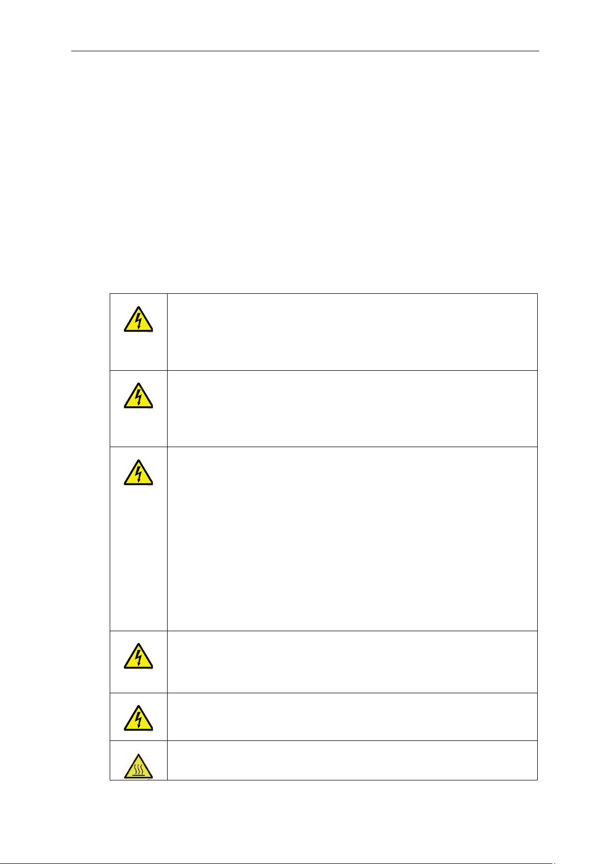
WARNING!
connected to mains. A contact with this voltage is very dangerous.
WARNING!
mains.
WARNING!
stopped.
WARNING!
work.
WARNING!
HOT SURFACE!
1 Introduction
1.1 Intended use
This is an additional guide for the usage of the VLT® Advanced Harmonic Filter (AHF)
®
with VACON
an AHF filter with a VACON
Harmonic Filter includes all technical and regulatory information which is also usable
with VACON
1.2 Safety
100 Family drives. The guide gives information on how to install and use
®
100 Family drive. The Design Guide for VLT® Advanced
®
100 Family drives, and is not replaced by this document.
Do not touch the components of the filter when the drive system is
connected to mains. The components are live when the drive system is
Do not touch the input / output terminals of the filter. They can have a
dangerous voltage also when the drive system is disconnected from
Before you do electrical work on the drive system, disconnect the drive
from the mains and make sure that the motor has stopped. Lock out
and tag out the power source to the drive system. Make sure that no
external source generates unintended voltage during work. Note that
also the load side of drive system can generate voltage.
Wait 5 minutes before you open the the cover of the filter product. Use a
measuring device to make sure that there is no voltage. The terminal
connections and the components of the filter can be live 5 minutes after
the drive system is disconnected from the mains and the motor has
Only qualified electricians are allowed to do installation and service
Do not do repair work on a defective product.
Local contacts: https://www.danfoss.com/en/contact-us/contacts-list/
Page 5
Installation vacon • 3
2
becomes hot during operation.
CAUTION!
noise and to prevent malfunction in the installation.
Do not touch the surface of the filter. The surface of the filter product
Use shielded cables to reduce noise, electromagnetic interference
1.3 Harmonic mitigation
Several mitigation methods can be found for the harmonics caused by AC drives. Most
®
commonly used are passive and active harmonic filters. The VLT
harmonic filter that consists of capacitors and inductors. The filter series offers two
performance levels:
• AHF 005 with 5% THDi
• AHF 010 with 10% THDi
AHF is a passive
1.4 Operating principle of the AHF
The operating principle of the VLT® AHF filter is described in the Design Guide for
®
Advanced Harmonic Filter.
VLT
2 Installation
2.1 Mechanical installation
Mounting requirements of the VLT® AHF filter can be found in the Design Guide for
®
Advanced Harmonic Filter.
VLT
2.2 Electrical installation
General electrical installation instructions can be found in the Design Guide for VLT®
Advanced Harmonic Filter.
Local contacts: https://www.danfoss.com/en/contact-us/contacts-list/
Page 6

4 • vacon Installation
2
Figure 1. Connection diagram with VACON® 100 Family terminals
Figure 2. Parallel use of two AHF filters with capacitor disconnection
2.3 Programming of digital inputs
Programming example for overtemperature protection in VACON® 100 Family drives is
described below.
1. Connect terminal A of the advanced harmonic filter to terminal 6 or 12 (voltage
supply digital input, 24 V) of the drive.
2. Connect terminal B to terminal 8-10 or 14-16 of the drive.
3. Program the digital input parameter AHF Over Temperature (P3.5.1.59 in
®
VACON
selected digital input terminal.
100 FLOW or P3.5.1.52 in VACON® 100 INDUSTRIAL) according to the
Local contacts: https://www.danfoss.com/en/contact-us/contacts-list/
Page 7

Selection of an AHF filter vacon • 5
3
Enclosure size, enclosure
380-500
V
VACON 01003L-0003-5
VACON 01003L-0004-5
VACON 01003L-0005-5
VACON 0100-
VACON 01003L-0009-5
VACON 01003L-0012-5
VACON 01003L-0016-5
VACON 01003L-0023-5
VACON 0100-
VACON 01003L-0038-5
VACON 01003L-0046-5
VACON 01003L-0061-5
VACON 01003L-0072-5
VACON 01003L-0087-5
VACON 01003L-0105-5
VACON 01003L-0140-5
VACON 01003L-0170-5
VACON 01003L-0205-5
VACON 01003L-0261-5
VACON 01003L-0310-5
If an overtemperature is detected, there are four options for parameter AHF fault
®
response (P3.23.4 in VACON
100 FLOW and P3.22.4 in VACON® 100 INDUSTRIAL):
0 = No Action
1 = Alarm
2 = Fault
3 = Fault, Coast
3 Selection of an AHF filter
3.1 Selection tables
AC drive values Filter values
Enclosure
size
MR4
MR5
MR6
Drive type
3L-0008-5
3L-0031-5
Power
rating
[kW] [A] [A] IP20 [W] [W] [dB] IP20
1.1 3.4 10 130B1229 130B1027 142 86 <70 X1-V3 IP20 if X1-V3 IP20 if
1.5 4.6 10 130B1229 130B1027 142 86 <70 X1-V3 IP20 if X1-V3 IP20 if
2.2 5.4 10 130B1229 130B1027 142 86 <70 X1-V3 IP20 if X1-V3 IP20 if
5.5 11.3 14 130B1231 130B1058 177 137 <70 X1-V3 IP20 ef X1-V3 IP20 ef
7.5 15.4 14 130B1231 130B1058 177 137 <70 X1-V3 IP20 ef X1-V3 IP20 ef
18.5 26.7 40 130B1239 130B1111 457 317 <72 X3-V3 IP20 if X3-V3 IP20 if
Table 1. 380 – 415 V, 50Hz
Input
current
3 8.1 10 130B1229 130B1027 142 86 <70 X1-V3 IP20 if X1-V3 IP20 if
4 9.3 10 130B1229 130B1027 142 86 <70 X1-V3 IP20 if X1-V3 IP20 if
11 21.3 22 130B1232 130B1059 286 229 <70 X2-V3 IP20 ef X2-V3 IP20 if
15 28.4 29 130B1233 130B1089 357 248 <70 X2-V3 IP20 ef X2-V3 IP20 if
22 43.6 55 130B1240 130B1176 541 387 <72 X3-V3 IP20 if X3-V3 IP20 if
Current
rating
Ordering numbers Power loss
AHF 005 AHF 010 AHF 005 AHF 010 AHF 005 AHF 010
Acoustic
noise
protection rating,
and fan concept
MR7
MR8
MR9
30 58.2 66 130B1241 130B1180 717 512 <72 X4-V3 IP20 if X4-V3 IP20 if
37 67.5 66 130B1241 130B1180 717 512 <72 X4-V3 IP20 if X4-V3 IP20 if
45 85.3 96 130B1248 130B1204 699 554 <75 X5-V3 IP20 ef X5-V3 IP20 ef
55 100.66 133 130B1249 130B1207 873 737 <75 X5-V3 IP20 ef X5-V3 IP20 ef
75 139.4 171 130B1250 130B1213 1215 895 <75 X6-V3 IP20 ef X6-V3 IP20 if
90 166.5 171 130B1250 130B1213 1215 895 <75 X6-V3 IP20 ef X6-V3 IP20 if
110 199.6 204 130B1251 130B1214 1253 905 <75 X6-V3 IP20 ef X6-V3 IP20 if
132 258 304 130B1259 130B1216 1505 1352 <75 X7-V3 IP20 if X7-V3 IP20 if
160 303 304 130B1259 130B1216 1505 1352 <75 X7-V3 IP20 if X7-V3 IP20 if
Local contacts: https://www.danfoss.com/en/contact-us/contacts-list/
Page 8

6 • vacon Selection of an AHF filter
3
Enclosure sizes, enclosure
380-500
V
VACON 01003L-0003-5
VACON 01003L-0004-5
VACON 01003L-0005-5
VACON 0100-
VACON 01003L-0009-5
VACON 01003L-0012-5
VACON 01003L-0016-5
VACON 01003L-0023-5
VACON 0100-
VACON 01003L-0038-5
VACON 01003L-0046-5
VACON 01003L-0061-5
VACON 01003L-0072-5
VACON 01003L-0087-5
VACON 01003L-0105-5
VACON 01003L-0140-5
VACON 01003L-0170-5
VACON 01003L-0205-5
VACON 01003L-0261-5
VACON 01003L-0310-5
Enclosure sizes, enclosure
and fan concept
380-500
VACON 01003L-0003-5
VACON 01003L-0004-5
VACON 01003L-0005-5
VACON 01003L-0008-5
VACON 01003L-0009-5
VACON 0100-
Table 2. 380 – 415 V, 60Hz
AC drive values Filter values
Enclosure
size
MR4
MR5
MR6
Drive type
3L-0008-5
3L-0031-5
Input
Power
rating
[kW] [A] [A] IP20 [W] [W] [dB] IP20
18.5 26.7 40 130B2862 130B2303 457 317 <72 X3-V3 IP20 if X3-V3 IP20 if
current
1.1 3.4 10 130B2857 130B2262 142 86 <70 X1-V3 IP20 if X1-V3 IP20 if
1.5 4.6 10 130B2857 130B2262 142 86 <70 X1-V3 IP20 if X1-V3 IP20 if
2.2 5.4 10 130B2857 130B2262 142 86 <70 X1-V3 IP20 if X1-V3 IP20 if
3 8.1 10 130B2857 130B2262 142 86 <70 X1-V3 IP20 if X1-V3 IP20 if
4 9.3 10 130B2857 130B2262 142 86 <70 X1-V3 IP20 if X1-V3 IP20 if
5.5 11.3 14 130B2858 130B2265 177 137 <70 X1-V3 IP20 ef X1-V3 IP20 ef
7.5 15.4 22 130B2859 130B2268 286 229 <70 X2-V3 IP20 ef X2-V3 IP20 if
11 21.3 22 130B2859 130B2268 286 229 <70 X2-V3 IP20 ef X2-V3 IP20 if
15 28.4 29 130B2860 130B2294 357 248 <70 X2-V3 IP20 ef X2-V3 IP20 if
22 43.6 55 130B2863 130B2445 541 387 <72 X3-V3 IP20 if X3-V3 IP20 if
30 58.2 66 130B2864 130B2459 717 512 <72 X4-V3 IP20 if X4-V3 IP20 if
37 67.5 82 130B2865 130B2488 733 447 <72 X4-V3 IP20 ef X4-V3 IP20 ef
Current
rating
Ordering numbers Power loss
AHF 005 AHF 010 AHF 005 AHF 010 AHF 005 AHF 010
Acoustic
noise
protection rating,
and fan concept
MR7
MR8
MR9
45 85.3 82 130B2865 130B2488 733 447 <72 X4-V3 IP20 ef X4-V3 IP20 ef
55 100.66 133 130B2867 130B2498 873 737 <75 X5-V3 IP20 ef X5-V3 IP20 ef
75 139.4 171 130B2868 130B2499 1215 895 <75 X6-V3 IP20 ef X6-V3 IP20 if
90 166.5 171 130B2868 130B2499 1215 895 <75 X6-V3 IP20 ef X6-V3 IP20 if
110 199.6 204 130B2869 130B2500 1253 905 <75 X6-V3 IP20 ef X6-V3 IP20 if
132 258 304 130B2871 130B2819 1505 1352 <75 X8-V3 IP20 if X7-V3 IP20 if
160 303 304 130B2871 130B2819 1505 1352 <75 X8-V3 IP20 if X7-V3 IP20 if
Table 3. 440 – 480 V, 60Hz
AC drive values Filter values
Enclosure
size
MR4
Drive type
Input
Power
rating
current
[kW] [A] [A] IP20 [W] [W] [dB] IP20
1.1 3.4 10 130B1752 130B1482 163 99 <70 X1-V3 IP20 if X1-V3 IP20 if
1.5 4.6 10 130B1752 130B1482 163 99 <70 X1-V3 IP20 if X1-V3 IP20 if
2.2 5.4 10 130B1752 130B1482 163 99 <70 X1-V3 IP20 if X1-V3 IP20 if
3 8.1 10 130B1752 130B1482 163 99 <70 X1-V3 IP20 if X1-V3 IP20 if
Current
rating
V
Ordering numbers Power loss
AHF 005 AHF 010 AHF 005 AHF 010 AHF 005 AHF 010
Acoustic
noise
protection rating,
3L-0012-5
4 9.3 10 130B1752 130B1482 163 99 <70 X1-V3 IP20 if X1-V3 IP20 if
5.5 11.3 14 130B1753 130B1483 206 160 <70 X1-V3 IP20 ef X1-V3 IP20 ef
Local contacts: https://www.danfoss.com/en/contact-us/contacts-list/
Page 9

Selection of an AHF filter vacon • 7
3
VACON 01003L-0016-5
VACON 01003L-0023-5
VACON 01003L-0031-5
VACON 01003L-0038-5
VACON 01003L-0046-5
VACON 01003L-0061-5
VACON 01003L-0072-5
VACON 0100-
VACON 01003L-0105-5
VACON 01003L-0140-5
VACON 01003L-0170-5
VACON 01003L-0205-5
VACON 0100-
VACON 01003L-0310-5
VACON 01003L-0004-6
VACON 01003L-0006-6
VACON 0100-
VACON 01003L-0011-6
VACON 01003L-0018-6
VACON 01003L-0022-6
VACON 01003L-0027-6
VACON 0100-
VACON 01003L-0041-6
VACON 01003L-0052-6
VACON 01003L-0062-6
VACON 01003L-0080-6
VACON 01003L-0100-6
VACON 01003L-0125-6
VACON 01003L-0144-6
VACON 01003L-0208-6
7.5 15.4 25 130B1755 130B1485 354 245 <70 X2-V3 IP20 ef X2-V3 IP20 if
MR5
MR6
MR7
MR8
MR9
3L-0087-5
3L-0261-5
11 21.3 25 130B1755 130B1485 354 245 <70 X2-V3 IP20 ef X2-V3 IP20 if
15 28.4 31 130B1756 130B1486 448 301 <70 X3-V3 IP20 if X3-V3 IP20 if
18.5 26.7 36 130B1757 130B1487 474 329 <72 X3-V3 IP20 if X3-V3 IP20 if
22 43.6 48 130B1758 130B1488 543 389 <72 X3-V3 IP20 if X3-V3 IP20 if
30 58.2 60 130B1759 130B1491 751 537 <72 X4-V3 IP20 if X4-V3 IP20 if
37 67.5 73 130B1760 130B1492 751 458 <72 X4-V3 IP20 ef X4-V3 IP20 ef
45 85.3 95 130B1761 130B1493 801 635 <75 X5-V3 IP20 ef X5-V3 IP20 ef
55 100.66 118 130B1762 130B1494 891 753 <75 X5-V3 IP20 ef X5-V3 IP20 ef
75 139.4 154 130B1763 130B1495 1260 928 <75 X6-V3 IP20 ef X6-V3 IP20 if
90 166.5 183 130B1764 130B1496 1293 935 <75 X6-V3 IP20 ef X6-V3 IP20 if
110 199.6 231 130B1765 130B1497 1450 1267 <75 X7-V3 IP20 if X7-V3 IP20 if
132 258 291 130B1766 130B1498 1664 1496 <75 X8-V3 IP20 if X7-V3 IP20 if
160 303 355 130B1768 130B1499 2098 1758 <75 X8-V3 IP20 ef X7-V3 IP20 ef
Table 4. 525 – 600 V, 60Hz
Enclosure
size
MR5
MR6
MR7
Drive type
3L-0009-6
3L-0034-6
AC drive values Filter values
Power
rating
[Hp] [A] [A] IP20 [W] [W] [dB] IP20
7.5 9 15 130B5246 130B5212 301 245 <70 X3-V3 IP20 if X3-V3 IP20 if
10 10.5 15 130B5246 130B5212 301 245 <70 X3-V3 IP20 if X3-V3 IP20 if
15 19.9 20 130B5247 130B5213 388 276 <70 X3-V3 IP20 if X3-V3 IP20 if
20 23.3 24 130B5248 130B5214 428 315 <70 X3-V3 IP20 ef X3-V3 IP20 ef
25 27.2 29 130B5249 130B5215 450 331 <70 X4-V3 IP20 ef X4-V3 IP20 ef
30 32.8 36 130B5250 130B5216 611 445 <70 X4-V3 IP20 ef X4-V3 IP20 ef
40 45.3 50 130B5251 130B5217 642 454 <70 X5-V3 IP20 ef X5-V3 IP20 ef
50 53.8 58 130B5252 130B5218 691 531 <70 X5-V3 IP20 ef X5-V3 IP20 ef
60 62.2 77 130B5253 130B5219 870 669 <72 X6-V3 IP20 ef X6-V3 IP20 ef
75 90 87 130B5254 130B5220 1001 770 <72 X6-V3 IP20 ef X6-V3 IP20 ef
Input
current
600 V AHF 005 AHF 010 AHF 005 AHF 010 AHF 005 AHF 010
3 4.6 15 130B5246 130B5212 301 245 <70 X3-V3 IP20 if X3-V3 IP20 if
5 6.8 15 130B5246 130B5212 301 245 <70 X3-V3 IP20 if X3-V3 IP20 if
Current
rating
Ordering numbers Power loss
Acoustic
noise
Enclosure sizes, enclosure
protection rating, and fan concept
MR8
MR9
100 106 109 130B5255 130B5221 1038 798 <72 X6-V3 IP20 ef X6-V3 IP20 ef
125 127 128 130B5256 130B5222 1091 909 <75 X6-V3 IP20 ef X6-V3 IP20 ef
150 156 155 130B5257 130B5223 1397 1164 <75 X7-V3 IP20 ef X7-V3 IP20 ef
200 212 240 130B5259 130B5225 1831 1591 <75 X8-V3 IP20 ef X7-V3 IP20 ef
Local contacts: https://www.danfoss.com/en/contact-us/contacts-list/
Page 10

8 • vacon Selection of an AHF filter
3
Enclosure sizes, enclosure
and fan concept
525-690
V
AHF
005
AHF
010
VACON 0100-
VACON 01003L-0010-7
VACON 01003L-0013-7
VACON 01003L-0018-7
VACON 01003L-0022-7
VACON 01003L-0027-7
VACON 01003L-0034-7
VACON 01003L-0041-7
VACON 01003L-0052-7
VACON 01003L-0062-7
VACON 0100-
VACON 01003L-0100-7
VACON 01003L-0125-7
VACON 01003L-0144-7
VACON 01003L-0170-7
VACON 01003L-0208-7
AC drive values Filter values
Table 5. 525 – 690 V, 50Hz
Enclosure
size
MR6
MR7
MR8
Drive type
3L-0007-7
3L-0080-7
Input
Power
rating
current
[kW] [A] [A] [A] IP20 [W] [W] [dB] IP20
5.5 9.1 15 15 130B5088 130B5280 347 282 <70 X3-V3 IP20 if X3-V3 IP20 if
7.5 11.7 15 15 130B5088 130B5280 347 282 <70 X3-V3 IP20 if X3-V3 IP20 if
11 15.5 15 15 130B5088 130B5280 347 282 <70 X3-V3 IP20 if X3-V3 IP20 if
15 19.9 20 20 130B5089 130B5281 446 318 <70 X3-V3 IP20 if X3-V3 IP20 if
18.5 23.3 24 24 130B5090 130B5282 493 362 <70 X3-V3 IP20 ef X3-V3 IP20 ef
22 27.2 29 29 130B5092 130B5283 518 381 <70 X4-V3 IP20 ef X4-V3 IP20 ef
30 32.8 36 36 130B5125 130B5284 703 512 <70 X4-V3 IP20 ef X4-V3 IP20 ef
37 45.3 50 50 130B5144 130B5285 718 522 <70 X5-V3 IP20 ef X5-V3 IP20 ef
45 53.8 58 58 130B5168 130B5286 795 611 <72 X5-V3 IP20 ef X5-V3 IP20 ef
55 62.2 77 77 130B5169 130B5287 1001 770 <72 X6-V3 IP20 ef X6-V3 IP20 ef
75 90 87 87 130B5170 130B5288 1152 886 <72 X6-V3 IP20 ef X6-V3 IP20 ef
90 106 109 109 130B5172 130B5289 1194 918 <72 X6-V3 IP20 ef X6-V3 IP20 ef
110 127 128 128 130B5195 130B5290 1255 1046 <72 X6-V3 IP20 ef X6-V3 IP20 ef
Current rating Ordering numbers Power loss
AHF 005 AHF 010 AHF 005 AHF 010
Acoustic
noise
protection rating,
AHF 005 AHF 010
MR9
132 156 155 155 130B5196 130B5291 1607 1339 <72 X7-V3 IP20 ef X7-V3 IP20 ef
160 179 197 197 130B5197 130B5292 1734 1515 <72 X7-V3 IP20 ef X7-V3 IP20 ef
200 212 240 240 130B5198 130B5293 2106 1830 <75 X8-V3 IP20 ef X7-V3 IP20 ef
Local contacts: https://www.danfoss.com/en/contact-us/contacts-list/
Page 11

Programming vacon • 9
4
3.2 Contactors for capacitor disconnection (option)
The power factor of the VLT® AHF filter decreases with a decreasing load. When there
is no load, the power factor is 0, and the capacitors produce a leading current of
approximately 25% of the rated filter current. In applications where reactive current
is not acceptable, the disconnection of capacitors is required.
The AHF filter terminals X3.1, X3.2, X3.3 and X4.1, X4.2, X4.3 are shorted as default. If
disconnection of capacitors is required, the shorting is removed and a 3-phase
contactor is placed between terminals X3 and X4.
NOTE! During the download of a VACON® 100 software, it is recommended to short
the AHF filter terminals X3.1, X3.2, X3.3 and X4.1, X4.2, X4.3 to avoid unnecessary
capacitor disconnections.
NOTE! It is recommended to use contactors designed for capacitive switching with
®
VACON
the inrush peak current and peak voltage level in the DC bus of the drive.
100 Family drives. These contactors include damping resistors that reduce
In some cases, the DC bus peak voltage can reach the hardware trip level with
standard AC-3 type contactors and cause the drive to shut down. This can happen
during disconnection or connection of the filter capacitors at low load. It is possible to
control the disconnection of capacitors with parameter settings (see chapter
Programming).
3.3 Accessories
Available upgrade kits are listed in the Design Guide for VLT® Advanced Harmonic
Filter. Available kits for the VACON
• IP21 / NEMA 1 Upgrade Kit
• Backplate for IP20 (to correct the air flow in a rail assembly).
4 Programming
4.1 Parameter settings
The parameters related to the VLT® AHF filter (VACON® 100 FLOW / VACON® 100
INDUSTRIAL):
®
100 Family drives:
P3.23.1 / P3.22.1 Cap Disconnect Limit
P3.23.2 / P3.22.2 Cap Disconnect Hysteresis
P3.23.3 / P3.22.3 AHF Over Temperature
P3.23.4 / P3.22.4 AHF Response
The settings of these parameters are described in the VACON
Manual and the VACON
Local contacts: https://www.danfoss.com/en/contact-us/contacts-list/
®
100 INDUSTRIAL Application Manual.
®
100 FLOW Application
Page 12

10 • vacon Technical data
5
NOTE! The default setting for parameter P3.23.1 / P3.22.1 is 0% with the capacitor
disconnection not in use. If the capacitor disconnection is activated, the value of
parameter P3.23.1 / P3.22.1 must be set between 10-30%.
4.2 Digital inputs
Program the digital input parameter AHF Over Temperature (P3.5.1.59 in VACON® 100
®
FLOW and P3.5.1.52 in VACON
100 INDUSTRIAL) according to the selected input
terminal.
®
VACON
100 FLOW :
P3.5.1.59 AHF Over Temperature (ID 15513): default value = DigIN Slot0.1
®
VACON
100 INDUSTRIAL:
P3.5.1.52 AHF Over Temperature (ID 15513): default value = DigIN Slot0.1
4.3 Digital outputs
Program the digital output parameter RO1 Function (P3.5.3.2.1) according the
capacitor disconnection selection.
®
VACON
100 FLOW:
P3.5.3.2.1 RO1 Function (ID 11001): value 72 = AHF Cap Disconnect, value 73 = AHF
Cap Disconnect Inverted
®
VACON
100 INDUSTRIAL:
P3.5.3.2.1 RO1 Function (ID 11001): value 60 = AHF Cap Disconnect, value 61 = AHF
Cap Disconnect Inverted
5 Technical data
The techincal data including mechanical dimensions can be found in the Design Guide
®
for VLT
Advanced Harmonic Filter.
Local contacts: https://www.danfoss.com/en/contact-us/contacts-list/
Page 13

Page 14

www.danfoss.com
Vacon Ltd
Member of the Danfoss Group
Runsorintie 7
65380 Vaasa
Finland
130R0809
*M0024001*
 Loading...