

Page 1
Technical Information
Tips on Hydraulics
www.danfoss.com
Page 2

Technical Information
Tips on Hydraulics
Revision history Table of revisions
Date Changed Rev
October 2019 1994 version scanned, then recreated 0101
2 | © Danfoss | October 2019 BC317769130475en-000101
Page 3

Technical Information
Tips on Hydraulics
Contents
Introduction
Dimensioning
Selection of components
Selection of oil type
Checking the oil
Installation of system
Starting up and running-in
Maintenance
Fault location
Repair and testing
Size of pump.......................................................................................................................................................................................6
Sizes of pipes and hoses.................................................................................................................................................................6
Using the nomogram......................................................................................................................................................................7
Valves....................................................................................................................................................................................................7
Calculating on the tube diameter.............................................................................................................................................. 8
Calculation of piston velocity - oil flow.................................................................................................................................... 9
Calculation of cylinder force...................................................................................................................................................... 10
Table of cylinder power...............................................................................................................................................................11
The tank.............................................................................................................................................................................................12
Filters.................................................................................................................................................................................................. 13
Relative size of particles...............................................................................................................................................................14
Dimensions.......................................................................................................................................................................................15
Oil requirements.............................................................................................................................................................................16
Types of hydraulic-liquids...........................................................................................................................................................16
Oil types.............................................................................................................................................................................................16
Non-inflammable fluids...............................................................................................................................................................16
Additives........................................................................................................................................................................................... 16
Motor oil............................................................................................................................................................................................17
Viscosity classification system...................................................................................................................................................18
Water in the oil................................................................................................................................................................................19
Oil oxidation.....................................................................................................................................................................................19
The presence of water..................................................................................................................................................................19
Viscosity.............................................................................................................................................................................................19
The smell and appearance..........................................................................................................................................................19
Tables for conversing viscosity................................................................................................................................................. 20
Hydraulic oil temperature conditions oil life in %..............................................................................................................21
Rule 1..................................................................................................................................................................................................22
Fine filtration of the oil via a filling filter unit................................................................................................................. 23
Rule 2..................................................................................................................................................................................................24
Rule 3..................................................................................................................................................................................................24
Procedure for starting up............................................................................................................................................................25
Periodic inspection........................................................................................................................................................................27
The tank.............................................................................................................................................................................................27
The suction line...............................................................................................................................................................................27
The pump..........................................................................................................................................................................................27
The return line and return filter................................................................................................................................................ 27
Pump test..........................................................................................................................................................................................28
Fault location general...................................................................................................................................................................29
Hydraulic pumps............................................................................................................................................................................29
Hydraulic motors............................................................................................................................................................................30
Steering systems with OSPB - OSPC - OVP/OVR - OLS......................................................................................................31
Steering units OSPB - OSPC - OVP/OVR - OLS.................................................................................................................32
Steering systems with OSQA/B and OSPBX-LS....................................................................................................................34
Faults locations illustrations.......................................................................................................................................................35
©
Danfoss | October 2019 BC317769130475en-000101 | 3
Page 4

Technical Information
Tips on Hydraulics
Contents
Repair..................................................................................................................................................................................................36
Testing................................................................................................................................................................................................36
Symbols and Tables
Symbols............................................................................................................................................................................................. 37
Ratio factors..................................................................................................................................................................................... 37
Pump.................................................................................................................................................................................................. 38
Motor..................................................................................................................................................................................................38
Cylinder..............................................................................................................................................................................................39
Tube....................................................................................................................................................................................................39
Accumulator size............................................................................................................................................................................39
ISO/CETOP Symbols
Catalogues or leaflets available
Hydraulic components leaflets or catalogues.....................................................................................................................44
Service shops...................................................................................................................................................................................44
4 | © Danfoss | October 2019 BC317769130475en-000101
Page 5

Technical Information
Tips on Hydraulics
Introduction
Like so many other technical fields, hydraulics is both old and new at the same time.
Take waterwheels for example, people have been using them since before history was recorded. On the
other hand, the use of liquid under pressure to transfer force and also to control complicated movements
is relatively new and has undergone its most rapid development within the last 40-50 years, not least
because of the work that has been done in aeronautics.
Hydraulics and pneumatics are universal for the entire engineering industry and are amongst the three
most important media for the transference and control of force. The two other media are mechanical
transference for example via clutch pedals and gears) and electrical (for example via a generator).
"Flowing energy" is transferred and controlled through a medium under pressure - either air (pneumatic)
or liquid (hydraulic).
This form of energy has many exceptional advantages and is therefore often the most suitable form of
energy transference on land, sea or in the air.
A contained liquid is one of the most versatile means of controlling and transferring force. It takes the
precise form of the walls that contain it and withstands its pressure. It can be divided into several streams
which, depending on their size, can perform work before being allowed to merge into one stream again
to perform still more work. It can be made to work fast in one part of a system and slowly in another.
No other medium combines the same degree of reliability, accuracy and flexibility while retaining the
capability of transferring maximum force with minimum volume and weight. The quality control with this
medium can be compared with the accuracy of an electronic micro-processor.
However, to achieve maximum utilization with highest efficiency and least possible operational stops, it
is very important that a hydraulic system be designed, manufactured, started and maintained absolutely
correctly. The special factors vital to the user (purchaser) must also be understood if operation in the field
is not to be plagued by stops and other disturbances.
Nearly all factory systems use "flowing energy" in production. More than half of all manufactured
products are based on this form of energy, and it is therefore of interest to all manufacturers, exporters,
purchasers, stockists, and repairers of production systems and machines, including agricultural machines
and machine pools, the village smithy and the automobile industry, shipping and aviation.
Clearly, the knowledge and experience of many designers, producers, repairers and owners (users) is
being outstripped by the dramatic development and rapid spread of hydraulics.
The purpose of this article is therefore not to try to provide patent solutions to all hydraulic problems, but
to help create an understanding of why problems arise and what steps can be taken to avoid them.
©
Danfoss | October 2019 BC317769130475en-000101 | 5
Page 6
Technical Information
Tips on Hydraulics
Dimensioning
Reliable sizing provides the most optimal selection of components.
It is obvious that if undersized components are used, they will not operate under overload. They will be
sensitive and become a frequent source of problems and complaints. More important still, in comparison
with a correctly sized component an oversize component will probably operate problem-free and
"effortlessly " for a very long time, but its original price will be too high.
If not able to carry out accurate calculations to obtain optimum conditions, the guidelines below are
worth following.
The first thing to establish is the maximum operating pressure required for the system since this is the
decisive factor in pump selection and, in turn, important as far as the size (output) of the prime mover
and the system price are concerned. The higher the operation pressure, the higher the price of many of
the components.
When the economic considerations have been made, particular types and sizes of operating cylinders,
motors, and steering units to be used in the system can be considered.
The pump size is found by adding the necessary amounts of oil (expressed in liters per minute) that can
be in use at the same time.
Consequently, the total is the amount the pump must be able to supply at the maximum intermittent
operating pressure (= pressure relief valve setting pressure).
Size of pump
The power applied to the pump must be found as a function of the pressure in bar, revolutions per
minute and flow in liters per minute, expressed in kW. The result can be used to find the size of motor
that will safely yield the necessary output. See the following example.
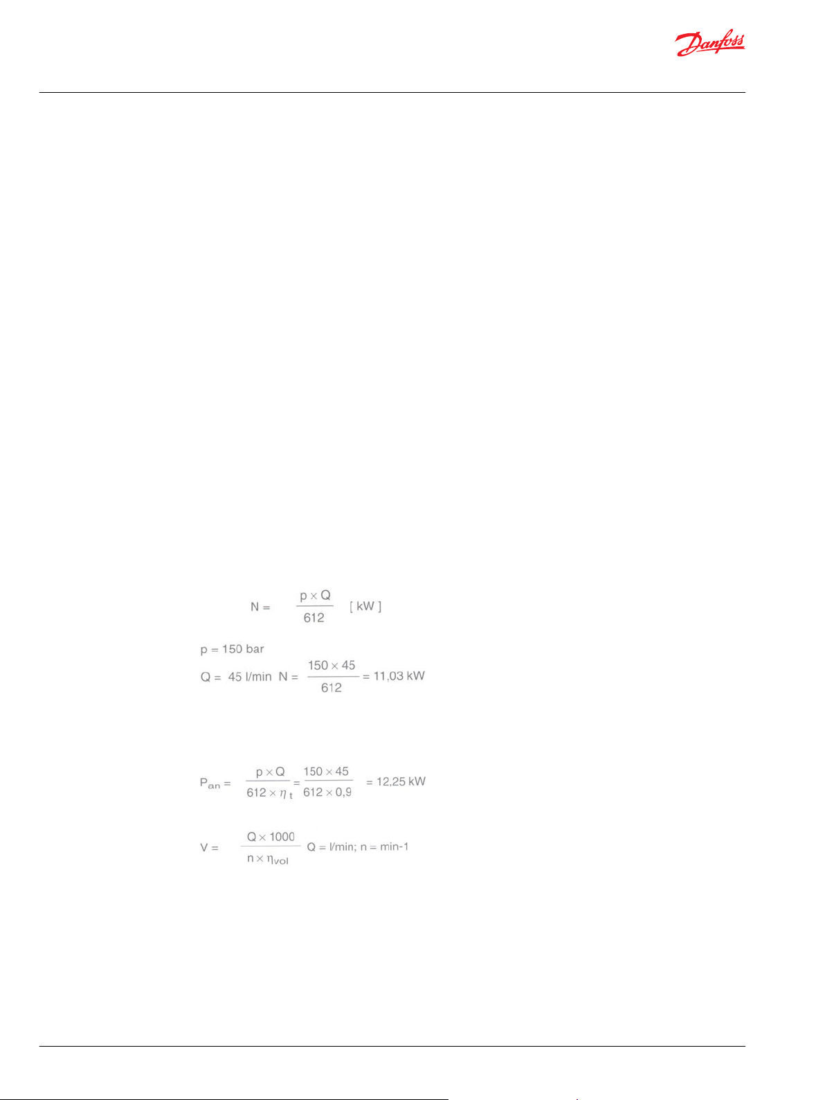
Hydraulic output N = pressure x flow, i.e. N = px Q
Example:
When calculating the necessary pump output (Pnec), account must be taken of the total pump efficiency,
(ղtot.) as stated in the catalog.
Example:
Sizes of pipes and hoses
The size depends on:
•
maximum system pressure
•
maximum oil flow
•
length of pipe system
•
environmental conditions
Pressure drop must be as small as possible. The greater the resistance in the system, the greater the
operational loss. It is important to avoid those factors which cause pressure drop such as, for example,
6 | © Danfoss | October 2019 BC317769130475en-000101
Page 7

Technical Information
Tips on Hydraulics
Dimensioning
the use of angled screwed connections. Where possible, these should be replaced by elbows. If long
lengths of pipe or high flow velocity are involved, then an increase in diameter up to the next size should
be considered.
Remember that the dimensions stated for the hydraulic pipes are the external diameters and wall
thicknesses. The internal diameters are equal to the external diameters minus 2x the wall thickness.
Remember that when the internal diameter is doubled the flow area of the pipe is quadrupled,
Now the oil capacity supplied per minute by the pump is known, along with the amount of oil the
individual components must have. The next stage is the dimensioning of pipes and hoses. This is also
very important as otherwise, generated cavitation (noise), heat generation, pressure drop and, in some
cases, bursting can occur.
There are many people who are frightened of this dimensioning as they associate it, incorrectly, with
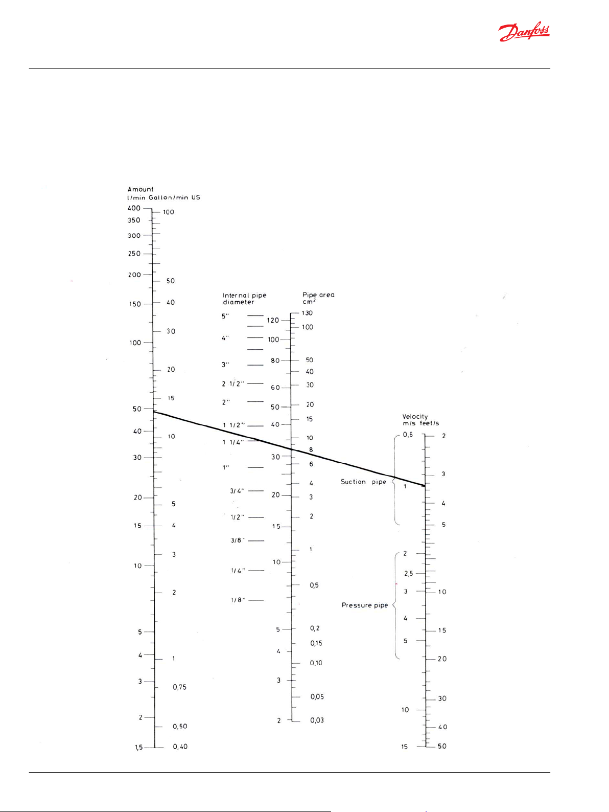
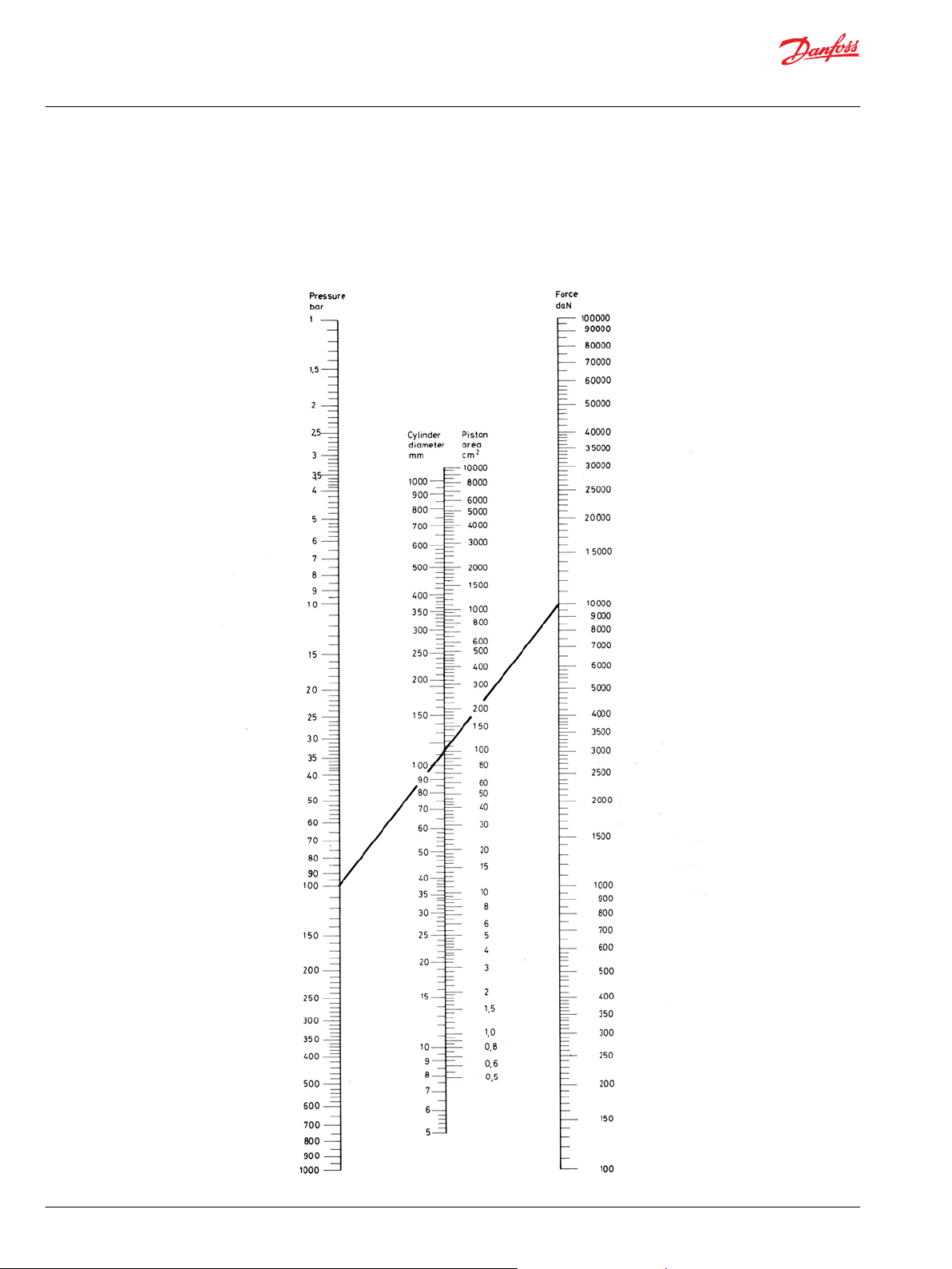
difficult mathematical calculations. In actual fact, if the nomogram adjacent is followed when calculating
pipe dimensions, it is incredibly simple.
In order to use the nomogram, the first stage is to know the oil flow in liters per minute. After this it has to
be known whether the pipes and hoses in question are to be used as suction lines, pressure lines or
return lines. This is because there are some recommended velocities of oil flow available for these
categories. These values are as follows:
•
Suction line 0.5 - 1.5 m/s
•
Pressure line 3 - 10 m/s
•
Return line 2 - 5 m/s
Using the nomogram
Valves
Place a ruler over the two outer columns, that is, the known oil flow and the required speed for the pipe
type in question. Read off the nearest internal pipe diameter on the middle column. (See Calculating on
the tube diameter on page 8.)
Depending on the maximum pressure a decision can also be made as to whether to use light or heavy
hydraulic pipes and hoses. Here a large price difference is involved, especially with the associated fittings.
See table of pipe dimensions and maximum working pressure.
Valves are used in all hydraulic systems. In simple systems maybe only a pressure relief valve (safety
valve) and a single directional valve is used. Other systems might be more complicated and might involve
a large number and wide variety of electronically controlled proportional valves.
It is probably within valves that the choice of components is widest and where it is easy to use and waste
most money if wrong selections are made.
If in doubt, the suppliers of recognized makes of valves can be approached for advice on the selection. It
is important not to select a valve which is too small or too large in relation to flow. If it is too small, the
relative pressure drop will be too high, resulting in heat generation and possibly cavitation. If the valve is
too large it can result in poor regulating characteristics causing the cylinder to not operate smoothly or
the system to oscillate.
©
Danfoss | October 2019 BC317769130475en-000101 | 7
Page 8
Technical Information
Tips on Hydraulics
Dimensioning
Calculating on the tube diameter
Example:
•
•
•
Given volume = 50 I/min
Given speed = 1 m/s
Found diameter = 32 mm
8 | © Danfoss | October 2019 BC317769130475en-000101
Page 9
Technical Information
Tips on Hydraulics
Dimensioning
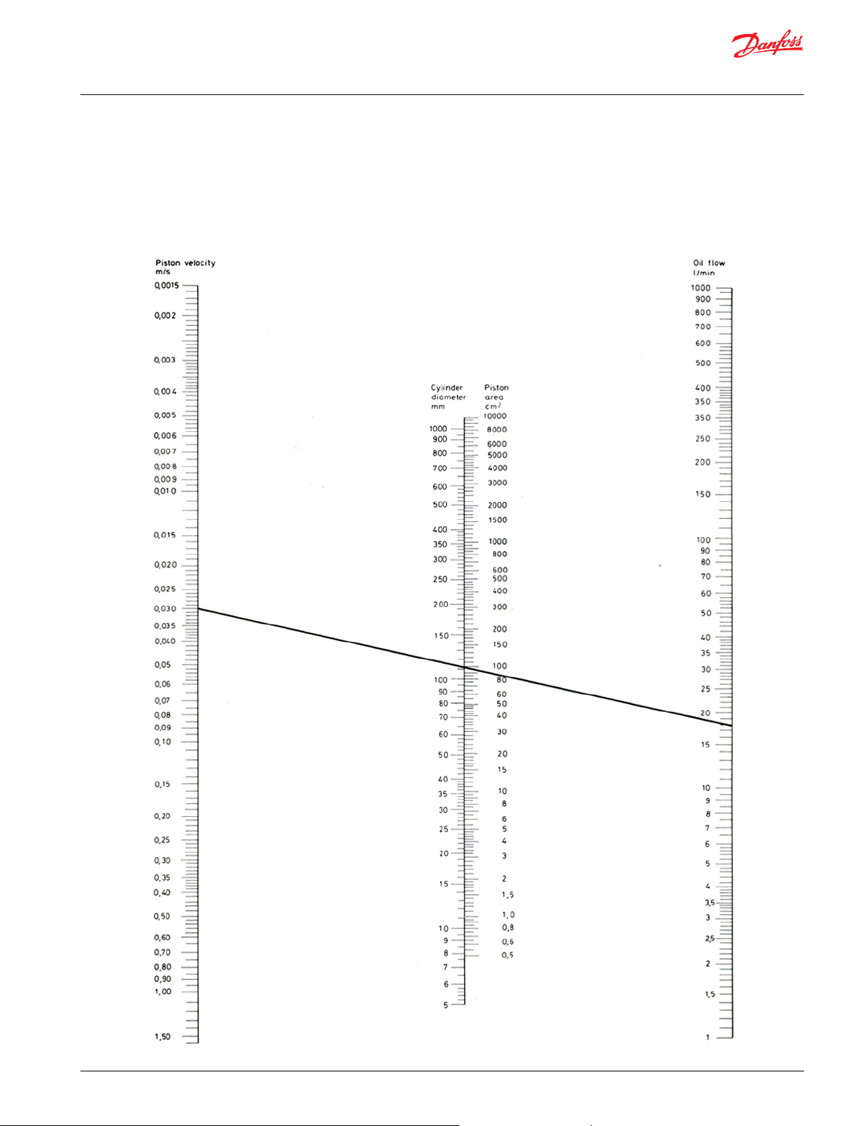
Calculation of piston velocity - oil flow
Example:
•
Given piston velocity = 0,03m/s
•
Given cylinder diameter = 112 mm
•
Found pump capacity = 18 l/min
©
Danfoss | October 2019 BC317769130475en-000101 | 9
Page 10
Technical Information
Tips on Hydraulics
Dimensioning
Calculation of cylinder force
Example:
•
Given pressure = 100 bar
•
Given cylinder diameter = 112 mm
•
Found force = 10.000 daN
10 | © Danfoss | October 2019 BC317769130475en-000101
Page 11
Technical Information
Tips on Hydraulics
Dimensioning
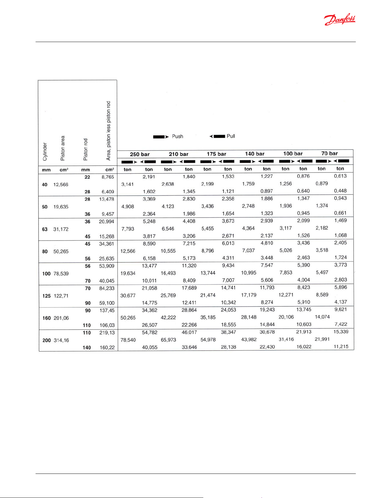
Table of cylinder power
©
Danfoss | October 2019 BC317769130475en-000101 | 11
Page 12

Technical Information
Tips on Hydraulics
Selection of components
All hydraulic systems consist in principle of the same basic components, but just as with electronics, the
combinations are infinite and the range of components immense.
Which components are the most important in a system? Is it the:
•
cylinder or the motor that is going to perform the work?
•
liquid (oil) that transfers force to the motor or cylinder?
•
pipes and hoses that lead oil to motor and cylinder?
•
valves that control the oil flow paths?
•
pump that applies energy and movement to the oil?
•
motor that drives the pump?
•
filter that removes dirt from the oil?
•
oil cooler that ensures a suitable oil temperature?
•
tank that contains oil for the system?
The answer must be that specific demands are made on all these components and since none of them
can be allowed to fail, they must all be equally important. Therefore extreme care must be taken in all
stages of their creation, selection and application.
When a hydraulic diagram is being prepared, the designer must have quality in mind, including the
quality of the drawing itself, so that any errors in interpreting the drawing are avoided. It is a good idea
always to use the correct ISO/CETOP-symbols.
When the diagram is subsequently used in preparing parts lists and accurate component specifications,
sizing problems often occur. The designer is confronted with brightly colored brochures and catalogs
and, at first, all is confusion. The temptation is to revert to rule-of-thumb methods and "add a bit for
safety's sake", the result being a system which is either too expensive or is unstable and of poor quality.
All reputable hydraulic component manufacturers give real, usable values in their catalogs, not just
theoretical desired values. The technical data in Danfoss catalogs always represent average values
measured from a certain number of standard components. In addition to these data, the catalogs contain
a mass of useful and explanatory information on selection, installation and starting up of components,
together with a description of their functions. This information must, of course, be used as intended in
order to avoid overload, too high a wear rate, and con sequent oil overheating and to avoid an overdimensioned system with poor regulation at too high a price.
The tank
Let us look a little closer at an example system, starting with:
The tank, which has many functions, for example:
•
as a reservoir for the system oil
•
as a cooler
•
as a "coarse strainer", sedimentation of impurities
•
as an air and water separator
•
as a foundation for pumps etc.
The dimensions of the tank and its form are important and it should therefore be designed for its
purpose, the same as all other hydraulic components. Its location must also be taken into account so that
the sight glass, filters, filling cap, air filter, drain cock, etc. are easily accessible for daily inspection. If the
application is mobile, if there is no cooler built into the system, and provided the tank is located where air
circulation is good, the size of the tank can be fixed at approx. 3-4 times the capacity of the pump per
minute.
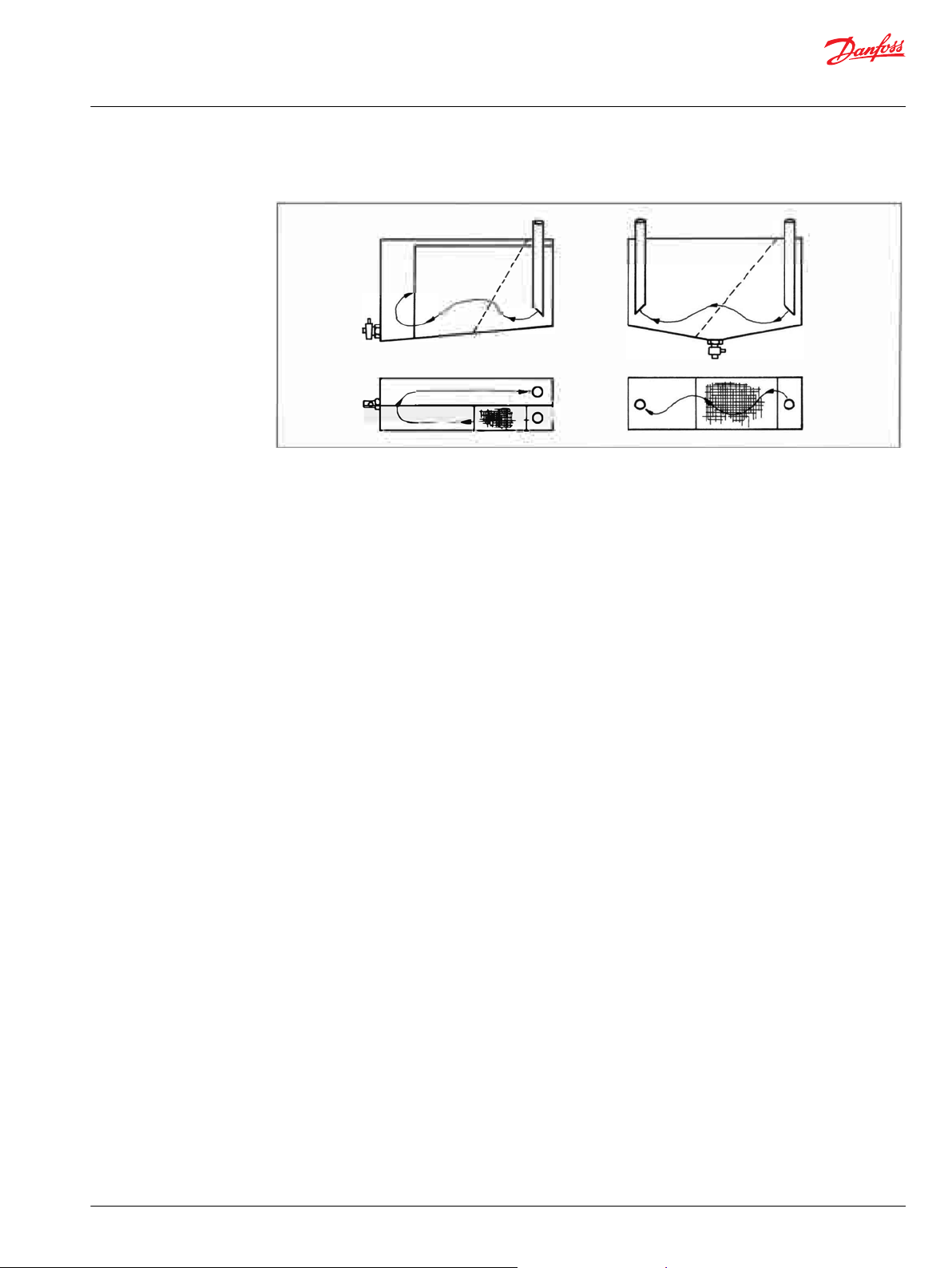
Two arrangements are shown below. The arrangement to the left, is preferred as this increases the
cooling effect as much as possible.
12 | © Danfoss | October 2019 BC317769130475en-000101
Page 13
Technical Information
Tips on Hydraulics
Selection of components
The tank functioning as a cooler - two arrangements
To increase the ability of the tank to separate dirt and water, the bottom must be slightly inclined
(deepest end opposite the inlet/outlet end). An ordinary cock (without handle) is fitted so that impurities
can easily be drained off. Increased separation of the air that is always present in the oil can be obtained
by fitting an inclined coarse metal strainer (approx. 25-50 mesh/inch) by the return line.
Both suction and return pipes must be cut diagonally. The ends of the pipes must be located 2-4 times
the pipe diameter above the bottom of the tank, partly to avoid foaming at the return line, and partly to
prevent air from being drawn into the suction line, especially when the vehicle/vessel heels over to one
side. With regard to the annual "spring-clean", the tank must have large removable covers, either in the
sides, in the top, or in the ends, in order to give easy access for cleaning. If filters are installed, they must
be located above the tank oil level and must be easy to replace without significant spillage. That is to say,
it must be possible to place a drip tray under the filter inserts.
Since tanks are made of steel plate, rust is inevitable (even below the oil level, because oil contains both
water and oxygen) and it is therefore advisable to surface-treat the inside. If the tank is to be painted,
thorough cleaning and degreasing is necessary before primer and top coats are applied. The paint used
must, of course, be resistant to hot hydraulic oil.
If the cooling effect from the tank and other hydraulic components is insufficient in order to keep oil
temperature down to an acceptable maximum an oil cooler must be fitted. Most suppliers prescribe 90°C
as an absolute maximum partly because of lifetime of rubber parts partly because of alterations of
tolerances and possibly bad lubrication. Today quite often electronic devices are fitted directly onto the
hot hydraulic components. In consideration of the electronics a reduction of the maximum oil
temperature to under 80°C must be aimed at.
Filters
The degree of filtering and filter size are based on so many different criteria, that generalization is seldom
possible. The most important factors to be considered are as follows:
Operational environment: How serious would the consequences be if the system failed because of dirt?
Oil quantity: Would there be a few liters or several hundred liters in the system? Is it an expensive or a
cheap oil?
Operational stop: What would it cost per hour/day if the system came to a standstill? How important is
this factor?
Dirt sensitivity: How dirt-sensitive are the components? What degree of filtering is recommended by the
component suppliers?
Filter types: Are suction filters, pressure filters or return filters to be used, or a combination of these with or
without magnets? Is exclusive full-flow filtering involved, or will there also be bypass filtering through
fine filters? Which type of dirt indicators are to be chosen, visual, mechanical or electrical?
Air filtration: Air must be filtered to the same degree as the finest filter in the system. Otherwise too much
dirt can enter the tank with the air. If there are large differential or plunger cylinders in the system, the
©
Danfoss | October 2019 BC317769130475en-000101 | 13
Page 14
Technical Information
Tips on Hydraulics
Selection of components
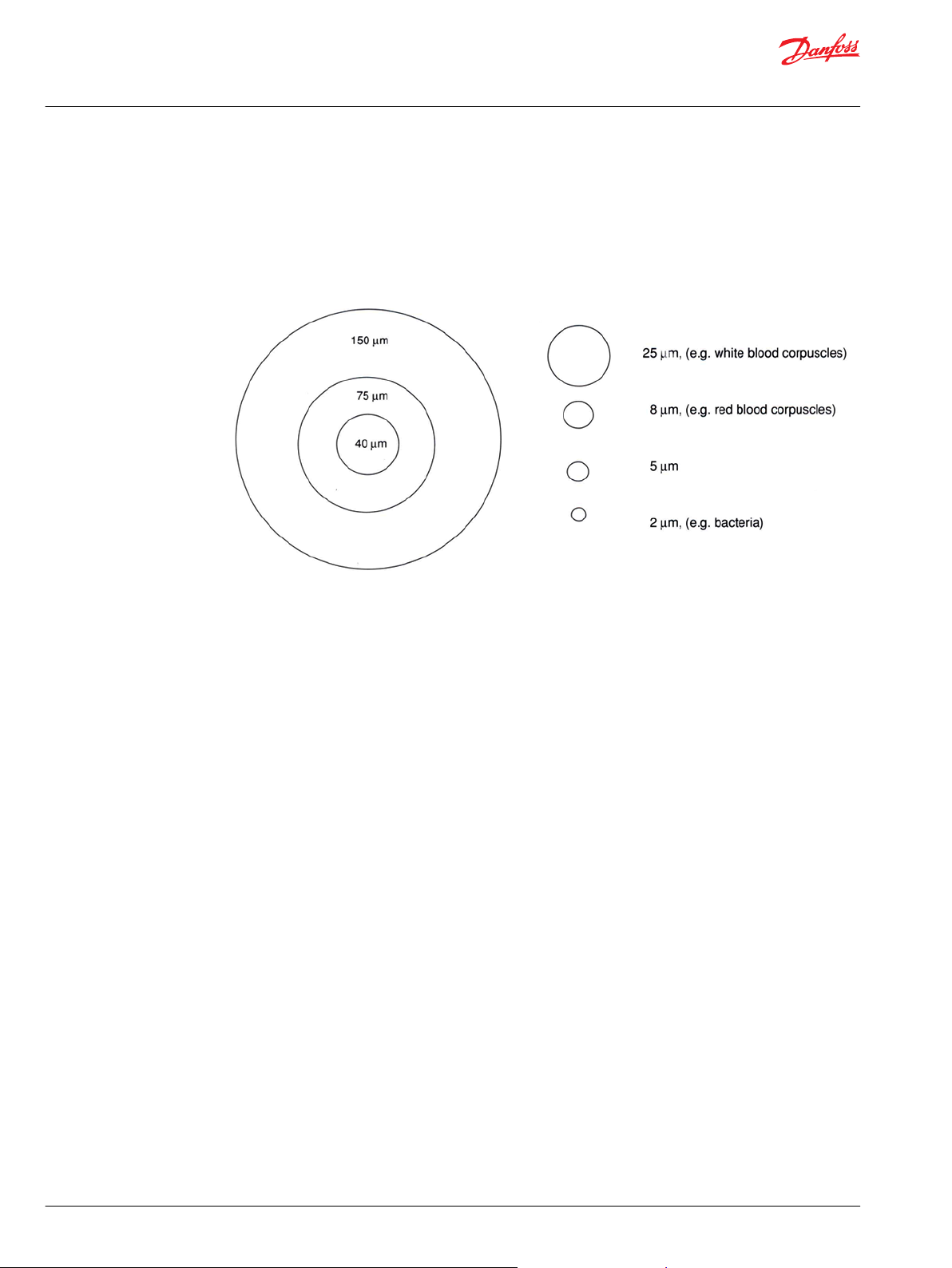
Relative size of particles
tank breathes in/pushes out large amounts of air. Therefore the size of the air filter must be on the large
side. Remember that dirt particles visible to the naked eye (larger than 40 µm) are as a rule, less
dangerous than those that cannot be seen. It is often the hard particles of 5-25 µm, corresponding to
normal hydraulic component tolerances, that are the most dangerous.
The naked eye is unable to see objects smaller than 40 µm.
For normal operation the degree of filtration for hydraulic products can generally be divided into the
categories below:
Motors: 25, µm nominal - degree of contamination 20/16 (see ISO 4406) for return filter, or combined with
a magnetic insert if a coarser filter is used, e.g. 40 µm.
Steering units: For systems having an efficient air filter and operating in clean surroundings, 25 µm
nominal is adequate. If this is not the case 10 µm absolute - to 19/16 must be fitted Filters can be either
pressure or return filters.
Proportional valves: In most cases, 25 µm nominal for return filter is adequate, but in systems especially
subjected to contamination, a pressure filter is recommended to ensure operational reliability.
Radial piston pumps: In open as well as closed systems:
Suction filter: 100 µm nominal or finer, but not finer than 40 µm nominal.
Return filter: 20 µm absolute or 10 µm nominal - 19/16.
Filters should be fitted with a dirt indicator so that operating conditions can be kept under observation.
This is especially important with suction filters to avoid impermissible pressure drop in the suction line
and consequent cavitation. The pressure in the suction line must not be less than 0.8 bar absolute.
14 | © Danfoss | October 2019 BC317769130475en-000101
Page 15

Technical Information
Tips on Hydraulics
Selection of components
Dimensions
Remember that drain lines from valves, motors etc. must also be led through the return filter to the tank.
For pumps the drain oil pressure must not exceed 1 bar. Therefore the drain oil should bypass the filters.
©
Danfoss | October 2019 BC317769130475en-000101 | 15
Page 16

Technical Information
Tips on Hydraulics
Selection of oil type
Oil requirements
Types of hydraulic-liquids
The oil in a hydraulic system must first and foremost transfer energy, but the moving parts in
components must also be lubricated to reduce friction and consequent heat generation. Additionally the
oil must lead dirt particles and friction heat away from the system and protect against corrosion.
Oil requirements:
•
good lubricating properties
•
good wear properties
•
suitable viscosity
•
good corrosion inhibitor
•
good anti-aeration properties
•
reliable air separation
•
good water separation
•
Mineral oil
•
Water
•
Oil/water-emulsions
•
Water/polyglycol mixture
•
Synthetic liquids
Oil types
Non-inflammable fluids
The most common hydraulic oil is a mineral based oil.
CETOP RP75H-class comprises following 4 groups:
•
HH: oil without additives
•
HL: oil with special additives for improving aging-durability and protecting against corrosion
•
HM: "HL" + additives for improving wear-properties
•
HV: "HM" + additives for improving the viscosity index
However, it can be an advantage to use other types of oils, especially in mobile systems such as tractors,
etc. There is an advantage to be gained here from the use of the same oil for the diesel motor, the
gearbox and the hydraulic system which often supply oil to both the working hydraulics and the steering.
Other systems use transmission oil for the gearbox and hydraulics. In mines and off-shore installations,
fire retarding liquids are used.
Fire retarding hydraulic oils are sometimes classified as "non-inflammable hydraulic oils", but they will all
burn under unfavorable conditions.
In water-based hydraulic oils it is solely the water that makes them fire retarding. When the water has
evaporated, they can burn. Among synthetic fire retarding hydraulic oils, only phosphate esters are used.
It is important to select an oil type containing the correct additives, i.e. those which match the problemfree operation and long operating life for both hydraulic components and the oil itself can be ensured by
following the maintenance instructions.
Additives
To improve the characteristics of a mineral oil, different kinds of additives are used. Normally the desire is
to improve the following characteristics:
16 | © Danfoss | October 2019 BC317769130475en-000101
Page 17

Technical Information
Tips on Hydraulics
Selection of oil type
Motor oil
•
Lubrication with metal/metal contact at high and low speeds
•
Viscosity change must remain small in a wide temperature and pressure range. This characteristic is
called the viscosity index (VI)
•
Air solubility must be low and air emission high
•
Foaming tendency must be low
•
Rust protection must be high
•
The toxicity of the oil and its vapor must be low
The amount and type of these additives are seldom given by suppliers, for such precise data are hardly of
significance. The exception however, is anti-wear additives because these are important as far as
avoiding seizing and prolonging the operating life of the system are concerned.
Danfoss recommends an ideal oil containing one of the following:
•
1.0-1.4% Dialkylzincdithiophosphate (tradename Lubrizol 677A)
•
1.0-1.6% tricresylphosphate (tradename Lindol oil)
•
1.0-1 .6% Triarylphosphate (tradename Coalite)
•
Other additives producing similar effects
Motor oils and most transmission oils contain self-cleaning additives. These are a disadvantage in
hydraulic systems.
For example, water condensed from the oil cannot be drained off; it forms an emulsion with the oil. This
in turn leads to filters becoming clogged too quickly.
©
Danfoss | October 2019 BC317769130475en-000101 | 17
Page 18

Technical Information
Tips on Hydraulics
Selection of oil type
Viscosity classification system
The International Organization for Standardization (ISO) has developed a system viscosity classification
system for industrial lubricating oil which Shell and the other large oil companies have decided to
introduce (ISO 3448).
Viscosity diagram
ISO Viscosity Number
ISOVG 2,00 2,20 1,98 2,42
ISOVG 3,00 3,20 2,88 3,52
ISOVG 5,00 4,60 4,14 5,06
ISOVG 7,00 6,80 6,12 7,48
ISOVG 10,00 10,00 9,00 11,00
ISOVG 15,00 15,00 13,50 16,50
ISOVG 22,00 22,00 19,80 24,20
ISOVG 32,00 32,00 28,80 35,20
ISOVG 46,00 46,00 41,40 50,60
ISOVG 68,00 68,00 61,20 74,80
ISOVG 100,00 100,00 90,00 110,00
ISOVG 150,00 150,00 135,00 165,00
ISOVG 220,00 220,00 198,00 242,00
ISOVG 320,00 320,00 288,00 352,00
ISOVG 460,00 460,00 414,00 506,00
ISOVG 680,00 680,00 612,00 748,00
ISOVG 1000,00 1000,00 900,00 1100,00
ISOVG 1500,00 1500,00 1350,00 1650,00
Middle viscosity
in est at 40° C
Kinematic Viscosity limits
in est at 40° C
Minimum Maximum
18 | © Danfoss | October 2019 BC317769130475en-000101
Page 19
Technical Information
Tips on Hydraulics
Checking the oil
Water in the oil
Oil oxidation
There is evidence that more than 70% of all problems with hydraulic systems can be traced directly to the
condition of the oil. If there is water in the oil the oil must be replaced as this not only damages the ball
and roller bearings but also causes corrosion of all steel surfaces. This especially applies to those surfaces
touched by the oil, for in addition to water, oxygen is present and this promotes rust. A further danger is
the reduction of the operative area of filters and the consequent increase in the abrasiveness of the oil.
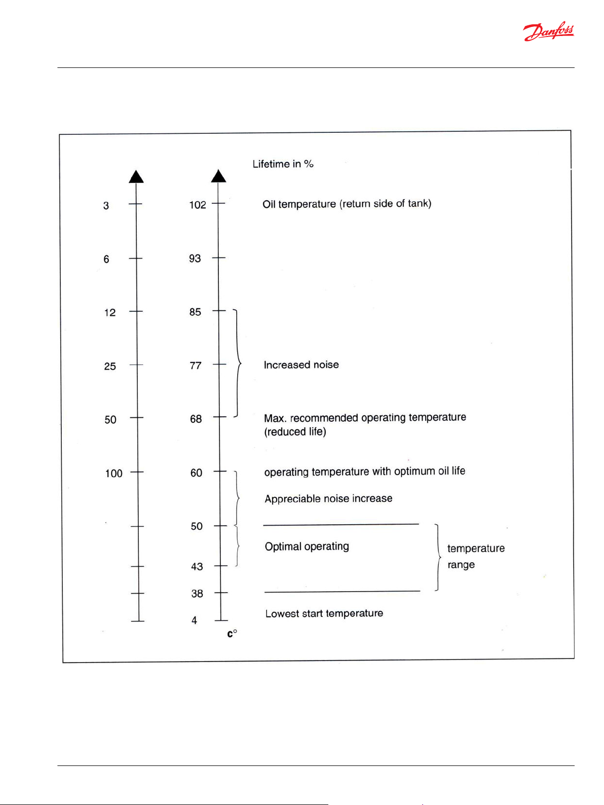
Normally an oil operating temperature of 30- 60C ought to be aimed at since the life of hydraulic oil is
strongly dependent on its operating temperature. The rule-of-thumb is that the useful life of an oil is
halved for every 8°C the temperature rises above 60°C. That is to say, at 90°C the life of the oil is only
about 10% of its life at 60°C.
The reason for this is oxidation. At atmospheric pressure, all oils contain a little less than 0.1 liters of air
per liter of oil. Therefore, in practice, oxygen is always present and it reacts with the hydrocarbons
making up the oil gradually, as oxidation increases, the oil becomes darker in color and its viscosity rises.
Finally, the products of oxidation can no longer be dissolved in the oil, but instead settle everywhere in
the system as a brown sticky layer. This will cause sticking valves and high friction in ball bearings, valve
spools and pump pistons. Oxidation also produces corrosive acids.
The oxidation process begins gradually, but at a certain stage the oxidation rate suddenly rises and the
viscosity rises. The resulting increase in operating temperature accelerates the oxidation process even
more and soon the oil becomes quite unusable as a hydraulic oil because of deposits, high viscosity and
accumulated acids. It therefore pays to take care of the oil. Even without proper laboratory equipment
many factors can be checked.
The presence of water
Viscosity
The smell and appearance
It is possible to make the following checks:
The presence of water can be detected as follows. Drain two or three cm3 of oil into a test tube and allow
it to stand for a few minutes until any air bubbles have disappeared. Then heat up the oil, with a gas
lighter, for example, and at the same time listen (at the top of the test tube) for small "explosions" in the
oil. This sound comes from the creation of water vapor when the small water particles in the oil are shockboiled.
Viscosity can be established with sufficient accuracy using homemade equipment consisting of a small
container (e.g. a can) able to hold ¾ liters. The bottom of the can must be pushed slightly outwards and a
burr-free hole of 4-5 mm drilled. Pour water which has been heated to 40 - 50°C into the can whilst
keeping a finger over the hole. Remove the finger and record in seconds how long it takes for the water
to run out. Repeat the process, but this time use oil. The viscosity of the oil can be calculated in degrees
Engler (E°).
Engler viscosity =
See Tables for conversing viscosity on page 20.
The smell and appearance of an oil sample also reveals much about its condition, especially if it is
compared with a sample of clean unused oil at the same temperature and in the same kind of glass
©
Danfoss | October 2019 BC317769130475en-000101 | 19
Page 20
Technical Information
Tips on Hydraulics
Checking the oil
Tables for conversing viscosity
container. By allowing two such samples to stand overnight, the bottom of the glass containing the used
oil might reveal a deposit. If it does the oil in the system must be fine-filtered and the tank cleaned.
If these relatively crude tests indicate that the oil might be bad, small systems should scrap the oil. For
larger systems an oil sample of approx. ½ - 1 liter should be sent to a laboratory for a thorough check.
Remember it is important that the bottles used for the samples are completely clean.
cSt = Centistoke E° = Engler° R = Redwood S = Saybolt
Conversing viscosity
cSt E° R S cSt E° R S
1,00 1,00 26,7 29,3 26,00 3,58 109,1 123,6
1,50 1,07 28,4 31,3 27,00 3,71 113,0 128,0
2,00 1,12 30,3 33,1 28,00 3,83 117,0 132,4
2,50 1,17 31,7 34,8 29,00 3,96 120,9 136,8
3,00 1,22 33,0 36,5 30,00 4,09 124,8 141,3
3,50 1,27 34,5 38,0 31,00 4,21 128,8 145,7
4,00 1,31 35,8 39,5 32,00 4,34 132,7 150,2
4,50 1,35 37,1 41,0 33,00 136,6 154,7
5,00 1,40 38,5 42,5 34,00 4,58 140,6 159,2
5,50 1,44 39,7 44,0 35,00 4,71 144,4 163,7
6,00 1,48 41,1 45,4 36,00 4,83 148,8 168,2
6,50 1,52 42,4 47,0 37,00 4,96 152,5 172,8
7,00 1,57 43,8 48,6 38,00 5,09 156,5 177,3
7,50 1,60 45,2 50,2 39,00 5,22 160,5 181,9
8,00 1,65 46,5 51,8 40,00 5,34 164,5 186,5
8,50 1,70 48,0 41,00 5,47 168,6 191,0
9,00 1,75 49,4 55,1 42,00 5,60 172,6 195,6
9,50 1,79 51,0 56,8 43,00 176,6 200,2
10,00 1,83 52,4 58,5 44,00 5,86 180,7 204,8
10,50 1,88 53,9 60,2 45,00 184,7 209,4
11,00 1,93 55,4 62,0 46,00 6,11 188,7 214,1
12,00 2,02 58,5 65,6 47,00 6,25 192,8 218,7
13,00 2,12 61,8 69,3 48,00 6,37 196,8 223,3
14,00 2,22 65,1 73,1 49,00 6,50 200,8 227,9
15,00 2,32 68,4 77,0 50,00 6,63 204,8 232,6
16,00 2,43 71,8 81,0 51,00 6,76 208,9 237,2
17,00 2,54 85,0 52,00 6,88 213,1 241,8
18,00 2,65 79,0 89,2 53,00 7,01 217,2 246,5
19,00 2,76 82,8 54,00 7,15 221,3 251,1
20,00 2,88 86,7 97,6 55,00 7,27 225,3 255,7
21,00 2,99 90,4 101,9 56,00 7,40 229,4 260,4
22,00 3,10 94,0 106,2 57,00 233,4 365,0
23,00 3,22 97,8 110,5 58,00 7,67 237,4 269,6
24,00 3,35 101,5 114,9 59,00 7,79 241,4 27,.2
25,00 3,46 105,2 119,2 60,00 7,92 245,5 278,0
20 | © Danfoss | October 2019 BC317769130475en-000101
Page 21
Technical Information
Tips on Hydraulics
Checking the oil
Hydraulic oil temperature conditions oil life in %
©
Danfoss | October 2019 BC317769130475en-000101 | 21
Page 22

Technical Information
Tips on Hydraulics
Installation of system
After the designer has made calculations and selected the correct components, a number of questions
have to be considered:
Where and how are the components to be placed?
This must be in strict accordance with, amongst others, the following factors:
•
Suitability in relation to the work the motor or cylinder must perform.
•
Easily accessible for installation and inspection, and not least for repair or replacement. There is no
such thing as a system that never needs to be repaired.
•
Maximum heat emission is obtained by locating individual components, tanks, pipes, hoses and
filters at the outer boundaries of the system. If pipes are bracketed to the machine frame or vehicle
chassis, large amounts of heat will be given off.
•
Noise suppression is the subject of environment legislation and much can be achieved by installing
pumps and their motors on dampers and by using hoses between all moving/vibrating components
and rigid parts.
Remember to follow catalog instructions on pipes, hoses and fittings.
Remember that pipes which are welded or hot-bent must be thoroughly cleaned. Scale etc. must be
cleaned by wire brushing or by pickling followed by thorough flushing and drying.
Remember it is very advisable to read the supplier's directions and meet the requirements contained in
the installation instructions which nearly always accompany components.
Remember the three most important rules to be followed when working with hydraulics are:
1. CLEANLINESS
2. CLEANLINESS
3. CLEANLINESS
Rule 1
Concerns cleanliness during the installation of the hydraulic system. Hoses, pipes and fittings are never
clean after being worked on and must therefore always be cleaned immediately prior to installation.
Pipes, including pipe bends, should preferably be cleaned with a plug of crepe paper or lint-free cloth
soaked in paraffin and blown through the pipe with com pressed air. This process must be repeated with
several plugs until a completely clean plug emerges. If pipes have been hot-bent or welded they must be
cleaned by pickling in hydrochloric acid, flushed with cold and then hot water and dried. If the pipes are
not to be fitted immediately, they must be lubricated with clean hydraulic oil and plugged, otherwise
they will rust. The blanking plugs fitted in all pumps, motors, valves, etc. must not be re moved until just
before the components are installed.
Workshops, work stations, tools and clothing must also be as clean as possible. Then there is smoking!
Apart from the fire risk, tobacco ash is harmful, it acts as an abrasive. Smoking should therefore be
prohibited.
22 | © Danfoss | October 2019 BC317769130475en-000101
Page 23
Technical Information
Tips on Hydraulics
Installation of system
Fine filtration of the oil via a filling filter unit
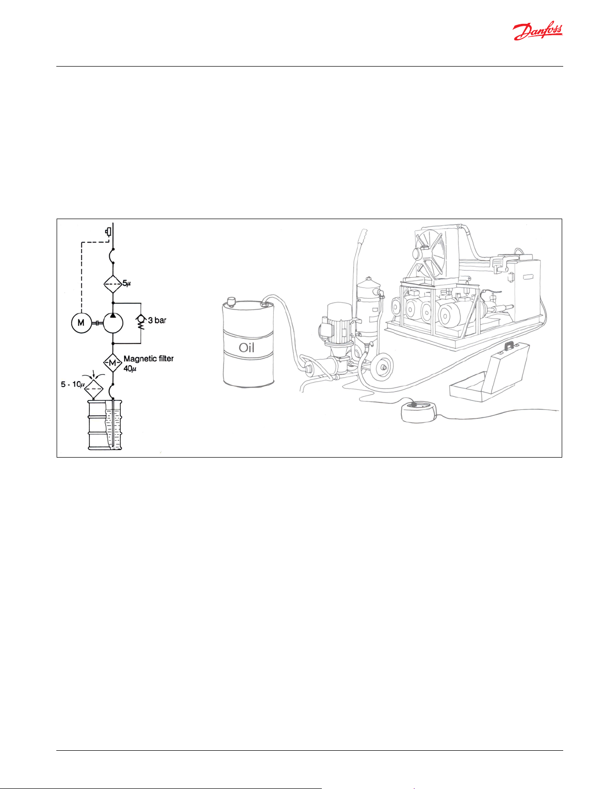
Fine filtration of the oil via a filling filter unit is strongly recommended. When filling from drums there are
nearly always too many particles in the oil, especially in the bottom where there is often a little water too.
An example of a portable filling filter unit is shown below. It consists of a ¾ hk single phase electric motor
driving a low pressure pump of 15-20 I/min capacity. The pump sucks from the oil drum through a pipe
that can be screwed into the ¾ BSP drum connector. The diagonally cut end of the pipe extends to
approx. 4-5 cm above the bottom. Oil is sucked through a 40 µm coarse strainer with magnetic insert and
then through a 5 µm fine filter. The fine filter can be equipped with a low pressure switch that stops the
pump when the filter is about to become saturated with dirt particles.
©
Danfoss | October 2019 BC317769130475en-000101 | 23
Page 24
Technical Information
Tips on Hydraulics
Installation of system
Rule 2
Rule 3
Concerns cleanliness during daily operation of a hydraulic system. Here, the main objective is to prevent
the oil from becoming dirty. That is to say, filters (including air filters) must be clean - especially piston
rods, shafts and shaft seals. It has been proven that on every square centimeter of piston rod area, one
dirt particle of more than 10μm penetrates the cylinder. Imagine a piston rod of ᴓ50 mm, a length of just
100 mm, and a velocity of 12 m/min. This means about 20.000 particles larger than 10 μm per minute!
The tools used for filling must of course be perfectly clean and the oil filled into the system must be
filtered through filters of the same fineness as the finest in the system, normally 5 µm, but in any event no
coarser than 10 µm nominal. Oil in large drums is not normally clean enough and, depending on the
storage, often contains water. Therefore drums should be laid down during storage, or better still, should
stand on a slant if kept out doors so that water cannot collect around the plugs.
Concerns cleanliness during inspection and repair. Here also it goes without saying that everything
should be kept as clean as possible. Before a hydraulic component is removed, both the component itself
and the immediate surroundings must be clean. All loose paint scale must be removed before screwed
connections are dismantled and all open parts, pipes, hoses, etc. must be blanked off with, for example,
plastic bags bound on so that dirt and dust cannot enter the system when it is in standstill.
A hydraulic component must never be dismantled outdoors, but always in a closed workshop equipped
with necessary facilities, special equipment and trained personnel.
24 | © Danfoss | October 2019 BC317769130475en-000101
Page 25

Technical Information
Tips on Hydraulics
Starting up and running-in
Procedure for starting up
Correct starting up and running-in is of the utmost importance in ensuring that the system runs for a long
time without problems. All to often, many systems and especially pumps "die" after only a few hours
running, some after only a few minutes, because the most elementary steps have been overlooked. One
example is the non-observance of the cleanliness rules before and during start-up.
But despite even the best degree of cleanliness and care during installation, the presence of dirt in a new
system cannot be avoided. During running-in, wear particles will be produced from all moving parts. It is
therefore important not to apply full load to the system before this dirt has been filtered out.
Let us look at our system which is fitted with a Danfoss pump type VPA and study the procedure for
starting up:
1. Examine the tank to make sure it is perfectly clean internally. If it is not, clean it out with a vacuum
cleaner. Often during installation, it is necessary to bore and tap a few extra holes which are not
shown on the drawing.
2. Fill with clean oil of the correct type - through a filtering unit as described in The return line and return
filter on page 27. If such a unit is not available, any filling funnels, cans, hoses must be thoroughly
cleaned before they are used. Oil is filled through the return filter.
3. Before the pump is started, check the following:
•
Have all the flanges and screwed connections been tightened? (There is always one that hasn't).
•
Is the directional valve in its neutral position? (If it is not, the results can be catastrophic).
•
Is the pressure relief valve set at minimum? (The result of a leak or a malfunction is more violent at
high pressure than at low pressure).
•
Does the pump rotate in the correct direction? (Nearly all pumps have a particular direction of
rotation: clockwise or counterclockwise looking on the end of the output shaft. The direction
ought to be clearly marked with an arrow. Many pumps will not withstand being rotated in the
wrong direction for more than a few minutes).
•
Is the pump and any suction line filled with oil? (Some pumps cannot withstand being rotated for
more than a few minutes without oil in the pump housing).
4. Connect a vacuum meter in the suction line, as close to the pump as possible. Connect a 250 bar
pressure gauge to the high pressure side of the system. Connect a 5 bar pressure gauge to the upper
drain connection. Pumps with a priming pump must be fitted with a 25 bar pressure gauge on the
priming pump take-off. If there is more than one pump on the same shaft, each pump must be fitted
with these pressure gauges.
5. If possible, connect the discharge side of the pump to the tank, otherwise to a 5-10 liter container.
6. Set the pump displacement to at least 40% of maximum.
7. Start the pump (with a combustion engine at 800-900 r/min, or with an electric motor having short -
duration start/stop functions). When the pump starts to suck (oil runs into the tank or container) stop
the pump and connect its pressure outlet to the high pressure side of the system.
8. If the pump does not suck relatively quickly, check the following:
•
Is the suction line leaky?
•
Is there free flow in the suction line?
•
Does the pump rotate at all?
Is the pump set for minimum 40% displacement?
9. Start the pump once more. Operate each directional valve for each motor or cylinder one after
another, with a necessary bleeding at as low a pressure as possible. Repeat until the return oil in the
tank does not foam and the motors and cylinders operate smoothly. Check the oil level frequently
and refill with filtered oil.
10. A further frequent check: make sure that the suction pressure is at least 0.8 bar absolute,
corresponding to 0.2 bar on the scale. After a short time, the drain pressure must be maximum 1 bar.
©
Danfoss | October 2019 BC317769130475en-000101 | 25
Page 26

Technical Information
Tips on Hydraulics
Starting up and running-in
11. Set the pump for maximum displacement and the motor for maximum speed (but not higher than
3150 r/min continuous) and allow the system to run unloaded for about 20 minutes, until the oil
temperature has stabilized. Reverse the direction of the motor and the travel of the cylinders
frequently.
12. Set the individual pressure relief valves and the pump pressure control valve at the specified
pressure. Any shock valves in the system must be set at approx. 30-40 bar over the constant
operating pressure. Check the oil temperature.
13. If required, the pump maximum oil flow can be set using the flow limiter.
14. Remove the pressure gauges and vacuum meter and insert plugs in the connections. Replace filter
inserts with new ones. Check the oil level.
15. If there is a large amount of oil (for example, more than 100 liters in the system), an oil sample can be
taken and sent to the oil supply firm for analysis.
16. The system can now be put to work.
26 | © Danfoss | October 2019 BC317769130475en-000101
Page 27

Technical Information
Tips on Hydraulics
Maintenance
Periodic inspection
The tank
Nearly all hydraulic systems, stationary as well as mobile, are accompanied by operating instructions, but
the issue of maintenance instructions is just as important. To be able to correctly maintain a hydraulic
system, the customer (end user) must know what has to be done. The transfer of this knowledge is the
responsibility of the manufacturer.
The regular inspection of a hydraulic system is more economical than making repairs when a fault occurs.
If a fault does occur, the whole system ought to be checked rather than just the defective component.
Regular planned preventative maintenance of the system after a certain number of operating hours and
the scheduled replacement of important seals ensures the avoidance of costly operational stops.
To avoid forgetting something, a routine following the direction of oil flow should be adopted, beginning
with the tank.
The oil level must be correct and the oil must be of the prescribed type and viscosity. On large systems it
pays to send oil samples for analysis at regular intervals. Factors of special importance in deciding
whether the oil can continue to be used are the rise in oil viscosity, the acidity number and the content of
impurities. If there is no special equipment available, the oil by looking at its color. Poor oil can be dark, it
can smell rancid or burnt; or it can be yellow, unclear or milky, which indicates the presence of air or
emulsified water. And of course the oil might contain free microscopic metal particles and other foreign
substances.
The suction line
The suction line must be inspected for damage and sharp bends that reduce the bore of the pipe and
create noisy cavitation. Screwed connections must be inspected for leaks and tightened if necessary.
Rubber or plastic hoses are suspect because they often become contracted by vacuum when the oil is
hot. Such items should be replaced with pipes or armored hoses.
The pump
The pump must be inspected for shaft seal and other leakage. If the pump is driven by V belt, this should
be examined to ensure that it is not worn and is correctly tensioned. The different circuits on the pressure
side must be examined individually, following the direction of oil flow.
There must be no leaks. Look on the floor under the vehicle for oil patches. The finger tips are good
instruments for sensing faults, the ears too - by using a screwdriver or similar tool as a stethoscope,
irregularities which might later cause breakdown can often be heard.
The return line and return filter
The return line and return filter must be inspected for leaks, etc. and the filter must be checked. If the
filter has a dirt indicator the condition of the filter can easily be seen. If there is no dirt indicator, the filter
has to be taken out to see whether it needs cleaning or replacement.
©
Danfoss | October 2019 BC317769130475en-000101 | 27
Page 28

Technical Information
Tips on Hydraulics
Fault location
Under this heading, it is obvious that the two basic factors, pressure and flow, must be in accordance with
specifications. If the opposite is true nothing will function perfectly. If the condition of the pump is
suspect, the pressure line from the system must be disconnected and a pressure gauge fitted, together
with a throttle valve and flow meter, as shown in the sketch below.
Pump test
If no flow meter is available, a Danfoss hydraulic motor can be fitted instead. The displacement of the
motor per revolution with unloaded shaft is very precise and to find flow all that is necessary is to count
the number of revolutions per minute and multiply the figure by the displacement, as shown in the
following examples:
Example 1: OMR 100:
Example 2: OMR 315:
Check the flow with completely open throttle valve.
Increase the throttle until it corresponds to normal operating pressure.
Again check the flow and compare it with the values given in the pump catalogue.
The volumetric efficiency of the pump can be calculated thus:
If the capacity with operating pressure, and thereby the µ vol. is too low, the pump has internal
leakage - as a rule because of wear or seizing.
28 | © Danfoss | October 2019 BC317769130475en-000101
Page 29

Technical Information
Tips on Hydraulics
Fault location
Fault location general
THINK before starting fault location!
Every fault location process should follow a logical and systematical order. Usually it is wisest to start at
the beginning:
•
Is the oil level correct when the pump is operating?
•
Is the condition of oil and filters acceptable?
•
Are pressure, flow and flow direction as specified?
•
Is the oil temperature too high or too low (oil viscosity)?
•
Are there any unrequired vibrations or noise (cavitation)?
If the driver of the vehicle is available ask him:
•
what type of fault it is and how it affects the system
•
how long he has felt that something was wrong
•
whether he has "fiddled" with the components
•
whether he has any hydraulic and electrical diagrams available.
Diagrams are often found in the instructions included with vehicles/machines. Unfortunately they are
often so schematic that they are not of much use in a fault location situation. However, the order of and
the connections between the individual components are often shown.
When a defect component has, with certainty, been found both the component and its surroundings
must be cleaned before removal. Loose paint must also be removed from pipes and fittings.
Holes, hoses and pipe ends must be blanked off with plugs or sealed with, for example, plastic bags after
removal to avoid the entry of dirt during standstill. Never dismantle hydraulic components outside. We
recommend that repairs be carried out in a workshop on a clean workbench perhaps covered with
newspaper.
Make sure that a Danfoss service manual dealing with the product in question is handy. Follow the
instructions word for word both when dismantling and assembling because if these instructions are not
followed closely serious faults may develop. NB. In some cases special tools are necessary for assembling.
Our service manuals give full guidance as to when this is the case.
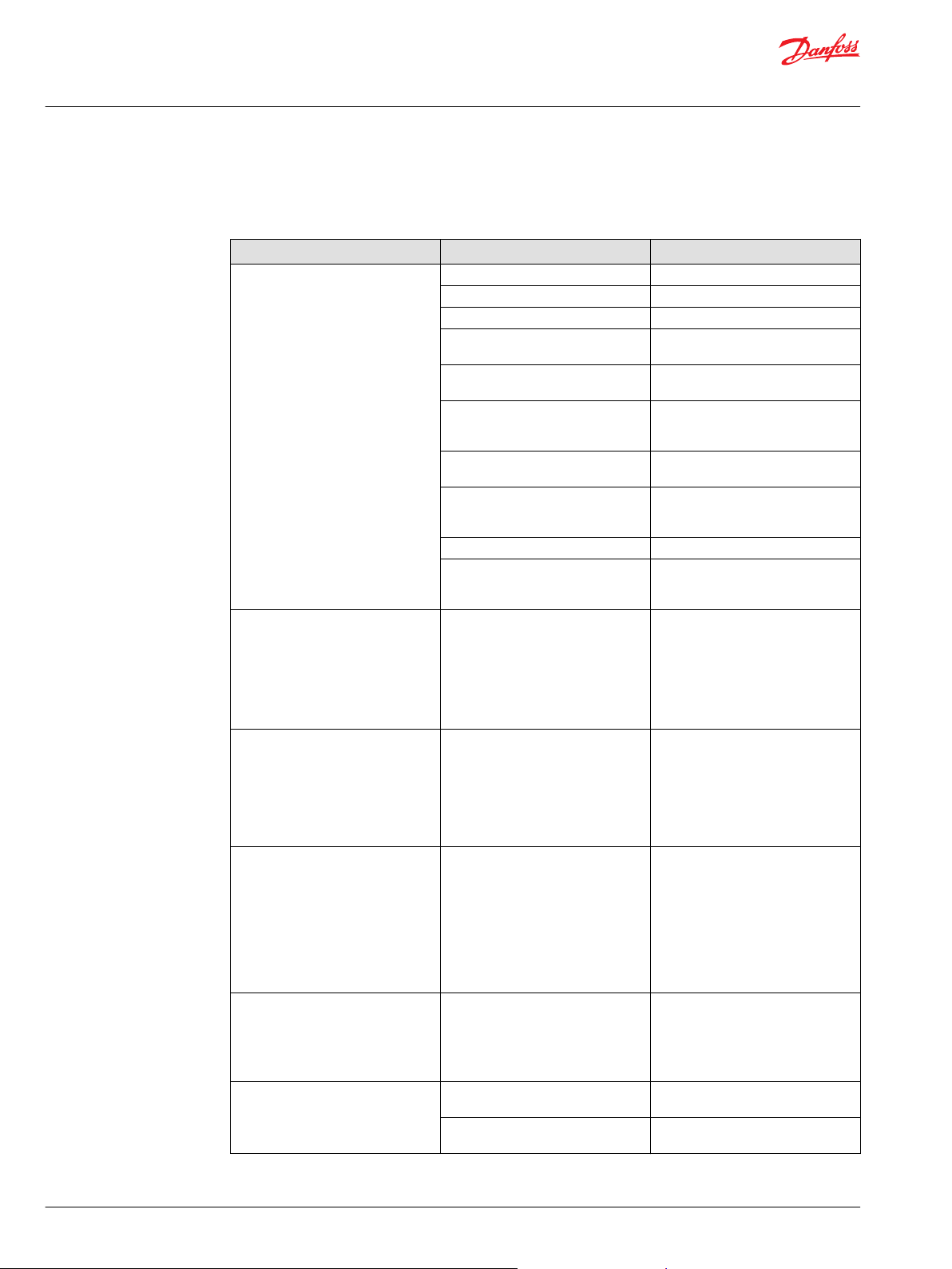
Hydraulic pumps
Hydraulic pumps fault location tips
Fault Possible cause Remedy
Pump noisy No or insufficient oil supply to pump. Clean suction filter. Check that no
Viscosity of oil too high. Change the oil, adjust viscosity to
Pump takes in air:
At the pump shaft.
•
At loose or damaged suction line.
•
Oil level too low.
•
Oil takes in air in the tank (return
•
pipe discharging over oil surface).
Pump worn out. Repair or replace pump.
R.P.M. too high. Adjust the R.P.M.
Oil pressure too high. Adjust oil pressure.
©
Danfoss | October 2019 BC317769130475en-000101 | 29
damage or narrowing is to be found
on suction line.
working temperature.
Replace shaft seal. Tighten fittings or
replace suction line. Refill with clean
oil. Extend return pipe to 54 cm
under the surface and as far as
possible from the suction pipe.
Page 30

Technical Information
Tips on Hydraulics
Fault location
Hydraulic pumps fault location tips (continued)
Fault Possible cause Remedy
No pressure Oil level too low. Refill with clean oil.
Pump does not run or runs in the
wrong direction.
Relief valve is stuck in open position. Repair relief valve.
Pump defective, broken shaft or key
for rotor.
No or unstable pressure Working pressure too low Check pressure adjusting valve.
Leaky pressure adjusting valve or
pilot valve.
The oil flows more or less to the tank
through defective valve or cylinder.
Noise and relief valve Excessive flow. Fit a larger valve corresponding to
Dirt or chips between valve cone and
valve seat.
Air in the system, foam in the oil Leaky suction line. Re-tighten or replace pipe.
Excessive resistance in suction line. Clean filter and suction line, or
Return line discharges above the oil
level - could cause foam formation.
and extend if necessary.
Incorrect oil type. Change over to correct oil type.
Overheated system No supply of cooling water. Re-establish supply of cooling water.
Oil cooler blocked or dirty. Clean oil cooler.
Excessive oil viscosity. Change over to correct oil type.
Abnormal internal leakage in one or
more components.
Altered running conditions. Establish extra cooling if necessary.
Pump, valves or motor overloaded. Reduce load or replace component
Adjust direction of rotation. Check
driving belt or coupling.
Repair pump.
Repair valve.
Repair cylinder or valve.
the actual oil volume.
Repair valve.
replace with pipes having larger
bores. Check fittings.
Remove return line from suction line.
Repair or replace defective
components.
with a bigger one.
Hydraulic motors
Hydraulic motors fault location tips
Fault Possible cause Remedy
R.P.M. of motor lower than rated
value
Pump worn out. Repair or replace pump.
R.P.M. of pump too low. Adjust the R.P.M.
Motor worn out. Repair or replace motor.
Oil temperature too high (resulting in
excessive internal leakage in motor,
valves, etc.). Possibly too high
ambient temperature.
Insufficient diameter in pipes, etc. Fit lines with larger diameter.
Pump cavitation. See under: Pump noise.
Opening pressure of pressure relief
valve too low.
Leaky control valve. Repair valve.
Overloaded motor. Eliminate the cause of the overload or
Build in oil cooler or increase existing
cooler or tank capacity. If necessary
change over to oil with a higher
viscosity.
Adjust to correct pressure.
change over to larger motor.
30 | © Danfoss | October 2019 BC317769130475en-000101
Page 31

Technical Information
Tips on Hydraulics
Fault location
Hydraulic motors fault location tips (continued)
Fault Possible cause Remedy
Motor shaft does not rotate Pump does not run or runs in the
Motor shaft rotates in the wrong
direction
Leakage at motor shaft Shaft seal worn out or cut. Replace shaft seal.
Leak between motor spigot and
housing
Leaks between housing, spacer plate,
gear wheel set and end cover,
respectively
wrong direction.
Motor spool has seized in housing. Replace complete shaft and housing.
Cardan shaft or spool broken (shaft
and commutator valve in two).
Working pressure too low. Adjust opening pressure of relief
Sand, steel chips or similar impurities
in motor.
Oil lines are wrongly connected to
direction motor ports.
Gear-wheel and rotary valve
incorrectly fitted.
Spigot is loose. Tighten screws with prescribed
O-ring defective. Replace O-ring.
Screws loose. Tighten screws with prescribed
O-rings defective. Replace O-rings.
Steel washers defective. Replace steel washers.
Start pump or reverse direction of
rotation.
Replace cardan shaft or complete
shaft and housing. Eliminate external
forces which caused the fracture.
valve to higher value, however,
within permissible limits. If necessary,
change over to motor with higher
torque.
Clean the motor, and flush system
thoroughly. Renew defective parts.
Use a better filter.
Change the connections.
Adjust settings.
torque.
torque.
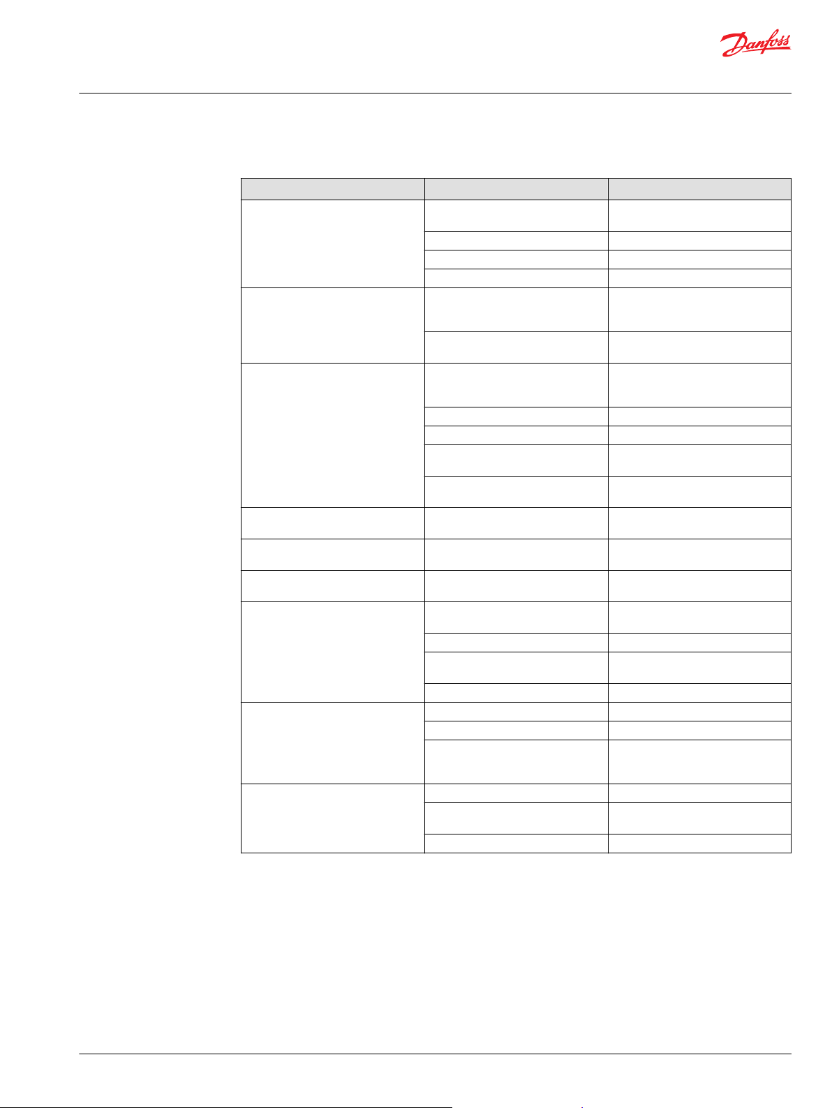
Steering systems with OSPB - OSPC - OVP/OVR - OLS
Follow these quick methods of testing steering systems:
1. Start the motor (pump) and let it run for a couple of minutes.
2. Drive slowly in a figure of eight. Pay special attention to any shaking or vibration in the steering wheel
or steered wheels. See whether the steering wheel movements are immediately followed by a
corresponding correction of the wheel movements, without any "motoring" tendencies.
3. Stop the vehicle and turn the steering wheel with small quick movements in both directions. Let go
of the steering wheel after each movement. The steering wheel must immediately go back to the
neutral position, specifically there should be no "motoring" tendencies.
4. While the vehicle is still stationary turn the steering wheel from stop to stop. Count the number of
times the steering wheel turns in both directions.
It must be possible to turn the steering wheel with one finger.
Stop the motor (pump) and again turn the steering wheel from stop to stop. Again count the number
of turns and compare with previous figures. If there is a large difference (1 turn or more) the leakage
in the cylinder, gear wheel set, shock valve or suction valve is too large.
With larger vehicles where there is no emergency steering function, turn the steering wheel whilst
the motor is idling.
5. If there is a leak, remove a hose from one of the cylinder ends and plug this and the hose. Try to turn
the steering wheel again. If the wheel cannot turn the cylinder is defective. If this is not the case the
steering unit or valve block is defective.
©
Danfoss | October 2019 BC317769130475en-000101 | 31
Page 32
Technical Information
Tips on Hydraulics
Fault location
Steering units OSPB - OSPC - OVP/OVR - OLS
Steering units OSPB - OSPC - OVP/OVR - OLS
Fault Possible cause Remedy
Steering wheel is heavy to turn No or insufficient oil pressure
Pump does not run Start up pump (loose V-belt)
Pump defective Repair or replace pump
Regular adjustments of the steering
wheel are necessary ("Snake-like
driving")
Neutral position of steering wheel
can-not be obtained, for instance
there is a tendency towards
"motoring"
"Motoring" effect. The steering wheel
can turn on its own.
Backlash
"Shimmy"-effect. The steered wheels
vibrate. (Rough tread on tires gives
vibrations).
Pump runs in the wrong direction
replace pump
Pump is worn out Pump is under
dimensioned
Pressure relief valve is stuck in open
position or setting pressure is too
low.
Priority valve is stuck in open
position.
Too much friction in the mechanical
pans of the vehicle.
Emergency steering balls missing. Install new balls.
Combination: Downstream system+
steering unit with suction valve and
differential cylinder are inexpedient.
1. Leaf spring without spring force or
broken.
2. Spring in double shock valve
broken.
3. Gear wheel set worn.
4. Cylinder seized or piston seals
worn.
1. Steering column and steering unit
out of line.
2. Too little or no play between
steering column and steering unit
input shaft.
3. Pinching between inner and outer
spools.
1. Leaf springs are stuck or broken
and have therefore reduced spring
force.
2. Inner and outer spools pinch,
possibly due to dirt.
3. Return pressure in connection
with the reaction between
differential cylinder and steering
unit too high.
1. Cardan shaft fork worn or broken.
2. Leaf springs without spring force
or broken.
3. Worn splines on the steering
column.
Air in the steering cylinder. Bleed cylinder. Find and remove the
Mechanical connections or wheel
bearings worn.
Correct direction of rotation of pump
Replace pump. Install a larger pump
(examine pressure need and flow).
Repair or clean pressure relief valve.
Adjust the valve to the correct
pressure.
Repair or clean the priority valve.
Lubricate bearings and joints of
steering gear or repair if necessary.
Check steering column installation.
Change cylinder type (through going
piston rod). If necessary use two
differential cylinders.
1. Replace leaf springs.
2. Replace shock valve.
3. Replace gear wheel set.
4. Replace defective parts.
.
1. Align the steering column with
steering unit.
2. Adjust the play and, if necessary
shorten the splines journal.
3. Contact the nearest service shop.
1. Replace leaf springs.
2. Clean steering unit or contact the
nearest service shop.
3. Reduce return pressure, change
cylinder type or use a non-reaction
control unit.
1. Replace cardan shaft.
2. Replace leaf springs.
3. Replace steering column.
reason for air collection.
Replace worn parts.
32 | © Danfoss | October 2019 BC317769130475en-000101
Page 33
Technical Information
Tips on Hydraulics
Fault location
Steering units OSPB - OSPC - OVP/OVR - OLS (continued)
Fault Possible cause Remedy
Steering wheel can be turned the
whole time without the steered
wheels moving.
Steering wheel can be turned slowly
in one or both directions without the
steered wheels turning.
Steering is too slow and heavy when
trying to turn quickly.
"Kick-back" in steering wheel from
system. Kicks from wheels.
Heavy kick-back in steering wheel in
both directions.
Turning the steering wheel activates
the steered wheels opposite.
Hard point when starting to turn the
steering wheel.
Too little steering force (possibly to
one side only).
Leakage at either input shaft, end
cover, gear-wheel set, housing or top
part.
Oil is needed in the tank. Fill with clean oil and bleed the
Steering cylinder worn. Replace or repair cylinder.
Gear wheel set worn. Replace gear wheel set.
Spacer across cardan shaft forgotten. Install spacer.
One or both anti-cavitation valves are
leaky or are missing in OSPC or OVP/
OVR.
One or both shock valves are leaky or
are missing in OSPC or OVP/OVR.
Insufficient oil supply to steering unit,
pump defective or number of
revolutions too low.
Relief valve setting too low. Adjust valve to correct setting.
Relief valve sticking owing to dirt. Clean the valve.
Spool in priority valve sticking owing
to dirt
Too weak spring in priority valve Replace with a stronger spring (There
Fault in the system. Contact vehicle supplier or Danfoss.
Wrong setting of cardan shaft and
gear wheel set.
Hydraulic hoses for the steering
cylinders have been switched around.
Spring force in priority valve too
weak.
Air in LS and /or PP pipes. Bleed LS and PP pipes.
Clogged orifices in LS or PP side
priority valve.
Oil is too thick (cold). Let motor run until oil is warm.
Pump pressure too low. Correct pump pressure.
Too little steering cylinder. Fit a larger cylinder.
Piston rod area of the differential
cylinder too large compared with
piston diameter.
Shaft defective. Replace shaft seal, see Service Manual
Screws loose. Tighten screws, torque 3-3,5 daNm or
Washers or 0-rings defective. Replace washers and 0-rings.
system.
Clean or replace defective or missing
valves.
Clean or replace defective or missing
valves.
Replace pump or increase number of
revolutions.
Clean the valve, check that spool
moves easily without spring.
are 3 sizes: 4, 7 and 10 bar).
Correct setting as shown in Service
Manual.
Reverse the hoses.
Replace spring by a stronger (4, 7 and
10 bar).
Clean orifices in spool and in
connecting plugs for LS and PP.
Fit cylinder with thinner piston rod or
2 differential cylinders.
steering unit (2,5-3 daNm).
©
Danfoss | October 2019 BC317769130475en-000101 | 33
Page 34

Technical Information
Tips on Hydraulics
Fault location
Steering systems with OSQA/B and OSPBX-LS
Steering systems with OSQA/B and OSPBX-LS fault location tips
Fault Possible cause Remedy
Amplification too large.
Amplification too small.
Heavy turning of steering wheel and
slow increase of amplification.
No end stop in one or both
directions.
"Hard" point when starting to turn
the steering wheel.
No pressure build-up.
1. Dirty, leaky or missing check
valve(1).
2. Piston (2) sticks in the open
position.
1. Piston(2) sticks in the closed
position
2. Piston (2) incorrectly installed
(only OSQA/B-5).
1. Dirty orifices (3) in directional
valve.
2. Dirty orifice(4) in the combi-valve
spool.
3. Dirty orifice (5) in housing.
4. Dirty orifice (6) in LS-port.
5. Dirty orifice in throttle/check valve
(7) in PP-port.
1. One or both shock valves (8) set
too low.
2. One or both anti-cavitation
valves(9) leaky, or sticking.
3. Missing end-stop plate (s) (pas. 10)
for directional valve.
1. Air in LS and/or PP pipes.
2. Spring force in the built in priority
valve too weak(11).
3. Orifices in respectively LS-(6) or
PP- (7) ports blocked.
1. LS-pressure limitation valve(12)
adjusted too low.
2. Spool and sleeve in OSPBX
steering unit put together
incorrectly.
3. Emergency control ball in steering
unit missing Pump does not run or
is defective.
1. Clean or replace check valve.
2. Clean and check that the piston
moves easily.
1. Clean and check that the piston
moves easily.
2. Rotate the piston 180° on its axis.
1. Clean or replace orifice.
2. Clean or replace orifice.
3. Clean or replace orifice.
4. Clean or replace orifice.
5. Clean or replace throttle/check
valve.
1. Setting takes a long time without
special equipment. Contact the
nearest service shop.
2. Clean or replace completely
shock/anti-cavitation valve(s).
3. Fit end-stop plates.
1. Bleed pipes.
2. Replace spring by one which is
more powerful. (There are three
sizes: 4, 7 and 10bar).
3. Take out and clean orifices.
1. Remove plug and set to specified
pressure.
2. Take out spool set and turn the
inner spool 180° in the outer
sleeve. (See Service Manual)
3. Install new ball.
4. Repair or replace pump.
34 | © Danfoss | October 2019 BC317769130475en-000101
Page 35
Technical Information
Tips on Hydraulics
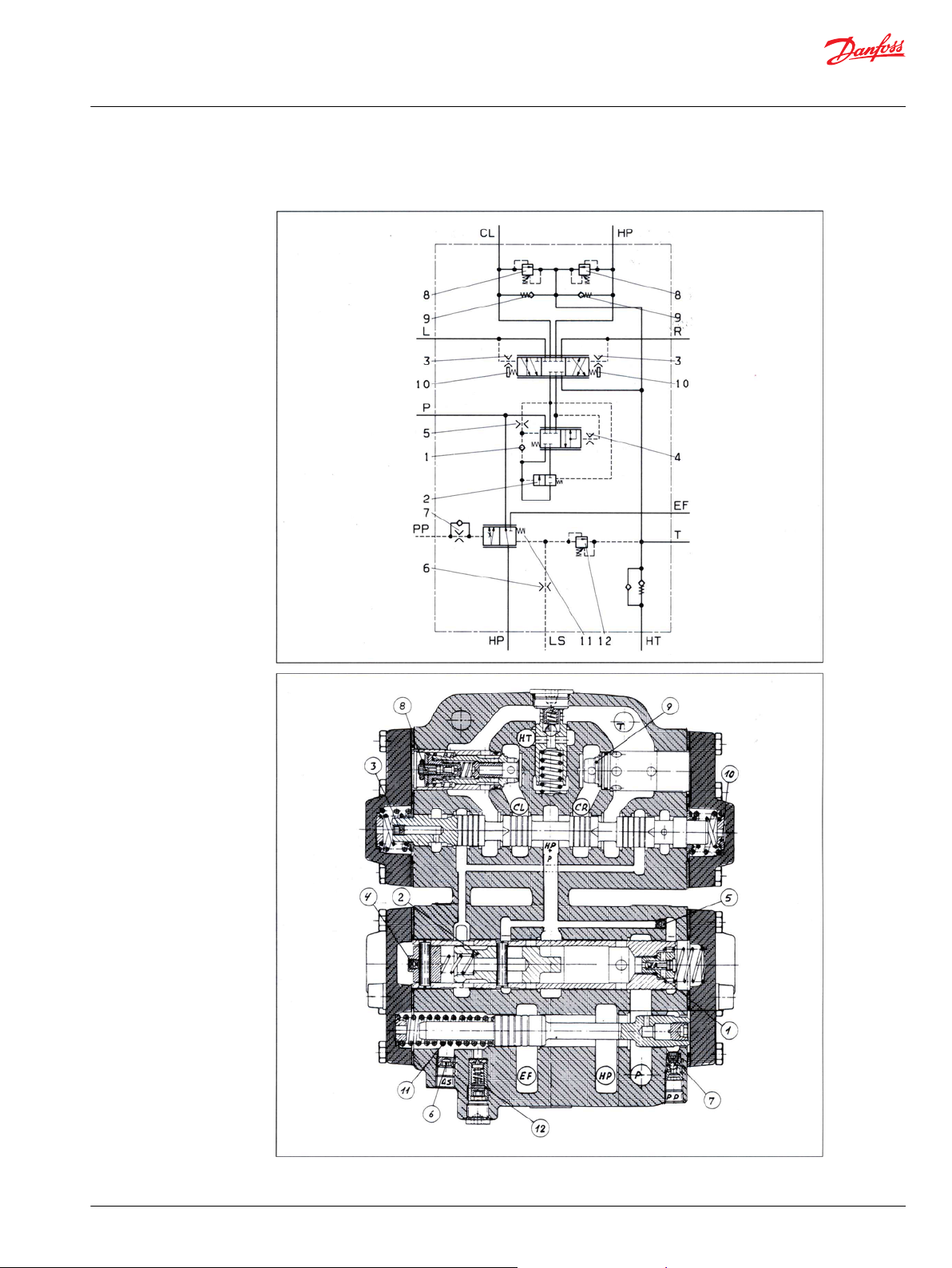
Fault location
Faults locations illustrations
©
Danfoss | October 2019 BC317769130475en-000101 | 35
Page 36
C
Technical Information
Tips on Hydraulics
Repair and testing
Repair
After fault location has revealed which system component is defective, that component must be
removed and possibly replaced as a new or repaired one. Before removal , both the component and its
surroundings must be cleaned and hoses or pipe ends blanked off with plugs or sealed with plastic bags,
etc. to avoid the entry of dirt during standstill. The decision now to be made is whether the component is
to be repaired domestically or by the producer. If the concerned component is from Danfoss, we
recommend that it be repaired in one of our many service workshops (see list on back page). This
particularly applies to more complicated components like steering units, flow amplifiers, pumps and
proportional valves. For safety reasons, these all need testing with special equipment after
Of course situations can occur where components require immediate repair. We recommend most
strongly that in such circumstances repairs be carried out only in very clean surroundings, in suitable
premises on a tidy workbench perhaps covered with newspaper.
Caution
Dismantling and assembly must only be performed if the repairer has the associated Danfoss service
manuals. If these are not followed, serious faults might develop; faults that could give rise to accidents.
This is more than likely with steering components and proportional valves.
Testing
In general, all hydraulic components that have been dismantled ought to be tested on a suitable test
panel to reveal possible assembly errors. If this is impossible, testing must be performed on the system.
36 | © Danfoss | October 2019 BC317769130475en-000101
Page 37
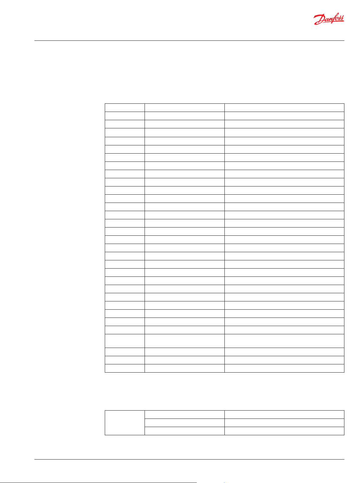
Technical Information
Tips on Hydraulics
Symbols and Tables
Symbols
Symbols
q = Displacement : cm
n = Revolutions : min
p = Pressure : bar
Δp =
Pressure drop : bar
Q = Oil capacity : I/min = dm3/min
v = Speed : m/s
I = Length : m
D = Piston diameter : mm
d = Piston rod diameter : mm
Di = Bore of pipe : mm
Dh = Hydraulic diameter : mm
A = Area : cm
a = Ring area : cm
t = Time : s.
m = Volume : kg
F = Force : N
M = Torque : Nm
P = Power : kW
As = Break load : daN
E = Elasticity module : kp/cm
I = Free column length : m
S = Safety factor
v = Kinematic viscosity : mm2/s
ηv = Volumetric efficiency
ηm = Mechanical efficiency
ηt = Total efficiency
k = Resistance figure
Vac = Accumulator size
V
x
Required oil capacity available in
accumulator
P1 = Lowest oil pressure
P2 = Highest oil pressure
P0 = Pre-charge
3
1
2
2
2
Ratio factors
Ratio factors
Power 1 kw 1.36 PS
1 PS 75 kpm/s
0.736 kw
©
Danfoss | October 2019 BC317769130475en-000101 | 37
Page 38
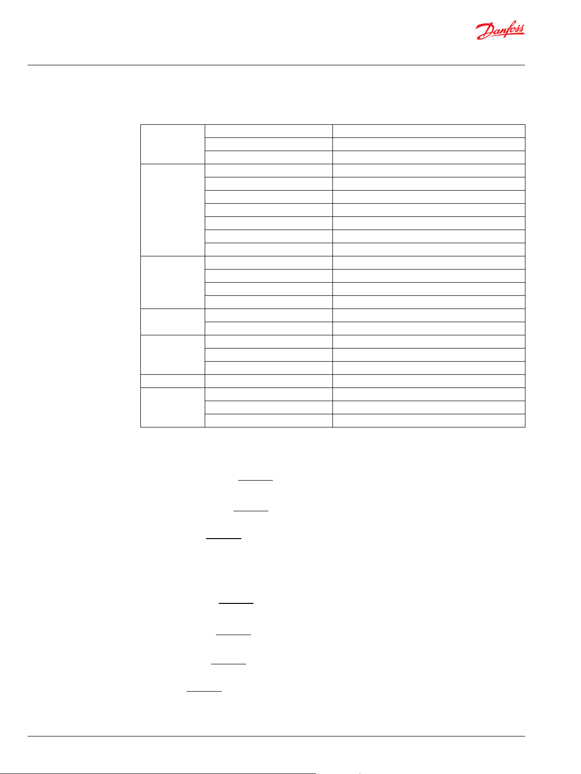
Q x P
600 x ηt
q x n x ηv
1000
q x P
1000 x ηm
q x n
1000 x ηv
q x ∆P x ηm
62.8
Q x ∆P x ηt
600
Q x ηP x 1000
q
Technical Information
Tips on Hydraulics
Symbols and Tables
Ratio factors (continued)
Torque 1 kpm 9.81 Nm
7.233 lbf ft
1 Nm 0.102 kpm
Pressure 1 kp/cm
Volume 1 US gallon 3.785 liter
Area 1 in
Speed 1 km/h 0.2778 m/s
Acceleration 1 fuss/s
Length 1 in 25.4 mm
2
1 psi 0.06895 bar
1 bar 1.0194 kp/cm
1 Eng. gallon 4.546 liter
3
1 in
1 liter 1.0 dm3
2
2
1 fuss
1 fuss/s 0.3048 m/s
1 mile/h 0.447 m/s
2
1 fuss 0.3048 m
1 yd 0.9144 m
98.000 Pa
0.981 bar
9.81 N/cm
14.22 psi
0.0703 kp/cm
16.38 cm
645.2 mm
92900 mm
0.3048 m/s
2
2
2
3
2
2
2
Pump
Motor
Power consumption Nan =
Supplied oil capacity Q =
Input torque M =
Oil consumption Q =
Output torque M =
Output power N =
Speed n =
[min1]
[kW]
[I/min]
[Nm]
[I/min]
[Nm]
[kW]
38 | © Danfoss | October 2019 BC317769130475en-000101
Page 39
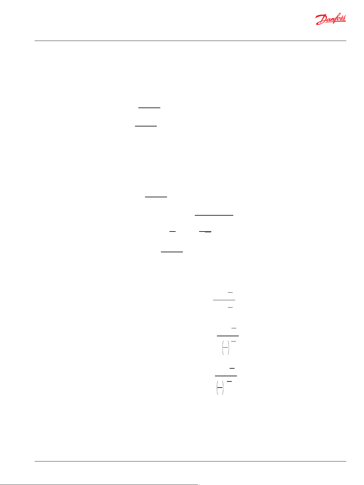
Q x ηv
6 x A
Q x ηv
6 x a
Q x 100
6 x D2 x 0.785
λ x L x 0.89 x v2 x 5
Di
λ turb. =
64
R
e
0.316
4√ R
e
v x Dh x 1000
υ
V
X
P
1
P
0
P
1
P
2
x
1-
V
X
P
1
P
0
P
1
P
2
1
1.5
x
1-
V
X
P
2
P
0
P
2
P
1
1
1.5
x
-1
Technical Information
Tips on Hydraulics
Symbols and Tables
Cylinder
Compressive force F = P x A x ηm [daN]
Tensile force F = P x a x ηm [daN]
Tube
Accumulator size
Speed out v =
Speed in v =
[m/s]
[kW]
Oil consumption out Q = A x v x 6 [I/min]
Oil consumption in Q = a x v x 6 [I/min]
Compressive force with differential cut-in F = P (A - a) ηm [daN]
Flow speed v =
Pressure loads in straight pipe leads =
[m/s]
[bar]
Resistance number: λ lam =
Reynolds number Re =
©
With slow charging and slow discharging Vac =
With quick charging and quick discharging Vac =
With slow charging and quick discharging Vac =
Danfoss | October 2019 BC317769130475en-000101 | 39
Page 40
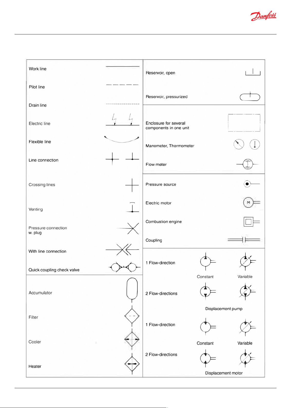
Technical Information
Tips on Hydraulics
ISO/CETOP Symbols
40 | © Danfoss | October 2019 BC317769130475en-000101
Page 41
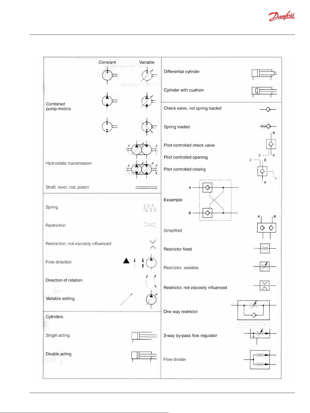
Technical Information
Tips on Hydraulics
ISO/CETOP Symbols
©
Danfoss | October 2019 BC317769130475en-000101 | 41
Page 42

Technical Information
Tips on Hydraulics
ISO/CETOP Symbols
42 | © Danfoss | October 2019 BC317769130475en-000101
Page 43
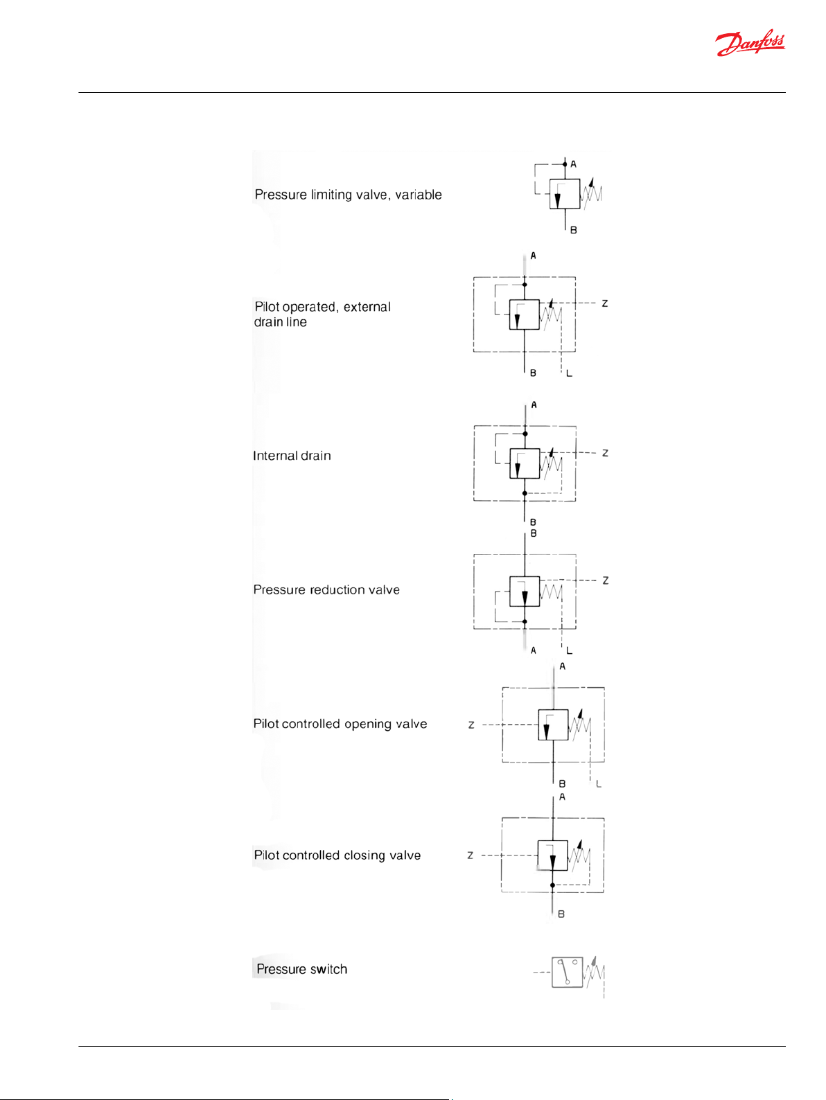
Technical Information
Tips on Hydraulics
ISO/CETOP Symbols
©
Danfoss | October 2019 BC317769130475en-000101 | 43
Page 44

Technical Information
Tips on Hydraulics
Catalogues or leaflets available
Hydraulic components leaflets or catalogues
•
Low speed hydraulic motors
•
Planetary gears
•
Hydrostatic steering units
•
Steering columns
•
Valve blocks
•
Flow amplifiers
•
Priority valves
•
Torque amplifiers
•
Variable radial piston pumps
•
Pump controls
•
Gear wheel pumps for radial piston pumps
•
Proportional valves
•
Remote control units
•
Electronics
Service shops
Please contact the Danfoss Hydraulics sales organization for further information.
Authorized service shops
Service shops
44 | © Danfoss | October 2019 BC317769130475en-000101
Page 45

Danfoss
Power Solutions GmbH & Co. OHG
Krokamp 35
D-24539 Neumünster, Germany
Phone: +49 4321 871 0
Danfoss
Power Solutions ApS
Nordborgvej 81
DK-6430 Nordborg, Denmark
Phone: +45 7488 2222
Danfoss
Power Solutions (US) Company
2800 East 13th Street
Ames, IA 50010, USA
Phone: +1 515 239 6000
Danfoss
Power Solutions Trading
(Shanghai) Co., Ltd.
Building #22, No. 1000 Jin Hai Rd
Jin Qiao, Pudong New District
Shanghai, China 201206
Phone: +86 21 2080 6201
Products we offer:
Hydro-Gear
www.hydro-gear.com
Daikin-Sauer-Danfoss
www.daikin-sauer-danfoss.com
DCV directional control
•
valves
Electric converters
•
Electric machines
•
Electric motors
•
Gear motors
•
Gear pumps
•
Hydrostatic motors
•
Hydrostatic pumps
•
Orbital motors
•
PLUS+1® controllers
•
PLUS+1® displays
•
PLUS+1® joysticks and
•
pedals
PLUS+1® operator
•
interfaces
PLUS+1® sensors
•
PLUS+1® software
•
PLUS+1® software services,
•
support and training
Position controls and
•
sensors
PVG proportional valves
•
Steering components and
•
systems
Telematics
•
Danfoss Power Solutions is a global manufacturer and supplier of high-quality hydraulic and
electric components. We specialize in providing state-of-the-art technology and solutions
that excel in the harsh operating conditions of the mobile off-highway market as well as the
marine sector. Building on our extensive applications expertise, we work closely with you to
ensure exceptional performance for a broad range of applications. We help you and other
customers around the world speed up system development, reduce costs and bring vehicles
and vessels to market faster.
Danfoss Power Solutions – your strongest partner in mobile hydraulics and mobile
electrification.
Go to www.danfoss.com for further product information.
We offer you expert worldwide support for ensuring the best possible solutions for
outstanding performance. And with an extensive network of Global Service Partners, we also
provide you with comprehensive global service for all of our components.
Local address:
Danfoss can accept no responsibility for possible errors in catalogues, brochures and other printed material. Danfoss reserves the right to alter its products without notice. This also applies to products
already on order provided that such alterations can be made without subsequent changes being necessary in specifications already agreed.
All trademarks in this material are property of the respective companies. Danfoss and the Danfoss logotype are trademarks of Danfoss A/S. All rights reserved.
©
Danfoss | October 2019 BC317769130475en-000101
 Loading...